Embed Size (px)
Citation preview

Assessment of Partitioning Processes for Transmutation of Actinides
AFGHANISTAN
ALBANIA
ALGERIA
ANGOLA
ARGENTINA
ARMENIA
AUSTRALIA
AUSTRIA
AZERBAIJAN
BAHRAIN
BANGLADESH
BELARUS
BELGIUM
BELIZE
BENIN
BOLIVIA
BOSNIA AND HERZEGOVINA
BOTSWANA
BRAZIL
BULGARIA
BURKINA FASO
BURUNDI
CAMBODIA
CAMEROON
CANADA
CENTRAL AFRICAN
REPUBLIC
CHAD
CHILE
CHINA
COLOMBIA
CONGO
COSTA RICA
CÔTE D’IVOIRE
CROATIA
CUBA
CYPRUS
CZECH REPUBLIC
DEMOCRATIC REPUBLIC
OF THE CONGO
DENMARK
DOMINICAN REPUBLIC
ECUADOR
EGYPT
EL SALVADOR
ERITREA
ESTONIA
ETHIOPIA
FINLAND
FRANCE
GABON
GEORGIA
GERMANY
GHANA
GREECE
GUATEMALA
HAITI
HOLY SEE
HONDURAS
HUNGARY
ICELAND
INDIA
INDONESIA
IRAN, ISLAMIC REPUBLIC OF
IRAQ
IRELAND
ISRAEL
ITALY
JAMAICA
JAPAN
JORDAN
KAZAKHSTAN
KENYA
KOREA, REPUBLIC OF
KUWAIT
KYRGYZSTAN
LATVIA
LEBANON
LESOTHO
LIBERIA
LIBYAN ARAB JAMAHIRIYA
LIECHTENSTEIN
LITHUANIA
LUXEMBOURG
MADAGASCAR
MALAWI
MALAYSIA
MALI
MALTA
MARSHALL ISLANDS
MAURITANIA
MAURITIUS
MEXICO
MONACO
MONGOLIA
MONTENEGRO
MOROCCO
MOZAMBIQUE
MYANMAR
NAMIBIA
NEPAL
NETHERLANDS
NEW ZEALAND
NICARAGUA
NIGER
NIGERIA
NORWAY
OMAN
PAKISTAN
PALAU
PANAMA
PARAGUAY
PERU
PHILIPPINES
POLAND
PORTUGAL
QATAR
REPUBLIC OF MOLDOVA
ROMANIA
RUSSIAN FEDERATION
SAUDI ARABIA
SENEGAL
SERBIA
SEYCHELLES
SIERRA LEONE
SINGAPORE
SLOVAKIA
SLOVENIA
SOUTH AFRICA
SPAIN
SRI LANKA
SUDAN
SWEDEN
SWITZERLAND
SYRIAN ARAB REPUBLIC
TAJIKISTAN
THAILAND
THE FORMER YUGOSLAV
REPUBLIC OF MACEDONIA
TUNISIA
TURKEY
UGANDA
UKRAINE
UNITED ARAB EMIRATES
UNITED KINGDOM OF
GREAT BRITAIN AND
NORTHERN IRELAND
UNITED REPUBLIC
OF TANZANIA
UNITED STATES OF AMERICA
URUGUAY
UZBEKISTAN
VENEZUELA
VIETNAM
YEMEN
ZAMBIA
ZIMBABWE
The Agency’s Statute was approved on 23 October 1956 by the Conference on the Statute of the IAEA held at United NationsHeadquarters, New York; it entered into force on 29 July 1957. The Headquarters of the Agency are situated in Vienna. Its principalobjective is “to accelerate and enlarge the contribution of atomic energy to peace, health and prosperity throughout the world’’.
The following States are Members of the International Atomic Energy Agency:
IAEA-TECDOC-1648
Assessment of Partitioning Processes for
Transmutation of Actinides
INTERNATIONAL ATOMIC ENERGY AGENCY VIENNA, 2010
COPYRIGHT NOTICE
All IAEA scientific and technical publications are protected by the terms of the Universal Copyright Convention as adopted in 1952 (Berne) and as revised in 1972 (Paris). The copyright has since been extended by the World Intellectual Property Organization (Geneva) to include electronic and virtual intellectual property. Permission to use whole or parts of texts contained in IAEA publications in printed or electronic form must be obtained and is usually subject to royalty agreements. Proposals for non-commercial reproductions and translations are welcomed and considered on a case-by-case basis. Enquiries should be addressed to the IAEA Publishing Section at: Sales and Promotion, Publishing Section International Atomic Energy Agency Vienna International Centre PO Box 100 1400 Vienna, Austria fax: +43 1 2600 29302 tel.: +43 1 2600 22417 email: [email protected] http://www.iaea.org/books
For further information on this publication, please contact:
Nuclear Fuel Cycle & Materials Section International Atomic Energy Agency
Vienna International Centre PO Box 100
1400 Vienna, Austria email: [email protected]
ASSESSMENT OF PARTITIONING PROCESSES FOR TRANSMUTATION OF ACTINIDES IAEA, VIENNA, 2010 IAEA-TECDOC-1648
ISBN 978-92-0-154510-7 ISSN 1684-2073
© IAEA, 2010 Printed by the IAEA in Austria
April 2010
FOREWORD
To obtain public acceptance of future nuclear fuel cycle technology, new and innovative concepts must overcome the present concerns with respect to both environmental compliance and proliferation of fissile materials. Both these concerns can be addressed through the multiple recycling of all transuranic elements (TRUs) in fast neutron reactor. This is only possible through a process known as partitioning and transmutation scheme (P&T) as this scheme is expected to reduce the long term radio-toxicity as well as the radiogenic heat production of the nuclear waste. Proliferation resistance of separated plutonium could further be enhanced by mixing with self-generated minor actinides. In addition, P&T scheme is expected to extend the nuclear fuel resources on earth about 100 times because of the recycle and reuse of fissile actinides.
Several Member States are actively pursuing the research in the field of P&T and consequently several IAEA publications have addressed this topic. The present coordinated research project (CRP) focuses on the potentials in minimizing the residual TRU inventories of the discharged nuclear waste and in enhancing the proliferation resistance of the future civil nuclear fuel cycle.
Partitioning approaches can be grouped into aqueous- (hydrometallurgical) and pyro-processes. Several aqueous processes based on sequential separation of actinides from spent nuclear fuel have been developed and tested at pilot plant scale. In view of the proliferation resistance of the intermediate and final products of a P&T scheme, a group separation of all actinides together is preferable. The present CRP has gathered experts from different organisations and institutes actively involved in developing P&T scheme as mentioned in the list of contributors and also taken into consideration the studies underway in France and the UK. The scientific objectives of the CRP are:
• To minimize the environmental impact of actinides in the waste stream;
• To develop element-specific, highly durable, materials for solidification and final disposal of residual actinides;
• To develop advanced characterisation methods for measurement of actinide hold-up in plants for the purpose of fissile material tracking as needed for nuclear material safeguards and criticality control;
• To establish element specific partitioning criteria to achieve a radiotoxicity reduction of about a factor of 100;
• To define proliferation resistance attributes for the processes and products;
• To compare advantages and disadvantages of aqueous and pyro- partitioning processes; and
• To assess the benefits of partitioning processes by reducing public radiation exposure, decreasing final repository capacity, reducing necessity of uranium mining and, consequently, diminishing the impact of uranium mill tailings.
The IAEA is grateful to the experts who participated in this CRP and contributed to this publication (listed at the end of this publication). Special thanks to L. Koch (Germany) for chairing this working group and to J. Ahn (USA) and Z. Dlouhý (Czech Republic) for their critical review of this publication. The IAEA officers responsible for this publication were H.P. Nawada and U. Basak of the Division of Fuel Cycle and Waste Technology.
CONTENTS
SUMMARY
1. INTRODUCTION
1.1. Background information 1.2. Objective and scope of the publication 1.3. Structure of the publication
2. AQUEOUS PROCESSES FOR PARTITIONING AND TRANSMUTATION
2.1. Process PUREX (industrial scale) 2.2. Processes for co-extraction of actinides and lanthanides
2.2.1. TRUEX process 2.2.2. DIAMEX process 2.2.3. TRPO process 2.2.4. ARTIST process
2.3. Processes for actinide-lanthanide separation 2.3.1. TALSPEAK and CTH processes 2.3.2. SANEX process
2.4. Processes for Am/Cm separation 2.4.1. SESAME process 2.4.2. Am(V) precipitation process
2.5. Processes for minor actinide partitioning 2.5.1. DIDPA process 2.5.2. SETFICS process 2.5.3. PALADIN process
2.6. Processes for fission product partitioning 2.6.1. Iodine (129I) 2.6.2. Technetium (99Tc) 2.6.3. Caesium and strontium
2.7. Combined processes
3. PYRO-PROCESSES FOR PARTITIONING AND TRANSMUTATION
3.1. Electrorefining processes 3.1.1. Metal electrorefining by which uranium, plutonium and minor
actinide are separated 3.1.2. Oxide electrorefining by which uranium and plutonium oxides are
separated 3.1.3. Spent oxide fuel treatment by electrorefining
3.2. Molten salt reactor fuel cycle 3.2.1. Molten salt transmutation reactor 3.2.2. Molten salt breeder reactor
3.3. Fluoride volatility process 3.4. Hybrid processes 3.5. Comparison of the Pyro- and aqueous partitioning processes
4. MANAGEMENT OF WASTE FROM PYRO-PROCESSES
4.1. Treatment and conditioning of HLW 4.1.1. Fabrication of glass-bonded sodalite waste form
4.1.2. Phase change of the waste form 4.1.3. Waste form characterization 4.1.4. Metallic waste form in pyrochemical reprocessing 4.1.5. Advanced characterization methods
5. ESTIMATION OF PROCESS LOSSES IN PYRO-PROCESSES
5.1. General 5.2. Sources of process losses 5.3. Estimation of process losses
5.3.1. Process losses from PWRs and PWR-MSTR 5.3.2. Process losses from a Th-breeder MSR 5.3.3. Process losses from the electrowinning process 5.3.4. Process losses from the fluoride volatility process 5.3.5. Process losses from a hybrid process
6. ATTRIBUTES OF PROLIFERATION RESISTANCE
6.1. Types of intrinsic proliferation barriers 6.2. Institutional measures 6.3. Comparison of aqueous- and pyro- processing in view of non-
proliferation 6.4. Proliferation resistance of geologic repository
7. ENVIRONMENTAL IMPACT OF DISPOSED SPENT NUCLEAR FUEL AND P&T PRODUCTS
7.1. Introduction 7.2. Definition of environmental impact for comparison of P&T processes 7.3. Environmental impacts of various spent fuel strategies
7.3.1. Environmental impact for direct disposal of spent nuclear fuel 7.3.2. The radiotoxicity of spent MOX fuel 7.3.3. Radiotoxicity of vitrified HLW
7.4. Inventory of radionuclides and their ingestion hazard index 7.5. Radiotoxicity of depleted uranium
8. EFFECTS OF PARTITIONING ON THE REPOSITORY DESIGN
8.1. Heat generation 8.2. Effects on repository design
9. DISCUSSION AND RECOMMENDATIONS
9.1. Technological assessment 9.1.1. Aqueous vs. pyro-process 9.1.2. Evaluation of pyro-processes 9.1.3. Waste forms 9.1.4. Repository
9.2. Proliferation resistance 9.3. Environmental compliance
9.3.1. Process losses 9.3.2. Repository conditions/designs
9.4. Economics of P&T fuel cycle 9.5. Recommendations
9.5.1. Technologies 9.5.2. Synergistic relation between P&T, waste form and repository
design
REFERENCES
ABBREVATIONS AND ACRONYMS
ANNEX A: DETERMINATION OF LANTHANIDES AND URANIUM
ANNEX B: DIRECT USE OF PWR SPENT FUEL IN CANDU (DUPIC)
B.1. Overview B. 2. DUPIC fuel fabrication process
B. 3. DUPIC fuel performance assessment B.4. Compatibility with CANDU reactor B.5. Nuclear material safeguards
ANNEX C: MATHEMATICAL FORMULATION FOR RECKONING THE POTENTIAL OF ENVIRONMENTAL RISK
CONTRIBUTORS TO DRAFTING AND REVIEW
SUMMARY
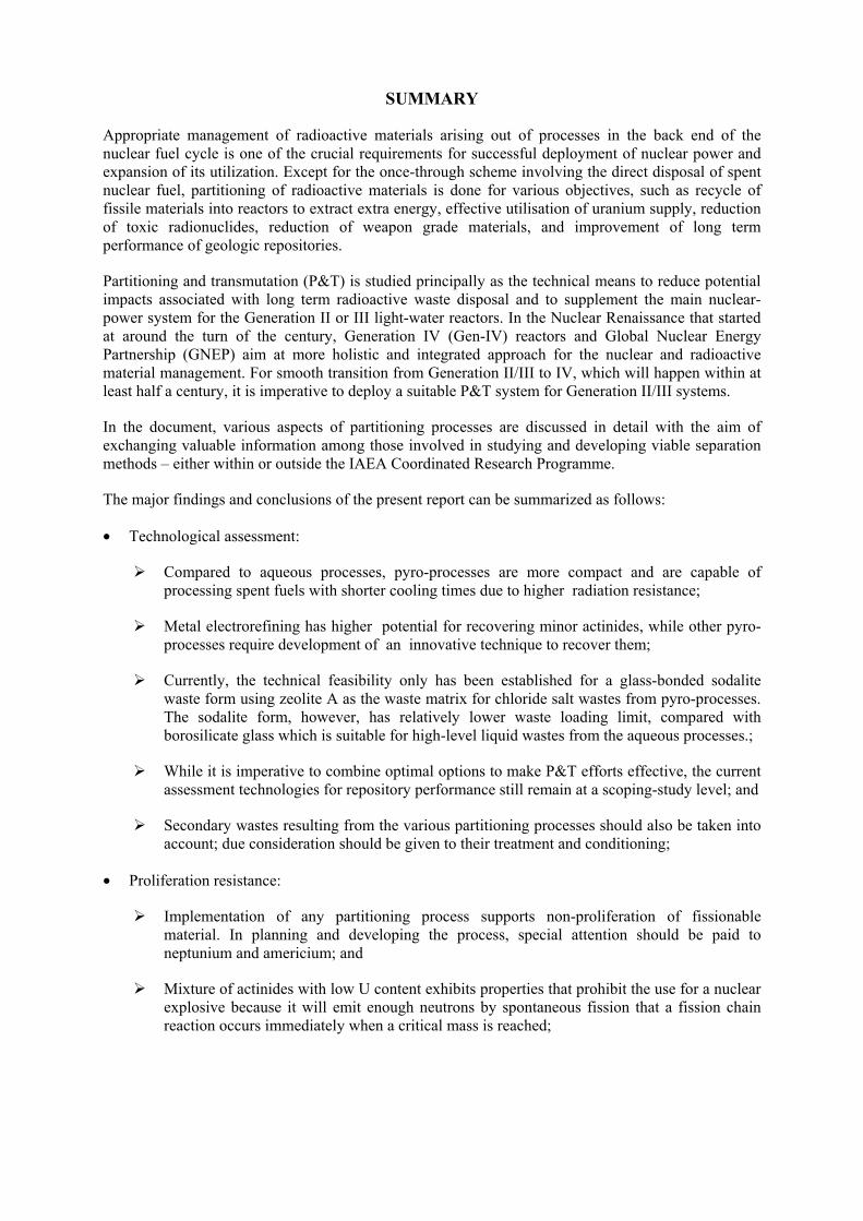
Appropriate management of radioactive materials arising out of processes in the back end of the nuclear fuel cycle is one of the crucial requirements for successful deployment of nuclear power and expansion of its utilization. Except for the once-through scheme involving the direct disposal of spent nuclear fuel, partitioning of radioactive materials is done for various objectives, such as recycle of fissile materials into reactors to extract extra energy, effective utilisation of uranium supply, reduction of toxic radionuclides, reduction of weapon grade materials, and improvement of long term performance of geologic repositories.
Partitioning and transmutation (P&T) is studied principally as the technical means to reduce potential impacts associated with long term radioactive waste disposal and to supplement the main nuclear-power system for the Generation II or III light-water reactors. In the Nuclear Renaissance that started at around the turn of the century, Generation IV (Gen-IV) reactors and Global Nuclear Energy Partnership (GNEP) aim at more holistic and integrated approach for the nuclear and radioactive material management. For smooth transition from Generation II/III to IV, which will happen within at least half a century, it is imperative to deploy a suitable P&T system for Generation II/III systems.
In the document, various aspects of partitioning processes are discussed in detail with the aim of exchanging valuable information among those involved in studying and developing viable separation methods – either within or outside the IAEA Coordinated Research Programme.
The major findings and conclusions of the present report can be summarized as follows:
• Technological assessment:
Compared to aqueous processes, pyro-processes are more compact and are capable of processing spent fuels with shorter cooling times due to higher radiation resistance;
Metal electrorefining has higher potential for recovering minor actinides, while other pyro-processes require development of an innovative technique to recover them;
Currently, the technical feasibility only has been established for a glass-bonded sodalite waste form using zeolite A as the waste matrix for chloride salt wastes from pyro-processes. The sodalite form, however, has relatively lower waste loading limit, compared with borosilicate glass which is suitable for high-level liquid wastes from the aqueous processes.;
While it is imperative to combine optimal options to make P&T efforts effective, the current assessment technologies for repository performance still remain at a scoping-study level; and
Secondary wastes resulting from the various partitioning processes should also be taken into account; due consideration should be given to their treatment and conditioning;
• Proliferation resistance:
Implementation of any partitioning process supports non-proliferation of fissionable material. In planning and developing the process, special attention should be paid to neptunium and americium; and
Mixture of actinides with low U content exhibits properties that prohibit the use for a nuclear explosive because it will emit enough neutrons by spontaneous fission that a fission chain reaction occurs immediately when a critical mass is reached;
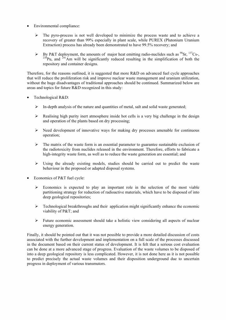
• Environmental compliance:
The pyro-process is not well developed to minimize the process waste and to achieve a recovery of greater than 99% especially in plant scale, while PUREX (Plutonium Uranium Extraction) process has already been demonstrated to have 99.5% recovery; and
By P&T deployment, the amounts of major heat emitting radio-nuclides such as 90Sr, 137Cs-, 238Pu, and 241Am will be significantly reduced resulting in the simplification of both the repository and container designs.
Therefore, for the reasons outlined, it is suggested that more R&D on advanced fuel cycle approaches that will reduce the proliferation risk and improve nuclear waste management and uranium utilization, without the huge disadvantages of traditional approaches should be continued. Summarized below are areas and topics for future R&D recognized in this study:
• Technological R&D:
In-depth analysis of the nature and quantities of metal, salt and solid waste generated;
Realising high purity inert atmosphere inside hot cells is a very big challenge in the design and operation of the plants based on dry processing;
Need development of innovative ways for making dry processes amenable for continuous operation;
The matrix of the waste form is an essential parameter to guarantee sustainable exclusion of the radiotoxicity from nuclides released in the environment. Therefore, efforts to fabricate a high-integrity waste form, as well as to reduce the waste generation are essential; and
Using the already existing models, studies should be carried out to predict the waste behaviour in the proposed or adapted disposal systems.
• Economics of P&T fuel cycle:
Economics is expected to play an important role in the selection of the most viable partitioning strategy for reduction of radioactive materials, which have to be disposed of into deep geological repositories;
Technological breakthroughs and their application might significantly enhance the economic viability of P&T; and
Future economic assessment should take a holistic view considering all aspects of nuclear energy generation.
Finally, it should be pointed out that it was not possible to provide a more detailed discussion of costs associated with the further development and implementation on a full scale of the processes discussed in the document based on their current status of development. It is felt that a serious cost evaluation can be done at a more advanced stage of progress. Evaluation of the waste volumes to be disposed of into a deep geological repository is less complicated. However, it is not done here as it is not possible to predict precisely the actual waste volumes and their disposition underground due to uncertain progress in deployment of various transmutors.
1. INTRODUCTION
1.1. Background information
Partitioning process consists of a range of hydro-metallurgical and / or pyro-chemical procedures, aimed at separation of selected radionuclides or their groups contained primarily in spent nuclear fuels.
Various partitioning methods and techniques represent the front of the overall concept at which back end is transmutation of separated radiotoxic nuclides into shorter-lived or even stable ones. The final effect is twofold: separation of fissionable materials may lead to acquisition of fuels usable in advanced nuclear reactors and, moreover, long term safety of geological repositories – generally - need not be assessed for periods of hundred thousand to million years but only for periods hundred or thousand times shorter. Besides, some nuclides from the fission products´ group can be successfully utilized as catalysts or as strong gamma sources, others (lanthanides) may contribute to enhancement of both, operational safety and proliferation resistance of separated materials.
The aqueous or hydrometallurgical processes developed in the past were seen as an extension of the PUREX process and separated out the minor actinides of the high-level waste by individual processes. The PUREX process uses tri-butyl phosphate (TBP), which generates considerable amounts of medium level waste that are contaminated with long-lived radionuclides. However, with ongoing time, the process has significantly improved in terms of reduced waste generation.
Pyro-chemical separation of transuranium elements has only reached a stage of pilot-plant experiments. These processes were first investigated in the 1950´s as an alternative to PUREX because organic molecules used in PUREX had limited stability in the presence of strong ionizing radiation. In the initial stage, a pyro-chemical process was constructed at the Experimental Breeder Reactor II (EBR-II) in the USA. Later many concepts for pyro-chemical partitioning were developed and, in some cases, pilot plants were built and operated. Presently, electro-refining, electro-winning, fluorination, and molten salt reactors are in the main centre of scientists´ interest.
Certainly, there will be nuclear energy generation considerably more expensive when generated under a P&T scheme than by the present once-through fuel cycle. But in the future, states have to consider other criteria than only cost to achieve a sustainable fuel management strategy: accessibility of U, potential of radionuclide release which may endanger future generations, or misuse of fissile material by sub-national groups. Although U is a rather abundant element, its geographical distribution limits the availability for some states. With respect to national self autarky such states follow already today a breeder program to generate other fissile material than 235U. As regards geological disposal of the radiotoxic waste, there is strong public resistance in most countries for fear of an eventual future release and hazard to coming generations. There exist of course widely thin populated areas on Earth with stable geological formations for radiotoxic waste disposal; however, preferentially sorted out and agreed should be political, financial, ethical and other aspects of such multinational repository project.
The presently used once through fuel cycles require the enrichment of 235U (except for Heavy Water Reactor HWR). This enrichment technology has the possible for military purposes. On contrary, a P&T scheme produces material at all stages that cannot be directly converted into a nuclear explosive. Any diversion of such material – including for terrorist activities - is easily monitored. In future P&T fuel cycles, therefore, international nuclear material safeguards need not longer to verify the compliant operation of enrichment plants, or assure the presence of declared separated Pu, but instead would rather have to monitor the absence of such materials and plants.
Both methods, the aqueous processes and the pyro-chemical ones, have to consider several adverse aspects, which can be briefly summarized as follows:
• Flexibility and simplification of the studied processes; • Process losses; • Proliferation safety; • Decrease of waste volumes; • Reduction of the impact to the environment; and • Costs of facilities to operate partitioning technologies on industrial scale. Flexibility means adaptation to the burn-up conditions, or to the various advanced fuel combinations, whereas simplification means minimum cycles necessary to obtain the desired product. Several new technologies are developed which intend to co-recover of actinides instead of recovering pure individual actinides. For example, in processing TRU-rich fuels that are being developed for futuristic nuclear reactors as well as ADS, a modified IMPUREX process (Improved PUREX process) has been investigated by use of an automatically controlled laboratory scale plant, for which the main objective has been the co-decontamination of uranium and plutonium as a whole after their extraction by TBP, excluding the mutual separation of the two elements.
Evaluation and minimization of process losses is an important task which can make a process more advantageous over that with lower efficiency. Various factors can play an important role in this context: type of fuel, methods of decladding, selection of chemicals, choice of separation procedures, etc.
As regards the proliferation safety, the presently used once through fuel cycles require the enrichment of U-235 (except for HWR). This technology is easily misused for military purposes. In contrary, a P&T scheme produces material at all stages that cannot be directly converted into a nuclear explosive. Any diversion of such material is easily monitored. In future P&T fuel cycles, therefore, international nuclear material safeguards need not longer to verify the compliant operation of enrichment plants, or assure the presence of declared separated Pu, but instead would rather have to monitor the absence of such materials and plants. In addition, despite the beneficial blending of some actinide streams, both types of processes are still vulnerable to the diversion of weapon useable material such as Pu or Np. Various countries try to improve proliferation resistance at all stages of a process; the CEA, France is developing an actinide group extraction process known as ‘Grouped EXtraction of ActiNide’ (GANEX). China Institute of Atomic Energy (CIAE) Beijing, China is supplementing and comparing the aqueous partitioning approaches as a contribution to the CRP.
The overall efficiency of partitioning and transmutation (P&T) processes [1] in multiple recycling of plutonium and minor actinides (MAs) would determine the limits of P&T in minimization radiotoxicity of residual radioactive waste [2]. The potential reduction in the environmental impact by several scenarios of P&T involving conventional light water reactors (LWRs) to advanced nuclear reactors such as fast neutron reactor or accelerator-driven sub-critical reactors (ADS) have been recently analyzed by OECD/NEA [3], [4] and the IAEA [5]. In this context, different fuel cycle strategies other than the once through fuel cycle, are being developed, viz.: • use of fast reactors to burn Pu generated from LWR; • use of fast reactors to burn Pu and MAs generated from LWR; • use of fast reactor to recycle transuranic isotopes (TRUs) and reprocessed U from LWR; • use of only fast reactors i.e., replacement of all LWRs with fast reactors; • use of ADS to reduce TRUs and reprocessed U from LWRs; and • ‘Double-Strata Concept’ i.e., collective use of fast reactor and accelerators to deal with the all
TRUs and reprocessed U as well as some long-lived fission products. These strategies are under active consideration by different Member States according to their national preferences. Moreover some are also examining alternate fuel cycle concepts such as thorium fuel cycle [6] in which MA generation is minimized, use of fertile-free inert matrix fuels for transmutation of Pu and the minor actinides [7].
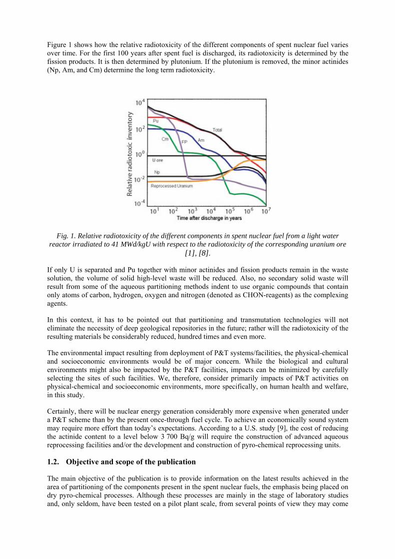
Figure 1 shows how the relative radiotoxicity of the different components of spent nuclear fuel varies over time. For the first 100 years after spent fuel is discharged, its radiotoxicity is determined by the fission products. It is then determined by plutonium. If the plutonium is removed, the minor actinides (Np, Am, and Cm) determine the long term radiotoxicity.
Fig. 1. Relative radiotoxicity of the different components in spent nuclear fuel from a light water reactor irradiated to 41 MWd/kgU with respect to the radiotoxicity of the corresponding uranium ore
[1], [8].
If only U is separated and Pu together with minor actinides and fission products remain in the waste solution, the volume of solid high-level waste will be reduced. Also, no secondary solid waste will result from some of the aqueous partitioning methods indent to use organic compounds that contain only atoms of carbon, hydrogen, oxygen and nitrogen (denoted as CHON-reagents) as the complexing agents.
In this context, it has to be pointed out that partitioning and transmutation technologies will not eliminate the necessity of deep geological repositories in the future; rather will the radiotoxicity of the resulting materials be considerably reduced, hundred times and even more.
The environmental impact resulting from deployment of P&T systems/facilities, the physical-chemical and socioeconomic environments would be of major concern. While the biological and cultural environments might also be impacted by the P&T facilities, impacts can be minimized by carefully selecting the sites of such facilities. We, therefore, consider primarily impacts of P&T activities on physical-chemical and socioeconomic environments, more specifically, on human health and welfare, in this study.
Certainly, there will be nuclear energy generation considerably more expensive when generated under a P&T scheme than by the present once-through fuel cycle. To achieve an economically sound system may require more effort than today’s expectations. According to a U.S. study [9], the cost of reducing the actinide content to a level below 3 700 Bq/g will require the construction of advanced aqueous reprocessing facilities and/or the development and construction of pyro-chemical reprocessing units.
1.2. Objective and scope of the publication
The main objective of the publication is to provide information on the latest results achieved in the area of partitioning of the components present in the spent nuclear fuels, the emphasis being placed on dry pyro-chemical processes. Although these processes are mainly in the stage of laboratory studies and, only seldom, have been tested on a pilot plant scale, from several points of view they may come
in useful in the application of advanced separation methods prior to transmutation, rather than the aqueous methods.
These aspects include proliferation resistance of separated components, waste formation and the environmental impact; the other way round, as a drawback can be seen process losses from various separation methods. In the document, all these aspects are discussed in detail with the aim of exchanging valuable information among those involved in studying and developing - either within or outside the IAEA coordinated research programme - a viable separation method.
In this report the aqueous methods are dealt with only marginally to facilitate a comparison between the two basic methods. Not considered are effects of non-radioactive and/or chemotoxic materials. Beyond the scope is also a more detailed description of various transmutation technologies.
1.3. Structure of the publication
Following this introductory part, Section 2 contains a brief description of the aqueous processes, i.e.: the PUREX process and its later variations. Section 3 summarizes background information about pyro-processes, whereas Section 4 is dedicated to waste forms in which the process materials are incorporated. Section 5 deals with process losses whereas the next Section 6 is dedicated to the problems of proliferation resistance. Section 7 contains discussion of potential environmental impacts and tries to compare planned geological repositories for non-reprocessed fuel with those for waste resulting from a complete partitioning and transmutation process. Critical radionuclides are dealt with in Section 8 and a discussion with conclusions and recommendations for further studies is presented in Section 9. The report is supplemented with annexes, references, list of abbreviations, and a list of persons participating in preparation of this report.
2. AQUEOUS PROCESSES FOR PARTITIONING AND TRANSMUTATION
It has been previously mentioned that advanced aqueous processes are variants of the original PUREX process used for recovering uranium and plutonium from LWR type spent nuclear fuel. The major difference among these methods rests on the nature of the separated product stream. They tend to separate either all the actinides together, all the actinides except uranium together, the minor actinides, or the fission products of concern such as I, Tc, and Cs.
Besides separation of U and Pu according to the typical scheme, these advanced processes involve the following steps:
• recovering minor actinides (MA) and lanthanide fission products; • purifying the MAs from the lanthanides; • individually separating MAs; and • recovering individual radionuclides. The aqueous methods are discussed here briefly.
2.1. Process PUREX (industrial scale)
The only reprocessing method developed up to plant scale and employed worldwide in all the commercial plants is the PUREX (Plutonium-Uranium Extraction) process. For aqueous reprocessing processes there are two different lines of approach:
(i) advanced separation of different components in the high level liquid waste (HLLW) generated by the PUREX process (advanced separation), or
(ii) alternate advanced processes to PUREX by changing the chemistry in the first separation step so that only uranium is separated, while keeping plutonium, minor actinides and fission products in the waste solution for later processing (e.g., Uranium Extraction Process UREX).
Such reagents can be burned completely and will thus result in relatively lesser volumes of solid wastes. The selectivity of TBP for U and Pu made PUREX process as the prime reprocessing technology. However, TBP could not be utilized for recovering trivalent actinides namely Np, Am and Cm. For the advanced partitioning methods that are being developed for removing MAs from HLLW, very high separation efficiency for MAs is required to reduce the long term radiotoxicity of remnant HLLW by a significant factor. Considering the PUREX as the reference reprocessing technology, the goal of the MA partitioning step should be a separation efficiency of 99.9% (i.e. a decrease of the TRU content in HLLW by a factor of 1000). The MAs to be considered are neptunium, americium and curium, which are present in a strong nitric acid solution (~3M HNO3) of the high active raffinate stream. The recovery of MA fraction entails co-recovery of the lanthanide elements, also called as rare earths (REs), which are, in terms of quantity, about 10–20 times more abundant than the minor actinides, depending on the burn-up. At 45 GWd/t HM the ratio is 16:1 (13.9 kg rare earth compared with 0.870 kg of americium and curium per t HM of spent fuel.
Following the successful management of the PUREX process, several processes have been studied and tested in hot facilities; among the most important are the ‘TRansUranium EXtraction’ (TRUEX), ‘di-isodecylphosphoric acid’ (DIDPA), ‘TRi-alkyl PhOsphine’ (TRPO) and ‘DIAMide EXtraction’ (DIAMEX) processes for actinide–lanthanide group separation, coupled to the CYANEX 301, ‘Selective ActiNide Extraction’ (SANEX), ‘Actinide - Lanthanide INtergroup separation in Acidic medium’ (ALINA) and BTP (bis-triazinyl-1, 2, 4-pyridines) processes, which allow actinide–lanthanide separation. Some of these salient advanced aqueous partitioning processes are being currently developed and are extensively covered in the attached literature [5], [6], [10], [11], [12], [13], [14], [15], [16], [17], [18], [19].
Moreover, these technologies could address transuranic recovery in the clean-up of nuclear legacy wastes and residues; as well different wastes arising from conventional fuel cycle facilities. Thus these new processing technologies would enhance recovery of radio-toxic elements which otherwise would have been destined for waste disposal which includes decommissioned facility. It is worth-noting that technology development of the waste-processing and clean-up often has common R&D issues with the future fuel cycle development which includes proliferation-resistant fuel cycle technologies. There is therefore benefit in developing flexible, simplified and intensified separation flow-sheets that handle a wide range of HLLW with minimized processing costs and waste generation that could be operated from miniature plant scale.
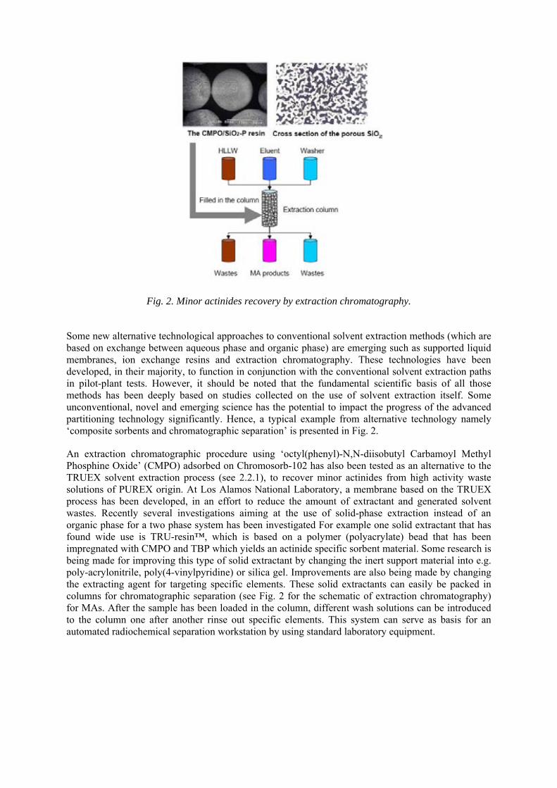
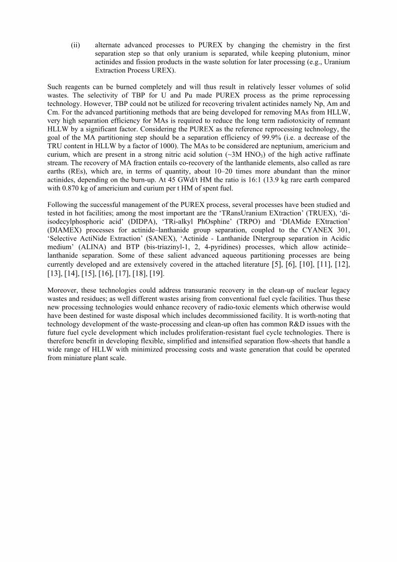
Fig. 2. Minor actinides recovery by extraction chromatography.
Some new alternative technological approaches to conventional solvent extraction methods (which are based on exchange between aqueous phase and organic phase) are emerging such as supported liquid membranes, ion exchange resins and extraction chromatography. These technologies have been developed, in their majority, to function in conjunction with the conventional solvent extraction paths in pilot-plant tests. However, it should be noted that the fundamental scientific basis of all those methods has been deeply based on studies collected on the use of solvent extraction itself. Some unconventional, novel and emerging science has the potential to impact the progress of the advanced partitioning technology significantly. Hence, a typical example from alternative technology namely ‘composite sorbents and chromatographic separation’ is presented in Fig. 2.
An extraction chromatographic procedure using ‘octyl(phenyl)-N,N-diisobutyl Carbamoyl Methyl Phosphine Oxide’ (CMPO) adsorbed on Chromosorb-102 has also been tested as an alternative to the TRUEX solvent extraction process (see 2.2.1), to recover minor actinides from high activity waste solutions of PUREX origin. At Los Alamos National Laboratory, a membrane based on the TRUEX process has been developed, in an effort to reduce the amount of extractant and generated solvent wastes. Recently several investigations aiming at the use of solid-phase extraction instead of an organic phase for a two phase system has been investigated For example one solid extractant that has found wide use is TRU-resin™, which is based on a polymer (polyacrylate) bead that has been impregnated with CMPO and TBP which yields an actinide specific sorbent material. Some research is being made for improving this type of solid extractant by changing the inert support material into e.g. poly-acrylonitrile, poly(4-vinylpyridine) or silica gel. Improvements are also being made by changing the extracting agent for targeting specific elements. These solid extractants can easily be packed in columns for chromatographic separation (see Fig. 2 for the schematic of extraction chromatography) for MAs. After the sample has been loaded in the column, different wash solutions can be introduced to the column one after another rinse out specific elements. This system can serve as basis for an automated radiochemical separation workstation by using standard laboratory equipment.
2.2. Processes for co-extraction of actinides and lanthanides
2.2.1. TRUEX process
The TRUEX (TRansUranium EXtraction) process was developed in USA in 80’s and is based on the use of ‘octyl(phenyl)-N,N-diisobutyl Carbamoyl Methyl Phosphine Oxide’ (CMPO) as the extractant. In this process, extracted are both the actinides and lanthanides, together from acidic feeds. The process was studied in USA, Japan, Russian Federation, Italy and India and thus, large experience exists in the world. It also has been tested with actual high level waste (HLW) and proved very efficient. However, the process suffers from the disadvantage that large concentration of n-tributyl phosphate has to be used as the modifier to avoid third phase formation. Efficiency of stripping of metal ions is not reportedly very high. The clean up of the solvent is also considered a problem.
2.2.2. DIAMEX process
The PUREX process uses a phosphor-based organic compound, which generates considerable amounts of medium level waste contaminated with long-lived radionuclides. Therefore, the new aqueous partitioning method indent to use organic compounds that contain only atoms of carbon, hydrogen, oxygen and nitrogen (denoted as C,H,O,N-reagents) as the complexing agents. Such reagents can completely be burned and will thus result in relatively lesser volumes of solid wastes. Considering the C, H, O, N principle, CEA, France, developed the DIAMEX (DIAMide EXtraction) process. It uses malonamide as the extractant and co-extracted from acidic feeds are also actinides and lanthanides here. The efficiency of the process has been demonstrated by testing with actual high level waste solutions (HLW) in France and Europe. The disadvantage of the method is the partial co-extraction of noble metals Pd and Ru along with minor actinides.
2.2.3. TRPO process
The TRPO (TRi-alkyl PhOsphine) process has been developed and tested with actual HAW in China. It employs a mixture of tri-alkyl phosphine oxides (R3P(O), with R = alkyl groups) as the extractant. Its major disadvantage is the need to use concentrated nitric acid solution for stripping actinides and lanthanides, which could complicate the next stage of separating the two groups.
2.2.4. ARTIST process
The ARTIST (Amide-based Radio-resources Treatment with Interim Storage of Transuranics) process is developed by the Japan Atomic Energy Agency (JAEA), Japan (see Fig. 3). It envisages the separation of uranium from the spent fuel as the first step so that the process volume is brought down. Then TRUs are separated as a group along with lanthanides by using the extractants, TODGA (Tetra-octyl-diglycol-amide) and DHOA (di-n-hexyl-octanamide). The process offers flexibility in terms of various options – to separate Cs and Sr, or achieve the separation of lanthanides and TRUs, or separate plutonium from the TRU stream by using the DHOA process.
.
Fig. 3. Schematic of the ARTIST process.
2.3. Processes for actinide-lanthanide separation
2.3.1. TALSPEAK and CTH processes
The TALSPEAK (Trivalent Actinide Lanthanide Separations by Phosphorus-reagent Extraction from Aqueous Komplexes) process was developed at ORNL, USA in the sixties. The process was adopted as CTH (Chalmers Tekniska Hogskola) process in Sweden. It employs di-2-ethyl-hexyl-phosphoric acid (HDEHP) to extract actinides and lanthanides together and then, from HDEHP containing these two groups of elements, diethylene-triamine-penta-acetic acid (DTPA) is used to extract trivalent actinides by complexation. It is done by equilibrating HDEHP with an aqueous solution containing DTPA and a hydroxocarboxylic acid, like lactic, glycolic or citric acids. There is also large experience with this process in many countries. Besides the difficulty encountered in solvent clean up, the disadvantages include the need for adjusting the pH of the feed and the limited loading of metal ions in the solvent.
2.3.2. SANEX process
The SANEX process (Selective ActiNide Extraction) is a generic name for a process, which separates selectively the trivalent actinides (viz., americium and curium) from the lanthanides in the highly acidic waste feeds. These processes could be categorized in two distinct groups based on the chemical nature of the extractant namely: i) acidic S-bearing extractants; and ii) neutral N bearing extractants.
2.3.2.1. Cyanex 301 process (Acidic S-bearing extractants)
Cyanex represents compounds which belong to the family of organo-dithio-phosphinates (R2PSSH, with R = an alkyl group) and CYANEX – 301. This process was developed in China in 1995 and uses a mixture consisting mainly of bis (2.4.4. – trimethylpentyl) dithiophosphinic acid. Though the process has been tested for its high efficiency using actual lanthanide-actinide mixtures, it also suffers from the disadvantage of the need for adjusting the pH of the feed to 3 to 5. Solvent cleanup is also difficult.
2.3.2.2. ALINA process (Acidic S-bearing extractants)
The ALINA (Actinide - Lanthanide INtergroup separation in Acidic medium) process was developed in Germany. It uses of a syngergistic mixture of bis(chlorophenyl)dithio-phosphinic acid ((ClΦ)2PSSH) and tri-n-octylphosphine oxide (TOPO). The major advantage of the process is that if needed, the concentration of nitric acid in the feed can be increased to as high a value as 1.5 mol/L to increase the separation efficiency of lanthanides and actinides. It has also been tested with actual HLWs. However, the solvent clean up procedure for the process has not been defined yet. Another major disadvantage of the process is that the degradation products of the solvent result in P and S containing wastes.
2.3.2.3. Processes using BTPs (neutral N bearing extractants)
It was established in Germany that bis-triazinyl-1, 2, 4-pyridines (BTPs) have very good efficiency for Am(III)/Ln(III) separation and thus, a process was readily developed under the NEWPART project of European programme. Using n-propyl-BTP, the process was successfully tested in France and Germany. The advantage of the process is that the feed can be acidic (1mol/L of HNO3). However, since instability of the n-propyl-BTP, methods of overcoming the problem are being studied in CEA, France.
Process using TMAHDPTZ+octanoic acid (neutral N bearing extractants)
This process developed in France is based on a synergistic mixture of terdendate N-ligand, 2-(3, 5, 5-trimethylhexanoylamino)- 4, 6-di-(pyridin-2-yl)-1, 3, 5-triazine (TMAHDPTZ), and octanoic acid. Though the efficiency of the process has been demonstrated with actual HLWs, the need for adjusting the pH is a disadvantage of this process. In addition, the method of management of secondary waste has not been developed, too.
2.4. Processes for Am/Cm separation
2.4.1. SESAME process
SESAME (Selective Extraction and Separation of Americium by Means of Electrolysis) is based on the selective oxidation of Am(III) to higher valent state followed by extraction, using solvent to achieve separation from Cm(III). In the method developed in France, the oxidation of Am(III) to Am(VI) was achieved by electrolysis in the presence of heteropolyanions (HPA) as catalyst and then, Am(VI) was extracted by TBP (tributyl phosphate). However, the process variant developed in Japan, uses ammonium persulphate to oxidize Am(III) to Am(VI). Though the efficacy of the process has been amply demonstrated in CEA, France, wherein kg amounts of purified 241Am have been obtained, the instability of Am(VI), the difficulties in making it a multistage process and the secondary waste containing HPA constituents pose a big challenge for industrialization of the process.
2.4.2. Am(V) precipitation process
This simple process, developed in USA in sixties, is based on the precipitation of a double carbonate of Am(V) and potassium. In this method, the mixture of Am(III) and Cm(III) is dissolved in a 2 mol/L K2CO3 solution and then, Am(III) is oxidized by chemical or electrochemical means to Am(V), which precipitates from the solution as solid crystalline K5AmO2(CO3)3 nH2O, while Cm(III) remains in the solution. Americium is separated from curium by filtration. The process has been used worldwide and is very selective for Am. However, the losses of Am proved to be significant. The difficulty in making it a multistage process and the amount of secondary waste generated are additional disadvantages of the process.
It is necessary to point out that the above processes are multi-cycle processes.
2.5. Processes for minor actinide partitioning
2.5.1. DIDPA process
This process was developed in JAEA, Japan. It is based on the use of di-isodecylphosphoric acid (DIDPA). The separation of the TRU elements is done by successive stripping from the loaded solvent, including the use of diethylenetriaminopentaacetic acid (DTPA) complexing agent for actinides(III)/Ln(III) separation (as is done in TALSPEAK process). The process has been successfully tested in hot cell in Japan. However, the need for feed acidity adjustment and the limited metal ion loading in the solvent are the major disadvantages besides the degradation of the solvent.
2.5.2. SETFICS process
SETFICS (Solvent Extraction for Trivalent f-elements Intra-group Separation in CMPO-complexant System) process could be considered as a modified TRUEX process, as is also based on the same solvent CMPO. It also envisages the use of DTPA for separation of actinides and lanthanides. The process has not been tested with actual HAWs. It reportedly has limited stripping efficiency. Management of effluents containing DTPA and the salts is another area of concern.
2.5.3. PALADIN process
PALADIN is the acronym of ‘Partition of Actinides and Lanthanides with Acidic extractant, Diamide and INcinerable’ complexants. PALADIN is a one partition cycle process able to separate directly americium and curium from lanthanides (Ln) and other fission products mixed in concentrated nitric acid (similar to a PUREX raffinate). This process, developed in France, is based on the use of a mixture of extractants: a malonamide (DIAMEX process extractant)+di-ethylhexylphosphoric acid (HDEHP), and the extractant of the TALSPEAK process.
2.6. Processes for fission product partitioning
2.6.1. Iodine (129I)
In the PUREX process, once the fuel is dissolved, the iodide ion (I-) is oxidized to elemental iodine, wherein it gets into the dissolver off-gases, from which the recovery is done by washing with basic solution.
2.6.2. Technetium (99Tc)
During the dissolution step of the PUREX process, only part of the fission product technetium is dissolved and the rest remains a solid in the insoluble residue. At present, process step is known for the recovery of the soluble fraction. The soluble fraction remaining as Tc(VII) (TcO4
-) is extracted by TBP along with Zr(IV), U(VI) and Pu(IV). The recovery of this soluble fraction is done through a special scrubbing step in the reprocessing plant at AREVA (formerly COGEMA), La Hague, France.
2.6.3. Caesium and strontium
Various countries have developed different processes based on the use of different extractants for the recovery of caesium and strontium. The four group partitioning process developed in Japan uses inorganic sorbents whereas the SREX (Sr Extraction) and CSEX (Cs Extraction) processes developed in USA rely on the use of organic crown–ether reagents. Cobalt dicarbollide extractants based processes (CCD-PEG) were developed in the Czech Republic, Russian Federation, and Western Europe. Calix-crown extractants based process, developed in France, Western Europe, and the USA, is also known. Most of these processes were successfully tested with radioactive effluents.
2.7. Combined processes
Many processes are known for the co-extraction or separation of the desired metal ions. Combining these processes to evolve a flow sheet, which addresses their own interest, is the strategy adopted by various countries.
Some creative methods have considered the use of aqueous complexants such as hydroxamic acid derivatives which prevent extraction of both elements by TBP by complexation of Np(IV) and Pu(IV) and un-affecting U(VI) extraction. This gave birth to the development of Uranium Extraction Process (UREX) which utilizes aceto-hydroxamic acid (AHA).
For example, the development of a set of processes known as UREX+ (URanium EXtraction processes is of current interest. The UREX+ process is a series of five solvent-extraction flowsheets, which perform the following operations: (1) recovery of Tc and U (UREX); (2) recovery of Cs and Sr (CCD-PEG); (3) recovery of Pu and Np (NPEX for Np extraction); (4) recovery of Am, Cm, and rare-earth fission products (TRUEX); and finally (5) separation of Am and Cm from the rare earths (Cyanex 301). These processes are used in combination with pyro-processes. They are aimed at the extraction of U only, whereas for TRU extraction from the UREX process waste, pyro-processes are considered.
This UREX based separation process has become one of the key attribute in the development plan of US-DOE’s ‘Advanced Fuel Cycle Initiative’ (AFCI), which is the fundamental technical edifice for the development ‘Global Nuclear Energy Partnership’ (GNEP). The primary ability of UREX process is to separate pure uranium which constitutes as the bulk of the mass of the spent fuel lead to the road-map of development separating heat-generating radio-nuclides such as cesium and strontium.
The strategy adopted by CEA, France, is based on the use of successive liquid –liquid extraction processes. The first stage will be the extraction of U, Pu, Np, I, and Tc, using improved PUREX process. DIAMEX process will be used for extracting Am+Cm during which lanthanides will be co-extracted and the separation of lanthanides and minor actinides (Am+Cm) will be achieved using SANEX process. Separation of Am and Cm will be carried out by using the SESAME process. France will use the calixcrown process for separating Cs. However in the USA, Japan, the Czech Republic or the Russian Federation, instead of using successive separation processes, an integrated scheme of processes for MAs and FPs extraction are studied such as the combined extraction of Cs+Sr+(Am+Cm)+Ln by using a mixture of cobalt dicarbollide and dioxide of diphosphine.
France has also developed the COEX (CO-EXtraction of actinides) process based on the co-extraction and co-precipitation of uranium and plutonium together as well as a pure uranium stream to ensure that no pure plutonium is separated. A possible variation could be the extraction of neptunium along with U and Pu. This is designed for Generation III recycling plants and is close to near-term industrial deployment; it also allows high MOX performance for both light-water and fast reactors.
The GANEX (Grouped EXtraction of ActiNides) process co-precipitates some uranium with the plutonium (as with COEX), but then separates actinides and some lanthanides from the short-lived fission products. The uranium, plutonium and minor actinides together become fuel in Generation IV fast neutron reactors, whereas the lanthanides become waste. It should be demonstrated at La Hague from 2008 as part of a French-Japanese-US global actinide cycle international demonstration.
All the three processes namely, COEX, GANEX and the DIAMEX-SANEX should be assessed by 2012 so that these can be industrially employed by 2020.
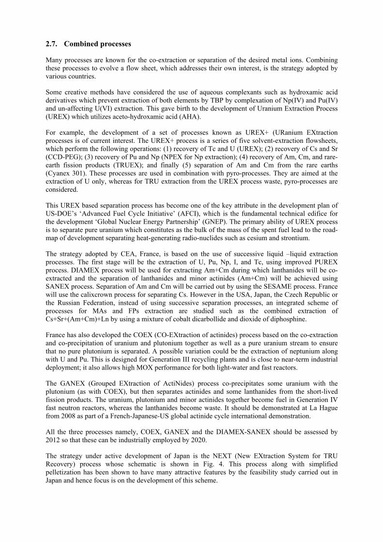
The strategy under active development of Japan is the NEXT (New EXtraction System for TRU Recovery) process whose schematic is shown in Fig. 4. This process along with simplified pelletization has been shown to have many attractive features by the feasibility study carried out in Japan and hence focus is on the development of this scheme.
The process envisages separation of U by crystallization so as to reduce the process volume and then the co-extraction of U, Pu and Np, and an extraction step of MA (Am, Cm) by the extraction chromatography.
Fig. 4. Schematic diagram of the NEXT process.
In Japan, the Supercritical fluid DIRect EXtraction system called ‘Super-DIREX’ is also being considered as a candidate for development. In this process, fuel materials are directly extracted into a supercritical fluid carbon dioxide-TBP-nitric acid mixture from powdered spent fuel. Though the process appears to be simple and promising, its potential has to be substantiated by many studies.
In India, since nineties, R&D on minor actinide partitioning has been carried out. Basic data were generated for the extraction of actinides and a few fission and corrosion products using TRUEX solvent (0.2M CMPO-1.2M TBP in n-dodecane). Extensive studies have also been carried out on the extraction of actinides from synthetic and actual high-level aqueous raffinate waste (HLLW), sulphate bearing at low acidity of about 0.3M, non-sulphate wastes originating from pressurized heavy water reactor (PHWR) and fast breeder reactor (FBR) both in 3M HNO3, and actual HLW solutions generated from the reprocessing of research reactor fuels. Several higher homologues of TBP such as triisoamyl phosphate, tri-n-amyl phosphate, tri-2-methyl-1-butyl phosphate, and tri-n-hexyl phosphate, have been synthesised in house, characterised and their suitability for reprocessing applications assessed. These phosphates are devoid of problems associated with TBP such as high aqueous phase solubility and third phase formation. Long chain dialkyl monamides have been developed and suggested as extractants for thermal reactor reprocessing due to advantageous properties such as; 1) complete incinerability; 2) easy partitioning with mere acidity variation; and 3) formation of non deleterious degradation products, etc.
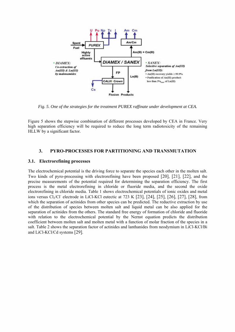
Fig. 5. One of the strategies for the treatment PUREX raffinate under development at CEA.
Figure 5 shows the stepwise combination of different processes developed by CEA in France. Very high separation efficiency will be required to reduce the long term radiotoxicity of the remaining HLLW by a significant factor.
3. PYRO-PROCESSES FOR PARTITIONING AND TRANSMUTATION
3.1. Electrorefining processes
The electrochemical potential is the driving force to separate the species each other in the molten salt. Two kinds of pyro-processing with electrorefining have been proposed [20], [21], [22], and the precise measurements of the potential required for determining the separation efficiency. The first process is the metal electrorefining in chloride or fluoride media, and the second the oxide electrorefining in chloride media. Table 1 shows electrochemical potentials of ionic oxides and metal ions versus Cl2/Cl- electrode in LiCl-KCl eutectic at 723 K [23], [24], [25], [26], [27], [28], from which the separation of actinides from other species can be predicted. The reductive extraction by use of the distribution of species between molten salt and liquid metal can be also applied for the separation of actinides from the others. The standard free energy of formation of chloride and fluoride with relation to the electrochemical potential by the Nernst equation predicts the distribution coefficient between molten salt and molten metal with a function of molar fraction of the species in a salt. Table 2 shows the separation factor of actinides and lanthanides from neodymium in LiCl-KCl/Bi and LiCl-KCl/Cd systems [29].
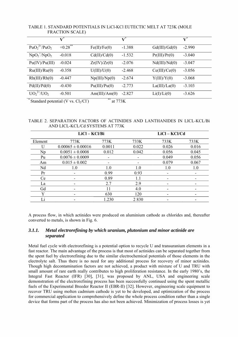
TABLE 1. STANDARD POTENTIALS IN LiCl-KCl EUTECTIC MELT AT 723K (MOLE FRACTION SCALE)
V* V* V*
PuO22+/PuO2 +0.28** Fe(II)/Fe(0) -1.388 Gd(III)/Gd(0) -2.990
NpO2+/NpO2 -0.018 Cd(II)/Cd(0) -1.532 Pr(III)/Pr(0) -3.040
Pu(IV)/Pu(III) -0.024 Zr(IV)/Zr(0) -2.076 Nd(III)/Nd(0) -3.047
Ru(III)/Ru(0) -0.358 U(III)/U(0) -2.468 Ce(III)/Ce(0) -3.056
Rh(III)/Rh(0) -0.447 Np(III)/Np(0) -2.674 Y(III)/Y(0) -3.068
Pd(II)/Pd(0) -0.430 Pu(III)/Pu(0) -2.773 La(III)/La(0) -3.103
UO22+/UO2 -0.501 Am(III)/Am(0) -2.827 Li(I)/Li(0) -3.626
* Standard potential (V vs. Cl2/Cl-) ** at 773K
TABLE 2. SEPARATION FACTORS OF ACTINIDES AND LANTHANIDES IN LICL-KCL/Bi AND LICL-KCL/Cd SYSTEMS AT 773K
LiCl – KCl/Bi LiCl – KCl/Cd
Element 773K 773K 733K 733K 733K U 0.00065 ± 0.00016 0.0011 0.022 0.026 0.016
Np 0.0051 ± 0.0008 0.012 0.042 0.056 0.045 Pu 0.0076 ± 0.0009 - - 0.049 0.056 Am 0.015 ± 0.002 - - 0.079 0.067 Nd 1.0 1.0 1.0 1.0 1.0 Pr - 0.99 0.93 - - Ce - 0.89 1.1 - - La - 2.7 2.9 - - Gd - 11 4.0 - - Y - 630 120 - - Li - 1.230 2 830 - -
A process flow, in which actinides were produced on aluminium cathode as chlorides and, thereafter converted to metals, is shown in Fig. 6.
3.1.1. Metal electrorefining by which uranium, plutonium and minor actinide are separated
Metal fuel cycle with electrorefining is a potential option to recycle U and transuranium elements in a fast reactor. The main advantage of the process is that most of actinides can be separated together from the spent fuel by electrorefining due to the similar electrochemical potentials of those elements in the electrolyte salt. Thus there is no need for any additional process for recovery of minor actinides. Though high decontamination factors are not achieved, a product with mixture of U and TRU with small amount of rare earth really contributes to high proliferation resistance. In the early 1980’s, the Integral Fast Reactor (IFR) [30], [31], was proposed by ANL, USA and engineering scale demonstration of the electrorefining process has been successfully continued using the spent metallic fuels of the Experimental Breeder Reactor II (EBR-II) [32]. However, engineering scale equipment to recover TRU using molten cadmium cathode is yet to be developed, and optimization of the process for commercial application to comprehensively define the whole process condition rather than a single device that forms part of the process has also not been achieved. Minimization of process losses is yet
another issue to be addressed. Central Research Institute of Electric Power Industry (CRIEPI) has been involved in developing this technology since the middle of 1980s [33], [34]. After determining the thermodynamic properties of actinides and rare earths in LiCl-KCl [35], verification of separation with actual material is currently in progress [36]. Other current activities are generation of data for designing an engineering scale equipment [37], [38], and for management of the fissile material in the process to ensure the safe-guardability by establishing an accounting method. Korea Atomic Energy Research Institute, (KAERI) is also setting up an engineering scale demonstration facility [39]. Besides these countries, India and the P.R. of China are also working on the development of this technology.
The ‘Global Nuclear Energy Partnership’ (GNEP) programme announced in 2006 by the US-DOE (Department of Energy of USA) supports new methods for recycling spent nuclear fuel, in which pyro-processing is positioned as the potential potion for the generation-IV nuclear system. On this background, an engineering scale model of electrorefiner has successfully achieved to collect uranium metal onto the solid cathode with kg scale, and the plutonium recovery into liquid cadmium cathode has started by use of a small scale electrorefiner equipped in a hot cell. CRIEPI also adopted a reductive extraction to recover actinides from the salt used at electrorefining as well as an electrorefining for main separation process of actinides. Hot-cell experiments using a genuine material have been conducting to verify TRU recover into a liquid cadmium as well as uranium collection onto a solid cathode. The metal electrorefining has an advantage that no additional process is required to separate minor actinides when a liquid metal cathode, such as cadmium or bismuth, is applied, because of similar electrode potentials by taking activity coefficients of species in liquid metals into account.
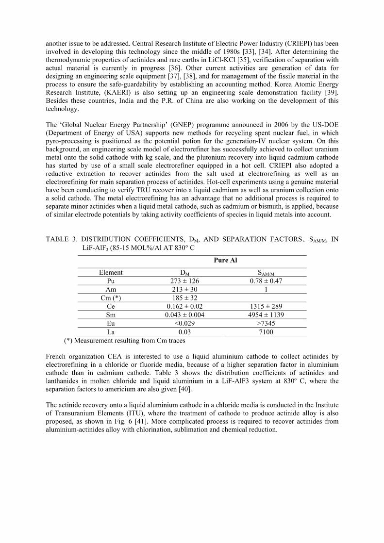
TABLE 3. DISTRIBUTION COEFFICIENTS, DM, AND SEPARATION FACTORS、SAM/M, IN LiF-AlF3 (85-15 MOL%/Al AT 830° C
Pure Al
Element DM SAM/M Pu 273 ± 126 0.78 ± 0.47 Am 213 ± 30 1
Cm (*) 185 ± 32 Ce 0.162 ± 0.02 1315 ± 289 Sm 0.043 ± 0.004 4954 ± 1139 Eu <0.029 >7345 La 0.03 7100
(*) Measurement resulting from Cm traces
French organization CEA is interested to use a liquid aluminium cathode to collect actinides by electrorefining in a chloride or fluoride media, because of a higher separation factor in aluminium cathode than in cadmium cathode. Table 3 shows the distribution coefficients of actinides and lanthanides in molten chloride and liquid aluminium in a LiF-AlF3 system at 830º C, where the separation factors to americium are also given [40].
The actinide recovery onto a liquid aluminium cathode in a chloride media is conducted in the Institute of Transuranium Elements (ITU), where the treatment of cathode to produce actinide alloy is also proposed, as shown in Fig. 6 [41]. More complicated process is required to recover actinides from aluminium-actinides alloy with chlorination, sublimation and chemical reduction.
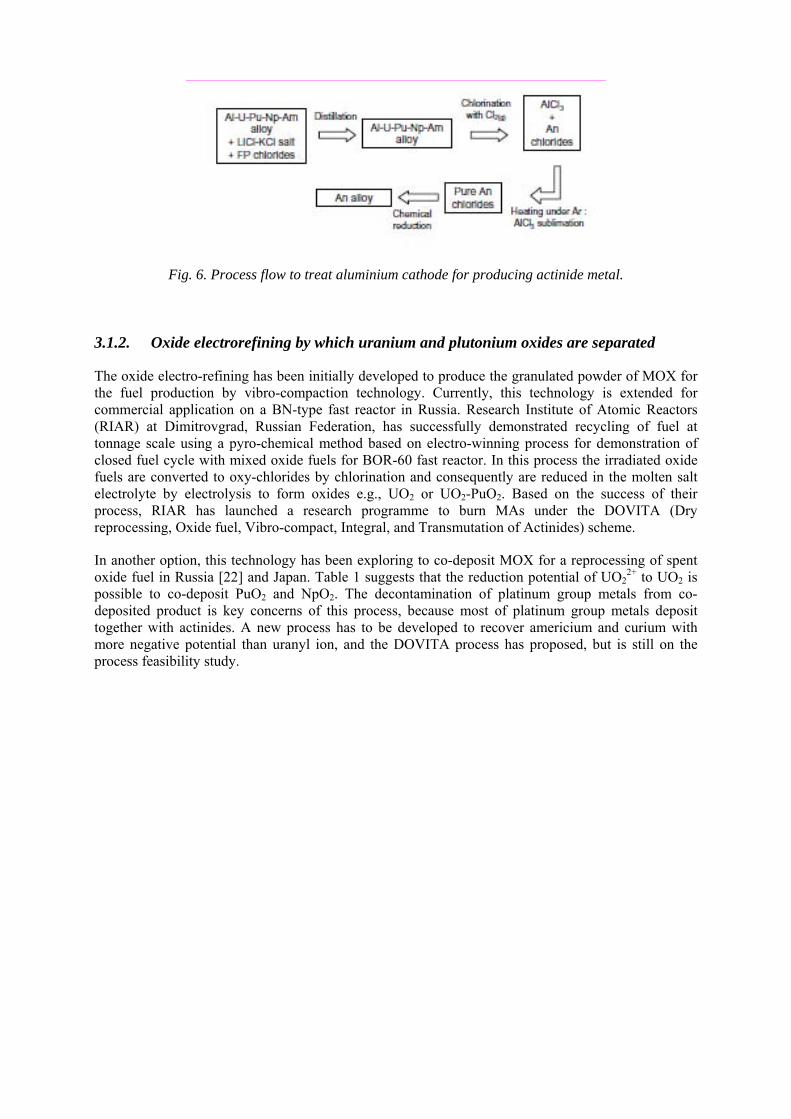
Fig. 6. Process flow to treat aluminium cathode for producing actinide metal.
3.1.2. Oxide electrorefining by which uranium and plutonium oxides are separated
The oxide electro-refining has been initially developed to produce the granulated powder of MOX for the fuel production by vibro-compaction technology. Currently, this technology is extended for commercial application on a BN-type fast reactor in Russia. Research Institute of Atomic Reactors (RIAR) at Dimitrovgrad, Russian Federation, has successfully demonstrated recycling of fuel at tonnage scale using a pyro-chemical method based on electro-winning process for demonstration of closed fuel cycle with mixed oxide fuels for BOR-60 fast reactor. In this process the irradiated oxide fuels are converted to oxy-chlorides by chlorination and consequently are reduced in the molten salt electrolyte by electrolysis to form oxides e.g., UO2 or UO2-PuO2. Based on the success of their process, RIAR has launched a research programme to burn MAs under the DOVITA (Dry reprocessing, Oxide fuel, Vibro-compact, Integral, and Transmutation of Actinides) scheme.
In another option, this technology has been exploring to co-deposit MOX for a reprocessing of spent oxide fuel in Russia [22] and Japan. Table 1 suggests that the reduction potential of UO2
2+ to UO2 is possible to co-deposit PuO2 and NpO2. The decontamination of platinum group metals from co-deposited product is key concerns of this process, because most of platinum group metals deposit together with actinides. A new process has to be developed to recover americium and curium with more negative potential than uranyl ion, and the DOVITA process has proposed, but is still on the process feasibility study.
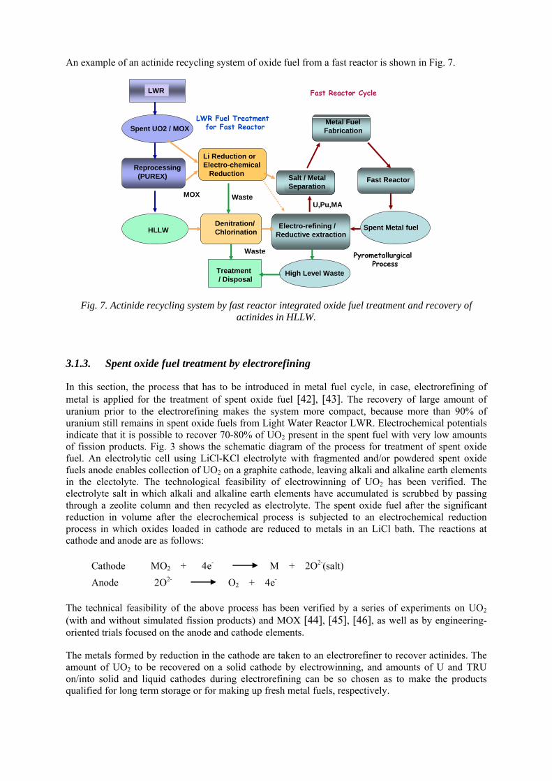
An example of an actinide recycling system of oxide fuel from a fast reactor is shown in Fig. 7.
Salt / MetalSeparation
Li Reduction orElectro-chemical
Reduction
High Level Waste
Spent UO2 / MOX
Reprocessing(PUREX)
HLLW Spent Metal fuelDenitration/Chlorination
Electro-refining /Reductive extraction
Metal FuelFabrication
Fast Reactor
MOX
LWR Fuel Treatmentfor Fast Reactor
LWR
PyrometallurgicalProcess
Fast Reactor Cycle
Treatment / Disposal
Waste
U,Pu,MAWaste
Fig. 7. Actinide recycling system by fast reactor integrated oxide fuel treatment and recovery of actinides in HLLW.
3.1.3. Spent oxide fuel treatment by electrorefining
In this section, the process that has to be introduced in metal fuel cycle, in case, electrorefining of metal is applied for the treatment of spent oxide fuel [42], [43]. The recovery of large amount of uranium prior to the electrorefining makes the system more compact, because more than 90% of uranium still remains in spent oxide fuels from Light Water Reactor LWR. Electrochemical potentials indicate that it is possible to recover 70-80% of UO2 present in the spent fuel with very low amounts of fission products. Fig. 3 shows the schematic diagram of the process for treatment of spent oxide fuel. An electrolytic cell using LiCl-KCl electrolyte with fragmented and/or powdered spent oxide fuels anode enables collection of UO2 on a graphite cathode, leaving alkali and alkaline earth elements in the electolyte. The technological feasibility of electrowinning of UO2 has been verified. The electrolyte salt in which alkali and alkaline earth elements have accumulated is scrubbed by passing through a zeolite column and then recycled as electrolyte. The spent oxide fuel after the significant reduction in volume after the elecrochemical process is subjected to an electrochemical reduction process in which oxides loaded in cathode are reduced to metals in an LiCl bath. The reactions at cathode and anode are as follows:
Cathode MO2 + 4e- M + 2O2-(salt)
Anode 2O2- O2 + 4e-
The technical feasibility of the above process has been verified by a series of experiments on UO2 (with and without simulated fission products) and MOX [44], [45], [46], as well as by engineering-oriented trials focused on the anode and cathode elements.
The metals formed by reduction in the cathode are taken to an electrorefiner to recover actinides. The amount of UO2 to be recovered on a solid cathode by electrowinning, and amounts of U and TRU on/into solid and liquid cathodes during electrorefining can be so chosen as to make the products qualified for long term storage or for making up fresh metal fuels, respectively.
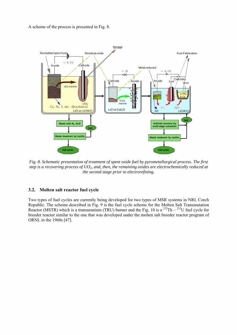
A scheme of the process is presented in Fig. 8.
Waste treatment by zeolite
FPU3+, TRUn+
~ 0.5V
Cs, Sr, I, etc. dissolution
Anode~ 0.5V
UO2
~ 3V
LiCl or LiCl/KCl
Decladded spent fuel
Cathode
Residual oxide
UO2 transfer
Storage
LiCl or CaCl2
O-ion transfer
Cathode Anode
Metal reduced
Anode SolidCathode
liquid
U,TRUIn CdU
LiCl/KCl
Fuel Fabrication
Waste with AL, ALE
Salt waste
Salt
Actinide recovery by multi-stage extraction
Salt
Salt waste
Waste treatment by zeolite
Fig. 8. Schematic presentation of treatment of spent oxide fuel by pyrometallurgical process. The first step is a recovering process of UO2, and, then, the remaining oxides are electrochemically reduced at
the second stage prior to electrorefining.
3.2. Molten salt reactor fuel cycle
Two types of fuel cycles are currently being developed for two types of MSR systems in NRI, Czech Republic. The scheme described in Fig. 9 is the fuel cycle scheme for the Molten Salt Transmutation Reactor (MSTR) which is a transuranium (TRU) burner and the Fig. 10 is a 232Th – 233U fuel cycle for breeder reactor similar to the one that was developed under the molten salt breeder reactor program of ORNL in the 1960s [47].
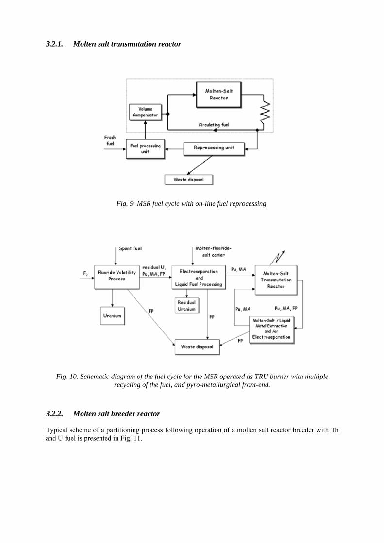
3.2.1. Molten salt transmutation reactor
Fig. 9. MSR fuel cycle with on-line fuel reprocessing.
Fig. 10. Schematic diagram of the fuel cycle for the MSR operated as TRU burner with multiple recycling of the fuel, and pyro-metallurgical front-end.
3.2.2. Molten salt breeder reactor
Typical scheme of a partitioning process following operation of a molten salt reactor breeder with Th and U fuel is presented in Fig. 11.
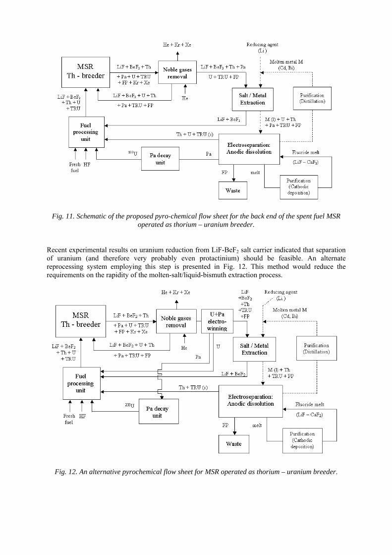
Fig. 11. Schematic of the proposed pyro-chemical flow sheet for the back end of the spent fuel MSR operated as thorium – uranium breeder.
Recent experimental results on uranium reduction from LiF-BeF2 salt carrier indicated that separation of uranium (and therefore very probably even protactinium) should be feasible. An alternate reprocessing system employing this step is presented in Fig. 12. This method would reduce the requirements on the rapidity of the molten-salt/liquid-bismuth extraction process.
Fig. 12. An alternative pyrochemical flow sheet for MSR operated as thorium – uranium breeder.
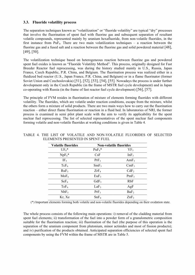
3.3. Fluoride volatility process
The separation techniques known as “volatilization” or “fluoride volatility” are typical “dry” processes that involve the fluorination of spent fuel with fluorine gas and subsequent separation of resultant volatile compounds, represented mainly by uranium hexafluoride, from non-volatile fluorides, in the first instance from PuF4. There are two main volatilization techniques – a reaction between the fluorine gas and a fused salt and a reaction between the fluorine gas and solid powdered material [48], [49], [50].
The volatilization technique based on heterogeneous reaction between fluorine gas and powdered spent fuel oxides is known as “Fluoride Volatility Method”. This process, originally designed for Fast Breeder Reactor fuel reprocessing, was during the history studied mainly in U.S., Russia, Japan France, Czech Republic, P.R. China, and Belgium. The fluorination process was realized either in a fluidized bed reactor (U.S., Japan France, P.R. China, and Belgium) or in a flame fluorinator (former Soviet Union and Czechoslovakia) [51], [52], [53], [54], [55]. Nowadays the process is under further development only in the Czech Republic (in the frame of MSTR fuel cycle development) and in Japan co-operating with Russia (in the frame of fast reactor fuel cycle development) [56], [57].
The principle of FVM resides in fluorination of mixture of elements forming fluorides with different volatility. The fluorides, which are volatile under reaction conditions, escape from the mixture, whilst the others form a mixture of solid products. There are two main ways how to carry out the fluorination reaction – either direct flame fluorination or reaction in a fluid bed. In laboratories of NRI, the former process is examined in semi pilot plant scale with the aim to verify its applicability for the spent nuclear fuel reprocessing. The list of selected representatives of the spent nuclear fuel components forming volatile and non-volatile fluorides at working conditions is given in Table 4. TABLE 4. THE LIST OF VOLATILE AND NON-VOLATILE FLUORIDES OF SELECTED ELEMENTS PRESENTED IN SPENT FUEL
Volatile fluorides Non-volatile fluorides UF6* PuF4* YF3
NpF6* CsF InF3
IF5 PrF3 AmF3
TcF6 SmF3 CmF3
RuF5 ZrF4 CdF2
MoF6 EuF3 PmF3
SeF6 GdF3 RbF
TeF6 LaF3 AgF
NbF5 PrF3 BaF2
Kr, Xe SnF4 ZnF2
(*) Important elements forming both volatile and non-volatile fluorides depending on their oxidation state.
The whole process consists of the following main operations: i) removal of the cladding material from spent fuel elements; ii) transformation of the fuel into a powder form of a granulometric composition suitable for the fluorination reaction; iii) fluorination of the fuel (the purpose of this operation is the separation of the uranium component from plutonium, minor actinides and most of fission products); and iv) purification of the products obtained. Anticipated separation efficiencies of selected spent fuel components by using the FVM within the frame of MSTR are in Table 5.
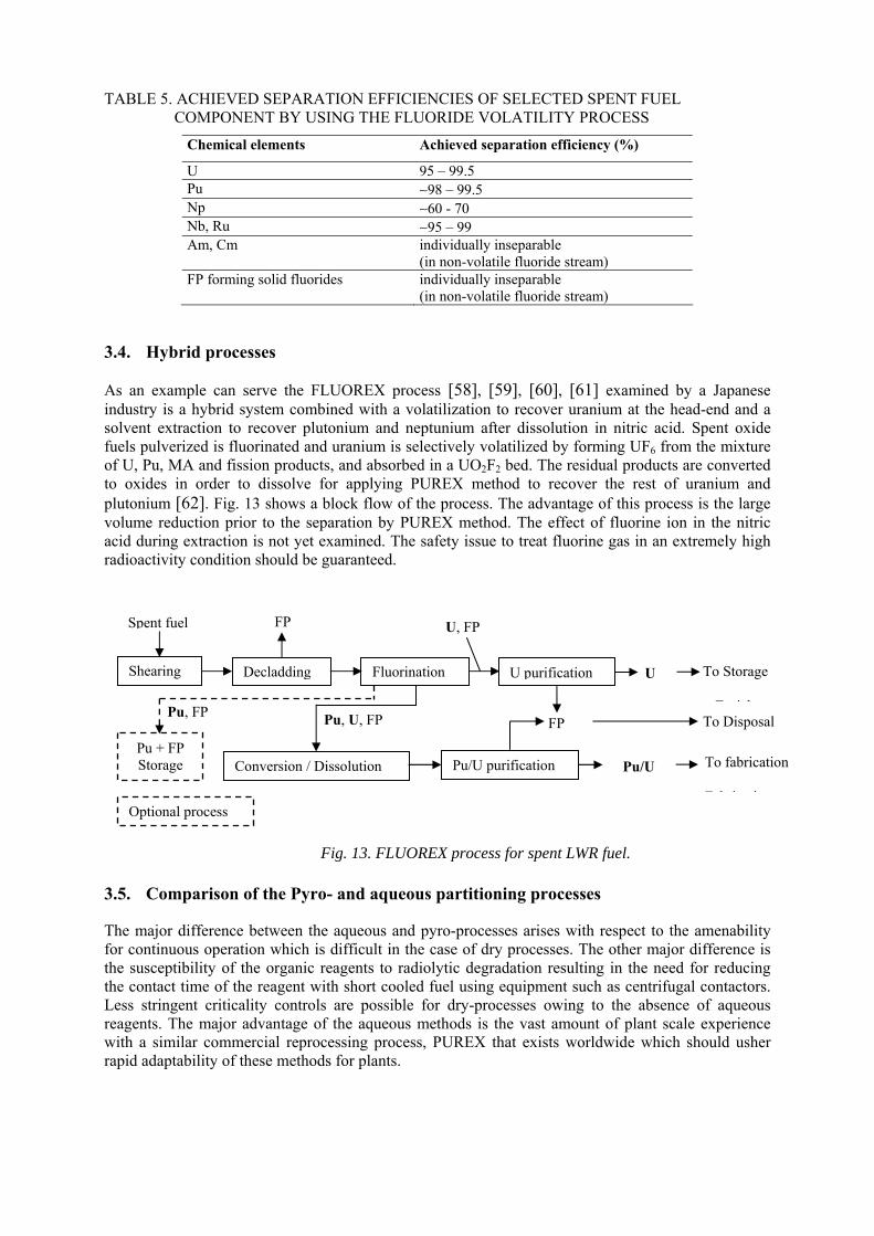
TABLE 5. ACHIEVED SEPARATION EFFICIENCIES OF SELECTED SPENT FUEL COMPONENT BY USING THE FLUORIDE VOLATILITY PROCESS
Chemical elements Achieved separation efficiency (%)
U 95 – 99.5 Pu ∼98 – 99.5 Np ∼60 - 70 Nb, Ru ∼95 – 99 Am, Cm individually inseparable
(in non-volatile fluoride stream) FP forming solid fluorides individually inseparable
(in non-volatile fluoride stream)
3.4. Hybrid processes
As an example can serve the FLUOREX process [58], [59], [60], [61] examined by a Japanese industry is a hybrid system combined with a volatilization to recover uranium at the head-end and a solvent extraction to recover plutonium and neptunium after dissolution in nitric acid. Spent oxide fuels pulverized is fluorinated and uranium is selectively volatilized by forming UF6 from the mixture of U, Pu, MA and fission products, and absorbed in a UO2F2 bed. The residual products are converted to oxides in order to dissolve for applying PUREX method to recover the rest of uranium and plutonium [62]. Fig. 13 shows a block flow of the process. The advantage of this process is the large volume reduction prior to the separation by PUREX method. The effect of fluorine ion in the nitric acid during extraction is not yet examined. The safety issue to treat fluorine gas in an extremely high radioactivity condition should be guaranteed.
3.5. Comparison of the Pyro- and aqueous partitioning processes
The major difference between the aqueous and pyro-processes arises with respect to the amenability for continuous operation which is difficult in the case of dry processes. The other major difference is the susceptibility of the organic reagents to radiolytic degradation resulting in the need for reducing the contact time of the reagent with short cooled fuel using equipment such as centrifugal contactors. Less stringent criticality controls are possible for dry-processes owing to the absence of aqueous reagents. The major advantage of the aqueous methods is the vast amount of plant scale experience with a similar commercial reprocessing process, PUREX that exists worldwide which should usher rapid adaptability of these methods for plants.
Fig. 13. FLUOREX process for spent LWR fuel.
Shearing Decladding Fluorination U purification
Spent fuel
Conversion / Dissolution Pu/U purification
U
Pu/U
FP
Pu + FP Storage
Pu, U, FP
U, FP
To Storage
E i h
Optional process
To fabrication
F b i i
To Disposal Pu, FP
FP
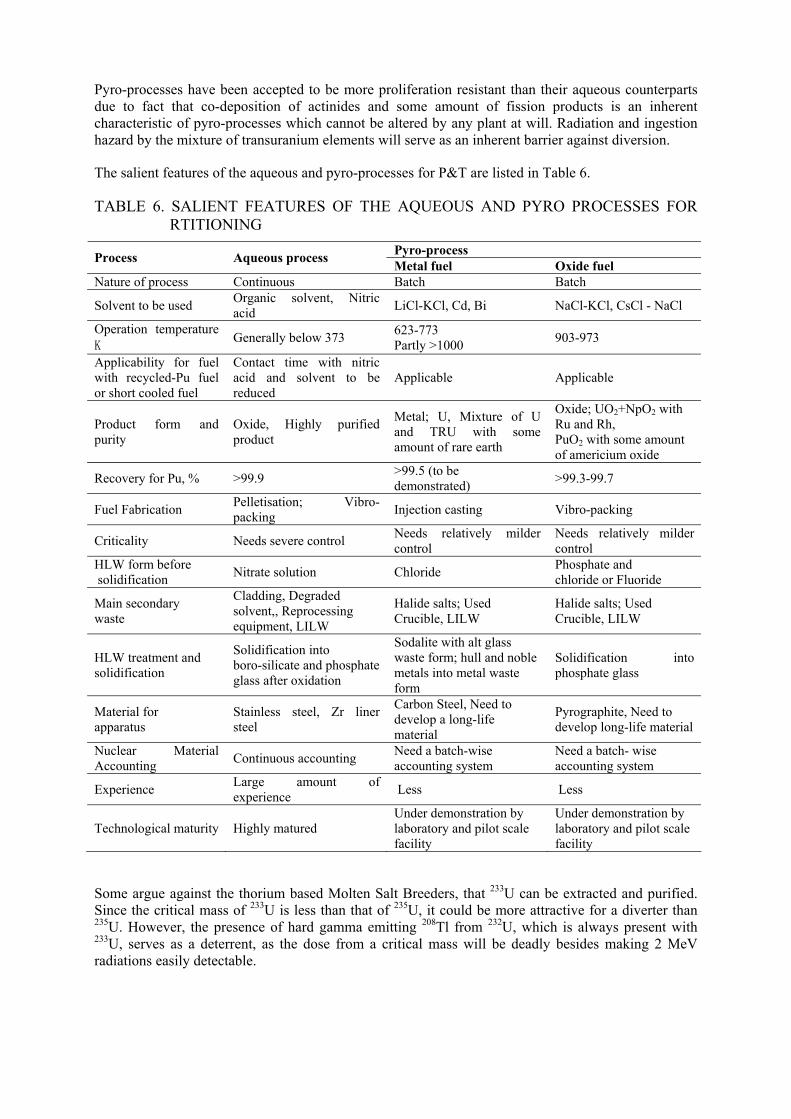
Pyro-processes have been accepted to be more proliferation resistant than their aqueous counterparts due to fact that co-deposition of actinides and some amount of fission products is an inherent characteristic of pyro-processes which cannot be altered by any plant at will. Radiation and ingestion hazard by the mixture of transuranium elements will serve as an inherent barrier against diversion.
The salient features of the aqueous and pyro-processes for P&T are listed in Table 6.
TABLE 6. SALIENT FEATURES OF THE AQUEOUS AND PYRO PROCESSES FOR RTITIONING
Pyro-process Process Aqueous process
Metal fuel Oxide fuel Nature of process Continuous Batch Batch
Solvent to be used Organic solvent, Nitric acid
LiCl-KCl, Cd, Bi NaCl-KCl, CsCl - NaCl
Operation temperature K
Generally below 373 623-773 Partly >1000
903-973
Applicability for fuel with recycled-Pu fuel or short cooled fuel
Contact time with nitric acid and solvent to be reduced
Applicable Applicable
Product form and purity
Oxide, Highly purified product
Metal; U, Mixture of U and TRU with some amount of rare earth
Oxide; UO2+NpO2 with Ru and Rh, PuO2 with some amount of americium oxide
Recovery for Pu, % >99.9 >99.5 (to be demonstrated)
>99.3-99.7
Fuel Fabrication Pelletisation; Vibro-packing
Injection casting Vibro-packing
Criticality Needs severe control Needs relatively milder control
Needs relatively milder control
HLW form before solidification
Nitrate solution Chloride Phosphate and chloride or Fluoride
Main secondary waste
Cladding, Degraded solvent,, Reprocessing equipment, LILW
Halide salts; Used Crucible, LILW
Halide salts; Used Crucible, LILW
HLW treatment and solidification
Solidification into boro-silicate and phosphate glass after oxidation
Sodalite with alt glass waste form; hull and noble metals into metal waste form
Solidification into phosphate glass
Material for apparatus
Stainless steel, Zr liner steel
Carbon Steel, Need to develop a long-life material
Pyrographite, Need to develop long-life material
Nuclear Material Accounting
Continuous accounting Need a batch-wise accounting system
Need a batch- wise accounting system
Experience Large amount of experience
Less Less
Technological maturity Highly matured Under demonstration by laboratory and pilot scale facility
Under demonstration by laboratory and pilot scale facility
Some argue against the thorium based Molten Salt Breeders, that 233U can be extracted and purified. Since the critical mass of 233U is less than that of 235U, it could be more attractive for a diverter than 235U. However, the presence of hard gamma emitting 208Tl from 232U, which is always present with 233U, serves as a deterrent, as the dose from a critical mass will be deadly besides making 2 MeV radiations easily detectable.
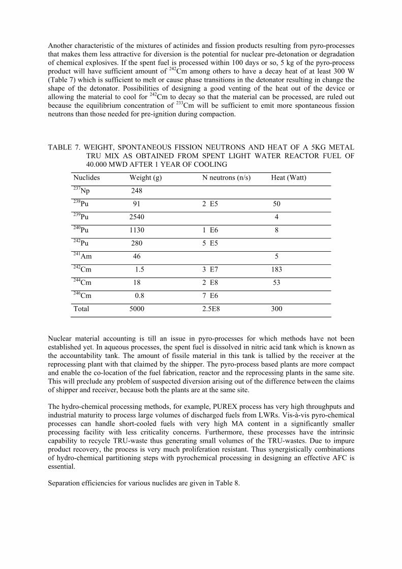
Another characteristic of the mixtures of actinides and fission products resulting from pyro-processes that makes them less attractive for diversion is the potential for nuclear pre-detonation or degradation of chemical explosives. If the spent fuel is processed within 100 days or so, 5 kg of the pyro-process product will have sufficient amount of 242Cm among others to have a decay heat of at least 300 W (Table 7) which is sufficient to melt or cause phase transitions in the detonator resulting in change the shape of the detonator. Possibilities of designing a good venting of the heat out of the device or allowing the material to cool for 242Cm to decay so that the material can be processed, are ruled out because the equilibrium concentration of 233Cm will be sufficient to emit more spontaneous fission neutrons than those needed for pre-ignition during compaction.
TABLE 7. WEIGHT, SPONTANEOUS FISSION NEUTRONS AND HEAT OF A 5KG METAL TRU MIX AS OBTAINED FROM SPENT LIGHT WATER REACTOR FUEL OF 40.000 MWD AFTER 1 YEAR OF COOLING
Nuclides Weight (g) N neutrons (n/s) Heat (Watt) 237Np 248 238Pu 91 2 E5 50 239Pu 2540 4 240Pu 1130 1 E6 8 242Pu 280 5 E5 241Am 46 5 242Cm 1.5 3 E7 183 244Cm 18 2 E8 53 246Cm 0.8 7 E6
Total 5000 2.5E8 300
Nuclear material accounting is till an issue in pyro-processes for which methods have not been established yet. In aqueous processes, the spent fuel is dissolved in nitric acid tank which is known as the accountability tank. The amount of fissile material in this tank is tallied by the receiver at the reprocessing plant with that claimed by the shipper. The pyro-process based plants are more compact and enable the co-location of the fuel fabrication, reactor and the reprocessing plants in the same site. This will preclude any problem of suspected diversion arising out of the difference between the claims of shipper and receiver, because both the plants are at the same site.
The hydro-chemical processing methods, for example, PUREX process has very high throughputs and industrial maturity to process large volumes of discharged fuels from LWRs. Vis-à-vis pyro-chemical processes can handle short-cooled fuels with very high MA content in a significantly smaller processing facility with less criticality concerns. Furthermore, these processes have the intrinsic capability to recycle TRU-waste thus generating small volumes of the TRU-wastes. Due to impure product recovery, the process is very much proliferation resistant. Thus synergistically combinations of hydro-chemical partitioning steps with pyrochemical processing in designing an effective AFC is essential.
Separation efficiencies for various nuclides are given in Table 8.
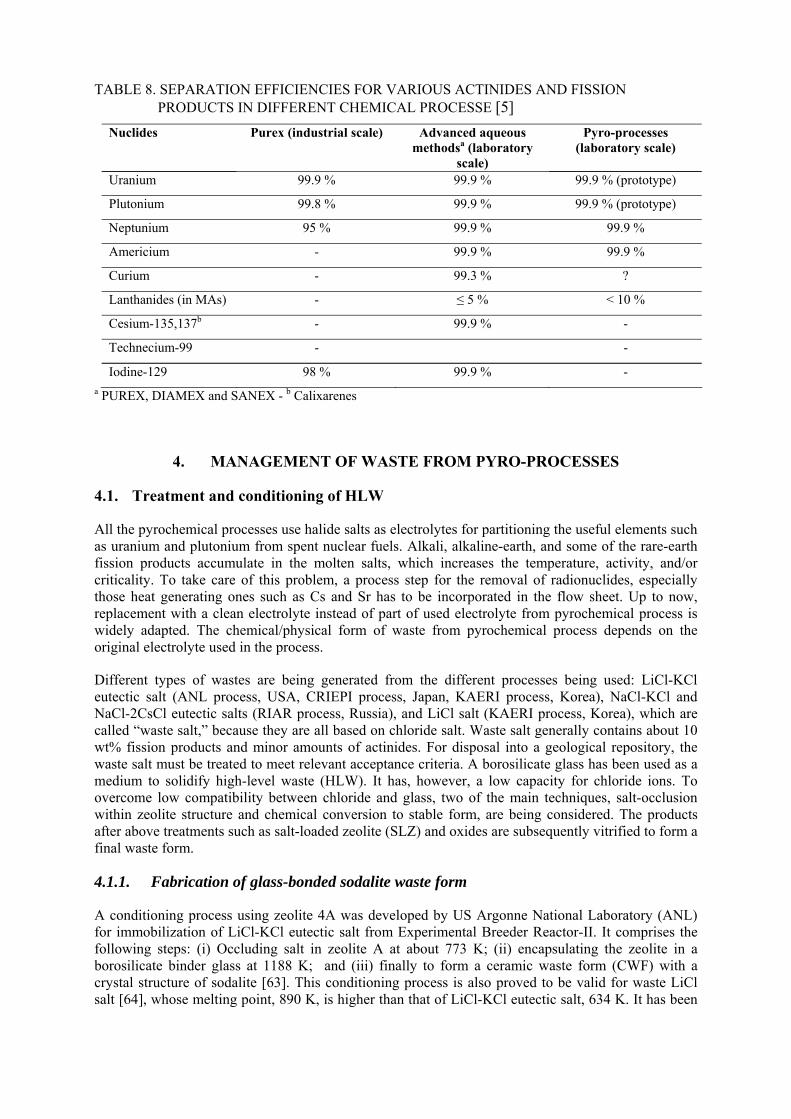
TABLE 8. SEPARATION EFFICIENCIES FOR VARIOUS ACTINIDES AND FISSION PRODUCTS IN DIFFERENT CHEMICAL PROCESSE [5]
Nuclides Purex (industrial scale) Advanced aqueous methodsa (laboratory
scale)
Pyro-processes (laboratory scale)
Uranium 99.9 % 99.9 % 99.9 % (prototype)
Plutonium 99.8 % 99.9 % 99.9 % (prototype)
Neptunium 95 % 99.9 % 99.9 %
Americium - 99.9 % 99.9 %
Curium - 99.3 % ?
Lanthanides (in MAs) - ≤ 5 % < 10 %
Cesium-135,137b - 99.9 % -
Technecium-99 - -
Iodine-129 98 % 99.9 % - a PUREX, DIAMEX and SANEX - b Calixarenes
4. MANAGEMENT OF WASTE FROM PYRO-PROCESSES
4.1. Treatment and conditioning of HLW
All the pyrochemical processes use halide salts as electrolytes for partitioning the useful elements such as uranium and plutonium from spent nuclear fuels. Alkali, alkaline-earth, and some of the rare-earth fission products accumulate in the molten salts, which increases the temperature, activity, and/or criticality. To take care of this problem, a process step for the removal of radionuclides, especially those heat generating ones such as Cs and Sr has to be incorporated in the flow sheet. Up to now, replacement with a clean electrolyte instead of part of used electrolyte from pyrochemical process is widely adapted. The chemical/physical form of waste from pyrochemical process depends on the original electrolyte used in the process.
Different types of wastes are being generated from the different processes being used: LiCl-KCl eutectic salt (ANL process, USA, CRIEPI process, Japan, KAERI process, Korea), NaCl-KCl and NaCl-2CsCl eutectic salts (RIAR process, Russia), and LiCl salt (KAERI process, Korea), which are called “waste salt,” because they are all based on chloride salt. Waste salt generally contains about 10 wt% fission products and minor amounts of actinides. For disposal into a geological repository, the waste salt must be treated to meet relevant acceptance criteria. A borosilicate glass has been used as a medium to solidify high-level waste (HLW). It has, however, a low capacity for chloride ions. To overcome low compatibility between chloride and glass, two of the main techniques, salt-occlusion within zeolite structure and chemical conversion to stable form, are being considered. The products after above treatments such as salt-loaded zeolite (SLZ) and oxides are subsequently vitrified to form a final waste form.
4.1.1. Fabrication of glass-bonded sodalite waste form
A conditioning process using zeolite 4A was developed by US Argonne National Laboratory (ANL) for immobilization of LiCl-KCl eutectic salt from Experimental Breeder Reactor-II. It comprises the following steps: (i) Occluding salt in zeolite A at about 773 K; (ii) encapsulating the zeolite in a borosilicate binder glass at 1188 K; and (iii) finally to form a ceramic waste form (CWF) with a crystal structure of sodalite [63]. This conditioning process is also proved to be valid for waste LiCl salt [64], whose melting point, 890 K, is higher than that of LiCl-KCl eutectic salt, 634 K. It has been
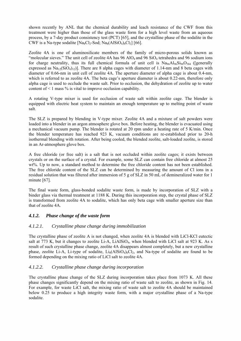
shown recently by ANL that the chemical durability and leach resistance of the CWF from this treatment were higher than those of the glass waste form for a high level waste from an aqueous process, by a 7-day product consistency test (PCT) [65], and the crystalline phase of the sodalite in the CWF is a Na-type sodalite [Na8Cl2-Sod; Na8(AlSiO4)6Cl2] [66].
Zeolite 4A is one of aluminosilicate members of the family of micro-porous solids known as “molecular sieves.” The unit cell of zeolite 4A has 96 AlO4 and 96 SiO4 tetrahedra and 96 sodium ions for charge neutrality, thus its full chemical formula of unit cell is Na96Al96Si96O384 ([generally expressed as Na12(SiO4)12)]. There are 8 alpha cages with diameter of 1.14-nm and 8 beta cages with diameter of 0.66-nm in unit cell of zeolite 4A. The aperture diameter of alpha cage is about 0.4-nm, which is referred to as zeolite 4A. The beta cage’s aperture diameter is about 0.22-nm, therefore only alpha cage is used to occlude the waste salt. Prior to occlusion, the dehydration of zeolite up to water content of < 1 mass % is vital to improve occlusion capability.
A rotating V-type mixer is used for occlusion of waste salt within zeolite cage. The blender is equipped with electric heat system to maintain an enough temperature up to melting point of waste salt.
The SLZ is prepared by blending in V-type mixer. Zeolite 4A and a mixture of salt powders were loaded into a blender in an argon atmosphere glove box. Before heating, the blender is evacuated using a mechanical vacuum pump. The blender is rotated at 20 rpm under a heating rate of 5 K/min. Once the blender temperature has reached 923 K, vacuum conditions are re-established prior to 20-h isothermal blending with rotation. After being cooled, the blended zeolite, salt-loaded zeolite, is stored in an Ar-atmosphere glove box.
A free chloride (or free salt) is a salt that is not occluded within zeolite cages; it exists between crystals or on the surface of a crystal. For example, some SLZ can contain free chloride at almost 25 wt%. Up to now, a standard method to determine the free chloride content has not been established. The free chloride content of the SLZ can be determined by measuring the amount of Cl ions in a residual solution that was filtered after immersion of 5 g of SLZ in 50 mL of demineralized water for 1 minute [67].
The final waste form, glass-bonded sodalite waste form, is made by incorporation of SLZ with a binder glass via thermal treatment at 1188 K. During this incorporation step, the crystal phase of SLZ is transformed from zeolite 4A to sodalite, which has only beta cage with smaller aperture size than that of zeolite 4A.
4.1.2. Phase change of the waste form
4.1.2.1. Crystalline phase change during immobilization
The crystalline phase of zeolite A is not changed, when zeolite 4A is blended with LiCl-KCl eutectic salt at 773 K, but it changes to zeolite Li-A, LiAlSiO4, when blended with LiCl salt at 923 K. As s result of such crystalline phase change, zeolite 4A disappears almost completely, but a new crystalline phase, zeolite Li-A, Li-type of sodalite, Li8(AlSiO4)6Cl2, and Na-type of sodalite are found to be formed depending on the mixing ratio of LiCl salt to zeolite 4A.
4.1.2.2. Crystalline phase change during incorporation
The crystalline phase change of the SLZ during incorporation takes place from 1073 K. All these phase changes significantly depend on the mixing ratio of waste salt to zeolite, as shown in Fig. 14. For example, for waste LiCl salt, the mixing ratio of waste salt to zeolite 4A should be maintained below 0.25 to produce a high integrity waste form, with a major crystalline phase of a Na-type sodalite.
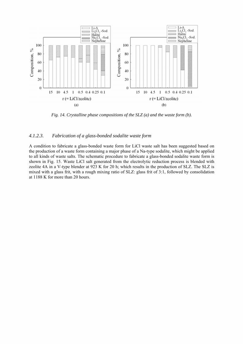
Fig. 14. Crystalline phase compositions of the SLZ (a) and the waste form (b).
4.1.2.3. Fabrication of a glass-bonded sodalite waste form
A condition to fabricate a glass-bonded waste form for LiCl waste salt has been suggested based on the production of a waste form containing a major phase of a Na-type sodalite, which might be applied to all kinds of waste salts. The schematic procedure to fabricate a glass-bonded sodalite waste form is shown in Fig. 15. Waste LiCl salt generated from the electrolytic reduction process is blended with zeolite 4A in a V-type blender at 923 K for 20 h; which results in the production of SLZ. The SLZ is mixed with a glass frit, with a rough mixing ratio of SLZ: glass frit of 3:1, followed by consolidation at 1188 K for more than 20 hours.
Fig. 15. Proposed procedure for the fabrication of a glass-bonded sodalite waste form.
4.1.3. Waste form characterization
The waste form for waste salts from pyrochemical processes needs some additional assessments and characterization for waste form integrity in a view of long term disposal. Some constraints and options relating to a waste conditioning process for P&T system are also considered. For example, new HLW form should be characterized with respect to the features given in the technical information in the USA [68]:
• The chemical composition and phase composition for HLW form; • Estimates of the total facility inventory and individual canister inventory of radionuclides; • The Time-Temperature-Transformation (TTT) diagrams for the HLW and identification of
temperature limit (if any) necessary to preserve the properties of the HLW form; and • Identification of the method to be used to assure consistency of production batches. 4.1.4. Metallic waste form in pyrochemical reprocessing
The metallic waste form developed by ANL, USA, is meant for the stainless steel cladding hulls, Zr from the alloy fuel, noble metal fission products and the small amounts of actinides left behind in the anode basket of the electrorefiner [69], [70], [71], [72], [73]. During the fabrication of the metallic waste form, at first, the salts sticking to the contents of the anode basket are removed by vacuum distillation at 1273K. Then, extra Zr is added, and the mixture melted at 1873 K in argon in a casting furnace, so as to form ingots of a durable stainless steel composition containing Zr to the extent of 15 wt. %. This constitutes the metal waste form, considered fit for disposal in geological repositories.
The microstructure of the SS-15Zr alloy consists of an iron-rich solid solution (ferritic phase) and an inter-metallic phase Zr(Fe,Cr,Ni)2+x. The actinides are found primarily in the inter-metallic phase, and hence retained well within the matrix (no separate actinide-rich phase is formed). The host phases for actinides in simulated waste forms have been reported in detail [73]. The noble metals are distributed between the inter-metallic phase and the iron solid solution; no discrete noble metal phase is formed. Ingots of the waste form of 23.75 cm dia.in diameter and 10 – 15 cm of thickness, weighing 30 – 40 kg, have been prepared. Prolonged MCC-1 leach tests involving static immersion in deionized water at 363 K, and electrochemical linear polarization measurements have shown negligible corrosion of the waste form.
Based on demonstration work on 1 MT of spent metallic fuel, ANL has estimated that their programme of electro-metallurgical processing 25 MTHM (metric tones of heavy metal) in the period 2005-2017 will produce 5.85 MT of the metallic waste (3.8 m3 of disposal volume inclusive of package).
4.1.5. Advanced characterization methods
Isotopic and elemental characterization of materials bearing actinides is essential for determining the process losses of actinides, in view of their strategic importance and potential radiation hazard. It is also important for nuclear material accounting and fissile material tracking for criticality control, especially when fuel materials of different compositions are used or/ considered for various reactor applications. Analysis of higher actinides, though produced in relatively less quantities in reactors, is receiving greater attention in view of the growing interest for burning them in the reactors and thus minimising waste storage burdens. Waste disposal facilities require the data not only on minor actinides but also on long lived FPs to assess the environmental impacts. Thus, precise and accurate analysis of long-lived actinide isotopes is of increasing importance in nuclear and geo-chemical fields.
Thermal Ionization Mass Spectrometry (TIMS) is an established technique for providing reliable isotopic abundances as well as elemental concentrations for actinides. The technique requires the actinides in pure chemical form (as nitrate) in order to have good emission characteristics as well as to avoid isobaric interferences (M= 238U&Pu; M= 241Pu and Am; M= 244Am; and Cm). The isotope ratios 234/238, 235/238 and 236/238 for U and 240/239, 241/239 and 242/239 for Pu are measured for the computation of plutonium isotopic compositions. For Am, isotopes of M =241 and 243 are monitored and for Cm, isotopes of M= 243 to 247 are monitored as well [74]. For isotopic dilution mass spectrometric technique, enriched isotopes of 233U and 242Pu (244Pu) are used as spike materials and are added in known quantities to the unknown samples and the pertinent isotope ratios are measured to deduce the elemental concentration. Though isotopic abundances are measured by mass spectrometry, the quantification of the minor actinides is usually done by radiometry. For separation of actinides different separation schemes are reported. In one study, Ion-Chromatograph coupled with inductively coupled plasma mass spectrometry (ICP-MS) was used for the characterization of actinides in spent fuel and high level waste samples [75].
Non-destructive radiometric techniques such as energy-dispersive X ray fluorescence analysis (XRF), neutron coincidence counting (NCC) and high-resolution gamma spectrometry (HRGS) are used for interrogating passively the quantity of minor actinides such as Am and Cm in process samples. In one particular study, the results obtained from the above methods were compared with the one carried out using ICP-MS technique [76].
ICP-MS is emerging as powerful analytical technique to yield isotopic composition as well as concentrations with the capabilities of fast analysis, high throughput, high sensitivity and reasonable precision and accuracy. It is essentially a mass spectrometric technique which uses plasma source to produce ions. The energy spread imminent with such a source (temperature of the order of 10 000 K) renders resolution of the ion beam poor but the choice of proper mass analyzer provides solution to this problem [77]. For actinides, several laboratories around the world have started employing this technique incorporating on-line separation facilities, for environmental samples [78], so that pure
fractions are let into the inlet of the ion source of the mass spectrometer. Basic steps remaining the same, separation procedures can be fine tuned for nuclear materials containing actinides depending upon the nature of the sample.
Another area that necessitates development of advanced characterization methods is the determination of actinides and lanthanides, especially when one of them is present in low levels with the other being present in large amounts. High Performance Liquid Chromatography with suitable solvents and modifiers has been employed for such applications [79], [80] which is discussed in detail in the Annexure-I. In the recent years, electro-analytical techniques such as square wave voltammetry have been investigated for on-line analysis of actinides [81], [82]. Such online techniques would help to reduce the losses encountered by sampling, dilution etc. which normally involve dissolution in aqueous solutions.
To determine the plutonium and minor actinides traces in discharged pyro-process wastes, one can rely on the active and passive non-destructive techniques that have been used for PUREX process wastes [76], [83].
5. ESTIMATION OF PROCESS LOSSES IN PYRO-PROCESSES
5.1. General
One of the main requirements for industrial realization is to evaluate precisely the process losses and minimize them. In this chapter, process losses are evaluated based on the present knowledge of each technology.
The losses could be separated into two categories, namely, separation losses and process losses. The former losses ones are mainly attributed to the separation potential of the process that could be predicted precisely by using the theoretically derived distribution coefficients, separation factors and/or decontamination factors. The process losses are mainly caused by process-oriented factors, such as material adhering to claddings, etc. It depends on the decladding method used, effectiveness of rinsing after removing the fuel and the amount of residual material in vessels, etc. It is possible to reduce the losses by repeated rinsing or multistage operation, the number of rinsing cycles and stages being optimized from the economy point of view. Moreover, the virtual losses arise due to the inaccuracy in the measurement of actinide material and plating out of the components of a plant such as vessels, tanks and piping, which are assembled, depending on the plant design. Typical process losses originating from a partitioning process aimed at fabrication of actinide bearing fuel are presented in Fig. 16.
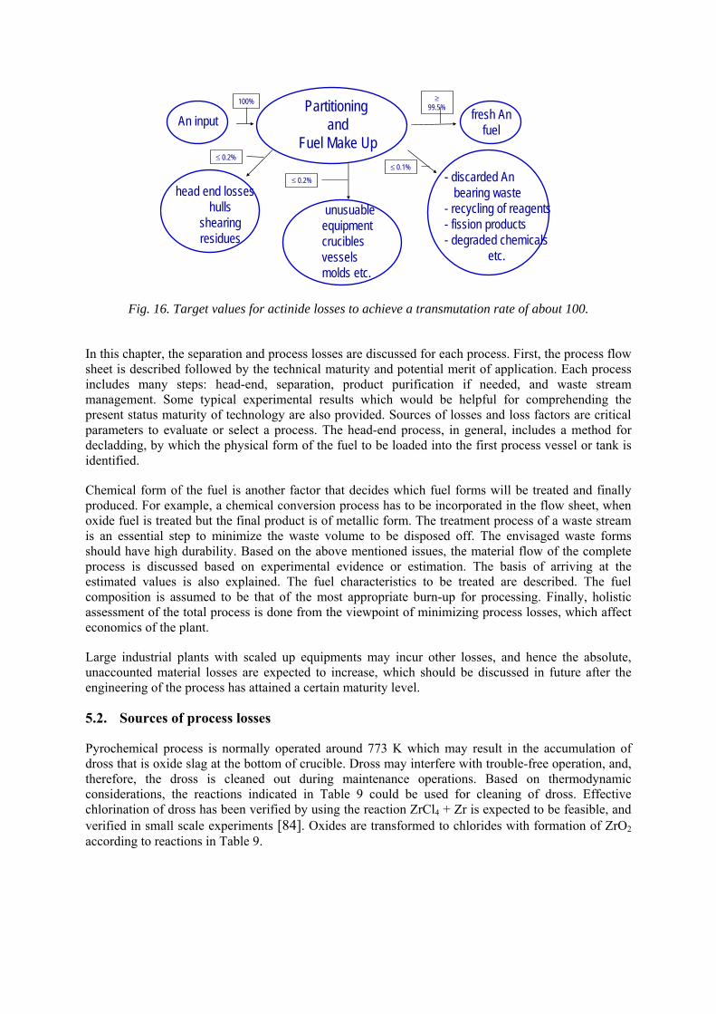
Partitioningand
Fuel Make UpAn input fresh An
fuel
head end losses hulls
shearingresidues
unusuable equipmentcruciblesvesselsmolds etc.
- discarded An bearing waste
- recycling of reagents- fission products- degraded chemicals
etc.
100% ≥99.5%
≤ 0.2%
≤ 0.2%≤ 0.1%
Fig. 16. Target values for actinide losses to achieve a transmutation rate of about 100.
In this chapter, the separation and process losses are discussed for each process. First, the process flow sheet is described followed by the technical maturity and potential merit of application. Each process includes many steps: head-end, separation, product purification if needed, and waste stream management. Some typical experimental results which would be helpful for comprehending the present status maturity of technology are also provided. Sources of losses and loss factors are critical parameters to evaluate or select a process. The head-end process, in general, includes a method for decladding, by which the physical form of the fuel to be loaded into the first process vessel or tank is identified.
Chemical form of the fuel is another factor that decides which fuel forms will be treated and finally produced. For example, a chemical conversion process has to be incorporated in the flow sheet, when oxide fuel is treated but the final product is of metallic form. The treatment process of a waste stream is an essential step to minimize the waste volume to be disposed off. The envisaged waste forms should have high durability. Based on the above mentioned issues, the material flow of the complete process is discussed based on experimental evidence or estimation. The basis of arriving at the estimated values is also explained. The fuel characteristics to be treated are described. The fuel composition is assumed to be that of the most appropriate burn-up for processing. Finally, holistic assessment of the total process is done from the viewpoint of minimizing process losses, which affect economics of the plant.
Large industrial plants with scaled up equipments may incur other losses, and hence the absolute, unaccounted material losses are expected to increase, which should be discussed in future after the engineering of the process has attained a certain maturity level.
5.2. Sources of process losses
Pyrochemical process is normally operated around 773 K which may result in the accumulation of dross that is oxide slag at the bottom of crucible. Dross may interfere with trouble-free operation, and, therefore, the dross is cleaned out during maintenance operations. Based on thermodynamic considerations, the reactions indicated in Table 9 could be used for cleaning of dross. Effective chlorination of dross has been verified by using the reaction ZrCl4 + Zr is expected to be feasible, and verified in small scale experiments [84]. Oxides are transformed to chlorides with formation of ZrO2 according to reactions in Table 9.
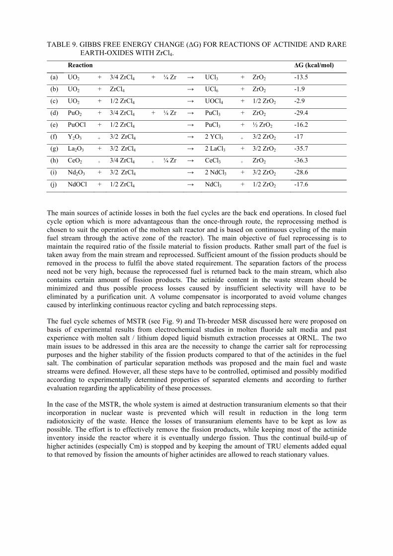
TABLE 9. GIBBS FREE ENERGY CHANGE (ΔG) FOR REACTIONS OF ACTINIDE AND RARE EARTH-OXIDES WITH ZrCl4.
Reaction ΔG (kcal/mol)
(a) UO2 + 3/4 ZrCl4 + ¼ Zr → UCl3 + ZrO2 -13.5
(b) UO2 + ZrCl4 → UCl6 + ZrO2 -1.9
(c) UO2 + 1/2 ZrCl4 → UOCl4 + 1/2 ZrO2 -2.9
(d) PuO2 + 3/4 ZrCl4 + ¼ Zr → PuCl3 + ZrO2 -29.4
(e) PuOCl + 1/2 ZrCl4 → PuCl3 + ½ ZrO2 -16.2
(f) Y2O3 + 3/2 ZrCl4 → 2 YCl3 + 3/2 ZrO2 -17
(g) La2O3 + 3/2 ZrCl4 → 2 LaCl3 + 3/2 ZrO2 -35.7
(h) CeO2 + 3/4 ZrCl4 + ¼ Zr → CeCl3 + ZrO2 -36.3
(i) Nd2O3 + 3/2 ZrCl4 → 2 NdCl3 + 3/2 ZrO2 -28.6
(j) NdOCl + 1/2 ZrCl4 → NdCl3 + 1/2 ZrO2 -17.6
The main sources of actinide losses in both the fuel cycles are the back end operations. In closed fuel cycle option which is more advantageous than the once-through route, the reprocessing method is chosen to suit the operation of the molten salt reactor and is based on continuous cycling of the main fuel stream through the active zone of the reactor). The main objective of fuel reprocessing is to maintain the required ratio of the fissile material to fission products. Rather small part of the fuel is taken away from the main stream and reprocessed. Sufficient amount of the fission products should be removed in the process to fulfil the above stated requirement. The separation factors of the process need not be very high, because the reprocessed fuel is returned back to the main stream, which also contains certain amount of fission products. The actinide content in the waste stream should be minimized and thus possible process losses caused by insufficient selectivity will have to be eliminated by a purification unit. A volume compensator is incorporated to avoid volume changes caused by interlinking continuous reactor cycling and batch reprocessing steps.
The fuel cycle schemes of MSTR (see Fig. 9) and Th-breeder MSR discussed here were proposed on basis of experimental results from electrochemical studies in molten fluoride salt media and past experience with molten salt / lithium doped liquid bismuth extraction processes at ORNL. The two main issues to be addressed in this area are the necessity to change the carrier salt for reprocessing purposes and the higher stability of the fission products compared to that of the actinides in the fuel salt. The combination of particular separation methods was proposed and the main fuel and waste streams were defined. However, all these steps have to be controlled, optimised and possibly modified according to experimentally determined properties of separated elements and according to further evaluation regarding the applicability of these processes.
In the case of the MSTR, the whole system is aimed at destruction transuranium elements so that their incorporation in nuclear waste is prevented which will result in reduction in the long term radiotoxicity of the waste. Hence the losses of transuranium elements have to be kept as low as possible. The effort is to effectively remove the fission products, while keeping most of the actinide inventory inside the reactor where it is eventually undergo fission. Thus the continual build-up of higher actinides (especially Cm) is stopped and by keeping the amount of TRU elements added equal to that removed by fission the amounts of higher actinides are allowed to reach stationary values.
5.3. Estimation of process losses
5.3.1. Process losses from PWRs and PWR-MSTR
The process losses from the fuel cycle of a contemporary pressurized water reactor (PWR) and a futuristic PWR-MSTR park (based on the principle in which TRUs produced by PWRs are being consumed by appropriate number of MSTRs) have been computed for comparison. The following assumptions were made for the computation:
(a) Actinide loss during reprocessing is limited to 0.1%; (b) The total amount of fuel salt in the reactor can be reprocessed in 150 days, and (c) The efficiency of FP removal is 50% [48]. Estimation of the process losses in the Molten Salt Reactor (MSR) [85] fuel cycle would be possible only when the technology for continuous reprocessing of the fuel salt is fully developed and since it is yet to be achieved, estimation is rendered difficult. In addition, it has to be mentioned that two waste streams have to be considered for the total estimate, the separated FPs and the contaminated salt, both in the form of HLW. However, it can be reasonable assumed, based on the basic principles of the technology which are well-understood, that the process losses can be reduced below the target values set for the specific MSR system.
5.3.2. Process losses from a Th-breeder MSR
The analysis of process losses of the Th-breeder MSR is somewhat more complex than that of MSTR. The primary requirements on the Th-breeder fuel cycle are to:
• ensure high breeding ratio by preventing neutron capture by 233Pa (decaying to 233U with half-life of 27 days); and
• prevent losses of the precious fissile material (233U and its precursor 233Pa) from the Th-breeder MSR fuel cycle.
The prevention of neutron capture by protactinium is achieved by rapid and continuous separation of this element from the fuel salt. With respect to the protactinium content, all the reactor salt should be processed at least once in three days (separation of fission products from the fuel salt can be performed more slowly in periods reaching several hundred days). The separation losses are a major point of interest here. The consequent requirement on protactinium losses to waste is that it should be lower than 0.01% of total Pa processed per year (losses of 233U produced by 233Pa decay will be probably kept at trace level as the separation step will be performed by a reliable step of fused salt fluorination) whereas the losses of other actinides could be up to 0.1% and the losses of thorium to waste could even be more than 1%, as thorium is cheap and abundant and its radiotoxicity is insignificant compared to the fission products in the waste. The key-technique of molten salt / liquid bismuth reductive extraction using lithium followed by some electrochemical separation steps is used in the separation scheme on Fig. 11. This technology suggested by us should remove certain deficiency of the original technology developed in ORNL. The former technology was based on molten salt/liquid metal extraction, which combined an extraction from fluoride salt FLIBE (Li2BeF4) with extraction from chloride salt (LiCl). It resulted in the introduction of F- ions into the LiCl system, which finally resulted in a loss of Th from the process.
5.3.3. Process losses from the electrowinning process
Among tasks solved at RIAR, Dimitrovgrad, Russia, accurate data have been obtained on the mass balance of U and Pu, and on U and Pu distribution in wastes and recycled products of the technology. Table 10 shows representative results of such experimental works. It indicates that approximately 98 % of U and Pu could be recovered as fuel. Approximately 0.54% of U and Pu were included in waste streams and considered not recoverable.
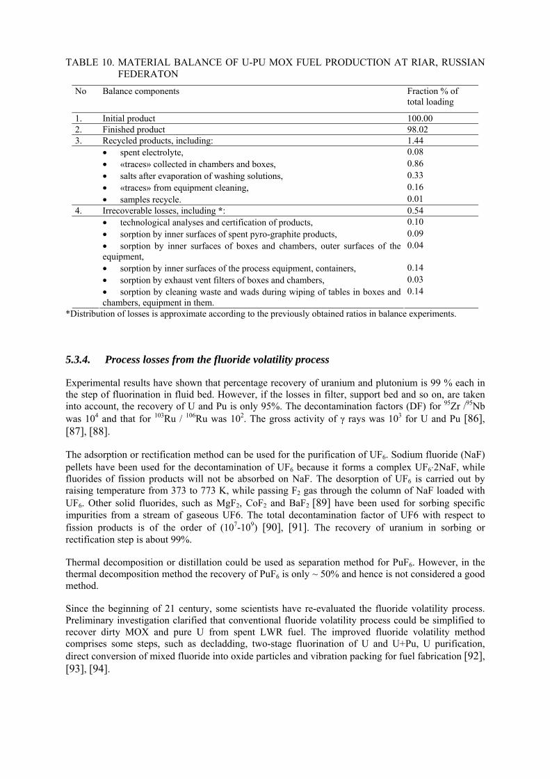
TABLE 10. MATERIAL BALANCE OF U-PU MOX FUEL PRODUCTION AT RIAR, RUSSIAN FEDERATON
No Balance components Fraction % of total loading
1. Initial product 100.00 2. Finished product 98.02 3. Recycled products, including: 1.44
• spent electrolyte, 0.08 • «traces» collected in chambers and boxes, 0.86 • salts after evaporation of washing solutions, 0.33 • «traces» from equipment cleaning, 0.16
• samples recycle. 0.01 4. Irrecoverable losses, including *: 0.54
• technological analyses and certification of products, 0.10 • sorption by inner surfaces of spent pyro-graphite products, 0.09 • sorption by inner surfaces of boxes and chambers, outer surfaces of the equipment,
0.04
• sorption by inner surfaces of the process equipment, containers, 0.14 • sorption by exhaust vent filters of boxes and chambers, 0.03
• sorption by cleaning waste and wads during wiping of tables in boxes and chambers, equipment in them.
0.14
*Distribution of losses is approximate according to the previously obtained ratios in balance experiments.
5.3.4. Process losses from the fluoride volatility process
Experimental results have shown that percentage recovery of uranium and plutonium is 99 % each in the step of fluorination in fluid bed. However, if the losses in filter, support bed and so on, are taken into account, the recovery of U and Pu is only 95%. The decontamination factors (DF) for 95Zr /95Nb was 104 and that for 103Ru / 106Ru was 102. The gross activity of γ rays was 103 for U and Pu [86], [87], [88].
The adsorption or rectification method can be used for the purification of UF6. Sodium fluoride (NaF) pellets have been used for the decontamination of UF6 because it forms a complex UF6⋅2NaF, while fluorides of fission products will not be absorbed on NaF. The desorption of UF6 is carried out by raising temperature from 373 to 773 K, while passing F2 gas through the column of NaF loaded with UF6. Other solid fluorides, such as MgF2, CoF2 and BaF2 [89] have been used for sorbing specific impurities from a stream of gaseous UF6. The total decontamination factor of UF6 with respect to fission products is of the order of (107-109) [90], [91]. The recovery of uranium in sorbing or rectification step is about 99%.
Thermal decomposition or distillation could be used as separation method for PuF6. However, in the thermal decomposition method the recovery of PuF6 is only ~ 50% and hence is not considered a good method.
Since the beginning of 21 century, some scientists have re-evaluated the fluoride volatility process. Preliminary investigation clarified that conventional fluoride volatility process could be simplified to recover dirty MOX and pure U from spent LWR fuel. The improved fluoride volatility method comprises some steps, such as decladding, two-stage fluorination of U and U+Pu, U purification, direct conversion of mixed fluoride into oxide particles and vibration packing for fuel fabrication [92], [93], [94].
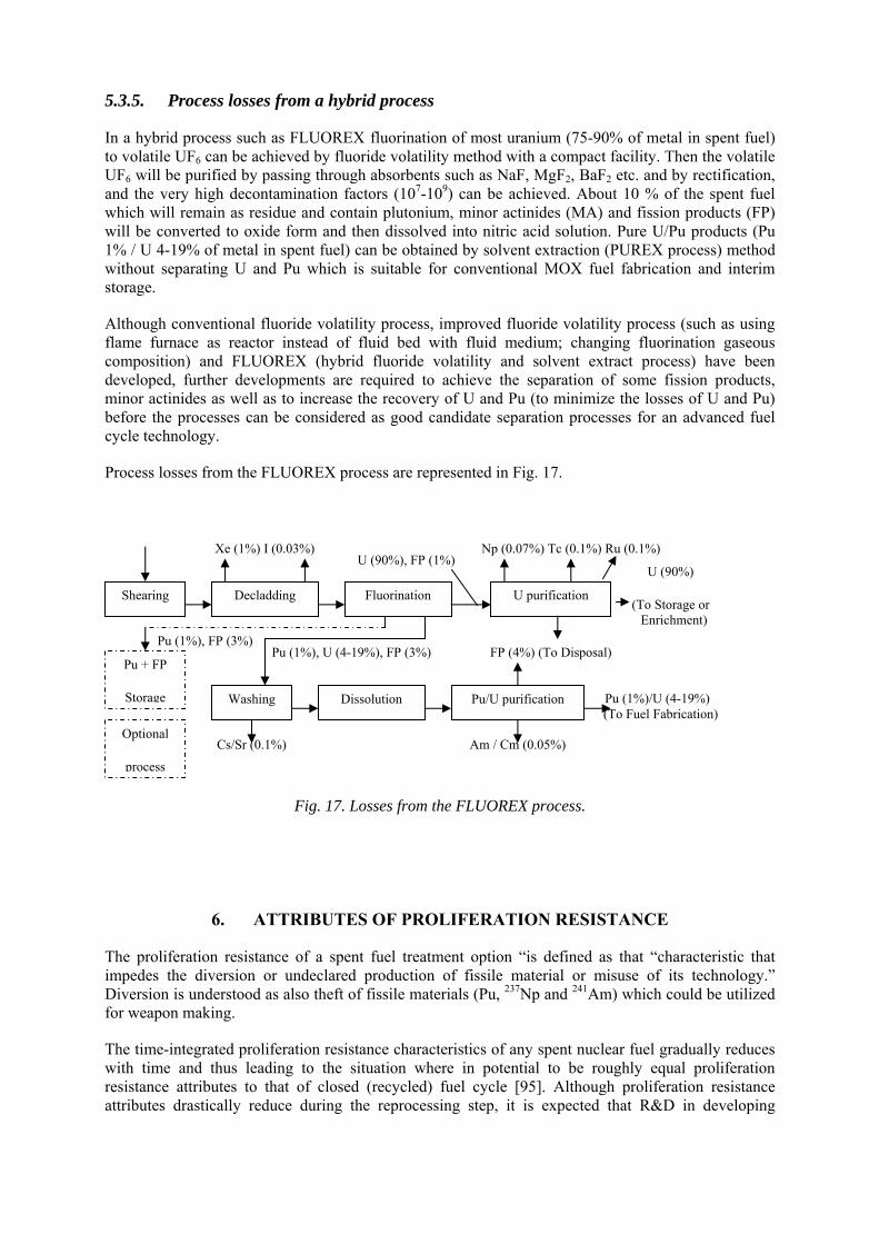
5.3.5. Process losses from a hybrid process
In a hybrid process such as FLUOREX fluorination of most uranium (75-90% of metal in spent fuel) to volatile UF6 can be achieved by fluoride volatility method with a compact facility. Then the volatile UF6 will be purified by passing through absorbents such as NaF, MgF2, BaF2 etc. and by rectification, and the very high decontamination factors (107-109) can be achieved. About 10 % of the spent fuel which will remain as residue and contain plutonium, minor actinides (MA) and fission products (FP) will be converted to oxide form and then dissolved into nitric acid solution. Pure U/Pu products (Pu 1% / U 4-19% of metal in spent fuel) can be obtained by solvent extraction (PUREX process) method without separating U and Pu which is suitable for conventional MOX fuel fabrication and interim storage.
Although conventional fluoride volatility process, improved fluoride volatility process (such as using flame furnace as reactor instead of fluid bed with fluid medium; changing fluorination gaseous composition) and FLUOREX (hybrid fluoride volatility and solvent extract process) have been developed, further developments are required to achieve the separation of some fission products, minor actinides as well as to increase the recovery of U and Pu (to minimize the losses of U and Pu) before the processes can be considered as good candidate separation processes for an advanced fuel cycle technology.
Process losses from the FLUOREX process are represented in Fig. 17.
Fig. 17. Losses from the FLUOREX process.
6. ATTRIBUTES OF PROLIFERATION RESISTANCE
The proliferation resistance of a spent fuel treatment option “is defined as that “characteristic that impedes the diversion or undeclared production of fissile material or misuse of its technology.” Diversion is understood as also theft of fissile materials (Pu, 237Np and 241Am) which could be utilized for weapon making.
The time-integrated proliferation resistance characteristics of any spent nuclear fuel gradually reduces with time and thus leading to the situation where in potential to be roughly equal proliferation resistance attributes to that of closed (recycled) fuel cycle [95]. Although proliferation resistance attributes drastically reduce during the reprocessing step, it is expected that R&D in developing
U purification
Cs/Sr (0.1%)
FP (4%) (To Disposal) Pu (1%), FP (3%)
Pu (1%), U (4-19%), FP (3%)
Fluorination Decladding Shearing
U (90%)
(To Storage or Enrichment)
Am / Cm (0.05%)
U (90%), FP (1%) Xe (1%) I (0.03%)
Pu + FP
Storage
Optional
process
Washing Pu/U purification Dissolution
Np (0.07%) Tc (0.1%) Ru (0.1%)
Pu (1%)/U (4-19%) (To Fuel Fabrication)
innovative closed fuel cycles with minor actinide co-recovery and recycle has the potential to enhance significantly proliferation resistance.
237Np is isotopically pure, due to the short half lives of the other neptunium isotopes. Nuclides like 237Np with an even number of neutrons exhibit a sharp threshold in their fission cross section, at around 500 keV. Below this energy threshold the fission cross section is quite low, making it relatively difficult to burn 237Np in reactors and explaining why it is not currently commonly recovered by reprocessing. However, above the threshold 237Np exhibits a similar fission cross section to 235U. The critical mass of 237Np has been measured experimentally as 56 kg, almost identical to that of highly enriched uranium. Combined with a spontaneous fission rate comparable to 235U, this leads to the conclusion that 237Np has, in principal, roughly the same utility for nuclear explosives as highly enriched uranium. Like 237Np, 241Am is even more compressible, which makes it attractive despite its bare critical mass of 59 Kg. 243Am is a strong gamma-emitter, which reduces its utility for nuclear explosives when compared to 237Np, 241Am and Pu. In the long term, due to its 7 370 year half-life, 243Am constitutes a 239Pu source e.g. in PUREX-HLW.
From non-proliferation aspects any fuel cycle option ought to be advocated, which from its design stage on should already meet world wide public concern of diversion of fissile material and its misuse (e.g. by terrorist groups). Therefore the development of advanced spent fuel reprocessing should aim at technologies with intrinsic barriers that - under normal operation - exclude the production of weapon useable fissile material at all stages of the process. In other words; the obtained products will be not different from the unprocessed spent fuel in regard to its direct use as nuclear explosives. Complementary institutional measures would have to verify the declared operation and detect any alteration of the licensed process for a clandestine production of weapon useable fissile material. Technical barriers must hamper a change of the licensed process to such an extent, that for proliferators the clandestine setting up of a separate PUREX type process could be much easier achieved. The detection of clandestine operations is subject to IAEA safeguards under the “additional protocol”. Hence for such a scenario the role of international safeguards by the IAEA would rather be to verify the absence of weapon useable fissile material than of verifying the existence of a declared mass of weapon useable fissile material.
According to IAEA TECDOC-1434 [96] proliferation resistance criteria should meet two basic principles, namely “proliferation features and measures shall be implemented throughout the full life for innovative nuclear energy systems …” and “both intrinsic features and extrinsic measures are essential, and neither shall be considered sufficient by itself.” However, it should be noted that intrinsic features are superior to extrinsic features. The latter are subject to malevolent human interventions. Therefore processes with a large intrinsic proliferation potential must be preferred.
6.1. Types of intrinsic proliferation barriers
Intrinsic proliferation resistance features of fissile materials:
• Isotopic abundance (thermal output, neutron generation etc); • Actinide composition (U/Pu ratio, MA content etc); • Degree of difficulty to separate out fissile material from final or intermediate products; • Ease to change or to adapt a technology from normal to abnormal operation to separate out
weapon useable fissile material; • Group separation of actinides; • Change of an existing plant must be more complex than building a clandestine facility; • The process has only intermediate or final products emitting a fatal radiation dose for significant
quantities; and • Integrated concepts (IFR) favouring ‘containment and surveillance’ (C&S) measures. Contrary to aqueous partitioning, the pyro-chemically separated actinides are not as much decontaminated from fission products. This does not seriously affect their use as fast reactor fuels but
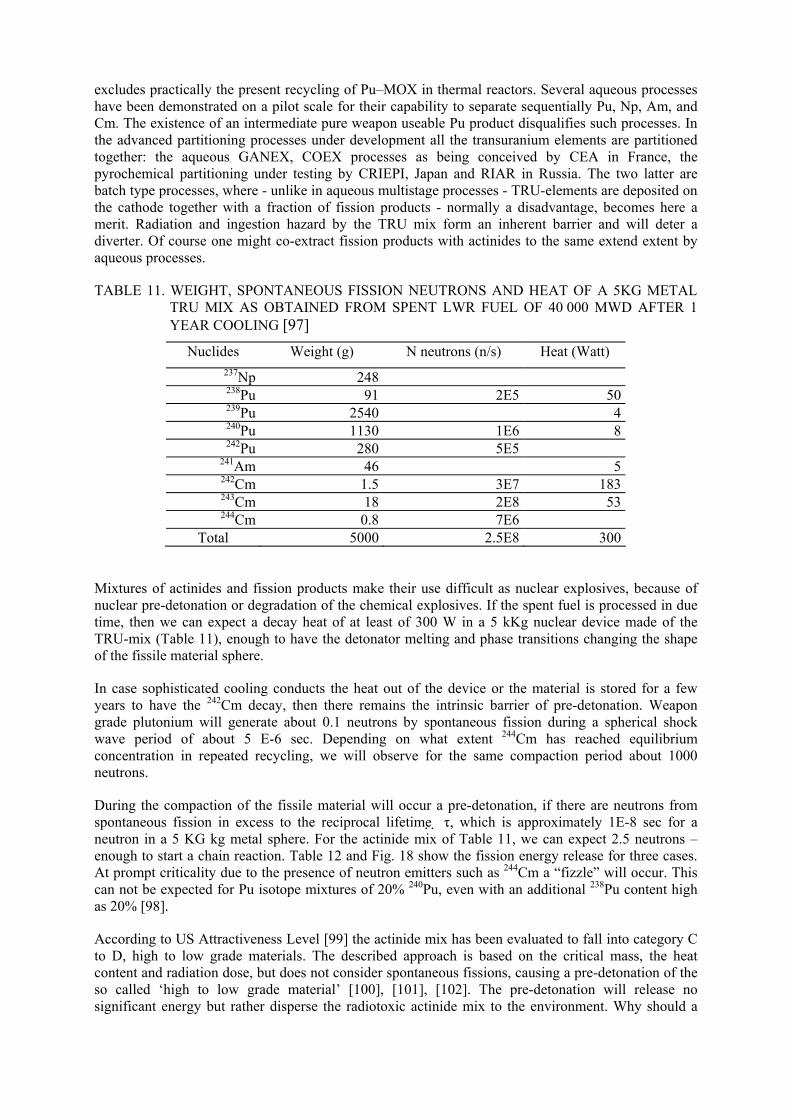
excludes practically the present recycling of Pu–MOX in thermal reactors. Several aqueous processes have been demonstrated on a pilot scale for their capability to separate sequentially Pu, Np, Am, and Cm. The existence of an intermediate pure weapon useable Pu product disqualifies such processes. In the advanced partitioning processes under development all the transuranium elements are partitioned together: the aqueous GANEX, COEX processes as being conceived by CEA in France, the pyrochemical partitioning under testing by CRIEPI, Japan and RIAR in Russia. The two latter are batch type processes, where - unlike in aqueous multistage processes - TRU-elements are deposited on the cathode together with a fraction of fission products - normally a disadvantage, becomes here a merit. Radiation and ingestion hazard by the TRU mix form an inherent barrier and will deter a diverter. Of course one might co-extract fission products with actinides to the same extend extent by aqueous processes.
TABLE 11. WEIGHT, SPONTANEOUS FISSION NEUTRONS AND HEAT OF A 5KG METAL TRU MIX AS OBTAINED FROM SPENT LWR FUEL OF 40 000 MWD AFTER 1 YEAR COOLING [97]
Nuclides Weight (g) N neutrons (n/s) Heat (Watt) 237Np 248 238Pu 91 2E5 50 239Pu 2540 4 240Pu 1130 1E6 8 242Pu 280 5E5
241Am 46 5 242Cm 1.5 3E7 183 243Cm 18 2E8 53 244Cm 0.8 7E6
Total 5000 2.5E8 300
Mixtures of actinides and fission products make their use difficult as nuclear explosives, because of nuclear pre-detonation or degradation of the chemical explosives. If the spent fuel is processed in due time, then we can expect a decay heat of at least of 300 W in a 5 kKg nuclear device made of the TRU-mix (Table 11), enough to have the detonator melting and phase transitions changing the shape of the fissile material sphere.
In case sophisticated cooling conducts the heat out of the device or the material is stored for a few years to have the 242Cm decay, then there remains the intrinsic barrier of pre-detonation. Weapon grade plutonium will generate about 0.1 neutrons by spontaneous fission during a spherical shock wave period of about 5 E-6 sec. Depending on what extent 244Cm has reached equilibrium concentration in repeated recycling, we will observe for the same compaction period about 1000 neutrons.
During the compaction of the fissile material will occur a pre-detonation, if there are neutrons from spontaneous fission in excess to the reciprocal lifetime τ, which is approximately 1E-8 sec for a neutron in a 5 KG kg metal sphere. For the actinide mix of Table 11, we can expect 2.5 neutrons – enough to start a chain reaction. Table 12 and Fig. 18 show the fission energy release for three cases. At prompt criticality due to the presence of neutron emitters such as 244Cm a “fizzle” will occur. This can not be expected for Pu isotope mixtures of 20% 240Pu, even with an additional 238Pu content high as 20% [98].
According to US Attractiveness Level [99] the actinide mix has been evaluated to fall into category C to D, high to low grade materials. The described approach is based on the critical mass, the heat content and radiation dose, but does not consider spontaneous fissions, causing a pre-detonation of the so called ‘high to low grade material’ [100], [101], [102]. The pre-detonation will release no significant energy but rather disperse the radiotoxic actinide mix to the environment. Why should a
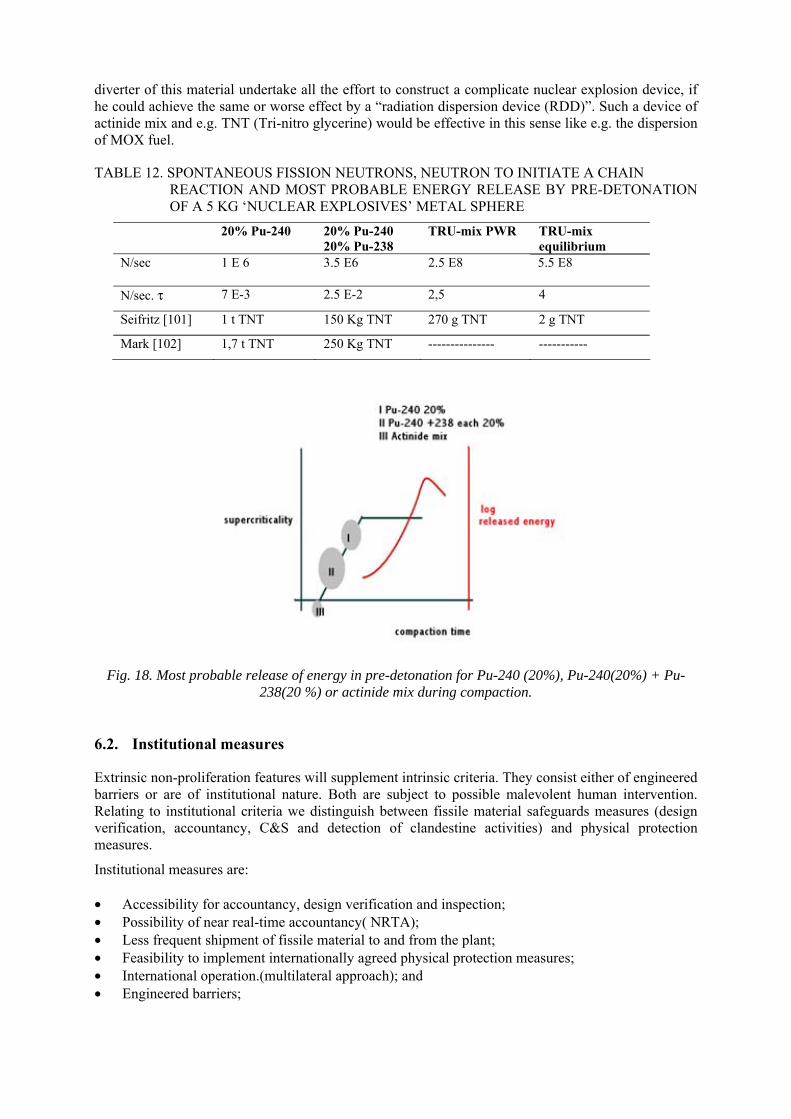
diverter of this material undertake all the effort to construct a complicate nuclear explosion device, if he could achieve the same or worse effect by a “radiation dispersion device (RDD)”. Such a device of actinide mix and e.g. TNT (Tri-nitro glycerine) would be effective in this sense like e.g. the dispersion of MOX fuel.
TABLE 12. SPONTANEOUS FISSION NEUTRONS, NEUTRON TO INITIATE A CHAIN REACTION AND MOST PROBABLE ENERGY RELEASE BY PRE-DETONATION OF A 5 KG ‘NUCLEAR EXPLOSIVES’ METAL SPHERE
20% Pu-240 20% Pu-240 20% Pu-238
TRU-mix PWR TRU-mix equilibrium
N/sec 1 E 6 3.5 E6 2.5 E8 5.5 E8
N/sec. τ 7 E-3 2.5 E-2 2,5 4
Seifritz [101] 1 t TNT 150 Kg TNT 270 g TNT 2 g TNT
Mark [102] 1,7 t TNT 250 Kg TNT --------------- -----------
Fig. 18. Most probable release of energy in pre-detonation for Pu-240 (20%), Pu-240(20%) + Pu-238(20 %) or actinide mix during compaction.
6.2. Institutional measures
Extrinsic non-proliferation features will supplement intrinsic criteria. They consist either of engineered barriers or are of institutional nature. Both are subject to possible malevolent human intervention. Relating to institutional criteria we distinguish between fissile material safeguards measures (design verification, accountancy, C&S and detection of clandestine activities) and physical protection measures.
Institutional measures are: • Accessibility for accountancy, design verification and inspection; • Possibility of near real-time accountancy( NRTA); • Less frequent shipment of fissile material to and from the plant; • Feasibility to implement internationally agreed physical protection measures; • International operation.(multilateral approach); and • Engineered barriers;
Simple process design to detect clandestine operation; Reduced number of in- and outlets to plant complex. Site concepts for an advanced reprocessing plant there are different plant concepts under discussion, which impact on the safeguard ability of a P&T plant as well as on the processes with intrinsic proliferation features.
The integration of a pyro-partitioning process facility into the nuclear reactor containment ( as shown for the integrated fast rector, IFR or the molten salt breeder reactor, MSBR previously operated in Idaho and Oak Ridge, both USA) eases nuclear material safeguards.
Three envisaged concepts for spent reactor nuclear fuel processing:
• The Integral Fast Reactor, IFR. (To the EBR II in Idaho a fuel processing plant was integral part of the reactor);
• An extension of this concept would be one plant in a nuclear park serving several nuclear power stations on-site; and
• A central reprocessing plant, which corresponds to the present large scale PUREX plants in Sellafield or in La Hague.
In order to attain the set limits for unaccounted material in inventory changes, material balances, etc., a lower material hold-up in a plant would require less stringent measures. If all concepts operate with the same process, the hold-up is proportional to the plant throughput. Not only is this an advantage of the IFR with its smaller plant. There is no shipment of fuel to the integrated plant (except for natural U or Th to balance the fissioned material). The same containment houses power station and fuel make-up, which eases containment and surveillance measures, C&S. No shipper receiver - difference has to be considered. The shipper – receiver differences can be disregarded also for the nuclear park, if the on-site transfer is physically integrated.
If there will be transport of spent and fresh fuel from different power stations to the distant central reprocessing plant, additional safeguard measures will be required to recognize a shipper-receiver difference. Another disadvantage of this concept is due to the fact, that before transport of fuel through public areas the fuel has to be cooled for a longer period: The economical drawback, part of fissile 241Pu will decay into more difficult to separate Am and the decay of the neutron emitting 242Cm reduces the proliferation resistance of the actinide mix. The out-of-pile fuel stock increases. More serious from the view point of safeguards is the reduced proliferation resistance for the central reprocessing plant concept: Only if the spent fuel is reprocessed in due time it will contain enough spontaneously fissionable nuclides to prevent, that the resulting product can be turned into a nuclear explosive. Contrary to the aqueous processes the pyro-chemical process can treat fuel of shorter cooling, because of radiation resistance of its chemical reactants.
In summing up: the two first concepts are likely to be safeguarded by C&S and near real time accountancy, NRTA, which accounts for the fissile material in all process units as required anyway by the fissile material tracking system for criticality control inside the plant. Only the third concept being analogue to a large scale PUREX plant is faced with the shipper-receiver difference determination, which requires a verification of the fissile material input measurement and delivers a product less resistant against misuse as nuclear explosive.
6.3. Comparison of aqueous- and pyro- processing in view of non-proliferation
For an aqueous partitioning plant using a continuous process (as envisaged by GANEX) the nuclear material safeguards regime will base on the existing concept for PUREX plants. Of course in the process control as well in the fissile material accountancy the minor actinide determination has to be included.
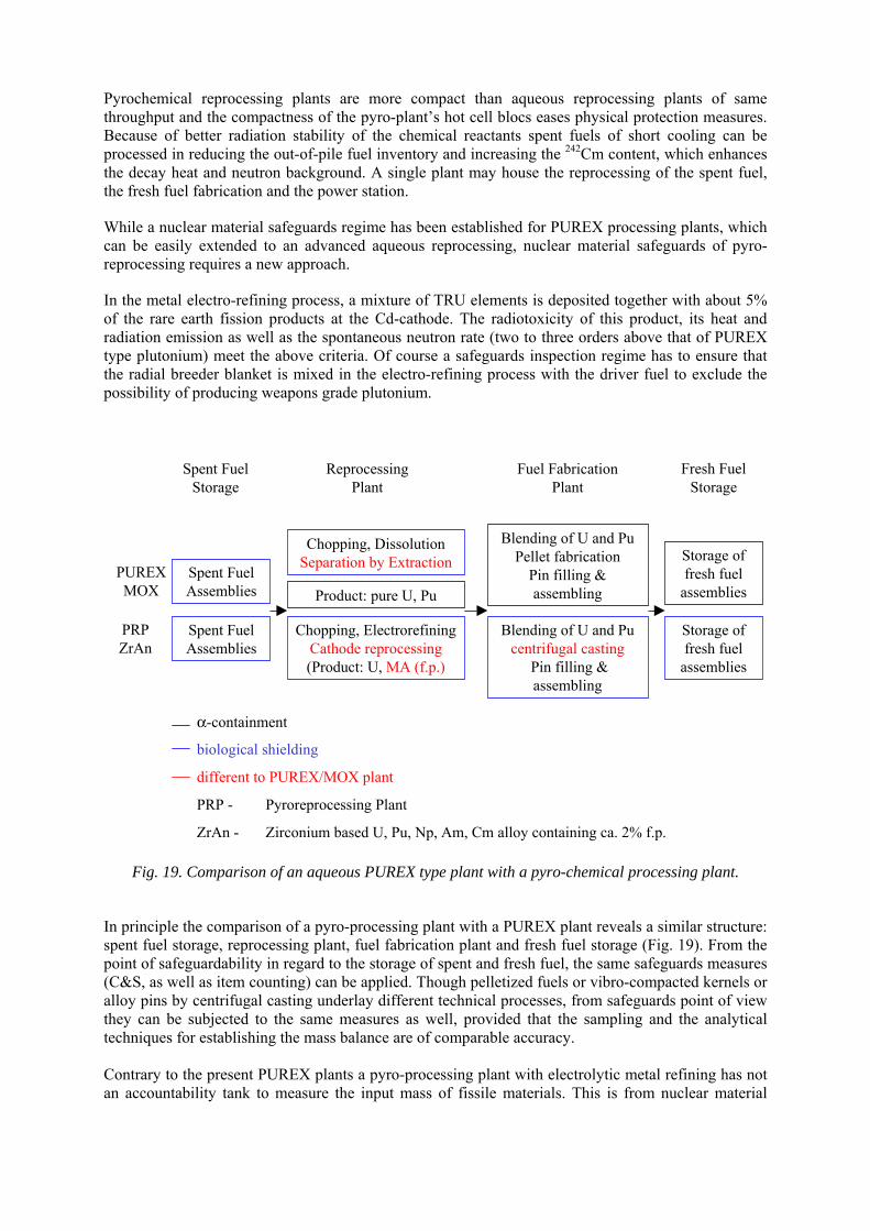
Pyrochemical reprocessing plants are more compact than aqueous reprocessing plants of same throughput and the compactness of the pyro-plant’s hot cell blocs eases physical protection measures. Because of better radiation stability of the chemical reactants spent fuels of short cooling can be processed in reducing the out-of-pile fuel inventory and increasing the 242Cm content, which enhances the decay heat and neutron background. A single plant may house the reprocessing of the spent fuel, the fresh fuel fabrication and the power station.
While a nuclear material safeguards regime has been established for PUREX processing plants, which can be easily extended to an advanced aqueous reprocessing, nuclear material safeguards of pyro-reprocessing requires a new approach.
In the metal electro-refining process, a mixture of TRU elements is deposited together with about 5% of the rare earth fission products at the Cd-cathode. The radiotoxicity of this product, its heat and radiation emission as well as the spontaneous neutron rate (two to three orders above that of PUREX type plutonium) meet the above criteria. Of course a safeguards inspection regime has to ensure that the radial breeder blanket is mixed in the electro-refining process with the driver fuel to exclude the possibility of producing weapons grade plutonium.
Spent FuelStorage
ReprocessingPlant
Fuel FabricationPlant
Fresh FuelStorage
PUREXMOX
PRPZrAn
Spent FuelAssemblies
Spent FuelAssemblies
Chopping, DissolutionSeparation by Extraction
Chopping, ElectrorefiningCathode reprocessing(Product: U, MA (f.p.)
Product: pure U, Pu
Blending of U and PuPellet fabrication
Pin filling &assembling
Blending of U and Pucentrifugal casting
Pin filling &assembling
Storage offresh fuel
assemblies
Storage offresh fuel
assemblies
α-containment
biological shielding
different to PUREX/MOX plant
PRP - Pyroreprocessing Plant
ZrAn - Zirconium based U, Pu, Np, Am, Cm alloy containing ca. 2% f.p.
Fig. 19. Comparison of an aqueous PUREX type plant with a pyro-chemical processing plant.
In principle the comparison of a pyro-processing plant with a PUREX plant reveals a similar structure: spent fuel storage, reprocessing plant, fuel fabrication plant and fresh fuel storage (Fig. 19). From the point of safeguardability in regard to the storage of spent and fresh fuel, the same safeguards measures (C&S, as well as item counting) can be applied. Though pelletized fuels or vibro-compacted kernels or alloy pins by centrifugal casting underlay different technical processes, from safeguards point of view they can be subjected to the same measures as well, provided that the sampling and the analytical techniques for establishing the mass balance are of comparable accuracy. Contrary to the present PUREX plants a pyro-processing plant with electrolytic metal refining has not an accountability tank to measure the input mass of fissile materials. This is from nuclear material
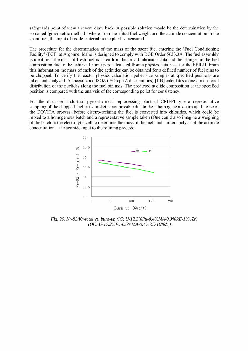
safeguards point of view a severe draw back. A possible solution would be the determination by the so-called ‘gravimetric method’, where from the initial fuel weight and the actinide concentration in the spent fuel, the input of fissile material to the plant is measured.
The procedure for the determination of the mass of the spent fuel entering the ‘Fuel Conditioning Facility’ (FCF) at Argonne, Idaho is designed to comply with DOE Order 5633.3A. The fuel assembly is identified, the mass of fresh fuel is taken from historical fabricator data and the changes in the fuel composition due to the achieved burn up is calculated from a physics data base for the EBR-II. From this information the mass of each of the actinides can be obtained for a defined number of fuel pins to be chopped. To verify the reactor physics calculation pellet size samples at specified positions are taken and analyzed. A special code ISOZ (lSOtope Z-distributions) [103] calculates a one dimensional distribution of the nuclides along the fuel pin axis. The predicted nuclide composition at the specified position is compared with the analysis of the corresponding pellet for consistency.
For the discussed industrial pyro-chemical reprocessing plant of CRIEPI–type a representative sampling of the chopped fuel in its basket is not possible due to the inhomogeneous burn up. In case of the DOVITA process; before electro-refining the fuel is converted into chlorides, which could be mixed to a homogenous batch and a representative sample taken (One could also imagine a weighing of the batch in the electrolytic cell to determine the mass of the melt and – after analysis of the actinide concentration – the actinide input to the refining process.)
13
13.5
14
14.5
15
15.5
16
0 50 100 150 200
OC IC
Burn-up (Gwd/t)
Kr-83 /
Kr-to
tal (%
)
Fig. 20. Kr-83/Kr-total vs. burn-up (IC: U-12.3%Pu-0.4%MA-0.3%RE-10%Zr) (OC: U-17.2%Pu-0.5%MA-0.4%RE-10%Zr).
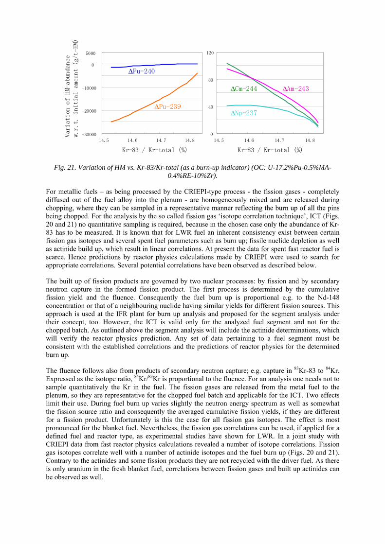
-30000
-20000
-10000
0
5000
14.5 14.6 14.7 14.8
ΔPu-240
ΔPu-239
0
40
80
120
14.5 14.6 14.7 14.8
ΔNp-237
ΔCm-244 ΔAm-243
Kr-83 / Kr-total (%) Kr-83 / Kr-total (%)
Variation o
f HM-abundance
w.r.t. initia
l am
ount (g/t-HM)
Fig. 21. Variation of HM vs. Kr-83/Kr-total (as a burn-up indicator) (OC: U-17.2%Pu-0.5%MA-0.4%RE-10%Zr).
For metallic fuels – as being processed by the CRIEPI-type process - the fission gases - completely diffused out of the fuel alloy into the plenum - are homogeneously mixed and are released during chopping, where they can be sampled in a representative manner reflecting the burn up of all the pins being chopped. For the analysis by the so called fission gas ‘isotope correlation technique’, ICT (Figs. 20 and 21) no quantitative sampling is required, because in the chosen case only the abundance of Kr-83 has to be measured. It is known that for LWR fuel an inherent consistency exist between certain fission gas isotopes and several spent fuel parameters such as burn up; fissile nuclide depletion as well as actinide build up, which result in linear correlations. At present the data for spent fast reactor fuel is scarce. Hence predictions by reactor physics calculations made by CRIEPI were used to search for appropriate correlations. Several potential correlations have been observed as described below.
The built up of fission products are governed by two nuclear processes: by fission and by secondary neutron capture in the formed fission product. The first process is determined by the cumulative fission yield and the fluence. Consequently the fuel burn up is proportional e.g. to the Nd-148 concentration or that of a neighbouring nuclide having similar yields for different fission sources. This approach is used at the IFR plant for burn up analysis and proposed for the segment analysis under their concept, too. However, the ICT is valid only for the analyzed fuel segment and not for the chopped batch. As outlined above the segment analysis will include the actinide determinations, which will verify the reactor physics prediction. Any set of data pertaining to a fuel segment must be consistent with the established correlations and the predictions of reactor physics for the determined burn up.
The fluence follows also from products of secondary neutron capture; e.g. capture in 83Kr-83 to 84Kr. Expressed as the isotope ratio, 84Kr/83Kr is proportional to the fluence. For an analysis one needs not to sample quantitatively the Kr in the fuel. The fission gases are released from the metal fuel to the plenum, so they are representative for the chopped fuel batch and applicable for the ICT. Two effects limit their use. During fuel burn up varies slightly the neutron energy spectrum as well as somewhat the fission source ratio and consequently the averaged cumulative fission yields, if they are different for a fission product. Unfortunately is this the case for all fission gas isotopes. The effect is most pronounced for the blanket fuel. Nevertheless, the fission gas correlations can be used, if applied for a defined fuel and reactor type, as experimental studies have shown for LWR. In a joint study with CRIEPI data from fast reactor physics calculations revealed a number of isotope correlations. Fission gas isotopes correlate well with a number of actinide isotopes and the fuel burn up (Figs. 20 and 21). Contrary to the actinides and some fission products they are not recycled with the driver fuel. As there is only uranium in the fresh blanket fuel, correlations between fission gases and built up actinides can be observed as well.
The consistency of the physics calculation is checked with the results from the spent fuel segment analysis, which also identifies the chopped fuel as being from inner or outer core. Since they are only related to the analyzed fuel segment, they will not verify the input of the total chopped fuel batch as it does the fission gas correlations, which are released from all parts of the fuel. Nevertheless, the small sample data as obtained from fuel segments will verify the reactor physics calculations as far as pertaining to the declared reactor and portion of fuel. Any data set of a post irradiation examination must fit the established set of correlations obtained earlier for this case. However, the achieved burn-up and consequently the remaining actinide concentration of all the chopped fuel will not follow from this comparison. Only the fission gases represent the average of the chopped fuel i.e. the total of the chopped fuel segments being reprocessed. The experience of LWR post irradiation examination of fuel segments proved to be very effective in serving as bench mark data for testing reactor physics codes and cross-section libraries, thus improving the accuracy of reactor physics predictions. We can expect that as accumulated data of the analyzed fuel segments become available, also reactor physics codes of fast reactors will gradually benefit from that.
In the following the analytical techniques are summarized, which are used for actinide measurement in bulk material, in recycled material with medium concentration and in waste ranging from 0.01 to 1 %.
In the DUPIC process - as being developed in South Korea - we have a situation comparable to an electrochemical processing plant. Spent PWR fuel is pulverized by multiple reduction/oxidation and re-fabricated as CANDU fuel. There is also no analogue input measurement possible like in a PUREX plant. The solution is a quantitative measurement of the neutrons from spontaneous fission of Cm (the dominant fission source in the processed spent fuel is Cm). From the homogenized powder a sample is destructively analyzed for its actinide concentrations. Under the assumption of having analyzed a representative sample the true input mass of U and Pu is obtained
The neutron emission of the fuel processed in the electro-chemical processing plant has spontaneous fission sources of mainly Cm isotopes and not dominant (α, n) reaction with lithium in the electrolyte. With neutron coincidence counting the latter contribution is possible to discriminate. The spontaneous fission neutrons (for a 3 y cooled fuel) stem about 80% from 244Cm and 20% from 242Cm (with extended recycling 246Cm becomes a contributor as well). The contribution of 240Pu is less than 0.5%, as computed from reactor physics calculation by CRIEPI. Appropriate counters have been developed to measure the absolute counting rate of defined packages. If 242Cm is the dominate source its mass is obtained directly.
For the electro- chemical processing plant the neutron measurement of chopped fuel in its basket seems feasible, too. By this a verification of the absolute value for one actinide element can be obtained. A comparison with the predicted Cm concentration in the spent fuel would verify indirectly the initial fuel mass. Between the two main fission sources 242Cm and 244Cm one cannot distinguish. If the cooling time of the reprocessed fuel is less than 200 days, then 242Cm spontaneous fission would dominate the n-counting rate. Nevertheless, the predicted fission neutrons can be compared with the measured ones. Hence the verification of the declared 244Cm +242Cm mass also verifies inherently the declared fuel mass - within the accuracy of the 242Cm + 244Cm prediction.
Since the fuel in the basket is not homogenized, an analysis of a sample would not reflect the average actinide concentration. By this the post irradiation mass of the other actinides cannot be obtained directly - analogue to the DUPIC plant.
The n-accounting is a prospective method to measure actinide in transfer of material, where the actinide (An) composition is not changed in between, in discarded waste or in recycled material.
Active neutron interrogation measures total fissile material and differentiates not for fission sources. As a routine measure it already checks for 235U and Pu in residues of dissolution at the PUREX plant of AREVA NC (formerly COGÉMA, France). In an electrochemical processing plant all material will contain Cm, which masques the presence of Pu, when measured by neutron coincidence counting. A
combination of active and passive neutron counting, verifies the predicted ratio of Cm to fissile nuclides. In waste streams active interrogation ascertains the absence of Pu larger than expected from the neutron coincidence count for Cm.
High resolution gamma spectroscopy seems not to be applicable for material balancing, because all materials contain a too high content of gamma emitting fission products. Hybrid K-edge densitometry (combination of K-edge densitometry and X ray fluorescence) measures the concentration of all actinides in question. Lacking is the isotope analysis. If required, thermal ionization mass spectrometry is the analytical technique of choice. The conventional techniques to measure volume, weight and density of the material are not discussed in this report, although they are not trivial.
Although non-destructive testing (NDT|) can determine actinides in the product stream to a few per mille of precision, bias control of NDT by destructive analysis, destructive analysis is required periodically. An actinide isotope analysis is needed, whenever material batches are mixed or altered during processing. The analytical techniques are identical to those applied in controlling PUREX reprocessing. Because of the isobars: Pu/241Am, Pu/Am/242Cm, and Am/243Cm a separation of the elements has to take place in a separate laboratory before mass spectrometric analysis. The accuracy for the most abundant isotopes is below 0.01 % far better than nuclear material control needs.
As far as possible any institutional material mass control should make use of the authenticated operator’s measurement systems. This includes scales, volume meters and NDT (neutron coincidence counting, active neutron interrogation). Bias control of NDT and traces of actinides in recycled material and in products could be made in an on-site laboratory dedicated to verification measurements as presently used for the PUREX plants. The isotope analysis of fission gas should follow the technique as formerly employed at EBR-II for fission gas tagging.
6.4. Proliferation resistance of geologic repository
A P&T concept still produces nuclear waste to be disposed of in a geological repository. In general, safeguard monitoring may be required for a repository or for an interim storage, which will result in long term burden and risk on future generations, unless waste materials meet international safeguards termination (IST) criteria. To qualify for IST, nuclear material contained in the waste must be removed or diluted in such a way that it is no longer usable for any nuclear activity relevant from the view point of safeguards, or has become practicably irrecoverable. Among TRU isotopes, critical masses are relatively small for 239Pu (10kg), 237Np (56kg) and 241Am (59 kg) (Table 6-3). Another observation related to proliferation resistance is the ratio of 238Pu to 239Pu in the HLW from a partitioning process. Proliferation resistance of interim storage and geologic disposal can be improved by reduction of fissionable nuclides. An increase in decay heat and neutron emission rates due to Cm isotopes and 238Pu (by built-up from 237Np) in spent fuels increases its proliferation resistance as well.
Figure 22 shows the masses of actinides in a geologic repository for vitrified high-level wastes from PUREX reprocessing of commercial spent nuclear fuel, normalized by the bare-sphere critical mass (BSCM) shown in Table 13. The fissile uranium isotope fraction is around 10% or less at any time in the vitrified HLW in the repository. Recovering uranium in HLW for weapons production would not be significantly more attractive than mining natural uranium for isotopic enrichment.
Figure 22 shows that about 300 BSCM of 237Np and 140 BSCM of plutonium exist in the repository. All of the plutonium isotopes, including the even isotopes, have fast-fission cross sections which are relatively large, and thus all of the plutonium isotopes have small BSCM, as shown in Table 13. All isotopic blends of plutonium can in principle be used to make explosives.
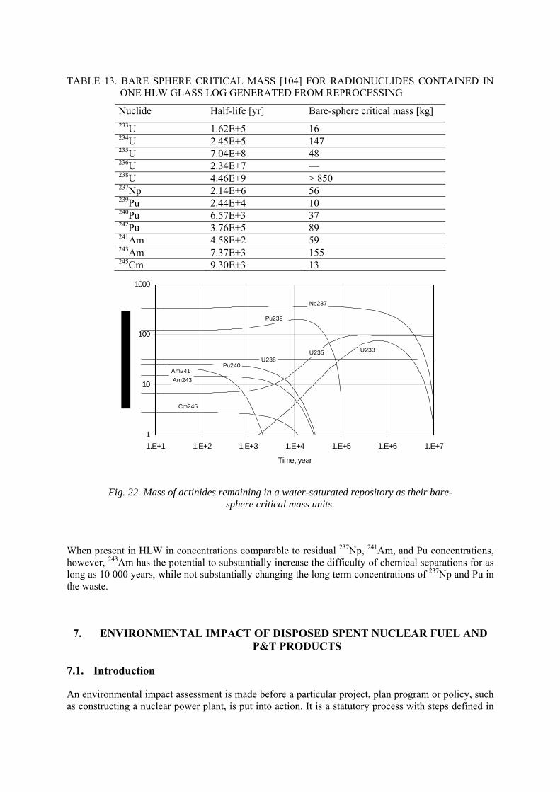
TABLE 13. BARE SPHERE CRITICAL MASS [104] FOR RADIONUCLIDES CONTAINED IN ONE HLW GLASS LOG GENERATED FROM REPROCESSING
Nuclide Half-life [yr] Bare-sphere critical mass [kg] 233U 1.62E+5 16 234U 2.45E+5 147 235U 7.04E+8 48 236U 2.34E+7 –– 238U 4.46E+9 > 850 237Np 2.14E+6 56 239Pu 2.44E+4 10 240Pu 6.57E+3 37 242Pu 3.76E+5 89 241Am 4.58E+2 59 243Am 7.37E+3 155 245Cm 9.30E+3 13
1
10
100
1000
1.E+1 1.E+2 1.E+3 1.E+4 1.E+5 1.E+6 1.E+7
Time, year
Np237
Pu239
U235 U233
U238Pu240
Am241
Am243
Cm245
Fig. 22. Mass of actinides remaining in a water-saturated repository as their bare-sphere critical mass units.
When present in HLW in concentrations comparable to residual 237Np, 241Am, and Pu concentrations, however, 243Am has the potential to substantially increase the difficulty of chemical separations for as long as 10 000 years, while not substantially changing the long term concentrations of 237Np and Pu in the waste.
7. ENVIRONMENTAL IMPACT OF DISPOSED SPENT NUCLEAR FUEL AND P&T PRODUCTS
7.1. Introduction
An environmental impact assessment is made before a particular project, plan program or policy, such as constructing a nuclear power plant, is put into action. It is a statutory process with steps defined in
detail in national laws and regulations. Besides analyzing effects potentially caused by a planned project, its objective is to establish communication to and involvement of the public already in the initial steps of the overall project. The thrust of the laws and regulations is to ensure that balanced decision making regarding the environment occurs in the total public interest.
In general, the environmental impact assessment has to identify and collect relevant information, analyze it and predict potential impacts of the project on humans and the environment, proposing at the same time measures in order to prevent or minimize possible consequences. The gathered information has physical, chemical, biological and socioeconomic character and should serve for an objective judgment of the planned project.
Impacts of P&T activities on physical-chemical and socioeconomic environments can be subdivided into three groups as follows:
1. Radionuclides released from P&T facilities, interim storage facilities and a geologic repository for high-level waste (HLW) resulting from partitioning processes could cause adverse effects on public health. Radionuclides can be released as a result of a normal operation or accident conditions. Because the P&T facilities deal with thermally fissile materials, a criticality accident is also included;
2. P&T activities could cause significant institutional and monetary burdens because deployment of the P&T system will be a long term project (at least half a century or longer). It is necessary to emphasize that in a comparison of the two strategies – without and with P&T deployment – all kinds of existing wastes should be taken into account. At present, there is a general consensus that P&T can reduce the potential toxicity of the HLW, the public dose from the repository, and the total volume of radioactive wastes. Thus means that the repository space can be more effectively utilized by P&T deployment; and
3. Socioeconomic impacts have to be considered in the context of proliferation resistance. More detailed information is presented in Section 6 and a discussion in Section 9.
To minimize potential impacts, the following measures can be applied:
• careful site selection for geological repositories (natural barrier); • application of waste forms with high mechanical stability and long term durability; and • application of design features (engineered barriers) capable of preventing or retarding the
release of radionuclides into the accessible biosphere. •
The deployment of various P&T concepts (originally developed as an alternative to geological disposal of HLW) does not mean to back away from long term geological repositories for HLW [104], [105]. On the other hand, P&T systems can affect costs of the geological disposal significantly; however, these costs have to be considered in conjunction with costs for deployment of P&T systems.
7.2. Definition of environmental impact for comparison of P&T processes
Environmental impact can be expressed in various ways. The most common procedure to show that the planned project will not cause unacceptable effects to humans and, consequently, to the environment, is to perform a safety assessment study, which will determine the potential exposure incurred by an individual or a group of individuals (the critical group) as a result of radionuclides released from the repository. The impact is usually expressed as a risk level of health effects during an average lifetime or as dose equivalent for a period of time of one year, i.e., in Sv/y (Sievert per year). It is a general consensus that for protecting the public health a limit of 1mSv/y must not be exceeded. As this limit covers exposures from all anthropogenic sources (except medical exposures), it is usually apportioned among the respective sources; to the geological disposal a dose equivalent of 0.1-0.3 mSv is typically allocated.
In most safety assessments for deep geological disposal facilities, the critical scenario is represented by repository saturation, degradation of the canister and leaching of radionuclides from the waste. Leached radionuclides are thereafter, transported from the geosphere downstream to the accessible biosphere, where they can be ingested, e.g., in form of drinking water. The disposal system is deemed as acceptable if the environmental impact, expressed in the annual dose equivalent, is within the authorized limits.
Sometimes it is useful to stress the role of individual radionuclides contained in the waste since some, less radiotoxic but worse secured, can represent higher risk than more radiotoxic and better secured ones. For this reason it is necessary to provide a differentiation using the so called Annual limits of intake (ALI) expressed in Bq, which can be converted to dose equivalent by means of a dose conversion factor (in Sv/Bq). In some of our figures this diversity is presented by an “ALI ingestion hazard index” defined as the ratio of radioactivity in Bq and the ALI value of a nuclide, also in Bq.
From other figures it can be seen that the radiotoxicity of radionuclides can also be characterized as quantity of water (in m3) necessary to dilute the radioactivity of a nuclide (in Bq) in order to achieve a standard for drinking water (in Bq/m3). Radiotoxicity of radionuclides is sometimes substituted by “ingestion hazard index”; its definition is identical with that of radiotoxicity, i.e., total volume of water required to dilute all the radionuclides in a unit mass of waste down to their ALI values.
7.3. Environmental impacts of various spent fuel strategies
7.3.1. Environmental impact for direct disposal of spent nuclear fuel
Geologic disposal of the spent fuel without recycle is being considered in various countries. Significant progress in development of a water-saturated geologic repository is attained in Sweden and Finland. In the USA, where operation is expected to start within the next decade, due to the geological environment (tuff) the repository is considered as partly water-saturated.
In this section, the environmental impact of spent fuel from LWRs with no recycle (i.e., direct disposal of spent fuel) is assessed for a water saturated repository. Assumed is burn-up of 45 GWd/ton, package failure time 10 000 years, pore velocity of the groundwater flow 1 m/year, porosity of the host rock 10% , and diffusion coefficient in the host rock 3E-2 m2/year. Solubility of various elements in the groundwater is summarized in Table 14.
TABLE 14. ESTIMATED SOLUBILITY OF ELEMENTS IN PORE GROUNDWATER OF TYPICAL COMPOSITION
Element solubility
mol/m3
Element solubility
mol/m3
Element solubility
mol/m3
Element solubility
mol/m3
Se 3.0E-06 Sn 1.0E-03 Ra 1.0E-09 Np 2.0E-05
Zr 1.0E-03 Cs high Ac 2.0E-04 Pu 3.0E-05
Nb 1.0E-01 I high Th 5.0E-03 Am 2.0E-04
Tc 4.0E-05 Sm 2.0E-04 Pa 2.0E-05 Cm 2.0E-04
Pd 1.0E-06 Pb 2.0E-03 U 8.0E-06
Radionuclides in the spent fuel are categorized into three groups: (1) TRU nuclides and their daughters, (2) fission products (FP) nuclides, and (3) natural uranium isotopes (238U and 235U) and their decay daughters. We include only groups (1) and (2) for radiotoxicity comparison because they represent the net impact generated as a result of nuclear power production.
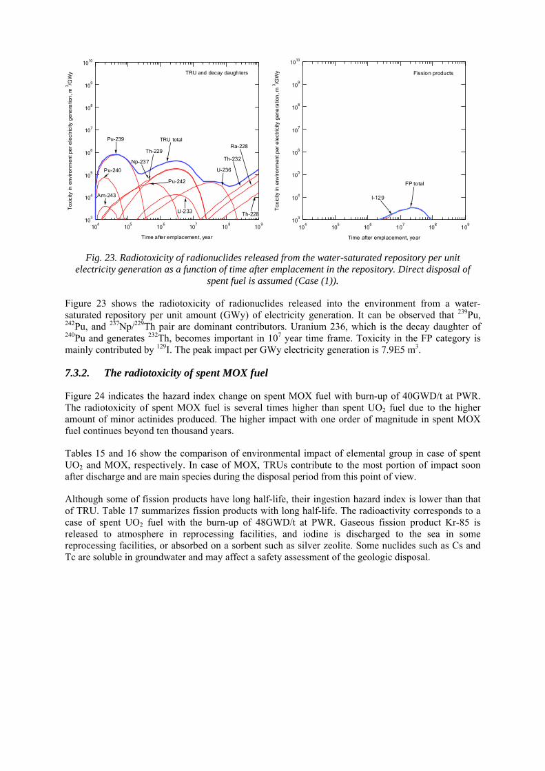
103
104
105
106
107
108
109
1010
Tox
icity
in e
nviro
nmen
t per
ele
ctric
ity g
ene
ratio
n, m
3 /GW
y
104
105
106
107
108
109
Time after emplacement, year
TRU and decay daughters
TRU total
U-236
Th-232
Ra-228
Th-228
Pu-242
Am-243
Pu-239
Np-237
U-233
Th-229
Pu-240
103
104
105
106
107
108
109
1010
Tox
icity
in e
nviro
nmen
t per
ele
ctric
ity g
ene
ratio
n, m
3 /GW
y
104
105
106
107
108
109
Time after emplacement, year
Fission products
FP total
I-129
Fig. 23. Radiotoxicity of radionuclides released from the water-saturated repository per unit electricity generation as a function of time after emplacement in the repository. Direct disposal of
spent fuel is assumed (Case (1)).
Figure 23 shows the radiotoxicity of radionuclides released into the environment from a water-saturated repository per unit amount (GWy) of electricity generation. It can be observed that 239Pu, 242Pu, and 237Np/229Th pair are dominant contributors. Uranium 236, which is the decay daughter of 240Pu and generates 232Th, becomes important in 107 year time frame. Toxicity in the FP category is mainly contributed by 129I. The peak impact per GWy electricity generation is 7.9E5 m3.
7.3.2. The radiotoxicity of spent MOX fuel
Figure 24 indicates the hazard index change on spent MOX fuel with burn-up of 40GWD/t at PWR. The radiotoxicity of spent MOX fuel is several times higher than spent UO2 fuel due to the higher amount of minor actinides produced. The higher impact with one order of magnitude in spent MOX fuel continues beyond ten thousand years.
Tables 15 and 16 show the comparison of environmental impact of elemental group in case of spent UO2 and MOX, respectively. In case of MOX, TRUs contribute to the most portion of impact soon after discharge and are main species during the disposal period from this point of view.
Although some of fission products have long half-life, their ingestion hazard index is lower than that of TRU. Table 17 summarizes fission products with long half-life. The radioactivity corresponds to a case of spent UO2 fuel with the burn-up of 48GWD/t at PWR. Gaseous fission product Kr-85 is released to atmosphere in reprocessing facilities, and iodine is discharged to the sea in some reprocessing facilities, or absorbed on a sorbent such as silver zeolite. Some nuclides such as Cs and Tc are soluble in groundwater and may affect a safety assessment of the geologic disposal.
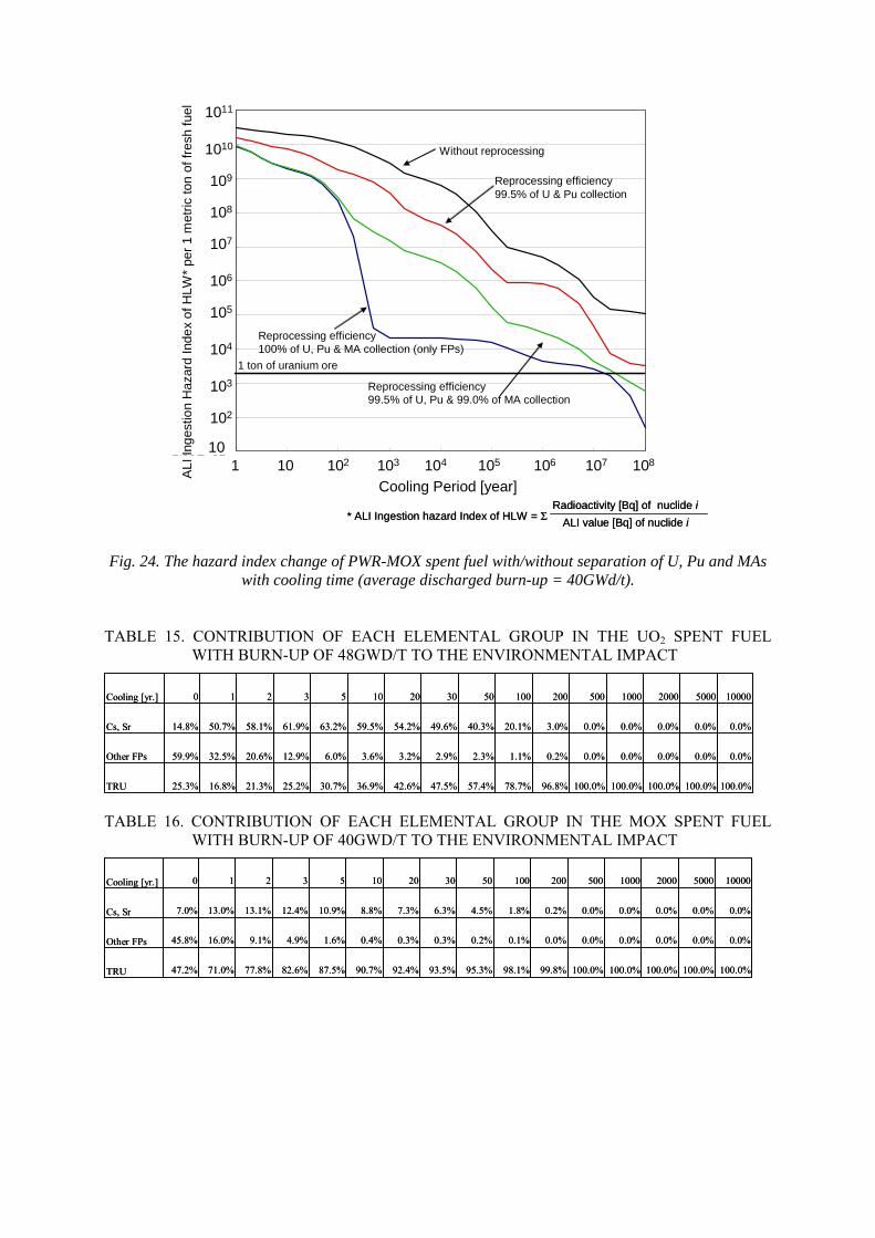
1.00E+01
1.00E+02
1.00E+03
1.00E+04
1.00E+05
1.00E+06
1.00E+07
1.00E+08
1.00E+09
1.00E+10
1.00E+11
1.0E+00 1.0E+01 1.0E+02 1.0E+03 1.0E+04 1.0E+05 1.0E+06 1.0E+07 1.0E+08
10
102
103
104
105
106
107
108
109
1010
AL
I Ing
estio
n H
aza
rd I
nde
x o
f HLW
* pe
r 1
met
ric t
on o
f fre
sh f
uel
Cooling Period [year]
* ALI Ingestion hazard Index of HLW = ΣRadioactivity [Bq] of nuclide i
ALI value [Bq] of nuclide i
Without reprocessing
Reprocessing efficiency99.5% of U & Pu collection
Reprocessing efficiency99.5% of U, Pu & 99.0% of MA collection
Reprocessing efficiency100% of U, Pu & MA collection (only FPs)
1 ton of uranium ore
1011
1 10 102 103 104 105 106 107 108
Cooling Period [year]
Fig. 24. The hazard index change of PWR-MOX spent fuel with/without separation of U, Pu and MAs with cooling time (average discharged burn-up = 40GWd/t).
TABLE 15. CONTRIBUTION OF EACH ELEMENTAL GROUP IN THE UO2 SPENT FUEL WITH BURN-UP OF 48GWD/T TO THE ENVIRONMENTAL IMPACT
100.0%100.0%100.0%100.0%100.0%96.8%78.7%57.4%47.5%42.6%36.9%30.7%25.2%21.3%16.8%25.3%TRU
0.0%0.0%0.0%0.0%0.0%0.2%1.1%2.3%2.9%3.2%3.6%6.0%12.9%20.6%32.5%59.9%Other FPs
0.0%0.0%0.0%0.0%0.0%3.0%20.1%40.3%49.6%54.2%59.5%63.2%61.9%58.1%50.7%14.8%Cs, Sr
100005000200010005002001005030201053210Cooling [yr.]
TABLE 16. CONTRIBUTION OF EACH ELEMENTAL GROUP IN THE MOX SPENT FUEL WITH BURN-UP OF 40GWD/T TO THE ENVIRONMENTAL IMPACT
100.0%100.0%100.0%100.0%100.0%99.8%98.1%95.3%93.5%92.4%90.7%87.5%82.6%77.8%71.0%47.2%TRU
0.0%0.0%0.0%0.0%0.0%0.0%0.1%0.2%0.3%0.3%0.4%1.6%4.9%9.1%16.0%45.8%Other FPs
0.0%0.0%0.0%0.0%0.0%0.2%1.8%4.5%6.3%7.3%8.8%10.9%12.4%13.1%13.0%7.0%Cs, Sr
100005000200010005002001005030201053210Cooling [yr.]
100.0%100.0%100.0%100.0%100.0%99.8%98.1%95.3%93.5%92.4%90.7%87.5%82.6%77.8%71.0%47.2%TRU
0.0%0.0%0.0%0.0%0.0%0.0%0.1%0.2%0.3%0.3%0.4%1.6%4.9%9.1%16.0%45.8%Other FPs
0.0%0.0%0.0%0.0%0.0%0.2%1.8%4.5%6.3%7.3%8.8%10.9%12.4%13.1%13.0%7.0%Cs, Sr
100005000200010005002001005030201053210Cooling [yr.]
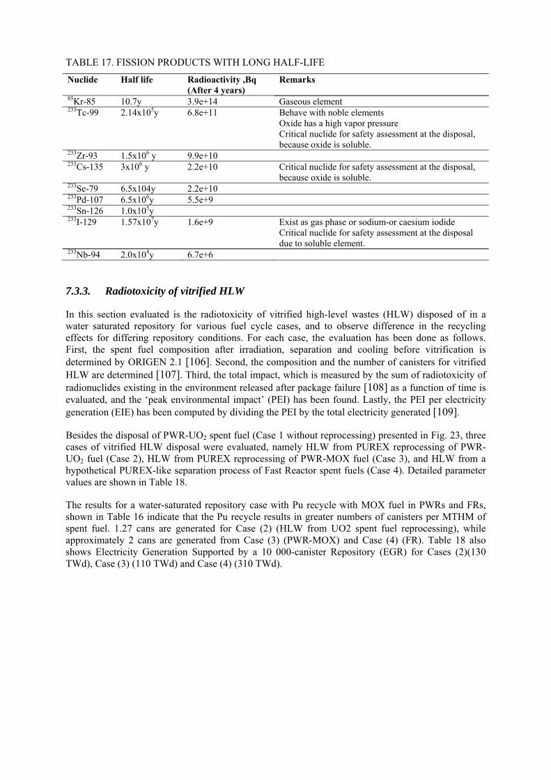
TABLE 17. FISSION PRODUCTS WITH LONG HALF-LIFE
Nuclide Half life Radioactivity ,Bq (After 4 years)
Remarks
85Kr-85 10.7y 3.9e+14 Gaseous element 233Tc-99 2.14x10⁵y 6.8e+11 Behave with noble elements
Oxide has a high vapor pressure Critical nuclide for safety assessment at the disposal, because oxide is soluble.
233Zr-93 1.5x10⁶ y 9.9e+10 233Cs-135 3x10⁶ y 2.2e+10 Critical nuclide for safety assessment at the disposal,
because oxide is soluble. 233Se-79 6.5x10⁴y 2.2e+10 233Pd-107 6.5x10⁶y 5.5e+9 233Sn-126 1.0x10⁵y 233I-129 1.57x10⁷y 1.6e+9 Exist as gas phase or sodium-or caesium iodide
Critical nuclide for safety assessment at the disposal due to soluble element.
233Nb-94 2.0x10⁴y 6.7e+6
7.3.3. Radiotoxicity of vitrified HLW
In this section evaluated is the radiotoxicity of vitrified high-level wastes (HLW) disposed of in a water saturated repository for various fuel cycle cases, and to observe difference in the recycling effects for differing repository conditions. For each case, the evaluation has been done as follows. First, the spent fuel composition after irradiation, separation and cooling before vitrification is determined by ORIGEN 2.1 [106]. Second, the composition and the number of canisters for vitrified HLW are determined [107]. Third, the total impact, which is measured by the sum of radiotoxicity of radionuclides existing in the environment released after package failure [108] as a function of time is evaluated, and the ‘peak environmental impact’ (PEI) has been found. Lastly, the PEI per electricity generation (EIE) has been computed by dividing the PEI by the total electricity generated [109].
Besides the disposal of PWR-UO2 spent fuel (Case 1 without reprocessing) presented in Fig. 23, three cases of vitrified HLW disposal were evaluated, namely HLW from PUREX reprocessing of PWR-UO2 fuel (Case 2), HLW from PUREX reprocessing of PWR-MOX fuel (Case 3), and HLW from a hypothetical PUREX-like separation process of Fast Reactor spent fuels (Case 4). Detailed parameter values are shown in Table 18.
The results for a water-saturated repository case with Pu recycle with MOX fuel in PWRs and FRs, shown in Table 16 indicate that the Pu recycle results in greater numbers of canisters per MTHM of spent fuel. 1.27 cans are generated for Case (2) (HLW from UO2 spent fuel reprocessing), while approximately 2 cans are generated from Case (3) (PWR-MOX) and Case (4) (FR). Table 18 also shows Electricity Generation Supported by a 10 000-canister Repository (EGR) for Cases (2)(130 TWd), Case (3) (110 TWd) and Case (4) (310 TWd).
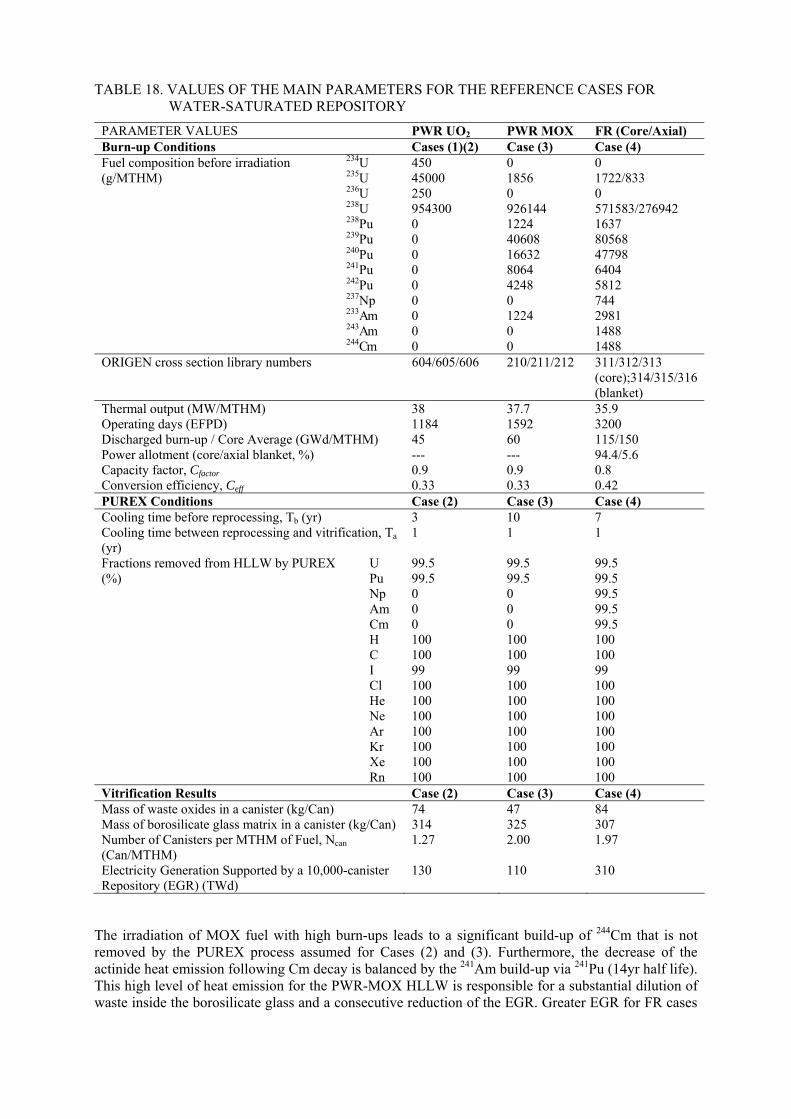
TABLE 18. VALUES OF THE MAIN PARAMETERS FOR THE REFERENCE CASES FOR WATER-SATURATED REPOSITORY
PARAMETER VALUES PWR UO2 PWR MOX FR (Core/Axial) Burn-up Conditions Cases (1)(2) Case (3) Case (4)
234U 450 0 0 235U 45000 1856 1722/833 236U 250 0 0 238U 954300 926144 571583/276942 238Pu 0 1224 1637 239Pu 0 40608 80568 240Pu 0 16632 47798 241Pu 0 8064 6404 242Pu 0 4248 5812 237Np 0 0 744 233Am 0 1224 2981 243Am 0 0 1488
Fuel composition before irradiation (g/MTHM)
244Cm 0 0 1488 ORIGEN cross section library numbers 604/605/606 210/211/212 311/312/313
(core);314/315/316 (blanket)
Thermal output (MW/MTHM) 38 37.7 35.9 Operating days (EFPD) 1184 1592 3200 Discharged burn-up / Core Average (GWd/MTHM) 45 60 115/150 Power allotment (core/axial blanket, %) --- --- 94.4/5.6 Capacity factor, Cfactor 0.9 0.9 0.8 Conversion efficiency, Ceff 0.33 0.33 0.42 PUREX Conditions Case (2) Case (3) Case (4) Cooling time before reprocessing, Tb (yr) 3 10 7 Cooling time between reprocessing and vitrification, Ta (yr)
1 1 1
U 99.5 99.5 99.5 Pu 99.5 99.5 99.5 Np 0 0 99.5 Am 0 0 99.5 Cm 0 0 99.5 H 100 100 100 C 100 100 100 I 99 99 99 Cl 100 100 100 He 100 100 100 Ne 100 100 100 Ar 100 100 100 Kr 100 100 100 Xe 100 100 100
Fractions removed from HLLW by PUREX (%)
Rn 100 100 100 Vitrification Results Case (2) Case (3) Case (4) Mass of waste oxides in a canister (kg/Can) 74 47 84 Mass of borosilicate glass matrix in a canister (kg/Can) 314 325 307 Number of Canisters per MTHM of Fuel, Ncan (Can/MTHM)
1.27 2.00 1.97
Electricity Generation Supported by a 10,000-canister Repository (EGR) (TWd)
130 110 310
The irradiation of MOX fuel with high burn-ups leads to a significant build-up of 244Cm that is not removed by the PUREX process assumed for Cases (2) and (3). Furthermore, the decrease of the actinide heat emission following Cm decay is balanced by the 241Am build-up via 241Pu (14yr half life). This high level of heat emission for the PWR-MOX HLLW is responsible for a substantial dilution of waste inside the borosilicate glass and a consecutive reduction of the EGR. Greater EGR for FR cases
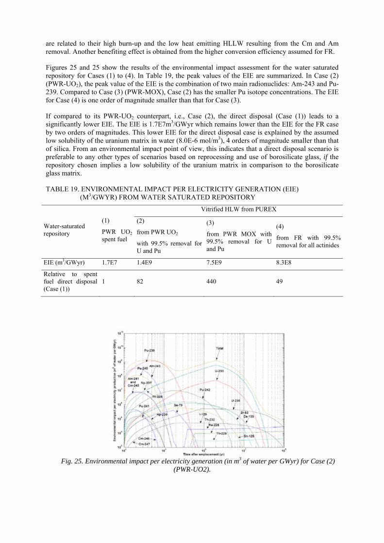
are related to their high burn-up and the low heat emitting HLLW resulting from the Cm and Am removal. Another benefiting effect is obtained from the higher conversion efficiency assumed for FR.
Figures 25 and 25 show the results of the environmental impact assessment for the water saturated repository for Cases (1) to (4). In Table 19, the peak values of the EIE are summarized. In Case (2) (PWR-UO2), the peak value of the EIE is the combination of two main radionuclides: Am-243 and Pu-239. Compared to Case (3) (PWR-MOX), Case (2) has the smaller Pu isotope concentrations. The EIE for Case (4) is one order of magnitude smaller than that for Case (3).
If compared to its PWR-UO2 counterpart, i.e., Case (2), the direct disposal (Case (1)) leads to a significantly lower EIE. The EIE is 1.7E7m3/GWyr which remains lower than the EIE for the FR case by two orders of magnitudes. This lower EIE for the direct disposal case is explained by the assumed low solubility of the uranium matrix in water (8.0E-6 mol/m3), 4 orders of magnitude smaller than that of silica. From an environmental impact point of view, this indicates that a direct disposal scenario is preferable to any other types of scenarios based on reprocessing and use of borosilicate glass, if the repository chosen implies a low solubility of the uranium matrix in comparison to the borosilicate glass matrix.
TABLE 19. ENVIRONMENTAL IMPACT PER ELECTRICITY GENERATION (EIE) (M3/GWYR) FROM WATER SATURATED REPOSITORY
Vitrified HLW from PUREX
Water-saturated repository
(1)
PWR UO2 spent fuel
(2)
from PWR UO2
with 99.5% removal for U and Pu
(3)
from PWR MOX with 99.5% removal for U and Pu
(4)
from FR with 99.5% removal for all actinides
EIE (m3/GWyr) 1.7E7 1.4E9 7.5E9 8.3E8
Relative to spent fuel direct disposal (Case (1))
1 82 440 49
Fig. 25. Environmental impact per electricity generation (in m3 of water per GWyr) for Case (2)
(PWR-UO2).
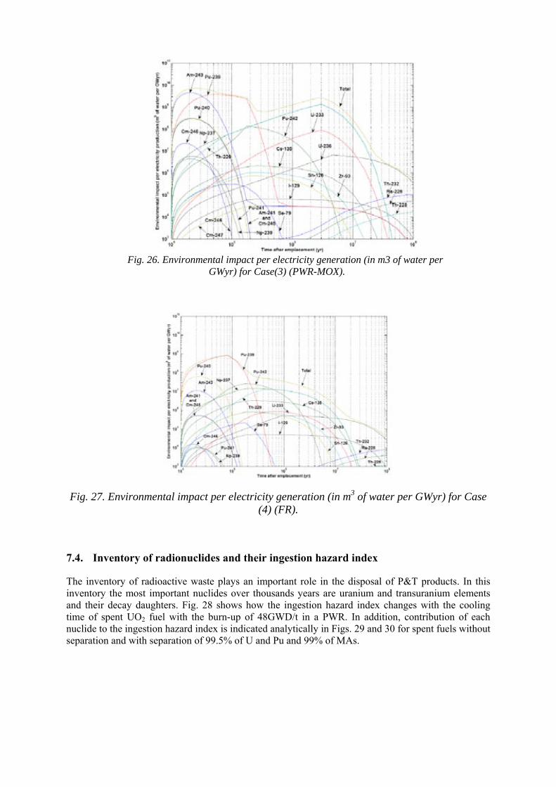
Fig. 26. Environmental impact per electricity generation (in m3 of water per
GWyr) for Case(3) (PWR-MOX).
Fig. 27. Environmental impact per electricity generation (in m3 of water per GWyr) for Case (4) (FR).
7.4. Inventory of radionuclides and their ingestion hazard index
The inventory of radioactive waste plays an important role in the disposal of P&T products. In this inventory the most important nuclides over thousands years are uranium and transuranium elements and their decay daughters. Fig. 28 shows how the ingestion hazard index changes with the cooling time of spent UO2 fuel with the burn-up of 48GWD/t in a PWR. In addition, contribution of each nuclide to the ingestion hazard index is indicated analytically in Figs. 29 and 30 for spent fuels without separation and with separation of 99.5% of U and Pu and 99% of MAs.
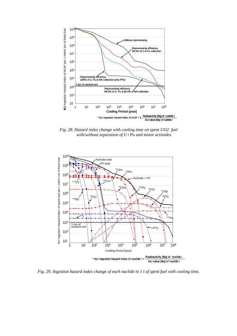
1.00E+01
1.00E+02
1.00E+03
1.00E+04
1.00E+05
1.00E+06
1.00E+07
1.00E+08
1.00E+09
1.00E+10
1.0E+00 1.0E+01 1.0E+02 1.0E+03 1.0E+04 1.0E+05 1.0E+06 1.0E+07 1.0E+081 10 102 103 104 105 106 107 1081.00E+01
1.00E+02
1.00E+03
1.00E+04
1.00E+05
1.00E+06
1.00E+07
1.00E+08
1.00E+09
1.00E+10
1.0E+00 1.0E+01 1.0E+02 1.0E+03 1.0E+04 1.0E+05 1.0E+06 1.0E+07 1.0E+08
1.00E+01
1.00E+02
1.00E+03
1.00E+04
1.00E+05
1.00E+06
1.00E+07
1.00E+08
1.00E+09
1.00E+10
1.0E+00 1.0E+01 1.0E+02 1.0E+03 1.0E+04 1.0E+05 1.0E+06 1.0E+07 1.0E+081 10 102 103 104 105 106 107 10810
102
103
104
105
106
107
108
109
1010
AL
I In
ges
tion
Ha
zard
In
dex
of H
LW*
per
1 m
etric
to
n of
fres
h fu
el
Cooling Period [year]
* ALI Ingestion hazard Index of HLW = ΣRadioactivity [Bq] of nuclide i
ALI value [Bq] of nuclide i
Without reprocessing
Reprocessing efficiency99.5% of U & Pu collection
Reprocessing efficiency99.5% of U, Pu & 99.0% of MA collection
Reprocessing efficiency100% of U, Pu & MA collection (only FPs)
1 ton of uranium ore
10
102
103
104
105
106
107
108
109
1010
AL
I In
ges
tion
Ha
zard
In
dex
of H
LW*
per
1 m
etric
to
n of
fres
h fu
el
10
102
103
104
105
106
107
108
109
1010
AL
I In
ges
tion
Ha
zard
In
dex
of H
LW*
per
1 m
etric
to
n of
fres
h fu
el
Cooling Period [year]
* ALI Ingestion hazard Index of HLW = ΣRadioactivity [Bq] of nuclide i
ALI value [Bq] of nuclide iRadioactivity [Bq] of nuclide i
ALI value [Bq] of nuclide i
Without reprocessing
Reprocessing efficiency99.5% of U & Pu collection
Reprocessing efficiency99.5% of U, Pu & 99.0% of MA collection
Reprocessing efficiency100% of U, Pu & MA collection (only FPs)
1 ton of uranium ore
Fig. 28. Hazard index change with cooling time on spent UO2 fuel with/without separation of U+Pu and minor actinides.
1.00E+01
1.00E+02
1.00E+03
1.00E+04
1.00E+05
1.00E+06
1.00E+07
1.00E+08
1.00E+09
1.00E+10
1.0E+00 1.0E+01 1.0E+02 1.0E+03 1.0E+04 1.0E+05 1.0E+06 1.0E+07 1.0E+081 10 102 103 104 105 106 107 108
10
102
103
104
105
106
107
108
109
1010
AL
I In
ge
stio
n H
aza
rd I
nde
x* o
f sp
en
t fu
el p
er
1 m
etri
c to
n o
f fre
sh f
uel
Cooling Period [year]
* ALI Ingestion hazard Index of nuclide i = Radioactivity [Bq] of nuclide i
ALI value [Bq] of nuclide i
Actinide total
FP total
90Sr
137Cs244Cm
134Cs106Ru
129I
1 ton of uranium ore
241Am239Pu
Actinide + FP
240Pu243Am 229Th 237Np
229Th
231Pa
99Tc
Fig. 29. Ingestion hazard index change of each nuclide in 1 t of spent fuel with cooling time.
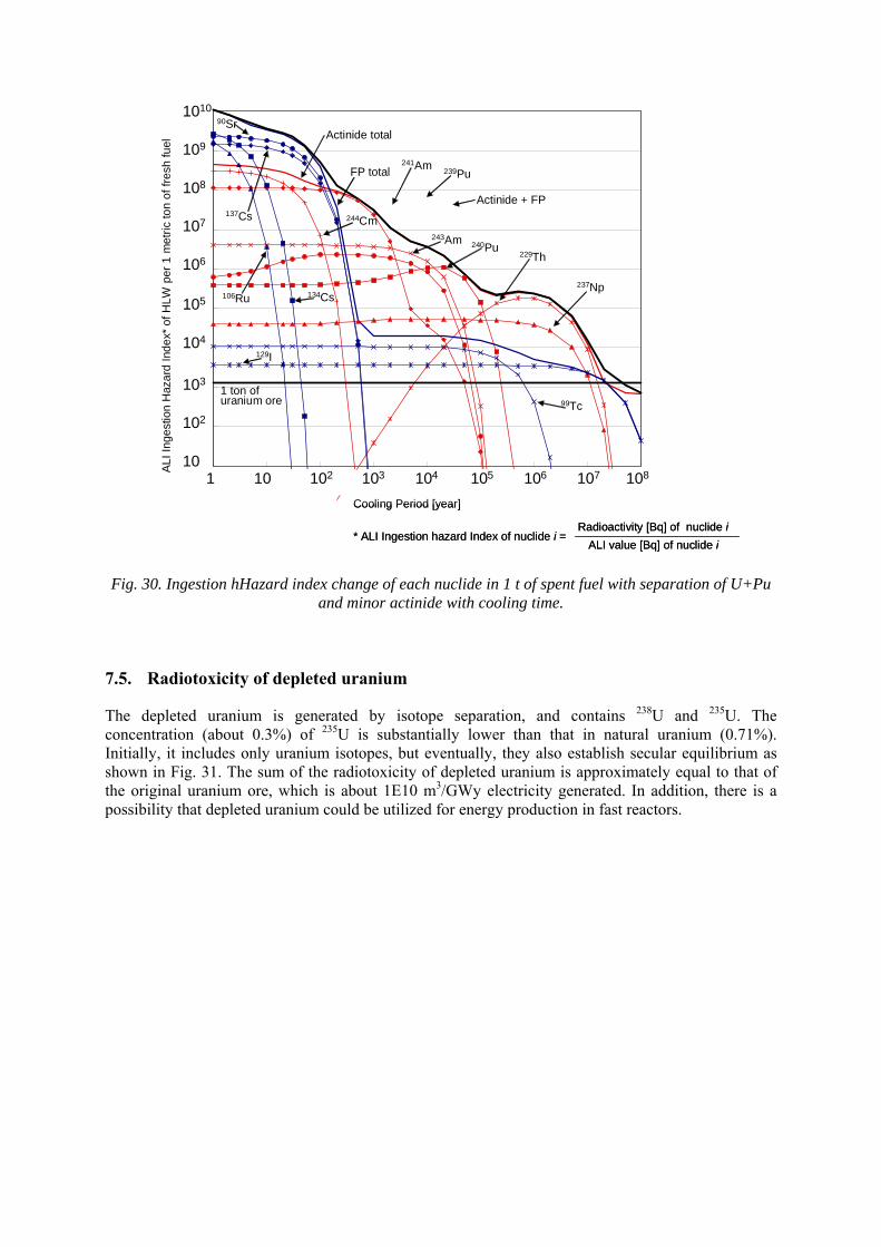
1.00E+01
1.00E+02
1.00E+03
1.00E+04
1.00E+05
1.00E+06
1.00E+07
1.00E+08
1.00E+09
1.00E+10
1.0E+00 1.0E+01 1.0E+02 1.0E+03 1.0E+04 1.0E+05 1.0E+06 1.0E+07 1.0E+081 10 102 103 104 105 106 107 10810
102
103
104
105
106
107
108
109
1010
AL
I In
ge
stio
n H
aza
rd I
nde
x* o
f H
LW
per
1 m
etr
ic to
n o
f fr
esh
fuel
Cooling Period [year]
Actinide total
FP total
90Sr
137Cs 244Cm
134Cs106Ru
129I
1 ton of uranium ore
241Am239Pu
Actinide + FP
240Pu243Am
229Th
237Np
99Tc
* ALI Ingestion hazard Index of nuclide i = Radioactivity [Bq] of nuclide i
ALI value [Bq] of nuclide i
Fig. 30. Ingestion hHazard index change of each nuclide in 1 t of spent fuel with separation of U+Pu and minor actinide with cooling time.
7.5. Radiotoxicity of depleted uranium
The depleted uranium is generated by isotope separation, and contains 238U and 235U. The concentration (about 0.3%) of 235U is substantially lower than that in natural uranium (0.71%). Initially, it includes only uranium isotopes, but eventually, they also establish secular equilibrium as shown in Fig. 31. The sum of the radiotoxicity of depleted uranium is approximately equal to that of the original uranium ore, which is about 1E10 m3/GWy electricity generated. In addition, there is a possibility that depleted uranium could be utilized for energy production in fast reactors.
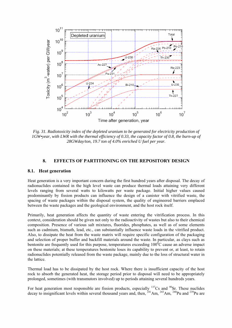
Fig. 31. Radiotoxicity index of the depleted uranium to be generated for electricity production of 1GW•year, with LWR with the thermal efficiency of 0.33, the capacity factor of 0.8, the burn-up of
28GWday/ton, 19.7 ton of 4.0% enriched U fuel per year.
8. EFFECTS OF PARTITIONING ON THE REPOSITORY DESIGN
8.1. Heat generation
Heat generation is a very important concern during the first hundred years after disposal. The decay of radionuclides contained in the high level waste can produce thermal loads attaining very different levels ranging from several watts to kilowatts per waste package. Initial higher values caused predominantly by fission products can influence the design of a canister with vitrified waste, the spacing of waste packages within the disposal system, the quality of engineered barriers emplaced between the waste packages and the geological environment, and the host rock itself.
Primarily, heat generation affects the quantity of waste entering the vitrification process. In this context, consideration should be given not only to the radioactivity of wastes but also to their chemical composition. Presence of various salt mixtures, fluorides, phosphates, as well as of some elements such as cadmium, bismuth, lead, etc., can substantially influence waste loads in the vitrified product. Also, to dissipate the heat from the waste matrix will require specific configuration of the packaging and selection of proper buffer and backfill materials around the waste. In particular, as clays such as bentonite are frequently used for this purpose, temperatures exceeding 1000C cause an adverse impact on these materials; at these temperatures bentonite loses its capability to prevent or, at least, to retain radionuclides potentially released from the waste package, mainly due to the loss of structural water in the lattice.
Thermal load has to be dissipated by the host rock. Where there is insufficient capacity of the host rock to absorb the generated heat, the storage period prior to disposal will need to be appropriately prolonged, sometimes (with transmutors involved) up to periods attaining several hundreds years.
For heat generation most responsible are fission products, especially 137Cs and 90Sr. These nuclides decay to insignificant levels within several thousand years and, then, 241Am, 243Am, 240Pu and 239Pu are
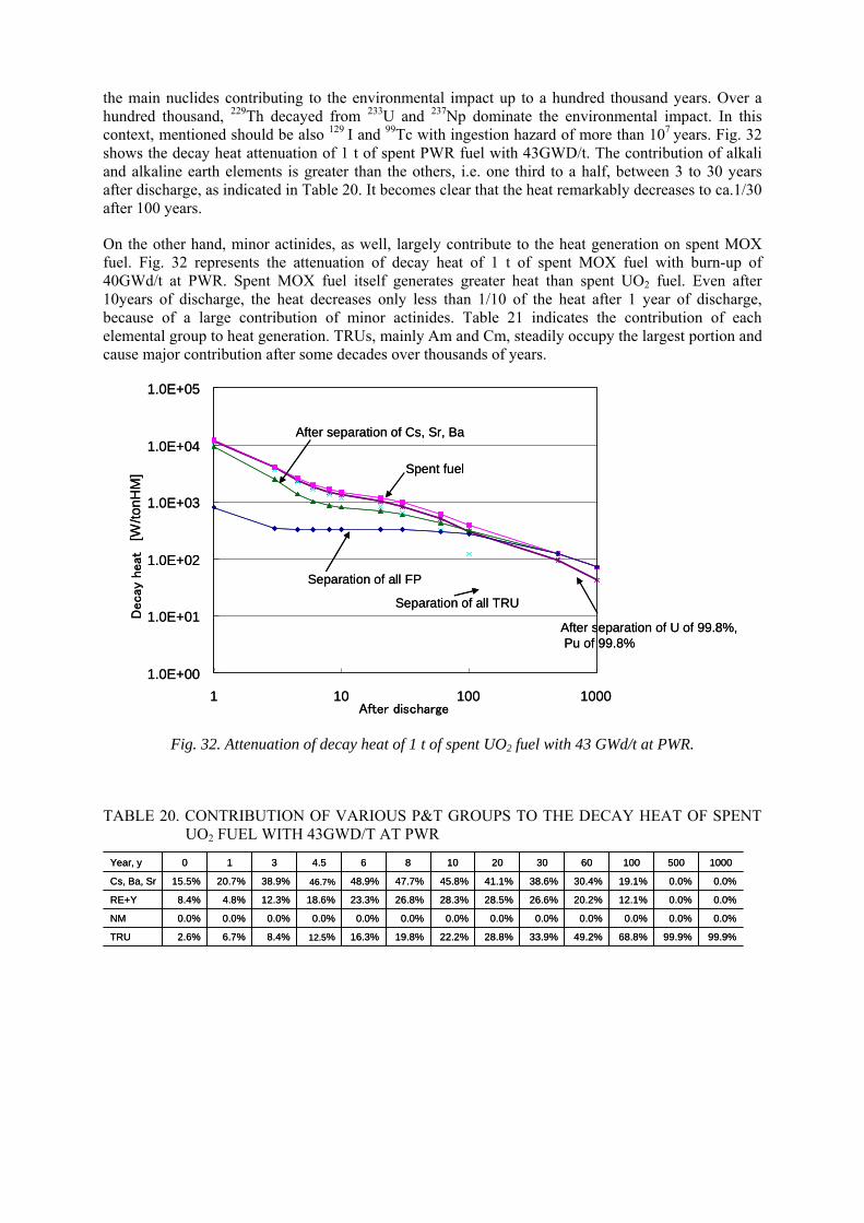
the main nuclides contributing to the environmental impact up to a hundred thousand years. Over a hundred thousand, 229Th decayed from 233U and 237Np dominate the environmental impact. In this context, mentioned should be also 129 I and 99Tc with ingestion hazard of more than 107 years. Fig. 32 shows the decay heat attenuation of 1 t of spent PWR fuel with 43GWD/t. The contribution of alkali and alkaline earth elements is greater than the others, i.e. one third to a half, between 3 to 30 years after discharge, as indicated in Table 20. It becomes clear that the heat remarkably decreases to ca.1/30 after 100 years.
On the other hand, minor actinides, as well, largely contribute to the heat generation on spent MOX fuel. Fig. 32 represents the attenuation of decay heat of 1 t of spent MOX fuel with burn-up of 40GWd/t at PWR. Spent MOX fuel itself generates greater heat than spent UO2 fuel. Even after 10years of discharge, the heat decreases only less than 1/10 of the heat after 1 year of discharge, because of a large contribution of minor actinides. Table 21 indicates the contribution of each elemental group to heat generation. TRUs, mainly Am and Cm, steadily occupy the largest portion and cause major contribution after some decades over thousands of years.
1.0E+00
1.0E+01
1.0E+02
1.0E+03
1.0E+04
1.0E+05
Decay
heat
[W/to
nHM
]
1 10 100 1000After discharge
Spent fuel
Separation of all FP
After separation of Cs, Sr, Ba
After separation of U of 99.8%,Pu of 99.8%
Separation of all TRU
1.0E+00
1.0E+01
1.0E+02
1.0E+03
1.0E+04
1.0E+05
Decay
heat
[W/to
nHM
]
1 10 100 1000After discharge
Spent fuel
Separation of all FP
After separation of Cs, Sr, Ba
After separation of U of 99.8%,Pu of 99.8%
Separation of all TRU
Fig. 32. Attenuation of decay heat of 1 t of spent UO2 fuel with 43 GWd/t at PWR.
TABLE 20. CONTRIBUTION OF VARIOUS P&T GROUPS TO THE DECAY HEAT OF SPENT UO2 FUEL WITH 43GWD/T AT PWR
99.9%99.9%68.8%49.2%33.9%28.8%22.2%19.8%16.3%12.5%8.4%6.7%2.6%TRU
0.0%0.0%0.0%0.0%0.0%0.0%0.0%0.0%0.0%0.0%0.0%0.0%0.0%NM
0.0%0.0%12.1%20.2%26.6%28.5%28.3%26.8%23.3%18.6%12.3%4.8%8.4%RE+Y
0.0%0.0%19.1%30.4%38.6%41.1%45.8%47.7%48.9%46.7%38.9%20.7%15.5%Cs, Ba, Sr
100050010060302010864.5310Year, y
99.9%99.9%68.8%49.2%33.9%28.8%22.2%19.8%16.3%12.5%8.4%6.7%2.6%TRU
0.0%0.0%0.0%0.0%0.0%0.0%0.0%0.0%0.0%0.0%0.0%0.0%0.0%NM
0.0%0.0%12.1%20.2%26.6%28.5%28.3%26.8%23.3%18.6%12.3%4.8%8.4%RE+Y
0.0%0.0%19.1%30.4%38.6%41.1%45.8%47.7%48.9%46.7%38.9%20.7%15.5%Cs, Ba, Sr
100050010060302010864.5310Year, y
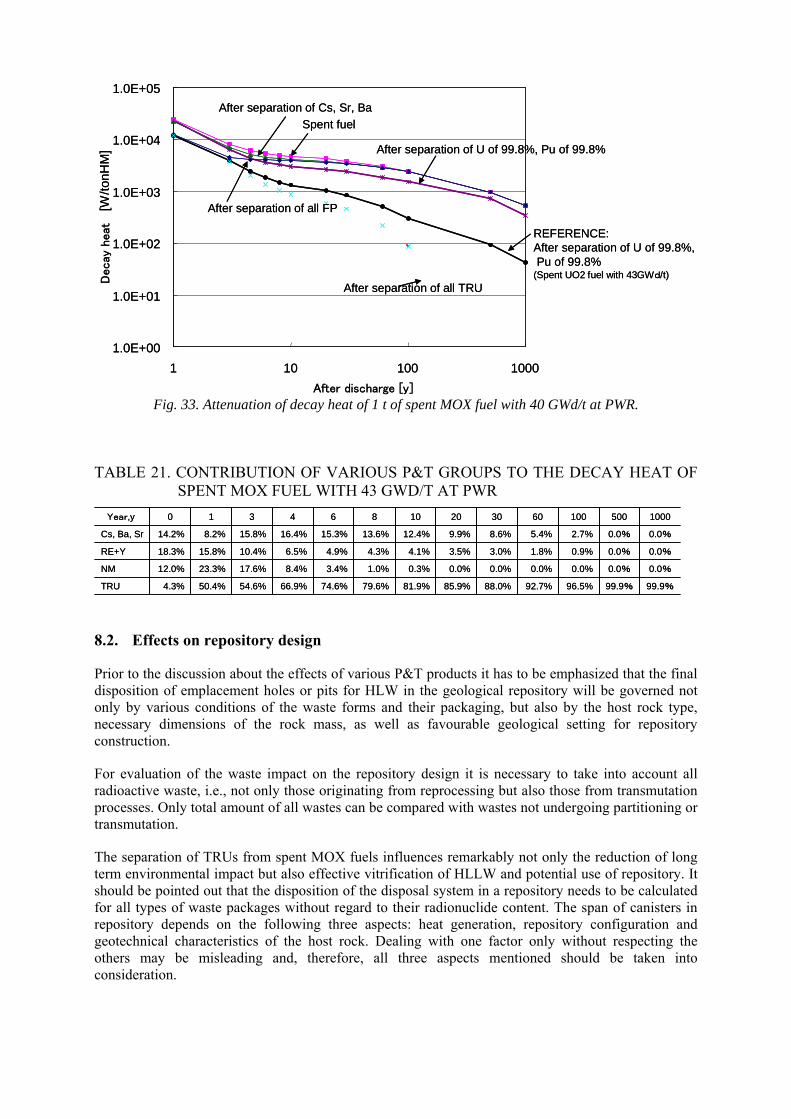
1.0E+00
1.0E+01
1.0E+02
1.0E+03
1.0E+04
1.0E+05D
ecay
heat
[W/to
nHM
]
1 10 100 1000
After discharge [y]
Spent fuel
After separation of all TRU
After separation of all FP
After separation of Cs, Sr, Ba
After separation of U of 99.8%, Pu of 99.8%
REFERENCE:After separation of U of 99.8%,Pu of 99.8%
(Spent UO2 fuel with 43GWd/t)
Fig. 33. Attenuation of decay heat of 1 t of spent MOX fuel with 40 GWd/t at PWR.
TABLE 21. CONTRIBUTION OF VARIOUS P&T GROUPS TO THE DECAY HEAT OF SPENT MOX FUEL WITH 43 GWD/T AT PWR
99.9%99.9%96.5%92.7%88.0%85.9%81.9%79.6%74.6%66.9%54.6%50.4%4.3%TRU
0.0%0.0%0.0%0.0%0.0%0.0%0.3%1.0%3.4%8.4%17.6%23.3%12.0%NM
0.0%0.0%0.9%1.8%3.0%3.5%4.1%4.3%4.9%6.5%10.4%15.8%18.3%RE+Y
0.0%0.0%2.7%5.4%8.6%9.9%12.4%13.6%15.3%16.4%15.8%8.2%14.2%Cs, Ba, Sr
100050010060302010864310Year,y
99.9%99.9%96.5%92.7%88.0%85.9%81.9%79.6%74.6%66.9%54.6%50.4%4.3%TRU
0.0%0.0%0.0%0.0%0.0%0.0%0.3%1.0%3.4%8.4%17.6%23.3%12.0%NM
0.0%0.0%0.9%1.8%3.0%3.5%4.1%4.3%4.9%6.5%10.4%15.8%18.3%RE+Y
0.0%0.0%2.7%5.4%8.6%9.9%12.4%13.6%15.3%16.4%15.8%8.2%14.2%Cs, Ba, Sr
100050010060302010864310Year,y
8.2. Effects on repository design
Prior to the discussion about the effects of various P&T products it has to be emphasized that the final disposition of emplacement holes or pits for HLW in the geological repository will be governed not only by various conditions of the waste forms and their packaging, but also by the host rock type, necessary dimensions of the rock mass, as well as favourable geological setting for repository construction.
For evaluation of the waste impact on the repository design it is necessary to take into account all radioactive waste, i.e., not only those originating from reprocessing but also those from transmutation processes. Only total amount of all wastes can be compared with wastes not undergoing partitioning or transmutation.
The separation of TRUs from spent MOX fuels influences remarkably not only the reduction of long term environmental impact but also effective vitrification of HLLW and potential use of repository. It should be pointed out that the disposition of the disposal system in a repository needs to be calculated for all types of waste packages without regard to their radionuclide content. The span of canisters in repository depends on the following three aspects: heat generation, repository configuration and geotechnical characteristics of the host rock. Dealing with one factor only without respecting the others may be misleading and, therefore, all three aspects mentioned should be taken into consideration.
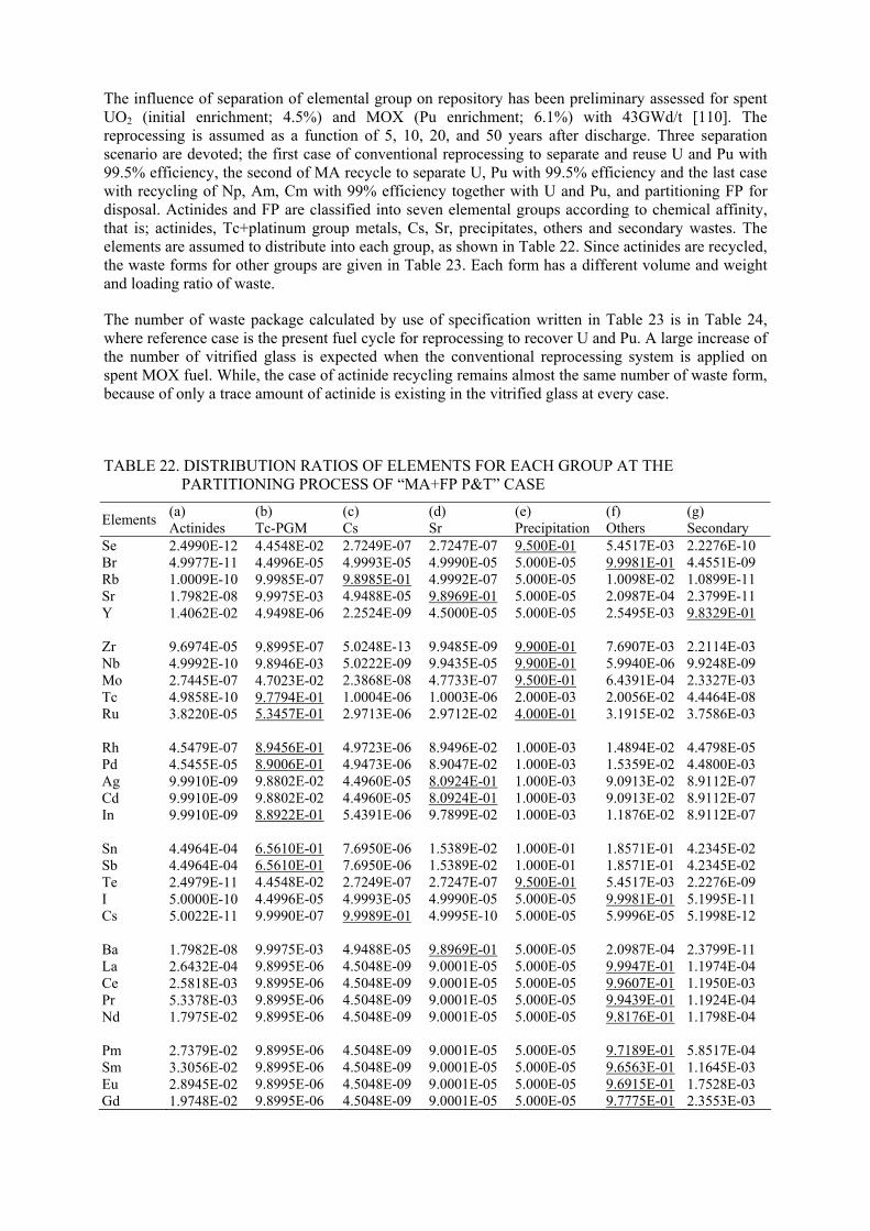
The influence of separation of elemental group on repository has been preliminary assessed for spent UO2 (initial enrichment; 4.5%) and MOX (Pu enrichment; 6.1%) with 43GWd/t [110]. The reprocessing is assumed as a function of 5, 10, 20, and 50 years after discharge. Three separation scenario are devoted; the first case of conventional reprocessing to separate and reuse U and Pu with 99.5% efficiency, the second of MA recycle to separate U, Pu with 99.5% efficiency and the last case with recycling of Np, Am, Cm with 99% efficiency together with U and Pu, and partitioning FP for disposal. Actinides and FP are classified into seven elemental groups according to chemical affinity, that is; actinides, Tc+platinum group metals, Cs, Sr, precipitates, others and secondary wastes. The elements are assumed to distribute into each group, as shown in Table 22. Since actinides are recycled, the waste forms for other groups are given in Table 23. Each form has a different volume and weight and loading ratio of waste.
The number of waste package calculated by use of specification written in Table 23 is in Table 24, where reference case is the present fuel cycle for reprocessing to recover U and Pu. A large increase of the number of vitrified glass is expected when the conventional reprocessing system is applied on spent MOX fuel. While, the case of actinide recycling remains almost the same number of waste form, because of only a trace amount of actinide is existing in the vitrified glass at every case.
TABLE 22. DISTRIBUTION RATIOS OF ELEMENTS FOR EACH GROUP AT THE PARTITIONING PROCESS OF “MA+FP P&T” CASE
Elements (a) Actinides
(b) Tc-PGM
(c) Cs
(d) Sr
(e) Precipitation
(f) Others
(g) Secondary
Se Br Rb Sr Y Zr Nb Mo Tc Ru Rh Pd Ag Cd In Sn Sb Te I Cs Ba La Ce Pr Nd Pm Sm Eu Gd
2.4990E-12 4.9977E-11 1.0009E-10 1.7982E-08 1.4062E-02 9.6974E-05 4.9992E-10 2.7445E-07 4.9858E-10 3.8220E-05 4.5479E-07 4.5455E-05 9.9910E-09 9.9910E-09 9.9910E-09 4.4964E-04 4.4964E-04 2.4979E-11 5.0000E-10 5.0022E-11 1.7982E-08 2.6432E-04 2.5818E-03 5.3378E-03 1.7975E-02 2.7379E-02 3.3056E-02 2.8945E-02 1.9748E-02
4.4548E-02 4.4996E-05 9.9985E-07 9.9975E-03 4.9498E-06 9.8995E-07 9.8946E-03 4.7023E-02 9.7794E-01 5.3457E-01 8.9456E-01 8.9006E-01 9.8802E-02 9.8802E-02 8.8922E-01 6.5610E-01 6.5610E-01 4.4548E-02 4.4996E-05 9.9990E-07 9.9975E-03 9.8995E-06 9.8995E-06 9.8995E-06 9.8995E-06 9.8995E-06 9.8995E-06 9.8995E-06 9.8995E-06
2.7249E-07 4.9993E-05 9.8985E-01 4.9488E-05 2.2524E-09 5.0248E-13 5.0222E-09 2.3868E-08 1.0004E-06 2.9713E-06 4.9723E-06 4.9473E-06 4.4960E-05 4.4960E-05 5.4391E-06 7.6950E-06 7.6950E-06 2.7249E-07 4.9993E-05 9.9989E-01 4.9488E-05 4.5048E-09 4.5048E-09 4.5048E-09 4.5048E-09 4.5048E-09 4.5048E-09 4.5048E-09 4.5048E-09
2.7247E-07 4.9990E-05 4.9992E-07 9.8969E-01 4.5000E-05 9.9485E-09 9.9435E-05 4.7733E-07 1.0003E-06 2.9712E-02 8.9496E-02 8.9047E-02 8.0924E-01 8.0924E-01 9.7899E-02 1.5389E-02 1.5389E-02 2.7247E-07 4.9990E-05 4.9995E-10 9.8969E-01 9.0001E-05 9.0001E-05 9.0001E-05 9.0001E-05 9.0001E-05 9.0001E-05 9.0001E-05 9.0001E-05
9.500E-01 5.000E-05 5.000E-05 5.000E-05 5.000E-05 9.900E-01 9.900E-01 9.500E-01 2.000E-03 4.000E-01 1.000E-03 1.000E-03 1.000E-03 1.000E-03 1.000E-03 1.000E-01 1.000E-01 9.500E-01 5.000E-05 5.000E-05 5.000E-05 5.000E-05 5.000E-05 5.000E-05 5.000E-05 5.000E-05 5.000E-05 5.000E-05 5.000E-05
5.4517E-03 9.9981E-01 1.0098E-02 2.0987E-04 2.5495E-03 7.6907E-03 5.9940E-06 6.4391E-04 2.0056E-02 3.1915E-02 1.4894E-02 1.5359E-02 9.0913E-02 9.0913E-02 1.1876E-02 1.8571E-01 1.8571E-01 5.4517E-03 9.9981E-01 5.9996E-05 2.0987E-04 9.9947E-01 9.9607E-01 9.9439E-01 9.8176E-01 9.7189E-01 9.6563E-01 9.6915E-01 9.7775E-01
2.2276E-10 4.4551E-09 1.0899E-11 2.3799E-11 9.8329E-01 2.2114E-03 9.9248E-09 2.3327E-03 4.4464E-08 3.7586E-03 4.4798E-05 4.4800E-03 8.9112E-07 8.9112E-07 8.9112E-07 4.2345E-02 4.2345E-02 2.2276E-09 5.1995E-11 5.1998E-12 2.3799E-11 1.1974E-04 1.1950E-03 1.1924E-04 1.1798E-04 5.8517E-04 1.1645E-03 1.7528E-03 2.3553E-03
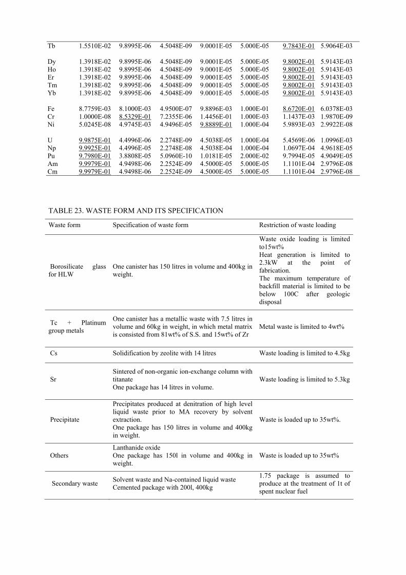
Tb Dy Ho Er Tm Yb Fe Cr Ni U Np Pu Am Cm
1.5510E-02 1.3918E-02 1.3918E-02 1.3918E-02 1.3918E-02 1.3918E-02 8.7759E-03 1.0000E-08 5.0245E-08 9.9875E-01 9.9925E-01 9.7980E-01 9.9979E-01 9.9979E-01
9.8995E-06 9.8995E-06 9.8995E-06 9.8995E-06 9.8995E-06 9.8995E-06 8.1000E-03 8.5329E-01 4.9745E-03 4.4996E-06 4.4996E-05 3.8808E-05 4.9498E-06 4.9498E-06
4.5048E-09 4.5048E-09 4.5048E-09 4.5048E-09 4.5048E-09 4.5048E-09 4.9500E-07 7.2355E-06 4.9496E-05 2.2748E-09 2.2748E-08 5.0960E-10 2.2524E-09 2.2524E-09
9.0001E-05 9.0001E-05 9.0001E-05 9.0001E-05 9.0001E-05 9.0001E-05 9.8896E-03 1.4456E-01 9.8889E-01 4.5038E-05 4.5038E-04 1.0181E-05 4.5000E-05 4.5000E-05
5.000E-05 5.000E-05 5.000E-05 5.000E-05 5.000E-05 5.000E-05 1.000E-01 1.000E-03 1.000E-04 1.000E-04 1.000E-04 2.000E-02 5.000E-05 5.000E-05
9.7843E-01 9.8002E-01 9.8002E-01 9.8002E-01 9.8002E-01 9.8002E-01 8.6720E-01 1.1437E-03 5.9893E-03 5.4569E-06 1.0697E-04 9.7994E-05 1.1101E-04 1.1101E-04
5.9064E-03 5.9143E-03 5.9143E-03 5.9143E-03 5.9143E-03 5.9143E-03 6.0378E-03 1.9870E-09 2.9922E-08 1.0996E-03 4.9618E-05 4.9049E-05 2.9796E-08 2.9796E-08
TABLE 23. WASTE FORM AND ITS SPECIFICATION
Waste form Specification of waste form Restriction of waste loading
Borosilicate glass for HLW
One canister has 150 litres in volume and 400kg in weight.
Waste oxide loading is limited to15wt% Heat generation is limited to 2.3kW at the point of fabrication. The maximum temperature of backfill material is limited to be below 100C after geologic disposal
Tc + Platinum group metals
One canister has a metallic waste with 7.5 litres in volume and 60kg in weight, in which metal matrix is consisted from 81wt% of S.S. and 15wt% of Zr
Metal waste is limited to 4wt%
Cs Solidification by zeolite with 14 litres Waste loading is limited to 4.5kg
Sr Sintered of non-organic ion-exchange column with titanate One package has 14 litres in volume.
Waste loading is limited to 5.3kg
Precipitate
Precipitates produced at denitration of high level liquid waste prior to MA recovery by solvent extraction. One package has 150 litres in volume and 400kg in weight.
Waste is loaded up to 35wt%.
Others Lanthanide oxide One package has 150l in volume and 400kg in weight.
Waste is loaded up to 35wt%
Secondary waste Solvent waste and Na-contained liquid waste Cemented package with 200l, 400kg
1.75 package is assumed to produce at the treatment of 1t of spent nuclear fuel
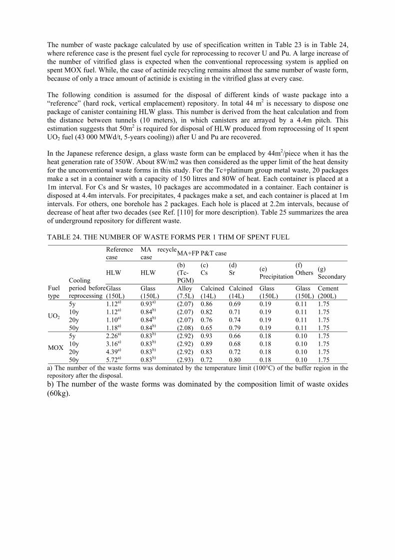
The number of waste package calculated by use of specification written in Table 23 is in Table 24, where reference case is the present fuel cycle for reprocessing to recover U and Pu. A large increase of the number of vitrified glass is expected when the conventional reprocessing system is applied on spent MOX fuel. While, the case of actinide recycling remains almost the same number of waste form, because of only a trace amount of actinide is existing in the vitrified glass at every case.
The following condition is assumed for the disposal of different kinds of waste package into a “reference” (hard rock, vertical emplacement) repository. In total 44 m2 is necessary to dispose one package of canister containing HLW glass. This number is derived from the heat calculation and from the distance between tunnels (10 meters), in which canisters are arrayed by a 4.4m pitch. This estimation suggests that 50m2 is required for disposal of HLW produced from reprocessing of 1t spent UO2 fuel (43 000 MWd/t, 5-years cooling)) after U and Pu are recovered.
In the Japanese reference design, a glass waste form can be emplaced by 44m2/piece when it has the heat generation rate of 350W. About 8W/m2 was then considered as the upper limit of the heat density for the unconventional waste forms in this study. For the Tc+platinum group metal waste, 20 packages make a set in a container with a capacity of 150 litres and 80W of heat. Each container is placed at a 1m interval. For Cs and Sr wastes, 10 packages are accommodated in a container. Each container is disposed at 4.4m intervals. For precipitates, 4 packages make a set, and each container is placed at 1m intervals. For others, one borehole has 2 packages. Each hole is placed at 2.2m intervals, because of decrease of heat after two decades (see Ref. [110] for more description). Table 25 summarizes the area of underground repository for different waste.
TABLE 24. THE NUMBER OF WASTE FORMS PER 1 THM OF SPENT FUEL
Reference case
MA recycle case
MA+FP P&T case
HLW HLW (b) (Tc-PGM)
(c) Cs
(d) Sr
(e) Precipitation
(f) Others
(g) Secondary
Fuel type
Cooling period before reprocessing
Glass (150L)
Glass (150L)
Alloy (7.5L)
Calcined (14L)
Calcined (14L)
Glass (150L)
Glass (150L)
Cement (200L)
5y 1.12a) 0.93a) (2.07) 0.86 0.69 0.19 0.11 1.75 10y 1.12a) 0.84b) (2.07) 0.82 0.71 0.19 0.11 1.75 20y 1.10a) 0.84b) (2.07) 0.76 0.74 0.19 0.11 1.75
UO2
50y 1.18a) 0.84b) (2.08) 0.65 0.79 0.19 0.11 1.75 5y 2.26a) 0.83b) (2.92) 0.93 0.66 0.18 0.10 1.75 10y 3.16a) 0.83b) (2.92) 0.89 0.68 0.18 0.10 1.75 20y 4.39a) 0.83b) (2.92) 0.83 0.72 0.18 0.10 1.75
MOX
50y 5.72a) 0.83b) (2.93) 0.72 0.80 0.18 0.10 1.75 a) The number of the waste forms was dominated by the temperature limit (100°C) of the buffer region in the repository after the disposal. b) The number of the waste forms was dominated by the composition limit of waste oxides (60kg).
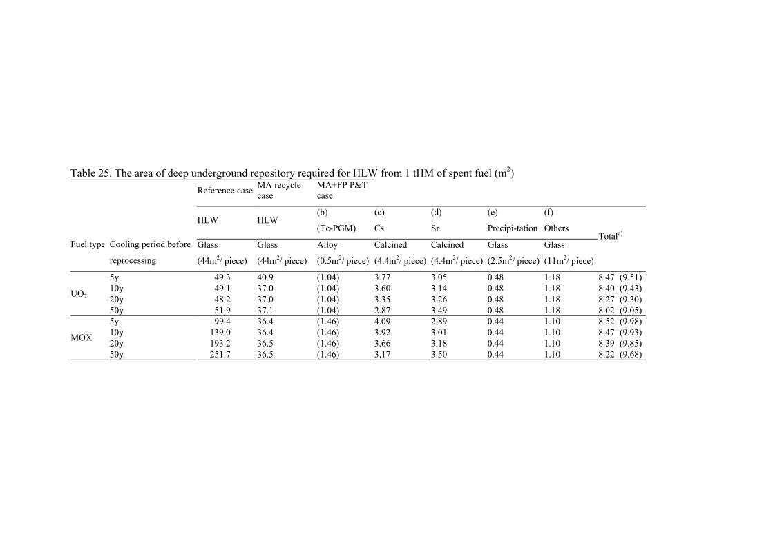
Table 25. The area of deep underground repository required for HLW from 1 tHM of spent fuel (m2)
Reference caseMA recycle case
MA+FP P&T case
HLW HLW (b)
(Tc-PGM)
(c)
Cs
(d)
Sr
(e)
Precipi-tation
(f)
Others
Fuel type
Cooling period before
reprocessing
Glass
(44m2/ piece)
Glass
(44m2/ piece)
Alloy
(0.5m2/ piece)
Calcined
(4.4m2/ piece)
Calcined
(4.4m2/ piece)
Glass
(2.5m2/ piece)
Glass
(11m2/ piece)
Totala)
5y 49.3 40.9 (1.04) 3.77 3.05 0.48 1.18 8.47 (9.51)10y 49.1 37.0 (1.04) 3.60 3.14 0.48 1.18 8.40 (9.43)20y 48.2 37.0 (1.04) 3.35 3.26 0.48 1.18 8.27 (9.30)
UO2
50y 51.9 37.1 (1.04) 2.87 3.49 0.48 1.18 8.02 (9.05)5y 99.4 36.4 (1.46) 4.09 2.89 0.44 1.10 8.52 (9.98)10y 139.0 36.4 (1.46) 3.92 3.01 0.44 1.10 8.47 (9.93)20y 193.2 36.5 (1.46) 3.66 3.18 0.44 1.10 8.39 (9.85)
MOX
50y 251.7 36.5 (1.46) 3.17 3.50 0.44 1.10 8.22 (9.68)
a) Areas in parentheses are including the areas for Tc-PGM group which may be reused or transmuted.The area required for disposal is increasing with cooling period before reprocessing, and the tendency becomes remarkable in case of MOX. Some reduction is expected by recycling minor actinides, and it becomes so effective in case of MOX, depending on the cooling time compared with the area needed for wastes after U and Pu separation. When actinide recycle is realized and group separation is technologically succeeded, the surface area to be necessitated for waste disposal may achieve to the level less than 10 m2. Thus, partitioning and transmutation technology could reduce the dimensions of a waste disposal site and thus, the repository construction and operation costs.
9. DISCUSSION AND RECOMMENDATIONS
9.1. Technological assessment
9.1.1. Aqueous vs. pyro-process
Aqueous processes are represented by the PUREX process installed with a large scale throughput and operated continuously. It is commercially deployed in France, U.K. and Japan for reprocessing of spent oxide fuel from light water reactors. On the other hand, pyro-processes with a batch-wise operation are likely limited up to 100-200t/y of throughput. For minor actinide separation by aqueous processes, effectiveness of specific compounds such as diamide in France, trialkylphosphine oxides in China, carbamoyl methyl phosphine oxide in the U.S. and diisodecylphosporic acid in Japan, have already been verified by use of genuine material, but not yet deployed at a commercial scale.
From the viewpoint of proliferation, the PUREX process is capable of separating readily plutonium with high purity, enabling to supply a weapon-usable material, while a pyro-process provides a material with substantial impurities, such as some amount of lanthanides, except the fluoride volatility process. As regards the waste production, uncertainties of the aqueous processes exist in using organic solvents, which are easily degraded by radiation in case of processing of short cooled and higher TRU content fuels, and in generating large waste volumes due to radiolysis; some organic components can be incinerated, liquids can be evaporated to minimize the volume. Pyro-processes operated mostly at temperatures higher than 500oC have not yet technologically sufficiently matured to estimate the waste generation, spent salt and the dross material of crucible. In view of environmental impacts, pyro-processes seem as causing by one order of magnitude higher hazard than the aqueous processes and two orders of magnitude higher hazard for spent fuel disposal without any reprocessing.
Despite the scarce experience with utilization of pyro-processes on a large scale basis, a preliminary conclusion can be drawn that compared to aqueous processes, the pyro processes seem as more compact, capable of processing with shorter cooling times, and having better radiation resistance. Drawbacks are represented by uncertainties consisting in new waste forms, needs to minimize chemotoxicity, and in making an effort to achieve higher degree of immobilization of produced fission products.
9.1.2. Evaluation of pyro-processes
Several options have been proposed on pyro-processes. Metal electrorefining and oxide electrorefining have a potential to separate uranium and plutonium in a molten chloride media, mainly in LiCl-KCl, or fluoride media, in some case. Minor actinide separation is well foreseen in the metal electrorefining by use of a liquid metal cathode subsequent to uranium recovery onto a solid cathode. Spent oxide fuel can possibly be treated using metal electrorefining after reduction of oxide. The electrochemical reduction is the most promising device for converting oxide into metallic form when compared with chemical reduction during which larger amount of waste is produced. Reductive extraction should be
examined to separate actinides in a spent-salt for minimizing the waste generation. A LiCl-KCl/Cd or /Bi system is a potential method for a counter-current extraction. Electrorefining to obtain uranium and plutonium oxides from spent oxide fuel is operated in a NaCl-CsCl melt, which needs higher temperature operation of 850 C. Pyro-graphite is the most usable material for the electrorefiner.
Electrorefining process utilizes liquid cadmium electrode and operates at high temperatures. This process requires recycle of most of cadmium which is highly toxic and, during the separation becomes contaminated by TRU. Its treatment, conditioning and final disposal represents a serious problem deserving more extensive studies, in particular of the solidification step and of evaluating the behaviour of the final product under deep repository conditions.
Americium is distributed to several streams in the oxide electro-winning process, which needs to explore a preferable separation method. In the waste salt accumulated fission products have to be solidified for disposal, which leads to production of large waste volumes. Fluoride volatilization produces a pure fissile material by use of high volatilization of hexafluoride of uranium and plutonium. In order to avoid the separation of pure plutonium, FLUOREX process has been proposed, in which uranium is separated as uranium hexafluoride and PUREX process is applied to recover the rest of uranium and plutonium. The advantage of this process is minimization of waste volumes resulting from the PUREX process alone. Metal-electrorefining has better potential for recovering minor actinides, while other pyro-processes require an exploration of innovative technique to recover.
9.1.3. Waste forms
Radioactive chloride salt wastes generated from the P&T fuel cycle contain mainly alkali, alkaline-earth, and some of rare-earth fission products and transuranic elements. These wastes must be treated properly to meet the relevant criteria for disposal and the feasibility of solidification needs to be confirmed by performance assessment in disposal conditions. Currently, technical feasibility has been demonstrated only for a glass-bonded sodalite waste form using zeolite A as the waste matrix for chloride salt wastes from the pyro-processes. However, because the waste mass loading is limited to the maximum of 15 percent by mass due to the limitation of the zeolite crystal structure, the resultant mass of solidified wastes is greater than that of original salt wastes.
9.1.4. Repository
Geologic repositories have to provide long term isolation of different waste forms. The potential environmental impacts are primarily influenced by the waste forms and the host rock conditions, which subsequently decide upon the repository design. The results shown in Chapter 7 indicate that the disposal of waste from various separation processes can differently affect the environmental impact. Thus, it is important to select optimal options for effectively minimizing these impacts, in particular, where new waste forms are produced, with different chemical composition, electrochemical and thermodynamic characteristics. It is also necessary to assess impacts of wastes from future utilization of separated materials (e.g. waste from transmutation processes). The current assessment technologies and models are well developed and may be used for such studies.
9.2. Proliferation resistance
From the perspective of proliferation resistance any product of the partitioning processes ought to be of a composition which could not be misused to fabricate directly a nuclear explosive. Under this assumption, processes which separate the actinides individually out of nuclear spent fuel should be disregarded. Remaining are those separation processes, which partition the group of actinides. Presently two of them have emerged: aqueous actinide group extraction and the metal electrorefining process. The first one has the advantage of a continuous process. Taking the vast experience of nuclear material safeguards applied to PUREX reprocessing, one easily could extend this to the aqueous actinide group extraction. On the other side, it has to be seen that this process could be more easily modified to extract a pure, weapon useable actinide than in the pyro-chemical process. The latter one
has - from proliferation point of view - the advantage that there will be separated out always a mix of actinides, still contaminated with rare earth fission products. Such a product constitutes a radiation hazard, not significantly different from spent fuel. Therefore the inherent technological barriers of the pyro-process are higher than for an aqueous one.
In order to minimize the environmental impact of actinides, the discharged actinide inventory has to be reduced to exclude a Pu recovery by future generations. The pyro-waste would have a Pu content lowered by two orders of magnitude. The continuous recycling in the transmutation process further increases the content of other isotopes of Pu viz., 240, 242 and 238, thus making the material even less attractive for future misuse. Since the transmutation will occur in a fast neutron spectrum, the abundance of Np-237 is decreasing considerably compared to LWR waste, which excludes this nuclide from being misused as a nuclear explosive.
The produced actinide mix of the partitioning processes will be diluted by natural or depleted U for reactor fuel production to such an extent that no critical masses can be formed. However, the U diluents might be separated out. This applies for the actinide mix of low U content. Such material exhibits properties that prohibit the use for a nuclear explosive because it will emit enough neutrons by spontaneous fission that a fission chain reaction occurs immediately when a critical mass is reached. If very little fission energy is released, the material will fizzle and the actinide material will be dispersed. Unfortunately, the same or more pronounced effect can be achieved in much more simpler design. The actinide mix can be dispersed by detonation of conventional chemical explosives; in this scenario a contamination with radiotoxic material will occurs, but not nuclear explosion.
9.3. Environmental compliance
9.3.1. Process losses
Minimization of losses of actinides in pyro-processes is essential for reducing not only a process waste with actinides but also uncertainty of the amount of fissile material. An additional process of salt scrubbing is required; however, this may mitigate the economic advantage of the process. The pyro-process is not well cultivated to minimize the process waste in order to achieve more than 99% of recovery efficiency on an engineering scale of deployment, as attained more than 99.5% in the extraction process of the PUREX process. The counter-current reductive extraction has been explored to recover the actinides remaining in the spent salt; in this manner the recovery of 99.5% for each actinide was achieved with a very small scale installation and now verification with a large scale installation has to be examined. Besides the extraction process, chop and leach of the spent fuel will result in the same feature as the PUREX process.
9.3.2. Repository conditions/designs
In geological repository concepts under development in various countries the repository capacity can be expressed in various ways. For example, in the Yucca Mountain Repository (YMR), the statutory limit for capacity is set at 70 000 MTHM of initial fuel materials. In the Japanese repository concept, the capacity is expressed in terms of the number of canisters (40 000 pieces). The repository capacity could be enlarged by expanding the repository footprint, or by reducing the initial mass loading of radionuclides in a waste canister. These technological options together with robust waste packaging are effective in decreasing the release rate of radionuclides from the repository. P&T seems to decrease the inventory of radionuclides in the waste, however, it has be mentioned here that through partitioning various types of liquid wastes will be produced, resulting in different solidification matrices. In this context, optimized solidification processes may solve the problem.
With wider deployment of P&T technology, the increasing amounts of fission products contrary to decreasing actinides can influence, to a certain extent, the repository design. These effects together with new, chemically different waste form will need to be verified by an appropriate performance assessment study.
9.4. Economics of P&T fuel cycle
Similarly to the safety also costs need to be considered in the entire context as a whole, taking into account benefits of the electrical energy produced on the one hand as well as costs of applied technologies including repository costs on the other.
In the case of P&T technology, estimation should be not only investments, i.e. capital and operational costs of individual separation processes, but also costs of treatment, conditioning, packaging and disposal of wastes associated with these processes. Consideration should be also expenses to be spent for decommissioning of facilities (e.g., light water reactors, fast breeders, molten salt reactors, etc). Due to scarce information limited to data about costs from several operational PUREX type reprocessing plants worldwide, and in view of state-of-the-art of developing separation methods, present cost estimates are associated with a number of uncertainties. However, in the future, technological breakthroughs and its application might significantly enhance the economic viability of P&T.
Similar situation is in the area of deep geological disposal. Neither here is conditioning and disposal of high level waste verified on an industrial scale. As regards repository costs, these are mainly based on estimates performed within national programmes developed in some countries. Results of these estimates differ substantially; main factors affecting the final repository costs are of a technical nature, such as the size of the proposed disposal system, geological characteristics of the disposal system, where of a concern is whether the repository is located in a host rock with presence of water, and the engineered barrier system chosen. To these estimates appended are administrative and socio-political issues, which may affect (to a lesser extent) the time schedule of the disposal project, or the siting and licensing process. As a result, repository costs differ from site to site
It can be concluded that an optimum option for implementation of P&T would be a combination and synergistic mix of diverse partitioning methods and transmutation systems. It is perceived that large improvements in partitioning works involving detailed separation scheme would benefit on all other parts of nuclear fuel cycle including repository as well as energy stability with effective natural resources. Hence, future economic assessment should weigh holistic issues considering all other aspects of nuclear energy generation.
9.5. Recommendations
For the reasons outlined, we therefore recommend to continue research and development on advanced fuel cycle approaches that will reduce the proliferation risk and improve nuclear waste management and uranium utilization, without the huge disadvantages of traditional approaches.
9.5.1. Technologies
(1) In order to develop the pyro-process at engineering scale, R&D from several aspects is unavoidable. Some of key equipments have reached to the engineering scale level, like an electrorefiner for uranium recovery, salt waste solidification and a casting device for U-Zr fuel fabrication. However, these equipments have to be even innovated to be a TRU-bearing device with keeping a severe constraint of criticality. Solidified waste form requires to be verified in view of the long term stability and durability at the geologic disposal by use of genuine material. Further efforts should be required to design the equipments of other processes, such as electrochemical reduction cell, reductive extraction device and salt scrubbing column. For a commercial application and semi-continuous operation of the process, a melt transport system of salt and liquid cadmium contributes to achieve an efficient throughput of the unit. Development of the remote handling technology specified on a pyro-process operation in a hot cell is unavoidable. Operation of the most processes is limited in an inert atmosphere, which desires a lower limitation of moisture and oxygen less than 50ppm. Increase of oxygen causes formation of oxides, as represented by dross. Safeguard system should be guaranteed with the fissile material accountancy, in which neptunium and other MA as well as
plutonium should be accounted by allocated key measurement points properly in a material balance area. Design of safeguard and accounting measures are a high priority to apply the pyro-process at a commercial basis.
(2) Aqueous processes can built on the mature technology emerged from PUREX reprocessing. To cope with the danger of fissile material diversion, new processes based on actinide group separation have to be introduced. The extreme low critical mass in moderated systems of Am-242m has to be considered in designing new plants. Present pyro-partitioning methods use molten salts and alloys and are operated at elevated temperatures. The molten salts employed in these methods are, in general, very hygroscopic. The intermediate products in their metallic state are pyrophoric in nature and readily react with the ambient oxygen. Hence high purity inert atmosphere with few ppm of moisture and oxygen becomes inevitable for pyro-processing methods. Realizing such high purity atmosphere inside hot cells is a very big challenge in the design and operation of the plants based on pyro-processing. The fuel itself could be either metallic or ceramic, with the latter not being pyrophoric.
(3) Another decisive parameter for partitioning processes is the process losses. P&T ought to diminish the release of the radio-toxic actinides to the environment. Since the transmutation is not achieved in one cycle, the material has to be recycled, i.e. the accumulated losses of all needed cycles have to be below a given threshold of, e.g., 0.2%. This is a strong challenge for the plant operation; the chemical process itself would achieve this target.
(4) The matrix of the waste form is an essential parameter to guarantee a sustainable exclusion of the radiotoxic materials from being released to the environment. Borosilicate glasses seem to be less stable when compared to the direct storage of spent LWR fuel where the material is exposed to reducing groundwater. Hence, the search for a less leachable waste matrices as well as matrices for new chemical forms of waste (e.g., anthropogenic zeolites for wastes from pyro-reprocessing) is a decisive task to launch a P&T scheme. In this context attention should be paid to minimization of chemotoxic materials; the best way how to achieve this goal is to avoid use these materials in the separation processes and/or to obviate technologies utilizing them
(5) In addition, pyro-partitioning methods are based on batch processes whereas continuous operations like those of the aqueous processes under development are desirable from the point of view of high throughputs. Innovative ways of enabling continuous operation should be thought of also for pyro-processes. In the oxide electrowinning process, the possibility of PuO2 precipitation due to inadvertent increase in the oxygen potential of the ambient is a matter of criticality concern.
(6) High temperature operations necessitate furnaces and other equipment inside hot cells. Operation and maintenance of such equipment is a challenging task. Development of methods and probes for monitoring the levels of molten salt in the process vessels, especially during the transfer between vessels, is desirable but challenging in view of the temperature involved.
(7) Techniques of accounting for nuclear material safeguards and fissile material tracking for criticality control are another area under development.
(8) The inventory of depleted uranium worldwide is large and represents a substantial source of fuel for electricity generation. It is recommended to consider utilization of this material in advanced facilities of higher generation (fast breeder reactors, molten salt reactors, transmutors) not only in view of technology but also of economy.
9.5.2. Synergistic relation between P&T, waste form and repository design
(9) Management of chemotoxic and chemically aggressive materials needs to be also assessed especially calling for attention about metals used as electrodes (cadmium, bismuth) as well as molten salts (chlorides, phosphates) or fluorides serving as separation agent in gaseous form.

(10) Waste from pyro-process contains more corrosive and toxic chlorides, so a fabrication of a high integrity waste form is more limited. Waste form with a high durability and leach-resistance might lighten the cost to meet the disposal criteria. The release of radionuclide from waste form strongly depends on repository condition, such as water-saturated or not. All these variations may have an effect on evaluation of environmental impacts. And more, a reduction of waste generation, which can be achieved by purification and recycle, may promote the usefulness of P&T. Therefore, efforts to fabricate a high-integrity waste form, as well as to reduce the waste generation are essential.
REFERENCES
[1] NUCLEAR ENERGY AGENCY OF THE OECD, Actinide and Fission Product Partitioning and Transmutation, Status and Assessment Report, OECD/NEA, (1999), http://www.nea.fr/html/trw/docs/neastatus99/.
[2] J. MAGILL, et al., “Impact limits of partitioning and transmutation scenarios on the -radiotoxicity of actinides in radioactive waste”, Nuclear Energy, (2003) 42, No. 5, Oct., 263–277.
[3] NUCLEAR ENERGY AGENCY OF THE Organisation for Economic Co-operation and Development (OECD), Accelerator-Driven Systems (ADS) And Fast Reactors (FR) In Advanced Nuclear Fuel Cycles, A Comparative Study, OECD/NEA, (2002).
[4] NUCLEAR ENERGY AGENCY OF THE Organisation for Economic Co-operation and Development (OECD), Advanced Fuel Cycles and Radioactive Waste Management, OECD / NEA, (2006).
[5] INTERNATIONAL ATOMIC ENERGY AGENCY, Implications of Partitioning and Transmutation in Radioactive Waste Management, Technical report Series 435, IAEA (2004).
[6] INTERNATIONAL ATOMIC ENERGY AGENCY, Thorium Fuel Cycle: Potential Benefits and Challenges, IAEA-TECDOC-1450, IAEA, Vienna (2005).
[7] INTERNATIONAL ATOMIC ENERGY AGENCY, Viability of Inert Matrix Fuel In Reducing Plutonium Amounts In Reactor, IAEA-TECDOC-1516, IAEA, Vienna (2006).
[8] TUCEK, K., “Neutronic and Burnup Studies of Accelerator-Driven Systems Dedicated to Nuclear Waste Transmutation”, Doctoral Thesis, Royal Institute of Technology, Stockholm 2004, http://www.neutron.kth.se/publications/library/KamilPhD.pdf
[9] SHROPSHIRE, D. E., et al., “Advanced Fuel Cycle Cost Basis”, INL/EXT-07-12107, U.S. DOE, April 2007.
[10] SVENSK KÄRNBRÄNSLEHANTERING AB, Partitioning and transmutation Current developments – 2007 A report from the Swedish reference group for P&T-research, (Ed.) Per-Eric Ahlström et. al., Technical Report TR-07-04, Svensk Kärnbränslehantering AB, Swedish Nuclear Fuel and Waste Management Co., Sweden (2007) http://www.skb.se/upload/publications/pdf/TR-07-04webb.pdf .
[11] FORSCHUNGSZENTRUM JÜLICH GmBH, RED-IMPACT Impact of Partitioning, -Transmutation and Waste Reduction Technologies on the Final Nuclear Waste Disposal, Synthesis Report, Forschungszentrum Jülich GmBH, Jülich, Germany (2007), ISBN 978-3-89336-538-8.
[12] ORGANIZATION FOR ECONOMIC CO-OPERATION AND DEVELOPMENT/NUCLEAR ENERGY AGENCY, French R&D on the partitioning and Transmutation of Long-lived Radionuclides, NEA No. 6210, OECD/NEA, Paris (2006) ISBN 92-64-02296-1.
[13] SVENSK KÄRNBRÄNSLEHANTERING AB, Partitioning and transmutation, Annual Report 2004, (Ed.) Sofie Andersson, et al., Technical Report R-05-13, Svensk Kärnbränslehantering AB, Swedish Nuclear Fuel and Waste Management Co., Sweden (2004) http://www.skb.se/upload/publications/pdf/R-05-13webb.pdf.
[14] INTERNATIONAL ATOMIC ENERGY AGENCY, Fissile Material Management Strategies for Sustainable Nuclear Energy, Proceedings of a Technical Meeting held in Vienna, 1215 September 2005, IAEA, Vienna (2007).
[15] ORGANIZATION FOR ECONOMIC CO-OPERATION AND DEVELOPMENT/NUCLEAR ENERGY AGENCY, Proc. of Tenth Information Exchange Meeting on Actinide and Fission Product Partitioning and Transmutation, Mito, Japan, 6-10 Oct 2008, OECD/NEA, Paris (2009).
[16] ORGANIZATION FOR ECONOMIC CO-OPERATION AND DEVELOPMENT/NUCLEAR ENERGY AGENCY, Proc. of Actinide and Fission Product Partitioning and Transmutation, Ninth Information Exchange Meeting, Nimes, France, 25-29 September, 2006, NEA 6282, ISBN 978-92-64-99030-2, OECD, Paris (2007).
[17] COMMISSION FOR ATOMIC ENERGY, CEA, Proc. of ATALANTE- 2008: Nuclear Fuel Cycle for a Sustainable Future, Montpellier, France, 19-23 May 2008, CEA, France (2008). {Available from INIS in electronic form INIS-FR--08-1338}.
[18] AMERICAN NUCLEAR SOCIETY, Proc. of GLOBAL 2007 Advanced Nuclear Fuel Cycle Systems, September 9-13, 2007, Boise, USA, American Nuclear Soc., (2007).
[19] WEI, Y-Z., et al., 2006. A Hot Test on Minor Actinides Separation from High-Level-Waste by CMPO/SiO2-P Extraction Resin, Proceedings from Actinides 2005, Manchester July 4–8, (2005) 647–649.
[20] LI, S.X., et al., “Integrated efficiency test for pyrochemical fuel cycles”, Proc. GLOBAL 2007, CD-ROM, Sep. 9-13, 2007, Boise, Idaho, ANS (2007).
[21] INOUE, T. KOYAMA, T. MYOUCIH, M. and ARAI, Y., “Pyroprocessing technology development in Japan”, Proc. GLOBAL 2007, CD-ROM, Sep. 9-13, 2007, Boise, Idaho, U.S.A., ANS (2007).
[22] KORMILITSYN, M.V., BYCHKOV, A.V. ISHUNIN, V.S., “Pyroelectrochemical reprocessing of irradiated fuel of fast reactors. VI. Generalization of experience on BOR-60 spent nuclear fuel reprocessing using approaches “UO2 to UO2” “MOX to PuO2” and “MOX to MOX”, Proc. GLOBAL 2003, CD-ROM, Nov. 16 – 20, 2003, New Orleans, Louisiana, U.S.A.,ANS (2003).
[23] BYCHKOV, A.V., VAVILOV, S.K., PORODNOV, P.T. SKIBA, O.V., “Pyroelectrochemical reprocessing of irradiated uranium-plutonium oxide fuel for fast reactors”, in International Conference and Technology Exposition on Future Nuclear Systems: Emerging Fuel Cycles and Waste Disposal Options, Global' 93, Vol. 2, p. 1351, Seattle, WA, Sept. 12-17, 1993, ANS (1993).
[24] -PLAMBECK, J.A., Fused Salt Systems, Encyclopedia of Electrochemistry of the Elements, Vol X, A. J. Bard, Editor, Marcel Dekker, Inc., N.Y. and Basel (1976).
[25] SAKAMURA, Y., et al., "Measurement of standard potential of actinides (U,Np,Pu,Am) in LiCl-KCl eutectic salt and separation of actinides from rare earths by electrorefining", J. Alloys Comp. 271-273, 592 (1998).
[26] SAKAMURA, Y., SHIRAI, O., IWAI, T. SUZUKI, Y., "Thermodynamics of Neptunium in LiCl-KCl Eutectic / Liquid Bismuth Systems", J. Electrochem. Soc., 147(2), 642 (2000).
[27] SAKAMURA, Y., SHIRAI, O., IWAI, T. and SUZUKI, Y., "Distribution Behavior of Plutonium and Americium in LiCl- KCl Eutectic / Liquid Cadmium Systems", J. Alloys Comp., 321, 76-83 (2001).
[28] SAKAMURA, Y., INOUE, T., STORVICK, T.S. GRANTHAM, L.F., "Development of pyropartitioning process. Separation of transuranium elements from rare earth elements in molten chlorides solution: electrorefining experiments and estimation by using the thermodynamic properties", in International Conference on Evaluation of Emerging Nuclear Fuel Cycle Systems, GLOBAL '95), vol. 2, p. 1185, Versailles, France, Sep. 11-14, (1995).
[29] KINOSHITA, K., et al., “Separation of uranium and transuranics elements from rare earth elements by means of multistage extraction in LiCl-KCl/Bi system”, J. Nucl. Sci. Technol., 36, 2, 189 (1999).
[30] CHANG, Y.I., “The integral fast reactor”, Nuclear Technology, 88, 129 (1989). [31] MCFARLANE, H.F., et al., ‘The IFR fuel cycle demonstration, Progress in Nuclear
Energy, Vol.31, No1/2, pp.155-173, 1997. [32] BENEDICT, R.W., et al., ‘Pyroprocessing progress at Idaho National Laboratory,
Proceedings of GLOBAL 2007, CD-ROM 741, September 9-13, Boise, Idaho, (2007). [33] INOUE, T., et al., ‘Recycling actinides produced in LWR and FBR cycles by applying
pyrometallurgical process, Proceedings of GLOBAL’97, Yokohama, Japan, Oct.5-10, 1997, Vol.1, P.646, (1997).
[34] INOUE, T., et al., ‘Pyroprocessing Technology Development in Japan’, Proc. of GLOBAL2007, CD-ROM 728, September 9-13, Boise, Idaho, (2007).
[35] SAKAMURA, Y., et al., ‘Measurement of standard potentials of actinides (U, Np, Pu, Am) in LiCl-KCl eutectic salt and separation of actinides from rare earths by electrorefining’, J. Alloys and Compounds 271, 592, 1998.
[36] KINOSHITA, K., et al., ‘Separation of actinides from rare earth elements by means of molten salt electrorefining with anodic dissolution of U-Pu-Zr alloy fuel’, J.Phys. and Chem, of Solids, 66 (2005) 619.
[37] IIZUKA, M., et al., ‘Improvement of uranium recovery rate and operational reliability in electrorefining in molten salt with anode/cathode module type electrodes’, In preparation.
[38] KOYAMA, T., et al., ‘Development of Engineering technology basis for industrialization of pyrometallurgical reprocessing’, Proc. of GLOBAL2007, CD-ROM 1038, September 9-13, Boise, Idaho, (2007).
[39] YOU, G-S., et al., ‘Development of an ACP Facility’, Proc. of GLOBAL2007, CD-ROM 1850, September 9-13, Boise, Idaho, (2007).
[40] LACQUEMENT, J., et al., Potentialities of fluoride-based salts for specific nuclear reprocessing: Overview of the R&D program at CEA , Journal of Fluorine Chemistry, Volume 130, Issue 1, (January 2009), Pages 18-21
[41] MALMBECK, R., CASSAYRE, L., MENDES, E., SERP, J., SOECEK, P. GLATZ, J.P., “Recovery of the actinides by electrochemical methods in molten chlorides using solid aluminum cathode”, Proc. GLOBAL 2007, CD-ROM, Sep. 9-13, 2007, Boise, Idaho, U.S.A., (2007).
[42] INOUE, T., et al., Advanced Fuel Cycle with Electrochemical Reduction, Proc. Global 2003, Nov.16-20 (2003) New Orleans, Louisiana.
[43] OMORI, T, et al., “Preliminary examination of electrochemical recovery for high pure UO2”, J48-49, 2005 Fall Meeting of AESJ, CD-ROM, Sep. 13-15, 2007, Hachinohe, Japan (2007) {In Japanese}.
[44] KURATA, M., et al., ‘Electro-chemical reduction of MOX in LiCl’, J. Nucl. Mater. 328 (2004) 97.
[45] SAKAMURA, Y., et al., ‘Electrochemical reduction of UO2 in molten CaCl2 or LiCl’, J. Electrochem. Soc., 153, 3, D31 (2006).
[46] IIZUKA, M., et al., ‘Electrochemical reduction of (U-40Pu-5Np)O2 in molten LiCl electrolyte’, J. Nucl. Mater., 359 (2006) 102.
[47] HAUBENREICH, P.N., Molten-salt reactor progress, Nuclear Engineering International 325 (April 1969) 329.
[48] ROSENTHAL, M.W., HAUBENREICH, P.N., MCCOY, H. E., MCNEESE, L.E., “Chemistry and technology of Molten Salt Reactors – history and perspectives”, Atomic Energy Review, 9 (1971), 601.
[49] JONKE, A.A., Reprocessing of Nuclear Reactor Fuels by Processes Based on Volatilization, Fractional Distillation, and Selective Adsorption, Atomic Energy Review, 3 (1965), 3.
[50] SCHMETS, J.J., “Fluoride volatility method for reprocessing of LWR and FR fuels” Atomic Energy Review, 8(1970), 3.
[51] BENEDICT, M., PIGFORD, T.H., LEVI, H.W., “Nuclear fuel cycle and applied radiochemistry”, Nuclear Chemical Engineering, Second Edition, McGraw-Hill Book Company, New York, (1981), Chapter 6, pp. 310-311.
[52] BOURGEOIS, M., COCHET-MUCHY, B., Application öf the Properties of Fluorides in Nuclear Fuel Cycles”, Bulletin d’Informations Scientific et Techniques, 161(1971), pp. 41-50.
[53] BOURGEOIS, M., Facilities for studying fuel reprocessing using the fluoride volatility process. {Installations pour l'etude du traitement par volatilisation des fluorures des combustibles irradies}, Bulletin d’Informations Scientifiques et Techniques, 188(1974), pp. 7-16 {French}.
[54] DEMJANOWICH, M.A., et al., Fluorination of irradiated uranium-plutonium oxide fuel in flame reactor (in Russian), RIAR report No. 50(565), RIAR, Dimitrovgrad (1982).
[55] NOVY, P., et al., Verification of the Fluoride Reprocessing Technology-Final Report RU 159-113. (in Czech), NRI report No. 9062Ch, (1989), NRI Rez, Czech Republic.
[56] MARECEK, M., NOVY, P., UHLIR, J., “Technological verification of fluoride volatility method for front-end of molten salt transmutation reactor fuel cycle,” In: Proceedings of GLOBAL 2001 – International Conference on Back end of the Fuel Cycle, CEA, Paris, France, (2001).
[57] AMANO, O., et al., “Simulation of Chemical and Electrochemical Behavior of Actinides and Fission Products in Pyrochemical Reprocessing, Proc. of Global (1260-1265) (2003).
[58] SASAHIRA, A., Separation of U and Pu by fluorination JAERI-Conf--2004-011) (2004), {in Japanese}.
[59] AMANO, O., et al., “Verification of Key Technologies for FLUOREX, the New Reprocessing Systém for LWR Fuel Cycle“, In: Proceedings of GLOBAL 2003, ANS, New-Orleans, Louisiana, USA (2003).
[60] YAMASHITA, J., et al., Next-generation nuclear reactor systems for future energy Hitachi Hyoron (Feb 2004) v. 86(2) p. 193-196 {Japanese}.
[61] HOSHINO, K., et al., Proc. of GLOBAL 2005: Ibaraki (Japan) 9-13 Oct 2005. [2562 p.] [5 p.].
[62] SASAHARA, A., et al., “Development of FLUOREX process as progressive LWR reprocessing system”, Proc. GLOBAL 2007, CD-ROM, Sep. 9-13, 2007, Boise, Idaho, U.S.A., (2007).
[63] LEWIS, M.A., et al., “Salt-Occluded Zeolites as an Immobilization Matrix for Chloride Waste Salt”. J. Am. Ceram. Soc., 76, 2826 (1993).
[64] KIM, J.-G., et al., Fabrication of Glass-bonded Zeolite Waste Form for Waste LiCl, J. Ind. Eng. Chem., 13, 292 (2007).
[65] AMERICAN SOCIETY FOR TESTING AND MATERIALS, Product Consistency Test, ASTM C 1285-02 (2002).
[66] EBERT, W.L., "Testing to Evaluate the Suitability of Waste Forms Developed for Electrometallurgically Treated Spent Sodium-Bonded Nuclear Fuel for Disposal in the Yucca Mountain Repository," ANL-05/43, Argonne National Laboratory (2005).
[67] PEREIRA, C., et al., CONF 9604124, “Effects of heating on salt-occluded zeolite” Argonne National Laboratory (1996).
[68] U.S. DEPARTMENT OF ENERGY, Radioactive Waste Management Manual, U.S. DOE M 453.1-1, U.S. DOE, Washington, D.C., 1999.
[69] MCDEAVITT, S.M., et al., Alloy waste forms for metal fission products and actinides isolated by spent nuclear fuel treatment”, ANL/CMT/CP-87845 (1996).
[70] BENEDICT, R.W., et al., Waste forms from the electrometallurgical treatment of DOE spent fuel: Production and general characteristics, in Proc. of Topical conference on plutonium and actinides: Plutonium futures - the science Santa Fe, NM (United States) 10-13 Jul 2000, (2000) v. 532(1) p. 86-88.
[71] MCDEAVITT, S.M., et al., Stainless Steel-Zirconium Waste Forms from the Treatment of Spent Nuclear Fuel JOM 49 (1997) 29-32.
[72] U.S. DEPARTMENT OF ENERGY, “A Report to Congress on Electrometallurgical Treatment Waste Forms”, U.S. DOE, Washington, D.C., (2001).
[73] JANNEY, D.E., “Host phases for actinides in simulated metallic waste forms” J. Nucl. Mater. 323 (2003) 81.
[74] KOYAMA, Shin-ichi, et al., ‘Current Status of PIE Activities in O-arai Engineering Centre of JNC on FBR MOX Fuel’, PIE special session.
[75] BETTI, M., ‘Use of ion chromatography for the determination of fission products and actinides in nuclear applications, J. Chromatography A, 789 (1997) 369–379.
[76] ABOUSAHL, S., et al., Development of Quantitative Analytical Methods for the Control of Actinides in a Pyrochemical Partitioning Process, .Radiochimica Acta, 93 (2005), 147-153.
[77] JARVIS, K.E., et al., Hand book of inductively coupled plasma mass spectrometry, Blackie Academic & Professional, London, (1994).
[78] TRUSCOTT, J.B., et al., ‘Determination of actinide elements at femtogram per gram levels in environmental samples by on-line solid phase extraction and sector-field - inductively coupled plasma-mass spectrometry”, Analytica Chimica Acta 433 (2001) 245–253.
[79] CASSIDY, R.M., et al., ‘Dynamic ion exchange chromatography for the determination of number of fissions in uranium dioxide fuels’, Anal.Chem. (1986) 58, 1181-1186.
[80] SIVARAMAN, N., et al., ‘Burn-up measurements on nuclear reactor fuels using high performance liquid chromatography’, J.Radioanal.Nucl Chem., 2002, 253 (1), 35-40.
[81] IIZUKA, M., “Applicability of electrochemical methods for on-line monitoring of molten salt composition – experimental study with rare earth elements“, Central Research Institute of Electric Power Industry Report T96054, (1997).
[82] IIZUKA, M., et al., Application of normal pulse voltammetry to on-line monitoring of actinide concentrations in molten salt electrolyte, J.Nucl.Mater., 297 (2001) 43.
[83] MC FARLANE, H.M., BENEDICT, R.W., Management of Super-Grade Plutonium in Spent Nuclear Fuel, DOE report ANL/NT/CP/101392, (2000).
[84] SAKAMURA, Y., et al., “Electrochemical reduction of UO2 in molten CaCl2 or LiCl”,7th Int. Sym. Molten Salts Chem. & Technol., Toulouse, France (2005).
[85] U.S. DEPARTMENT OF ENERGY, A Technology Roadmap for Generation IV Nuclear Energy Systems, Nuclear Energy Research Advisory Committee at the Generation IV International Forum, Dec. 2002, GIF-002-00, http://gif.inel.gov, U.S. DOE, Washington, D.C., (2002).
[86] ARGONNE NATIONAL LABORATORY, “A Conceptual Design Study af a Fluoride-Volatility Plant for Reprocessing Lmfbr Fuels”, ANL-7583, Argonne, Ill., (1969).
[87] HOLMES, J.T., STETHERS, H., BARGHUSEN, J.J., “Engineering Development of Fluid-Bed Fluoride Volatility Processes. ANL-7370, Argonne, Ill. (1968).
[88] YUXING, Ye, Proceedings of China-Japan Workshop on Nuclear Management and Fuel Reprocessing, April 5-7, 2000, Beijing, P.R.China (2000).
[89] GALKIN, N.P., et al., Investigation of process of preparation of uranium and plutonium hexafluorides from oxides in application to regeneration of irradiated fuel by fluoride volatility process, {Issledovanie protsessa polucheniya geksaftoridov urana i plutoniya iz okislov primenitel'no k regeneratsii obluchennogo topliva gazoftoridnym metodom} Radiokhimiya (1980). v. 22(5) p. 750-753.(in Russian).
[90] IWASAKI, M., et al., “Fluorination of Plutonium Dioxide by Fluorine”, Journal of Nuclear Science and Technology, Tokyo, Japan (1974).v.11(9). p.403-405.
[91] SHATALOV, V.V., et al., Atomnaya Energiya (Mar 2001) v. 90(3) p. 212-222 (2001) (in Russian).
[92] AMAMOTO, I., “Conceptual Process Flow of a Fluoride Volatility Process under 'Milder' Condition“, GLOBAL 2005: 9-13 (Oct 2005).
[93] AMAMOTO, I., Reprocessing Method by Fluoride Volatility Process Using Fractional Distillation, Patent Application 20060057042 Class: 423019000(Uspto0).
[94] TAKAHASHI, M., et al., Int. Conf. Scientific Research On the Back end of the Fuel Cycle for The 21 Century. Atalante 2000 Avignon (France) 24-26 Oct 2000, Marcoule (France) Scientific Research On The Back end Of The Fuel Cycle For The 21. Century Les Recherches Scientifiques Sur L'aval Du Cycle Pour Le 21. Siecle 2000 [575 P.] P. 1-4 (2000).
[95] BARON, P., et al., An evaluation of the proliferation resistant characteristics of light water reactor fuel with potential for recycle in the United States, Blue-Ribbon report, PNNL, USA (2004).
[96] INTERNATIONAL ATOMIC ENERGY AGENCY, Methodology for the Assessment of Innovative Nuclear Reactors and Fuel Cycles Report of Phase 1B (first part) of the International Project on Innovative Nuclear Reactors and Fuel Cycles (INPRO), IAEA-TECDOC-1434, IAEA, Vienna (2005).
[97] KOCH, L., INOUE, T., YOKOO, T., “A Safer Nuclear Fuel Management Strategy without Sensitive Technology and Weapon Useable Material”, GLOBAL 2005, Oct.10-13, 2005 Tsukuba, Japan (2005).
[98] KOCH, L., “Proliferarion attributes of advanced Pu processing”. Proc. of “Plutonium Future” conference, Dijon (July 2008).
[99] U.S. DEPARTMENT OF ENERGY, Nuclear Material Control and Accountability”, U.S. DOE Manual 470.4-6- U.S. DOE, Washington, D.C., (2006).
[100] BATHKE, C.G., et al., An Assessment of the Proliferation Resistance of Materials in Advanced Nuclear Fuel Cycles, 8.Conf. On Facility Operations- Safeguards Interface, Portland (March 2008).
[101] SEYFRITZ, W., Nukleare Sprengkörper, K.Thiemig Verlag p.54, 1983 (in German). [102] MARKA, J.C., “Explosive Properties of Reactor-Grade Plutonium”, Science & Global
Security, Vol.4 p.111ff (1993). [103] MCKNIGHT, R.D., KRSUL J.R., “Validation results based on the spent fuel
demonstration program at FCF”, ANL Report ANL/RA/CP/10-397, (2000). [104] FORSBERG, C., Long term Criticality Control in Radioactive Waste Disposal Facilities,”
Nuclear Safety, 38, 1, 60, (1997). [105] NATIONAL RESEARCH COUNCIL, “Nuclear Wastes: Technologies for Separation and
Transmutation”, Washington D.C., National Academy Press, (1996). [106] CROFF, A.G., “ORIGEN2: A Versatile Computer Code for Calculating the Nuclide
Compositions and Characteristics of Nuclear Materials,” Nucl. Technoogy, 62, 335 (1983).
[107] AHN, J., CHEON, M., “Linear Programming Approach for Optimization of Radionuclide Loading in Vitrified HLW,” Nucl. Technology., 156, 303 (2006).
[108] AHN, J., Environmental Impact of Yucca Mountain Repository in the Case of Canister Failure, Nuclear Technology, 157, 87-105 (2007).
[109] BOUVIER, E., AHN, J. IKEGAMI, T., “Comparison of Environmental Impacts for PWR-UO2, PWR-MOX and FBR,” Proc. GLOBAL 2007, Advanced Nuclear Fuel Cycles and Systems, Boise, Idaho, Sep. 9-13, 2007, American Nuclear Society (2007) (CD-ROM).
[110] OIGAWA, H., et. al., “Parametric survey on possible impact of partitioning and transmutation of high-level radioactive waste”, Proc. GLOBAL2005, Tsukuba, Japan, Oct.9-13, 2005, Paper No.266 (2005).
ABBREVATIONS
ADS Accelerator driven system
AFC Advanced Fuel Cycle
AHA aceto-hydroxamic acid
ALI Annual Limit of Intake
ALINA Actinide - Lanthanide INtergroup separation in Acidic medium
An actinide(s)
ARTIST Amide-based Radio-resources Treatment with Interim Storage of Transuranics
BAMA process using branched-alkyl monoamides
BSCM bare-sphere critical mass
BTP process based on 2.6-bis(5,6-n-propyl-1,2,4-triazin-3-yl)pyridine)
CANDU Canadian Deuterium-Uranium Reactor
C&S Containment & Surveillance
CCD-PEG process for recovery of Cs and Sr
CMPO octyl(phenyl)-N,N-diisobutyl Carbamoyl Methyl Phosphine Oxide
COEX CO-EXtraction of actinides
CSEX caesium extraction
CSNF commercial spent nuclear fuel
CTH Chalmers Tekniska Hogskola, Sweden
CWF ceramic waste form
CYANEX 301 dialky1dithiophosphinic acid extractant
DF decontamination factor
DFDF DUPIC fuel development facility
DHOA di-n-hexyl-octanamide
DOHA Di Octyl HexanAmide
DIAMEX Diamide Extraction process for extraction of MAs and lanthanides from HLLW
DIDPA Diisodecylphosphoric acid
DOVITA Dry reprocessing, Oxide fuel, Vibro-compact, Integral, and Transmutation of Actinides
DSNC DUPIC Safeguards Neutron Counter
DSNM DUPIC Safeguards Neutron Monitor
DTPA diethylene-triamine-penta-acetic acid
DUPIC Direct Use of spent PWR fuel In CANDU
EBR Experimental Breeder Reactor
EGR Electricity Generation Supported by a 10,000-canister Repository
EIE Peak environmental impact per electricity generation
FBR Fast Breeder Reactor
FCF Fuel Conditioning Facility
FLIBE process using a fluoride salt Li2BeF4
FLUOREX hybrid system that combines fluoride volatilization and solvent extraction methods
FP(s) Fission Product(s)
FR fast reactor
FVM Fluoride Volatility Method
FVP Fluoride volatility process
GANEX Group Actinide Extraction
GNEP Global Nuclear Energy Partnership
HANARO High-flux Advanced Neutron Application Reactor
HDEHP di-2-ethyl-hexyl-phosphoric acid
HLW High Level Waste
HLLW High Level Liquid Waste
HM Heavy Metal
HPLC High Performance Liquid Chromatography
HRGS high-resolution gamma spectrometry
HWR heavy water reactor
ICP-MS inductively coupled plasma mass spectrometry
IC and OC inner core and outer core (indicates configuration of subassemblies in a fast breeder reactor)
IFR Integral Fast Reactor
ICP-MS inductively coupled plasma mass spectrometry
ICT isotope correlation technique
IGCAR Indira Gandhi Centre for Atomic Research, India
IMPUREX Improved PUREX process
ISOZ code for calculation of one dimensional distribution of the nuclides
IST International Safeguards Termination
ITU Institute of Transuranium Elements of the European Commission
KAOS KAERI advanced oxide fuel performance analysis code system
LWR Light Water Reactor
MA (MAs) Minor Actinide(s)
MCC Materials Characterization Center
MPC maximum permissible concentration
MOX Mixed (Uranium-Plutonium) Oxide
MSBR Molten Salt Breeder Reactor
MSR Molten Salt Reactor
MSTR Molten Salt Transmutation Reactor
MT Metric Tonne
MTHM Metric Tonne of Heavy Metal
NCC Neutron Coincidence Counting
NDT Non Destructive Testing
NEXT New EXtraction System for TRU Recovery
NPEX process for recovery of Pu and Np
NRI Nuclear Research Institute, the Czech Republic
NRTA near real-time accountancy
NPT Non-Proliferation Treaty of Nuclear Weapons
OECD/NEA Nuclear Energy Agency of the OECD
OREOX Oxidation and REduction of OXide fuel
P&T Partitioning and Transmutation
PALADIN Partition of Actinides and Lanthanides with Acidic extractant, Diamide and INcinerable’ complexants
PCT Product consistency test
PEI peak environmental impact
PGM Platinum Group Metals
PHWR Pressurized Heavy Water Reactor
PUREX Plutonium and Uranium Recovery by Extraction
PWR Pressurized Water Reactor
RDD radiation dispersion device
RE/AN Rare earths/Actinides
RE(s) rare earth(s)
RP-HPLC Reverse phase high performance liquid chromatography
SANEX Selective ActiNide Extraction
SESAME Selective Extraction and Separation of Americium by Means of Electrolysis
SETFICS Solvent Extraction for Trivalent f-elements Intra-group Separation in CMPO-complexant System
SLZ salt-loaded zeolite
SREX strontium extraction
Super-DIREX Supercritical fluid DIRect EXtraction system
TALSPEAK Trivalent Actinide Lanthanide Separation by Phosphorus Extractants and Aqueous Komplexes
TBP Tri-butyl phosphate
TIMS Thermal Ionization Mass Spectrometry
TMAHDPTZ terdendate N-ligand, 2-(3, 5, 5-trimethylhexanoylamino)- 4, 6-di-(pyridin-2-yl)-1, 3, 5-triazine
TNT Tri-nitro glycerine
TOPO tri-n-octylphosphine oxide
TODGA Tetra-octyl-diglycol-amide
TRPO Trialkylphosphine oxides

TRU Transuranic elements
TRUEX TRU Extraction process from HLLW
TTT Time-Temperature-Transformation
UREX Uranium Extraction (developed in USA)
XRF X ray fluorescence analysis
YMR Yucca Mountain Repository
ANNEX A
DETERMINATION OF LANTHANIDES AND URANIUM
The determination of lanthanides and actinides in low levels is of great importance with respect to nuclear industry and environmental samples. Some of the methods for determination of uranium include radiochemical method, flame atomic absorption, neutron activation analysis, inductively coupled plasma mass spectrometry (ICP-MS) etc. Rapid and accurate determinations of lanthanides have received much attention as industrial demands expand significantly, especially in the field of nuclear sciences and commercial applications.
High performance liquid chromatograph (HPLC) technique using dynamic ion-exchange methods (also referred to as ion-interaction or ion-pair methods) were developed using water soluble modifiers e.g. sodium octane sulfonate for the separation and determination of uranium, and lanthanides. Among the various complexing reagents, α-hydroxy isobutyric acid (α-HIBA) was widely used for the separation of lanthanides and actinides. Detection was generally carried out with post column reaction with a suitable chromogenic reagent, e.g. arsenazo-III or 4-(2-pyridylazo) resorcinol (PAR). HPLC methods were also employed for the determination of uranium from ground waters, separation of uranium from fission products and the determination of number of fissions in burn-up measurements] etc.
Reverse phase high performance liquid chromatograph (RP-HPLC) became powerful technique for separation of uranium from various elements. An XRF-method for the determination of lanthanides such as Sm, Gd, Dy, Er and Eu in uranium solution was investigated. In the absence of internal standard, spectral interferences and matrix effects like absorption enhancement have been taken care by using standards of similar composition.
Inductively Coupled Plasma Mass Spectrometry (ICP-MS) is regarded as a better analytical tool for determination of lanthanides than many conventional techniques for its multi-elemental detection along with high selectivity and sensitivity. Several researchers published a variety of methods for determination of lanthanides in various matrices. The main advantage of ICP-MS is that it enables the analysis of lanthanides without any chemical separation or pre-concentration, though spectroscopic interference from isobaric atomic ions and polyatomic ions like oxides and hydroxides needs attention. An ICP-AES method for the analysis of trace amounts of lanthanides and yttrium in uranium samples and other products generated during the uranium extraction process (hydrometallurgy) from its ores was studied and reported]. Studies were also carried out to develop an HPLC method for the determination of lanthanides, in presence of Th and U, without involving any pre-separation - for the matrix elements like Th and U. Determination of lanthanides and actinides in uranium materials by high-performance liquid chromatography with inductively coupled plasma mass spectrometric detection was also studied.
Uranium and plutonium have been determined in environmental and spent fuel samples, by radiometric techniques such as alpha- and gamma spectrometry and liquid scintillation counting methods. The results, were compared with the one obtained using Inductively Coupled Plasma-Mass Spectrometry (ICP-MS) coupled on-line with ion chromatography, photometry, and laser photometry. Radiometric methods were used for estimating waterborne uranium concentration. Studies showed that laser photometry is an easy and accurate method capable of estimating low uranium concentrations, i.e. ng/mL range. Instrumental neutron activation analysis (INAA), based on nuclear properties of the elements to be determined, is a method of choice in trace analysis of various metal ions including lanthanides.
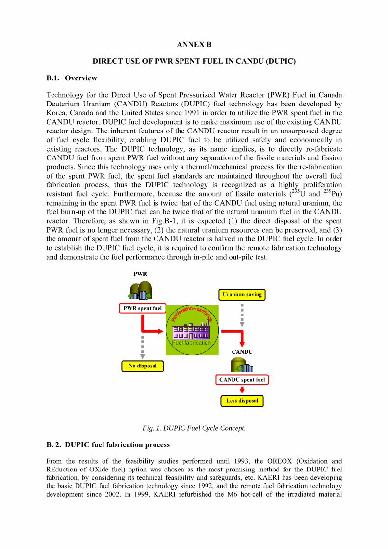
ANNEX B
DIRECT USE OF PWR SPENT FUEL IN CANDU (DUPIC)
B.1. Overview
Technology for the Direct Use of Spent Pressurized Water Reactor (PWR) Fuel in Canada Deuterium Uranium (CANDU) Reactors (DUPIC) fuel technology has been developed by Korea, Canada and the United States since 1991 in order to utilize the PWR spent fuel in the CANDU reactor. DUPIC fuel development is to make maximum use of the existing CANDU reactor design. The inherent features of the CANDU reactor result in an unsurpassed degree of fuel cycle flexibility, enabling DUPIC fuel to be utilized safely and economically in existing reactors. The DUPIC technology, as its name implies, is to directly re-fabricate CANDU fuel from spent PWR fuel without any separation of the fissile materials and fission products. Since this technology uses only a thermal/mechanical process for the re-fabrication of the spent PWR fuel, the spent fuel standards are maintained throughout the overall fuel fabrication process, thus the DUPIC technology is recognized as a highly proliferation resistant fuel cycle. Furthermore, because the amount of fissile materials (235U and 239Pu) remaining in the spent PWR fuel is twice that of the CANDU fuel using natural uranium, the fuel burn-up of the DUPIC fuel can be twice that of the natural uranium fuel in the CANDU reactor. Therefore, as shown in Fig.B-1, it is expected (1) the direct disposal of the spent PWR fuel is no longer necessary, (2) the natural uranium resources can be preserved, and (3) the amount of spent fuel from the CANDU reactor is halved in the DUPIC fuel cycle. In order to establish the DUPIC fuel cycle, it is required to confirm the remote fabrication technology and demonstrate the fuel performance through in-pile and out-pile test.
PWR
Uranium saving
No disposal
Less disposal
CANDU
PWR spent fuel
CANDU spent fuel
Fuel fabrication
PWR
Uranium saving
No disposal
Less disposal
CANDU
PWR spent fuel
CANDU spent fuel
Fuel fabrication
Fig. 1. DUPIC Fuel Cycle Concept.
B. 2. DUPIC fuel fabrication process
From the results of the feasibility studies performed until 1993, the OREOX (Oxidation and REduction of OXide fuel) option was chosen as the most promising method for the DUPIC fuel fabrication, by considering its technical feasibility and safeguards, etc. KAERI has been developing the basic DUPIC fuel fabrication technology since 1992, and the remote fuel fabrication technology development since 2002. In 1999, KAERI refurbished the M6 hot-cell of the irradiated material
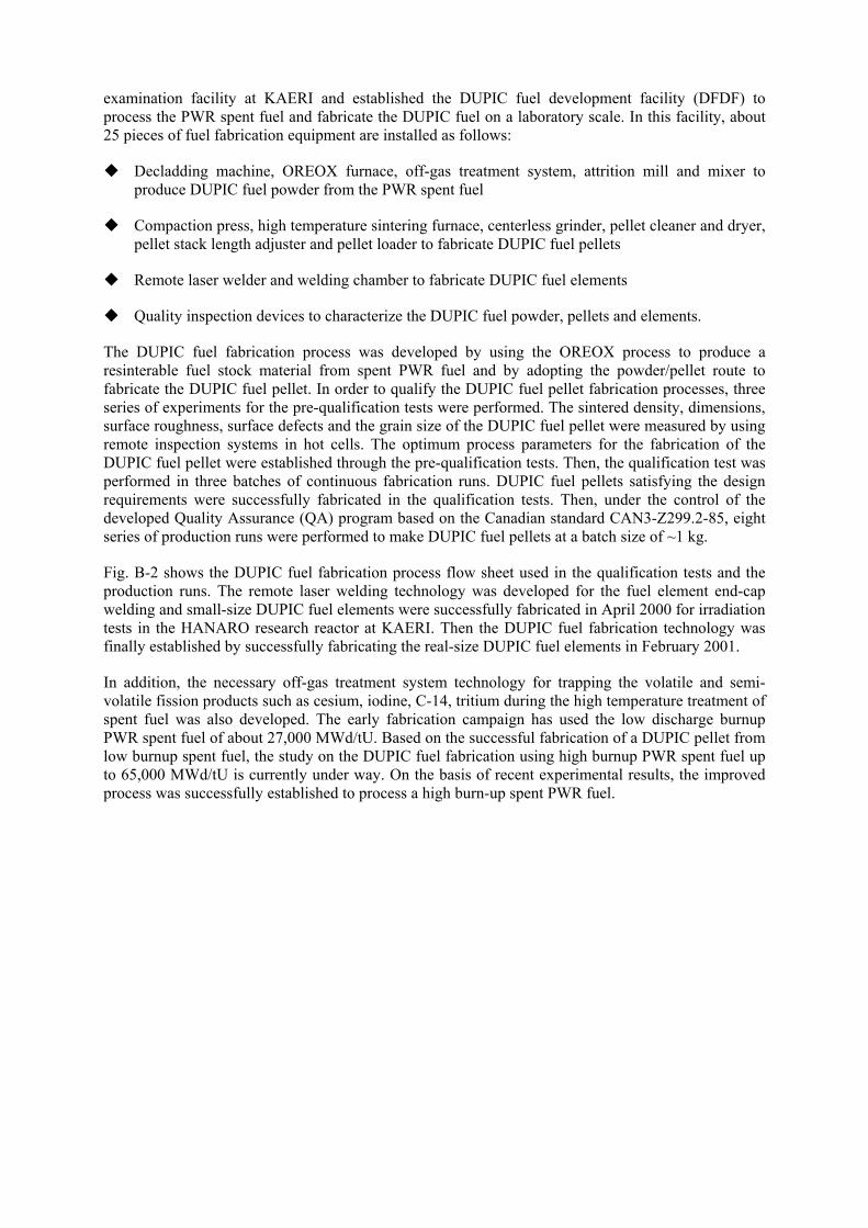
examination facility at KAERI and established the DUPIC fuel development facility (DFDF) to process the PWR spent fuel and fabricate the DUPIC fuel on a laboratory scale. In this facility, about 25 pieces of fuel fabrication equipment are installed as follows:
Decladding machine, OREOX furnace, off-gas treatment system, attrition mill and mixer to produce DUPIC fuel powder from the PWR spent fuel
Compaction press, high temperature sintering furnace, centerless grinder, pellet cleaner and dryer, pellet stack length adjuster and pellet loader to fabricate DUPIC fuel pellets
Remote laser welder and welding chamber to fabricate DUPIC fuel elements
Quality inspection devices to characterize the DUPIC fuel powder, pellets and elements.
The DUPIC fuel fabrication process was developed by using the OREOX process to produce a resinterable fuel stock material from spent PWR fuel and by adopting the powder/pellet route to fabricate the DUPIC fuel pellet. In order to qualify the DUPIC fuel pellet fabrication processes, three series of experiments for the pre-qualification tests were performed. The sintered density, dimensions, surface roughness, surface defects and the grain size of the DUPIC fuel pellet were measured by using remote inspection systems in hot cells. The optimum process parameters for the fabrication of the DUPIC fuel pellet were established through the pre-qualification tests. Then, the qualification test was performed in three batches of continuous fabrication runs. DUPIC fuel pellets satisfying the design requirements were successfully fabricated in the qualification tests. Then, under the control of the developed Quality Assurance (QA) program based on the Canadian standard CAN3-Z299.2-85, eight series of production runs were performed to make DUPIC fuel pellets at a batch size of ~1 kg.
Fig. B-2 shows the DUPIC fuel fabrication process flow sheet used in the qualification tests and the production runs. The remote laser welding technology was developed for the fuel element end-cap welding and small-size DUPIC fuel elements were successfully fabricated in April 2000 for irradiation tests in the HANARO research reactor at KAERI. Then the DUPIC fuel fabrication technology was finally established by successfully fabricating the real-size DUPIC fuel elements in February 2001.
In addition, the necessary off-gas treatment system technology for trapping the volatile and semi-volatile fission products such as cesium, iodine, C-14, tritium during the high temperature treatment of spent fuel was also developed. The early fabrication campaign has used the low discharge burnup PWR spent fuel of about 27,000 MWd/tU. Based on the successful fabrication of a DUPIC pellet from low burnup spent fuel, the study on the DUPIC fuel fabrication using high burnup PWR spent fuel up to 65,000 MWd/tU is currently under way. On the basis of recent experimental results, the improved process was successfully established to process a high burn-up spent PWR fuel.
OxidationReduction
Milling
Composition
Sintering
Dry Grinding
DUPIC Pellet
Stack-lengthLoading
EndcapWelding
Element QC
DUPIC Element
Clean ElementPackage/Ship
Surface DefectsDimensionSurface Roughness
Pellet QC
Stack Length
He Leak TestMicrostructureDimensionVisual Inspection
Recycling
Spent PWR Fuel
Disassembling
Cutting
SlittingDecladding
S/G-NDAto DFDF
Oxidation
Blending
Raw PowderS/G-NDA (homogeneity)
CompositionDensityMicrostructure
Pellet QC
Granulation
Mixing
Compaction
Precompaction
Dewaxing
Density
Green density
Incominginspection of hardware
Mixing
OxidationReduction
MillingMilling
Composition
Sintering
Dry Grinding
DUPIC Pellet
Stack-lengthLoading
EndcapWelding
Element QC
DUPIC Element
Clean ElementPackage/Ship
Surface DefectsDimensionSurface Roughness
Pellet QC
Stack Length
He Leak TestMicrostructureDimensionVisual Inspection
Recycling
Spent PWR Fuel
Disassembling
Cutting
SlittingDecladding
S/G-NDAto DFDF
Oxidation
Blending
Raw PowderS/G-NDA (homogeneity)
CompositionDensityMicrostructure
Pellet QC
Granulation
Mixing
Compaction
Precompaction
Dewaxing
Density
Green density
Granulation
Mixing
Compaction
Precompaction
Dewaxing
Density
Green density
Incominginspection of hardware
MixingMixing
Fig. 2. DUPIC fuel fabrication flow sheet.
B. 3. DUPIC fuel performance assessment
As the DUPIC fuel fabrication technology is developed, the performance analysis and irradiation tests of the DUPIC fuel have been carried out at a full momentum since 1998. The DUPIC fuel performance has been assessed in the following three areas: (1) Thermal and mechanical material properties of the DUPIC fuel pellet, (2) Performance analysis code development for the DUPIC fuel, and (3) Irradiation test and post-irradiation examination. Based on database of DUPIC fuel pellet material properties, the material characteristics models of the DUPIC fuel have been developed to construct the performance analysis code system. The Young’s modulus, hardness, fracture toughness and the diffusion coefficient were measured together with the DUPIC fuel, while others were obtained from the open literature.
The KAERI advanced oxide fuel performance analysis code system (KAOS) has been developed to construct the DUPIC fuel performance analysis code system and to perform the safety analysis of the DUPIC fuel irradiation tests in the HANARO research reactor. The KAOS code system has two major functions: the first one is to analyze a macroscopic fuel behaviour during an irradiation in a reactor and the second one is to assess a fuel integrity in the reactor using a commercially-available finite element method. In addition, the ELESTRES-D code was developed for the analysis of the DUPIC fuel behaviour in a CANDU reactor by combining the existing fuel analysis code ELESTRES and the DUPIC fuel pellet material properties obtained in this study, which established the fuel performance analysis system for the licensing and practical use of the DUPIC fuel.
A total of six DUPIC fuel irradiation tests have been carried out in HANARO from 1999 to 2006. The first, second and fourth tests were non-instrumented tests, while the third one was an instrumented test to measure the thermal neutron flux of the irradiation hole and the fifth one was an instrumented test to on-line measure the center temperature of the DUPIC fuel pellet. One fuel element irradiated in the third test was burned again in the fourth test. This element has a fuel burnup of 6700 MWd/tHM,
which is the highest among all the fuel burn/ups obtained until now. The maximal and average linear element ratings of this element were estimated to be 34 kW/m and 25 kW/m, respectively.
The comparison of the pellet centerline temperature between the on-line measurement (1st instrumented irradiation test of the highly radioactive fuel in Korea) and the KAOS calculation showed that the calculation result was a little conservative for the 1st cycle of the irradiation but matched the measurement result within 8% for the temperature range of 800~1200℃. Currently the KAOS can predict the fuel behavior only for the normal condition. The post-irradiation examination was performed for the DUPIC fuel pellet which was irradiated to the average fuel burn/up of the standard CANDU fuel. The irradiation behavior of the DUPIC fuel is not that different from that of the standard CANDU spent fuel or PWR spent fuel of 40 000 MWd/tHM.
B.4. Compatibility with CANDU reactor
The DUPIC fuel should be designed such that the CANDU reactor operates without compromising the safety and economics of the system. Therefore the compatibility can be assessed by considering the general design requirements as follows:
1) The fuel design, reactor operation and reactor safety parameters should not exceed the design limits during normal and transient conditions.
2) The total and local power levels should be controlled safely. It should be possible to trip the reactor and maintain a subcriticality if necessary.
3) Two independent shutdown systems are required and each system should possess the capability of maintaining a subcriticality.
4) The reactor control and safety system should not hurt the economics and flexibility of the CANDU reactor.
Considering these design requirements, the compatibility of the DUPIC fuel with the CANDU reactor was assessed for the fuel lattice physics characteristics, reactor power distribution, reactivity devices performance and the operational margin.
B.5. Nuclear material safeguards
The DUPIC Safeguards Neutron Counter (DSNC) and DUPIC Safeguards Neutron Monitor (DSNM) have been developed and used in the DFDF where the nuclear material is handled in a laboratory scale. The DSNC is a non-destructive neutron counting system for the verification of the nuclear material flow during the DUPIC process, which estimates the plutonium content of the nuclear material based on the quantitative measurement of the 244Cm content even in the high gamma radiation environment. The DSNC together with the DSNM has been approved by the IAEA as the official nuclear material measurement and monitoring devices of the DFDF and used for IAEA and national inspections.
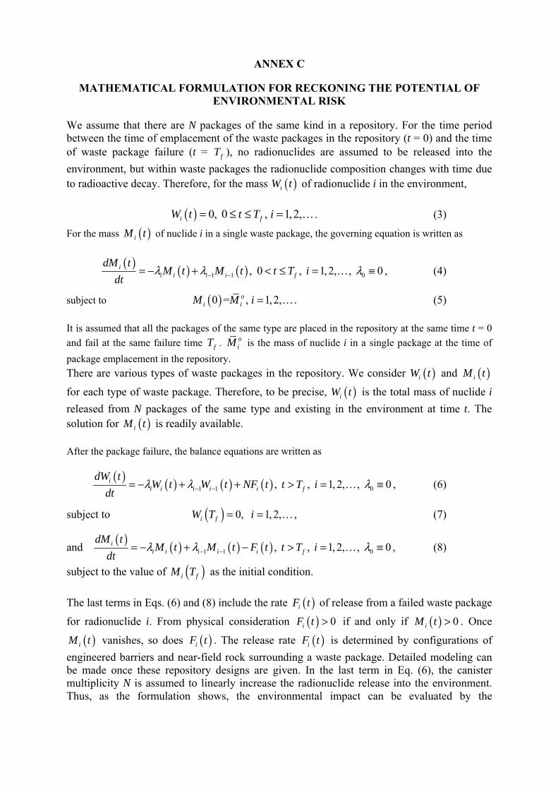
ANNEX C
MATHEMATICAL FORMULATION FOR RECKONING THE POTENTIAL OF ENVIRONMENTAL RISK
We assume that there are N packages of the same kind in a repository. For the time period between the time of emplacement of the waste packages in the repository (t = 0) and the time of waste package failure (t = fT ), no radionuclides are assumed to be released into the
environment, but within waste packages the radionuclide composition changes with time due to radioactive decay. Therefore, for the mass ( )iW t of radionuclide i in the environment,
( ) 0, 0 , 1,2,i fW t t T i= ≤ ≤ = . (3)
For the mass ( )iM t of nuclide i in a single waste package, the governing equation is written as
( ) ( ) ( )1 1 0, 0 , 1, 2, , 0ii i i i f
dM tM t M t t T i
dtλ λ λ− −= − + < ≤ = ≡ , (4)
subject to ( )0 = , 1, 2,oi iM M i = . (5)
It is assumed that all the packages of the same type are placed in the repository at the same time t = 0
and fail at the same failure time fT . oiM is the mass of nuclide i in a single package at the time of
package emplacement in the repository.
There are various types of waste packages in the repository. We consider ( )iW t and ( )iM t
for each type of waste package. Therefore, to be precise, ( )iW t is the total mass of nuclide i
released from N packages of the same type and existing in the environment at time t. The solution for ( )iM t is readily available.
After the package failure, the balance equations are written as
( ) ( ) ( ) ( )1 1 0, , 1, 2, , 0ii i i i i f
dW tW t W t NF t t T i
dtλ λ λ− −= − + + > = ≡ , (6)
subject to ( ) 0, 1, 2,i fW T i= = , (7)
and ( ) ( ) ( ) ( )1 1 0, , 1, 2, , 0ii i i i i f
dM tM t M t F t t T i
dtλ λ λ− −= − + − > = ≡ , (8)
subject to the value of ( )i fM T as the initial condition.
The last terms in Eqs. (6) and (8) include the rate ( )iF t of release from a failed waste package
for radionuclide i. From physical consideration ( ) 0iF t > if and only if ( ) 0iM t > . Once
( )iM t vanishes, so does ( )iF t . The release rate ( )iF t is determined by configurations of
engineered barriers and near-field rock surrounding a waste package. Detailed modeling can be made once these repository designs are given. In the last term in Eq. (6), the canister multiplicity N is assumed to linearly increase the radionuclide release into the environment. Thus, as the formulation shows, the environmental impact can be evaluated by the

composition in the waste package oiM , the engineered-barrier configuration that determine
( )iF t , and the number of packages.
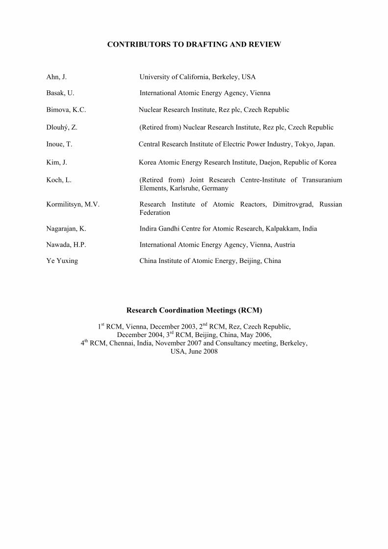
CONTRIBUTORS TO DRAFTING AND REVIEW
Ahn, J. University of California, Berkeley, USA
Basak, U. International Atomic Energy Agency, Vienna
Bimova, K.C. Nuclear Research Institute, Rez plc, Czech Republic Dlouhý, Z. (Retired from) Nuclear Research Institute, Rez plc, Czech Republic
Inoue, T. Central Research Institute of Electric Power Industry, Tokyo, Japan. Kim, J. Korea Atomic Energy Research Institute, Daejon, Republic of Korea Koch, L. (Retired from) Joint Research Centre-Institute of Transuranium
Elements, Karlsruhe, Germany
Kormilitsyn, M.V. Research Institute of Atomic Reactors, Dimitrovgrad, Russian Federation
Nagarajan, K. Indira Gandhi Centre for Atomic Research, Kalpakkam, India
Nawada, H.P. International Atomic Energy Agency, Vienna, Austria
Ye Yuxing China Institute of Atomic Energy, Beijing, China
Research Coordination Meetings (RCM)
1st RCM, Vienna, December 2003, 2nd RCM, Rez, Czech Republic, December 2004, 3rd RCM, Beijing, China, May 2006,
4th RCM, Chennai, India, November 2007 and Consultancy meeting, Berkeley, USA, June 2008