Embed Size (px)
Citation preview
Automated Absolute Field Calibration of GPS Antennas in Real-Time1
Gerhard Wübbena, Martin Schmitz Geo++, Gesellschaft für satellitengestützte geodätische und navigatorische Technologien mbH
D-30827 Garbsen, Germany
Falko Menge, Volker Böder, Günter Seeber Institut für Erdmessung, Universität Hannover
D-30167 Hannover, Germany
1 Presented at ION GPS 2000, 19-22 September, Salt Lake City, Utah, USA
BIOGRAPHY Dr. Günter Seeber has been Professor at the Institut für Erdmessung, Universität Hannover since 1973, where he teaches satellite geodesy, geodetic astronomy and marine geodesy. He has specialized in satellite positioning techniques since 1969 and has published several scientific papers and books in the field of satellite and marine geodesy. Falko Menge and Volker Böder received their Dipl.-Ing. in Geodesy from the Universität Hannover and are currently employed as research associates in satellite positioning at the Institut für Erdmessung. Their current project concern the GPS antenna and multipath calibration. Dr. Gerhard Wübbena received his degrees in Geodesy from the Universität Hannover. He has worked in the field of GPS since 1983 and developed the program system GEONAP. In 1990 he founded the company Geo++, which develops satellite navigation and positioning software and systems. Dr. Martin Schmitz also received his degrees in Geodesy from the Universität Hannover. Present projects are i.e. active reference networks for
highly precise RTK positioning (GNSMART) and the GPS station calibration project. ABSTRACT A procedure for the absolute field calibration of GPS-antennas has already been presented earlier by this group with encouraging results. Further developments have now led to an automated procedure based on the precisely controlled motion of a calibrated robot. The field calibration includes new features and provides results in real-time. The new concept is based on GPS field observations in several thousand different antenna orientations (rotations, tilts), and eliminates the multipath influences. Due to these features, also azimuthal phase center variations can be determined with reliability and high resolution. The results are also valid for very low elevations down to zero degrees. Experiences demonstrate large azimuthal PCV variations for some antenna types. The reliability of the results for an individual antenna is confirmed through multiple calibrations at different sites, with different robots and different observation schedules. The absolute calibration results are used in various applications (small engineering networks, large networks,
etc.) and show the advantages and the need for precise absolute PCV information. INTRODUCTION The two dominant station dependent error terms are phase center variations (PCV) of the receiving antenna and multipath (MP), which are of great concern for precise GPS positioning applications. Different procedures are currently carried out and investigated by several working groups in order to estimate corrections for either PCV or MP separately or also commonly from in-situ calibrations. Since both PCV and MP are different and independent error components, the aim of our group is to strictly separate between the two error sources. The paper only deals with the absolute field procedure for the estimation of PCV. Still, one has to take care of MP effects in the calibration procedure in order to obtain station independent corrections, which can be used wherever they are needed. The direct determination of precise MP phase corrections from GPS observations is an important and still evolving object of research (e.g. Ray 2000, Wanninger and May 2000, Mora-Castro et al. 1998), carried out also by our group. The separation of MP and PCV is a pre-requisite for their precise description. There exist static and time-variant errors on a station. MP can be considered as a time-dependent error source, since variations in the environment (e.g. reflecting surfaces) can be influencing factors. One can assume static behavior for the PCV of an antenna while disregarding factors like temperature dependencies and ageing. Still, it is always important to calibrate a whole antenna system for a proper characterization of the used unit. Thus, the results describe the inherent PCV of the receiving antenna element together with near-field impacts from e.g. groundplanes and dome constructions. The experience of our group is, that changes in larger distances to the antenna do not have an influence on the antenna PCV.
Figure 1: PCV description of a GPS antenna A full description of the phase behavior of a GPS antenna contains information on the antenna reference point (ARP), the north direction, values for both frequencies for a 3D mean phase center (offset) referring to the ARP, and finally the PCV for L1 and L2 affiliated to the given
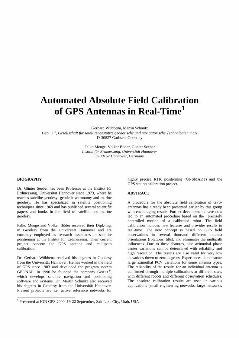
offsets. The relationship of these values are shown in figure 1. Details can be found in several publications, e.g. in Rothacher et al. (1995), Menge and Seeber (2000), Menge et al. (2000). It is important to notice, that PCV must always refer to an identical reference point while comparing different PCV sets. PCV can be transformed to another reference, for example from a mean phase center to another offset or to the ARP. Some GPS users only consider a correction for a mean offset. Since it is widely known and described (Rothacher et al. 1995, UNAVCO 1995, Wübbena et al. 1997, Mader 1999, Menge and Seeber 2000) that the offset is only a mean correction and approximation for the PCV, this correction is not recommended for highly precise applications. Beside the fact, that neglecting PCV corrections can lead to height errors of several cm while estimating tropospheric parameters, also the offset-only determination is variable and not consistent (see also figure 2). Offsets are dependent of the used observations, therefore a function of the elevation mask, location, satellite constellation and observation time. They can be relative to another antenna or absolute or even mixed. Finally, the minimum condition for the adjustment can be different. The offsets can be estimated directly from the phase measurements or from the PCV.
Figure 2: Offset problematic
The most common used PCV corrections are estimated in relative field calibrations (e.g. Mader 1999). Within this rather uncomplicated field calibration, the PCV are estimated relative to a given reference antenna. The PCV of the reference antenna are set to zero and their offsets are fixed to a certain value. Due to remaining MP influence, it is difficult to estimate azimuthal PCV or even PCV below 10 deg elevation. The results are not sufficient for differently orientated antennas (e.g. rotated/inclined antennas and large networks). The second group of PCV calibrations are absolute. Measurements in anechoic chambers (Schupler 1994, Schupler et al. 1995) use artificial signals. The experimental requirements are high, and there are also remaining difficulties, e.g. precise determination of reference point, precision of the whole mechanical set-up, possible remaining MP effects, reaching a high number of different positions and the use of an artificial signal. The absolute field calibration (Wübbena et al. 1997, Menge et al. 1998) uses the observations of a rotated and inclined GPS antenna. More details will be described in the next paragraph.
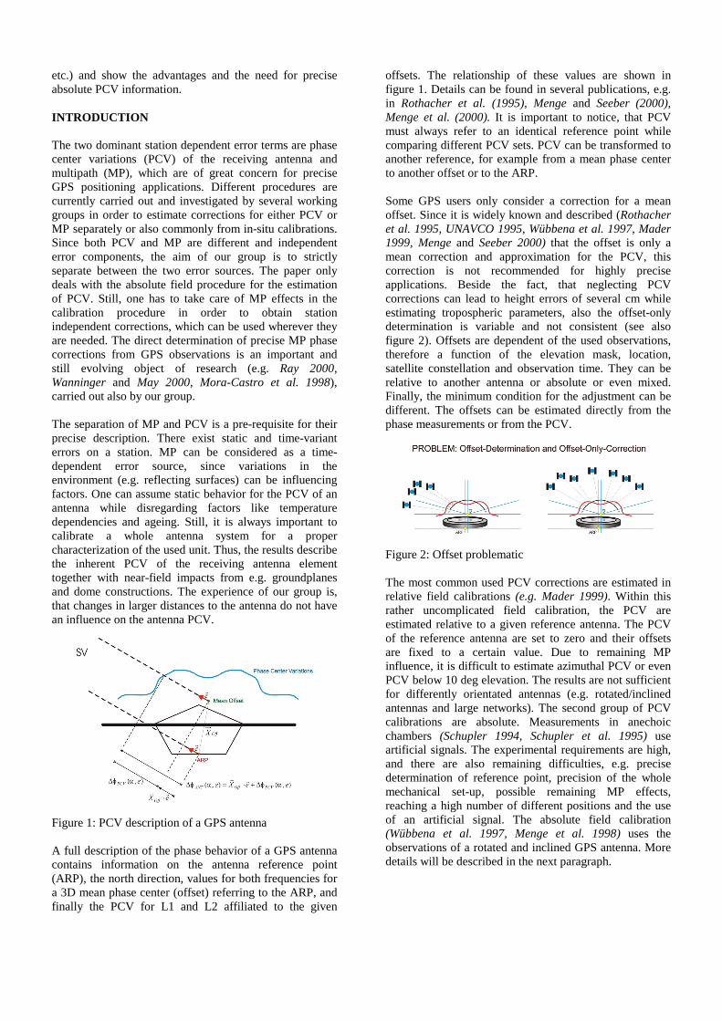
REAL-TIME CALIBRATION – DEVELOPMENT AND FEATURES The development of an absolute field calibration was based on deficiencies of the available calibration procedures at that time. Relative calibrations always refer to a reference antenna and the results are correlated with the station. The absolute chamber measurements have some disadvantages or unresolved features (see last paragraph). Therefore, the goal was to separate MP and PCV and to obtain absolute PCV independent from a reference antenna and the involved station. The realization mainly bases on the use of a differently orientated antenna and the use of special observation differences. The development started with a precise handmade antenna mount and finally led to an automatic precise robot (figure 3). The primary task of mount or robot is to rotate the antenna around a fixed point (i.e. nominal phase center). The first procedure was a post-processing calibration using siderial day time differences. Improvements within the absolute field calibration procedure (precision of the antenna mount, differential MP differences, observation and manual processing efforts) then led to the automated real-time procedure using a calibrated robot.
Figure 3: Robot In the siderial day time difference, the MP error term removes (in fact greatly reduces) due to identical MP conditions on two measurement days. The PCV difference between the zero position on the reference day and the rotated/tilted orientation on the second day serves as input for the PCV determination using spherical harmonics. All other parameters are removed or estimated. Details can be found in Wübbena et al. (1997), Seeber et al. (1998) and Menge et al. (1998). The undifferenced observation equation is the basis for the real-time calibration procedure. In addition to the standard modeling procedure on short baselines, multipath parameters are estimated as stochastic processes, using the
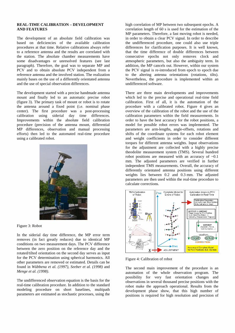
high correlation of MP between two subsequent epochs. A correlation length of 60 s is used for the estimation of the MP parameters. Therefore, a fast moving robot is needed, in order to obtain a clear PCV signal. In order to describe the undifferenced procedure, one could also use triple differences for clarification purposes. It is well known, that the time difference of double differences between consecutive epochs not only removes clock and atmospheric parameters, but also the ambiguity term. In addition, the MP cancels out. However, within our system the PCV signal is re-introduced from epoch to epoch due to the altering antenna orientations (rotations, tilts). Nevertheless, the procedure is implemented within an undifferenced software. There are three main developments and improvements which led to the precise and operational real-time field calibration. First of all, it is the automation of the procedure with a calibrated robot. Figure 4 gives an overview of the calibration of the robot and the use of the calibration parameters within the field measurements. In order to have the best accuracy for the robot positions, a model for possible robot errors was implemented. The parameters are arm-lengths, angle-offsets, rotations and shifts of the coordinate systems for each robot element and weight coefficients in order to consider different torques for different antenna weights. Input observations for the adjustment are collected with a highly precise theodolite measurement system (TMS). Several hundred robot positions are measured with an accuracy of ~0.1 mm. The adjusted parameters are verified in further independent TMS measurements. Overall, the accuracy of differently orientated antenna positions using different weights lies between 0.2 and 0.3 mm. The adjusted parameters are then used within the real-time procedure to calculate corrections.
Figure 4: Calibration of robot The second main improvement of the procedure is an automation of the whole observation program. The possibility for very fast orientation changes and observations in several thousand precise positions with the robot make the approach operational. Results from the development phase show, that this high number of positions is required for high resolution and precision of
the derived PCV. Even azimuthal PCV can be reliably and precisely estimated (also see next paragraph).
80
60
40
20
0
20
40
60
80
Observations on Antenna Hemisphere - RT Calibration (on MSD7)
"RT_Calib.azel"
80
60
40
20
0
20
40
60
80
Observations on Antenna Hemisphere - 24h Static (on MSD7)
"24h_Static.azel"
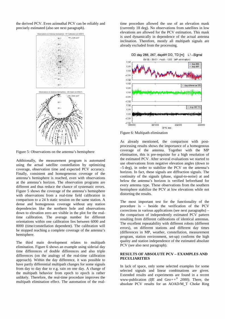
Figure 5: Observations on the antenna’s hemisphere
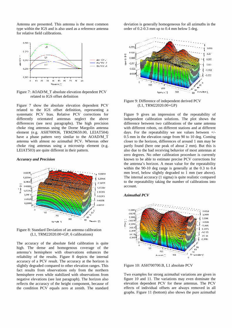
Additionally, the measurement program is automated using the actual satellite constellation by optimizing coverage, observation time and expected PCV accuracy. Finally, consistent and homogeneous coverage of the antenna’s hemisphere is reached, even with observations at the antenna’s horizon. The observation programs are different and thus reduce the chance of systematic errors. Figure 5 shows the coverage of the antenna’s hemisphere with observations from a real-time field calibration in comparison to a 24 h static session on the same station. A dense and homogenous coverage without any station dependencies like the northern hole and observations down to elevation zero are visible in the plot for the real-time calibration. The average number for different orientations within one calibration lies between 6000 and 8000 (time/constellation dependent). The calibration will be stopped reaching a complete coverage of the antenna’s hemisphere. The third main development relates to multipath elimination. Figure 6 shows an example using siderial day time differences of double differences and also triple differences (on the analogy of the real-time calibration approach). Within the day difference, it was possible to have partly differential multipath changes for some signals from day to day due to e.g. rain on one day. A change of the multipath behavior from epoch to epoch is rather unlikely. Therefore, the real-time procedure improves the multipath elimination effect. The automation of the real-
time procedure allowed the use of an elevation mask (currently 18 deg). No observations from satellites in low elevations are allowed for the PCV estimation. This mask is used dynamically in dependence of the actual antenna inclination. Therefore, mostly all multipath signals are already excluded from the processing.
Figure 6: Multipath elimination As already mentioned, the comparison with post-processing results shows the importance of a homogenous coverage of the antenna. Together with the MP elimination, this is pre-requisite for a high resolution of the estimated PCV. After several evaluations we started to use observations from negative elevation angles (down to –5 deg), in order to stabilize the PCV on the antenna’s horizon. In fact, these signals are diffraction signals. The continuity of the signals (phase, signal-to-noise) at and below the antenna’s horizon is verified beforehand for every antenna type. These observations from the southern hemisphere stabilize the PCV at low elevations while not distorting the results. The most important test for the functionality of the procedure is – beside the verification of the PCV corrections in various applications (see next paragraphs) – the comparison of independently estimated PCV pattern resulting from different calibrations of identical antennas. The excellent repeatability with different robots (different errors), on different stations and different day times (differences in MP, weather, constellation, measurement program, station environment, set-up) confirms the high quality and station independence of the estimated absolute PCV (see also next paragraph). RESULTS OF ABSOLUTE PCV – EXAMPLES AND PECULIARITIES In lack of space, only some selected examples for some selected signals and linear combinations are given. Extended results and experiments are found in a recent www-publication (IfE and Geo++ 2000). There, the absolute PCV results for an AOAD/M_T Choke Ring
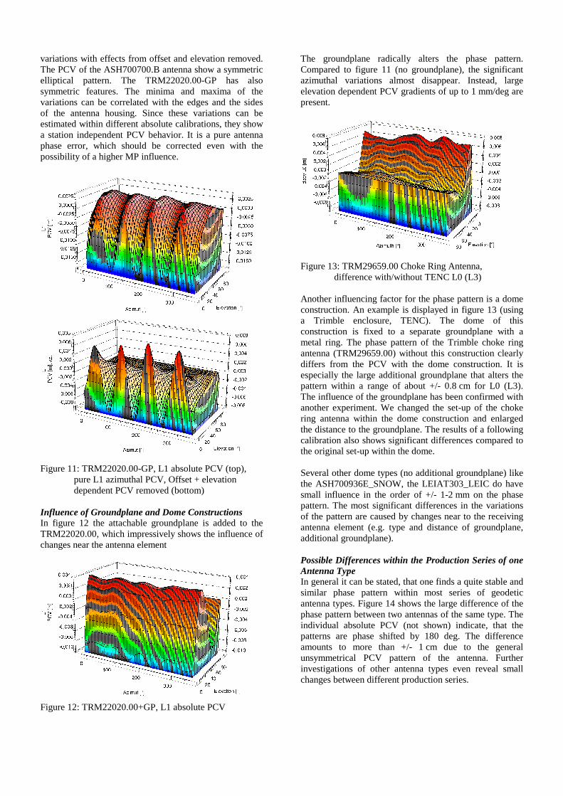
Antenna are presented. This antenna is the most common type within the IGS and is also used as a reference antenna for relative field calibrations.
Figure 7: AOAD/M_T absolute elevation dependent PCV related to IGS offset definition Figure 7 show the absolute elevation dependent PCV related to the IGS offset definition, representing a systematic PCV bias. Relative PCV corrections for differently orientated antennas neglect the above differences (see next paragraphs). The high precision choke ring antennas using the Dorne Margolin antenna element (e.g. ASH700936, TRM29659.00, LEIAT504) have a phase pattern very similar to the AOAD/M_T antenna with almost no azimuthal PCV. Whereas other choke ring antennas using a microstrip element (e.g. LEIAT503) are quite different in their pattern. Accuracy and Precision
Figure 8: Standard Deviation of an antenna calibration
(L1, TRM22020.00+GP, 6 calibrations)
The accuracy of the absolute field calibration is quite high. The dense and homogenous coverage of the antenna’s hemisphere with observations enhances the reliability of the results. Figure 8 depicts the internal accuracy of a PCV result. The accuracy at the horizon is slightly degraded compared to other elevation ranges. This fact results from observations only from the northern hemisphere even while stabilized with observations from negative elevations (see last paragraph). The horizon also reflects the accuracy of the height component, because of the condition PCV equals zero at zenith. The standard
deviation is generally homogeneous for all azimuths in the order of 0.2-0.3 mm up to 0.4 mm below 5 deg.
Figure 9: Difference of independent derived PCV (L1, TRM22020.00+GP) Figure 9 gives an impression of the repeatability of independent calibration solutions. The plot shows the difference between two calibrations of the same antenna with different robots, on different stations and at different days. For the repeatability we see values between +/- 0.5 mm in the elevation range from 90 to 10 deg. Coming closer to the horizon, differences of around 1 mm may be partly found (here one peak of about 2 mm). But this is also due to the bad receiving behavior of most antennas at zero degrees. No other calibration procedure is currently known to be able to estimate precise PCV corrections for the antenna’s horizon. A mean value for the repeatability within the 90-10 deg range is generally at the 0.3 to 0.4 mm level, below slightly degraded to 1 mm (see above). The internal accuracy (1 sigma) is quite realistic compared to the repeatability taking the number of calibrations into account. Azimuthal PCV
Figure 10: ASH700700.B, L1 absolute PCV Two examples for strong azimuthal variations are given in figure 10 and 11. The variations may even dominate the elevation dependent PCV for these antennas. The PCV effects of individual offsets are always removed in all graphs. Figure 11 (bottom) also shows the pure azimuthal
variations with effects from offset and elevation removed. The PCV of the ASH700700.B antenna show a symmetric elliptical pattern. The TRM22020.00-GP has also symmetric features. The minima and maxima of the variations can be correlated with the edges and the sides of the antenna housing. Since these variations can be estimated within different absolute calibrations, they show a station independent PCV behavior. It is a pure antenna phase error, which should be corrected even with the possibility of a higher MP influence.
Figure 11: TRM22020.00-GP, L1 absolute PCV (top), pure L1 azimuthal PCV, Offset + elevation
dependent PCV removed (bottom) Influence of Groundplane and Dome Constructions In figure 12 the attachable groundplane is added to the TRM22020.00, which impressively shows the influence of changes near the antenna element
Figure 12: TRM22020.00+GP, L1 absolute PCV
The groundplane radically alters the phase pattern. Compared to figure 11 (no groundplane), the significant azimuthal variations almost disappear. Instead, large elevation dependent PCV gradients of up to 1 mm/deg are present.
Figure 13: TRM29659.00 Choke Ring Antenna,
difference with/without TENC L0 (L3) Another influencing factor for the phase pattern is a dome construction. An example is displayed in figure 13 (using a Trimble enclosure, TENC). The dome of this construction is fixed to a separate groundplane with a metal ring. The phase pattern of the Trimble choke ring antenna (TRM29659.00) without this construction clearly differs from the PCV with the dome construction. It is especially the large additional groundplane that alters the pattern within a range of about +/- 0.8 cm for L0 (L3). The influence of the groundplane has been confirmed with another experiment. We changed the set-up of the choke ring antenna within the dome construction and enlarged the distance to the groundplane. The results of a following calibration also shows significant differences compared to the original set-up within the dome. Several other dome types (no additional groundplane) like the ASH700936E_SNOW, the LEIAT303_LEIC do have small influence in the order of +/- 1-2 mm on the phase pattern. The most significant differences in the variations of the pattern are caused by changes near to the receiving antenna element (e.g. type and distance of groundplane, additional groundplane). Possible Differences within the Production Series of one Antenna Type In general it can be stated, that one finds a quite stable and similar phase pattern within most series of geodetic antenna types. Figure 14 shows the large difference of the phase pattern between two antennas of the same type. The individual absolute PCV (not shown) indicate, that the patterns are phase shifted by 180 deg. The difference amounts to more than +/- 1 cm due to the general unsymmetrical PCV pattern of the antenna. Further investigations of other antenna types even reveal small changes between different production series.
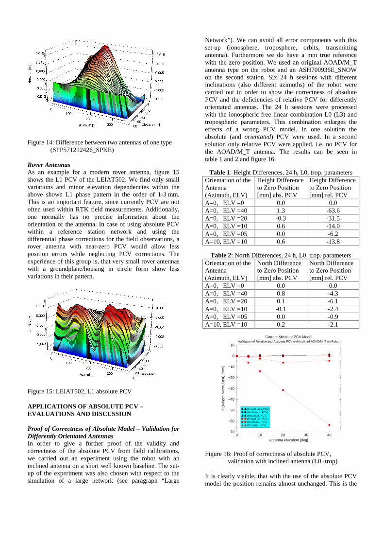
Figure 14: Difference between two antennas of one type (SPP571212426_SPKE) Rover Antennas As an example for a modern rover antenna, figure 15 shows the L1 PCV of the LEIAT502. We find only small variations and minor elevation dependencies within the above shown L1 phase pattern in the order of 1-3 mm. This is an important feature, since currently PCV are not often used within RTK field measurements. Additionally, one normally has no precise information about the orientation of the antenna. In case of using absolute PCV within a reference station network and using the differential phase corrections for the field observations, a rover antenna with near-zero PCV would allow less position errors while neglecting PCV corrections. The experience of this group is, that very small rover antennas with a groundplane/housing in circle form show less variations in their pattern.
Figure 15: LEIAT502, L1 absolute PCV APPLICATIONS OF ABSOLUTE PCV – EVALUATIONS AND DISCUSSION Proof of Correctness of Absolute Model – Validation for Differently Orientated Antennas In order to give a further proof of the validity and correctness of the absolute PCV from field calibrations, we carried out an experiment using the robot with an inclined antenna on a short well known baseline. The set-up of the experiment was also chosen with respect to the simulation of a large network (see paragraph “Large
Network”). We can avoid all error components with this set-up (ionosphere, troposphere, orbits, transmitting antenna). Furthermore we do have a mm true reference with the zero position. We used an original AOAD/M_T antenna type on the robot and an ASH700936E_SNOW on the second station. Six 24 h sessions with different inclinations (also different azimuths) of the robot were carried out in order to show the correctness of absolute PCV and the deficiencies of relative PCV for differently orientated antennas. The 24 h sessions were processed with the ionospheric free linear combination L0 (L3) and tropospheric parameters. This combination enlarges the effects of a wrong PCV model. In one solution the absolute (and orientated) PCV were used. In a second solution only relative PCV were applied, i.e. no PCV for the AOAD/M_T antenna. The results can be seen in table 1 and 2 and figure 16.
Table 1: Height Differences, 24 h, L0, trop. parameters Orientation of the Antenna (Azimuth, ELV)
Height Difference to Zero Position [mm] abs. PCV
Height Difference to Zero Position [mm] rel. PCV
A=0, ELV =0 0.0 0.0 A=0, ELV =40 1.3 -63.6 A=0, ELV =20 -0.3 -31.5 A=0, ELV =10 0.6 -14.0 A=0, ELV =05 0.0 -6.2 A=10, ELV =10 0.6 -13.8
Table 2: North Differences, 24 h, L0, trop. parameters Orientation of the Antenna (Azimuth, ELV)
North Difference to Zero Position [mm] abs. PCV
North Difference to Zero Position [mm] rel. PCV
A=0, ELV =0 0.0 0.0 A=0, ELV =40 0.8 -4.3 A=0, ELV =20 0.1 -6.1 A=0, ELV =10 -0.1 -2.4 A=0, ELV =05 0.0 -0.9 A=10, ELV =10 0.2 -2.1
0 10 20 30 40antenna elevation [deg]
−70
−60
−50
−40
−30
−20
−10
0
10
d (H
eigh
t,Nor
th,E
ast)
[mm
]
Correct Absolute PCV ModelValidation of Relative and Absolute PCV with Inclined AOAD/M_T on Robot
dHeight (abs. PCV)dNorth (abs. PCV)dEast (abs. PCV)dHeight (rel. PCV)dNorth (rel. PCV)dEast (rel. PCV)
Figure 16: Proof of correctness of absolute PCV, validation with inclined antenna (L0+trop)
It is clearly visible, that with the use of the absolute PCV model the position remains almost unchanged. This is the
correct solution, since the antenna was rotated and tilted within the same point. The use of relative PCV shows – dependent on the actual antenna inclination - height differences in the cm range and even horizontal changes (north component) in the mm range. The experiment on a short and well known baseline with almost no atmospheric and orbit effects is a rigorous proof of the correctness of the absolute PCV results from field calibrations. Relative PCV corrections are not sufficient and yield a difference to the true position. Mixed Short Baselines (24 h) A basic test of PCV models are observations on short mixed baselines. As an example from an extended evaluation (signals, linear combinations, elevation masks, modeling of troposphere) we show the results of a 24 h session using six different antenna types (table 3). The graph demonstrates the height difference compared to the results of a precise leveling between the pillars.
Table 3: Set-up of 24 h mixed short baselines Pillar Antenna Type
8 AOAD/M_T (height fixed) 7 ASH700936E_SNOW 6 JPSREGANT_DD_E 5 ASH700228D 4 ASH700700.B 3 ASH700228A
For this and the following comparisons we have chosen the NGS results (Mader 2000) as a relative model. The PCV from individual field calibrations were used for the absolute PCV correction. Some results can be seen in figure 17. The L1 results show, that both PCV models give correct and sufficient results for extended and long observations. The L0 coordinate estimation together with a modeling of tropospheric parameters yields good agreement with slightly advantages of the full absolute model (RMS values of all antennas). Remaining errors are still up to 1-2 cm for the height component. This is most probably due to mismodeling of MP as tropospheric changes. The station environment is known to be greatly affected by MP with individual differences of each pillar.
3 4 5 6 7 8pillar
−40
−35
−30
−25
−20
−15
−10
−5
0
5
10
15
20
25
30
35
40
dh [m
m]
Difference GPS to Ground Truth [mm] − 24 h sessionheight component, different solutions (L1, L0+trop, pcv−model)
L1 − absolute PCV (RMS=1.5 mm)L1 − relative PCV (RMS=1.6 mm)L0+trop − absolute PCV (RMS=6.6 mm)L0+trop − relative PCV (RMS=11.4 mm)
Figure 17: Height differences GPS to ground truth
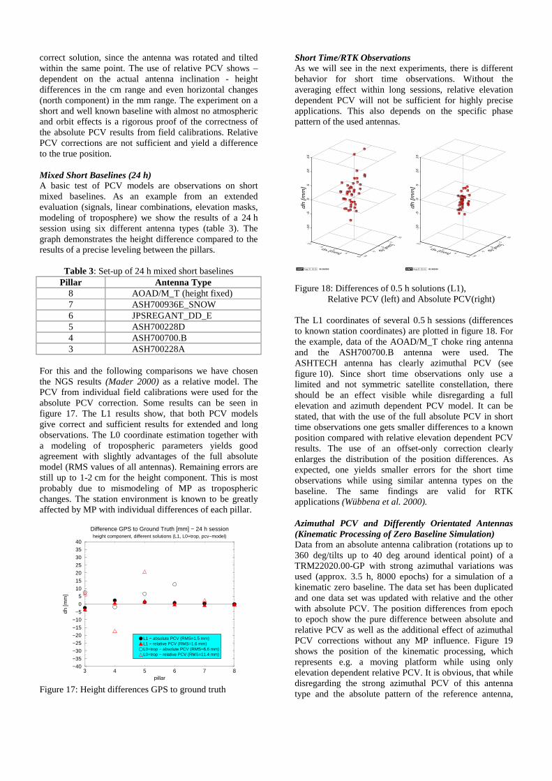
Short Time/RTK Observations As we will see in the next experiments, there is different behavior for short time observations. Without the averaging effect within long sessions, relative elevation dependent PCV will not be sufficient for highly precise applications. This also depends on the specific phase pattern of the used antennas.
GMT Aug 31 10:15 IfE 08/2000
-10-5
05
10
dx [mm]-10
-50
510
dy [mm]
-10
-50
51
01
5dh [m
m]
GMT Aug 31 10:15 IfE 08/2000
-10-5
05
10
dx [mm]-10
-50
510
dy [mm]
-10
-50
51
01
5dh [m
m]
Figure 18: Differences of 0.5 h solutions (L1), Relative PCV (left) and Absolute PCV(right) The L1 coordinates of several 0.5 h sessions (differences to known station coordinates) are plotted in figure 18. For the example, data of the AOAD/M_T choke ring antenna and the ASH700700.B antenna were used. The ASHTECH antenna has clearly azimuthal PCV (see figure 10). Since short time observations only use a limited and not symmetric satellite constellation, there should be an effect visible while disregarding a full elevation and azimuth dependent PCV model. It can be stated, that with the use of the full absolute PCV in short time observations one gets smaller differences to a known position compared with relative elevation dependent PCV results. The use of an offset-only correction clearly enlarges the distribution of the position differences. As expected, one yields smaller errors for the short time observations while using similar antenna types on the baseline. The same findings are valid for RTK applications (Wübbena et al. 2000). Azimuthal PCV and Differently Orientated Antennas (Kinematic Processing of Zero Baseline Simulation) Data from an absolute antenna calibration (rotations up to 360 deg/tilts up to 40 deg around identical point) of a TRM22020.00-GP with strong azimuthal variations was used (approx. 3.5 h, 8000 epochs) for a simulation of a kinematic zero baseline. The data set has been duplicated and one data set was updated with relative and the other with absolute PCV. The position differences from epoch to epoch show the pure difference between absolute and relative PCV as well as the additional effect of azimuthal PCV corrections without any MP influence. Figure 19 shows the position of the kinematic processing, which represents e.g. a moving platform while using only elevation dependent relative PCV. It is obvious, that while disregarding the strong azimuthal PCV of this antenna type and the absolute pattern of the reference antenna,
position differences of 1-2 cm and sometimes even larger can occur.
GMT Sep 4 14:55 IfE 09/2000
-20-15
-10-5
05
1015
20
dx [mm]-20
-15-10
-50
510
1520
dy [mm]
-15
-10
-50
51
01
52
0dh [m
m]
Figure 19: Simulation of kinematic zero-baseline. Position
differences between relative and absolute PCV. Large Network Generally, the current processing of global and regional networks uses relative PCV. Thus, all antenna’s PCV corrections do not incorporate the absolute phase pattern of the AOAD/M_T antenna (see figure 7). This is a deficiency, because simultaneously received satellite signals on various stations differ in their direction. Due to the lack of absolute information and because relative PCV always refer to identically orientated antennas, the applied PCV values are not sufficient. Evaluations of this group using absolute PCV for the AOAD/M_T antenna within a global network consisting of only this antenna type revealed a so-called “scale” of about 0.014 ppm between the uncorrected and the absolute PCV corrected solution (Menge et al. 1998). It must be mentioned, that the effect is not a pure scale resulting from the incorrect heights. Also horizontal variations may appear in dependence of the satellite constellation. Other research groups have done similar tests with absolute chamber PCV results using extended IGS data (e.g. Springer 2000). Various processing options have been tested (orbit estimation, estimation of satellite offsets etc.). Since there always appeared a scale while using absolute PCV, their use is not yet commonly accepted. But it is already widely realized, that the scale difference originates from other model parameters than the receiving PCV. The identification problem relies on the correlation of the receiver’s antenna behavior, the satellite’s antenna behavior, the treatment of tropospheric errors (e.g. estimating scale parameters) and the height component. We have already shown the validity of the absolute PCV with the experiment of an inclined antenna on the robot. The set-up (AOAD/M_T antenna, ASH700936E_SNOW antenna, 24 h observations, L0 linear combination, estimating tropospheric parameters) was selected also as a simulation for a large network. Thus, it is possible to avoid all error components (ionosphere, troposphere, orbits, transmitting antenna), whereas a separation of
individual error terms is difficult in large network processings. Furthermore we do have a mm true reference. We are able to simulate differently orientated antennas similar to a large network. The satellite constellation in the experiment is shifted over the antenna’s hemisphere and some satellites are blocked by the inclined antenna. Therefore, the change in the satellite constellation is not exactly the same as in an actual global network. The results in table 1, 2 and figure 16 with almost unchanged positions while using absolute PCV underline the necessity to introduce these corrections. The effects with relative PCV are similar to effects, which are found in comparison of both PCV models in large networks. The experiment shows, that the so-called “scale-problem” in large networks is unlikely a problem of the absolute PCV of the receiving antenna. Remarks Concerning Active Reference Networks and PCV Corrections More investigations are currently made within active reference station networks, where PDGPS corrections are transmitted for highly precise RTK positioning within the network. The correction of absolute PCV on the reference stations enhances a reliable and fast ambiguity resolution. Absolute PCV are the most complete correction for the operating of the network, even if MP effects may partly dominate the magnitude of azimuthal PCV. The MP research in this field is still evolving (see first paragraph). The investigations of absolute PCV within an active network lead to the so-called NULLANTENNA. This means, that all PCV effects within the network are removed and the transmitted phase data is – in an absolute sense - free of antenna errors. Some more remarks can be found in IfE and Geo++ (2000). SUMMARY AND CONCLUSIONS A highly precise and reliable automated field procedure for the calibration of absolute antenna PCV has been introduced and evaluated. The use of a calibrated robot and the automation within a real-time procedure while eliminating MP effects allows a high resolution of the estimated phase pattern. Even azimuthal PCV and PCV at the antenna’s horizon can be reliably and precisely determined for the first time. It could be shown, that some GPS antenna types do have azimuthal PCV which should not be neglected. The benefit of azimuthal PCV for precise positioning has been illustrated. Furthermore, near-field influences like groundplanes were subject of verification. Since absolute PCV are especially important for differently orientated antennas, the effects and the functionality of the absolute corrections were demonstrated and verified on a short baseline. In general, it could be demonstrated that the absolute PCV are working correctly. An experiment has been conducted, which showed, that the so-called “scale” change in large networks is unlikely caused by the receiving absolute PCV. Therefore, it is an urgent field of research to investigate and evaluate the remaining other influencing factors, i.e. the satellite antenna behavior and tropospheric
effects. Beside this problem, another field of important research is the effect of phase MP for precise applications. Precise corrections for PCV and MP are especially important for active reference station networks. ACKNOWLEDGMENTS The current project is funded by the German Ministry of Education, Science, Research and Technology (Bundesministerium für Bildung, Wissenschaft, Forschung und Technologie, BMBF) and Germany’s National Aerospace Research Center/National Space Agency (Deutsches Zentrum für Luft- und Raumfahrt, DLR) under the grant 50NA9809. REFERENCES IfE, Geo++ (2000): AOAD/M_T Choke Ring Antenna
Absolute Phase Center Variations, Results of Absolute PCV Field Calibrations at IfE and Geo++. Internet Publication compiled by F. Menge and M. Schmitz, world wide web (WWW): http://www.ife.uni-hannover.de/~web/AOA_DM_T.
Mader, G. (2000). Calibration of GPS Antennas. NOAA, NOS, NGS, GRD, world wide web (WWW): http:// www.grdl.noaa.gov/GRD/GPS/Projects/ANTCAL.
Mader, G. (1999). GPS Antenna Calibration at the National Geodetic Survey. GPS Solutions, Vol. 3, No. 1, Summer 1999, Wiley.
Menge, F., V. Böder, H. Leistner, G. Seeber, G. Wübbena, M. Schmitz (2000): Absolute Feldkalibrierung von GPS-Antennen – Entwicklung und Grundlagen. Workshop Proceedings, GPS-Antennenworkshop, Institut für Erdmessung, Universität Hannover, Hannover, Germany, May 10, 2000.
Menge, F., G. Seeber (2000): Untersuchungen und Beiträge zur Problematik der Phasenzentrums-variationen von GPS Antennen. In: Dietrich, R. (Ed.). Deutsche Beiträge zu GPS-Kampagnen des Scientific Committe in Antarctic Research (SCAR) 1995-1998, DGK, Reihe B, Nr. 310.
Menge, F., G. Seeber, C. Völksen, G. Wübbena, M. Schmitz (1998): Results of Absolute Field Calibration of GPS Antenna PCV. Proceedings of the 11th International Technical Meeting of the Satellite Division of the Institute of Navigation, ION GPS-98, Nashville, Tennessee, USA, September 15-18, 1998.
Mora-Castro, E.J., C. Carrascosa-Sanz, G. Ortega (1998): Characterisation of the Multipath Effects on the GPS Pseudorange and Carrier Phase Measurements. Proceedings of the 11th International Technical Meeting of the Satellite Division of the Institute of Navigation, ION GPS-98, Nashville, Tennessee, USA, September 15-18, 1998.
Ray, J.K. (2000): Mitigation of GPS Code and Carrier Phase Multipath Effects Using a Multi-Antenna System. PhD Thesis, Department of Geomatics Engineering, University of Calgary, Alberta, Canada, UCGE Reports Number 20136.
Rothacher, M., S. Schaer, L. Mervart, G. Beutler (1995). Determination of Antenna Phase Center Variations Using GPS Data. In: Gendt, G. and G. Dick (Eds.). Special Topics and New Directions, IGS Workshop Proceedings, Potsdam, Germany, May 15-17, 1995.
Schupler, B.R. (1994). Signal Characteristics of GPS User Antennas. NAVIGATION: Journal of The Institut of Navigation, Vol. 41, No. 3, Fall 1994, USA.
Schupler, B.R., T.A. Clark, R.L. Allshouse (1995). Characterizations of GPS User Antennas: Reanalysis and New Results. In: Beutler, G. et al. (Eds.). GPS Trends in Precise Terrestrial, Airborne, and Spaceborne Applications, IAG Symposia, Vol. 115, Boulder, CO, USA, July 3-4, 1995, Springer Verlag.
Seeber, G., F. Menge, C. Völksen, G. Wübbena, M. Schmitz (1998). Precise GPS Positioning Improvements by Reducing Antenna and Site Dependent Effects. In: Brunner (Ed.). Advances in Positioning and Reference Frames, IAG Symposia, Vol. 118, Rio de Janeiro, Brasil, September 3-9, 1997, Springer Verlag.
Springer, T. (2000). Common Interests of the IGS and the IVS. In: International VLBI Service for Geodesy and Astrometry 2000 General Meeting Proceedings, Kötzing, Germany, February 21-24, 2000, edited by Nancy R. Vandenberg and Karen D. Baver, NASA/CP-2000-209893,2000.
UNAVCO (1995). Receiver and Antenna Test Report. University Navstar Consortium (UNAVCO) Academic Research Infrastructure (ARI), Boulder, Colorado.
Wanninger, L., M. May (2000): Carrier Phase Multipath Calibration of GPS Reference Stations. Proceedings of the 13th International Technical Meeting of the Satellite Division of the Institute of Navigation, ION GPS-2000, Salt Lake City, Utah, USA, September 19-22, 2000.
Wübbena, G., M. Schmitz, G. Boettcher, F. Menge, V. Böder, H. Leistner, G. Seeber (2000): Absolute Feldkalibrierung von GPS-Antennen – Ergebnisse. Workshop Proceedings, GPS-Antennenworkshop, Institut für Erdmessung, Universität Hannover, Hannover, Germany, May 10, 2000.
Wübbena, G., M. Schmitz, F. Menge, G. Seeber, C. Völksen (1997). A New Approach for Field Calibration of Absolute GPS Antenna Phase Center Variations. NAVIGATION: Journal of The Institut of Navigation, Vol. 44, No. 2, Summer 1997, USA.