Embed Size (px)
Citation preview
8411.801/6--90Betriebsanleitung / Instructions de Service / Operating Instructions
BOAX--B
BOAX--B BOAX--B Mat P
1. Konformitätserklärung / Déclaration de conformité / Declaration of conformity.............................. 22. Einbauerklärung für Teilmaschinen....................................................................................................... 4
Déclaration d’incorporation pour quasi machine................................................................................. 5Declaration of incorporation for partly completed machinery............................................................ 6
3. Allgemeine Hinweise............................................................................................................................... 74. Sicherheit.................................................................................................................................................. 75. Transport und Lagerung......................................................................................................................... 86. Beschreibung der Armaturen................................................................................................................. 87. Einbau....................................................................................................................................................... 108. Betrieb/Inbetriebnahme........................................................................................................................... 129. Wartung / Instandhaltung........................................................................................................................ 1210. BOAX--B Mat P.......................................................................................................................................... 1411. Störungen / Ursachen und Beseitigungitung ....................................................................................... 16
3. Généralités............................................................................................................................................... 174. Sécurité..................................................................................................................................................... 175. Transport et stockage intermédiaire................................................................................................... 186. Description des robinets....................................................................................................................... 187. Installation................................................................................................................................................ 208. Mise en service et mise à l’arrêt ............................................................................................................ 229. Maintenance / Réparations................................................................................................................... 2210. BOAX--B Mat P.......................................................................................................................................... 2411. Incidents de fonctionnement................................................................................................................ 26
3. General...................................................................................................................................................... 274. Safety......................................................................................................................................................... 275. Transport and interim storage............................................................................................................. 286. Description of valves............................................................................................................................ 287. Installation................................................................................................................................................ 308. Commissioning / Decommissioning.................................................................................................... 329. Maintenance / Repair............................................................................................................................. 3210. BOAX--B Mat P.......................................................................................................................................... 3411. Commissioning / Decommissioning.................................................................................................... 36
42407263
2
1. Konformitätserklärung / Déclaration de conformité / Declaration of conformity
Hiermit erklären wir,Par la présente nous,Hereby we,
KSB S.A.S.Zone industrielle Gagnaire Fonsèche24490 LA ROCHE CHALAISSitz / Siège social / Registered Office:92635 -- GennevilliersFrance
dass die nachstehend aufgeführten Produkte folgende Anforderungen erfüllen:déclarons que les robinets définis ci--après sont conformes :declare that the valves listed below comply:
-- die Anforderungen der Druckgeräterichtlinie 97/23/EG.-- with the requirements of the Pressure Equipment Directive 97/23/EC.-- with the requirements of the Pressure Equipment Directive 97/23/EC.
Beschreibung der Armaturen -- Baureihen:Description des types de robinets:Description of the valve types
Absperrklappe / Robinets à papillon / Butterfly valvesBOAX---B PS 10/16 bar DN 40--1000
Gemäß harmonisierten europ. Normen:Selon les normes Européennes harmonisées :As per harmonized European standards:
EN 12516--2:2004 ; EN 12516--4:2008
und andere Normen / Regelwerke:et autres normes / directives :and other standards / directives:
EN 1563 ; ASME B16.42 ; EN 593 ; EN 10213--4
geeignet für:conviennent pour les :Suitable for:
Flüssigkeiten Gruppe 1 (mit Ringbalg K) und Fluidgruppe 2 (mit Ringbalg XC)Liquides groupe 1 (avec manchette K) et fluides groupe 2 (avec manchette XC)Liquid group 1 (with liner K) and fluid group 2 (with liner XC)
Konformitätsbewertungsverfahren:Procédure d’évaluation de la conformité :Conformity Assessment Procedure:
Modul HModule HModule H
Werk :Sites de productions :Production sites :
LA ROCHE CHALAIS / BURGOS
Name und Anschrift der benannten Stelle fürBestellungen, bis 30/09/2011 gemacht wurden:Nom et adresse de l’organisme notifié pourles commandes fabriquées jusqu’au 30/09/11 :Name and address of the notified bodyfor orders until 30/09/2011:
Lloyd’s Register Verification Limited71 Fenchurch Street,LondonEC3M 4BSEngland
Nummer der benannten Stelle:Numéro d’identification :Number of notified body:
0038
Zertifikat--Nummer:Numéro du certificat :Number of certificate:
RPS 0160325/01
Name und Anschrift der benannten Stelle fürBestellungen, die ab 01/10/2011 gemacht wurden:Nom et adresse de l’organisme notifié pourles commandes fabriquées à partir du 01/10/2011:Name and address of the notified bodyfor orders made from 01/10/2011:
Bureau Veritas67/71 boulevard du Château92200 Neuilly--sur--SeineFRANCE
Nummer der benannten Stelle:Numéro d’identification :Number of notified body:
0062
Zertifikat--Nummer:Numéro du certificat :Number of certificate:
CE--PED--H--KSB 001--11--FRA
3
Werk :Sites de productions :Production sites :
DALIAN
Name und Anschrift der benannten Stelle:Nom et adresse de l’organisme notifié :Name and address of the notified body:
Lloyd’s Register Verification Limited71 Fenchurch Street,LondonEC3M 4BSEngland
Nummer der benannten Stelle:Numéro d’identification :Number of notified body:
0038
Zertifikat--Nummer:Numéro du certificat :Number of certificate:
RPS 0160325/01
Armaturen DN ≤ 50 entsprechen der Druckgeräterichtlinie 97/23/EG Art. 3 §3. Sie dürfen deshalb weder mit einem CE--Zeichen noch mitder Nummer einer benannten Stelle gekennzeichnet sein.Les robinets DN ≤ 50 sont conformes à la Directive Equipement Sous Pression 97/23/CE Art. 3 §3. Ils ne doivent pas être marqués dusymbole CE suivi du numéro d’identification de l’organisme notifié.Valves DN ≤ 50 comply with the Pressure Equipment Directive 97/23/EC Art. 3 §3. They must not bear neither the CE--Label nor thenumber of the notified body.
-- die Anforderungen der Berichtigung der Verordnung REACH 1907/2006/EG.-- aux exigences du règlement REACH CE 1907/2006.-- with the requirements of the regulation EC REACH 1907/2006.
Berichtigung der Verordnung EG 1907/2006 des Europäischen Parlaments zur Registrierung, Bewertung, Zulassung und Beschränkungchemischer Stoffe (REACH)Règlement CE 1907/2006 du Parlement européen concernant l’enregistrement, l’évaluation et l’autorisation des substances chimiques,ainsi que les restrictions applicables à ces substancesRegulation EC 1907/2006 on the registration, evaluation, authorization and restrictions of chemicals
Beschreibung der Armaturen -- Baureihen:Description des types de robinets:Description of the valve types
Absperrklappe / Robinets à papillon / Butterfly valvesBOAX---B PS 10/16 bar DN 40--1000
Artikel 33/REACHArticle 33/REACHArticle 33/REACH
Keine Substanz, aus dem Verzeichnis der für eine Zulassungsflicht in Fragekommenden Stoffe und im Anhang XIV, ist in einer Konzentration von mehr als 0,1%(w/w) enthaltenAucune substance incluse dans la liste candidate et dans l’annexe XIV de la réglemen----tation n’est présente à une concentration supérieure à 0,1% (en masse/masse)None of substances included in the candidate list and in Annex XIV of this regulationare present in our actuators above a concentration of 0,1% (weight by weight)
Michel DelobelQuality Assurance
Dieses Dokument wurde elektronisch erstellt und ist daher auch ohne Unterschrift gültig.Ce document est réalisé électroniquement, il est donc valable sans signature. Sa mise dans le domaine public valide son état. Rev.4-- 07/11This document was prepared electronically and is valid without signature.
4
2. Einbauerklärung für TeilmaschinenMaschinenrichtlinie 2006/42/EC
Hiermit erklären wir, KSB S.A.S.Zone industrielle Gagnaire Fonsèche24490 LA ROCHE CHALAISSitz: 92635 -- GennevilliersFrankreich
Hersteller für die folgende Teilmaschinen Typ:Aggregate: Absperrklappe + automatischer Antrieb + Stellungsregler oder Endlagenschalter
Absperrklappe Typ: -- BOAX--B, BOAX--N, BOAX--S, BOAX--SF-- BOAXMAT--N, BOAXMAT--S, BOAXMAT--SF, BOAX--B Mat P,
BOAX--B Mat E-- ISORIA 10, ISORIA 16, ISORIA 20, ISORIA 25-- KE-- MAMMOUTH 6, 10, 16, 20, 25-- DANAÏS 150, DANAIS MTII, DANAIS TBT
mit Antrieb Typ: -- Elektrisch: ACTELEC-- Pneumatisch: ACTAIR et DYNACTAIR-- Hydraulisch: ACTO, DYNACTO, ENNACTO-- Fallgewichtsantrieb: Serie R380 und R480
und ausgestattet wahlweise mit Stellungsregleroder Endlagenschalter Typ:
-- AMTROBOX -- Alle Typen ---- AMTROBOX R -- Alle Typen ---- AMTROBOX C R1290-- AMTROBOX S R1195-- R1077 / R1078 / R1079 / R1158-- AMTRONIC / SMARTRONIC -- Alle Typen-- R1011 / R886 / R1007 / R834
dass die folgenden grundlegenden Anforderungen der Maschinenrichtlinie 2006/42/EG Anhang I zur Anwendung kommenund erfüllt werden:
1.1.3, 1.1.5, 1.2.1, 1.3.2, 1.3.4, 1.3.7, 1.3.8, 1.3.8.1, 1.4.1, 1.4.2.1, 1.5.1, 1.5.2, 1.5.3, 1.5.4, 1.5.7, 1.5.8, 1.6.1, 1.7.2,2.1.1 a, b, e
Die speziellen technischen Unterlagen gemäß Anhang VII Teil B wurden erstellt.
Diese werden auf begründetes Verlangen vollständig oder teilweise auf dem Postweg oder elektronisch zur Verfügunggestellt. Verantwortlicher für die Zusammenstellung der technischen Unterlagen ist:
Nicolas Lefrancq -- KSBParc d’activité Rémora33170 Gradignan, France
Andere Richtlinie als Referenz: PED 97/23/CE
ATEX Richtlinie 94/9/CE
Die unvollständige Maschinen darf erst dann in Betrieb genommen werden, wenn gegebenenfalls festgestellt wurde, dassdie Maschine, in die die unvollständige Maschine eingebaut werden soll, den Bestimmung der Maschinenrichtlinie2006/42/EG entspricht.
Michel DelobelQualitätsmanagement
Rév.4 -- 07/11
Dieses Dokument wurde elektronisch erstellt und ist daher auch ohne Unterschrift gültig.Mit seiner Veröffentlichung erlangt es Gültigkeit.
5
2. Déclaration d’incorporation pour quasi machineDirective relative aux machines 2006/42/CE
Par la présente nous, KSB S.A.S.Zone industrielle Gagnaire Fonsèche24490 LA ROCHE CHALAIS
Siège social : 92635 -- GennevilliersFrance
Le constructeur des quasi machines, pour les agrégats suivants du type:robinet + actionneur automatique + signalisation ou positionneur
Robinets à papillon du type : -- BOAX--B, BOAX--N, BOAX--S, BOAX--SF-- BOAXMAT--N, BOAXMAT--S, BOAXMAT--SF, BOAX--B Mat P,
BOAX--B Mat E-- ISORIA 10, ISORIA 16, ISORIA 20, ISORIA 25-- KE-- MAMMOUTH 6, 10, 16, 20, 25-- DANAÏS 150, DANAIS MTII, DANAIS TBT
Avec actionneurs du type : -- Electriques : ACTELEC-- Pneumatiques : ACTAIR et DYNACTAIR-- Hydrauliques : ACTO, DYNACTO, ENNACTO-- Masse Motrice : Série R380 et R480
et muni optionnellement de boîtiers designalisation ou positionneurs du type :
-- AMTROBOX -- Tous types ---- AMTROBOX R -- Tous types ---- AMTROBOX C R1290-- AMTROBOX S R1195-- R1077 / R1078 / R1079 / R1158-- AMTRONIC / SMARTRONIC -- Tous Types-- R1011 / R886 / R1007 / R834
déclarons que les exigences essentielles appliquées ci--dessous :
1.1.3, 1.1.5, 1.2.1, 1.3.2, 1.3.4, 1.3.7, 1.3.8, 1.3.8.1, 1.4.1, 1.4.2.1, 1.5.1, 1.5.2, 1.5.3, 1.5.4, 1.5.7, 1.5.8, 1.6.1, 1.7.2,2.1.1 a, b, e
et stipulées dans l’annexe I de la Directive 2006/42/CE ont été prises en compte et respectées.Les documents techniques ont été constitués conformément à l’Annexe VII, partie B.
Si les autorités compétentes le souhaitent, nous mettrons à disposition les documents spécifiques techniques indiquéspar voie postale ou par voie électronique. Ils peuvent être demandés auprès de:
Nicolas Lefrancq -- KSBParc d’activité Rémora33170 Gradignan, France
Autres Directives utilisées : Directive des équipements sous pression 97/23/CE
Directive ATEX 94/9/CE
La quasi machine relative à la présente déclaration d’incorporation ne doit pas être mise en service avant que lamachine dans laquelle elle sera incorporée n’aura été déclarée conforme aux dispositions de la Directive 2006/42/CE.
Michel DelobelAssurance qualité
Rév.4 -- 07/11
Ce document est réalisé électroniquement, il est donc valable sans signature. Sa mise dans le domaine public valide son état.
6
2. Declaration of incorporation for Partly Completed machineryMachinery Directive 2006/42/EC
Hereby, we,: KSB S.A.S.Zone industrielle Gagnaire Fonsèche24490 LA ROCHE CHALAISRegistered Office: 92635 -- GennevilliersFrance
Manufacturer of the partly completed machine (PCM) for following product aggregate of type: valve + automatic actuator +automation
Butterfly valves of type: -- BOAX--B, BOAX--N, BOAX--S, BOAX--SF-- BOAXMAT--N, BOAXMAT--S, BOAXMAT--SF, BOAX--B Mat P,
BOAX--B Mat E-- ISORIA 10, ISORIA 16, ISORIA 20, ISORIA 25-- KE-- MAMMOUTH 6, 10, 16, 20, 25-- DANAÏS 150, DANAIS MTII, DANAIS TBT
Actuators of type : -- Electric: ACTELEC-- Pneumatic: ACTAIR et DYNACTAIR-- Hydraulic: ACTO, DYNACTO, ENNACTO-- Counterweight: Series R380 and R480
optionally with limit swich or automation boxesof type:
-- AMTROBOX -- All types ---- AMTROBOX R -- All types ---- AMTROBOX C R1290-- AMTROBOX S R1195-- R1077 / R1078 / R1079 / R1158-- AMTRONIC / SMARTRONIC -- All Types-- R1011 / R886 / R1007 / R834
declare the following essential requirements of the annex I of the Machine Directive 2006/42/EC are applied and fullfilled:
1.1.3, 1.1.5, 1.2.1, 1.3.2, 1.3.4, 1.3.7, 1.3.8, 1.3.8.1, 1.4.1, 1.4.2.1, 1.5.1, 1.5.2, 1.5.3, 1.5.4, 1.5.7, 1.5.8, 1.6.1, 1.7.2,2.1.1 a, b, e
The relevant technical documentation is compiled in accordance with part B of Annex VII.
This documentation of parts hereof will be transmitted by post or electronically in response to a reasoned request by thenational authorities. The person authorised to compile the relevant thecnical documentation by:
Nicolas Lefrancq -- KSBParc d’activité Rémora33170 Gradignan, France
Other EC--Directives to be used: Pressure Equipment Directive -- PED -- 97/23/EC
Directive ATEX 94/9/EC
This partly completed machinery must not be put into service until the final machinery into which it is to be incorporatedhas been declared in conformity with the provisions of the Machinery Directive 2006/42/EC, where appropriate.
Michel DelobelQuality Assurance
Rév.4 -- 07/11
This document was prepared electronically and is valid without signature.Its implementation in the public domain validates his condition.
7
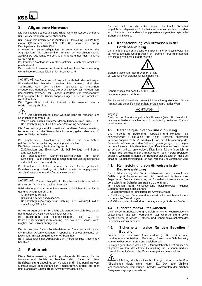
3. Allgemeine HinweiseDie vorliegende Betriebsanleitung gilt für weichdichtende, zentrischeKSB--Absperrklappen (siehe Abschnitt 5).
KSB-Armaturen unterliegen in Auslegung, Herstellung und Prüfungeinem QS-System nach EN ISO 9001 sowie der Europ.Druckgeräterichtlinie 97/23/EG.In einem Armaturenkonfiguration mit automatischen Antrieb dasAggregat kann als Teilmaschinen im Sinn der Maschinenrichtlinie2006/42/EC betrachtet werden. Die Anforderungen der Richtliniewerden erfüllt.Bei korrekter Montage ist ein störungsfreier Betrieb der Armaturengewährleistet.Der Hersteller übernimmt für diese Armaturen keine Verantwortung,wenn diese Betriebsanleitung nicht beachtet wird.
ACHTUNG Die Armaturen dürfen nicht außerhalb des zulässigenEinsatzbereiches betrieben werden. Die Grenzen sind demTypenschild oder dem gültigen Typenblatt zu entnehmen.Insbesondere dürfen die Werte der Druck-Temperatur-Tabellen nichtüberschritten werden. Der Einsatz außerhalb von vorgenanntenBedingungen führt zu Überbeanspruchungen, denen die Armaturennicht standhalten.Die Typenblätter sind im Internet unter www.ksb.com --Produktkatalog abrufbar.
Das Nichtbeachten dieser Warnung kann zu Personen- undSachschäden führen, z. B.-- Verletzungen durch austretende Medien (kalt/heiß, unter Druck, . . . ),-- Beeinträchtigung der Funktion oder Zerstörung der Armatur.
Die Beschreibungen und Instruktionen in dieser Betriebsanleitungbeziehen sich auf die Standardausführungen, gelten aber auch ingleicher Weise für Varianten.
Bei angetriebenen Armaturen ist zusätzlich die zum Antriebgehörende Betriebsanleitung unbedingt einzuhalten.Die Betriebsanleitung berücksichtigt nicht-- Zufälligkeiten und Ereignisse, die bei Montage und Betrieb
auftreten können,-- die ortsbezogenen Sicherheitsbestimmungen, für deren
Einhaltung -- auch seitens des hinzugezogenen Montagepersonals-- der Betreiber verantwortlich ist.
Bei Armaturen mit Antrieb ist auch die zum Antrieb gehörendeBetriebsanleitung unbedingt einzuhalten sowie die angegebenenAnschlußparameter und die Anbauanweisungen.
ACHTUNG Voraussetzung für das Handhaben der Armatur ist derEinsatz von fachlich geschultem Personal.
Fehlbedienung einer Armatur kann zu nachdrücklichen Folgen für diegesamte Anlage führen, z. B.-- Austritt des Mediums,-- Stillstand einer Anlage/Maschine,-- Beeinträchtigung/Verringerung/Erhöhung der Wirkung/Funktion
einer Anlage/Maschine.
Bei Rückfragen oder im Schadensfalle wenden Sie sich bitte an dienächstgelegene KSB-Verkaufsniederlassung.Bei Rückfragen und Nachbestellungen, bitten wir, dieBaureihen-/Ausführungsbezeichnung, die Werk-Nr. sowie, wennmöglich, das Baujahr anzugeben.
Die technischen Daten (Betriebsdaten) der Armaturen sind in dentechnischen Dokumentationen (Typenblatt, Betriebsanleitung) derjeweiligen Armatur aufgeführt (siehe Abschnitt 5).Bei Rücksendung der Armaturen zum Hersteller bitte Abschnitt 4beachten.
4. SicherheitDiese Betriebsanleitung enthält grundlegende Hinweise, die beiMontage und Betrieb zu beachten sind. Daher ist dieseBetriebsanleitung unbedingt vor Montage und Inbetriebnahme vomMonteur sowie dem zuständigen Fachpersonal/Betreiber zu lesenund ständig am Einsatzort der Armatur verfügbar sein.
Es sind nicht nur die unter diesem Hauptpunkt Sicherheitaufgeführten, allgemeinen Sicherheitshinweise zu beachten, sondernauch die unter den anderen Hauptpunkten eingefügten, speziellenSicherheitshinweise.
4.1. Kennzeichnung von Hinweisen in derBetriebsanleitung
Die in dieser Betriebsanleitung enthaltenen Sicherheitshinweise, diebei Nichtbeachtung Gefährdungen für Personen hervorrufen können,sind mit allgemeinem Gefahrensymbol
Sicherheitszeichen nach ISO 3864--B.3.1,bei Warnung vor elektrischer Spannung mit
Sicherheitszeichen nach ISO 3864--B.3.6.besonders gekennzeichnet.
Bei Sicherheitshinweisen, deren Nichtbeachtung Gefahren für dieArmatur und deren Funktionen hervorrufen kann, ist das Wort
ACHTUNGeingefügt.Direkt an der Armatur angebrachte Hinweise (wie z.B. Nenndruck)müssen unbedingt beachtet und in vollständig lesbarem Zustandgehalten werden.
4.2. Personalqualifikation und -SchulungDas Personal für Bedienung, Inspektion und Montage dieentsprechende Qualifikation für diese Arbeiten aufweisen.Verantwortungsbereich, Zuständigkeit und die Überwachung desPersonals müssen durch den Betreiber genau geregelt sein. Liegenbei dem Personal nicht die notwendigen Kenntnisse vor, so ist dieseszu schulen und zu unterweisen. Dies kann, falls erforderlich, imAuftrag des Betreibers der Armatur durch den Hersteller/Lieferererfolgen. Weiterhin ist durch den Betreiber sicherzustellen, dass derInhalt der Betriebsanleitung durch das Personal voll verstanden wird.
4.3. Kennzeichnung von Hinweisen in derBetriebsanleitung
Die Nichtbeachtung der Sicherheitshinweise kann sowohl eineGefährdung für Personen als auch für Umwelt und die Armatur zurFolge haben. Die Nichtbeachtung der Sicherheitshinweise kann zumVerlust jeglicher Schadensersatzansprüche führen.Im einzelnen kann Nichtbeachtung beispielsweise folgendeGefährdungen nach sich ziehen:-- Versagen wichtiger Funktionen der Armatur/Anlage,-- Gefährdung von Personen durch elektrische, mechanische und
chemische Einwirkungen,-- Gefährdung der Umwelt durch Leckage von gefährlichen Stoffen.
4.4. Sicherheitsbewußtes ArbeitenDie in dieser Betriebsanleitung aufgeführten Sicherheitshinweise, diebestehenden nationalen Vorschriften zur Unfallverhütung sowieeventuelle interne Arbeits-, Betriebs- und Sicherheitsvorschriften desBetreibers sind zu beachten.
4.5. Sicherheitshinweise für den Betreiber /Bediener
Führen heiße oder kalte Armaturenteile (z. B. Gehäuse oderHandhebel oder Antriebe) zu Gefahren, müssen diese Teile bauseitigvom Betreiber gegen Berührung gesichert sein.Leckagen gefährlicher Medien (z.B. feuergefährlich, heiß) müssen soabgeführt werden, dass keine Gefährdung für Personen und dieUmwelt besteht. Gesetzliche Bestimmungen sind einzuhalten.
Gefährdung durch elektrische Energie ist auszuschließen.(Einzelheiten hierzu siehe Norm IEC 364 oder ähnlichelandesspezifische Vorschriften und/oder Vorschriften der örtlichenEnergieversorgungsunternehmen.
8
4.6. Sicherheitshinweise für Inspektions- undMontagearbeiten
4.6.1 Allgemeines
Für eine angetriebene Armatur müssen sowohl die vorgeschriebeneVorgehensweise der Armaturbetriebsanleitung als auch die derBetriebsanleitungen des automatischen Antriebs, desStellungsreglers oder Endlagenschalters eingehalten werden.
Der Betreiber hat dafür zu sorgen, dass alle Inspektions- undMontagearbeiten von autorisiertem und qualifiziertem Fachpersonalausgeführt werden, das sich durch eingehendes Studium derBetriebsanleitung ausreichend informiert hat.Arbeiten an den Armaturen dürfen nur vorgenommen werden, wenn dieArmaturen nicht mehr unter Druck stehen und auf 60 ° C abgekühlt sind.Vor Arbeiten an Armaturen mit Antrieben müssen die elektrischenAnschlüsse des Stellantriebes von der Stromversorgung abgeklemmtsind. Die in der Betriebsanleitungen vorgeschriebeneVorgehensweise zum Stillsetzen des Stellantriebes muss unbedingteingehalten werden.Armaturen, die mit gesundheitsgefährdenden Medien in Berührungkommen, müssen dekontaminiert werden.Unmittelbar nach Abschluß der Arbeiten müssen alle Sicherheits- undSchutzeinrichtungen wieder angebracht bzw. in Funktion gesetzt werden.Vor der Wiederinbetriebnahme sind die im Abschnitt Inbetriebnahmeaufgeführten Punkte zu beachten.
4.6.2 EndarmaturAls Endarmatur und Demontage der nicht unter Druck stehendenRohrleitung bei Umgebungstemperatur der Standardarmaturen.Die Montage der Absperrklappe BOAX--B Typ 2, 4 und 5 erfolgtzwischen Flanschen ohne zusätzliche Dichtung mittelsGewindestangen.
Gas oder gefährlich** All DN: nicht erlaubtGas oderFlüssig-keiten*
Nichtgefährlich**
DN ≤ 200: ∆PS = 10 bar max.DN 250 bis 500: ∆PS = 7 bar max.
Flüssig-keiten*
gefährlich**DN ≤ 200: ∆PS = 10 bar max.DN > 200: ∆PS = 7 bar max.Flüssig-
keiten* Nichtgefährlich**
DN ≤ 200: ∆PS = 10 bar max.DN > 200: ∆PS = 7 bar max.
∆PS: Differenzdruck
* Medien, deren Dampfdruck bei max. zulässiger Temperatur wenigeroder genau 0,5 bar über dem normalen Atmosphärendruck (1013mbar) liegt, werden als Flüssigkeiten betrachtet.
** Gefährliche und ungefährliche Medien gemäß Klassifikation der DGR.Anmerkung: Eine Armatur, die am Ende einer Rohrleitung miteinem Blindflansch eingebaut ist, ist nicht mit einer Endarmaturgleichzusetzen.
Anmerkung: Eine Armatur, die am Ende einer Rohrleitung mit einemBlindflansch eingebaut ist, ist nicht mit einer Endarmatur gleichzusetzen.
4.7. Eigenmächtiger Umbau undErsatzteilherstellung
Umbau oder Veränderungen der Armatur sind nur nach Absprachemit dem Hersteller zulässig. Originalersatzteile und vom Herstellerautorisiertes Zubehör dienen der Sicherheit. Die Verwendung andererTeile kann die Haftung für die daraus entstehenden Folgen aufheben.
4.8. Unzulässige BetriebsweisenDie Betriebssicherheit der gelieferten Armatur ist nur beibestimmungsgemäßer Verwendung entsprechend AbschnittAllgemeines der Betriebsanleitung gewährleistet. Die in dertechnischen Dokumentation angegebenen Grenzwerte dürfen aufkeinen Fall überschritten werden.
5. Transport und Lagerung5.1. TransportDie Armaturen werden in betriebsfertigem Zustand geliefert.
ACHTUNG Bei Transport und Zwischenlagerung müssen sich dieArmaturen immer in halb geöffneter Stellung befinden und in einemKarton verpackt sein.
ACHTUNG Die Armatur darf weder am Hals noch am Handradoder am Antrieb angeschlagen werden.Nach der Lieferung bzw. vor dem Einbau ist die Armatur aufTransportschäden zu überprüfen.
5.2. Lagerung
Die Armaturen müssen so gelagert werden, dass selbst nach längererLagerzeit ein ordnungsgemäßes Funktionieren gewährleistet ist:
-- Während der Lagerung beträgt der Öffnungswinkel der Klappe 5°.-- Geeignete Maßnahmen gegen Verschmutzung, Frost und
Korrosion müssen getroffen werden.
6. Beschreibung der ArmaturenZeichnungen und weitere Informationen zu den Armaturenbaureihenfinden Sie in den entsprechenden Baureihenheften:
Typ DN PS (bar) Reihungs--Nr.BOAX--B 40--1000 10/16 8409.11
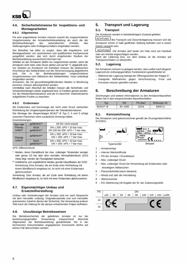
6.1. KennzeichnungDie Armaturen sind gekennzeichnet gemäß der Druckgeräterichtlinie97/23/EG.
Typenschild
01/07XXXXXXX
12 3
4 56
78 9
Beispiel
1 -- Armaturentyp
2 – Interner Werkstoffcode
3 -- PN der Armatur / Druckklasse
4 – Max. zulässiger Druck
5 – Max. zulässiger Druck bei Verwendung als Endarmatur oder
einseitigem Abflanschen
6 -- Flanschbohrbild (wenn bekannt)
7 – Monat und Jahr der Herstellung
8 -- Werksnummer
9 – EG--Markierung mit Angabe der Nr. der Zulassungsstelle
PS DN≤32 40 50 65 80 100 125 150 ≥200
10
16

9
6.2 Zeichnungen und Dokumente
100
412
310.1
970.1
310.2
213
550
310.3
413
210
916
100
412
310.1
900.1
970.1
310.2
213
550
310.3
413
210
916
310.4
900.2
DN 250 bis 600 DN 650 bis 1000
932.1
100
940
412.2
213
550
210
561
540
310.1
413
412.1
970.1
176
310.2
920
904
310.3
412.3
932.2
486
916
932
DN 40 bis 200
6.3 Teileverzeichnis
Teile--Nr Benennung DN100 Gehäuse 40 bis 1000176 Boden 650 bis 1000210 Welle 40 bis 1000213 Antriebswelle 40 bis 1000310.1 Lager 40 bis 1000310.2 Lager 40 bis 1000310.3 Lager 40 bis 1000310.4 Lager 350 bis 600412 O--ring 40 bis 600412.1 O--ring 650 bis 1000412.2 O--ring 650 bis 1000412.3 O--ring 650 bis 1000413 Ringbalg 40 bis 1000486 Kugel 650 bis 1000540 Buchse 650 bis 1000550 Scheibe 40 bis 1000561 Kerbstift 650 bis 1000900.1 Ausblassicherung 40 bis 600900.2 Ausblassicherung 250 bis 600904 Stellschraube 650 bis 1000916 Stopfen 40 bis 1000920 Mutter 650 bis 1000932 Sicherungsring 40 bis 200932.1 Sicherungsring 650 bis 1000932.2 Sicherungsring 650 bis 1000940 Passfeder 650 bis 000970.1 Typenschild 40 bis 1000
10
6.4. Funktionsweise
BeschreibungDie Hauptbestandteile der Armatur sind das Gehäuse (100), dieAntriebswelle (213), die Welle (210), die Klappenscheibe (550) undder Ringbalg (413).
Durch die Formulierung des Ringbalges und seine Herstellung imHause wird absolute Dichtigkeit am Wellendurchgang, an denFlanschen und vor/hinter der Klappenscheibe erzielt..
Verbindung Klappenscheibe--Antriebswelle: durch Passfeder(n)oder Verzahnung.
DN ≤ 200: Verbindung kann nicht demontiert werden.
Ausblassicherung:
-- DN ≤ 200 : realisiert durch die Pressverbindung der Antriebswelle inder Scheibe und der Welle im Gehäuse.
-- DN > 200 : realisiert durch eine Vorrichtung zur Ausblassicherungdie eine Herausschleuderung der Welle im Falle einesWellenbruchs verhindert. Diese Funktion wird durch Montage vonZusatzteilen erzielt.
Betätigung: Die Armaturen werden über Handhebel oder manuellebzw. hydraulische, pneumatische oder elektrische Stellantriebebetätigt, die auf den Aufbauflansch der Armatur gem. ISO 5211geschraubt werden.
7. Einbau7.1. Allgemeines
ACHTUNG Um Leckage, Verformung oder Zerstörung desArmaturengehäuses (100) zu vermeiden, muss die Rohrleitung soausgerichtet sein, dass nach dem Einbau und nach derInbetriebnahme weder Schub-- noch Biegekräfte auf das Gehäusewirken können.
ACHTUNG Die Dichtflächen der Anschlussflansche müssensauber und unbeschädigt sein (Ra ≤ 25µm)..
Zwischen Gehäuse und Flansche darf keine zusätzlicheDichtung montiert werden (Ausnahme: Isolationsdichtung; bitte umRückfrage). Die beiden Rohrleitungsflansche auseinanderdrücken,damit der Ringbalg bei Einbau der Armatur nicht beschädigt wird. AlleBohrlöcher auf den Flanschen sind für die Aufnahme vonSchraubverbindungen vorgesehen.
Sind auf der Baustelle noch Bauarbeiten im Gange, sind dienicht installierten Armaturen gegen Staub, Sand und Baumaterial etc.zu schützen. (Mit geeigneten Mitteln abdecken).Die Handhebel undHandräder der Stellantriebe dürfen nicht als Trittleiter verwendetwerden!
Armaturen und Rohrleitungen, die für hohe oder niedrigeTemperaturen (> 60 °C bzw. < 0 °C) eingesetzt werden, müssen eineSchutzisolierung haben oder mit Warnsymbolen versehen sein, da esgefährlich ist, diese Einrichtungen zu berühren.
Wird die Armatur als Endarmatur eingesetzt, muss sie gegenunerlaubtes oder versehentliches Öffnen durch nicht qualifiziertesPersonal geschützt werden, so dass es weder zu Personen-- noch zuSachschäden kommen kann.
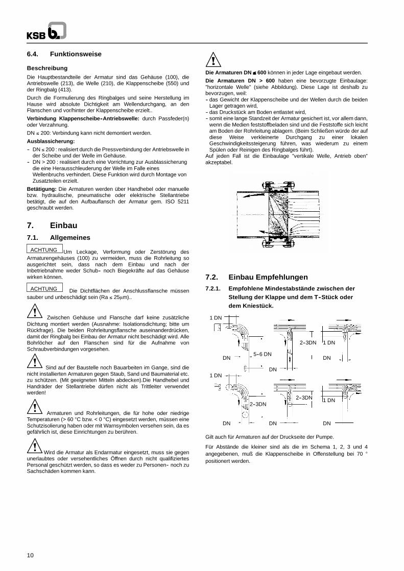
Die Armaturen DN ≤ 600 können in jeder Lage eingebaut werden.
Die Armaturen DN > 600 haben eine bevorzugte Einbaulage:”horizontale Welle” (siehe Abbildung). Diese Lage ist deshalb zubevorzugen, weil:-- das Gewicht der Klappenscheibe und der Wellen durch die beiden
Lager getragen wird,-- das Druckstück am Boden entlastet wird,-- somit eine lange Standzeit der Armatur gesichert ist, vor allem dann,
wenn die Medien feststoffbeladen sind und die Feststoffe sich leichtam Boden der Rohrleitung ablagern. (Beim Schließen würde der aufdiese Weise verkleinerte Durchgang zu einer lokalenGeschwindigkeitssteigerung führen, was wiederum zu einemSpülen oder Reinigen des Ringbalges führt).
Auf jeden Fall ist die Einbaulage ”vertikale Welle, Antrieb oben”akzeptabel.
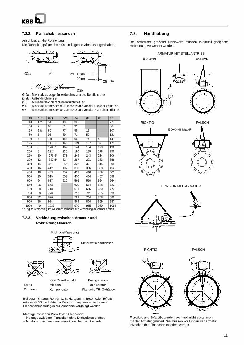
7.2. Einbau Empfehlungen7.2.1. Empfohlene Mindestabstände zwischen der
Stellung der Klappe und dem T--Stück oderdem Kniestück.
DN
1 DN
DNDN
1 DN
DN
2--3DN
DNDN
1 DN
1 DN
2--3DN
5--6 DN
2--3DN
Gilt auch für Armaturen auf der Druckseite der Pumpe.
Für Abstände die kleiner sind als die im Schema 1, 2, 3 und 4angegebenen, muß die Klappenscheibe in Offenstellung bei 70 °positionert werden.
11
7.2.2. Flanschabmessungen
Anschluss an die Rohrleitung.Die Rohrleitungsflansche müssen folgende Abmessungen haben.
Ø2a Ø6 Ø3
Ø5 Ø4
10mm
Ø2b
20mm
Ø 2a : Maximal zulässiger Innendurchmesser des RohrflanschesØ 2b : AußendurchmesserØ 3 : Minimaler RohrflanschinnendurchmesserØ4 : Mindestdurchmesser bei 10mm Abstand von der Flanschdichtfläche.Ø5 : Mindestdurchmesser bei 20mm Abstand von der Flanschdichtfläche.
DN NPS ø2a ø2b ø3 ø4 ø5 ø640 1 ½ 54 49 32 7750 2 63 61 33 8665 2 ½ 80 77 55 13 10780 3 93 89 71 50 121
100 4 116 115 90 74 40 141125 5 141,5 140 119 107 87 171150 6 170,5* 169 144 134 120 196200 8 222* 220 196 189 178 250250 10 276,5* 273 249 243 234 306300 12 327,5* 324 297 291 283 358350 14 361 356 326 321 314 399400 16 412 407 370 366 358 452450 18 463 457 422 416 409 505500 20 515 508 470 464 457 558600 24 617 610 566 560 554 664650 26 668 620 614 608 723700 28 718 671 666 660 773750 30 770 717 711 705 830800 32 820 769 764 758 880900 36 924 869 864 859 987
1000 40 1027 970 965 960 1094* Auf gute Zentrierung des Gehäuses zwischen den Verbindungsschrauben achten.
7.2.3. Verbindung zwischen Armatur undRohrleitungsflansch
RichtigePassung
Metallzwischenflansch
Kein gummibeschichteter
Flansche T5--Gehäuse
Kein Direktkontaktmit demKompensator
KeineDichtung
Bei beschichteten Rohren (z.B. Hartgummi, Beton oder Teflon)müssen KSB die Härte der Beschichtung sowie die genauenFlanschabmessungen zur Abnahme vorgelegt werden.
Montage zwischen Polyethylen Flanschen:-- Montage zwischen Flanschen ohne Dichtleisten erlaubt-- Montage zwischen genuteten Flanschen nicht erlaubt
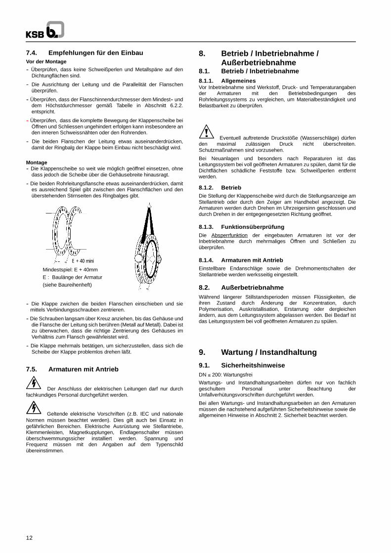
7.3. Handhabung
Bei Armaturen größerer Nennweite müssen eventuell geeigneteHebezeuge verwendet werden.
ARMATUR MIT STELLANTRIEB
RICHTIG FALSCH
HORIZONTALE ARMATUR
RICHTIG FALSCH
BOAX--B Mat--P
RICHTIG FALSCH
Flursäule und Stützüße wurden eventuell nicht zusammenmit der Armatur geliefert. Sie müssen vor Einbau der Armaturzwischen den Flanschen montiert werden.
12
7.4. Empfehlungen für den EinbauVor der Montage
-- Überprüfen, dass keine Schweißperlen und Metallspäne auf denDichtungflächen sind.
-- Die Ausrichtung der Leitung und die Parallelität der Flanschenüberprüfen.
-- Überprüfen, dass der Flanschinnendurchmesser dem Mindest-- unddem Höchstdurchmesser gemäß Tabelle in Abschnitt 6.2.2.entspricht.
-- Überprüfen, dass die komplette Bewegung der Klappenscheibe beiÖffnen und Schliessen ungehindert erfolgen kann insbesondere anden inneren Schweissnähten oder den Rohrenden.
-- Die beiden Flanschen der Leitung etwas auseinanderdrücken,damit der Ringbalg der Klappe beim Einbau nicht beschädigt wird.
Montage-- Die Klappenscheibe so weit wie möglich geöffnel einsetzen, ohne
dass jedoch die Scheibe über die Gehäusebreite hinausragt.
-- Die beiden Rohrleitungsflansche etwas auseinanderdrücken, damites ausreichend Spiel gibt zwischen den Flanschflächen und denüberstehenden Stirnseiten des Ringbalges gibt.
E + 40 mini
E
Mindestspiel: E + 40mmE : Baulänge der Armatur(siehe Baureihenheft)
-- Die Klappe zwichen die beiden Flanschen einschieben und siemittels Verbindungsschrauben zentrieren.
-- Die Schrauben langsam über Kreuz anziehen, bis das Gehäuse unddie Flansche der Leitung sich berühren (Metall auf Metall). Dabei istzu überwachen, dass die richtige Zentrierung des Gehäuses imVerhältnis zum Flansch gewährleistet wird.
-- Die Klappe mehrmals betätigen, um sicherzustellen, dass sich dieScheibe der Klappe problemlos drehen läßt.
7.5. Armaturen mit Antrieb
Der Anschluss der elektrischen Leitungen darf nur durchfachkundiges Personal durchgeführt werden.
Geltende elektrische Vorschriften (z.B. IEC und nationaleNormen müssen beachtet werden). Dies gilt auch bei Einsatz ingefährlichen Bereichen. Elektrische Ausrüstung wie Stellantriebe,Klemmenleisten, Magnetkupplungen, Endlagenschalter müssenüberschwemmungssicher installiert werden. Spannung undFrequenz müssen mit den Angaben auf dem Typenschildübereinstimmen.
8. Betrieb / Inbetriebnahme /Außerbetriebnahme
8.1. Betrieb / Inbetriebnahme8.1.1. AllgemeinesVor Inbetriebnahme sind Werkstoff, Druck- und Temperaturangabender Armaturen mit den Betriebsbedingungen desRohrleitungssystems zu vergleichen, um Materialbeständigkeit undBelastbarkeit zu überprüfen.
Eventuell auftretende Druckstöße (Wasserschläge) dürfenden maximal zulässigen Druck nicht überschreiten.Schutzmaßnahmen sind vorzusehen.
Bei Neuanlagen und besonders nach Reparaturen ist dasLeitungssystem bei voll geöffneten Armaturen zu spülen, damit für dieDichtflächen schädliche Feststoffe bzw. Schweißperlen entferntwerden.
8.1.2. BetriebDie Stellung der Klappenscheibe wird durch die Stellungsanzeige amStellantrieb oder durch den Zeiger am Handhebel angezeigt. DieArmaturen werden durch Drehen im Uhrzeigersinn geschlossen unddurch Drehen in der entgegengesetzten Richtung geöffnet.
8.1.3. FunktionsüberprüfungDie Absperrfunktion der eingebauten Armaturen ist vor derInbetriebnahme durch mehrmaliges Öffnen und Schließen zuüberprüfen.
8.1.4. Armaturen mit AntriebEinstellbare Endanschläge sowie die Drehmomentschalten derStellantriebe werden werksseitig eingestellt.
8.2. AußerbetriebnahmeWährend längerer Stillstandsperioden müssen Flüssigkeiten, dieihren Zustand durch Änderung der Konzentration, durchPolymerisation, Auskristallisation, Erstarrung oder dergleichenändern, aus dem Leitungssystem abgelassen werden. Bei Bedarf istdas Leitungssystem bei voll geöffneten Armaturen zu spülen.
9. Wartung / Instandhaltung
9.1. SicherheitshinweiseDN ≤ 200: Wartungsfrei
Wartungs- und Instandhaltungsarbeiten dürfen nur von fachlichgeschultem Personal unter Beachtung derUnfallverhütungsvorschriften durchgeführt werden.
Bei allen Wartungs- und Instandhaltungsarbeiten an den Armaturenmüssen die nachstehend aufgeführten Sicherheitshinweise sowie dieallgemeinen Hinweise in Abschnitt 2. Sicherheit beachtet werden.
13
9.2. Ausbau der Armatur aus der Rohrleitungund Entkuppeln des Antriebes
Anhand des Typenschildes überprüfen, um welche Armatur essich handelt.
Überprüfen, welches Ersatzteilset benötigt wird.Die Klappenscheibe um 10° öffnen.
Die Armatur muss drucklos sein und, um Verbrennungen zuvermeiden, soweit abgekühlt sein, dass die Temperatur des Mediumsunter 60 °C liegt.
Es besteht Lebensgefahr, wenn eine unter Druck stehendeArmatur geöffnet wird. Bei brennbaren Medien oder Medien, die beiKontakt mit der Feuchtigkeit der Umgebung korrosiv reagieren, mussdie Armatur sorgfältig durchgespült werden. Wenn erforderlich,Sicherheitskleidung und eine Gesichtsschutzmaske tragen. Je nachEinbauposition muss die Armatur vollständig entleert werden.
Vor jedem Transport muss die Armatur sorgfältig entleert unddurchspült werden. Bei Fragen wenden Sie sich bitte an denKSB--Kundendienst.
Beim Ausbau von Stellantrieben, die von einer externenEnergiequelle gespeist werden (elektrisch, hydraulisch,pneumatisch), muss die Energiezufuhr unterbrochen werden.
Ausbau der Armatur und des Stellantriebes aus der Rohrleitung.
Beim Ausbau der Armatur aus der Rohrleitung den Ringbalg nichtbeschädigen. Die Rohrleitungsflansche ausreichendauseinanderdrücken, damit die Armatur leicht entfernt werden kann.
Markieren, wie der Stellantrieb auf die Armatur aufgebaut war.
Stellantrieb entkuppeln. Dabei auf die Verbindungsschraubenachten.
9.3. Ersatzteile,Werkzeugliste, Verbrauchsmaterial9.3.1. ErsatzteileDN ≤ 200: Kein Ersatzteilkit
Es sind die jeweiligen Ersatzteile zu verwenden, die sich imErsatzteilkit Ringbalg, Ersatzteilkit Scheibe und Ersatzteilkit Wellebefinden. Siehe Typenblätter.Alle den Ersatzteilkits entnommenenTeile müssen ersetzt werden.
Bei Einbau und Ausbau der Armatur muss Schritt für Schritt,wie beschrieben, vorgegangen werden, um Verletzungen undMaterialschäden zu vermeiden.Bei Duchführung der Tests sowie demÖffnen und Schließen der Armaturen muss gewährleistet sein, dassder Bediener die Bewegung der Klappenscheibe nicht behindert.
9.3.2. Werkzeugliste für Einbau/AusbauPneumatischer Schraubenautomat, Gabelschlüssel, Ringschlüssel,Steckschlüssel, Schraubenzieher, Hammer, pneumatischesGlätteisen, Keile, Brecheisen und Silikonfett, falls zugelassen.
9.3.3. VerbrauchsmaterialNur das im Kit enthaltene Fett SF verwenden (amlub). DieVerwendung von Maschinenfett ist nicht zulässig!
9.4. Demontage und Zusammenbau derArmatur
9.4.1. Demontage der ArmaturStopfen (916) oder Gehäuseunterteil (176) entfernen; ebenso denSicherungsring (932), falls vorhanden.
Ausblassicherungsschrauben (900.*) und Dichtungshalter (559)entfernen, falls vorhanden.
Antriebswelle (213) und untere Welle (210) herausziehen.
Scheibe (550) herausnehmen und Ringbalg (413) ausbauen.
Darauf achten, dass Scheibenkante, Ringbalg und AnstrichFarb--Beschichtug nicht beschädigt werden.
O--Ringe 412.* unter Verwendung von Silikonfett wechseln. DenRingbalg an den Wellendurchgängen einfetten.
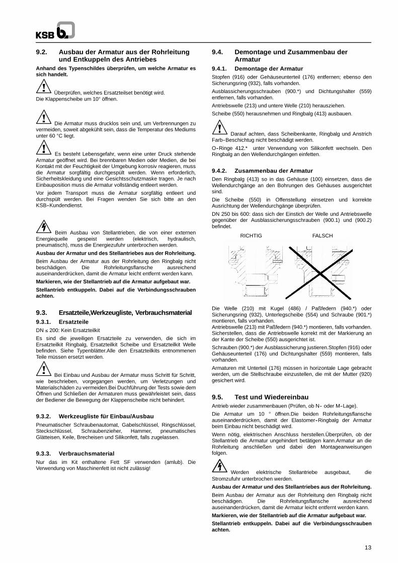
9.4.2. Zusammenbau der ArmaturDen Ringbalg (413) so in das Gehäuse (100) einsetzen, dass dieWellendurchgänge an den Bohrungen des Gehäuses ausgerichtetsind.
Die Scheibe (550) in Offenstellung einsetzen und korrekteAusrichtung der Wellendurchgänge überprüfen.
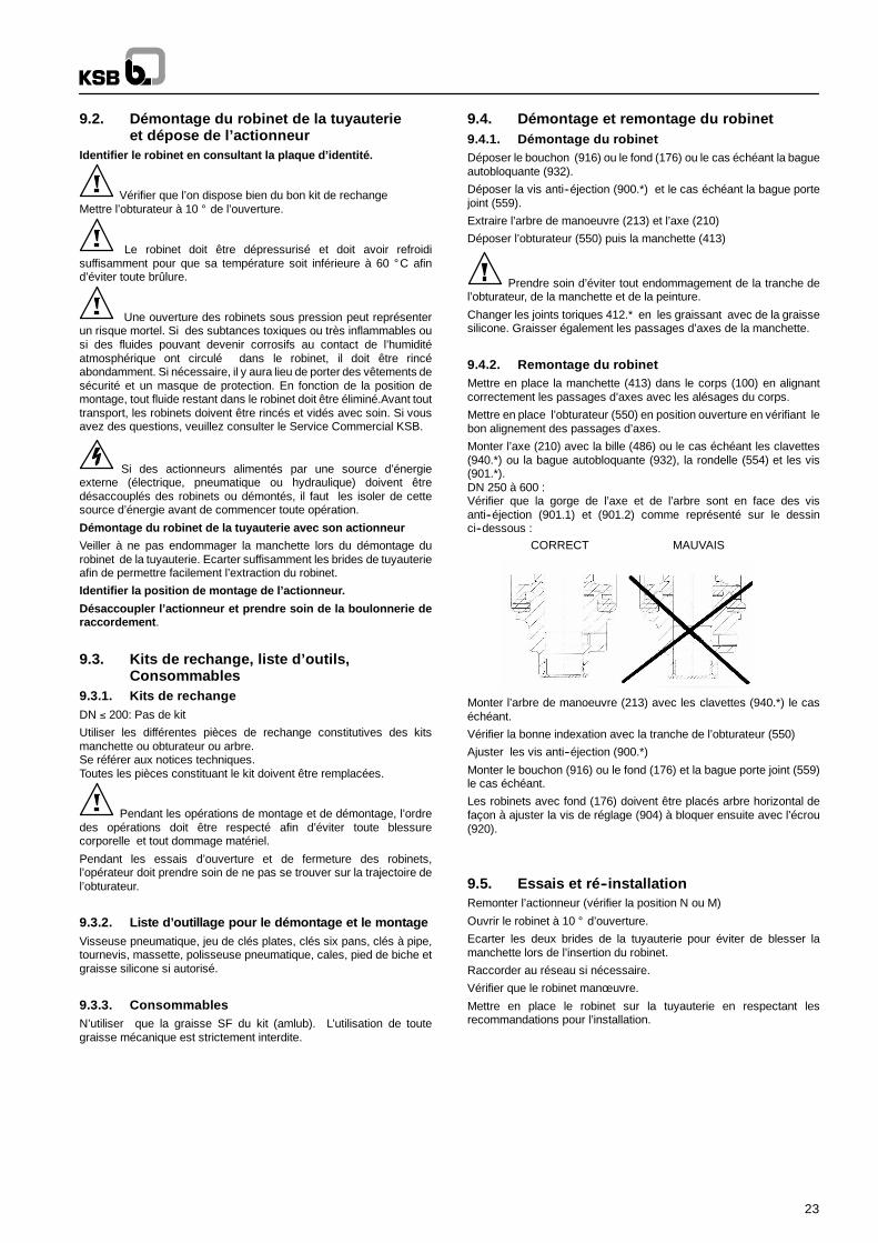
DN 250 bis 600: dass sich der Einstich der Welle und Antriebswellegegenüber der Ausblassicherungsschrauben (900.1) und (900.2)befindet.
RICHTIG FALSCH
Die Welle (210) mit Kugel (486) / Paßfedern (940.*) oderSicherungsring (932), Unterlegscheibe (554) und Schraube (901.*)montieren, falls vorhanden.Antriebswelle (213) mit Paßfedern (940.*) montieren, falls vorhanden.Sicherstellen, dass die Antriebswelle korrekt mit der Markierung ander Kante der Scheibe (550) ausgerichtet ist.
Schrauben (900.*) der Ausblassicherung justieren.Stopfen (916) oderGehäuseunterteil (176) und Dichtungshalter (559) montieren, fallsvorhanden.
Armaturen mit Unterteil (176) müssen in horizontale Lage gebrachtwerden, um die Stellschraube einzustellen, die mit der Mutter (920)gesichert wird.
9.5. Test und WiedereinbauAntrieb wieder zusammenbauen (Prüfen, ob N-- oder M--Lage).
Die Armatur um 10 ° öffnen.Die beiden Rohrleitungsflanscheauseinanderdrücken, damit der Elastomer--Ringbalg der Armaturbeim Einbau nicht beschädigt wird.
Wenn nötig, elektrischen Anschluss herstellen.Überprüfen, ob derStellantrieb die Armatur ungehindert betätigen kann.Armatur an dieRohrleitung anschließen und dabei den Montageanweisungenfolgen.
Werden elektrische Stellantriebe ausgebaut, dieStromzufuhr unterbrochen werden.
Ausbau der Armatur und des Stellantriebes aus der Rohrleitung.
Beim Ausbau der Armatur aus der Rohrleitung den Ringbalg nichtbeschädigen. Die Rohrleitungsflansche ausreichendauseinanderdrücken, damit die Armatur leicht entfernt werden kann.
Markieren, wie der Stellantrieb auf die Armatur aufgebaut war.
Stellantrieb entkuppeln. Dabei auf die Verbindungsschraubenachten.
14
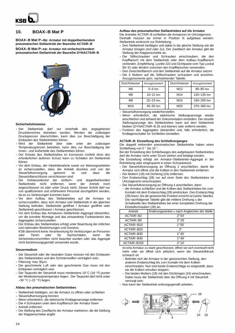
10. BOAX--B Mat P
BOAX--B Mat P--da: Armatur mit doppeltwirkendempneumatischen Stellantrieb der Baureihe ACTAIR--B
BOAX--B Mat P--sa: Armatur mit einfachwirkendempneumatischen Stellantrieb der Baureihe DYNACTAIR--B
Sicherheitshinweise
-- Der Stellantrieb darf nur innerhalb des angegebenenDruckbereiches betrieben werden. Werden die zulässigenDruckgrenzen überschritten, kann dies zur Beschädigung derEinbauten des Stellantriebes führen.
-- Wird der Stellantrieb über oder unter der zulässigenTemperaturgrenzen betrieben, kann dies zur Beschädigung derInnen-- und Außenteile des Stellantriebes führen.
-- Der Einsatz des Stellantriebes im korrosiven Umfeld ohne denerforderlichen äußeren Schutz kann zu Schäden am Stellantriebführen.
-- Vor dem Einbau, der Inbetriebnahme sowie vor Wartungsarbeitenist sicherzustellen, dass der Antrieb drucklos und von derSteuerluftversorgung getrennt ist und dass dieSteuerluftanschlüsse verschlossen sind
-- Die Gehäusedeckel der einfach-- und doppeltwirkendenStellantriebe nicht entfernen, wenn der Antrieb nochangeschlossen ist oder unter Druck steht. Dieser Schritt darf nurvon qualifiziertem und erfahrenem Personal durchgeführt werden,da es zu Verletzungen kommen kann.
-- Vor dem Aufbau des Stellantriebes auf die Armatur istsicherzustellen, dass sich Armatur und Stellantrieb in der gleichenStellung befinden. Stellantrieb geöffnet / Armatur geöffnet oderStellantrieb geschlossen / Armatur geschlossen.
-- Vor dem Einbau das Armaturen--Stellantrieb--Aggregat überprüfen,um die korrekte Montage und das einwandreie Funktionieren desAggregates sicherzustellen.
-- Der Einbau des Stellantriebes erfolgt unter Beachtung der örtlichenund nationalen Bestimmungen und Gesetze.KSB übernimmt keine Verantwortung für Verletzungen an Personenoder Tieren oder für Sachschäden, wenn dieSicherheitsvorschriften nicht beachtet wurden oder das Aggregatnicht bestimmungsgemäß verwendet wurde.
Steuermedium
-- Die Steuerluft oder die neutralen Gase müssen mit den Einbautendes Stellantriebes und den Schmierstoffen verträglich sein.
-- Filterung: max 30µm.-- Die geschmierte Luft oder das geschmierte Gas muss mit den
Einbauten verträglich sein.-- Der Taupunkt der Steuerluft muss mindestens 10° C (18 ° F) punter
der Mindesteinsatztemperatur liegen. Der Taupunkt darf nicht unter--30 ° C (--22 ° F) liegen.
Abbau des pneumatischen Stellantriebes
-- Stellantrieb betätigen, um die Armatur zu öffnen oder schließen-- Steuerluftversorgung trennen-- Wenn erforderlich, die elektrische Endlagenanzeige entfernen-- Die 4 Schrauben unter dem Kopfflansch der Armatur lösen-- Antrieb entfernen-- Die Stellung des Zweiflachs der Armatur markieren, die die Stellung
der Klappenscheibe angibt
Aufbau des pneumatischen Stellantriebes auf die ArmaturDie Antriebe ACTAIR--B schließen die Armaturen im Uhrzeigersinn.Deshalb müssen sie immer in Position N aufgebaut werden:Stellantrieb senkrecht zur Rohrleitung.-- Den Stellantrieb betätigen und dabei in die gleiche Stellung wie die
Armatur bringen (Auf oder Zu). Der Zweiflach der Armatur gibt dieStellung der Klappenscheibe an.
-- Die Stiftschrauben und Schrauben einschrauben, die denKopfflansch mit dem Stellantrieb oder dem Aufbau--Kopfflanschverbinden. Empfehlung: Loctite 222 und Dichtpaste vom Typ Loxéal58--31 oder ähnlich zwischen den Kopfflanschen verwenden.
-- Den Zwischenflansch und den Stellantrieb auf die Armatur setzen-- Die 4 Muttern auf die Stiftschrauben schrauben und anziehen.
Anzugsmomente gem. nachstehender Tabelle:
Durchmesser Anzugsmoment Durchmesser Anzugsmoment
M5 5--6 Nm M12 80--85 Nm
M6 10--11 Nm M14 125--135 Nm
M8 20--23 Nm M16 190--200 Nm
M10 45--50 Nm M20 370--390 Nm
-- Steuerluftversorgung wiederherstellen.-- Wenn erforderlich, die elektrische Stellungsanzeige wieder
anschließen und anhand der Dokumentation einstellen. Die visuelleStellungsanzeige des Stellantriebes kann auf dem Stellantriebbleiben (DYNACTAIR--B 25 und kleiner) oder entfernt werden.
-- Funktion des Aggregates überprüfen und, falls erforderlich, dieEndlagenschalter für Schließen einstellen.
ACTAIR--B: Einstellung des SchließvorgangesDie doppelt wirkenden pneumatischen Stellantriebe haben einenSchließweg von 0 ° bis 10 ° .Bei der Einstellung des Schließweges des aufgebauten Stellantriebesdarf die Armatur nicht unter Druck stehen und betätigt werden.Die Einstellung erfolgt am Armatur--Stellantrieb--Aggregat in derRohrleitung oder eingespannt in einen Schraubstock.-- Die Steuerluftversorgung an Öffnung 2 anschließen, damit die
Armatur sich öffnet und die Kolben in den Stellantrieb einfahren.-- Die Muttern (18) mit Dichtring (24) entfernen.-- Den Endanschlag (28) nur auf einer Seite des Stellantriebes im
Uhrzeigersinn einschrauben.-- Die Steuerluftversorgung an Öffnung 4 anschließen, dann:
-- die Armatur schließen und die Kolben des Stellantriebes bis zumKontakt mit dem Endanschlag (28) eindrücken. Den Endanschlag(28) lösen, bis die gewünschte Position erreicht ist (siehe Tabelle).Die nachfolgende Tabelle gibt die mittlere Drehung α derSchaltwelle des Stellantriebes bei einer kompletten Drehung derEinstellschrauben (28) an.
Antrieb Änderungswinkel α nach Angleichen der WelleACTAIR--B2 2° 54’ACTAIR--B5 2° 18’ACTAIR--B10 1° 55’ACTAIR--B20 2°ACTAIR--B30 1° 45’ACTAIR--B40 1° 49’ACTAIR--B150 2° 14’
Ist eine Armatur zu stark geschlossen, öffnet sie sich eventuell nichtmehr oder sie öffnet sich plötzlich, wenn der Steuerluftdruckschwach ist.-- Befindet sich die Armatur in der gewünschten Stellung, den
anderen Endanschlag bis zum Kontakt mit dem Kolbeneinschrauben. Nun sind beide Endanschläge so eingestellt, dasssie die Kolben simultan stoppen.
-- Die beiden Muttern (18) mit den Dichtringen (24) einschrauben.Dabei muss der Stellantrieb über die Öffnung 4 mit Steuerluftversorgt sein.
-- Nun kann der Stellantrieb ordnungsgemäß arbeiten.
2 4
28
24 18
15
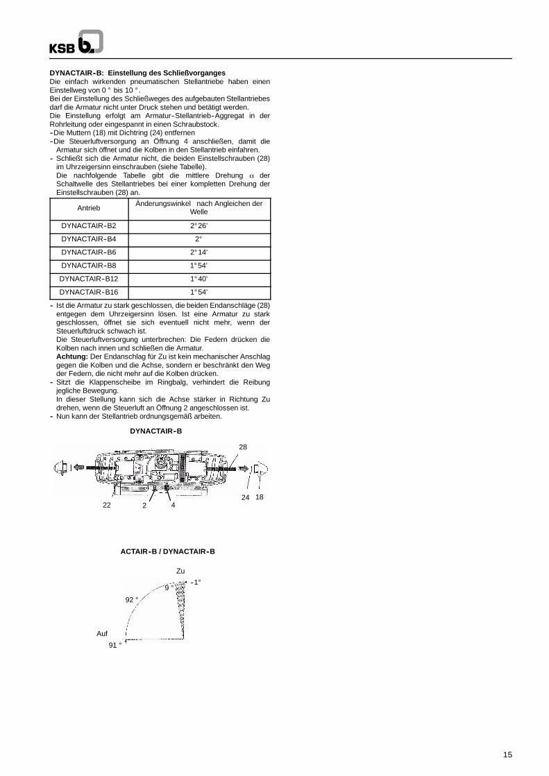
DYNACTAIR--B: Einstellung des SchließvorgangesDie einfach wirkenden pneumatischen Stellantriebe haben einenEinstellweg von 0 ° bis 10 ° .Bei der Einstellung des Schließweges des aufgebauten Stellantriebesdarf die Armatur nicht unter Druck stehen und betätigt werden.Die Einstellung erfolgt am Armatur--Stellantrieb--Aggregat in derRohrleitung oder eingespannt in einen Schraubstock.--Die Muttern (18) mit Dichtring (24) entfernen--Die Steuerluftversorgung an Öffnung 4 anschließen, damit die
Armatur sich öffnet und die Kolben in den Stellantrieb einfahren.-- Schließt sich die Armatur nicht, die beiden Einstellschrauben (28)
im Uhrzeigersinn einschrauben (siehe Tabelle).Die nachfolgende Tabelle gibt die mittlere Drehung α derSchaltwelle des Stellantriebes bei einer kompletten Drehung derEinstellschrauben (28) an.
AntriebÄnderungswinkel nach Angleichen der
Welle
DYNACTAIR--B2 2° 26’
DYNACTAIR--B4 2°
DYNACTAIR--B6 2° 14’
DYNACTAIR--B8 1° 54’
DYNACTAIR--B12 1° 40’
DYNACTAIR--B16 1° 54’
-- Ist die Armatur zu stark geschlossen, die beiden Endanschläge (28)entgegen dem Uhrzeigersinn lösen. Ist eine Armatur zu starkgeschlossen, öffnet sie sich eventuell nicht mehr, wenn derSteuerluftdruck schwach ist.Die Steuerluftversorgung unterbrechen: Die Federn drücken dieKolben nach innen und schließen die Armatur.Achtung: Der Endanschlag für Zu ist kein mechanischer Anschlaggegen die Kolben und die Achse, sondern er beschränkt den Wegder Federn, die nicht mehr auf die Kolben drücken.
-- Sitzt die Klappenscheibe im Ringbalg, verhindert die Reibungjegliche Bewegung.In dieser Stellung kann sich die Achse stärker in Richtung Zudrehen, wenn die Steuerluft an Öffnung 2 angeschlossen ist.
-- Nun kann der Stellantrieb ordnungsgemäß arbeiten.
424 18
28
22
DYNACTAIR--B
--1°9 °
92 °
91 °
Auf
Zu
ACTAIR--B / DYNACTAIR--B
2
16
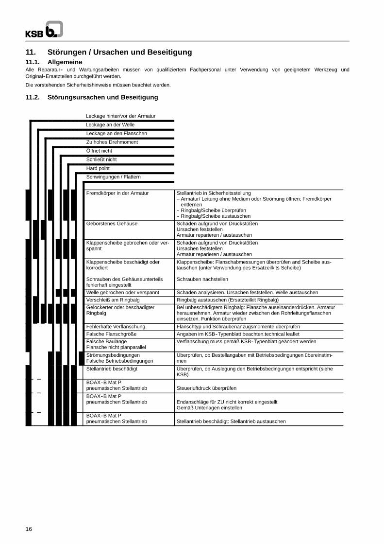
11. Störungen / Ursachen und Beseitigung11.1. AllgemeineAlle Reparatur-- und Wartungsarbeiten müssen von qualifiziertem Fachpersonal unter Verwendung von geeignetem Werkzeug undOriginal--Ersatzteilen durchgeführt werden.
Die vorstehenden Sicherheitshinweise müssen beachtet werden.
11.2. Störungsursachen und Beseitigung
Leckage hinter/vor der Armatur
Leckage an der Welle
Leckage an den Flanschen
Zu hohes Drehmoment
Öffnet nicht
Schließt nicht
Hard point
Schwingungen / Flattern
Fremdkörper in der Armatur Stellantrieb in Sicherheitsstellung– Armatur/ Leitung ohne Medium oder Strömung öffnen; Fremdkörper
entfernen-- Ringbalg/Scheibe überprüfen-- Ringbalg/Scheibe austauschen
Geborstenes Gehäuse Schaden aufgrund von DruckstößenUrsachen feststellenArmatur reparieren / austauschen
Klappenscheibe gebrochen oder ver-spannt
Schaden aufgrund von DruckstößenUrsachen feststellenArmatur reparieren / austauschen
Klappenscheibe beschädigt oderkorrodiert
Schrauben des Gehäuseunterteilsfehlerhaft eingestellt
Klappenscheibe: Flanschabmessungen überprüfen and Scheibe aus-tauschen (unter Verwendung des Ersatzeilkits Scheibe)
Schrauben nachstellen
Welle gebrochen oder verspannt Schaden analysieren. Ursachen feststellen. Welle austauschenVerschleiß am Ringbalg Ringbalg austauschen (Ersatzteilkit Ringbalg)Gelockerter oder beschädigterRingbalg
Bei unbeschädigtem Ringbalg: Flansche auseinanderdrücken. Armaturherausnehmen. Armatur wieder zwischen den Rohrleitungsflanscheneinsetzen. Funktion überprüfen
Fehlerhafte Verflanschung Flanschtyp und Schraubenanzugsmomente überprüfenFalsche Flanschgröße Angaben im KSB--Typenblatt beachten.technical leafletFalsche BaulängeFlansche nicht planparallel
Verflanschung muss gemäß KSB--Typenblatt geändert werden
StrömungsbedingungenFalsche Betriebsbedingungen
Überprüfen, ob Bestellangaben mit Betriebsbedingungen übereinstim-men
Stellantrieb beschädigt Überprüfen, ob Auslegung den Betriebsbedingungen entspricht (sieheKSB)
BOAX--B Mat Ppneumatischen Stellantrieb Steuerluftdruck überprüfen
BOAX--B Mat Ppneumatischen Stellantrieb Endanschläge für ZU nicht korrekt eingestellt
Gemäß Unterlagen einstellen
BOAX--B Mat Ppneumatischen Stellantrieb Stellantrieb beschädigt: Stellantrieb austauschen
17
3. GénéralitésCes instructions de fonctionnement s’appliquent aux robinets à papilloncentré à étanchéité élastomère KSB (se reporter au paragraphe 5).
La conception, la fabrication et les contrôles des robinets KSB sont soumisà un Système d’Assurance Qualité conforme à la norme EN ISO 9001 et àla Directive des Equipements Sous Pression 97/23/CE (DESP).
Dans une configuration de robinet avec actionneur, autre que manuel, lesous ensemble ainsi constitué peut répondre aux exigences de la directivemachine 2006/42/EC en tant que quasi machine dans l’acceptation de ladirective.
Une installation correcte est nécessaire pour assurer un bonfonctionnement de ces robinets.
Le fabricant ne peut être considéré comme responsable du mauvaisfonctionnement de ces robinets si les instructions de service ne sontpas respectées.
ATTENTION Le fonctionnement des robinets en dehors de la plagede fonctionnement admissible n’est pas autorisé. Les limites sontstipulées sur la plaque signalétique ou dans la notice descriptive. Lesvaleurs indiquées dans les tableaux de pressions et de températuresne doivent pas être dépassées. Toute utilisation en dehors des limitesspécifiées causerait une surcharge des robinets qu’ils ne pourraientsupporter.
Les notices descriptives peuvent être consultées dans notrecatalogue Produits sur Internet à l’adresse www.ksb.com
Le non--respect de cette règle est susceptible de causer desdommages et blessures tant au personnel qu’aux installations :-- Blessures dues aux fuites de liquide (froid/chaud, inflammable ou
sous--pression)-- Fonctionnement incorrect ou destruction du robinet.
Les descriptions et instructions reprises dans cette notice serapportent aux versions standard, mais également aux versionsspéciales s’y rapportant.
Ces instructions de service ne tiennent pas compte :-- des incidents pouvant se produire pendant la mise en place et le
fonctionnement.-- des règles de sécurité locales. L’utilisateur a la responsabilité de
s’assurer que ces règles sont appliquées et il en est de même pourles équipes de montage impliquées.
Pour les robinets motorisés, les paramètres de raccordementspécifié, les instructions d’installation et la notice d’instructions deservice de l’actionneur doivent être respectés.
ATTENTION La manipulation de ces robinets nécessitent unpersonnel expérimenté et qualifié.
Le personnel responsable du fonctionnement et de l’installation durobinet se doit de connaître l’interaction entre le robinet et l’ensembledans lequel il se trouve.
Des erreurs concernant le robinet de la part de l’opérateur peuventavoir des conséquences graves sur la marche de l’usine, par exemple :-- fuite de produit-- perte de production usine/machine-- effets contraires réduction ou augmentation du rendement par
rapport à usine/machine.Pour toutes autres questions ou en cas de dommages au robinet,veuillez prendre contact avec l’Agence Commerciale KSB.
Pour toutes autres questions et commandes supplémentaires,veuillez spécifier toutes les indications inscrites sur la plaqued’identité.
Les spécifications (conditions de fonctionnement) des robinets sontreprises dans cette notice ainsi que dans la notice technique durobinet concerné (se reporter au paragraphe 5).
En cas de retour du robinet au fabricant, veuillez vous référer auparagraphe 4.
4. SécuritéCette notice contient des instructions de base à respecter pour lefonctionnement. Il est donc vital pour le monteur et l’opérateur de lirecette notice avant de procéder à l’installation et la mise en route durobinet. De même, cette notice doit toujours être disponible sur le siteoù le robinet est monté.
ll ne suffit pas de respecter les instructions générales reprises auparagraphe ”sécurité”, il faut également respecter celles donnéesdans les autres paragraphes.
4.1. Symboles de sécurité utilisés dans lesinstructions de fonctionnement
Les instructions de sécurité énoncées dans cette notice d’instructionsqui seraient à même de par leur non--respect de causer des dommagescorporels sont spécialement marquées par le symbole de risque :
conforme à la norme ISO 3864--B.3.1.ou par le symbole d’avertissement tension électrique :
conforme à la norme ISO 3864--B.3.6.
Les instructions qui pourraient impliquer des risques au robinet etmettre en cause son fonctionnement en cas de non--observation, sontrepérées par le mot
ATTENTIONLes indications directement attachées au robinet même (telle que parexemple pression nominale) doivent être respectées et maintenueslisibles.
4.2. Qualification et formation du personnelLe personnel affecté au fonctionnement, à l’inspection et à l’installation doit être parfaitement qualifié pour le travailcorrespondant. Les responsabilités, compétences et encadrement dupersonnel doivent être clairement définies par l’utilisateur. Si lepersonnel en question ne possède pas les connaissances requises,une formation doit alors lui être proposée. Si jugé nécessaire, lefabricant/fournisseur fournira une telle formation et instructions à lademande de l’utilisateur. De plus, l’utilisateur a la responsabilité des’assurer que ces dites instructions sont bien comprises par lepersonnel en question.
4.3. Dangers en cas de non--respect desinstructions de sécurité
Le non--respect des instructions de sécurité peut causer desdommages corporels au personnel, des dangers pourl’environnement et pour le matériel lui--même. Ce non--respect auraégalement pour conséquence l’annulation pure et simple de lagarantie.
Cela pourrait par exemple aboutir :-- à la non--obtention des fonctions essentielles robinet/usine-- à des résultats non satisfaisants des procédures d’entretien et
réparations prescrites-- à des dangers pour l’environnement suite à des fuites de matières
dangereuses4.4. Sensibilisation à la sécuritéLes instructions de sécurité contenues dans cette notice, l’applicationdes Règles Nationales pour la Prévention des Accidents ainsi quetoutes autres règles propres à l’utilisateur applicables au travailinterne, fonctionnement ou sécurité doivent être prises en compte.
4.5. Instructions de sécuritéutilisateur/opérateur
Toute partie chaude ou froide du robinet (corps ou poignée ouactionneur) qui pourrait créer un risque de danger doit être protégéepar l’utilisateur contre des contacts accidentels.Toute fuite de matière dangereuse (par exemple inflammable ouchaude) doit être éliminer pour éviter tout danger pour les personnesou pour l’environnement. La législation s’y référant doit êtrestrictement respectée.
Tout risque d’accident électrique doit être efficacementmaîtrisé. (Pour les détails, veuillez vous référer à la norme IEC 364 ouaux normes nationales équivalentes et/ou aux réglements locaux surl’alimentation éléctrique).
18
4.6. lnstructions de sécurité pour les travauxd’inspection et d’installation
4.6.1 GénéralitésSur un robinet actionné, les instructions de cette présente noticed’instructions ainsi que celles indiquées dans les notices d’instructionde l’actionneur, du positionneur et/ou appareil de régulation doiventêtre strictement suivies.
L’utilisateur a la responsabilité de s’assurer que les travauxd’inspection et d’installation soient réalisés par du personnel autorisé,d’une qualification adéquate qui est familiarisé avec cette noticed’instructions.
Tout travail sur un robinet ne peut être effectué que s’il est horspression et que sa température a été ramenée à 60 ° C maximum.
Toute intervention sur des robinets motorisés ne peut être effectuéqu’après déconnexion de la source d’énergie. La procédure décritedans les instructions de service pour la mise en arrêt de l’actionneurdoit être respectée.
Les robinets en contact avec des matières dangereuses doivent êtredécontaminés. Immédiatement après l’achèvement du travail, tousles équipements de sécurité doivent être réinstallés et/ou redémarrés.
Avant toute remise en service, veuiller vous référer aux différentspoints du paragraphe 7.
4.6.2. Montage bout de ligne et démontage avalLes robinets BOAX--B Types 2, 4 et 5 se montent entre brides, partirants, sans joints de bride.Utilisation en montage bout de ligne et démontage aval à latempérature ambiante des robinets de fabrication standard :
Gaz ouDangereux** Tous DN : non autorisé
Gaz ouliquides* Non dangereux
**DN ≤ 200: ∆PS = 10 bar max.DN 250 à 500: ∆PS = 7 bar max.
Liquides*Dangereux**
DN ≤ 200: ∆PS = 10 bar max.DN > 200: ∆PS = 7 bar max.
Liquides*Non dangereux
**DN ≤ 200: ∆PS = 10 bar max.DN > 200: ∆PS = 7 bar max.
∆PS: Pression différentielle
* Sont considérés comme liquides, les fluides dont la pression devapeur à la température maximale admissible est inférieure ouégale à 0,5 bar au dessus de la pression atmosphérique normale(1013 mbar).
** Fluide dangereux et non dangereux selon la classification de laDESP.
NOTA : Un robinet monté au bout d’une tuyauterie avec unecontre--bride pleine à l’aval n’est pas à considérer commemontage bout de ligne.
4.7. Modification non autoriséeLes équipements ne doivent subir ni changements, ni modificationssans avoir prélablement consulté le fabricant. Le fabricant ne pourrapas être jugé responsable des dégats occasionnés par l’utilisation depièces ou accessoires n’étant pas d’origine.
4.8. Modes de fonctionnement non autorisésLa sécurité opérationnelle et la fiabilité du robinet fourni ne sontgaranties que dans la limite d’utilisation tel que définie dans la section2 ”Généralités”de la notice instructions.
Les limites indiquées dans la notice technique ne doivent êtredépassées en aucun cas.
5. Transport et stockage intermédiaire5.1. TransportLes robinets sont livrés prêts à l’utilisation.
ATTENTION Pour le transport et le stockage, les robinets doiventêtre maintenus en position semi--fermée et être emballés dans descaisses carton.
ATTENTION Pour éviter tout dommage, ne pas élinguer le robinetpar le col, volant ou l’actionneur.
Après livraison ou avant l’installation, il est nécessaire de vérifier lerobinet afin de détecter des dommages éventuels suite au transport.
5.2. Stockage intermédiaireLes robinets doivent être stockés de façon à fonctionner correctementmême après un stockage prolongé. Ceci inclut :-- Stockage à 5 ° de la position fermée-- Précautions particulières contre la contamination, le gel et la
corrosion.
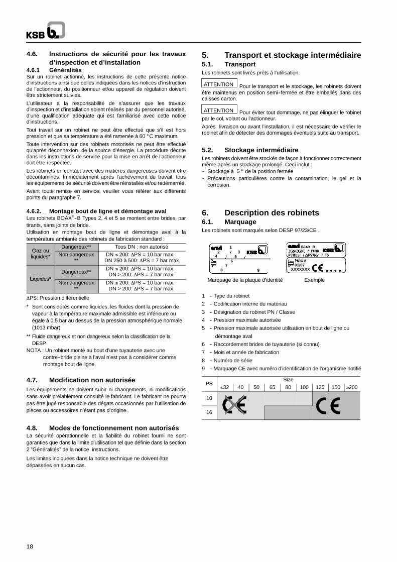
6. Description des robinets6.1. MarquageLes robinets sont marqués selon DESP 97/23/CE .
Marquage de la plaque d’identité Exemple
01/07XXXXXXX
12 3
4 56
78 9
1 -- Type du robinet
2 -- Codification interne du matériau
3 -- Désignation du robinet PN / Classe
4 -- Pression maximale autorisée
5 -- Pression maximale autorisée utilisation en bout de ligne ou
démontage aval
6 -- Raccordement brides de tuyauterie (si connu)
7 -- Mois et année de fabrication
8 -- Numéro de série
9 -- Marquage CE avec numéro d’identification de l’organisme notifié
PSSize
PS≤32 40 50 65 80 100 125 150 ≥200
10
16
19
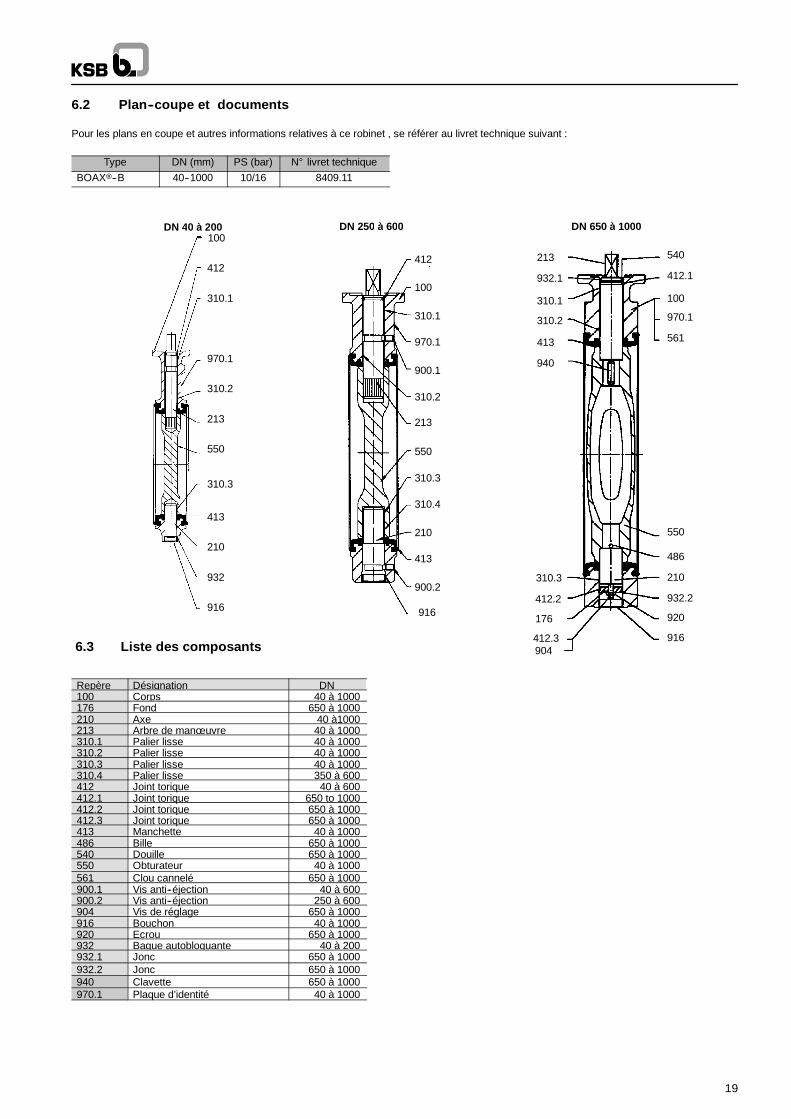
6.2 Plan--coupe et documents
Pour les plans en coupe et autres informations relatives à ce robinet , se référer au livret technique suivant :
Type DN (mm) PS (bar) N° livret techniqueBOAX--B 40--1000 10/16 8409.11
100
412
310.1
970.1
310.2
213
550
310.3
413
210
916
100
412
310.1
900.1
970.1
310.2
213
550
310.3
413
210
916
310.4
900.2
DN 250 à 600 DN 650 à 1000
932.1
100
940
412.2
213
550
210
561
540
310.1
413
412.1
970.1
176
310.2
920
310.3
932.2
486
916
932
DN 40 à 200
6.3 Liste des composants 904412.3
Repère Désignation DN100 Corps 40 à 1000176 Fond 650 à 1000210 Axe 40 à1000213 Arbre de manœ uvre 40 à 1000310.1 Palier lisse 40 à 1000310.2 Palier lisse 40 à 1000310.3 Palier lisse 40 à 1000310.4 Palier lisse 350 à 600412 Joint torique 40 à 600412.1 Joint torique 650 to 1000412.2 Joint torique 650 à 1000412.3 Joint torique 650 à 1000413 Manchette 40 à 1000486 Bille 650 à 1000540 Douille 650 à 1000550 Obturateur 40 à 1000561 Clou cannelé 650 à 1000900.1 Vis anti--éjection 40 à 600900.2 Vis anti--éjection 250 à 600904 Vis de réglage 650 à 1000916 Bouchon 40 à 1000920 Ecrou 650 à 1000932 Bague autobloquante 40 à 200932.1 Jonc 650 à 1000932.2 Jonc 650 à 1000940 Clavette 650 à 1000970.1 Plaque d’identité 40 à 1000
20
6.4. Principe de fonctionnementDescriptionUn robinet est constitué principalement d’un corps (100), d’un arbrede manoeuvre (213), d’un axe inférieur (210), d’un obturateur (550) etd’une manchette élastomère (413).
Le savoir--faire découlant de la formulation et fabrication de lamanchette élastomère assure une étanchéite parfaite au niveau despassages d’axes, aux brides et au sectionnement amont/aval.
Liaison arbre/obturateur : L’obturateur (550) est lié à l’arbre demanoeuvre au moyen de clavette(s) ou cannelures.DN ≤ 200 : Cette liaison est indémontable
Anti--éjection :-- DN ≤ 200 : réalisée par l’emmanchement serré de l’arbre dans
l’obturateur et de l’axe dans le corps-- DN > 200 : réalisée par un dispositif anti--éjection qui évite la
projection de l’arbre hors du corps en cas de rupture d’arbre.La fonction est réalisée par des pièces complémentaires.
Manœ uvre : Les robinets sont manœ uvrés par des poignées ouactionneurs quart de tour manuels ou des actionneurs électriques,pneumatiques ou hydrauliques montés sur l’embase des robinetssuivant la norme ISO 5211.
7. Installation7.1. Généralités
ATTENTION Pour éviter toute fuite, déformation ou rupture ducorps, la tuyauterie doit être correctement alignée de telle sortequ’aucune poussée ou effort de flexion parasites n’agissent sur lescorps des robinets quand ils sont installés et en service.
ATTENTION Les faces d’étanchéité des brides doivent êtrepropres et non endommagées (Ra ≤ 25µm).
Il est interdit de rajouter un joint (excepté un joint d’isolationélectrique, nous consulter) entre le corps et les brides de la tuyauterie.Ecarter les deux brides de la tuyauterie pour éviter de blesser lamanchette lors de l’insertion du robinet. Tous les trous des bridesdoivent être utilisés pour le bridage.
Sur une installation en cours de montage, les robinets nonmontés doivent être protégés de la poussière, du sable et desmatériaux de construction etc... (couvrir avec des moyens adéquats).Ne pas utiliser les poignées et les volants d’actionneurs commemarchepieds !
Les robinets et les tuyauteries utilisés en haute (> 60 ° C) oubasse (< 0 ° C) température doivent être soit équipés d’une isolationde protection soit équipés des symboles de prévention indiquant qu’ilest dangereux de toucher ces robinets.
Si un robinet est utilisé en bout de ligne, il doit être protégé detout risque d’ouverture accidentelle ou par des personnes nonautorisées de façon à éviter tout risque de dommage pour lepersonnel et les installations.
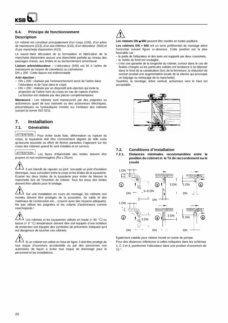
Les robinets DN ≤ 600 peuvent être montés en toutes positions.
Les robinets DN > 600 ont un sens préférentiel de montage arbrehorizontal suivant figure ci--dessous. Cette position est la plusfavorable car :-- le poids de l’obturateur et des axes est supporté par deux coussinets,-- la butée du fond est soulagée,-- c’est une garantie de la longévité du robinet, surtout dans le cas de
fluides chargés où les particules solides ont tendance à se déposerdans le fond de la canalisation (lors de la fermeture, la réduction desection produit une augmentation locale de la vitesse qui provoqueun balyage ou nettoyage de la manchette).
Toutefois, le montage, arbre vertical, actionneur vers le haut estacceptable.
7.2. Conditions d’installation7.2.1. Distances minimales recommandées entre la
position du robinet et le Té de raccordement ou lecoude
DN
1 DN
DNDN
1 DN
DN
3 DN
DNDN
1 DN
1 DN
3 DN
5--6 DN
3 DN1 3 5
642
Egalement valable pour robinet monté en sortie de pompe.Pour des distances inférieures à celles indiquées dans les schémas1, 2, 3 et 4, positionner l’obturateur dans une position d’ouverture de70 ° .
21
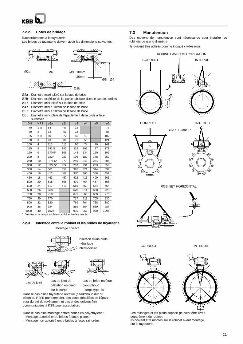
7.2.2. Cotes de bridage
Raccordements à la tuyauterie.Les brides de tuyauterie doivent avoir les dimensions suivantes :
Ø2a Ø6 Ø3
Ø5 Ø4
10mm
Ø2b
20mm
Ø2a : Diamètre maxi toléré sur la face de brideØ2b : Diamètre extérieur de la partie tubulaire dans le cas des colletsØ3 : Diamètre mini toléré sur la face de brideØ4 : Diamètre mini à 10mm de la face de brideØ5 : Diamètre mini à 20mm de la face de brideØ6 : Diamètre mini toléré de l’épaulement de la bride à face
surélevéeDN NPS ø2a ø2b ø3 ø4 ø5 ø640 1 ½ 54 49 32 7750 2 63 61 33 8665 2 ½ 80 77 55 13 10780 3 93 89 71 50 121
100 4 116 115 90 74 40 141125 5 141,5 140 119 107 87 171150 6 170,5* 169 144 134 120 196200 8 222* 220 196 189 178 250250 10 276,5* 273 249 243 234 306300 12 327,5* 324 297 291 283 358350 14 361 356 326 321 314 399400 16 412 407 370 366 358 452450 18 463 457 422 416 409 505500 20 515 508 470 464 457 558600 24 617 610 566 560 554 664650 26 668 620 614 608 723700 28 718 671 666 660 773750 30 770 717 711 705 830800 32 820 769 764 758 880900 36 924 869 864 859 987
1000 40 1027 970 965 960 1094* Vérifier si le corps est bien centré entre les tirants
7.2.3 Interface entre le robinet et les brides de tuyauterieMontage correct
Insertion d’une bridemétalliqueintermédiaire
pas de bride revêtuecaoutchouc
corps type T5
pas de joint dedilatation en directsur le corps
pas de joint
Dans le cas d’une tuyauterie revêtue (caoutchouc dur oubéton ou PTFE par exemple), des cotes détaillées de l’épais-seur dureté du revêtement et des brides doivent êtrecommuniquées à KSB pour acceptation.
Dans le cas d’un montage entres brides en polyéthylène :-- Montage autorisé entre brides à faces planes-- Montage non autorisé entre brides à faces rainurées.
7.3 ManutentionDes moyens de manutention sont nécessaires pour installer lesrobinets de grand diamètre.
Ils doivent être utilisés comme indiqué ci--dessous.
ROBINET AVEC MOTORISATION
CORRECT INTERDIT
ROBINET HORIZONTAL
CORRECT INTERDIT
BOAX--B Mat--P
CORRECT INTERDIT
Les rallonges et les pieds support peuvent être livrésséparément du robinet.Ils doivent être montés sur le robinet avant montagesur la tuyauterie.
22
7.4. Recommandations pour l’installationAvant assemblage
-- Vérifier l’absence de gouttes de soudure et copeaux métalliques surles portées de joint.
-- Vérifier l’alignement des conduites et le parallélisme des brides.
-- Vérifier que le diamètre intérieur des brides soit en accord avec lesdiamètres minimum et maximum définis par le fabricant.
-- Vérifier que rien ne gêne le débattement de l’obturateur lors del’ouverture ou la fermeture, en particulier au niveau des souduresinternes ou des extrémités de tuyauterie.
-- Ecarter les deux brides de la tuyauterie pour éviter de blesser lamanchette lors de l’insertion du robinet.
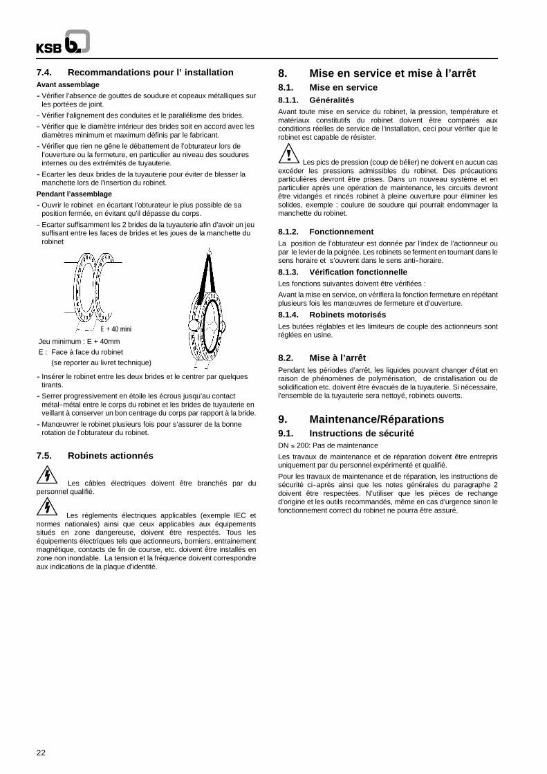
Pendant l’assemblage
-- Ouvrir le robinet en écartant l’obturateur le plus possible de saposition fermée, en évitant qu’il dépasse du corps.
-- Ecarter suffisamment les 2 brides de la tuyauterie afin d’avoir un jeusuffisant entre les faces de brides et les joues de la manchette durobinet
E + 40 mini
E
Jeu minimum : E + 40mmE : Face à face du robinet
(se reporter au livret technique)
-- Insérer le robinet entre les deux brides et le centrer par quelquestirants.
-- Serrer progressivement en étoile les écrous jusqu’au contactmétal--métal entre le corps du robinet et les brides de tuyauterie enveillant à conserver un bon centrage du corps par rapport à la bride.
-- Manœ uvrer le robinet plusieurs fois pour s’assurer de la bonnerotation de l’obturateur du robinet.
7.5. Robinets actionnés
Les câbles électriques doivent être branchés par dupersonnel qualifié.
Les règlements électriques applicables (exemple IEC etnormes nationales) ainsi que ceux applicables aux équipementssitués en zone dangereuse, doivent être respectés. Tous leséquipements électriques tels que actionneurs, borniers, entrainementmagnétique, contacts de fin de course, etc. doivent être installés enzone non inondable. La tension et la fréquence doivent correspondreaux indications de la plaque d’identité.
8. Mise en service et mise à l’arrêt8.1. Mise en service8.1.1. GénéralitésAvant toute mise en service du robinet, la pression, température etmatériaux constitutifs du robinet doivent être comparés auxconditions réelles de service de l’installation, ceci pour vérifier que lerobinet est capable de résister.
Les pics de pression (coup de bélier) ne doivent en aucun casexcéder les pressions admissibles du robinet. Des précautionsparticulières devront être prises. Dans un nouveau système et enparticulier après une opération de maintenance, les circuits devrontêtre vidangés et rincés robinet à pleine ouverture pour éliminer lessolides, exemple : coulure de soudure qui pourrait endommager lamanchette du robinet.
8.1.2. FonctionnementLa position de l’obturateur est donnée par l’index de l’actionneur oupar le levier de la poignée. Les robinets se ferment en tournant dans lesens horaire et s’ouvrent dans le sens anti--horaire.
8.1.3. Vérification fonctionnelleLes fonctions suivantes doivent être vérifiées :
Avant la mise en service, on vérifiera la fonction fermeture en répétantplusieurs fois les manœ uvres de fermeture et d’ouverture.
8.1.4. Robinets motorisésLes butées réglables et les limiteurs de couple des actionneurs sontréglées en usine.
8.2. Mise à l’arrêtPendant les périodes d’arrêt, les liquides pouvant changer d’état enraison de phénomènes de polymérisation, de cristallisation ou desolidification etc. doivent être évacués de la tuyauterie. Si nécessaire,l’ensemble de la tuyauterie sera nettoyé, robinets ouverts.
9. Maintenance/Réparations9.1. Instructions de sécuritéDN ≤ 200: Pas de maintenance
Les travaux de maintenance et de réparation doivent être entreprisuniquement par du personnel expérimenté et qualifié.
Pour les travaux de maintenance et de réparation, les instructions desécurité ci--après ainsi que les notes générales du paragraphe 2doivent être respectées. N’utiliser que les pièces de rechanged’origine et les outils recommandés, même en cas d’urgence sinon lefonctionnement correct du robinet ne pourra être assuré.
23
9.2. Démontage du robinet de la tuyauterieet dépose de l’actionneur
Identifier le robinet en consultant la plaque d’identité.
Vérifier que l’on dispose bien du bon kit de rechangeMettre l’obturateur à 10 ° de l’ouverture.
Le robinet doit être dépressurisé et doit avoir refroidisuffisamment pour que sa température soit inférieure à 60 ° C afind’éviter toute brûlure.
Une ouverture des robinets sous pression peut représenterun risque mortel. Si des subtances toxiques ou très inflammables ousi des fluides pouvant devenir corrosifs au contact de l’humiditéatmosphérique ont circulé dans le robinet, il doit être rincéabondamment. Si nécessaire, il y aura lieu de porter des vêtements desécurité et un masque de protection. En fonction de la position demontage, tout fluide restant dans le robinet doit être éliminé.Avant touttransport, les robinets doivent être rincés et vidés avec soin. Si vousavez des questions, veuillez consulter le Service Commercial KSB.
Si des actionneurs alimentés par une source d’énergieexterne (électrique, pneumatique ou hydraulique) doivent êtredésaccouplés des robinets ou démontés, il faut les isoler de cettesource d’énergie avant de commencer toute opération.
Démontage du robinet de la tuyauterie avec son actionneur
Veiller à ne pas endommager la manchette lors du démontage durobinet de la tuyauterie. Ecarter suffisamment les brides de tuyauterieafin de permettre facilement l’extraction du robinet.
Identifier la position de montage de l’actionneur.
Désaccoupler l’actionneur et prendre soin de la boulonnerie deraccordement.
9.3. Kits de rechange, liste d’outils,Consommables
9.3.1. Kits de rechangeDN ≤ 200: Pas de kit
Utiliser les différentes pièces de rechange constitutives des kitsmanchette ou obturateur ou arbre.Se référer aux notices techniques.Toutes les pièces constituant le kit doivent être remplacées.
Pendant les opérations de montage et de démontage, l’ordredes opérations doit être respecté afin d’éviter toute blessurecorporelle et tout dommage matériel.
Pendant les essais d’ouverture et de fermeture des robinets,l’opérateur doit prendre soin de ne pas se trouver sur la trajectoire del’obturateur.
9.3.2. Liste d’outillage pour le démontage et le montageVisseuse pneumatique, jeu de clés plates, clés six pans, clés à pipe,tournevis, massette, polisseuse pneumatique, cales, pied de biche etgraisse silicone si autorisé.
9.3.3. ConsommablesN’utiliser que la graisse SF du kit (amlub). L’utilisation de toutegraisse mécanique est strictement interdite.
9.4. Démontage et remontage du robinet9.4.1. Démontage du robinetDéposer le bouchon (916) ou le fond (176) ou le cas échéant la bagueautobloquante (932).
Déposer la vis anti--éjection (900.*) et le cas échéant la bague portejoint (559).
Extraire l’arbre de manoeuvre (213) et l’axe (210)
Déposer l’obturateur (550) puis la manchette (413)
Prendre soin d’éviter tout endommagement de la tranche del’obturateur, de la manchette et de la peinture.
Changer les joints toriques 412.* en les graissant avec de la graissesilicone. Graisser également les passages d’axes de la manchette.
9.4.2. Remontage du robinetMettre en place la manchette (413) dans le corps (100) en alignantcorrectement les passages d’axes avec les alésages du corps.
Mettre en place l’obturateur (550) en position ouverture en vérifiant lebon alignement des passages d’axes.
Monter l’axe (210) avec la bille (486) ou le cas échéant les clavettes(940.*) ou la bague autobloquante (932), la rondelle (554) et les vis(901.*).DN 250 à 600 :Vérifier que la gorge de l’axe et de l’arbre sont en face des visanti--éjection (901.1) et (901.2) comme représenté sur le dessinci--dessous :
CORRECT MAUVAIS
Monter l’arbre de manoeuvre (213) avec les clavettes (940.*) le caséchéant.
Vérifier la bonne indexation avec la tranche de l’obturateur (550)
Ajuster les vis anti--éjection (900.*)
Monter le bouchon (916) ou le fond (176) et la bague porte joint (559)le cas échéant.
Les robinets avec fond (176) doivent être placés arbre horizontal defaçon à ajuster la vis de réglage (904) à bloquer ensuite avec l’écrou(920).
9.5. Essais et ré--installationRemonter l’actionneur (vérifier la position N ou M)
Ouvrir le robinet à 10 ° d’ouverture.
Ecarter les deux brides de la tuyauterie pour éviter de blesser lamanchette lors de l’insertion du robinet.
Raccorder au réseau si nécessaire.
Vérifier que le robinet manœ uvre.
Mettre en place le robinet sur la tuyauterie en respectant lesrecommandations pour l’installation.
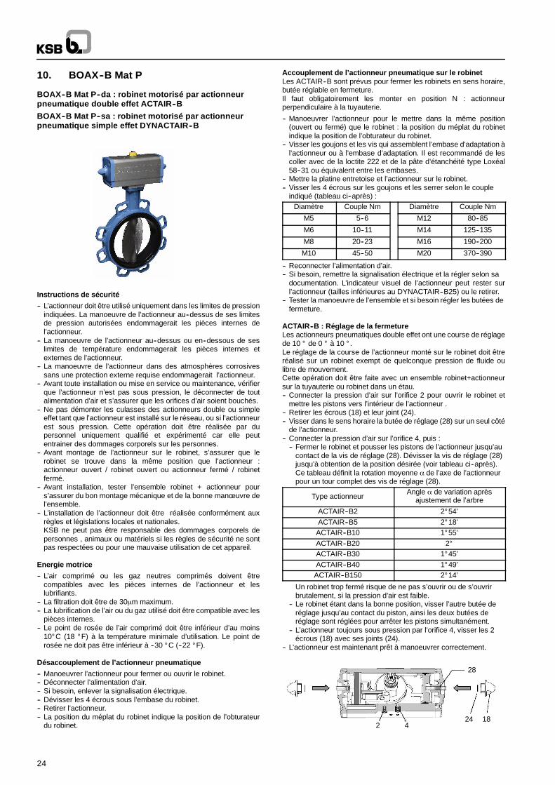
24
10. BOAX--B Mat P
BOAX--B Mat P--da : robinet motorisé par actionneurpneumatique double effet ACTAIR--B
BOAX--B Mat P--sa : robinet motorisé par actionneurpneumatique simple effet DYNACTAIR--B
Instructions de sécurité
-- L’actionneur doit être utilisé uniquement dans les limites de pressionindiquées. La manoeuvre de l’actionneur au--dessus de ses limitesde pression autorisées endommagerait les pièces internes del’actionneur.
-- La manoeuvre de l’actionneur au--dessus ou en--dessous de seslimites de température endommagerait les pièces internes etexternes de l’actionneur.
-- La manoeuvre de l’actionneur dans des atmosphères corrosivessans une protection externe requise endommagerait l’actionneur.
-- Avant toute installation ou mise en service ou maintenance, vérifierque l’actionneur n’est pas sous pression, le déconnecter de toutalimentation d’air et s’assurer que les orifices d’air soient bouchés.
-- Ne pas démonter les culasses des actionneurs double ou simpleeffet tant que l’actionneur est installé sur le réseau, ou si l’actionneurest sous pression. Cette opération doit être réalisée par dupersonnel uniquement qualifié et expérimenté car elle peutentrainer des dommages corporels sur les personnes.
-- Avant montage de l’actionneur sur le robinet, s’assurer que lerobinet se trouve dans la même position que l’actionneur :actionneur ouvert / robinet ouvert ou actionneur fermé / robinetfermé.
-- Avant installation, tester l’ensemble robinet + actionneur pours’assurer du bon montage mécanique et de la bonne manœ uvre del’ensemble.
-- L’installation de l’actionneur doit être réalisée conformément auxrègles et législations locales et nationales.KSB ne peut pas être responsable des dommages corporels depersonnes , animaux ou matériels si les règles de sécurité ne sontpas respectées ou pour une mauvaise utilisation de cet appareil.
Energie motrice
-- L’air comprimé ou les gaz neutres comprimés doivent êtrecompatibles avec les pièces internes de l’actionneur et leslubrifiants.
-- La filtration doit être de 30µm maximum.-- La lubrification de l’air ou du gaz utilisé doit être compatible avec les
pièces internes.-- Le point de rosée de l’air comprimé doit être inférieur d’au moins
10° C (18 ° F) à la température minimale d’utilisation. Le point derosée ne doit pas être inférieur à --30 ° C (--22 ° F).
Désaccouplement de l’actionneur pneumatique
-- Manoeuvrer l’actionneur pour fermer ou ouvrir le robinet.-- Déconnecter l’alimentation d’air.-- Si besoin, enlever la signalisation électrique.-- Dévisser les 4 écrous sous l’embase du robinet.-- Retirer l’actionneur.-- La position du méplat du robinet indique la position de l’obturateur
du robinet.
Accouplement de l’actionneur pneumatique sur le robinetLes ACTAIR--B sont prévus pour fermer les robinets en sens horaire,butée réglable en fermeture.Il faut obligatoirement les monter en position N : actionneurperpendiculaire à la tuyauterie.
-- Manoeuvrer l’actionneur pour le mettre dans la même position(ouvert ou fermé) que le robinet : la position du méplat du robinetindique la position de l’obturateur du robinet.
-- Visser les goujons et les vis qui assemblent l’embase d’adaptation àl’actionneur ou à l’embase d’adaptation. Il est recommandé de lescoller avec de la loctite 222 et de la pâte d’étanchéité type Loxéal58--31 ou équivalent entre les embases.
-- Mettre la platine entretoise et l’actionneur sur le robinet.-- Visser les 4 écrous sur les goujons et les serrer selon le couple
indiqué (tableau ci--après) :Diamètre Couple Nm Diamètre Couple Nm
M5 5--6 M12 80--85
M6 10--11 M14 125--135
M8 20--23 M16 190--200
M10 45--50 M20 370--390
-- Reconnecter l’alimentation d’air.-- Si besoin, remettre la signalisation électrique et la régler selon sa
documentation. L’indicateur visuel de l’actionneur peut rester surl’actionneur (tailles inférieures au DYNACTAIR--B25) ou le retirer.
-- Tester la manoeuvre de l’ensemble et si besoin régler les butées defermeture.
ACTAIR--B : Réglage de la fermetureLes actionneurs pneumatiques double effet ont une course de réglagede 10 ° de 0 ° à 10 ° .Le réglage de la course de l’actionneur monté sur le robinet doit êtreréalisé sur un robinet exempt de quelconque pression de fluide oulibre de mouvement.Cette opération doit être faite avec un ensemble robinet+actionneursur la tuyauterie ou robinet dans un étau.-- Connecter la pression d’air sur l’orifice 2 pour ouvrir le robinet et
mettre les pistons vers l’intérieur de l’actionneur .-- Retirer les écrous (18) et leur joint (24).-- Visser dans le sens horaire la butée de réglage (28) sur un seul côté
de l’actionneur.-- Connecter la pression d’air sur l’orifice 4, puis :
-- Fermer le robinet et pousser les pistons de l’actionneur jusqu’aucontact de la vis de réglage (28). Dévisser la vis de réglage (28)jusqu’à obtention de la position désirée (voir tableau ci--après).Ce tableau définit la rotation moyenne α de l’axe de l’actionneurpour un tour complet des vis de réglage (28).
Type actionneurAngle α de variation après
ajustement de l’arbre
ACTAIR--B2 2° 54’ACTAIR--B5 2° 18’ACTAIR--B10 1° 55’ACTAIR--B20 2°ACTAIR--B30 1° 45’ACTAIR--B40 1° 49’ACTAIR--B150 2° 14’
Un robinet trop fermé risque de ne pas s’ouvrir ou de s’ouvrirbrutalement, si la pression d’air est faible.
-- Le robinet étant dans la bonne position, visser l’autre butée deréglage jusqu’au contact du piston, ainsi les deux butées deréglage sont réglées pour arrêter les pistons simultanément.
-- L’actionneur toujours sous pression par l’orifice 4, visser les 2écrous (18) avec ses joints (24).
-- L’actionneur est maintenant prêt à manoeuvrer correctement.
2 4
28
24 18
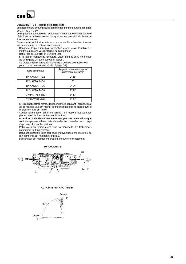
25
DYNACTAIR--B : Réglage de la fermetureLes actionneurs pneumatiques simple effet ont une course de réglagede 10 ° de 0 ° à 10 ° .Le réglage de la course de l’actionneur monté sur le robinet doit êtreréalisé sur un robinet exempt de quelconque pression de fluide oulibre de mouvement.Cette opération doit être faite avec un ensemble robinet+actionneursur la tuyauterie ou robinet dans un étau.-- Connecter la pression d’air sur l’orifice 4 pour ouvrir le robinet et
mettre les pistons vers l’intérieur de l’actionneur.-- Retirer les écrous (18) et leur joint (24).-- Si le robinet manque de fermeture, visser dans le sens horaire les
vis de réglage 28 (voir tableau ci--après).Ce tableau définit la rotation moyenne α de l’axe de l’actionneurpour un tour complet des vis de réglage (28).
Type actionneurAngle α de variation après
ajustement de l’arbre
DYNACTAIR--B2 2° 26’
DYNACTAIR--B4 2°
DYNACTAIR--B6 2° 14’
DYNACTAIR--B8 1° 54’
DYNACTAIR--B12 1° 40’
DYNACTAIR--B16 1° 54’
-- Si le robinet est trop fermé, dévisser dans le sens anti--horaire, les 2vis de réglage (28). Un robinet trop fermé risque de ne pas s’ouvrir sila pression d’air est faible.
-- Couper l’alimentation en air comprimé : les ressorts poussent lespistons vers l’intérieur et ferment le robinet.Attention : La butée sur fermeture n’est pas une butée mécaniquecontre les pistons et l’axe mais elle arrête la course des ressorts quin’appuient plus sur les pistons.L’obturateur du robinet étant dans sa manchette, les frottementsempêchent tout mouvement.Dans cette position, l’axe peut tourner davantage en fermeture si del’air comprimé est mis dans l’orifice 2.
-- L’actionneur est maintenant prêt à manoeuvrer correctement.
424 18
28
22
DYNACTAIR--B
--1°9 °
92 °
91 °
Ouvert
Fermé
ACTAIR--B / DYNACTAIR--B
2
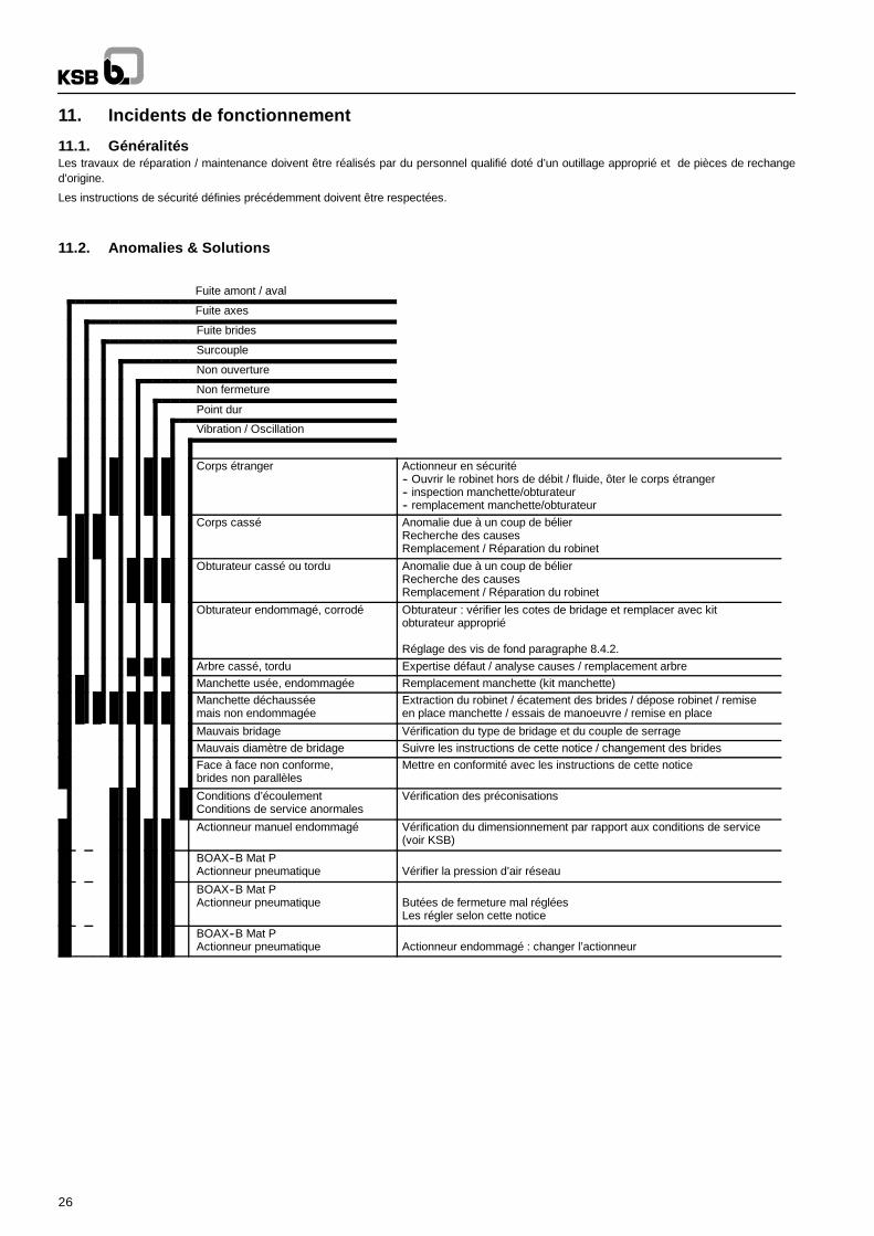
26
11. Incidents de fonctionnement
11.1. GénéralitésLes travaux de réparation / maintenance doivent être réalisés par du personnel qualifié doté d’un outillage approprié et de pièces de rechanged’origine.
Les instructions de sécurité définies précédemment doivent être respectées.
11.2. Anomalies & Solutions
Fuite amont / aval
Fuite axes
Fuite brides
Surcouple
Non ouverture
Non fermeture
Point dur
Vibration / Oscillation
Corps étranger Actionneur en sécurité-- Ouvrir le robinet hors de débit / fluide, ôter le corps étranger-- inspection manchette/obturateur-- remplacement manchette/obturateur
Corps cassé Anomalie due à un coup de bélierRecherche des causesRemplacement / Réparation du robinet
Obturateur cassé ou tordu Anomalie due à un coup de bélierRecherche des causesRemplacement / Réparation du robinet
Obturateur endommagé, corrodé Obturateur : vérifier les cotes de bridage et remplacer avec kitobturateur approprié
Réglage des vis de fond paragraphe 8.4.2.Arbre cassé, tordu Expertise défaut / analyse causes / remplacement arbreManchette usée, endommagée Remplacement manchette (kit manchette)Manchette déchausséemais non endommagée
Extraction du robinet / écatement des brides / dépose robinet / remiseen place manchette / essais de manoeuvre / remise en place
Mauvais bridage Vérification du type de bridage et du couple de serrageMauvais diamètre de bridage Suivre les instructions de cette notice / changement des bridesFace à face non conforme,brides non parallèles
Mettre en conformité avec les instructions de cette notice
Conditions d’écoulementConditions de service anormales
Vérification des préconisations
Actionneur manuel endommagé Vérification du dimensionnement par rapport aux conditions de service(voir KSB)
BOAX--B Mat PActionneur pneumatique Vérifier la pression d’air réseau
BOAX--B Mat PActionneur pneumatique Butées de fermeture mal réglées
Les régler selon cette notice
BOAX--B Mat PActionneur pneumatique Actionneur endommagé : changer l’actionneur
27
3. GeneralThese operating instructions apply to KSB rubber lined butterflyvalves (see section 5).
Design, manufacturing and testing of the KSB valves are subject to aQuality Assurance System according to EN ISO 9001 and to theEuropean Pressure Equipment Directive 97/23/EC (PED).
For a specific product configuration as an actuated valve, theaggregate can be considered as a partly completed machineaccording to the machinery directive 2006/42/EC and comply with therequirements of the directive.
Correct installation is mandatory to ensure trouble free operation ofthe valves.
The manufacturer cannot be made liable for these valves if operatinginstructions are not being observed.
ATTENTION The valves must not be operated outside thepermissible operating range. The limits are indicated on the nameplate or currently applicable type leaflet. The pressure-temperatureratings, in particular, must not be exceeded. Operation of the valvesoutside the above-mentioned conditions may result in overloadswhich may damage the valves.
The type leaflets can be found at www.ksb.com – product catalogue.
Nonobservance of this warning may lead to personal injury orproperty damage, e.g.:-- Injury caused by escaping fluids (cold/hot, flammable or under
pressure)-- Incorrect operation or destruction of the valve.
The descriptions and instructions in this manual refer to the standardversions but also apply to the related variants.
These operating instructions do not take into consideration:
-- incidents which may occur during installation and operation.-- the local safety regulations. lt is the user’s responsibility to ensure
that these are also observed by the installation staff involved.
For actuated valves, the specified connection parameters and theinstallation instructions -- including the operating manual for theactuator -- must be observed.
ATTENTION Handling a valve requires skilled and experiencedpersonnel.
The personnel in charge of operation and installation of this valve mustbe aware of the interaction between the valve and the plant.
Operator’s errors concerning the valve may have seriousconsequences for the entire plant, e.g.:-- fluid may escape-- downtime of the plant/machine-- adverse effect/reduction/increase of the efficiency/function of a
plant/machine.For further questions or in case of damage to the valve, please contactyour KSB Sales Office.
For further questions and supplementary orders, please always statethe indications of the marking plate.
The specifications (operating data) of the valves are listed in thetechnical documentation and type leaflet of the related valve (see alsosection 5).
When returning valves to the manufacturer, please refer to section 4.
4. SafetyThis manual contains basic instructions to be complied with duringoperation. lt is therefore vital for the fitter and the operator/user to readthis manual before installing/commissioning the valve. Also, thismanual must always be available at the site where the valve isinstalled.
lt is not enough to observe the general instructions listed in the section”safety”, the specific safety instructions listed in the other sectionsshould also be observed.
4.1. Safety Symbols in these OperatingInstructions
Safety instructions put forth in this instructions manual, thenonobservance of which would involve the risk of personal injury, theyare specially marked with the general hazard symbol:
in accordance with ISO 3864--B.3.1.or with the electric voltage warning sign:
In accordance with ISO 3864--B.3.6.
Safety instructions the nonobservance of which would involve hazardto the valve and jeopardize its operation have been marked with theword
ATTENTION
lnstructions directly attached to the valve, (e.g. nominal pressure)must be complied with and maintained in a legible condition.
4.2. Qualification of personnel and trainingThe personnel for operation, maintenance, Inspection and installationmust be adequately qualified for the work involved. The personnelresponsibility, competence and supervision must be clearly defined bythe user. lf the personnel in question is not already in possession of therequired know-how, appropriate training and instructions must beprovided. lf deemed necessary, the manufacturer/supplier will providesuch training and instructions at the user’s request. In addition, theuser is responsible for ensuring that the contents of these operatinginstructions are fully understood by the personnel involved.
4.3. Danger or nonobservance of the safetyinstructions
Nonobservance of the safety instructions may lead to personal injuryand danger for both the environment and the valve itself.Nonobservance of these safety instructions will also forfeit the user’swarranty.
Such noncompliance could result in for example :
-- failure of essential functions of the valve/plant-- hazard to people by electrical, mechanical or chemical effects-- hazard to the environment due to leakage of hazardous
substances.
4.4. Safety ConsciousnessThe safety instructions contained in this manual, the applicablenational accident prevention regulations and any of the user’s ownapplicable internal work, operation or safety instructions must be fullycomplied with.
4.5. Safety Instructions for the User/OperatorAny hot or cold parts of the valve (e.g. body or handle or actuator) thatcould cause a hazard must be protected by the user against accidentalcontact.
Leakage of hazardous substance (e.g. flammable, hot) must bedrained so as to avoid all danger to people or the environment. Allrelevant laws must be observed.
Electrical hazards must be effectively prevented. (For details,please refer to the IEC 364 or equivalent national standard and/orlocal utility energy supply regulations).
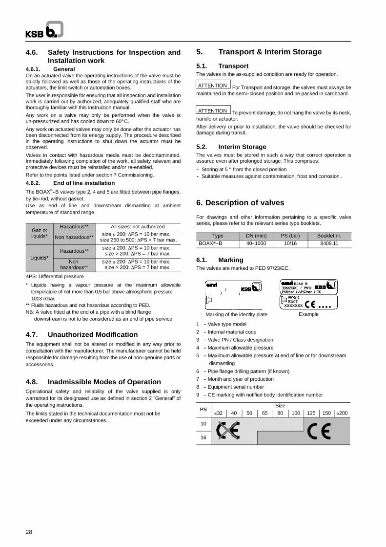
28
4.6. Safety lnstructions for Inspection andInstallation work
4.6.1. GeneralOn an actuated valve the operating instructions of the valve must bestrictly followed as well as those of the operating instructions of theactuators, the limit switch or automation boxes.
The user is responsible for ensuring that all inspection and installationwork is carried out by authorized, adequately qualified staff who arethoroughly familiar with this instruction manual.
Any work on a valve may only be performed when the valve isun-pressurized and has cooled down to 60° C.
Any work on actuated valves may only be done after the actuator hasbeen disconnected from its energy supply. The procedure describedin the operating instructions to shut down the actuator must beobserved.
Valves in contact with hazardous media must be decontaminated.Immediately following completion of the work, all safety relevant andprotective devices must be reinstalled and/or re-enabled.
Refer to the points listed under section 7 Commissioning.
4.6.2. End of line installation
The BOAX--B valves type 2, 4 and 5 are fitted between pipe flanges,by tie--rod, without gasket.Use as end of line and downstream dismantling at ambienttemperature of standard range.
Gaz orHazardous** All sizes: not authorized
Gaz orliquids* Non hazardous**
size ≤ 200: ∆PS = 10 bar max.size 250 to 500: ∆PS = 7 bar max.
Liquids*Hazardous**
size ≤ 200: ∆PS = 10 bar max.size > 200: ∆PS = 7 bar max.
Liquids*Non
hazardous**size ≤ 200: ∆PS = 10 bar max.size > 200: ∆PS = 7 bar max.
∆PS: Differential pressure
* Liquids having a vapour pressure at the maximum allowabletemperature of not more than 0,5 bar above atmospheric pressure1013 mbar.
** Fluids hazardous and not hazardous according to PED.NB: A valve fitted at the end of a pipe with a blind flange
downstream is not to be considered as an end of pipe service.
4.7. Unauthorized ModificationThe equipment shall not be altered or modified in any way prior toconsultation with the manufacturer. The manufacturer cannot be heldresponsible for damage resulting from the use of non--genuine parts oraccessories.
4.8. Inadmissible Modes of OperationOperational safety and reliability of the valve supplied is onlywarranted for its designated use as defined in section 2 ”General”ofthe operating instructions.
The limits stated in the technical documentation must not beexceeded under any circumstances.
5. Transport & Interim Storage
5.1. TransportThe valves in the as-supplied condition are ready for operation.
ATTENTION For Transport and storage, the valves must always bemaintained in the semi--closed position and be packed in cardboard.
ATTENTION To prevent damage, do not hang the valve by its neck,handle or actuator.
After delivery or prior to installation, the valve should be checked fordamage during transit.
5.2. Interim StorageThe valves must be stored in such a way that correct operation isassured even after prolonged storage. This comprises:
-- Storing at 5 ° from the closed position-- Suitable measures against contamination, frost and corrosion .
6. Description of valves
For drawings and other information pertaining to a specific valveseries, please refer to the relevant series type booklets.
Type DN (mm) PS (bar) Booklet nr.BOAX--B 40--1000 10/16 8409.11
6.1. MarkingThe valves are marked to PED 97/23/EC.
12 3
4 56
78 9
Marking of the identity plate
01/07XXXXXXX
Example
1 -- Valve type model
2 -- Internal material code
3 -- Valve PN / Class designation
4 -- Maximum allowable pressure
5 -- Maximum allowable pressure at end of line or for downstream
dismantling
6 -- Pipe flange drilling pattern (if known)
7 -- Month and year of production
8 -- Equipment serial number
9 -- CE marking with notified body identification number
PSSize
PS≤32 40 50 65 80 100 125 150 ≥200
10
16
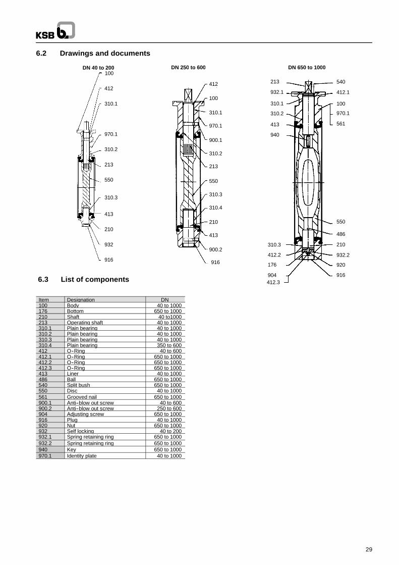
29
6.2 Drawings and documents
100
412
310.1
970.1
310.2
213
550
310.3
413
210
916
100
412
310.1
900.1
970.1
310.2
213
550
310.3
413
210
916
310.4
900.2
DN 250 to 600 DN 650 to 1000
932.1
100
940
412.2
213
550
210
561
540
310.1
413
412.1
970.1
176
310.2
920
904
310.3
412.3
932.2
486
916
932
DN 40 to 200
6.3 List of components
Item Designation DN100 Body 40 to 1000176 Bottom 650 to 1000210 Shaft 40 to1000213 Operating shaft 40 to 1000310.1 Plain bearing 40 to 1000310.2 Plain bearing 40 to 1000310.3 Plain bearing 40 to 1000310.4 Plain bearing 350 to 600412 O--Ring 40 to 600412.1 O--Ring 650 to 1000412.2 O--Ring 650 to 1000412.3 O--Ring 650 to 1000413 Liner 40 to 1000486 Ball 650 to 1000540 Split bush 650 to 1000550 Disc 40 to 1000561 Grooved nail 650 to 1000900.1 Anti--blow out screw 40 to 600900.2 Anti--blow out screw 250 to 600904 Adjusting screw 650 to 1000916 Plug 40 to 1000920 Nut 650 to 1000932 Self locking 40 to 200932.1 Spring retaining ring 650 to 1000932.2 Spring retaining ring 650 to 1000940 Key 650 to 1000970.1 Identity plate 40 to 1000
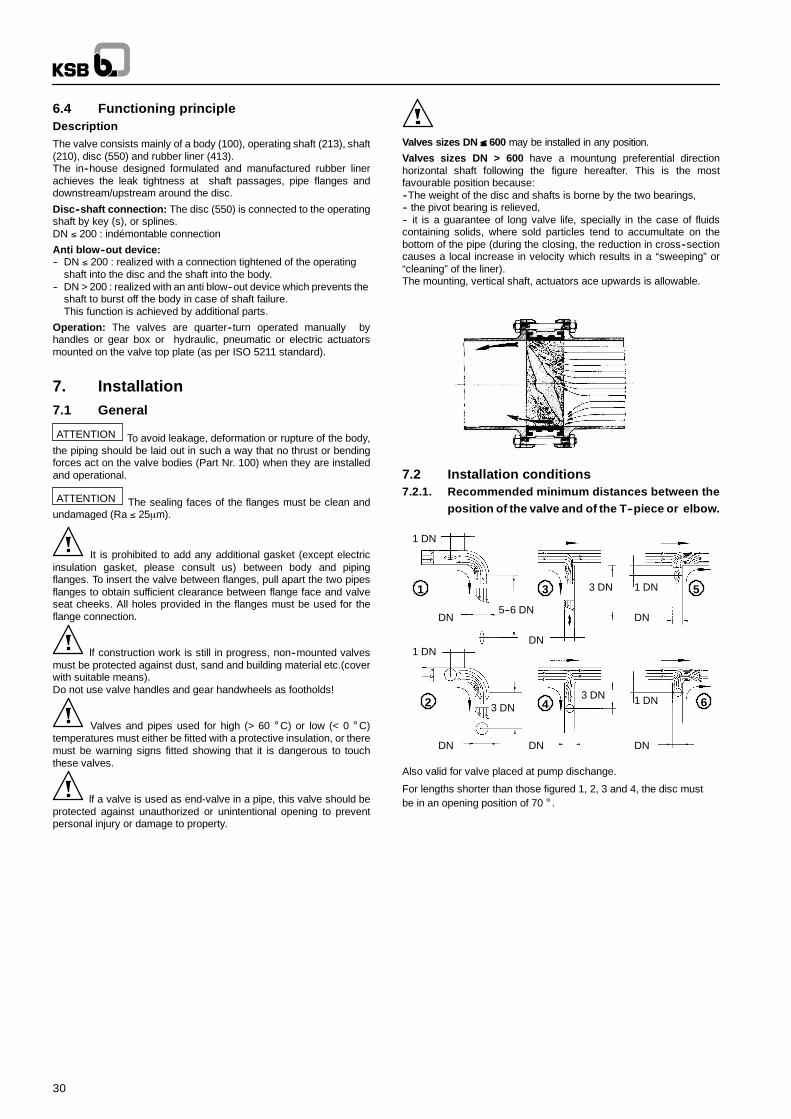
30
6.4 Functioning principleDescriptionThe valve consists mainly of a body (100), operating shaft (213), shaft(210), disc (550) and rubber liner (413).The in--house designed formulated and manufactured rubber linerachieves the leak tightness at shaft passages, pipe flanges anddownstream/upstream around the disc.
Disc--shaft connection: The disc (550) is connected to the operatingshaft by key (s), or splines.DN ≤ 200 : indémontable connection
Anti blow--out device:-- DN ≤ 200 : realized with a connection tightened of the operating
shaft into the disc and the shaft into the body.-- DN > 200 : realized with an anti blow--out device which prevents the
shaft to burst off the body in case of shaft failure.This function is achieved by additional parts.
Operation: The valves are quarter--turn operated manually byhandles or gear box or hydraulic, pneumatic or electric actuatorsmounted on the valve top plate (as per ISO 5211 standard).
7. Installation7.1 General
ATTENTION To avoid leakage, deformation or rupture of the body,the piping should be laid out in such a way that no thrust or bendingforces act on the valve bodies (Part Nr. 100) when they are installedand operational.
ATTENTION The sealing faces of the flanges must be clean andundamaged (Ra ≤ 25µm).
It is prohibited to add any additional gasket (except electricinsulation gasket, please consult us) between body and pipingflanges. To insert the valve between flanges, pull apart the two pipesflanges to obtain sufficient clearance between flange face and valveseat cheeks. All holes provided in the flanges must be used for theflange connection.
lf construction work is still in progress, non--mounted valvesmust be protected against dust, sand and building material etc.(coverwith suitable means).Do not use valve handles and gear handwheels as footholds!
Valves and pipes used for high (> 60 ° C) or low (< 0 ° C)temperatures must either be fitted with a protective insulation, or theremust be warning signs fitted showing that it is dangerous to touchthese valves.
lf a valve is used as end-valve in a pipe, this valve should beprotected against unauthorized or unintentional opening to preventpersonal injury or damage to property.
Valves sizes DN ≤ 600 may be installed in any position.
Valves sizes DN > 600 have a mountung preferential directionhorizontal shaft following the figure hereafter. This is the mostfavourable position because:--The weight of the disc and shafts is borne by the two bearings,-- the pivot bearing is relieved,-- it is a guarantee of long valve life, specially in the case of fluidscontaining solids, where sold particles tend to accumultate on thebottom of the pipe (during the closing, the reduction in cross--sectioncauses a local increase in velocity which results in a “sweeping”or“cleaning”of the liner).The mounting, vertical shaft, actuators ace upwards is allowable.
7.2 Installation conditions7.2.1. Recommended minimum distances between the
position of the valve and of the T--piece or elbow.
DN
1 DN
DNDN
1 DN
DN
3 DN
DNDN
1 DN
1 DN
3 DN
5--6 DN
3 DN1 3 5
642
Also valid for valve placed at pump dischange.
For lengths shorter than those figured 1, 2, 3 and 4, the disc mustbe in an opening position of 70 ° .
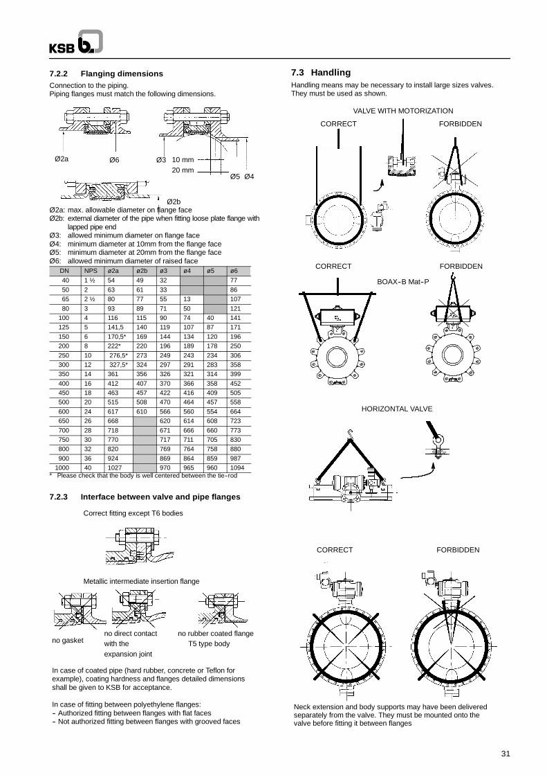
31
7.2.2 Flanging dimensionsConnection to the piping.Piping flanges must match the following dimensions.
Ø2a Ø6 Ø3
Ø5 Ø4
10 mm
Ø2b
20 mm
Ø2a: max. allowable diameter on flange faceØ2b: external diameter of the pipe when fitting loose plate flange with
lapped pipe endØ3: allowed minimum diameter on flange faceØ4: minimum diameter at 10mm from the flange faceØ5: minimum diameter at 20mm from the flange faceØ6: allowed minimum diameter of raised face
DN NPS ø2a ø2b ø3 ø4 ø5 ø640 1 ½ 54 49 32 7750 2 63 61 33 8665 2 ½ 80 77 55 13 10780 3 93 89 71 50 121
100 4 116 115 90 74 40 141125 5 141,5 140 119 107 87 171150 6 170,5* 169 144 134 120 196200 8 222* 220 196 189 178 250250 10 276,5* 273 249 243 234 306300 12 327,5* 324 297 291 283 358350 14 361 356 326 321 314 399400 16 412 407 370 366 358 452450 18 463 457 422 416 409 505500 20 515 508 470 464 457 558600 24 617 610 566 560 554 664650 26 668 620 614 608 723700 28 718 671 666 660 773750 30 770 717 711 705 830800 32 820 769 764 758 880900 36 924 869 864 859 987
1000 40 1027 970 965 960 1094* Please check that the body is well centered between the tie--rod
7.2.3 Interface between valve and pipe flanges
Correct fitting except T6 bodies
Metallic intermediate insertion flange
no rubber coated flangeT5 type body
no direct contactwith theexpansion joint
no gasket
In case of coated pipe (hard rubber, concrete or Teflon forexample), coating hardness and flanges detailed dimensionsshall be given to KSB for acceptance.
In case of fitting between polyethylene flanges:-- Authorized fitting between flanges with flat faces-- Not authorized fitting between flanges with grooved faces
7.3 HandlingHandling means may be necessary to install large sizes valves.They must be used as shown.
VALVE WITH MOTORIZATION
CORRECT FORBIDDEN
HORIZONTAL VALVE
CORRECT FORBIDDEN
BOAX--B Mat--P
CORRECT FORBIDDEN
Neck extension and body supports may have been deliveredseparately from the valve. They must be mounted onto thevalve before fitting it between flanges
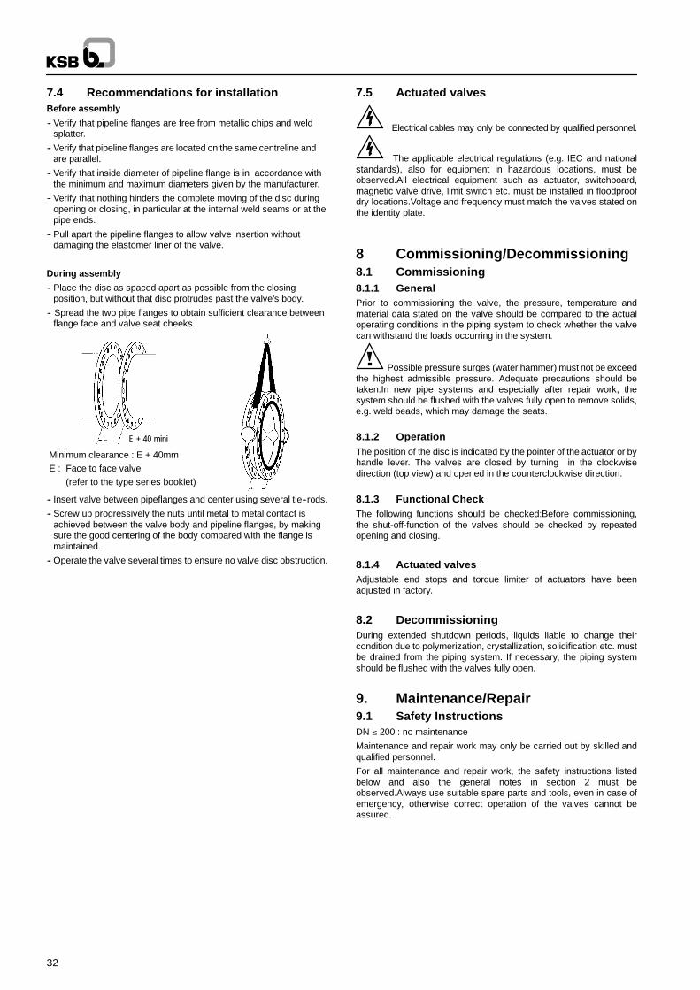
32
7.4 Recommendations for installationBefore assembly
-- Verify that pipeline flanges are free from metallic chips and weldsplatter.
-- Verify that pipeline flanges are located on the same centreline andare parallel.
-- Verify that inside diameter of pipeline flange is in accordance withthe minimum and maximum diameters given by the manufacturer.
-- Verify that nothing hinders the complete moving of the disc duringopening or closing, in particular at the internal weld seams or at thepipe ends.
-- Pull apart the pipeline flanges to allow valve insertion withoutdamaging the elastomer liner of the valve.
During assembly
-- Place the disc as spaced apart as possible from the closingposition, but without that disc protrudes past the valve’s body.
-- Spread the two pipe flanges to obtain sufficient clearance betweenflange face and valve seat cheeks.
E + 40 mini
E
Minimum clearance : E + 40mmE : Face to face valve
(refer to the type series booklet)
-- Insert valve between pipeflanges and center using several tie--rods.
-- Screw up progressively the nuts until metal to metal contact isachieved between the valve body and pipeline flanges, by makingsure the good centering of the body compared with the flange ismaintained.
-- Operate the valve several times to ensure no valve disc obstruction.
7.5 Actuated valves
Electrical cables may only be connected by qualified personnel.
The applicable electrical regulations (e.g. IEC and nationalstandards), also for equipment in hazardous locations, must beobserved.All electrical equipment such as actuator, switchboard,magnetic valve drive, limit switch etc. must be installed in floodproofdry locations.Voltage and frequency must match the valves stated onthe identity plate.
8 Commissioning/Decommissioning8.1 Commissioning8.1.1 GeneralPrior to commissioning the valve, the pressure, temperature andmaterial data stated on the valve should be compared to the actualoperating conditions in the piping system to check whether the valvecan withstand the loads occurring in the system.
Possible pressure surges (water hammer) must not be exceedthe highest admissible pressure. Adequate precautions should betaken.In new pipe systems and especially after repair work, thesystem should be flushed with the valves fully open to remove solids,e.g. weld beads, which may damage the seats.
8.1.2 OperationThe position of the disc is indicated by the pointer of the actuator or byhandle lever. The valves are closed by turning in the clockwisedirection (top view) and opened in the counterclockwise direction.
8.1.3 Functional CheckThe following functions should be checked:Before commissioning,the shut-off-function of the valves should be checked by repeatedopening and closing.
8.1.4 Actuated valvesAdjustable end stops and torque limiter of actuators have beenadjusted in factory.
8.2 DecommissioningDuring extended shutdown periods, liquids liable to change theircondition due to polymerization, crystallization, solidification etc. mustbe drained from the piping system. If necessary, the piping systemshould be flushed with the valves fully open.
9. Maintenance/Repair9.1 Safety InstructionsDN ≤ 200 : no maintenance
Maintenance and repair work may only be carried out by skilled andqualified personnel.
For all maintenance and repair work, the safety instructions listedbelow and also the general notes in section 2 must beobserved.Always use suitable spare parts and tools, even in case ofemergency, otherwise correct operation of the valves cannot beassured.
33
9.2 Valve removal from piping and actuatordisconnecting
Identify the valve by identity plate.
Please check what is the relevant spare kit.Place the disc at 10 ° opening.
The entire valve must be unpressurized and must have cooleddown sufficiently so that the temperature of the medium is lower than60 ° C, to prevent scalding.
Opening pressurized valves will cause danger to life andlimb!lf toxic or highly flammable substances or liquids whose residuesmay cause corrosion by interaction with the air humidity were handledby the valve, then the valve should be drained and flushed or vented.lfnecessary, wear safety clothing and a face guard/mask.Depending onthe installation position, any liquid remaining in the valve may have tobe removed.
Prior to possible transport, the valves must be flushed and drainedcarefully.lf you have any questions please contact your KSB SalesOffice.
lf actuators powered by an external source of energy (electric,pneumatic, hydraulic) need to be removed from the valves ordismantled, the energy supply must be shut down prior to starting anyrepair work.
Remove the valve from the piping with its actuator. Do notdamage the liner during removal the valve from the pipe. Therefore,pull apart the pipe flanges to allow sufficient clearance.
Identify the mounting position of the actuator
Disconnect the actuator and take care of all bolting parts.
9.3 Spares, list of tools, Consummables9.3.1 SparesDN ≤ 200 : no kit
Use the relevant spare parts included in the liner kit or disc kit or shaftkit. Please refer to leaflets.All constitutive parts of kits must be replaced.
During the mounting /dismantling of the valve, the order ofoperations given in § 8.4.1. must be respected to prevent injuries andmaterial damages.
During the tests, while closing and opening valves, care must be takenthat no operator interferes with the disc travel.
9.3.2 List of tools for mounting/dismantlingPneumatic screwing machine, open ended spanner, ring spanner, boxspanner, screwdrivers, hammer, pneumatic polisher, wedges, crowbar and silicon grease if authorized.
9.3.3 ConsummablesUse only the grease SF enclosed in the kit (amlub). The use ofmechanical grease is strictly prohibited.
9.4 Valve disassembly and re--assembly9.4.1 Valve disassemblyRemove the plug (916) or bottom (176) , the spring retaining ring (932)if any.
Remove the anti blow--out screws (900.*) and gasket holder (559) ifany.
Extract the operating shaft (213) and lower shaft (210)
Remove the disc (550) and dismantle the liner (413)
Take care to prevent disc edge, liner and paint from anydamage.
Change O--rings 412.* using silicon grease. Put grease onto the linerat shaft passages.
9.4.2 Valve re--assemblyPut in place the liner (413) into the body (100) so that shaft passagesare correctly aligned with the bores of the body.
Insert the disc (550) in open position and check correct alignment ofshaft passages.
Mount the shaft (210) with the ball (486) / keys (940.*) or springretaining ring (932), the washer (554) and screw (901.*) if any.
DN 250 to 600:
Check that the groove of the shaft and operating shaft are in front of theanti blow--out screws (900.1) and (900.2) as shown on the drawinghereunder:
CORRECT WRONG
Mount the operating shaft (213) with keys (940.*) if any. Check thecorrect indexation with the disc edge (550)
Adjust the anti blow--out screws (900.*)
Mount the plug (916) or bottom (176) and gasket holder (559) if any.
Valves with a bottom(176) must be put in a horizontal position to adjustscrew (904) which is to be locked with nut (920).
9.5 Test and re--installationReassemble the actuator (check the N or M position)
Open the valve at 10 ° opening.
Pull apart the pipeline flanges to allow valve insertion withoutdamaging the elastomer liner of the valve.
Connect the power supply if necessary.
Check that the valve can be fully operated by the actuator.
Connect the valve to the pipe and follow assembling instructions.
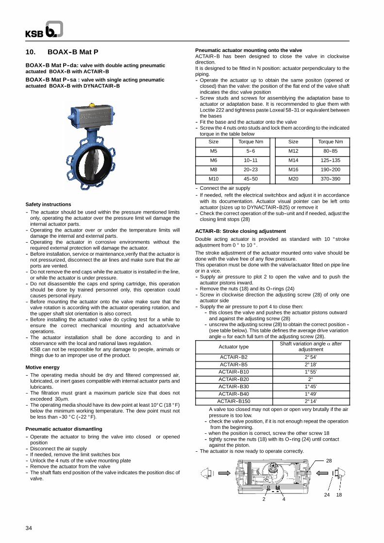
34
10. BOAX--B Mat P
BOAX--B Mat P--da: valve with double acting pneumaticactuated BOAX--B with ACTAIR--B
BOAX--B Mat P--sa : valve with single acting pneumaticactuated BOAX--B with DYNACTAIR--B
Safety instructions
-- The actuator should be used within the pressure mentioned limitsonly, operating the actuator over the pressure limit wil damage theinternal actuator parts.
-- Operating the actuator over or under the temperature limits willdamage the internal and external parts.
-- Operating the actuator in corrosive environments without therequired external protection will damage the actuator.
-- Before installation, service or maintenance,verify that the actuator isnot pressurized, disconnect the air lines and make sure that the airports are vented.
-- Do not remove the end caps while the actuator is installed in the line,or while the actuator is under pressure.
-- Do not disassemble the caps end spring cartridge, this operationshould be done by trained personnel only, this operation couldcauses personal injury.
-- Before mounting the actuator onto the valve make sure that thevalve rotation is according with the actuator operating rotation, andthe upper shaft slot orientation is also correct.
-- Before installing the actuated valve do cycling test for a while toensure the correct mechanical mounting and actuator/valveoperations.
-- The actuator installation shall be done according to and inobservance with the local and national laws regulation.KSB can not be responsible for any damage to people, animals orthings due to an improper use of the product.
Motive energy
-- The operating media should be dry and filtered compressed air,lubricated, or inert gases compatible with internal actuator parts andlubricants.
-- The filtration must grant a maximum particle size that does notexcedeed 30µm.
-- The operating media should have its dew point at least 10° C (18 ° F)below the minimum working temperature. The dew point must notbe less than --30 ° C (--22 ° F).
Pneumatic actuator dismantling
-- Operate the actuator to bring the valve into closed or openedposition
-- Disconnect the air supply-- If needed, remove the limit switches box-- Unlock the 4 nuts of the valve mounting plate-- Remove the actuator from the valve-- The shaft flats end position of the valve indicates the position disc of
valve.
Pneumatic actuator mounting onto the valveACTAIR--B has been designed to close the valve in clockwisedirection.It is designed to be fitted in N position: actuator perpendiculary to thepiping.-- Operate the actuator up to obtain the same positon (opened or
closed) than the valve: the position of the flat end of the valve shaftindicates the disc valve position
-- Screw studs and screws for assemblying the adaptation base toactuator or adaptation base. It is recommended to glue them withLoctite 222 and tightness paste Loxeal 58--31 or equivalent betweenthe bases
-- Fit the base and the actuator onto the valve-- Screw the 4 nuts onto studs and lock them according to the indicated
torque in the table below
Size Torque Nm Size Torque Nm
M5 5--6 M12 80--85
M6 10--11 M14 125--135
M8 20--23 M16 190--200
M10 45--50 M20 370--390
-- Connect the air supply-- If needed, refit the electrical switchbox and adjust it in accordance
with its documentation. Actuator visual pointer can be left ontoactuator (sizes up to DYNACTAIR--B25) or remove it
-- Check the correct operation of the sub--unit and if needed, adjust theclosing limit stops (28)
ACTAIR--B: Stroke closing adjustment
Double acting actuator is provided as standard with 10 ° strokeadjustment from 0 ° to 10 ° .
The stroke adjustment of the actuator mounted onto valve should bedone with the valve free of any flow pressure.This operation must be done with the valve/actuator fitted on pipe lineor in a vice.-- Supply air pressure to plot 2 to open the valve and to push the
actuator pistons inward.-- Remove the nuts (18) and its O--rings (24)-- Screw in clockwise direction the adjusting screw (28) of only one
actuator side-- Supply the air pressure to port 4 to close then:
-- this closes the valve and pushes the actuator pistons outwardand against the adjusting screw (28)
-- unscrew the adjusting screw (28) to obtain the correct position --(see table below). This table defines the average drive variationangle α for each full turn of the adjusting screw (28).
Actuator typeShaft variation angle α after
adjustment
ACTAIR--B2 2° 54’ACTAIR--B5 2° 18’ACTAIR--B10 1° 55’ACTAIR--B20 2°ACTAIR--B30 1° 45’ACTAIR--B40 1° 49’ACTAIR--B150 2° 14’
A valve too closed may not open or open very brutally if the airpressure is too low.
-- check the valve position, if it is not enough repeat the operationfrom the beginning.
-- when the position is correct, screw the other screw 18-- tightly screw the nuts (18) with its O--ring (24) until contact
against the piston.-- The actuator is now ready to operate correctly.
2 4
28
24 18
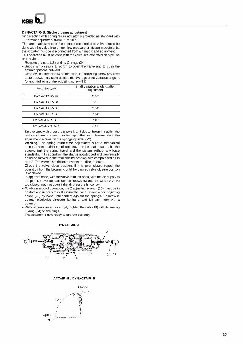
35
DYNACTAIR--B: Stroke closing adjustmentSingle acting with spring return actuator is provided as standard with10 ° stroke adjustment from 0 ° to 10 ° .The stroke adjustment of the actuator mounted onto valve should bedone with the valve free of any flow pressure or friction impediments,the actuator must be disconnected from air supply and equipment.This operation must be done with the valve/actuator fitted on pipe lineor in a vice.-- Remove the nuts (18) and its O--rings (24)-- Supply air pressure to port 4 to open the valve and to push the
actuator pistons outward.-- Unscrew, counter clockwise direction, the adjusting screw (28) (see
table below). This table defines the average drive variation angle αfor each full turn of the adjusting screw (28)
Actuator typeShaft variation angle α after
adjustment
DYNACTAIR--B2 2° 26’
DYNACTAIR--B4 2°
DYNACTAIR--B6 2° 14’
DYNACTAIR--B8 1° 54’
DYNACTAIR--B12 1° 40’
DYNACTAIR--B16 1° 54’
-- Stop to supply air pressure to port 4, and due to the spring action thepistons moves to inward position up to the limits determinate to theadjustment screws on the springs cylinder (22).Warning: The spring return close adjustment is not a mechanicalstop that acts against the pistons travel or the shaft rotation, but thescrews limit the spring travel and the pistons without any forcestandstills. In this condition the shaft is not stopped and theoreticallycould be moved to the total closing position with compressed air inport 2. The valve disc friction prevents the disc to rotate.
-- Check the valve close position, if it is over closed repeat theoperation from the beginning until the desired valve closure positionis achieved.
-- In opposite case, with the valve to much open, with the air supply tothe port 4, move both adjustment screws inward, clockwise. A valvetoo closed may not open if the air pressure is too low.
-- To obtain a good operation, the 2 adjusting screws (28) must be incontact and under stress. If it is not the case, unscrew one adjustingscrew (28) by hand until contact against the springs. Unscrew it,counter clockwise direction, by hand, and 1/8 turn more with aspanner.
-- Without pressurised air supply, tighten the nuts (18) with its sealingO--ring (24) on the plugs.
-- The actuator is now ready to operate correctly
424 18
28
22
DYNACTAIR--B
--1°9 °
92 °
91 °
Open
Closed
ACTAIR--B / DYNACTAIR--B
2
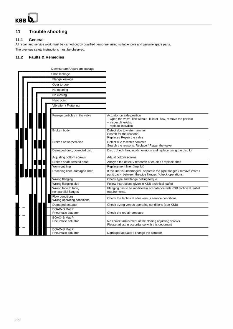
36
11 Trouble shooting
11.1 GeneralAll repair and service work must be carried out by qualified personnel using suitable tools and genuine spare parts.
The previous safety instructions must be observed.
11.2 Faults & Remedies
Downstream/Upstream leakage
Shaft leakage
Flange leakage
Over torque
No opening
No closing
Hard point
Vibration / Fluttering
Foreign particles in the valve Actuator on safe position-- Open the valve, line without fluid or flow, remove the particle-- inspect liner/disc-- replace liner/disc
Broken body Defect due to water hammerSearch for the reasons.Replace / Repair the valve
Broken or warped disc Defect due to water hammerSearch the reasons. Replace / Repair the valve
Damaged disc, corroded disc
Adjusting bottom screws
Disc : check flanging dimensions and replace using the disc kit
Adjust bottom screws
Broken shaft, twisted shaft Analyse the defect / research of causes / replace shaftWorn out liner Replacement liner (liner kit)Receding liner, damaged liner If the liner is undamaged : separate the pipe flanges / remove valve /
put it back between the pipe flanges / check operations.
Wrong flanging Check type and flange bolting torqueWrong flanging size Follow instructions given in KSB technical leafletWrong face to face,non parallel flanges
Flanging has to be modified in accordance with KSB technical leafletrequirements.
Flow conditionsWrong operating conditions Check the technical offer versus service conditions
Damaged actuator Check sizing versus operating conditions (see KSB)BOAX--B Mat PPneumatic actuator Check the red air pressure
BOAX--B Mat PPneumatic actuator No correct adjustment of the closing adjusting screws
Please adjust in accordance with this document
BOAX--B Mat PPneumatic actuator Damaged actuator : change the actuator

37
Notes

38
Notes

39
Notes

KSB S.A.S4, allée des Barbanniers • 92635 Gennevilliers Cedex (France)Tel. : +33 1 41 47 75 00 • Fax : +33 1 41 47 75 10 • www.ksb.com
BOAX--B
Leg
alin
form
atio
n/C
op
yrig
ht
--O
rigin
alop
erat
ing
man
ual-
-al
lrig
htre
serv
edC
onte
nts
prov
ided
here
inm
ustn
eith
erbe
proc
esse
dw
ithou
tKS
B’e
xpre
ssw
ritte
nco
nsen
tS
ubje
ctto
tech
nica
lmod
ifica
tion
with
outp
rior
notic
e.19
.09.
1184
11.8
01/6
--90


![Cantata No. 213 : Hercules auf dem Scheidewege …€¦ · Title: Cantata No. 213 : Hercules auf dem Scheidewege [BWV 213] Author: Bach, Johann Sebastian Subject: No commercial use](https://img.pdfslide.org/doc/110x75/5b79abc17f8b9a331e8e5687/cantata-no-213-hercules-auf-dem-scheidewege-title-cantata-no-213-hercules.jpg)