Embed Size (px)
Citation preview
CEAG 1883, 1884, 1984 LED CGLine+ 1-8h/D
Montage- und Betriebsanleitung Mounting and Operating Instructions
Zielgruppe: Elektrofachkraft
Target group: Skilled electricians
Verwendungszweck: Notbeleuchtung, nicht für privaten Gebrauch
Intended Application: Emergency Lighting, not suitable for private use
2 Manual CEAG 1883, 1884, 1984 LED CGLine+ 40071860281 August 2015 www.ceag.de
Inhaltsverzeichnis
1 Normenkonformität . . . . . . . . . . . . . . . . . . . . . . . . . . . . . . . . . . . . . . . . . . . . . . . . . . . . . .3
2 Kurzbeschreibung / Verwendungsbereich . . . . . . . . . . . . . . . . . . . . . . . . . . . . . . . . . . . . .4
3 Generelle Hinweise zu Anschluss und Inbetriebnahme der Leuchten . . . . . . . . . . . . . . . . . . . . . . . . . . . . . . . . . . . . . . . . . . . . . . .4
4 Brillant 1883, 1884 LED CGLine+ . . . . . . . . . . . . . . . . . . . . . . . . . . . . . . . . . . . . . . . . . . . . .6
4 .1 Montage . . . . . . . . . . . . . . . . . . . . . . . . . . . . . . . . . . . . . . . . . . . . . . . . . . . . . . . . . . . . .6
4 .2 Maßbilder . . . . . . . . . . . . . . . . . . . . . . . . . . . . . . . . . . . . . . . . . . . . . . . . . . . . . . . . . . . .8
5 Brillant 1984 LED CGLine+ . . . . . . . . . . . . . . . . . . . . . . . . . . . . . . . . . . . . . . . . . . . . . . . . . .9
5 .1 Montage . . . . . . . . . . . . . . . . . . . . . . . . . . . . . . . . . . . . . . . . . . . . . . . . . . . . . . . . . . . . .9
5 .2 Maßbilder . . . . . . . . . . . . . . . . . . . . . . . . . . . . . . . . . . . . . . . . . . . . . . . . . . . . . . . . . . .10
6 Installation / Inbetriebnahme . . . . . . . . . . . . . . . . . . . . . . . . . . . . . . . . . . . . . . . . . . . . . . 11
6 .1 Einstellung der Betriebsart . . . . . . . . . . . . . . . . . . . . . . . . . . . . . . . . . . . . . . . . . . . . . 11
6 .2 Dimmlevel . . . . . . . . . . . . . . . . . . . . . . . . . . . . . . . . . . . . . . . . . . . . . . . . . . . . . . . . . . .12
7 TEST und Anzeigeeinheit . . . . . . . . . . . . . . . . . . . . . . . . . . . . . . . . . . . . . . . . . . . . . . . . . .13
7 .1 Überwachungseinrichtung CGLine+ . . . . . . . . . . . . . . . . . . . . . . . . . . . . . . . . . . . . . .14
8 Technische Daten . . . . . . . . . . . . . . . . . . . . . . . . . . . . . . . . . . . . . . . . . . . . . . . . . . . . . . . .15
9 Wartung / Instandhaltung . . . . . . . . . . . . . . . . . . . . . . . . . . . . . . . . . . . . . . . . . . . . . . . . .15
10Entsorgung / Recycling . . . . . . . . . . . . . . . . . . . . . . . . . . . . . . . . . . . . . . . . . . . . . . . . . . .15
Index
1 Conformity with standards . . . . . . . . . . . . . . . . . . . . . . . . . . . . . . . . . . . . . . . . . . . . . . . .3
2 Brief description / Scope of application . . . . . . . . . . . . . . . . . . . . . . . . . . . . . . . . . . . . . . .4
3 eneral notes for connection and operation of the luminaires . . . . . . . . . . . . . . . . . . . . . . . . . . . . . . . . . . . . . . . . . . . . . . . . .4
4 Brillant 1883, 1884 LED CGLine+ . . . . . . . . . . . . . . . . . . . . . . . . . . . . . . . . . . . . . . . . . . . . .6
4 .1 Mounting . . . . . . . . . . . . . . . . . . . . . . . . . . . . . . . . . . . . . . . . . . . . . . . . . . . . . . . . . . . . .6
4 .2 Dimensional drawings . . . . . . . . . . . . . . . . . . . . . . . . . . . . . . . . . . . . . . . . . . . . . . . . . .8
5 Brillant 1984 LED CGLine+ . . . . . . . . . . . . . . . . . . . . . . . . . . . . . . . . . . . . . . . . . . . . . . . . . .9
5 .1 Mounting . . . . . . . . . . . . . . . . . . . . . . . . . . . . . . . . . . . . . . . . . . . . . . . . . . . . . . . . . . . . .9
5 .2 Dimensional drawings . . . . . . . . . . . . . . . . . . . . . . . . . . . . . . . . . . . . . . . . . . . . . . . . .10
6 Installation / Operation . . . . . . . . . . . . . . . . . . . . . . . . . . . . . . . . . . . . . . . . . . . . . . . . . . . 11
6 .1 Operation mode . . . . . . . . . . . . . . . . . . . . . . . . . . . . . . . . . . . . . . . . . . . . . . . . . . . . . . 11
6 .2 Dim-Level . . . . . . . . . . . . . . . . . . . . . . . . . . . . . . . . . . . . . . . . . . . . . . . . . . . . . . . . . . .12
7 TEST button and display . . . . . . . . . . . . . . . . . . . . . . . . . . . . . . . . . . . . . . . . . . . . . . . . . .13
7 .1 CGLine+ Monitoring Device . . . . . . . . . . . . . . . . . . . . . . . . . . . . . . . . . . . . . . . . . . . . .14
8 Technical Data . . . . . . . . . . . . . . . . . . . . . . . . . . . . . . . . . . . . . . . . . . . . . . . . . . . . . . . . . . .15
9 Servicing / Maintenance . . . . . . . . . . . . . . . . . . . . . . . . . . . . . . . . . . . . . . . . . . . . . . . . . .15
10Disposal / Recycling . . . . . . . . . . . . . . . . . . . . . . . . . . . . . . . . . . . . . . . . . . . . . . . . . . . . .15
3Manual CEAG 1883, 1884, 1984 LED CGLine+ 40071860281 August 2015 www.ceag.de
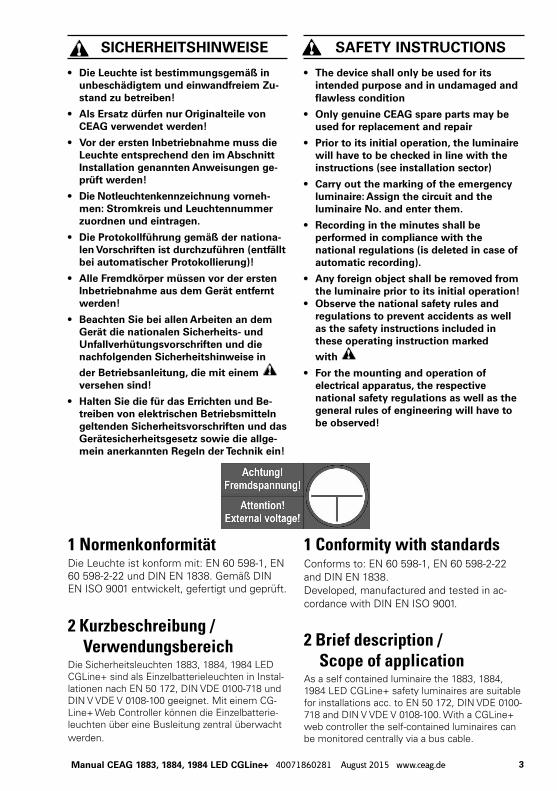
1 NormenkonformitätDie Leuchte ist konform mit: EN 60 598-1, EN 60 598-2-22 und DIN EN 1838. Gemäß DIN EN ISO 9001 entwickelt, gefertigt und geprüft.
1 Conformity with standardsConforms to: EN 60 598-1, EN 60 598-2-22 and DIN EN 1838. Developed, manufactured and tested in ac-cordance with DIN EN ISO 9001.
SiChErhEitShinwEiSE
• Die Leuchte ist bestim mungs gemäß in unbeschädigtem und einwandfreiem Zu-stand zu betreiben!
• Als Ersatz dürfen nur Originalteile von CEAG verwendet werden!
• Vor der ersten inbetriebnahme muss die Leuchte entsprechend den im Abschnitt installation genannten Anweisungen ge-prüft werden!
• Die notleuchtenkenn zeich nung vorneh-men: Stromkreis und Leuchtennummer zuordnen und eintragen.
• Die Protokollführung gemäß der nationa-len Vorschriften ist durchzuführen (entfällt bei automatischer Protokollierung)!
• Alle Fremdkörper müssen vor der ersten inbetriebnahme aus dem Gerät entfernt werden!
• Beachten Sie bei allen Ar beiten an dem Gerät die nationalen Sicherheits- und Unfallverhütungsvorschriften und die nachfolgenden Sicherheitshinweise in
der Betriebsanleitung, die mit einem versehen sind!
• halten Sie die für das Errichten und Be-treiben von elektrischen Betriebsmitteln geltenden Sicherheitsvorschriften und das Gerätesicherheitsgesetz sowie die allge-mein anerkannten regeln der technik ein!
SAFEty inStrUCtiOnS
• the device shall only be used for its intended purpose and in undamaged and flawless condition
• Only genuine CEAG spare parts may be used for replacement and repair
• Prior to its initial operation, the luminaire will have to be checked in line with the instructions (see installation sector)
• Carry out the marking of the emergency luminaire: Assign the circuit and the luminaire no. and enter them.
• recording in the minutes shall be performed in compliance with the national regulations (is deleted in case of automatic recording).
• Any foreign object shall be removed from the luminaire prior to its initial operation!
• Observe the national safety rules and regulations to prevent accidents as well as the safety instructions included in these operating instruction marked
with
• For the mounting and operation of electrical apparatus, the respective national safety regulations as well as the general rules of engineering will have to be observed!
2 Kurzbeschreibung / VerwendungsbereichDie Sicherheitsleuchten 1883, 1884, 1984 LED CGLine+ sind als Einzelbatterieleuchten in Instal-lationen nach EN 50 172, DIN VDE 0100-718 und DIN V VDE V 0108-100 geeignet. Mit einem CG-Line+ Web Controller können die Einzelbatterie-leuchten über eine Busleitung zentral überwacht werden.
2 Brief description / Scope of applicationAs a self contained luminaire the 1883, 1884, 1984 LED CGLine+ safety luminaires are suitable for installations acc. to EN 50 172, DIN VDE 0100-718 and DIN V VDE V 0108-100. With a CGLine+ web controller the self-contained luminaires can be monitored centrally via a bus cable.
4 Manual CEAG 1883, 1884, 1984 LED CGLine+ 40071860281 August 2015 www.ceag.de
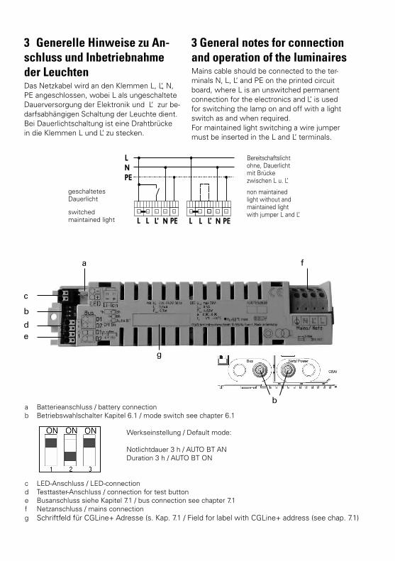
3 Generelle Hinweise zu An-schluss und Inbetriebnahme der Leuchten Das Netzkabel wird an den Klemmen L, L‘, N, PE angeschlossen, wobei L als ungeschaltete Dauerversorgung der Elektronik und L‘ zur be-darfsabhängigen Schaltung der Leuchte dient.Bei Dauerlichtschaltung ist eine Drahtbrücke in die Klemmen L und L‘ zu stecken.
3 General notes for connection and operation of the luminairesMains cable should be connected to the ter-minals N, L, L‘ and PE on the printed circuit board, where L is an unswitched permanent connection for the electronics and L’ is used for switching the lamp on and off with a light switch as and when required.For maintained light switching a wire jumper must be inserted in the L and L‘ terminals.
geschaltetesDauerlicht
Bereitschaftslicht ohne, Dauerlicht mit Brücke zwischen L u. L’
switched maintained light
non maintained light without and maintained light with jumper L and L’
f
e
c
b
b
d
g
a
a Batterieanschluss / battery connectionb Betriebswahlschalter Kapitel 6.1 / mode switch see chapter 6.1
Werkseinstellung / Default mode:
Notlichtdauer 3 h / AUTO BT AN Duration 3 h / AUTO BT ON
c LED-Anschluss / LED-connectiond Testtaster-Anschluss / connection for test buttone Busanschluss siehe Kapitel 7.1 / bus connection see chapter 7.1f Netzanschluss / mains connectiong Schriftfeld für CGLine+ Adresse (s. Kap. 7.1 / Field for label with CGLine+ address (see chap. 7.1)
5Manual CEAG 1883, 1884, 1984 LED CGLine+ 40071860281 August 2015 www.ceag.de
Busanschluss Im Falle einer zentralen Überwachung über den CGLine+ Bus, ist der Busanschluss an den Klemmen D1 und D2 vorzunehmen, wobei die Klemmen jeweils zweifach vorhan-den und geräteseitig gebrückt sind, um eine Durchverdrahtung zu ermöglichen.
LED-AnschlussDie eingebaute Versorgungselektronik ist für den Betrieb von unterschiedlichen LED-Leiterkartengeeignet. Beim ersten Einschalten bzw. nach-dem Netz und Batterie abgeklemmt waren oder nach einem Reset (Testtaster > 10 s ge-drückt) erkennt die Elektronik die verwendete Leiterkarte und stellt die zum Betrieb notwen-digen Parameter ein. Dieser Initialisierungsvor-gang dauert ca. 5 s.
LEDs sind ESD-empfindlich, d. h. gegen elekt-rostatische Entladungen, wie sie bereits beim Berühren der Anschlüsse auftreten können. Es sind geeignete Schutzmaßnahmen zu treffen!LED Leiterplatten nur im spannungslosen Zu-stand anschließen!Bei Anschluss des LED Moduls auf Polarität achten!
BatterieanschlussDie Inbetriebnahme sollte nur bei Temperatu-ren innerhalb der angegebenen Bereich erfol-gen, insbesondere das Laden der Batterien bei zu hohen oder zu niedrigen Temperaturen kann zur Schädigung der Batterien führen und wird daher von der Elektronik verhindert.Für die Nachvollziehbarkeit der Batterie-Lebensdauer bitte das Inbetriebnahme-Datum in das auf der Batterie vorgesehene Feld ein-tragen!
taster/LED-Folien-AnschlussBeim Wechsel von Taster/LED oder Leiterkarte bitte Markierung 1 auf der Leiterkarte und auf der Leiterbahnfolie beachten!
Bus connectionWith central monitoring via the CGLine+ bus, bus connection is via the D1 and D2 terminals, whereby the terminals each exist twice and are bypassed on the device side to enable through-wiring.
LED-connectionThe integrated supply electronics are suitable for the operation of various LED circuit boards. When switching on for the first time or after the network and battery have been disconnec-ted or after a reset (test button pressed > 10 s) the electronics detect the circuit board used and set the correct parameters for operation. This initialisation process requires approx. 5 s.
LEDs are sensitive against electrostatic dischar-ge. This can already happen by touching connec-tions. Please take suitable electronic protective measuresOnly connect in dead-voltage condition!
When connecting the LED module please observe the polarity!
Battery connectionCommissioning should only be carried out at temperatures within the specified range. Char-ging of the batteries at excessive or insuffici-ent temperatures may damage batteries and is therefore prevented by the electronics.To fathom batteries life please note the start-up date on the battery in the given data field!
Button/LED-foil-connectionChanging button/LED or printed circuit please see marker 1 on the printed circuit board and on the printed conductor!
6 Manual CEAG 1883, 1884, 1984 LED CGLine+ 40071860281 August 2015 www.ceag.de
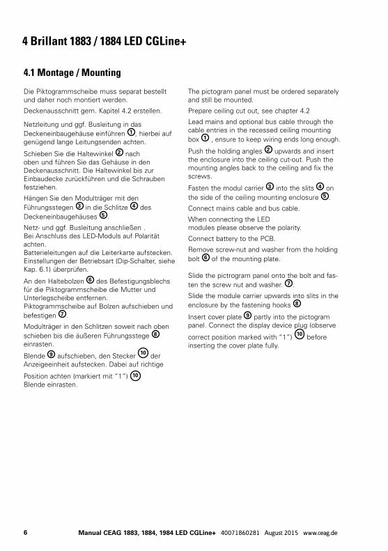
4 Brillant 1883 / 1884 LED CGLine+
4.1 Montage / Mounting
Die Piktogrammscheibe muss separat bestellt und daher noch montiert werden.
Deckenausschnitt gem. Kapitel 4.2 erstellen.
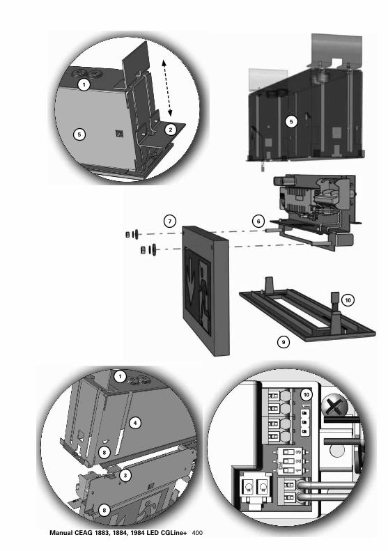
Netzleitung und ggf. Busleitung in das Deckeneinbaugehäuse einführen 1 , hierbei auf genügend lange Leitungsenden achten.
Schieben Sie die Haltewinkel 2 nach oben und führen Sie das Gehäuse in den Deckenausschnitt. Die Haltewinkel bis zur Einbaudecke zurückführen und die Schrauben festziehen.
Hängen Sie den Modulträger mit den Führungsstegen 3 in die Schlitze 4 des Deckeneinbaugehäuses 5 .
Netz- und ggf. Busleitung anschließen .Bei Anschluss des LED-Moduls auf Polarität achten.Batterieleitungen auf die Leiterkarte aufstecken.Einstellungen der Betriebsart (Dip-Schalter, siehe Kap. 6.1) überprüfen.
An den Haltebolzen 6 des Befestigungsblechs für die Piktogrammscheibe die Mutter und Unterlegscheibe entfernen. Piktogrammscheibe auf Bolzen aufschieben und befestigen 7 .
Modulträger in den Schlitzen soweit nach oben schieben bis die äußeren Führungsstege 8 einrasten.
Blende 9 aufschieben, den Stecker 10 der Anzeigeeinheit aufstecken. Dabei auf richtige
Position achten (markiert mit “1”) 10.
Blende einrasten.
The pictogram panel must be ordered separately and still be mounted.
Prepare ceiling cut out, see chapter 4.2
Lead mains and optional bus cable through the cable entries in the recessed ceiling mounting box 1 , ensure to keep wiring ends long enough.
Push the holding angles 2 upwards and insert the enclosure into the ceiling cut-out. Push the mounting angles back to the ceiling and fix the screws.
Fasten the modul carrier 3 into the slits 4 on the side of the ceiling mounting enclosure 5 .
Connect mains cable and bus cable.
When connecting the LED modules please observe the polarity.
Connect battery to the PCB.
Remove screw-nut and washer from the holding bolt 6 of the mounting plate.
Slide the pictrogram panel onto the bolt and fas-ten the screw nut and washer. 7 .
Slide the module carrier upwards into slits in the enclosure by the fastening hooks 8
Insert cover plate 9 partly into the pictogram panel. Connect the display device plug (observe
correct position marked with “1”) 10 before inserting the cover plate fully.
7Manual CEAG 1883, 1884, 1984 LED CGLine+ 40071860281 August 2015 www.ceag.de
5
5
4
3
2
1
1
8
8
67
9
10
10
1
8 Manual CEAG 1883, 1884, 1984 LED CGLine+ 40071860281 August 2015 www.ceag.de
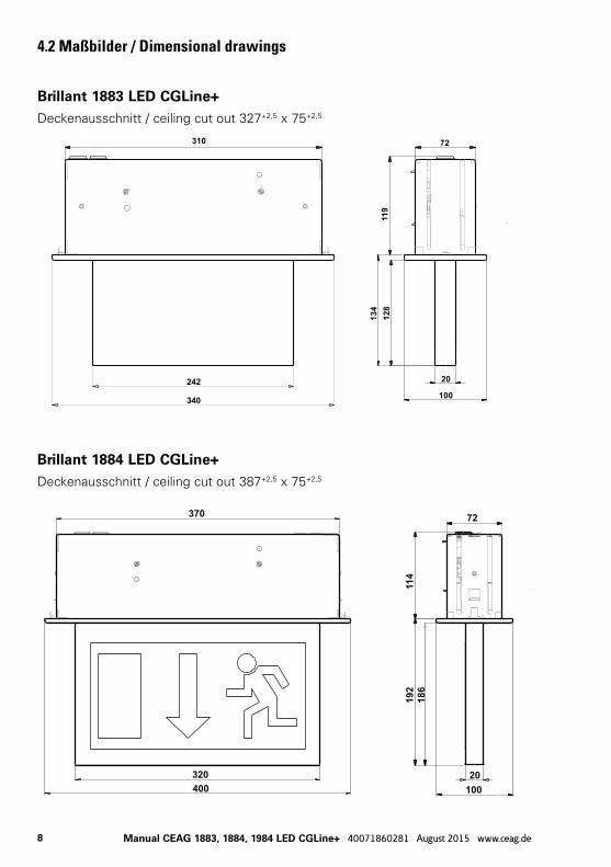
4.2 Maßbilder / Dimensional drawings
Brillant 1883 LED CGLine+Deckenausschnitt / ceiling cut out 327+2,5 x 75+2,5
Brillant 1884 LED CGLine+Deckenausschnitt / ceiling cut out 387+2,5 x 75+2,5
9Manual CEAG 1883, 1884, 1984 LED CGLine+ 40071860281 August 2015 www.ceag.de
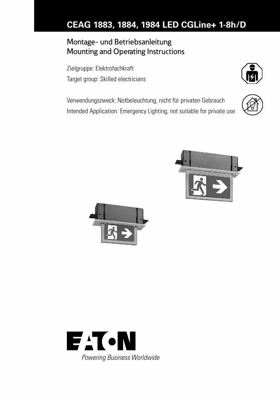
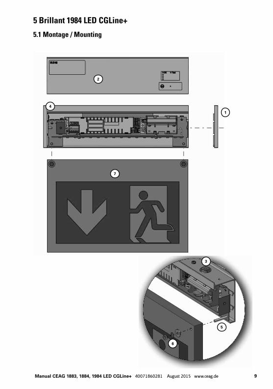
5 Brillant 1984 LED CGLine+
5.1 Montage / Mounting
1
2
3
4
6
5
7
10 Manual CEAG 1883, 1884, 1984 LED CGLine+ 40071860281 August 2015 www.ceag.de
338
9628
7
320
49
200280
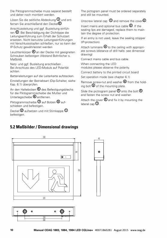
Die Piktogrammscheibe muss separat bestellt und daher noch montiert werden.
Lösen Sie die seitliche Abdeckung 1 und ent-fernen Sie anschließend den Deckel 2 .
Anschlussleitung und ggf. Busleitung einfüh-ren 3 . Bei Beschädigung der Dichtlippe die Leitungseinführung zum Erhalt der Schutzart ersetzen. Nicht benutzte Leitungseinführungen mit Verschlussstopfen schließen, nur so kann der IP-Schutz gewährleistet werden
Leuchtenkörper 4 an der Decke mit geeigneten Schrauben befestigen (Abstand Bohrlöcher s. Maßbild).
Netz- und ggf. Busleitung anschließen .Bei Anschluss des LED-Moduls auf Polarität achten.
Batterieleitungen auf die Leiterkarte aufstecken.
Einstellungen der Betriebsart (Dip-Schalter, siehe Kap. 6.1) überprüfen.
An den Haltebolzen 5 des Befestigungsblechs für die Piktogrammscheibe die Mutter und Unterlegscheibe 6 entfernen.
Piktogrammscheibe 7 auf Bolzen 5 auf-schieben und befestigen.
Deckel 2 aufsetzen und mit Stirnkappe 1 befestigen.
The pictogram panel must be ordered separately and still be mounted.
Unscrew lateral cap 1 and remove the cover 2 .
Insert mains and optional bus cable 3 . If the sealing lips are damaged, replace them to main-tain the degree of protection.
If an entry is not used, leave the sealing stopper (IP-protection).
Attach luminaire 4 to the ceiling with appropri-ate screws (distance of drill halls: see dimensial drawing)
Connect mains cable and bus cable.
When connecting the LED modules please observe the polarity.
Connect battery to the printed circuit board
Set operation mode (see chapter 6.1)
Remove screw-nut and washer 6 from the hold-ing bolt 5 of the mounting plate.
Slide the pictrogram panel 7 onto the bolt 5
and fasten the screw nut and washer.
Attach the cover 2 and fix it by mounting the lateral cap 1 .
5.2 Maßbilder / Dimensional drawings
11Manual CEAG 1883, 1884, 1984 LED CGLine+ 40071860281 August 2015 www.ceag.de
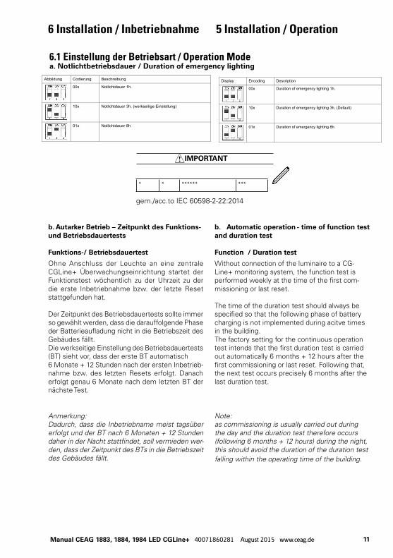
6.1 Einstellung der Betriebsart / Operation Modea. notlichtbetriebsdauer / Duration of emergency lighting
Abbildung Codierung Beschreibung
00x Notlichtdauer 1h.
10x Notlichtdauer 3h. (werkseitige Einstellung)
01x Notlichtdauer 8h.
Display Encoding Description
00x Duration of emergency lighting 1h.
10x Duration of emergency lighting 3h. (Default)
01x Duration of emergency lighting 8h.
b. Autarker Betrieb – Zeitpunkt des Funktions- und Betriebsdauertests
Funktions-/ Betriebsdauertest
Ohne Anschluss der Leuchte an eine zentrale CGLine+ Überwachungseinrichtung startet der Funktionstest wöchentlich zu der Uhrzeit zu der die erste Inbetriebnahme bzw. der letzte Reset stattgefunden hat.
Der Zeitpunkt des Betriebsdauertests sollte immer so gewählt werden, dass die darauffolgende Phase der Batterieaufladung nicht in die Betriebszeit des Gebäudes fällt. Die werkseitige Einstellung des Betriebsdauertests (BT) sieht vor, dass der erste BT automatisch 6 Monate + 12 Stunden nach der ersten Inbetrieb-nahme bzw. des letzten Resets erfolgt. Danach erfolgt genau 6 Monate nach dem letzten BT der nächste Test.
b. Automatic operation - time of function test and duration test
Function / Duration test
Without connection of the luminaire to a CG-Line+ monitoring system, the function test is performed weekly at the time of the first com-missioning or last reset.
The time of the duration test should always be specified so that the following phase of battery charging is not implemented during acitve times in the building. The factory setting for the continuous operation test intends that the first duration test is carried out automatically 6 months + 12 hours after the first commissioning or last reset. Following that, the next test occurs precisely 6 months after the last duration test.
Anmerkung:Dadurch, dass die Inbetriebname meist tagsüber erfolgt und der BT nach 6 Monaten + 12 Stunden daher in der Nacht stattfindet, soll vermieden wer-den, dass der Zeitpunkt des BTs in die Betriebszeit des Gebäudes fällt.
Note:as commissioning is usually carried out during the day and the duration test therefore occurs (following 6 months + 12 hours) during the night, this should avoid the duration of the duration test falling within the operating time of the building.
6 Installation / Inbetriebnahme 5 Installation / Operation
* * ****** ***
IMPORTANT
gem./acc.to IEC 60598-2-22:2014
12 Manual CEAG 1883, 1884, 1984 LED CGLine+ 40071860281 August 2015 www.ceag.de
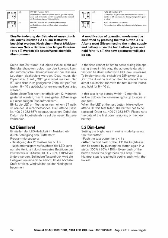
Eine Veränderung der Betriebsart muss durch ein kurzes Drücken ( < 1 s) am testtaster bestätigt werden. nach einem reset (Abklem-men von netz + Batterie oder langes Drücken ( >10 s )) werden die neuen werte ebenfalls übernommen.
A modification of operating mode must be confirmed by pressing the test button < 1 s. After a reset (Disconnecting the mains supply and battery or via the test button (press and hold for > 10 s )) the new parameter will also be set.
xx0 AUTO BT Funktion AUS der Betriebsdauertest (BT) muss manuell gestartet werden, wenn nach 12 Monaten kein BT ausgeführt wurde, wechselt die Betriebsanzeige von Grün auf Gelb
xx1 AUTO BT Funktion AN (werkseitige Einstellung) der Betriebsdauertest wird 2x pro Jahr automatisch gestartet
-
xx0 AUTO DT Function OFF Duration test (DT) has to be started manually, if about 12 months no DT was made, the display changes from green to yellow
xx1 AUTO DT Function ON (Default) The duration test will be started automatically twice a year.
-
Sollte der Zeitpunkt auf diese Weise nicht auf Betriebsruhezeiten gelegt werden können, kann der automatische Betriebsdauertest bei CGLine+ Leuchten deaktiviert werden. Dazu muss der Dipschalter 3 auf „Off“ geschaltet werden. Der BT kann dann zum geeigneten Zeitpunkt per Test-taster ( 5 – 10 s gedrückt halten) manuell gestartet werden.Sollte dieser Test nicht innerhalb von 12 Monaten gestartet werden, macht eine gelbe LED-Anzeige auf einen fälligen Test aufmerksam.Blinkt die LED am Testtaster nach einem BT gelb, wurde der BT nicht bestanden. Die Batterie (Best. Nr. 400 71 353 667) ist auszutauschen. Dabei das Datum der Inbetriebnahme auf der neuen Batterie vermerken.
6.2 DimmlevelEinstellen der LED-Helligkeit im Netzbetrieb durch Betätigung des Prüftasters:Programmiersequenz:- Betätigung des Prüftasters für t< 1 s- Nach erstmaligem Aufleuchten der LED kann nun die Helligkeit durch erneutes Betätigen des Prüftasters in 3 Stufen (100% / 30% / 10%) ver-ändert werden. Bei jedem Tastendruck wird die Helligkeit um eine Stufe erhöht. Ist die höchste Stufe erreicht, wird wieder bei der Niedrigsten begonnen.
If the time cannot be set to occur during idle ope-rating times in this way, the automatic duration test can be deactivated with CGLine+ luminaires. To implement this, switch the DIP switch 3 to ‚Off‘. The duration test can then be started manu-ally at a suitable time with the test button (press and hold for 5 – 10 s). If this test is not started within 12 months, a yellow LED on the luminaire lights up to signal a due test.When the LED at the test button blinks yellow after a DT this test failed. The battery has to be replaced (Order no. 400 71 353 667). Please note the date of the first commissioning of the new battery.
5.2 Dim-LevelSetting the brightness in mains mode by using the test button:- Push the test-button for t < 1 s- After the first flash of the LED the brightness can be altered by pushing the button again in 3 steps (100% / 30% / 10%). Every push of the button raises the brightness by 1 step. If the hightest step is reached it begins again with the lowest.
13Manual CEAG 1883, 1884, 1984 LED CGLine+ 40071860281 August 2015 www.ceag.de
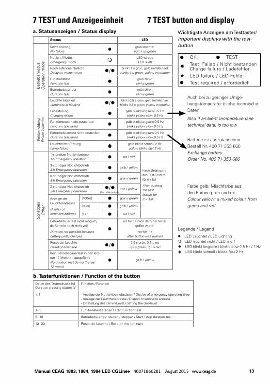
7 TEST und Anzeigeeinheit 7 TEST button and displayWichtigste Anzeigen am Testtaster/Important displays with the test-button
Status LEDB
etrie
bsm
odus
Ope
ratio
n m
ode
Keine StörungNo failure
grün leuchtetlights up green
Notlicht ModusEmergency mode
LED ist ausLED is off
Nachlaufendes NotlichtDelay on mains return / blinkt 1 s grün, gelb im Wechsel
blinks 1 s green, yellow in rotation
FunktionstestFunction test
grün blinktblinks green
BetriebsdauertestDuration test
grün blinktblinks green
Leuchte blockiertLuminaire is blocked / blinkt 0,5 s grün, gelb im Wechsel
blinks 0.5 s green, yellow in rotation
Fehl
erm
eldu
ngFa
ilure
indi
catio
n
LadestörungCharging failure
gelb blinkt langsam 0,5 Hzblinks yellow slow 0.5 Hz
Funktionstest nicht bestandenFunction test failed
gelb blinkt langsam 0,5 Hzblinks yellow slow 0.5 Hz
Betriebsdauertest nicht bestandenDuration test failed
gelb blinkt langsam 0,5 Hzblinks yellow slow 0.5 Hz
Leuchtmittel-StörungLamp failure
gelb blinkt schnell 2 Hzyellow blinks fast 2 Hz
Son
stig
esO
ther
1-stündiger Notlichtbetrieb1-h Emergency operation rot / red
Nach Betätigung des Test-Tasters für (t<1s)
After pushingthe testbutton for (t < 1s)
3-stündiger Notlichtbetrieb3-h Emergency operation gelb / yellow
8-stündiger Notlichtbetrieb8-h Emergency operation grün / green
2-stündiger Notlichtbetrieb2-h Emergency operation
/ red / yellow
Anzeige der Leuchtenadresse
Display ofluminaire address
[100er] grün / green
[10er] gelb / yellow
[1er] rot / red
Betriebsdauertest nicht möglich, da Batterie noch nicht voll
Duration not possible because battery partly charged
rot für 1s nach dem der Taster gelöst wurde
red for 1 safter button was pushed
Reset der LeuchteReset of luminaire / 0,5 s grün, 0,5 s rot
0,5 s green, 0,5 s red
Kein Betriebsdauertest in den letz-ten 12 Monaten ausgeführtNo duration test during the last 12 month
gelb / yellow
a. Statusanzeigen / Status display
b. tasterfunktionen / Function of the buttonDauer des Tastendrucks [s]Duration pressing button [s]
Funktion / Function
< 1 - Anzeige der Notlichtbetriebsdauer / Display of emergency operating time- Anzeige der Leuchtenadresse / Display of luminaire address- Einstellung des Dimm-Level / Setting the dim-level
1 - 5 Funktionstest starten / start function test
5 - 10 Betriebsdauertest starten / stoppen / Start / stop duration test
10 - 20 Reset der Leuchte / Reset of the luminaire
Legende / Legend
LED Leuchtet / LED Lighting LED leuchtet nicht / LED is off LED blinkt langsam / blinks slow 0,5 Hz / 1 Hz LED blinkt schnell / blinks fast 2 Hz
(fast alternation)
OK TESTTest: Failed / Nicht bestandenCharge failure / LadefehlerLED failure / LED-FehlerTest required / erforderlich
Auch bei zu geringer Umge-bungstemperatur (siehe technische Daten)
Also if ambient temperature (see technical data) is too low
Batterie ist auszutauschen Bestell Nr. 400 71 353 666Exchange batteryOrder No. 400 71 353 666
Farbe gelb: Mischfarbe aus den Farben grün und rotColour yellow: a mixed colour from green and red
14 Manual CEAG 1883, 1884, 1984 LED CGLine+ 40071860281 August 2015 www.ceag.de
7.1 Überwachungseinrichtung CGLine+Die Leuchten 1883, 1884, 1984 LED CGLine+ sind für den Anschluss an eine zentrale CGLine+ Überwachungseinrichtung. Jeder Leuchte der Leuchtenserie CGLine+ ist eine individuelle, unverwechselbare Identifikationsnummer mit 6 Ziffern zugeordnet.
Diese ID-Nummer muss für spätere Konfigurati-onsarbeiten in den Installationsplan übertragen werden. Dazu dient der abziehbare ID-Aufkleber in der Leuchte.
An eine zentrale CGLine+ Überwachungseinrich-tung können maximal 4 Busleitungen (2-adrig) mit jeweils bis zu 100 Leuchten angeschlossen werden. Die max. Datenleitungslänge beträgt je Strang bei 0,5 mm2 : 330 m / 1,0 mm2 : 660 m / 1,5 mm2 : 1000 mBusspannung: 22,5VDCMax.Spg.-Abfall: 13VDCBusstrom 400mA
Als Datenleitung kann eine ungeschirmte, 2-adri-ge Leitung in freier Bus-Topologie zum Einsatz kommen.Jede an der Daten-Bus-Leitung angeschlossene Leuchte wird vom CGLine+ Web-Controller au-tomatisch erkannt. Der CGLine+ Web-Controller kann den angeschlossenen Leuchten eine Kurz-adresse zuweisen, die über die drei LEDs an der Leuchte abgefragt werden kann.Weitere Informationen zur Adressierung siehe Betriebsanleitung der zentralen CGLine+ Überwa-chungseinrichtung.
7.1 Luminaire monitoring CGLine+The 1883, 1884, 1984 LED CGLine+ luminaires are prepared for connection to a central CGLine+ luminaire monitoring. An individual, distinct identification number (6 characters) is assigned to every luminaire in the CGLine+ luminaire series.
This ID number must be transferred to the installation plan for subsequent configuration work. The removable ID sticker in the luminaire can be used for this.
To central CGLine++ monitoring system maxi-mum 4 bus cables (2-core) with up to 100 lumi-naires each can be connected. The max. data line length per line is 0.5 mm2 : 330m / 1.0 mm2 : 660m / 1.5 mm2 : 1000m Bus voltage: 22,5VDCMax.voltage drop: 13VDCBus current 400mA
An unscreened, 2-core cable with free bus topo-logy can be used as a data cable.Each of the luminaires connected to the data bus cable is automatically recognised by the CGLine+ web controller. The CGLine+ web controller can assign a short address to the connected lumi-naires, which can be polled via the three LEDs on the luminaire.For more information regarding addressing please see operating instructions of a the central CG-Line+ monitoring system.
15Manual CEAG 1883, 1884, 1984 LED CGLine+ 40071860281 August 2015 www.ceag.de
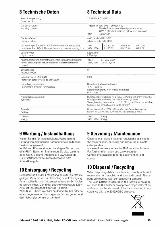
8 Technische Daten 8 Technical Data
9 Wartung / InstandhaltungHalten Sie die für Instandhaltung, Wartung und Prüfung von elektrischen Betriebsmitteln geltenden Bestimmungen ein! Im Fall von Rücksendungen benötigen Sie von uns eine RMA - Nummer. Entnehmen Sie bitte weitere Infos hierzu unserer Internetseite www.ceag.de! Für Ersatzleuchtmittel kontaktieren Sie bitte [email protected].
10 Entsorgung / RecyclingBeachten Sie bei der Entsorgung defekter Geräte die gültigen Vorschriften für Recycling und Entsorgung. Kunststoffteile sind mit entsprechenden Symbolen gekennzeichnet. Der in der Leuchte eingebaute LiIon-Akku ist - entsprechend der EU-Richtlinie 2006/66/EG - beim Wechsel an den Vertreiber oder an einen zugelassenen Entsorger zurück zu geben und darf nicht selbst entsorgt werden!
9 Servicing / MaintenanceObserve the relevant national regulations applying to the maintenance, servicing and check-ing of electri-cal apparatus ! In case of returns you need a RMA - number from us. For further information see www.ceag.de!Contact [email protected] for replacement of light source
10 Disposal / RecyclingWhen disposing of defective devices, comply with valid regulations for recycling and waste disposal. Plastic parts are marked with corresponding symbols. The LiIon battery integrated in the luminaire must be returned to the seller or an approved disposal location and must not be disposed of by the customer, in ac-cordance with the 2006/66/EC directive.
AnschlussspannungPower input
220-240 V AC, 50/60 Hz
GehäusematerialHousing material
1883/1884 Stahlblech / sheet steel, Blende Polycarbonat / bezel polycarbonate (850° C glühdratbeständig / glow wire resistant)1984 Aluminium
GehäusefarbeHousing colour
weiß, ähnlich RAL 9010white, sim. to RAL 9010
Lichtstrom phiE/phiNenn am Ende der NennbetriebsdauerLuminous flux phiE/phiNenn at the end of rated operating time
18831884, 1984
1 h 100 %1 h 85 %
3 h 46 %3 h 22 %
8 h 12%8 h 6 %
LeuchtmittelLight source
LED-LeisteLED strip
Anschlussleistung Netzbetrieb (Scheinleistung/Wirkleistung)Power consumption mains operation (apparent/effective power)
1883: 6,1 VA / 5,5 W 1884, 1984: 7,2 VA / 6,7 W
SchutzklasseInsulation class
II
Schutzart nach EN 60529Protection category acc. to EN 60529
IP20
UmgebungstemperaturPermissable ambient temperature
Dauerlicht / Maintained mode-5 °C .. +30 °CBereitschaftslicht / Non-maintained mode0 °C .. +35 °C
Netzanschlussklemmen Terminals
Durchgangsverdrahtung Netz )L,L´, N, PE) bis 2,5 mm2 (max. 6 A)Durchgangsverdrahtung CGLine+ Bus bis 1,5 mm2Through-wiring from mains ( L,L´, N, PE) up to 2.5 mm2 (max. 6 A)CGLine+ bus through-wiring up to 1.5 mm2
BatterieBattery
Lithium-Ionen 3,7 V / 2000 mAh m. Mehrfach SchutzbeschaltungLithium-Ion 3.7 V / 2000 mAh with multiple protective circuit
GewichtWeight
1883 2,9 kg1884, 1984 3,9 kg

Eatons Ziel ist es, zuverlässige, effiziente und sichere Stromversorgung dann zu bieten, wenn sie am meisten benötigt wird. Die Experten von Eaton verfügen über ein umfassendes Fachwissen im Bereich Energiemanagement in verschiedensten Branchen und sorgen so für kundens-pezifische, integrierte Lösungen, um anspruchsvollste Anforderungen der Kunden zu erfüllen.
Wir sind darauf fokussiert, stets die richtige Lösung für jede Anwendung zu finden. Dabei erwarten Entscheidungsträger mehr als lediglich innovative Produkte. Unternehmen wen-den sich an Eaton, weil individuelle Unterstützung und der Erfolg unserer Kunden stets an erster Stelle stehen. Für mehr Informationen besuchen Sie www.eaton.de.
Ihre Ansprechpartner finden Sie unter www.ceag.de.
At Eaton, we’re energized by the challenge of powering a world that demands more. With over 100 years experience in electrical power management, we have the expertise to see beyond today. From groundbreaking products to turnkey design and engineering services, critical industries around the globe count on Eaton.We power businesses with reliable, efficient and safe electrical power management solutions. Combined with our personal service, support and bold thinking, we are answering tomorrow’s needs today. Follow the charge with Eaton. Visit eaton.eu.You will find your contact partner at www.ceag.de.
EatonEMEA HeadquartersRoute de la Longeraie 71110 Morges, SwitzerlandEaton.eu
CEAG notlichtsysteme GmbhSenator-Schwartz-Ring 2659494 Soest, GermanyTel.: +49 (0) 2921 69-870Fax: +49 (0) 2921 69-617E-mail: [email protected] Web: www.ceag.de
© 2015 EatonAlle Rechte vorbehaltenPrinted in GermanyPublikations-Nr. IB451059MLBestell-Nr. 40071860281August 2015