Embed Size (px)
Citation preview
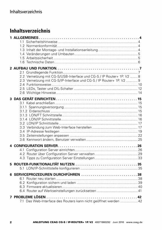
Montage- und Betriebsanleitung Mounting and Operating Instructions
Zielgruppe: Elektrofachkraft
Target group: Skilled electricians
Verwendungszweck: Notbeleuchtung, nicht für privaten Gebrauch
Intended Application: Emergency Lighting, not suitable for private use
CEAG CG-S / IP Router+ 1P. V2
2
Inhaltsverzeichnis
ANLEITUNG CEAG CG-S / IP-RoUTER+ 1P. V2 40071860292 Juni 2016 www.ceag.de
Inhaltsverzeichnis1 ALLGEMEINES . . . . . . . . . . . . . . . . . . . . . . . . . . . . . . . . . . . . . . . . . . . . . . . . . . . . 4
1.1 Sicherheitshinweise .................................................................................. 41.2 Normenkonformität ................................................................................... 41.3 Inhalt der Montage- und Installationsanleitung ......................................... 41.4 Veränderungen und Umbauten ................................................................. 51.5 Arbeitssicherheit ....................................................................................... 51.6 Technische Daten ...................................................................................... 6
2 AUFBAU UND FUNKTION. . . . . . . . . . . . . . . . . . . . . . . . . . . . . . . . . . . . . . . . . . . 72.1 Grundlegende Funktion ............................................................................. 72.2 Vernetzung mit CG-S/USB-Interface und CG-S / IP Router+ 1P. V2 ........ 82.3 Vernetzung mit CG-S/IP-Interface und CG-S / IP Router+ 1P. V2 ............ 92.4 Funktionsweise ......................................................................................... 102.5 LEDs, Taster und DIL-Schalter .................................................................. 122.6 Wichtige Hinweise .................................................................................... 14
3 DAS GERÄT EINRICHTEN . . . . . . . . . . . . . . . . . . . . . . . . . . . . . . . . . . . . . . . . . . 153.1 Kabel anschließen ..................................................................................... 153.1.1 Spannungsversorgung ............................................................................ 153.1.2 Erdanschluss .......................................................................................... 153.1.3 LON/FT Schnittstelle .............................................................................. 163.1.4 LON/IP Schnittstelle ............................................................................... 163.2 LON/IP Schnittstelle ................................................................................. 173.3 Verbindung zum Web-Interface herstellen ............................................... 173.4 IP-Adresse festlegen ................................................................................ 193.5 Zeiteinstellungen anpassen ...................................................................... 223.6 Kennwort ändern, Benutzer verwalten ..................................................... 25
4 CONFIGURATION SERVER . . . . . . . . . . . . . . . . . . . . . . . . . . . . . . . . . . . . . . . . . 264.1 Configuration Server einrichten ................................................................. 264.2 Router über Configuration Server verwalten ............................................ 294.3 Tipps zu Configuration Server Einstellungen ............................................ 33
5 ROUTER-FUNKTIONALITÄT NUTZEN . . . . . . . . . . . . . . . . . . . . . . . . . . . . . . . . 355.1 LON/IP-Schnittstelle konfigurieren ........................................................... 35
6 SERVICEPROZEDUREN DURCHFÜHREN . . . . . . . . . . . . . . . . . . . . . . . . . . . . . 386.1 Router neu starten .................................................................................... 386.2 Konfiguration sichern und laden ............................................................... 396.3 Firmware aktualisieren .............................................................................. 406.4 Router auf Werkseinstellungen zurücksetzen .......................................... 41
7 PROBLEME LÖSEN . . . . . . . . . . . . . . . . . . . . . . . . . . . . . . . . . . . . . . . . . . . . . . . 427.1 Das Web-Interface des Routers kann nicht geöffnet werden .................. 42
3
Contents
MANUAL CEAG CG-S / IP-RoUTER+ 1P. V2 40071860292 June 2016 www.ceag.de
Contents1 GENERAL INFORMATION . . . . . . . . . . . . . . . . . . . . . . . . . . . . . . . . . . . . . . . . . . . 4
1.1 Safety instructions ...................................................................................... 41.2 Conformity to standards ............................................................................ 41.3 Content of assembly and installation instructions ..................................... 41.4 Modifications and conversions .................................................................. 51.5 Work safety ................................................................................................ 51.6 Technical data ............................................................................................ 6
2 SET-UP AND FUNCTIONALITY . . . . . . . . . . . . . . . . . . . . . . . . . . . . . . . . . . . . . . . 72.1 Basic function ............................................................................................ 72.2 Networking with the CG-S/USB interface and CG-S/IP Router+ 1P. V2 .. 82.3 Networking with CG-S/IP interface and CG-S/IP Router+ 1P. V2 ............ 92.4 Operation .................................................................................................. 102.5 LEDs, push buttons and DIL switches ..................................................... 122.6 Important information ............................................................................... 14
3 SETTING UP THE DEVICE . . . . . . . . . . . . . . . . . . . . . . . . . . . . . . . . . . . . . . . . . . 153.1 Connecting the cable ................................................................................. 153.1.1 Power supply .......................................................................................... 153.1.2 Earth connection .................................................................................... 153.1.3 LON/FT interface .................................................................................... 163.1.4 LON/IP interface ..................................................................................... 163.2 LON/IP interface ....................................................................................... 173.3 Establishing a connection to the web interface ........................................ 173.4 Specifying the IP address ......................................................................... 193.5 Adapting the time settings........................................................................ 223.6 Modifying the password and managing users .......................................... 25
4 CONFIGURATION SERVER . . . . . . . . . . . . . . . . . . . . . . . . . . . . . . . . . . . . . . . . . 264.1 Setting up the configuration server ........................................................... 264.2 Managing the router via configuration server ........................................... 294.3 Tips for configuration server settings ....................................................... 33
5 USING ROUTER FUNCTIONALITY . . . . . . . . . . . . . . . . . . . . . . . . . . . . . . . . . . . 355.1 Configuring the LON/IP interface .............................................................. 35
6 IMPLEMENTING SERVICE PROCEDURES . . . . . . . . . . . . . . . . . . . . . . . . . . . . . 386.1 Restarting the router ................................................................................. 386.2 Saving and loading configuration .............................................................. 386.3 Updating firmware .................................................................................... 406.4 Resetting router to factory settings .......................................................... 41
7 TROUBLESHOOTING . . . . . . . . . . . . . . . . . . . . . . . . . . . . . . . . . . . . . . . . . . . . . . 427.1 The web interface of the router cannot be opened ................................... 42
4
Inhaltsverzeichnis
ANLEITUNG CEAG CG-S / IP-RoUTER+ 1P. V2 40071860292 Juni 2016 www.ceag.de
1 General information
1.1 Safety instructionsThis product has been constructed in accordance with valid technical regula-tions at the time of its development and manufacture and is regarded as operation-ally safe. The product may be a source of danger if not used by technically trained personnel, if used incorrectly or not according to intended use. Observe VDE and DIN standards and regulations and the safety instructions specified below.
1.2 Conformity to standardsThe IP router complies with: 72/23/EEC/ low voltage directive and 89/336/EEC/ EMC directive. Developed, manufactured and tested according to DIN EN ISO 9001.
1.3 Content of assembly and installation instructions
Persons working with this device should have read and understood the operating instructions before commencing work.
1 Allgemeines
1.1 SicherheitshinweiseDieses Produkt ist zum Zeitpunkt seiner Entwicklung und Fertigung nach gelten-den, anerkannten Regeln der Technik gebaut und gilt als betriebssicher. Es können jedoch von diesem Gefahren ausgehen, wenn es von nicht fachgerecht ausgebildetem Personal, unsachgemäß oder nicht bestimmungsgemäß verwen-det wird. Beachten Sie die Normen und Vorschriften des VDE, der DIN sowie die nachfolgenden Sicherheitshinweise!
1.2 NormenkonformitätDer IP-Router ist konform mit: 72/23/EEC/ Niederspannungsrichtlinie und 89/336/EEC/ EMC-Richtlinie. Gemäß DIN EN ISO 9001 entwickelt, gefertigt und geprüft.
1.3 Inhalt der Montage- und Installationsanleitung
Jede Person, die damit beauftragt ist, mit diesem Gerät zu arbeiten, muss die Betriebsanleitung vor Beginn der Arbeiten gelesen und verstanden haben.
5
1 Allgemeines
MANUAL CEAG CG-S / IP-RoUTER+ 1P. V2 40071860292 June 2016 www.ceag.de
1.4 Modifications and conversions
No modifications or conversions should be carried out to this device that have not been expressly permitted by the manu-facturer for avoidance of danger and for ensuring optimal efficiency.
1.5 Work safetyDamage to persons or property while working with and on this device can be avoided by complying with the specified safety instructions and other information in these operating instructions.
1.4 Veränderungen und UmbautenZur Vermeidung von Gefährdungen und zur Sicherung der optimalen Leistung, dürfen an dem Gerät weder Veränderungen noch An- oder Umbauten vorgenommen werden, die durch den Hersteller nicht ausdrücklich genehmigt worden sind.
1.5 ArbeitssicherheitDurch Befolgen der angegebenen Sicher-heitshinweise und Anweisungen in dieser Betriebsanleitung können Personen- und Sachschäden während der Arbeit mit und an dem Gerät vermieden werden.
6
Inhaltsverzeichnis
ANLEITUNG CEAG CG-S / IP-RoUTER+ 1P. V2 40071860292 Juni 2016 www.ceag.de
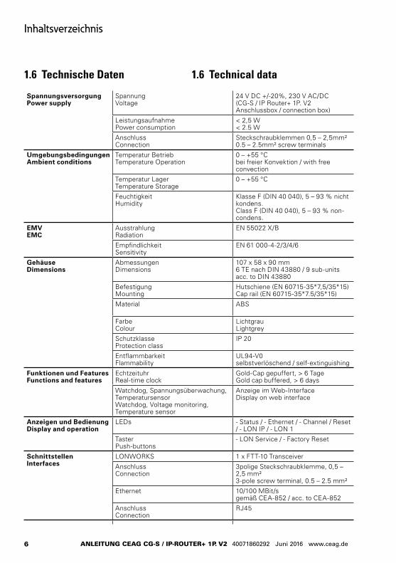
1.6 Technische Daten
Spannungsversorgung Power supply
Spannung Voltage
24 V DC +/-20%, 230 V AC/DC (CG-S / IP Router+ 1P. V2 Anschlussbox / connection box)
LeistungsaufnahmePower consumption
< 2,5 W< 2.5 W
AnschlussConnection
Steckschraubklemmen 0,5 – 2,5mm²0.5 – 2.5mm² screw terminals
UmgebungsbedingungenAmbient conditions
Temperatur BetriebTemperature Operation
0 – +55 °Cbei freier Konvektion / with free convection
Temperatur LagerTemperature Storage
0 – +55 °C
FeuchtigkeitHumidity
Klasse F (DIN 40 040), 5 – 93 % nicht kondens.Class F (DIN 40 040), 5 – 93 % non-condens.
EMVEMC
AusstrahlungRadiation
EN 55022 X/B
EmpfindlichkeitSensitivity
EN 61 000-4-2/3/4/6
GehäuseDimensions
AbmessungenDimensions
107 x 58 x 90 mm6 TE nach DIN 43880 / 9 sub-units acc. to DIN 43880
BefestigungMounting
Hutschiene (EN 60715-35*7,5/35*15)Cap rail (EN 60715-35*7.5/35*15)
Material ABS
FarbeColour
Lichtgrau Lightgrey
SchutzklasseProtection class
IP 20
EntflammbarkeitFlammability
UL94-V0selbstverlöschend / self-extinguishing
Funktionen und FeaturesFunctions and features
EchtzeituhrReal-time clock
Gold-Cap gepuffert, > 6 TageGold cap buffered, > 6 days
Watchdog, Spannungsüberwachung, TemperatursensorWatchdog, Voltage monitoring, Temperature sensor
Anzeige im Web-InterfaceDisplay on web interface
Anzeigen und BedienungDisplay and operation
LEDs - Status / - Ethernet / - Channel / Reset / - LON IP / - LON 1
TasterPush-buttons
- LON Service / - Factory Reset
SchnittstellenInterfaces
LONWORKS 1 x FTT-10 Transceiver
AnschlussConnection
3polige Steckschraubklemme, 0,5 – 2,5 mm²3-pole screw terminal, 0.5 – 2.5 mm²
Ethernet 10/100 MBit/sgemäß CEA-852 / acc. to CEA-852
AnschlussConnection
RJ45
1.6 Technical data
7
2 Set-up and functionality
MANUAL CEAG CG-S / IP-RoUTER+ 1P. V2 40071860292 June 2016 www.ceag.de
2 Set-up and functionality
2.1 Basic functionThe CG-S/IP Router+ 1P. V2 enables the IP-based networking of ZB-S, LP-STAR, AT-S+ or CG2000 emergency light systems to the CGVision visualisation software. It is thus possible to use any transmission media such as optical waveguide, WLAN etc. for which many diverse products are available on the market. The emergency light systems specified above can also be operated in mixed state at the CG-S/IP Router+ 1P. V2. The various systems only have to placed in various device groups in the CGVision software for this.
The CG-S/IP Router+ 1P. V2 features a CG-S bus port, meaning up to 64 emergency light systems behind a CG-S / IP Router+ 1P. V2 can be connected on the CG bus. The maximum length of the CG-S bus is 900 m with line topology and 320 m with free topology. The bus length or number of emergency light systems behind a CG-S/IP Router+ 1P. V2 can be expanded with optionally avail-able routers or re-peaters for the CG-S bus.
2 Aufbau und Funktion
2.1 Grundlegende FunktionDer CG-S / IP Router+ 1P. V2 ermöglicht eine IP-Basierte Vernetzung von ZB-S, LP-STAR, AT-S+ oder CG2000 Notlicht-systemen an die Visualisierungssoftware CGVision. So ist es ohne weiteres möglich, beliebige Übertragungsmedien, z. B. Lichtwellenleiter, WLAN etc. zu nutzen, für die Produkte in den vielfäl-tigsten Varianten am Markt erhältlich sind. Oben genannte Notlichtsysteme können auch gemischt am CG-S / IP Router+ 1P. V2 betrieben werden. Ledig-lich in der CGVision Software müssen die unterschiedlichen Systeme, in unterschiedliche Gerätegruppen platziert werden.
Der CG-S / IP Router+ 1P. V2 verfügt über einen CG-S Bus Port, d.h. es können bis zu 64 Notlichtsysteme hinter einen CG-S / IP Router+ 1P. V2 auf dem CG-Bus angeschlossen werden. Die max. Länge des CG-S Busses darf in Linientopologie 900m und in freier Topologie 320m betragen. Mit optional erhältlichen Routern oder Repeatern für den CG-S Bus, kann die Buslänge bzw. die Anzahl der Notlichtsysteme hinter einem CG-S / IP Router+ 1P. V2 erwei-tert werden.
8
2 Aufbau und Funktion
ANLEITUNG CEAG CG-S / IP-RoUTER+ 1P. V2 40071860292 Juni 2016 www.ceag.de
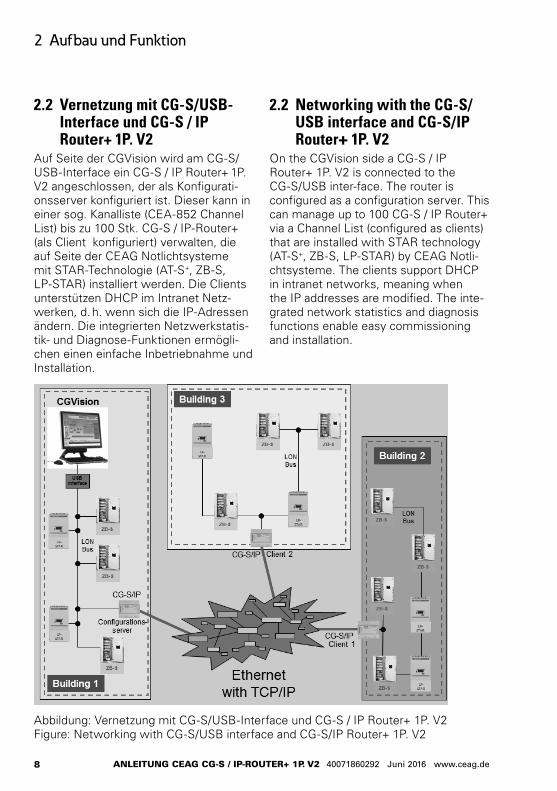
2.2 Vernetzung mit CG-S/USB-Interface und CG-S / IP Router+ 1P. V2
Auf Seite der CGVision wird am CG-S/USB-Interface ein CG-S / IP Router+ 1P. V2 angeschlossen, der als Konfigurati-onsserver konfiguriert ist. Dieser kann in einer sog. Kanalliste (CEA-852 Channel List) bis zu 100 Stk. CG-S / IP-Router+ (als Client konfiguriert) verwalten, die auf Seite der CEAG Notlichtsysteme mit STAR-Technologie (AT-S+, ZB-S, LP-STAR) installiert werden. Die Clients unterstützen DHCP im Intranet Netz-werken, d. h. wenn sich die IP-Adressen ändern. Die integrierten Netzwerkstatis-tik- und Diagnose-Funktionen ermögli-chen einen einfache Inbetriebnahme und Installation.
2.2 Networking with the CG-S/USB interface and CG-S/IP Router+ 1P. V2
On the CGVision side a CG-S / IP Router+ 1P. V2 is connected to the CG-S/USB inter-face. The router is configured as a configuration server. This can manage up to 100 CG-S / IP Router+ via a Channel List (configured as clients) that are installed with STAR technology (AT-S+, ZB-S, LP-STAR) by CEAG Notli-chtsysteme. The clients support DHCP in intranet networks, meaning when the IP addresses are modified. The inte-grated network statistics and diagnosis functions enable easy commissioning and installation.
Abbildung: Vernetzung mit CG-S/USB-Interface und CG-S / IP Router+ 1P. V2 Figure: Networking with CG-S/USB interface and CG-S/IP Router+ 1P. V2
9
2 Set-up and functionality
MANUAL CEAG CG-S / IP-RoUTER+ 1P. V2 40071860292 June 2016 www.ceag.de
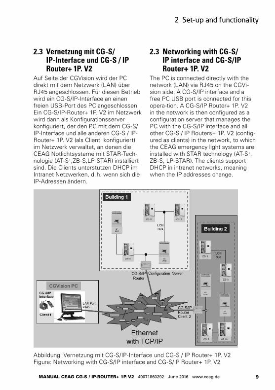
Abbildung: Vernetzung mit CG-S/IP-Interface und CG-S / IP Router+ 1P. V2 Figure: Networking with CG-S/IP interface and CG-S/IP Router+ 1P. V2
2.3 Vernetzung mit CG-S/IP-Interface und CG-S / IP Router+ 1P. V2
Auf Seite der CGVision wird der PC direkt mit dem Netzwerk (LAN) über RJ45 angeschlossen. Für diesen Betrieb wird ein CG-S/IP-Interface an einen freien USB-Port des PC angeschlossen. Ein CG-S/IP-Router+ 1P. V2 im Netzwerk wird dann als Konfigurationsserver konfiguriert, der den PC mit dem CG-S/IP-Interface und alle anderen CG-S / IP-Router+ 1P. V2 (als Client konfiguriert) im Netzwerk verwaltet, an denen die CEAG Notlichtsysteme mit STAR-Tech-nologie (AT-S+,ZB-S,LP-STAR) installiert sind. Die Clients unterstützen DHCP im Intranet Netzwerken, d. h. wenn sich die IP-Adressen ändern.
2.3 Networking with CG-S/IP interface and CG-S/IP Router+ 1P. V2
The PC is connected directly with the network (LAN) via RJ45 on the CGVi-sion side. A CG-S/IP interface and a free PC USB port is connected for this opera-tion. A CG-S/IP Router+ 1P. V2 in the network is then configured as a configuration server that manages the PC with the CG-S/IP interface and all other CG-S / IP Routers+ 1P. V2 (config-ured as clients) in the network, to which the CEAG emergency light systems are installed with STAR technology (AT-S+, ZB-S, LP-STAR). The clients support DHCP in intranet networks, meaning when the IP addresses change.
10
2 Aufbau und Funktion
ANLEITUNG CEAG CG-S / IP-RoUTER+ 1P. V2 40071860292 Juni 2016 www.ceag.de
2.4 OperationThe CG-S / IP Router+ 1P. V2 enables the CEAG CG-S bus to „tunnel“ via an existing intranet (LAN). In this way it is possible, instead of a standard bus line (CG-S bus), to use an IP-based network for transmission of data between the emergency light systems with STAR technology (AT-S+, ZB-S and LP-STAR) and the CGVision visualisation software from CEAG.
On the CGVision side the CG-S/IP interface (see above) is usually used. For this purpose two drivers (852 server / RNI client) are installed on the PC with CGVision that enable use of a LAN inter-face of the PC. The IP address of the configuration server and the own LAN IP address is entered into the 852 server configuration tool.
Any CG-S/IP Router+ 1P. V2 in the network is configured as the configura-tion server. All other CG-S/IP Routers+ 1P. V2, configured as clients, and the PC with your IP addresses, is entered and registered in a channel list in the configuration server. Setup of the ‚CG-S bus tunnel‘ is thus then complete by the IP network.
With many CG-S/IP Routers+ 1P. V2 in the network we strongly recommend significantly reducing the bus load by selecting the ‚multicast‘ operating mode, and to avoid communication faults.
Device configuration and diagnosis is carried out via the integral WEB interface. LEDs on the upper side of the housing show the status of the router interfaces. Various service functions can be triggered via push buttons.
2.4 FunktionsweiseDer CG-S / IP Router+ 1P. V2 ermöglicht den CEAG CG-S Bus durch ein vorhan-denes Intranet (LAN) zu „tunneln“. So ist es möglich, anstelle einer konventionel-len Busleitung (CG-S Bus), ein IP-Basier-tes Netzwerk zur Übertragung der Daten zwischen den Notlichtsystemen mit STAR-Technologie (AT-S+, ZB-S und LP-STAR) und der CEAG Visualisierungs-Software CGVision zu nutzen.
Auf Seite der CGVision wird hierzu in der Regel das CG-S/IP-Interface (s.o.) zum Einsatz kommen. Hierzu werden auf dem PC mit der CGVision zwei Treiber installiert (852-Server / RNI-Client) die die Nutzung einer LAN-Schnittstelle des PC ermöglichen. Im 852-Server Konfi-gurationstool wird die IP-Adresse des Konfigurationsservers und die eigene LAN IP-Adresse eingetragen.
Ein beliebiger CG-S / IP Router+ 1P. V2 im Netzwerk, wird als Konfigurationsser-ver konfiguriert. In einer „Channel-List“ im Konfigurationsserver, werden alle anderen CG-S/IP Router+ 1P. V2, als Clients konfiguriert, und der PC mit Ihren IP-Adressen eingetragen und registriert. Damit ist der „CG-S Bus Tunnel“ durch das IP-Netzwerk schon fertig eingerich-tet.
Bei vielen CG-S/IP-Routern+ 1P. V2 im Netzwerk, empfiehlt sich dringend die Betriebsart „Multicast“ um die Buslast deutlich zu reduzieren, und Kommunikati-onsstörungen zu vermeiden.
Konfiguration und Diagnose des Gerätes erfolgen über ein eingebautes Web-Interface. LEDs auf der Gehäuse-oberseite geben Aufschluss über den Status der Router Schnittstellen. Mit Hilfe von Tastern lassen sich verschiede-ne Service-Funktionen auslösen.
11
2 Set-up and functionality
MANUAL CEAG CG-S / IP-RoUTER+ 1P. V2 40071860292 June 2016 www.ceag.de
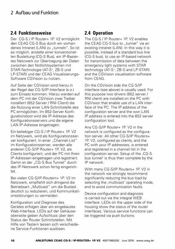
Abbildung: Der CG-S / IP Router+ 1P. V2 Figure: CG-S / IP Router+ 1P. V2
Abbildung: CG-S / IP Router+ 1P. V2 Anschlussbox
Figure: CG-S / IP Router+ 1P. V2 connection box
12
2 Aufbau und Funktion
ANLEITUNG CEAG CG-S / IP-RoUTER+ 1P. V2 40071860292 Juni 2016 www.ceag.de
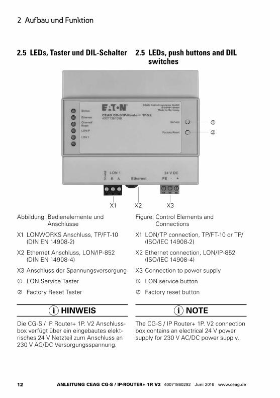
2.5 LEDs, push buttons and DIL switches
2.5 LEDs, Taster und DIL-Schalter
Abbildung: Bedienelemente und Anschlüsse
X1 LONWORKS Anschluss, TP/FT-10 (DIN EN 14908-2)
X2 Ethernet Anschluss, LON/IP-852 (DIN EN 14908-4)
X3 Anschluss der Spannungsversorgung
LON Service Taster
Factory Reset Taster
HINWEIS
Die CG-S / IP Router+ 1P. V2 Anschluss-box verfügt über ein eingebautes elekt-risches 24 V Netzteil zum Anschluss an 230 V AC/DC Versorgungsspannung.
Figure: Control Elements and Connections
X1 LON/TP connection, TP/FT-10 or TP/(ISO/IEC 14908-2)
X2 Ethernet connection, LON/IP-852 (ISO/IEC 14908-4)
X3 Connection to power supply
LON service button
Factory reset button
NOTE
The CG-S / IP Router+ 1P. V2 connection box contains an electrical 24 V power supply for 230 V AC/DC power supply.
X1 X2 X3
13
2 Set-up and functionality
MANUAL CEAG CG-S / IP-RoUTER+ 1P. V2 40071860292 June 2016 www.ceag.de
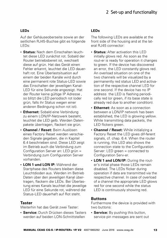
LEDs
Auf der Gehäuseoberseite sowie an der seitlichen RJ45-Buchse gibt es folgende LEDs:
• Status: Nach dem Einschalten leuch-tet diese LED zunächst rot. Sobald der Router betriebsbereit ist, wechselt diese auf grün. Hat das Gerät einen Fehler erkannt, leuchtet die LED dauer-haft rot. Eine Überlastsituation auf einem der beiden Kanäle wird durch eine permanent rote Status-LED sowie das Einschalten der jeweiligen Kanal-LED für eine Sekunde angezeigt. Hat der Router keine gültige IP Adresse , so blitzt die LED periodisch rot (oder grün, falls ihr Status wegen einer anderen Bedingung schon rot ist).
• Ethernet: Sobald eine Verbindung zu einem LON/IP-Netzwerk besteht, leuchtet die LED gelb. Werden Daten-pakete übertragen, flackert sie grün.
• Channel / Reset: Beim Auslösen eines Factory Reset werden verschie-den Signale gegeben, die in Kapitel 6.4 beschrieben sind. Diese LED zeigt im Betrieb auch die Verbindung zum Configuration Server an: LED grün = Verbindung zum Configuration Server vorhanden.
• LON 1 und LON IP: Während der Startphase des Routers bleiben diese Leuchtdioden aus. Werden im Betrieb Daten über den jeweiligen Kanal über-tragen, flackern die LEDs. Bei Überlas-tung eines Kanals leuchtet die jeweilige LED für eine Sekunde rot, während die Status-LED dauerhaft auf Rot steht.
Taster Weiterhin hat das Gerät zwei Taster:• Service: Durch Drücken dieses Tasters
werden auf beiden LON-Schnittstellen
LEDs
The following LEDs are available at the front side of the housing and at the lat-eral RJ45 connector:
• Status: After activation this LED initially glows red. As soon as the rout-er is ready for operation it changes to green. If the device has discovered an error, the LED constantly glows red. An overload situation on one of the two channels will be visualized by a permanently red status LED and activa-tion of the respective channel LED for one second. If the device has no IP address the LED is flashing periodi-cally red (or green, if its base state is already red due to another condition).
• Ethernet: As soon as a connection between a LON/IP network has been established, the LED is glowing yellow. While transmitting data packets, the LED flickers green.
• Channel / Reset: While initializing a Factory Reset the LED gives dif-ferent signals, cf. chap. 6.4. When the router is running, this LED also shows the connection state to the Configuration Server: LED green = connected to Configuration Serv-er.
• LON 1 and LON/IP: During the rout-er’s initial phase those LEDs remain disabled. The LEDs flicker during operation if data are transmitted via the respective channel. In case of overload of a channel the appropriate LED glows red for one second while the status LED is continuously showing red.
Buttons Furthermore the device is provided with two buttons: • Service: By pushing this button,
service pin messages are sent out
14
2 Aufbau und Funktion
ANLEITUNG CEAG CG-S / IP-RoUTER+ 1P. V2 40071860292 Juni 2016 www.ceag.de
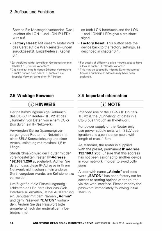
2.6 Wichtige Hinweise
HINWEIS
Der bestimmungsmäßige Gebrauch des CG-S / IP Router+ 1P. V2 ist das „Tunneln“ von Daten von einem CG-S Bus durch ein IP-Netzwerk.
Verwenden Sie zur Spannungsver-sorgung des Router nur Netzteile mit einer SELV-Kennzeichnung und einer Anschlussleitung mit maximal 1,5 m Länge.
Standardmäßig wird der Router mit der voreingestellten, festen IP-Adresse 192.168.1.250 ausgeliefert. Achten Sie darauf, dass diese IP-Adresse in Ihrem Netzwerk nicht schon an ein anderes Gerät vergeben wurde, um Kollisionen zu vermeiden.
Um Zugriff auf die Einstellungsmög-lichkeiten des Routers über das Web-Interface zu erhalten, ist bei Auslieferung ein Benutzer mit dem Namen „Admin“ und dem Passwort “EATON“ vorhan-den. Ändern Sie das Passwort bitte umgehend nach der erstmaligen Inbe-triebnahme.
2.6 Important information
NOTE
Intended use of the CG-S / IP Router+ 1P. V2 is the „tunneling“ of datas in a CG-S bus through an IP-network.
For power supply of the Router only use power supply units with SELV des-ignation and a connection cable with length of max. 1.5 m.
As standard, the router is supplied with the preset, permanent IP address 192.168.1.250. Ensure that this address has not been assigned to another device in your network in order to avoid colli-sions.
A user with name „Admin“ and pass-word „EATON“ has been factory set for access to setting options of the router via the web interface. Please modify the password immediately following initial start-up.
on both LON interfaces and the LON 1 and LON/IP LEDs give a are short signal.
• Factory Reset: This button sets the device back to the factory settings, as described in chapter 6.4.
2 For details of different device models, please have a look at Table 1 1, “Router variants”.
3 This may be caused by missing Ethernet connec-tion or a duplicate IP address may have been assigned.
2 Zur Ausführung der jeweiligen Geräteversionen s. Tabelle 1 1, „Router Varianten“
3 Das kann auf eine fehlende Ethernet Verbindung zurückzuführen sein oder z. B. auch auf die doppelte Verwen-dung einer IP Adresse.
Service Pin Messages versendet. Dazu leuchtet die LON 1 und LON IP LEDs kurz auf.
• Factory Reset: Mit diesem Taster wird das Gerät auf die Werkseinstel-lungen zurückgesetzt. Einzelheiten s. Kapitel 6.4.
15
3 Setting up the device
MANUAL CEAG CG-S / IP-RoUTER+ 1P. V2 40071860292 June 2016 www.ceag.de
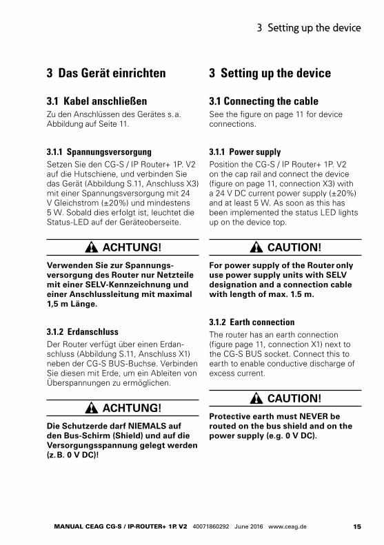
3 Setting up the device
3.1 Connecting the cableSee the figure on page 11 for device connections.
3.1.1 Power supplyPosition the CG-S / IP Router+ 1P. V2 on the cap rail and connect the device (figure on page 11, connection X3) with a 24 V DC current power supply (±20%) and at least 5 W. As soon as this has been implemented the status LED lights up on the device top.
CAUTION!
For power supply of the Router only use power supply units with SELV designation and a connection cable with length of max. 1.5 m.
3.1.2 Earth connectionThe router has an earth connection (figure page 11, connection X1) next to the CG-S BUS socket. Connect this to earth to enable conductive discharge of excess current.
CAUTION!
Protective earth must NEVER be routed on the bus shield and on the power supply (e.g. 0 V DC).
3 Das Gerät einrichten
3.1 Kabel anschließenZu den Anschlüssen des Gerätes s. a. Abbildung auf Seite 11.
3.1.1 SpannungsversorgungSetzen Sie den CG-S / IP Router+ 1P. V2 auf die Hutschiene, und verbinden Sie das Gerät (Abbildung S.11, Anschluss X3) mit einer Spannungsversorgung mit 24 V Gleichstrom (±20%) und mindestens 5 W. Sobald dies erfolgt ist, leuchtet die Status-LED auf der Geräteoberseite.
ACHTUNG!
Verwenden Sie zur Spannungs-versorgung des Router nur Netzteile mit einer SELV-Kennzeichnung und einer Anschlussleitung mit maximal 1,5 m Länge.
3.1.2 ErdanschlussDer Router verfügt über einen Erdan-schluss (Abbildung S.11, Anschluss X1) neben der CG-S BUS-Buchse. Verbinden Sie diesen mit Erde, um ein Ableiten von Überspannungen zu ermöglichen.
ACHTUNG!
Die Schutzerde darf NIEMALS auf den Bus-Schirm (Shield) und auf die Versorgungsspannung gelegt werden (z. B. 0 V DC)!
16
3 Das Gerät einrichten
ANLEITUNG CEAG CG-S / IP-RoUTER+ 1P. V2 40071860292 Juni 2016 www.ceag.de
3.1.3 LON/FT SchnittstelleDer CG-S / IP Router+ 1P. V2 verfügt über einen FTT-10 Transceiver zur Verbindung mit einem LON/FT Netz (CG-S Bus, Abbildung S.12, Anschluss X1). Schließen Sie die entsprechenden Leitungen an die Schraubklemme an. Sobald eine Verbindung erfolgreich her-gestellt werden konnte, flackert die LED LON auf der Gehäuseoberseite, wenn Daten übertragen werden.
ACHTUNG!
Stellen Sie unbedingt auch Verbindung zum Schirm an der drit-ten Klemme des LON Steckers her.
3.1.4 LON/IP SchnittstelleÜber den RJ45 Stecker (Abbildung S.12, Anschluss X2) wird der Router mit einem LON-over-IP-Netz (CEA-852) verbunden. Verwenden Sie zur Verbindung ein gewöhnliches Ethernet-Patchkabel. Der Port verfügt über eine Autosense- und Autospeed-Funktion, d. h. es wird automatisch ermittelt, ob eine Ether-net Verbindung besteht, und welche Geschwindigkeit (bis max. 100 MBit/s) verwendet wird. Sobald eine Verbindung besteht, leuchtet die LED grün bzw. gelb (bei Datenübertragung).
3.1.3 LON/FT interfaceThe CG-S / IP Router+ 1P. V2 has an FTT-10 transceiver for connection with a LON/FT network (CEA-709.3, Figure, page 12, X1 connection). Connect the corresponding cables to the screw termi-nal. As soon as a connection has been implemented successfully, the LED LON on the top housing flickers when data are transmitted.
CAUTION!
Make sure to implement a connec-tion to the shield on the third termi-nal of the LON plug.
3.1.4 LON/IP interfaceThe RJ45 plug (Figure, page 12, X2 connection) is used to connect the router to a LON-over-IP network (CEA-852). Use a standard ethernet patch cable for connection purposes. The port has an autosense and autospeed function, meaning it automatically determines whether an ethernet connection exists and which speed is used (to max. 100 MBit/s). As soon as a connection exists the LED lights up green or yellow (with data transmission).
17
3 Setting up the device
MANUAL CEAG CG-S / IP-RoUTER+ 1P. V2 40071860292 June 2016 www.ceag.de
3.2 LON/IP interfaceThe CG-S / IP Router+ 1P. V2 documen-tation, the DeviceFinder program for searching for the device via ethernet is found on the CGVision data carrier supplied.
After start of the DeviceFinder, all foun-ded devices in the network will be listed with their IP-addresses. Please not that no firewall will block the access, and broadcast messaging is allowed.
All other settings can be implemented via the integrated web interface of the router.
3.3 Establishing a connection to the web interface
Status information can be called up and other settings implemented via the web interface of the CG-S / IP Router+ 1P. V2. The web interface can be accessed by entering the IP address of the router into the web browser of a PC connected to the router. As standard, the CG-S / IP Router+ 1P. V2 is supplied with the preset IP address 192.168.1.250 and the subnet mask 255.255.255.0.
3.2 LON/IP SchnittstelleAuf dem mitgelieferten Datenträger der CGVision finden Sie die Dokumentation des CG-S / IP Router+ 1P. V2 und das Programm „DeviceFinder“ zum Suchen des Gerätes über Ethernet.
Der DeviceFinder listet alle CG-S/IP-Router+ 1P. V2 mit deren IP-Adresse auf. Beachten Sie bitte das keine Firewall den Zugriff blockiert und das Netzwerk Broadcast Abfragen zulässt.
Alle weiteren Einstellungen lassen sich über das eingebaute Web-Interface des Routers vornehmen.
3.3 Verbindung zum Web-Interface herstellenÜber das Web-Interface des CG-S / IP Router+ 1P. V2 lassen sich Statusinfor-mationen abrufen und weitere Einstellun-gen vornehmen. Auf das Web-Interface kann zugriffen werden, indem man im Webbrowser eines mit dem Router verbundenen Rechners die IP-Adresse des Routers eingibt. Standardmäßig wird der CG-S / IP Router+ 1P. V2 mit der voreingestellten IP-Adresse 192.168.1.250 und der Subnetz-Maske 255.255.255.0 ausgeliefert.
18
3 Das Gerät einrichten
ANLEITUNG CEAG CG-S / IP-RoUTER+ 1P. V2 40071860292 Juni 2016 www.ceag.de
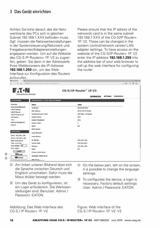
Please ensure that the IP adress of the networok card is in the same subnet 192.168.1.XXX of the CG-S/IP Router+ 1P. V2. These can be changed in the system control/network center/ LAN adapter settings. To have access on the website of the CG-S/IP-Router+ 1P. V2 enter the IP address 192.168.1.250 into the address bar of your web browser to call up the web interface for configuring the router.
Achten Sie bitte darauf, das die Netz-werkkarte des PCs sich in gleichen Subnet 192.168.1.XXX befinden muss. Ggf. müssen die Netzwerkeinstellungen in der Systemsteuerung/Netzwerk und Freigabecenter/Adaptereinstellungen angepasst werden. Um auf die Website des CG-S IP-Routers+ 1P. V2 zu zugrei-fen, geben Sie dann in der Adresszeile Ihres Webbrowsers die IP-Adresse 192.168.1.250 ein, um das Web-Interface zur Konfiguration des Routers aufzurufen.
Abbildung: Das Web-Interface des CG-S / IP Router+ 1P. V2
Am linken unteren Bildrand lässt sich die Sprache zwischen Deutsch und Englisch umschalten. Dafür muss die Maus drüber bewegt werden.
Um das Gerät zu konfigurieren, ist ein Login erforderlich. Die Werksein-stellungen sind: Benutzer: Admin /Passwort: EATON.
On the below part, left on the screen, it is possible to change the language settings.
To configurate the device, a login is necessary. Factory default settings: User: Admin / Password: EATON
Figure: Web interface of the CG-S / IP Router+ 1P. V2. V2
19
3 Setting up the device
MANUAL CEAG CG-S / IP-RoUTER+ 1P. V2 40071860292 June 2016 www.ceag.de
3.4 Specifying the IP address and Router Mode
Open the SETTINGS tab, and under CATEGORIES select “Local Area Network” on the left to modify the IP settings.
CAUTION!
A user with name „Admin“ and pass-word „EATON“ has been factory set for access to setting options of the router via the web interface. Please modify the password immediately following initial start-up.
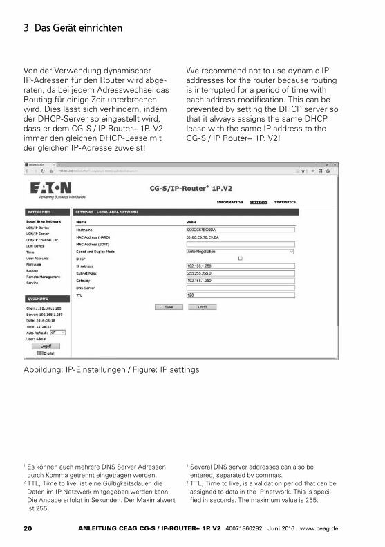
You can now enter the desired values in the fields IP Address, Subnet Mask, Gateway, DNS1 and TTL2. Alter natively, you can specify the refer-encing of dynamic IP address data via the DHCP check box. Settings are saved by clicking the Save button.
With the static IP setting the specifica-tions for the gateway and DNS server can remain empty. These are needed though when external NTP servers should be used or when remote mainte-nance is planned.
Consider that modifying the IP address of the router invalidates the existing connection to the web interface, mean-ing this must then be reestablished. If switching to DHCP has been imple-mented, then the IP address of the router must first be determined (e.g. via the IP router or the DeviceFinder).
3.4 IP-Adresse und Router-Modus festlegen
Öffnen Sie oben rechts das Menü „EINSTELLUNGEN“ und wählen Sie unter KATEGORIEN links „Local Area Network“, um die IP-Einstellungen zu ändern.
ACHTUNG!
Um Zugriff auf die Einstellungsmöglichkeiten des Routers über das Web-Interface zu erhalten, ist bei Auslieferung ein Benutzer mit dem Namen „Admin“ und dem Passwort “EATON“ ein-gerichtet. Ändern Sie das Passwort bitte umgehend nach der erstmaligen Inbetriebnahme.
In den Feldern IP-Addresse, Subnetz-maske, Gateway, DNS-Server1 und TTL2 können Sie nun die gewünschten Werte eintragen. Alternativ können Sie über die Check-Box DHCP den Bezug von dynamischen IP-Adressdaten vorgeben. Die Einstellungen werden erst beim Anklicken der Taste Save übernommen.
Bei der statischen IP-Einstellung können die Angaben zu Gateway und DNS-Server auch leer bleiben. Sie werden allerdings benötigt, wenn externe NTP-Server verwendet werden sollen oder eine Fernwartung beabsichtigt ist.
Denken Sie daran, dass durch die Ände-rung der IP-Adresse des Routers die aktuelle Verbindung zum Web-Interface verloren geht, d. h. diese muss anschlie-ßend neu aufgebaut werden. Wurde auf DHCP umgeschaltet, muss zunächst (beispielsweise über den IP-Router oder den DeviceFinder) die neue IP-Adresse des Routers ermittelt werden.
20
3 Das Gerät einrichten
ANLEITUNG CEAG CG-S / IP-RoUTER+ 1P. V2 40071860292 Juni 2016 www.ceag.de
1 Es können auch mehrere DNS Server Adressen durch Komma getrennt eingetragen werden.
2 TTL, Time to live, ist eine Gültigkeitsdauer, die Daten im IP Netzwerk mitgegeben werden kann. Die Angabe erfolgt in Sekunden. Der Maximalwert ist 255.
1 Several DNS server addresses can also be entered, separated by commas.
2 TTL, Time to live, is a validation period that can be assigned to data in the IP network. This is speci-fied in seconds. The maximum value is 255.
Abbildung: IP-Einstellungen / Figure: IP settings
Von der Verwendung dynamischer IP-Adressen für den Router wird abge-raten, da bei jedem Adress wechsel das Routing für einige Zeit unterbrochen wird. Dies lässt sich verhindern, indem der DHCP-Server so eingestellt wird, dass er dem CG-S / IP Router+ 1P. V2 immer den gleichen DHCP-Lease mit der gleichen IP-Adresse zuweist!
We recommend not to use dynamic IP addresses for the router because routing is interrupted for a period of time with each address modification. This can be prevented by setting the DHCP server so that it always assigns the same DHCP lease with the same IP address to the CG-S / IP Router+ 1P. V2!
21
3 Setting up the device
MANUAL CEAG CG-S / IP-RoUTER+ 1P. V2 40071860292 June 2016 www.ceag.de
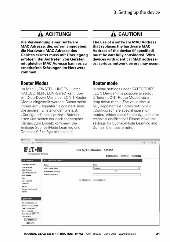
Router ModusIm Menü „EINSTELLUNGEN“ unter KATEGORIEN „LON-Gerät“ kann über ein Drop-Down Menü der LON 1 Router-Modus eingestellt werden. Dieser sollte immer auf „Repeater“ eingestellt sein! Die anderen Einstellungen wie z. B. „Configuted“ sind spezielle Betriebs-arten und sollten nur nach technischer Klärung zum Einsatz kommen! Die Einträge Subnet-/Node Learning und Domains 0 Einträge bleiben leer.
Router modeIn menu settings under CATEGORIES „LON Device“ it is possible to select different LON1 Route Modes via a drop down menu. The value should be „Repeater“! An other setting e.g. „Configured“ are special operation modes, which should are only used after technical clarification! Please leave the settings for Subnet-/Node Learning and Domain 0 entries empty.
CAUTION!
The use of a software MAC Address that replaces the hardware MAC Address of the device (if specified) must be carefully considered. With devices with identical MAC address-es, serious network errors may occur.
ACHTUNG!
Die Verwendung einer Software MAC Adresse, die, sofern angegeben, die Hardware MAC Adresse des Gerätes ersetzt muss mit Überlegung erfolgen. Bei Auftreten von Geräten mit gleicher MAC Adresse kann es zu ernsthaften Störungen im Netzwerk kommen.
22
3 Das Gerät einrichten
ANLEITUNG CEAG CG-S / IP-RoUTER+ 1P. V2 40071860292 Juni 2016 www.ceag.de
3.5 Adapting the time settingsThe CEA-852 standard recommends synchronisation of the routers to permit the detection of obsolete messages for a LON/IP network. For this purpose, synchronisation is recommended with the NTP protocol.
Both an NTP client and an NTP server are installed in the CG-S / IP Router+ 1P. V2, meaning that the device can reference the current time information from one or several NTP servers in the local network or the internet, but can also function as such a server in the local network. Simultaneous operation is possible, meaning the router can for example call up the precise time from a specific NTP server on the internet and is at the same time available locally for connected clients. If the NTP Client option is inactive, the router uses the integral time clock as a reference.
Open the SETTINGS tab, and under CATEGORIES on the left select Time to carry out the settings.
You should make sure that all devices connected with the CG-S / IP Router+ 1P. V2 and the router itself are time-synchronised.
3.5 Zeiteinstellungen anpassenDie CEA-852 Norm empfiehlt für ein LON/IP Netzwerk die Synchronisation der Router, um die Erkennung von veralteten Nachrichten zu erlauben. Dazu wird die Synchronisation über das NTP Protokoll empfohlen.
Im CG-S / IP Router+ 1P. V2 ist sowohl ein NTP-Client, als auch ein NTP-Server eingebaut, d.h. das Gerät kann die aktuellen Zeitinformationen von einem oder mehreren NTP-Servern im lokalen Netz oder dem Internet beziehen, aber auch als solcher Server im lokalen Netz fungieren. Ein gleichzeitiger Betrieb ist möglich, d. h. der Router kann beispielsweise die exakte Zeit von einem bestimmten NTP-Server im Internet abrufen und gleichzeitig lokal für ange-schlossene Clients zur Verfügung stellen. Falls die Option NTP Client abgeschaltet ist, verwendet der Router die eingebaute Echtzeituhr als Referenz.
Öffnen Sie das Menü „EINSTELLUN-GEN“ und wählen Sie unter den KATE-GORIEN links Zeit, um die Einstellungen vorzunehmen.
Sie sollten dafür sorgen, dass alle mit dem CG-S / IP Router+ 1P. V2 verbun-denen Geräte sowie der Router selbst zeitsynchronisiert werden.
23
3 Setting up the device
MANUAL CEAG CG-S / IP-RoUTER+ 1P. V2 40071860292 June 2016 www.ceag.de
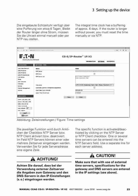
Abbildung: Zeiteinstellungen / Figure: Time settings
Die eingebaute Echtzeituhr verfügt über eine Pufferung von etwa 6 Tagen. Bleibt der Router länger ohne Strom, müssen Sie die Uhrzeit einmal manuell oder per NTP neu stellen.
The integral time clock has a buffering of approx. 6 days. If the router is longer without power, you must reset the time manually or via NTP.
The specific function is activated/deac-tivated by clicking on the NTP Server or NTP Client checkbox. One or several time servers can be entered into the NTP Servers field. Use a separate line for each server address.
CAUTION!
Make sure that with use of external time servers, specifications for the gateway and DNS servers are entered in the IP settings (see above).
Die jeweilige Funktion wird durch Ankli-cken der Checkbox NTP Server bzw. NTP Client aktiviert bzw. deaktiviert. Im Feld NTP Servers können einer oder mehrere Zeitserver eingetragen werden. Verwenden Sie für jede Serveradresse eine eigene Zeile.
ACHTUNG!
Achten Sie darauf, dass bei der Verwendung externer Zeitserver die Angaben zum Gateway und den DNS-Servern in den IP-Einstellungen (s. o.) eingetragen werden.
24
3 Das Gerät einrichten
ANLEITUNG CEAG CG-S / IP-RoUTER+ 1P. V2 40071860292 Juni 2016 www.ceag.de
Unter Local Date bzw. Local Time können Sie die gewünschte Uhrzeit bzw. das gewünschte Datum (in UTC/GMT) auch manuell eingeben. In diesem Fall darf die Funktion NTP Client nicht gewählt sein, da die Zeit sonst durch die NTP Synchronisation wieder überschrie-ben wird.
Achten Sie bitte auf die richtige Einstel-lung der Zeitzone, z. B.: UTC + 01:00, Amsterdam, Berlin, ...
Ist der Configuration Server als NTP Server aktiviert, so werden die Einstel-lungen hier überschrieben.
Die in Abbildung gezeigten Einstellungen bedeuten:• Der Router ist NTP Server für andere
Geräte• Es gilt die eingetragene Zeit• Die unter NTP Servers genannten
Server werden nicht benutzt, da bei NTP Client kein Häkchen ist.
Klicke Sie auf Save, um die Einstellun-gen zu speichern.
You can also manually enter the desired time or date (in UTC/GMT) under Local Date or Local Time. In this case the NTP Client function must not be selected as otherwise the time is overwritten again by the NTP synchronisation.
If the configuration server is activated as NTP server, the settings here are overwritten.
The settings shown in Abbildung mean:• The router is the NTP server for other
devices• The entered time is valid• The servers specified under NTP
Servers are not used because NTP Client is not ticked.
Click on Save to save the settings.
25
3 Setting up the device
MANUAL CEAG CG-S / IP-RoUTER+ 1P. V2 40071860292 June 2016 www.ceag.de
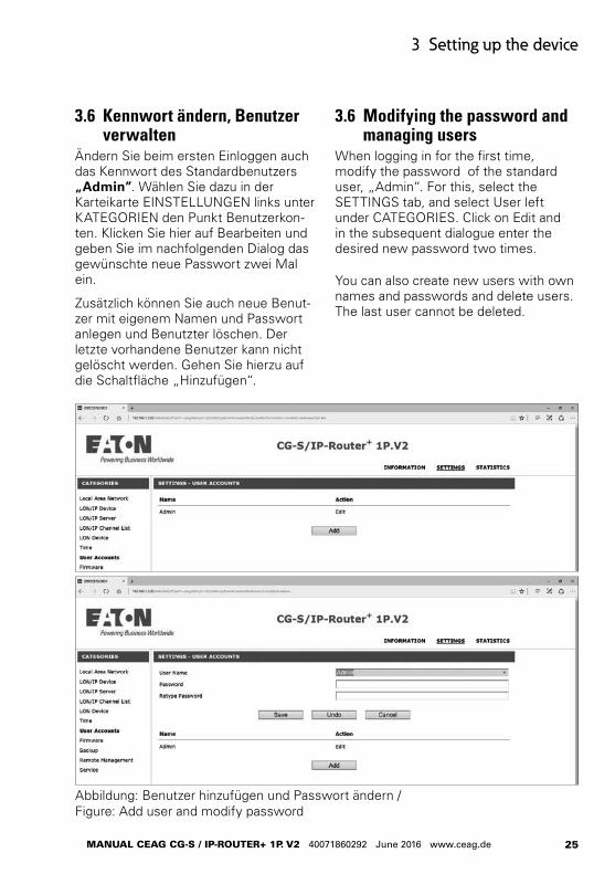
Abbildung: Benutzer hinzufügen und Passwort ändern / Figure: Add user and modify password
3.6 Kennwort ändern, Benutzer verwalten
Ändern Sie beim ersten Einloggen auch das Kennwort des Standardbenutzers „Admin”. Wählen Sie dazu in der Karteikarte EINSTELLUNGEN links unter KATEGORIEN den Punkt Benutzerkon-ten. Klicken Sie hier auf Bearbeiten und geben Sie im nachfolgenden Dialog das gewünschte neue Passwort zwei Mal ein.
Zusätzlich können Sie auch neue Benut-zer mit eigenem Namen und Passwort anlegen und Benutzter löschen. Der letzte vorhandene Benutzer kann nicht gelöscht werden. Gehen Sie hierzu auf die Schaltfläche „Hinzufügen“.
3.6 Modifying the password and managing users
When logging in for the first time, modify the password of the standard user, „Admin“. For this, select the SETTINGS tab, and select User left under CATEGORIES. Click on Edit and in the subsequent dialogue enter the desired new password two times.
You can also create new users with own names and passwords and delete users. The last user cannot be deleted.
26
4 Configuration Server
ANLEITUNG CEAG CG-S / IP-RoUTER+ 1P. V2 40071860292 Juni 2016 www.ceag.de
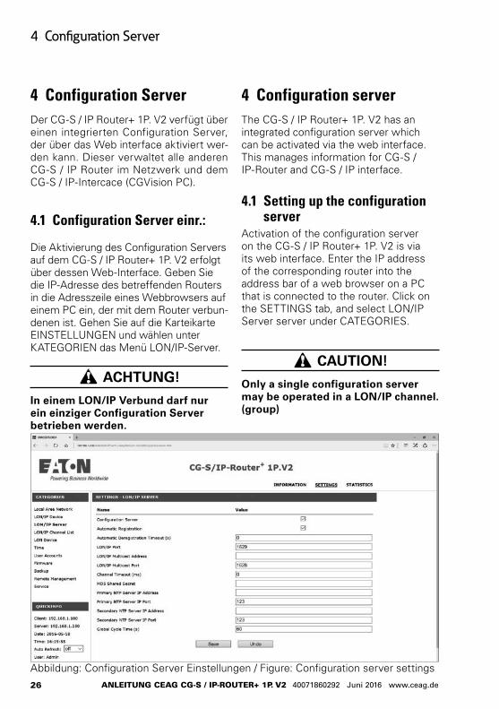
4 Configuration serverThe CG-S / IP Router+ 1P. V2 has an integrated configuration server which can be activated via the web interface. This manages information for CG-S / IP-Router and CG-S / IP interface.
4.1 Setting up the configuration server
Activation of the configuration server on the CG-S / IP Router+ 1P. V2 is via its web interface. Enter the IP address of the corresponding router into the address bar of a web browser on a PC that is connected to the router. Click on the SETTINGS tab, and select LON/IP Server server under CATEGORIES.
CAUTION!
Only a single configuration server may be operated in a LON/IP channel. (group)
4 Configuration ServerDer CG-S / IP Router+ 1P. V2 verfügt über einen integrierten Configuration Server, der über das Web interface aktiviert wer-den kann. Dieser verwaltet alle anderen CG-S / IP Router im Netzwerk und dem CG-S / IP-Intercace (CGVision PC).
4.1 Configuration Server einr.:
Die Aktivierung des Configuration Servers auf dem CG-S / IP Router+ 1P. V2 erfolgt über dessen Web-Interface. Geben Sie die IP-Adresse des betreffenden Routers in die Adresszeile eines Webbrowsers auf einem PC ein, der mit dem Router verbun-denen ist. Gehen Sie auf die Karteikarte EINSTELLUNGEN und wählen unter KATEGORIEN das Menü LON/IP-Server.
ACHTUNG!
In einem LON/IP Verbund darf nur ein einziger Configuration Server betrieben werden.
Abbildung: Configuration Server Einstellungen / Figure: Configuration server settings
27
4 Configuration server
MANUAL CEAG CG-S / IP-RoUTER+ 1P. V2 40071860292 June 2016 www.ceag.de
Der Configuration Server wird durch ein Häkchen in der entsprechenden Check-box aktiviert.
Automatische Registrierung: Ist dieser Modus gewählt, so werden LON/IP Geräte, die sich beim Con-figuration Server melden registriert. Sie werden aber automatisch wieder entfernt, falls sie sich nicht innerhalb des Automatic Deregistration Timeout wieder melden.Das Zeitintervall wird in Sekunden angegeben (Default = 0s).
LON/IP-Port: Dies ist der Port über den der Configu-ration Server erreichbar ist (Default = 1629, gemäß CEA-852 Standard).
ACHTUNG!
Wird dieser Wert geändert, so muss dies für alle Geräte auf dem LON/IP Kanal identisch eingestellt werden.
Festlegungen von Unicast und Multicast Adressen auf dem Configuration Server überschreiben die Einstellungen auf einzelnen Geräten.
LON/IP-Multicast Adresse und Port: Über die IP Multicast-Adressierung lassen sich LON-Pakete parallel an mehrere Empfänger auf dem LON/IP Kanal senden. Dies trägt erheblich zur Reduzierung der Netzwerklast bei. Multi-cast Adressierung ist insbesondere zu empfehlen, wenn kein Channel Routing möglich ist.
ACHTUNG!
Alle Teilnehmer eines LON/IP-Kanals müssen dieselbe Multicast-Adresse und dieselbe Port-Nummer nutzen.
The configuration server is activated by ticking the corresponding checkbox.
Automatic registration: If this mode is selected, LON/IP report-ing with the configuration server are registered. These are automatically deleted again though if they do not regis-ter automatically within the Automatic Deregistration Timeout. the time interval is specified in seconds (default = 0s).
LON/IP Port: This is the port via which the configura-tion server is reached (default = 1629, according to CEA-852 standard ).
CAUTION!
If this value is modified this has to be set identically for all devices on the LON/IP channel.
Settings for unicast and multicast addresses on the configuration server overwrite the settings on indi-vidual devices.
LON/IP Multicast address and port: LON packets can be sent in parallel on the LON/IP channel to several recipients via the IP multicast addressing. This contributes significantly to reduction of network load. Multicast addressing is recommended especially when no chan-nel routing is possible.
CAUTION!
All participants in a LON/IP chan-nel should use the same multicast address and the same port number.
28
4 Configuration Server
ANLEITUNG CEAG CG-S / IP-RoUTER+ 1P. V2 40071860292 Juni 2016 www.ceag.de
Channel-Timeout: Mit dem Channel Timeout werden verspätete IP Pakete erkannt. Wird hier ein Wert angegeben, dann müssen alle Devices im Netz genau die glei-che Uhrzeit haben. Der Wert wird in Millisekunden zwischen 1 und 1500 angegeben.
Die Default Einstellung 0 bedeutet, dass diese Überwachung ausgeschaltet ist.
MD5-Schlüssel: Dieses Feld enthält den Schlüssel, falls eine MD5 Authentifizierung verwendet werden soll. Bleibt das Feld leer, ist die Authentifizierung ausgeschaltet. Wird die Authentifizierung eingesetzt, so ist zu prüfen, ob alle Geräte dies auch unterstützen.
NTP Server (Primäre + Sekundäre): Zeitkonsistenz ist wichtig im Netzbetrieb. Deshalb ist die Verwendung eines NTP Servers empfohlen. Der CG-S / IP Router+ 1P. V2 kann selbst als solcher konfiguriert werden (s. Abschnitt 3.5). Es wird empfohlen, den Configuration Server auch zum NTP Server zu machen. Dann ist eine synchrone Zeit gewährleis-tet und es müssen sich nicht alle Geräte die Zeit aus dem Internet holen.
Sollen NTP Server verwendet werden so sind deren IP Adressen hier anzuge-ben. Dies ist auch erforderlich, falls der interne NTP Server des Geräts benutzt werden soll. Der Standard NTP Port ist 123.
Globale Zykluszeit: Zeitintervall in Sekunden in dem die LON/IP Geräte abgefragt werden, um ihr Vorhanden sein zu überprüfen. (Default = 60). Mit dem Wert 0 wird die zyklische Prüfung abgeschaltet.
Channel timeout: Delayed IP packets are identified with the Channel Timeout. If a value is specified here, all devices in the network must have exactly the same time. The value is specified in milliseconds between 1 and 1500.
The 0 default setting means that this monitoring is deactivated.
MD5 Shared Secret: This field contains the key in case a MD5 authentication should be used. If the field remains empty, authentication is deactivated. If authentication is used, check whether all devices support this.
NTP server (primary + secondary): Time consistency is important with network operation. This is why use of an NTP server is recommended. The CG-S / IP Router+ 1P. V2 can itself be configured as one. (see section 3.5). We recommend making the configuration server the NTP server. This ensures synchronous time and not all devices have to reference the time from the internet.
If NTP servers are to be used their IP addresses must be specified here. This is also requi red if the internal NTP server of the device is to be used. The standard NTP port is 123.
Global Cycle Time: Time interval in seconds in which the LON/IP devices are queried to check their existence. (Default = 60). Cyclic checking is deactivated with the value 0.
29
4 Configuration server
MANUAL CEAG CG-S / IP-RoUTER+ 1P. V2 40071860292 June 2016 www.ceag.de
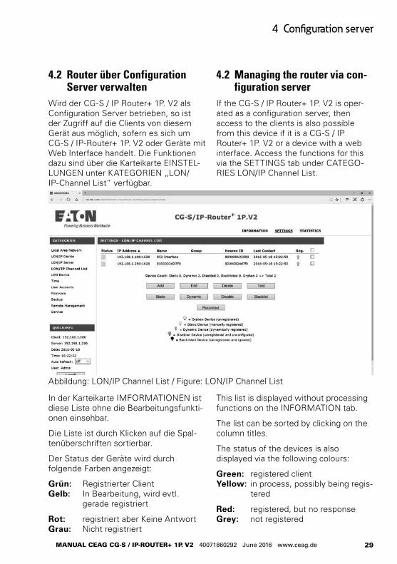
Abbildung: LON/IP Channel List / Figure: LON/IP Channel List
4.2 Managing the router via con-figuration server
If the CG-S / IP Router+ 1P. V2 is oper-ated as a configuration server, then access to the clients is also possible from this device if it is a CG-S / IP Router+ 1P. V2 or a device with a web interface. Access the functions for this via the SETTINGS tab under CATEGO-RIES LON/IP Channel List.
4.2 Router über Configuration Server verwalten
Wird der CG-S / IP Router+ 1P. V2 als Configuration Server betrieben, so ist der Zugriff auf die Clients von diesem Gerät aus möglich, sofern es sich um CG-S / IP-Router+ 1P. V2 oder Geräte mit Web Interface handelt. Die Funktionen dazu sind über die Karteikarte EINSTEL-LUNGEN unter KATEGORIEN „LON/IP-Channel List“ verfügbar.
This list is displayed without processing functions on the INFORMATION tab.
The list can be sorted by clicking on the column titles.
The status of the devices is also displayed via the following colours:
Green: registered client Yellow: in process, possibly being regis-
tered
Red: registered, but no response Grey: not registered
In der Karteikarte IMFORMATIONEN ist diese Liste ohne die Bearbeitungsfunkti-onen einsehbar.
Die Liste ist durch Klicken auf die Spal-tenüberschriften sortierbar.
Der Status der Geräte wird durch folgende Farben angezeigt:
Grün: Registrierter Client Gelb: In Bearbeitung, wird evtl.
gerade registriert
Rot: registriert aber Keine Antwort Grau: Nicht registriert
30
4 Configuration Server
ANLEITUNG CEAG CG-S / IP-RoUTER+ 1P. V2 40071860292 Juni 2016 www.ceag.de
Klicken auf die IP Adresse eine Gerätes öffnet das Web Interface dieses Gerätes, so dass an ihm Einstellungen verändert werden können.
In der Spalte Name wird standardmäßig die Basic Node-ID des Gerätes angegeben. Hier kann auch ein sprechender Name eingetragen werden, der aber eindeutig sein muss. Hierfür muss rechts das Häck-chen gesetzt werden. Über „Bearbeiten“ kann nur der Name geändert werden.
Die Spalte Gruppe ist ein zusätzliches Ordnungskriterium der Liste. Damit lassen sich Geräte noch einfacher in großen Listen verwalten. Für den Betrieb des Configura-tion Server hat dies keine Auswirkungen.
Die Symbole in der Flag Spalte der Liste zeigen den aktuellen Zustand jedes Gerätes in Bezug auf den Configuration Server an.
Verwaistes Gerät: Das Gerät wurde im Netz gefun-den, ist aber nicht registriert
Statisches Gerät: Das Gerät wurde manuell als permanentes Gerät registriert.
Dynamisches Gerät: Das Gerät hat sich automatisch selbst am Configuration Server registriert
Deaktiviertes Gerät: Das Gerät ist vorübergehend deak-tiviert, d.h. es erhält keine Nach-richten mehr über den CEA-852 Channel.
Gespertes Gerät: Das Gerät ist manuell als Teilneh-mer deaktiviert, Automatische Anmeldungen werden nicht mehr akzeptiert und es werden ihm keine Informationen über andere Geräte geliefert.
Clicking on the IP address of a device opens its the web interface for modify-ing settings to the device.
The basic node-ID of the device is speci-fied as standard in the Name column. A corresponding name can be entered. This must be unique.
The Group column is an additional management criterion of the list. This makes it easier to manage devices in large lists. This does not affect operation of the configuration server.
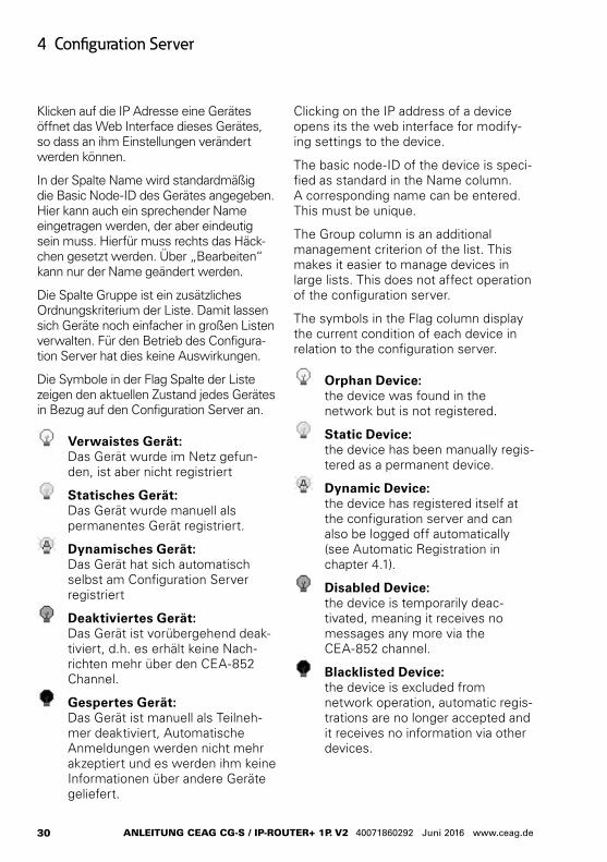
The symbols in the Flag column display the current condition of each device in relation to the configuration server.
Orphan Device: the device was found in the network but is not registered.
Static Device: the device has been manually regis-tered as a permanent device.
Dynamic Device: the device has registered itself at the configuration server and can also be logged off automatically (see Automatic Registration in chapter 4.1).
Disabled Device: the device is temporarily deac-tivated, meaning it receives no messages any more via the CEA-852 channel.
Blacklisted Device: the device is excluded from network operation, automatic regis-trations are no longer accepted and it receives no information via other devices.
31
4 Configuration server
MANUAL CEAG CG-S / IP-RoUTER+ 1P. V2 40071860292 June 2016 www.ceag.de
The command buttons below the list have the following meaning, referring specifically to the selected devices:
Add A further router can be manually entered into the list.
Edit IP address, port. Name and group affilia-tion can be edited.
Delete The device is deleted from the list, meaning it receives no information via other devices and no longer participates in the communication.
Test Device status is tested and the test result is displayed above the list.
Static Changes the devices selected to perma-nently registered devices. This is of inter-est for devices that have been added via Automatic Registration during commis-sioning. These can be then rapidly changed to static devices for which no de-registration takes place.
Die Befehlsschaltflächen unter der Liste haben folgende Bedeutung, die sich jeweils auf die ausgewählten Geräte bezieht:
Hinzufügen Ein weiterer Router kann manuell in die Liste eingetragen werden.
Bearbeiten IP-Adresse, Port. Name und Gruppenzu-gehörigkeit können bearbeitet werden.
Löschen Das Gerät wird aus der Liste gelöscht, d.h. es erhält keine Information über andere Geräte und nimmt dann an der Kommunikation nicht mehr teil.
Testen Der Status des Gerätes wird geprüft und das Ergebnis des Test wird oberhalb der Liste angezeigt.
Statisch Macht aus den ausgewählten Geräten fest registrierte Geräte. Das ist bei Gerä-ten interessant, die bei der Inbetriebnah-me durch Automatic Registration dazu gekommen sind. Diese kann man dann schnell zu statischen Geräten machen, für die auch keine Deregistrierung mehr erfolgt.
32
4 Configuration Server
ANLEITUNG CEAG CG-S / IP-RoUTER+ 1P. V2 40071860292 Juni 2016 www.ceag.de
Dynamisch Das Gerät wird in einen Zustand ver-setzt, der der Automatic Registration entspricht, d. h. meldet es sich nicht innerhalb des festgelegten Automatic Deregistration Timeout, so wird es von der Liste der registrierten Geräte gestri-chen.
Deaktiviert Die CEA-852 Channel Kommunikation des Gerätes wird vorübergehend deak-tiviert. Das Gerät bleibt registriert und ziegt auch an, dass es mit dem Configu-ration Server in Verbindung ist. Mit den Befehlen Static oder Dynamic kann es wieder aktiviert werden
Gesperrt Anmeldungen von einem Gerät mit dieser IP Adresse werden nicht mehr akzeptiert.
Kontaktieren Der Configuration Server verwirft die über die Geräte vorhandenen Daten und baut die Liste der registrierten Geräte mit allen Daten neu auf.
Dynamic The device is set to a condition corre-sponding to Automatic Registration, meaning if it does not register within the specified Automatic Deregistration Timeout, it is deleted from the list of registered devices.
Disable The CEA-852 channel communication of the device is temporarily deactivated. The device remains registered and also shows that it is connected to the configu-ration server. Use the Static or Dynamic commands to reactivate it.
Blacklist Registrations from a device with this IP address are no longer accepted.
Recontact The configuration server rejects the device data and reconstructs the list of registered devices with all data.
33
4 Configuration server
MANUAL CEAG CG-S / IP-RoUTER+ 1P. V2 40071860292 June 2016 www.ceag.de
4.3 Tips for configuration server settings
Channel Timeout, danger of data loss
The Channel Timeout should be deac-tivated (= 0). If it is set too briefly, it may cause the loss of data packets. The precision of time synchronisation between the participating routers is of importance here: if Channel Timeout is for example less than the possible differ-ence between device times, this will definitely cause data loss.
Multicast addressing, reduction of bus load
If many devices exist in the network, this is the preferred method of addressing as it reduces bus load. A further possibility for reducing bus load is Time To Live, in this case the definable IP TTL under LON/IP Device. This limits the number of routers over which a data packet can be forwarded until its validity expires. Appropriate values for this can be derived from the network structure (perhaps ask the network administrator) or can be defined empirically.
Automatic Registration, rapid commissioning
Automatic Registration is the best method to rapidly ascertain all LON/IP devices in the network. With aid of the commands available under LON/IP Chan-nel List, the status of the devices can be set to Static, or unwanted devices can be removed from the communication via Disable or Blacklist. Automatic Registra-tion can then be terminated for normal operation.
4.3 Tipps zu Configuration Server Einstellungen
Channel Timeout, Gefahr von Daten-verlust
Das Channel Timeout sollte ausgeschal-tet sein (= 0). Ist es zu kurz eingestellt, so kann dies zum Verlust von Daten-paketen führen. Die Genauigkeit der Zeitsynchronisierung zwischen den beteiligten Routern spielt dabei eine Rolle: Ist das Channel Timeout z. B. klei-ner als die mögliche Differenz zwischen den Gerätezeiten, so kommt es sicher zu Datenverlusten.
Multicast Adressierung, Reduzierung der Buslast
Sind viele Geräte im Netzwerk vorhan-den, so ist dies die bevorzugte Adressie-rungsmethode, da sie die Busbelastung reduziert. Eine weitere Möglichkeit die Buslast zu reduzieren ist die Time To Live, in die-sem Fall die unter LON/IP Device fest-legbare IP TTL. Sie begrenzt die Anzahl der Router über die ein Datenpaket weitergereicht wird, bis seine Gültigkeit verfällt. Sinnvolle Werte hierfür ergeben sich aus der Netzwerkstruktur (evtl. den Netzwerkadministrator fragen) oder sie sind empirisch zu bestimmen.
Automatische Registrierung, schnelle Inbetriebnahme
Um schnell alle LON/IP Geräte im Netz zu erfassen, ist die Automatic Registrati-on die beste Vorgehensweise. Mit Hilfe der unter LON/IP Channel List verfüg-baren Kommandos kann der Status der Geräte dann auf Static gesetzt werden oder unerwünschte Geräte können mit
34
4 Configuration Server
ANLEITUNG CEAG CG-S / IP-RoUTER+ 1P. V2 40071860292 Juni 2016 www.ceag.de
Disable oder Blacklist aus der Kommu-nikation herausgenommen werden. Danach kann die Automatic Registration für den normalen Betrieb wieder been-det werden.
Deaktiviert oder gesperrt
Von Geräten mit Status gesperrt werden im Automatic Registration Betrieb keine Anmeldungen mehr angenommen, deaktivierte Geräte erhalten zwar keine Informationen mehr und können deshalb keine Meldungen weiterleiten, sind aber weiterhin registriert und unterliegen insbesondere dem Automatic Deregistra-tion Timeout. Mit dem gesperrt Befehl können also Geräte aus dem System ausgeschlossen werden. Mit deaktivieren kann der IP Kanal eines Gerätes, z. B. zu Testzwe-cken, zeitweise für das Gesamtsystem gesperrt werden.
Disable or Blacklist
In Automatic Registration mode, messages from devices with Blacklist status are no longer accepted. Disabled devices no longer receive information and can therefore no longer forward messages, but continue to be registered and are still subject to the Automatic Deregistration Timeout. Devices can thus be excluded from the system with the Blacklist command. The IP channel of a device can be temporar-ily locked for the complete system, for example for testing purposes, with Disable.
35
5 Using router functionality
MANUAL CEAG CG-S / IP-RoUTER+ 1P. V2 40071860292 June 2016 www.ceag.de
5 Using router functionality
5.1 Configuring the LON/IP interface
Configuration of the CEA-852 interface is via the web interface of the CG-S / IP Router+ 1P. V2. Enter the IP address of the router into the address bar of a web browser on a PC that is connected to the router. Click on the SETTINGS tab, and select LON/IP Device under CATEGO-RIES.
5 Router-Funktionalität nutzen
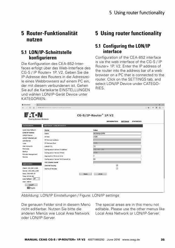
5.1 LON/IP-Schnittstelle konfigurieren
Die Konfiguration des CEA-852-Inter-faces erfolgt über das Web-Interface des CG-S / IP Router+ 1P. V2. Geben Sie die IP-Adresse des Routers in die Adresszei-le eines Webbrowsers auf einem PC ein, der mit diesem verbundenen ist. Gehen Sie auf die Karteikarte EINSTELLUNGEN und wählen LON/IP-Gerät Device unter KATEGORIEN.
Abbildung: LON/IP Einstellungen / Figure: LON/IP settings
Die genauen Felder sind in diesem Menü nicht editierbar. Nutzen Sie bitte die anderen Menüs wie Local Area Network oder LON/IP-Server.
The special areas are in this menu not editable. Please use the other menus like Local Area Network or LON/IP-Server.
36
5 Router-Funktionalität nutzen
ANLEITUNG CEAG CG-S / IP-RoUTER+ 1P. V2 40071860292 Juni 2016 www.ceag.de
ACHTUNG!
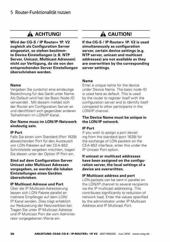
Wird der CG-S / IP Router+ 1P. V2 zugleich als Configuration Server eingesetzt, so stehen bestimm-te Device Einstellungen (z. B. NTP Server, Unicast, Multicast Adressen) nicht zur Verfügung, da sie von den entsprechenden Server Einstellungen überschrieben werden.
Name Vergeben Sie zunächst eine eindeutige Bezeichnung für das Gerät unter Name. Als Default wird hier die Basic Node-ID verwendet . Mit diesem meldet sich der Router am Configuration Server an und identifiziert sich gegenüber anderen Teilnehmern im LON/IP-Kanal.
Der Name muss im LON/IP-Netzwerk eindeutig sein.
IP Port Falls Sie einen vom Standard (Port 1628) abweichenden Port für den Austausch von LON-Paketen auf der CEA-852 Schnittstelle vergeben möchten, tragen Sie diesen unter der Option IP Port ein.
Sind auf dem Configuration Server Unicast oder Multicast Adressen vorgegeben, so werden die lokalen Eintstellungen eines Gerätes überschrieben.
IP Multicast Adresse und Port Über die IP Multicast-Adressierung lassen sich LON-Pakete parallel an mehrere Empfänger auf dem LON/IP Kanal senden. Dies trägt erheblich zur Reduzierung der Netzwerklast bei. Tragen Sie unter IP Multicast Adresse und IP Multicast Port die vom Administ-rator vorgegebenen Werte ein.
CAUTION!
If the CG-S / IP Router+ 1P. V2 is used simultaneously as configuration server, certain device settings (e.g. NTP server, unicast and multicast addresses) are not available as they are overwritten by the corresponding server settings.
Name Enter a unique name for the device under Device Name. The basic node-ID is used here as default. This is used by the router to register itself with the configuration server and to identify itself compared to other participants in the LON/IP channel.
The Device Name must be unique in the LON/IP network.
IP Port If you wish to assign a port deviat-ing from the standard (port 1628) for the exchange of LON packets on the CEA-852 interface, enter this under the IP Unicast Port option.
If unicast or multicast addresses have been assigned on the configu-ration server, the local settings of a device are overwritten.
IP Multicast address and port LON packets can be sent in parallel on the LON/IP channel to several recipients via the IP multicast addressing. This contributes significantly to reduction of network load. Enter the values specified by the administrator under IP Multicast Address and IP Multicast Port.
37
5 Using router functionality
MANUAL CEAG CG-S / IP-RoUTER+ 1P. V2 40071860292 June 2016 www.ceag.de
Configuration Server Ein LON/IP-Kanal wird in der Regel über einen Configuration Server verwaltet, Ein solcher ist im CG-S / IP-Router+ 1P. V2 integriert und kann über die Karteikarte EINSTELLUNGEN > KATEGORIEN > LON/IP-Server aktiviert werden.
Tragen Sie die Adresse des CG-S / IP-Router+ 1P. V2 ein, auf dem der Confi-guration Servers läuft, sowie den Port (1629 nach CEA-852 Standard). Wird der Configuration Server auf demselben Gerät betrieben, so ist hier kein Eintrag möglich.
Anhand der folgenden Punkte können Sie kontrollieren, ob die Zuweisung des Configuration Servers erfolgreich war:
1. Die Status/Reset LED leuchtet grün.
2. Im Web-Interface des Routers ist unter Statistiken > LON/IP-Gerät > Pakete erkennbar, dass Daten- und Konfigurationspakete übertragen werden.
3. Unter LON/IP-Gerät wird die Anzahl der anderen Teilnehmer angezeigt. Eine Übersicht lässt sich über „Chan-nel List des Gerätes laden“ abrufen.
4. Andere Geräte sind im LON/IP-Chan-nel-List erreichbar.
Configuration Server A LON/IP channel is usually managed via the configuration server, and is integrated in the CG-S / IP Router+ 1P. V2. It can be activated via SETTINGS > CATEGORIES > LON/IP-Server.
Enter the address of the CG-S / IP Router+ 1P. V2 on which the configura-tion server runs, and the port (1629 acc. to CEA-852 standard). No entry can be made here if the configuration server is run on the same device.
You can check whether assignment of the configuration server was successful with the following:
1. The status/reset LED lights up green,
2. In the web interface of the router, you can see whether data and configuration packets have been transmitted via STATISTICS > LON/IP Device > Packets.
3. Members on the Channel displays the number of the other participants. The Get Channel List link calls up an overview.
4. Other devices can be reached in the LON/IP network.
Alle Teilnehmer eines LON/IP-Kanals sollten dieselbe Multicast-Adresse und dieselbe Port-Nummer nutzen.
LON/IP TTL Die hier angegebene Time To Live gibt die Zahl der Router Hops an, über die ein CEA-852 Paket maximal weitergereicht wird. Damit kann die Verbreitung von Meldungen eingeschränkt werden, was insgesamt zu einer Reduzierung der Busbelastung führt. Der Maximalwert beträgt 255 (Default = 16).
All participants in a LON/IP chan-nel should use the same multicast address and the same port number.
LON/IP TTL The specified10 Time To Live gives the number of router hops over which a CEA-852 packet can be maximally forwarded. This can limit the communi-cation of messages, which also leads to a reduction of bus load. The maximum value is 255 (default = 16).
38
6 Serviceprozeduren durchführen
ANLEITUNG CEAG CG-S / IP-RoUTER+ 1P. V2 40071860292 Juni 2016 www.ceag.de
6 Implementing service pro-cedures
This section describes some routine operations that may occasionally be required with router operation.
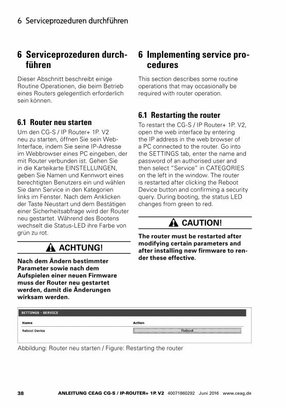
6.1 Restarting the routerTo restart the CG-S / IP Router+ 1P. V2, open the web interface by entering the IP address in the web browser of a PC connected to the router. Go into the SETTINGS tab, enter the name and password of an authorised user and then select “Service” in CATEGORIES on the left in the window. The router is restarted after clicking the Reboot Device button and confirming a security query. During booting, the status LED changes from green to red.
CAUTION!
The router must be restarted after modifying certain parameters and after installing new firmware to ren-der these effective.
6 Serviceprozeduren durch-führen
Dieser Abschnitt beschreibt einige Routine Operationen, die beim Betrieb eines Routers gelegentlich erforderlich sein können.
6.1 Router neu startenUm den CG-S / IP Router+ 1P. V2 neu zu starten, öffnen Sie sein Web-Interface, indem Sie seine IP-Adresse im Webbrowser eines PC eingeben, der mit Router verbunden ist. Gehen Sie in die Karteikarte EINSTELLUNGEN, geben Sie Namen und Kennwort eines berechtigten Benutzers ein und wählen Sie dann Service in den Kategorien links im Fenster. Nach dem Anklicken der Taste Neustart und dem Bestätigen einer Sicherheitsabfrage wird der Router neu gestartet. Während des Bootens wechselt die Status-LED ihre Farbe von grün zu rot.
ACHTUNG!
Nach dem Ändern bestimmter Parameter sowie nach dem Aufspielen einer neuen Firmware muss der Router neu gestartet werden, damit die Änderungen wirksam werden.
Abbildung: Router neu starten / Figure: Restarting the router
39
6 Implementing service procedures
MANUAL CEAG CG-S / IP-RoUTER+ 1P. V2 40071860292 June 2016 www.ceag.de
6.2 Konfiguration sichern und laden
Die aktuellen Einstellungen des Routers lassen sich als .rcf-Datei lokal abspei-chern und später erneut in das Gerät hochladen. Diese Datei beinhaltet die Router spezifischen Konfigurationsdaten in einem XML Format.
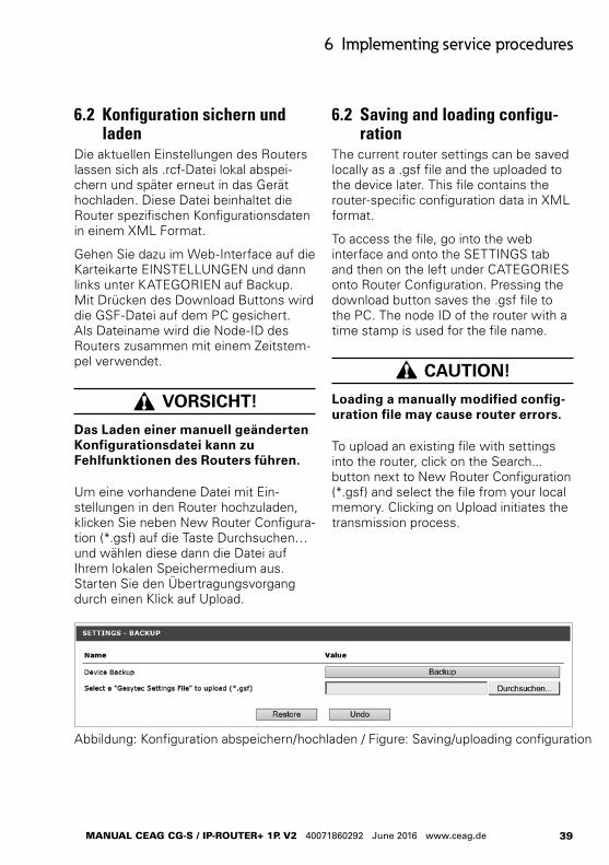
Gehen Sie dazu im Web-Interface auf die Karteikarte EINSTELLUNGEN und dann links unter KATEGORIEN auf Backup. Mit Drücken des Download Buttons wird die GSF-Datei auf dem PC gesichert. Als Dateiname wird die Node-ID des Routers zusammen mit einem Zeitstem-pel verwendet.
VORSICHT!
Das Laden einer manuell geänderten Konfigurations datei kann zu Fehlfunktionen des Routers führen.
Um eine vorhandene Datei mit Ein-stellungen in den Router hochzuladen, klicken Sie neben New Router Configura-tion (*.gsf) auf die Taste Durchsuchen… und wählen diese dann die Datei auf Ihrem lokalen Speichermedium aus. Starten Sie den Übertragungsvorgang durch einen Klick auf Upload.
6.2 Saving and loading configu-ration
The current router settings can be saved locally as a .gsf file and the uploaded to the device later. This file contains the router-specific configuration data in XML format.
To access the file, go into the web interface and onto the SETTINGS tab and then on the left under CATEGORIES onto Router Configuration. Pressing the download button saves the .gsf file to the PC. The node ID of the router with a time stamp is used for the file name.
CAUTION!
Loading a manually modified config-uration file may cause router errors.
To upload an existing file with settings into the router, click on the Search... button next to New Router Configuration (*.gsf) and select the file from your local memory. Clicking on Upload initiates the transmission process.
Abbildung: Konfiguration abspeichern/hochladen / Figure: Saving/uploading configuration
40
6 Serviceprozeduren durchführen
ANLEITUNG CEAG CG-S / IP-RoUTER+ 1P. V2 40071860292 Juni 2016 www.ceag.de
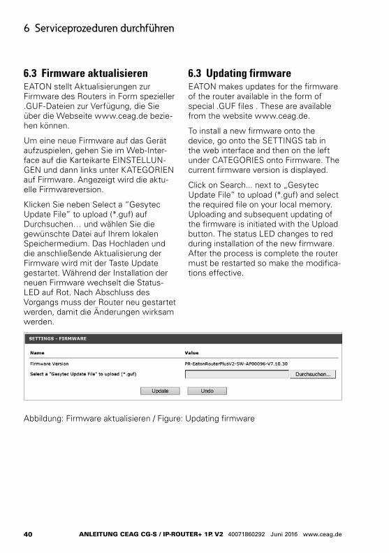
6.3 Firmware aktualisierenEATON stellt Aktualisierungen zur Firmware des Routers in Form spezieller .GUF-Dateien zur Verfügung, die Sie über die Webseite www.ceag.de bezie-hen können.
Um eine neue Firmware auf das Gerät aufzuspielen, gehen Sie im Web-Inter-face auf die Karteikarte EINSTELLUN-GEN und dann links unter KATEGORIEN auf Firmware. Angezeigt wird die aktu-elle Firmwareversion.
Klicken Sie neben Select a “Gesytec Update File” to upload (*.guf) auf Durchsuchen… und wählen Sie die gewünschte Datei auf Ihrem lokalen Speichermedium. Das Hochladen und die anschließende Aktualisierung der Firmware wird mit der Taste Update gestartet. Während der Installation der neuen Firmware wechselt die Status-LED auf Rot. Nach Abschluss des Vorgangs muss der Router neu gestartet werden, damit die Änderungen wirksam werden.
6.3 Updating firmwareEATON makes updates for the firmware of the router available in the form of special .GUF files . These are available from the website www.ceag.de.
To install a new firmware onto the device, go onto the SETTINGS tab in the web interface and then on the left under CATEGORIES onto Firmware. The current firmware version is displayed.
Click on Search... next to „Gesytec Update File“ to upload (*.guf) and select the required file on your local memory. Uploading and subsequent updating of the firmware is initiated with the Upload button. The status LED changes to red during installation of the new firmware. After the process is complete the router must be restarted so make the modifica-tions effective.
Abbildung: Firmware aktualisieren / Figure: Updating firmware
41
6 Implementing service procedures
MANUAL CEAG CG-S / IP-RoUTER+ 1P. V2 40071860292 June 2016 www.ceag.de
6.4 Resetting router to factory settings
Implement the following process to reset the CG-S / IP Router+ 1P. V2 to its factory settings:
1. Disconnect the power supply plug and wait half a minute.
2. Reconnect the power supply and immediately press the Factory Reset button on the top of the housing until the Start/Reset LED begins to flash (duration approx. 10 seconds).
3. Release the Factory Reset button and press it again for one second. The LED flashes quicker, and then quicker again. Then it lights up continuously. The resetting process has started.
4. After around one minute the LED Start/Reset extinguishes for the first time, followed by a short flash. It then lights up continuously for approx. one minute. When it goes off for a second time the device is restarted and resetting to factory settings is complete.
The router settings have now been reset to factory specifications.
CAUTION!
With resetting to factory set-tings the IP address is modified back to 192.168.1.250. Chapter 3.3 „Verbindung zum Web-Interface her-stellen“ informs about how to con-nect to the device. Any users created are also deleted and the „Admin“ default user is created again.
6.4 Router auf Werksein-stellungen zurücksetzen
Verfahren Sie nach folgender Prozedur, um den CG-S / IP Router+ 1P. V2 auf seine Werkseinstellungen zurückzusetzen:
1. Ziehen Sie den Stecker zur Span-nungsversorgung, warten Sie eine halbe Minute.
2. Schließen Sie die Spannungsver-sorgung wieder an und drücken Sie unmittelbar den Factory Reset Taster auf der Gehäuseoberseite bis die Start/Reset LED zu blinken beginnt (dauert ca. 10 Sekunden).
3. Lassen Sie den Taster Factory Reset los und drücken Sie ihn wieder für eine Sekunde. Die LED blinkt schneller, danach noch schneller. Schließlich bleibt sie an. Der Prozess des Rücksetzens hat begonnen.
4. Nach etwa einer Minute geht die LED Start/Reset zum ersten Mal aus, gefolgt von einem kurzen Aufblitzen. Sie geht dann wieder für etwa eine Minute an. Wenn sie zum zweiten Mal ausgeht, wird das Gerät neu gestartet und das Rücksetzen auf die Werksein-stellungen ist abgeschlossen.
Die Einstellungen des Routers sind jetzt auf die Werksvorgaben zurückgesetzt.
ACHTUNG!
Beim Rücksetzen auf die Werksein-stellungen wird die IP-Adresse wieder auf 192.168.1.250 geändert. Kapitel 3.3 „Verbindung zum Web-Interface herstel-len“ gibt Hinweise, wie die Verbindung zum Gerät hergestellt werden kann. Außerdem werden angelegte Benutzer entfernt und der Default Benutzer „Admin“ wieder angelegt.
42
7 Probleme lösen
ANLEITUNG CEAG CG-S / IP-RoUTER+ 1P. V2 40071860292 Juni 2016 www.ceag.de
7 TroubleshootingThis section covers typical problem situ-ations and aids their solving.
7.1 The web interface of the router cannot be opened
Symptoms
The browser registers a timeout when the page is opened.
Possible causes
• The device is not switched on• There is no ethernet connection• Problems with the IP addresses
Possible solutions
1. Check whether the router is connected to the power supply and whether this is functional.
2. Does the Status LED light up green? If the Status LED does not light up green at the most within three minutes after switching on, please contact the service team from EATON.
3. Does the Status LED flash red or red/green? In this case the router has problems with the IP address. There is either an IP address conflict with another device in the IP network, or if DHCP is activated the router has not been assigned an IP address. Ask the network administrator for valid addresses.
7 Probleme lösenDieser Abschnitt befasst sich mit typi-schen Problemsituationen und gibt Hilfe zu deren Behebung.
7.1 Das Web-Interface des Routers kann nicht geöffnet werden
Symptome
Der Browser meldet beim Öffnen der Seite einen Timeout.
Mögliche Ursachen
• Das Gerät ist nicht eingeschaltet• Es besteht keine Ethernet Verbindung• Probleme mit den IP-Adressen
Lösungsvorschläge
1. Überprüfen Sie, ob der Router mit der Spannungsversorgung verbunden ist, und ob diese funktioniert.
2. Leuchtet die Status LED grün? Sollte die Status LED spätestens drei Minuten nach dem Einschalten nicht grün leuchten, so nehmen Sie bitte Kontakt mit dem Service der Firma EATON auf.
3. Blinkt die Status LED rot oder rot/grün? In diesem Fall hat der Router Prob-leme mit der IP-Adresse. Es kann entweder ein IP-Adress-Konflikt mit einem anderen Gerät im IP Netzwerk bestehen oder, falls DHCP aktiviert ist, hat der Router keine IP-Adresse zugewiesen bekommen. Fragen Sie den Netzwerk Administrator nach gültigen Adressen.
43
7 Troubleshooting
MANUAL CEAG CG-S / IP-RoUTER+ 1P. V2 40071860292 June 2016 www.ceag.de
4. Prüfen Sie die Leuchtdioden an der Ethernet Buchse des CG-S / IP Router+ 1P. V2. Die grüne LED muss l euchten. Die gelbe LED gibt an, ob 10 MBit/s oder 100 MBit/s als Geschwindigkeit erkannt wurde.
Prüfen Sie ebenfalls am PC, ob einer Ethernet Verbindung besteht.
5. Prüfen Sie mit den DeviceFinder, ob der CG-S / IP Router+ 1P. V2 gefun-den wird und zwar mit der korrekten IP-Adresse. Bei der Verwendung von DHCP im Router oder am PC kann es vorkom-men, dass sich die Geräte nicht im gleichen Subnet befinden und daher keine Verbindung aufgebaut werden kann. Konfigurieren Sie die IP Einstellungen des PC so, dass eine Kommunikation mit dem CG-S / IP Router+ 1P. V2 möglich ist.
6. Sie sind dabei, mehrere Geräte nacheinander zu konfigurieren und stellen die Standard IP-Adresse 192.168.1.250 des CG-S / IP Router+ 1P. V2 auf die in der Installation gewünschte Adresse um? In diesem Fall kann es sein, dass sich der PC noch die MAC-Adresse des vorherigen Gerätes zusammen mit der IP-Adresse 192.168.1.250 gemerkt hat. Ein neues Gerät kann dann unter 192.168.1.250 nicht ange-sprochen werden, da der PC dies unter der alten MAC-Adresse erwar-tet. Geben Sie in der Kommandozeile den Befehl „arp -d“ ein. Damit löscht der PC die veraltete Zuordnung.
4. Check the LEDs on the ethernet socket of the CG-S / IP Router+ 1P. V2. The green LED must light up. The yellow LED specifies whether a speed of 10 MBit/s or 100 MBit/s has been detected.
Also check on the PC whether an ethernet connection exists.
5. Test with the DeviceFinder whether the CG-S / IP Router+ 1P. V2 has been located, and also with the correct IP address. With use of DHCP in the router or on the PC it may occur that the devic-es are not in the same subnet, and as a result no connection can be estab-lished. Configure the IP settings of the PC to enable communication with the CG-S / IP Router+ 1P. V2.
6. Do you want to configure several devices consecutively and modify the standard 192.168.1.250 address of the CG-S / IP Router+ 1P. V2 to the ad-dress required in the installation? In this case it may have occurred that the PC has noted the MAC address of the previous device together with the IP address 192.168.1.250. A new device can therefore not be responded to with 192.168.1.250 because the PC expects this under the old MAC address. Enter „arp -d“ into the command line. The PC then deletes the obsolete assignment.

Eatons Ziel ist es, zuverlässige, effiziente und sichere Stromversorgung dann zu bieten, wenn sie am meisten benötigt wird. Die Experten von Eaton verfügen über ein umfassendes Fachwissen im Bereich Energiemanagement in verschiedensten Branchen und sorgen so für kundens-pezifische, integrierte Lösungen, um anspruchsvollste Anforderungen der Kunden zu erfüllen.
Wir sind darauf fokussiert, stets die richtige Lösung für jede Anwendung zu finden. Dabei erwarten Entscheidungsträger mehr als lediglich innovative Produkte. Unternehmen wen-den sich an Eaton, weil individuelle Unterstützung und der Erfolg unserer Kunden stets an erster Stelle stehen. Für mehr Informationen besuchen Sie www.eaton.de.
Ihre Ansprechpartner finden Sie unter www.ceag.de.
At Eaton, we’re energized by the challenge of powering a world that demands more. With over 100 years experience in electrical power management, we have the expertise to see beyond today. From groundbreaking products to turnkey design and engineering services, critical industries around the globe count on Eaton.
We power businesses with reliable, efficient and safe electrical power management solutions. Combined with our personal service, support and bold thinking, we are answering tomorrow’s needs today. Follow the charge with Eaton. Visit eaton.eu.
You will find your contact partner at www.ceag.de.
EatonEMEA HeadquartersRoute de la Longeraie 71110 Morges, SwitzerlandEaton.eu
CEAG Notlichtsysteme GmbHSenator-Schwartz-Ring 2659494 Soest, GermanyTel.: +49 (0) 2921 69-870Fax: +49 (0) 2921 69-617E-mail: [email protected] Web: www.ceag.de
© 2016 EatonAlle Rechte vorbehaltenPrinted in GermanyPublikations-Nr. MN451020MLBestell-Nr. 40071860292Juni 2016