Embed Size (px)
Citation preview
Products Solutions ServicesXA00252P-C/00/A3/15.1671314067
Safety InstructionsCerabar SPMP71, PMP754-20 mA HART, PROFIBUS PA,
FOUNDATION Fieldbus
II 1/2 G Ex ia IIC T6/T4 Ga/GbII 2 G Ex d IIC T6/T4 GbKEMA 05 ATEX 1009
0 DE Dokument: XA00252P-CSicherheitshinweise für elektrische Betriebsmittel für explosionsgefährdete Bereiche → 5
EN Document: XA00252P-CSafety instructions for electrical apparatus for explosion-hazardous areas → 11
FR Document : XA00252P-CConseils de sécurité pour matériels électriques destinés aux zones explosibles → 17

XA00252P-C Cerabar S
2
BG - .
, .
Endress+Hauser
CE, .
, .
CS - Bezpe nostní pokyny pro elektrické p ístroje v místech s nebezpe ímvýbuchu. Pokud nemáte mo�nost p e íst si tento návod, m �ete si u násobjednat návod p elo�ený do svého jazyka. EU prohlá�ení o shodSpole nost Endress+Hauser prohla�uje prost ednictvím tohoto prohlá�ení a pou�itím zna ky CE, �e tento výrobek vyhovuje p íslu�ným evropským sm rnicím. Zmín né sm rnice, normy a dokumenty jsou uvedeny v Prohlá�ení o shod .
DA - Sikkerhedsforskrifter for elektriske apparater certificeret til brug ieksplosionsfarlige områder. Hvis du ikke forstår denne manual, kan en oversat kopi af den på dit eget sprog bestilles fra os.EU-overensstemmelseserklæringMed denne overensstemmelseserklæring og tilføjelsen af CE-mærketsikrer producenten Endress+Hauser, at produktet er i overensstemmelse med relevante europæiske direktiver. Dokumentation for overensstemmelsen gives i de anførte direktiver, standarder og dokumenter.
EL - .
, .
CE Endress+Hauser , .
, .
ES - Instrucciones de seguridad de aparatos eléctricos homologados para suutilización en áreas expuestas a riesgos de deflagración. Si no entiendeeste manual, puede pedir un ejemplar en su idioma.Declaración UE de conformidadPor la presente declaración y la inclusión de la marca CE, el fabricante Endress+Hauser, declara que el producto cumple con las directivas europeas pertinentes. Las directivas, normas y documentos de aplicación se indican en la declaración de conformidad.
ET - Ohutusjuhised plahvatusohtlikus keskkonnas kasutatavate elektriseadmete kohta. Kui Te ei saa käesolevast juhendist aru, võite meilt tellida Teie riigikeelde tõlgitud juhendi.ELi vastavusdeklaratsioonTootja Endress+Hauser kinnitab juurdelisatud vastavusdeklaratsiooni esitamisega ja CE-märgise kandmisega tootele, et käesolev toode vastab kohaldatavate Euroopa Liidu direktiivide nõuetele. Kohaldatavad direktiivid, standardid ja dokumendid on ära toodud vastavusdeklaratsioonis.
FI - Turvallisuusohjeita sähkölaitteille, jotka on vahvistettu käytettäväksiräjähdysvaarallisilla alueilla. Jos et ymmärrä tätä käsikirjaa, voit tilatameiltä käännöksen omalla kansallisella kielelläsi.EU-vaatimustenmukaisuusvakuutusValmistaja Endress+Hauser vakuuttaa tällä vaatimustenmukaisuustodistuksella ja CE-merkin kiinnittämisellä, ettätämä tuote täyttää sovellettavien EU-direktiivien määräykset. Sovellettavat direktiivit, normit ja dokumentit on merkitty vaatimustenmukaisuustodistukseen.
HR - Sigurnosni naputci za elektromaterijal u sredini u kojoj prijeti opasnost odeksplozije. Ako Vam nije mogu e itati ovaj naputak, onda imate mogu nostda kod nas naru ite naputak sastavljen na Va�em materinskom jeziku.EU izjava o sukladnostiDobavlja Endress+Hauser jam i ovom izjavom i stavljanjem oznake CE daovaj proizvod udovoljava zahtjevima europskih direktiva koje su na snazi. U izjavi o usugla�enosti se navode direktive, norme i dokumenti koji su nasnazi.
HU - Biztonsági információk robbanásveszélyes területre való elektromoseszközökhöz. Amennyiben nem tudja elolvasni ezt az útmutatót, akkormegrendelheti az Ön anyanyelvére lefordítva is.EU-megfelel ségi nyilatkozatAz Endress+Hauser mint gyártó jelen megfelel ségi nyilatkozattal és a CE-jelzés felhelyezésével kijelenti, hogy ez a termék megfelel az alkalmazandó európai irányelveknek. Az alkalmazott irányelvek, szabványok és dokumentumok a megfelel ségi nyilatkozatban fel vannak tüntetve.
IT - Istruzioni di sicurezza per apparecchiature elettriche certificate per l'utilizzo in aree con pericolo di esplosione. Se il presente manuale non risulta comprensibile potete ordinarcene una copia tradotta nella vostra lingua.Dichiarazione di conformità UECon questa dichiarazione e con l'applicazione del marchio CE, il costruttore Endress+Hauser, assicura che il prodotto è conforme alle direttive europee vigenti. Prova della conformità è fornita dall'osservanza delle direttive, delle norme e dei documenti elencati.
LT - Elektros renginio saugumo nurodymai, susij su sprogimo zonomis. Jeigu negalite perskaityti �ios instrukcijos, kreipkit s mus, kad u�sisakytum te j s gimt j kalb i�verst instrukcij .ES atitikties deklaracijaGamintojas Endress+Hauser �ia atitikties deklaracija ir CE �enklinimu patvirtina, kad gaminys atitinka taikytinas ES direktyvas. Taikomos direktyvos, normos ir dokumentai yra pateikiami atitikties deklaracijoje.
LV - Dro� bas nor d jumi elektrisko darba instrumentu lieto�anai apgabalos, kas pak auti spr dzienb stam bai. Ja Jums nav iesp ju izlas t �os nor d jumus, J s varat pas t t pie mums tulkojumu J su valsts valod .ES atbilst bas deklar cijaRa�ot js Endress+Hauser ar �o atbilst bas apliecin jumu un CE z mola lietojumu apstiprina, ka produkts izgatavots saka ar atbilsto�aj m Eiropas vadl nij m. Piem rot s vadl nijas, normas un dokumenti atrun ti atbilst bas apliecin jum .
NL - Veiligheidsinstructies voor elektrisch materieel in explosiegevaarlijkeomgeving. Wanneer u deze handleiding niet kunt lezen, kunt u een inuw landstaal vertaalde handleiding bij ons bestellen.EU-conformiteitsverklaringDe leverancier Endress+Hauser waarborgt met deze verklaring en het aanbrengen van het CE-teken, dat dit product overeenstemt met de geldende Europese richtlijnen. De geldende richtlijnen, normen en documenten zijn aangegeven in de conformiteitsverklaring.
PL - Wskazówki dot. bezpiecze stwa dla urz dze elektrycznych stosowanych w obszarze zagro onym wybuchem. Je li niniejsza instrukcja napisana jest w j zyku, którym si nie pos ugujesz, mo esz zamówi u nas przet umaczony dokument.Deklaracja zgodno ci UEProducent Endress+Hauser w niniejszej deklaracji zgodno ci wraz z nadaniem znaku CE o wiadcza, e produkt ten jest zgodny z obowi zuj c Europejsk Dyrektyw . Zastosowane wytyczne, normy oraz dukumenty podane s w deklaracji zgodno ci.
PT - Instruções de segurança para dispositivos eléctricos certificados parautilização em áreas de risco de incêndio. Se não compreender estemanual, pode encomendar-nos directamente uma cópia na sua língua.Declaração UE de conformidadeCom esta declaração de conformidade e a aplicação da marca CE, o fabricante Endress+Hauser, garante que o produto obedece às directivas europeias a aplicar. As directivas, normas e documentos são apresentadas na declaração de conformidade.
RO - Indica ii de siguran pentru mijloacele de produc ie electrice pentru zonele periclitate de explozie. Dac nu pute i citi aceste instruc iuni, atunci pute i comanda la noi instruc iunile traduse în limba rii dumneavoastr .Declara ia UE de conformitateProduc torul Endress+Hauser declar prin declara ia de conformitate al turat i prin aplicarea semnului CE c acest produs corespunde directivelor europene aplicabile. Directivele, normele aplicate i documentele sunt men ionate în declara ia de conformitate.
SK - Bezpe nostné pokyny pre elektrické zariadenie prevádzkované v priestoroch s nebezpe enstvom výbuchu. Ak nemáte mo�nost� pre ítat� si tento návod, mô�ete si u nás objednat� návod prelo�ený do svojho jazyka.EÚ vyhlásenie o zhodeSpolo nos Endress+Hauser vyhlasuje prostredníctvom tohto vyhlásenia o konformite a pou�itím zna ky CE, �e tento výrobok vyhovuje príslu�ným európskym smerniciam. Zmie ované smernice, normy a dokumenty sú uvedené vo Vyhlásení o konformite.
SL - Varnostni napotki glede elektri ne opreme, namenjene za uporabo veksplozivnih obmo jih. e teh navodil ne morete razumeti, lahko pri nasnaro ite prevod v va� jezik.Izjava EU o skladnostiProizvajalec Endress+Hauser s to izjavo o skladnosti in navedbo oznake CE izjavlja, da je ta izdelek skladen s predpisanimi evropskimi smernicami. Upo�tevane smernice, standardi in dokumenti so navedeni v izjavi o skladnosti.
SV - Säkerhetsföreskrifter för elektrisk utrustning certifierad för användning i explosionsfarliga områden. Om du inte förstår denna manual, kan en översatt kopia på ditt eget språk beställas från oss.EU-försäkran om överensstämmelseEndress+Hauser försäkrar med vidstående försäkran om överensstämmelse och med CE-märkningen att denna produkt överensstämmer med de tillämpbara europeiska riktlinjerna. De tillämpade riktlinjerna, normerna och dokumenten anges i försäkran om överensstämmelse.

Cerabar S XA00252P-C
3
Konfo

XA00252P-C Cerabar S
4

Cerabar S XA00252P-C
5
Cerabar SPMP71, PMP75
4-20 mA HART, PROFIBUS PA, FOUNDATION Fieldbus
Kombizulassung, allgemeine Hinweise
Dieses Gerät ist für die Installation in der Zündschutzart "Eigensicherheit Ex i" oder "Druckfeste Kapselung Ex d" geeignet.
• Die verwendete Zündschutzart muss vor der ersten Inbetriebnahme festgelegt werden.• Eine Änderung der verwendeten Zündschutzart nach der ersten Inbetriebnahme kann den
Explosionsschutz gefährden und ist nicht zulässig!
" Achtung!Abhängig von der verwendeten Zündschutzart sind die folgenden Sicherheitshinweise für die Installation in Zündschutzart "Eigensicherheit" (Teil 1) oder "Druckfeste Kapselung" (Teil 2) zu beachten.
Zugehörige Dokumentation Dieses Dokument ist fester Bestandteil der folgenden Betriebsanleitungen:HART: BA00271P/00, BA00274P/00 PROFIBUS PA: BA00295P/00, BA00296P/00 FOUNDATION Fieldbus: BA00302P/00, BA00303P/00
Es gilt die mitgelieferte, dem Gerätetyp entsprechende Betriebsanleitung.
Ergänzende Dokumentation Explosionsschutz-Broschüre:CP00021Z/11
deuts
ch
XA00252P-C Cerabar S
6
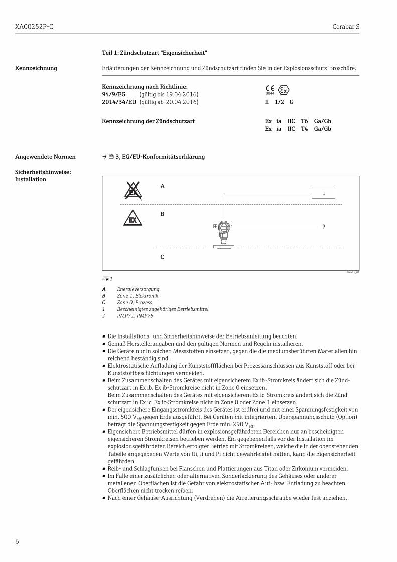
Teil 1: Zündschutzart "Eigensicherheit"
Kennzeichnung Erläuterungen der Kennzeichnung und Zündschutzart finden Sie in der Explosionsschutz-Broschüre.
Angewendete Normen → 3, EG/EU-Konformitätserklärung
Sicherheitshinweise:Installation
PMx7x_01
å 1
A EnergieversorgungB Zone 1, ElektronikC Zone 0, Prozess1 Bescheinigtes zugehöriges Betriebsmittel2 PMP71, PMP75
• Die Installations- und Sicherheitshinweise der Betriebsanleitung beachten.• Gemäß Herstellerangaben und den gültigen Normen und Regeln installieren.• Die Geräte nur in solchen Messstoffen einsetzen, gegen die die mediumsberührten Materialien hin-
reichend beständig sind.• Elektrostatische Aufladung der Kunststoffflächen bei Prozessanschlüssen aus Kunststoff oder bei
Kunststoffbeschichtungen vermeiden.• Beim Zusammenschalten des Gerätes mit eigensicherem Ex ib-Stromkreis ändert sich die Zünd-
schutzart in Ex ib. Ex ib-Stromkreise nicht in Zone 0 einsetzen.Beim Zusammenschalten des Gerätes mit eigensicherem Ex ic-Stromkreis ändert sich die Zünd-schutzart in Ex ic. Ex ic-Stromkreise nicht in Zone 0 oder Zone 1 einsetzen.
• Der eigensichere Eingangsstromkreis des Gerätes ist erdfrei und mit einer Spannungsfestigkeit von min. 500 Veff gegen Erde ausgeführt. Bei Geräten mit integriertem Überspannungsschutz (Option) beträgt die Spannungsfestigkeit gegen Erde min. 290 Veff.
• Eigensichere Betriebsmittel dürfen in explosionsgefährdeten Bereichen nur an bescheinigten eigensicheren Stromkreisen betrieben werden. Ein gegebenenfalls vor der Installation im explosionsgefährdeten Bereich erfolgter Betrieb mit Stromkreisen, welche die in der obenstehenden Tabelle angegebenen Werte von Ui, Ii und Pi nicht gewährleistet hatten, kann die Eigensicherheit gefährden.
• Reib- und Schlagfunken bei Flanschen und Plattierungen aus Titan oder Zirkonium vermeiden.• Im Falle einer zusätzlichen oder alternativen Sonderlackierung des Gehäuses oder anderer
metallenen Oberflächen ist die Gefahr von elektrostatischer Auf- bzw. Entladung zu beachten. Oberflächen nicht trocken reiben.
• Nach einer Gehäuse-Ausrichtung (Verdrehen) die Arretierungsschraube wieder fest anziehen.
Kennzeichnung nach Richtlinie:94/9/EG (gültig bis 19.04.2016)2014/34/EU (gültig ab 20.04.2016) II 1/2 G
Kennzeichnung der Zündschutzart Ex ia IIC T6 Ga/GbEx ia IIC T4 Ga/Gb
0044
B
A
1
2
C
Cerabar S XA00252P-C
7
Sicherheitshinweise:Zone 0
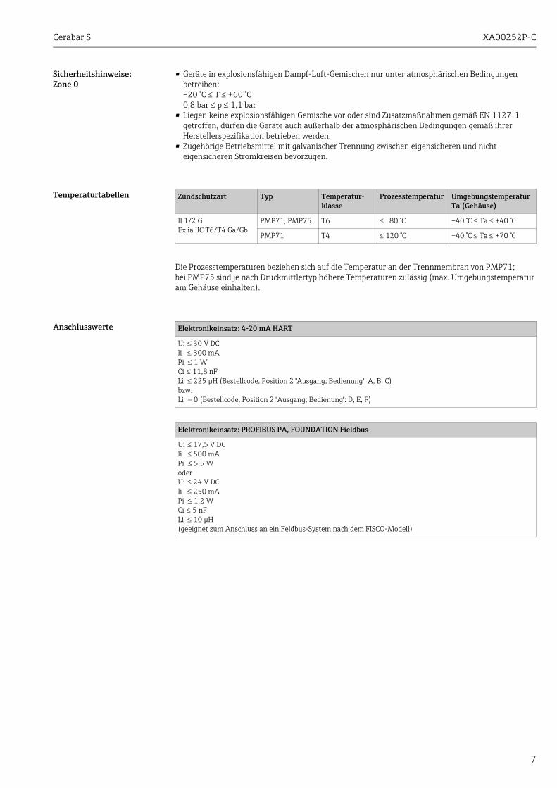
• Geräte in explosionsfähigen Dampf-Luft-Gemischen nur unter atmosphärischen Bedingungen betreiben:–20 °C T +60 °C0,8 bar p 1,1 bar
• Liegen keine explosionsfähigen Gemische vor oder sind Zusatzmaßnahmen gemäß EN 1127-1 getroffen, dürfen die Geräte auch außerhalb der atmosphärischen Bedingungen gemäß ihrer Herstellerspezifikation betrieben werden.
• Zugehörige Betriebsmittel mit galvanischer Trennung zwischen eigensicheren und nicht eigensicheren Stromkreisen bevorzugen.
Temperaturtabellen
Die Prozesstemperaturen beziehen sich auf die Temperatur an der Trennmembran von PMP71; bei PMP75 sind je nach Druckmittlertyp höhere Temperaturen zulässig (max. Umgebungstemperatur am Gehäuse einhalten).
Anschlusswerte
Zündschutzart Typ Temperatur-klasse
Prozesstemperatur Umgebungstemperatur Ta (Gehäuse)
II 1/2 GEx ia IIC T6/T4 Ga/Gb
PMP71, PMP75 T6 80 °C –40 °C Ta +40 °C
PMP71 T4 120 °C –40 °C Ta +70 °C
Elektronikeinsatz: 4-20 mA HART
Ui 30 V DCli 300 mAPi 1 WCi 11,8 nFLi 225 μH (Bestellcode, Position 2 "Ausgang; Bedienung": A, B, C)bzw.Li = 0 (Bestellcode, Position 2 "Ausgang; Bedienung": D, E, F)
Elektronikeinsatz: PROFIBUS PA, FOUNDATION Fieldbus
Ui 17,5 V DCli 500 mAPi 5,5 WoderUi 24 V DCli 250 mAPi 1,2 WCi 5 nFLi 10 μH(geeignet zum Anschluss an ein Feldbus-System nach dem FISCO-Modell)
XA00252P-C Cerabar S
8
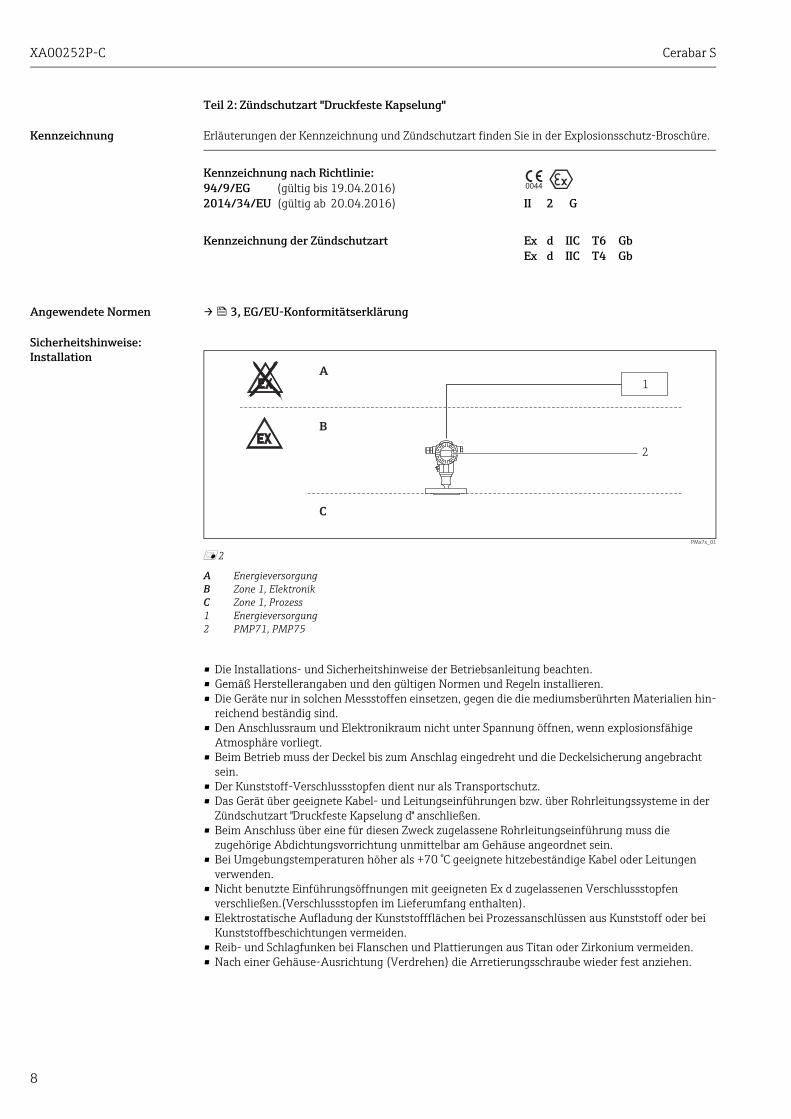
Teil 2: Zündschutzart "Druckfeste Kapselung"
Kennzeichnung Erläuterungen der Kennzeichnung und Zündschutzart finden Sie in der Explosionsschutz-Broschüre.
Angewendete Normen → 3, EG/EU-Konformitätserklärung
Sicherheitshinweise:Installation
PMx7x_01
å 2
A EnergieversorgungB Zone 1, ElektronikC Zone 1, Prozess1 Energieversorgung2 PMP71, PMP75
• Die Installations- und Sicherheitshinweise der Betriebsanleitung beachten.• Gemäß Herstellerangaben und den gültigen Normen und Regeln installieren.• Die Geräte nur in solchen Messstoffen einsetzen, gegen die die mediumsberührten Materialien hin-
reichend beständig sind.• Den Anschlussraum und Elektronikraum nicht unter Spannung öffnen, wenn explosionsfähige
Atmosphäre vorliegt.• Beim Betrieb muss der Deckel bis zum Anschlag eingedreht und die Deckelsicherung angebracht
sein.• Der Kunststoff-Verschlussstopfen dient nur als Transportschutz.• Das Gerät über geeignete Kabel- und Leitungseinführungen bzw. über Rohrleitungssysteme in der
Zündschutzart "Druckfeste Kapselung d" anschließen.• Beim Anschluss über eine für diesen Zweck zugelassene Rohrleitungseinführung muss die
zugehörige Abdichtungsvorrichtung unmittelbar am Gehäuse angeordnet sein.• Bei Umgebungstemperaturen höher als +70 °C geeignete hitzebeständige Kabel oder Leitungen
verwenden.• Nicht benutzte Einführungsöffnungen mit geeigneten Ex d zugelassenen Verschlussstopfen
verschließen.(Verschlussstopfen im Lieferumfang enthalten).• Elektrostatische Aufladung der Kunststoffflächen bei Prozessanschlüssen aus Kunststoff oder bei
Kunststoffbeschichtungen vermeiden.• Reib- und Schlagfunken bei Flanschen und Plattierungen aus Titan oder Zirkonium vermeiden.• Nach einer Gehäuse-Ausrichtung (Verdrehen) die Arretierungsschraube wieder fest anziehen.
Kennzeichnung nach Richtlinie:94/9/EG (gültig bis 19.04.2016)2014/34/EU (gültig ab 20.04.2016) II 2 G
Kennzeichnung der Zündschutzart Ex d IIC T6 GbEx d IIC T4 Gb
0044
B
A
1
2
C

Cerabar S XA00252P-C
9
Temperaturtabellen
Die Prozesstemperaturen beziehen sich auf die Temperatur an der Trennmembran von PMP71; bei PMP75 sind je nach Druckmittlertyp höhere Temperaturen zulässig (max. Umgebungstemperatur am Gehäuse einhalten).
Anschlusswerte
Zündschutzart Typ Temperatur-klasse
Prozesstemperatur Umgebungstemperatur Ta (Gehäuse)
II 2 GEx d IIC T6/T4 Gb
PMP71, PMP75 T6 80 °C –40 °C Ta +75 °C
PMP71 T4 120 °C –40 °C Ta +75 °C
Elektronikeinsatz: 4-20 mA HART
Ui 45 V DCP 3 W
Elektronikeinsatz: PROFIBUS PA, FOUNDATION Fieldbus
U 32 V DCP 3 W

XA00252P-C Cerabar S
10

Cerabar S XA00252P-C
11
Cerabar SPMP71, PMP75
4-20 mA HART, PROFIBUS PA, FOUNDATION Fieldbus
Combined approval,general notes
This device is suited for installation with explosion protection "intrinsic safety Ex i" or "flameproof enclosure Ex d".
• The type of protection used must be specified before initial commissioning.• Changing the type of protection used after initial commissioning can jeopardise the explosion
protection and is not permitted!
" Caution! Depending on the type of protection used, the following safety instructions should be observed for installation with explosion protection "intrinsic safety" (Part 1) or "flameproof enclosure" (Part 2).
Associated Documentation
This document is an integral part of the following Operating Instructions:HART: BA00271P/00, BA00274P/00 PROFIBUS PA: BA00295P/00, BA00296P/00 FOUNDATION Fieldbus: BA00302P/00, BA00303P/00
The Operating Instructions which are supplied and correspond to the device type apply.
Supplementary Documentation
Explosion-protection brochure:CP00021Z/11
engl
ish
XA00252P-C Cerabar S
12
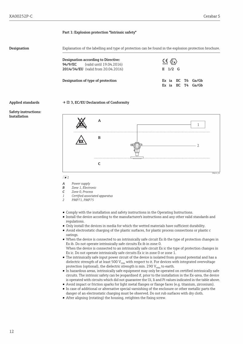
Part 1: Explosion protection "Intrinsic safety"
Designation Explanation of the labelling and type of protection can be found in the explosion protection brochure.
Applied standards → 3, EC/EU Declaration of Conformity
Safety instructions: Installation
PMx7x_01
å 1
A Power supplyB Zone 1, ElectronicC Zone 0, Process1 Certified associated apparatus2 PMP71, PMP75
• Comply with the installation and safety instructions in the Operating Instructions.• Install the device according to the manufacturer's instructions and any other valid standards and
regulations.• Only install the devices in media for which the wetted materials have sufficient durability.• Avoid electrostatic charging of the plastic surfaces, for plastic process connections or plastic c
oatings.• When the device is connected to an intrinsically safe circuit Ex ib the type of protection changes in
Ex ib. Do not operate intrinsically safe circuits Ex ib in zone 0.When the device is connected to an intrinsically safe circuit Ex ic the type of protection changes in Ex ic. Do not operate intrinsically safe circuits Ex ic in zone 0 or zone 1.
• The intrinsically safe input power circuit of the device is isolated from ground potential and has a dielectric strength of at least 500 Vrms with respect to it. For devices with integrated overvoltage protection (optional), the dielectric strength is min. 290 Vrms to earth.
• In hazardous areas, intrinsically safe equipment may only be operated on certified intrinsically safe circuits. The intrinsic safety can be jeopardised if, prior to the installation in the Ex-area, the device is operated with circuits which did not guarantee the Ui, Ii and Pi values indicated in the table above.
• Avoid impact or friction sparks for light metal flanges or flange faces (e.g. titanium, zirconium).• In case of additional or alternative special varnishing of the enclosure or other metallic parts the
danger of an electrostatic charging must be observed. Do not rub surfaces with dry cloth.• After aligning (rotating) the housing, retighten the fixing screw.
Designation according to Directive:94/9/EC (valid until 19.04.2016)2014/34/EU (valid from 20.04.2016) II 1/2 G
Designation of type of protection Ex ia IIC T6 Ga/GbEx ia IIC T4 Ga/Gb
0044
B
A
1
2
C
Cerabar S XA00252P-C
13
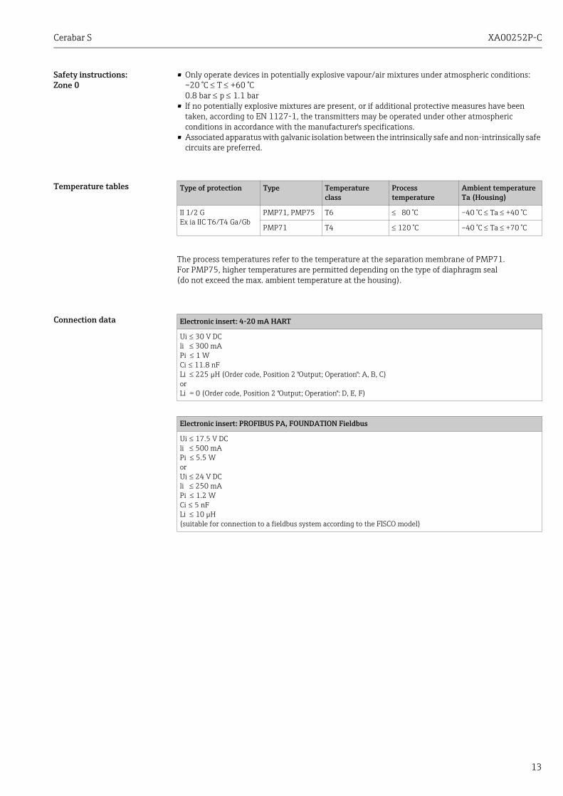
Safety instructions:Zone 0
• Only operate devices in potentially explosive vapour/air mixtures under atmospheric conditions:–20 °C T +60 °C0.8 bar p 1.1 bar
• If no potentially explosive mixtures are present, or if additional protective measures have been taken, according to EN 1127-1, the transmitters may be operated under other atmospheric conditions in accordance with the manufacturer's specifications.
• Associated apparatus with galvanic isolation between the intrinsically safe and non-intrinsically safe circuits are preferred.
Temperature tables
The process temperatures refer to the temperature at the separation membrane of PMP71. For PMP75, higher temperatures are permitted depending on the type of diaphragm seal (do not exceed the max. ambient temperature at the housing).
Connection data
Type of protection Type Temperature class
Process temperature
Ambient temperature Ta (Housing)
II 1/2 GEx ia IIC T6/T4 Ga/Gb
PMP71, PMP75 T6 80 °C –40 °C Ta +40 °C
PMP71 T4 120 °C –40 °C Ta +70 °C
Electronic insert: 4-20 mA HART
Ui 30 V DCli 300 mAPi 1 WCi 11.8 nFLi 225 μH (Order code, Position 2 "Output; Operation": A, B, C)orLi = 0 (Order code, Position 2 "Output; Operation": D, E, F)
Electronic insert: PROFIBUS PA, FOUNDATION Fieldbus
Ui 17.5 V DCli 500 mAPi 5.5 WorUi 24 V DCli 250 mAPi 1.2 WCi 5 nFLi 10 μH(suitable for connection to a fieldbus system according to the FISCO model)
XA00252P-C Cerabar S
14
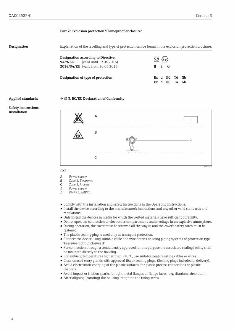
Part 2: Explosion protection "Flameproof enclosure"
Designation Explanation of the labelling and type of protection can be found in the explosion protection brochure.
Applied standards → 3, EC/EU Declaration of Conformity
Safety instructions: Installation
PMx7x_01
å 2
A Power supplyB Zone 1, ElectronicC Zone 1, Process1 Power supply2 PMP71, PMP75
• Comply with the installation and safety instructions in the Operating Instructions.• Install the device according to the manufacturer's instructions and any other valid standards and
regulations.• Only install the devices in media for which the wetted materials have sufficient durability.• Do not open the connection or electronics compartments under voltage in an explosive atmosphere.• During operation, the cover must be screwed all the way in and the cover's safety catch must be
fastened.• The plastic sealing plug is used only as transport protection.• Connect the device using suitable cable and wire entries or using piping systems of protection type
"Pressure-tight Enclosure d".• For connection through a conduit entry approved for this purpose the associated sealing facility shall
be mounted directly to the housing.• For ambient temperatures higher than +70 °C, use suitable heat-resisting cables or wires.• Close unused entry glands with approved (Ex d) sealing plugs. (Sealing plugs included in delivery).• Avoid electrostatic charging of the plastic surfaces, for plastic process connections or plastic
coatings.• Avoid impact or friction sparks for light metal flanges or flange faces (e.g. titanium, zirconium).• After aligning (rotating) the housing, retighten the fixing screw.
Designation according to Directive:94/9/EC (valid until 19.04.2016)2014/34/EU (valid from 20.04.2016) II 2 G
Designation of type of protection Ex d IIC T6 GbEx d IIC T4 Gb
0044
B
A
1
2
C

Cerabar S XA00252P-C
15
Temperature tables
The process temperatures refer to the temperature at the separation membrane of PMP71. For PMP75, higher temperatures are permitted depending on the type of diaphragm seal (do not exceed the max. ambient temperature at the housing).
Connection data
Type of protection Type Temperature class
Process temperature
Ambient temperature Ta (Housing)
II 2 GEx d IIC T6/T4 Gb
PMP71, PMP75 T6 80 °C –40 °C Ta +75 °C
PMP71 T4 120 °C –40 °C Ta +75 °C
Electronic insert: 4-20 mA HART
U 45 V DCP 3 W
Electronic insert: PROFIBUS PA, FOUNDATION Fieldbus
U 32 V DCP 3 W

XA00252P-C Cerabar S
16

Cerabar S XA00252P-C
17
Cerabar SPMP71, PMP75
4-20 mA HART, PROFIBUS PA, FOUNDATION Fieldbus
Agrément combiné,généralités
Le présent appareil est approprié pour une installation en mode de protection "Sécurité intrinsèque Ex i " ou "Enveloppe anti-déflagrante Ex d".
• Le mode de protection utilisé doit être déterminé avant la première mise en service.• Une modification du mode de protection après la première mise en service peut compromettre la
protection contre les risques d'explosion et n'est pas permise!
" Attention ! En fonction du mode de protection utilisé il convient de tenir compte des conseils de sécurité suivants pour l'installation en mode de protection "Sécurité intrinsèque" (partie 1) ou "Enveloppe anti-déflagrante" (partie 2).
Documentation correspondante
Le présent document fait partie intégrante du manuel de mise en service suivant :HART : BA00271P/00, BA00274P/00 PROFIBUS PA : BA00295P/00, BA00296P/00 FOUNDATION Fieldbus : BA00302P/00, BA00303P/00
C'est le manuel de mise en service fourni, correspondant au type d'appareil, qui est valable.
Documentation complémentaire
Brochure sur la protection contre les explosions :CP00021Z/11
fran
isça
XA00252P-C Cerabar S
18
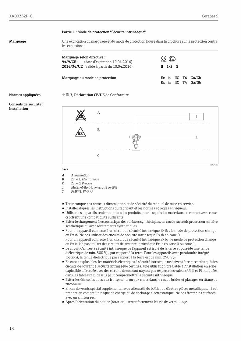
Partie 1 : Mode de protection "Sécurité intrinsèque"
Marquage Une explication du marquage et du mode de protection figure dans la brochure sur la protection contre les explosions.
Normes appliquées → 3, Déclaration CE/UE de Conformité
Conseils de sécurité : Installation
PMx7x_01
å 1
A AlimentationB Zone 1, ElectroniqueC Zone 0, Process1 Matériel électrique associé certifié2 PMP71, PMP75
• Tenir compte des conseils d'installation et de sécurité du manuel de mise en service.• Installer d'après les instructions du fabricant et les normes et règles en vigueur.• Utiliser les appareils seulement dans les produits pour lesquels les matériaux en contact avec ceux-
ci offrent une compatibilité suffisante.• Eviter le chargement électrostatique des surfaces synthétiques, en cas de raccords process en matière
synthétique ou avec revêtements synthétiques.• Pour un appareil connecté à un circuit de sécurité intrinsèque Ex ib , le mode de protection change
en Ex ib. Ne pas utiliser des circuits de sécurité intrinsèque Ex ib en zone 0.Pour un appareil connecté à un circuit de sécurité intrinsèque Ex ic , le mode de protection change en Ex ic. Ne pas utiliser des circuits de sécurité intrinsèque Ex ic en zone 0 ou zone 1.
• Le circuit d'entrée à sécurité intrinsèque de l'appareil est isolé de la terre et possède une tenue diélectrique de min. 500 Veff par rapport à la terre. Pour les appareils avec parafoudre intégré (option), la tenue diélectrique par rapport à la terre est de min. 290 Veff.
• En zones explosibles, les matériels électriques à sécurité intrisèque ne doivent être raccordés qu'à des circuits de courant à sécurité intrinsèque certifiés. Une utilisation préalable à l'installation en zone explosible effectuée avec des circuits de courant n'ayant pas respecté les valeurs Ui, Ii et Pi indiquées dans les tableaux ci-dessus peut compromettre la sécurité intrinsèque.
• Eviter les étincelles dues aux frottements ou aux chocs dans le cas de brides et placages en titane ou zirconium.
• En cas de vernis spécial supplémentaire ou alternatif du boîtier ou d'autres pièces métalliques, il faut prendre en compte un risque de charge ou de décharge électrostatique. Ne pas frotter les surfaces avec un chiffon sec.
• Après l'orientation du boîtier (rotation), serrer fortement les vis de verrouillage.
Marquage selon directive :94/9/CE (date d’expiration 19.04.2016)2014/34/UE (valide à partir du 20.04.2016) II 1/2 G
Marquage du mode de protection Ex ia IIC T6 Ga/GbEx ia IIC T4 Ga/Gb
0044
B
A
1
2
C
Cerabar S XA00252P-C
19
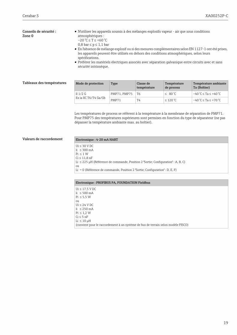
Conseils de sécurité :Zone 0
• N'utiliser les appareils soumis à des mélanges explosifs vapeur - air que sous conditions atmosphériques :–20 °C T +60 °C0,8 bar p 1,1 bar
• En l'absence de mélange explosif ou si des mesures complémentaires selon EN 1127-1 ont été prises, les appareils peuvent être utilisés en dehors des conditions atmosphériques, selon leurs spécifications.
• Préférer les matériels électriques associés avec séparation galvanique entre circuits avec et sans sécurité intrinsèque.
Tableaux des températures
Les températures de process se réfèrent à la température à la membrane de séparation de PMP71. Pour PMP75 des températures supérieures sont permises en fonction du type de séparateur (ne pas dépasser la température ambiante max. au boîtier).
Valeurs de raccordement
Mode de protection Type Classe de température
Températurede process
Température ambiante Ta (Boîtier)
II 1/2 GEx ia IIC T6/T4 Ga/Gb
PMP71, PMP75 T6 80 °C –40 °C Ta +40 °C
PMP71 T4 120 °C –40 °C Ta +70 °C
Electronique : 4-20 mA HART
Ui 30 V DCli 300 mAPi 1 WCi 11,8 nFLi 225 μH (Référence de commande, Position 2 "Sortie; Configuration" : A, B, C)ouLi = 0 (Référence de commande, Position 2 "Sortie; Configuration" : D, E, F)
Electronique : PROFIBUS PA, FOUNDATION Fieldbus
Ui 17,5 V DCli 500 mAPi 5,5 WouUi 24 V DCli 250 mAPi 1,2 WCi 5 nFLi 10 μH(convient pour le raccordement à un système de bus de terrain selon modèle FISCO)
XA00252P-C Cerabar S
20
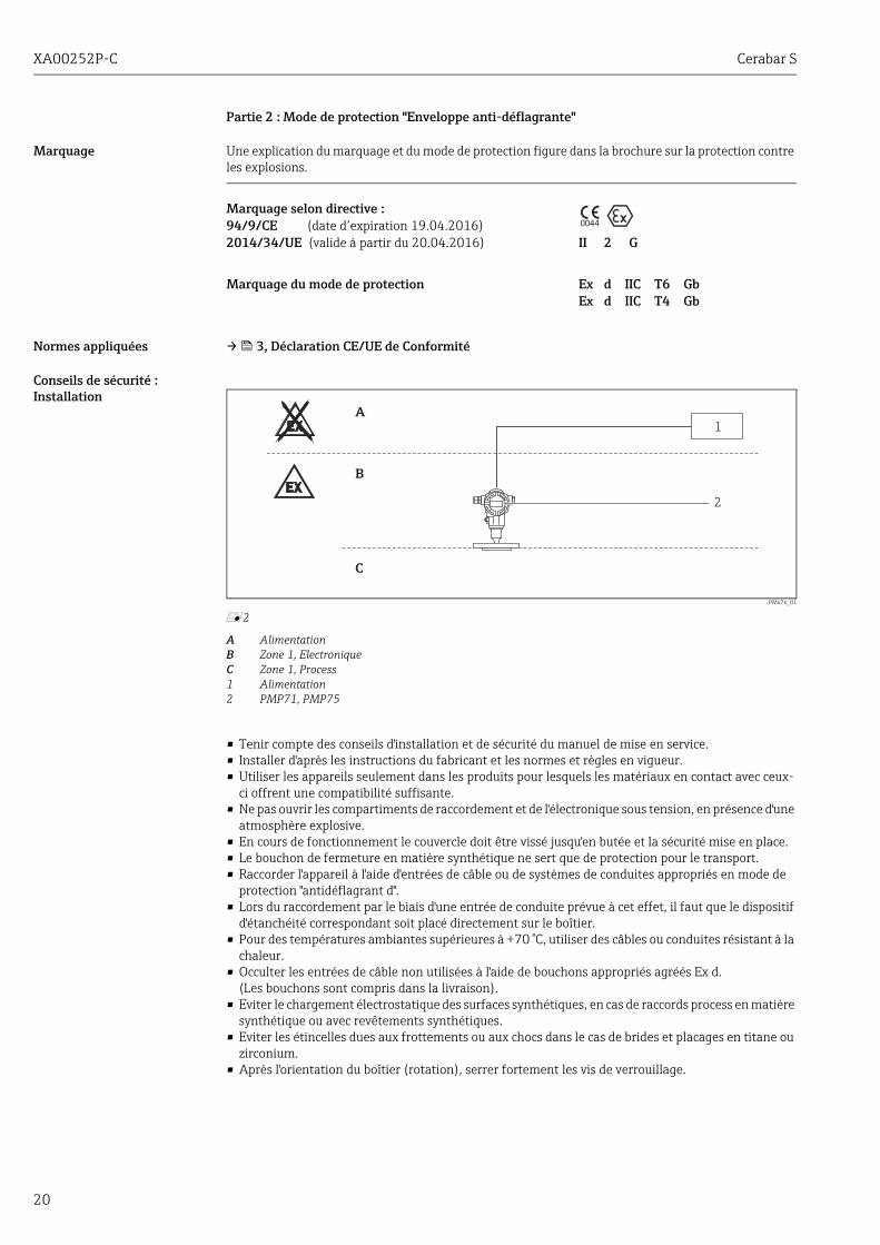
Partie 2 : Mode de protection "Enveloppe anti-déflagrante"
Marquage Une explication du marquage et du mode de protection figure dans la brochure sur la protection contre les explosions.
Normes appliquées → 3, Déclaration CE/UE de Conformité
Conseils de sécurité : Installation
PMx7x_01
å 2
A AlimentationB Zone 1, ElectroniqueC Zone 1, Process1 Alimentation2 PMP71, PMP75
• Tenir compte des conseils d'installation et de sécurité du manuel de mise en service.• Installer d'après les instructions du fabricant et les normes et règles en vigueur.• Utiliser les appareils seulement dans les produits pour lesquels les matériaux en contact avec ceux-
ci offrent une compatibilité suffisante.• Ne pas ouvrir les compartiments de raccordement et de l'électronique sous tension, en présence d'une
atmosphère explosive.• En cours de fonctionnement le couvercle doit être vissé jusqu'en butée et la sécurité mise en place.• Le bouchon de fermeture en matière synthétique ne sert que de protection pour le transport.• Raccorder l'appareil à l'aide d'entrées de câble ou de systèmes de conduites appropriés en mode de
protection "antidéflagrant d".• Lors du raccordement par le biais d'une entrée de conduite prévue à cet effet, il faut que le dispositif
d'étanchéité correspondant soit placé directement sur le boîtier.• Pour des températures ambiantes supérieures à +70 °C, utiliser des câbles ou conduites résistant à la
chaleur.• Occulter les entrées de câble non utilisées à l'aide de bouchons appropriés agréés Ex d.
(Les bouchons sont compris dans la livraison).• Eviter le chargement électrostatique des surfaces synthétiques, en cas de raccords process en matière
synthétique ou avec revêtements synthétiques.• Eviter les étincelles dues aux frottements ou aux chocs dans le cas de brides et placages en titane ou
zirconium.• Après l'orientation du boîtier (rotation), serrer fortement les vis de verrouillage.
Marquage selon directive :94/9/CE (date d’expiration 19.04.2016)2014/34/UE (valide à partir du 20.04.2016) II 2 G
Marquage du mode de protection Ex d IIC T6 GbEx d IIC T4 Gb
0044
B
A
1
2
C

Cerabar S XA00252P-C
21
Tableaux des températures
Les températures de process se réfèrent à la température à la membrane de séparation de PMP71. Pour PMP75 des températures supérieures sont permises en fonction du type de séparateur (ne pas dépasser la température ambiante max. au boîtier).
Valeurs de raccordement
Mode de protection Type Classe de température
Températurede process
Température ambiante Ta (Boîtier)
II 2 GEx d IIC T6/T4 Gb
PMP71, PMP75 T6 80 °C –40 °C Ta +75 °C
PMP71 T4 120 °C –40 °C Ta +75 °C
Electronique : 4-20 mA HART
U 45 V DCP 3 W
Electronique : PROFIBUS PA, FOUNDATION Fieldbus
U 32 V DCP 3 W

XA00252P-C Cerabar S
22

Cerabar S XA00252P-C
23

www.addresses.endress.com
71314067

![Weitere Informationen zur Baugruppe, den Einsatz von DM ... · Zulassung II 3 (2) G Ex nA [ib] IIC T4 Hinweis ... as of product state 06 ... (screw connection)](https://img.pdfslide.org/doc/110x75/5b1485c27f8b9a257c8d82a4/weitere-informationen-zur-baugruppe-den-einsatz-von-dm-zulassung-ii-3-2.jpg)
![PROFIBUS PA ATEX: II 1/2G Ex ia IIC T6-T1 Ga/Gb II 1/2G Ex d [ia] …files.pepperl-fuchs.com/selector_files/navi/productInfo/... · 2016. 11. 29. · DOCT-3755 2015-04 269419 2](https://img.pdfslide.org/doc/110x75/5fd3c9440131512ef656e063/profibus-pa-atex-ii-12g-ex-ia-iic-t6-t1-gagb-ii-12g-ex-d-ia-filespepperl-fuchscomselectorfilesnaviproductinfo.jpg)

![Flansch-Thermoelement Typ TC10-F, mit mehrteiligem · PDF fileStandard-Flansche nach DIN EN oder ASME. ... [II 1G Ex ia IIC T3, T4, T5, T6 Ga] ... IEC 60584-1:2013 ASTM E230](https://img.pdfslide.org/doc/110x75/5a78b8ab7f8b9a70238b7a7a/flansch-thermoelement-typ-tc10-f-mit-mehrteiligem-nach-din-en-oder-asme-.jpg)