Embed Size (px)
Citation preview
1
Dipartimento di Informatica e Sistemistica, Università di Napoli Federico II Computer Networks II – Anno accademico 2008/2009
Computer Networks II
Optical Networks & IP
Giorgio Ventre
COMICS LAB
Dipartimento di Informatica e Sistemistica
Università di Napoli Federico II
Dipartimento di Informatica e Sistemistica, Università di Napoli Federico II Computer Networks II – Anno accademico 2008/2009
Nota di Copyright
Quest’insieme di trasparenze è stato ideato e realizzato dai
ricercatori del Gruppo di Ricerca sull’Informatica Distribuita del
Dipartimento di Informatica e Sistemistica dell’Università di
Napoli e del Laboratorio Nazionale per la Informatica e la
Telematica Multimediali. Esse possono essere impiegate
liberamente per fini didattici esclusivamente senza fini di lucro,
a meno di un esplicito consenso scritto degli Autori. Nell’uso
dovrà essere esplicitamente riportata la fonte e gli Autori. Gli
Autori non sono responsabili per eventuali imprecisioni
contenute in tali trasparenze né per eventuali problemi, danni o
malfunzionamenti derivanti dal loro uso o applicazione.

2
Dipartimento di Informatica e Sistemistica, Università di Napoli Federico II Computer Networks II – Anno accademico 2008/2009
Outline
» Introduction
» Dense WDM
» Optical networks
» GbE / 10GbE
» GMPLS
Dipartimento di Informatica e Sistemistica, Università di Napoli Federico II Computer Networks II – Anno accademico 2008/2009
Existing transport networks
� Existing transport networks implement a full stack of IP, ATM, SONET and DWDM layers
� Each layer is designed for particular functions
Pt-Pt DWDM
SONET
ATM
IP
fiber
For user applications and LAN environments
For VC/VP capacity engineering, flow control, performance monitoring, virtual networking and QoS guarantees
For high quality transport of payload over the fiber physical medium, error monitoring, TDM synchronization and protection switching
For sheer capacity, effectively multiplying the number of fibers in the ground
3
Dipartimento di Informatica e Sistemistica, Università di Napoli Federico II Computer Networks II – Anno accademico 2008/2009
Existing transport networks
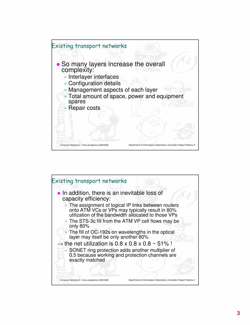
� So many layers increase the overall complexity:» Interlayer interfaces» Configuration details» Management aspects of each layer» Total amount of space, power and equipment
spares» Repair costs
Dipartimento di Informatica e Sistemistica, Università di Napoli Federico II Computer Networks II – Anno accademico 2008/2009
Existing transport networks
� In addition, there is an inevitable loss of capacity efficiency:» The assignment of logical IP links between routers
onto ATM VCs or VPs may typically result in 80% utilization of the bandwidth allocated to those VPs
» The STS-3c fill from the ATM VP cell flows may be only 80%
» The fill of OC-192s on wavelengths in the optical layer may itself be only another 80%
→ the net utilization is 0.8 x 0.8 x 0.8 ~ 51% !» SONET ring protection adds another multiplier of
0.5 because working and protection channels are exactly matched

4
Dipartimento di Informatica e Sistemistica, Università di Napoli Federico II Computer Networks II – Anno accademico 2008/2009
Existing transport networks
� The goal is to get a two layer model without losing the functionalities of the full stack
Pt-Pt DWDM
SONET
ATM
IP
fiber
DWDM-oxc& mesh surviv.
fiber
IP &GMPLS
Options:•Thin SONET•GFP / DW•10 GbE
Dipartimento di Informatica e Sistemistica, Università di Napoli Federico II Computer Networks II – Anno accademico 2008/2009
WDM
Wavelength Division Multiplexing
5
Dipartimento di Informatica e Sistemistica, Università di Napoli Federico II Computer Networks II – Anno accademico 2008/2009
WDM
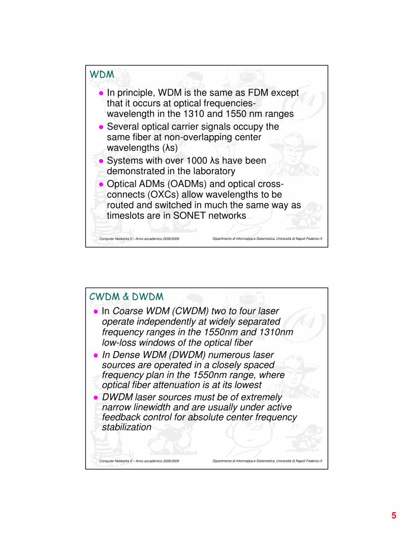
� In principle, WDM is the same as FDM except that it occurs at optical frequencies-wavelength in the 1310 and 1550 nm ranges
� Several optical carrier signals occupy the same fiber at non-overlapping center wavelengths (λs)
� Systems with over 1000 λs have been demonstrated in the laboratory
� Optical ADMs (OADMs) and optical cross-connects (OXCs) allow wavelengths to be routed and switched in much the same way as timeslots are in SONET networks
Dipartimento di Informatica e Sistemistica, Università di Napoli Federico II Computer Networks II – Anno accademico 2008/2009
CWDM & DWDM
� In Coarse WDM (CWDM) two to four laser operate independently at widely separated frequency ranges in the 1550nm and 1310nm low-loss windows of the optical fiber
� In Dense WDM (DWDM) numerous laser sources are operated in a closely spaced frequency plan in the 1550nm range, where optical fiber attenuation is at its lowest
� DWDM laser sources must be of extremely narrow linewidth and are usually under active feedback control for absolute center frequency stabilization
6
Dipartimento di Informatica e Sistemistica, Università di Napoli Federico II Computer Networks II – Anno accademico 2008/2009
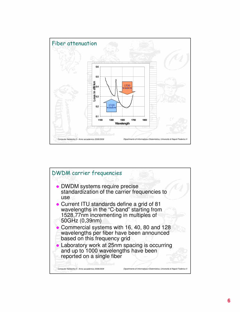
Fiber attenuation
0.1
0.2
0.3
0.4
0.5
0.6
1100 1300 1500 1700 1900
Wavelength
Lo
ss i
n d
B/k
m
1310window
1550window
Dipartimento di Informatica e Sistemistica, Università di Napoli Federico II Computer Networks II – Anno accademico 2008/2009
DWDM carrier frequencies
� DWDM systems require precise standardization of the carrier frequencies to use
� Current ITU standards define a grid of 81 wavelengths in the “C-band” starting from 1528,77nm incrementing in multiples of 50GHz (0,39nm)
� Commercial systems with 16, 40, 80 and 128 wavelengths per fiber have been announced based on this frequency grid
� Laboratory work at 25nm spacing is occurring and up to 1000 wavelengths have been reported on a single fiber
7
Dipartimento di Informatica e Sistemistica, Università di Napoli Federico II Computer Networks II – Anno accademico 2008/2009
Optical amplifiers
� An optical amplifier counteracts fiber attenuation over a complete band of lightwave channels at once
� Optical carriers are neither demodulated nor individually processed
� The most common type of OA is an erbium doped fiber amplifier (EDFA)
� EDFAs work well and are very efficient as amplifiers in the 1500nm range
� Light is pumped in at around 1400nm to excite the erbium ions, and then the incoming 1500nm light signal is amplified
Dipartimento di Informatica e Sistemistica, Università di Napoli Federico II Computer Networks II – Anno accademico 2008/2009
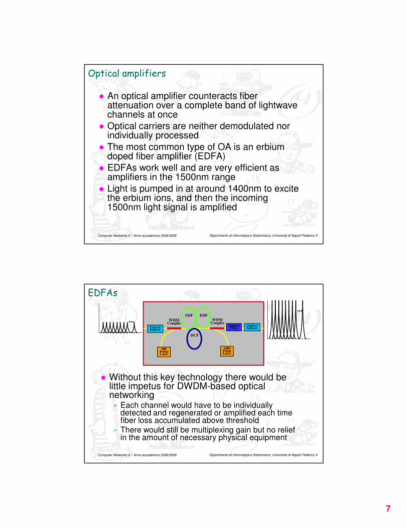
EDFAs
� Without this key technology there would be little impetus for DWDM-based optical networking» Each channel would have to be individually
detected and regenerated or amplified each time fiber loss accumulated above threshold
» There would still be multiplexing gain but no relief in the amount of necessary physical equipment
...
...
980PumpLaser
WDMCoupler
WDMCoupler
EDF
DCF
OpticalIsolator
1480PumpLaser
OpticalFilter
OpticalIsolator
EDF
8
Dipartimento di Informatica e Sistemistica, Università di Napoli Federico II Computer Networks II – Anno accademico 2008/2009
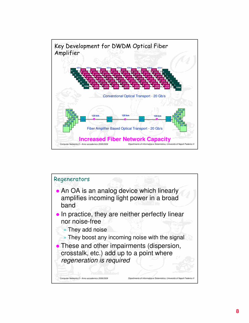
Key Development for DWDM Optical Fiber Amplifier
120 km
OC-48
OLS
TERM
OLS
RPTROLS
RPTR
OLS
TERM
120 km 120 km
Fiber Amplifier Based Optical Transport - 20 Gb/s
OC-48OC-48
OC-48
OC-48OC-48
OC-48OC-48
Conventional Optical Transport - 20 Gb/s
1310
RPTR
1310
RPTR
1310
RPTR
1310
RPTR
1310
RPTR
1310
RPTR
1310
RPTR
1310
RPTRTERM
TERM
40km 40km 40km 40km 40km 40km 40km 40km 40km
1310
RPTR
1310
RPTR
1310
RPTR
1310
RPTR
1310
RPTR
1310
RPTR
1310
RPTR
1310
RPTRTERM
TERM1310
RPTR
1310
RPTR
1310
RPTR
1310
RPTR
1310
RPTR
1310
RPTR
1310
RPTR
1310
RPTRTERM
TERM1310
RPTR
1310
RPTR
1310
RPTR
1310
RPTR
1310
RPTR
1310
RPTR
1310
RPTR
1310
RPTRTERM
TERM1310
RPTR
1310
RPTR
1310
RPTR
1310
RPTR
1310
RPTR
1310
RPTR
1310
RPTR
1310
RPTRTERM
TERM1310
RPTR
1310
RPTR
1310
RPTR
1310
RPTR
1310
RPTR
1310
RPTR
1310
RPTR
1310
RPTRTERM
TERM1310
RPTR
1310
RPTR
1310
RPTR
1310
RPTR
1310
RPTR
1310
RPTR
1310
RPTR
1310
RPTRTERM
TERM1310
RPTR
1310
RPTR
1310
RPTR
1310
RPTR
1310
RPTR
1310
RPTR
1310
RPTR
1310
RPTRTERM
TERM
OC-48OC-48
OC-48OC-48
OC-48OC-48
OC-48OC-48
Increased Fiber Network Capacity
Dipartimento di Informatica e Sistemistica, Università di Napoli Federico II Computer Networks II – Anno accademico 2008/2009
Regenerators
� An OA is an analog device which linearly amplifies incoming light power in a broad band
� In practice, they are neither perfectly linear nor noise-free
» They add noise
» They boost any incoming noise with the signal
� These and other impairments (dispersion, crosstalk, etc.) add up to a point where regeneration is required
9
Dipartimento di Informatica e Sistemistica, Università di Napoli Federico II Computer Networks II – Anno accademico 2008/2009
Regenerators
� In regeneration (as opposed to amplification):» Each channel is individually demodulated from its optical
carrier and converted to an electrical form
» Its bit-timing is extracted and used to sample the binary state of each symbol
» Jitter is removed from the recovered clock
» New 1/0 symbols are generated and remodulated onto a new outgoing carrier wavelength
� It is often used the term “3R” regenerators to refer to retiming, regenerating and retransmitting
Dipartimento di Informatica e Sistemistica, Università di Napoli Federico II Computer Networks II – Anno accademico 2008/2009
Regenerators
� Regeneration is a per-channel process involving electro-optical conversion and high-speed electrical processing of each channel
� It is therefore more costly than optical amplification
� In the design of DWDM links, regenerator spacings are typically around 550 to 600 km, being present OA spacings of around 60 to 80 km
� These spacings are not independent:» If OAs are more frequent, optical signal to noise
ratio will be better preserved allowing for a longer distance between regenerators

10
Dipartimento di Informatica e Sistemistica, Università di Napoli Federico II Computer Networks II – Anno accademico 2008/2009
Optical add/drop multiplexers (OADMs)
� OADMs almost completely follow from their SONET ADM predecessors
� In principle, an OADM can be based on» electronic detection of payloads
» electronic add/drop
» remodulation of pass-through and add signals onto new outgoing wavelengths
� Such an OADM is capable of full wavelength conversion as well as add/drop and pass-through functions» But it is desirable to leave pass-through channels
in the optical domain
Dipartimento di Informatica e Sistemistica, Università di Napoli Federico II Computer Networks II – Anno accademico 2008/2009
Optical add/drop multiplexers (OADMs)
� Many OADM designs are based on passive, purely-optical add/drop/through channel filters without any wavelength conversion» Only add/drop channels need to go through e-o
and o-e conversion (respectively)
� OADMs may be based on a waveband add/drop principle» Groups of 4 or 16 wavelengths are handled as a
whole for add or drop purposes, while the others pass on
� Reconfigurable OADMs (ROADMs) allow to:» Select any incoming channel to either drop or pass
on» Feed the outgoing multiplex from the incoming line
or the local add port
11
Dipartimento di Informatica e Sistemistica, Università di Napoli Federico II Computer Networks II – Anno accademico 2008/2009
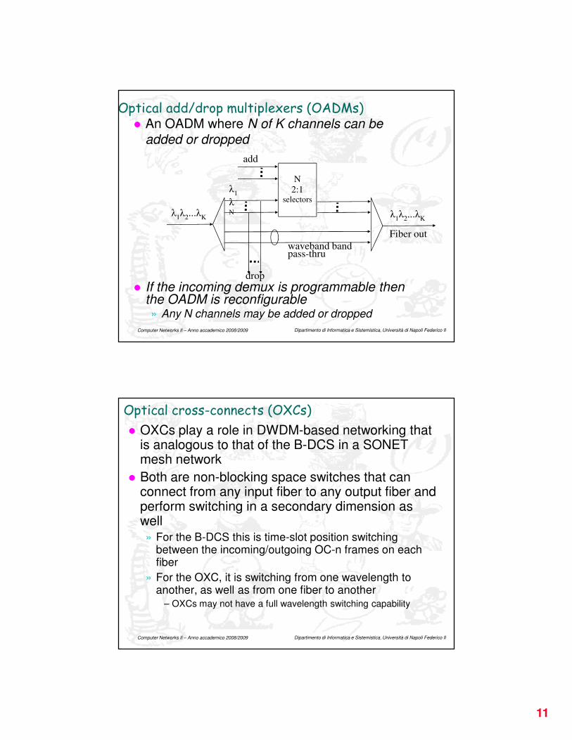
Optical add/drop multiplexers (OADMs)� An OADM where N of K channels can be
added or dropped
� If the incoming demux is programmable then the OADM is reconfigurable» Any N channels may be added or dropped
λ1
λ
Nλ1λ
2...λ
K λ1λ
2...λ
K
add
N2:1
selectors
drop
waveband bandpass-thru
Fiber out
Dipartimento di Informatica e Sistemistica, Università di Napoli Federico II Computer Networks II – Anno accademico 2008/2009
Optical cross-connects (OXCs)
� OXCs play a role in DWDM-based networking that is analogous to that of the B-DCS in a SONET mesh network
� Both are non-blocking space switches that can connect from any input fiber to any output fiber and perform switching in a secondary dimension as well» For the B-DCS this is time-slot position switching
between the incoming/outgoing OC-n frames on each fiber
» For the OXC, it is switching from one wavelength to another, as well as from one fiber to another
– OXCs may not have a full wavelength switching capability
12
Dipartimento di Informatica e Sistemistica, Università di Napoli Federico II Computer Networks II – Anno accademico 2008/2009
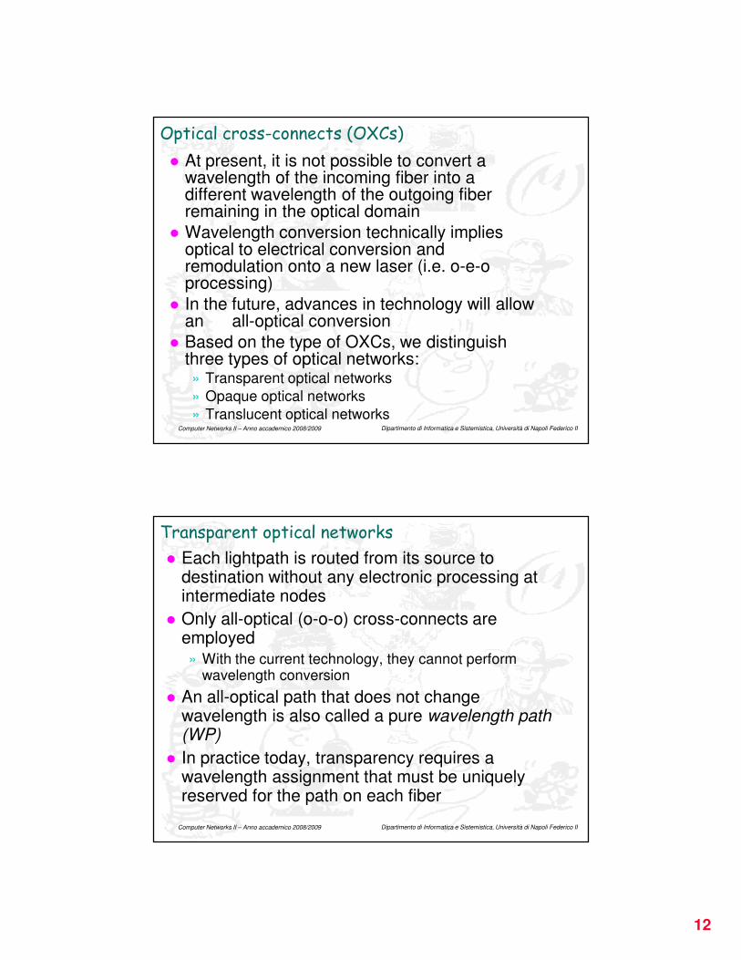
Optical cross-connects (OXCs)
� At present, it is not possible to convert a wavelength of the incoming fiber into a different wavelength of the outgoing fiber remaining in the optical domain
� Wavelength conversion technically implies optical to electrical conversion and remodulation onto a new laser (i.e. o-e-o processing)
� In the future, advances in technology will allow an all-optical conversion
� Based on the type of OXCs, we distinguish three types of optical networks:» Transparent optical networks
» Opaque optical networks
» Translucent optical networks
Dipartimento di Informatica e Sistemistica, Università di Napoli Federico II Computer Networks II – Anno accademico 2008/2009
Transparent optical networks
� Each lightpath is routed from its source to destination without any electronic processing at intermediate nodes
� Only all-optical (o-o-o) cross-connects are employed» With the current technology, they cannot perform
wavelength conversion
� An all-optical path that does not change wavelength is also called a pure wavelength path (WP)
� In practice today, transparency requires a wavelength assignment that must be uniquely reserved for the path on each fiber
13
Dipartimento di Informatica e Sistemistica, Università di Napoli Federico II Computer Networks II – Anno accademico 2008/2009
Transparent optical networks
� Pros:
» Transparency enables no dependency on the payload being in a specific format in terms of framing, bit-rate, line-coding, power level, jitter and so on, as is usually the case when electrical circuits have to handle the signal
» Wavelength converters (o-e-o cross-connects) are not needed
Dipartimento di Informatica e Sistemistica, Università di Napoli Federico II Computer Networks II – Anno accademico 2008/2009
Transparent optical networks
� Cons:» Wavelengths assignment is much more complex
because lightpaths must use the same wavelength end-to-end. The routing and wavelength assignment (RWA) problem is NP-hard
» To avoid wavelength blocking, the DWDM technology employed must support more wavelengths per fiber than a corresponding network where wavelengths can be reassigned at each node
» The lack of regeneration imposes limits on the length and routing of end-to-end paths to contain transmission impairments and loss
14
Dipartimento di Informatica e Sistemistica, Università di Napoli Federico II Computer Networks II – Anno accademico 2008/2009
Transparent optical networks
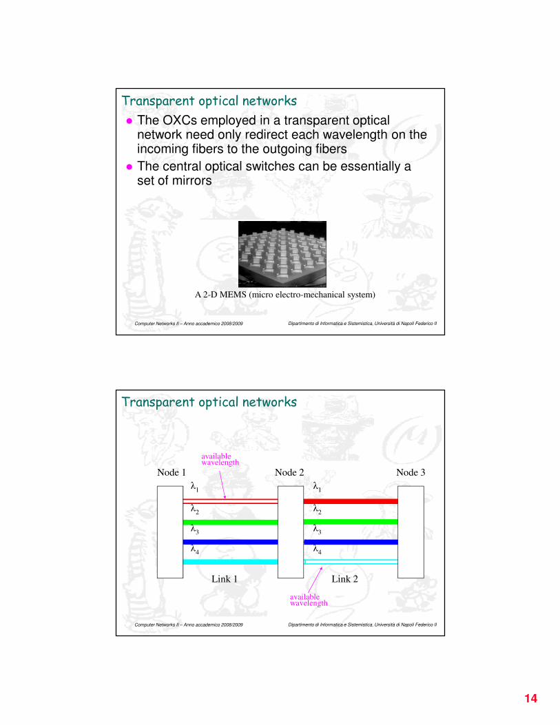
� The OXCs employed in a transparent optical network need only redirect each wavelength on the incoming fibers to the outgoing fibers
� The central optical switches can be essentially a set of mirrors
A 2-D MEMS (micro electro-mechanical system)
Dipartimento di Informatica e Sistemistica, Università di Napoli Federico II Computer Networks II – Anno accademico 2008/2009
Transparent optical networks
Link 1 Link 2
Node 1 Node 2 Node 3
λ1
λ2
λ3
λ4
λ1
λ2
λ3
λ4
available wavelength
available wavelength
15
Dipartimento di Informatica e Sistemistica, Università di Napoli Federico II Computer Networks II – Anno accademico 2008/2009
Transparent optical networks
Link 1 Link 2
Node 1 Node 2 Node 3
λ1
λ2
λ3
λ4
λ1
λ2
λ3
λ4
available wavelength
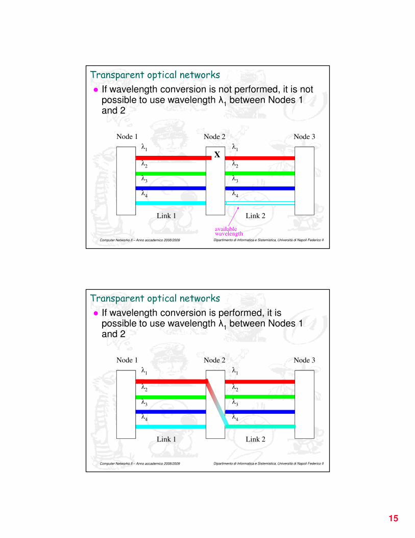
� If wavelength conversion is not performed, it is not possible to use wavelength λ
1between Nodes 1
and 2
X
Dipartimento di Informatica e Sistemistica, Università di Napoli Federico II Computer Networks II – Anno accademico 2008/2009
Transparent optical networks
Link 1 Link 2
Node 1 Node 2 Node 3
λ1
λ2
λ3
λ4
λ1
λ2
λ3
λ4
� If wavelength conversion is performed, it is possible to use wavelength λ
1between Nodes 1
and 2
16
Dipartimento di Informatica e Sistemistica, Università di Napoli Federico II Computer Networks II – Anno accademico 2008/2009
Transparent optical networks
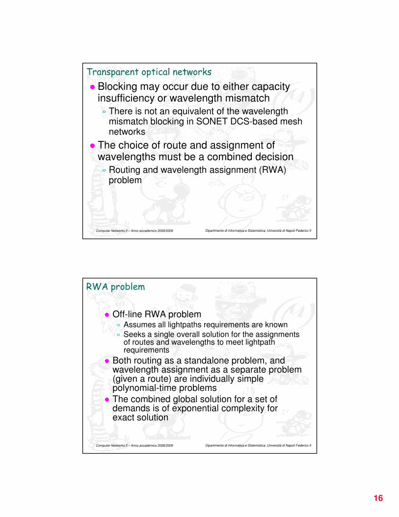
� Blocking may occur due to either capacity insufficiency or wavelength mismatch
» There is not an equivalent of the wavelength mismatch blocking in SONET DCS-based mesh networks
� The choice of route and assignment of wavelengths must be a combined decision
» Routing and wavelength assignment (RWA) problem
Dipartimento di Informatica e Sistemistica, Università di Napoli Federico II Computer Networks II – Anno accademico 2008/2009
RWA problem
� Off-line RWA problem» Assumes all lightpaths requirements are known
» Seeks a single overall solution for the assignments of routes and wavelengths to meet lightpath requirements
� Both routing as a standalone problem, and wavelength assignment as a separate problem (given a route) are individually simple polynomial-time problems
� The combined global solution for a set of demands is of exponential complexity for exact solution
17
Dipartimento di Informatica e Sistemistica, Università di Napoli Federico II Computer Networks II – Anno accademico 2008/2009
RWA problem
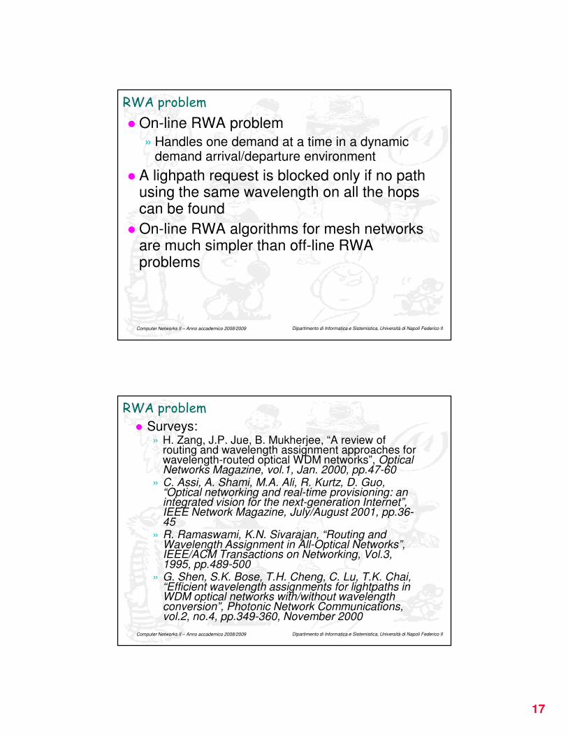
� On-line RWA problem
» Handles one demand at a time in a dynamic demand arrival/departure environment
� A lighpath request is blocked only if no path using the same wavelength on all the hops can be found
� On-line RWA algorithms for mesh networks are much simpler than off-line RWA problems
Dipartimento di Informatica e Sistemistica, Università di Napoli Federico II Computer Networks II – Anno accademico 2008/2009
RWA problem
� Surveys:» H. Zang, J.P. Jue, B. Mukherjee, “A review of
routing and wavelength assignment approaches for wavelength-routed optical WDM networks”, Optical Networks Magazine, vol.1, Jan. 2000, pp.47-60
» C. Assi, A. Shami, M.A. Ali, R. Kurtz, D. Guo, “Optical networking and real-time provisioning: an integrated vision for the next-generation Internet”, IEEE Network Magazine, July/August 2001, pp.36-45
» R. Ramaswami, K.N. Sivarajan, “Routing and Wavelength Assignment in All-Optical Networks”, IEEE/ACM Transactions on Networking, Vol.3, 1995, pp.489-500
» G. Shen, S.K. Bose, T.H. Cheng, C. Lu, T.K. Chai, “Efficient wavelength assignments for lightpaths in WDM optical networks with/without wavelength conversion”, Photonic Network Communications, vol.2, no.4, pp.349-360, November 2000
18
Dipartimento di Informatica e Sistemistica, Università di Napoli Federico II Computer Networks II – Anno accademico 2008/2009
Opaque optical networks
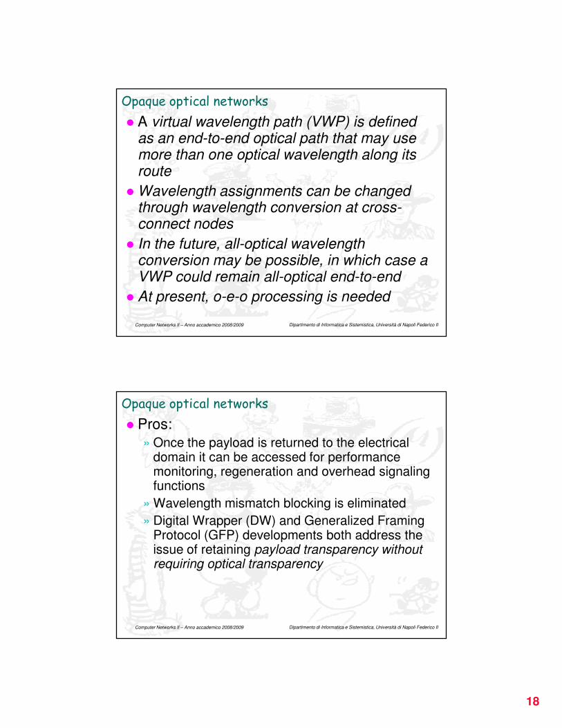
� A virtual wavelength path (VWP) is defined as an end-to-end optical path that may use more than one optical wavelength along its route
� Wavelength assignments can be changed through wavelength conversion at cross-connect nodes
� In the future, all-optical wavelength conversion may be possible, in which case a VWP could remain all-optical end-to-end
� At present, o-e-o processing is needed
Dipartimento di Informatica e Sistemistica, Università di Napoli Federico II Computer Networks II – Anno accademico 2008/2009
Opaque optical networks
� Pros:
» Once the payload is returned to the electrical domain it can be accessed for performance monitoring, regeneration and overhead signaling functions
» Wavelength mismatch blocking is eliminated
» Digital Wrapper (DW) and Generalized Framing Protocol (GFP) developments both address the issue of retaining payload transparency without requiring optical transparency
19
Dipartimento di Informatica e Sistemistica, Università di Napoli Federico II Computer Networks II – Anno accademico 2008/2009
Opaque optical networks
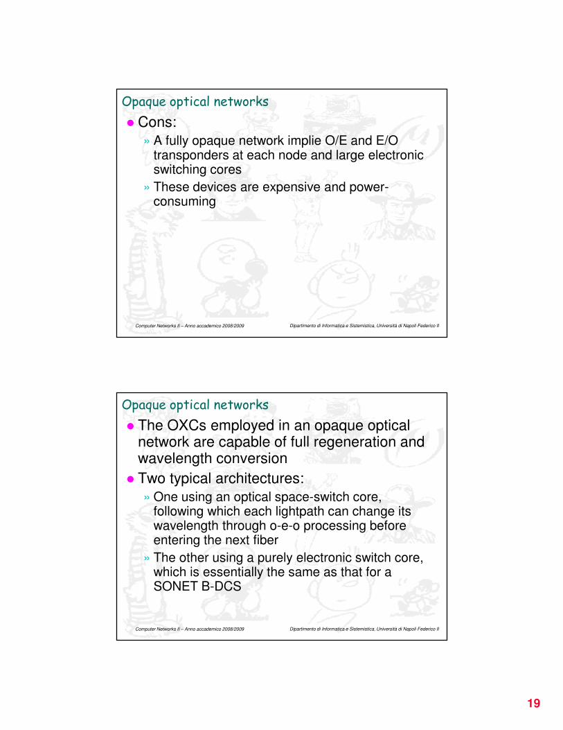
� Cons:
» A fully opaque network implie O/E and E/O transponders at each node and large electronic switching cores
» These devices are expensive and power-consuming
Dipartimento di Informatica e Sistemistica, Università di Napoli Federico II Computer Networks II – Anno accademico 2008/2009
Opaque optical networks
� The OXCs employed in an opaque optical network are capable of full regeneration and wavelength conversion
� Two typical architectures:
» One using an optical space-switch core, following which each lightpath can change its wavelength through o-e-o processing before entering the next fiber
» The other using a purely electronic switch core, which is essentially the same as that for a SONET B-DCS
20
Dipartimento di Informatica e Sistemistica, Università di Napoli Federico II Computer Networks II – Anno accademico 2008/2009
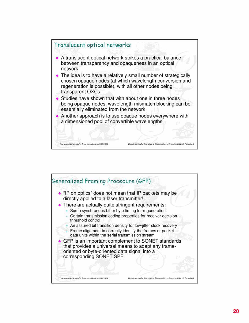
Translucent optical networks
� A translucent optical network strikes a practical balance between transparency and opaqueness in an optical network
� The idea is to have a relatively small number of strategically chosen opaque nodes (at which wavelength conversion and regeneration is possible), with all other nodes being transparent OXCs
� Studies have shown that with about one in three nodes being opaque nodes, wavelength mismatch blocking can be essentially eliminated from the network
� Another approach is to use opaque nodes everywhere with a dimensioned pool of convertible wavelengths
Dipartimento di Informatica e Sistemistica, Università di Napoli Federico II Computer Networks II – Anno accademico 2008/2009
Generalized Framing Procedure (GFP)
� “IP on optics” does not mean that IP packets may be directly applied to a laser transmitter!
� There are actually quite stringent requirements:» Some synchronous bit or byte timing for regeneration
» Certain transmission coding properties for receiver decision threshold control
» An assured bit transition density for low-jitter clock recovery
» Frame alignment to correctly identify the frames or packet data units within the serial transmission stream
� GFP is an important complement to SONET standards that provides a universal means to adapt any frame-oriented or byte-oriented data signal into a corresponding SONET SPE

21
Dipartimento di Informatica e Sistemistica, Università di Napoli Federico II Computer Networks II – Anno accademico 2008/2009
Gigabit Ethernet (GbE) and 10 Gb/s Ethernet (10GbE)
� GbE allows a 1 Gb/s point-to-point link over four pairs of Cat.5 UTPs to a maximum reach of 100m» GbE in practice abandons the textbook idea of
many sources accessing a media by CSMA/CD
» But it is not a format suitable for WAN transport
� 10GbE is being developed with direct WAN transport applications in mind» Exclusively a full-duplex point-to-point technology
(no CSMA/CD involved)
» Employs simplified SONET/SDH framing and scrambling in its WAN interface
Dipartimento di Informatica e Sistemistica, Università di Napoli Federico II Computer Networks II – Anno accademico 2008/2009
» Because the line rate of SONET OC-192 (or SDH STM-64) is within a few percent of 10 Gbps, GbE can use the same higher layer access protocols
» 10GbE is very cost-effective because existing OC-192 optics, laser drivers, clock recoveries, scrambling and decision circuits can all be reused for the 10GbE application
» Physical media specifications include 1310nm optics reaching 10km and 1550nm (single carrier) optics reaching 40km
Thus, 10GbE can be used as an access format from customer premises to a transport node
Gigabit Ethernet (GbE) and 10 Gb/s Ethernet (10GbE)
22
Dipartimento di Informatica e Sistemistica, Università di Napoli Federico II Computer Networks II – Anno accademico 2008/2009
IP-centric control of optical networks
� As IP is the dominant type of traffic, new transport techniques (e.g. 10GbE and GFP) are being developed to transport it over optics» These are ways in which IP has influenced the
data plane
� But another significant influence on transport networking has been the transfer and extension of ideas and techniques used for topology discovery, routing, and virtual circuit establishment by the Internet control plane
� The overall approach is usually referred to as “IP-centric control” of the transport network
Dipartimento di Informatica e Sistemistica, Università di Napoli Federico II Computer Networks II – Anno accademico 2008/2009
IP-centric control of optical networks
� Transport networks have traditionally been centrally controlled in terms of provisioning (and taking down) service paths as needed
� Transport path requirements grew or changed relatively slowly and centralized, even semi-manual, operations control was adequate
� One view of the future in transport networking is that high-end applications and major source/sinks of packet flows will “dial up” lightwave paths on demand and release them again
� The vision of a transport network operating in this “self-organizing” way can be supported by a distributed cooperation between nodes provided by explicit topology discovery and routing protocols used on the Internet
23
Dipartimento di Informatica e Sistemistica, Università di Napoli Federico II Computer Networks II – Anno accademico 2008/2009
T1/T3/OC3
FRS and CRS
ATM
Access
ATM
Access
ATM
Switch
Public/Private
Internet Peering
ATM
Access
ATM
Access
Access
Router
T1/T3 IP
Leased-Line
Connections
Core
Router
Core
Router
Access
Router
Access
Router
ATM Access
ATM Access
RAS
RAS
RAS
RAS
RAS
RAS
RAS
RAS
Access
Router
Access
Router
EtherSwitch
EtherSwitch
RAS
RAS
RAS
RAS
RAS
RAS
RAS
RAS
Core
Router
Core
Router
Backbone
SONET/WDMRAS Farms
T1/T3 FR
and ATM IP
Leased-Line
Connections
ATM
Switch
ATM
Switch
ATM
Switch
ATM
Switch
Core
Router
Core
Router
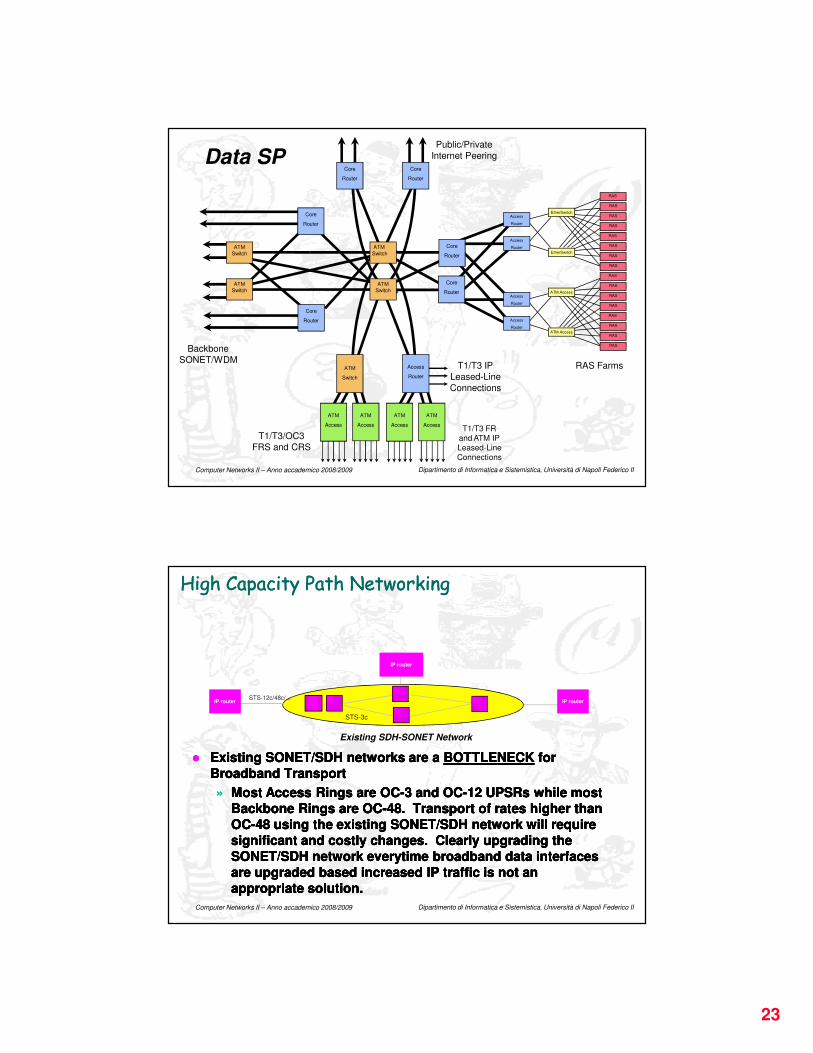
Data SP
Dipartimento di Informatica e Sistemistica, Università di Napoli Federico II Computer Networks II – Anno accademico 2008/2009
High Capacity Path NetworkingHigh Capacity Path Networking
�� Existing SONET/SDH networks are a Existing SONET/SDH networks are a BOTTLENECKBOTTLENECK for for
Broadband TransportBroadband Transport
»» Most Access Rings are OCMost Access Rings are OC--3 and OC3 and OC--12 UPSRs while most 12 UPSRs while most
Backbone Rings are OCBackbone Rings are OC--48. Transport of rates higher than 48. Transport of rates higher than
OCOC--48 using the existing SONET/SDH network will require 48 using the existing SONET/SDH network will require
significant and costly changes. Clearly upgrading the significant and costly changes. Clearly upgrading the
SONET/SDH network everytime broadband data interfaces SONET/SDH network everytime broadband data interfaces
are upgraded based increased IP traffic is not an are upgraded based increased IP traffic is not an
appropriate solution.appropriate solution.
Existing SDH-SONET Network
IP router
IP router IP router
STS-3c
STS-12c/48c/...
24
Dipartimento di Informatica e Sistemistica, Università di Napoli Federico II Computer Networks II – Anno accademico 2008/2009
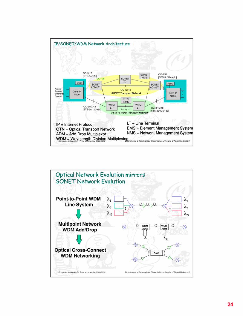
IP/SONET/WDM Network ArchitectureIP/SONET/WDM Network Architecture
Core IP
Node
EMS
.
.
.
SONET
ADM/LT
OC-3/12
[STS-3c/12c]
OC-12/48
OC-3/12
[STS-3c/12c/48c]
SONET Transport Network
SONET
NMS
Core IP
Node
EMS
.
.
.
Access Routers/EnterpriseServers
OC-48
SONET
ADM/LT
SONETXC
WDM
LT
WDM
LTλ1, λ2, ...
OC-3/12/48
[STS-3c/12c/48c]
Pt-to-Pt WDM Transport Network
OC-3/12/48
[STS-3c/12c/48c]
OTN
NMS
IP = Internet ProtocolIP = Internet Protocol
OTN = Optical Transport NetworkOTN = Optical Transport Network
ADM = Add Drop MultiplexorADM = Add Drop Multiplexor
WDM = Wavelength Division MultiplexingWDM = Wavelength Division Multiplexing
LT = Line TerminalLT = Line Terminal
EMS = Element Management SystemEMS = Element Management System
NMS = Network Management SystemNMS = Network Management System
Dipartimento di Informatica e Sistemistica, Università di Napoli Federico II Computer Networks II – Anno accademico 2008/2009
Optical Network Evolution mirrorsSONET Network EvolutionOptical Network Evolution mirrorsSONET Network Evolution
Multipoint Network
WDM Add/Drop
Point-to-Point WDM Line System
Optical Cross-ConnectWDM Networking
OXC
λi
WDM
ADM
WDM
ADM
λk
λ1
λ2
λΝ
λ1
λ2
λΝ
25
Dipartimento di Informatica e Sistemistica, Università di Napoli Federico II Computer Networks II – Anno accademico 2008/2009
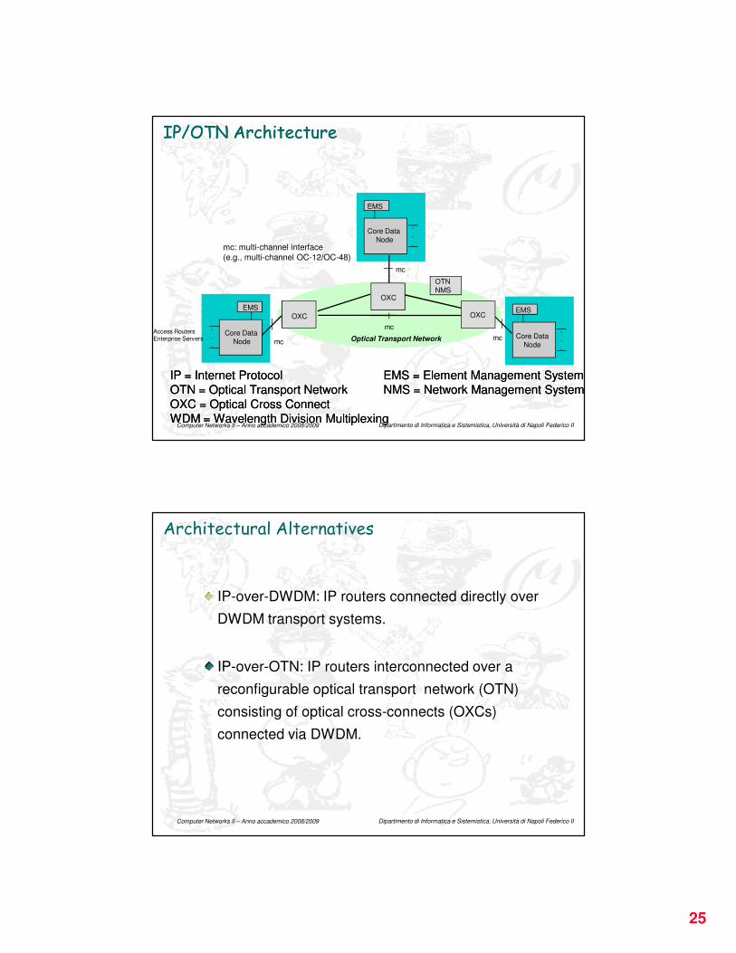
IP/OTN ArchitectureIP/OTN Architecture
Core Data
Node
EMS
.
.
.
OXC
mc: multi-channel interface
(e.g., multi-channel OC-12/OC-48)
mc
mcOptical Transport Network
OTN
NMS
Core Data
Node
EMS
.
.
.
Access RoutersEnterprise Servers
OXC
OXC
Core Data
Node
EMS
.
.
.
mc
mc
IP = Internet ProtocolIP = Internet Protocol
OTN = Optical Transport NetworkOTN = Optical Transport Network
OXC = Optical Cross ConnectOXC = Optical Cross Connect
WDM = Wavelength Division MultiplexingWDM = Wavelength Division Multiplexing
EMS = Element Management SystemEMS = Element Management System
NMS = Network Management SystemNMS = Network Management System
Dipartimento di Informatica e Sistemistica, Università di Napoli Federico II Computer Networks II – Anno accademico 2008/2009
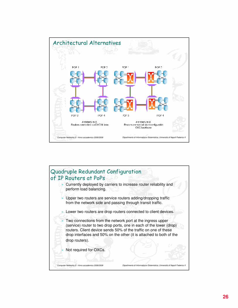
Architectural Alternatives
IP-over-DWDM: IP routers connected directly over
DWDM transport systems.
IP-over-OTN: IP routers interconnected over a
reconfigurable optical transport network (OTN)
consisting of optical cross-connects (OXCs)
connected via DWDM.
26
Dipartimento di Informatica e Sistemistica, Università di Napoli Federico II Computer Networks II – Anno accademico 2008/2009
Architectural Alternatives
Dipartimento di Informatica e Sistemistica, Università di Napoli Federico II Computer Networks II – Anno accademico 2008/2009
Quadruple Redundant Configuration of IP Routers at PoPs
» Currently deployed by carriers to increase router reliability and
perform load balancing.
» Upper two routers are service routers adding/dropping traffic
from the network side and passing through transit traffic.
» Lower two routers are drop routers connected to client devices.
» Two connections from the network port at the ingress upper
(service) router to two drop ports, one in each of the lower (drop)
routers. Client device sends 50% of the traffic on one of these
drop interfaces and 50% on the other (it is attached to both of the
drop routers).
» Not required for OXCs.

27
Dipartimento di Informatica e Sistemistica, Università di Napoli Federico II Computer Networks II – Anno accademico 2008/2009
IP-over-DWDM: Pros and Cons
» IP-routers with OC-48c/OC-192c interfaces
and aggregate throughput reaching 100s of
Gbps.
» Transport functions like switching,
configuration, and restoration are moved to
the IP layer and accomplished by protocols
like MPLS, thus providing a unifying
framework.
» IP routers control end-to-end path selection
using traffic engineering extended routing
and signaling IP protocols.
» Supports the peer-to-peer model where IP
routers interact as peers to exchange
routing information.
» Can router technology scale to
port counts consistent with
multi-terabit capacities without
compromising performance,
reliability, restoration speed,
and software stability ? A big
question mark.
ConsPros
Dipartimento di Informatica e Sistemistica, Università di Napoli Federico II Computer Networks II – Anno accademico 2008/2009
IP-over-OTN: Pros and Cons
» Reconfigurable optical backbone provides a flexible transport infrastructure
» Core OXC network can be shared with other service networks such as ATM, Frame Relay, and SONET/SDH
private line services.
» Allows interconnection of IP routers in
an arbitrary (logical) mesh topology.
– Not possible in architecture A since a
typical CO/PoP has two, in some
cases three, and in rare occasions
four conduits connecting it to
neighboring PoPs.
» Adding a reconfigurable optical backbone introduces an additional layer between the IP and DWDM layers and associated overhead.
» Traffic engineering occurs independently in two domains -- (i) the IP router network with its logical adjacencies spanning the OXC backbone, and (ii) the optical network which provisions physical lightpaths between edge IP routers. Could lead to inefficiency in traffic routing from a
global perspective.
ConsPros
28
Dipartimento di Informatica e Sistemistica, Università di Napoli Federico II Computer Networks II – Anno accademico 2008/2009
OSPF-TE [RFC3630]
� OSPF-TE refers to the extension of OSPF to have awareness of link and node attributes useful for “traffic engineering” purposes
» Link capacity and residual bandwidth
» An assigned link usage cost
» LER/LSR capability
» Wavelength channel cross-connection
» STS cross-connection
» Fiber level cross-connection
» Basic Packet Switch capability
Dipartimento di Informatica e Sistemistica, Università di Napoli Federico II Computer Networks II – Anno accademico 2008/2009
MPλS
� What has been called MPλS is based on the analogy between an LSP and a lightpath
» Both are “switched” path constructs that result in an inescapable sequence of relaying actions that direct any input to the predetermined output in a completely circuit-like way
� Thus MPλS is just MPLS where the label space of each link is simply the set of wavelength channels on the link
� The only difference is the switching fabric involved

29
Dipartimento di Informatica e Sistemistica, Università di Napoli Federico II Computer Networks II – Anno accademico 2008/2009
Generalized MPLS (GMPLS)
� GMPLS generalizes even more the concept of label: any transmission channel resource can be viewed as a generalized label
� GMPLS extends MPLS to provide the control plane (signaling and routing) for devices that switch in any of these domains: packet, time, wavelength, and fiber
» e.g. A router port ID, an ATM VPI/VCI, an STS-1 VT1.5 number, a fiber, a waveband, or a wavelength on a fiber can all be thought of as labels
� This common control plane promises to simplify network operation and management by automating end-to-end provisioning of connections, managing network resources, and providing the level of QoS that is expected in the new, sophisticated applications
Dipartimento di Informatica e Sistemistica, Università di Napoli Federico II Computer Networks II – Anno accademico 2008/2009
Generalized MPLS (GMPLS)
� GMPLS will also inherit the label-stacking feature of MPLS
» Allows aggregation of many small granularity LSPs into one high capacity LSP over a common segment of their routings
� In GMPLS this means that that several lightpaths may efficiently be merged into a single waveband path over the common segment
» This can permit lower-cost transport via OADMs with a waveband pass-through feature
� Label stacking also makes it possible to route through various regions or network domains where the entry and egress points are known but the internal routing details of the domains are not
» Entire subnetworks can be abstracted to single hops