Embed Size (px)
Citation preview
Modell der Diesellokomotive BR 217
22417F D GB USA NL

2
3
Inhaltsverzeichnis SeiteInformationen zum Vorbild 4Sicherheitshinweise 6Wichtige Hinweise 6Multiprotokollbetrieb 6Schaltbare Funktionen 9Parameter/Register 10Wartung und Instandhaltung 26Ersatzteile 30
Table of Contents Page Information about the prototype 4Safety Notes 11Important Notes 11Multi-Protocol Operation 11Controllable Functions 14Parameter/Register 15Service and maintenance 26Spare Parts 30
Sommaire PageInformations concernant la locomotive réelle 5Remarques importantes sur la sécurité 16Information importante 16Mode multiprotocole 16Fonctions commutables 19Paramètre/Registre 20Entretien et maintien 26Pièces de rechange 30
Inhoudsopgave PaginaInformatie van het voorbeeld 5Veiligheidsvoorschriften 21Belangrijke aanwijzing 21Multiprotocolbedrijf 21Schakelbare functies 24Parameter/Register 25Onderhoud en handhaving 26Onderdelen 30
4
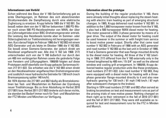
Informationen zum Vorbild Schon während des Baus der V 160-Serienlieferung gab es erste Überlegungen, im Rahmen des sich abzeichnenden Strukturwandels die Dampfheizung durch eine elektrische Zugheizung zu ersetzen. Krupp lieferte 1965 die V 162 001. Sie besaß neben dem von der V 160 her bekannten 1.900 PS-Mo-tor noch einen 500 PS-Heizdieselmotor von MAN, der über ein Zahnradgetriebe einen BBC-Drehstromgenerator antrieb. Die Leistung des Heizdiesels konnte aber im Sommer- oder Güterzugbetrieb zur Traktionsleistung mit herangezogen wer-den. Kurz darauf folgte im Februar 1966 die V 162 002 mit einem AEG-Generator und als letzte im Oktober 1966 die V 162 003. Sie besaß einen Siemens-Generator, der jedoch direkt am Heizdiesel angeflanscht war. Alle drei V 162 (ab 1968: 217) unterschieden sich von der V 160 äußerlich nur durch den um 400 mm verlängerten Rahmen sowie die geänderte Folge von Fenstern und Lüftungsgittern. 1968/69 folgten auf diese Prototypen zwölf ebenfalls von Krupp gebaute Serienmaschi-nen 217 011-022. Sie erhielten wie die V 162 003 einen direkt an den Heizdieselmotor angeflanschten Drehstromgenerator und zusätzlich neue hydraulische Getriebe für 130 km/h (nach Bremsanpassung später 140 km/h).Ab 1974 dienten die 217 001 und 002 häufig als Bremslokomo-tiven bei Test- und Messfahrten im Rahmen der Erprobung neuer Triebfahrzeuge. Bis zu ihrer Abstellung im Herbst 2010 (217 001) bzw. Herbst 2011 (217 002) änderte sich daran nichts, sie standen bei Bedarf immer noch für Test- und Messfahrten der FTZ Minden und München zur Verfügung.
Information about the prototypeDuring the building of the regular production V 160, there were already initial thoughts about replacing the steam heat-ing with electric train heating as part of emerging structural changes. In 1965, Krupp delivered road number V 162 001. In addition to the 1,900 horsepower motor known from the V 160, it also had a 500 horsepower MAN diesel motor for heating. This motor powered a BBC 3-phase generator by means of a gear drive. The output of the diesel motor for heating could be used however in the summer or with freight train service to boost motive power output. Shortly after that came road number V 162 002 in February of 1966 with an AEG generator and road number V 162 003 as the last unit in October of 1966. It had a Siemens generator that was flange-mounted directly to the diesel motor for heating. All three of the V 162 (start-ing in 1968: 217) differed from the V 160 externally only in the framed lengthened by 400 mm / 15-3/4” as well as the altered window and cooling grill arrangement. In 1968/69, Krupp de-livered twelve regular production units like these prototypes, road numbers 217 011-022. Like road number V 162 003, they were equipped with a diesel motor for heating with a three-phase generator flange-mounted directly to it and also new hydraulic gearing for 130 km/h / 81 mph (140 km/h / 87 mph after subsequent changes to the brakes).Starting in 1974 road numbers 217 001 and 002 often served as braking locomotives on test and measurement runs as part of the proving trials of new motive power. Nothing changed on them right up to their retirement in the fall of 2010 (217 001) and the fall of 2011 (217 002). They were still available as re-quired for test and measurement runs for the FTZ in Minden and Munich.
5
Informations concernant le modèle réel Dans le cadre de la restructuration qui s’annonçait, on com-mença déjà à réfléchir au remplacement du chauffage à va-peur par un chauffage de train électrique pendant la construc-tion en série de la V 160. Krupp livra la V 162 001 en 1965. Outre le moteur de 1900 ch connu de la V 160, elle était également équipée d’un moteur diesel pour le chauffage de 500 ch de MAN qui, via un engrenage, entraînait un alternateur BBC. Pour l’exploitation estivale ou de trains marchandises, le ren-dement du moteur diesel supplémentaire pouvait toutefois être mis à contribution pour la traction Peu après, en février 1966, suivit la V 162 002 avec un générateur AEG, puis la dernière, la V 162 003, en octobre 1966. Elle était équipée d’un générateur Siemens, toutefois directement bridé sur le moteur diesel. Les trois V 1623 (à partir de 1968 : 217) se distinguaient extérieure-ment de la V 160 uniquement par leur châssis rallongé de 400 mm ainsi que par la disposition des fenêtres et grilles d’aération. En 1968/69, ces prototypes furent suivis de 12 machines de série également construites par Krupp, 217 011 à 022. Tout comme la V 162 003, elle furent dotées d’un alternateur directement bridé sur le moteur diesel de chauffe ainsi que de nouvelles transmissions hydrauliques pour une vitesse de 130 km/h (puis, après adaptation des freins, 140 km/h).A partir de 1974, les machines 217 001 et 002 servirent sou-vent de locomotives de freinage pour les marches test et marches de mesure dans le cadre des essais de nouveaux engins de traction. Jusqu’à ce qu’elles fussent garées, à l’au-tomne 2010 (217 001) resp. automne 2011 (217 002), la situation resta inchangée, elles restaient toujours disponibles pour des marches d’essai et de mesure de la FTZ Minden et Munich si besoin.
Informatie van het voorbeeldAl tijdens de bouw van de V 160-serie werd voor het eerst over-wogen om, in het kader van de zich aftekenende structuur-verandering, de stoomverwarming te vervangen door elek-trische treinverwarming. Krupp leverde in 1965 de V 162 001. Deze had, naast de uit de V 160 bekende 1.900 pk motor, nog een 500 pk MAN-dieselmotor voor verwarming, die via een tandwielaandrijving een BBC-dynamo aandreef. Het vermo-gen van de verwarmingsdiesel kon echter bij gebruik in de zomer of in het goederenvervoer worden ingeschakeld voor extra tractievermogen. Kort daarop volgde in februari 1966 de V 162 002 met een AEG-dynamo en ten slotte in oktober 1966 de V 162 003. Deze was voorzien van een Siemens-dy-namo, die echter met een flensverbinding direct op de ver-warmingsdiesel was aangebracht. Alle drie de versies van de V 162 (vanaf 1968: 217) verschilden uiterlijk alleen van de V 160 door het 400 mm langere frame en door de veranderde volgorde van ruiten en ventilatieroosters. In 1968/69 volgden op deze prototypes twaalf eveneens door Krupp gebouwde seriemachines, de 217 011-022. Deze kregen, net zoals de V 162 003, een met een flensverbinding direct op de verwar-mingsdieselmotor bevestigde dynamo en bovendien nieuwe hydraulische aandrijvingen, om snelheden van 130 km/u (na een aanpassing van de remmen later 140 km/u) te bereiken.Vanaf 1974 dienden de 217 001 en 002 vaak als remlocomo-tieven bij test- en meetritten in het kader van het testen van nieuwe krachtvoertuigen. Tot hun buitenbedrijfstelling in de herfst van 2010 (217 001) resp. herfst van 2011 (217 002) veranderde dat niet. Indien nodig waren ze nog steeds be-schikbaar voor test- en meetritten van de FTZ Minden und München.
6
Sicherheitshinweise • DieLokdarfnurmiteinemdafürbestimmtenBetriebssys-
tem eingesetzt werden.• Analogmax.15Volt=,digitalmax.22Volt~.• DieLokdarfnurauseinerLeistungsquelleversorgt
werden.• BeachtenSieunbedingtdieSicherheitshinweiseinder
Bedienungsanleitung zu Ihrem Betriebssystem.• FürdenkonventionellenBetriebderLokmussdasAn-
schlussgleis entstört werden. Dazu ist das Entstörset 611 655 zu verwenden. Für Digitalbetrieb ist das Entstör-set nicht geeignet.
• ACHTUNG! Funktionsbedingte scharfe Kanten und Spitzen.• SetzenSiedasModellkeinerdirektenSonneneinstrah-
lung, starken Temperaturschwankungen oder hoher Luftfeuchtigkeit aus.
• VerbauteLED`sentsprechenderLaserklasse1nachNorm EN 60825-1.
Wichtige Hinweise • DieBedienungsanleitungunddieVerpackungsind
Bestandteile des Produktes und müssen deshalb aufbe-wahrt sowie bei Weitergabe des Produktes mitgegeben werden.
• FürReparaturenoderErsatzteilewendenSiesichbitteanIhren Trix-Fachhändler.
• GewährleistungundGarantiegemäßderbeiliegendenGarantieurkunde.
• Entsorgung:www.maerklin.com/en/imprint.html
• DervolleFunktionsumfangistnurunterTrixSystems,DCC und unter mfx verfügbar.
• Eingebaute,fahrtrichtungsabhängigeStirnbeleuchtung. Im Digitalbetrieb schaltbar.
• BefahrbarerMindestradius360mm.
Multiprotokollbetrieb AnalogbetriebDer Decoder kann auch auf analogen Anlagen oder Gleis-abschnitten betrieben werden. Der Decoder erkennt die analoge Gleichspannung (DC) automatisch und passt sich der analogen Gleisspannung an. Es sind alle Funktionen, die unter mfx oder DCC für den Analogbetrieb eingestellt wurden aktiv (siehe Digitalbetrieb).
DigitalbetriebDer Decoder ist ein Multiprotokolldecoder. Der Decoder kann unter folgenden Digital-Protokollen eingesetzt werden: mfx oder DCC. Das Digital-Protokoll mit den meisten Möglichkeiten ist das höchstwertige Digital-Protokoll. Die Reihenfolge der Digital-Protokolle ist in der Wertung fallend: Priorität 1: mfx Priorität 2: DCC Priorität 3: DCHinweis: Werden zwei oder mehrere Digital-Protokolle am Gleis erkannt, übernimmt der Decoder automatisch das höchstwertige Digital-Protokoll; z.B. wird mfx & DCC erkannt wird das mfx-Digital-Protokoll vom Decoder übernommen. Einzelne Protokolle können über den Parameter CV 50 deaktiviert werden.
7
Hinweis: Beachten Sie, dass nicht alle Funktionen in allen Digital-Protokollen möglich sind. Unter mfx und DCC können einige Einstellungen von Funktionen, welche im Analog-Betrieb wirksam sein sollen, vorgenommen werden.
Hinweise zum Digitalbetrieb • DiegenaueVorgehensweisezumEinstellenderdiversen
Parameter entnehmen Sie bitte der Bedienungsanleitung Ihrer Mehrzug-Zentrale.
• DerBetriebmitgegenpoligerGleichspannungimBremsabschnitt ist mit der werkseitigen Einstellung nicht möglich. Ist diese Eigenschaft gewünscht, so muss auf den konventionellen Gleichstrombetrieb verzichtet werden(CV29/Bit2=0).
mfx-Protokoll
Adressierung • KeineAdresseerforderlich,jederDecodererhälteine
einmalige und eindeutige Kennung (UID).• DerDecodermeldetsichaneinerCentralStationoder
Mobile Station mit seiner UID automatisch an.• NameabWerk:217 014-0 DB AG
Programmierung• DieEigenschaftenkönnenüberdiegrafischeOberfläche
der Central Station bzw. teilweise auch mit der Mobile Station programmiert werden.
• EskönnenalleConfigurationVariablen(CV)mehrfachgelesen und programmiert werden.
• DieProgrammierungkannentwederaufdemHaupt-oderdem Programmiergleis erfolgen.
• DieDefaulteinstellungen(Werkseinstellungen)könnenwieder hergestellt werden.
• Funktionsmapping:FunktionenkönnenmitHilfederCentral Station 60212 (eingeschränkt) und mit der Central Station 60213/60214/60215/60216/60226 beliebigen Funkti-onstasten zugeordnet werden (siehe Hilfe in der Central Station).
8
DCC-Protokoll
Adressierung• MöglicheAdressen:Kurze,langeundTraktionsadresse• Adressbereich:
1 – 127 (kurze Adresse, Traktionsadresse) 1 – 10239 (lange Adresse)• JedeAdresseistmanuellprogrammierbar.• KurzeoderlangeAdressewirdüberdieCVsausgewählt.• EineangewandteTraktionsadressedeaktiviertdie
Standard-Adresse.
Programmierung• DieEigenschaftenkönnenüberdieConfigurationsVari-
ablen (CV) mehrfach geändert werden. • DieCV-NummerunddieCV-Wertewerdendirekteinge-
geben.• DieCVskönnenmehrfachgelesenundprogrammiert
werden (Programmierung auf dem Programmiergleis).• DieCVskönnenbeliebigprogrammiertwerden.PoM
(Programmierung auf dem Hauptgleis PoM) ist nur bei den in der CV-Tabelle gekennzeichneten CV möglich. PoM muss von Ihrer Zentrale unterstützt werden (siehe Bedienungsanleitung ihres Gerätes).
• DieDefaulteinstellungen(Werkseinstellungen)könnenwieder hergestellt werden.
• 14bzw.28/126Fahrstufeneinstellbar.• AlleFunktionenkönnenentsprechenddemFunktions-
mapping geschaltet werden.• WeitereInformation,sieheCV-TabelleDCC-Protokoll.
Es wird empfohlen, die Programmierungen grundsätzlich auf dem Programmiergleis vorzunehmen.
Logische Funktionen
Anfahr-/Bremsverzögerung• DieBeschleunigungs-undBremszeitkönnengetrennt
von einander eingestellt werden. • DielogischeFunktionsabschaltungABVkannüberdas
Funktionsmapping auf jede beliebige Funktionstaste gelegt werden.
9
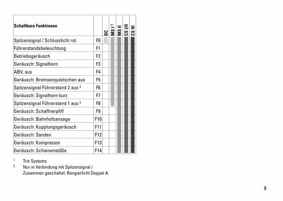
Schaltbare Funktionen
DC
MS
I 1
MS
IICS
I/II
CS II
I
Spitzensignal / Schlusslicht rot F0
Führerstandsbeleuchtung F1
Betriebsgeräusch F2
Geräusch: Signalhorn F3
ABV, aus F4
Geräusch: Bremsenquietschen aus F5
Spitzensignal Führerstand 2 aus 2 F6
Geräusch: Signalhorn kurz F7
Spitzensignal Führerstand 1 aus 2 F8
Geräusch: Schaffnerpfiff F9
Geräusch: Bahnhofsansage F10
Geräusch: Kupplungsgeräusch F11
Geräusch: Sanden F12
Geräusch: Kompressor F13
Geräusch: Schienenstöße F14
1 Trix Systems2 Nur in Verbindung mit Spitzensignal / Zusammen geschaltet: Rangierlicht Doppel A.

10
CV Bedeutung Wert DCC ab Werk 1 Adresse 1 - 127 3 2 PoM Minimalgeschwindigkeit 0 - 255 33 PoM Anfahrverzögerung 0 - 255 154 PoM Bremsverzögerung 0 - 255 155 PoM Maximalgeschwindigkeit 0 - 255 1758 Werkreset/Herstellerkennung 8 131
13 PoM Funktionen F1 - F8 im Analogbetrieb 0 - 255 014 PoM Funktionen F9 - F15 und Licht im Analogbetrieb 0 - 255 117 Erweiterte Adresse (oberer Teil) CV29,Bit5=1 19218 Erweiterte Adresse (unterer Teil) CV29,Bit5=1 12819 Traktionsadresse 0 - 255 021 PoM Funktionen F1 - F8 bei Traktion 0 - 255 022 PoM Funktionen F9 - F15 und Licht bei Traktion 0 - 255 0
29 PoM
Bit 0: Umpolung Fahrtrichtung Bit 1: Anzahl Fahrstufen 14 oder 28/128* Bit 2: DCC Betrieb mit Bremsstrecke (kein Analogbetrieb möglich) Bit 5: kurze / lange Adresse
0 / 1 0 / 2 0 / 4 0 / 32
0, 1, 2, 3, 4, 5, 6, 7, 32, 34, 35, 36, 37,
38, 396
50 PoM
Alternative Protokolle (DCC kann sich selber nicht deaktivieren)Bit0:AnalogACaus=0/AnalogACein=1 Bit1:AnalogDCaus=0/AnalogDCein=1 Bit2:fx(MM)aus=0/fx(MM)ein=1 Bit3:mfxaus=0/mfxein=1
0 / 1 0 / 2 0 / 4 0 / 8
0 - 15 15
63 PoM Lautstärke 0 - 255 255
* Fahrstufen am Lokdecoder und am Steuergerät müssen übereinstimmen, es sind sonst Fehlfunktionen möglich.
11
• Built-inheadlightsthatchangeoverwiththedirectionoftravel. They can be turned on and off in digital operation.
• Minimumradiusforoperationis360mm/14-3/16“.
Multi-Protocol Operation Analog OperationThis decoder can also be operated on analog layouts or ar-eas of track that are analog. The decoder recognizes alter-nating current (DC) and automatically adapts to the analog track voltage. All functions that were set under mfx or DCC for analog operation are active (see Digital Operation).
Digital OperationThe decoders are multi-protocol decoders. These decoders can be used under the following digital protocols: mfx or DCC.The digital protocol with the most possibilities is the highest order digital protocol. The sequence of digital protocols in descending order is: Priority 1: mfx Priority 2: DCC Priority 3: DCNote: If two or more digital protocols are recognized in the track, the decoder automatically takes on the highest value digital protocol.For example, if mfx & DCC are recognized, the mfx digital protocol is taken on by the decoder. Individual protocols can be deactivated with Parameter CV 50.Note: Please note that not all functions are possible in all digital protocols. Several settings for functions, which are supposed to be active in analog operation, can be done under mfx and DCC.
Safety Notes• Thislocomotiveisonlytobeusedwiththeoperating
system it is designed for.• Analogmax.15voltsDC,digitalmax.22voltsAC.• Thislocomotivemustneverbesuppliedwithpowerfrom
more than one power pack.• Pleasemakenoteofthesafetynotesintheinstructions
for your operating system.• Thefeedertrackmustbeequippedtopreventinter-
ference with radio and television reception, when the locomotive is to be run in conventional operation. The 611 655 interference suppression set is to be used for this purpose. The interference suppression set is not suitable for digital operation.
• WARNING! Sharp edges and points required for operation.• Donotexposethemodeltodirectsunlight,extreme
changes in temperature, or high humidity. • TheLEDsinthisitemcorrespondtoLaserClass1accor-
ding to Standard EN 60825-1.
Important Notes• Theoperatinginstructionsandthepackagingareacom-
ponent part of the product and must therefore be kept as well as transferred along with the product to others.
• PleaseseeyourauthorizedTrixdealerforrepairsorspare parts.
• Thewarrantycardincludedwiththisproductspecifiesthe warranty conditions.
• Disposing:www.maerklin.com/en/imprint.html• ThefullrangeoffunctionsisonlyavailableunderTrix
Systems and under DCC and mfx.
12
Notes on digital operation • Theoperatinginstructionsforyourcentralunitwillgive
you exact procedures for setting the different parame-ters.
• Thesettingdoneatthefactorydoesnotpermitoperationwith opposite polarity DC power in the braking block. If you want this characteristic, you must do without conventionalDCpoweroperation(CV29/Bit2=0).
mfx Protocol
Addresses • Noaddressisrequired;eachdecoderisgivenaone-
time, unique identifier (UID).• ThedecoderautomaticallyregistersitselfonaCentral
Station or a Mobile Station with its UID.• Namesetatthefactory:217 014-0 DB AG
Programming • Thecharacteristicscanbeprogrammedusingthe
graphic screen on the Central Station or also partially with the Mobile Station.
• AlloftheConfigurationVariables(CV)canbereadandprogrammed repeatedly.
• Theprogrammingcanbedoneeitheronthemaintrackorthe programming track.
• Thedefaultsettings(factorysettings)canbeproducedrepeatedly.
• Functionmapping:Functionscanbeassignedtoany of the function buttons with the help of the 60212 Central Station (with limitations) and with the 60213/60214/60215/60216/60226 Central Station (See help section in the Central Station).
13
DCC Protocol
Addresses • Possibleaddresses:short,long,andm.u.address• Addressrange:
1 – 127 (short address, m.u. address) 1 – 10239 (long address)
• Everyaddresscanbeprogrammedmanually.• AshortoralongaddressisselectedusingtheCVs.• Amultipleunitaddressthatisbeinguseddeactivatesthe
standard address.
Programming• Thecharacteristicscanbechangedrepeatedlyusingthe
Configuration Variables (CV).• TheCVnumbersandtheCVvaluesareentereddirectly.• TheCVscanbereadandprogrammedrepeatedly.(Pro-
gramming is done on the programming track.)• TheCVscanbeprogrammed,asyoudesire.PoM(Pro-
gramming on the layout track) is only possible with those CVs marked in the CV table. PoM must be supported by your central controller (see the instructions for your controller).
• Thedefaultsettings(factorysettings)canbeproducedrepeatedly.
• 14or28/126speedlevelscanbeset.• Allofthefunctionscanbecontrolledaccordingtothe
function mapping (see CV description).• SeetheCVdescriptionfortheDCCprotocolforadditional
information.
We recommend that in general programming should be done on the programming track.
Logic Functions
Acceleration / Braking Delay• Theaccelerationandbrakingtimescanbesetseparately
from each other. • ThelogicalfunctionshutoffforABV(Acceleration/
Braking Delay) can be assigned to any function button by means of function mapping.
14
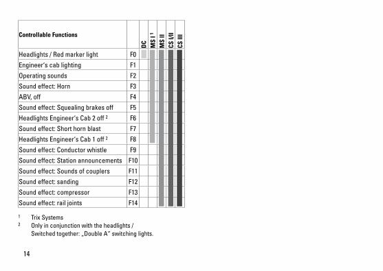
Controllable Functions
DC
MS
I 1
MS
IICS
I/II
CS II
I
Headlights / Red marker light F0
Engineer‘s cab lighting F1
Operating sounds F2
Sound effect: Horn F3
ABV, off F4
Sound effect: Squealing brakes off F5
Headlights Engineer‘s Cab 2 off 2 F6
Sound effect: Short horn blast F7
Headlights Engineer‘s Cab 1 off 2 F8
Sound effect: Conductor whistle F9
Sound effect: Station announcements F10
Sound effect: Sounds of couplers F11
Sound effect: sanding F12
Sound effect: compressor F13
Sound effect: rail joints F14
1 Trix Systems2 Only in conjunction with the headlights / Switchedtogether:„DoubleA“switchinglights.
15
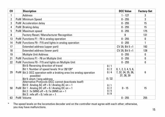
* The speed levels on the locomotive decoder and on the controller must agree with each other; otherwise, you may have malfunctions.
CV Discription DCC Value Factory-Set 1 Address 1 - 127 3 2 PoM Minimum Speed 0 - 255 33 PoM Acceleration delay 0 - 255 154 PoM Braking delay 0 - 255 155 PoM Maximum speed 0 - 255 1758 Factory Reset / Manufacturer Recognition 8 131
13 PoM Functions F1 - F8 in analog operation 0 - 255 014 PoM Functions F9 - F15 and lights in analog operation 0 - 255 117 Extended address (upper part) CV29,Bit5=1 19218 Extended address (lower part) CV29,Bit5=1 12819 Multiple Unit Address 0 - 255 021 PoM Functions F1 - F8 on Multiple Unit 0 - 255 022 PoM Functions F9 - F15 and lights on Multiple Unit 0 - 255 0
29 PoM
Bit 0: Reversing direction of travel Bit 1: Number of speed levels 14 or 28/128*Bit 2: DCC operation with a braking area (no analog operation possible) Bit 5: short / long address
0 / 1 0 / 2 0 / 4
0 / 32
0, 1, 2, 3, 4, 5, 6, 7, 32, 34, 35, 36,
37, 38, 396
50 PoM
Alternative Protocols (DCC cannot deactivate itself) Bit0:AnalogACoff=0/AnalogACon=1 Bit1:AnalogDCoff=0/AnalogDCon=1 Bit2:fx(MM)off=0/fx(MM)on=1 Bit3:mfxoff=0/mfxon=1
0 / 1 0 / 2 0 / 4 0 / 8
0 - 15 15
63 PoM Volume 0 - 255 255
16
Remarques importantes sur la sécurité • Lalocomotivenepeutêtreutiliséequ‘aveclesystème
d‘exploitation indiqué.• Analogiquemax.15Volt=,digitalmax.22Volt~.• Lalocomotivenepeutpasêtrealimentéeélectriquement
par plus d‘une source de courant à la fois.• Ilestimpératifdetenircomptedesremarquessurla
sécurité décrites dans le mode d‘emploi de votre système d‘exploitation.
• Pour l’exploitation de la locomotive en mode convention-nel, la voie de raccordement doit être déparasitée. A cet effet, utiliser le set de déparasitage réf. 611 655. Le set de déparasitage ne convient pas pour l’exploitation en mode numérique.
• ATTENTION! Pointes et bords coupants lors du fonctionne-ment du produit.
• Nepasexposerlemodèleàunensoleillementdirect,à de fortes variations de température ou à un taux d‘humidité important.
• LesDELinstalléescorrespondentàlaclasselaser1selon la norme EN 60825-1.
Information importante• Lanoticed‘utilisationetl’emballagefontpartieintégrante
du produit ; ils doivent donc être conservés et, le cas échéant, transmis avec le produit.
• Pourtouteréparationouremplacementdepièces,adres-sez vous à votre détaillant-spécialiste Trix.
• Garantielégaleetgarantiecontractuelleconformémentau certificat de garantie ci-joint.
• Elimination:www.maerklin.com/en/imprint.html• L’intégralitédesfonctionsestdisponibleuniquementen
exploitation Trix Systems, DCC et mfx. • Feuxdesignalisations‘inversantselonlesensdemar-
che; feux commutables en exploitation digital. • Rayonminimald’inscriptionencourbe360mm.
Mode multiprotocole Mode analogiqueOn peut aussi faire fonctionner le décodeur sur des instal-lations ou des sections de voie analogiques. Le décodeur identifie automatiquement la tension de voie analogique (DC). Toutes les fonctions qui ont été paramétrée pour le mode analogique sous mfx ou sous DCC sont actives (voir mode numérique).
Mode numériqueLes décodeur sont des décodeur multiprotocole. Le décodeur peut être utilisé avec les protocoles numériques suivants : mfx, DCCLe protocole numérique offrant les possibilités les plus nombreuses est le protocole numérique à bit de poids fort. La hiérarchisation des protocoles numériques est descendante : Priorité 1 : mfx Priorité 2 : DCC Priorité 3 : DCIndication : Si deux ou plus de deux protocoles numériques sont reconnus sur la voie, le décodeur choisit automatique-ment le protocole numérique le plus significatif. Entre les
17
protocoles mfx & DCC par exemple, le décodeur choisira le protocole numérique mfx. Vous pouvez désactiver les différents protocoles via le paramètre CV 50.Indication : remarquez que toutes les fonctions ne peuvent pas être actionnées dans tous les protocoles numériques. Sous mfx et sous DCC, il est possible de procéder à quelques paramétrages de fonctions devant être actives dans le cadre de l’exploitation analogique.
Remarques relatives au fonctionnement en mode digital • Encequiconcernelaprocédurederéglagedesdivers
paramètres, veuillez vous référer au mode d‘emploi de votre centrale de commande multitrain.
• L’exploitationaveccourantcontinudepolaritéinversedans les sections de freinage n’est pas possible avec le réglage d’usine. Si cette propriété est désirée, il faut alors renoncer à l’exploitation conventionnelle en cou-rantcontinu(CV29/Bit2=0).
Protocole mfx
Adressage • Aucuneadressen’estnécessaire,ledécodeurreçoittou-
tefois une identification unique et non équivoque (UID).• AvecsonUID,ledécodeurindiqueautomatiquement
à une station centrale ou à une station mobile qu’il est connecté.
• Nomencodeeenusine:217 014-0 DB AG
Programmation• Lescaractéristiquespeuventêtreprogramméespar
l’intermédiaire de la couche graphique de la station cen-trale, voire en partie aussi au moyen de la station mobile.
• Touteslesconfigurationsvariables(CV)peuventêtrelueset programmées de façon réitérée.
• Laprogrammationpeutêtreréaliséesoitsurlavoieprincipale, soit sur la voie de programmation.
• Lesparamétragespardéfaut(paramétragesusine)peuvent être rétablis.
• Mappagedesfonctions:lesfonctionspeuventêtreaffectées à de quelconques touches de fonction au moyen de la station centrale (60212) (restreinte) et avec la station centrale 60213/60214/60215/60216/60226 (voir Aide au niveau de la station centrale).
18
Protocole DCC
Adressage• Adressepossibles:Courtes,longuesetadressesdetraction• Catégoried’adresse:
1 à 127 (adresses courtes, adresses de traction) 1 à 10239 (adresses longues)
• Chaqueadresseestprogrammablemanuellement.• L’adressebrèveoulongueestchoisieparl’intermédiaire
des CVs.• Uneadressedetractionutiliséedésactivel’adresse
standard.
Programmation• Lescaractéristiquespeuventêtremodifiéesdefaçon
réitérée par l’intermédiaire des variables de configuration (CVs).
• Touteslesconfigurationsvariables(CV)peuventêtrelueset programmées de façon réitérée.
• Laprogrammationpeutêtreréaliséesoitsurlavoieprincipale, soit sur la voie de programmation.
• LesCVpeuventêtreprogramméeslibrement.LaPoM(programmation sur la voie principale) est possible uniquement pour les CV signalées dans le tableau des CV. La PoM doit être prise en charge par votre centrale (voir la notice d’utilisation de votre appareil).
• Lesparamétragespardéfaut(paramétragesusine)peuvent être rétablis.
• 14voire28/126cransdemarchesontparamétrables.
• Touteslesfonctionspeuventêtrecommutéesenfonctiondu mappage des fonctions (voir le descriptif des CVs).
• Pourtouteinformationcomplémentaire,voirletableaudes CVs, protocole DCC.
Il est recommandé, de réaliser la programmation, fonda-mentalement, sur la voie de programmation.
Fonctions logiques
Temporisation d’accélération et de freinage (TAF)• Lestempsd’accélérationetdefreinagepeuventêtre
définis indépendamment l’un de l’autre. • LadésactivationdelafonctionlogiqueTAFpeutêtre
affectée à n’importe quelle touche de fonction via le mappage de fonctions.
19
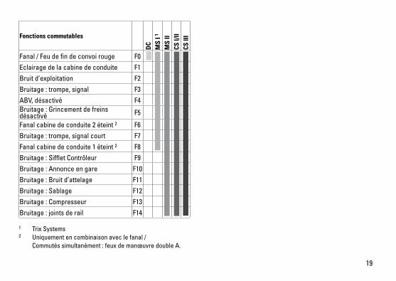
Fonctions commutables
DC
MS
I 1
MS
IICS
I/II
CS II
I
Fanal / Feu de fin de convoi rouge F0
Eclairage de la cabine de conduite F1
Bruit d’exploitation F2
Bruitage : trompe, signal F3
ABV, désactivé F4Bruitage : Grincement de freins désactivé F5
Fanal cabine de conduite 2 éteint 2 F6
Bruitage : trompe, signal court F7
Fanal cabine de conduite 1 éteint 2 F8
Bruitage : Sifflet Contrôleur F9
Bruitage : Annonce en gare F10
Bruitage : Bruit d’attelage F11
Bruitage : Sablage F12
Bruitage : Compresseur F13
Bruitage : joints de rail F14
1 Trix Systems2 Uniquement en combinaison avec le fanal / Commutés simultanément : feux de manœuvre double A.
20
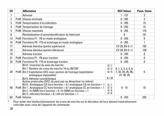
CV Affectation DCC Valeur Parm. Usine 1 Adresse 1 - 127 3 2 PoM Vitesse minimale 0 - 255 33 PoM Temporisation d‘accélération 0 - 255 154 PoM Temporisation de freinage 0 - 255 155 PoM Vitesse maximale 0 - 255 1758 Réinitialisation d’usine/identification du fabricant 8 131
13 PoM Fonctions F1 - F8 en mode analogique 0 - 255 014 PoM Fonctions F9 - F15 et éclairage en mode analogique 0 - 255 117 Adresse étendue (partie supérieure) CV29,Bit5=1 19218 Adresse étendue (partie inférieure) CV29,Bit5=1 12819 Adresse traction 0 - 255 021 PoM Fonctions F1 - F8 pour traction 0 - 255 022 PoM Fonctions F9 - F15 et éclairage traction 0 - 255 0
29 PoM
Bit 0 : Inversion du sens de marche Bit 1: Nombre de crans de marche 14 ou 28/128*Bit 2: Exploitation DCC avec section de freinage (exploitation analogique impossible) Bit 5: Adresse courte/longue
0 / 1 0 / 2 0 / 4
0 / 32
0, 1, 2, 3, 4, 5, 6, 7, 32, 34, 35, 36,
37, 38, 396
50 PoM
Autres protocoles (DCC ne peut pas se désactiver lui-même) Bit0:AnalogiqueCAhorsfonction=0/analogiqueCAenfonction=1 Bit1:AnalogiqueCChorsfonction=0/analogiqueCCenfonction=1 Bit2:fx(MM)horsfonction=0/fx(MM)enfonction=1 Bit3:mfxhorsfonction=0/mfxenfonction=1
0 / 1 0 / 2 0 / 4 0 / 8
0 - 15 15
63 PoM Volume 0 - 255 255* Pour éviter tout dysfonctionnement, les crans de marche sur le décodeur de loco doivent impérativement
coïncider avec ceux de l’appareil de commande.
21
Veiligheidsvoorschriften• Delocmagalleenmeteendaarvoorbestemdbedrijfssys-
teem gebruikt worden.• Analoogmax.15Volt=,digitaalmax.22Volt~.• Delocmagnietvanuitmeerdanéénstroomvoorziening
gelijktijdig gevoed worden.• Leesookaandachtigdeveiligheidsvoorschrifteninde
gebruiksaanwijzing van uw bedrijfssysteem. • Voorhetconventionelebedrijfmetdelocdientde
aansluitrail te worden ontstoort. Hiervoor dient men de ontstoor-set 611 655 te gebruiken. Voor het digitale bedrijf is deze ontstoor-set niet geschikt.
• OPGEPAST! Functionele scherpe kanten en punten.• Stelhetmodelnietblootaanindirectezonnestraling,
sterke temperatuurwisselingen of hoge luchtvochtigheid.• IngebouwdeLED’skomenovereenmetdelaserklasse1
volgens de norm EN 60825-1. Belangrijke aanwijzing• Degebruiksaanwijzingendeverpakkingzijneenbe-
standdeel van het product en dienen derhalve bewaard en meegeleverd te worden bij het doorgeven van het product.
• VoorreparatiesenonderdelenkuntzichtotUwTrixhandelaar wenden.
• Vrijwaringengarantieovereenkomstighetbijgevoegdegarantiebewijs.
• Afdanken:www.maerklin.com/en/imprint.html• Devolledigetoegangtotallefunctiesisalleenmogelijk
met Trix Systems, DCC of met mfx bedrijf.
• Ingebouwde,rijrichtingsafhankelijkefrontverlichtingisinhet digitaalsysteem schakelbaar.
• Minimaleteberijdenradius:360mm.
MultiprotocolbedrijfAnaloogbedrijfDe decoder kan ook op analoge modelbanen of spoortra-jecten gebruikt worden. De decoder herkent de analoge gelijkspanning (DC) automatisch en past zich aan de analoge railspanning aan. Alle functies die onder mfx of DCC voor het analoge bedrijf zijn ingesteld, worden geactiveerd (zie digitaalbedrijf).
DigitaalbedrijfDe Decoder is een multiprotocoldecoder. De decoder kan onder de volgende digitale protocollen ingezet worden: mfx, DCC. Het digitaalprotocol met de meeste mogelijkheden is het primaire digitaalprotocol. De volgorde van de digitaalproto-collen is afnemend in mogelijkheden: Prioriteit 1: mfx Prioriteit 2: DCC Prioriteit 3: DCOpmerking: Als er twee of meer digitale protocollen op de rails worden herkend, dan neemt de decoder automa-tisch het hoogwaardigste protocol over; bijv. word mfx & DCC herkend, dan wordt het mfx signaal door de decoder overgenomen. De verschillende protocollen kunnen via de parameter CV 50 gedeactiveerd worden.
22
Opmerking: let er op dat niet alle functies in alle digitaal-protocollen mogelijk zijn. Onder mfx of DCC kunnen enkele instellingen, welke in analoogbedrijf werkzaam moeten zijn, ingesteld worden.
Aanwijzingen voor digitale besturing • Hetopdejuistewijzeinstellenvandediverseparame-
ters staat beschreven in de handleiding van uw digitale Centrale.
• Hetbedrijfmettegengepooldegelijkspanningindeafrem-sectie is met de fabrieksinstelling niet mogelijk. Indien deze eigenschap wenselijk is, dan moet worden afgezien van hetconventioneelgelijkstroombedrijf(CV29/Bit2=0).
mfx-protocol
Adressering • Eenadresisnietnodig,elkedecoderheefteenéénmalig
en éénduidig kenmerk (UID).• DedecodermeldtzichvanzelfaanbijhetCentralStation
of Mobile Station met zijn UID.• Naamafdefabriek:217 014-0 DB AG
Programmering • Deeigenschappenkunnenm.b.v.hetgrafischescherm
op het Central Station resp. deels ook met het Mobile Station geprogrammeerd worden.
• Alleconfiguratievariabelen(CV)kunnenvakergelezenen geprogrammeerd worden.
• Deprogrammeringkanzowelophethoofdspooralsophet programmeerspoor gebeuren.
• Dedefault-instellingen(fabrieksinstelling)kunnenweerhersteld worden.
• Functiemapping:functieskunnenmetbehulpvanhetCentral Station 60212 (met beperking) en met het Central Station 60213/60214/60215/60216/60226 aan elke gewenste functietoets worden toegewezen (zie het helpbestand in het Central Station).
23
DCC-protocol
Adressering • Mogelijkeadressen:kort,langentractieadres• Adresbereik:
1 – 127 (kort adres, tractieadres) 1 – 10239 (lange adres)
• Elkadresishandmatigprogrammeerbaar.• KortoflangadreswordtviadeCVgekozen.• Eentoegepasttractieadresdeactiveerthetstandaardad-
res.
Programmering• Deeigenschappenvandedecoderkunnenviadeconfi-
guratie variabelen (CV) vaker gewijzigd worden.• DeCV-nummersendeCV-waardenwordendirectinge-
voerd.• DeCV’skunnenvakergelezenengeprogrammeerd
worden (programmering op het programmeerspoor).• DeCVskunnennaarwensgeprogrammeerdworden.
PoM (Programmering op het hoofdspoor) is alleen moge-lijk bij de in de CV-tabel gemerkte CV. PoM moet door uw centrale ondersteund worden (zie de gebruiksaanwijzing van uw centrale).
• Dedefault-instellingen(fabrieksinstelling)kunnenweerhersteld worden.
• 14resp.28/126rijstappeninstelbaar.• Allefunctieskunnenovereenkomstigdefunctiemapping
geschakeld worden (zie CV-beschrijving).• Voorverdereinformatie,ziedeCV-tabelDCC-protocol.
Het is aan te bevelen om het programmeren alleen op het programmeerspoor uit te voeren.
Fysieke functies
Optrek en afremvertraging• Deoptrek-enafremvertragingkunnenonafhankelijkvan
elkaar ingesteld worden. • DelogischeuitschakelfunctieABV(optrek-enafremver-
traging) kan met de functiemapping aan elke gewenste functietoets toegewezen worden.

24
Schakelbare functies
DC
MS
I 1
MS
IICS
I/II
CS II
I
Frontsein / Sluitlicht rood F0
Cabineverlichting F1
Bedrijfsgeluiden F2
Geluid: signaalhoorn F3
ABV, uit F4
Geluid: piepende remmen uit F5
Frontsein cabine 2 uit 2 F6
Geluid: signaalhoorn kort F7
Frontsein cabine 1 uit 2 F8
Geluid: conducteurfluit F9
Geluid: stationsomroep F10
Geluid: koppelingsgeluid F11
Geluid: zandstrooier F12
Geluid: compressor F13
Geluid: raillassen F14
1 Trix Systems2 Alleen in combinatie met frontlicht / Tezamen geschakeld: rangeerlicht dubbel A.
25
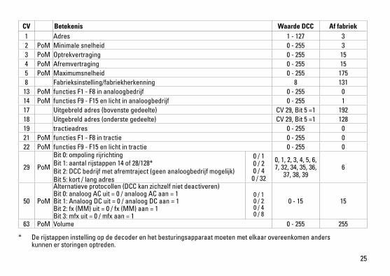
* De rijstappen instelling op de decoder en het besturingsapparaat moeten met elkaar overeenkomen anders kunnen er storingen optreden.
CV Betekenis Waarde DCC Af fabriek1 Adres 1 - 127 3 2 PoM Minimale snelheid 0 - 255 33 PoM Optrekvertraging 0 - 255 154 PoM Afremvertraging 0 - 255 155 PoM Maximumsnelheid 0 - 255 1758 Fabrieksinstelling/fabriekherkenning 8 131
13 PoM functies F1 - F8 in analoogbedrijf 0 - 255 014 PoM functies F9 - F15 en licht in analoogbedrijf 0 - 255 117 Uitgebreld adres (bovenste gedeelte) CV29,Bit5=1 19218 Uitgebreld adres (onderste gedeelte) CV29,Bit5=1 12819 tractieadres 0 - 255 021 PoM functies F1 - F8 in tractie 0 - 255 022 PoM functies F9 - F15 en licht in tractie 0 - 255 0
29 PoM
Bit 0: ompoling rijrichting Bit 1: aantal rijstappen 14 of 28/128*Bit 2: DCC bedrijf met afremtraject (geen analoogbedrijf mogelijk) Bit 5: kort / lang adres
0 / 1 0 / 2 0 / 4
0 / 32
0, 1, 2, 3, 4, 5, 6, 7, 32, 34, 35, 36,
37, 38, 396
50 PoM
Alternatieve protocollen (DCC kan zichzelf niet deactiveren) Bit0:analoogACuit=0/analoogACaan=1 Bit1:AnaloogDCuit=0/analoogDCaan=1 Bit2:fx(MM)uit=0/fx(MM)aan=1 Bit3:mfxuit=0/mfxaan=1
0 / 1 0 / 2 0 / 4 0 / 8
0 - 15 15
63 PoM Volume 0 - 255 255
26
2.
27
2.
1.
1.
1.1.
2.
3.
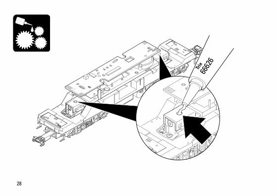
28
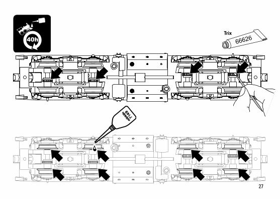
6662
6
Trix
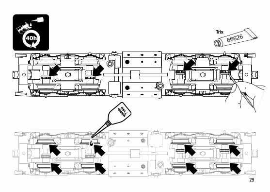
29
40hTrix
30
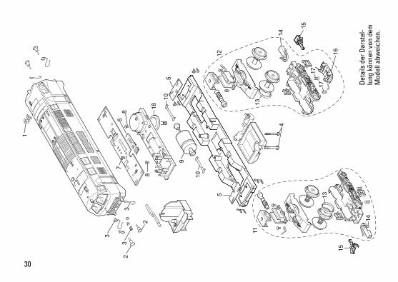
2
1
3
3
3
2
76
8
8
105
10
9
5 13
14
11
15
4
16
15
13
12
18
1717
14
Det
ails
der
Dar
stel
-lu
ng k
önne
n vo
n de
m
Mod
ell a
bwei
chen
.
31
Remarque : Certains éléments sont proposés uniquement sans livrée ou dans une livrée différente. Les pièces ne figu-rant pas dans cette liste peuvent être réparées uniquement par le service de réparation Märklin.
Opmerking: enkele delen worden alleen kleurloos of in een andere kleur aangeboden. Delen die niet in de in de lijst voorkomen, kunnen alleen via een reparatie in het Märklin-service-centrum hersteld/vervangen worden.
Nota: algunas piezas están disponibles sólo sin o con otro color. Las piezas que no figuran aquí pueden repararse únicamente en el marco de una reparación en el servicio de reparación de Märklin.
Avvertenza: Alcuni elementi vengono proposti solo senza o con differente colorazione. I pezzi che non sono qui spe-cificati possono venire riparati soltanto nel quadro di una riparazione presso il Servizio Riparazioni Märklin.
Observera: Vissa delar finns endast att tillgå från Märklin olackerade eller i en annan färgsättning. Delar som ej finns upptagna här kan endast erhållas i samband med att reparationen genomförs på Märklins egen verkstad: Märklin Reparatur-Service.
Bemærk: Nogle dele udbydes kun med eller uden anden farvesammensætning. Dele, der ikke er anført her, kan kun repareres i forbindelse med en reparation i Märklins reparationsservice.
1 Hutzen, Auspuff E197 647 2 Puffer E761 860 3 Steckt.Pufferbohle E125 572 4 Schraube E786 430 5 Stirnbeleuchtung E131 118 6 Decoder 253 467 7 Schraube E786 330 8 Schraube E786 750 9 Motor E252 284 10 Kardanwelle E104 432 11 Antriebseinheit vo. E255 832 12 Antriebseinheit hi. E255 833 13 Haftreifen 7 154 14 Kupplungsdeichsel E101 975 15 Kurzkupplung E701 630 16 Schleifer E204 535 17 Schraube E786 790 18 Lautsprecher E182 576 Bremsleitung E12 5149 00 Tritte E125 575
Hinweis: Einige Teile werden nur ohne oder mit anderer Farbgebung angeboten. Teile, die hier nicht aufgeführt sind, können nur im Rahmen einer Reparatur im Märklin-Reparatur-Service repariert werden.
Note: Several parts are offered unpainted or in another color. Parts that are not listed here can only be repaired by the Märklin repair service department.
Gebr. Märklin & Cie. GmbH Stuttgarter Straße 55 - 57 73033 Göppingen Germanywww.trix.de
253529/1216/Sc1EfÄnderungen vorbehalten
© Gebr. Märklin & Cie. GmbH
Due to different legal requirements regarding electro-magnetic compatibility, this item may be used in the USA only after separate certification for FCC com-pliance and an adjustment if necessary. Use in the USA without this certification is not permitted and absolves us of any liability. If you should want such certification to be done, please contact us – also due to the additional costs incurred for this.
www.maerklin.com/en/imprint.html

DK
S Modell der Diesellokomotive BR 217
22417

2
3
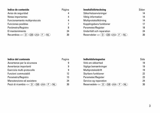
Indice de contenido PáginaAviso de seguridad 4Notas importantes 4Funcionamiento multiprotocolo 4Funciones posibles 7Parámetro/Registro 8El mantenimiento 24Recambios => D GB USA F NL 30
Indice del contenuto PaginaAvvertenze per la sicurezza 9Avvertenze importanti 9Esercizio multi-protocollo 9Funzioni commutabili 12Parametro/Registro 13Manutenzione ed assistere 24Pezzi di ricambio => D GB USA F NL 30
Innehållsförteckning SidanSäkerhetsanvisningar 14Viktig information 14Multiprotokollkörning 14Kopplingsbara funktioner 17Parameter/Register 18Underhåll och reparation 24Reservdelar => D GB USA F NL 30
Indholdsfortegnelse SideVink om sikkerhed 19Vigtige bemærkninger 19Multiprotokoldrift 19Styrbare funktioner 22Parameter/Register 23Service og reparation 24Reservedele => D GB USA F NL 30
4
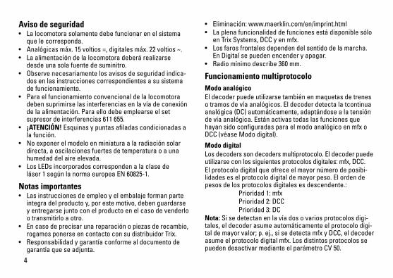
Aviso de seguridad • Lalocomotorasolamentedebefuncionarenelsistema
que le corresponda. • Analógicasmáx.15voltios=,digitalesmáx.22voltios~.• Laalimentacióndelalocomotoradeberárealizarse
desde una sola fuente de suminitro. • Observenecesariamentelosavisosdeseguridadindica-
dos en las instrucciones correspondientes a su sistema de funcionamiento.
• Paraelfuncionamientoconvencionaldelalocomotoradebensuprimirselasinterferenciasenlavíadeconexióndelaalimentación.Paraellodebeemplearseelsetsupresordeinterferencias611655.
• ¡ATENCIÓN! Esquinas y puntas afiladas condicionadas a lafunción.
• Noexponerelmodeloenminiaturaalaradiaciónsolardirecta,aoscilacionesfuertesdetemperaturaoaunahumedad del aire elevada.
• LosLEDsincorporadoscorrespondenalaclasede láser1segúnlanormaeuropeaEN60825-1.
Notas importantes • Lasinstruccionesdeempleoyelembalajeformanparteíntegradelproductoy,porestemotivo,debenguardarseyentregarsejuntoconelproductoenelcasodevenderloo transmitirlo a otro.
• Encasodeprecisarunareparaciónopiezasderecambio,rogamosponerseencontactoconsudistribuidorTrix.
• Responsabilidadygarantíaconformealdocumentodegarantíaqueseadjunta.
• Eliminación:www.maerklin.com/en/imprint.html• LaplenafuncionalidaddefuncionesestádisponiblesóloenTrixSystems,DCCyenmfx.
• Losfarosfrontalesdependendelsentidodelamarcha. En Digital se pueden encender y apagar.
• Radiomínimodescribe360mm.
Funcionamiento multiprotocoloModo analógicoEl decoder puede utilizarse también en maquetas de trenes otramosdevíaanalógicos.Eldecoderdetectalatcontinuaanalógica(DC)automáticamente,adaptándosealatensióndevíaanalógica.EstánactivastodaslasfuncionesquehayansidoconfiguradasparaelmodoanalógicoenmfxoDCC(véaseMododigital).
Modo digitalLosdecoderssondecodersmultiprotocolo.Eldecoderpuedeutilizarseconlossiguientesprotocolosdigitales:mfx,DCC.El protocolo digital que ofrece el mayor número de posibi-lidades es el protocolo digital de mayor peso. El orden de pesosdelosprotocolosdigitalesesdescendente.: Prioridad1:mfx Prioridad2:DCC Prioridad3:DCNota: Si se detectan en la vía dos o varios protocolos digi-tales,eldecoderasumeautomáticamenteelprotocolodigi-taldemayorvalor;p.ej.,sisedetectamfxyDCC,eldecoderasumeelprotocolodigitalmfx.LosdistintosprotocolossepuedendesactivarmedianteelparámetroCV50.
5
Nota: Tenga presente que no son posibles todas las funcionesentodoslosprotocolosdigitales.EnmfxyDCCpueden configurarse algunos parámetros de funciones que debentenerefectoenelmodoanalógico.
Informaciones para el funcionamiento digital • Deberáconsultarelprocedimientoexactodeconfi-guracióndelosdiversosparámetrosenelmanualdeinstrucciones de la central multitren que desee utilizar.
• Noesposibleelfuncionamientocontensióndecorrientecontinua de polaridad opuesta en el tramo de frenado en funcionamientoenmodoDCC.Sisedeseaestacaracterí-stica,deberenunciarsealfuncionamientoconvencionalconcorrientecontinua(CV29/Bit2=0).
Protocolo mfx
Direccionamiento • Noserequieredireccionamiento,recibiendocadadeco-derunaidentificaciónuniversalmenteúnicaeinequívoca(UID)
• Eldecodersedadealtaautomáticamenteenuna CentralStationoenunaMobileStationconsuUID:
• Nombredefabrica:217 014-0 DB AG
Programación• LascaracterísticaspuedenprogramarsemediantelainterfazgráficadelaCentralStationobienenpartetambién con la Mobile Station.
• EsposibleleeryprogramarmúltiplesvecestodaslasVariablesdeConfiguración(CV).
• Laprogramaciónpuederealizarsebienenlavíaprincipaloenlavíadeprogramación.
• Esposiblerestaurarlaconfiguraciónpordefecto(confi-guracióndefábrica).
• Mapeadodefunciones:lasfuncionespuedenasig-narseacualesquierateclasdefunción(véaseAyudaenlaCentralStation)conayudadelaCentralStati-on60212(conlimitaciones)yconlaCentralStation60213/60214/60215/60216/60226.
6
Protocolo DCC
Direccionamiento• Direccionesposibles:direccióncorta,direcciónlargaydireccióndetracción
• Intervalodedirecciones: 1–127(direccióncorta,direccióndetracción) 1–10239(direcciónlarga)
• Cadadirecciónpuedeprogramarsemanualmente.• LadireccióncortaolargaseseleccionamediantelasCVs.• Unadireccióndetracciónaplicadadesactivaladirecci-ónestándar.
Programación• LascaracterísticaspuedenmodificarsemúltiplesvecesmediantelasVariablesdeConfiguración(CV).
• ElnúmerodeCVylosvaloresdecadaCVseintroducendirectamente.
• LasCVspuedenleerseyprogramarsemúltiplesveces(programaciónenlavíadeprogramación).
• LasCVssepuedenprogramarlibremente.PoM(pro-gramaciónenlavíaprincipal)esposibleúnicamenteenlasvariablesCVsidentificadasenlatabladeCVs.ParapoderutilizarlaPoM,éstadebesersoportadaporsucentral(verInstruccionesdeempleodesudispositivo).
• Lasconfiguracionespordefecto(configuracionesdefábrica)puedenrestaurarse.
• Puedenconfigurarse14obien28/126nivelesdemarcha.• Todaslasfuncionespuedenmaniobrarseconformealmapeadodefunciones(véaseDescripcióndelasCVs).
• Paramásinformación,véaseTabladeCVsparaprotocoloDCC.
Pornorma,serecomiendarealizarlasprogramacionesenlavíadeprogramación.
Funciones lógicas
Retardo de aceleración/frenado• Lostiemposdeaceleraciónydefrenadosepueden
configurar por separado uno del otro. • Ladesactivaciónlógicadelafunciónderetardodeaceleración/frenadosepuedeasignaracualquiertecladefunciónmedianteelmapeadodefunciones.
7
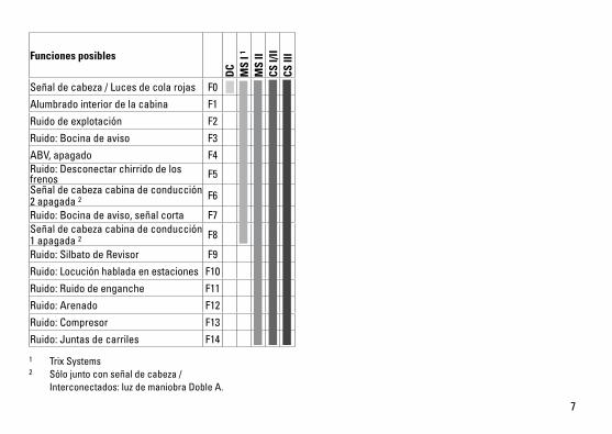
Funciones posibles
DC
MS
I 1
MS
IICS
I/II
CS II
I
Señaldecabeza/Lucesdecolarojas F0
Alumbrado interior de la cabina F1
Ruidodeexplotación F2
Ruido:Bocinadeaviso F3
ABV,apagado F4Ruido:Desconectarchirridodelosfrenos F5Señaldecabezacabinadeconducción2 apagada 2 F6
Ruido:Bocinadeaviso,señalcorta F7Señaldecabezacabinadeconducción1 apagada 2 F8
Ruido:SilbatodeRevisor F9
Ruido:Locuciónhabladaenestaciones F10
Ruido:Ruidodeenganche F11
Ruido:Arenado F12
Ruido:Compresor F13
Ruido:Juntasdecarriles F14
1 TrixSystems2 Sólojuntoconseñaldecabeza/ Interconectados:luzdemaniobraDobleA.
8
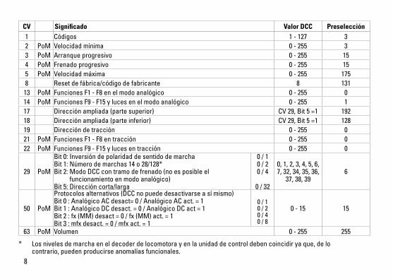
* Losnivelesdemarchaeneldecoderdelocomotorayenlaunidaddecontroldebencoincidiryaque,delo contrario,puedenproducirseanomalíasfuncionales.
CV Significado Valor DCC Preselección1 Códigos 1 - 127 3 2 PoM Velocidad mínima 0-255 33 PoM Arranque progresivo 0-255 154 PoM Frenado progresivo 0-255 155 PoM Velocidadmáxima 0-255 1758 Resetdefábrica/códigodefabricante 8 131
13 PoM FuncionesF1-F8enelmodoanalógico 0-255 014 PoM FuncionesF9-F15ylucesenelmodoanalógico 0-255 117 Direcciónampliada(partesuperior) CV29,Bit5=1 19218 Direcciónampliada(parteinferior) CV29,Bit5=1 12819 Direccióndetracción 0-255 021 PoM FuncionesF1-F8entracción 0-255 022 PoM FuncionesF9-F15ylucesentracción 0-255 0
29 PoM
Bit0:Inversióndepolaridaddesentidodemarcha Bit1:Númerodemarchas14o28/128* Bit2:ModoDCCcontramodefrenado(noesposibleel funcionamientoenmodoanalógico) Bit5:Direccióncorta/larga
0 / 1 0 / 2 0 / 4
0 / 32
0,1,2,3,4,5,6,7,32,34,35,36,37,38,39
6
50 PoM
Protocolosalternativos(DCCnopuededesactivarseasímismo) Bit0:AnalógicoACdesact=0/AnalógicoACact.=1 Bit1:AnalógicoDCdesact.=0/AnalógicoDCact=1 Bit2:fx(MM)desact=0/fx(MM)act.=1 Bit3:mfxdesact.=0/mfxact.=1
0 / 1 0 / 2 0 / 4 0 / 8
0-15 15
63 PoM Volumen 0-255 255
9
Avvertenze per la sicurezza • Talelocomotivadevevenireimpiegatasoltantoconun
sistema di esercizio prestabilito a questo scopo.• Analogicomax.15Volt=,digitalemax.22Volt~.• Lalocomotivanondevevenirealimentatanellostesso
tempo con più di una sorgente di potenza.• Vogliateprestareassolutamenteattenzionealleavverten-
ze di sicurezza nelle istruzioni di impiego per il Vostro sistema di funzionamento.
• Perilfunzionamentotradizionaledellalocomotivailbinario di alimentazione deve essere protetto dai disturbi. A tale scopo si deve impiegare il corredo antidisturbi 611655.Talecorredoantidisturbinonèadattoperilfunzionamento Digital.
• AVVERTENZA! Per motivi funzionali i bordi e le punte sono spigolosi.
• Nonesponetetalemodelloadalcunirraggiamentosolarediretto,afortiescursioniditemperaturaoppureaelevataumidità dell’aria.
• ILEDincorporaticorrispondonoallacategoriadilaser1secondolaNormaEN60825-1.
Avvertenze importanti• Leistruzionidiimpiegoel’imballaggiocostituisconoun
componente sostanziale del prodotto e devono pertanto venire conservati nonché consegnati insieme in caso di ulteriore cessione del prodotto.
• Perleriparazioniolepartidiricambio,contrattareilrivenditoreTrix.
• Prestazionidigaranziaegaranziainconformitàall’acclu-so certificato di garanzia.
• Smaltimento:www.maerklin.com/en/imprint.html• LacompletadotazionedifunzionièdisponibilesoltantosottoTrixSystems,DCCesottomfx.
• IIluminazioneditestaincorporata,dipendentedalladire-zionedimarcia.CommutabilenelfunzionamentoDigital.
• Raggiominimopercorribile360mm.
Esercizio multi-protocolloEsercizio analogicoTale Decoder può venire fatto funzionare anche su impianti o sezionidibinarioanalogiche.IlDecoderriconosceautomati-camentelatensioneanalogica(DC)esiadeguaallatensioneanalogica del binario. Vi sono attive tutte le funzioni che erano stateimpostateperl’esercizioanalogicosottomfxoppureDCC(sivedaesercizioDigital).
Esercizio DigitalIDecodersonoDecodermulti-protocollo.IlDecoderpuòvenireimpiegatosottoiseguentiprotocolliDigital:mfx,DCC.IlprotocolloDigitalconilmaggiornumerodipossibilitàèilprotocollodigitaledimassimovalore.LasequenzadeiprotocolliDigital,convaloridecrescenti,è: Priorità1:mfx Priorità2:DCC Priorità3:DCAvvertenza: Qualora sul binario vengano riconosciuti due o piùprotocollidigitali,ilDecoderassumeautomaticamenteil protocollo digitale con il valore più elevato; ad es. se vienericonosciutomfx&DCC,vieneassuntodalDecoderilprotocollodigitalemfx.IsingoliprotocollipossonoveniredisattivatimedianteilparametroCV50.
10
Avvertenza: Prestate attenzione al fatto che non tutte le funzionisonopossibiliintuttiiprotocolliDigital.SottomfxeDCCpossonovenireeseguitealcuneimpostazionidifunzio-ni,lequalisarannoefficacinell’esercizioanalogico.
Istruzioni per la funzione digitale • L’esattoprocedimentoperl’impostazionedeidifferenti
parametri siete pregati di ricavarlo dalle istruzioni di servizio della Vostra centrale per molti treni.
• Unfunzionamentocontensionecontinuadipolaritàin-vertitanellasezionedifrenatura,incasodiesercizioconDCC,nonèpossibile.Sesidesideraquestacaratteristica,si deve in tal caso rinunciare al funzionamento tradiziona-leincorrentecontinua(CV29/Bit2=0).
Protocollo mfx
Indirizzamento• Nessunindirizzonecessario,ciascunDecoderriceveunasuaidentificazioneirripetibileeunivoca(UID).
• IlDecodersiannunciaautomaticamenteadunaCentralStationoppureMobileStationconilsuoUID.
• Nomedifabrica:217 014-0 DB AG
Programmazione• LecaratteristichepossonovenireprogrammatetramitelasuperficiegraficadellaCentralStationorispettivamentein parte anche con la Mobile Station.
• TutteleVariabilidiConfigurazione(CV)possonovenireripetutamente lette e programmate.
• Taleprogrammazionepuòavveniresuibinariprincipalioppure sul binario di programmazione.
• Leimpostazionididefault(impostazionidifabbrica)possono venire nuovamente riprodotte.
• Mappaturadellefunzioni:conl’ausiliodellaCentralStation60212(limitatamente)econlaCentralStation60213/60214/60215/60216/60226lefunzionipossonovenireassegnateadeitastifunzioneapiacere(sivedanoleguidediaiutonellaCentralStation).
11
Protocollo DCC
Indirizzamento• Possibiliindirizzi:brevi,lunghieindirizzipertrazioni
multiple• Campodegliindirizzi: 1–127(indirizzibrevi,indirizzipertrazionimultiple) 1–10239(indirizzilunghi)
• Ciascunindirizzoèprogrammabilemanualmente.• L’indirizzobreveolungovieneselezionatotramiteleCV.• Unindirizzodiunitàditrazioneutilizzatodisattival’indiriz-
zo standard.
Programmazione• Lecaratteristichepossonovenireripetutamentemodifi-catetramiteleVariabilidiConfigurazione(CV).
• IlnumerodellaCVedivaloridellaCVvengonointrodottidirettamente.
• LeCVpossonovenireripetutamenteletteeprogrammate(Programmazionesulbinariodiprogrammazione).
• LeCVpossonovenireprogrammatecomesivuole.LaPoM(programmazionesulbinarioprincipale)èpossibilesoltantonelcasodelleCVcontrassegnatenellatabelladelleCV.LaPoMdeveveniresupportatadallaVostraUnitàCentrale(sivedanoleistruzionidiazionamentodelVostroapparato).
• Leimpostazionididefault(impostazionidifabbrica)possono venire nuovamente riprodotte.
• 14 o rispettivamente 26/126 gradazioni di marcia impostabili.
• Tuttelefunzionipossonovenirecommutateinmodorispondenteallamappaturadellefunzioni(sivedaladescrizionedelleCV).
• Perulterioriinformazioni,sivedalatabelladelleCVnelprotocolloDCC.
È consigliabile intraprendere le programmazioni essenzial-mente sul binario di programmazione.
Funzioni logiche
Ritardo di avviamento/frenatura • Laduratadiaccelerazioneedifrenaturapossonovenire
impostate separatamente una dall’altra. • LadisattivazionelogicaditalefunzioneABVpuòvenire
assegnata a piacere a ciascun tasto di funzione mediante la mappatura delle funzioni.
12
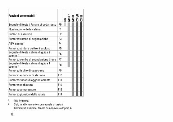
Funzioni commutabili
DC
MS
I 1
MS
IICS
I/II
CS II
I
Segnale di testa / Fanale di coda rosso F0
Illuminazionedellacabina F1
Rumori di esercizio F2
Rumore:trombadisegnalazione F3
ABV,spente F4
Rumore:stridoredeifreniescluso F5Segnale di testa cabina di guida 2 spento 2 F6
Rumore:trombadisegnalazionebreve F7Segnale di testa cabina di guida 1 spento 2 F8
Rumore:fischiodicapotreno F9
Rumore:annunciodistazione F10
Rumore:rumoridiagganciamento F11
Rumore:sabbiatura F12
Rumore:compressore F13
Rumore:giunzionidellerotaie F14
1 TrixSystems2 Solo in abbinamento con segnale di testa / Commutatiassieme:fanaledimanovraadoppiaA.
13
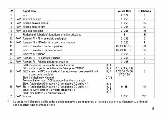
CV Significato Valore DCC Di fabbrica1 Indirizzo 1 - 127 3 2 PoM Velocità minima 0-255 33 PoM Ritardo di avviamento 0-255 154 PoM Ritardo di frenatura 0-255 155 PoM Velocità massima 0-255 1758 Ripristinodifabbrica/Identificazionediproduzione 8 131
13 PoM Funzioni F1 - F8 in esercizio analogico 0-255 014 PoM FunzioniF9-F15eluciinesercizioanalogico 0-255 117 Indirizzoampliato(partesuperiore) CV29,Bit5=1 19218 Indirizzoampliato(parteinferiore) CV29,Bit5=1 12819 Indirizzoditrazione 0-255 021 PoM Funzioni F1 - F8 durante trazione 0-255 022 PoM FunzioniF9-F15elucidurantetrazione 0-255 0
29 PoM
Bit0:inversionepolaritàdelsensodimarcia Bit1:numerogradazionidimarcia14oppure28/128* Bit2:esercizioDCCcontrattadifrenatura(nessunapossibilitàdi esercizioanalogico) Bit5:indirizzibrevi/lunghi
0 / 1 0 / 2 0 / 4
0 / 32
0,1,2,3,4,5,6,7,32,34,35,36,37,38,39
6
50 PoM
Protocollialternativi(DCCnonpuòdisattivarsidasolo) Bit0:AnalogicoACinattivo=0/AnalogicoACattivo=1 Bit1:AnalogicoDCinattivo=0/AnalogicoDCattivo=1 Bit2:fx(MM)inattivo=0/fx(MM)attivo=1 Bit3:mfxinattivo=0/mfxattivo=1
0 / 1 0 / 2 0 / 4 0 / 8
0-15 15
63 PoM Volume 0-255 255
* LegradazionidimarciasulDecoderdellalocomotivaesulregolatoredimarciasidevonocorrispondere,altrimenti sono possibili funzionamenti erronei.
14
Säkerhetsanvisningar • Loketfårendastkörasmeddärtillavsettdriftsystem.• Analogmax.15Volt=,digitalmax.22Volt~.• Loketfårintesamtidigtförsörjasavmeränenkraftkälla.• Beaktaalltidsäkerhetsanvisningarnaibruksanvisningen
som hör till respektive driftsystemet. • Närdenmotorförseddalokdelenskakörasmedkon-
ventionell drift måste anlutningsskenan vara avstörd. Tilldettaanvändermananslutningsgarnityr611655medavstörning och överbelastningsskydd. Avstörningsskyd-det får inte användas vid digital körning.
• VARNING! Funktionsbetingade vassa kanter och spetsar.• Modellenfårinteutsättasfördirektsolljus,häftigatem-peraturväxlingarellerhögluftfuktighet.
• InbyggdaLED(lysdioder)motsvararlaser-klass1enligtEnnorm60825-1.
Viktig information• Bruksanvisningenochförpackningenärendelavproduktenochmåstedärförsparasochalltidmedföljaprodukten.
• KontaktadinTrix-handlareförreparationerellerreserv-delar.
• Garantivillkorframgåravbifogadegarantibevis.• Hanteringsomavfall:www.maerklin.com/en/imprint.html• Fullständigtfunktionsomfångerhållsendastvidanvänd-ningavTrixSystems,DCCellermfx.
• Körriktningsberoendefrontbelysning. Kan kopplas in vid digital drift.
• Kanköraspåenminstaradieav360mm.
MultiprotokollkörningAnalog körningDekodern kan även användas vid körning på analoga anläg-gningar och spåravsnitt. Dekodern känner automatiskt igen ochgodtaranalogkörström,bådeväxelströmochlikström(AC/DC).AllamfxellerDCCfunktionerinställdaföranalogdriftäraktiverade.(v.g.se:Digitalkörning).
Digital körningDecoder är en multiprotokolldekoder. Dekodern kan använ-dastillsammansmedföljandedigital-protokoll:mfx,Dcc,.Digital-protokollet med flest funktioner är högst prioriterat. Digital-protokolleninordnasifallandeordningsomföljer: Prioritet1:mfx Prioritet2:DCC Prioritet3:fx(DC)Observera: Omtvåellerfleradigital-protokollanvändsviaspåret,såanvänderdekodernautomatisktdethögvärdi-gasteprotokollet.Användst.ex.mfx&DCC,såkommerde-kodernattanvändamfx-digital-protokollet.EnstakaprotokollkanavaktiverasmedhjälpavCV50.Observera: Tänk på att inte alla funktioner kan användas/aktiverasialladigital-protokoll.MedmfxochDCCkanvissafunktionsinställningar göras för att funktionerna ska vara aktiva vid analog körning.
15
Anvisningar för digital drift • Detaljeradeanvisningarförattställainolikaparametrar
finns i bruksanvisningen till Er digitala flertågs-körkon-troll.
• VidDCC-driftkanmaninteköramedtvåpoliglikspänningpå ett bromsavsnitt. Önskar man ändå genomföra en sådankörning,såmåstemanförlitasigpåkonventionelllikströmsdrift(CV29/Bit2=0).
mfx-protokoll
Adressering • Ingenadressbehövs,varjedekoderharenheltegenochentydigadress(UID).
• DekodernanmälersejautomatiskttillCentralStationochMobileStationviasinUID.
• Namnfrantillverkaren:217 014-0 DB AG
Programmering• EgenskapernakanprogrammerasviaCentralStations
pekskärm och även till vissa delar med Mobile Station. • Såkanävenallakonfigurations-variabler(CV)läsasin
och programmeras.• Programmeringenkangörasantingendirektpåanlägg-
ningens spår eller på programmeringsspåret. • Default-inställningarna(fabrikensinställningar)kan
återskapas.• Mappningavfunktioner:FunktionerkanmedhjälpavCentralStation60212(ivissutsträckning)ochmed CentralStation60213/60214/60215/60216/60226 kopplas till önskadefunktionsknappar(V.g.semerinformationiCentralStation).
16
DCC-protokoll
Adressering• Möjligaadresser:Korta,långaochmultippelkopplings-
adresser• Adressområde: 1–127(kortaadresser,multippelkopplings-adresser) 1–10239(långaadresser)
• Varjeenskildadresskanprogrammerasmanuellt.• KortaellerlångaadresserväljsviaCVn.• Envaldmultippelkopplingsadressavaktiverarstandard-
adresserna.
Programmering• Egenskapernakanändrasfleragångerviakonfigura-tions-variablerna(CV).
• CV-nummerochCV-värdenangesdirekt.• AllaCVnkanläsasochprogrammerasfleragånger(Programmeringgörspåprogrammeringsspåret).
• AllaCvnkanprogrammeras.PoM(Programmeringpåhuvudspåret)kanendastgenomförasmediCV-tabellenmarkeradeCvn.DincentralenhetmåstehastödförPoM(sebruksanvisningensommedföljercentralenheten).
• Defaultinställningar(fabriksinställningar)kanåterskapas.• 14upptill28/126körstegkanställasin.• Samtligafunktionerkankopplasinochmanövrerasenligtfunktions-mappningen.(V.g.seCV-beskrivningen.)
• Förytterligareinformation:V.g.seCV-tabellerDCC-proto-koll.
Vi rekommenderar att endast genomföra programmeringar på programmerings-spåret.
Logiska funktioner
Accelerations-/bromsfördröjning• Accelerations-ochinbromsningstiderkanställasin
separat.• DenlogiskafunktionsavstängningenABVkanvia
funktionsmappning bli tilldelad och styras från önskad funktionsknapp.
17
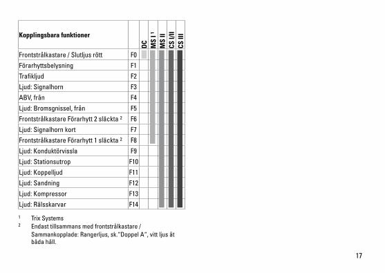
Kopplingsbara funktioner
DC
MS
I 1
MS
IICS
I/II
CS II
I
Frontstrålkastare/Slutljusrött F0
Förarhyttsbelysning F1
Trafikljud F2
Ljud:Signalhorn F3
ABV,från F4
Ljud:Bromsgnissel,från F5
Frontstrålkastare Förarhytt 2 släckta 2 F6
Ljud:Signalhornkort F7
Frontstrålkastare Förarhytt 1 släckta 2 F8
Ljud:Konduktörvissla F9
Ljud:Stationsutrop F10
Ljud:Koppelljud F11
Ljud:Sandning F12
Ljud:Kompressor F13
Ljud:Rälsskarvar F14
1 TrixSystems2 Endast tillsammans med frontstrålkastare / Sammankopplade:Rangerljus,sk.“DoppelA“,vittljusåt båda håll.
18
* Lok-dekodernskörstegochkörkontrollenskörstegmåstestämmaöverens,annarskanfelbetr.funktionernauppstå.
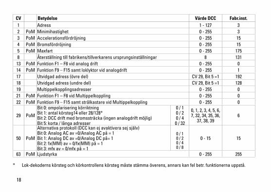
CV Betydelse Värde DCC Fabr.inst.1 Adress 1 - 127 3 2 PoM Minimihastighet 0-255 33 PoM Accelerationsfördröjning 0-255 154 PoM Bromsfördröjning 0-255 155 PoM Maxfart 0-255 1758 Återställning till fabrikens/tillverkarens ursprungsinställningar 8 131
13 PoM Funktion F1 – F8 vid analog drift 0-255 014 PoM FunktionF9–F15samtloklyktorvidanalogdrift 0-255 117 Utvidgadadress(övredel) CV29,Bit5=1 19218 Utvidgadadress(undredel) CV29,Bit5=1 12819 Multippelkopplingsadresser 0-255 021 PoM Funktion F1 – F8 vid Multippelkoppling 0-255 022 PoM FunktionF9–F15samtstrålkastarevidMultippelkoppling 0-255 0
29 PoM
Bit0:ompolariseringkörriktning Bit1:antalkörsteg14eller28/128* Bit2:DCCdriftmedbromssträcka(ingenanalogdriftmöjlig) Bit5:korta/långaadresser
0 / 1 0 / 2 0 / 4
0 / 32
0,1,2,3,4,5,6,7,32,34,35,36,37,38,39
6
50 PoM
Alternativaprotokoll(DCCkanejavaktiverasejsjälv) Bit0:AnalogACav=0/AnalogACpå=1 Bit1:AnalogDCav=0/AnalogDCpå=1 Bit2:fx(MM)av=0/fx(MM)på=1 Bit3:mfxav=0/mfxpå=1
0 / 1 0 / 2 0 / 4 0 / 8
0-15 15
63 PoM Ljudstyrka 0-255 255
19
Vink om sikkerhed• Lokomotivetmåkunanvendesmedetdriftssystem,derer
beregnet dertil. • Analogmax.15Volt=,digitalmax.22Volt~.• Lokomotivetmåikkeforsynesframereendénstrømkilde
ad gangen.• Værunderalleomstændighederopmærksompådevinkomsikkerhed,somfindesibrugsanvisningenforDeresdriftssystem.
• Vedkonventioneldriftaflokomotivetskaltilslutningssporetstøjdæmpes.Dertilskalanvendesstøjdæmpningssættet611655.Støjdæmpningssætteterikkeegnettildigitaldrift.
• ADVARSEL! Skarpe kanter og spidser pga. funktionen.• Modellenmåikkeudsættesfordirektesollys,storetemperaturudsvingellerhøjluftfugtighed.
• Deindbyggedelysdiodersvarertillaserklasse1ihenholdtilnormenEN60825-1.
Vigtige bemærkninger• Betjeningsvejledningogemballagehørertilproduktetogskalderforgemmesogmedfølge,hvisproduktetgivesvidere til andre.
• AngåendereparationerellerreservedelebedesDehenvendeDemtilDeresTrix-forhandler.
• Garantiifølgevedlagtegarantibevis.• Bortskafning:www.maerklin.com/en/imprint.html• DetkomplettefunktionsomfangerkuntilrådighedunderTrixSystems,DCCogundermfx.
• Innebygd,kjøreretningsavhengigfrontlys. Kan tændes og slukkes til digitaldrift.
• Farbarmindsteradius360mm.
Multiprotokoldrift AnalogdriftDekoderen kan også benyttes på analoge anlæg eller sporafsnit. Dekoderen genkender automatisk den analoge veksel(DC)ogtilpassersigdenanalogejævnstrøm.Allefunktioner,somindstilledestilanalogdriftundermfxellerDCC,eraktive(sedigitaldrift).
DigitaldriftmSD SoundDecodere er multiprotokoldekodere. Dekoderen kananvendesvedfølgendedigital-protokoller:mfx,DCC.Digital-protokollenmedflestmulighedererdenhøjestran-gerendedigital-protokol.Digital-protokollernesrækkefølgeermedfaldendeværdifølgende: Prioritet1:mfx Prioritet2:DCC Prioritet3:DCBemærk:Hvisdergenkendestoellerfleredigitalproto-kollerpåskinnen,overtagerdekoderenautomatiskdendigitalprotokolmeddenhøjesteværdi;hvismfx&DCCf.eks.genkendes,overtagerdekoderenmfx-digitalprotokollen.EnkelteprotokollerkandeaktiveresviaparameterCV50.Bemærk:Væropmærksompå,atikkeallefunktionerermuligeialledigital-protokoller.VedmfxogDCCkanderforetagesnogleindstillingeraffunktioner,somskalhaveeffekt ved analogdrift.
20
Henvisninger til digitaldrift • Dennøjagtigefremgangsmådetilindstillingafdeforskel-ligeparametrefindesibetjeningsvejledningentilDeresflertogs-central.
• DetervedDCC-driftikkemuligtatanvendedriftmedmodpoletjævnspændingibremseafsnittet.Hvisdenneegenskabønskes,mådergivesafkaldpådenkonventio-nellejævnstrømsdrift(CV29/Bit2=0).
mfx-protokol
Adressering• Ingenadressepåkrævet,hverdekodertildelesenunikogentydigidentitet(UID).
• DekoderentilmeldersigautomatiskencentralstationellermobilestationmedsinUID.
• Navnabfabrik:217 014-0 DB AG
Programmering• Egenskabernekanprogrammeresviacentralstations
grafiske overflade hhv. til dels også med mobile station.• Alleconfigurationvariable(CV)kanaflæsesogprogram-
meres gentagne gange.• Programmeringenkanentenskepåhoved-ellerpro-
grammeringssporet.• Defaultindstillingerne(fabriksindstillinger)kangenindstilles.• Funktionsmapping:Funktionerkanvedhjælpafcentralstation60212(begrænset)ogmedcentralstation60213/60214/60215/60216/60226tilordnesvilkårligefunkti-onstaster(Sehjælptilcentralstation).
21
DCC-protokol
Adressering • Muligeadresser:Korte,langeogtraktionsadresse• Adresseområde: 1–127(kortadresse,traktionsadresse) 1–10239(langadresse)
• Hveradressekanprogrammeresmanuelt.• KortellerlangadressevælgesviaCV‘erne.• Enanvendttraktionsadressedeaktivererstandard-adres-
sen.
Programmering• Egenskabernekanændresgentagnegangeviaconfigu-rationvariablerne(CV).
• CV-nummeretogCV-værdierneindgivesdirekte.• CV’ernekanlæsesogprogrammeresgentagegange(programmeringpåprogrammeringssporet).
• CVernekanprogrammeresefterønske.PoM(Program-meringpåhovedskinnen)erkunmuligfordenmarkeredeCViCT-tabellen.PoMskalunderstøttesafcentralen(seapparatetsbetjeningsvejledning).
• Defaultindstillingerne(fabriksindstillinger)kangenindstil-les.
• 14hhv.28/126kørselstrinkanindstilles.• Allefunktionerkanstyresjævnførfunktionsmapping(seCV-beskrivelse).
• Yderligereoplysninger,seCV-tabellenDCC-protokol.Det anbefales principielt at foretage programmeringerne på programmeringssporet.
Logiske funktioner
Opstart-/bremseforsinkelse• Accelerations-ogbremsetidenkanindstillesuafhængigt
af hinanden. • DenlogiskefunktionsafbrydningABVkanindstillespåen
vilkårlig knap via funktionsmapping.
22
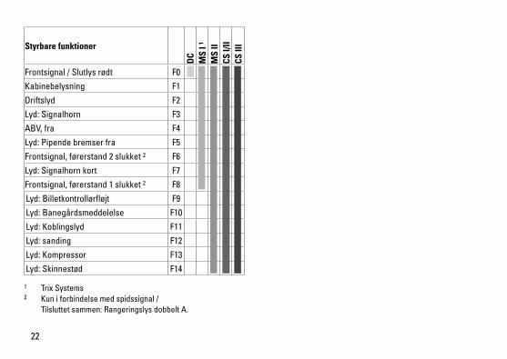
Styrbare funktioner
DC
MS
I 1
MS
IICS
I/II
CS II
I
Frontsignal/Slutlysrødt F0
Kabinebelysning F1
Driftslyd F2
Lyd:Signalhorn F3
ABV,fra F4
Lyd:Pipendebremserfra F5
Frontsignal,førerstand2slukket2 F6
Lyd:Signalhornkort F7
Frontsignal,førerstand1slukket2 F8
Lyd:Billetkontrollørfløjt F9
Lyd:Banegårdsmeddelelse F10
Lyd:Koblingslyd F11
Lyd:sanding F12
Lyd:Kompressor F13
Lyd:Skinnestød F14
1 TrixSystems2 Kun i forbindelse med spidssignal / Tilsluttetsammen:RangeringslysdobbeltA.
23
* Indstillingernepålokomotivetsdekoderogpåstyreapparatetskalstemmeoverens,dafejlfunktionellersermulig.
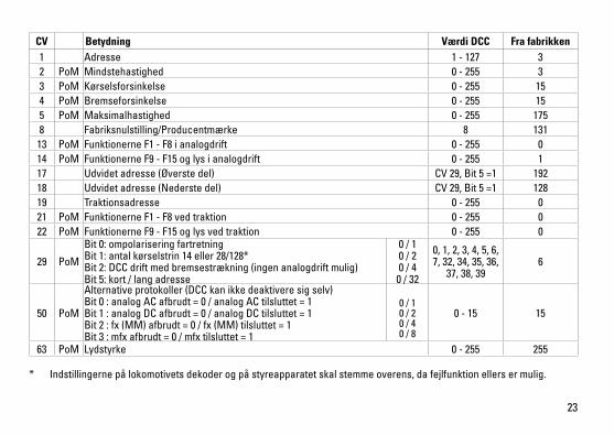
CV Betydning Værdi DCC Fra fabrikken1 Adresse 1 - 127 3 2 PoM Mindstehastighed 0-255 33 PoM Kørselsforsinkelse 0-255 154 PoM Bremseforsinkelse 0-255 155 PoM Maksimalhastighed 0-255 1758 Fabriksnulstilling/Producentmærke 8 131
13 PoM Funktionerne F1 - F8 i analogdrift 0-255 014 PoM FunktionerneF9-F15oglysianalogdrift 0-255 117 Udvidetadresse(Øverstedel) CV29,Bit5=1 19218 Udvidetadresse(Nederstedel) CV29,Bit5=1 12819 Traktionsadresse 0-255 021 PoM Funktionerne F1 - F8 ved traktion 0-255 022 PoM FunktionerneF9-F15oglysvedtraktion 0-255 0
29 PoM
Bit0:ompolariseringfartretning Bit1:antalkørselstrin14eller28/128* Bit2:DCCdriftmedbremsestrækning(ingenanalogdriftmulig) Bit5:kort/langadresse
0 / 1 0 / 2 0 / 4
0 / 32
0,1,2,3,4,5,6,7,32,34,35,36,37,38,39
6
50 PoM
Alternativeprotokoller(DCCkanikkedeaktiveresigselv) Bit0:analogACafbrudt=0/analogACtilsluttet=1 Bit1:analogDCafbrudt=0/analogDCtilsluttet=1 Bit2:fx(MM)afbrudt=0/fx(MM)tilsluttet=1 Bit3:mfxafbrudt=0/mfxtilsluttet=1
0 / 1 0 / 2 0 / 4 0 / 8
0-15 15
63 PoM Lydstyrke 0-255 255

24
2.

25
2.
1.
1.
1.1.
2.
3.

26
6662
6
Trix
27
40hTrix

Gebr.Märklin&Cie.GmbHStuttgarterStraße55-5773033GöppingenGermanywww.trix.de
253531/1216/Sc1EfÄnderungen vorbehalten
©Gebr.Märklin&Cie.GmbHwww.maerklin.com/en/imprint.html
Duetodifferentlegalrequirementsregardingelectro-magneticcompatibility,thisitemmaybeusedintheUSAonlyafterseparatecertificationforFCCcom-plianceandanadjustmentifnecessary.UseintheUSAwithoutthiscertificationisnotpermittedandabsolvesusofanyliability.Ifyoushouldwantsuchcertificationtobedone,pleasecontactus–also due to the additional costs incurred for this.


![FROST/DEICING SALT RESISTANCE OF ... - uni-stuttgart.de · essais de gel en présence de sels de déverglaçage ont été réalisés sur des éprou- ... [10] which is partly taken](https://img.pdfslide.org/doc/110x75/5c6658eb09d3f2d0218c2722/frostdeicing-salt-resistance-of-uni-essais-de-gel-en-presence-de-sels.jpg)