Embed Size (px)
Citation preview
Modell der Elektrolokomotive BR 120.1
22686F D GB USA NL

2
3
Inhaltsverzeichnis: SeiteInformationen zum Vorbild 4Sicherheitshinweise 6Wichtige Hinweise 6Multiprotokollbetrieb 6Schaltbare Funktionen 9Parameter/Register 10Wartung und Instandhaltung 26Ersatzteile 30
Table of Contents: Page Information about the prototype 4Safety Notes 11Important Notes 11Multi-Protocol Operation 11Controllable Functions 14Parameter/Register 15Service and maintenance 26Spare Parts 30
Sommaire : PageInformations concernant la locomotive réelle 5Remarques importantes sur la sécurité 16Information importante 16Mode multiprotocole 16Fonctions commutables 19Paramètre/Registre 20Entretien et maintien 26Pièces de rechange 30
Inhoudsopgave: PaginaInformatie van het voorbeeld 5Veiligheidsvoorschriften 21Belangrijke aanwijzing 21Multiprotocolbedrijf 21Schakelbare functies 24Parameter/Register 25Onderhoud en handhaving 26Onderdelen 30
4
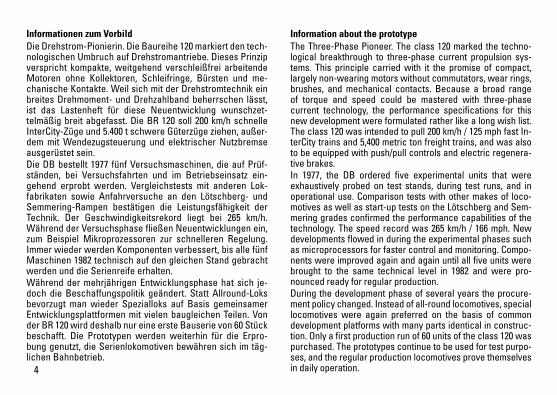
Informationen zum Vorbild Die Drehstrom-Pionierin. Die Baureihe 120 markiert den tech-nologischen Umbruch auf Drehstromantriebe. Dieses Prinzip verspricht kompakte, weitgehend verschleißfrei arbeitende Motoren ohne Kollektoren, Schleifringe, Bürsten und me-chanische Kontakte. Weil sich mit der Drehstromtechnik ein breites Drehmoment- und Drehzahlband beherrschen lässt, ist das Lastenheft für diese Neuentwicklung wunschzet-telmäßig breit abgefasst. Die BR 120 soll 200 km/h schnelle InterCity-Züge und 5.400 t schwere Güterzüge ziehen, außer-dem mit Wendezugsteuerung und elektrischer Nutzbremse ausgerüstet sein. Die DB bestellt 1977 fünf Versuchsmaschinen, die auf Prüf-ständen, bei Versuchsfahrten und im Betriebseinsatz ein-gehend erprobt werden. Vergleichstests mit anderen Lok-fabrikaten sowie Anfahrversuche an den Lötschberg- und Semmering-Rampen bestätigen die Leistungsfähigkeit der Technik. Der Geschwindigkeitsrekord liegt bei 265 km/h. Während der Versuchsphase fließen Neuentwicklungen ein, zum Beispiel Mikroprozessoren zur schnelleren Regelung. Immer wieder werden Komponenten verbessert, bis alle fünf Maschinen 1982 technisch auf den gleichen Stand gebracht werden und die Serienreife erhalten. Während der mehrjährigen Entwicklungsphase hat sich je-doch die Beschaffungspolitik geändert. Statt Allround-Loks bevorzugt man wieder Spezialloks auf Basis gemeinsamer Entwicklungsplattformen mit vielen baugleichen Teilen. Von der BR 120 wird deshalb nur eine erste Bauserie von 60 Stück beschafft. Die Prototypen werden weiterhin für die Erpro-bung genutzt, die Serienlokomotiven bewähren sich im täg-lichen Bahnbetrieb.
Information about the prototypeThe Three-Phase Pioneer. The class 120 marked the techno-logical breakthrough to three-phase current propulsion sys-tems. This principle carried with it the promise of compact, largely non-wearing motors without commutators, wear rings, brushes, and mechanical contacts. Because a broad range of torque and speed could be mastered with three-phase current technology, the performance specifications for this new development were formulated rather like a long wish list. The class 120 was intended to pull 200 km/h / 125 mph fast In-terCity trains and 5,400 metric ton freight trains, and was also to be equipped with push/pull controls and electric regenera-tive brakes. In 1977, the DB ordered five experimental units that were exhaustively probed on test stands, during test runs, and in operational use. Comparison tests with other makes of loco-motives as well as start-up tests on the Lötschberg and Sem-mering grades confirmed the performance capabilities of the technology. The speed record was 265 km/h / 166 mph. New developments flowed in during the experimental phases such as microprocessors for faster control and monitoring. Compo-nents were improved again and again until all five units were brought to the same technical level in 1982 and were pro-nounced ready for regular production. During the development phase of several years the procure-ment policy changed. Instead of all-round locomotives, special locomotives were again preferred on the basis of common development platforms with many parts identical in construc-tion. Only a first production run of 60 units of the class 120 was purchased. The prototypes continue to be used for test purpo-ses, and the regular production locomotives prove themselves in daily operation.
5
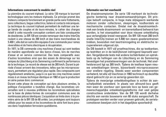
Informations concernant le modèle réel La pionnière du courant triphasé. La série 120 marque le tournant technologique vers les moteurs triphasés. Ce principe promet des moteurs compacts fonctionnant en grande partie sans frottements, sans collecteurs, bague collectrice, balais et contacts mécaniques. La technique du courant triphasé permettant de maîtriser une lar-ge bande de couples et de tours-minutes, le cahier des charges relatif à cette nouvelle conception contient une liste conséquente de desiderata. La BR 120 est censée remorquer des trains InterCity roulant à une vitesse de 200 km/h et des trains marchandises de 5.400 t ; elle doit en outre être équipée d’une commande pour rames réversibles et de freins électriques à récupération. En 1977, la DB commande cinq machines d’essai qui sont testées de manière approfondie sur des bancs d’essai, lors de marches d’essai et en service commercial. Des tests comparatifs avec d’autres locomotives ainsi que des essais de démarrage sur les rampes du Lötschberg et du Semmering confirment la performance de la technique. Le record de vitesse est de 265 km/h. Durant la pé-riode d’essai arrivent des innovations, telles que les microproces-seurs, permettant une régulation plus rapide. Des composants sont régulièrement améliorés, jusqu’à ce que les cinq machines soient mises à un niveau technique identique en 1982 et que la production en série puisse donc commencer. Durant cette phase de conception qui dura plusieurs années, la politique d’acquisition a toutefois changé. Aux locomotives uni-verselles sont à nouveau préférées les locomotives spécialisées sur la base de plates-formes de conception communes avec de nombreuses pièces identiques. L’acquisition se limite donc à la pre-mière série de la BR 120 de 60 unités. Les prototypes sont toujours utilisés pour les essais et les locomotives de série font leurs preu-ves dans l’exploitation ferroviaire quotidienne.
Informatie van het voorbeeldDe draaistroompionier. De serie 120 markeert de technolo-gische kentering naar draaistroomaandrijvingen. Dit prin-cipe belooft compacte, in hoge mate slijtagearm werkende motoren zonder collectoren, sleepringen, koolborstels en mechanische contacten. Omdat met de draaistroomtech-niek een brede draaimoment- en toerentalband beheerst kan worden, is het eisenpakket voor deze nieuwe ontwikkeling qua verlanglijstje breed neergezet. De BR 120 moet 200 km/h snelle InterCity-treinen en 5.400 ton zware goederentreinen trekken, bovendien met keertreinregeling en elektrische re-cuperatierem uitgerust zijn. De DB bestelt in 1977 vijf proefmachines, die op testbanken, op testritten en in de bedrijfsinzet indringend beproefd wer-den. Vergelijkende tests met andere locfabrikaten en optrek-tests op de hellingen van de Lötschberg en de Semmering bevestigen het prestatievermogen van de techniek. Het snel-heidsrecord ligt op 265 km/h. Tijdens de testfase lopen nieu-we ontwikkelingen binnen, bijvoorbeeld microprocessoren voor snellere regeling. Steeds weer worden componenten verbeterd, tot alle vijf machines in 1982 technisch op dezelfde stand gebracht zijn en ze serierijp geworden zijn. Tijdens de meerjarige ontwikkelingsfase is echter de aan-schafpolitiek veranderd. In plaats van allround-locs geeft men weer de voorkeur aan speciale locs op basis van ge-meenschappelijke ontwikkelingsplatforms met veel gelijke constructieve onderdelen. Van de BR 120 wordt derhalve slechts een eerste bouwserie van 60 stuks aangeschaft. De prototypen worden verder voor proeven gebruikt, de serielo-comotieven bewijzen zich in het dagelijkse spoorbedrijf.
6
Sicherheitshinweise • DieLokdarfnurmiteinemdafürbestimmtenBetriebssys-
tem eingesetzt werden.• Analogmax.15Volt=,digitalmax.22Volt~.• DieLokdarfnurauseinerLeistungsquelleversorgt
werden.• BeachtenSieunbedingtdieSicherheitshinweiseinder
Bedienungsanleitung zu Ihrem Betriebssystem.• FürdenkonventionellenBetriebderLokmussdasAn-
schlussgleis entstört werden. Dazu ist das Entstörset 611 655 zu verwenden. Für Digitalbetrieb ist das Entstör-set nicht geeignet.
• ACHTUNG! Funktionsbedingte scharfe Kanten und Spitzen.• SetzenSiedasModellkeinerdirektenSonneneinstrah-
lung, starken Temperaturschwankungen oder hoher Luftfeuchtigkeit aus.
• VerbauteLED`sentsprechenderLaserklasse1nachNorm EN 60825-1.
Wichtige Hinweise • DieBedienungsanleitungunddieVerpackungsind
Bestandteile des Produktes und müssen deshalb aufbe-wahrt sowie bei Weitergabe des Produktes mitgegeben werden.
• FürReparaturenoderErsatzteilewendenSiesichbitteanIhren Trix-Fachhändler.
• GewährleistungundGarantiegemäßderbeiliegendenGarantieurkunde.
• Entsorgung:www.maerklin.com/en/imprint.html
• DervolleFunktionsumfangistnurunterTrixSystems,DCC und unter mfx verfügbar.
• Eingebaute,fahrtrichtungsabhängigeStirnbeleuchtung. Im Digitalbetrieb schaltbar.
• BefahrbarerMindestradius360mm.
Multiprotokollbetrieb AnalogbetriebDer Decoder kann auch auf analogen Anlagen oder Gleis-abschnitten betrieben werden. Der Decoder erkennt die analoge Gleichspannung (DC) automatisch und passt sich der analogen Gleisspannung an. Es sind alle Funktionen, die unter mfx oder DCC für den Analogbetrieb eingestellt wurden aktiv (siehe Digitalbetrieb).
DigitalbetriebDer Decoder ist ein Multiprotokolldecoder. Der Decoder kannunterfolgendenDigital-Protokolleneingesetztwerden:mfx oder DCC. Das Digital-Protokoll mit den meisten Möglichkeiten ist das höchstwertige Digital-Protokoll. Die Reihenfolge der Digital-ProtokolleistinderWertungfallend: Priorität1:mfx Priorität2:DCC Priorität3:DCHinweis: Werden zwei oder mehrere Digital-Protokolle am Gleis erkannt, übernimmt der Decoder automatisch das höchstwertige Digital-Protokoll; z.B. wird mfx & DCC erkannt wird das mfx-Digital-Protokoll vom Decoder übernommen. Einzelne Protokolle können über den Parameter CV 50 deaktiviert werden.
7
Hinweis: Beachten Sie, dass nicht alle Funktionen in allen Digital-Protokollen möglich sind. Unter mfx und DCC können einige Einstellungen von Funktionen, welche im Analog-Betrieb wirksam sein sollen, vorgenommen werden.
Hinweise zum Digitalbetrieb • DiegenaueVorgehensweisezumEinstellenderdiversen
Parameter entnehmen Sie bitte der Bedienungsanleitung Ihrer Mehrzug-Zentrale.
• DerBetriebmitgegenpoligerGleichspannungimBremsabschnitt ist mit der werkseitigen Einstellung nicht möglich. Ist diese Eigenschaft gewünscht, so muss auf den konventionellen Gleichstrombetrieb verzichtet werden(CV29/Bit2=0).
mfx-Protokoll
Adressierung • KeineAdresseerforderlich,jederDecodererhälteine
einmalige und eindeutige Kennung (UID).• DerDecodermeldetsichaneinerCentralStationoder
Mobile Station mit seiner UID automatisch an.• NameabWerk:120 140-9 DB AG
Programmierung• DieEigenschaftenkönnenüberdiegrafischeOberfläche
der Central Station bzw. teilweise auch mit der Mobile Station programmiert werden.
• EskönnenalleConfigurationVariablen(CV)mehrfachgelesen und programmiert werden.
• DieProgrammierungkannentwederaufdemHaupt-oderdem Programmiergleis erfolgen.
• DieDefaulteinstellungen(Werkseinstellungen)könnenwieder hergestellt werden.
• Funktionsmapping:FunktionenkönnenmitHilfederCentral Station 60212 (eingeschränkt) und mit der Central Station 60213/60214/60215/60216/60226 beliebigen Funkti-onstasten zugeordnet werden (siehe Hilfe in der Central Station).
8
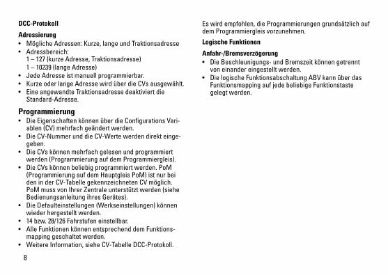
DCC-Protokoll
Adressierung• MöglicheAdressen:Kurze,langeundTraktionsadresse• Adressbereich:
1 – 127 (kurze Adresse, Traktionsadresse) 1 – 10239 (lange Adresse)• JedeAdresseistmanuellprogrammierbar.• KurzeoderlangeAdressewirdüberdieCVsausgewählt.• EineangewandteTraktionsadressedeaktiviertdie
Standard-Adresse.
Programmierung• DieEigenschaftenkönnenüberdieConfigurationsVari-
ablen (CV) mehrfach geändert werden. • DieCV-NummerunddieCV-Wertewerdendirekteinge-
geben.• DieCVskönnenmehrfachgelesenundprogrammiert
werden (Programmierung auf dem Programmiergleis).• DieCVskönnenbeliebigprogrammiertwerden.PoM
(Programmierung auf dem Hauptgleis PoM) ist nur bei den in der CV-Tabelle gekennzeichneten CV möglich. PoM muss von Ihrer Zentrale unterstützt werden (siehe Bedienungsanleitung ihres Gerätes).
• DieDefaulteinstellungen(Werkseinstellungen)könnenwieder hergestellt werden.
• 14bzw.28/126Fahrstufeneinstellbar.• AlleFunktionenkönnenentsprechenddemFunktions-
mapping geschaltet werden.• WeitereInformation,sieheCV-TabelleDCC-Protokoll.
Es wird empfohlen, die Programmierungen grundsätzlich auf dem Programmiergleis vorzunehmen.
Logische Funktionen
Anfahr-/Bremsverzögerung• DieBeschleunigungs-undBremszeitkönnengetrennt
von einander eingestellt werden. • DielogischeFunktionsabschaltungABVkannüberdas
Funktionsmapping auf jede beliebige Funktionstaste gelegt werden.
9
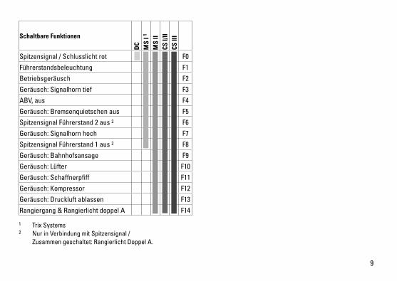
Schaltbare Funktionen
DC
MS
I 1
MS
IICS
I/II
CS II
I
Spitzensignal / Schlusslicht rot F0
Führerstandsbeleuchtung F1
Betriebsgeräusch F2
Geräusch:Signalhorntief F3
ABV, aus F4
Geräusch:Bremsenquietschenaus F5
Spitzensignal Führerstand 2 aus 2 F6
Geräusch:Signalhornhoch F7
Spitzensignal Führerstand 1 aus 2 F8
Geräusch:Bahnhofsansage F9
Geräusch:Lüfter F10
Geräusch:Schaffnerpfiff F11
Geräusch:Kompressor F12
Geräusch:Druckluftablassen F13
Rangiergang & Rangierlicht doppel A F14
1 Trix Systems2 Nur in Verbindung mit Spitzensignal / Zusammengeschaltet:RangierlichtDoppelA.
10
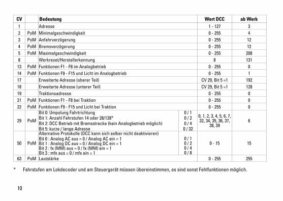
CV Bedeutung Wert DCC ab Werk 1 Adresse 1 - 127 3 2 PoM Minimalgeschwindigkeit 0 - 255 43 PoM Anfahrverzögerung 0 - 255 124 PoM Bremsverzögerung 0 - 255 125 PoM Maximalgeschwindigkeit 0 - 255 2088 Werkreset/Herstellerkennung 8 131
13 PoM Funktionen F1 - F8 im Analogbetrieb 0 - 255 014 PoM Funktionen F9 - F15 und Licht im Analogbetrieb 0 - 255 117 Erweiterte Adresse (oberer Teil) CV29,Bit5=1 19218 Erweiterte Adresse (unterer Teil) CV29,Bit5=1 12819 Traktionsadresse 0 - 255 021 PoM Funktionen F1 - F8 bei Traktion 0 - 255 022 PoM Funktionen F9 - F15 und Licht bei Traktion 0 - 255 0
29 PoM
Bit0:UmpolungFahrtrichtung Bit1:AnzahlFahrstufen14oder28/128* Bit2:DCCBetriebmitBremsstrecke(keinAnalogbetriebmöglich) Bit5:kurze/langeAdresse
0 / 1 0 / 2 0 / 4 0 / 32
0, 1, 2, 3, 4, 5, 6, 7, 32, 34, 35, 36, 37,
38, 396
50 PoM
Alternative Protokolle (DCC kann sich selber nicht deaktivieren)Bit0:AnalogACaus=0/AnalogACein=1 Bit1:AnalogDCaus=0/AnalogDCein=1 Bit2:fx(MM)aus=0/fx(MM)ein=1 Bit3:mfxaus=0/mfxein=1
0 / 1 0 / 2 0 / 4 0 / 8
0 - 15 15
63 PoM Lautstärke 0 - 255 255
* FahrstufenamLokdecoderundamSteuergerätmüssenübereinstimmen,essindsonstFehlfunktionenmöglich.
11
• Built-inheadlightsthatchangeoverwiththedirectionoftravel. They can be turned on and off in digital operation.
• Minimumradiusforoperationis360mm/14-3/16“.
Multi-Protocol Operation Analog OperationThis decoder can also be operated on analog layouts or ar-eas of track that are analog. The decoder recognizes alter-nating current (DC) and automatically adapts to the analog track voltage. All functions that were set under mfx or DCC for analog operation are active (see Digital Operation).
Digital OperationThe decoders are multi-protocol decoders. These decoders canbeusedunderthefollowingdigitalprotocols:mfxorDCC.The digital protocol with the most possibilities is the highest order digital protocol. The sequence of digital protocols in descendingorderis: Priority1:mfx Priority2:DCC Priority3:DCNote: If two or more digital protocols are recognized in the track, the decoder automatically takes on the highest value digital protocol.For example, if mfx & DCC are recognized, the mfx digital protocol is taken on by the decoder. Individual protocols can be deactivated with Parameter CV 50.Note: Please note that not all functions are possible in all digital protocols. Several settings for functions, which are supposed to be active in analog operation, can be done under mfx and DCC.
Safety Notes• Thislocomotiveisonlytobeusedwiththeoperating
system it is designed for.• Analogmax.15voltsDC,digitalmax.22voltsAC.• Thislocomotivemustneverbesuppliedwithpowerfrom
more than one power pack.• Pleasemakenoteofthesafetynotesintheinstructions
for your operating system.• Thefeedertrackmustbeequippedtopreventinter-
ference with radio and television reception, when the locomotive is to be run in conventional operation. The 611 655 interference suppression set is to be used for this purpose. The interference suppression set is not suitable for digital operation.
• WARNING! Sharp edges and points required for operation.• Donotexposethemodeltodirectsunlight,extreme
changes in temperature, or high humidity. • TheLEDsinthisitemcorrespondtoLaserClass1accor-
ding to Standard EN 60825-1.
Important Notes• Theoperatinginstructionsandthepackagingareacom-
ponent part of the product and must therefore be kept as well as transferred along with the product to others.
• PleaseseeyourauthorizedTrixdealerforrepairsorspare parts.
• Thewarrantycardincludedwiththisproductspecifiesthe warranty conditions.
• Disposing:www.maerklin.com/en/imprint.html• ThefullrangeoffunctionsisonlyavailableunderTrix
Systems and under DCC and mfx.
12
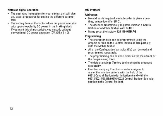
Notes on digital operation • Theoperatinginstructionsforyourcentralunitwillgive
you exact procedures for setting the different parame-ters.
• Thesettingdoneatthefactorydoesnotpermitoperationwith opposite polarity DC power in the braking block. If you want this characteristic, you must do without conventionalDCpoweroperation(CV29/Bit2=0).
mfx Protocol
Addresses • Noaddressisrequired;eachdecoderisgivenaone-
time, unique identifier (UID).• ThedecoderautomaticallyregistersitselfonaCentral
Station or a Mobile Station with its UID.• Namesetatthefactory:120 140-9 DB AG
Programming • Thecharacteristicscanbeprogrammedusingthe
graphic screen on the Central Station or also partially with the Mobile Station.
• AlloftheConfigurationVariables(CV)canbereadandprogrammed repeatedly.
• Theprogrammingcanbedoneeitheronthemaintrackorthe programming track.
• Thedefaultsettings(factorysettings)canbeproducedrepeatedly.
• Functionmapping:Functionscanbeassignedtoany of the function buttons with the help of the 60212 Central Station (with limitations) and with the 60213/60214/60215/60216/60226 Central Station (See help section in the Central Station).
13
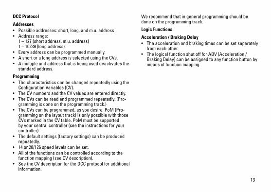
DCC Protocol
Addresses • Possibleaddresses:short,long,andm.u.address• Addressrange:
1 – 127 (short address, m.u. address) 1 – 10239 (long address)
• Everyaddresscanbeprogrammedmanually.• AshortoralongaddressisselectedusingtheCVs.• Amultipleunitaddressthatisbeinguseddeactivatesthe
standard address.
Programming• Thecharacteristicscanbechangedrepeatedlyusingthe
Configuration Variables (CV).• TheCVnumbersandtheCVvaluesareentereddirectly.• TheCVscanbereadandprogrammedrepeatedly.(Pro-
gramming is done on the programming track.)• TheCVscanbeprogrammed,asyoudesire.PoM(Pro-
gramming on the layout track) is only possible with those CVs marked in the CV table. PoM must be supported by your central controller (see the instructions for your controller).
• Thedefaultsettings(factorysettings)canbeproducedrepeatedly.
• 14or28/126speedlevelscanbeset.• Allofthefunctionscanbecontrolledaccordingtothe
function mapping (see CV description).• SeetheCVdescriptionfortheDCCprotocolforadditional
information.
We recommend that in general programming should be done on the programming track.
Logic Functions
Acceleration / Braking Delay• Theaccelerationandbrakingtimescanbesetseparately
from each other. • ThelogicalfunctionshutoffforABV(Acceleration/
Braking Delay) can be assigned to any function button by means of function mapping.
14
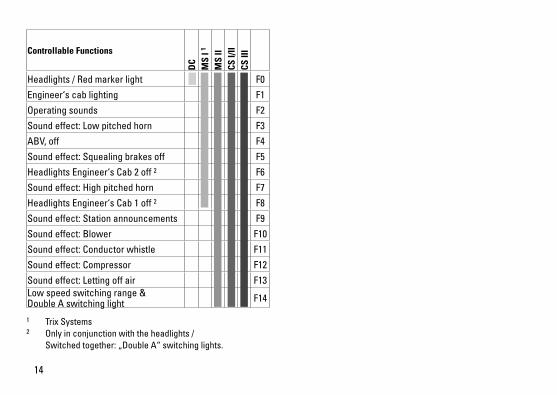
Controllable Functions
DC
MS
I 1
MS
IICS
I/II
CS II
I
Headlights / Red marker light F0
Engineer‘s cab lighting F1
Operating sounds F2
Soundeffect:Lowpitchedhorn F3
ABV, off F4
Soundeffect:Squealingbrakesoff F5
Headlights Engineer‘s Cab 2 off 2 F6
Soundeffect:Highpitchedhorn F7
Headlights Engineer‘s Cab 1 off 2 F8
Soundeffect:Stationannouncements F9
Soundeffect:Blower F10
Soundeffect:Conductorwhistle F11
Soundeffect:Compressor F12
Soundeffect:Lettingoffair F13Low speed switching range & Double A switching light F14
1 Trix Systems2 Only in conjunction with the headlights / Switchedtogether:„DoubleA“switchinglights.
15
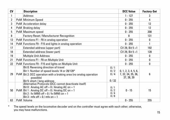
* Thespeedlevelsonthelocomotivedecoderandonthecontrollermustagreewitheachother;otherwise, you may have malfunctions.
CV Discription DCC Value Factory-Set 1 Address 1 - 127 3 2 PoM Minimum Speed 0 - 255 43 PoM Acceleration delay 0 - 255 124 PoM Braking delay 0 - 255 125 PoM Maximum speed 0 - 255 2088 Factory Reset / Manufacturer Recognition 8 131
13 PoM Functions F1 - F8 in analog operation 0 - 255 014 PoM Functions F9 - F15 and lights in analog operation 0 - 255 117 Extended address (upper part) CV29,Bit5=1 19218 Extended address (lower part) CV29,Bit5=1 12819 Multiple Unit Address 0 - 255 021 PoM Functions F1 - F8 on Multiple Unit 0 - 255 022 PoM Functions F9 - F15 and lights on Multiple Unit 0 - 255 0
29 PoM
Bit0:ReversingdirectionoftravelBit1:Numberofspeedlevels14or28/128*Bit2:DCCoperationwithabrakingarea(noanalogoperation possible) Bit5:short/longaddress
0 / 1 0 / 2 0 / 4
0 / 32
0, 1, 2, 3, 4, 5, 6, 7, 32, 34, 35, 36,
37, 38, 396
50 PoM
Alternative Protocols (DCC cannot deactivate itself) Bit0:AnalogACoff=0/AnalogACon=1 Bit1:AnalogDCoff=0/AnalogDCon=1 Bit2:fx(MM)off=0/fx(MM)on=1 Bit3:mfxoff=0/mfxon=1
0 / 1 0 / 2 0 / 4 0 / 8
0 - 15 15
63 PoM Volume 0 - 255 255
16
Remarques importantes sur la sécurité • Lalocomotivenepeutêtreutiliséequ‘aveclesystème
d‘exploitation indiqué.• Analogiquemax.15Volt=,digitalmax.22Volt~.• Lalocomotivenepeutpasêtrealimentéeélectriquement
par plus d‘une source de courant à la fois.• Ilestimpératifdetenircomptedesremarquessurla
sécurité décrites dans le mode d‘emploi de votre système d‘exploitation.
• Pour l’exploitation de la locomotive en mode convention-nel, la voie de raccordement doit être déparasitée. A cet effet, utiliser le set de déparasitage réf. 611 655. Le set de déparasitage ne convient pas pour l’exploitation en mode numérique.
• ATTENTION! Pointes et bords coupants lors du fonctionne-ment du produit.
• Nepasexposerlemodèleàunensoleillementdirect,à de fortes variations de température ou à un taux d‘humidité important.
• LesDELinstalléescorrespondentàlaclasselaser1selon la norme EN 60825-1.
Information importante• Lanoticed‘utilisationetl’emballagefontpartieintégrante
du produit ; ils doivent donc être conservés et, le cas échéant, transmis avec le produit.
• Pourtouteréparationouremplacementdepièces,adres-sez vous à votre détaillant-spécialiste Trix.
• Garantielégaleetgarantiecontractuelleconformémentau certificat de garantie ci-joint.
• Elimination:www.maerklin.com/en/imprint.html• L’intégralitédesfonctionsestdisponibleuniquementen
exploitation Trix Systems, DCC et mfx. • Feuxdesignalisations‘inversantselonlesensdemar-
che; feux commutables en exploitation digital. • Rayonminimald’inscriptionencourbe360mm.
Mode multiprotocole Mode analogiqueOn peut aussi faire fonctionner le décodeur sur des instal-lations ou des sections de voie analogiques. Le décodeur identifie automatiquement la tension de voie analogique (DC). Toutes les fonctions qui ont été paramétrée pour le mode analogique sous mfx ou sous DCC sont actives (voir mode numérique).
Mode numériqueLes décodeur sont des décodeur multiprotocole. Le décodeur peut être utilisé avec les protocoles numériques suivants:mfx,DCCLe protocole numérique offrant les possibilités les plus nombreuses est le protocole numérique à bit de poids fort. La hiérarchisation des protocoles numériques est descendante: Priorité1:mfx Priorité2:DCC Priorité3:DCIndication : Si deux ou plus de deux protocoles numériques sont reconnus sur la voie, le décodeur choisit automatique-ment le protocole numérique le plus significatif. Entre les
17
protocoles mfx & DCC par exemple, le décodeur choisira le protocole numérique mfx. Vous pouvez désactiver les différents protocoles via le paramètre CV 50.Indication : remarquez que toutes les fonctions ne peuvent pas être actionnées dans tous les protocoles numériques. Sous mfx et sous DCC, il est possible de procéder à quelques paramétrages de fonctions devant être actives dans le cadre de l’exploitation analogique.
Remarques relatives au fonctionnement en mode digital • Encequiconcernelaprocédurederéglagedesdivers
paramètres, veuillez vous référer au mode d‘emploi de votre centrale de commande multitrain.
• L’exploitationaveccourantcontinudepolaritéinversedans les sections de freinage n’est pas possible avec le réglage d’usine. Si cette propriété est désirée, il faut alors renoncer à l’exploitation conventionnelle en cou-rantcontinu(CV29/Bit2=0).
Protocole mfx
Adressage • Aucuneadressen’estnécessaire,ledécodeurreçoittou-
tefois une identification unique et non équivoque (UID).• AvecsonUID,ledécodeurindiqueautomatiquement
à une station centrale ou à une station mobile qu’il est connecté.
• Nomencodeeenusine:120 140-9 DB AG
Programmation• Lescaractéristiquespeuventêtreprogramméespar
l’intermédiaire de la couche graphique de la station cen-trale, voire en partie aussi au moyen de la station mobile.
• Touteslesconfigurationsvariables(CV)peuventêtreluesetprogramméesdefaçonréitérée.
• Laprogrammationpeutêtreréaliséesoitsurlavoieprincipale, soit sur la voie de programmation.
• Lesparamétragespardéfaut(paramétragesusine)peuvent être rétablis.
• Mappagedesfonctions:lesfonctionspeuventêtreaffectées à de quelconques touches de fonction au moyen de la station centrale (60212) (restreinte) et avec la station centrale 60213/60214/60215/60216/60226 (voir Aide au niveau de la station centrale).
18
Protocole DCC
Adressage• Adressepossibles:Courtes,longuesetadressesdetraction• Catégoried’adresse:
1 à 127 (adresses courtes, adresses de traction) 1 à 10239 (adresses longues)
• Chaqueadresseestprogrammablemanuellement.• L’adressebrèveoulongueestchoisieparl’intermédiaire
des CVs.• Uneadressedetractionutiliséedésactivel’adresse
standard.
Programmation• Lescaractéristiquespeuventêtremodifiéesdefaçon
réitérée par l’intermédiaire des variables de configuration (CVs).
• Touteslesconfigurationsvariables(CV)peuventêtreluesetprogramméesdefaçonréitérée.
• Laprogrammationpeutêtreréaliséesoitsurlavoieprincipale, soit sur la voie de programmation.
• LesCVpeuventêtreprogramméeslibrement.LaPoM(programmation sur la voie principale) est possible uniquement pour les CV signalées dans le tableau des CV. La PoM doit être prise en charge par votre centrale (voir la notice d’utilisation de votre appareil).
• Lesparamétragespardéfaut(paramétragesusine)peuvent être rétablis.
• 14voire28/126cransdemarchesontparamétrables.
• Touteslesfonctionspeuventêtrecommutéesenfonctiondu mappage des fonctions (voir le descriptif des CVs).
• Pourtouteinformationcomplémentaire,voirletableaudes CVs, protocole DCC.
Il est recommandé, de réaliser la programmation, fonda-mentalement, sur la voie de programmation.
Fonctions logiques
Temporisation d’accélération et de freinage (TAF)• Lestempsd’accélérationetdefreinagepeuventêtre
définis indépendamment l’un de l’autre. • LadésactivationdelafonctionlogiqueTAFpeutêtre
affectée à n’importe quelle touche de fonction via le mappage de fonctions.
19
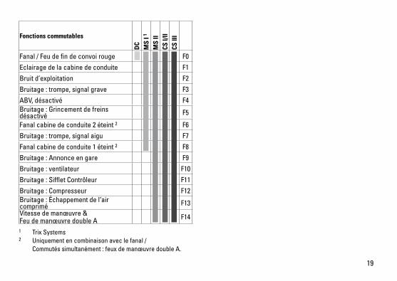
Fonctions commutables
DC
MS
I 1
MS
IICS
I/II
CS II
I
Fanal / Feu de fin de convoi rouge F0
Eclairage de la cabine de conduite F1
Bruit d’exploitation F2
Bruitage:trompe,signalgrave F3
ABV, désactivé F4Bruitage:Grincementdefreinsdésactivé F5
Fanal cabine de conduite 2 éteint 2 F6
Bruitage:trompe,signalaigu F7
Fanal cabine de conduite 1 éteint 2 F8
Bruitage:Annonceengare F9
Bruitage:ventilateur F10
Bruitage:SiffletContrôleur F11
Bruitage:Compresseur F12Bruitage:Échappementdel‘aircomprimé F13Vitesse de manœuvre & Feu de manœuvre double A F14
1 Trix Systems2 Uniquement en combinaison avec le fanal / Commutéssimultanément:feuxdemanœuvredoubleA.
20
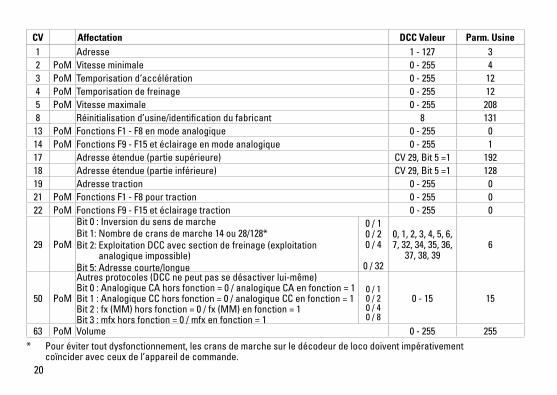
CV Affectation DCC Valeur Parm. Usine 1 Adresse 1 - 127 3 2 PoM Vitesse minimale 0 - 255 43 PoM Temporisation d‘accélération 0 - 255 124 PoM Temporisation de freinage 0 - 255 125 PoM Vitesse maximale 0 - 255 2088 Réinitialisation d’usine/identification du fabricant 8 131
13 PoM Fonctions F1 - F8 en mode analogique 0 - 255 014 PoM Fonctions F9 - F15 et éclairage en mode analogique 0 - 255 117 Adresse étendue (partie supérieure) CV29,Bit5=1 19218 Adresse étendue (partie inférieure) CV29,Bit5=1 12819 Adresse traction 0 - 255 021 PoM Fonctions F1 - F8 pour traction 0 - 255 022 PoM Fonctions F9 - F15 et éclairage traction 0 - 255 0
29 PoM
Bit0:InversiondusensdemarcheBit1:Nombredecransdemarche14ou28/128*Bit2:ExploitationDCCavecsectiondefreinage(exploitation analogique impossible) Bit5:Adressecourte/longue
0 / 1 0 / 2 0 / 4
0 / 32
0, 1, 2, 3, 4, 5, 6, 7, 32, 34, 35, 36,
37, 38, 396
50 PoM
Autres protocoles (DCC ne peut pas se désactiver lui-même) Bit0:AnalogiqueCAhorsfonction=0/analogiqueCAenfonction=1 Bit1:AnalogiqueCChorsfonction=0/analogiqueCCenfonction=1 Bit2:fx(MM)horsfonction=0/fx(MM)enfonction=1 Bit3:mfxhorsfonction=0/mfxenfonction=1
0 / 1 0 / 2 0 / 4 0 / 8
0 - 15 15
63 PoM Volume 0 - 255 255* Pourévitertoutdysfonctionnement,lescransdemarchesurledécodeurdelocodoiventimpérativement
coïncider avec ceux de l’appareil de commande.
21
Veiligheidsvoorschriften• Delocmagalleenmeteendaarvoorbestemdbedrijfssys-
teem gebruikt worden.• Analoogmax.15Volt=,digitaalmax.22Volt~.• Delocmagnietvanuitmeerdanéénstroomvoorziening
gelijktijdig gevoed worden.• Leesookaandachtigdeveiligheidsvoorschrifteninde
gebruiksaanwijzing van uw bedrijfssysteem. • Voorhetconventionelebedrijfmetdelocdientde
aansluitrail te worden ontstoort. Hiervoor dient men de ontstoor-set 611 655 te gebruiken. Voor het digitale bedrijf is deze ontstoor-set niet geschikt.
• OPGEPAST! Functionele scherpe kanten en punten.• Stelhetmodelnietblootaanindirectezonnestraling,
sterke temperatuurwisselingen of hoge luchtvochtigheid.• IngebouwdeLED’skomenovereenmetdelaserklasse1
volgens de norm EN 60825-1. Belangrijke aanwijzing• Degebruiksaanwijzingendeverpakkingzijneenbe-
standdeel van het product en dienen derhalve bewaard en meegeleverd te worden bij het doorgeven van het product.
• VoorreparatiesenonderdelenkuntzichtotUwTrixhandelaar wenden.
• Vrijwaringengarantieovereenkomstighetbijgevoegdegarantiebewijs.
• Afdanken:www.maerklin.com/en/imprint.html• Devolledigetoegangtotallefunctiesisalleenmogelijk
met Trix Systems, DCC of met mfx bedrijf.
• Ingebouwde,rijrichtingsafhankelijkefrontverlichtingisinhet digitaalsysteem schakelbaar.
• Minimaleteberijdenradius:360mm.
MultiprotocolbedrijfAnaloogbedrijfDe decoder kan ook op analoge modelbanen of spoortra-jecten gebruikt worden. De decoder herkent de analoge gelijkspanning (DC) automatisch en past zich aan de analoge railspanning aan. Alle functies die onder mfx of DCC voor het analoge bedrijf zijn ingesteld, worden geactiveerd (zie digitaalbedrijf).
DigitaalbedrijfDe Decoder is een multiprotocoldecoder. De decoder kan onderdevolgendedigitaleprotocolleningezetworden:mfx,DCC. Het digitaalprotocol met de meeste mogelijkheden is het primaire digitaalprotocol. De volgorde van de digitaalproto-collenisafnemendinmogelijkheden: Prioriteit1:mfx Prioriteit2:DCC Prioriteit3:DCOpmerking: Als er twee of meer digitale protocollen op de rails worden herkend, dan neemt de decoder automa-tisch het hoogwaardigste protocol over; bijv. word mfx & DCC herkend, dan wordt het mfx signaal door de decoder overgenomen. De verschillende protocollen kunnen via de parameter CV 50 gedeactiveerd worden.
22
Opmerking: let er op dat niet alle functies in alle digitaal-protocollen mogelijk zijn. Onder mfx of DCC kunnen enkele instellingen, welke in analoogbedrijf werkzaam moeten zijn, ingesteld worden.
Aanwijzingen voor digitale besturing • Hetopdejuistewijzeinstellenvandediverseparame-
ters staat beschreven in de handleiding van uw digitale Centrale.
• Hetbedrijfmettegengepooldegelijkspanningindeafrem-sectie is met de fabrieksinstelling niet mogelijk. Indien deze eigenschap wenselijk is, dan moet worden afgezien van hetconventioneelgelijkstroombedrijf(CV29/Bit2=0).
mfx-protocol
Adressering • Eenadresisnietnodig,elkedecoderheefteenéénmalig
en éénduidig kenmerk (UID).• DedecodermeldtzichvanzelfaanbijhetCentralStation
of Mobile Station met zijn UID.• Naamafdefabriek:120 140-9 DB AG
Programmering • Deeigenschappenkunnenm.b.v.hetgrafischescherm
op het Central Station resp. deels ook met het Mobile Station geprogrammeerd worden.
• Alleconfiguratievariabelen(CV)kunnenvakergelezenen geprogrammeerd worden.
• Deprogrammeringkanzowelophethoofdspooralsophet programmeerspoor gebeuren.
• Dedefault-instellingen(fabrieksinstelling)kunnenweerhersteld worden.
• Functiemapping:functieskunnenmetbehulpvanhetCentral Station 60212 (met beperking) en met het Central Station 60213/60214/60215/60216/60226 aan elke gewenste functietoets worden toegewezen (zie het helpbestand in het Central Station).
23
DCC-protocol
Adressering • Mogelijkeadressen:kort,langentractieadres• Adresbereik:
1 – 127 (kort adres, tractieadres) 1 – 10239 (lange adres)
• Elkadresishandmatigprogrammeerbaar.• KortoflangadreswordtviadeCVgekozen.• Eentoegepasttractieadresdeactiveerthetstandaardad-
res.
Programmering• Deeigenschappenvandedecoderkunnenviadeconfi-
guratie variabelen (CV) vaker gewijzigd worden.• DeCV-nummersendeCV-waardenwordendirectinge-
voerd.• DeCV’skunnenvakergelezenengeprogrammeerd
worden (programmering op het programmeerspoor).• DeCVskunnennaarwensgeprogrammeerdworden.
PoM (Programmering op het hoofdspoor) is alleen moge-lijk bij de in de CV-tabel gemerkte CV. PoM moet door uw centrale ondersteund worden (zie de gebruiksaanwijzing van uw centrale).
• Dedefault-instellingen(fabrieksinstelling)kunnenweerhersteld worden.
• 14resp.28/126rijstappeninstelbaar.• Allefunctieskunnenovereenkomstigdefunctiemapping
geschakeld worden (zie CV-beschrijving).• Voorverdereinformatie,ziedeCV-tabelDCC-protocol.
Het is aan te bevelen om het programmeren alleen op het programmeerspoor uit te voeren.
Fysieke functies
Optrek en afremvertraging• Deoptrek-enafremvertragingkunnenonafhankelijkvan
elkaar ingesteld worden. • DelogischeuitschakelfunctieABV(optrek-enafremver-
traging) kan met de functiemapping aan elke gewenste functietoets toegewezen worden.
24
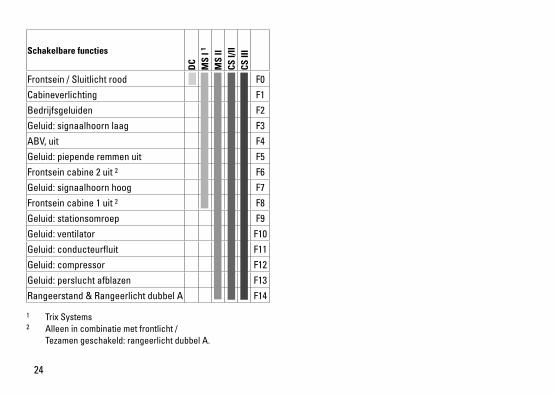
Schakelbare functies
DC
MS
I 1
MS
IICS
I/II
CS II
I
Frontsein / Sluitlicht rood F0
Cabineverlichting F1
Bedrijfsgeluiden F2
Geluid:signaalhoornlaag F3
ABV, uit F4
Geluid:piependeremmenuit F5
Frontsein cabine 2 uit 2 F6
Geluid:signaalhoornhoog F7
Frontsein cabine 1 uit 2 F8
Geluid:stationsomroep F9
Geluid:ventilator F10
Geluid:conducteurfluit F11
Geluid:compressor F12
Geluid:persluchtafblazen F13
Rangeerstand & Rangeerlicht dubbel A F14
1 Trix Systems2 Alleen in combinatie met frontlicht / Tezamengeschakeld:rangeerlichtdubbelA.
25
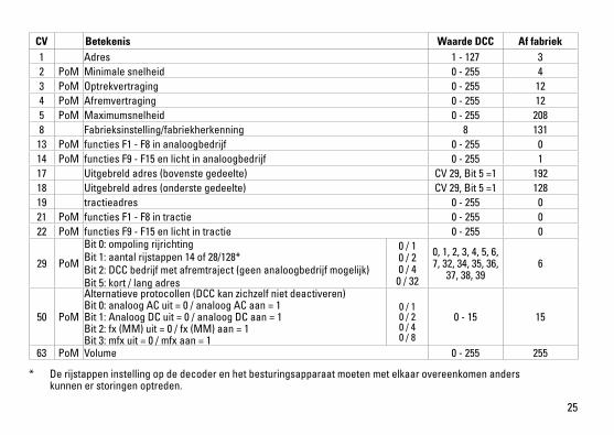
* Derijstappeninstellingopdedecoderenhetbesturingsapparaatmoetenmetelkaarovereenkomenanders kunnen er storingen optreden.
CV Betekenis Waarde DCC Af fabriek1 Adres 1 - 127 3 2 PoM Minimale snelheid 0 - 255 43 PoM Optrekvertraging 0 - 255 124 PoM Afremvertraging 0 - 255 125 PoM Maximumsnelheid 0 - 255 2088 Fabrieksinstelling/fabriekherkenning 8 131
13 PoM functies F1 - F8 in analoogbedrijf 0 - 255 014 PoM functies F9 - F15 en licht in analoogbedrijf 0 - 255 117 Uitgebreld adres (bovenste gedeelte) CV29,Bit5=1 19218 Uitgebreld adres (onderste gedeelte) CV29,Bit5=1 12819 tractieadres 0 - 255 021 PoM functies F1 - F8 in tractie 0 - 255 022 PoM functies F9 - F15 en licht in tractie 0 - 255 0
29 PoM
Bit0:ompolingrijrichtingBit1:aantalrijstappen14of28/128*Bit2:DCCbedrijfmetafremtraject(geenanaloogbedrijfmogelijk)Bit5:kort/langadres
0 / 1 0 / 2 0 / 4
0 / 32
0, 1, 2, 3, 4, 5, 6, 7, 32, 34, 35, 36,
37, 38, 396
50 PoM
Alternatieve protocollen (DCC kan zichzelf niet deactiveren) Bit0:analoogACuit=0/analoogACaan=1 Bit1:AnaloogDCuit=0/analoogDCaan=1 Bit2:fx(MM)uit=0/fx(MM)aan=1 Bit3:mfxuit=0/mfxaan=1
0 / 1 0 / 2 0 / 4 0 / 8
0 - 15 15
63 PoM Volume 0 - 255 255

26
27

28

29
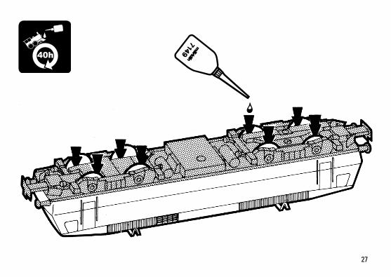
40h
30
Det
ails
der
Dar
stel
-lu
ng k
önne
n vo
n de
m
Mod
ell a
bwei
chen
.
7
7
2
3
9
9
10
11 12
12
12
12
14
1519
22
15
23
20
13
16
17
22
1
8
9
11
17
16
18
21
18
14
1518
18
15
6
2
1
5
4
31
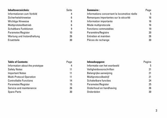
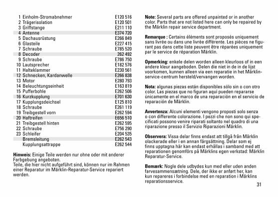
Note: Several parts are offered unpainted or in another color. Parts that are not listed here can only be repaired by the Märklin repair service department.
Remarque : Certains éléments sont proposés uniquement sans livrée ou dans une livrée différente. Les pièces ne figu-rant pas dans cette liste peuvent être réparées uniquement par le service de réparation Märklin.
Opmerking: enkele delen worden alleen kleurloos of in een andere kleur aangeboden. Delen die niet in de in de lijst voorkomen, kunnen alleen via een reparatie in het Märklin-service-centrum hersteld/vervangen worden.
Nota: algunas piezas están disponibles sólo sin o con otro color. Las piezas que no figuran aquí pueden repararse únicamente en el marco de una reparación en el servicio de reparación de Märklin.
Avvertenza: Alcuni elementi vengono proposti solo senza o con differente colorazione. I pezzi che non sono qui spe-cificati possono venire riparati soltanto nel quadro di una riparazione presso il Servizio Riparazioni Märklin.
Observera: Vissa delar finns endast att tillgå från Märklin olackerade eller i en annan färgsättning. Delar som ej finns upptagna här kan endast erhållas i samband med att reparationengenomförspåMärklinsegenverkstad:MärklinReparatur-Service.
Bemærk: Nogle dele udbydes kun med eller uden anden farvesammensætning. Dele, der ikke er anført her, kan kun repareres i forbindelse med en reparation i Märklins reparationsservice.
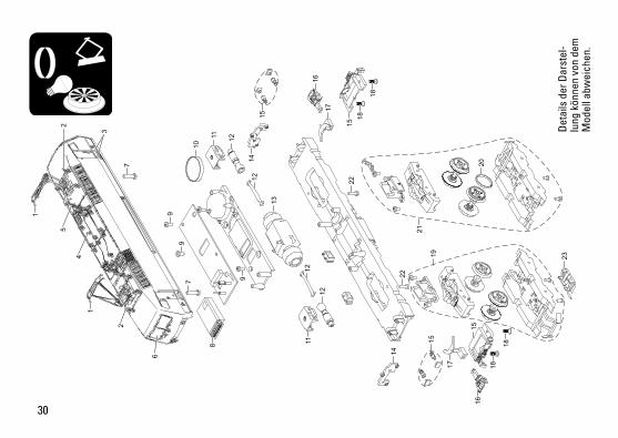
1 Einholm-Stromabnehmer E120 516 2 Trägerisolation E120 501 3 Griffstange E211 110 4 Antenne E374 720 5 Dachausrüstung E266 849 6 Glasteile E227 415 7 Schraube E785 520 8 Decoder 262 492 9 Schraube E786 750 10 Lautsprecher E182 576 11 Halteklammer E230 561 12 Schnecken, Kardanwelle E266 838 13 Motor E280 793 14 Beleuchtungseinheit E163 819 15 Pufferbohle E262 506 16 Kurzkupplung E701 630 17 Kupplungsdeichsel E125 810 18 Schraube E261 119 19 Treibgestell vorn E262 594 20 Haftreifen E656 510 21 Treibgestell hinten E262 595 22 Schraube E756 290 23 Schleifer E204 535 Bremsleitung E262 543 Kupplungsattrappe E262 544
Hinweis: Einige Teile werden nur ohne oder mit anderer Farbgebung angeboten. Teile, die hier nicht aufgeführt sind, können nur im Rahmen einer Reparatur im Märklin-Reparatur-Service repariert werden.

Gebr. Märklin & Cie. GmbH Stuttgarter Straße 55 - 57 73033 Göppingen Germanywww.trix.de
265669/1016/Sc1EfÄnderungen vorbehalten
© Gebr. Märklin & Cie. GmbH
Due to different legal requirements regarding electro-magnetic compatibility, this item may be used in the USA only after separate certification for FCC com-pliance and an adjustment if necessary. Use in the USA without this certification is not permitted and absolves us of any liability. If you should want such certification to be done, please contact us – also due to the additional costs incurred for this.
www.maerklin.com/en/imprint.html

DK
S Modell der Elektrolokomotive BR 120.1
22686

2
3
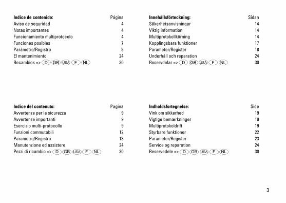
Indice de contenido: PáginaAviso de seguridad 4Notas importantes 4Funcionamiento multiprotocolo 4Funciones posibles 7Parámetro/Registro 8El mantenimiento 24Recambios => D GB USA F NL 30
Indice del contenuto: PaginaAvvertenze per la sicurezza 9Avvertenze importanti 9Esercizio multi-protocollo 9Funzioni commutabili 12Parametro/Registro 13Manutenzione ed assistere 24Pezzi di ricambio => D GB USA F NL 30
Innehållsförteckning: SidanSäkerhetsanvisningar 14Viktig information 14Multiprotokollkörning 14Kopplingsbara funktioner 17Parameter/Register 18Underhåll och reparation 24Reservdelar => D GB USA F NL 30
Indholdsfortegnelse: SideVink om sikkerhed 19Vigtige bemærkninger 19Multiprotokoldrift 19Styrbare funktioner 22Parameter/Register 23Service og reparation 24Reservedele => D GB USA F NL 30
4
Aviso de seguridad • Lalocomotorasolamentedebefuncionarenelsistema
que le corresponda. • Analógicasmáx.15voltios=,digitalesmáx.22voltios~.• Laalimentacióndelalocomotoradeberárealizarse
desde una sola fuente de suminitro. • Observenecesariamentelosavisosdeseguridadindica-
dos en las instrucciones correspondientes a su sistema de funcionamiento.
• Paraelfuncionamientoconvencionaldelalocomotoradebensuprimirselasinterferenciasenlavíadeconexióndelaalimentación.Paraellodebeemplearseelsetsupresordeinterferencias611655.
• ¡ATENCIÓN! Esquinas y puntas afiladas condicionadas a lafunción.
• Noexponerelmodeloenminiaturaalaradiaciónsolardirecta,aoscilacionesfuertesdetemperaturaoaunahumedad del aire elevada.
• LosLEDsincorporadoscorrespondenalaclasede láser1segúnlanormaeuropeaEN60825-1.
Notas importantes • Lasinstruccionesdeempleoyelembalajeformanparteíntegradelproductoy,porestemotivo,debenguardarseyentregarsejuntoconelproductoenelcasodevenderloo transmitirlo a otro.
• Encasodeprecisarunareparaciónopiezasderecambio,rogamosponerseencontactoconsudistribuidorTrix.
• Responsabilidadygarantíaconformealdocumentodegarantíaqueseadjunta.
• Eliminación:www.maerklin.com/en/imprint.html• LaplenafuncionalidaddefuncionesestádisponiblesóloenTrixSystems,DCCyenmfx.
• Losfarosfrontalesdependendelsentidodelamarcha. EnDigitalsepuedenencenderyapagar.
• Radiomínimodescribe360mm.
Funcionamiento multiprotocoloModo analógicoEl decoder puede utilizarse también en maquetas de trenes otramosdevíaanalógicos.Eldecoderdetectalatcontinuaanalógica(DC)automáticamente,adaptándosealatensióndevíaanalógica.EstánactivastodaslasfuncionesquehayansidoconfiguradasparaelmodoanalógicoenmfxoDCC(véaseMododigital).
Modo digitalLosdecoderssondecodersmultiprotocolo.Eldecoderpuedeutilizarseconlossiguientesprotocolosdigitales:mfx,DCC.El protocolo digital que ofrece el mayor número de posibi-lidades es el protocolo digital de mayor peso. El orden de pesosdelosprotocolosdigitalesesdescendente.: Prioridad1:mfx Prioridad2:DCC Prioridad3:DCNota: Si se detectan en la vía dos o varios protocolos digi-tales,eldecoderasumeautomáticamenteelprotocolodigi-taldemayorvalor;p.ej.,sisedetectamfxyDCC,eldecoderasumeelprotocolodigitalmfx.LosdistintosprotocolossepuedendesactivarmedianteelparámetroCV50.
5
Nota: Tenga presente que no son posibles todas las funcionesentodoslosprotocolosdigitales.EnmfxyDCCpueden configurarse algunos parámetros de funciones que debentenerefectoenelmodoanalógico.
Informaciones para el funcionamiento digital • Deberáconsultarelprocedimientoexactodeconfi-guracióndelosdiversosparámetrosenelmanualdeinstrucciones de la central multitren que desee utilizar.
• Noesposibleelfuncionamientocontensióndecorrientecontinua de polaridad opuesta en el tramo de frenado en funcionamientoenmodoDCC.Sisedeseaestacaracterí-stica,deberenunciarsealfuncionamientoconvencionalconcorrientecontinua(CV29/Bit2=0).
Protocolo mfx
Direccionamiento • Noserequieredireccionamiento,recibiendocadadeco-derunaidentificaciónuniversalmenteúnicaeinequívoca(UID)
• Eldecodersedadealtaautomáticamenteenuna CentralStationoenunaMobileStationconsuUID:
• Nombredefabrica:120 140-9 DB AG
Programación• LascaracterísticaspuedenprogramarsemediantelainterfazgráficadelaCentralStationobienenpartetambién con la Mobile Station.
• EsposibleleeryprogramarmúltiplesvecestodaslasVariablesdeConfiguración(CV).
• Laprogramaciónpuederealizarsebienenlavíaprincipaloenlavíadeprogramación.
• Esposiblerestaurarlaconfiguraciónpordefecto(confi-guracióndefábrica).
• Mapeadodefunciones:lasfuncionespuedenasig-narseacualesquierateclasdefunción(véaseAyudaenlaCentralStation)conayudadelaCentralStati-on60212(conlimitaciones)yconlaCentralStation60213/60214/60215/60216/60226.
6
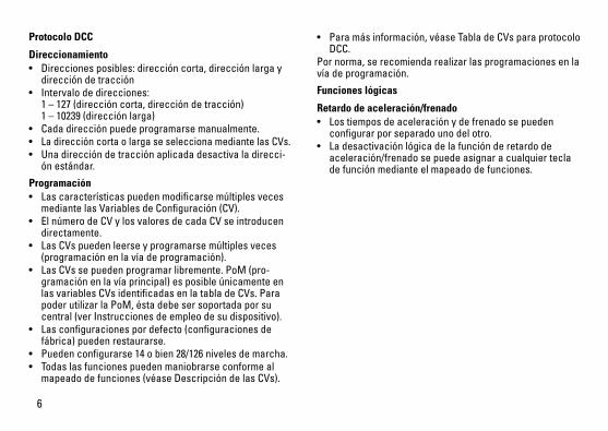
Protocolo DCC
Direccionamiento• Direccionesposibles:direccióncorta,direcciónlargaydireccióndetracción
• Intervalodedirecciones: 1–127(direccióncorta,direccióndetracción) 1–10239(direcciónlarga)
• Cadadirecciónpuedeprogramarsemanualmente.• LadireccióncortaolargaseseleccionamediantelasCVs.• Unadireccióndetracciónaplicadadesactivaladirecci-ónestándar.
Programación• LascaracterísticaspuedenmodificarsemúltiplesvecesmediantelasVariablesdeConfiguración(CV).
• ElnúmerodeCVylosvaloresdecadaCVseintroducendirectamente.
• LasCVspuedenleerseyprogramarsemúltiplesveces(programaciónenlavíadeprogramación).
• LasCVssepuedenprogramarlibremente.PoM(pro-gramaciónenlavíaprincipal)esposibleúnicamenteenlasvariablesCVsidentificadasenlatabladeCVs.ParapoderutilizarlaPoM,éstadebesersoportadaporsucentral(verInstruccionesdeempleodesudispositivo).
• Lasconfiguracionespordefecto(configuracionesdefábrica)puedenrestaurarse.
• Puedenconfigurarse14obien28/126nivelesdemarcha.• Todaslasfuncionespuedenmaniobrarseconformealmapeadodefunciones(véaseDescripcióndelasCVs).
• Paramásinformación,véaseTabladeCVsparaprotocoloDCC.
Pornorma,serecomiendarealizarlasprogramacionesenlavíadeprogramación.
Funciones lógicas
Retardo de aceleración/frenado• Lostiemposdeaceleraciónydefrenadosepueden
configurar por separado uno del otro. • Ladesactivaciónlógicadelafunciónderetardodeaceleración/frenadosepuedeasignaracualquiertecladefunciónmedianteelmapeadodefunciones.
7
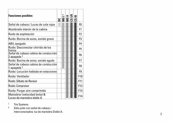
Funciones posibles
DC
MS
I 1
MS
IICS
I/II
CS II
I
Señaldecabeza/Lucesdecolarojas F0
Alumbrado interior de la cabina F1
Ruidodeexplotación F2
Ruido:Bocinadeaviso,sonidograve F3
ABV,apagado F4Ruido:Desconectarchirridodelosfrenos F5Señaldecabezacabinadeconducción2 apagada 2 F6
Ruido:Bocinadeaviso,sonidoagudo F7Señaldecabezacabinadeconducción1 apagada 2 F8
Ruido:Locuciónhabladaenestaciones F9
Ruido:Ventilador F10
Ruido:SilbatodeRevisor F11
Ruido:Compresor F12
Ruido:Purgarairecomprimido F13Maniobrar(velocidadlenta)& LucesdemaniobradobleA F14
1 TrixSystems2 Sólojuntoconseñaldecabeza/ Interconectados:luzdemaniobraDobleA.
8
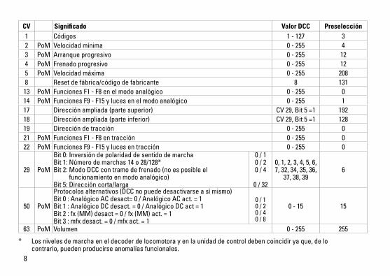
* Losnivelesdemarchaeneldecoderdelocomotorayenlaunidaddecontroldebencoincidiryaque,delo contrario,puedenproducirseanomalíasfuncionales.
CV Significado Valor DCC Preselección1 Códigos 1 - 127 3 2 PoM Velocidad mínima 0-255 43 PoM Arranque progresivo 0-255 124 PoM Frenado progresivo 0-255 125 PoM Velocidadmáxima 0-255 2088 Resetdefábrica/códigodefabricante 8 131
13 PoM FuncionesF1-F8enelmodoanalógico 0-255 014 PoM FuncionesF9-F15ylucesenelmodoanalógico 0-255 117 Direcciónampliada(partesuperior) CV29,Bit5=1 19218 Direcciónampliada(parteinferior) CV29,Bit5=1 12819 Direccióndetracción 0-255 021 PoM FuncionesF1-F8entracción 0-255 022 PoM FuncionesF9-F15ylucesentracción 0-255 0
29 PoM
Bit0:Inversióndepolaridaddesentidodemarcha Bit1:Númerodemarchas14o28/128* Bit2:ModoDCCcontramodefrenado(noesposibleel funcionamientoenmodoanalógico) Bit5:Direccióncorta/larga
0 / 1 0 / 2 0 / 4
0 / 32
0,1,2,3,4,5,6,7,32,34,35,36,37,38,39
6
50 PoM
Protocolosalternativos(DCCnopuededesactivarseasímismo) Bit0:AnalógicoACdesact=0/AnalógicoACact.=1 Bit1:AnalógicoDCdesact.=0/AnalógicoDCact=1 Bit2:fx(MM)desact=0/fx(MM)act.=1 Bit3:mfxdesact.=0/mfxact.=1
0 / 1 0 / 2 0 / 4 0 / 8
0-15 15
63 PoM Volumen 0-255 255
9
Avvertenze per la sicurezza • Talelocomotivadevevenireimpiegatasoltantoconun
sistema di esercizio prestabilito a questo scopo.• Analogicomax.15Volt=,digitalemax.22Volt~.• Lalocomotivanondevevenirealimentatanellostesso
tempo con più di una sorgente di potenza.• Vogliateprestareassolutamenteattenzionealleavverten-
ze di sicurezza nelle istruzioni di impiego per il Vostro sistema di funzionamento.
• Perilfunzionamentotradizionaledellalocomotivailbinario di alimentazione deve essere protetto dai disturbi. A tale scopo si deve impiegare il corredo antidisturbi 611655.TalecorredoantidisturbinonèadattoperilfunzionamentoDigital.
• AVVERTENZA! Per motivi funzionali i bordi e le punte sono spigolosi.
• Nonesponetetalemodelloadalcunirraggiamentosolarediretto,afortiescursioniditemperaturaoppureaelevataumidità dell’aria.
• ILEDincorporaticorrispondonoallacategoriadilaser1secondolaNormaEN60825-1.
Avvertenze importanti• Leistruzionidiimpiegoel’imballaggiocostituisconoun
componente sostanziale del prodotto e devono pertanto venire conservati nonché consegnati insieme in caso di ulteriore cessione del prodotto.
• Perleriparazioniolepartidiricambio,contrattareilrivenditoreTrix.
• Prestazionidigaranziaegaranziainconformitàall’acclu-so certificato di garanzia.
• Smaltimento:www.maerklin.com/en/imprint.html• LacompletadotazionedifunzionièdisponibilesoltantosottoTrixSystems,DCCesottomfx.
• IIluminazioneditestaincorporata,dipendentedalladire-zionedimarcia.CommutabilenelfunzionamentoDigital.
• Raggiominimopercorribile360mm.
Esercizio multi-protocolloEsercizio analogicoTaleDecoderpuòvenirefattofunzionareanchesuimpiantiosezionidibinarioanalogiche.IlDecoderriconosceautomati-camentelatensioneanalogica(DC)esiadeguaallatensioneanalogica del binario. Vi sono attive tutte le funzioni che erano stateimpostateperl’esercizioanalogicosottomfxoppureDCC(sivedaesercizioDigital).
Esercizio DigitalIDecodersonoDecodermulti-protocollo.IlDecoderpuòvenireimpiegatosottoiseguentiprotocolliDigital:mfx,DCC.IlprotocolloDigitalconilmaggiornumerodipossibilitàèilprotocollodigitaledimassimovalore.LasequenzadeiprotocolliDigital,convaloridecrescenti,è: Priorità1:mfx Priorità2:DCC Priorità3:DCAvvertenza: Qualora sul binario vengano riconosciuti due o piùprotocollidigitali,ilDecoderassumeautomaticamenteil protocollo digitale con il valore più elevato; ad es. se vienericonosciutomfx&DCC,vieneassuntodalDecoderilprotocollodigitalemfx.IsingoliprotocollipossonoveniredisattivatimedianteilparametroCV50.
10
Avvertenza: Prestate attenzione al fatto che non tutte le funzionisonopossibiliintuttiiprotocolliDigital.SottomfxeDCCpossonovenireeseguitealcuneimpostazionidifunzio-ni,lequalisarannoefficacinell’esercizioanalogico.
Istruzioni per la funzione digitale • L’esattoprocedimentoperl’impostazionedeidifferenti
parametri siete pregati di ricavarlo dalle istruzioni di servizio della Vostra centrale per molti treni.
• Unfunzionamentocontensionecontinuadipolaritàin-vertitanellasezionedifrenatura,incasodiesercizioconDCC,nonèpossibile.Sesidesideraquestacaratteristica,si deve in tal caso rinunciare al funzionamento tradiziona-leincorrentecontinua(CV29/Bit2=0).
Protocollo mfx
Indirizzamento• Nessunindirizzonecessario,ciascunDecoderriceveunasuaidentificazioneirripetibileeunivoca(UID).
• IlDecodersiannunciaautomaticamenteadunaCentralStationoppureMobileStationconilsuoUID.
• Nomedifabrica:120 140-9 DB AG
Programmazione• LecaratteristichepossonovenireprogrammatetramitelasuperficiegraficadellaCentralStationorispettivamentein parte anche con la Mobile Station.
• TutteleVariabilidiConfigurazione(CV)possonovenireripetutamente lette e programmate.
• Taleprogrammazionepuòavveniresuibinariprincipalioppure sul binario di programmazione.
• Leimpostazionididefault(impostazionidifabbrica)possono venire nuovamente riprodotte.
• Mappaturadellefunzioni:conl’ausiliodellaCentralStation60212(limitatamente)econlaCentralStation60213/60214/60215/60216/60226lefunzionipossonovenireassegnateadeitastifunzioneapiacere(sivedanoleguidediaiutonellaCentralStation).
11
Protocollo DCC
Indirizzamento• Possibiliindirizzi:brevi,lunghieindirizzipertrazioni
multiple• Campodegliindirizzi: 1–127(indirizzibrevi,indirizzipertrazionimultiple) 1–10239(indirizzilunghi)
• Ciascunindirizzoèprogrammabilemanualmente.• L’indirizzobreveolungovieneselezionatotramiteleCV.• Unindirizzodiunitàditrazioneutilizzatodisattival’indiriz-
zo standard.
Programmazione• Lecaratteristichepossonovenireripetutamentemodifi-catetramiteleVariabilidiConfigurazione(CV).
• IlnumerodellaCVedivaloridellaCVvengonointrodottidirettamente.
• LeCVpossonovenireripetutamenteletteeprogrammate(Programmazionesulbinariodiprogrammazione).
• LeCVpossonovenireprogrammatecomesivuole.LaPoM(programmazionesulbinarioprincipale)èpossibilesoltantonelcasodelleCVcontrassegnatenellatabelladelleCV.LaPoMdeveveniresupportatadallaVostraUnitàCentrale(sivedanoleistruzionidiazionamentodelVostroapparato).
• Leimpostazionididefault(impostazionidifabbrica)possono venire nuovamente riprodotte.
• 14 o rispettivamente 26/126 gradazioni di marcia impostabili.
• Tuttelefunzionipossonovenirecommutateinmodorispondenteallamappaturadellefunzioni(sivedaladescrizionedelleCV).
• Perulterioriinformazioni,sivedalatabelladelleCVnelprotocolloDCC.
È consigliabile intraprendere le programmazioni essenzial-mente sul binario di programmazione.
Funzioni logiche
Ritardo di avviamento/frenatura • Laduratadiaccelerazioneedifrenaturapossonovenire
impostate separatamente una dall’altra. • LadisattivazionelogicaditalefunzioneABVpuòvenire
assegnata a piacere a ciascun tasto di funzione mediante la mappatura delle funzioni.
12
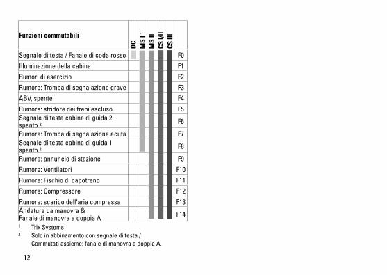
Funzioni commutabili
DC
MS
I 1
MS
IICS
I/II
CS II
I
Segnale di testa / Fanale di coda rosso F0
Illuminazionedellacabina F1
Rumori di esercizio F2
Rumore:Trombadisegnalazionegrave F3
ABV,spente F4
Rumore:stridoredeifreniescluso F5Segnale di testa cabina di guida 2 spento 2 F6
Rumore:Trombadisegnalazioneacuta F7Segnale di testa cabina di guida 1 spento 2 F8
Rumore:annunciodistazione F9
Rumore:Ventilatori F10
Rumore:Fischiodicapotreno F11
Rumore:Compressore F12
Rumore:scaricodell‘ariacompressa F13Andaturadamanovra& Fanale di manovra a doppia A F14
1 TrixSystems2 Solo in abbinamento con segnale di testa / Commutatiassieme:fanaledimanovraadoppiaA.
13
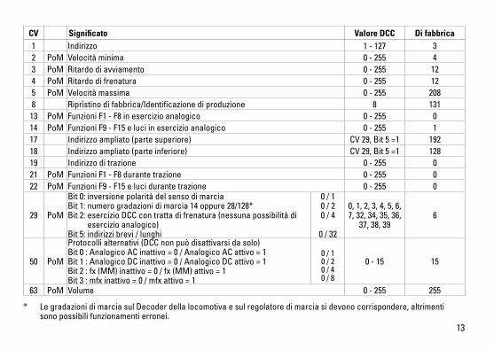
CV Significato Valore DCC Di fabbrica1 Indirizzo 1 - 127 3 2 PoM Velocità minima 0-255 43 PoM Ritardo di avviamento 0-255 124 PoM Ritardo di frenatura 0-255 125 PoM Velocità massima 0-255 2088 Ripristinodifabbrica/Identificazionediproduzione 8 131
13 PoM Funzioni F1 - F8 in esercizio analogico 0-255 014 PoM FunzioniF9-F15eluciinesercizioanalogico 0-255 117 Indirizzoampliato(partesuperiore) CV29,Bit5=1 19218 Indirizzoampliato(parteinferiore) CV29,Bit5=1 12819 Indirizzoditrazione 0-255 021 PoM Funzioni F1 - F8 durante trazione 0-255 022 PoM FunzioniF9-F15elucidurantetrazione 0-255 0
29 PoM
Bit0:inversionepolaritàdelsensodimarcia Bit1:numerogradazionidimarcia14oppure28/128* Bit2:esercizioDCCcontrattadifrenatura(nessunapossibilitàdi esercizioanalogico) Bit5:indirizzibrevi/lunghi
0 / 1 0 / 2 0 / 4
0 / 32
0,1,2,3,4,5,6,7,32,34,35,36,37,38,39
6
50 PoM
Protocollialternativi(DCCnonpuòdisattivarsidasolo) Bit0:AnalogicoACinattivo=0/AnalogicoACattivo=1 Bit1:AnalogicoDCinattivo=0/AnalogicoDCattivo=1 Bit2:fx(MM)inattivo=0/fx(MM)attivo=1 Bit3:mfxinattivo=0/mfxattivo=1
0 / 1 0 / 2 0 / 4 0 / 8
0-15 15
63 PoM Volume 0-255 255
* LegradazionidimarciasulDecoderdellalocomotivaesulregolatoredimarciasidevonocorrispondere,altrimenti sono possibili funzionamenti erronei.
14
Säkerhetsanvisningar • Loketfårendastkörasmeddärtillavsettdriftsystem.• Analogmax.15Volt=,digitalmax.22Volt~.• Loketfårintesamtidigtförsörjasavmeränenkraftkälla.• Beaktaalltidsäkerhetsanvisningarnaibruksanvisningen
som hör till respektive driftsystemet. • Närdenmotorförseddalokdelenskakörasmedkon-
ventionell drift måste anlutningsskenan vara avstörd. Tilldettaanvändermananslutningsgarnityr611655medavstörning och överbelastningsskydd. Avstörningsskyd-det får inte användas vid digital körning.
• VARNING! Funktionsbetingade vassa kanter och spetsar.• Modellenfårinteutsättasfördirektsolljus,häftigatem-peraturväxlingarellerhögluftfuktighet.
• InbyggdaLED(lysdioder)motsvararlaser-klass1enligtEnnorm60825-1.
Viktig information• Bruksanvisningenochförpackningenärendelavproduktenochmåstedärförsparasochalltidmedföljaprodukten.
• KontaktadinTrix-handlareförreparationerellerreserv-delar.
• Garantivillkorframgåravbifogadegarantibevis.• Hanteringsomavfall:www.maerklin.com/en/imprint.html• Fullständigtfunktionsomfångerhållsendastvidanvänd-ningavTrixSystems,DCCellermfx.
• Körriktningsberoendefrontbelysning. Kan kopplas in vid digital drift.
• Kanköraspåenminstaradieav360mm.
MultiprotokollkörningAnalog körningDekodernkanävenanvändasvidkörningpåanalogaanläg-gningarochspåravsnitt.Dekodernkännerautomatisktigenochgodtaranalogkörström,bådeväxelströmochlikström(AC/DC).AllamfxellerDCCfunktionerinställdaföranalogdriftäraktiverade.(v.g.se:Digitalkörning).
Digital körningDecoderärenmultiprotokolldekoder.Dekodernkananvän-dastillsammansmedföljandedigital-protokoll:mfx,Dcc,.Digital-protokolletmedflestfunktionerärhögstprioriterat.Digital-protokolleninordnasifallandeordningsomföljer: Prioritet1:mfx Prioritet2:DCC Prioritet3:fx(DC)Observera: Omtvåellerfleradigital-protokollanvändsviaspåret,såanvänderdekodernautomatisktdethögvärdi-gasteprotokollet.Användst.ex.mfx&DCC,såkommerde-kodernattanvändamfx-digital-protokollet.EnstakaprotokollkanavaktiverasmedhjälpavCV50.Observera: Tänk på att inte alla funktioner kan användas/aktiverasialladigital-protokoll.MedmfxochDCCkanvissafunktionsinställningar göras för att funktionerna ska vara aktiva vid analog körning.
15
Anvisningar för digital drift • DetaljeradeanvisningarförattställainolikaparametrarfinnsibruksanvisningentillErdigitalaflertågs-körkon-troll.
• VidDCC-driftkanmaninteköramedtvåpoliglikspänningpå ett bromsavsnitt. Önskar man ändå genomföra en sådankörning,såmåstemanförlitasigpåkonventionelllikströmsdrift(CV29/Bit2=0).
mfx-protokoll
Adressering • Ingenadressbehövs,varjedekoderharenheltegenochentydigadress(UID).
• DekodernanmälersejautomatiskttillCentralStationochMobileStationviasinUID.
• Namnfrantillverkaren:120 140-9 DB AG
Programmering• EgenskapernakanprogrammerasviaCentralStations
pekskärm och även till vissa delar med Mobile Station. • Såkanävenallakonfigurations-variabler(CV)läsasin
och programmeras.• Programmeringenkangörasantingendirektpåanlägg-
ningens spår eller på programmeringsspåret. • Default-inställningarna(fabrikensinställningar)kan
återskapas.• Mappningavfunktioner:FunktionerkanmedhjälpavCentralStation60212(ivissutsträckning)ochmed CentralStation60213/60214/60215/60216/60226 kopplas till önskadefunktionsknappar(V.g.semerinformationiCentralStation).
16
DCC-protokoll
Adressering• Möjligaadresser:Korta,långaochmultippelkopplings-
adresser• Adressområde: 1–127(kortaadresser,multippelkopplings-adresser) 1–10239(långaadresser)
• Varjeenskildadresskanprogrammerasmanuellt.• KortaellerlångaadresserväljsviaCVn.• Envaldmultippelkopplingsadressavaktiverarstandard-
adresserna.
Programmering• Egenskapernakanändrasfleragångerviakonfigura-tions-variablerna(CV).
• CV-nummerochCV-värdenangesdirekt.• AllaCVnkanläsasochprogrammerasfleragånger(Programmeringgörspåprogrammeringsspåret).
• AllaCvnkanprogrammeras.PoM(Programmeringpåhuvudspåret)kanendastgenomförasmediCV-tabellenmarkeradeCvn.DincentralenhetmåstehastödförPoM(sebruksanvisningensommedföljercentralenheten).
• Defaultinställningar(fabriksinställningar)kanåterskapas.• 14upptill28/126körstegkanställasin.• Samtligafunktionerkankopplasinochmanövrerasenligtfunktions-mappningen.(V.g.seCV-beskrivningen.)
• Förytterligareinformation:V.g.seCV-tabellerDCC-proto-koll.
Vi rekommenderar att endast genomföra programmeringar på programmerings-spåret.
Logiska funktioner
Accelerations-/bromsfördröjning• Accelerations-ochinbromsningstiderkanställasin
separat.• DenlogiskafunktionsavstängningenABVkanvia
funktionsmappning bli tilldelad och styras från önskad funktionsknapp.
17
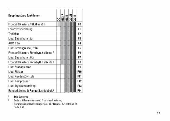
Kopplingsbara funktioner
DC
MS
I 1
MS
IICS
I/II
CS II
I
Frontstrålkastare/Slutljusrött F0
Förarhyttsbelysning F1
Trafikljud F2
Ljud:Signalhornlågt F3
ABV,från F4
Ljud:Bromsgnissel,från F5
Frontstrålkastare Förarhytt 2 släckta 2 F6
Ljud:Signalhornhögt F7
Frontstrålkastare Förarhytt 1 släckta 2 F8
Ljud:Stationsutrop F9
Ljud:Fläktar F10
Ljud:Konduktörvissla F11
Ljud:Kompressor F12
Ljud:Tryckluftsutsläpp F13
Rangerkörning&RangerljusdubbelA F14
1 TrixSystems2 Endast tillsammans med frontstrålkastare / Sammankopplade:Rangerljus,sk.“DoppelA“,vittljusåt båda håll.
18
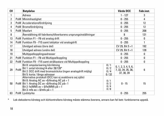
* Lok-dekodernskörstegochkörkontrollenskörstegmåstestämmaöverens,annarskanfelbetr.funktionernauppstå.
CV Betydelse Värde DCC Fabr.inst.1 Adress 1 - 127 3 2 PoM Minimihastighet 0-255 43 PoM Accelerationsfördröjning 0-255 124 PoM Bromsfördröjning 0-255 125 PoM Maxfart 0-255 2088 Återställning till fabrikens/tillverkarens ursprungsinställningar 8 131
13 PoM Funktion F1 – F8 vid analog drift 0-255 014 PoM FunktionF9–F15samtloklyktorvidanalogdrift 0-255 117 Utvidgadadress(övredel) CV29,Bit5=1 19218 Utvidgadadress(undredel) CV29,Bit5=1 12819 Multippelkopplingsadresser 0-255 021 PoM Funktion F1 – F8 vid Multippelkoppling 0-255 022 PoM FunktionF9–F15samtstrålkastarevidMultippelkoppling 0-255 0
29 PoM
Bit0:ompolariseringkörriktning Bit1:antalkörsteg14eller28/128* Bit2:DCCdriftmedbromssträcka(ingenanalogdriftmöjlig) Bit5:korta/långaadresser
0 / 1 0 / 2 0 / 4
0 / 32
0,1,2,3,4,5,6,7,32,34,35,36,37,38,39
6
50 PoM
Alternativaprotokoll(DCCkanejavaktiverasejsjälv) Bit0:AnalogACav=0/AnalogACpå=1 Bit1:AnalogDCav=0/AnalogDCpå=1 Bit2:fx(MM)av=0/fx(MM)på=1 Bit3:mfxav=0/mfxpå=1
0 / 1 0 / 2 0 / 4 0 / 8
0-15 15
63 PoM Ljudstyrka 0-255 255
19
Vink om sikkerhed• Lokomotivetmåkunanvendesmedetdriftssystem,derer
beregnet dertil. • Analogmax.15Volt=,digitalmax.22Volt~.• Lokomotivetmåikkeforsynesframereendénstrømkilde
ad gangen.• Værunderalleomstændighederopmærksompådevinkomsikkerhed,somfindesibrugsanvisningenforDeresdriftssystem.
• Vedkonventioneldriftaflokomotivetskaltilslutningssporetstøjdæmpes.Dertilskalanvendesstøjdæmpningssættet611655.Støjdæmpningssætteterikkeegnettildigitaldrift.
• ADVARSEL! Skarpe kanter og spidser pga. funktionen.• Modellenmåikkeudsættesfordirektesollys,storetemperaturudsvingellerhøjluftfugtighed.
• Deindbyggedelysdiodersvarertillaserklasse1ihenholdtilnormenEN60825-1.
Vigtige bemærkninger• Betjeningsvejledningogemballagehørertilproduktetogskalderforgemmesogmedfølge,hvisproduktetgivesvidere til andre.
• AngåendereparationerellerreservedelebedesDehenvendeDemtilDeresTrix-forhandler.
• Garantiifølgevedlagtegarantibevis.• Bortskafning:www.maerklin.com/en/imprint.html• DetkomplettefunktionsomfangerkuntilrådighedunderTrixSystems,DCCogundermfx.
• Innebygd,kjøreretningsavhengigfrontlys. Kan tændes og slukkes til digitaldrift.
• Farbarmindsteradius360mm.
Multiprotokoldrift AnalogdriftDekoderenkanogsåbenyttespåanalogeanlægellersporafsnit.Dekoderengenkenderautomatiskdenanalogeveksel(DC)ogtilpassersigdenanalogejævnstrøm.Allefunktioner,somindstilledestilanalogdriftundermfxellerDCC,eraktive(sedigitaldrift).
DigitaldriftmSDSoundDecodereermultiprotokoldekodere.Dekoderenkananvendesvedfølgendedigital-protokoller:mfx,DCC.Digital-protokollenmedflestmulighedererdenhøjestran-gerendedigital-protokol.Digital-protokollernesrækkefølgeermedfaldendeværdifølgende: Prioritet1:mfx Prioritet2:DCC Prioritet3:DCBemærk:Hvisdergenkendestoellerfleredigitalproto-kollerpåskinnen,overtagerdekoderenautomatiskdendigitalprotokolmeddenhøjesteværdi;hvismfx&DCCf.eks.genkendes,overtagerdekoderenmfx-digitalprotokollen.EnkelteprotokollerkandeaktiveresviaparameterCV50.Bemærk:Væropmærksompå,atikkeallefunktionerermuligeialledigital-protokoller.VedmfxogDCCkanderforetagesnogleindstillingeraffunktioner,somskalhaveeffekt ved analogdrift.
20
Henvisninger til digitaldrift • Dennøjagtigefremgangsmådetilindstillingafdeforskel-ligeparametrefindesibetjeningsvejledningentilDeresflertogs-central.
• DetervedDCC-driftikkemuligtatanvendedriftmedmodpoletjævnspændingibremseafsnittet.Hvisdenneegenskabønskes,mådergivesafkaldpådenkonventio-nellejævnstrømsdrift(CV29/Bit2=0).
mfx-protokol
Adressering• Ingenadressepåkrævet,hverdekodertildelesenunikogentydigidentitet(UID).
• DekoderentilmeldersigautomatiskencentralstationellermobilestationmedsinUID.
• Navnabfabrik:120 140-9 DB AG
Programmering• Egenskabernekanprogrammeresviacentralstationsgrafiskeoverfladehhv.tildelsogsåmedmobilestation.
• Alleconfigurationvariable(CV)kanaflæsesogprogram-meres gentagne gange.
• Programmeringenkanentenskepåhoved-ellerpro-grammeringssporet.
• Defaultindstillingerne(fabriksindstillinger)kangenindstilles.• Funktionsmapping:Funktionerkanvedhjælpafcentralstation60212(begrænset)ogmedcentralstation60213/60214/60215/60216/60226tilordnesvilkårligefunkti-onstaster(Sehjælptilcentralstation).
21
DCC-protokol
Adressering • Muligeadresser:Korte,langeogtraktionsadresse• Adresseområde: 1–127(kortadresse,traktionsadresse) 1–10239(langadresse)
• Hveradressekanprogrammeresmanuelt.• KortellerlangadressevælgesviaCV‘erne.• Enanvendttraktionsadressedeaktivererstandard-adres-
sen.
Programmering• Egenskabernekanændresgentagnegangeviaconfigu-rationvariablerne(CV).
• CV-nummeretogCV-værdierneindgivesdirekte.• CV’ernekanlæsesogprogrammeresgentagegange(programmeringpåprogrammeringssporet).
• CVernekanprogrammeresefterønske.PoM(Program-meringpåhovedskinnen)erkunmuligfordenmarkeredeCViCT-tabellen.PoMskalunderstøttesafcentralen(seapparatetsbetjeningsvejledning).
• Defaultindstillingerne(fabriksindstillinger)kangenindstil-les.
• 14hhv.28/126kørselstrinkanindstilles.• Allefunktionerkanstyresjævnførfunktionsmapping(seCV-beskrivelse).
• Yderligereoplysninger,seCV-tabellenDCC-protokol.Detanbefalesprincipieltatforetageprogrammeringernepåprogrammeringssporet.
Logiske funktioner
Opstart-/bremseforsinkelse• Accelerations-ogbremsetidenkanindstillesuafhængigt
af hinanden. • DenlogiskefunktionsafbrydningABVkanindstillespåen
vilkårlig knap via funktionsmapping.
22
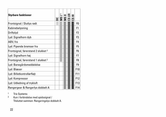
Styrbare funktioner
DC
MS
I 1
MS
IICS
I/II
CS II
I
Frontsignal/Slutlysrødt F0
Kabinebelysning F1
Driftslyd F2
Lyd:Signalhorndyb F3
ABV,fra F4
Lyd:Pipendebremserfra F5
Frontsignal,førerstand2slukket2 F6
Lyd:Signalhornhøj F7
Frontsignal,førerstand1slukket2 F8
Lyd:Banegårdsmeddelelse F9
Lyd:Blæser F10
Lyd:Billetkontrollørfløjt F11
Lyd:Kompressor F12
Lyd:Udledningaftrykluft F13
Rangergear&RangerlysdobbeltA F14
1 TrixSystems2 Kun i forbindelse med spidssignal / Tilsluttetsammen:RangeringslysdobbeltA.
23
* Indstillingernepålokomotivetsdekoderogpåstyreapparatetskalstemmeoverens,dafejlfunktionellersermulig.
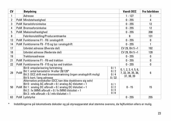
CV Betydning Værdi DCC Fra fabrikken1 Adresse 1 - 127 3 2 PoM Mindstehastighed 0-255 43 PoM Kørselsforsinkelse 0-255 124 PoM Bremseforsinkelse 0-255 125 PoM Maksimalhastighed 0-255 2088 Fabriksnulstilling/Producentmærke 8 131
13 PoM Funktionerne F1 - F8 i analogdrift 0-255 014 PoM FunktionerneF9-F15oglysianalogdrift 0-255 117 Udvidetadresse(Øverstedel) CV29,Bit5=1 19218 Udvidetadresse(Nederstedel) CV29,Bit5=1 12819 Traktionsadresse 0-255 021 PoM Funktionerne F1 - F8 ved traktion 0-255 022 PoM FunktionerneF9-F15oglysvedtraktion 0-255 0
29 PoM
Bit0:ompolariseringfartretning Bit1:antalkørselstrin14eller28/128* Bit2:DCCdriftmedbremsestrækning(ingenanalogdriftmulig) Bit5:kort/langadresse
0 / 1 0 / 2 0 / 4
0 / 32
0,1,2,3,4,5,6,7,32,34,35,36,37,38,39
6
50 PoM
Alternativeprotokoller(DCCkanikkedeaktiveresigselv) Bit0:analogACafbrudt=0/analogACtilsluttet=1 Bit1:analogDCafbrudt=0/analogDCtilsluttet=1 Bit2:fx(MM)afbrudt=0/fx(MM)tilsluttet=1 Bit3:mfxafbrudt=0/mfxtilsluttet=1
0 / 1 0 / 2 0 / 4 0 / 8
0-15 15
63 PoM Lydstyrke 0-255 255
24

25
26
27
40h
Gebr.Märklin&Cie.GmbHStuttgarterStraße55-5773033GöppingenGermanywww.trix.de
265671/1016/Sc1EfÄnderungen vorbehalten
©Gebr.Märklin&Cie.GmbHwww.maerklin.com/en/imprint.html
Duetodifferentlegalrequirementsregardingelectro-magneticcompatibility,thisitemmaybeusedintheUSAonlyafterseparatecertificationforFCCcom-plianceandanadjustmentifnecessary.UseintheUSAwithoutthiscertificationisnotpermittedandabsolvesusofanyliability.Ifyoushouldwantsuchcertificationtobedone,pleasecontactus–also due to the additional costs incurred for this.