Embed Size (px)
Citation preview
„Im Rahmen der hochschulweiten Open-Access-Strategie für die Zweitveröffentlichung identifiziert durch die Universitätsbibliothek Ilmenau.“
“Within the academic Open Access Strategy identified for deposition by Ilmenau University Library.”
„Dieser Beitrag ist mit Zustimmung des Rechteinhabers aufgrund einer (DFG-geförderten) Allianz- bzw. Nationallizenz frei zugänglich.“
„This publication is with permission of the rights owner freely accessible due to an Alliance licence and a national licence (funded by the DFG, German Research Foundation) respectively.”
Helbig, Marko; Dahlke, Katja; Hilger, Ingrid; Kmec, Martin; Sachs, Jürgen:
Design and test of an imaging system for UWB breast cancer detection
URN: urn:nbn:de:gbv:ilm1-2015210252
Published OpenAccess: January 2015
Original published in: Frequenz : journal of RF-engineering and telecommunications. - Berlin : De Gruyter (ISSN 2191-6349). - 66 (2012) 11/12, S. 387-394. DOI: 10.1515/freq-2012-0103 URL: http://dx.doi.org/10.1515/freq-2012-0103 [Visited: 2015-01-14]
brought to you by COREView metadata, citation and similar papers at core.ac.uk
provided by Digitale Bibliothek Thüringen
DOI 10.1515/freq-2012-0103 Frequenz 2012; 66(11-12): 387–394
Marko Helbig*, Katja Dahlke, Ingrid Hilger, Martin Kmec and Jürgen Sachs
Design and Test of an Imaging System for Uwb breast Cancer Detection
Abstract: Electromagnetic ultra-wideband (UWB) sensing and imaging provide perspectives for early-stage breast cancer detection. This paper deals with practical chal-lenges of real measurements. We present an experimental setup for breast phantom trials based on M-sequence radar technology and short active dipole antennas. It com-bines short impulse responses, appropriate fidelity and very small antenna dimension and allows array construc-tion with sufficient number of antennas around the breast. The basic approach and obtained imaging results are pre-sented. Furthermore, in this extended paper version con-tinuative development steps are described and measure-ment results reflecting specific performance aspects are discussed.
Keywords: UWB, M-sequence radar technology, breast cancer detection, short dipoles, breast phantoms
PACS® (2010). 84.40.-x
*Corresponding author: Marko Helbig: Institute for Information Technology, Ilmenau University of Technology, 98684 Ilmenau, Germany, E-mail: [email protected] Dahlke: Institute of Diagnostic and Interventional Radiology, Jena University Hospital, FSU Jena, 07747 Jena, GermanyIngrid Hilger: Institute of Diagnostic and Interventional Radiology, Jena University Hospital, FSU Jena, 07747 Jena, GermanyMartin Kmec: Institute for Information Technology, Ilmenau University of Technology, 98684 Ilmenau, GermanyJürgen Sachs: Institute for Information Technology, Ilmenau University of Technology, 98684 Ilmenau, Germany
1 IntroductionMicrowave sensing and imaging represent a promising alternative for early-stage screening diagnostics of breast cancer. This perspective results from the sensitivity of di-electric properties of human tissue at microwave frequen-cies to physiological signatures of clinical interest, espe-cially water content.
Numerous research groups are working in this field. Many groups deal with simulations and numerical models, while a limited number of groups perform
phantom measurements and first clinical trials [1–4]. The challenges which have to be overcome concerning real measurements are multifaceted and depend on the condi-tions of the measurement scenario. The developed strate-gies and measurement principles of microwave breast imaging can be classified by various characteristics: active vs. passive microwave imaging systems [5]; microwave tomography imaging [4] vs. UWB radar imaging [6, 7]; examination in prone vs. supine position and other differ-entiations more. This chapter deals exclusively with active microwave imaging based on UWB radar principle.
We present a preliminary experimental measuring setup for phantom trials in order to approximate patient measurements at prone examination position based on small dipole antennas [7] and we describe the progress in development towards an active antenna array for real in vivo measurements. Associated aspects (radar system, antenna properties, breast phantoms, data acquisition) are discussed and verified by measurements. Finally, we present imaging results which depict the functionality of the proposed approach.
2 Sensor technology
For our measurements we use M-sequence radar technol-ogy [8] developed at Ilmenau University of Technology. The stimulation signal (M-sequences) can be generated quite simply by high-speed digital shift registers. This pro-motes monolithic system integration by low cost semi- conductor technologies and can be used to build very flexible and time stable (low jitter and drift) UWB-sensor systems as described e.g. in [9].
This measurement approach is dealing with contin-uous wave signals which distribute the signal energy equally over time, thus, the signal magnitudes remain low. The reduced voltage exposure of the medium under test qualifies this technology for medical applications (spec-troscopy and imaging), e.g. for breast cancer detection.
The wanted impulse response of the scenario under test will be obtained by correlation between the received signal and the ideal M-sequence in the receiver. For the described measurements we use a base band MIMO
Bereitgestellt von | Universitätsbibliothek IlmenauAngemeldet
Heruntergeladen am | 14.01.15 16:31
388 M. Helbig et al., Design and Test of an Imaging System for Uwb Breast Cancer Detection
system (bandwidth 9 GHz) containing 2 transmitter (Tx) and 4 receiver (Rx).
3 Antennas and antenna arrayThe efficient penetration of the electromagnetic waves into the material under test and the spatially highly re-solved registration of the reflected signals are crucial tasks of the measurement setup. But from our point of view, in this regard efficiency is not only a matter of radiation efficiency or antenna return loss, respectively. An effi-cient antenna array design concerning biomedical UWB imaging comprises also shape and duration of signal im-pulses, angle dependency of the impulse characteristics (fidelity) and physical dimensions of the antenna. These interacting parameters are hard to accommodate to each other within one antenna design [10]. Generally, compro-mise solutions have to be found considering the condi-tions of the envisaged measurement scenario.
3.1 Small dipoles
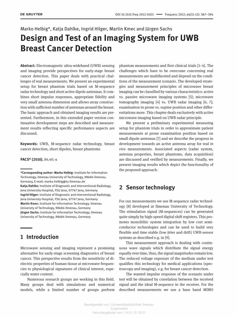
In this paper we pursue the objective of very small antenna dimension, short impulse responses and an application in direct or quasi direct contact to the breast skin. Short in-terfacial dipoles seem to represent a promising antenna structure to fulfill these specifications. Therefore, we in-vestigate the usability of small bow-ties implemented on Rogers RO4003C™ substrate (0.5 mm) using PCB technol-ogy. Their dimensions are 8 mm × 3 mm as shown in Fig. 1.
The dipoles have to be differentially fed. The balanced feeding is realized by customer designed differential am-
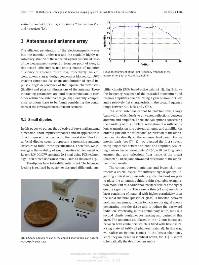
plifier circuits (SiGe based active baluns) [11]. Fig. 2 shows the frequency response of the cascaded transmitter and receiver amplifiers demonstrating a gain of around 30 dB and a relatively flat characteristic in the broad frequency range between 500 MHz and 7 GHz.
The short antennas cannot be matched over a large bandwidth, which leads to unwanted reflections between antenna and amplifier. There are two options concerning the handling of this problem: realization of a sufficiently long transmission line between antenna and amplifier (in order to gate out the reflections) or insertion of the ampli-fier circuits directly at the antenna feed point. On an interim basis (see [7], [12]) we pursued the first strategy using long cables between antenna and amplifier. Assum-ing a mean tissue permittivity ε′ ≤ 50, a 70 cm long cable ensured that any reflections from inside of the breast ( diameter ~ 10 cm) and unwanted reflections at the ampli-fier do not overlap.
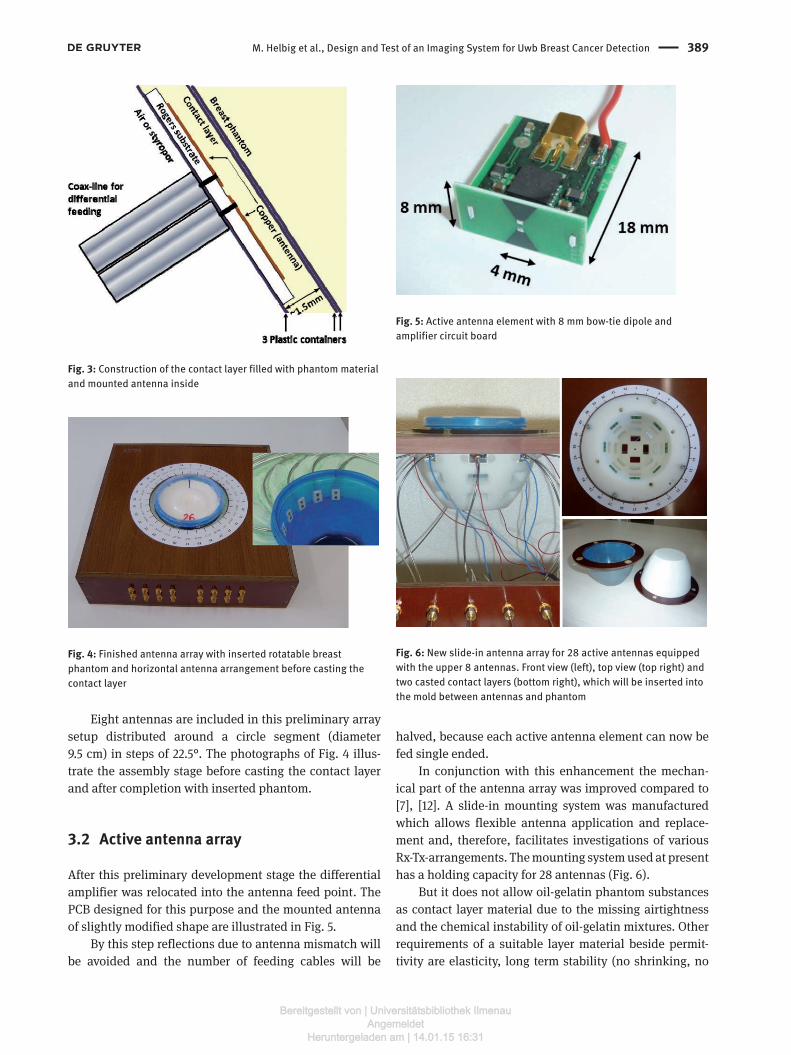
The contact between antennas and breast skin rep-resents a crucial aspect for sufficient signal quality. Re-garding clinical requirements (e.g. disinfection) we plan to place the antennas behind a thin cleanable examina-tion mold. But this additional interface reduces the signal quality significantly. Therefore, a thin (~2 mm) matching layer consisting of material with higher permittivity than the mold material (plastic or glass) is inserted between mold and antennas, in order to increase the signal energy penetrating into the tissue and to reduce the backward radiation. Practically, in this preliminary setup, we use a second plastic container for making and casing of this layer. The antennas are placed in the ~2 mm interspace between both containers which is filled with tissue mim-icking material (40% oil phantom material). In this way, we realize an optimal contact to the breast phantoms, since they are cased in identical bowls, too. Fig. 3 shows schematically the described assembly.
Fig. 1: Shape and dimension of the applied short dipoles on Rogers RO4003C™ substrate
Fig. 2: Measurement of the joint frequency response of the transmission path of Rx and Tx amplifier
Bereitgestellt von | Universitätsbibliothek IlmenauAngemeldet
Heruntergeladen am | 14.01.15 16:31
M. Helbig et al., Design and Test of an Imaging System for Uwb Breast Cancer Detection 389
Eight antennas are included in this preliminary array setup distributed around a circle segment (diameter 9.5 cm) in steps of 22.5°. The photographs of Fig. 4 illus-trate the assembly stage before casting the contact layer and after completion with inserted phantom.
3.2 Active antenna array
After this preliminary development stage the differential amplifier was relocated into the antenna feed point. The PCB designed for this purpose and the mounted antenna of slightly modified shape are illustrated in Fig. 5.
By this step reflections due to antenna mismatch will be avoided and the number of feeding cables will be
halved, because each active antenna element can now be fed single ended.
In conjunction with this enhancement the mechan-ical part of the antenna array was improved compared to [7], [12]. A slide-in mounting system was manufactured which allows flexible antenna application and replace-ment and, therefore, facilitates investigations of various Rx-Tx-arrangements. The mounting system used at present has a holding capacity for 28 antennas (Fig. 6).
But it does not allow oil-gelatin phantom substances as contact layer material due to the missing airtightness and the chemical instability of oil-gelatin mixtures. Other requirements of a suitable layer material beside permit-tivity are elasticity, long term stability (no shrinking, no
Fig. 3: Construction of the contact layer filled with phantom material and mounted antenna inside
Fig. 4: Finished antenna array with inserted rotatable breast phantom and horizontal antenna arrangement before casting the contact layer
Fig. 5: Active antenna element with 8 mm bow-tie dipole and amplifier circuit board
Fig. 6: New slide-in antenna array for 28 active antennas equipped with the upper 8 antennas. Front view (left), top view (top right) and two casted contact layers (bottom right), which will be inserted into the mold between antennas and phantom
Bereitgestellt von | Universitätsbibliothek IlmenauAngemeldet
Heruntergeladen am | 14.01.15 16:31
390 M. Helbig et al., Design and Test of an Imaging System for Uwb Breast Cancer Detection
drying out), and preferably manageable conditions of manufacture and dielectric property adjustment for re-search purposes. Therefore, we investigate polymer- powder composites, where dielectric powders (e.g. carbon meal or barium titanate powder, see Fig. 6) will be admixed to silicone rubber.
3.3 Performance assessment of the measurement setup
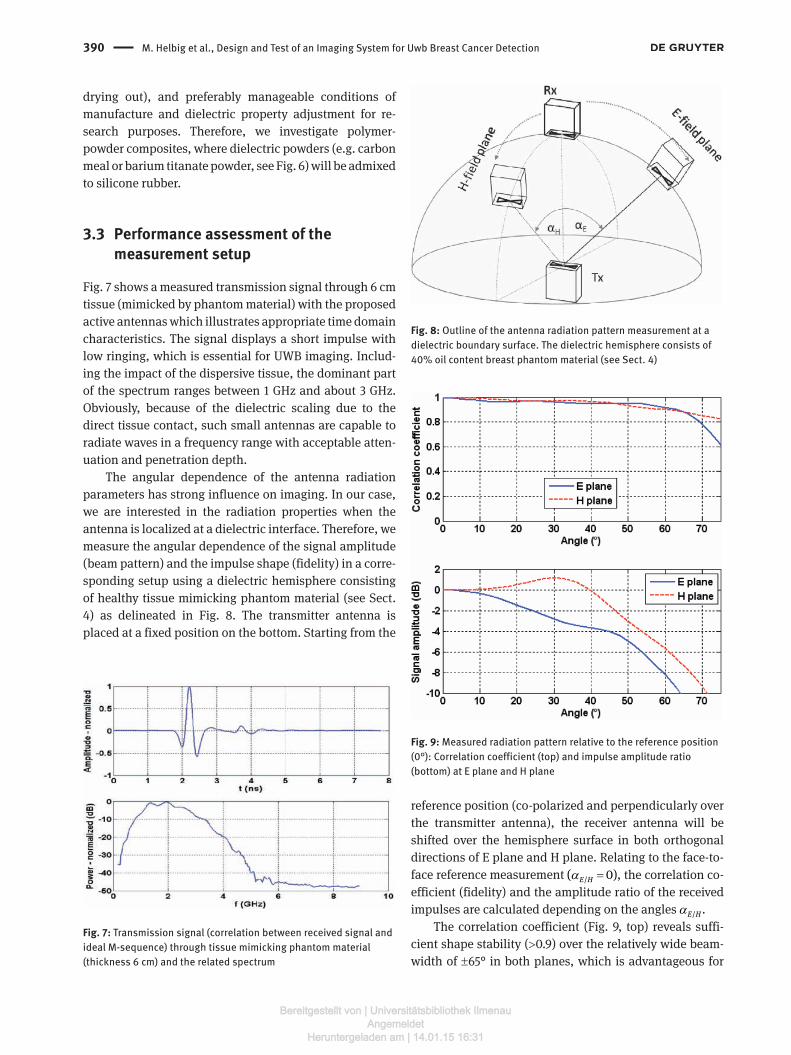
Fig. 7 shows a measured transmission signal through 6 cm tissue (mimicked by phantom material) with the proposed active antennas which illustrates appropriate time domain characteristics. The signal displays a short impulse with low ringing, which is essential for UWB imaging. Includ-ing the impact of the dispersive tissue, the dominant part of the spectrum ranges between 1 GHz and about 3 GHz. Obviously, because of the dielectric scaling due to the direct tissue contact, such small antennas are capable to radiate waves in a frequency range with acceptable atten-uation and penetration depth.
The angular dependence of the antenna radiation parameters has strong influence on imaging. In our case, we are interested in the radiation properties when the antenna is localized at a dielectric interface. Therefore, we measure the angular dependence of the signal amplitude (beam pattern) and the impulse shape (fidelity) in a corre-sponding setup using a dielectric hemisphere consisting of healthy tissue mimicking phantom material (see Sect. 4) as delineated in Fig. 8. The transmitter antenna is placed at a fixed position on the bottom. Starting from the
reference position (co-polarized and perpendicularly over the transmitter antenna), the receiver antenna will be shifted over the hemisphere surface in both orthogonal directions of E plane and H plane. Relating to the face-to-face reference measurement α =/( 0)E H , the correlation co-efficient (fidelity) and the amplitude ratio of the received impulses are calculated depending on the angles α /E H .
The correlation coefficient (Fig. 9, top) reveals suffi-cient shape stability (>0.9) over the relatively wide beam-width of ±65° in both planes, which is advantageous for
Fig. 7: Transmission signal (correlation between received signal and ideal M-sequence) through tissue mimicking phantom material (thickness 6 cm) and the related spectrum
Fig. 8: Outline of the antenna radiation pattern measurement at a dielectric boundary surface. The dielectric hemisphere consists of 40% oil content breast phantom material (see Sect. 4)
Fig. 9: Measured radiation pattern relative to the reference position (0°): Correlation coefficient (top) and impulse amplitude ratio (bottom) at E plane and H plane
Bereitgestellt von | Universitätsbibliothek IlmenauAngemeldet
Heruntergeladen am | 14.01.15 16:31
M. Helbig et al., Design and Test of an Imaging System for Uwb Breast Cancer Detection 391
de-convolution and super resolution tasks. However, the amplitude patterns of both planes vary. The characteristic of H plane turn out to be broader than that of E plane. Ad-ditionally, the impulse magnitude at the H plane reaches its maximum around 30° while at the E plane the refer-ence represents the maximum position (Fig. 9, bottom).
The following practical conclusions regarding differ-ent antenna arrangements and the corresponding resolu-tion can be drawn from these results. Assuming a circular antenna array and a de-central located tumor, the ex-pected resolution depicting this tumor in the image using a radial antenna arrangement at H plane should be better because more channels contribute to the imaging with valuable signal intensity than arranged in the orthogonal direction. One consequence of this knowledge can be to de-convolve the radiation pattern from the measured data similarly to the correction of path dependent attenuation. As noise will also be amplified in this way, the focal point specific exclusion of inappropriate channels can be an alternative strategy. This means that all channels with too wide angle between antenna boresight and image point will be excluded from the beamformer (1) depending on the point to be imaged (focal point).
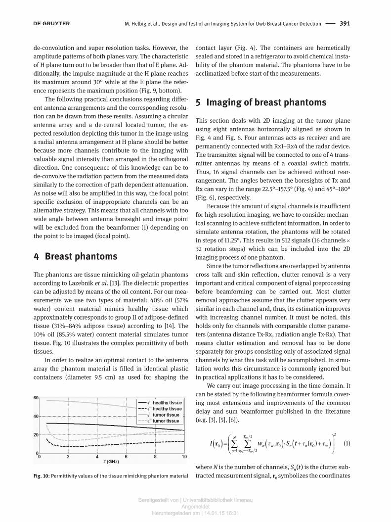
4 Breast phantomsThe phantoms are tissue mimicking oil-gelatin phantoms according to Lazebnik et al. [13]. The dielectric properties can be adjusted by means of the oil content. For our mea-surements we use two types of material: 40% oil (57% water) content material mimics healthy tissue which approximately corresponds to group II of adipose-defined tissue (31%–84% adipose tissue) according to [14]. The 10% oil (85.5% water) content material simulates tumor tissue. Fig. 10 illustrates the complex permittivity of both tissues.
In order to realize an optimal contact to the antenna array the phantom material is filled in identical plastic containers (diameter 9.5 cm) as used for shaping the
contact layer (Fig. 4). The containers are hermetically sealed and stored in a refrigerator to avoid chemical insta-bility of the phantom material. The phantoms have to be acclimatized before start of the measurements.
5 Imaging of breast phantomsThis section deals with 2D imaging at the tumor plane using eight antennas horizontally aligned as shown in Fig. 4 and Fig. 6. Four antennas acts as receiver and are permanently connected with Rx1–Rx4 of the radar device. The transmitter signal will be connected to one of 4 trans-mitter antennas by means of a coaxial switch matrix. Thus, 16 signal channels can be achieved without rear-rangement. The angles between the boresights of Tx and Rx can vary in the range 22.5°–157.5° (Fig. 4) and 45°–180° (Fig. 6), respectively.
Because this amount of signal channels is insufficient for high resolution imaging, we have to consider mechan-ical scanning to achieve sufficient information. In order to simulate antenna rotation, the phantoms will be rotated in steps of 11.25°. This results in 512 signals (16 channels × 32 rotation steps) which can be included into the 2D imaging process of one phantom.
Since the tumor reflections are overlapped by antenna cross talk and skin reflection, clutter removal is a very important and critical component of signal preprocessing before beamforming can be carried out. Most clutter removal approaches assume that the clutter appears very similar in each channel and, thus, its estimation improves with increasing channel number. It must be noted, this holds only for channels with comparable clutter parame-ters (antenna distance Tx-Rx, radiation angle Tx-Rx). That means clutter estimation and removal has to be done separately for groups consisting only of associated signal channels by what this task will be accomplished. In simu-lation works this circumstance is commonly ignored but in practical applications it has to be considered.
We carry out image processing in the time domain. It can be stated by the following beamformer formula cover-ing most extensions and improvements of the common delay and sum beamformer published in the literature (e.g. [3], [5], [6]).
( ) ( ) ( )τ
τ τ τ
= =−
= ⋅ + + ∑ ∑
22
0 0 01 2
, ( )TN w
n w n n wn TW w
I w S tr r r (1)
where N is the number of channels, ( )nS t is the clutter sub-tracted measurement signal, 0r symbolizes the coordinates Fig. 10: Permittivity values of the tissue mimicking phantom material
Bereitgestellt von | Universitätsbibliothek IlmenauAngemeldet
Heruntergeladen am | 14.01.15 16:31
392 M. Helbig et al., Design and Test of an Imaging System for Uwb Breast Cancer Detection
of the focal point, τ 0( )n r is the focal point dependent time delay of channel n, τ 0( , )n ww r is a FIR filter to equalize path dependent dispersion and attenuation (which can be in the simplest case only a weight coefficient) and 0( )I r is the back scattered energy which has to be mapped over all focal points.
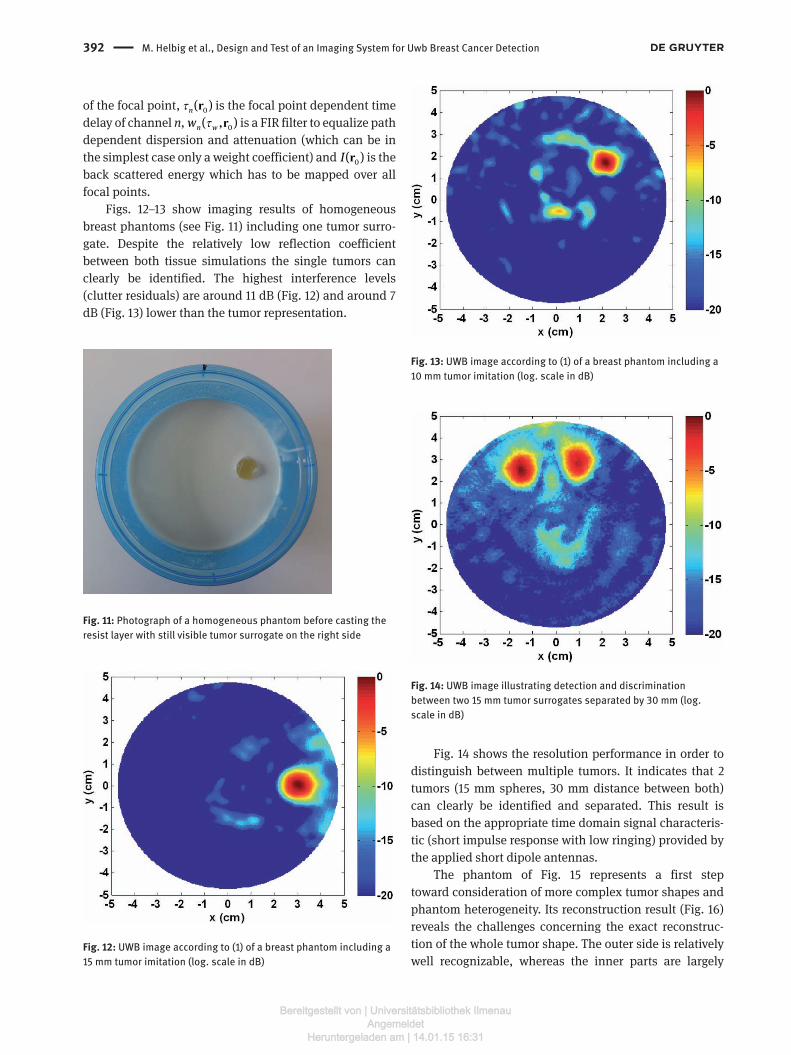
Figs. 12–13 show imaging results of homogeneous breast phantoms (see Fig. 11) including one tumor surro-gate. Despite the relatively low reflection coefficient between both tissue simulations the single tumors can clearly be identified. The highest interference levels (clutter residuals) are around 11 dB (Fig. 12) and around 7 dB (Fig. 13) lower than the tumor representation.
Fig. 14 shows the resolution performance in order to distinguish between multiple tumors. It indicates that 2 tumors (15 mm spheres, 30 mm distance between both) can clearly be identified and separated. This result is based on the appropriate time domain signal characteris-tic (short impulse response with low ringing) provided by the applied short dipole antennas.
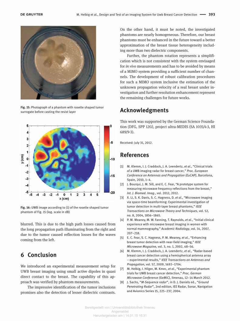
The phantom of Fig. 15 represents a first step toward consideration of more complex tumor shapes and phantom heterogeneity. Its reconstruction result (Fig. 16) reveals the challenges concerning the exact reconstruc-tion of the whole tumor shape. The outer side is relatively well recognizable, whereas the inner parts are largely
Fig. 11: Photograph of a homogeneous phantom before casting the resist layer with still visible tumor surrogate on the right side
Fig. 12: UWB image according to (1) of a breast phantom including a 15 mm tumor imitation (log. scale in dB)
Fig. 13: UWB image according to (1) of a breast phantom including a 10 mm tumor imitation (log. scale in dB)
Fig. 14: UWB image illustrating detection and discrimination between two 15 mm tumor surrogates separated by 30 mm (log. scale in dB)
Bereitgestellt von | Universitätsbibliothek IlmenauAngemeldet
Heruntergeladen am | 14.01.15 16:31
M. Helbig et al., Design and Test of an Imaging System for Uwb Breast Cancer Detection 393
blurred. This is due to the high path losses caused from the long propagation path illuminating from the right and due to the tumor caused reflection losses for the waves coming from the left.
6 ConclusionWe introduced an experimental measurement setup for UWB breast imaging using small active dipoles in quasi direct contact to the breast. The capability of this ap-proach was verified by phantom measurements.
The impressive identification of the tumor inclusions promises also the detection of lesser dielectric contrasts.
On the other hand, it must be noted, the investigated phantoms are nearly homogeneous. Therefore, our breast phantoms must be enhanced in the future toward a better approximation of the breast tissue heterogeneity includ-ing more than two dielectric components.
Further, the phantom rotation represents a simplifi-cation which is not consistent with the system envisaged for in vivo measurements and has to be avoided by means of a MIMO system providing a sufficient number of chan-nels. The development of robust calibration procedures for such a MIMO system inclusive the estimation of the unknown propagation velocity of a real breast under in-vestigation and further resolution enhancement represent the remaining challenges for future works.
AcknowledgmentsThis work was supported by the German Science Founda-tion (DFG, SPP 1202, project ultra-MEDIS (SA 1035/4-3, HI 689/9-3).
Received: July 31, 2012.
References[1] M. Klemm, I. J. Craddock, J. A. Leendertz, et al., “Clinical trials
of a UWB imaging radar for breast cancer,” Proc. European Conference on Antennas and Propagation (EuCAP), Barcelona, Spain, 2010, 1–4.
[2] J. Bourqui, J. M. Sill, and E. C. Fear, “A prototype system for measuring microwave frequency reflections from the breast,” Int. J. Biomed. Imag., vol. 2012, 2012.
[3] X. Li, S. K. Davis, S. C. Hagness, D. et al., “Microwave imaging via space-time beamforming: Experimental investigation of tumor detection in multi-layer breast phantoms,” IEEE Transactions on Microwave Theory and Techniques, vol. 52, no. 8, 2004, 1856–1865.
[4] P. M. Meaney, M. W. Fanning, T. Raynolds, et al., “Initial clinical experience with microwave breast imaging in women with normal mammography,” Academic Radiology, vol. 14, 2007, 207–218.
[5] E. C. Fear, S. C. Hagness, P. M. Meaney, et al., “Enhancing breast tumor detection with near-field imaging,” IEEE Microwave Magazine, vol. 3, no. 1, 2002, 48–56.
[6] M. Klemm, I. J. Craddock, J. A. Leendertz, et al., “Radar-based breast cancer detection using a hemispherical antenna array – experimental results,” IEEE Transactions on Antennas and Propagation, vol. 57, 2009, 1692–1704.
[7] M. Helbig, I. Hilger, M. Kmec, et al., “Experimental phantom trials for UWB breast cancer detection,” Proc. German Microwave Conference (GeMiC), Ilmenau, 12–14 March 2012.
[8] J. Sachs, “M-Sequence radar”, in D. J. Daniels ed., “Ground Penetrating Radar”, 2nd edition, IEE Radar, Sonar, Navigation and Avionics Series 15, 225–237, 2004.
Fig. 15: Photograph of a phantom with rosette shaped tumor surrogate before casting the resist layer
Fig. 16: UWB image according to (1) of the rosette shaped tumor phantom of Fig. 15 (log. scale in dB)
Bereitgestellt von | Universitätsbibliothek IlmenauAngemeldet
Heruntergeladen am | 14.01.15 16:31

394 M. Helbig et al., Design and Test of an Imaging System for Uwb Breast Cancer Detection
[9] J. Sachs, “Handbook of Ultra-Wideband Short-Range Sensing: Theory, Sensors, Applications”, Wiley-VCH Verlag, 2012.
[10] M. A. Hein, C. Geyer, M. Helbig, et al., “Antennas for Ultra-Wideband Medical Sensor Systems,“ Proc. European Conference on Antennas and Propagation (EuCAP), Berlin, 2009, 1868–1871.
[11] M. Kmec, M. Helbig, J. Sachs, et al., “Integrated ultra-wideband hardware for MIMO sensing using pn-sequence approach,” Proc. Intern. Conference on Ultra-Wideband (ICUWB), Syracuse, USA, 17–20 Sept. 2012, 333–337.
[12] M. Helbig, M. Kmec, J. Sachs, et al., “Aspects of Antenna Array Configuration for UWB Breast Imaging,” Proc. European
Conference on Antennas and Propagation (EuCAP), Prague, 26–30 March 2012, 1737–1741.
[13] M. Lazebnik, E. L. Madsen, G. R. Frank, and S. C. Hagness, “Tissue-mimicking phantom materials for narrowband and ultrawideband microwave applications,” Physics in Medicine and Biology, vol. 50, 2005, 4245–4258.
[14] M. Lazebnik, D. Popovic, L. McCartney, et al., “A large scale of the ultrawideband microwave dielectric properties of normal, benign and malignant breast tissues obtained from cancer surgeries,” Physics in Medicine and Biology, vol. 52, 2007, 6093–6115.
Bereitgestellt von | Universitätsbibliothek IlmenauAngemeldet
Heruntergeladen am | 14.01.15 16:31