Embed Size (px)
Citation preview

DE|EN 04|2014
Locking Assemblies
ECOLOC

Anderen vertrauen Sie, bei uns sind Sie sicher!
ECOLOC you can trust –others you can’t be sure!
Immer da, wo mit „spitzer Feder” gerechnet werden muss, bietet RINGFEDER POWER TRANSMISSION mit der neuen Produktlinie ECOLOC eine effiziente Alternative. So wird es möglich, auch im Bereich der Standard-Massenanwendungen RINGFEDER POWER TRANSMISSION - Markenware kostengünstig einzusetzen. Produkt- und ferti-gungsoptimierte Prozesse gewährleisten ein hohes Maß an Wirtschaftlichkeit.
RINGFEDER POWER TRANSMISSION, always there when precise calculations have to be made, now offers a new Locking Assembly with the launch of its ECOLOC product line. Improved manufacturing processes guarantee competitive pricing, making it possible to produce a low cost RINGFEDER POWER TRANSMISSION branded product which is suitable for most applications.
2
Produkte · Products
Seite / Page 04 7061 ECOLOC
Seite / Page 06 7003 ECOLOC
Seite / Page 08 7004 ECOLOC
Seite / Page 10 7005 ECOLOC
Seite / Page 14 7006 ECOLOC
Seite / Page 16 7007 ECOLOC
Seite / Page 18 7110 ECOLOC
Alle technischen Daten und Hin weise sind unverbindlich. Rechts ansprüche können daraus nicht abgeleitet werden. Der Anwender ist grundsätzlich verpflichtet zu prü-fen, ob die dargestellten Produkte seinen Anforderungen genügen. Änderungen, die dem technischen Fortschritt dienen, behalten wir uns jederzeit vor. Mit Erscheinen dieses Kataloges werden alle älteren Prospekte und Fragebögen zu den gezeigten Produkten ungültig.
All technical details and information are non-binding and cannot be used as a basis for legal claims. The user is obligated to determine whether the represented products meet his requirements. We reserve the right at all times to carry out modifications in the interests of technical progress. Upon the issue of this catalogue all previous brochures and questionnaires on the products displayed are no longer valid.
3

Spannsätze • Locking Assemblies
7061 ECOLOC
Weitere Größen auf Anfrage / Other sizes on requestAusführung: Stahl / Material: Steel
Selbstzentrierende, kostengünstige 2-teilige Spannsätze für mittlere Dreh momente. Bei der Montage erfolgt eine geringe Axial-verschiebung der Nabe. Aufgrund der geringen Schraubenzahl sind Kosten ein-spar ungen bei der Montage gewährleistet. Zur Demontage sind nur wenige Abdrück-schrauben nötig. Auch für sehr kleine Wellendurchmesser verfügbar.
7061 ECOLOC
Self-centering, cost-efficient 2-piece Locking Assem blies for medium torques. During mount ing, minor axial displacement of the hub occurs. Due to the small number of screws, cost savings during mounting are ensured. For disassembly only few release screws are required. Also availabe for very small shaft diameters.
7061 ECOLOC
Technische HinweiseTechnical information
Oberflächen / Surface finishes Für Welle und Nabenbohrung For shafts and hub bores Ra = 1,6 µm
Toleranzen / Tolerances Wir empfehlen folgende Einbautoleranzen We recommend the following mounting tolerances Welle / Shaft: h8 · Nabe / Hub: H8
Typ / Type d x D
7061 ECOLOC 6 x 16
Bestellbeispiel · Ordering example:
Metrische Abmessungen Schrauben
Metric dimensions Screws
ISO 4762-12.9
d x D L L1 T or Fax TA pW pN nSc DG
mm Nm kN Nm N/mm2
6 x 16 13,5 11 6 2 1,2 150 55 3 x M 2,5
6,35 x 16 13,5 11 6 2 1,2 140 55 3 x M 2,5
7 x 17 13,5 11 8 2 1,2 125 55 3 x M 2,5
8 x 18 13,5 11 10 2,5 1,2 110 50 3 x M 2,5
9 x 20 15,5 13 15 3 1,2 120 55 4 x M 2,5
9,53 x 20 15,5 13 15 3 1,2 110 55 4 x M 2,5
10 x 20 15,5 13 15 3 1,2 110 55 4 x M 2,5
11 x 22 15,5 13 18 3 1,2 100 50 4 x M 2,5
12 x 22 15,5 13 20 3 1,2 90 50 4 x M 2,5
14 x 26 20 17 35 5 2,1 105 55 4 x M 3
15 x 28 20 17 40 5 2,1 100 50 4 x M 3
16 x 32 21 17 70 8 4,9 130 65 4 x M 4
17 x 35 25 21 75 8 4,9 120 60 4 x M 4
18 x 35 25 21 80 8 4,9 115 60 4 x M 4
19 x 35 25 21 85 8 4,9 110 60 4 x M 4
20 x 38 26 21 150 15 9,7 140 75 4 x M 5
22 x 40 26 21 160 14 17 130 70 4 x M 6
24 x 47 32 26 250 20 17 140 75 4 x M 6
25 x 47 32 26 260 20 17 135 75 4 x M 6
25,4 x 47 32 26 265 20 17 130 75 4 x M 6
28 x 50 32 26 440 30 17 185 100 6 x M 6
30 x 55 32 26 470 30 17 175 95 6 x M 6
32 x 55 32 26 500 30 17 165 95 6 x M 6
35 x 60 37 29 730 40 17 165 95 8 x M 6
38 x 65 37 29 800 40 17 155 90 8 x M 6
40 x 65 37 29 840 40 17 145 90 8 x M 6
42 x 75 44 36 1,2 55 41 165 90 6 x M 8
45 x 75 44 36 1,3 55 41 155 90 6 x M 8
48 x 80 44 36 1,9 75 41 195 115 8 x M 8
50 x 80 44 36 1,9 75 41 185 115 8 x M 8
4

Erläuterungen / Explanations
d = Innendurchmesser/Inner ring diameter
D = Außendurchmesser/Outer diameter
L = Einbaulänge maximal/Overall width
L1 = Einbaulänge mind. (ohne Schrauben) Overall width (without screws)
T = Übertragbares Drehmoment bei angegebenem TA Transmissible torque at given TA
Fax = Übertragbare Axialkraft/Transmissible axial force
TA = Vorgegebenes Anzugsmoment der Spannschrauben/Max. tightened torque of the screws
pW = Flächenpressung auf der Welle bei angegebenem TA/Surface pressure on shaft at given TA
pN = Flächenpressung auf der Nabe bei angegebenem TA/Surface pressure on hub at given TA
nSc = Anzahl der Spannschrauben Quantity of locking screws
DG = Gewindedurchmesser/Thread
Locking Assemblies 7061 ECOLOC
LL1
d DInch Abmessungen Schrauben
Inch dimensions Screws
ISO 4762-12.9
d d x D L L1 T or Fax TA pW pN nSc DG
mm inch ft-lbs lbs ft-lbs psi
6 0.236 x 0.630 0.531 0.433 4,4 446 0.9 21.739 7.971 3 x M 2.5
6.35 0.250 x 0.630 0.531 0.433 4,4 446 0.9 20.290 7.971 3 x M 2.5
7 0.276 x 0.669 0.531 0.433 5,9 446 0.9 18.116 7.971 3 x M 2.5
8 0.315 x 0.709 0.531 0.433 7,4 558 0.9 15.942 7.246 3 x M 2.5
9 0.354 x 0.787 0.610 0.512 11,1 669 0.9 17.391 7.971 4 x M 2.5
9.53 0.375 x 0.787 0.610 0.512 11,1 669 0.9 110 55 4 x M 2.5
10 0.394 x 0.787 0.610 0.512 11,1 669 0.9 15.942 7.971 4 x M 2.5
11 0.433 x 0.866 0.610 0.512 13,3 669 0.9 14.493 7.246 4 x M 2.5
12 0.472 x 0.866 0.610 0.512 14,8 669 0.9 13.043 7.246 4 x M 2.5
14 0.551 x 1.024 0.787 0.669 25,8 1.116 1.5 15.217 7.971 4 x M 3
15 0.591 x 1.102 0.787 0.669 29,5 1.116 1.5 14.493 7.246 4 x M 3
16 0.630 x 1.260 0.827 0.669 51,6 1.785 3.6 18.841 9.420 4 x M 4
17 0.669 x 1.378 0.984 0.827 55,3 1.785 3.6 17.391 8.696 4 x M 4
18 0.709 x 1.378 0.984 0.827 59 1.785 3.6 16.667 8.696 4 x M 4
19 0.748 x 1.378 0.984 0.827 62,7 1.785 3.6 15.942 8.696 4 x M 4
20 0.787 x 1.496 1.024 0.827 110,6 3.347 7.2 20.290 10.870 4 x M 5
22 0.866 x 1.575 1.024 0.827 118 3.124 7.2 18.841 10.145 4 x M 5
24 0.945 x 1.850 1.260 1.024 184,4 4.462 12.5 20.290 10.870 4 x M 6
25 0.984 x 1.850 1.260 1.024 191,8 4.462 12.5 19.565 10.870 4 x M 6
25.4 1.000 x 1.850 1.260 1.024 195,5 4.462 12.5 18.841 10.870 4 x M 6
28 1.102 x 1.969 1.260 1.024 324,5 6.693 12.5 26.812 14.493 6 x M 6
30 1.181 x 2.165 1.260 1.024 346,7 6.693 12.5 25.362 13.768 6 x M 6
32 1.260 x 2.165 1.260 1.024 368,8 6.693 12.5 23.913 13.768 6 x M 6
35 1.378 x 2.362 1.457 1.142 538,4 8.925 12.5 23.913 13.768 8 x M 6
38 1.496 x 2.559 1.457 1.142 590,1 8.925 12.5 22.464 13.043 8 x M 6
40 1.575 x 2.559 1.457 1.142 619,6 8.925 12.5 21.014 13.043 8 x M 6
42 1.654 x 2.953 1.732 1.417 0,9 12.271 30.2 23.913 13.043 6 x M 8
45 1.772 x 2.953 1.732 1.417 1 12.271 30.2 22.464 13.043 6 x M 8
48 1.890 x 3.150 1.732 1.417 1,4 16.734 30.2 28.261 16.667 8 x M 8
50 1.969 x 3.150 1.732 1.417 1,4 16.734 30.2 26.812 16.667 8 x M 8
1 inch = 25,4 mm • 1 ft-lbs = 1,3558 Nm • 1 lbs = 4,4482 N • 1 psi = 0,0069 N/mm2
Weitere Größen auf Anfrage / Other sizes on requestAusführung: Stahl / Material: Steel
5

7003 ECOLOCSpannsätze · Locking Assemblies
Sind selbstzentrierende 2-teilige Low Cost Spann sätze, welche aufgrund des Schlitzes auch bei größeren Toleranzen eingesetzt werden können. Die Nabe verschiebt sich bei der Montage etwas Richtung Schrau-benkopf. Für die De montage sind nur wenige Abdrück schrauben nötig. Durch die optimierte Flanschgeometrie ist die Verformung des Flansches deutlich gerin-ger als bei handelsüblichen Produkten.
7003 ECOLOC
Technische Hinweise Technical information
Oberflächen / Surface finishes Für Welle und Nabenbohrung For shafts and hub bores Ra = 1,6 µm
Toleranzen / Tolerances Wir empfehlen folgende Einbautoleranzen We recommend the following mounting tolerances Welle / Shaft: h8 · Nabe / Hub: H8
Typ / Type d x D
7003 ECOLOC 24 x 50
Bestellbeispiel · Ordering example:
Weitere Größen auf Anfrage / Other sizes on requestAusführung: Stahl / Material: Steel
7003 ECOLOC
Self-centering, 2-piece low-cost Locking Assemblies, which can be used - due to the slit - also at larger tolerances. The hub slightly positions during mounting towards the screw head. For dis assembly only few release screws are required. Through opti-mised geometry of the flange, the deforma-tion of the flange is significantly lower than with standard products.
Metrische Abmessungen Schrauben
Metric dimensions Screws
ISO 4762-12.9
d x D L L1 L3 T or Fax TA pW pN nSc DG
mm Nm kN Nm N/mm2
19 x 47 34 28 17 355 31 14 280 120 5 x M 620 x 47 34 28 17 360 33 14 280 120 5 x M 622 x 47 34 28 17 400 33 14 260 125 5 x M 624 x 50 34 28 17 440 36 14 245 120 6 x M 625 x 50 34 28 17 560 36 14 280 140 6 x M 628 x 55 34 28 17 625 36 14 250 130 6 x M 630 x 55 34 28 17 650 36 14 235 130 6 x M 632 x 60 34 28 17 950 50 14 290 150 8 x M 635 x 60 34 28 17 1.050 50 14 290 150 8 x M 638 x 65 34 28 17 1.140 50 14 250 145 8 x M 640 x 65 34 28 17 1.200 50 14 230 145 8 x M 642 x 75 41 33 20 2.030 70 35 305 170 7 x M 845 x 75 41 33 20 2.180 70 35 285 170 7 x M 848 x 80 41 33 20 2.330 80 35 270 160 7 x M 850 x 80 41 33 20 2.430 85 35 260 160 7 x M 855 x 85 41 33 20 3.050 100 35 270 175 8 x M 860 x 90 41 33 20 3.350 100 35 245 165 8 x M 865 x 95 41 33 20 4.080 110 35 255 175 9 x M 870 x 110 50 40 24 6.280 160 70 280 180 8 x M 1075 x 115 50 40 24 6.680 160 70 260 170 8 x M 1080 x 120 50 40 24 7.130 160 70 250 170 8 x M 1085 x 125 50 40 24 8.750 180 70 260 180 9 x M 1090 x 130 50 40 24 9.080 180 70 250 170 9 x M 1095 x 135 50 40 24 10.580 200 70 260 180 10 x M 10
100 x 145 56 44 26 13.380 240 125 270 190 8 x M 12110 x 155 56 44 26 14.580 240 125 240 180 8 x M 12120 x 165 56 44 26 17.880 250 125 250 180 9 x M 12130 x 180 64 52 34 25.950 350 125 240 170 12 x M 12140 x 190 68 54 34 26.950 350 190 210 150 9 x M 14150 x 200 68 54 34 32.950 400 190 230 170 10 x M 14160 x 210 68 54 34 37.950 450 190 230 170 11 x M 14170 x 225 78 64 44 44.950 500 190 180 130 12 x M 14180 x 235 78 64 44 46.950 500 190 170 130 12 x M 14190 x 250 78 64 44 64.059 607 190 141 146 15 x M 14200 x 260 78 64 44 67.430 607 190 134 141 15 x M 14220 x 285 88 72 50 82.211 710 290 130 132 12 x M 16240 x 305 88 72 50 112.106 848 290 149 154 15 x M 16260 x 325 88 72 50 145.737 1.017 290 165 174 18 x M 16280 x 355 102 84 60 168.715 1.094 400 139 143 16 x M 18300 x 375 102 84 60 203.362 1.230 400 146 152 18 x M 18320 x 405 121 101 74 287.020 1.627 580 150 151 18 x M 20340 x 425 121 101 74 355.785 1.899 580 165 168 21 x M 20360 x 455 137 115 86 395.461 1.994 780 142 142 18 x M 22380 x 475 137 115 86 487.003 2.326 780 157 158 21 x M 22400 x 495 137 115 86 512.635 2.326 780 150 152 21 x M 22
6
LL1
L3
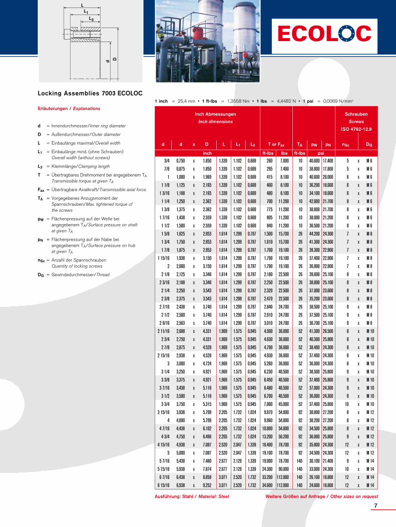
DdErläuterungen / Explanations
d = Innendurchmesser/Inner ring diameter
D = Außendurchmesser/Outer diameter
L = Einbaulänge maximal/Overall width
L1 = Einbaulänge mind. (ohne Schrauben) Overall width (without screws)
L3 = Klemmlänge/Clamping length
T = Übertragbares Drehmoment bei angegebenem TA Transmissible torque at given TA
Fax = Übertragbare Axialkraft/Transmissible axial force
TA = Vorgegebenes Anzugsmoment der Spannschrauben/Max. tightened torque of the screws
pW = Flächenpressung auf der Welle bei angegebenem TA/Surface pressure on shaft at given TA
pN = Flächenpressung auf der Nabe bei angegebenem TA/Surface pressure on hub at given TA
nSc = Anzahl der Spannschrauben Quantity of locking screws
DG = Gewindedurchmesser/Thread
1 inch = 25,4 mm • 1 ft-lbs = 1,3558 Nm • 1 lbs = 4,4482 N • 1 psi = 0,0069 N/mm2
Locking Assemblies 7003 ECOLOC
Ausführung: Stahl / Material: Steel Weitere Größen auf Anfrage / Other sizes on request
Inch Abmessungen Schrauben
Inch dimensions Screws
ISO 4762-12.9
d d x D L L1 L3 T or Fax TA pW pN nSc DG
inch ft-lbs lbs ft-lbs psi
3/4 0,750 x 1.850 1.339 1.102 0.669 260 7.000 10 40.600 17.400 5 x M 6
7/8 0,875 x 1.850 1.339 1.102 0.669 295 7.400 10 38.800 17.800 5 x M 6
1 1,000 x 1.969 1.339 1.102 0.669 415 8.100 10 40.600 20.000 6 x M 6
1 1/8 1,125 x 2.165 1.339 1.102 0.669 460 8.100 10 36.200 18.600 6 x M 6
1 3/16 1,188 x 2.165 1.339 1.102 0.669 480 8.100 10 34.100 18.600 6 x M 6
1 1/4 1,250 x 2.362 1.339 1.102 0.669 700 11.200 10 42.000 21.700 8 x M 6
1 3/8 1,375 x 2.362 1.339 1.102 0.669 775 11.200 10 38.800 21.700 8 x M 6
1 7/16 1,438 x 2.559 1.339 1.102 0.669 805 11.200 10 38.000 21.200 8 x M 6
1 1/2 1,500 x 2.559 1.339 1.102 0.669 840 11.200 10 36.500 21.200 8 x M 6
1 5/8 1,625 x 2.953 1.614 1.299 0.787 1.500 15.700 26 44.200 24.300 7 x M 8
1 3/4 1,750 x 2.953 1.614 1.299 0.787 1.610 15.700 26 41.300 24.300 7 x M 8
1 7/8 1,875 x 2.953 1.614 1.299 0.787 1.700 19.100 26 39.300 22.900 7 x M 8
1 15/16 1,938 x 3.150 1.614 1.299 0.787 1.790 19.100 26 37.400 22.900 7 x M 8
2 2,000 x 3.150 1.614 1.299 0.787 1.790 19.100 26 36.800 22.900 7 x M 8
2 1/8 2,125 x 3.346 1.614 1.299 0.787 2.180 22.500 26 39.600 25.100 8 x M 8
2 3/16 2,188 x 3.346 1.614 1.299 0.787 2.250 22.500 26 38.800 25.100 8 x M 8
2 1/4 2,250 x 3.543 1.614 1.299 0.787 2.320 22.500 26 37.000 23.600 8 x M 8
2 3/8 2,375 x 3.543 1.614 1.299 0.787 2.470 22.500 26 35.200 23.600 8 x M 8
2 7/16 2,438 x 3.740 1.614 1.299 0.787 2.840 24.700 26 38.500 25.100 9 x M 8
2 1/2 2,500 x 3.740 1.614 1.299 0.787 2.910 24.700 26 37.500 25.100 9 x M 8
2 9/16 2,563 x 3.740 1.614 1.299 0.787 3.010 24.700 26 36.700 25.100 9 x M 8
2 11/16 2,688 x 4.331 1.969 1.575 0.945 4.500 36.000 52 41.300 26.500 8 x M 10
2 3/4 2,750 x 4.331 1.969 1.575 0.945 4.630 36.000 52 40.300 25.800 8 x M 10
2 7/8 2,875 x 4.528 1.969 1.575 0.945 4.790 36.000 52 38.400 24.300 8 x M 10
2 15/16 2,938 x 4.528 1.969 1.575 0.945 4.930 36.000 52 37.400 24.300 8 x M 10
3 3,000 x 4.724 1.969 1.575 0.945 5.260 36.000 52 36.000 24.300 8 x M 10
3 1/4 3,250 x 4.921 1.969 1.575 0.945 6.230 40.500 52 38.500 25.800 9 x M 10
3 3/8 3,375 x 4.921 1.969 1.575 0.945 6.450 40.500 52 37.400 25.800 9 x M 10
3 7/16 3,438 x 5.118 1.969 1.575 0.945 6.480 40.500 52 37.000 24.300 9 x M 10
3 1/2 3,500 x 5.118 1.969 1.575 0.945 6.700 40.500 52 36.000 24.300 9 x M 10
3 3/4 3,750 x 5.315 1.969 1.575 0.945 7.800 45.000 52 37.400 25.800 10 x M 10
3 15/16 3,938 x 5.709 2.205 1.732 1.024 9.870 54.000 92 38.800 27.200 8 x M 12
4 4,000 x 5.709 2.205 1.732 1.024 9.960 54.000 92 38.200 27.200 8 x M 12
4 7/16 4,438 x 6.102 2.205 1.732 1.024 10.800 54.000 92 34.500 25.800 8 x M 12
4 3/4 4,750 x 6.496 2.205 1.732 1.024 13.200 56.200 92 36.000 25.800 9 x M 12
4 15/16 4,938 x 7.087 2.520 2.047 1.339 18.400 78.700 92 35.800 24.300 12 x M 12
5 5,000 x 7.087 2.520 2.047 1.339 19.100 78.700 92 34.500 24.300 12 x M 12
5 7/16 5,438 x 7.480 2.677 2.126 1.339 19.900 78.700 140 30.100 21.400 9 x M 14
5 15/16 5,938 x 7.874 2.677 2.126 1.339 24.300 90.000 140 33.000 24.300 10 x M 14
6 7/16 6,438 x 8.858 3.071 2.520 1.732 33.200 112.000 140 26.100 18.800 12 x M 14
6 15/16 6,938 x 9.252 3.071 2.520 1.732 34.600 112.000 140 24.600 18.800 12 x M 14
7
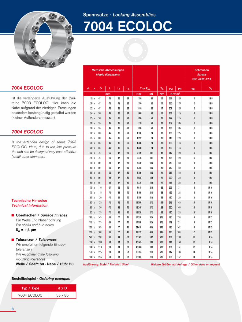
7004 ECOLOCSpannsätze · Locking Assemblies
Ist die verlängerte Ausführung der Bau-reihe 7003 ECOLOC. Hier kann die Nabe aufgrund der niedrigen Pressun gen besonders kostengünstig gestaltet werden (kleiner Außendurch messer).
7004 ECOLOC
Is the extended design of series 7003 ECOLOC. Here, due to the low pressure the hub can be designed very cost-effective (small outer diameter).
7004 ECOLOC
Technische HinweiseTechnical information
Oberflächen / Surface finishes Für Welle und Nabenbohrung For shafts and hub bores Ra = 1,6 µm
Toleranzen / Tolerances Wir empfehlen folgende Einbau- toleranzen We recommend the following mounting tolerances Welle / Shaft: h8 · Nabe / Hub: H8
Typ / Type d x D
7004 ECOLOC 55 x 85
Bestellbeispiel · Ordering example:
Weitere Größen auf Anfrage / Other sizes on requestAusführung: Stahl / Material: Steel
Metrische Abmessungen Schrauben
Metric dimensions Screws
ISO 4762-12.9
d x D L L1 L3 T or Fax TA pW pN nSc DG
mm Nm kN Nm N/mm2
19 x 47 45 39 26 530 56 17 298 120 6 M 6
20 x 47 45 39 26 550 56 17 283 120 6 M 6
22 x 47 45 39 26 610 56 17 257 120 6 M 6
24 x 50 45 39 26 660 56 17 236 115 6 M 6
25 x 50 45 39 26 690 56 17 227 115 6 M 6
28 x 55 45 39 26 770 56 17 202 105 6 M 6
30 x 55 45 39 26 830 56 17 190 105 6 M 6
32 x 60 45 39 26 1.180 74 17 235 125 8 M 6
35 x 60 45 39 26 1.295 74 17 216 126 8 M 6
38 x 65 45 39 26 1.400 74 17 200 116 8 M 6
40 x 65 45 39 26 1.480 74 17 190 116 8 M 6
42 x 75 55 47 30 2.120 101 41 212 120 6 M 8
45 x 75 55 47 30 2.270 101 41 198 120 6 M 8
48 x 80 55 47 30 3.230 135 41 250 150 8 M 8
50 x 80 55 47 30 3.365 135 41 240 150 8 M 8
55 x 85 55 47 30 3.700 135 41 216 140 8 M 8
60 x 90 55 47 30 4.035 135 41 200 135 8 M 8
65 x 95 55 47 30 4.370 135 41 183 125 8 M 8
70 x 110 67 62 40 7.615 218 83 206 131 8 M 10
75 x 115 72 62 40 8.160 218 83 192 126 8 M 10
80 x 120 72 62 40 8.700 218 83 180 120 8 M 10
85 x 125 72 62 40 11.560 272 83 212 145 10 M 10
90 x 130 72 62 40 12.240 272 83 200 140 10 M 10
95 x 135 72 62 40 12.920 272 83 190 135 10 M 10
100 x 145 89 77 46 16.270 325 145 190 130 8 M 12
110 x 155 89 77 46 17.900 325 145 171 121 8 M 12
120 x 165 89 77 46 24.410 405 145 196 142 10 M 12
130 x 180 89 77 46 31.735 488 145 220 160 12 M 12
140 x 190 98 84 51 35.502 507 210 188 139 10 M 14
150 x 200 98 84 51 45.645 609 210 211 158 12 M 14
160 x 210 98 84 51 48.688 609 210 198 151 12 M 14
170 x 225 98 84 51 60.353 710 210 217 164 14 M 14
180 x 235 98 84 51 63.903 710 210 205 157 14 M 14
8

D
d
LL1
L3
Erläuterungen / Explanations
d = Innendurchmesser/Inner ring diameter
D = Außendurchmesser/Outer diameter
L = Einbaulänge maximal/Overall width
L1 = Einbaulänge mind. (ohne Schrauben) Overall width (without screws)
L3 = Klemmlänge/Clamping length
T = Übertragbares Drehmoment bei angegebenem TA Transmissible torque at given TA
Fax = Übertragbare Axialkraft/Transmissible axial force
TA = Vorgegebenes Anzugsmoment der Spannschrauben/Max. tightened torque of the screws
pW = Flächenpressung auf der Welle bei angegebenem TA/Surface pressure on shaft at given TA
pN = Flächenpressung auf der Nabe bei angegebenem TA/Surface pressure on hub at given TA
nSc = Anzahl der Spannschrauben Quantity of locking screws
DG = Gewindedurchmesser/Thread
1 inch = 25,4 mm • 1 ft-lbs = 1,3558 Nm • 1 lbs = 4,4482 N • 1 psi = 0,0069 N/mm2
Ausführung: Stahl / Material: Steel
Locking Assemblies 7004 ECOLOC
Weitere Größen auf Anfrage / Other sizes on request
Inch Abmessungen Schrauben
Inch dimensions Screws
ISO 4762-12.9
d d x D L L1 L3 T or Fax TA pW pN nSc DG
inch ft-lbs lbs ft-lbs psi
3/4 0,750 x 1.850 1.772 1.535 1.024 388 12.478 13 43.195 17.460 6 x M 6
7/8 0,875 x 1.850 1.772 1.535 1.024 450 12.478 13 37.305 17.462 6 x M 6
1 1,000 x 1.969 1.772 1.535 1.024 511 12.478 13 32.825 16.414 6 x M 6
1 1/8 1,125 x 2.165 1.772 1.535 1.024 573 12.478 13 29.312 14.922 6 x M 6
1 3/16 1,188 x 2.165 1.772 1.535 1.024 614 12.478 13 27.358 14.922 6 x M 6
1 1/4 1,250 x 2.362 1.772 1.535 1.024 873 16.638 13 34.197 18.238 8 x M 6
1 3/8 1,375 x 2.362 1.772 1.535 1.024 955 16.638 13 31.266 18.238 8 x M 6
1 7/16 1,438 x 2.559 1.772 1.535 1.024 1.037 16.638 13 28.798 16.835 8 x M 6
1 1/2 1,500 x 2.559 1.772 1.535 1.024 1.091 16.638 13 27.358 16.835 8 x M 6
1 5/8 1,625 x 2.953 2.165 1.850 1.181 1.563 22.691 30 30.795 17.245 6 x M 8
1 3/4 1,750 x 2.953 2.165 1.850 1.181 1.675 22.691 30 28.742 17.245 6 x M 8
1 7/8 1,875 x 2.953 2.165 1.850 1.181 2.382 30.255 30 35.928 21.557 6 x M 8
1 15/16 1,938 x 3.150 2.165 1.850 1.181 2.481 30.255 30 34.491 21.557 8 x M 8
2 2,000 x 3.150 2.165 1.850 1.181 2.521 30.255 30 33.948 21.554 8 x M 8
2 1/8 2,125 x 3.346 2.165 1.850 1.181 2.678 30.255 30 31.951 20.291 8 x M 8
2 3/16 2,188 x 3.346 2.165 1.850 1.181 2.729 30.255 30 31.355 20.288 8 x M 8
2 1/4 2,250 x 3.543 2.165 1.850 1.181 2.836 30.255 30 30.176 19.161 8 x M 8
2 3/8 2,375 x 3.543 2.165 1.850 1.181 2.977 30.255 30 38.742 19.161 8 x M 8
2 7/16 2,438 x 3.740 2.165 1.850 1.181 3.073 30.255 30 27.849 18.153 8 x M 8
2 1/2 2,500 x 3.740 2.165 1.850 1.181 3.151 30.255 30 27.158 18.153 8 x M 8
2 9/16 2,563 x 3.740 2.165 1.850 1.181 3.226 30.255 30 26.531 18.153 8 x M 8
2 11/16 2,688 x 4.331 2.638 2.244 1.575 5.480 48.928 61 30.636 19.015 8 x M 10
2 3/4 2,750 x 4.331 2.638 2.244 1.575 5.618 48.928 61 29.882 19.015 8 x M 10
2 7/8 2,875 x 4.528 2.835 2.441 1.575 5.861 48.928 61 28.644 18.189 8 x M 10
2 15/16 2,938 x 4.528 2.835 2.441 1.575 6.019 48.928 61 27.889 18.189 8 x M 10
3 3,000 x 4.724 2.835 2.441 1.575 7.645 61.161 61 34.313 21.790 8 x M 10
3 1/4 3,250 x 4.921 2.835 2.441 1.575 8.282 61.161 61 31.673 20.917 10 x M 10
3 3/8 3,375 x 4.921 2.835 2.441 1.575 8.528 61.161 61 30.760 20.917 10 x M 10
3 7/16 3,438 x 4.921 2.835 2.441 1.575 8.761 61.161 61 29.941 20.917 10 x M 10
3 1/2 3,500 x 5.118 2.835 2.441 1.575 9.029 61.161 61 29.052 20.112 10 x M 10
3 3/4 3,750 x 5.315 2.835 2.441 1.575 9.531 61.161 61 27.522 19.368 10 x M 10
3 15/16 3,938 x 5.709 3.504 3.031 1.811 12.000 73.172 107 27.201 18.759 8 x M 12
4 4,000 x 5.709 3.504 3.031 1.811 12.195 73.172 107 26.773 18.759 8 x M 12
4 7/16 4,438 x 6.102 3.504 3.031 1.811 13.203 73.172 107 24.728 17.549 8 x M 12
4 3/4 4,750 x 6.496 3.504 3.031 1.811 18.005 91.465 107 28.334 20.607 10 x M 12
4 15/16 4,938 x 7.087 3.504 3.031 1.811 22.583 109.758 107 32.531 22.667 12 x M 12
5 5,000 x 7.087 3.504 3.031 1.811 23.406 109.758 107 31.386 22.667 12 x M 12
5 7/16 5,438 x 7.480 3.858 3.307 2.008 26.184 114.015 154 27.306 20.120 10 x M 14
5 15/16 5,938 x 7.874 3.858 3.307 2.008 33.666 136.818 154 30.583 22.937 12 x M 14
6 7/16 6,438 x 8.858 3.858 3.307 2.008 44.514 159.621 154 31.483 23.787 14 x M 14
6 15/16 6,938 x 9.252 3.858 3.307 2.008 47.132 159.621 154 29.734 22.775 14 x M 14
9

7005 ECOLOCSpannsätze · Locking Assemblies
Sind 3-teilige selbstzentrierende, ge schlitz-te Spannsätze für höchste Biege- und Drehmomente. Bei der Montage erfolgt eine geringe Axial verschiebung der Nabe. Der vordere und der hintere Druckring wer-den separat mittels der Abdrückgewinde gelöst.
7005 ECOLOC
3-piece, self-centering, slitted Locking Assemblies for highest bending moments and torques. During assembly a minor axial displacement of the hub occurs. The front and rear thrust rings are separately released through release threads.
7005 ECOLOC
Technische HinweiseTechnical information
Oberflächen / Surface finishes Für Welle und Nabenbohrung For shafts and hub bores Ra = 1,6 µm
Toleranzen / Tolerances Wir empfehlen folgende Einbautoleranzen We recommend the following mounting tolerances Welle / Shaft: h8 · Nabe / Hub: H8
Typ / Type d x D
7005 ECOLOC 35 x 60
Bestellbeispiel · Ordering example:
Siehe nächste Seite / See next pageAusführung: Stahl / Material: Steel
Metrische Abmessungen Schrauben
Metric dimensions Screws
ISO 4762-12.9
d x D L L1 L3 T or Fax TA pW pN nSc DG
mm Nm kN Nm N/mm2
25 x 50 61 55 45 649 64 17 155 80 5 x M 6
28 x 55 46 40 32 875 64 17 250 95 6 x M 6
30 x 55 46 40 32 950 64 17 235 95 6 x M 6
35 x 60 60 54 44 1.300 74 17 165 75 7 x M 6
38 x 65 60 54 45 1.600 84 17 165 95 8 x M 6
40 x 65 60 54 45 1.680 84 17 155 95 8 x M 6
42 x 75 62 54 44 2.800 135 41 250 110 7 x M 8
45 x 75 62 54 44 3.050 135 41 235 110 7 x M 8
48 x 80 72 64 56 3.700 155 41 195 90 8 x M 8
50 x 80 74 66 56 3.950 155 41 185 90 8 x M 8
55 x 85 74 66 56 4.900 174 41 190 100 9 x M 8
60 x 90 74 66 56 5.900 193 41 195 100 10 x M 8
65 x 95 74 66 56 6.450 193 41 180 95 10 x M 8
70 x 110 90 80 70 10.950 313 83 210 110 10 x M 10
75 x 115 90 80 70 11.700 313 83 200 105 10 x M 10
80 x 120 90 80 70 13.750 344 83 205 110 11 x M 10
85 x 125 90 80 70 16.000 375 83 210 115 12 x M 10
90 x 130 90 80 70 16.900 375 83 200 110 12 x M 10
95 x 135 90 80 70 17.820 375 83 185 105 12 x M 10
100 x 145 114 102 90 25.725 514 145 195 105 11 x M 12
110 x 155 114 102 90 30.850 561 145 195 110 12 x M 12
120 x 165 114 102 90 39.275 655 145 210 115 14 x M 12
130 x 180 130 116 104 50.300 774 230 190 110 12 x M 14
140 x 190 130 116 104 63.200 903 230 205 120 14 x M 14
150 x 200 130 116 104 72.550 967 230 205 125 15 x M 14
160 x 210 130 116 104 82.550 1.032 230 205 125 16 x M 14
170 x 225 165 149 134 103.800 1.221 360 170 110 14 x M 16
180 x 235 165 149 134 117.800 1.308 360 175 110 15 x M 16
190 x 250 165 149 134 132.600 1.395 360 180 110 16 x M 16
200 x 260 165 149 134 140.000 1.400 360 170 110 16 x M 16
220 x 285 165 149 134 173.000 1.570 360 170 110 18 x M 16
240 x 305 162 146 134 218.000 1.820 360 185 120 20 x M 16
260 x 325 162 146 134 250.000 1.920 360 180 120 21 x M 16
280 x 355 197 177 165 360.000 2.550 690 185 120 18 x M 20
300 x 375 197 177 165 428.000 2.850 690 190 125 20 x M 20
320 x 405 197 177 165 480.000 3.000 690 190 120 21 x M 20
340 x 425 197 177 165 534.000 3.140 690 185 120 22 x M 20
360 x 455 224 202 190 670.000 3.730 930 175 115 21 x M 22
380 x 475 224 202 190 742.000 3.900 930 175 115 22 x M 22
10

D
d
LL1L3
Erläuterungen / Explanations
d = Innendurchmesser/Inner ring diameter
D = Außendurchmesser/Outer diameter
L = Einbaulänge maximal/Overall width
L1 = Einbaulänge mind. (ohne Schrauben) Overall width (without screws)
L3 = Klemmlänge/Clamping length
T = Übertragbares Drehmoment bei angegebenem TA Transmissible torque at given TA
Fax = Übertragbare Axialkraft/Transmissible axial force
TA = Vorgegebenes Anzugsmoment der Spannschrauben/Max. tightened torque of the screws
pW = Flächenpressung auf der Welle bei angegebenem TA/Surface pressure on shaft at given TA
pN = Flächenpressung auf der Nabe bei angegebenem TA/Surface pressure on hub at given TA
nSc = Anzahl der Spannschrauben Quantity of locking screws
DG = Gewindedurchmesser/Thread
Bei Auftreten von Biegebeanspruchungen sind reduzierte Schraubenanzugsmomente zu verwenden. Bitte Rücksprache mit unserer technischen Abteilung nehmen.
If bending moments occur, reduced screw tightening torques have to be considered. Please consult our Technical Department.
Locking Assemblies 7005 ECOLOC
Weitere Größen auf Anfrage / Other sizes on requestAusführung: Stahl / Material: Steel
Metrische Abmessungen Schrauben
Metric dimensions Screws
ISO 4762-12.9
d x D L L1 L3 T or Fax TA pW pN nSc DG
mm Nm kN Nm N/mm2
400 x 495 224 202 190 852.000 4.260 930 180 120 24 x M 22
420 x 515 224 202 190 894.000 4.260 930 175 115 24 x M 22
440 x 535 224 202 190 937.000 4.260 930 165 110 24 x M 22
460 x 555 224 202 190 980.000 4.260 930 160 110 24 x M 22
480 x 575 224 202 190 1.200.000 5.000 930 175 120 28 x M 22
500 x 595 224 202 190 1.240.000 5.000 930 170 120 28 x M 22
520 x 615 224 202 190 1.390.000 5.330 930 175 120 30 x M 22
540 x 635 224 202 190 1.440.000 5.330 930 170 120 30 x M 22
560 x 655 224 202 190 1.590.000 5.680 930 170 120 32 x M 22
580 x 675 224 202 190 1.705.000 5.680 930 170 120 33 x M 22
600 x 695 224 202 190 1.760.000 5.860 930 170 120 33 x M 22
11

7005 ECOLOCSpannsätze · Locking Assemblies
Sind 3-teilige selbstzentrierende, ge schlitz-te Spannsätze für höchste Biege- und Drehmomente. Bei der Montage erfolgt eine geringe Axial verschiebung der Nabe. Der vordere und der hintere Druck ring werden separat mittels der Abdrück-gewinde gelöst.
7005 ECOLOC
3-piece, self-centering, slitted Locking Assemblies for highest bending moments and torques. During assembly a minor axial displacement of the hub occurs. The front and rear thrust rings are separately released through release threads.
7005 ECOLOC
Technische HinweiseTechnical information
Oberflächen / Surface finishes Für Welle und Nabenbohrung For shafts and hub bores Ra = 1,6 µm
Toleranzen / Tolerances Wir empfehlen folgende Einbau toleranzen We recommend the following mounting tolerances Welle / Shaft: h8 · Nabe / Hub: H8
Typ / Type d x D
7005 ECOLOC 150 x 200
Bestellbeispiel · Ordering example:
1 inch = 25,4 mm • 1 ft-lbs = 1,3558 Nm • 1 lbs = 4,4482 N • 1 psi = 0,0069 N/mm2
Siehe nächste Seite / See next pageAusführung: Stahl / Material: Steel
Inch Abmessungen Schrauben
Inch dimensions Screws
ISO 4762-12.9
d d x D L L1 L3 T or Fax TA pW pN nSc DG
inch ft-lbs lbs ft-lbs psi
1 1 x 1.969 2.402 2.165 1.772 485 14.400 13 22.300 11.500 5 x M 6
1 1/8 1,125 x 2.165 2.402 2.165 1.772 670 14.400 13 24.000 12.500 6 x M 6
1 3/16 1,188 x 2.165 2.402 2.165 1.772 705 14.400 13 22.800 12.500 6 x M 6
1 1/4 1,250 x 2.362 2.402 2.165 1.772 870 14.400 13 25.900 10.600 7 x M 6
1 3/8 1,375 x 2.362 2.402 2.165 1.772 955 16.600 13 23.600 10.600 7 x M 6
1 7/16 1,438 x 2.559 2.402 2.165 1.772 1.130 16.600 13 22.800 13.900 8 x M 6
1 1/2 1,500 x 2.559 2.402 2.165 1.772 1.180 16.600 13 22.500 13.900 8 x M 6
1 5/8 1,625 x 2.953 2.441 2.126 1.732 2.020 30.300 30 37.000 15.800 7 x M 8
1 3/4 1,750 x 2.953 2.441 2.126 1.732 2.180 30.300 30 34.400 15.800 7 x M 8
1 7/8 1,875 x 3.150 2.835 2.520 2.205 2.700 34.800 30 28.400 13.300 8 x M 8
1 15/16 1,938 x 3.150 2.835 2.520 2.205 2.860 34.800 30 27.400 13.300 8 x M 8
2 2,000 x 3.150 2.835 2.520 2.205 2.960 34.800 30 26.600 13.300 8 x M 8
2 1/8 2,125 x 3.346 2.835 2.520 2.205 3.540 39.100 30 28.200 14.100 9 x M 8
2 3/16 2,188 x 3.346 2.835 2.520 2.205 3.650 39.100 30 26.400 14.100 9 x M 8
2 1/4 2,250 x 3.543 2.835 2.520 2.205 4.140 39.100 30 29.500 14.800 10 x M 8
2 3/8 2,375 x 3.543 2.835 2.520 2.205 4.370 43.400 30 28.000 14.800 10 x M 8
2 7/16 2,438 x 3.740 2.835 2.520 2.205 4.530 43.400 30 27.200 13.900 10 x M 8
2 1/2 2,500 x 3.740 2.835 2.520 2.205 4.640 43.400 30 26.600 13.900 10 x M 8
2 9/16 2,563 x 3.740 2.835 2.520 2.205 4.760 43.400 30 25.900 13.900 10 x M 8
2 5/8 2,625 x 4.331 3.465 3.071 2.756 7.690 70.400 61 32.300 15.700 10 x M 10
2 11/16 2,688 x 4.331 3.465 3.071 2.756 7.870 70.400 61 31.500 15.700 10 x M 10
2 3/4 2,750 x 4.331 3.465 3.071 2.756 8.050 70.400 61 30.800 15.700 10 x M 10
2 7/8 2,875 x 4.528 3.465 3.071 2.756 8.400 70.400 61 29.300 14.900 10 x M 10
2 15/16 2,938 x 4.528 3.465 3.071 2.756 8.580 70.400 61 28.700 14.900 10 x M 10
3 3,000 x 4.724 3.465 3.071 2.756 9.650 70.400 61 31.100 15.800 11 x M 10
3 1/8 3,125 x 4.724 3.465 3.071 2.756 10.100 77.300 61 29.800 15.800 11 x M 10
3 1/4 3,250 x 4.724 3.465 3.071 2.756 10.500 77.300 61 28.700 15.800 11 x M 10
3 3/8 3,375 x 4.921 3.465 3.071 2.756 11.900 84.300 61 30.000 16.500 12 x M 10
3 7/16 3,438 x 5.118 3.465 3.071 2.756 12.100 84.300 61 29.400 15.800 12 x M 10
3 1/2 3,500 x 5.118 3.465 3.071 2.756 12.300 84.300 61 28.900 15.800 12 x M 10
3 5/8 3,625 x 5.315 3.465 3.071 2.756 12.700 84.300 61 28.000 15.200 12 x M 10
3 3/4 3,750 x 5.709 4.409 3.937 3.543 18.100 84.300 107 29.700 15.200 11 x M 12
3 7/8 3,875 x 5.709 4.409 3.937 3.543 18.700 84.300 107 28.700 15.200 11 x M 12
3 15/16 3,937 x 5.709 4.409 3.937 3.543 19.000 116.000 107 28.300 15.200 11 x M 12
4 4,000 x 5.709 4.409 3.937 3.543 19.300 116.000 107 27.800 15.200 11 x M 12
4 3/8 4,375 x 6.102 4.409 3.937 3.543 23.000 126.000 107 27.700 15.500 12 x M 12
4 1/2 4,500 x 6.496 4.409 3.937 3.543 27.600 126.000 107 31.500 17.000 14 x M 12
4 3/4 4,750 x 6.496 4.409 3.937 3.543 29.100 147.000 107 29.800 17.000 14 x M 12
4 15/16 4,938 x 7.087 5.118 4.567 4.094 35.800 147.000 170 28.300 15.900 12 x M 14
12
D
d
LL1L3
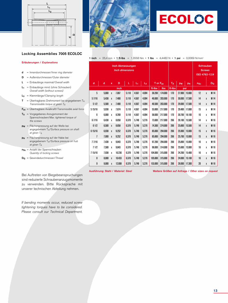
Erläuterungen / Explanations
d = Innendurchmesser/Inner ring diameter
D = Außendurchmesser/Outer diameter
L = Einbaulänge maximal/Overall width
L1 = Einbaulänge mind. (ohne Schrauben) Overall width (without screws)
L3 = Klemmlänge/Clamping length
T = Übertragbares Drehmoment bei angegebenem TA Transmissible torque at given TA
Fax = Übertragbare Axialkraft/Transmissible axial force
TA = Vorgegebenes Anzugsmoment der Spannschrauben/Max. tightened torque of the screws
pW = Flächenpressung auf der Welle bei angegebenem TA/Surface pressure on shaft at given TA
pN = Flächenpressung auf der Nabe bei angegebenem TA/Surface pressure on hub at given TA
nSc = Anzahl der Spannschrauben Quantity of locking screws
DG = Gewindedurchmesser/Thread
Bei Auftreten von Biegebeanspruchungen sind reduzierte Schraubenanzugsmomente zu verwenden. Bitte Rücksprache mit unserer technischen Abteilung nehmen.
If bending moments occur, reduced screw tightening torques have to be considered. Please consult our Technical Department.
Locking Assemblies 7005 ECOLOC1 inch = 25,4 mm • 1 ft-lbs = 1,3558 Nm • 1 lbs = 4,4482 N • 1 psi = 0,0069 N/mm2
Ausführung: Stahl / Material: Steel Weitere Größen auf Anfrage / Other sizes on request
Inch Abmessungen Schrauben
Inch dimensions Screws
ISO 4762-12.9
d d x D L L1 L3 T or Fax TA pW pN nSc DG
inch ft-lbs lbs ft-lbs psi
5 5,000 x 7.087 5.118 4.567 4.094 36.200 174.000 170 27.900 15.900 12 x M 14
5 7/16 5,438 x 7.480 5.118 4.567 4.094 46.000 203.000 170 30.000 17.500 14 x M 14
5 1/2 5,500 x 7.480 5.118 4.567 4.094 46.500 203.000 170 29.600 17.500 14 x M 14
5 15/16 5,938 x 7.874 5.118 4.567 4.094 53.800 217.000 170 29.400 17.800 15 x M 14
6 6,000 x 8.268 5.118 4.567 4.094 58.600 217.000 170 30.700 18.100 16 x M 14
6 7/16 6,438 x 8.858 6.378 5.748 5.276 73.600 217.000 266 26.100 15.500 14 x M 16
6 1/2 6,500 x 8.858 6.378 5.748 5.276 74.300 274.000 266 25.800 15.500 14 x M 16
6 15/16 6,938 x 9.252 6.378 5.748 5.276 85.000 294.000 266 25.900 15.900 15 x M 16
7 7,000 x 9.252 6.378 5.748 5.276 85.800 294.000 266 25.700 15.900 15 x M 16
7 7/16 7,438 x 9.843 6.378 5.748 5.276 97.200 294.000 266 25.800 15.900 16 x M 16
7 1/2 7,500 x 9.843 6.378 5.748 5.276 98.000 314.000 266 25.600 15.900 16 x M 16
7 15/16 7,938 x 10.236 6.378 5.748 5.276 104.000 315.000 266 24.200 15.400 16 x M 16
8 8,000 x 10.433 6.378 5.748 5.276 105.000 315.000 266 24.000 15.100 16 x M 16
9 9,000 x 12.008 6.378 5.748 5.276 153.000 315.000 266 28.000 17.300 20 x M 16
13

7006 ECOLOCSpannsätze · Locking Assemblies
Hat alle positiven Eigenschaften wie die Baureihe 7003 ECOLOC. Jedoch wird durch den größeren Flanschdurch messer die Axialverschie bung der Nabe bei der Montage verhindert. Wird auch bei Bandtrommeln verwendet.
7006 ECOLOC
Has all positive features of series 7003 ECOLOC. However, through the bigger flange diameter an axial displacement of the hub during mounting is averted. Is also applied with belt pulleys.
7006 ECOLOC
Technische HinweiseTechnical information
Oberflächen / Surface finishes Für Welle und Nabenbohrung For shafts and hub bores Ra = 1,6 µm
Toleranzen / Tolerances Wir empfehlen folgende Einbau- toleranzen We recommend the following mounting tolerances Welle / Shaft: h8 · Nabe / Hub: H8
Typ / Type d x D
7006 ECOLOC 55 x 85
Bestellbeispiel · Ordering example:
Weitere Größen auf Anfrage / Other sizes on requestAusführung: Stahl / Material: Steel
Metrische Abmessungen Schrauben
Metric dimensions Screws
ISO 4762-12.9
d x D D1 L L1 L3 L4 T or Fax TA pW pN nSc DG
mm Nm kN Nm N/mm2
19 x 47 56 34 28 17 23 270 28 17 215 95 5 x M 6
20 x 47 56 34 28 17 23 280 28 17 215 95 5 x M 6
22 x 47 56 34 28 17 23 310 28 17 195 95 5 x M 6
24 x 50 59 34 28 17 23 400 32 17 215 105 6 x M 6
25 x 50 59 34 28 17 23 440 34 17 210 105 6 x M 6
28 x 55 64 34 28 17 23 490 34 17 195 100 6 x M 6
30 x 55 64 34 28 17 23 530 34 17 185 100 6 x M 6
32 x 60 69 34 28 17 23 750 46 17 210 110 8 x M 6
35 x 60 69 34 28 17 23 820 46 17 185 110 8 x M 6
38 x 65 74 34 28 17 23 890 46 17 190 110 8 x M 6
40 x 65 74 34 28 17 23 940 46 17 185 110 8 x M 6
42 x 75 84 41 33 20 27 1.600 70 41 240 130 7 x M 8
45 x 75 84 41 33 20 27 1.720 70 41 225 130 7 x M 8
50 x 80 89 41 33 20 27 1.890 74 41 205 125 7 x M 8
55 x 85 94 41 33 20 27 2.400 76 41 210 130 8 x M 8
60 x 90 99 41 33 20 27 2.650 76 41 185 120 8 x M 8
65 x 95 104 41 33 20 27 3.190 80 41 195 130 9 x M 8
70 x 110 119 50 40 24 32 4.910 130 83 215 135 8 x M 10
75 x 115 124 50 40 24 32 5.150 130 83 195 125 8 x M 10
80 x 120 129 50 40 24 32 5.490 130 83 185 120 8 x M 10
85 x 125 134 50 40 24 32 6.620 140 83 195 130 9 x M 10
90 x 130 139 50 40 24 32 6.960 140 83 185 125 9 x M 10
95 x 135 144 50 40 24 32 8.190 160 83 195 135 10 x M 10
100 x 145 154 56 44 26 34 10.100 170 145 205 145 8 x M 12
110 x 155 164 56 44 26 34 11.000 170 145 190 135 8 x M 12
120 x 165 174 56 44 26 34 13.600 200 145 205 140 9 x M 12
130 x 180 189 64 52 34 42 19.000 250 145 185 135 12 x M 12
140 x 190 199 68 54 34 42 21.800 270 230 175 125 9 x M 14
150 x 200 209 68 54 34 42 25.600 320 230 185 135 10 x M 14
160 x 210 219 68 54 34 42 26.100 320 230 175 135 11 x M 14
170 x 225 234 78 64 44 52 30.300 340 230 140 105 12 x M 14
180 x 235 244 78 64 44 52 32.000 340 230 135 105 12 x M 14
190 x 250 259 78 64 44 52 50.000 525 230 157 119 15 x M 14
200 x 260 269 78 64 44 52 52.800 528 230 149 115 15 x M 14
220 x 285 294 88 72 50 57 64.500 585 355 129 100 12 x M 16
240 x 305 314 88 72 50 57 88.000 730 355 148 116 15 x M 16
260 x 325 334 88 72 50 57 114.000 880 355 145 116 18 x M 16
280 x 355 364 102 84 60 66 123.100 880 480 141 111 16 x M 18
300 x 375 384 102 84 60 66 148.250 985 480 146 117 18 x M 18
320 x 405 414 121 101 74 81 182.500 1.140 690 125 110 18 x M 20
340 x 425 434 121 101 74 81 218.000 1.280 690 135 110 21 x M 20
360 x 455 464 137 115 86 93 290.000 1.600 930 135 110 18 x M 22
380 x 475 484 137 115 86 93 305.000 1.600 930 130 105 21 x M 22
400 x 495 504 137 115 86 93 355.000 1.775 930 135 110 21 x M 22
14

Erläuterungen / Explanations
d = Innendurchmesser/Inner ring diameter
D = Außendurchmesser/Outer diameter
D1 = Außendurchmesser Bund/Collar outer diameter
L = Einbaulänge maximal/Overall width
L1 = Einbaulänge mind. (ohne Schrauben) Overall width (without screws)
L3 = Klemmlänge/Clamping length
L4 = Einbaulänge bis Bund Installation length up to colar
T = Übertragbares Drehmoment bei angegebenem TA Transmissible torque at given TA
Fax = Übertragbare Axialkraft/Transmissible axial force
TA = Vorgegebenes Anzugsmoment der Spannschrauben/Max. tightened torque of the screws
pW = Flächenpressung auf der Welle bei angegebenem TA/Surface pressure on shaft at given TA
pN = Flächenpressung auf der Nabe bei angegebenem TA/Surface pressure on hub at given TA
nSc = Anzahl der Spannschrauben Quantity of locking screws
DG = Gewindedurchmesser/Thread
1 inch = 25,4 mm • 1 ft-lbs = 1,3558 Nm • 1 lbs = 4,4482 N • 1 psi = 0,0069 N/mm2
LL1L4L3
D1
d
D
Locking Assemblies 7006 ECOLOC
Ausführung: Stahl / Material: Steel Weitere Größen auf Anfrage / Other sizes on request
Inch Abmessungen Schrauben
Inch dimensions Screws
ISO 4762-12.9
d d x D D1 L L1 L3 L4 T or Fax TA pW pN nSc DG
inch ft-lbs lbs ft-lbs psi
3/4 0,750 x 1.850 2.205 1.339 1.102 0.669 0.906 200 6.290 13 31.160 13.500 5 x M 6
7/8 0,875 x 1.850 2.205 1.339 1.102 0.669 0.906 230 6.290 13 28.400 13.500 5 x M 6
1 1,000 x 1.969 2.323 1.339 1.102 0.669 0.906 325 7.640 13 30.400 15.500 6 x M 6
1 1/8 1,125 x 2.165 2.520 1.339 1.102 0.669 0.906 360 7.640 13 28.400 14.200 6 x M 6
1 3/16 1,188 x 2.165 2.520 1.339 1.102 0.669 0.906 390 7.640 13 27.000 14.200 6 x M 6
1 1/4 1,250 x 2.362 2.717 1.339 1.102 0.669 0.906 555 10.300 13 30.400 16.200 8 x M 6
1 3/8 1,375 x 2.362 2.717 1.339 1.102 0.669 0.906 605 10.300 13 27.000 16.200 8 x M 6
1 7/16 1,438 x 2.559 2.913 1.339 1.102 0.669 0.906 625 10.300 13 28.700 15.900 8 x M 6
1 1/2 1,500 x 2.559 2.913 1.339 1.102 0.669 0.906 655 10.300 13 27.700 15.900 8 x M 6
1 5/8 1,625 x 2.953 3.307 1.614 1.299 0.787 1.063 1.180 15.700 30 34.900 19.100 7 x M 8
1 3/4 1,750 x 2.953 3.307 1.614 1.299 0.787 1.063 1.270 15.700 30 32.600 19.100 7 x M 8
1 7/8 1,875 x 2.953 3.504 1.614 1.299 0.787 1.063 1.330 15.700 30 31.200 18.400 7 x M 8
1 15/16 1,938 x 3.150 3.504 1.614 1.299 0.787 1.063 1.390 16.600 30 29.700 18.400 7 x M 8
2 2,000 x 3.150 3.504 1.614 1.299 0.787 1.063 1.390 16.600 30 29.200 18.400 7 x M 8
2 1/8 2,125 x 3.346 3.701 1.614 1.299 0.787 1.063 1.730 17.100 30 31.000 19.100 8 x M 8
2 3/16 2,188 x 3.346 3.701 1.614 1.299 0.787 1.063 1.770 17.100 30 30.400 19.100 8 x M 8
2 1/4 2,250 x 3.543 3.898 1.614 1.299 0.787 1.063 1.860 17.100 30 28.300 17.700 8 x M 8
2 3/8 2,375 x 3.543 3.898 1.614 1.299 0.787 1.063 1.950 17.100 30 27.000 17.700 8 x M 8
2 7/16 2,438 x 3.740 4.094 1.614 1.299 0.787 1.063 2.230 18.000 30 29.800 19.100 9 x M 8
2 1/2 2,500 x 3.740 4.094 1.614 1.299 0.787 1.063 2.290 18.000 30 29.100 19.100 9 x M 8
2 9/16 2,563 x 3.740 4.094 1.614 1.299 0.787 1.063 2.350 18.000 30 28.400 19.100 9 x M 8
2 11/16 2,688 x 4.331 4.685 1.969 1.575 0.945 1.260 3.530 29.200 61 32.000 19.900 8 x M 10
2 3/4 2,750 x 4.331 4.685 1.969 1.575 0.945 1.260 3.620 29.200 61 31.200 19.900 8 x M 10
2 7/8 2,875 x 4.528 4.882 1.969 1.575 0.945 1.260 3.690 29.200 61 29.000 18.400 8 x M 10
2 15/16 2,938 x 4.528 4.882 1.969 1.575 0.945 1.260 3.800 29.200 61 28.300 18.400 8 x M 10
3 3,000 x 4.724 5.079 1.969 1.575 0.945 1.260 4.050 29.200 61 26.800 17.700 8 x M 10
3 1/4 3,250 x 4.921 5.276 1.969 1.575 0.945 1.260 4.730 31.500 61 29.100 19.100 9 x M 10
3 3/8 3,375 x 4.921 5.276 1.969 1.575 0.945 1.260 4.880 31.500 61 28.300 19.100 9 x M 10
3 7/16 3,438 x 4.921 5.472 1.969 1.575 0.945 1.260 4.980 31.500 61 27.600 18.400 9 x M 10
3 1/2 3,500 x 5.118 5.472 1.969 1.575 0.945 1.260 5.130 31.500 61 26.800 18.400 9 x M 10
3 3/4 3,750 x 5.315 5.669 1.969 1.575 0.945 1.260 6.040 36.000 61 28.300 19.900 10 x M 10
3 15/16 3,938 x 5.709 6.063 2.205 1.732 1.024 1.339 7.450 38.200 107 29.700 21.000 8 x M 12
4 4,000 x 5.709 6.063 2.205 1.732 1.024 1.339 7.560 38.200 107 29.200 21.000 8 x M 12
4 7/16 4,438 x 6.102 6.457 2.205 1.732 1.024 1.339 8.110 38.200 107 27.500 19.600 8 x M 12
4 3/4 4,750 x 6.496 6.850 2.205 1.732 1.024 1.339 10.000 45.000 107 29.700 20.600 9 x M 12
4 15/16 4,938 x 7.087 7.441 2.520 2.047 1.339 1.654 13.400 56.200 107 27.900 19.900 12 x M 12
5 5,000 x 7.087 7.441 2.520 2.047 1.339 1.654 14.000 56.200 107 27.000 19.900 12 x M 12
5 7/16 5,438 x 7.480 7.835 2.677 2.126 1.339 1.654 16.100 60.700 170 25.700 18.400 9 x M 14
5 15/16 5,938 x 7.874 8.228 2.677 2.126 1.339 1.654 18.900 71.900 170 26.800 19.900 10 x M 14
6 7/16 6,438 x 8.858 9.213 3.071 2.520 1.732 2.047 22.300 76.400 170 20.300 15.200 12 x M 14
6 15/16 6,938 x 9.252 9.606 3.071 2.520 1.732 2.047 23.600 76.400 170 19.600 15.200 12 x M 14
15

7007 ECOLOCSpannsätze · Locking Assemblies
Ist eine Abwandlung des 7004 ECOLOC mit dessen sämtlichen positiven Eigen-schaften, jedoch wird hier wie bei 7006 ECOLOC die Axialverschie bung bei der Montage verhindert.
7007 ECOLOC
Is a modification of 7004 ECOLOC with all its positive features, but here - same as 7006 ECOLOC - the axial displacement during mounting is averted.
7007 ECOLOC
Technische HinweiseTechnical information
Oberflächen / Surface finishes Für Welle und Nabenbohrung For shafts and hub bores Ra = 1,6 µm
Toleranzen / Tolerances Wir empfehlen folgende Einbautoleranzen We recommend the following mounting tolerances Welle / Shaft: h8 · Nabe / Hub: H8
Typ / Type d x D
7007 ECOLOC 110 x 155
Bestellbeispiel · Ordering example:
Weitere Größen auf Anfrage / Other sizes on requestAusführung: Stahl / Material: Steel
Metrische Abmessungen Schrauben
Metric dimensions Screws
ISO 4762-12.9
d x D D1 L L1 L3 L4 T or Fax TA pW pN nSc DG
mm Nm kN Nm N/mm2
19 x 47 53 45 39 26 31 320 33 17 180 70 6 x M 620 x 47 53 45 39 26 31 330 33 17 170 70 6 x M 622 x 47 53 45 39 26 31 370 33 17 155 70 6 x M 624 x 50 56 45 39 26 31 400 33 17 140 70 6 x M 625 x 50 56 45 39 26 31 420 33 17 135 70 6 x M 628 x 55 61 45 39 26 31 470 33 17 120 60 6 x M 630 x 55 61 45 39 26 31 500 33 17 115 60 6 x M 632 x 60 66 45 39 26 31 710 44 17 140 75 8 x M 635 x 60 66 45 39 26 31 780 44 17 130 75 8 x M 638 x 65 71 45 39 26 31 850 44 17 120 70 8 x M 640 x 65 71 45 39 26 31 890 44 17 110 70 8 x M 642 x 75 81 55 47 30 36 1.270 61 41 130 70 6 x M 845 x 75 81 55 47 30 36 1.360 61 41 120 70 6 x M 848 x 80 86 55 47 30 36 1.940 81 41 150 90 8 x M 850 x 80 86 55 47 30 36 2.020 81 41 145 90 8 x M 855 x 85 91 55 47 30 36 2.220 81 41 130 85 8 x M 860 x 90 96 55 47 30 36 2.430 81 41 120 80 8 x M 865 x 95 101 55 47 30 36 2.630 81 41 110 75 8 x M 870 x 110 116 72 62 40 46 4.580 131 83 125 80 8 x M 1075 x 115 121 72 62 40 46 4.900 131 83 115 75 8 x M 1080 x 120 126 72 62 40 46 5.230 131 83 110 70 8 x M 1085 x 125 131 72 62 40 46 6.950 163 83 125 85 10 x M 1090 x 130 136 72 62 40 46 7.350 163 83 120 85 10 x M 1095 x 135 141 72 62 40 46 7.760 163 83 115 80 10 x M 10
100 x 145 151 89 77 46 52 9.780 196 83 115 80 8 x M 12110 x 155 161 89 77 46 52 10.750 196 145 100 75 8 x M 12120 x 165 171 89 77 46 52 14.660 244 145 115 85 10 x M 12130 x 180 186 89 77 46 52 19.060 293 145 130 95 12 x M 12140 x 190 196 98 84 51 59 23.600 337 230 125 90 10 x M 14150 x 200 206 98 84 51 59 30.340 405 230 140 105 12 x M 14160 x 210 216 98 84 51 59 32.360 405 230 130 100 12 x M 14170 x 225 231 98 84 51 59 40.120 472 230 145 110 14 x M 14180 x 235 241 98 84 51 59 42.480 472 230 135 105 14 x M 14190 x 250 259 98 84 51 59 46.400 488 230 136 104 15 x M 14200 x 260 259 98 84 51 59 48.800 488 230 130 100 15 x M 14
16

Erläuterungen / Explanations
d = Innendurchmesser/Inner ring diameter
D = Außendurchmesser/Outer diameter
D1 = Außendurchmesser Bund/Collar outer diameter
L = Einbaulänge maximal/Overall width
L1 = Einbaulänge mind. (ohne Schrauben) Overall width (without screws)
L3 = Klemmlänge/Clamping length
L4 = Einbaulänge bis Bund Installation length up to colar
T = Übertragbares Drehmoment bei angegebenem TA Transmissible torque at given TA
Fax = Übertragbare Axialkraft/Transmissible axial force
TA = Vorgegebenes Anzugsmoment der Spannschrauben/Max. tightened torque of the screws
pW = Flächenpressung auf der Welle bei angegebenem TA/Surface pressure on shaft at given TA
pN = Flächenpressung auf der Nabe bei angegebenem TA/Surface pressure on hub at given TA
nSc = Anzahl der Spannschrauben Quantity of locking screws
DG = Gewindedurchmesser/Thread
LL1
L4L3
d
D D1
Locking Assemblies 7007 ECOLOC1 inch = 25,4 mm • 1 ft-lbs = 1,3558 Nm • 1 lbs = 4,4482 N • 1 psi = 0,0069 N/mm2
Ausführung: Stahl / Material: Steel Weitere Größen auf Anfrage / Other sizes on request
Inch Abmessungen Schrauben
Inch dimensions Screws
ISO 4762-12.9
d d x D D1 L L1 L4 T or Fax TA pW pN nSc DG
inch ft-lbs lbs ft-lbs psi
3/4 0,750 x 1.850 2.087 1.772 1.535 1.220 235 7.400 13 26.000 10.400 6 x M 6
7/8 0,875 x 1.850 2.087 1.772 1.535 1.220 270 7.400 13 22.500 10.400 6 x M 6
1 1,000 x 1.969 2.205 1.772 1.535 1.220 310 7.400 13 19.700 9.900 6 x M 6
1 1/8 1,125 x 2.165 2.402 1.772 1.535 1.220 345 7.400 13 17.500 9.000 6 x M 6
1 3/16 1,188 x 2.165 2.402 1.772 1.535 1.220 370 7.400 13 16.400 9.000 6 x M 6
1 1/4 1,250 x 2.362 2.598 1.772 1.535 1.220 525 9.890 13 20.600 11.000 8 x M 6
1 3/8 1,375 x 2.362 2.598 1.772 1.535 1.220 575 9.890 13 18.800 11.000 8 x M 6
1 7/16 1,438 x 2.559 2.795 1.772 1.535 1.220 595 9.890 13 18.100 10.600 8 x M 6
1 1/2 1,500 x 2.559 2.795 1.772 1.535 1.220 625 9.890 13 17.300 10.100 8 x M 6
1 5/8 1,625 x 2.953 3.189 2.165 1.850 1.417 940 13.700 30 18.600 10.300 6 x M 8
1 3/4 1,750 x 2.953 3.189 2.165 1.850 1.417 1.010 13.700 30 17.300 10.300 6 x M 8
1 7/8 1,875 x 2.953 3.386 2.165 1.850 1.417 1.270 18.200 30 20.000 11.900 6 x M 8
1 15/16 1,938 x 3.150 3.386 2.165 1.850 1.417 1.490 18.200 30 20.700 12.900 8 x M 8
2 2,000 x 3.150 3.583 2.165 1.850 1.417 1.550 18.200 30 20.000 12.600 8 x M 8
2 1/8 2,125 x 3.346 3.583 2.165 1.850 1.417 1.550 18.200 30 19.900 12.600 8 x M 8
2 3/16 2,188 x 3.346 3.583 2.165 1.850 1.417 1.640 18.200 30 18.800 12.200 8 x M 8
2 1/4 2,250 x 3.543 3.780 2.165 1.850 1.417 1.710 18.200 30 18.100 11.900 8 x M 8
2 3/8 2,375 x 3.543 3.780 2.165 1.850 1.417 1.790 18.200 30 17.300 11.500 8 x M 8
2 7/16 2,438 x 3.740 3.976 2.165 1.850 1.417 1.790 18.200 30 16.700 11.200 8 x M 8
2 1/2 2,500 x 3.740 3.976 2.165 1.850 1.417 1.860 18.200 30 16.700 11.200 8 x M 8
2 9/16 2,563 x 3.740 3.976 2.165 1.850 1.417 1.940 18.200 30 15.900 10.900 8 x M 8
2 11/16 2,688 x 4.331 4.567 2.835 2.441 1.811 2.710 29.400 61 17.100 11.200 8 x M 10
2 3/4 2,750 x 4.331 4.567 2.835 2.441 1.811 3.370 29.400 61 18.000 11.500 8 x M 10
2 7/8 2,875 x 4.528 4.764 2.835 2.441 1.811 3.510 29.400 61 17.300 11.900 8 x M 10
2 15/16 2,938 x 4.528 4.764 2.835 2.441 1.811 3.620 29.400 61 16.800 10.900 8 x M 10
3 3,000 x 4.724 4.961 2.835 2.441 1.811 3.860 29.400 61 15.700 10.400 8 x M 10
3 1/4 3,250 x 4.921 5.157 2.835 2.441 1.811 4.680 36.600 61 15.500 10.900 10 x M 10
3 3/8 3,375 x 4.921 5.157 2.835 2.441 1.811 5.120 36.600 61 18.400 12.600 10 x M 10
3 7/16 3,438 x 4.921 5.354 2.835 2.441 1.811 5.330 36.600 61 17.700 12.200 10 x M 10
3 1/2 3,500 x 5.118 5.354 2.835 2.441 1.811 5.420 36.600 61 17.400 12.000 10 x M 10
3 3/4 3,750 x 5.315 5.551 2.835 2.441 1.811 5.720 36.600 61 16.500 11.600 10 x M 10
3 15/16 3,938 x 5.709 5.945 3.504 3.031 2.047 7.210 44.100 61 16.400 11.300 8 x M 12
4 4,000 x 5.709 5.945 3.504 3.031 2.047 7.500 44.100 61 17.100 11.700 8 x M 12
4 7/16 4,438 x 6.102 6.339 3.504 3.031 2.047 7.930 44.100 107 14.800 10.600 8 x M 12
4 3/4 4,750 x 6.496 6.732 3.504 3.031 2.047 10.800 54.900 107 17.000 12.300 10 x M 12
4 15/16 4,938 x 7.087 7.323 3.504 3.031 2.047 12.400 65.900 107 17.700 12.800 12 x M 12
5 5,000 x 7.087 7.323 3.504 3.031 2.047 14.100 65.900 107 18.800 13.600 12 x M 12
5 7/16 5,438 x 7.480 7.717 3.858 3.307 2.323 17.400 75.800 170 18.100 13.300 10 x M 14
5 15/16 5,938 x 7.874 8.110 3.858 3.307 2.323 22.400 91.000 170 20.300 15.200 12 x M 14
6 7/16 6,438 x 8.858 9.094 3.858 3.307 2.323 29.600 106.000 170 20.900 15.800 14 x M 14
6 15/16 6,938 x 9.252 9.488 3.858 3.307 2.323 31.300 106.000 170 19.700 15.100 14 x M 14
17

7110 ECOLOCSpannsätze · Locking Assemblies
Besonders klein bauender selbstzentrie-render Spannsatz ohne Axialver schiebung. Da die Spannschrauben außer halb der eigentlichen Spannstelle liegen und die Pressungen relativ gering sind kann die Nabe ökonomisch klein gestaltet werden.
7110 ECOLOC
Specially small dimensioned self-centering Locking Assembly without axial displace-ment. As the locking screws are located out of the actual clamping area and the pressures are relatively low, the hub can be designed economically small.
7110 ECOLOC
Technische HinweiseTechnical information
Oberflächen / Surface finishes Für Welle und Nabenbohrung For shafts and hub bores Ra = 1,6 µm
Toleranzen / Tolerances Wir empfehlen folgende Einbau- toleranzen We recommend the following mounting tolerances Welle / Shaft: h8 · Nabe / Hub: H8
Typ / Type d x D
7110 ECOLOC 70 x 90
Bestellbeispiel · Ordering example:
Weitere Größen auf Anfrage / Other sizes on requestAusführung: Stahl / Material: Steel
Metrische Abmessungen Schrauben
Metric dimensions Screws
ISO 4762-12.9
d x D D1 L L1 L4 L8 d1 T or Fax TA pW pN nSc DG
mm Nm kN Nm N/mm2
8 x 15 27 30 26 12 22 20 30 7 4 230 120 4 x M 4
9 x 16 28 31 27 14 23 21 34 7 4 170 100 4 x M 4
10 x 16 28 31 27 14 23 21 37 7 4 160 100 4 x M 4
11 x 18 32 31 27 14 23 23 51 10 5 180 110 4 x M 4
12 x 18 32 31 27 14 23 23 56 10 5 155 110 4 x M 4
13 x 23 38 31 27 14 23 28 61 10 5 150 85 4 x M 4
14 x 23 38 31 27 14 23 28 65 10 5 140 85 4 x M 4
15 x 24 44 42 36 16 29 31 110 17 17 180 115 3 x M 6
16 x 24 44 42 36 16 29 31 120 17 17 170 115 3 x M 6
17 x 26 47 44 38 18 31 33 165 22 17 190 135 4 x M 6
18 x 26 47 44 38 18 31 33 180 22 17 180 135 4 x M 6
19 x 27 48 44 38 18 31 34 190 22 17 170 125 4 x M 6
20 x 28 49 44 38 18 31 35 200 22 17 150 115 4 x M 6
22 x 32 53 51 45 25 38 39,5 230 21 17 115 80 4 x M 6
24 x 34 55 51 45 25 38 41,5 255 21 17 105 75 4 x M 6
25 x 34 55 51 45 25 38 41,5 255 21 17 100 75 4 x M 6
28 x 39 60 51 45 25 38 46 370 31 17 110 80 5 x M 6
30 x 41 62 51 45 25 38 48 475 31 17 125 90 6 x M 6
32 x 43 64 56 50 30 43 50,5 505 31 17 95 75 6 x M 6
35 x 47 68 56 50 30 43 54 740 42 17 120 90 8 x M 6
38 x 50 71 56 50 30 43 57 800 42 17 110 85 8 x M 6
40 x 53 74 58 52 32 45 60 950 53 17 110 85 9 x M 6
42 x 55 77 58 52 32 45 62 995 78 17 105 80 4 x M 6
45 x 59 85 72 64 40 56 68,5 1.750 78 41 130 100 8 x M 8
48 x 62 87 72 64 40 56 71,5 1.870 78 41 120 95 8 x M 8
50 x 65 91 82 74 50 66 74,5 2.430 97 41 115 90 10 x M 8
55 x 71 98 82 74 50 66 80 2.670 97 41 105 80 10 x M 8
60 x 77 103 82 74 50 66 86 2.920 97 41 95 75 10 x M 8
65 x 84 110 82 74 50 66 93 3.160 97 41 90 70 10 x M 8
70 x 90 119 101 91 60 80 101 4.330 123 83 85 70 8 x M 10
75 x 95 126 101 91 60 80 106 5.310 142 83 90 75 9 x M 10
80 x 100 131 106 96 65 85 111 7.580 190 83 110 85 12 x M 10
85 x 106 137 106 96 65 85 117 7.990 190 83 100 80 12 x M 10
90 x 112 143 106 96 65 85 123 9.960 222 83 110 90 14 x M 10
95 x 120 153 106 96 65 85 131 10.500 222 83 105 85 14 x M 10
100 x 125 162 114 102 65 89 138 13.600 273 145 125 100 12 x M 12
110 x 140 177 119 107 70 94 153 15.000 273 145 105 80 12 x M 12
120 x 155 195 139 127 90 114 168 21.800 364 145 100 75 16 x M 12
130 x 165 205 139 127 90 114 178 23.700 364 145 90 70 16 x M 12
18

Weitere Größen auf Anfrage / Other sizes on requestAusführung: Stahl / Material: Steel
Erläuterungen / Explanations
d = Innendurchmesser/Inner ring diameter
d1 = Lochkreis-Durchmesser/Pitch circle diameter
D = Außendurchmesser/Outer diameter
D1 = Außendurchmesser Bund/Collar outer diameter
L = Einbaulänge maximal/Overall width
L1 = Einbaulänge mind. (ohne Schrauben) Overall width (without screws)
L4 = Einbaulänge bis Bund Installation length up to collar
L8 = Länge L4 + Länge Distanzbuchse L8 Length L4 + length spacer bushing L8
T = Übertragbares Drehmoment bei angegebenem TA Transmissible torque at given TA
Fax = Übertragbare Axialkraft/Transmissible axial force
TA = Vorgegebenes Anzugsmoment der Spannschrauben/Max. tightened torque of the screws
pW = Flächenpressung auf der Welle bei angegebenem TA/Surface pressure on shaft at given TA
pN = Flächenpressung auf der Nabe bei angegebenem TA/Surface pressure on hub at given TA
nSc = Anzahl der Spannschrauben Quantity of locking screws
DG = Gewindedurchmesser/Thread
Locking Assemblies 7110 ECOLOC
LL1
L4
D1
d 1
Dd
Inch Abmessungen Schrauben
Inch dimensions Screws
ISO 4762-12.9
d d x D D1 L L1 L4 L8 d1 T or Fax TA pW pN nSc DG
mm inch ft-lbs lbs ft-lbs psi
8 0.315 x 0.591 1.063 1.181 1.024 0.472 0.866 0.787 22 1.562 3 33.333 17.391 4 x M 4
9 0.354 x 0.630 1.102 1.220 1.063 0.551 0.906 0.827 25 1.562 3 24.638 14.493 4 x M 4
10 0.394 x 0.630 1.102 1.220 1.063 0.551 0.906 0.827 27 1.562 3 23.188 14.493 4 x M 4
11 0.433 x 0.709 1.260 1.220 1.063 0.551 0.906 0.906 38 2.231 3.7 26.087 15.942 4 x M 4
12 0.472 x 0.709 1.260 1.220 1.063 0.551 0.906 0.906 41 2.231 3.7 22.464 15.942 4 x M 4
13 0.512 x 0.906 1.496 1.220 1.063 0.551 0.906 1.102 45 2.231 3.7 21.739 12.319 4 x M 4
14 0.551 x 0.906 1.496 1.220 1.063 0.551 0.906 1.102 48 2.231 3.7 20.290 12.319 4 x M 4
15 0.591 x 0.945 1.732 1.654 1.417 0.630 1.142 1.220 81 3.793 13 26.087 16.667 3 x M 6
16 0.630 x 0.945 1.732 1.654 1.417 0.630 1.142 1.220 89 3.793 13 24.638 16.667 3 x M 6
17 0.669 x 1.024 1.850 1.732 1.496 0.709 1.220 1.299 122 4.909 13 27.536 19.565 4 x M 6
18 0.709 x 1.024 1.850 1.732 1.496 0.709 1.220 1.299 133 4.909 13 26.087 19.565 4 x M 6
19 0.748 x 1.063 1.890 1.732 1.496 0.709 1.220 1.339 140 4.909 13 24.638 18.116 4 x M 6
20 0.787 x 1.102 1.929 1.732 1.496 0.709 1.220 1.378 148 4.909 13 21.739 16.667 4 x M 6
22 0.866 x 1.260 2.087 2.008 1.772 0.984 1.496 1.555 170 4.685 13 16.667 11.594 4 x M 6
24 0.945 x 1.339 2.165 2.008 1.772 0.984 1.496 1.634 188 4.685 13 15.217 10.870 4 x M 6
25 0.984 x 1.339 2.165 2.008 1.772 0.984 1.496 1.634 188 4.685 13 14.493 10.870 4 x M 6
28 1.102 x 1.535 2.362 2.008 1.772 0.984 1.496 1.811 273 6.917 13 15.942 11.594 5 x M 6
30 1.181 x 1.614 2.441 2.008 1.772 0.984 1.496 1.890 350 6.917 13 18.116 13.043 6 x M 6
32 1.260 x 1.693 2.520 2.205 1.969 1.181 1.693 1.988 372 6.917 13 13.768 10.870 6 x M 6
35 1.378 x 1.850 2.677 2.205 1.969 1.181 1.693 2.126 546 9.371 13 17.391 13.043 8 x M 6
38 1.496 x 1.969 2.795 2.205 1.969 1.181 1.693 2.244 590 9.371 13 15.942 12.319 8 x M 6
40 1.575 x 2.087 2.913 2.283 2.047 1.260 1.772 2.362 701 11.825 13 15.942 12.319 9 x M 6
42 1.654 x 2.165 3.031 2.283 2.047 1.260 1.772 2.441 734 17.403 13 15.217 11.594 4 x M 6
45 1.772 x 2.323 3.346 2.835 2.520 1.575 2.205 2.697 1.291 17.403 30 18.841 14.493 8 x M 8
48 1.890 x 2.441 3.425 2.835 2.520 1.575 2.205 2.815 1.379 17.403 30 17.391 13.768 8 x M 8
50 1.969 x 2.559 3.583 3.228 2.913 1.969 2.598 2.933 1.792 21.642 30 16.667 13.043 10 x M 8
55 2.165 x 2.795 3.858 3.228 2.913 1.969 2.598 3.150 1.969 21.642 30 15.217 11.594 10 x M 8
60 2.362 x 3.031 4.055 3.228 2.913 1.969 2.598 3.386 2.154 21.642 30 13.768 10.870 10 x M 8
65 2.559 x 3.307 4.331 3.228 2.913 1.969 2.598 3.661 2.331 21.642 30 13.043 10.145 10 x M 8
70 2.756 x 3.543 4.685 3.976 3.583 2.362 3.150 3.976 3.194 27.443 61 12.319 10.145 8 x M 10
75 2.953 x 3.740 4.961 3.976 3.583 2.362 3.150 4.173 3.917 31.682 61 13.043 10.870 9 x M 10
80 3.150 x 3.937 5.157 4.173 3.780 2.559 3.346 4.370 5.591 42.392 61 15.942 12.319 12 x M 10
85 3.346 x 4.173 5.394 4.173 3.780 2.559 3.346 4.606 5.893 42.392 61 14.493 11.594 12 x M 10
90 3.543 x 4.409 5.630 4.173 3.780 2.559 3.346 4.843 7.346 49.531 61 15.942 13.043 14 x M 10
95 3.740 x 4.724 6.024 4.173 3.780 2.559 3.346 5.157 7.745 49.531 61 15.217 12.319 14 x M 10
100 3.937 x 4.921 6.378 4.488 4.016 2.559 3.504 5.433 10.031 60.910 107 18.116 14.493 12 x M 12
110 4.331 x 5.512 6.969 4.685 4.213 2.756 3.701 6.024 11.064 60.910 107 15.217 11.594 12 x M 12
120 4.724 x 6.102 7.677 5.472 5.000 3.543 4.488 6.614 16.079 81.214 107 14.493 10.870 16 x M 12
130 5.118 x 6.496 8.071 5.472 5.000 3.543 4.488 7.008 17.480 81.214 107 13.043 10.145 16 x M 12
1 inch = 25,4 mm • 1 ft-lbs = 1,3558 Nm • 1 lbs = 4,4482 N • 1 psi = 0,0069 N/mm2
19

Notizen · Notes
20

Notizen · Notes
21

22

Faxanfrage · Fax-Inquiry
Für die Auslegung einer ECOLOC Welle-Nabe-VerbindungTo get a design proposal for ECOLOC shaft-hub-connection
RINGFEDER POWER TRANSMISSION GMBH, 64823 Groß-Umstadt
Fax +49 (0) 6078 9385-100 Absender / Addresser
Firma / Company
z. Hd. / attn. Abt. / Dept.
Adresse / Address
Phone Fax
Wir bitten um ein Beratungsgespräch. Rufen Sie uns bitte unter /We ask for a consulting discussion. Please call us under zurück / back
Um unseren Mitarbeitern die Beratung Ihres Problems zu erleichtern und Irrtümern bzw. Fehlern vorzubeugen, sollte Ihre Anfrage die nachfolgenden Angaben enthalten: / To make it easier for our technical staff and to avoid errors or mistakes your enquiry should include the following information:
Angaben für den Beratungs-Service / Information for technical service
Maximal auftretende Belastungen / Expected maximum loads:
Max. Drehmoment / Max. torque T max. = NmMax. Biegemoment / Max. bending moment Mb max. = NmMax. Axiallast / Max. axial load Fax max. = kNMax. Radiallast / Max. radial load Fr max. = kN
Dimensionen, Werkstoffe / Dimensions, materials:
Durchmesser der Welle / Shaft diameter dw = mmBei Hohlwelle, InnendurchmesserIn case of hollow shaft, internal diameter dB = mmDrehzahl der Welle / Speed revolutions n = 1/minAußendurchmesser Nabe / Hub outside diameter DN = mmNabenbreite / Hub width LN = mmNabenmaterial bzw. Streckgrenze / Hub material / yield strength Rp0,2N = N/mm2
Wellenmaterial bzw. Streckgrenze / Shaft material / yield strength Rp0,2W = N/mm2
Betriebstemperatur der Verbindung / Temperature of the connection Temp. = °C
Sonstige Angaben / Additional information
Bitte fügen Sie Ihrer Anfrage eine Zeichnung oder Skizze bei!Please send a drawing or sketch together with your inquiry!
23

www.ecoloc.comRINGFEDER POWER TRANSMISSION
As world leader in the shaft-hub connector market, RINGFEDER POWER TRANSMISSION today offers more than ever before. Excellent technical know-how together with an improved production and sales organization are available to those who appreciate the benefits of application experience, flexibility, innovation and reliability.
Use our Strength!
Als Weltmarktführer im Bereich Welle-Nabe-Verbin dungen bietet RINGFEDER POWER TRANSMISSION heute mehr als je zuvor. Ein exzellentes Know-How und eine verbesserte Produkt- und Vertriebsstruktur, stehen heute all´ jenen zur Verfügung, die Erfahrung, Flexibilität und Innovation zu schätzen wissen.
Nutzen Sie unsere Stärken!
Hotline+49 (0) 6078 9385-0
Fax+ 49 (0) 6078 9385-100
Lieferung / Deliveryinnerhalb von 24 Stundenwithin 24 hours
RINGFEDER POWER TRANSMISSIONQualitätsmanagementQuality ManagementDIN EN ISO 9001:2008
RINGFEDER POWER TRANSMISSION GMBHWerner-Heisenberg-Straße 18, D-64823 Groß-Umstadt, Germany · Phone: +49 (0) 6078 9385-0 · Fax: +49 (0) 6078 9385-100 E-mail: [email protected] · E-mail: [email protected]
RINGFEDER POWER TRANSMISSION USA CORPORATION165 Carver Avenue, Westwood, NJ 07675, USA · Toll Free: +1 888 746-4333 · Phone: +1 201 666 3320Fax: +1 201 664 6053 · E-mail: [email protected] · E-mail: [email protected]
RINGFEDER POWER TRANSMISSION INDIA PRIVATE LIMITEDPlot No. 4, Door No. 220, Mount - Poonamallee Road, Kattupakkam, Chennai – 600 056, IndiaPhone: +91 (0) 44-2679-1411 · Fax: +91 (0) 44-2679-1422 · E-mail: [email protected] · E-mail: [email protected]
KUNSHAN RINGFEDER POWER TRANSMISSION COMPANY LIMITEDGerman Industry Park, No. 10 Dexin Road, Zhangpu 215321, Kunshan, Jiangsu Province, P.R. ChinaPhone: +86 (0) 512-5745-3960 · Fax: +86 (0) 512-5745-3961 · E-mail: [email protected]