Embed Size (px)
Citation preview
IEEE T R A N S A C T I O N S ON I N S T R U M E N T A T I O N A N D M E A S U R E M E N T , VOL. IM-25, NO. 4, D E C E M B E R 1976 465
1974. [8] G. Becker, "Neues über Zeit, Frequenz und Länge," Kleinheubacher
Berichte, vol. 19, pp. 305-323,1976. [9] G. Becker and B. Fischer, "Abbildungseigenschaften von kurzen
magnetischen Ablenksystemen für Atomstrahlen unter Berück-sichtigung der Geschwindigkeitsverteilung, Part I: Auswertung mit numerischer Integration," Z. Angew. Phys., vol. 19, pp. 537-542, 1965; "Part II: Näherungstheorie," Z. Angew. Phys., vol. 20, pp.
71-73,1965. [10] G. Becker and B. Fischer, "Ablenkung von Atomstrahlen in langen
zylindrischen Ablenksystemen unter Berücksichtigung der Ge-schwindigkeitsverteilung," Z. Angew. Phys., vol. 21, pp. 492-499, 1966.
[11] G. Becker, "Frequenzvergleiche mit dem primären Zeit- und Fre-quenznormal CSl der Physikalisch-Technischen Bundesanstalt zwischen 1969 und 1973," PTB-Mitt., vol. 83, pp. 319-326,1973.
Electronic Circuits Showing a Level-Independent Phase Shift for
Hydrogen-Maser Work Applications
R O L A N D B A R I L L E T AND C L A U D E A U D O I N
Abstract—The origin of spurious level-dependent phase shifts occuring in amplifiers is analyzed. The effects of nonlinearities in transistors and of a bandwidth limitation are stated. Rules for the design of electronic circuits in which this effect must be minimized are given. Experimental results related to a 40-dB amplifier and to an amplitude limiter, both at 5.75 kHz, are described. The tuning of a hydrogen-maser cavity with the condition that the phase of oscillation does not depend on the amplitude of oscillation is con-sidered. A preliminary precise test of the method is reported and discussed.
I. INTRODUCTION
TH E W E L L - K N O W N tuning method of the microwave cavity of a hydrogen maser [1] requires a modula t ion
of the atomic beam in tens i ty in order to modu la t e t h e atomic l inewidth [2]-[5]. Th i s flux variat ion induces a modulation of the level of oscillation, and it has been stated in the pas t t h a t such a modula t ion affects t h e shor t t e r m frequency stability of the maser when au to tuning systems are pu t into operat ion. Th i s may be due to spur ious am-pl i tude correlated phase shifts in electronic circuits . Fu r -thermore , the implementa t ion of an a l ternat ive m e t h o d for the cavity tun ing of a hydrogen maser , which is based on the observation of a modula t ion of t he phase of oscil-lation [6] occurring when the level of oscillation is modu-lated, critically depends on t h e use of electronic circuits showing, as far as possible, a level independent phase shift, of the order of 10~ 3 degree for ampl i tude var ia t ions of 3 dB .
Electronic circuits in which the aforementioned spurious effect has been minimized are described and a preliminary precise tes t of t h e phase m e t h o d for t h e t un ing of a hy-drogen-maser cavity is repor ted .
Manuscript received June 29,1976. The authors are with the Laboratoire de l'Horloge Atomique, Equipe
de Recherche du CNRS, Bâtiment 221, Université Paris Sud, 91405— Orsay, France.
I I . CIRCUITS SHOWING MINIMIZED LEVEL
D E P E N D E N T P H A S E SHIFTS
Only resul ts re la ted to circuits with resistive loads will be given here.
A. Effect of Nonlinearities in Bipolar Transistor Parameters
An analysis of the effect of nonlineari t ies in various circuits, which will be repor ted elsewhere, shows t h a t the spur ious level d e p e n d e n t phase shifts are propor t ional to t he square of t he ampl i tude of t h e voltages. T h e y are also proportional to the phase lag in the considered circuit, and therefore are smaller if t h e working frequency is far from bo th t he low-pass and high-pass frequency cutoffs of t he circuit.
T h e analysis of common emitter voltage amplifiers using bipolar t rans is tors shows t h a t t h e effect of the nonl inear-ities of t he inpu t resis tance and the i npu t capaci tance of the transistor are negligible when compared to those of the o u t p u t pa ramete r s . Th i s is re la ted to t he squared ampli-t u d e dependence of t he spurious phase shift and to the effect of emi t t e r feedback on t h e i npu t impedance . T h e equivalent ou tpu t circuit to be considered is given on Fig. 1 where Rg is approximate ly t h e o u t p u t resistance of t h e t rans is tor and Cg t he base to collector capacitor. R is t he load resistance and C a s t ray capacitor. As, in t ransis tors , the output resistance and capacitance are a function of the collector current , and , therefore of vs, we set
Rg = fi0(l + αιϋ8 + M , 2 ) " 1 (1)
and
Cg = C0(l + a2us + b2vs
2). (2)
466 IEEE T R A N S A C T I O N S O N I N S T R U M E N T A T I O N A N D M E A S U R E M E N T , D E C E M B E R 1976
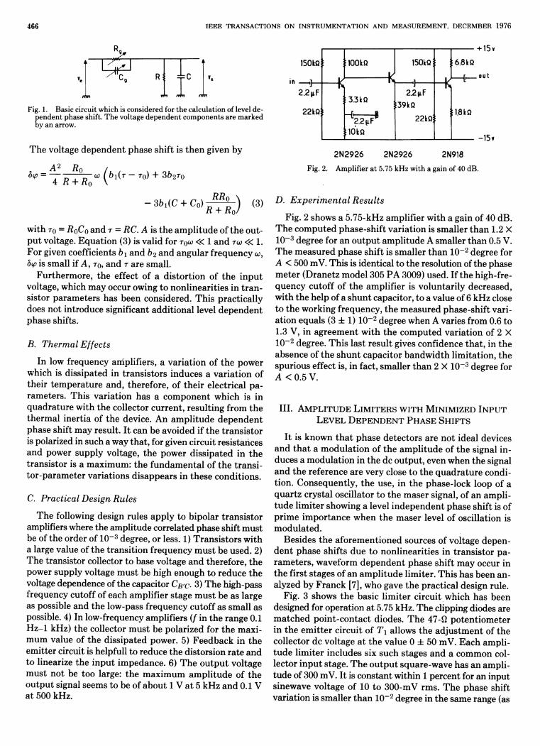
Fig. 1. Basic circuit which is considered for the calculation of level de-pendent phase shift. The voltage dependent components are marked by an arrow.
T h e voltage dependen t phase shift is t h e n given by
αφ = 4~7Γ7ΤΓ ω (bi(r - r 0 ) + Sb2ro 4 R + Ho \
with TO = RoCo and r = RC. A is t h e ampl i tude of t h e out-p u t voltage. Equa t ion (3) is valid for τ 0ω « 1 and τω « 1. For given coefficients bi and b2 and angular frequency ω, δφ is small if A, ro, and τ are small.
Fur the rmore , the effect of a dis tor t ion of t he i npu t voltage, which may occur owing to nonl ineari t ies in t r a n -sistor parameters has been considered. Th i s practical ly does not introduce significant addit ional level dependen t phase shifts.
B. Thermal Effects
In low frequency amplifiers, a var iat ion of t he power which is dissipated in t ransis tors induces a variat ion of their t empera tu re and, therefore, of thei r electrical pa-rameters . Th is variat ion has a componen t which is in quadra tu re with the collector current , resul t ing from the the rmal inertia of t he device. An ampl i tude d e p e n d e n t phase shift may result . I t can be avoided if t he t rans is tor is polarized in such a way tha t , for given circuit resistances and power supply voltage, t he power diss ipated in t h e t ransis tor is a maximum: the fundamenta l of t h e t rans i -to r -parameter variat ions d isappears in these condi t ions.
C. Practical Design Rules
T h e following design rules apply to bipolar t rans is tor amplifiers where the ampli tude correlated phase shift mus t be of t he order of 10~ 3 degree, or less. 1) Trans i s to rs wi th a large value of the t rans i t ion frequency m u s t be used. 2) T h e transistor collector to base voltage and therefore, t h e power supply voltage m u s t be high enough to reduce t h e voltage dependence of the capacitor CEO- 3) T h e high-pass frequency cutoff of each amplifier s tage m u s t be as large as possible and the low-pass frequency cutoff as small as possible. 4) In low-frequency amplifiers (/ in the range 0.1 H z - 1 kHz) the collector m u s t be polarized for t he maxi-m u m value of the dissipated power. 5) Feedback in t he emit ter circuit is helpfull to reduce the distorsion ra te and to linearize the inpu t impedance . 6) T h e o u t p u t voltage mus t no t be too large: t he m a x i m u m ampl i tude of t he ou tpu t signal seems to be of abou t 1 V a t 5 kHz and 0.1 V a t 500 kHz.
150kQ
1/
•lOOkQ
Κ 150kQ;
I v
! 6.8kQ
— § —
:1.8kQ
— ' ] — 2.2^F
22kQj
—k • ^
!3.3kQ
- w 1
:!0kQ
']
:39kQ
22kQ;
—Κ
! 6.8kQ
— § —
:1.8kQ
2N2926 2N2926 2N918
Fig. 2. Amplifier at 5.75 kHz with a gain of 40 dB.
D. Experimental Results
Fig. 2 shows a 5.75-kHz amplifier with a gain of 40 dB . T h e computed phase-shif t var iat ion is smaller t h a n 1.2 X 10~ 3 degree for an ou tpu t ampl i tude A smaller than 0.5 V. T h e measured phase shift is smaller t h a n 10~ 2 degree for A < 500 mV. This is identical to the resolution of the phase mete r (Dranetz model 305 P A 3009) used. If t he high-fre-quency cutoff of t h e amplifier is voluntar i ly decreased, with the help of a shun t capacitor, to a value of 6 kHz close t o t h e working frequency, t h e measured phase-shift vari-at ion equals (3 ± 1) 10~ 2 degree when A varies from 0.6 to 1.3 V, in agreement wi th the computed variat ion of 2 X 10~ 2 degree. T h i s last resul t gives confidence tha t , in the absence of t he s h u n t capaci tor bandwid th l imitat ion, the spurious effect is, in fact, smaller t han 2 X 10~ 3 degree for A < 0.5 V.
III . AMPLITUDE LIMITERS WITH MINIMIZED I N P U T
LEVEL D E P E N D E N T P H A S E SHIFTS
I t is known t h a t phase detectors are no t ideal devices a n d t h a t a modula t ion of t he ampl i tude of t h e signal in-duces a modulat ion in the dc output , even when the signal and t h e reference are very close to the q u a d r a t u r e condi-t ion. Consequent ly , t h e use, in t he phase-lock loop of a quar tz crystal oscillator to t he maser signal, of an ampli-t u d e l imiter showing a level i ndependen t phase shift is of p r ime impor tance when the maser level of oscillation is modula ted .
Besides t he aforement ioned sources of voltage depen-d e n t phase shifts due to nonl inear i t ies in t rans is tor pa-ramete rs , waveform d e p e n d e n t phase shift may occur in t he first stages of an ampl i tude l imiter. Th i s has been an-alyzed by Franck [7], who gave the pract ical design rule.
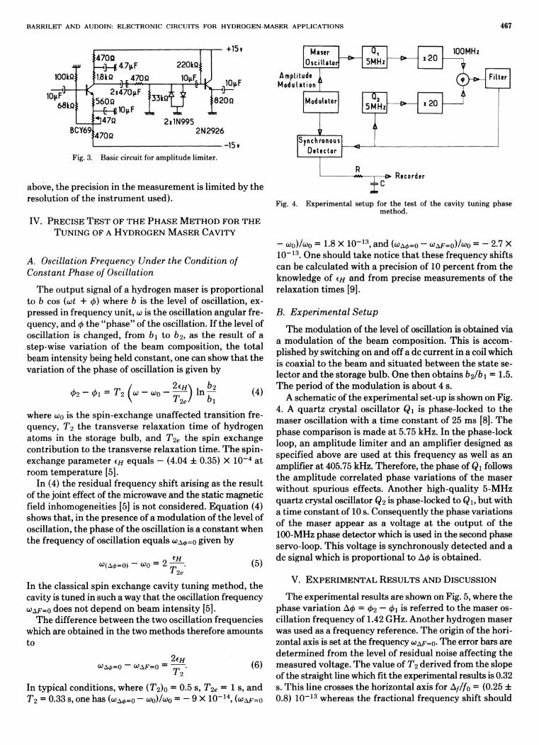
Fig. 3 shows the basic l imiter circuit which has been designed for operation a t 5.75 kHz. T h e clipping diodes are ma tched poin t -contac t diodes. T h e 47-Ω poten t iometer in t h e emi t t e r circuit of Τ χ allows t h e ad jus tment of t he collector dc voltage a t t he value 0 ± 50 mV. Each ampli-t u d e l imiter includes six such stages and a common col-lector i npu t stage. T h e o u t p u t square-wave has an ampli-tude of 300 mV. I t is constant within 1 percent for an input sinewave voltage of 10 to 300-mV rms . T h e phase shift variation is smaller t h a n 10~ 2 degree in the same range (as
BARRILET A N D AUDOIN: ELECTRONIC CIRCUITS FOR H Y D R O G E N - M A S E R A P P L I C A T I O N S 467
Fig. 3. Basic circuit for amplitude limiter.
above, t he precision in t he m e a s u r e m e n t is l imited by the resolution of t he i n s t rumen t used) .
IV. PRECISE T E S T OF THE P H A S E M E T H O D FOR THE
T U N I N G OF A HYDROGEN M A S E R CAVITY
A. Oscillation Frequency Under the Condition of
Constant Phase of Oscillation
T h e ou tpu t signal of a hydrogen maser is propor t ional to b cos (œt + φ) where b is t h e level of oscillation, ex-pressed in frequency uni t , ω is t he oscillation angular fre-quency, and φ t he " p h a s e " of the oscillation. If the level of oscillation is changed, from b χ to b2, as t h e resul t of a step-wise variat ion of t he beam composit ion, t h e to ta l beam intensity being held constant , one can show t h a t the variation of t he phase of oscillation is given by
02 - φι = T2 (ω - ω0~ ~r) l n Ί~
\ He' bi
(4)
where coo is the spin-exchange unaffected t rans i t ion fre-quency, T2 t he t ransverse relaxat ion t ime of hydrogen a toms in the storage bulb , and T2e t he spin exchange contr ibut ion to t he t ransverse relaxat ion t ime. T h e spin-exchange pa ramete r e// equals — (4.04 ± 0.35) X 1 0 ~ 4 a t room t empera tu re [5].
In (4) the residual frequency shift arising as t h e resul t of the joint effect of the microwave and the static magnetic field inhomogeneit ies [5] is no t considered. E q u a t i o n (4) shows tha t , in t he presence of a modula t ion of t h e level of oscillation, t he phase of t h e oscillation is a cons tan t when the frequency of oscillation equals ωΔ(/>=ο given by
ω(Δ<£=0) — ω 0 - 2 2e
(5)
In the classical spin exchange cavity tun ing me thod , t h e cavity is tuned in such a way t h a t the oscillation frequency O>AF=O does no t depend on beam in tens i ty [5].
T h e difference between t he two oscillation frequencies which are obtained in the two methods therefore amoun t s to
&Αφ=0 ~ U±F=0 — ' 2eH
(6)
In typical condit ions, where (T 2 )o = 0.5 s, T2e = 1 s, a n d T2 = 0.33 s, one has (ω Δ ( / )=ο - ω 0 ) / ω 0 = — 9 X 1 0 ~ 1 4 , (O>AF=O
Maser Οι i 20 Oscillator 5MHi i20
Amplitude ^ Modulation
lOOMHz L — " 1 Γ — Ί
(φ)-Ε>- Filter
Modulator 5MHzj
Synchronous Detector
ι 20
Recorder
Fig. 4. Experimental setup for the test of the cavity tuning phase method.
- ω 0 ) / ω 0 = 1.8 Χ 1 0 " 1 3 , and (ωΑφ=ο " ^AF=O)/^O = - 2.7 X 1 0 ~ 1 3 . One should t ake notice t h a t these frequency shifts can be calculated with a precision of 10 percent from the knowledge of en and from precise measu remen t s of t he relaxat ion t imes [9].
B. Experimental Setup
T h e modulation of the level of oscillation is obtained via a modula t ion of t he beam composit ion. Th i s is accom-plished by switching on and off a dc current in a coil which is coaxial to t he beam and s i tua ted between t h e s ta te se-lector and t h e storage bu lb . One t h e n obtains 62/^1 = 1.5. T h e period of t he modula t ion is abou t 4 s.
A schematic of the experimental se t -up is shown on Fig. 4. A quar tz crystal oscillator Qi is phase-locked to t he maser oscillation wi th a t ime cons tan t of 25 ms [8]. T h e phase comparison is m a d e a t 5.75 kHz. In t he phase-lock loop, an ampl i tude l imiter and an amplifier designed as specified above are used a t th is frequency as well as an amplifier a t 405.75 kHz. Therefore, the phase of Qi follows t h e ampl i tude correlated phase var iat ions of t he maser wi thout spurious effects. Another high-qual i ty 5-MHz quar tz crystal oscillator Q2 is phase-locked to Qi , bu t with a t ime constant of 10 s. Consequent ly the phase variations of t he maser appear as a voltage a t t he ou tpu t of t he 100-MHz phase detector which is used in the second phase servo-loop. Th i s voltage is synchronously de tec ted and a dc signal which is propor t ional to Αφ is obta ined.
V . EXPERIMENTAL R E S U L T S AND DISCUSSION
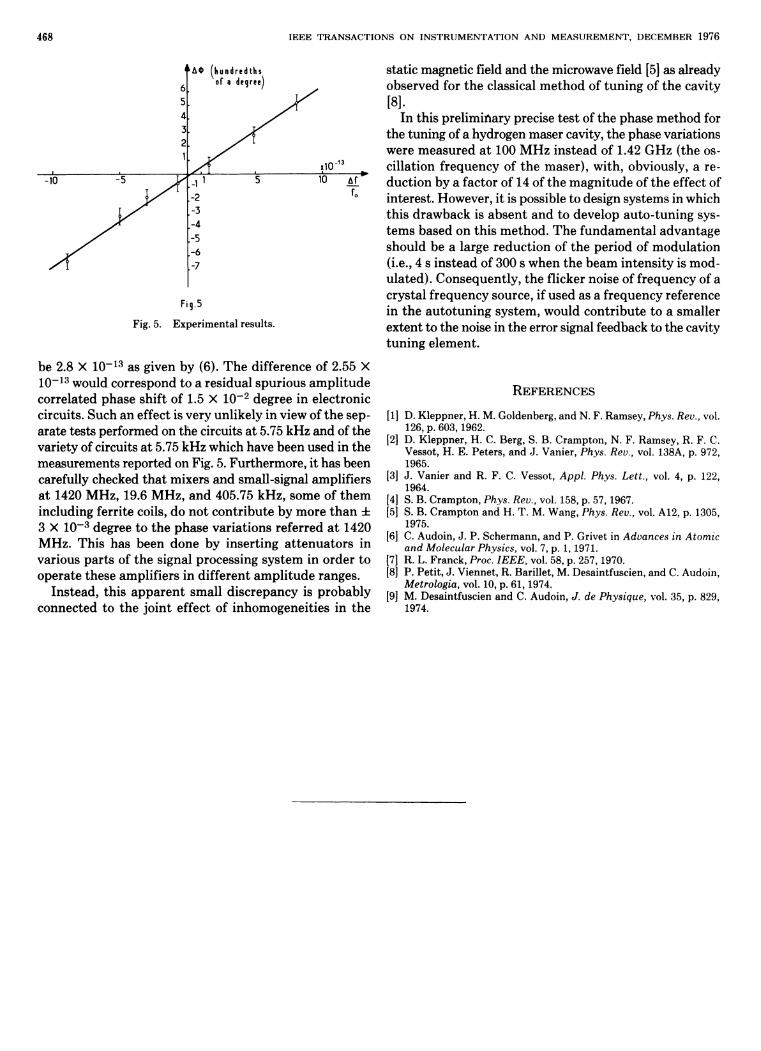
T h e experimental results are shown on Fig. 5, where the phase variat ion Αφ = φ2 — Φι is referred to the maser os-cillation frequency of 1.42 GHz. Another hydrogen maser was used as a frequency reference. T h e origin of t he hori-zontal axis is set a t the frequency ü>AF=O- T h e error bars are de te rmined from t h e level of residual noise affecting t he measured voltage. T h e value of T2 derived from the slope of the straight line which fit the experimental results is 0.32 s. Th i s line crosses t he horizontal axis for Δ///0 = (0.25 ± 0.8) 1 0 ~ 1 3 whereas the fractional frequency shift should
468 IEEE T R A N S A C T I O N S ON I N S T R U M E N T A T I O N A N D M E A S U R E M E N T , D E C E M B E R 1976
Fig.5
Fig. 5. Experimental results.
be 2.8 X 1 0 " 1 3 as given by (6). T h e difference of 2.55 X 1 0 ~ 1 3 would correspond to a residual spur ious ampl i tude correlated phase shift of 1.5 X 10~ 2 degree in electronic circuits. Such an effect is very unlikely in view of t h e sep-arate tests performed on the circuits a t 5.75 kHz and of the variety of circuits a t 5.75 kHz which have been used in the measurements reported on Fig. 5. Fur thermore, it has been carefully checked t h a t mixers and small-signal amplifiers a t 1420 MHz , 19.6 M Hz , and 405.75 kHz , some of t h e m including ferrite coils, do no t con t r ibu te by more t h a n ± 3 X 10~ 3 degree to the phase var ia t ions referred a t 1420 MHz. This has been done by insert ing a t t enua to r s in various par t s of t he signal processing system in order to opera te these amplifiers in different ampl i tude ranges.
Ins tead, th is a p p a r e n t small discrepancy is probably connected to t he jo in t effect of inhomogenei t ies in the
static magnetic field and the microwave field [5] as already observed for t h e classical me thod of tun ing of t he cavity [8].
In this prel iminary precise tes t of t he phase method for the tuning of a hydrogen maser cavity, the phase variations were measured a t 100 M H z ins tead of 1.42 GHz (the os-cillation frequency of t h e maser) , with, obviously, a re-duct ion by a factor of 14 of the magn i tude of t he effect of interest . However, it is possible to design systems in which th is d rawback is absen t and to develop au to- tun ing sys-t ems based on th is me thod . T h e fundamenta l advantage should be a large reduct ion of the period of modula t ion (i.e., 4 s ins tead of 300 s when the beam intensi ty is mod-ula ted) . Consequent ly , t he flicker noise of frequency of a crystal frequency source, if used as a frequency reference in t he au to tun ing system, would cont r ibute to a smaller extent to the noise in the error signal feedback to the cavity tun ing e lement .
REFERENCES
[1] D. Kleppner, H. M. Goldenberg, and N. F. Ramsey, Phys. Rev., vol. 126, p. 603,1962.
[2] D. Kleppner, H. C. Berg, S. B. Crampton, Ν. F. Ramsey, R. F. C Vessot, Η. Ε. Peters, and J. Vanier, Phys. Reu., vol. 138A, p. 972, 1965.
[3] J. Vanier and R. F. C. Vessot, Appl. Phys. Lett., vol. 4, p. 122, 1964.
[4] S. B. Crampton, Phys. Reu., vol. 158, p. 57,1967. [5] S. B. Crampton and H. T. M. Wang, Phys. Rev., vol. A12, p. 1305,
1975. [6] C. Audoin, J. P. Schermann, and P. Grivet in Advances in Atomic
and Molecular Physics, vol. 7, p. 1, 1971. [7] R. L. Franck, Proc. IEEE, vol. 58, p. 257,1970. [8] P. Petit, J. Viennet, R. Barillet, M. Desaintfuscien, and C. Audoin,
Metrologia, vol. 10, p. 61,1974. [9] M. Desaintfuscien and C. Audoin, J. de Physique, vol. 35, p. 829,
1974.