Embed Size (px)
Citation preview
alle
Maß
e in
mm
DimensionsAbmessungen
Technische Daten Technical data
Elektrischer Anschluss Electrical connection Adressen/Addresses
Sicherheitshinweise:• Vor der Inbetriebnahme Betriebsanleitung lesen• Anschluss, Montage und Einstellung nur durch Fachpersonal• Kein Sicherheitsbauteil gemäß EU-Maschinenrichtlinie
Security Instructions:• Read the operating instructions before attempting commissioning• Installation, connection and adjustments should only be undertaken by specialist personnel• Not a safety component in accordan ce with the EU Machinery Directive
all d
imen
sions
in m
m
88
102
116
62
93
12
18
754
.9
2
25.8
9
9.8
M12
23.8
10
54.6
ø 5.2
14.8
54.3
8
Allgemeine Daten
Messbereich 0,2 ... 50 m
Referenzobjekt OFR-100/100
Lichtsender Laserdiode typ. Lebensdauer 85.000 h bei Ta = +25 °C
Lichtart rot, Wechsellicht
Laserkenndaten
Hinweis LASERLICHT , NICHT IN DEN STRAHL BLICKEN
Laserklasse 2
Wellenlänge 660 nm
Strahldivergenz 1 mrad
Impulsdauer 5 ns
Wiederholrate 250 kHz
max. Puls Energie < 4 nJ
Winkelabweichung max. ± 2°
Messverfahren Pulse Ranging Technology (PRT)
Licht�eckdurchmesser < 50 mm im Abstand von 50 m bei 20 °C
Fremdlichtgrenze 50000 Lux
Temperaturein�uss typ. ≤ 0,25 mm/K
Kenndaten funktionale Sicherheit
MTTFd 200 a
Gebrauchsdauer (TM) 10 a
Diagnosedeckungsgrad (DC) 0 %
Anzeigen/Bedienelemente
Betriebsanzeige LED grün
Funktionsanzeige 2 LEDs gelb für Schaltzustand
Teach-In-Anzeige Teach-In: LEDs gelb/grün; gleichphasiges Blinken; 2,5 Hz Teach Fehler: LEDs gelb/grün; gegenphasiges Blinken; 8,0 Hz
Bedienelemente 5-stu�ger Drehschalter zur Auswahl der Betriebsmodi (Schaltschwelleneinstellung und Betrieb)
Bedienelemente Taster zum Setzen von Schwellwerten
Elektrische Daten
Betriebsspannung UB 10 ... 30 V DC / bei einem Betrieb im IO-Link-Modus: 1 8 ... 30 V
Welligkeit 10 % innerhalb der Versorgungstoleranz
Leerlaufstrom I0 ≤ 70 mA / 24 V DC
Ausgang
Signalausgang Gegentaktausgang, kurzschlussfest, verpolgeschützt
Schaltspannung max. 30 V DC
Schaltstrom max. 100 mA
Messausgang 1 Analogausgang 4 ... 20 mA, kurzschluss-/überlastfest, 12 Bit D/A
Schaltfrequenz f 50 Hz
Ansprechzeit 10 ms
Messgenauigkeit
Absolute Genauigkeit ± 25 mm
Reproduzierbarkeit < 5 mm
Umgebungsbedingungen
Umgebungstemperatur -30 ... 50 °C (-22 ... 122 °F)
Lagertemperatur -30 ... 70 °C (-22 ... 15 8 °F)
Mechanische Daten
Schutzart IP65
Anschluss Gerätestecker M12 x 1, 4-polig
Material
Gehäuse Kunststo� ABS
Lichtaustritt Kunststo�scheibe
Masse 90 g
Normen- und Richtlinienkonformität
Richtlinienkonformität EMV-Richtlinie 2004/10 8/EG
Normenkonformität
Produktnorm EN 60947-5-2:2007 IEC 60947-5-2:2007
Laserklasse IEC 60 825-1:2007 Complies with 21 CFR 1040.10 and 1040.11 except for deviations pursuant to Laser Notice No. 50, dated June 24, 2007
Zulassungen und Zerti�kate
Schutzklasse II, Bemessungsspannung ≤ 250 V AC bei Verschmutzungsgrad 1-2 nach IEC 60664-1
88
102
116
62
93
12
18
754
.9
2
25.8
9
9.8
M12
23.8
10
54.6
ø 5.2
14.8
54.3
8
Option:
2
1
3
4
+UB
C/Q1
0 V
Q2Analog
Option:
2
1
3
4
+UB
C/Q1
0 V
Q2analog
General speci�cations
Measurement range 0.2 ... 50 m
Reference target OFR-100/100
Light source laser diode typ. service life 85,000 h at Ta = +25 °C
Light type modulated visible red light
Laser nominal ratings
Note LASER LIGHT , DO NOT STARE INTO BEAM
Laser class 2
wave length 660 nm
Beam divergence 1 mrad
Pulse length 5 ns
Repetition rate 250 kHz
max. pulse energy < 4 nJ
Angle deviation max. ± 2°
Measuring method Pulse Ranging Technology (PRT)
Diameter of the light spot < 50 mm at a distance of 50 m at 20 °C
Ambient light limit 50000 Lux
Temperature in�uence typ. ≤ 0.25 mm/K
Functional safety related parameters
MTTFd 200 a
Mission Time (TM) 10 a
Diagnostic Coverage (DC) 0 %
Indicators/operating means
Operating display LED green
Function display 2 LEDs yellow for switching state
TEACH-IN indication TEACH-IN: LED green/yellow equiphase �ashing; 2.5 Hz Teach Error:LED green/yellow non equiphase �ashing; 8.0 Hz
Controls 5-step rotary switch for operating modes selection (threshold setting and operating modes)
Controls Switch for setting the threshold values
Electrical speci�cations
Operating voltage UB 10 ... 30 V DC / when operating in IO-Link mode: 1 8 ... 30 V
Ripple 10 % within the supply tolerance
No-load supply current I0 ≤ 70 mA / 24 V DC
Output
Signal output Push-pull output, short-circuit proof, protected against reverse polarity
Switching voltage max. 30 V DC
Switching current max. 100 mA
Measurement output 1 analog output 4 ... 20 mA, short-circuit/overload protected, 12 bit D/A
Switching frequency f 50 Hz
Response time 10 ms
Performance characteristics
Absolute accuracy ± 25 mm
Repeat accuracy < 5 mm
Ambient conditions
Ambient temperature -30 ... 50 °C (-22 ... 122 °F)
Storage temperature -30 ... 70 °C (-22 ... 15 8 °F)
Mechanical speci�cations
Protection degree IP65
Connection connector M12 x 1, 4-pin
Material
Housing Plastic ABS
Optical face Plastic pane
Mass 90 g
Compliance with standards and directives
Directive conformity EMC Directive 2004/10 8/EC
Standard conformity
Product standard EN 60947-5-2:2007 IEC 60947-5-2:2007
Laser class IEC 60 825-1:2007 Complies with 21 CFR 1040.10 and 1040.11 except for deviations pursuant to Laser Notice No. 50, dated June 24, 2007
Approvals and certi�cates
Protection class II, rated voltage ≤ 250 V AC with pollution degree 1-2 according to IEC 60664-1
= Hellschalt ung= D unkelschalt ung
= Light on= Dark on
Distanzsensor
mit Gerätestecker M12 x 1, 4-polig
Distance sensor
with 4-pin, M12 x 1 connector
MICRO-EPSILON MESSTECHNIK GmbH & Co. KGKönigbacher Str. 15 94496 Ortenburg / Deutschland
Tel. +49 (0) 8542 / 168-0 Fax +49 (0) 8542 / 168-90
optoNCDT ILR 1031-50
1 34
2 Kabelbuchse, Sicht auf Buchsenseite
Female cable connector,view on connector side
LASERLICHTLASER LIGHT
NICHT IN DEN STRAHL BLICKENDO NOT STARE INTO BEAM
LASER KLASSE 2CLASS 2 LASER PRODUCT
• Die Bestrahlung kann zu Irritationen gerade bei dunkler Umgebung führen. Nicht auf Menschen richten!• Vorsicht: Laserlicht, nicht in den Strahl blicken!• Wartung und Reparaturen nur von autorisiertem Servicepersonal durchführen lassen!• Das Gerät ist so anzubringen, dass die Warnhinweise deutlich sichtbar und lesbar sind.• Vorsicht: Wenn andere als die hier angegebenen Bedienungs- oder Justiereinrichtungen benutzt oder
andere Verfahrensweisen ausgeführt werden, kann dies zu gefährlicher Strahlungseinwirkung führen.
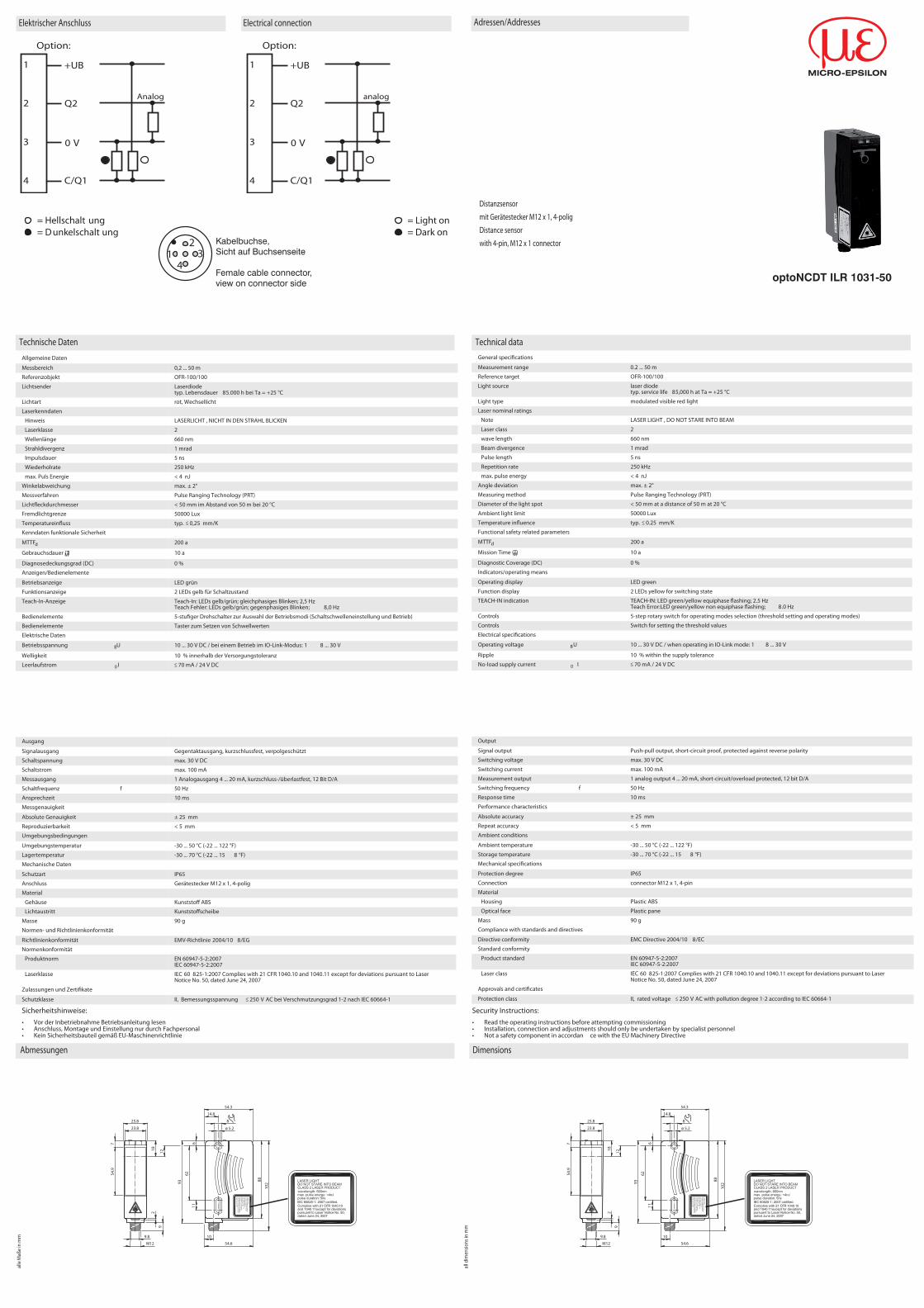
Teach-In:Sie können mit dem Drehschalter für den Schaltausgang Q1 die jeweilige Schaltschwelle A und/oder B wählen.Die gelben LEDs signalisieren den aktuellen Zustand des angewählten Ausgangs.
Zur Speicherung der Schaltschwelle (Entfernungsmesswert) drücken Sie die "SET"-Taste bis die LEDs gleich-phasig blinken (ca. 2 s). Das Teach-In beginnt mit dem Loslassen der "SET"-Taste. Ein erfolgreiches Teach-In wird durch wechselseitiges Blinken (2,5 Hz) der gelben und grünen LED signalisiert.
Ein fehlerhaftes Teachen wird durch wechselseitiges Blinken (8 Hz) signalisiert.
Nach dem erfolgreichen Teach-In wechseln Ausgang und LED ihren Zustand.Nach einem fehlerhaften Teach-In arbeitet der Sensor nach der entsprechenden Fehlermeldung mit seiner letz-ten gültigen Einstellung weiter.
Dieses Vorgehen kann für alle Schaltpunkte wiederholt werden.
Durch die Wahl der Schaltpunkte können verschiedene Schaltmodi angewählt werden:
Jeder geteachte Wert kann durch nochmaliges Drücken der SET-Taste nachgeteacht, d.h. überschrieben wer-den.
Durch Drücken der "SET"-Taste für > 5 s wird der an gewählte Teach-Wert gelöscht. Dies wird durch dasgleichzeitige Verlöschen der LEDs signalisiert.Das Einlernen von Minimalwert und Maximalwert für den Analogausgang Q2 erfolgt in der gleichen Weise wiebeim Schaltausgang:Dabei gilt: A = 4 mA
B = 20 mADadurch ergeben sich drei verschiedene Betriebsmöglichkeiten:A < B -> steigende Rampe
A > B -> fallende Rampe
A leer -> Nullpunktgerade
Werkseinstellung Analogausgang Q2:A = 200 mmB = 5000 mm
Zurücksetzen auf Werkseinstellung:• Stellen Sie den Drehschalter in Stellung "Run"• Drücken Sie die "SET"-Taste bis das gleichphasige Blinken der LED aufhört (ca. 10 s)• Wenn die grüne LED leuchtet, ist der Vorgang abgeschlossen.
Fehlermeldungen:• Kurzschluss: Im Falle eines Kurzschlusses blinkt die grüne LED mit einer Frequenz von ca. 4 Hz.
• Teach-Error: Im Falle eines Teach-Errors blinken beide LEDs abwechselt mit einer Frequenz von ca. 8 Hz.
Laserhinweis Laserklasse 2
Einstellungen
Ein löschen von Wert B ist nicht möglich.Die Betriebsart „Nullpunktgerade“ erhält man durch löschen von Wert A
• The irradiation can lead to irritation even in a dark environment. Do not point at people!• Caution: Do not look into the beam!• Maintenance and repairs should only be carr ied out by authorized service personnel!• Attach the device so that the warning is clearly visible and readable.• Caution – Use of controls or adjustments or performance of procedures other than those speci�ed herein
may result in hazardous radiation exposure.
Teach-inWith the rotary switch, you can select output Q1 and the relevant switching threshold A and/or B.The yellow LEDs indicate the current state of the selected output.
To store the switching threshold (d istance value) press the "SET" button until the LEDs �ash in phase
Laser notice laser class 2
Adjustment
B A
A > B
A B
B > A
B
A leer
A
B leer
4
20
BA
4
20
AB
4
20
B
(approx. 2 s). Teach-in starts when the "SET" button is released. Successful teach-in is indicated by alternating �ashing (2.5 Hz) of the yellow and green LEDs.
Unsuccessful teach-in is indicated by alternating �ashing (8 Hz).
After successful teach-in, the output and LED change their status.After unsuccessful teach-in, the sensor continues to operate with the previous valid setting after the relevanterror message is issued.
This procedure can be repeated for all switching points.
Di�erent switching modes can be selected by choosing di�erent switching points.
Every taught-in value can be re-taught (overwritten) by pressing the SET button again.
By pressing the "SET" button for > 5 s, the taught-in value is deleted. This procedure is indicated when theLEDs go out simultaneously.The teach-in of the minimum and maximum value for the analog output Q2 is set in the same way as the swit-ching output:For: A = 4 mA
B = 20 mAWith this three di�erent modes are achieved:A < B -> rising slope
A > B -> falling slope
A leer -> zero point straight
Default setting analog output Q2A = 200 mmB = 5000 mm
Reset to default settings• Set the rotary switch to the "RUN" position.• Press the "SET" button until the in-phase �ashing of the LEDs stops (approx. 10 s)• If the green LED lights up, the procedure is complete.
Error messages• Short circuit In the event of a short circuit, the green LED �ashes with a frequency of approx. 4 Hz.
• Teach error: In the event of a teach error, both LEDs �ash alternately with a frequency of approx. 8 Hz.
It is not possible to delete value B.By deleting value A you reach mode „zero point straight“
A no load
B no load
B A
A > B
A B
B > A
B A
4
20
BA
4
20
AB
4
20
B


![FMC son presentation [Uyumluluk Modu]donar.messe.de/exhibitor/hannovermesse/2017/M939034/fmc...FMC Hidrolik Sistemleri Otomotiv Mak. San. ve Tic. Ltd. Sti. Adres :Konya Organize Sanayi](https://img.pdfslide.org/doc/110x75/6097387ea539eb4fde0e18b5/fmc-son-presentation-uyumluluk-modudonarmessedeexhibitorhannovermesse2017m939034fmc.jpg)