Embed Size (px)
Citation preview
EN
Texte zu den geplanten neuen EU-Regelungen zur umwelt-
gerechten Produktgestaltung und zur Energieverbrauchs-
kennzeichnung in der Beleuchtung – Zusammenstellung *
des Umweltbundesamtes (UBA), Deutschland
Entwürfe der EU-Kommission vom 8. Oktober 2018
Entwurf der EU-Kommission für eine Regelung mit
Anforderungen an die Produktgestaltung
bei Lichtquellen und Betriebsgeräten
– Anhang –
Hinweis: Bitte beachten Sie, daß der angehängte Text nur in Englisch verfaßt ist. Vorangestellt ist aber ein
vom UBA eingefügtes Inhaltsverzeichnis in Deutsch.
EN: Information on the coming EU Lighting Regulations – Ecodesign and Energy Labelling
– Compilation * of the Federal Environment Agency (UBA), Germany
The EU Commission's drafts of 8 October 2018
Draft of the EU Commission for a regulation with requirements on the design of light sources and control gear
– Annex –
Notice: A content list has been added by UBA.
FR: Informations sur les futures réglementations de l‘UE concernant l’éclairage –
l’écoconception et l’étiquetage énergétique – Compilation * de l’Agence Fédérale de
l'Environnement (UBA), Allemagne
Les projets de la Commission Européenne du 8 octobre 2018
Projet de la Commission Européenne pour une réglementation des exigences de la conception des sources lumineuses et des appareillages de
commande
– Annexe –
Indication : Veuillez noter que le présent texte n'est disponible qu'en anglais. Mais antéposé par l'UBA, il y a
une table des matières en français.
* https://www.eup-network.de/de/eup-netzwerk-deutschland/offenes-forum-eu-regelungen-beleuchtung/dokumente/texte/
II
DE: ↓ EN: → page IV FR : → page VI
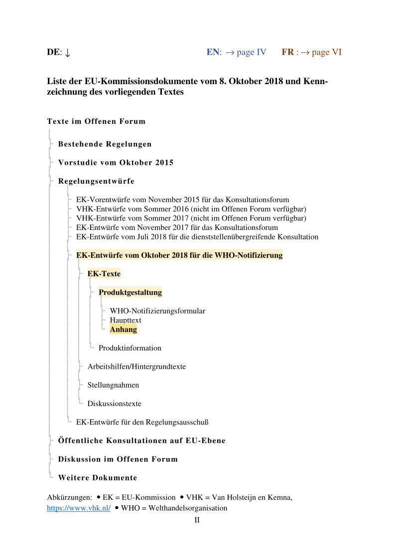
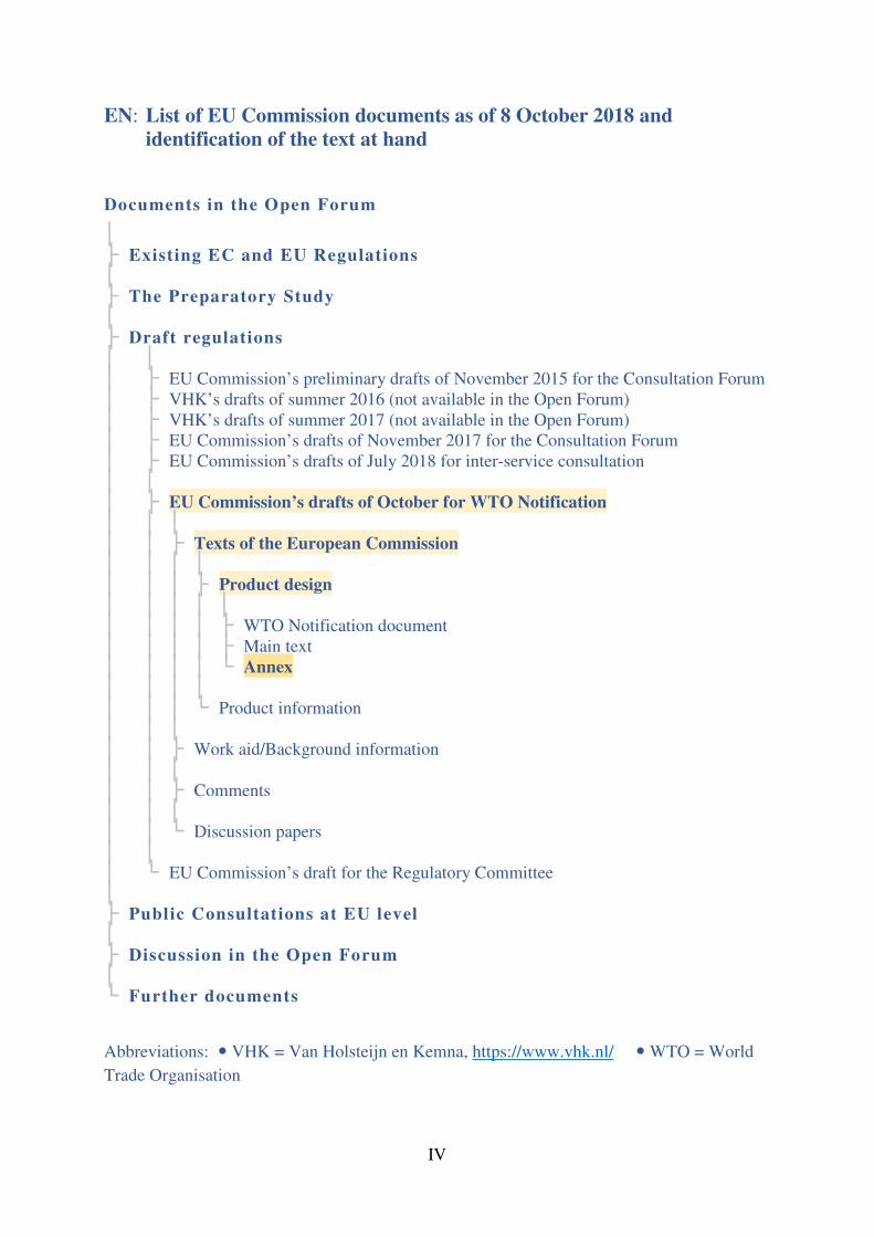
Liste der EU-Kommissionsdokumente vom 8. Oktober 2018 und Kenn-zeichnung des vorliegenden Textes
Texte im Offenen Forum
│ ├ Bestehende Regelungen │ ├ Vorstudie vom Oktober 2015 │ ├ Regelungsentwürfe │ │ │ ├ EK-Vorentwürfe vom November 2015 für das Konsultationsforum │ ├ VHK-Entwürfe vom Sommer 2016 (nicht im Offenen Forum verfügbar) │ ├ VHK-Entwürfe vom Sommer 2017 (nicht im Offenen Forum verfügbar) │ ├ EK-Entwürfe vom November 2017 für das Konsultationsforum │ ├ EK-Entwürfe vom Juli 2018 für die dienststellenübergreifende Konsultation │ │ │ ├ EK-Entwürfe vom Oktober 2018 für die WHO-Notifizierung │ │ │ │ │ ├ EK-Texte │ │ │ │ │ │ │ ├ Produktgestaltung │ │ │ │ │ │ │ │ │ ├ WHO-Notifizierungsformular │ │ │ │ ├ Haupttext │ │ │ │ └ Anhang │ │ │ │ │ │ │ └ Produktinformation │ │ │ │ │ ├ Arbeitshilfen/Hintergrundtexte │ │ │ │ │ ├ Stellungnahmen │ │ │ │ │ └ Diskussionstexte │ │ │ └ EK-Entwürfe für den Regelungsausschuß │ ├ Öffentliche Konsultationen auf EU-Ebene │ ├ Diskussion im Offenen Forum │ └ Weitere Dokumente Abkürzungen: EK = EU-Kommission VHK = Van Holsteijn en Kemna,
https://www.vhk.nl/ WHO = Welthandelsorganisation
III
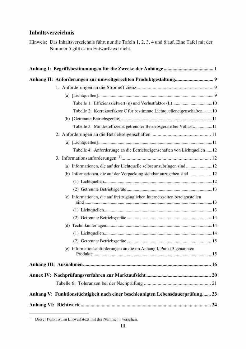
Inhaltsverzeichnis
Hinweis: Das Inhaltsverzeichnis führt nur die Tafeln 1, 2, 3, 4 und 6 auf. Eine Tafel mit der
Nummer 5 gibt es im Entwurfstext nicht.
Anhang I: Begriffsbestimmungen für die Zwecke der Anhänge ........................................ 1
Anhang II: Anforderungen zur umweltgerechten Produktgestaltung ............................... 9
1. Anforderungen an die Stromeffizienz .............................................................. 9
(a) [Lichtquellen] ......................................................................................................9
Tabelle 1: Effizienzzielwert (η) und Verlustfaktor (L) ...................................10
Tabelle 2: Korrekturfaktor C für bestimmte Lichtquelleneigenschaften ........10
(b) [Getrennte Betriebsgeräte] ................................................................................11
Tabelle 3: Mindesteffizienz getrennter Betriebsgeräte bei Vollast .................11
2. Anforderungen an die Betriebseigenschaften ................................................ 11
(a) [Lichtquellen] ....................................................................................................11
Tabelle 4: Anforderunge an die Betriebseigenschaften von Lichtquellen ......12
3. Informationsanforderungen [1]........................................................................ 12
(a) Informationen, die auf der Lichtquelle selbst anzubringen sind .......................12
(b) Informationen, die auf der Verpackung sichtbar anzugeben sind .....................12
(1) Lichtquellen ...............................................................................................12
(2) Getrennte Betriebsgeräte ...........................................................................13
(c) Informationen, die auf frei zugänglichen Internetzseiten bereitzustellen sind ................................................................................................................13
(1) Lichtquellen ...............................................................................................13
(2) Getrennte Betriebsgeräte ...........................................................................14
(d) Technikunterlagen.............................................................................................14
(1) Lichtquellen ...............................................................................................14
(2) Getrennte Betriebsgeräte ...........................................................................15
(e) Informationsanforderungen an die im Anhang I, Punkt 3 genannten Produkte ........................................................................................................15
Anhang III: Ausnahmen ....................................................................................................... 16
Annex IV: Nachprüfungsverfahren zur Marktaufsicht .................................................... 20
Tabelle 6: Toleranzen bei der Nachprüfung ...................................................... 21
Anhang V: Funktionstüchtigkeit nach einer beschleunigten Lebensdauerprüfung ....... 23
Anhang VI: Richtwerte ......................................................................................................... 24
1 Dieser Punkt ist im Entwurfstext mit der Nummer 1 versehen.
IV
EN: List of EU Commission documents as of 8 October 2018 and identification of the text at hand
Documents in the Open Forum
│ ├ Existing EC and EU Regulations │ ├ The Preparatory Study │ ├ Draft regulations │ │ │ ├ EU Commission’s preliminary drafts of November 2015 for the Consultation Forum │ ├ VHK’s drafts of summer 2016 (not available in the Open Forum) │ ├ VHK’s drafts of summer 2017 (not available in the Open Forum) │ ├ EU Commission’s drafts of November 2017 for the Consultation Forum │ ├ EU Commission’s drafts of July 2018 for inter-service consultation │ │ │ ├ EU Commission’s drafts of October for WTO Notification │ │ │ │ │ ├ Texts of the European Commission │ │ │ │ │ │ │ ├ Product design │ │ │ │ │ │ │ │ │ ├ WTO Notification document │ │ │ │ ├ Main text │ │ │ │ └ Annex │ │ │ │ │ │ │ └ Product information │ │ │ │ │ ├ Work aid/Background information │ │ │ │ │ ├ Comments │ │ │ │ │ └ Discussion papers │ │ │ └ EU Commission’s draft for the Regulatory Committee │ ├ Public Consultations at EU level │ ├ Discussion in the Open Forum │ └ Further documents
Abbreviations: VHK = Van Holsteijn en Kemna, https://www.vhk.nl/ WTO = World
Trade Organisation
V
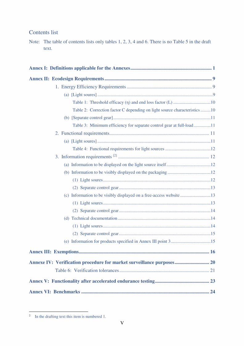
Contents list
Note: The table of contents lists only tables 1, 2, 3, 4 and 6. There is no Table 5 in the draft
text.
Annex I: Definitions applicable for the Annexes .................................................................. 1
Annex II: Ecodesign Requirements ....................................................................................... 9
1. Energy Efficiency Requirements ..................................................................... 9
(a) [Light soures] ......................................................................................................9
Table 1: Threshold efficacy (η) and end loss factor (L) .................................10
Table 2: Correction factor C depending on light source characteristics .........10
(b) [Separate control gear] ......................................................................................11
Table 3: Minimum efficiency for separate control gear at full-load ...............11
2. Functional requirements ................................................................................. 11
(a) [Light soures] ....................................................................................................11
Table 4: Functional requirements for light sources ........................................12
3. Information requirements [2] .......................................................................... 12
(a) Information to be displayed on the light source itself .......................................12
(b) Information to be visibly displayed on the packaging ......................................12
(1) Light soures ...............................................................................................12
(2) Separate control gear .................................................................................13
(c) Information to be visibly displayed on a free-access website ...........................13
(1) Light soures ...............................................................................................13
(2) Separate control gear .................................................................................14
(d) Technical documentation ..................................................................................14
(1) Light soures ...............................................................................................14
(2) Separate control gear .................................................................................15
(e) Information for products specified in Annex III point 3 ...................................15
Annex III: Exemptions .......................................................................................................... 16
Annexe IV: Verification procedure for market surveillance purposes ............................ 20
Table 6: Verification tolerances ......................................................................... 21
Annex V: Functionality after accelerated endurance testing ............................................ 23
Annex VI: Benchmarks ........................................................................................................ 24
2 In the drafting text this item is numbered 1.
VI
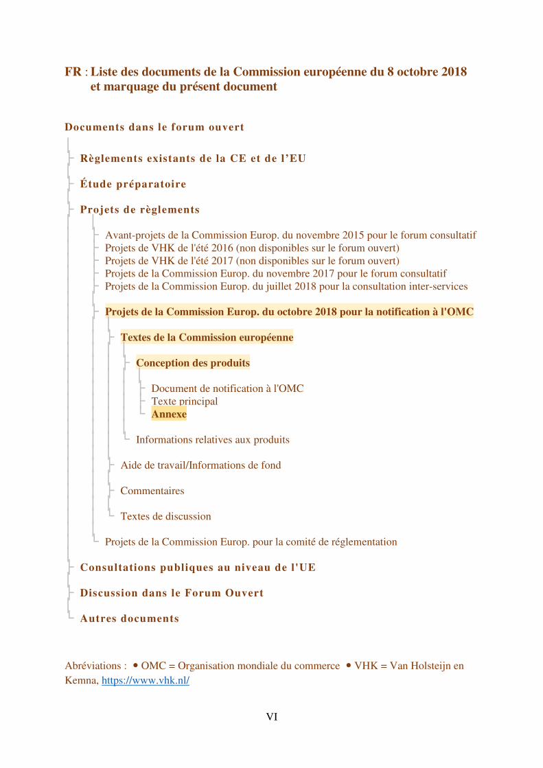
FR : Liste des documents de la Commission européenne du 8 octobre 2018 et marquage du présent document
Documents dans le forum ouvert
│ ├ Règlements existants de la CE et de l’EU │ ├ Étude préparatoire │ ├ Projets de règlements │ │ │ ├ Avant-projets de la Commission Europ. du novembre 2015 pour le forum consultatif │ ├ Projets de VHK de l'été 2016 (non disponibles sur le forum ouvert) │ ├ Projets de VHK de l'été 2017 (non disponibles sur le forum ouvert) │ ├ Projets de la Commission Europ. du novembre 2017 pour le forum consultatif │ ├ Projets de la Commission Europ. du juillet 2018 pour la consultation inter-services │ │ │ ├ Projets de la Commission Europ. du octobre 2018 pour la notification à l'OMC │ │ │ │ │ ├ Textes de la Commission européenne │ │ │ │ │ │ │ ├ Conception des produits │ │ │ │ │ │ │ │ │ ├ Document de notification à l'OMC │ │ │ │ ├ Texte principal │ │ │ │ └ Annexe │ │ │ │ │ │ │ └ Informations relatives aux produits │ │ │ │ │ ├ Aide de travail/Informations de fond │ │ │ │ │ ├ Commentaires │ │ │ │ │ └ Textes de discussion │ │ │ └ Projets de la Commission Europ. pour la comité de réglementation │ ├ Consultations publiques au niveau de l'UE │ ├ Discussion dans le Forum Ouvert │ └ Autres documents
Abréviations : OMC = Organisation mondiale du commerce VHK = Van Holsteijn en
Kemna, https://www.vhk.nl/
VII
Table des matières
Note : La table des matières répertorie uniquement les tableaux 1, 2, 3, 4 et 6. Il n'y a pas de
tableau 5 dans le projet de texte.
Annexe I: Définitions applicables aux fins des annexes ....................................................... 1
Annexe II: Exigences d'écoconception .................................................................................. 9
1. Exigences d’efficacité énergétique .................................................................. 9
(a) [Sources lumineuses] ..........................................................................................9
Tableau 1: Seuil d'efficacité (η) et facteur de perte (L) .................................10
Tableau 2: Facteur de correction C en fonction des propriétés de la source lumineuse ........................................................................................10
(b) [Appareillages de commande séparées] ............................................................11
Tableau 3: Efficacité minimales pour appareillages de commande séparées à pleine charge ..............................................................................11
2. Exigences fonctionnelles ................................................................................ 11
(a) [Sources lumineuses] ........................................................................................11
Tableau 4: Exigences de fonctionnalité applicables aux sources lumineuses ..................................................................................................12
3. Exigences d'information [3] ............................................................................ 12
(a) Informations à afficher sur la source lumineuse elle-même..............................12
(b) Informations à faire figurer de manière visible sur l’emballage .......................12
(1) Sources lumineuses ...................................................................................12
(2) Appareillages de commande séparées .......................................................13
(c) Informations à faire figurer de manière visible sur les sites internet en libre accès ......................................................................................................13
(1) Sources lumineuses ...................................................................................13
(2) Appareillages de commande séparées .......................................................14
(d) Documentation technique .................................................................................14
(1) Sources lumineuses ...................................................................................14
(2) Appareillages de commande séparées .......................................................15
(e) Exigences d'information applicables aux produits précisées à l'annexe I point 3 ............................................................................................................15
Annexe III: Exemptions ........................................................................................................ 16
Anhang V: Procédure de vérification aux fins de la surveillance du marché ................. 20
Tableau 6: Tolérances utilisées dans la vérification .......................................... 21
3 Cet article est numéroté 1 dans le projet.
VIII
Annexe V: Fonctionnalité après un test d'endurance accéléré ......................................... 23
Annexe VI: Critères de référence ........................................................................................ 24
Es folgt ein unveränderter Originaltext.
EN: The following is an unmodified original text.
FR: Ce qui suit est un texte original.
EN EN
EUROPEAN COMMISSION
Brussels, XXX
[…](2018) XXX draft
ANNEXES 1 to 6
ANNEXES
to the
COMMISSION REGULATION (EU) …/…
laying down ecodesign requirements for light sources and separate control gears
pursuant to Directive 2009/125/EC of the European Parliament and of the Council
repealing Commission Regulations (EC) No 244/2009, (EC) No 245/2009 and (EU) No
1194/2012
EN 1 EN
ANNEX I
Definitions applicable for the Annexes
The following definitions shall apply for the purposes of the Annexes:
(1) ‘mains light source (MLS)’ means a light source that can be operated directly on the
mains electricity supply. Light sources that operate directly on the mains, and can
also operate indirectly on the mains using a separate control gear, shall be considered
to be mains light sources;
(2) ‘non-mains light source (NMLS)’, means a light source that is not a mains light
source. These light sources require a separate control gear to operate on the mains;
(3) ‘directional light source’ (DLS) means a light source having at least 80 % of total
luminous flux within a solid angle of π sr (corresponding to a cone with angle of
120°);
(4) ‘non-directional light source’ (NDLS) means a light source that is not a directional
light source;
(5) ‘connected light source’ (CLS) means a light source including data-connection parts
that are physically or functionally inseparable from the light emitting parts to
maintain the ‘reference control settings’. The light source can have physically
integrated data-connection parts in a single inseparable housing, or the light source
can be combined with physically separate data-connection parts placed on the market
together with the light source as a single product.
(6) ‘connected separate control gear’ (CSCG) means a separate control gear including
data-connection parts that are physically or functionally inseparable from the actual
control gear parts to maintain the ‘reference control settings’. The separate control
gear can have physically integrated data-connection parts in a single inseparable
housing, or the separate control gear can be combined with physically separate data-
connection parts placed on the market together with the control gear as a single
product;
(7) ‘data-connection parts’ means parts that perform any one of the following functions:
(a) reception or transmission of wired or wireless data signals and the processing
thereof (used to control the light emission function and possibly otherwise);
(b) sensing and processing of the sensed signals (used to control the light emission
function and possibly otherwise);
(c) actuation by audio control (including voice control);
(d) a combination of these;
(8) ‘colour-tuneable light source’ (CTLS) means a light source that can be set to emit
light with a large variation of colours outside the range defined in Article 2 but can
also be set to emit white light inside the range defined in Article 2 for which the light
source is within the scope of this Regulation.
The term does not include tuneable-white light sources that can only be set to emit
light, with different correlated colour temperatures, within the range defined in
Article 2.
The term also does not include dim-to-warm light sources, that shift their white light
output to lower correlated colour temperature when dimmed, simulating the
behaviour of incandescent light sources;
EN 2 EN
(9) ‘colour purity index’ means a percentage computed for a CTLS set to emit light of a
certain colour, using a procedure further defined in standards, by drawing a straight
line on an (x and y) colour space graph from a point with colour coordinates x=0.313
and y=0.330 (D65 reference point, point 1), going through the point representing the
(x and y) colour coordinates of the light source (point 2), and ending on the outer
border of the colour space (locus; point 3). The colour purity index is computed as
the distance between points 1 and 2 divided by the distance between points 1 and 3.
The full length of the line represents 100 % colour purity (point on the locus). The
D65 reference point represents 0 % colour purity (white light);
(10) ‘lighting control parts’ means parts that are integrated in a light source or in a
separate control gear, or physically separated but marketed together with a light
source or separate control gear as a single product, that are not strictly necessary for
the light source to emit light at full-load, or for the separate control gear to supply the
electric power that enables light source(s) to emit light at full-load, but that enable
manual- or automatic-, direct- or remote-, control of luminous intensity,
chromaticity, correlated colour temperature, light spectrum and/or beam angle.
Dimmers shall also be considered as lighting control parts.
The term also includes data-connection parts, but the term does not include products
within the scope of Commission Regulation (EC) No 1275/20081;
(11) ‘non-lighting parts’ means parts that are integrated in a light source or in a separate
control gear, or physically separated but marketed together with a light source or
separate control gear as a single product, that are not necessary for the light source to
emit light at full-load, or for the separate control gear to supply the electric power
that enables light source(s) to emit light at full-load, and that are not ‘lighting control
parts’. Examples include, but are not limited to: speakers (audio), cameras, repeaters
for communication signals to extend the range (e.g. WiFi), parts supporting grid
balance (switching to own internal batteries when necessary), battery charging,
visual notification of events (mail arriving, door bell ringing, alert), use of Light
Fidelity (Li-Fi, a bidirectional, high-speed and fully networked wireless
communication technology);
(12) ‘useful luminous flux’ (Φuse), means the part of the luminous flux of a light source
that is considered when determining its energy efficiency:
– for non-directional light sources it is the total flux emitted in a solid angle of 4π
sr (corresponding to a 360˚ sphere);
– for directional light sources with beam angle ≥ 90° it is the flux emitted in a
solid angle of π sr (corresponding to a cone with angle of 120°);
– for directional light sources with beam angle < 90° it is the flux emitted in a
solid angle of 0.586π sr (corresponding to a cone with angle of 90°);
(13) ‘beam angle’ of a directional light source means the angle between two imaginary
lines in a plane through the optical beam axis, such that these lines pass through the
centre of the front face of the light source and through points at which the luminous
intensity is 50 % of the centre beam intensity, where the centre beam intensity is the
value of luminous intensity measured on the optical beam axis.
For light sources that have different beam angles in different planes, the largest beam
angle shall be the one taken into account;
1 OJ L 339, 18.12.2008, p. 45.
EN 3 EN
For light sources with user-controllable beam angle, the beam angle corresponding to
the ‘reference control setting’ shall be the one taken into account;
(14) ‘full-load’ means:
– the condition of a light source, within the declared operating conditions, in
which it emits the maximum (undimmed) initial luminous flux; or
– the operating conditions and loads of the control gear under efficiency
measurement as specified in the relevant standards;
(15) ‘no-load mode’ means the condition of a separate control gear in which its input is
connected to the mains power source and its output is intentionally disconnected
from light sources, and, if applicable, from data-connection parts, lighting control
parts and non-lighting parts. If these parts cannot be disconnected, they shall be
switched off and their power consumption shall be minimised following the
manufacturer’s instructions. No-load mode only applies to a separate control gear for
which the manufacturer or importer has declared in the technical documentation that
it has been designed for this mode;
(16) ‘standby mode’ means the condition of a light source or of a separate control gear,
where it is connected to the power supply but the light sources are intentionally not
emitting light, and the light source or control gear is awaiting a control signal (from a
source different from a network) to return to a state with light emission. Lighting
control parts enabling the standby function shall be in their control mode. Non-
lighting parts shall be disconnected or switched off or their power consumption shall
be minimised following manufacturer’s instructions;
(17) ‘networked standby mode’ means the condition of a connected light source (CLS) or
a connected separate control gear (CSCG) where it is connected to the power supply
but the light source is intentionally not emitting light or the control gear does not
supply the electric power that enables light source(s) to emit light, and is awaiting a
remotely initiated trigger to return to a state with light emission. Lighting control
parts shall be in their control mode. Non-lighting parts shall be disconnected or
switched off or their power consumption shall be minimised following
manufacturer’s instructions;
(18) ‘control mode’ means the condition of lighting control parts where they are
connected to the light source and/or to the separate control gear and performing their
functions in such a way that a control signal can be internally generated or a remotely
initiated trigger can be received, by wire or wireless, and processed to lead to a
change in the light emission of the light source or to a corresponding desired change
in the power supply by the separate control gear;
(19) ‘remotely initiated trigger’ means a signal that comes from outside the light source or
separate control gear via a network;
(20) ‘control signal’ means an analogue or digital signal transmitted to the light source or
separate control gear wirelessly or wired either via voltage modulation in separate
control cables or via a modulated signal in the supply voltage. The signal
transmission is not through a network but e.g. from an internal source or from a
remote control delivered with the product;
(21) ‘network’ means a communication infrastructure with a topology of links, an
architecture, including the physical components, organisational principles,
communication procedures and formats (protocols);
EN 4 EN
(22) ‘on-mode power’ (Pon), expressed in Watt, means the electric power consumption of
a light source in full-load with all lighting control parts and non-lighting parts
disconnected. If these parts cannot be disconnected, they shall be switched off or
their power consumption shall be minimised following the manufacturer’s
instructions. In case of a non-mains light source (NMLS) that requires a separate
control gear to operate, Pon can be measured directly on the input to the light source,
or Pon is determined using a control gear with known efficiency, whose electric
power consumption is subsequently subtracted from the measured mains power input
value;
(23) ‘no-load power’ (Pno), expressed in Watt, is the electric power consumption of a
separate control gear in no-load mode;
(24) ‘standby power’ (Psb), expressed in Watt, is the electric power consumption of a light
source or of a separate control gear in standby mode;
(25) ‘networked standby power’ (Pnet), expressed in Watt, is the electric power
consumption of a connected light source (CLS) or of a connected separate control
gear (CSCG) in networked standby mode;
(26) ‘reference control settings’ (RCS) means a control setting or a combination of
control settings that is used to verify compliance of a light source with this
Regulation. These settings are relevant for light sources that allow the end-user to
control, manually or automatically, directly or remotely, the luminous intensity,
colour, correlated colour temperature, spectrum, and/or beam angle of the emitted
light.
In principle, the reference control settings shall be those predefined by the
manufacturer as factory default values and encountered by the user at first
installation (out-of-the-box values). If the installation procedure provides for an
automatic software update during first installation, or if the user has the option to
perform such an update, the resulting change in settings (if any) shall be taken into
account.
If the out-of-the-box value is deliberately set differently from the reference control
setting (e.g. at low power for safety purposes), the manufacturer shall indicate in the
technical documentation how to recall the reference control settings for compliance
verification.
The light source manufacturer shall define the reference control settings such that:
– the light source is within the scope of this Regulation according to Article 1
and none of the conditions for exemption applies;
– lighting control parts and non-lighting parts are disconnected or switched-off
or, in case this is not possible, the power consumption of these parts is
minimal;
– the full-load condition is obtained;
– when the end-user opts to reset factory defaults, the reference control settings
are obtained.
For light sources that allow the manufacturer of a containing product to make
implementation choices that influence light source characteristics (e.g. definition of
the operating current(s); thermal design), and that cannot be controlled by the end-
EN 5 EN
user, the reference control settings need not be defined. In that case the nominal test
conditions as defined by the light source manufacturer apply;
(27) ‘high-pressure mercury light source’ means a high intensity discharge light source in
which the major portion of light is produced, directly or indirectly, by radiation from
predominantly vaporised mercury operating at a partial pressure in excess of 100
kilopascals;
(28) ‘metal halide light source’ (MH) means a high intensity discharge light source in
which the light is produced by radiation from a mixture of metallic vapour, metal
halides and the products of the dissociation of metal halides. MH light sources may
have one (‘single-ended’) or two (‘double-ended’) connectors to their electricity
supply. The material for the arc tube of MH light sources can be quartz (QMH) or
ceramic (CMH);
(29) ‘compact fluorescent light source’ (CFL) means a single-capped fluorescent light
source with a bent-tube construction designed to fit in small spaces. CFLs may be
primarily spiral-shaped (i.e. curly forms) or primarily shaped as connected multiple
parallel tubes, with or without a second bulb-like envelope. CFLs are available with
(CFLi) or without (CFLni) a physically integrated control gear;
(30) ‘T2’, ‘T5’, ‘T8’, ‘T9’ and ‘T12’ means a tubular light source with a diameter of
approximately 7, 16, 26, 29 and 38 mm respectively, as defined in standards. The
tube can be straight (linear) or bent (e.g. U-shaped, circular);
(31) ‘LFL T5-HE’ means a high-efficiency linear fluorescent T5 light source with driving
current lower than 0,2 A;
(32) ‘LFL T5-HO’ means a high-output linear fluorescent T5 light source with driving
current higher than or equal to 0,2 A;
(33) ‘LFL T8 2-foot’, ‘LFL T8 4-foot’ or ‘LFL T8 5-foot’ means a linear T8 fluorescent
light source with a length of approximately 600 mm (2 feet), 1200 mm (4 feet) or
1500 mm (5 feet) respectively, as defined in standards;
(34) ‘magnetic induction light source’ means a light source using fluorescent technology,
where energy is transferred to the gas discharge by means of an induced high-
frequency magnetic field, instead of using electrodes placed inside the gas discharge.
The magnetic inductor can be external or internal to the shape of the discharge tube;
(35) ‘G4’, ‘GY6.35’ and ‘G9’ means an electrical interface for a light source consisting of
two small pins at distances of 4, 6,35 and 9 mm respectively, as defined in standards;
(36) ‘HL R7s’ means a mains-voltage, double-capped, linear halogen light source with a
cap diameter of 7 mm;
(37) ‘G9.5’, ‘GX9.5’, ‘GY9.5’, ‘G9.5HPL’, ‘G16d’, ‘GX16d’, ‘GY16’, ‘G22’ and ‘G38’
means an electrical interface for a light source consisting of two pins at distances of
9.5, 16, 22 and 38 mm respectively, as defined in standards. ‘G9.5HPL’ includes a
heatsink of specific dimensions as used on high-performance halogen lamps, and
may include additional pins for grounding purposes;
(38) ‘P28s’, ‘P40s’ and ‘PGJX50’ means an electrical interface for a light source that uses
a flange contact to correctly position (pre-focus) the light source in a reflector, as
defined in standards;
(39) ‘QXL (Quick eXchange Lamp)’ means an electrical interface for a light source
consisting, on the light source side, of two lateral tabs including the electrical contact
EN 6 EN
surfaces and, on the opposite (rear) side, of a central protrusion allowing the light
source to be grabbed with two fingers. It has been specifically designed for use in a
class of stage lighting luminaires, in which the light source is inserted from the rear
of the luminaire using a one quarter turn rotation to fix or unfix it;
(40) ‘battery-operated’ means a product that operates only on direct current (DC) supplied
from a source contained in the same product, without being connected directly or
indirectly to the mains electricity supply;
(41) ‘second envelope’ means a second outer envelope on an HID light source that is not
required for the production of light, such as an external sleeve for preventing
mercury and glass release into the environment in case of lamp breakage. In
determining the presence of a second envelope, the HID arc tubes shall not count as
an envelope;
(42) ‘non-clear envelope’ for an HID light source means a non-transparent outer envelope
or outer tube in which the light producing arc tube is not visible;
(43) ‘anti-glare shield’ means a mechanical or optical reflective or non-reflective
impervious baffle designed to block direct visible radiation emitted from the light
emitter in a directional light source, in order to avoid temporary partial blindness
(disability glare) if viewed directly by an observer. It does not include surface
coating of the light emitter in the directional light source;
(44) ‘control gear efficiency’ is the output power that supplies a light source divided by
the input power of a separate control gear using the conditions and methods defined
in standards. Any lighting control parts and non-lighting parts are disconnected,
switched off or set to minimum power consumption according to manufacturer’s
instructions and subtracting this power consumption from the overall input power;
(45) ‘functionality after endurance testing’ means the functionality of a LED or OLED
light source after endurance testing as defined in Annex V;
(46) ‘flicker’ means the perception of visual unsteadiness induced by a light stimulus, the
luminance or spectral distribution of which fluctuates with time, for a static observer
in a static environment. The fluctuations can be periodic and non-periodic and may
be induced by the light source itself, the power source or other influencing factors.
The metric for flicker used in this Regulation is the parameter ‘Pst LM’, where ‘st’
stands for short term and ‘LM’ for light flickermeter method, as defined in standards.
A value Pst LM=1 means that the average observer has a 50 % probability of
detecting flicker;
(47) ‘stroboscopic effect’ means a change in motion perception induced by a light
stimulus, the luminance or spectral distribution of which fluctuates with time, for a
static observer in a non-static environment. The fluctuations can be periodic and non-
periodic and may be induced by the light source itself, the power source or other
influencing factors.
The metric for the stroboscopic effect used in this Regulation is the ‘SVM’
(stroboscopic visibility measure), as defined in standards. SVM = 1 represents the
visibility threshold for an average observer;
(48) ‘declared value’ for a parameter means the value given by the manufacturer or
importer in the technical documentation pursuant to point 2 of Annex IV to Directive
2009/125/EC;
EN 7 EN
(49) ‘specific effective radiant ultraviolet power’ (mW/klm) means the effective power of
the ultraviolet radiation of a light source weighted according to the spectral
correction factors and related to its luminous flux;
(50) ‘luminous intensity’ (candela or cd) means the quotient of the luminous flux leaving
the source and propagated in the element of solid angle containing a given direction,
by the element of solid angle;
(51) ‘correlated colour temperature’ (CCT [K]) means the temperature of a Planckian
(black body) radiator whose perceived colour most closely resembles that of a given
stimulus at the same brightness and under specified viewing conditions;
(52) ‘colour consistency’ means the maximum deviation of the initial (after a short period
of time), spatially averaged chromaticity coordinates (x and y) of a single light
source from the chromaticity centre point (cx and cy) declared by the manufacturer
or the importer, expressed as the size (in steps) of the MacAdam ellipse formed
around the chromaticity centre point (cx and cy);
(53) ‘displacement factor (cos φ1)’ means the cosine of the phase angle φ1 between the
fundamental harmonic of the mains supply voltage and the fundamental harmonic of
the mains current. It is used for mains light sources using LED- or OLED-
technology. The displacement factor is measured at full-load, for the reference
control settings where applicable, with any lighting control parts in control mode and
non-lighting parts disconnected, switched off or set to minimum power consumption
according to the manufacturer’s instructions;
(54) ‘lumen maintenance factor’ (LMF) means the ratio of the luminous flux emitted by a
light source at a given time in its life to the initial luminous flux;
(55) ‘survival factor’ (SF) means the defined fraction of the total number of light sources
that continue to operate at a given time under defined conditions and switching
frequency;
(56) ‘lifetime’ for LED and OLED light sources means the time in hours between the start
of their use and the moment when for 50 % of a population of light sources the light
output has gradually degraded to a value below 70 % of the initial luminous flux.
This is also referred to as the L70B50 lifetime;
(57) ‘equivalent model’ means a model with the same relevant technical and performance
characteristics as another model placed on the market under a different commercial
code;
(58) ‘end-user’ means a natural person buying or expected to buy a product for purposes
which are outside his trade, business, craft or profession;
(59) ‘photosensitive patients’ means people with a specific condition causing
photosensitive symptoms and who experience adverse reactions to natural and/or
certain forms of artificial lighting technology;
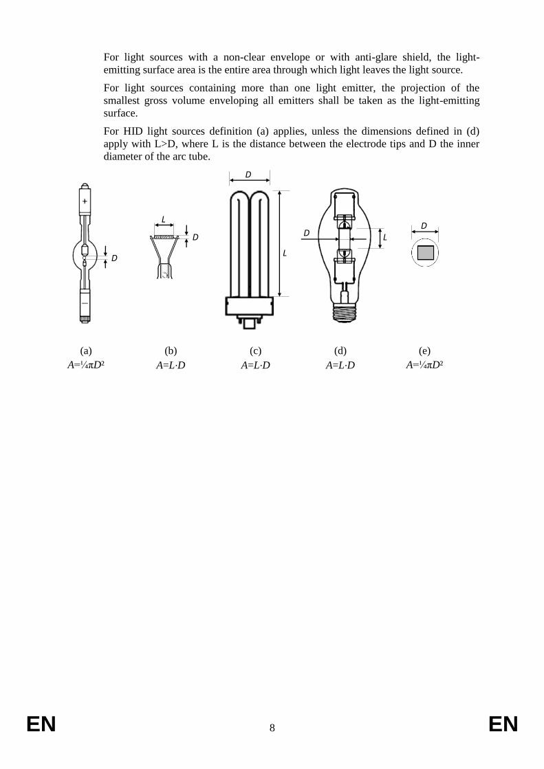
(60) ‘projected light-emitting surface area (A)’ is the surface area in mm² (square
millimetres) of the view in an orthographic projection of the light-emitting surface
from the direction with the highest light intensity, where the light-emitting surface
area is the surface area of the light source that emits light with the declared optical
characteristics, such as the approximately spherical surface of an arc (a), cylindrical
surface of a filament coil (b) or a gas discharge lamp (c, d), flat or semi-spherical
envelope of a light-emitting diode (e).
EN 8 EN
For light sources with a non-clear envelope or with anti-glare shield, the light-
emitting surface area is the entire area through which light leaves the light source.
For light sources containing more than one light emitter, the projection of the
smallest gross volume enveloping all emitters shall be taken as the light-emitting
surface.
For HID light sources definition (a) applies, unless the dimensions defined in (d)
apply with L>D, where L is the distance between the electrode tips and D the inner
diameter of the arc tube.
D
D
L D
D
L
D L
(a)
A=¼πD²
(e)
A=¼πD²
(b)
A=L∙D
(c)
A=L∙D
(d)
A=L∙D
EN 9 EN
ANNEX II
Ecodesign requirements
For the purposes of compliance and verification of compliance with the requirements of this
Regulation, measurements and calculations shall be made using harmonised standards the
reference numbers of which have been published for this purpose in the Official Journal of the
European Union, or other reliable, accurate and reproducible methods, which take into
account the generally recognised state-of-the-art.
1. Energy efficiency requirements:
(a) From 1 September 2021, the declared power consumption of a light source Pon shall
not exceed the maximum allowed power Ponmax (in W), defined as a function of the
declared useful luminous flux Φuse (in lm) and the declared colour rendering index
CRI (-) as follows:
Ponmax = C * (L + Φuse / (F*η)) * R
where:
– The values for threshold efficacy (η in lm/W) and end loss factor (L in W) are
specified in Table 1, depending on the light source type. They are constants
used for computations and do not reflect true parameters of light sources. The
threshold efficacy is not the minimum required efficacy; the latter can be
computed by dividing the useful luminous flux by the computed maximum
allowed power.
– Basic values for correction factor (C) depending on light source type, and
additions to C for special light source features are specified in Table 2.
– Efficacy factor (F) is:
1,00 for non-directional light sources (NDLS, using total flux)
0,85 for directional light sources (DLS, using flux in a cone)
– CRI factor (R) is:
0,65 for CRI ≤ 25
(CRI+80)/160 for CRI > 25
EN 10 EN
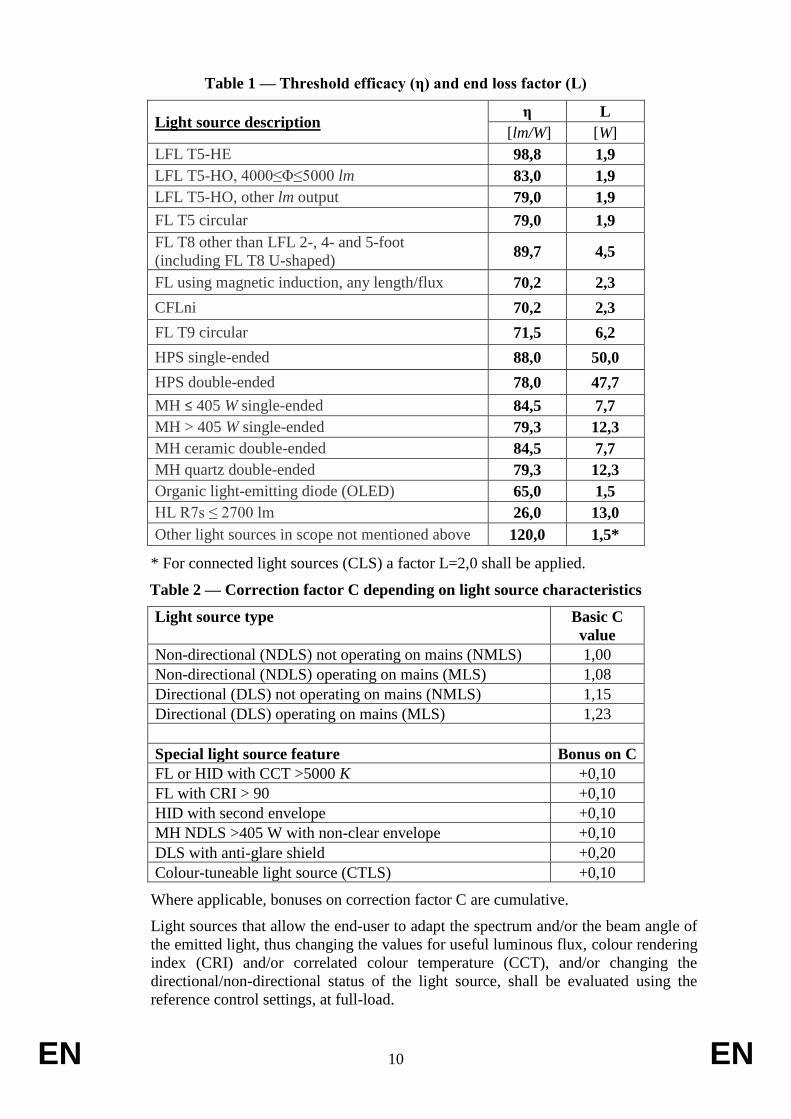
Table 1 — Threshold efficacy (η) and end loss factor (L)
Light source description η L
[lm/W] [W]
LFL T5-HE 98,8 1,9
LFL T5-HO, 4000≤Φ≤5000 lm 83,0 1,9
LFL T5-HO, other lm output 79,0 1,9
FL T5 circular 79,0 1,9
FL T8 other than LFL 2-, 4- and 5-foot
(including FL T8 U-shaped) 89,7 4,5
FL using magnetic induction, any length/flux 70,2 2,3
CFLni 70,2 2,3
FL T9 circular 71,5 6,2
HPS single-ended 88,0 50,0
HPS double-ended 78,0 47,7
MH ≤ 405 W single-ended 84,5 7,7
MH > 405 W single-ended 79,3 12,3
MH ceramic double-ended 84,5 7,7
MH quartz double-ended 79,3 12,3
Organic light-emitting diode (OLED) 65,0 1,5
HL R7s ≤ 2700 lm 26,0 13,0
Other light sources in scope not mentioned above 120,0 1,5*
* For connected light sources (CLS) a factor L=2,0 shall be applied.
Table 2 — Correction factor C depending on light source characteristics
Light source type Basic C
value
Non-directional (NDLS) not operating on mains (NMLS) 1,00
Non-directional (NDLS) operating on mains (MLS) 1,08
Directional (DLS) not operating on mains (NMLS) 1,15
Directional (DLS) operating on mains (MLS) 1,23
Special light source feature Bonus on C
FL or HID with CCT >5000 K +0,10
FL with CRI > 90 +0,10
HID with second envelope +0,10
MH NDLS >405 W with non-clear envelope +0,10
DLS with anti-glare shield +0,20
Colour-tuneable light source (CTLS) +0,10
Where applicable, bonuses on correction factor C are cumulative.
Light sources that allow the end-user to adapt the spectrum and/or the beam angle of
the emitted light, thus changing the values for useful luminous flux, colour rendering
index (CRI) and/or correlated colour temperature (CCT), and/or changing the
directional/non-directional status of the light source, shall be evaluated using the
reference control settings, at full-load.
EN 11 EN
The standby power Psb of a light source shall not exceed 0,5 W.
The networked standby power Pnet of a connected light source shall not exceed
0,5 W.
The allowable values for Psb and Pnet shall not be added together.
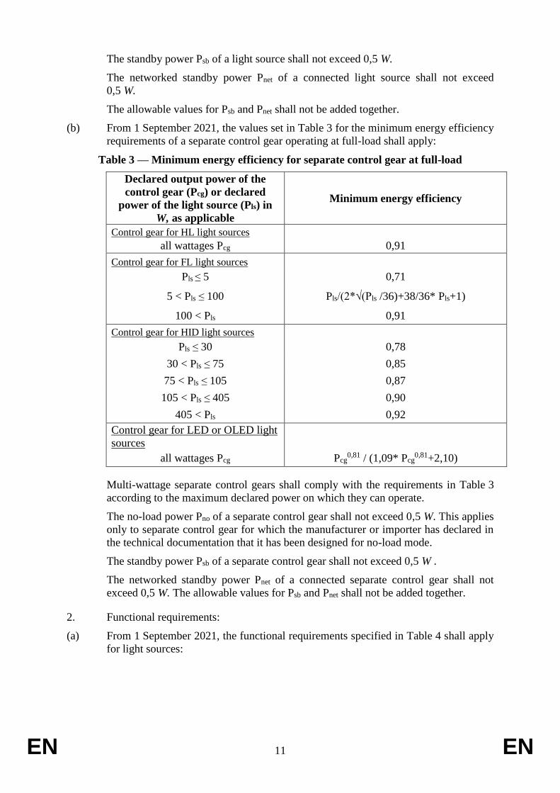
(b) From 1 September 2021, the values set in Table 3 for the minimum energy efficiency
requirements of a separate control gear operating at full-load shall apply:
Table 3 — Minimum energy efficiency for separate control gear at full-load
Declared output power of the
control gear (Pcg) or declared
power of the light source (Pls) in
W, as applicable
Minimum energy efficiency
Control gear for HL light sources
all wattages Pcg 0,91
Control gear for FL light sources
Pls ≤ 5 0,71
5 < Pls ≤ 100 Pls/(2*√(Pls /36)+38/36* Pls+1)
100 < Pls 0,91
Control gear for HID light sources
Pls ≤ 30 0,78
30 < Pls ≤ 75 0,85
75 < Pls ≤ 105 0,87
105 < Pls ≤ 405 0,90
405 < Pls 0,92
Control gear for LED or OLED light
sources
all wattages Pcg Pcg0,81 / (1,09* Pcg
0,81+2,10)
Multi-wattage separate control gears shall comply with the requirements in Table 3
according to the maximum declared power on which they can operate.
The no-load power Pno of a separate control gear shall not exceed 0,5 W. This applies
only to separate control gear for which the manufacturer or importer has declared in
the technical documentation that it has been designed for no-load mode.
The standby power Psb of a separate control gear shall not exceed 0,5 W .
The networked standby power Pnet of a connected separate control gear shall not
exceed 0,5 W. The allowable values for Psb and Pnet shall not be added together.
2. Functional requirements:
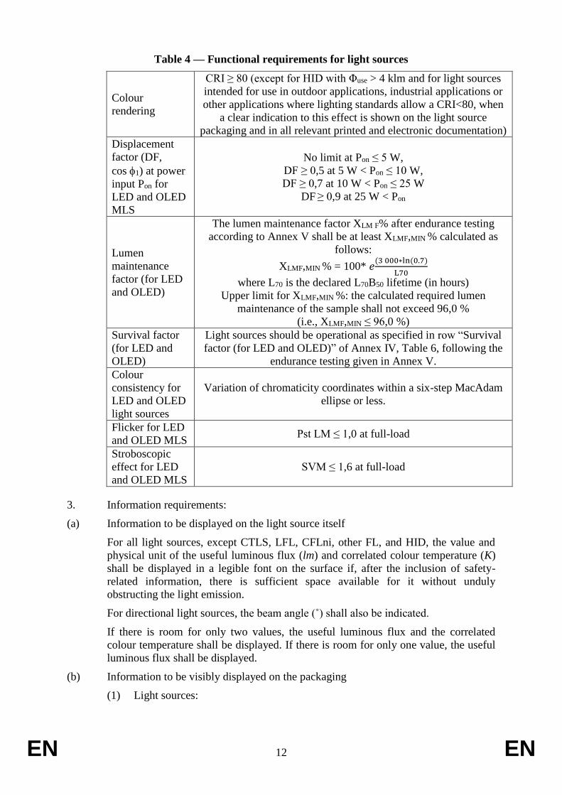
(a) From 1 September 2021, the functional requirements specified in Table 4 shall apply
for light sources:
EN 12 EN
Table 4 — Functional requirements for light sources
Colour
rendering
CRI ≥ 80 (except for HID with Φuse > 4 klm and for light sources
intended for use in outdoor applications, industrial applications or
other applications where lighting standards allow a CRI<80, when
a clear indication to this effect is shown on the light source
packaging and in all relevant printed and electronic documentation)
Displacement
factor (DF,
cos 1) at power
input Pon for
LED and OLED
MLS
No limit at Pon ≤ 5 W,
DF ≥ 0,5 at 5 W < Pon ≤ 10 W,
DF ≥ 0,7 at 10 W < Pon ≤ 25 W
DF ≥ 0,9 at 25 W < Pon
Lumen
maintenance
factor (for LED
and OLED)
The lumen maintenance factor XLM F% after endurance testing
according to Annex V shall be at least XLMF,MIN % calculated as
follows:
XLMF,MIN % = 100* 𝑒(3 000∗ln (0.7)
L70
where L70 is the declared L70B50 lifetime (in hours)
Upper limit for XLMF,MIN %: the calculated required lumen
maintenance of the sample shall not exceed 96,0 %
(i.e., XLMF,MIN ≤ 96,0 %)
Survival factor
(for LED and
OLED)
Light sources should be operational as specified in row “Survival
factor (for LED and OLED)” of Annex IV, Table 6, following the
endurance testing given in Annex V.
Colour
consistency for
LED and OLED
light sources
Variation of chromaticity coordinates within a six-step MacAdam
ellipse or less.
Flicker for LED
and OLED MLS Pst LM ≤ 1,0 at full-load
Stroboscopic
effect for LED
and OLED MLS
SVM ≤ 1,6 at full-load
3. Information requirements:
(a) Information to be displayed on the light source itself
For all light sources, except CTLS, LFL, CFLni, other FL, and HID, the value and
physical unit of the useful luminous flux (lm) and correlated colour temperature (K)
shall be displayed in a legible font on the surface if, after the inclusion of safety-
related information, there is sufficient space available for it without unduly
obstructing the light emission.
For directional light sources, the beam angle (˚) shall also be indicated.
If there is room for only two values, the useful luminous flux and the correlated
colour temperature shall be displayed. If there is room for only one value, the useful
luminous flux shall be displayed.
(b) Information to be visibly displayed on the packaging
(1) Light sources:
EN 13 EN
Light sources within the scope of this Regulation are within the scope of
Regulation (EU) [OP, please insert here references of the accompanying
energy labelling regulation] supplementing Regulation (EU) 2017/1369 with
regard to energy labelling for light sources. As concerns the information to be
visibly displayed on the packaging of light sources, manufacturers and
importers shall apply the requirements set out in Annex V of Regulation (EU)
[OP, please insert here references of the accompanying energy labelling
regulation].
(2) Separate control gears:
If a separate control gear is placed on the market as a stand-alone product and
not as a part of a containing product, in a packaging containing information to
be visibly displayed to potential buyers, prior to their purchase, the following
information shall be clearly and prominently displayed on the packaging:
(a) the maximum output power of the control gear (for HL, LED and OLED)
or the power of the light source for which the control gear is intended
(for FL and HID);
(b) the type of light source(s) for which it is intended;
(c) the efficiency in full-load, expressed in percentage;
(d) the no-load power (Pno), expressed in W and rounded to the second
decimal, or the indication that the gear is not intended to operate in no-
load mode. If the value is zero, it may be omitted from the packaging but
shall nonetheless be declared in the technical documentation and on
websites;
(e) the standby power (Psb), expressed in W and rounded to the second
decimal. If the value is zero, it may be omitted from the packaging but
shall nonetheless be declared in the technical documentation and on
websites;
(f) the networked standby power (Pnet), expressed in W and rounded to the
second decimal. If the value is zero, it may be omitted from the
packaging but shall nonetheless be declared in the technical
documentation and on websites;
(g) a warning if the control gear is not suitable for dimming of light sources
or can be used only with specific types of dimmable light sources or
using specific wired or wireless dimming methods. In the latter cases,
detailed information on the conditions in which the control gear can be
used for dimming shall be provided on the manufacturer’s or importer’s
website;
(h) a QR-code redirecting to a website optimised for mobile devices, or the
internet address for a website, where full information on the control gear
can be found.
The information does not need to use the exact wording on the list above.
Alternatively, it may be displayed in the form of graphs, drawings or symbols.
(c) Information to be visibly displayed on a free-access website
(1) Light sources:
EN 14 EN
Light sources within the scope of this Regulation are within the scope of
Regulation (EU) [OP, please insert here references of the accompanying
energy labelling regulation] supplementing Regulation (EU) 2017/1369 with
regard to energy labelling for light sources. As concerns the information to be
visibly displayed on a free-access website, manufacturers and importers shall
apply the requirements set out in Annex V of Regulation (EU) [OP, please
insert here references of the accompanying energy labelling regulation] in
relation to the product database set out in Article 4 of Regulation (EU)
2017/1369.
(2) Separate control gears:
For any separate control gear that is placed on the market, the following
information shall be displayed on at least one free-access website, including a
website optimised for mobile devices:
(a) the information specified in point 3(b)(2), except 3(b)(2)(h);
(b) the outer dimensions in mm;
(c) the mass in grams of the control gear, without packaging, and without
lighting control parts and non-lighting parts, if any and if they can be
physically separated from the control gear;
(d) instructions on how to remove lighting control parts and non-lighting
parts, if any, or how to switch them off or minimise their power
consumption during control-gear testing;
(e) if the control gear can be used with dimmable light sources, a list of
minimum characteristics that the light sources should have to be fully
compatible with the control gear during dimming, and possibly a list of
compatible dimmable light sources;
(f) recommendations on how to dispose of it at the end of its life in line with
Directive 2012/19/EU2.
In accordance with point 3(b)(2)(h) of this Annex, the website optimised for
mobile devices shall be linked to a QR-code on the packaging of the separate
control gear.
The information does not need to use the exact wording in the list above.
Alternatively, it may be displayed in the form of graphs, drawings or symbols.
Information on separate control gears that are no longer in production or that
are not, or no longer, intended for sale in the European Union should be clearly
marked as such and/or moved to a separate section of the website.
(d) Technical documentation
(1) Light sources:
Light sources within the scope of this Regulation are within the scope of
Regulation (EU) [OP, please insert here references of the accompanying
energy labelling regulation] supplementing Regulation (EU) 2017/1369 with
regard to energy labelling for light sources. The technical documentation for
the purposes of conformity assessment pursuant to Article 5 of this Regulation
shall include the information in the order and as set out in Annex VI of
2 OJ L 197, 24.7.2012, p. 38.
EN 15 EN
Regulation (EU) [OP, please insert here references of the accompanying
energy labelling regulation]. For market surveillance purposes, the verification
procedure set out in Annex IV to this Regulation applies; manufacturers may
refer to the technical documentation uploaded to the product database which
contains the same information in accordance with Regulation (EU) [OP, please
insert here references of the accompanying energy labelling regulation].
(2) Separate control gears:
The information specified in point 3(c)(2) of this Annex shall also be contained
in the technical documentation file drawn up for the purposes of conformity
assessment pursuant to Article 8 of Directive 2009/125/EC.
(e) Information for products specified in Annex III, point 3
For the light sources and separate control gears specified in Annex III, point 3, the
intended purpose shall be stated on all forms of packaging, product information and
advertisement, together with an explicit indication that the light source or separate
control gear is not intended for use in other applications.
In particular for light sources indicated in Annex III, point 3(p), it shall be stated:
‘This light source is only for use by photo sensitive patients. Use of this light source
will lead to increased energy cost compared to an equivalent more energy efficient
product.’
EN 16 EN
ANNEX III
Exemptions
1. This Regulation shall not apply to light sources and separate control gears
specifically tested and approved to operate:
(a) in potentially explosive atmospheres, as defined in Directive 2014/34/EU of
the European Parliament and of the Council3;
(b) for emergency use, as set out in Directive 2014/35/EU of the European
Parliament and of the Council4;
(c) in radiological and nuclear medicine installations, as defined in Article 3 of
Directive 2009/71/EURATOM5;
(d) in or on military or civil defence establishments, equipment, ground vehicles,
marine equipment or aircraft, as set out in Member States’ regulations or in
documents issued by the European Defence Agency;
(e) in or on motor vehicles, their trailers and systems, interchangeable towed
equipment, components and separate technical units as set out in Regulation
(EC) No 661/2009 of the European Parliament and of the Council6, Regulation
(EU) No 167/2013 of the European Parliament and of the Council7 and
Regulation (EU) No 168/2013 of the European Parliament and of the Council8;
(f) in or on non-road mobile machinery as set out in Regulation (EU) 2016/1628
of the European Parliament and of the Council9;
(g) in or on civil aviation aircrafts, as set out in Commission Regulation (EU)
No 748/201210;
(h) in railway vehicle lighting, as set out in Directive 2008/57/EC of the European
Parliament and of the Council11;
(i) in marine equipment, as set out in Directive 2014/90/EU of the European
Parliament and of the Council12;
(j) in medical devices, as set out in Council Directive 93/42/EEC13 and in vitro
medical devices as set out in Directive 98/79/EC of the European Parliament
and of the Council14.
For the purpose of this point, ‘specifically tested and approved’ means that the light
source or separate control gear:
– has been specifically tested for the mentioned operating condition or
application, according to the European legislation mentioned or related
3 OJ L 96, 29.3.2014, p. 309-356. 4 OJ L 96, 29..3.2014, p. 357. 5 OJ L 172, 2.7.2009, p. 18-. 6 OJ L 200, 31.7.2009, p. 1-24. 7 OJ L60, 2.3.2013, p. 1-51. 8 OJ L60, 2.3.2013, p. 52. 9 OJ L252, 16.9.2016, p. 53-117. 10 OJ L 224, 21.8.2012, p. 1-85. 11 OJ L 191, 18.7.2008, p. 1–45 12 OJ L 257, 28.8.2014, p. 146-185. 13 OJ L 169, 12.7.1993, p. 1. 14 OJ L331, 7.12.1998, p. 1.
EN 17 EN
implementing measures, or relevant European or international standards, or, in
the absence of these, according to relevant Member States legislation; and
– is accompanied by evidence, in the form of a certificate, a type approval mark,
a test report or other documentation, that the product has been specifically
approved for the mentioned operating condition or application; and
– is placed on the market specifically for the mentioned operating condition or
application, as evidenced at least by the technical documentation, information
on the packaging and any advertising or marketing materials.
2. In addition, this Regulation shall not apply to:
(a) double-capped fluorescent T5 light sources with power P ≤ 13 W;
(b) electronic displays (e.g. televisions, computer monitors, notebooks, tablets,
mobile phones, e-readers, game consoles), including but not limited to displays
within the scope of Regulation (EU) [OP, please insert here references of the
new regulation on ecodesign requirements for electronic displays and TVs],
Commission Regulation (EU) No 617/201315, Commission Decision (EU)
2015/140216, Commission Regulation (EC) No 642/200917, Commission
Decision (EU) 2016/175618, Commission Communication COM(2015) 17819;
(c) light sources in range hoods within the scope of Commission Delegated
Regulation (EU) No 65/2014;
(d) light sources and separate control gears in battery-operated products, including
but not limited to e.g. torches, mobile phones with an integrated torch light,
toys including light sources, desk lamps operating only on batteries, armband
lamps for cyclists, solar-powered garden lamps;
(e) light sources and separate control gears on bicycles and other non-motorised
vehicles.
3. Any light source or separate control gear within the scope of this Regulation shall be
exempt from the requirements of this Regulation, with the exception of the
information requirements set out in Annex II, point 3.e, if they are specifically
designed and marketed for their intended use in at least one of the following
applications:
(a) signalling (including, but not limited to, road-, railway-, marine- or air traffic-
signalling, traffic control or airfield lamps);
(b) image capture and image projection (including, but not limited to,
photocopying, printing (directly or in pre-processing), lithography, film and
video projection, holography);
(c) light sources with specific effective ultraviolet power >2 mW/klm and intended
for use in applications requiring high UV-content;
(d) light sources with a peak radiation around 253,7 nm and intended for
germicidal use (destruction of DNA);
15 OJ L 175, 27.6.2013, p. 13. 16 OJ L 217, 18.8.2015, p. 9 (office equipment, computers). 17 OJ L 191, 23.7.2009, p. 42 (televisions). 18 OJ L 268, 1.10.2016, p. 90 (office equipment, displays). 19 COM(2015) 178 final, 22.4.2015 (related to self-regulatory initiative regarding game consoles).
EN 18 EN
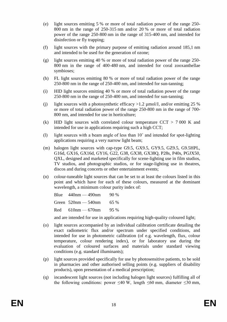
(e) light sources emitting 5 % or more of total radiation power of the range 250-
800 nm in the range of 250-315 nm and/or 20 % or more of total radiation
power of the range 250-800 nm in the range of 315-400 nm, and intended for
disinfection or fly trapping;
(f) light sources with the primary purpose of emitting radiation around 185,1 nm
and intended to be used for the generation of ozone;
(g) light sources emitting 40 % or more of total radiation power of the range 250-
800 nm in the range of 400-480 nm, and intended for coral zooxanthellae
symbioses;
(h) FL light sources emitting 80 % or more of total radiation power of the range
250-800 nm in the range of 250-400 nm, and intended for sun-tanning;
(i) HID light sources emitting 40 % or more of total radiation power of the range
250-800 nm in the range of 250-400 nm, and intended for sun-tanning;
(j) light sources with a photosynthetic efficacy >1.2 µmol/J, and/or emitting 25 %
or more of total radiation power of the range 250-800 nm in the range of 700-
800 nm, and intended for use in horticulture;
(k) HID light sources with correlated colour temperature CCT > 7 000 K and
intended for use in applications requiring such a high CCT;
(l) light sources with a beam angle of less than 10˚ and intended for spot-lighting
applications requiring a very narrow light beam;
(m) halogen light sources with cap-type G9.5, GX9.5, GY9.5, GZ9.5, G9.5HPL,
G16d, GX16, GX16d, GY16, G22, G38, GX38, GX38Q, P28s, P40s, PGJX50,
QXL, designed and marketed specifically for scene-lighting use in film studios,
TV studios, and photographic studios, or for stage-lighting use in theatres,
discos and during concerts or other entertainment events;
(n) colour-tuneable light sources that can be set to at least the colours listed in this
point and which have for each of these colours, measured at the dominant
wavelength, a minimum colour purity index of:
Blue 440nm — 490nm 90 %
Green 520nm — 540nm 65 %
Red 610nm — 670nm 95 %
and are intended for use in applications requiring high-quality coloured light;
(o) light sources accompanied by an individual calibration certificate detailing the
exact radiometric flux and/or spectrum under specified conditions, and
intended for use in photometric calibration (of e.g. wavelength, flux, colour
temperature, colour rendering index), or for laboratory use during the
evaluation of coloured surfaces and materials under standard viewing
conditions (e.g. standard illuminants);
(p) light sources provided specifically for use by photosensitive patients, to be sold
in pharmacies and other authorised selling points (e.g. suppliers of disability
products), upon presentation of a medical prescription;
(q) incandescent light sources (not including halogen light sources) fulfilling all of
the following conditions: power ≤40 W, length ≤60 mm, diameter ≤30 mm,
EN 19 EN
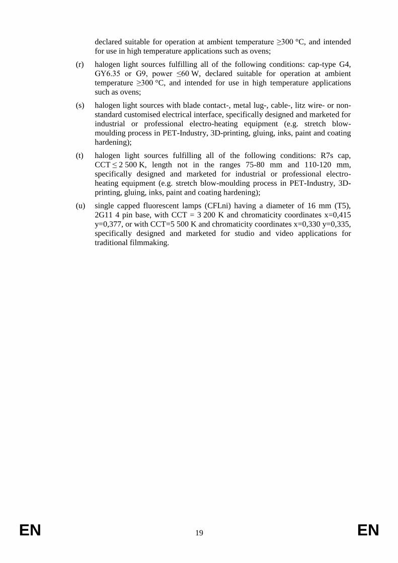
declared suitable for operation at ambient temperature ≥300 °C, and intended
for use in high temperature applications such as ovens;
(r) halogen light sources fulfilling all of the following conditions: cap-type G4,
GY6.35 or G9, power ≤60 W, declared suitable for operation at ambient
temperature ≥300 °C, and intended for use in high temperature applications
such as ovens;
(s) halogen light sources with blade contact-, metal lug-, cable-, litz wire- or non-
standard customised electrical interface, specifically designed and marketed for
industrial or professional electro-heating equipment (e.g. stretch blow-
moulding process in PET-Industry, 3D-printing, gluing, inks, paint and coating
hardening);
(t) halogen light sources fulfilling all of the following conditions: R7s cap,
CCT ≤ 2 500 K, length not in the ranges 75-80 mm and 110-120 mm,
specifically designed and marketed for industrial or professional electro-
heating equipment (e.g. stretch blow-moulding process in PET-Industry, 3D-
printing, gluing, inks, paint and coating hardening);
(u) single capped fluorescent lamps (CFLni) having a diameter of 16 mm (T5),
2G11 4 pin base, with CCT = 3 200 K and chromaticity coordinates x=0,415
y=0,377, or with CCT=5 500 K and chromaticity coordinates x=0,330 y=0,335,
specifically designed and marketed for studio and video applications for
traditional filmmaking.
EN 20 EN
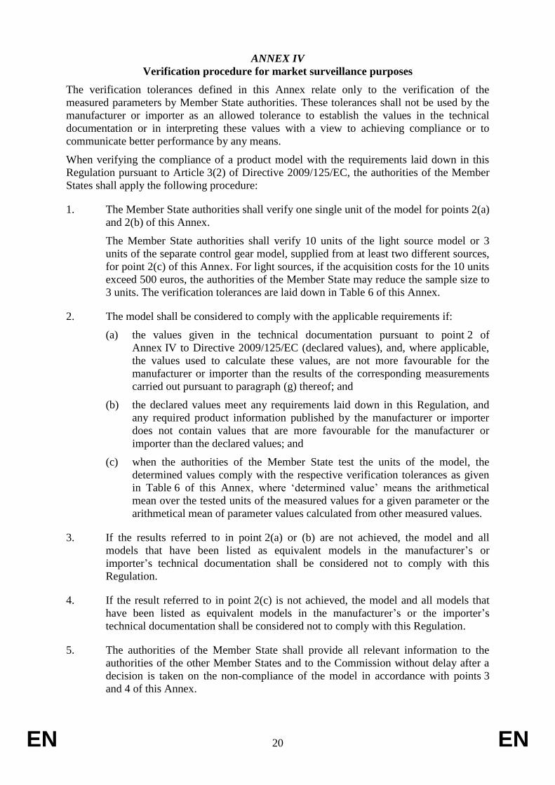
ANNEX IV
Verification procedure for market surveillance purposes
The verification tolerances defined in this Annex relate only to the verification of the
measured parameters by Member State authorities. These tolerances shall not be used by the
manufacturer or importer as an allowed tolerance to establish the values in the technical
documentation or in interpreting these values with a view to achieving compliance or to
communicate better performance by any means.
When verifying the compliance of a product model with the requirements laid down in this
Regulation pursuant to Article 3(2) of Directive 2009/125/EC, the authorities of the Member
States shall apply the following procedure:
1. The Member State authorities shall verify one single unit of the model for points 2(a)
and 2(b) of this Annex.
The Member State authorities shall verify 10 units of the light source model or 3
units of the separate control gear model, supplied from at least two different sources,
for point 2(c) of this Annex. For light sources, if the acquisition costs for the 10 units
exceed 500 euros, the authorities of the Member State may reduce the sample size to
3 units. The verification tolerances are laid down in Table 6 of this Annex.
2. The model shall be considered to comply with the applicable requirements if:
(a) the values given in the technical documentation pursuant to point 2 of
Annex IV to Directive 2009/125/EC (declared values), and, where applicable,
the values used to calculate these values, are not more favourable for the
manufacturer or importer than the results of the corresponding measurements
carried out pursuant to paragraph (g) thereof; and
(b) the declared values meet any requirements laid down in this Regulation, and
any required product information published by the manufacturer or importer
does not contain values that are more favourable for the manufacturer or
importer than the declared values; and
(c) when the authorities of the Member State test the units of the model, the
determined values comply with the respective verification tolerances as given
in Table 6 of this Annex, where ‘determined value’ means the arithmetical
mean over the tested units of the measured values for a given parameter or the
arithmetical mean of parameter values calculated from other measured values.
3. If the results referred to in point 2(a) or (b) are not achieved, the model and all
models that have been listed as equivalent models in the manufacturer’s or
importer’s technical documentation shall be considered not to comply with this
Regulation.
4. If the result referred to in point 2(c) is not achieved, the model and all models that
have been listed as equivalent models in the manufacturer’s or the importer’s
technical documentation shall be considered not to comply with this Regulation.
5. The authorities of the Member State shall provide all relevant information to the
authorities of the other Member States and to the Commission without delay after a
decision is taken on the non-compliance of the model in accordance with points 3
and 4 of this Annex.
EN 21 EN
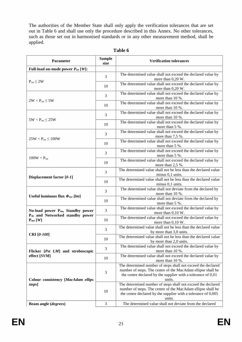
The authorities of the Member State shall only apply the verification tolerances that are set
out in Table 6 and shall use only the procedure described in this Annex. No other tolerances,
such as those set out in harmonised standards or in any other measurement method, shall be
applied.
Table 6
Parameter Sample
size Verification tolerances
Full-load on-mode power Pon [W]:
Pon ≤ 2W
3 The determined value shall not exceed the declared value by
more than 0,20 W.
10 The determined value shall not exceed the declared value by
more than 0,20 W.
2W < Pon ≤ 5W
3 The determined value shall not exceed the declared value by
more than 10 %.
10 The determined value shall not exceed the declared value by
more than 10 %.
5W < Pon ≤ 25W
3 The determined value shall not exceed the declared value by
more than 10 %.
10 The determined value shall not exceed the declared value by
more than 5 %.
25W < Pon ≤ 100W
3 The determined value shall not exceed the declared value by
more than 7,5 %.
10 The determined value shall not exceed the declared value by
more than 5 %.
100W < Pon
3 The determined value shall not exceed the declared value by
more than 5 %.
10 The determined value shall not exceed the declared value by
more than 2,5 %.
Displacement factor [0-1]
3 The determined value shall not be less than the declared value
minus 0,1 units.
10 The determined value shall not be less than the declared value
minus 0,1 units.
Useful luminous flux Φuse [lm]
3 The determined value shall not deviate from the declared by
more than 10 %.
10 The determined value shall not deviate from the declared by
more than 5 %.
No-load power Pno, Standby power
Psb and Networked standby power
Pnet [W]
3 The determined value shall not exceed the declared value by
more than 0,10 W.
10 The determined value shall not exceed the declared value by
more than 0,10 W.
CRI [0-100]
3 The determined value shall not be less than the declared value
by more than 3,0 units.
10 The determined value shall not be less than the declared value
by more than 2,0 units.
Flicker [Pst LM] and stroboscopic
effect [SVM]
3 The determined value shall not exceed the declared value by
more than 10 %.
10 The determined value shall not exceed the declared value by
more than 10 %.
Colour consistency [MacAdam ellips
steps]
3
The determined number of steps shall not exceed the declared
number of steps. The centre of the MacAdam ellipse shall be
the centre declared by the supplier with a tolerance of 0,01
units.
10
The determined number of steps shall not exceed the declared
number of steps. The centre of the MacAdam ellipse shall be
the centre declared by the supplier with a tolerance of 0,005
units.
Beam angle (degrees) 3 The determined value shall not deviate from the declared
EN 22 EN
value by more than 25 %.
10 The determined value shall not deviate from the declared
value by more than 25 %.
Control gear efficiency [0-1]
3 The determined value shall not be less than the declared value
minus 0,05 units.
10 The determined value shall not be less than the declared value
minus 0,025 units.
Efficacy [lm/W]
3 The determined value (quotient) shall not be less than the
declared value minus 10 %.
10 The determined value (quotient) shall not be less than the
declared value minus 5 %.
L70B50 lifetime (for LED and OLED)
3 The determined value shall not be less than the declared value
minus 20 %.
10 The determined value shall not be less than the declared value
minus 10 %.
Lumen maintenance factor (for LED
and OLED)
3 The determined XLMF% of the sample following the test in
Annex V of this Regulation shall not be less than XLMF,
MIN%20. 10
Survival factor
(for LED and OLED)
3 All 3 light sources of the test sample must be operational after
completing the test in Annex V of this Regulation.
10 At least 9 light sources of the test sample must be operational
after completing the test in Annex V of this Regulation.
Colour purity index [%]
3 The determined value shall not be less than the declared value
minus 10 %.
10 The determined value shall not be less than the declared value
minus 5 %.
Correlated colour temperature [K]
3 The determined value shall not deviate from the declared
value by more than 10 %.
10 The determined value shall not deviate from the declared
value by more than 5 %.
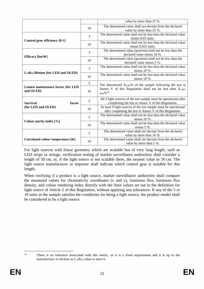
For light sources with linear geometry which are scalable but of very long length, such as
LED strips or strings, verification testing of market surveillance authorities shall consider a
length of 50 cm, or, if the light source is not scalable there, the nearest value to 50 cm. The
light source manufacturer or importer shall indicate which control gear is suitable for this
length.
When verifying if a product is a light source, market surveillance authorities shall compare
the measured values for chromaticity coordinates (x and y), luminous flux, luminous flux
density, and colour rendering index directly with the limit values set out in the definition for
light source of Article 2 of this Regulation, without applying any tolerances. If any of the 3 or
10 units in the sample satisfies the conditions for being a light source, the product model shall
be considered to be a light source.
20 There is no tolerance associated with this metric, as it is a fixed requirement and it is up to the
manufacturer to declare an L70B50 value to meet it.
EN 23 EN
ANNEX V
Functionality after endurance testing
Models of LED- and OLED- light sources shall undergo endurance testing to verify their
lumen maintenance and survival factor. This endurance testing consists of the test method
outlined below. The authorities of a Member State shall test 10 units of the model for this test.
However, if the acquisition costs for 10 units exceed EUR 500, the authorities of a Member
State have the option to reduce the sample size to 3 units.
The endurance test for LED and OLED light sources shall be conducted as follows:
(a) Ambient conditions and test setup:
(i) The switching cycles are to be conducted in a room with an ambient
temperature of 25 ±10 °C and an average air velocity of less than 0,2 m/s.
(ii) The switching cycles on the sample shall be conducted in free air in a vertical
base-up position. However, if a manufacturer or importer has declared the light
source suitable for use in a specific orientation only, then the sample shall be
mounted in that orientation.
(iii) The applied voltage during the switching cycles shall have a tolerance within
2 %. The total harmonic content of the supply voltage shall not exceed 3 %.
Standards provide guidance on the supply voltage source.
(b) Provisional endurance test method:
(i) Initial flux measurement: measure the luminous flux of the light source prior to
starting the endurance test switching cycle.
(ii) Switching cycles: operate the light source for 1 200 cycles of repeated,
continuous switching cycles without interruption. One complete switching
cycle consists of 150 minutes of the light source switched ON at full power
followed by 30 minutes of the light source switched OFF. The hours of
operation recorded (i.e., 3 000 hours) include only the periods of the switching
cycle when the light source was switched ON, i.e. the total test time is 3 600
hours.
(iii) Final flux measurement: at the end of the 1 200 switching cycles, note if any
lamps have failed (see ‘Survival factor’ in Annex IV, Table 6 of this
Regulation) and measure the luminous flux of the light sources that have not
failed.
(iv) For each of the units in the sample which have not failed, divide the measured
final flux by the measured initial flux. Average the resulting values over all the
units that did not fail to compute the determined value for the lumen
maintenance factor XLMF %.
EN 24 EN
ANNEX VI
Benchmarks
For the environmental aspects that were considered significant and are quantifiable, the best
available technology on the market, at the time of entry into force of this Regulation, is
indicated below.
The best available technology on the market for light sources in terms of their efficacy based
on useful luminous flux was identified as follows:
– Non-directional light sources: 120-140 lm/W
– Mains voltage directional light sources: 90-100 lm/W
– Extra low voltage directional light sources: 85- 95 lm/W
– Linear light sources (tubes): 140-160 lm/W
The best available technology on the market for separate control gears have an energy
efficiency of 95 %.
Features required in certain applications, e.g. a high colour rendering, might prevent products
offering those features from achieving these benchmarks.
The best available technology on the market for light sources and separate control gears do
not have any mercury content.