Embed Size (px)
Citation preview
O-Ring Prüflabor Richter GmbH Kleinbottwarer Str. 1 71723 Großbottwar
Telefon 07148 / 16602-0 Fax 07148 / 16602-299 [email protected] www.o-ring-prueflabor.de
Geschäftsführer: Dipl.-Ing. Bernhard Richter Ust-ID-Nr. DE 277600966 Steuer-Nr. 71342/02407 FA LB
Sitz der Gesellschaft: Großbottwar Amtsgericht Stuttgart HRB 737482
Volksbank Ludwigsburg IBAN DE96 6049 0150 0820 5810 03 SWIFT GENODES1LBG
1
EXPERT KNOWLEDGE
TEST PROCEDURES
OF ELASTOMER COMPONENTS
An offer of
TESTING CONSULTING DEVELOPING
Source: www.o-ring-prueflabor.de
Information as of 10/2014
Tensile Test– Test Engineering Basics and
Recommendations for Practical Application
Authors:
Dipl.-Ing. (FH) Ulrich Blobner,
Dipl.-Ing. Bernhard Richter
Test standards used: DIN 53504 (Edition 10-2009), ISO 37 (Edition 12-2011), VDA 675 205
(Edition 12-1992), ASTM D412 06a (Reapproved 2013), ASTM D1414 94 (Reapproved 2008)
1. Definition of the Tensile Test
During the tensile test, standardized test specimens (in most cases dumbbell specimens) are
clamped in a tensile testing machine and stretched at a constant feed rate until they tear.
During this process, the course of the required force and elongation is recorded and a tensile
elongation diagram is generated. Important individual parameters are tensile strength at break
and elongation at break. It is also a helpful instrument for making comparative conclusions
between non-preloaded, new and aged materials.
O-Ring Prüflabor Richter GmbH Kleinbottwarer Str. 1 71723 Großbottwar
Telefon 07148 / 16602-0 Fax 07148 / 16602-299 [email protected] www.o-ring-prueflabor.de
Geschäftsführer: Dipl.-Ing. Bernhard Richter Ust-ID-Nr. DE 277600966 Steuer-Nr. 71342/02407 FA LB
Sitz der Gesellschaft: Großbottwar Amtsgericht Stuttgart HRB 737482
Volksbank Ludwigsburg IBAN DE96 6049 0150 0820 5810 03 SWIFT GENODES1LBG
2
2. Purpose of Tensile Testing - Practical Benefits
The following sections will demonstrate why tensile testing is a very conclusive test method
that can be used to obtain very different, varied and helpful information about materials and
finished parts.
2.1 Statements About the Mechanical Load-Bearing Capacity (Elongation, Strength)
The results from the tensile test are in many cases of less interest to the designer at first glance
since elastomers are rarely subjected to permanent tensile strain. However, it should not be
forgotten that large expansions can occur during the assembly process. This can result in
expansions of more than 100%. Moreover, a high elongation at break in the case of highly
compressed seals results in greater resistance to stress cracking. It prevents the gasket from
bursting inside due to the high deformation. However, high tensile strength also has application
benefits in terms of improved abrasion resistance and greater resistance to gap extrusion.1
If compounds with higher strength values exist within the same polymer family, this often
indicates better and higher quality compound components. However, it must be checked in
detail whether this higher strength is actually required for the specific application. If there are
several similar elastomer compounds to choose from for an application, the tensile strength
should rarely be the decisive selection criterion. Other characteristic values are much more
important, such as compression set or aging in hot air or mediums, which are also determined
with the aid of tensile tests.
When drawing up material specifications, care should be taken not to demand unnecessarily
high tensile strengths and elongation at break. These could perhaps be achieved by an
experienced compounder and high-quality compound components, but mostly at the expense
of other more important material parameters and process-ability or price.
2.2 Statements About the Formulation and Processing Quality of a Material
According to DICK2, the tensile test provides the quality assurance engineer with information
as to whether the compound has been thoroughly mixed and dispersed, whether impurities
due to foreign particles such as dirt or paper are present, whether the material has been over-
or under-cross-linked, or whether porosities are present. If, for example, carbon black particles
are not sufficiently dispersed, carbon black agglomerates may occur, which can cause
premature tearing of the test specimens. Porosities usually arise during tempering due to
volatile components in the mixture. Due to all these possible errors, it is common in the rubber
industry to carry out a batch test (tensile strength and elongation at break) during series
production.
It is not always easy to find out whether problems are due to poor compound quality or poor
processing quality (e.g. injection molding or pressing). Sometimes the tensile test is not
sufficient and other test and analysis methods have to be considered.
Finally, it is important for the practitioner to know that laboratory compounds normally have
1 This only applies in combination with other material properties such as hardness, good tear resistance and
compression set. 2 DICK, John S.: Rubber Technology – Compounding and Testing for Performance, München, 2001, S.49
O-Ring Prüflabor Richter GmbH Kleinbottwarer Str. 1 71723 Großbottwar
Telefon 07148 / 16602-0 Fax 07148 / 16602-299 [email protected] www.o-ring-prueflabor.de
Geschäftsführer: Dipl.-Ing. Bernhard Richter Ust-ID-Nr. DE 277600966 Steuer-Nr. 71342/02407 FA LB
Sitz der Gesellschaft: Großbottwar Amtsgericht Stuttgart HRB 737482
Volksbank Ludwigsburg IBAN DE96 6049 0150 0820 5810 03 SWIFT GENODES1LBG
3
better tensile strengths than production-scale compounds because the former are more
thoroughly dispersed. This means that the tensile strengths measured on finished parts may
be lower than the values measured on test plates for material release, because test plate
mixtures are often produced in the laboratory.
2.3 Lifetime and Mechanical and Chemical Resistance of Materials / Load Limits
(Aging)
In order to obtain information about the service life of materials, aged test rods are compared
with production-fresh ones. Aging takes place either by air or specific test mediums (e.g. oils,
fuels, hot water, etc.) at elevated temperatures. Of primary interest here are the percentage
changes in the test parameters tensile strength and elongation at break, which provide
information about the network structure. The percentage changes indicate the extent to which
the three-dimensional network is damaged.
Long test durations and correspondingly adapted test temperatures can also be used to
simulate lifetime loads.
These tests are carried out both within the framework of material development and during release testing in accordance with the specifications of seal users (e.g. OEMs in the automotive sector). With the help of the tensile test, the compound developer obtains information about cross-
linking systems and interactions of various compound components, e.g. active carbon black or
fillers. Many compounders usually work with the aid of statistical design of experiments (DoE).
The results from the tensile test are usually a very important parameter here.
2.4 Determination of Material Characteristics for Numerical Calculations
Computer simulations are also playing an increasingly important role in the elastomer industry.
In contrast to many other materials, however, the calculation of elastomers is a very complex
field, since the thermoviscoelasticity of rubber materials and other important properties of a
compound strongly depend on the respective compound and application temperature and
cannot be easily calculated and described. As can quickly be seen from the force/elongation
curves, the properties of elastomers are not linear, which requires more complicated
calculation algorithms.
Moreover, in contrast to the plastics industry3, there is a much larger number of different
elastomer compounds, so that in very few cases formulation-specific material databases can
be used for the calculation.
In order to obtain the material model of a mixture, a comprehensive determination of the
respective material characteristics is necessary, depending on the problem at hand. The tensile
test (partly also with temperature chamber) is one of several important test methods.4 5
3 In the plastics industry, for example, the material data of the most important types of plastics are available on
the Internet in the CAMPUS database: http://www.campusplastics.com/campus. Some of these data can also be used for calculations.
4 http://www.axelproducts.com/pages/hyperelastic.html (Webseite abgerufen am 09.07.2014) 5 http://www.axelproducts.com/downloads/TestingForHyperelastic.pdf (Webseite abgerufen am
09.07.2014)
O-Ring Prüflabor Richter GmbH Kleinbottwarer Str. 1 71723 Großbottwar
Telefon 07148 / 16602-0 Fax 07148 / 16602-299 [email protected] www.o-ring-prueflabor.de
Geschäftsführer: Dipl.-Ing. Bernhard Richter Ust-ID-Nr. DE 277600966 Steuer-Nr. 71342/02407 FA LB
Sitz der Gesellschaft: Großbottwar Amtsgericht Stuttgart HRB 737482
Volksbank Ludwigsburg IBAN DE96 6049 0150 0820 5810 03 SWIFT GENODES1LBG
4
Structural-mechanical simulations (simulation of material aging6 and lifetime estimations)7 as
well as calculations can then be carried out, which are of great use in the development8 and
optimization of elastomer components.9
2.5 Statements on Polymer-Filler Interactions
In the non-linear stress / strain curve, which often has an alternating point, the effect of the
reinforcing fillers is reflected among other aspects. While in the first more strongly rising part
of the curve, polymer chains primarily are stretched. In the flattening part, the partial
detachment of the polymer from the filler can be seen. Further details can be found in section
5.2.6 of this article.
3. Important Test Standards for Tensile Tests: Description of the Test
Procedure and Important Characteristic Values
The ISO 37 and DIN 5350410 standards most frequently used in our everyday laboratory work
define testing on standard test specimens.
3.1 Standardized Specimens
Dumbbell-shaped test specimens, so-called dumbbell bars, are most frequently used. These
are usually punched out of vulcanized elastomer test plates. The following table gives an
overview of the most important key data of these test bars.
6 vgl. ACHENBACH, Manfred: Modellierung der Alterung von Gummi in: STREIT, Gerhard (Hrsg.): Elastomere
Dichtungssysteme, Expert Verlag, Renningen, 2011, S.291ff. 7 vgl. ACHENBACH, Manfred: Modell zur Thermoviskoelastizität von Elastomeren: Modelle zur Beschreibung
des thermo-mechanischen Eigenschaftsprofils von elastomeren Dichtungsmaterialien und ihre Verwendung in Finite Elemente Simulationen von Dichtungssystemen in: STREIT, Gerhard (Hrsg.): Elastomere Dichtungssysteme, Expert Verlag, Renningen, 2011, S.213ff.
8 vgl. ACHENBACH, Manfred und BOSCHET, René: Auslegungen von Dichtungen mit der FEM in: STREIT,
Gerhard (Hrsg.): Elastomere Dichtungssysteme, Expert Verlag, Renningen, 2011, S.321ff. 9 STOMMEL, Markus und STOJEK, Marcus und KORTE, Wolfgang: FEM zur Berechnung von Kunststoff- und
Elastomerbauteilen, Carl Hanser Verlag, München, 2011 10 The content of DIN 53504 (edition 10-2009) was largely adapted to ISO 37 from 2005. This technical article will
mainly deal with ISO 37, with cross-references to special features and deviations in DIN 53504.
O-Ring Prüflabor Richter GmbH Kleinbottwarer Str. 1 71723 Großbottwar
Telefon 07148 / 16602-0 Fax 07148 / 16602-299 [email protected] www.o-ring-prueflabor.de
Geschäftsführer: Dipl.-Ing. Bernhard Richter Ust-ID-Nr. DE 277600966 Steuer-Nr. 71342/02407 FA LB
Sitz der Gesellschaft: Großbottwar Amtsgericht Stuttgart HRB 737482
Volksbank Ludwigsburg IBAN DE96 6049 0150 0820 5810 03 SWIFT GENODES1LBG
5
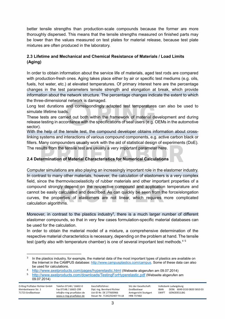
Fig. 1: Sketch of a dumbbell bar: the
designation of the distances is taken from ISO
37.11
Dimensions [mm] Dumbbell Bar
Type 1 Type 1A Type 2 Type 3 Type 4
Total Length A 115 100 75 50 35
Head Width B 25 ± 1 25 ± 1 12.5 ± 1 8,5 ± 0.5 6 ± 0.5
Bridge Length C 33 ± 2 21 ± 1 25 ± 1 16 ± 1 12 ± 0.5
Bridge Width D 6.2 ± 0.2 5 ± 0.1 4 ± 0.1 4 ± 0.1 2 ± 0.1
Dumbbell Thickness 2 ± 0.2 2 ± 0.2 2 ± 0.2 2 ± 0.2 1 ± 0.1
Initial Measuring
Length
25 ± 0.5
20 ± 0.5 20 ± 0.5 10 ± 0.5 10 ± 0.5
Tab.1: Dimensions of the ISO 37 dumbbell bars12
The test rods in DIN 53504 are almost identical to those in ISO 37 except for minimal
differences. However, there are different descriptions of the test rods:
ISO 37 DIN 53504 Deviations (Except Tolerance Ranges):
Type 1 S1
Type 1A S1A Outer transition half radius: ISO 37(25mm), DIN 53504 (20mm) Initial measuring length: ISO 37(20mm), DIN 53504 (25mm)
Type 2 S2
Type 3 S3A
Type 4 S3
Table 2: Comparison of the different designations of the corresponding shoulder bars
in ISO 37 and DIN 53504 with indication of significant differences in dimensions
11 ISO 37 (issue 12-2011), P.7 12 The data have been taken from ISO 37 (edition 12-2011), p.5f.
O-Ring Prüflabor Richter GmbH Kleinbottwarer Str. 1 71723 Großbottwar
Telefon 07148 / 16602-0 Fax 07148 / 16602-299 [email protected] www.o-ring-prueflabor.de
Geschäftsführer: Dipl.-Ing. Bernhard Richter Ust-ID-Nr. DE 277600966 Steuer-Nr. 71342/02407 FA LB
Sitz der Gesellschaft: Großbottwar Amtsgericht Stuttgart HRB 737482
Volksbank Ludwigsburg IBAN DE96 6049 0150 0820 5810 03 SWIFT GENODES1LBG
6
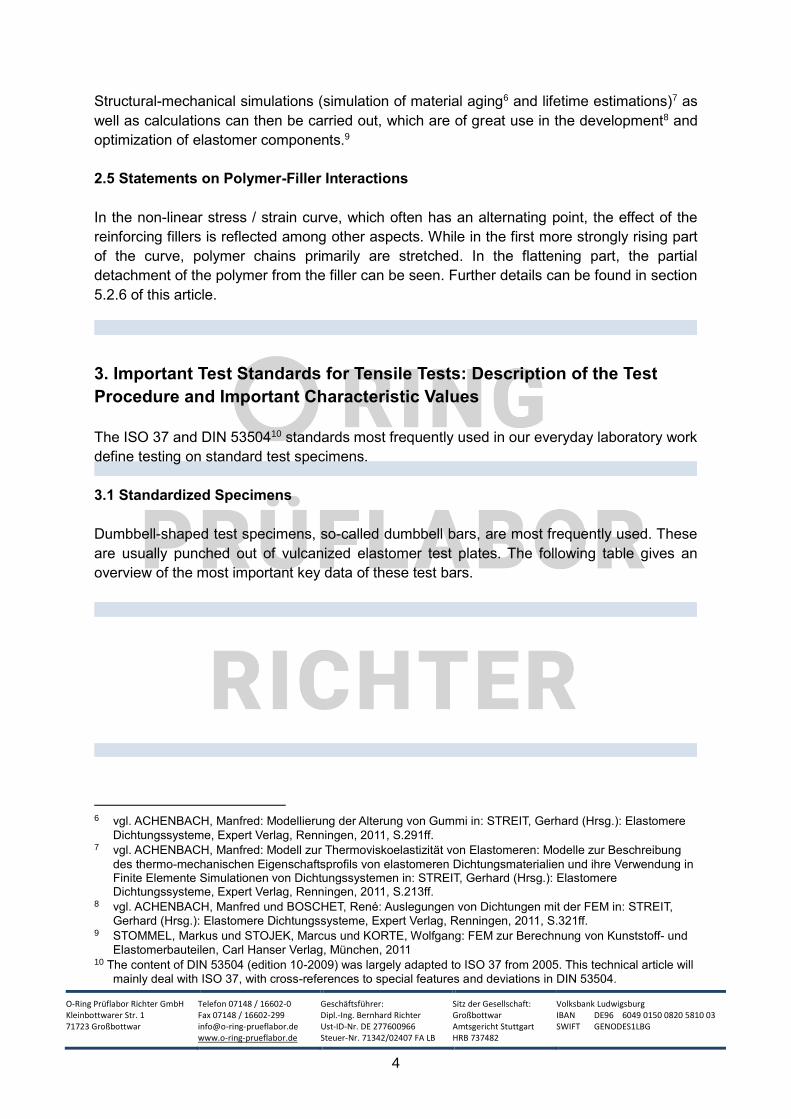
ISO 37 also permits two different rings with a rectangular cross-section for tensile testing. DIN
53504 also prescribes two rings, but both standards have only one standard ring in common,
as the following table shows:
Dimensions [mm] Ring
ISO 37 Not Standardized Type A Type B
DIN 53504 R1 R2 not standardized
Outer Diameter d3 52.6 44.6 10
Inside Diameter d4 44.6 36.6 8
Width b 4 4 1
Thickness a 4 (or 6.3 in DIN) 4 (or 6.3 in DIN) 1
Tab. 3: Standardized rectangular rings for tensile testing (see Fig. 2 for an explanation of the indices)
Fig. 2: Representation of a standardized
rectangular ring from DIN 5350413
The explanation of the calculation of the initial gauge length and the mean circumference for
the stress value would be too much at this point. Reference is made here to the notes in the
two standards.
The production of test specimens requires a high degree of care and experience. Scoring and
notching during classical punching can lead to a significant deterioration of the results. This is
discussed in more detail in sub-section 5.1.
DIN 53504 also provides information on the testing of O-rings. ASTM International even has
its own standard (ASTM D1414), which only deals with the testing of O-rings. A separate article
under the heading, "Tensile test" deals with the special features of tensile tests on O-rings.
13 Picture used from DIN 53504 (Edition 10-2009), p.8
O-Ring Prüflabor Richter GmbH Kleinbottwarer Str. 1 71723 Großbottwar
Telefon 07148 / 16602-0 Fax 07148 / 16602-299 [email protected] www.o-ring-prueflabor.de
Geschäftsführer: Dipl.-Ing. Bernhard Richter Ust-ID-Nr. DE 277600966 Steuer-Nr. 71342/02407 FA LB
Sitz der Gesellschaft: Großbottwar Amtsgericht Stuttgart HRB 737482
Volksbank Ludwigsburg IBAN DE96 6049 0150 0820 5810 03 SWIFT GENODES1LBG
7
3.2 Meaning and Differences of Dumbbell Bars vs. Standard Rings
While in the 1960s the ring - introduced many decades earlier by MARTENS14 at the
State Materials Testing Office in Berlin - became established as the most widely used
test specimen15. Today, it has largely been replaced by the dumbbell bar. The ring had
the advantage that continuous scanning of the change in length of the strain area was
no longer necessary. This scanning is no longer a problem with today's testing
machines and their long-stroke extensometers. Occasionally, the rings are still used in
compound production for batch release in batch production. However, the dumbbell
bar has become completely accepted for compound releases for the following reasons:
At present, classic punching tools are increasingly being replaced by punching knives
(see sub-section 5.1 Preparation of Test Specimens). In test laboratories, which still work
with classic punching tools, the large negative influence of a possible non-ideal cutting
edge on the test results is less with a 2 mm thick shoulder bar than with a 4 mm thick
rectangular ring.
Due to the larger cross-section to be torn, rings usually provide worse values than test
rods. This effect is explained in more detail in sub-section 5.4 Influence of the Specimen
Cross-Section / Volume.
Dumbbell bars can be used to examine the influence of the rolling direction16 of the test
plate by punching half of the test bars to be examined out of the test plate at a 90° angle.
That is because the properties of a test plate are usually not ideally isotropic. This effect
becomes particularly clear with the test of the tear resistance.
Fewer test plates are required as their surface can be used more efficiently with dumbbell
bars than with rings.
3.3 Test Speeds
As test speed (actually speed of strain) in ISO 37
200 mm/min (for bar test specimens type 3 and 4 and small ring type B), and
500 mm/min (for Type 1, 1A and 2 rod test specimens and Type A large ring) are required.
DIN 53504 requires a feed rate of 200 mm/min for the dumbbell bars S2, S3 and S3A and a
feed rate of 500 mm/min for the larger bars S1 and S1A. The two rings R1 and R2 should be
tested at 500 mm/min.
14 Adolf Martens (1850-1914) was at the end of the 19th century one of the most important and outstanding
materials researchers and examiners in the German Empire. He was particularly outstanding in the field of materials testing of metals. His name was immortalized in the name of an iron-carbon structure, namely "martensite". For many years he was head of the Royal Materials Testing Office in Dahlem near Berlin. Source of information: http://www.amf.bam.de/de/adolf_martens/index.htm (access to website on: 11.04.2014)
15 vgl. ECKER, R.: Mechanische-technologische Prüfung von Kautschuk und Gummi in: BOSTRÖM, S. (Hrsg.).:
Kautschuk-Handbuch , Band 5, Stuttgart, 1962, S. 102 16 vgl. BROWN, Roger: Physical Testing of Rubber, New York, 42006, S. 134
O-Ring Prüflabor Richter GmbH Kleinbottwarer Str. 1 71723 Großbottwar
Telefon 07148 / 16602-0 Fax 07148 / 16602-299 [email protected] www.o-ring-prueflabor.de
Geschäftsführer: Dipl.-Ing. Bernhard Richter Ust-ID-Nr. DE 277600966 Steuer-Nr. 71342/02407 FA LB
Sitz der Gesellschaft: Großbottwar Amtsgericht Stuttgart HRB 737482
Volksbank Ludwigsburg IBAN DE96 6049 0150 0820 5810 03 SWIFT GENODES1LBG
8
3.4. Useful Information from ASTM D412
In the related test standard ASTM D 412 ("Standard Test Methods for Vulcanized Rubber and
Thermoplastic Elastomers - Tension"), there are six standard test rods. Their dimensions differ
from those in ISO 37. In addition, there are four different test rings, two of which correspond to
the dimensions of the ISO 37 rings. The most frequently required test speed is 500 mm/min.
In many other respects there is a high technical comparability to ISO 37.
3.5 Important Parameters17 from the Tensile Test and Their Significance for Practical
Application
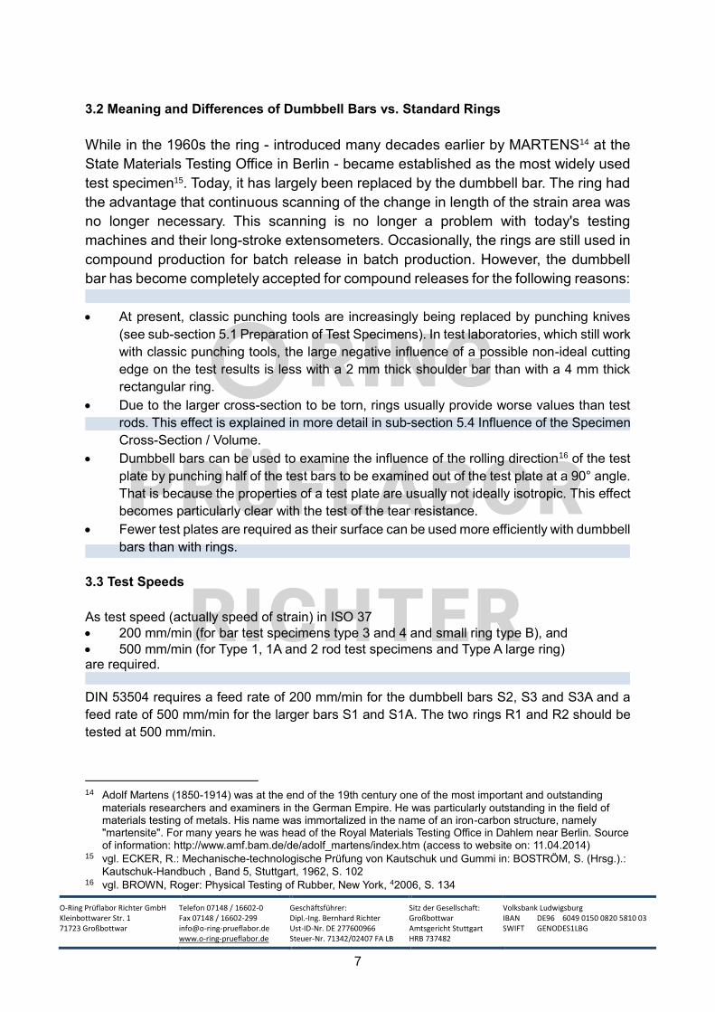
The tensile strength at break σR is the force at the moment of tearing FR of the specimen,
relative to the initial cross section A0. It is given in N/mm² or MPa with the following ratio:
1N/mm² = 1 MPa.
A related material parameter is the tensile strength σmax. This is the quotient of the maximum
force Fmax and the initial cross section A0. For most elastomers, however, the maximum force
is the same as the force at the moment of tearing.
It should be noted that the terms tensile strength at break and tensile strength are often used
synonymously because "in the case of elastomers (...) the force FR occurring during tearing is
generally also the maximum force Fmax when the tensile test is carried out at room temperature
or at temperatures above room temperature".18 This mistaken equation of the two characteristic
values can lead to problems if FR and Fmax are not identical.
Fig. 3: Classical tensile elongation curve
of an elastomer: The maximum force
Fmax (=TS) is equal to the force FR (TSb)
occurring during tearing.19
17 The terms and abbreviations are taken from DIN 53504, p.5f. 18 Translated from DIN 53504 (Ausgabe 10-2009), S.6 19 The diagram is based on ISO 37 (edition 12-2011), p.3. The designations and abbreviations of ISO 37 were
retained for standardization purposes.
O-Ring Prüflabor Richter GmbH Kleinbottwarer Str. 1 71723 Großbottwar
Telefon 07148 / 16602-0 Fax 07148 / 16602-299 [email protected] www.o-ring-prueflabor.de
Geschäftsführer: Dipl.-Ing. Bernhard Richter Ust-ID-Nr. DE 277600966 Steuer-Nr. 71342/02407 FA LB
Sitz der Gesellschaft: Großbottwar Amtsgericht Stuttgart HRB 737482
Volksbank Ludwigsburg IBAN DE96 6049 0150 0820 5810 03 SWIFT GENODES1LBG
9
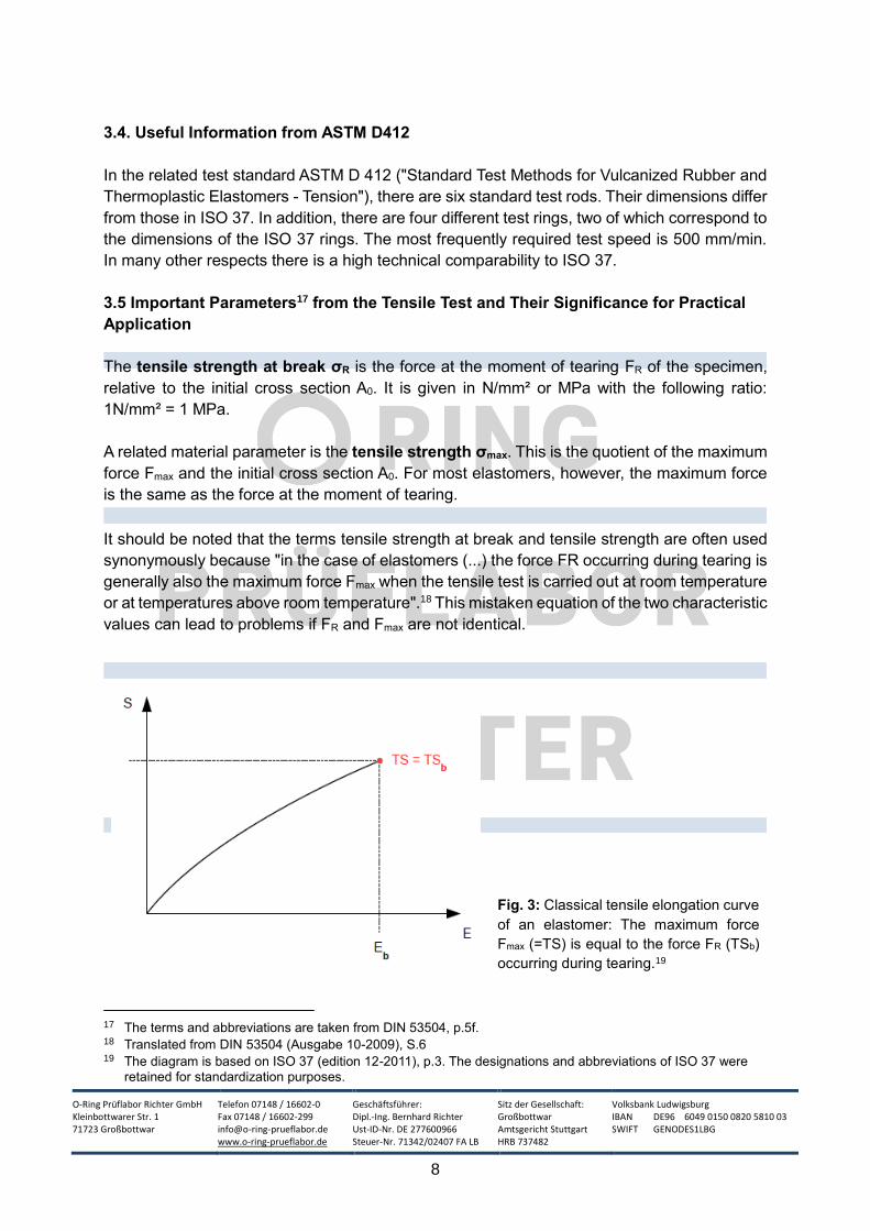
Legend:
E = elongation [%]
Eb = elongation at break [%]
Ey = elongation at yield
S = stress
Sy = stress at yield
TS = tensile strength [N/mm²]
TSb = tensile strength at
break [N/mm²]
Y = yield point
Fig.4: Rare special case in the tensile testing of elastomers: The maximum force Fmax (=TS) differs
from the force Fmax (Tsb) occurring during tearing. There is a maximum (=Y) which is reached
significantly before the tear.20
The following table provides an overview and classification of the usual strength ranges of
elastomers:
Tensile Strength Range Classification
0 to 5 N/mm² Elastomer with low strength
5 to 10 N/mm² Elastomer of medium strength
10 to 15 N/mm² Elastomer with high strength
Larger than 15 N/mm² Elastomer with very high strength
Tab. 4: Tensile strength ranges of elastomers
Before the tensile test, a specific measuring length or initial length L0 is determined. In order
to obtain the elongation at break εR, the difference between the total length LR at the moment
of breaking and the measured or initial length L0 is calculated. This difference is then divided
by the measuring length or initial length L0. Since the elongation at break is usually expressed
as a percentage, the result must be multiplied by 100.
With elastomers, the elongation during the tensile test results in an extreme reduction of the
original cross-section. If the stress were calculated with the cross-section at the moment of
tearing, the result would sometimes be up to ten times as large21. This has to do with the fact
that due to the high elongation and crystallization effects the strength increases temporarily.
20 Ebd., S.3 21 vgl. HOUWINK, R.: Grundriss der Technologie der synthetischen Hochmolekularen, Leipzig, 1952, S. 85
O-Ring Prüflabor Richter GmbH Kleinbottwarer Str. 1 71723 Großbottwar
Telefon 07148 / 16602-0 Fax 07148 / 16602-299 [email protected] www.o-ring-prueflabor.de
Geschäftsführer: Dipl.-Ing. Bernhard Richter Ust-ID-Nr. DE 277600966 Steuer-Nr. 71342/02407 FA LB
Sitz der Gesellschaft: Großbottwar Amtsgericht Stuttgart HRB 737482
Volksbank Ludwigsburg IBAN DE96 6049 0150 0820 5810 03 SWIFT GENODES1LBG
10
The technical literature also presents approximate formulas for calculating the true tensile
strength at break. SPÄTH derives such a formula on the assumption of "uniform elongation
over the entire test length and a constant test volume"22:
A * L0 = A' * LR
A = Initial cross section of the test specimen in the area to be torn
A' = Cross section at the moment of tearing
L0 = Initial length of the measuring section
LR = Total length at the moment of tearing (LR = L0 + ΔL) ΔL = Increase in length L during tearing
A' = A * (1/(1+ε))
ε = ((LR-L0) / L0) = ΔL/L0 = relative elongation L0 / LR = (1/(1+ε))
σw = F/A' = (F/A) * (1 + ε) = σR * (1 + ε)
F = force at the moment of tearing
σw = "true" tensile strength at break
σR = measured tensile strength at break
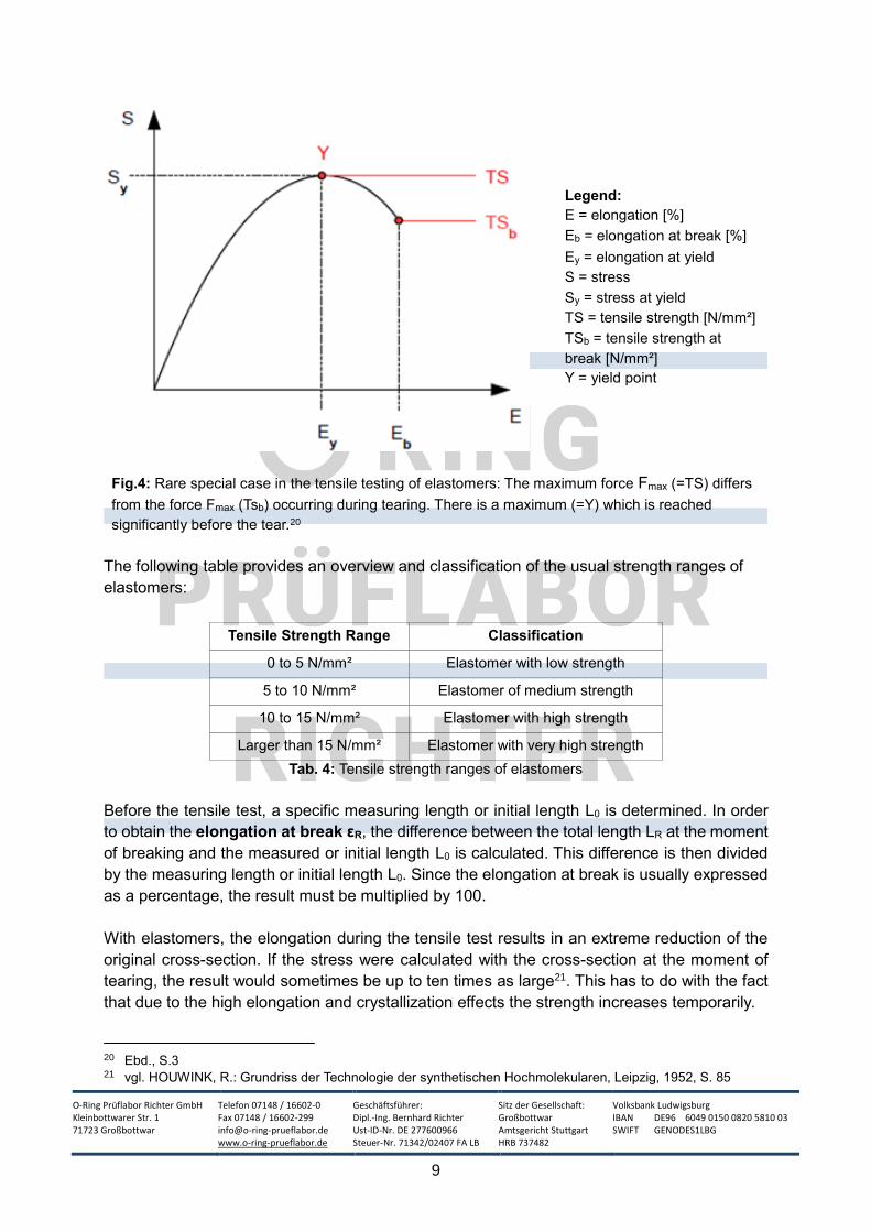
Fig. 5: Tensile test rod clamped in a tensile testing
machine before the start of loading. The
extensometers do not yet touch the measuring area23
between the shoulders.
22 SPÄTH, Wilhelm: Beiträge zur Technologie der Hochpolymeren: Gummi und Kunststoffe, A.W. Gentner
Verlag, Stuttgart, 1956, S.109f. 23 The initial gauge length is standardized (see Table1) and is always slightly shorter than the length of bar C
O-Ring Prüflabor Richter GmbH Kleinbottwarer Str. 1 71723 Großbottwar
Telefon 07148 / 16602-0 Fax 07148 / 16602-299 [email protected] www.o-ring-prueflabor.de
Geschäftsführer: Dipl.-Ing. Bernhard Richter Ust-ID-Nr. DE 277600966 Steuer-Nr. 71342/02407 FA LB
Sitz der Gesellschaft: Großbottwar Amtsgericht Stuttgart HRB 737482
Volksbank Ludwigsburg IBAN DE96 6049 0150 0820 5810 03 SWIFT GENODES1LBG
11
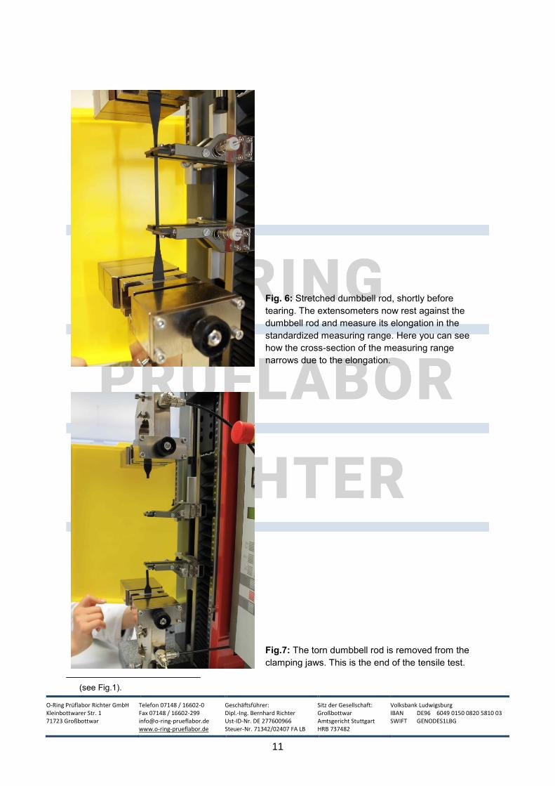
Fig. 6: Stretched dumbbell rod, shortly before
tearing. The extensometers now rest against the
dumbbell rod and measure its elongation in the
standardized measuring range. Here you can see
how the cross-section of the measuring range
narrows due to the elongation.
Fig.7: The torn dumbbell rod is removed from the
clamping jaws. This is the end of the tensile test.
(see Fig.1).
O-Ring Prüflabor Richter GmbH Kleinbottwarer Str. 1 71723 Großbottwar
Telefon 07148 / 16602-0 Fax 07148 / 16602-299 [email protected] www.o-ring-prueflabor.de
Geschäftsführer: Dipl.-Ing. Bernhard Richter Ust-ID-Nr. DE 277600966 Steuer-Nr. 71342/02407 FA LB
Sitz der Gesellschaft: Großbottwar Amtsgericht Stuttgart HRB 737482
Volksbank Ludwigsburg IBAN DE96 6049 0150 0820 5810 03 SWIFT GENODES1LBG
12
In the tensile testing of metals, there is a relatively large and pronounced range in which the
Hooke's law applies, meaning that there is a direct proportionality between stress and strain.
The application limits of metals are usually within this range. The designer therefore can use
precise moduli of elasticity.
With elastomers, on the other hand, there is only a very small area in which Hook's law applies.
Rubber materials are almost always used in a range for which no single modulus of elasticity
can be specified. ECKER refers here to the "differential modulus of elasticity E' ". In tensile
tests, it is often common to specify the stress values at, e.g. 100% or 200% elongation.
According to DIN 53504, the "Stress value σi is the quotient of the tensile force Fi present
when a certain elongation is reached and the initial cross-section A0." 24
Sometimes the earlier common term "module value" (e.g. M100 for the stress value at 100%
elongation) can still be found. For the reasons given above, however, this is factually incorrect
and should therefore be avoided.
4. Technical Requirements for Tensile Testing Machines and Their
Software for Testing Elastomers
While it was still difficult in the 1960s to obtain tensile testing machines with a deformation
speed that could be varied in the range of powers of ten, which had a relatively inertia-free
force and travel display25 and which enabled simple and accurate evaluation of the results, it
is no longer a problem today.
The following special equipment is helpful when testing elastomers:
When testing elastomers, high travels at relatively low forces (<500N) are often to be
expected, as some materials have elongations at break of 700% or more. Therefore, tensile
testing machines with long traverses are required and the extensometers must also be able to
travel the long distances. Maximum measuring ranges up to 750mm are sufficient in our daily
testing routine.
The extensometers must be so robust that they will not be damaged by a possible
knockback when the specimen tears. On the other hand, they must only be applied to
the specimen with a such low force that sensitive specimens do not tear at the contact
point. In addition, the linear guide should work as frictionless as possible, since
generally low forces are used when testing elastomers.26 The resolutions (3μm27 or
better) and accuracies (0.1mm or better) currently available are sufficient for testing in
the elastomer range.
24 DIN 53504 (Edition 10-2009), p.6 25 vgl. ECKER, R.: Mechanische-technologische Prüfung von Kautschuk und Gummi in: BOSTRÖM, S. (Hrsg.).:
Kautschuk-Handbuch , Band 5, Stuttgart, 1962, S. 102 26 vgl. KÖNIG, Klaus: Präzision unter Spannung in KGK, 05/2013, Artikel abgerufen am 19.06.2014:
http://www.kgk-rubberpoint.de/texte/anzeigen/4344/Praezision-unter-Spannung 27 vgl. www.en.wikipedia.org/wiki/Extensometer (Zugriff auf Webseite am 04.08.2014)
O-Ring Prüflabor Richter GmbH Kleinbottwarer Str. 1 71723 Großbottwar
Telefon 07148 / 16602-0 Fax 07148 / 16602-299 [email protected] www.o-ring-prueflabor.de
Geschäftsführer: Dipl.-Ing. Bernhard Richter Ust-ID-Nr. DE 277600966 Steuer-Nr. 71342/02407 FA LB
Sitz der Gesellschaft: Großbottwar Amtsgericht Stuttgart HRB 737482
Volksbank Ludwigsburg IBAN DE96 6049 0150 0820 5810 03 SWIFT GENODES1LBG
13
It is also possible to measure the change in length with the help of a laser or a video recording.
For this method, marking points must be attached to the test rods, which can sometimes lead
to problems (e.g. with test rods stored in oil or certain materials). If a laser is used, the laser
beam may be deflected by the pane of the temperature chamber during tests in temperature
chambers. This problem does not occur with the more modern video systems, which film the
strain, process it with a computer and evaluate it.28
In addition, R&D facilities sometimes require the initial stiffnesses, meaning initial pitches, of a
material. Since these are relatively small strain ranges, the 1/10mm accuracy mentioned above
is not sufficient. However, there are also technical solutions for these rare exceptions.
Special attention must also be paid to the selection of the specimen grips or clamping jaws. Due to the high deformability of elastomers, the specimen shrinks during the tensile test. This creates the danger that the specimen slips out of the clamping jaw. This problem is usually solved by the use of self-clamping fixtures. This type of grips, which are also called "wedge grips" by a well-known tensile testing machine manufacturer, have the following advantages:
They "are very well suited for shrinking specimens as they automatically retighten and
thereby compensate the decreasing specimen thickness.
The wedge grips are symmetrically closing. This automatically positions the specimen
in the tensile axis and no thickness adjustment is required.
Due to the large clamping length and good jaw guidance properties, the surface
pressure on the specimen can be kept low.
Due to their high temperature resistance and low overall height, they are very well
suited for use in temperature chambers"29
As an alternative, there are also pneumatically operated clamping jaws (pneumatic
specimen grips). They are suitable for clamp-sensitive materials, and the combination with
foot-switches makes operation much easier as the laboratory technician now has both hands
free during the clamping process. This type of clamping tool has the following advantages:
“The separation of tensile force and closing force ensures a constant clamping force
during the entire test sequence.
The contact pressure on the sample is reproducible [and controllable via the air
pressure].
A (...) constant force system protects the specimen from unwanted forces during the
clamping process.
Clamping-sensitive specimens can be held securely by adjusting the pneumatic
pressure and clamping breaks can be avoided."30
The surface of the clamping jaws or clamping jaw inserts is also important. It must have a
structure in which the shrinking elastomer specimen can get caught without causing
28 vgl. BROWN, Roger: Physical Testing of Rubber, New York, 42006, S. 144f. 29 Translated from http://www.zwick.de/de/produkte/probenhalter-pruefwerkzeuge/keil-
spannwerkzeuge.html (Zugriff auf Webseite am 19.06.2014) 30 http://www.zwick.de/de/produkte/probenhalter-pruefwerkzeuge/pneumatik-probenhalter-und-
steuereinheiten.html (Zugriff auf Webseite am 19.06.2014)
O-Ring Prüflabor Richter GmbH Kleinbottwarer Str. 1 71723 Großbottwar
Telefon 07148 / 16602-0 Fax 07148 / 16602-299 [email protected] www.o-ring-prueflabor.de
Geschäftsführer: Dipl.-Ing. Bernhard Richter Ust-ID-Nr. DE 277600966 Steuer-Nr. 71342/02407 FA LB
Sitz der Gesellschaft: Großbottwar Amtsgericht Stuttgart HRB 737482
Volksbank Ludwigsburg IBAN DE96 6049 0150 0820 5810 03 SWIFT GENODES1LBG
14
predetermined breaking points or cracks due to sharp edges. In some cases, elastomer-coated
clamping jaw inserts are also used.
Most tensile tests are performed at room temperature (23°C), but a temperature chamber can
be used to determine strength values at elevated or low temperatures. Interestingly, here is
the percentage drop or increase of the strength/elongation values due to the temperature
difference. These findings can be particularly important for seals that are subjected to high
temperatures and tensile stress during use. In most cases, the temperature chamber can be
approached from behind the tensile testing machine and can enclose the clamping jaws and
extensometers together with the specimen. Heating is usually carried out with an electric
heater, cooling with liquid nitrogen. For elastomers, a test range of -60°C to 250°C is sufficient.
In our daily testing practice, however, the use of a temperature chamber is irrelevant, even if
this would sometimes make sense from an application technology point of view.
After all, good software for evaluating the test results is important. In addition to intuitive and
largely self-explanatory operation, special attention must also be paid to interfaces for
transferring and converting the data into generally used formats. Due to today's possibilities of
EDP, many data sets are created even with simpler tensile tests, which are only of use if they
can be saved and retrieved easily and for the most part can be read out at least in their basic
data without special software.
The special features of the tensile test of O-rings, including the special accessories required,
are dealt with in a separate technical article.
5. Useful Information for the Interpretation and Evaluation of Test Results
from the Tensile Test
The tensile test can be used, among other aspects, to determine the optimum degree of
cross-linking of a material. On the other hand, it is also important to know which external
influencing factors can significantly change or even falsify test results from the tensile test.
Only with this background knowledge is it possible to test accurately and reproducibly and to
interpret the results sensibly for practical use.
5.1 Influences of Tensile Strength or Degree of Cross-Linking on Material Properties
Similar to the compression set, the tensile strength is also an indirect measure of the cross-
linking density of a material. The cross-linking density has an important influence on various
important properties of a seal. There is no specific cross-linking density at which all properties
achieve an optimum, but a compromise must be found for the respective application. This can
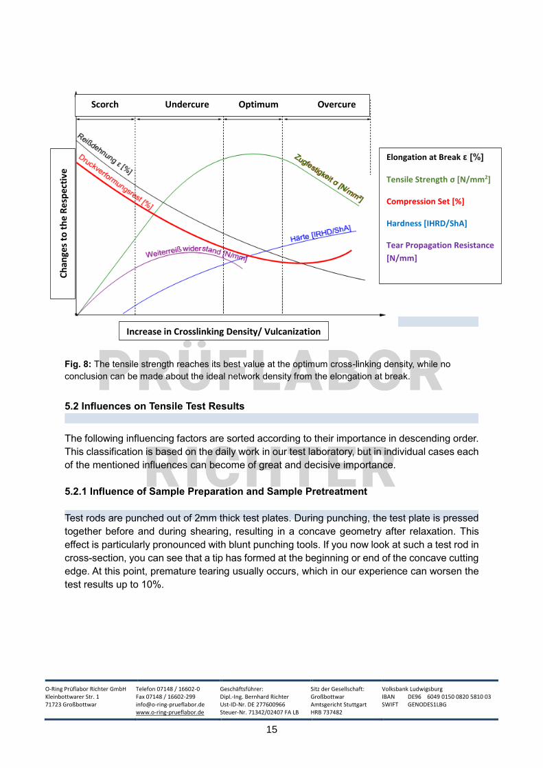
be seen from the following graph31 (Fig. 8):
31 This diagram was created and revised with the help of the following template from the technical literature:
MATSCHINSKI, Paul (Hrsg.): Roh- und Hilfsstoffe in der Gummiindustrie, VEB Deutscher Verlag für Grundstoffindustrie, Leipzig, 1968, S. 171
O-Ring Prüflabor Richter GmbH Kleinbottwarer Str. 1 71723 Großbottwar
Telefon 07148 / 16602-0 Fax 07148 / 16602-299 [email protected] www.o-ring-prueflabor.de
Geschäftsführer: Dipl.-Ing. Bernhard Richter Ust-ID-Nr. DE 277600966 Steuer-Nr. 71342/02407 FA LB
Sitz der Gesellschaft: Großbottwar Amtsgericht Stuttgart HRB 737482
Volksbank Ludwigsburg IBAN DE96 6049 0150 0820 5810 03 SWIFT GENODES1LBG
15
Fig. 8: The tensile strength reaches its best value at the optimum cross-linking density, while no
conclusion can be made about the ideal network density from the elongation at break.
5.2 Influences on Tensile Test Results
The following influencing factors are sorted according to their importance in descending order.
This classification is based on the daily work in our test laboratory, but in individual cases each
of the mentioned influences can become of great and decisive importance.
5.2.1 Influence of Sample Preparation and Sample Pretreatment
Test rods are punched out of 2mm thick test plates. During punching, the test plate is pressed
together before and during shearing, resulting in a concave geometry after relaxation. This
effect is particularly pronounced with blunt punching tools. If you now look at such a test rod in
cross-section, you can see that a tip has formed at the beginning or end of the concave cutting
edge. At this point, premature tearing usually occurs, which in our experience can worsen the
test results up to 10%.
Scorch Undercure Optimum Overcure
Ch
ange
s to
th
e R
esp
ecti
ve
Par
ame
ters
Increase in Crosslinking Density/ Vulcanization
Time
Elongation at Break ε [%]
Tensile Strength σ [N/mm2]
Compression Set [%]
Hardness [IHRD/ShA]
Tear Propagation Resistance
[N/mm]

O-Ring Prüflabor Richter GmbH Kleinbottwarer Str. 1 71723 Großbottwar
Telefon 07148 / 16602-0 Fax 07148 / 16602-299 [email protected] www.o-ring-prueflabor.de
Geschäftsführer: Dipl.-Ing. Bernhard Richter Ust-ID-Nr. DE 277600966 Steuer-Nr. 71342/02407 FA LB
Sitz der Gesellschaft: Großbottwar Amtsgericht Stuttgart HRB 737482
Volksbank Ludwigsburg IBAN DE96 6049 0150 0820 5810 03 SWIFT GENODES1LBG
16
Fig.9: Typical punching tool: The tool has a spring activated ejector for the
dumbbell rods.
Recently, punching knives have also been offered. These tools have thin interchangeable
blades, similar to a carpet knife. Due to the thin blade cross section, hardly any material is
displaced. The punching knives "can be changed without any problems, so there are no
downtimes and regrinding costs. Each punching knife has [also] an integrated ejector.“32 The
result is a test rod with an exact rectangular cross-section.
Fig. 10: Punching knife: The screws on the punching knife are necessary for
changing the blades. The tool also has a spring activated ejector for the
dumbbell rods.
We speak of punched test bars if they were produced with a classic punching tool and of cut test bars if they were produced with a punching knife. "Cut" here does not mean a pulling cut, as is done with a knife in the case of food, for example, nor is it a cutting with a circular rotating blade, but rather a "punched cutting".
32 Translated from http://www.hess-mbv.de/kcfinder/upload/files/Dumbbell%20Messer.pdf (Zugriff auf Webseite
am 28.05.2014)
O-Ring Prüflabor Richter GmbH Kleinbottwarer Str. 1 71723 Großbottwar
Telefon 07148 / 16602-0 Fax 07148 / 16602-299 [email protected] www.o-ring-prueflabor.de
Geschäftsführer: Dipl.-Ing. Bernhard Richter Ust-ID-Nr. DE 277600966 Steuer-Nr. 71342/02407 FA LB
Sitz der Gesellschaft: Großbottwar Amtsgericht Stuttgart HRB 737482
Volksbank Ludwigsburg IBAN DE96 6049 0150 0820 5810 03 SWIFT GENODES1LBG
17
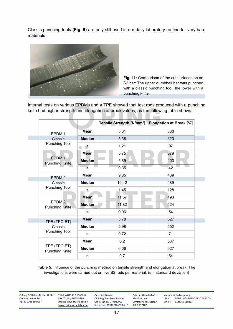
Classic punching tools (Fig. 9) are only still used in our daily laboratory routine for very hard
materials.
Fig. 11: Comparison of the cut surfaces on an
S2 bar: The upper dumbbell bar was punched
with a classic punching tool, the lower with a
punching knife.
Internal tests on various EPDMs and a TPE showed that test rods produced with a punching
knife had higher strength and elongation at break values, as the following table shows:
Tensile Strength [N/mm²] Elongation at Break [%]
EPDM 1
Classic Punching Tool
Mean 5.31 330
Median 5.38 323
s 1.21 97
EPDM 1
Punching Knife
Mean 5.75 379
Median 5.89 403
s 0.35 42
EPDM 2
Classic Punching Tool
Mean 9.85 439
Median 10.42 489
s 1.45 128
EPDM 2
Punching Knife
Mean 11.57 493
Median 11.82 524
s 0.96 54
TPE (TPC-ET)
Classic Punching Tool
Mean 5.78 527
Median 5.98 552
s 0.72 71
TPE (TPC-ET)
Punching Knife
Mean 6.2 537
Median 6.06 527
s 0.7 54
Table 5: Influence of the punching method on tensile strength and elongation at break. The
investigations were carried out on five S2 rods per material. (s = standard deviation)
O-Ring Prüflabor Richter GmbH Kleinbottwarer Str. 1 71723 Großbottwar
Telefon 07148 / 16602-0 Fax 07148 / 16602-299 [email protected] www.o-ring-prueflabor.de
Geschäftsführer: Dipl.-Ing. Bernhard Richter Ust-ID-Nr. DE 277600966 Steuer-Nr. 71342/02407 FA LB
Sitz der Gesellschaft: Großbottwar Amtsgericht Stuttgart HRB 737482
Volksbank Ludwigsburg IBAN DE96 6049 0150 0820 5810 03 SWIFT GENODES1LBG
18
5.2.2 Influence of Increased Temperature
At a certain deformation speed a strong internal heating takes place in the specimen. This is
referred to as the "Gough-Joule effect" in technical literature.33 Most tensile tests are
thermodynamically adiabatic and non-isothermal processes, since the heat generated cannot
be dissipated quickly enough due to the poor thermal conductivity of elastomers.34
However, the following section will not deal with these effects, but with the heating of the
specimen, the extensometers and the clamping jaws before the actual tensile test with the aid
of a temperature chamber.
In general, the tensile strength and elongation at break of elastomers decrease with increasing
temperature. At high temperatures, the physical load limits of an elastomeric material
decrease, which is why such tests are not only interesting due to aging effects, but also provide
indications of the real load limits of a material in real use, which usually takes place at elevated
temperatures. In the case of compounds with a high filler content, the temperature influence is
lower.
Depending on the elastomer base, there are compounds whose strength decreases
significantly more in heat than with other compounds. As described above, the strength
requirements in most applications are far from reaching the actual strength limits of the
compounds. However, most cracks begin at flaws, so that much lower forces or deformations
are sufficient to trigger a seal failure. By testing at elevated temperatures, it is now easier to
estimate how much this risk increases as the temperature rises.
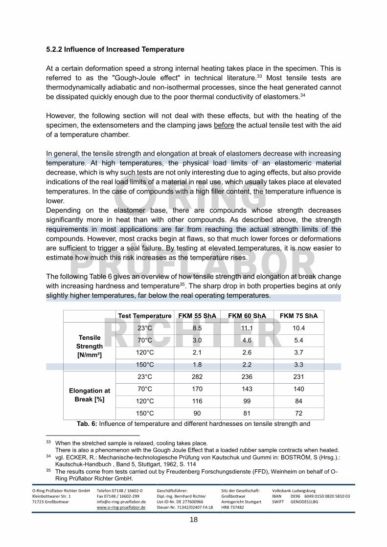
The following Table 6 gives an overview of how tensile strength and elongation at break change
with increasing hardness and temperature35. The sharp drop in both properties begins at only
slightly higher temperatures, far below the real operating temperatures.
Test Temperature FKM 55 ShA FKM 60 ShA FKM 75 ShA
Tensile
Strength
[N/mm²]
23°C 8.5 11.1 10.4
70°C 3.0 4.6 5.4
120°C 2.1 2.6 3.7
150°C 1.8 2.2 3.3
Elongation at
Break [%]
23°C 282 236 231
70°C 170 143 140
120°C 116 99 84
150°C 90 81 72
Tab. 6: Influence of temperature and different hardnesses on tensile strength and
33 When the stretched sample is relaxed, cooling takes place.
There is also a phenomenon with the Gough Joule Effect that a loaded rubber sample contracts when heated. 34 vgl. ECKER, R.: Mechanische-technologiesche Prüfung von Kautschuk und Gummi in: BOSTRÖM, S (Hrsg.).:
Kautschuk-Handbuch , Band 5, Stuttgart, 1962, S. 114 35 The results come from tests carried out by Freudenberg Forschungsdienste (FFD), Weinheim on behalf of O-
Ring Prüflabor Richter GmbH.
O-Ring Prüflabor Richter GmbH Kleinbottwarer Str. 1 71723 Großbottwar
Telefon 07148 / 16602-0 Fax 07148 / 16602-299 [email protected] www.o-ring-prueflabor.de
Geschäftsführer: Dipl.-Ing. Bernhard Richter Ust-ID-Nr. DE 277600966 Steuer-Nr. 71342/02407 FA LB
Sitz der Gesellschaft: Großbottwar Amtsgericht Stuttgart HRB 737482
Volksbank Ludwigsburg IBAN DE96 6049 0150 0820 5810 03 SWIFT GENODES1LBG
19
elongation at break of bisphenolic cross-linked FKM compounds.
5.2.3 Influence of Changed Deformation Rate
In ISO 37, the test speed - as already described above - is fixed at 200 and 500 mm/min.
According to BROWN, a deviation of ±10% from the test speeds required by the standards
generally has a negligible effect on tensile strength. However, it is possible that for TPE
combined with low temperatures there may be a higher sensitivity to changes in deformation
speed.36
In some applications, however, much higher loads occur in reality. The example of bungee
jumping makes this clear: At a drop height of 12m, a speed of approx. 70 km/h is reached after
2 seconds flight time, this corresponds to 19.4m/s, with which the rope consisting of approx.
880-1400 latex monofilaments is loaded.37 The test speeds in ISO 37 are only 0.0033 m/s (=
200mm/min) and 0.0083 m/s (= 500mm/min) respectively.
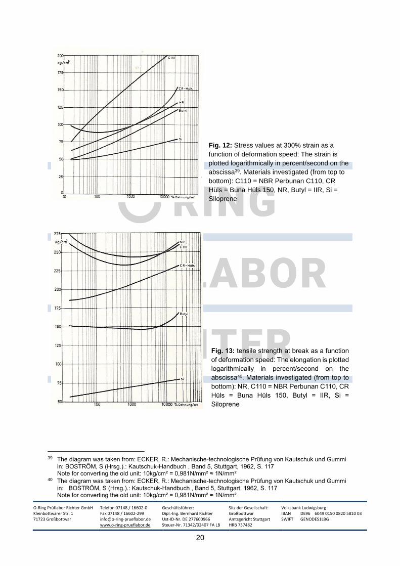
An important study on the influence of deformation speed was carried out by FROMANDI and
staff.38. A test device was used which allowed deformation rates of up to 20m/s. Compounds
with the following basic elastomers were investigated: NR, SBR, NBR, IIR and VMQ.
Generally, the stress value σ300 , meaning the stress at 300% elongation, increased with
increasing deformation speed for almost all elastomers (except CR).
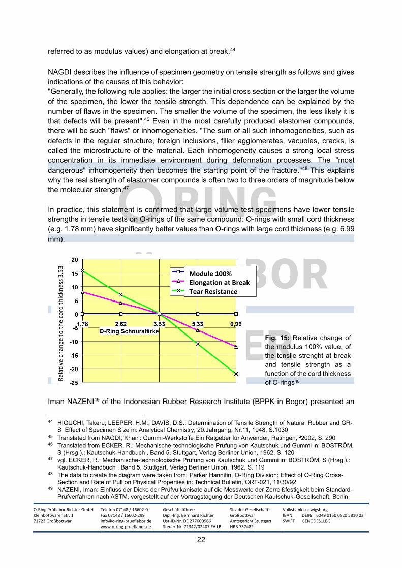
The elongation at break increased with increasing deformation speed, except for elastomers,
which tend to crystallize at certain deformations (e.g. natural rubber and polychlorobutadiene).
They reached a minimum at approx. 10,000% deformation / second, only to rise again
afterwards.
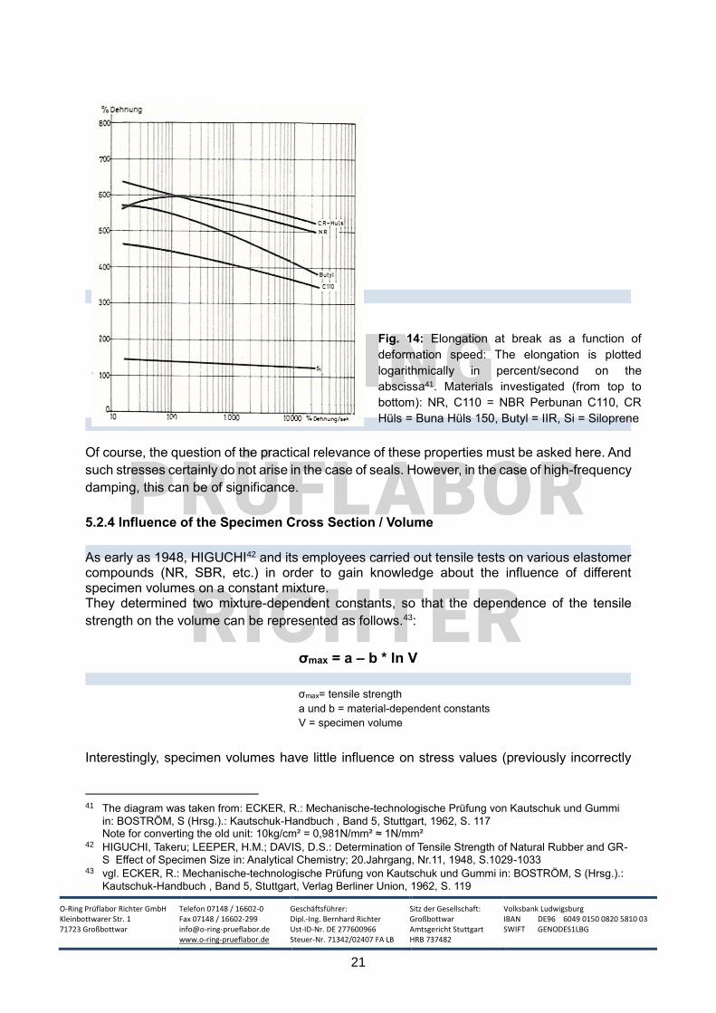
The tensile strength at break decreased slightly with increasing speed in most cases, except
for VMQ, which showed constant values.
36 vgl. BROWN, Roger: Physical Testing of Rubber, New York, 42006, S. 140 37 vgl. http://www.bungeesports.de/springer/faq1.htm (abegrufen am 27.06.2014) 38 vgl. ECKER, R.: Mechanische-technologische Prüfung von Kautschuk und Gummi in: BOSTRÖM, S (Hrsg.).:
Kautschuk-Handbuch , Band 5, Stuttgart, 1962, S. 115 ff.
O-Ring Prüflabor Richter GmbH Kleinbottwarer Str. 1 71723 Großbottwar
Telefon 07148 / 16602-0 Fax 07148 / 16602-299 [email protected] www.o-ring-prueflabor.de
Geschäftsführer: Dipl.-Ing. Bernhard Richter Ust-ID-Nr. DE 277600966 Steuer-Nr. 71342/02407 FA LB
Sitz der Gesellschaft: Großbottwar Amtsgericht Stuttgart HRB 737482
Volksbank Ludwigsburg IBAN DE96 6049 0150 0820 5810 03 SWIFT GENODES1LBG
20
Fig. 12: Stress values at 300% strain as a
function of deformation speed: The strain is
plotted logarithmically in percent/second on the
abscissa39. Materials investigated (from top to
bottom): C110 = NBR Perbunan C110, CR
Hüls = Buna Hüls 150, NR, Butyl = IIR, Si =
Siloprene
Fig. 13: tensile strength at break as a function
of deformation speed: The elongation is plotted
logarithmically in percent/second on the
abscissa40. Materials investigated (from top to
bottom): NR, C110 = NBR Perbunan C110, CR
Hüls = Buna Hüls 150, Butyl = IIR, Si =
Siloprene
39 The diagram was taken from: ECKER, R.: Mechanische-technologische Prüfung von Kautschuk und Gummi
in: BOSTRÖM, S (Hrsg.).: Kautschuk-Handbuch , Band 5, Stuttgart, 1962, S. 117 Note for converting the old unit: 10kg/cm² = 0,981N/mm² ≈ 1N/mm²
40 The diagram was taken from: ECKER, R.: Mechanische-technologische Prüfung von Kautschuk und Gummi
in: BOSTRÖM, S (Hrsg.).: Kautschuk-Handbuch , Band 5, Stuttgart, 1962, S. 117 Note for converting the old unit: 10kg/cm² = 0,981N/mm² ≈ 1N/mm²
O-Ring Prüflabor Richter GmbH Kleinbottwarer Str. 1 71723 Großbottwar
Telefon 07148 / 16602-0 Fax 07148 / 16602-299 [email protected] www.o-ring-prueflabor.de
Geschäftsführer: Dipl.-Ing. Bernhard Richter Ust-ID-Nr. DE 277600966 Steuer-Nr. 71342/02407 FA LB
Sitz der Gesellschaft: Großbottwar Amtsgericht Stuttgart HRB 737482
Volksbank Ludwigsburg IBAN DE96 6049 0150 0820 5810 03 SWIFT GENODES1LBG
21
Fig. 14: Elongation at break as a function of
deformation speed: The elongation is plotted
logarithmically in percent/second on the
abscissa41. Materials investigated (from top to
bottom): NR, C110 = NBR Perbunan C110, CR
Hüls = Buna Hüls 150, Butyl = IIR, Si = Siloprene
Of course, the question of the practical relevance of these properties must be asked here. And
such stresses certainly do not arise in the case of seals. However, in the case of high-frequency
damping, this can be of significance.
5.2.4 Influence of the Specimen Cross Section / Volume
As early as 1948, HIGUCHI42 and its employees carried out tensile tests on various elastomer compounds (NR, SBR, etc.) in order to gain knowledge about the influence of different specimen volumes on a constant mixture. They determined two mixture-dependent constants, so that the dependence of the tensile
strength on the volume can be represented as follows.43:
σmax = a – b * ln V
σmax= tensile strength a und b = material-dependent constants
V = specimen volume
Interestingly, specimen volumes have little influence on stress values (previously incorrectly
41 The diagram was taken from: ECKER, R.: Mechanische-technologische Prüfung von Kautschuk und Gummi
in: BOSTRÖM, S (Hrsg.).: Kautschuk-Handbuch , Band 5, Stuttgart, 1962, S. 117 Note for converting the old unit: 10kg/cm² = 0,981N/mm² ≈ 1N/mm²
42 HIGUCHI, Takeru; LEEPER, H.M.; DAVIS, D.S.: Determination of Tensile Strength of Natural Rubber and GR-
S Effect of Specimen Size in: Analytical Chemistry; 20.Jahrgang, Nr.11, 1948, S.1029-1033 43 vgl. ECKER, R.: Mechanische-technologische Prüfung von Kautschuk und Gummi in: BOSTRÖM, S (Hrsg.).:
Kautschuk-Handbuch , Band 5, Stuttgart, Verlag Berliner Union, 1962, S. 119
O-Ring Prüflabor Richter GmbH Kleinbottwarer Str. 1 71723 Großbottwar
Telefon 07148 / 16602-0 Fax 07148 / 16602-299 [email protected] www.o-ring-prueflabor.de
Geschäftsführer: Dipl.-Ing. Bernhard Richter Ust-ID-Nr. DE 277600966 Steuer-Nr. 71342/02407 FA LB
Sitz der Gesellschaft: Großbottwar Amtsgericht Stuttgart HRB 737482
Volksbank Ludwigsburg IBAN DE96 6049 0150 0820 5810 03 SWIFT GENODES1LBG
22
referred to as modulus values) and elongation at break.44
NAGDI describes the influence of specimen geometry on tensile strength as follows and gives
indications of the causes of this behavior:
"Generally, the following rule applies: the larger the initial cross section or the larger the volume
of the specimen, the lower the tensile strength. This dependence can be explained by the
number of flaws in the specimen. The smaller the volume of the specimen, the less likely it is
that defects will be present".45 Even in the most carefully produced elastomer compounds,
there will be such "flaws" or inhomogeneities. "The sum of all such inhomogeneities, such as
defects in the regular structure, foreign inclusions, filler agglomerates, vacuoles, cracks, is
called the microstructure of the material. Each inhomogeneity causes a strong local stress
concentration in its immediate environment during deformation processes. The "most
dangerous" inhomogeneity then becomes the starting point of the fracture."46 This explains
why the real strength of elastomer compounds is often two to three orders of magnitude below
the molecular strength.47
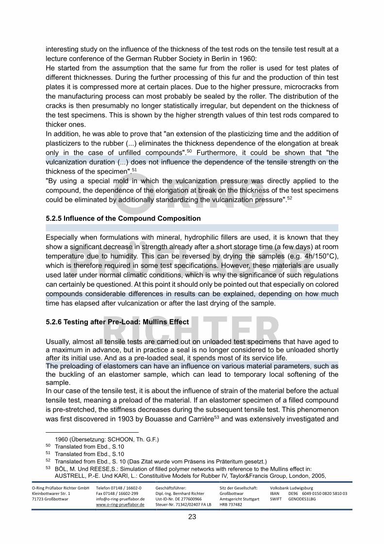
In practice, this statement is confirmed that large volume test specimens have lower tensile
strengths in tensile tests on O-rings of the same compound: O-rings with small cord thickness
(e.g. 1.78 mm) have significantly better values than O-rings with large cord thickness (e.g. 6.99
mm).
Fig. 15: Relative change of
the modulus 100% value, of
the tensile strenght at break
and tensile strength as a
function of the cord thickness
of O-rings48
Iman NAZENI49 of the Indonesian Rubber Research Institute (BPPK in Bogor) presented an
44 HIGUCHI, Takeru; LEEPER, H.M.; DAVIS, D.S.: Determination of Tensile Strength of Natural Rubber and GR-
S Effect of Specimen Size in: Analytical Chemistry; 20.Jahrgang, Nr.11, 1948, S.1030 45 Translated from NAGDI, Khairi: Gummi-Werkstoffe Ein Ratgeber für Anwender, Ratingen, ²2002, S. 290 46 Translated from ECKER, R.: Mechanische-technologische Prüfung von Kautschuk und Gummi in: BOSTRÖM,
S (Hrsg.).: Kautschuk-Handbuch , Band 5, Stuttgart, Verlag Berliner Union, 1962, S. 120 47 vgl. ECKER, R.: Mechanische-technologische Prüfung von Kautschuk und Gummi in: BOSTRÖM, S (Hrsg.).:
Kautschuk-Handbuch , Band 5, Stuttgart, Verlag Berliner Union, 1962, S. 119 48 The data to create the diagram were taken from: Parker Hannifin, O-Ring Division: Effect of O-Ring Cross-
Section and Rate of Pull on Physical Properties in: Technical Bulletin, ORT-021, 11/30/92 49 NAZENI, Iman: Einfluss der Dicke der Prüfvulkanisate auf die Messwerte der Zerreißfestigkeit beim Standard-
Prüfverfahren nach ASTM, vorgestellt auf der Vortragstagung der Deutschen Kautschuk-Gesellschaft, Berlin,
Module 100% Elongation at Break Tear Resistance
Rel
ativ
e ch
ange
to
th
e co
rd t
hic
knes
s 3
.53
O-Ring Prüflabor Richter GmbH Kleinbottwarer Str. 1 71723 Großbottwar
Telefon 07148 / 16602-0 Fax 07148 / 16602-299 [email protected] www.o-ring-prueflabor.de
Geschäftsführer: Dipl.-Ing. Bernhard Richter Ust-ID-Nr. DE 277600966 Steuer-Nr. 71342/02407 FA LB
Sitz der Gesellschaft: Großbottwar Amtsgericht Stuttgart HRB 737482
Volksbank Ludwigsburg IBAN DE96 6049 0150 0820 5810 03 SWIFT GENODES1LBG
23
interesting study on the influence of the thickness of the test rods on the tensile test result at a
lecture conference of the German Rubber Society in Berlin in 1960:
He started from the assumption that the same fur from the roller is used for test plates of
different thicknesses. During the further processing of this fur and the production of thin test
plates it is compressed more at certain places. Due to the higher pressure, microcracks from
the manufacturing process can most probably be sealed by the roller. The distribution of the
cracks is then presumably no longer statistically irregular, but dependent on the thickness of
the test specimens. This is shown by the higher strength values of thin test rods compared to
thicker ones.
In addition, he was able to prove that "an extension of the plasticizing time and the addition of
plasticizers to the rubber (...) eliminates the thickness dependence of the elongation at break
only in the case of unfilled compounds".50 Furthermore, it could be shown that "the
vulcanization duration (...) does not influence the dependence of the tensile strength on the
thickness of the specimen".51
"By using a special mold in which the vulcanization pressure was directly applied to the
compound, the dependence of the elongation at break on the thickness of the test specimens
could be eliminated by additionally standardizing the vulcanization pressure".52
5.2.5 Influence of the Compound Composition
Especially when formulations with mineral, hydrophilic fillers are used, it is known that they
show a significant decrease in strength already after a short storage time (a few days) at room
temperature due to humidity. This can be reversed by drying the samples (e.g. 4h/150°C),
which is therefore required in some test specifications. However, these materials are usually
used later under normal climatic conditions, which is why the significance of such regulations
can certainly be questioned. At this point it should only be pointed out that especially on colored
compounds considerable differences in results can be explained, depending on how much
time has elapsed after vulcanization or after the last drying of the sample.
5.2.6 Testing after Pre-Load: Mullins Effect
Usually, almost all tensile tests are carried out on unloaded test specimens that have aged to a maximum in advance, but in practice a seal is no longer considered to be unloaded shortly after its initial use. And as a pre-loaded seal, it spends most of its service life. The preloading of elastomers can have an influence on various material parameters, such as the buckling of an elastomer sample, which can lead to temporary local softening of the sample. In our case of the tensile test, it is about the influence of strain of the material before the actual
tensile test, meaning a preload of the material. If an elastomer specimen of a filled compound
is pre-stretched, the stiffness decreases during the subsequent tensile test. This phenomenon
was first discovered in 1903 by Bouasse and Carrière53 and was extensively investigated and
1960 (Übersetzung: SCHOON, Th. G.F.)
50 Translated from Ebd., S.10 51 Translated from Ebd., S.10 52 Translated from Ebd., S. 10 (Das Zitat wurde vom Präsens ins Präteritum gesetzt.) 53 BÖL, M. Und REESE,S.: Simulation of filled polymer networks with reference to the Mullins effect in:
AUSTRELL, P.-E. Und KARI, L.: Constituitive Models for Rubber IV, Taylor&Francis Group, London, 2005,
O-Ring Prüflabor Richter GmbH Kleinbottwarer Str. 1 71723 Großbottwar
Telefon 07148 / 16602-0 Fax 07148 / 16602-299 [email protected] www.o-ring-prueflabor.de
Geschäftsführer: Dipl.-Ing. Bernhard Richter Ust-ID-Nr. DE 277600966 Steuer-Nr. 71342/02407 FA LB
Sitz der Gesellschaft: Großbottwar Amtsgericht Stuttgart HRB 737482
Volksbank Ludwigsburg IBAN DE96 6049 0150 0820 5810 03 SWIFT GENODES1LBG
24
described by MULLINS54 in 1947.
The so-called "Mullin Effect" can also occur in rubbers that tend to crystallize as a result of
elongation. "Here, the crystallites behave like filler particles (self-reinforcement). The reversible
conformational changes of the network allow a recovery from the stress softened state, which
occurs only very slowly".55
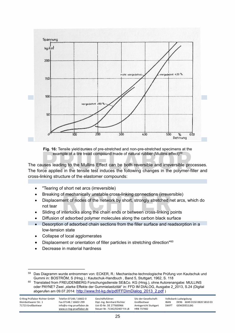
The following diagram56 clearly shows this effect: The specimen, which was pre-stretched by
280% in advance, shows a less stiff material characteristic in the second tensile test than the
unloaded specimen. The softening is increased by an even higher preload (420%). Another
interesting effect is that the preloaded mixture merges approximately into the curve of the
unloaded compound as soon as the degree of preload is exceeded (here 280% or 420%). The
stiffness of the material can be determined by the gradient of the respective stress-strain
curves. “The gradient of the ‘softened’ stress-strain curves for small strains is initially smaller,
but then larger than the gradient of the unloaded curve. The stiffness of a body is given by the
secant stiffness DF/Ds between two measuring points. Therefore, depending on whether one
measures in the steep or flat area of the ‘softened’ stress-strain curve, there is a higher or
lower stiffness compared to the unloaded curve (Mullin's paradox)."57
If the elongation is repeated several times and the maximum elongation is not exceeded, the
stress elongation curve stabilizes, and this effect is relatively constant.58 So there is no
continuous deterioration.
S.168
54 MULLINS, L.: Effect of stretching on the properties of rubber in: Journal of Rubber Research 16, 1947, S.275-
289 55 Translated from FREUDENBERG Forschungsdienste SE&Co. KG (Hrsg.), ohne Autorenangabe: MULLINS
oder PAYNE? Zwei „starke Effekte der Gummielastizität“ in: FFD IM DIALOG, Ausgabe 2_2013, S.25 (Digital
abgerufen am 09.07.2014: http://www.fnt-kg.de/pdf/FFDimDialog_2013_2.pdf ) 56 The diagram was taken from : ECKER, R.: Mechanische-technologische Prüfung von Kautschuk und Gummi
in: BOSTRÖM, S (Hrsg.).: Kautschuk-Handbuch , Band 5, Stuttgart, Verlag Berliner Union, 1962, S. 118 57 FREUDENBERG Forschungsdienste SE&Co. KG (Hrsg.), ohne Autorenangabe: MULLINS oder PAYNE? Zwei
„starke Effekte der Gummielastizität“ in: FFD IM DIALOG, Ausgabe 2_2013, S.23f. (Digital abgerufen am
09.07.2014: http://www.fnt-kg.de/pdf/FFDimDialog_2013_2.pdf ) 58 vgl. PAIGE, Ryan E. und MARS, Will V.: Implications of the Mullins Effect on the Stiffness of a Pre-loaded
Rubber Component vorgetragen bei: 2004 ABAQUS Users’ Conference, S.2
(Webseite abgerufen am 09.07.2014: http://www.axelproducts.com/downloads/PaigeMars.pdf )
O-Ring Prüflabor Richter GmbH Kleinbottwarer Str. 1 71723 Großbottwar
Telefon 07148 / 16602-0 Fax 07148 / 16602-299 [email protected] www.o-ring-prueflabor.de
Geschäftsführer: Dipl.-Ing. Bernhard Richter Ust-ID-Nr. DE 277600966 Steuer-Nr. 71342/02407 FA LB
Sitz der Gesellschaft: Großbottwar Amtsgericht Stuttgart HRB 737482
Volksbank Ludwigsburg IBAN DE96 6049 0150 0820 5810 03 SWIFT GENODES1LBG
25
Fig. 16: Tensile yield curves of pre-stretched and non-pre-stretched specimens at the
example of a tire tread compound made of natural rubber (Mullins effect)59
The causes leading to the Mullins Effect can be both reversible and irreversible processes.
The force applied in the tensile test induces the following changes in the polymer-filler and
cross-linking structure of the elastomer compounds:
"Tearing of short net arcs (irreversible)
Breaking of mechanically unstable cross-linking connections (irreversible)
Displacement of nodes of the network by short, strongly stretched net arcs, which do
not tear
Sliding of interlocks along the chain ends or between cross-linking points
Diffusion of adsorbed polymer molecules along the carbon black surface
Desorption of adsorbed chain sections from the filler surface and readsorption in a
low-tension state
Collapse of local agglomerates
Displacement or orientation of filler particles in stretching direction"60
Decrease in material hardness
59 Das Diagramm wurde entnommen von: ECKER, R.: Mechanische-technologische Prüfung von Kautschuk und
Gummi in: BOSTRÖM, S (Hrsg.).: Kautschuk-Handbuch , Band 5, Stuttgart, 1962, S. 118 60 Translated from FREUDENBERG Forschungsdienste SE&Co. KG (Hrsg.), ohne Autorenangabe: MULLINS
oder PAYNE? Zwei „starke Effekte der Gummielastizität“ in: FFD IM DIALOG, Ausgabe 2_2013, S.24 (Digital
abgerufen am 09.07.2014: http://www.fnt-kg.de/pdf/FFDimDialog_2013_2.pdf )
O-Ring Prüflabor Richter GmbH Kleinbottwarer Str. 1 71723 Großbottwar
Telefon 07148 / 16602-0 Fax 07148 / 16602-299 [email protected] www.o-ring-prueflabor.de
Geschäftsführer: Dipl.-Ing. Bernhard Richter Ust-ID-Nr. DE 277600966 Steuer-Nr. 71342/02407 FA LB
Sitz der Gesellschaft: Großbottwar Amtsgericht Stuttgart HRB 737482
Volksbank Ludwigsburg IBAN DE96 6049 0150 0820 5810 03 SWIFT GENODES1LBG
26
DICK61 describes the phenomenon that often elastomer compounds reinforced by fillers, which
have been pre-stretched and are then tested after a resting phase until they rupture, exhibit
higher modulus values and tensile strengths than samples that have not been preloaded. Since
stress-strain cycles frequently occur on components in practice, this property is sometimes
advantageous.
In practice, knowledge of the Mullins Effect is particularly important in the design and
construction of damping elements that are subject to constant preloading, such as engine
mounts. The material characteristic of the elastomer component can be changed by the
preload via the Mullins Effect.62
When determining the spring stiffness of prefabricated components, it is recommended to run
several load cycles in order to be able to measure reproducibly. This history must of course be
noted in the test documentation.63
5.2.7 Usual Accuracies for Tensile Tests
Towards the end of DIN 53504 there is a chapter dealing with the precision64 of this process.
In 1989, 17 laboratories took part in an interlaboratory test for tensile testing. The results for
tensile strength, tensile strenght at break and stress value 100% were compared and
evaluated.
There aren't any conclusions about the materials investigated, instead they are merely divided
into three strength levels.
It can be assumed that interlaboratory comparisons for a DIN standard meet the highest
requirements, both with regard to the mixtures used (known formulations, ideal mixing and
production conditions of the test plates, etc.) and the laboratory side (calibrated state-of-the-
art test equipment, trained and experienced personnel).
It is, therefore, not possible to generally use the following results as a benchmark for the
accuracy of tensile tests. Unfortunately, it can be assumed that this precision cannot be
achieved in standard tests with elastomers from classic rubber production. In addition, there
are elastomers that tend to have larger scatter widths due to their compound structure or
hardness levels. This effect was apparently deliberately excluded in the present study (no
mention of the base elastomer or hardness of the compounds investigated).
61 DICK, John S.: Rubber Technology – Compounding and Testing for Performance, München, 2001, S.49 62 vgl. PAIGE, Ryan E. und MARS, Will V.: Implications of the Mullins Effect on the Stiffness of a Pre-loaded
Rubber Component vorgetragen bei: 2004 ABAQUS Users’ Conference, S.1f.
(Webseite abgerufen am 09.07.2014: http://www.axelproducts.com/downloads/PaigeMars.pdf ) 63 FREUDENBERG Forschungsdienste SE&Co. KG (Hrsg.), ohne Autorenangabe: MULLINS oder PAYNE? Zwei
„starke Effekte der Gummielastizität“ in: FFD IM DIALOG, Ausgabe 2_2013, S.25 (Digital abgerufen am
09.07.2014: http://www.fnt-kg.de/pdf/FFDimDialog_2013_2.pdf ) 64 This term is defined as follows: „Die Präzision ist gemäß DIN ISO 5725 [1] definiert als „Ausmaß der
gegenseitigen Annäherung zwischen unabhängigen Ermittlungsergebnissen, die unter festgelegten Bedingungen gewonnen sind“.“ zitiert von: Amtl. Sammlung § 35 LMBG Statistik Mai 2003 „Planung und statistische Auswertung von Ringversuchen zur Methodenvalidierung“, Seite 2, Dokument abgerufen am 18.09.2014: http://www.beuth.de/sixcms_upload/media/2359/lmbg35_mai_2003.pdf
O-Ring Prüflabor Richter GmbH Kleinbottwarer Str. 1 71723 Großbottwar
Telefon 07148 / 16602-0 Fax 07148 / 16602-299 [email protected] www.o-ring-prueflabor.de
Geschäftsführer: Dipl.-Ing. Bernhard Richter Ust-ID-Nr. DE 277600966 Steuer-Nr. 71342/02407 FA LB
Sitz der Gesellschaft: Großbottwar Amtsgericht Stuttgart HRB 737482
Volksbank Ludwigsburg IBAN DE96 6049 0150 0820 5810 03 SWIFT GENODES1LBG
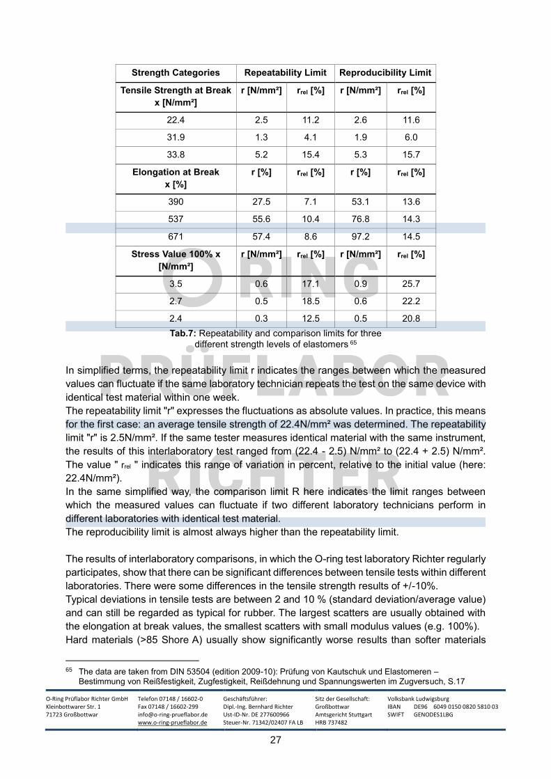
27
Strength Categories Repeatability Limit Reproducibility Limit
Tensile Strength at Break
x [N/mm²]
r [N/mm²] rrel [%] r [N/mm²] rrel [%]
22.4 2.5 11.2 2.6 11.6
31.9 1.3 4.1 1.9 6.0
33.8 5.2 15.4 5.3 15.7
Elongation at Break
x [%]
r [%] rrel [%] r [%] rrel [%]
390 27.5 7.1 53.1 13.6
537 55.6 10.4 76.8 14.3
671 57.4 8.6 97.2 14.5
Stress Value 100% x
[N/mm²]
r [N/mm²] rrel [%] r [N/mm²] rrel [%]
3.5 0.6 17.1 0.9 25.7
2.7 0.5 18.5 0.6 22.2
2.4 0.3 12.5 0.5 20.8
Tab.7: Repeatability and comparison limits for three
different strength levels of elastomers 65
In simplified terms, the repeatability limit r indicates the ranges between which the measured
values can fluctuate if the same laboratory technician repeats the test on the same device with
identical test material within one week.
The repeatability limit "r" expresses the fluctuations as absolute values. In practice, this means
for the first case: an average tensile strength of 22.4N/mm² was determined. The repeatability
limit "r" is 2.5N/mm². If the same tester measures identical material with the same instrument,
the results of this interlaboratory test ranged from (22.4 - 2.5) N/mm² to (22.4 + 2.5) N/mm².
The value " rrel " indicates this range of variation in percent, relative to the initial value (here:
22.4N/mm²).
In the same simplified way, the comparison limit R here indicates the limit ranges between
which the measured values can fluctuate if two different laboratory technicians perform in
different laboratories with identical test material.
The reproducibility limit is almost always higher than the repeatability limit.
The results of interlaboratory comparisons, in which the O-ring test laboratory Richter regularly
participates, show that there can be significant differences between tensile tests within different
laboratories. There were some differences in the tensile strength results of +/-10%.
Typical deviations in tensile tests are between 2 and 10 % (standard deviation/average value)
and can still be regarded as typical for rubber. The largest scatters are usually obtained with
the elongation at break values, the smallest scatters with small modulus values (e.g. 100%).
Hard materials (>85 Shore A) usually show significantly worse results than softer materials
65 The data are taken from DIN 53504 (edition 2009-10): Prüfung von Kautschuk und Elastomeren –
Bestimmung von Reißfestigkeit, Zugfestigkeit, Reißdehnung und Spannungswerten im Zugversuch, S.17

O-Ring Prüflabor Richter GmbH Kleinbottwarer Str. 1 71723 Großbottwar
Telefon 07148 / 16602-0 Fax 07148 / 16602-299 [email protected] www.o-ring-prueflabor.de
Geschäftsführer: Dipl.-Ing. Bernhard Richter Ust-ID-Nr. DE 277600966 Steuer-Nr. 71342/02407 FA LB
Sitz der Gesellschaft: Großbottwar Amtsgericht Stuttgart HRB 737482
Volksbank Ludwigsburg IBAN DE96 6049 0150 0820 5810 03 SWIFT GENODES1LBG
28
(50-70 Shore A). If these scatters exceed 15%, it is a clear indication of a manufacturing defect
in the samples.
![Optimierung der Kraftduktilitäts-Prüfung von PmB 1. … · 2012-09-25 · B 60/70 B 80/100 B 120/150 PmB, Elastomer PmB, Plastomer PmB, Elastomer Energie [J/cm 2] H2 ASTM DIN SHRP](https://img.pdfslide.org/doc/110x75/5e798dd2de042a314f2d8a29/optimierung-der-kraftduktilitts-prfung-von-pmb-1-2012-09-25-b-6070-b-80100.jpg)