Embed Size (px)
Citation preview
7/25/2019 File-1361381461 wer w
http://slidepdf.com/reader/full/file-1361381461-wer-w 1/16
5111
Variable Speed Drive for
pumps and fans
SINAMICS
G120P
• Power range: 0.37 kW to 75 kW (IP20) / 90 kW (IP55)
• Voltage range: 3AC 380…480 V
• Standard with RS485: /USS, Modbus/RTU, BACnetMS/TP
• Optional control units with PROFIBUS DP, CANopen
• 4 internal PID controllers
• High degree of protection IP55/UL Type 12, and for control cabinet IP20
• With EMC filter class A (C2) or class B (C1)
• Modular design of power and control electronics
Use
Variable speed drive for energy-optimized speed control of pumps and fan motors in
building control applications:
• Speed control of supply and extract air fans in air handling units based on demand
• Speed control of circulating pumps in HVAC plants based on demand
• Increased pressure and control of pump levels
CM2N5111en
2012-12-11 Building Technologies
7/25/2019 File-1361381461 wer w
http://slidepdf.com/reader/full/file-1361381461-wer-w 2/16
Functions
Specially designed functions for pumps and fans are already implemented:
• Automatic restart
application resumes start up after a power outage or error
• Flying restart
switch on drive while motor is running
• ECO mode
Energy savings by automatically adapting the motor current to prevailing load
conditions, for uses with less dynamics and a constant speed setpoint
• Motor staging
One VSD is used to control up to 4 motors depending on the flow rate, for example,
for strongly varying volumetric flows
• Hibernation
automatic sleep mode to optimize control and energy use
• 4 integrated PID controllers
to control drive speed based on pressure, temperature, flow rates, levels, air quality,
or other process variables
• Essential Service Mode (ESM) for emergency operationspecial inverter operating mode that increase availability of the drive system in the
event of fire
• Multi-zone controller
− Controls a zone for pressure or temperature with up to 3 sensors, or
− Control of two independent zones with one sensor each
• Bypass mode
automatic switchover to mains operation upon reaching the setpoint
• Freely programmable 7-day digital time switches (3)
• Real-time clock
for process control based on time, e.g. temperature setpoint at night for heating
control• Freely programmable logical function blocks
for mapping simple PLC-like functionality
• Motor temperature monitoring with either temperature sensor or contact via PTC,
KTY and ThermoClick Sensor)
− Overcurrent protection
− Load torque monitoring
− Overvoltage protection (Vdc_max controller)
• Braking function using DC braking
Types
SINAMICS G120P refers to the combination of the SINAMICS Control Unit CU230P-2
BT with the SINAMICS Power Module PM230 matched to the specific pumps and fans
as well as operator panel or blanking cover. The Operator panel or blanking cover is
not part of delivery and must be ordered separately.
Basic design
The CU230P-2 is available in the following versions:
• CU230P-2 BT with RS485 interface for USS, Modbus RTU and BACnet MS/TP.
Included in the delivery of the G120P bundle.
• CU230P-2 CAN with CANopen interface. Order separately.
• CU230P-2 DP with PROFIBUS DP interface. Order separately.
The Power Modul PM230 is available in the following versions:
• IP55 with integrated EMC filter A (C2) or integrated EMC filter B (C1)
• IP20 with integrated EMC filter A (C2) or unfiltered with external EMC filter B (C1)
2 / 16
Siemens Variable Speed Drive for pumps and fans G120P CM2N5111en
Building Technologies 2012-12-11
7/25/2019 File-1361381461 wer w
http://slidepdf.com/reader/full/file-1361381461-wer-w 3/16
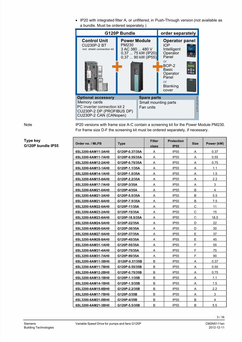
• IP20 with integrated filter A, or unfiltered, in Push-Through version (not available as
a bundle. Must be ordered seperately.)
Control UnitCU230P-2 BT
CU230P-2 DP (PROFIBUS DP)CU230P-2 CAN (CANopen)
Power ModulePM2303 AC 380 ... 480 V0,37 ... 75 kW (IP20)
Operator panelIOPIntelligentOperatorPanelor BOP-2BasicOperatorPanelor Blankingcover
Memory cards Small mounting parts
Fan units G_
D 0 1 1_
E N_
0 0 3 1 6 a
Optional accessory Spare parts
++
incl. shield connection kit
G120P Bundle order separately
0,37 ... 90 kW (IP55)
IP20 versions with frame size A-C contain a screening kit for the Power Module PM230.
For frame size D-F the screening kit must be ordered separately, if necessary.
Note
Order no. / MLFB Type Filter
class
Protection
IP55 Size Power (kW)
6SL3200-6AM11-3AH0 G120P-0.37/35A A IP55 A 0.37
6SL3200-6AM11-7AH0 G120P-0.55/35A A IP55 A 0.55
6SL3200-6AM12-2AH0 G120P-0.75/35A A IP55 A 0.75
6SL3200-6AM13-1AH0 G120P-1.1/35A A IP55 A 1.1
6SL3200-6AM14-1AH0 G120P-1.5/35A A IP55 A 1.5
6SL3200-6AM15-8AH0 G120P-2.2/35A A IP55 A 2.26SL3200-6AM17-7AH0 G120P-3/35A A IP55 A 3
6SL3200-6AM21-0AH0 G120P-4/35A A IP55 B 4
6SL3200-6AM21-3AH0 G120P-5.5/35A A IP55 B 5.5
6SL3200-6AM21-8AH0 G120P-7.5/35A A IP55 B 7.5
6SL3200-6AM22-6AH0 G120P-11/35A A IP55 C 11
6SL3200-6AM23-2AH0 G120P-15/35A A IP55 C 15
6SL3200-6AM23-8AH0 G120P-18.5/35A A IP55 C 18.5
6SL3200-6AM24-5AH0 G120P-22/35A A IP55 D 22
6SL3200-6AM26-0AH0 G120P-30/35A A IP55 D 30
6SL3200-6AM27-5AH0 G120P-37/35A A IP55 E 37
6SL3200-6AM28-8AH0 G120P-45/35A A IP55 E 45
6SL3200-6AM31-1AH0 G120P-55/35A A IP55 F 55
6SL3200-6AM31-4AH0 G120P-75/35A A IP55 F 75
6SL3200-6AM31-7AH0 G120P-90/35A A IP55 F 90
6SL3200-6AM11-3BH0 G120P-0.37/35B B IP55 A 0.37
6SL3200-6AM11-7BH0 G120P-0.55/35B B IP55 A 0.55
6SL3200-6AM12-2BH0 G120P-0.75/35B B IP55 A 0.75
6SL3200-6AM13-1BH0 G120P-1.1/35B B IP55 A 1.1
6SL3200-6AM14-1BH0 G120P-1.5/35B B IP55 A 1.5
6SL3200-6AM15-8BH0 G120P-2.2/35B B IP55 A 2.2
6SL3200-6AM17-7BH0 G120P-3/35B B IP55 A 3
6SL3200-6AM21-0BH0 G120P-4/35B B IP55 B 4
6SL3200-6AM21-3BH0 G120P-5.5/35B B IP55 B 5.5
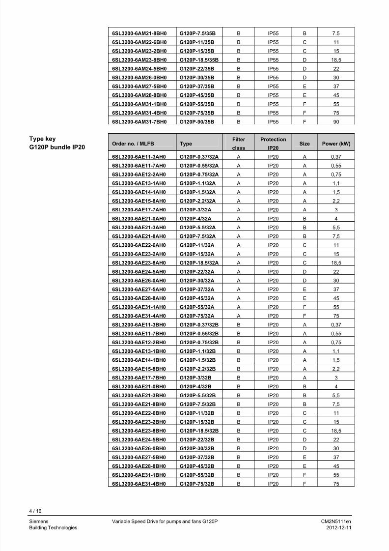
Type key
G120P bundle IP55
3 / 16
Siemens Variable Speed Drive for pumps and fans G120P CM2N5111en
Building Technologies 2012-12-11
7/25/2019 File-1361381461 wer w
http://slidepdf.com/reader/full/file-1361381461-wer-w 4/16
6SL3200-6AM21-8BH0 G120P-7.5/35B B IP55 B 7.5
6SL3200-6AM22-6BH0 G120P-11/35B B IP55 C 11
6SL3200-6AM23-2BH0 G120P-15/35B B IP55 C 15
6SL3200-6AM23-8BH0 G120P-18.5/35B B IP55 D 18.5
6SL3200-6AM24-5BH0 G120P-22/35B B IP55 D 22
6SL3200-6AM26-0BH0 G120P-30/35B B IP55 D 30
6SL3200-6AM27-5BH0 G120P-37/35B B IP55 E 37
6SL3200-6AM28-8BH0 G120P-45/35B B IP55 E 456SL3200-6AM31-1BH0 G120P-55/35B B IP55 F 55
6SL3200-6AM31-4BH0 G120P-75/35B B IP55 F 75
6SL3200-6AM31-7BH0 G120P-90/35B B IP55 F 90
Order no. / MLFB TypeFilter
class
Protection
IP20Size Power (kW)
6SL3200-6AE11-3AH0 G120P-0.37/32A A IP20 A 0,37
6SL3200-6AE11-7AH0 G120P-0.55/32A A IP20 A 0,55
6SL3200-6AE12-2AH0 G120P-0.75/32A A IP20 A 0,75
6SL3200-6AE13-1AH0 G120P-1.1/32A A IP20 A 1,1
6SL3200-6AE14-1AH0 G120P-1.5/32A A IP20 A 1,56SL3200-6AE15-8AH0 G120P-2.2/32A A IP20 A 2,2
6SL3200-6AE17-7AH0 G120P-3/32A A IP20 A 3
6SL3200-6AE21-0AH0 G120P-4/32A A IP20 B 4
6SL3200-6AE21-3AH0 G120P-5.5/32A A IP20 B 5,5
6SL3200-6AE21-8AH0 G120P-7.5/32A A IP20 B 7,5
6SL3200-6AE22-6AH0 G120P-11/32A A IP20 C 11
6SL3200-6AE23-2AH0 G120P-15/32A A IP20 C 15
6SL3200-6AE23-8AH0 G120P-18.5/32A A IP20 C 18,5
6SL3200-6AE24-5AH0 G120P-22/32A A IP20 D 22
6SL3200-6AE26-0AH0 G120P-30/32A A IP20 D 30
6SL3200-6AE27-5AH0 G120P-37/32A A IP20 E 37
6SL3200-6AE28-8AH0 G120P-45/32A A IP20 E 45
6SL3200-6AE31-1AH0 G120P-55/32A A IP20 F 55
6SL3200-6AE31-4AH0 G120P-75/32A A IP20 F 75
6SL3200-6AE11-3BH0 G120P-0.37/32B B IP20 A 0,37
6SL3200-6AE11-7BH0 G120P-0.55/32B B IP20 A 0,55
6SL3200-6AE12-2BH0 G120P-0.75/32B B IP20 A 0,75
6SL3200-6AE13-1BH0 G120P-1.1/32B B IP20 A 1,1
6SL3200-6AE14-1BH0 G120P-1.5/32B B IP20 A 1,5
6SL3200-6AE15-8BH0 G120P-2.2/32B B IP20 A 2,2
6SL3200-6AE17-7BH0 G120P-3/32B B IP20 A 3
6SL3200-6AE21-0BH0 G120P-4/32B B IP20 B 4
6SL3200-6AE21-3BH0 G120P-5.5/32B B IP20 B 5,5
6SL3200-6AE21-8BH0 G120P-7.5/32B B IP20 B 7,5
6SL3200-6AE22-6BH0 G120P-11/32B B IP20 C 11
6SL3200-6AE23-2BH0 G120P-15/32B B IP20 C 15
6SL3200-6AE23-8BH0 G120P-18.5/32B B IP20 C 18,5
6SL3200-6AE24-5BH0 G120P-22/32B B IP20 D 22
6SL3200-6AE26-0BH0 G120P-30/32B B IP20 D 30
6SL3200-6AE27-5BH0 G120P-37/32B B IP20 E 37
6SL3200-6AE28-8BH0 G120P-45/32B B IP20 E 45
6SL3200-6AE31-1BH0 G120P-55/32B B IP20 F 55
6SL3200-6AE31-4BH0 G120P-75/32B B IP20 F 75
Type key
G120P bundle IP20
4 / 16
Siemens Variable Speed Drive for pumps and fans G120P CM2N5111en
Building Technologies 2012-12-11
7/25/2019 File-1361381461 wer w
http://slidepdf.com/reader/full/file-1361381461-wer-w 5/16
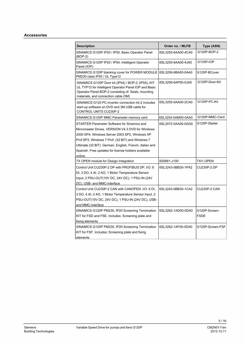
Accessories
Description Order no. / MLFB Type (ASN)
SINAMICS G120P IP20 / IP55, Basic Operator Panel
(BOP-2) 6SL3255-6AA00-4CA0 G120P-BOP-2
SINAMICS G120P IP20 / IP54, Intelligent Operator
Panel (IOP) 6SL3255-6AA00-4JA0 G120P-IOP
SINAMICS G120P blanking cover for POWER MODULE
PM230 class IP55 / UL Type12
6SL3256-6BA00-0AA0 G120P-BCover
SINAMICS G120P Door kit (IP54) / BOP-2 (IP55), KIT
UL TYP12 for Intelligent Operator Panel IOP and Basic
Operator Panel BOP-2 consisting of: Seals, mounting
materials, and connection cable (5M)
6SL3256-6AP00-0JA0 G120P-Door-Kit
SINAMICS G120 PC-inverter connection kit-2 includes
start-up software on DVD and 3M USB cable for
CONTROL UNITS CU230P-2
6SL3255-0AA00-2CA0 G120P-PC-Kit
SINAMICS G120P MMC Parameter memory card 6SL3254-0AM00-0AA0 G120P-MMC-Card
STARTER Parameter Software for Sinamics and
Micromaster Drives. VERSION V4.3 DVD for Windows
2000 SP4, Windows Server 2003 SP2, Windows XP
Prof SP3, Windows 7 Prof. (32 BIT) and Windows 7
Ultimate (32 BIT). German, English, French, Italian and
Spanish. Free updates for license holders available
online.
6SL3072-0AA00-0AG0 G120P-Starter
TX OPEN module for Desigo Integration S55661-J100 TXI1.OPEN
Control Unit CU230P-2 DP with PROFIBUS DP. I/O: 6
DI, 3 DO, 4 AI, 2 AO, 1 Motor Temperature Sensor
Input, 2 PSU-OUT(10V DC, 24V DC), 1 PSU-IN (24V
DC), USB- and MMC-interface
6SL3243-0BB30-1PA2 CU230P-2 DP
Control Unit CU230P-2 CAN with CANOPEN. I/O: 6 DI,
3 DO, 4 AI, 2 AO, 1 Motor Temperature Sensor Input, 2
PSU-OUT(10V DC, 24V DC), 1 PSU-IN (24V DC), USB-
and MMC-interface
6SL3243-0BB30-1CA2 CU230P-2 CAN
SINAMICS G120P PM230, IP20 Screening Termination
KIT for FSD and FSE. Includes: Screening plate and
fixing elements
6SL3262-1AD00-0DA0 G120P-Screen-
FSDE
SINAMICS G120P PM230, IP20 Screening Termination
KIT for FSF. Includes: Screening plate and fixing
elements
6SL3262-1AF00-0DA0 G120P-Screen-FSF
5 / 16
Siemens Variable Speed Drive for pumps and fans G120P CM2N5111en
Building Technologies 2012-12-11
7/25/2019 File-1361381461 wer w
http://slidepdf.com/reader/full/file-1361381461-wer-w 6/16
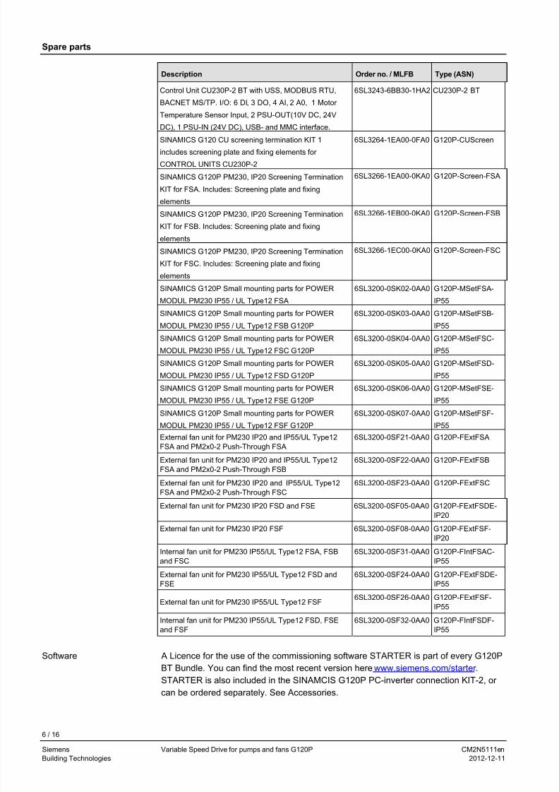
Spare parts
Description Order no. / MLFB Type (ASN)
Control Unit CU230P-2 BT with USS, MODBUS RTU,
BACNET MS/TP. I/O: 6 DI, 3 DO, 4 AI, 2 A0, 1 Motor
Temperature Sensor Input, 2 PSU-OUT(10V DC, 24V
DC), 1 PSU-IN (24V DC), USB- and MMC interface.
6SL3243-6BB30-1HA2 CU230P-2 BT
SINAMICS G120 CU screening termination KIT 1
includes screening plate and fixing elements for
CONTROL UNITS CU230P-2
6SL3264-1EA00-0FA0 G120P-CUScreen
SINAMICS G120P PM230, IP20 Screening Termination
KIT for FSA. Includes: Screening plate and fixing
elements
6SL3266-1EA00-0KA0 G120P-Screen-FSA
SINAMICS G120P PM230, IP20 Screening Termination
KIT for FSB. Includes: Screening plate and fixing
elements
6SL3266-1EB00-0KA0 G120P-Screen-FSB
SINAMICS G120P PM230, IP20 Screening Termination
KIT for FSC. Includes: Screening plate and fixing
elements
6SL3266-1EC00-0KA0 G120P-Screen-FSC
SINAMICS G120P Small mounting parts for POWER
MODUL PM230 IP55 / UL Type12 FSA
6SL3200-0SK02-0AA0 G120P-MSetFSA-
IP55
SINAMICS G120P Small mounting parts for POWER
MODUL PM230 IP55 / UL Type12 FSB G120P
6SL3200-0SK03-0AA0 G120P-MSetFSB-
IP55
SINAMICS G120P Small mounting parts for POWER
MODUL PM230 IP55 / UL Type12 FSC G120P
6SL3200-0SK04-0AA0 G120P-MSetFSC-
IP55
SINAMICS G120P Small mounting parts for POWER
MODUL PM230 IP55 / UL Type12 FSD G120P
6SL3200-0SK05-0AA0 G120P-MSetFSD-
IP55
SINAMICS G120P Small mounting parts for POWER
MODUL PM230 IP55 / UL Type12 FSE G120P
6SL3200-0SK06-0AA0 G120P-MSetFSE-
IP55
SINAMICS G120P Small mounting parts for POWERMODUL PM230 IP55 / UL Type12 FSF G120P
6SL3200-0SK07-0AA0 G120P-MSetFSF-IP55
External fan unit for PM230 IP20 and IP55/UL Type12
FSA and PM2x0-2 Push-Through FSA
6SL3200-0SF21-0AA0 G120P-FExtFSA
External fan unit for PM230 IP20 and IP55/UL Type12
FSA and PM2x0-2 Push-Through FSB
6SL3200-0SF22-0AA0 G120P-FExtFSB
External fan unit for PM230 IP20 and IP55/UL Type12
FSA and PM2x0-2 Push-Through FSC
6SL3200-0SF23-0AA0 G120P-FExtFSC
External fan unit for PM230 IP20 FSD and FSE 6SL3200-0SF05-0AA0 G120P-FExtFSDE-
IP20
External fan unit for PM230 IP20 FSF 6SL3200-0SF08-0AA0 G120P-FExtFSF-
IP20
Internal fan unit for PM230 IP55/UL Type12 FSA, FSBand FSC 6SL3200-0SF31-0AA0 G120P-FIntFSAC-IP55
External fan unit for PM230 IP55/UL Type12 FSD and
FSE
6SL3200-0SF24-0AA0 G120P-FExtFSDE-
IP55
External fan unit for PM230 IP55/UL Type12 FSF6SL3200-0SF26-0AA0 G120P-FExtFSF-
IP55
Internal fan unit for PM230 IP55/UL Type12 FSD, FSE
and FSF
6SL3200-0SF32-0AA0 G120P-FIntFSDF-
IP55
Software A Licence for the use of the commissioning software STARTER is part of every G120P
BT Bundle. You can find the most recent version here www.siemens.com/starter .
STARTER is also included in the SINAMCIS G120P PC-inverter connection KIT-2, or
can be ordered separately. See Accessories.
6 / 16
Siemens Variable Speed Drive for pumps and fans G120P CM2N5111en
Building Technologies 2012-12-11
7/25/2019 File-1361381461 wer w
http://slidepdf.com/reader/full/file-1361381461-wer-w 7/16
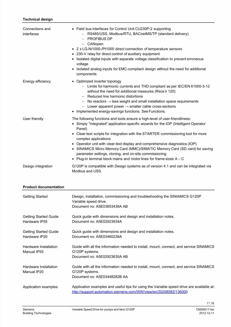
Technical design
• Field bus interfaces for Control Unit CU230P-2 supportingConnections and
interfaces − RS485/USS, Modbus/RTU, BACnetMS/TP (standard delivery)
− PROFIBUS DP
− CANopen
• 2 x LG-Ni1000-/Pt1000 direct connection of temperature sensors
• 230-V relay for direct control of auxiliary equipment
• Isolated digital inputs with separate voltage classification to prevent erroneous
voltage
• Isolated analog inputs for EMC-compliant design without the need for additional
components
• Optimized inverter topologyEnergy efficiency
− Limits for harmonic currents and THD compliant as per IEC/EN 61000-3-12
without the need for additional measures (Rsce ≥ 120)
− Reduced line harmonic distortions
− No reactors → less weight and small installation space requirements
− Lower apparent power → smaller cable cross-sections
• Implemented energy-savings functions. See Functions.
The following functions and tools ensure a high-level of user-friendliness:User friendly
• Simply "integrated" application-specific wizards for the IOP (Intelligent Operator
Panel)
• Clear-text scripts for integration with the STARTER commissioning tool for more
complex applications
• Operator unit with clear-text display and comprehensive diagnostics (IOP)
• SINAMICS Micro Memory Card (MMC)/SIMATIC Memory Card (SD card) for saving
parameter settings, cloning, and on-site commissioning
• Plug-in terminal block mains and motor lines for frame sizes A – C
G120P is compatible with Desigo systems as of version 4.1 and can be integrated via
Modbus and USS.
Desigo integration
Product documentation
Design, installation, commissioning and troubleshooting the SINIAMICS G120P
Variable speed drive.
Getting Started
Document no: A5E03653438A AB
Quick guide with dimensions and design and installation notes.Getting Started Guide
Hardware IP55 Document no: A5E02923634A
Quick guide with dimensions and design and installation notes.Getting Started Guide
Hardware IP20 Document no: A5E03460238A
Guide with all the information needed to install, mount, connect, and service SINAMICS
G120P systems.
Hardware Installation
Manual IP55
Document no: A5E02923635A AB
Guide with all the information needed to install, mount, connect, and service SINAMICS
G120P systems.
Hardware Installation
Manual IP20
Document no: A5E03448282B AA
Application examples and useful tips for using the Variable speed drive are available at:http://support.automation.siemens.com/WW/view/en/20208582/136000
Application examples
7 / 16
Siemens Variable Speed Drive for pumps and fans G120P CM2N5111en
Building Technologies 2012-12-11
7/25/2019 File-1361381461 wer w
http://slidepdf.com/reader/full/file-1361381461-wer-w 8/16
Detailed information and support tools for the Variable speed drive are available at:General product
information http://www.siemens.com/g120p
Guide for installers, commissioners, and operators on control unit CU230P-2Operating Instructions
Control-Unit Document no: A5E02430659B AD
Guide with list information including parameters and error codes.Parameter manual
control unit Document no: A5E02297932B AE
Information on commissioning and integrating into Desigo systems including parameter
settings
Desigo
Document no: CM110576
SINAMICS BACnet Protocol Implementation Conformance StatementPICS
Document no: CM2Y5111
Data sheet with general information on the supplemental system components IOP,
BOP-2, and the blanking cover
Data sheet: system
components
Document no.: CM1N5116en
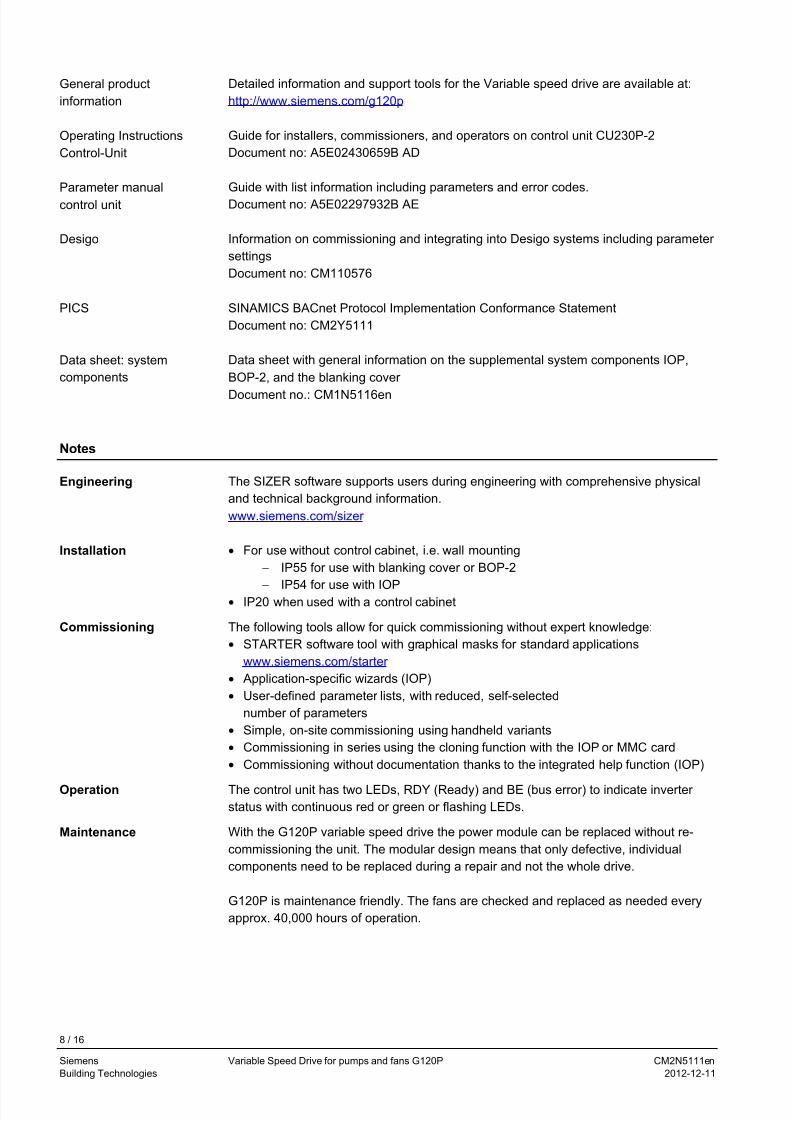
Notes
The SIZER software supports users during engineering with comprehensive physical
and technical background information.
Engineering
www.siemens.com/sizer
• For use without control cabinet, i.e. wall mountingInstallation
− IP55 for use with blanking cover or BOP-2
−
IP54 for use with IOP• IP20 when used with a control cabinet
Commissioning The following tools allow for quick commissioning without expert knowledge:
• STARTER software tool with graphical masks for standard applications
www.siemens.com/starter
• Application-specific wizards (IOP)
• User-defined parameter lists, with reduced, self-selected
number of parameters
• Simple, on-site commissioning using handheld variants
• Commissioning in series using the cloning function with the IOP or MMC card
• Commissioning without documentation thanks to the integrated help function (IOP)
Operation The control unit has two LEDs, RDY (Ready) and BE (bus error) to indicate inverter
status with continuous red or green or flashing LEDs.
With the G120P variable speed drive the power module can be replaced without re-
commissioning the unit. The modular design means that only defective, individual
components need to be replaced during a repair and not the whole drive.
Maintenance
G120P is maintenance friendly. The fans are checked and replaced as needed every
approx. 40,000 hours of operation.
8 / 16
Siemens Variable Speed Drive for pumps and fans G120P CM2N5111en
Building Technologies 2012-12-11
7/25/2019 File-1361381461 wer w
http://slidepdf.com/reader/full/file-1361381461-wer-w 9/16
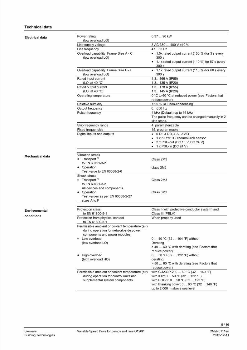
Technical data
Power rating
(low overload LO) 0.37 ... 90 kW
Line supply voltage 3 AC 380 … 480 V ±10 % Line frequency 47…63 Hz Overload capability Frame Size A - C
(low overload LO) • 1.5x rated output current (150 %) for 3 s every
300 s
• 1.1x rated output current (110 %) for 57 s every300 s
Overload capability Frame Size D - F
(low overload LO)
• 1.1x rated output current (110 %) for 60 s every
300 s
Rated input current
(LO: at 40 °C) 1.3…166 A (IP55)
1.3…135 A (IP20) Rated output current
(LO: at 40 °C) 1.3…178 A (IP55)
1.3…145 A (IP20) Operating temperature 0 °C to 60 °C at reduced power (see Factors that
reduce power ) Relative humidity < 95 % RH, non-condensing Output frequency 0…650 Hz Pulse frequency 4 kHz (Default) up to 16 kHz
The pulse frequency can be changed manually in 2
kHz steps- Skip frequency range 4, parameterizable Fixed frequencies 15, programmable Digital inputs and outputs • 6 DI, 3 DO, 4 AI, 2 AO
• 1 x KTY/PTC/ThermoClick sensor
• 2 x PSU-out (DC 10 V, DC 24 V)
• 1 x PSU-in (DC 24 V)
Vibration stress
• Transport1)
to EN 60721-3-2
• Operation
Test value to EN 60068-2-6
Class 2M3
class 3M2
Shock stress
• Transport1)
to EN 60721-3-2 All devices and components
• Operation
Test values as per EN 60068-2-27
sizes A to F
Class 2M3
Class 3M2
Protection class
to EN 61800-5-1 Class I (with protective conductor system) and
Class III (PELV) Protection from physical contact
to EN 61800-5-1 When properly used
Permissible ambient or coolant temperature (air)
during operation for network-side power
components and power modules
• Low overload
(low overload LO)
• High overload
(high overload HO)
0 … 40 °C (32 … 104 °F) without
Derating
> 40 … 60 °C with derating (see Factors that
reduce power )
0 … 50 °C (32 … 122 °F) without
derating
> 50 … 60 °C with derating (see Factors that
reduce power )
Permissible ambient or coolant temperature (air)
during operation for control units and
supplemental system components
with CU230P-2: 0 ... 60 °C (32 ... 140 °F) with IOP: 0 ... 50 °C (32 ... 122 °F)
with BOP-2: 0 ... 50 °C (32 ... 122 °F)
with Blanking cover: 0 ... 60 °C (32 ... 140 °F)
up to 2 000 m above sea level
Electrical data
Mechanical data
Environmental
conditions
9 / 16
Siemens Variable Speed Drive for pumps and fans G120P CM2N5111en
Building Technologies 2012-12-11
7/25/2019 File-1361381461 wer w
http://slidepdf.com/reader/full/file-1361381461-wer-w 10/16
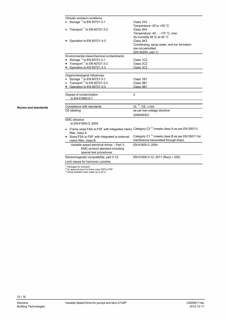
Climatic ambient conditions:
• Storage1)
to EN 60721-3-1
• Transport1)
to EN 60721-3-2
• Operation to EN 60721-3-3
Class 1K3
Temperature -25 to +55 °C.
Class 2K4
Temperature -40 … +70 °C, max.
Air humidity 95 % at 40 °C
Class 3K3
Condensing, spray water, and ice formation
are not permitted
(EN 60204, part 1)
Environmental class/chemical contaminants:• Storage
1) to EN 60721-3-1
• Transport1)
to EN 60721-3-2
• Operation to EN 60721-3-3
Class 1C2
Class 2C2
Class 3C2
Organic/biological influences:
• Storage1)
to EN 60721-3-1
• Transport1)
to EN 60721-3-2
• Operation to EN 60721-3-3
Class 1B1 Class 2B1 Class 3B1
Degree of contamination
to EN 61800-5-1 2
Compliance with standards UL2)
, CE, c-tick
CE labeling as per low-voltage directive
2006/95/EC
EMC directive
to EN 61800-3: 2004
• Frame sizes FSA to FSF with integrated mains
filter, class A
• Sizes FSA to FSF with integrated or external
mains filter, class B
Category C23)
(meets class A as per EN 55011)
Category C13)
(meets class B as per EN 55011 for
interference transmitted through lines)
Variable speed electrical drives – Part 3:
EMC product standard including
special test procedures
EN 61800-3: 2004
Electromagnetic compatibility, part 3-12:
Limit values for harmonic currents
EN 61000-3-12: 2011 (Rsce > 250)
1) Packages for transport
Norms and standards
2) UL approval soon for frame sizes FSD to FSF3)
Using shielded motor cable up to 25 m
10 / 16
Siemens Variable Speed Drive for pumps and fans G120P CM2N5111en
Building Technologies 2012-12-11
7/25/2019 File-1361381461 wer w
http://slidepdf.com/reader/full/file-1361381461-wer-w 11/16
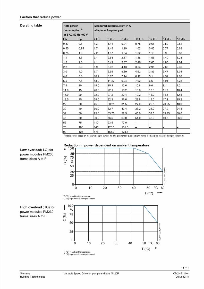
Factors that reduce power
Rate power
consumption1)
at 3 AC 50 Hz 400 V
Measured output current in A
at a pulse frequency of
kW hp 4 kHz 6 kHz 8 kHz 10 kHz 12 kHz 14 kHz 16 kHz
0.37 0.5 1.3 1.11 0.91 0.78 0.65 0.59 0.52
0.55 0.75 1.7 1.45 1.19 1.02 0.85 0.77 0.68
0.75 1.0 2.2 1.87 1.54 1.32 1.10 0.99 0.88
1.1 1.5 3.1 2.64 2.17 1.86 1.55 1.40 1.24
1.5 2.0 4.1 3.49 2.87 2.46 2.05 1.85 1.64
2.2 3.0 5.9 5.02 4.13 3.54 2.95 2.66 2.36
3.0 4.0 7.7 6.55 5.39 4.62 3.85 3.47 3.08
4.0 5.0 10.2 8.67 7.14 6.12 5.1 4.59 4.08
5.5 7.5 13.2 11.22 9.24 7.92 6.6 5.94 5.28
7.5 10 18.0 15.3 12.6 10.8 9.0 8.1 7.2
11.0 15 26.0 22.1 18.2 15.6 13.0 11.7 10.4
15.0 20 32.0 27.2 22.4 19.2 16.0 14.4 12.8
18.5 25 38.0 32.3 26.6 22.8 19.0 17.1 15.2
22 30 45.0 38.25 31.5 27.0 22.5 20.25 18.0
30 40 60.0 52.7 43.4 37.2 31.0 27.9 24.8
37 50 75.0 63.75 52.5 45.0 37.5 33.75 30.0
45 60 90.0 76.5 63.0 54.0 45.0 40.5 36.0
55 75 110 93.5 77.0 – – – –
75 100 145 123.3 101.5 – – – –
90 125 178 151.3 124.6
Derating table
1) Rated power based on measured output current /N. The play for low overload (LO) forms the basis for measured output current /N.
Reduction in power dependent on ambient temperature
100
2535
0
50
%
7585
60°C504010 30200 G_
D 0 1 1_
D E_
0 0 3 0 9
C ( % )
T (°C)
Low overload( LO) for
power modules PM230
frame sizes A to F
T (°C) = ambient temperature
C (%) = permissible output current
10 0
25
0
50
%
75
60°C504010 30200
G_
D 0 1 1_
D E_
0 0 3 0 8
T (°C)
High overload (HO) for
power modules PM230
frame sizes A to F
T (°C) = ambient temperature
C (%) = permissible output current
11 / 16
Siemens Variable Speed Drive for pumps and fans G120P CM2N5111en
Building Technologies 2012-12-11
7/25/2019 File-1361381461 wer w
http://slidepdf.com/reader/full/file-1361381461-wer-w 12/16
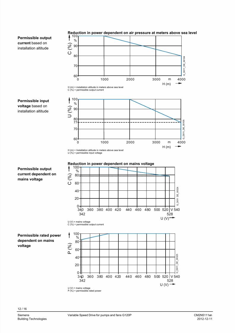
Reduction in power dependent on air pressure at meters above sea level
80
100
%
0 1000 m
70
90
60
H (m)
G_
D 0 1 1_
D E_
0 0 1 0
4
30002000 4000
C ( % )
Permissible output
current based on
installation altitude
H (m) = installation altitude in meters above sea level
C (%) = permissible output current
80
100
%
m
77
70
90
60 G_
D 0 1 1_
D E_
0 0 1 0 5 U
( % )
H (m)
0 1000 30002000 4000
Permissible input
voltage based on
installation altitude
H (m) = Installation altitude in meters above sea level U (%) = permissible input voltage
Reduction in power dependent on mains voltage
20
40
60
80
100%
0340
342 528
360 380 400 420 440 460 480 500 V520 540
U (V)
C ( % )
G_
D 0 1 1_
D E_
0 0 3 2 4
Permissible output
current dependent onmains voltage
U (V) = mains voltageC (%) = permissible output current
20
40
60
80
100%
0
342 528
G_
D 0 1 1_
D E_
0 0 3 2 5
340 360 380 400 420 440 460 480 500 V520 540
P ( % )
U (V)
Permissible rated power
dependent on mains
voltage
U (V) = mains voltage
P (%) = permissible rated power
12 / 16
Siemens Variable Speed Drive for pumps and fans G120P CM2N5111en
Building Technologies 2012-12-11
7/25/2019 File-1361381461 wer w
http://slidepdf.com/reader/full/file-1361381461-wer-w 13/16
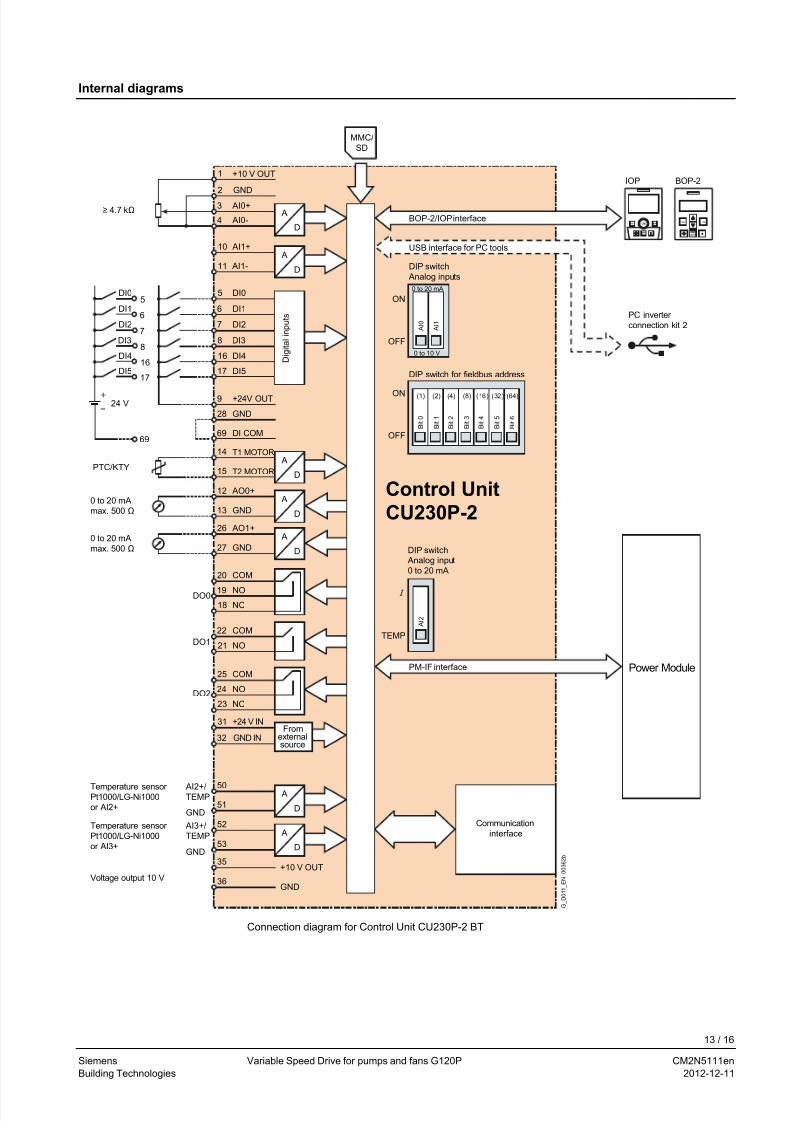
Internal diagrams
ESC OK
(1)
B i t 1
(64)(16) (32)(2) (4) (8)
B i t 0
B i t 3
B i t 2
B i t 5
B i t 6
B i t 4
G_
D 0 1 1_
E N_
0 0 3 6 2 b
Voltage output 10 V
Temperature sensor Pt1000/LG-Ni1000
or AI2+
Temperature sensor
Pt1000/LG-Ni1000
or AI3+
PM-IF interface
0 to 10 V
0 to 20 mA
PC inverter
connection kit 2
OFF
ON
OFF
ON
0 to 20 mA
max. 500 Ω
0 to 20 mA
max. 500 Ω
≥ 4.7 kΩBOP-2/IOP interface
USB interface for PC tools
D i g i t a l i n p u t s
Fromexternalsource
DIP switch
Analog inputs
DIP switch Analog input
0 to 20 mA
DIP switch for fieldbus address
Communication
interface
69
17
16
8
7
6
5
+
24 V
DI5
DI4
DI3
DI2
DI1
DI0
MMC/
SD
PTC/KTY
Power Module
A I 1
A I 0
DO0
DO2
DO1
GND27
AO1+26
D
A
D
A
GND IN32
+24 V IN31
GND28
NO21
COM22
NO24
NC23
COM25
NO19
NC18
COM20
GND13
AO0+12
15
14
69
+24V OUT
T1 MOTOR
T2 MOTOR
9
DI517
DI416
DI38
DI27
DI16
DI05
AI1-11
AI1+10
AI0-4
AI0+3
2
1
GND
+10 V OUT
D
A
D
A
D
A
GND36
+10 V OUT35
53
52
51
50
D
A
D
A
GND
GND
AI2+/TEMP
AI3+/
TEMP
Control Unit
CU230P-2
DI COM
A I 2
BOP-2IOP
TEMP
Connection diagram for Control Unit CU230P-2 BT
13 / 16
Siemens Variable Speed Drive for pumps and fans G120P CM2N5111en
Building Technologies 2012-12-11
7/25/2019 File-1361381461 wer w
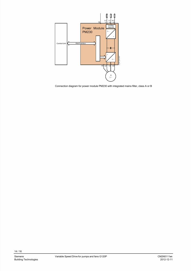
http://slidepdf.com/reader/full/file-1361381461-wer-w 14/16
Line filter class A/B
G_
D 0 1 1_
E N_
0 0 3 1 7
PM-IF Interface
PEU1/L1
V1/L2
W1/L3
~3
=
Power Module
PM230
Control Unit
=
~3
W2V2U2PE
~3
M
Connection diagram for power module PM230 with integrated mains filter, class A or B
14 / 16
Siemens Variable Speed Drive for pumps and fans G120P CM2N5111en
Building Technologies 2012-12-11
7/25/2019 File-1361381461 wer w
http://slidepdf.com/reader/full/file-1361381461-wer-w 15/16
Dimensions
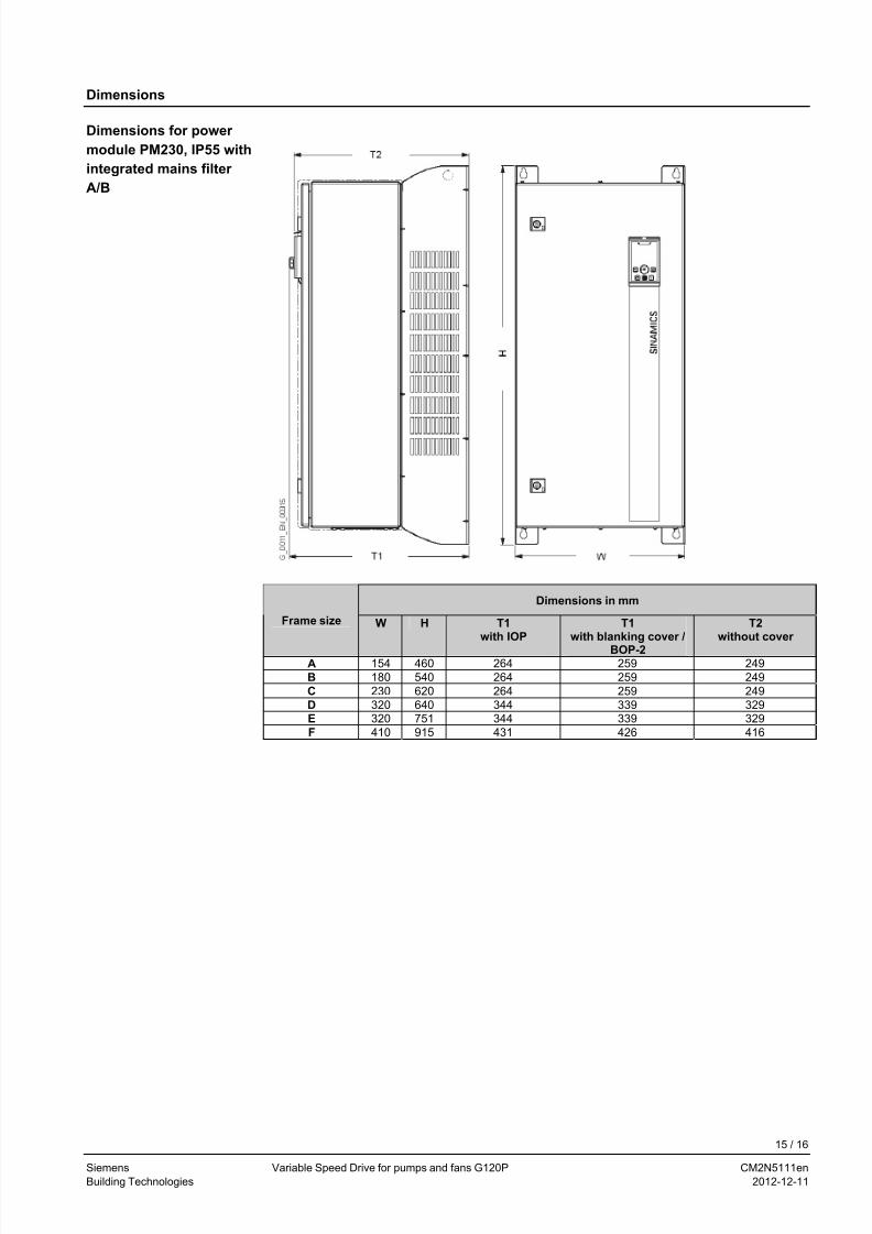
Dimensions for power
module PM230, IP55 with
integrated mains filter
A/B
Dimensions in mm
Frame size W H T1with IOP
T1with blanking cover /
BOP-2
T2without cover
A 154 460 264 259 249
B 180 540 264 259 249
C 230 620 264 259 249
D 320 640 344 339 329E 320 751 344 339 329
F 410 915 431 426 416
15 / 16
Siemens Variable Speed Drive for pumps and fans G120P CM2N5111en
Building Technologies 2012-12-11
7/25/2019 File-1361381461 wer w
http://slidepdf.com/reader/full/file-1361381461-wer-w 16/16
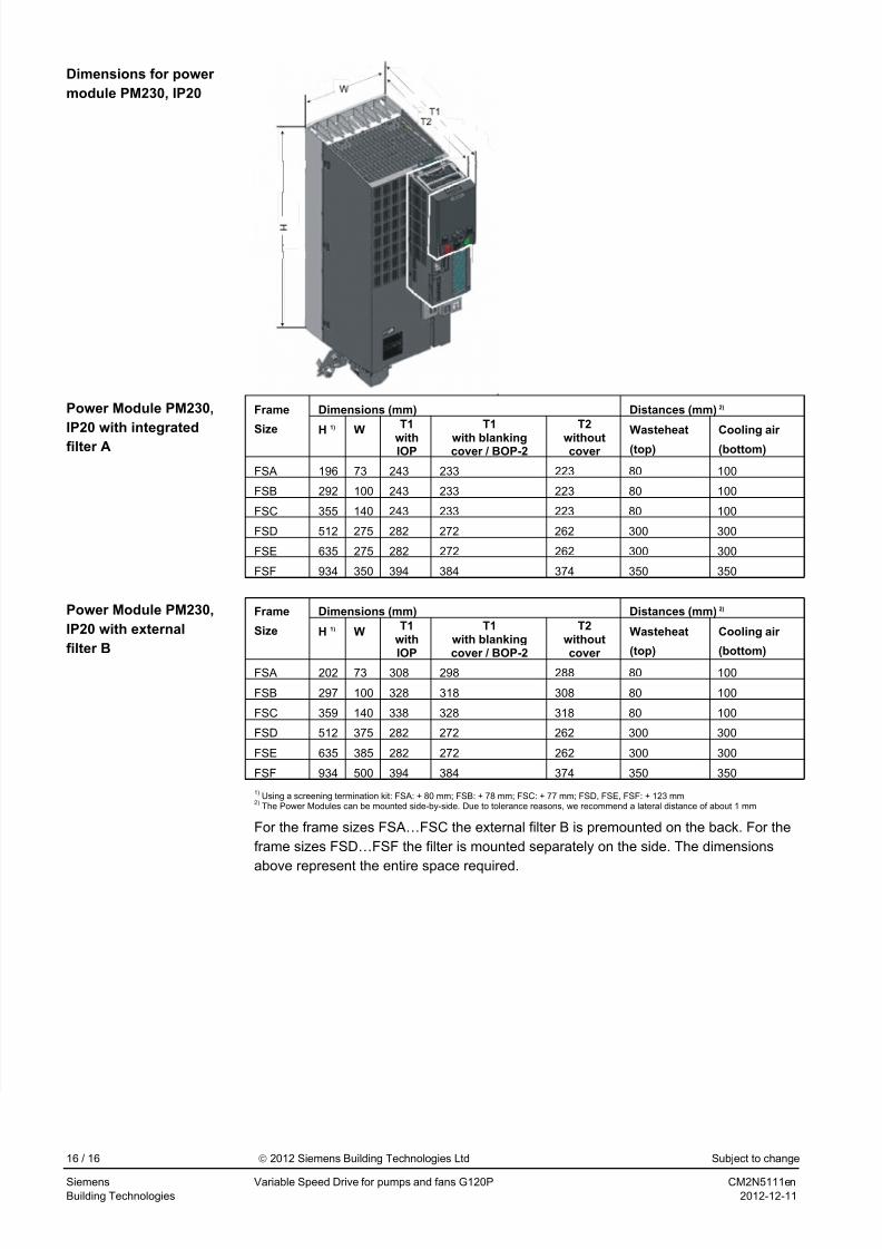
Dimensions for power
module PM230, IP20
Dimensions (mm) Distances (mm) 2) Frame
Size H 1) WT1
withIOP
T1
with blankingcover / BOP-2
T2
withoutcover
Wasteheat
(top)
Cooling air
(bottom)
FSA 196 73 243 233 223 80 100
FSB 292 100 243 233 223 80 100
FSC 355 140 243 233 223 80 100
FSD 512 275 282 272 262 300 300
FSE 635 275 282 272 262 300 300
FSF 934 350 394 384 374 350 350
Power Module PM230,
IP20 with integrated
filter A
Dimensions (mm) Distances (mm) 2) Frame
Size H 1) WT1
with
IOP
T1with blanking
cover / BOP-2
T2without
cover
Wasteheat
(top)
Cooling air
(bottom)FSA 202 73 308 298 288 80 100
FSB 297 100 328 318 308 80 100
FSC 359 140 338 328 318 80 100
FSD 512 375 282 272 262 300 300
FSE 635 385 282 272 262 300 300
FSF 934 500 394 384 374 350 350
Power Module PM230,
IP20 with external
filter B
1) Using a screening termination kit: FSA: + 80 mm; FSB: + 78 mm; FSC: + 77 mm; FSD, FSE, FSF: + 123 mm
2) The Power Modules can be mounted side-by-side. Due to tolerance reasons, we recommend a lateral distance of about 1 mm
For the frame sizes FSA…FSC the external filter B is premounted on the back. For the
frame sizes FSD…FSF the filter is mounted separately on the side. The dimensions
above represent the entire space required.
16 / 16
Siemens Variable Speed Drive for pumps and fans G120P CM2N5111en
2012 Siemens Building Technologies Ltd Subject to change


![HOLZ FENSTER HOLZ ALU FENSTER - hsf.sk file- 22 - HOLZ FENSTER HOLZ ALU FENSTER Verglasung U f-Wert** Ψ g-Wert U g-Wert [W/(m2K)] U w-Wert [W/(m2K)] System [W/(m2K)] HA 086 1,03 Superspacer](https://img.pdfslide.org/doc/110x75/5cffe55388c99363028b54b2/holz-fenster-holz-alu-fenster-hsfsk-22-holz-fenster-holz-alu-fenster-verglasung.jpg)


![SNB160(W) | SNB200(W) | SUB300(W) | SBB200(W ...documents.buderus.com/download/pdf/file/6720808563.pdf[de] Installations- und Bedienungsanleitung 2 [it] Istruzioni per l'installazione](https://img.pdfslide.org/doc/110x75/5b19054c7f8b9a3c258c4b0d/snb160w-snb200w-sub300w-sbb200w-de-installations-und-bedienungsanleitung.jpg)