Embed Size (px)
Citation preview
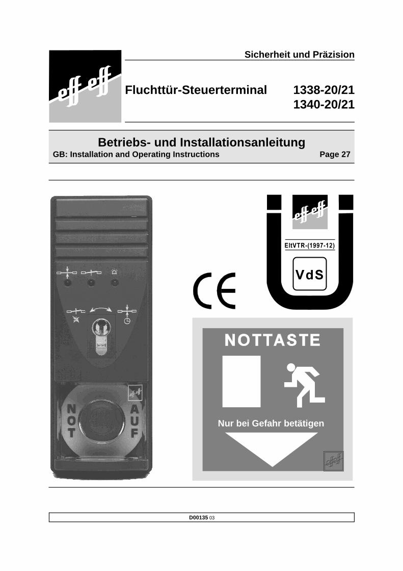
Nur bei Gefahr betätigen
D00135 03
Betriebs- und InstallationsanleitungGB: Installation and Operating Instructions Page 27
Sicherheit und Präzision
Fluchttür-Steuerterminal 1338-20/211340-20/21

Inhalt
1 Funktion und Bedienung . . . . . . . . . . . . . . . . . . . . . . . . . . . . . . . . . . . . . . . . . . . . . 3
1.1 Allgemeine Beschreibung . . . . . . . . . . . . . . . . . . . . . . . . . . . . . . . . . . . . . . . . . . . . . . . . . . . . 41.1.1 Modellbeschreibung . . . . . . . . . . . . . . . . . . . . . . . . . . . . . . . . . . . . . . . . . . . . . . . . . . 4
1.2 Funktionsbeschreibung . . . . . . . . . . . . . . . . . . . . . . . . . . . . . . . . . . . . . . . . . . . . . . . . . . . . . . 51.2.1 Funktion beim Einschalten oder Netzwiederkehr . . . . . . . . . . . . . . . . . . . . . . . . . . . 51.2.2 Kurzzeitfreigabe . . . . . . . . . . . . . . . . . . . . . . . . . . . . . . . . . . . . . . . . . . . . . . . . . . . . . 51.2.3 Dauerentriegelung . . . . . . . . . . . . . . . . . . . . . . . . . . . . . . . . . . . . . . . . . . . . . . . . . . . 61.2.4 Verriegelung . . . . . . . . . . . . . . . . . . . . . . . . . . . . . . . . . . . . . . . . . . . . . . . . . . . . . . . 6
1.3 Alarm . . . . . . . . . . . . . . . . . . . . . . . . . . . . . . . . . . . . . . . . . . . . . . . . . . . . . . . . . . . . . . . . . . . . 61.3.1 Gefahrenalarm . . . . . . . . . . . . . . . . . . . . . . . . . . . . . . . . . . . . . . . . . . . . . . . . . . . . . . 71.3.2 Anschluß und Alarm durch eine Brandmeldeanlage (Klemme 13/14) . . . . . . . . . . . . 71.3.3 Sabotagealarm . . . . . . . . . . . . . . . . . . . . . . . . . . . . . . . . . . . . . . . . . . . . . . . . . . . . . 71.3.4 Alarm durch Türaufbruch . . . . . . . . . . . . . . . . . . . . . . . . . . . . . . . . . . . . . . . . . . . . . . 71.3.5 Behandlung von Mehrfachalarmen . . . . . . . . . . . . . . . . . . . . . . . . . . . . . . . . . . . . . . 71.3.6 Überwachung der Türöffnungszeit . . . . . . . . . . . . . . . . . . . . . . . . . . . . . . . . . . . . . . . 8
1.4 Übersicht über Bedien- und Anzeigeelemente . . . . . . . . . . . . . . . . . . . . . . . . . . . . . . . . . . . . 91.5 Ermittlung einer Alarmbedingung . . . . . . . . . . . . . . . . . . . . . . . . . . . . . . . . . . . . . . . . . . . . . . 101.6 Einstellmöglichkeiten am Fluchttür-Steuerterminal . . . . . . . . . . . . . . . . . . . . . . . . . . . . . . . . 11
1.6.1 Steckbrücke JP-1 . . . . . . . . . . . . . . . . . . . . . . . . . . . . . . . . . . . . . . . . . . . . . . . . . . 111.6.2 Steckbrücke JP-2 . . . . . . . . . . . . . . . . . . . . . . . . . . . . . . . . . . . . . . . . . . . . . . . . . . 111.6.3 Funktionsschalter S 4.1 . . . . . . . . . . . . . . . . . . . . . . . . . . . . . . . . . . . . . . . . . . . . . 111.6.4 Funktionsschalter S 4.2 . . . . . . . . . . . . . . . . . . . . . . . . . . . . . . . . . . . . . . . . . . . . . . 111.6.5 Funktionsschalter S 4.3 . . . . . . . . . . . . . . . . . . . . . . . . . . . . . . . . . . . . . . . . . . . . . 111.6.6 Funktionsschalter S 4.4 . . . . . . . . . . . . . . . . . . . . . . . . . . . . . . . . . . . . . . . . . . . . . . 111.6.7 Funktionsschalter S 4.5 . . . . . . . . . . . . . . . . . . . . . . . . . . . . . . . . . . . . . . . . . . . . . . 111.6.8 Vorwahlschalter S1: Freigabezeit . . . . . . . . . . . . . . . . . . . . . . . . . . . . . . . . . . . . . . 121.6.9 Vorwahlschalter S2: Voralarmzeit . . . . . . . . . . . . . . . . . . . . . . . . . . . . . . . . . . . . . . 121.6.10 Vorwahlschalter S3: Alarmzeit . . . . . . . . . . . . . . . . . . . . . . . . . . . . . . . . . . . . . . . . . 12
1.7 Busbetrieb . . . . . . . . . . . . . . . . . . . . . . . . . . . . . . . . . . . . . . . . . . . . . . . . . . . . . . . . . . . . . . . 12
2 Montage und Installation . . . . . . . . . . . . . . . . . . . . . . . . . . . . . . . . . . . . . . . . . . . . 13
2.1 Hinweise zur Montage . . . . . . . . . . . . . . . . . . . . . . . . . . . . . . . . . . . . . . . . . . . . . . . . . . . . . . 142.2 Leitungsauswahl . . . . . . . . . . . . . . . . . . . . . . . . . . . . . . . . . . . . . . . . . . . . . . . . . . . . . . . . . . 152.3 Servicehinweise . . . . . . . . . . . . . . . . . . . . . . . . . . . . . . . . . . . . . . . . . . . . . . . . . . . . . . . . . . . 15
2.3.1 Öffnen des Gehäuses, AP-Montage, UP-Montage . . . . . . . . . . . . . . . . . . . . . . . . . 152.3.2 Auswechseln der Multi- LED oder des Profilhalbzylinders . . . . . . . . . . . . . . . . . . . . 16
2.4 Busbetrieb . . . . . . . . . . . . . . . . . . . . . . . . . . . . . . . . . . . . . . . . . . . . . . . . . . . . . . . . . . . . . . . 172.4.1 Busanschluß . . . . . . . . . . . . . . . . . . . . . . . . . . . . . . . . . . . . . . . . . . . . . . . . . . . . . . 172.4.2 Einstellung der Teilnehmeradresse am Fluchttürterminal . . . . . . . . . . . . . . . . . . . 17
2.5 Technische Daten und Anschlußplan für 1338-20/21 . . . . . . . . . . . . . . . . . . . . . . . . . . . . . . 182.5.1 Elektrische Daten . . . . . . . . . . . . . . . . . . . . . . . . . . . . . . . . . . . . . . . . . . . . . . . . . . 182.5.2 Technische Daten . . . . . . . . . . . . . . . . . . . . . . . . . . . . . . . . . . . . . . . . . . . . . . . . . . 182.5.3 Anschließbare Verriegelungsteile . . . . . . . . . . . . . . . . . . . . . . . . . . . . . . . . . . . . . . 182.5.4 Anschlußplan . . . . . . . . . . . . . . . . . . . . . . . . . . . . . . . . . . . . . . . . . . . . . . . . . . . . . . 19
2.6 Technische Daten und Anschlußplan für 1340-20/21 Version 12V . . . . . . . . . . . . . . . . . . . . 202.6.1 Elektrische Daten . . . . . . . . . . . . . . . . . . . . . . . . . . . . . . . . . . . . . . . . . . . . . . . . . . 202.6.2 Technische Daten . . . . . . . . . . . . . . . . . . . . . . . . . . . . . . . . . . . . . . . . . . . . . . . . . . 202.6.3 Anschließbare Verriegelungsteile . . . . . . . . . . . . . . . . . . . . . . . . . . . . . . . . . . . . . . 202.6.4 Anschlußplan . . . . . . . . . . . . . . . . . . . . . . . . . . . . . . . . . . . . . . . . . . . . . . . . . . . . . . 21
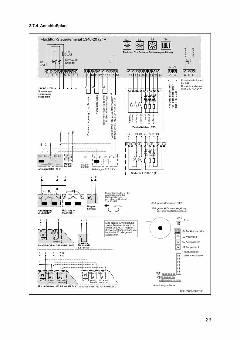
2.7 Technische Daten und Anschlußplan für 1340-20/21 Version 24 V . . . . . . . . . . . . . . . . . . . 222.7.1 Elektrische Daten . . . . . . . . . . . . . . . . . . . . . . . . . . . . . . . . . . . . . . . . . . . . . . . . . . 222.7.2 Technische Daten . . . . . . . . . . . . . . . . . . . . . . . . . . . . . . . . . . . . . . . . . . . . . . . . . . 222.7.3 Anschließbare Verriegelungsteile . . . . . . . . . . . . . . . . . . . . . . . . . . . . . . . . . . . . . . 222.7.4 Anschlußplan . . . . . . . . . . . . . . . . . . . . . . . . . . . . . . . . . . . . . . . . . . . . . . . . . . . . . . 23
3 Inbetriebnahme, Wartung, wiederkehrende Prüfung . . . . . . . . . . . . . . . . . . . . . 24
3.1 Inbetriebnahme und wiederkehrende Prüfung . . . . . . . . . . . . . . . . . . . . . . . . . . . . . . . . . . . . 243.2 Wartung . . . . . . . . . . . . . . . . . . . . . . . . . . . . . . . . . . . . . . . . . . . . . . . . . . . . . . . . . . . . . . . . . 24
4 Checkliste zur Prüfung vor Erstinbetriebnahme . . . . . . . . . . . . . . . . . . . . . . . . . 25

Achtung! Für die Installation und den Betrieb von elektrischen Verriegelungen von Türen inRettungswegen sind baurechtliche Bestimmungen zu beachten!
Die Übereinstimmung der Geräte mit der “Richtlinie über elektrische Verriegelungs-systeme von Türen in Rettungswegen (EltVTR)” (Bauregelliste A Teil 1, lfd. Nr. 6.19) istgeprüft von der VdS Schadenverhütung GmbH, Köln.
Nr. des Prüfberichts: EVR 99002
1 Funktion und Bedienung

4
1.1 Allgemeine Beschreibung
Das Fluchttür-Steuerterminal vom Typ 1338/1340-20 ist zur Steuerung und Überwachung einer einzelnenFluchttür konzipiert. Es beinhaltet die gesamte Steuerelektronik, so daß kein zusätzliches Steuergerätbenötigt wird. Alle relevanten Bedien- und Kontrollelemente sind im Steuerterminal integriert und müssendaher nicht zusätzlich extern angeschlossen werden.Grundsätzlich kann beim Steuerterminal 1338/1340-20 zwischen zwei Betriebsarten gewählt werden. In der Betriebsart 1 arbeitet das Steuerterminal als Einzelgerät (stand-alone-Betrieb). Dies bedeutet, daßdas Steuerterminal die komplette Steuerung und Überwachung der Fluchttür übernimmt. Die Bedienungmuß am Steuerterminal oder durch ein externes Bedienteil, z.B. 1332, erfolgen.In der Betriebsart 2 arbeitet das Steuerterminal als Busteilnehmer am Tür-Steuer-Bus (TS-Bus). Beidieser Betriebsart wird zusätzlich, mit dem Bus-Steuerungstableau 925, eine erweiterte Bedien- undÜberwachungsmöglichkeit von zentraler Stelle aus ermöglicht.
Folgende Funktionen stehen Ihnen mit dem Fluchttür-Steuerterminal 1338/1340-20(21) zur Verfügung:
� Freischaltung der Fluchttür über die integrierte Nottaste� Externe Freischaltung der Fluchttür (beispielsweise durch eine Brandmeldeanlage)� Dauerentriegelung über den internen Schlüsseltaster oder durch einen externen Kontakt z.B.
von einer Schaltuhr� Kurzzeitentriegelung über den internen Schlüsseltaster oder durch einen extern angeschlos-
senen Taster� Zentralfreigabe mit Alarmauslösung über einen externen Taster� Anzeige des Verriegelungszustandes der Fluchttür über die Türstatusanzeige� Anzeige eines Alarmzustandes durch ein akustisches und optisches Signal� Jeweils ein potentialfreier Relaiskontakt für eine zusätzliche “Verriegelt-Entriegelt”- Anzeige
sowie für eine externe Alarmmeldung � Betrieb in Kombination mit einem externen Zentraltableau vom Typ 725 oder einem Bedien-
teil 1332-10/11.� Betrieb als Busteilnehmer am TS-Bus in Verbindung mit einem Bus-Steuerungstableau 925
und erweiterten Bedien- und Überwachungsmöglichkeiten (Bustechnologie).
1.1.1 Modellbeschreibung
Fluchttür-Steuerterminal vom Typ 1338-20/21Diese Steuerterminals besitzen zusätzlich zu der gesamten Steuerelektronik ein integriertes Netzteil, dassowohl die Elektronik des Steuerterminals als auch die Verriegelungselemente mit der nötigen Spannungversorgt.
Fluchttür-Steuerterminal vom Typ 1340-20/21Diese Steuerterminals haben den gleichen Funktionsumfang wie die Modelle 1338-20/21, besitzenjedoch kein internes Netzteil. Es ist daher erforderlich, die Steuerterminals und die Verriegelungs-elemente über eine externe Stromversorgung mit Spannung zu versorgen.

5
1.2 Funktionsbeschreibung
Auf den folgenden Seiten werden die einzelnen Funktionen, die Einstellmöglichkeiten am Steuerterminalund der Anschluß externer Baugruppen an das Fluchttür-Steuerterminal beschrieben. Bitte lesen Siediese Beschreibung sorgfältig durch und beachten Sie vor allem die Anschlußpläne sowie die ent-sprechenden elektrotechnischen Datenblätter, um Fehler bei der Installation und bei der Inbetriebnahmezu vermeiden.Die Beschreibung ist nach Themen gegliedert, um schnell die gewünschten Informationen zu einergesuchten Funktion zu finden.
1.2.1 Funktion beim Einschalten oder Netzwiederkehr
Nach dem Einschalten des Systems oder nach einem Ausfall der Versorgungsspannung wird dieStellung des internen Notschalters sowie der Zustand aller Steuereingänge abgefragt und ausgewertet.Der daraus resultierende Schaltzustand des Systems ist dann unmittelbar von diesen Eingangspara-metern abhängig.Wird nach dem Einschalten ein Alarm ausgelöst, dessen Grund nicht sofort erkennbar ist, können Sie dieUrsache für den Alarm mit Hilfe der Tabelle im Kapitel Ermittlung einer Alarmbedingung erkennen undbeheben.
1.2.2 Kurzzeitfreigabe
Das Steuerterminal bietet die Möglichkeit, die verriegelte Tür mit der Funktion “Kurzzeitfreigabe” für diean S1 eingestellte Zeit, zu entriegeln. Dazu muß der interne Schlüsseltaster in Richtung “Verriegeln”betätigt oder das Steuerterminal über die Klemmen 11/12 bzw. 17/20 angesteuert werden.Angezeigt wird der Zustand “Kurzzeitfreigabe” durch das Blinken der grünen LED im Verhältnis 9:1 .1
Wird die über Kurzzeitfreigabe entriegelte Tür geöffnet und anschließend wieder geschlossen, wird die“Kurzzeitfreigabe” unabhängig von der eingestellten Freigabezeit abgebrochen und die Tür verriegelt.Die Tür muß jedoch innerhalb der eingestellten Kurzzeitfreigabezeit wieder geschlossen werden, umkeinen Voralarm bzw. Alarm auszulösen. Bleibt die Tür geöffnet, wird zuerst Voralarm und anschließendAlarm ausgelöst, der durch das Schließen und die anschließende automatische Wiederverriegelung derTür zurückgesetzt wird. Die Alarmanzeige durch die gelben LED bleibt jedoch bis zu einer Quittierungoder einer erneuten Freigabe erhalten.Wird die Kurzzeitfreigabe über den externen Taster an den Klemmen 11/12 eingeleitet, ist die Freigabe-zeit nachtriggerbar, das bedeutet, daß mit jeder Tastenbetätigung die Freigabezeit neu gestartet wird.Die Wiederverriegelung erfolgt nach Ablauf der eingestellten Freigabezeit, gerechnet vom letztenLoslassen des Freigabetasters. Erfolgt die Ansteuerung an diesem Eingang dauernd durch einen Schaltkontakt, wird die Tür bis zumWegfall der Ansteuerung dauerentriegelt. Anschließend startet automatisch die Kurzzeitfreigabezeit,nach deren Ablauf die Tür wieder verriegelt wird. Eine Wiederverriegelung nach dem Öffnen undSchließen der Tür erfolgt während der Dauerentriegelung nicht. Angezeigt wird der Zustand “Daueren-triegelung” durch das stetige Leuchten der grünen Leuchtdiode.Wird die Funktion “Kurzzeitfreigabe” nicht gewünscht, muß dies am Funktionsschalter S 4.2 eingestelltwerden. Die Kurzzeitfreigabe ist dann nur über den externen Taster, der an den Klemmen 11/12angeschlossen ist, verfügbar.
S 4.2: on (oben)=die Kurzzeitfreigabe ist mit dem internen Schlüsseltaster, über die Klemme 20oder durch den externen Taster möglich (Auslieferungszustand).
S 4.2: off (unten)=die Kurzzeitfreigabe ist nur durch den externen Taster, der an den Klemmen11/12 angeschlossen ist, möglich.
Hinweis: Ein während der Freigabezeit auftretender Alarm wird ausgewertet.
(1) Blinken im Verhältnis 9:1 bedeutet, daß die Leuchtphase der Leuchtdiode während des Blink-vorgangs 9 mal länger ist als die Dunkelphase.
(2) Blinken im Verhältnis 1:1 bedeutet, daß die Leuchtphase gleich lang ist wie die Dunkelphase.

6
1.2.3 Dauerentriegelung
Das Steuerterminal bietet die Möglichkeit, die verriegelte Tür über die Funktion “Dauerentriegelung” zuentriegeln. Dies kann auf zwei Arten erfolgen. Bei der ersten Möglichkeit entriegelt die Tür sofort, wenn der interne Schlüsseltaster in Richtung “Ent-riegeln” betätigt wird (abhängig von JP2) oder eine Ansteuerung durch einen externen Kontakt an denKlemmen 9/10 erfolgt. Bei der zweiten Möglichkeit erfolgt die Dauerfreigabe erst mit 5 Sekunden Verzögerung, in der dieAnsteuerung anstehen muß. Der Befehl “Dauerentriegelung” wird nicht verzögert, wenn die Ansteuerungan den Klemmen 9/10 erfolgt. Ein dort anstehender Befehl wird immer unmittelbar ausgeführt. Die Funktion Dauerentriegelung kann auch durch ein externes Bedienteil 1332-...oder am Zentraltableauausgelöst werden, wenn dort der Taster “Entriegeln” betätigt wird. Angezeigt wird der Zustand “Daueren-triegelung” durch das stetige Leuchten der grünen Leuchtdiode.Die entsprechende Funktion ist am Funktionsschalter S 4.3 und an der Steckbrücke JP2 einzustellen.
S 4.3: on (oben) = die Dauerentriegelung erfolgt sofort nach der Betätigung des internenSchlüsseltasters, bei einem Dauersignal an der Klemme 9/10 bzw.einem Signal an der Klemme 19 (Auslieferungszustand).
S 4.3 off (unten) = die Dauerentriegelung erfolgt erst, wenn die Betätigung des internenSchlüsseltasters oder das Signal an der Klemme 19 ca. 5 Sekundenansteht. Diese Einstellung hat auf den Dauerfreigabekontakt an Klemme9/10 keinen Einfluß.
JP2 gesteckt = die Dauerentriegelung durch den Schlüsseltaster ist möglich.JP2 nicht gesteckt = die Dauerentriegelung durch den Schlüsseltaster ist nicht möglich.
Hinweis: Ein während der Dauerentriegelung auftretender Alarm wird ausgewertet.
1.2.4 Verriegelung
Am Steuerterminal kann die über Kurzzeitfreigabe oder Dauerfreigabe entriegelte Tür wieder verriegeltwerden, indem der interne Schlüsseltaster in Richtung “Verriegeln” betätigt oder das Steuerterminal überdie Klemmen 17/20 angesteuert wird.Ist die Kurzzeit- oder Dauerfreigabe aktiv, wird diese abgebrochen und die Tür verriegelt. Bedingung füreine Verriegelung ist, daß keine Alarmbedingung ansteht und die Tür geschlossen ist. Angezeigt wird der Zustand “Verriegelt” durch die rote Leuchtdiode.
1.3 Alarm
Ein Alarm wird ausgelöst, sobald eine der nachfolgend aufgeführten Bedingungen gegeben ist. Dabeiunterscheidet man drei Arten von Alarmen.� den Gefahrenalarm� den Sabotagealarm� den Alarm in Verbindung mit der Überwachung der Türöffnungszeit
Quittieren: Wurde ein Alarm ausgelöst, kann dieser nur in zwei Schritten zurückgesetzt werden. Imersten Schritt muß zunächst der Alarm quittiert werden. Ausgeführt wird die Quittierung durch dieBetätigung des Schlüsseltasters in Richtung “Entriegeln”. Durch die Quittierung wird der akustischeAlarm abgeschaltet, wenn dieser nicht bereits nach Ablauf der mit S3 eingestellten akustischen Alarmzeitbeendet wurde (Nur im stand-alone-Betrieb. Im Busbetrieb muß die Zeit am Bus-Steuerungstableaueingestellt werden). Desweiteren schaltet der potentialfreie Kontakt “Alarm” (öffnet). In der Anzeigeerlischt die gelbe LED und die grüne LED beginnt im Verhältnis 1:1 zu blinken. Diese Anzeige signali-2
siert, daß der Alarm zwar quittiert, jedoch noch aktiv ist. Rücksetzen: Im zweiten Schritt muß die Ursache des Alarms beseitigt werden. Dies bedeutet, daß z.B.ein betätigter Notschalter wieder herausgezogen werden muß. Ist dies geschehen, leuchtet die grüneLED stetig und signalisiert damit, daß kein Alarm mehr ansteht. Das System befindet sich jetzt imZustand “Entriegelt” und kann, wenn die Tür geschlossen ist, in den Zustand “Verriegelt” geschaltetwerden. Mit dem Verriegeln der Tür wird der Alarmspeicher gelöscht.

7
1.3.1 Gefahrenalarm
Der Gefahrenalarm kann ausgelöst werden durch � die Betätigung des Not-Auf-Schalters.� das Auslösen einer angeschlossenen Brandmeldeanlage.� die Betätigung des externen Tasters “Zentralfreigabe” beim Modell 725.� Wenn eine eingeleitete Verriegelung der Tür nicht innerhalb von 3 Sekunden abgeschlossen
werden kann.Durch diese Bedingungen wird unmittelbar ein Alarm ausgelöst und die Tür entriegelt. Angezeigt wird einGefahrenalarm durch das stetige Leuchten der grünen und gelben Leuchtdioden, sowie durch deninternen akustischen Alarmgeber. Zusätzlich schließt der potentialfreie Relaiskontakt “Alarm”. Er kannzur Ansteuerung externer Baugruppen benutzt werden.
Quittieren und Rücksetzen von Gefahrenalarmen Die Quittierung und das Rücksetzen erfolgt wie oben beschrieben.
1.3.2 Anschluß und Alarm durch eine Brandmeldeanlage (Klemme 13/14)
Am effeff-Fluchttürsteuerterminal kann zusätzlich der Auslösekontakt einer Brandmeldeanlage (Ruhe-stromschleife) angeschlossen werden. Durch das Auslösen der Brandmeldeanlage wird am Steuer-terminal Alarm ausgelöst und die Tür sofort entriegelt. Wichtiger Hinweis!Wird am Steuerterminal kein Brandmeldekontakt angeschlossen, so sind die Anschlußklemmen13/14 unbedingt mit einer Drahtbrücke zu verbinden.Wurde der Alarm durch eine Brandmeldeanlage ausgelöst, muß die Quittierung und das Rücksetzen desAlarms durch die Brandmeldeanlage erfolgen. Am Steuerterminal ist nur die Quittierung des Alarmsmöglich. Die Wiederverriegelung der geschlossenen Tür erfolgt nach der Quittierung an der Brandmelde-anlage automatisch. Ist die Tür bei der Quittierung an der Brandmeldeanlage geöffnet, startet dieKurzzeitfreigabezeit. Ist die Tür weiterhin geöffnet, wird Voralarm bzw. Alarm ausgelöst.Der akustische Alarm durch die Brandmeldeanlage kann im Steuerterminal unterdrückt werden, indemder Funktionsschalter S 4.4 in Stellung OFF gebracht wird.
1.3.3 Sabotagealarm
Das Steuerterminal besitzt einen Sabotagekontakt, der meldet, wenn das Gerät (von unbefugtenPersonen) geöffnet wird. Es soll damit verhindert werden, daß Eingriffe oder Manipulationen am Steuer-terminal durchgeführt werden, die die Betriebssicherheit gefährden.Wird das Gerät geöffnet, wird sofort, unabhängig vom Verriegelungszustand, ein Alarm ausgelöst. Dasbedeutet, der potentialfreie Kontakt “Alarm” schließt und der interne akustische Alarmgeber wird aktiviert.Angezeigt wird dieser Zustand durch die gelbe LED. Eine Entriegelung der Tür erfolgt nicht.
1.3.4 Alarm durch Türaufbruch
Ist die Tür aufgebrochen worden, wird sofort Alarm ausgelöst. Angezeigt wird dieser Alarm durch dierote und gelbe Leuchtdiode, sowie durch den internen akustischen Signalgeber. Zusätzlich schließt derpotentialfreie Relaiskontakt “Alarm”. Dieser kann zur Ansteuerung externer Baugruppen benutzt werden.Eine Entriegelung der Tür erfolgt im Gegensatz zum Gefahrenalarm nicht.Das Quittieren und Rücksetzen des Alarms entspricht der Vorgehensweise beim Gefahrenalarm. EinRücksetzen des Alarms nur durch Schließen der Tür ist nicht möglich.
1.3.5 Behandlung von Mehrfachalarmen
Wurde ein Alarm ausgelöst, kann dieser wie zuvor beschrieben quittiert werden. Tritt nach dem Quittie-ren die gleiche Alarmbedingung erneut auf, erfolgt keine weitere Alarmauslösung. Angezeigt wird diesnur dadurch, daß die grüne LED wieder im Verhältnis 1:1 zu blinken beginnt. Tritt jedoch eine andereAlarmbedingung auf, wird ein neuer Alarm ausgelöst.

8
1.3.6 Überwachung der Türöffnungszeit
Die Tür wird auf die maximal zulässige Öffnungszeit hin überwacht. Kann die Tür nach einer Kurzzeit-freigabe nicht verriegelt werden, weil sie nicht geschlossen ist, erfolgt nach der mit S1 vorgewähltenFreigabezeit der Voralarm. Nach Ablauf der mit S2 vorgewählten Voralarmzeit, erfolgt der Alarm (ImBusbetrieb müssen die Zeiten am Bus-Steuerungstableau eingestellt werden). Dieser Funktionsablaufwird, wenn aktiv, auch nach Beendigung einer Dauerfreigabe über die Klemmen 9/10 ausgelöst, wenndie Tür nicht geschlossen ist. Wird diese Funktion nicht gewünscht, ist dies am Funktionsschalter S 4.1 einzustellen. S 4.1: on (oben) = Überwachung aktiv mit Alarm (Auslieferungszustand).S 4.1: off (unten) = Überwachung aus. Es erfolgt nach Ablauf der Kurzzeitfreigabe bei
geöffneter Tür kein Voralarm, kein Alarm.
1.3.6.1 Rücksetzen eines Alarms nach Überschreiten der TüröffnungszeitWurde durch Überschreiten der Türöffnungszeit ein Alarm ausgelöst, kann dieser durch Schließen derTür quittiert und zurückgesetzt werden. Die Tür wird verriegelt, und im Steuerterminal leuchtet die roteund gelbe Leuchtdiode als Hinweis, daß die Tür zu lange offen war. Diese Anzeige kann dann durch eineEntriegelung gelöscht werden.
1.3.6.2 VoralarmDer Voralarm ist nicht als Notfallalarm zu verstehen, sondern vielmehr als Hinweis bzw. Warnung, daßdie Tür nach einer Kurzzeitfreigabe nicht innerhalb der eingestellten Kurzeitfreigabezeit geschlossenwurde. Aus diesem Grund werden auch die Funktionen, die bei einem Alarm ausgelöst werden, nichtaktiviert. Im einzelnen bedeutet dies, daß der potentialfreie Relaiskontakt “Alarm” nicht schließt und diegelbe LED nicht leuchtet. Erkennbar ist der Voralarm nur durch den akustischen Alarm mit verminderterLautstärke. Die Dauer des Voralarms ist am Schalter S2 einzustellen (Im Busbetrieb muß die Zeit amBus-Steuerungstableau eingestellt werden). Wird die Tür in dieser Zeit geschlossen, wird der Voralarmbeendet und die Tür verriegelt. Ist dies nicht der Fall, wird Alarm ausgelöst.
Bedingungen für den Voralarm:� Nach einer Kurzzeitfreigabe wurde die geöffnete Tür nicht wieder geschlossen.� Nach Beendigung der Dauerfreigabe und der anschließenden Kurzzeitfreigabezeit ist die Tür
nicht geschlossen.
1.3.6.3 Rücksetzen eines VoralarmsIst der Voralarm ausgelöst worden, gibt es zwei Möglichkeiten, diesen zurückzusetzen.Die erste Möglichkeit besteht darin, die Tür zu schließen. Das Steuerterminal wechselt dann in denZustand “Verriegelt”. Die zweite Möglichkeit besteht darin, daß während des Voralarms eine Kurzzeit- oder Dauerfreigabeeingeleitet wird. Wird die “Kurzzeitfreigabe” gestartet, ist zu beachten, daß dies nur mit dem externenFreigabetaster an den Klemmen 11/12 möglich ist.Wird der akustische Voralarm nicht gewünscht, ist die Steckbrücke JP-1 zu entfernen.
Hinweis: Ein während des Voralarms auftretender Alarm wird ausgewertet.
rot grün gelb
9
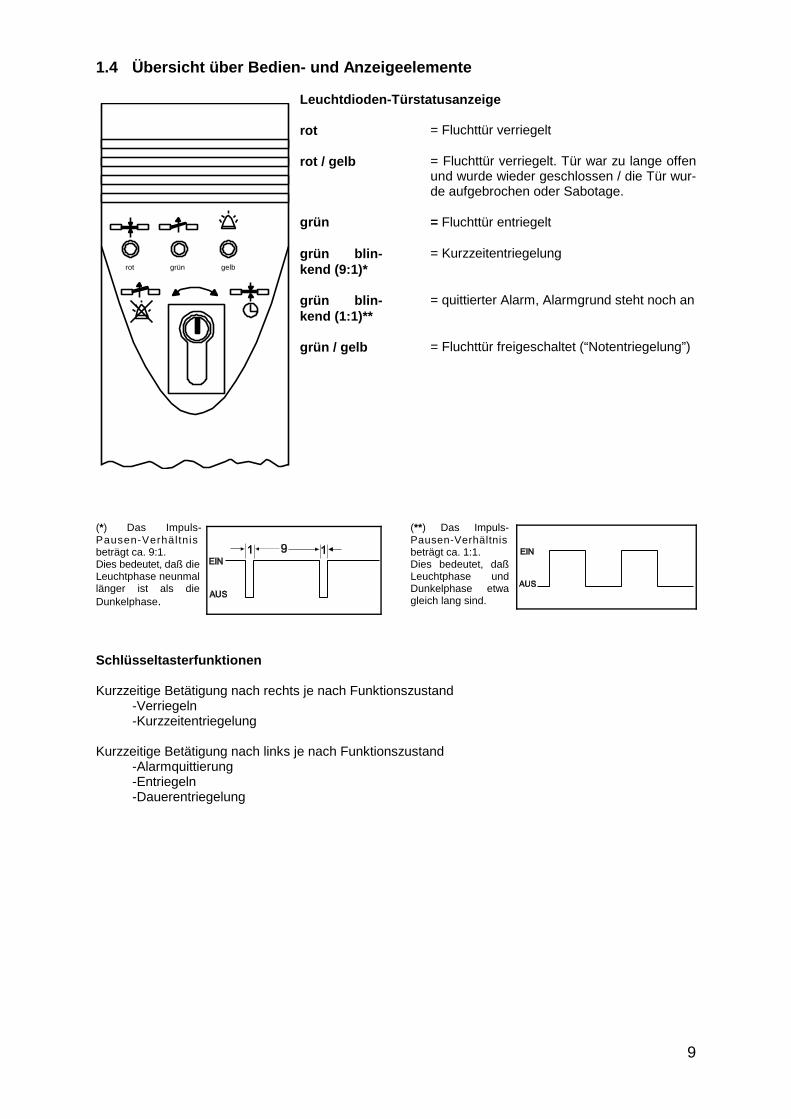
1.4 Übersicht über Bedien- und Anzeigeelemente
Leuchtdioden-Türstatusanzeige
rot = Fluchttür verriegelt
rot / gelb = Fluchttür verriegelt. Tür war zu lange offenund wurde wieder geschlossen / die Tür wur-de aufgebrochen oder Sabotage.
grün = Fluchttür entriegelt
grün blin-kend (9:1)*
= Kurzzeitentriegelung
grün blin-kend (1:1)**
= quittierter Alarm, Alarmgrund steht noch an
grün / gelb = Fluchttür freigeschaltet (“Notentriegelung”)
(*) Das Impuls- (**) Das Impuls-Pausen-Verhältnis Pausen-Verhältnisbeträgt ca. 9:1. beträgt ca. 1:1. Dies bedeutet, daß die Dies bedeutet, daßLeuchtphase neunmal Leuchtphase undlänger ist als die Dunkelphase etwaDunkelphase. gleich lang sind.
Schlüsseltasterfunktionen
Kurzzeitige Betätigung nach rechts je nach Funktionszustand-Verriegeln-Kurzzeitentriegelung
Kurzzeitige Betätigung nach links je nach Funktionszustand-Alarmquittierung-Entriegeln-Dauerentriegelung

10
1.5 Ermittlung einer Alarmbedingung
Am Steuerterminal kann festgestellt werden, wodurch ein Alarm ausgelöst wurde, bzw. welche Alarmbe-dingung noch ansteht.Hinweis: Die Alarmbedingungen sind nur abfragbar, solange der Alarm noch ansteht und die grüneLeuchtdiode im Verhältnis 1:1 blinkt.Dazu muß folgendermaßen vorgegangen werden. Zuerst muß der Alarm quittiert werden. Anschließendden internen Schlüsseltaster zuerst nach links drehen, halten, und die Anzeige im Steuerterminalbeachten. Der gleiche Vorgang ist bei der Schlüsseldrehung nach rechts zu wiederholen. Aus denAnzeigen am Steuerterminal kann aus nachfolgender Tabelle die Ursache des Alarms ermittelt werden.
Tabelle zur Ermittlung der Alarmbedingung:
Auslösekriterium Schlüsselschalter betätigt nach:
Links Rechts
Klemme LED rot grün gelb rot grün gelb
Sabotage am Terminal internoder Bedienteil
Sabotage der Tür (*) intern
Not-Auf intern(es war entriegelt)
Not-Auf intern(es war verriegelt)
Verriegelungsrückmel- 6dung fehlt
Externe Notentriegelung. 13 - 14(Brandmeldeanlage)
Zentralfreigabe keine Anzeige
(*) In diesem Fall blinkt die grüne LED nach Quittierung des Alarms nicht. Wenn der Türkontakt jedoch weiterhingeöffnet ist, wird ein Verriegelungsbefehl nicht angenommen. Das gleiche gilt, wenn ein Tür-offen-Alarm ausgelöstwurde, weil nach einer Kurzzeitfreigabe die Tür zu lange offen blieb.

F3
Anordnungsschema
on
S1
S2
S3
S4
F2
F1
JP-1JP-2
1 5
11
Alle Einstellarbeiten dürfen nur von einer Fachkraft vorgenommen werden!Alle Einstellarbeiten dürfen nur von einer Fachkraft vorgenommen werden!
1.6 Einstellmöglichkeiten am Fluchttür-Steuerterminal
1.6.1 Steckbrücke JP-1JP-1 gesteckt = Voralarm “Ein” (Auslieferungszustand). Diesbedeutet, daß vor einem möglichen Alarm nach Ablauf derTürfreigabezeit ein akustischer Voralarm mit verminderterLautstärke ausgelöst wird. Der potentialfreie Alarmkontaktsowie die optische Anzeige werden vom Voralarm nicht beein-flußt.
JP-1 offen = Voralarm “Aus”. Dies bedeutet, daß ein akusti-scher Voralarm unterdrückt und nach Ablauf der an S2 einge-stellten Zeit der Alarm ausgelöst wird.
1.6.2 Steckbrücke JP-2JP-2 gesteckt = die Dauerentriegelung über den internenSchlüsseltaster des Steuerterminals ist möglich (Auslieferungs-zustand).
JP-2 offen = die Dauerentriegelung über den internen Schlüs-seltaster ist nicht möglich.
1.6.3 Funktionsschalter S 4.1
S 4.1: on (oben) = Türöffnungszeitüberwachung aktiv mitAlarm (Auslieferungszustand).
S 4.1: off (unten) = kein Voralarm bzw. Alarm durch die Türöffnungszeitüberwachung.
1.6.4 Funktionsschalter S 4.2
S 4.2: on (oben) = die Kurzzeitfreigabe ist mit dem internen Schlüsseltaster, über die Klemme 20oder durch den externen Taster möglich (Auslieferungszustand).
S 4.2: off (unten) = die Kurzzeitfreigabe ist nur durch den externen Taster, der an den Klemmen11/12 angeschlossen ist, möglich.
1.6.5 Funktionsschalter S 4.3
S 4.3: on (oben) = die Dauerentriegelung erfolgt sofort nach Betätigung (Auslieferungszustand).S 4.3: off (unten) = die Dauerentriegelung erfolgt erst nach 5 Sekunden ständiger Betätigung.
1.6.6 Funktionsschalter S 4.4
S 4.4: on (oben) = es erfolgt ein akustischer Alarm bei Auslösung der externen Brandmelde-anlage oder nach einer Zentralfreigabe (Auslieferungszustand).
S 4.4: off (unten) = es erfolgt kein akustischer Alarm nach Auslösung der externen Brandmelde-anlage oder nach einer Zentralfreigabe.
1.6.7 Funktionsschalter S 4.5
S 4.5: on (oben) = Betriebsart 2: Steuerterminal arbeitet als Busteilnehmer am Türsteuerbus.
S 4.5: off (unten) = Betriebsart 1: Steuerterminal arbeitet als Einzelgerät im stand-alone-Betrieb(Auslieferungszustand).

12
1.6.8 Vorwahlschalter S1: FreigabezeitZeitbereich: 11 bis 176 Sekunden (11-Sekunden-Raster)
bei Kurzzeitfreigabe:Wird die Kurzzeitfreigabe gestartet, erfolgt die Entriegelung der Tür für die Zeit, die an S1 eingestellt ist.Nach deren Ablauf wird die geschlossene Tür wieder verriegelt. Ist die Tür nach dem Öffnen nichtgeschlossen worden, wird nach Ablauf der Kurzzeitfreigabezeit der Voralarm und nach dessen Ablauf,Alarm ausgelöst (abhängig von Steckbrücke JP-1 und Vorwahlschalter S 4.1).
bei Dauerfreigabe über Klemme 9/10:Wird die Dauerfreigabe eingeleitet, erfolgt die Freigabe der Tür für die Dauer der Ansteuerung. An-schließend erfolgt die Wiederverriegelung der geschlossenen Tür. Ist die Tür nach Ablauf der Dauer-freigabe und nach anschließendem Ablauf der Kurzzeitfreigabezeit nicht geschlossen, wird der Voralarmund nach dessen Ablauf, Alarm ausgelöst (abhängig von Steckbrücke JP-1 und Vorwahlschalter S 4.1).
1.6.9 Vorwahlschalter S2: Voralarmzeit(im Stand-alone-Betrieb)Zeitbereich: 4 bis 64 Sekunden (4-Sekunden-Raster)Wurde Voralarm ausgelöst, bleibt dieser, wenn die Tür nicht geschlossen wird, für die an S2 eingestellteZeit aktiviert. Nach deren Ablauf wird Alarm ausgelöst (abhängig vom Vorwahlschalter S 4.1).
(Im Busbetrieb)Im Busbetrieb muß an diesem Vorwahlschalter die Teilnehmeradresse eingestellt werden. Die Ein-stellung der Teilnehmeradresse ist im Kapitel Busbetrieb beschrieben.Die gewünschte Voralarmzeit muß dann am Bus-Steuerungstableau 925 eingestellt werden.
1.6.10 Vorwahlschalter S3: Alarmzeit(im Stand-alone-Betrieb)Zeitbereich: 11 bis 176 Sekunden (11-Sekunden-Raster) Wurde Alarm ausgelöst, bleibt der akustische Alarm für die an S3 eingestellte Zeit aktiv. Nach derenAblauf wird der akustische Alarm zurückgesetzt. Der potentialfreie Relaiskontakt an den Klemmen 15/16bleibt jedoch geschlossen und der optische Alarm an der Klemme 21 bleibt aktiv, bis der Alarm quittiertwird.
(Im Busbetrieb)Im Busbetrieb muß an diesem Vorwahlschalter der Adressbereich der Teilnehmeradresse eingestelltwerden. Die Einstellung der Teilnehmeradresse ist im Kapitel Busbetrieb beschrieben.Die gewünschte Alarmzeit muß dann am Bus-Steuerungstableau 925 eingestellt werden.
1.7 Busbetrieb
Wird das Fluchttür-Steuerterminal in der Betriebsart 2 am TS-Bus in Verbindung mit einem Bus-Steue-rungstableau 925 betrieben, erfolgt die Steuerung und Überwachung der Fluchttür nach wie vor durchdas Steuerterminal. Der gesamte bereits beschriebene Funktionsumfang des Steuerterminals stehen imBusbetrieb nahezu unverändert zur Verfügung. Die Beschreibung der zusätzlichen Steuerungs- und Überwachungsmöglichkeiten, die das Bus-Steue-rungstableau 925 zur Verfügung stellt, finden Sie in der Bedienungsanleitung zum Bus-Steuerungs-tableau 925.

13
Achtung! Für die Installation und den Betrieb von elektrischen Verriegelungen von Türen inRettungswegen sind baurechtliche Bestimmungen zu beachten!
Die Geräte entsprechen den in der Europäischen Union geltenden Richtlinienbezüglich elektromagnetischer Verträglichkeit (EMV).Bei der Elektroinstallation sind die VDE-Vorschriften sowie die Bestimmungen derörtlichen EVUs zu beachten.
Achtung!An Rauchschutztüren oder Feuerschutztüren dürfen elektrische Verriegelungssystemenur wenn der Verwendbarkeitsnachweis für die betreffende Tür dies vorsieht und nurnach dessen Maßgabe angebracht werden. Ausnahme: Elemente, die auch an bereitshergestellten Feuerschutzabschlüssen angebracht werden dürfen.
Die Übereinstimmung der Geräte mit der “Richtlinie über elektrische Verriegelungs-systeme von Türen in Rettungswegen (EltVTR)” (Bauregelliste A Teil 1, lfd. Nr. 6.19) istgeprüft von der VdS Schadenverhütung GmbH, Köln.
Nr. des Prüfberichts: EVR 99002
2 Montage und Installation

1000 mm (*)
OberkanteFertigfußboden
Einputzdose
Net
zlei
tung
:(n
ur b
ei G
erät
en d
er
1338
-xx
Ser
ie)
Ste
uerle
itung
en
14
2.1 Hinweise zur Montage
Das Fluchttürterminal ist in unmittelbarer Nähe der Fluchttür zu montieren. Das Fluchttür-Steuerterminalist für die Wandmontage vorgesehen. Um baulichen Anforderungen gerecht zu werden, steht eineAufputz-(AP) und eine Unterputz-(UP) Ausführung zur Verfügung. Der UP-Ausführungen liegt zusätzlich eine Einputzdose aus verzinktem Stahlblech und ein Zubehörbeu-tel mit Montagematerial bei. Verwenden Sie bei der Montage die Bohrschablone im Anhang:
* Gemäß der “Richtlinie über elektrische Verriegelungssysteme von Türen in Rettungswegen” muß dasTerminal so positioniert werden, daß sich die Nottaste innerhalb des Bereichs zwischen 850 mm und1200 mm über Oberkante Fertigfußboden (OKFF) befindet. Empfohlen wird dort eine Höhe von 850mm über OKFF.Näheres regelt die jeweilige Landesbauordnung.Soweit der Muster-Erlaß “Bauaufsichtliche Anforderungen an elektrische Verriegelungen von Türenin Rettungswegen -Fassung Juni 1988" in die jeweilige Landesbauordnung übernommen wurde, istzu berücksichtigen, daß dort eine maximale Höhe von 1050 mm über OKFF vorgeschrieben ist. BeiPositionierung der Einputzdose gemäß Maßangabe in obiger Skizze erreicht die Höhe der Nottastedieses Maximalmaß.
– Die Zuleitungen müssen von unten durch die Leitungsdurchführungen im Gehäuseunterteil geführtwerden.
– Die Zuleitungen müssen hinter oder neben dem Steuerterminal geführt und fixiert werden. Es istdarauf zu achten, daß die Zuleitungen nicht durch die Befestigungsschrauben des Steuerterminalsbeschädigt werden.
– Bei der UP-Version sind zunächst die Zuleitungen durch die Bohrungen der Einputzdose zu führen.Anschließend ist die Dose in die Wand einzuputzen. Mit einem 6 mm Bohrer kann direkt durch dieLochungen in den Ecken der Einputzdose gebohrt werden. Mit den Schrauben und Dübeln desZubehörbeutels ist das Gehäuseunterteil zu befestigen.
– Damit die vorgeschriebene maximale Höhe des Notschalters nicht überschritten wird, beachten Siebei der Festlegung der Position der Einputzdose bitte die Maße in der Skizze.
– Die Kabel sind zwischen den Stegen am Gehäuseboden und den Befestigungsdomen für denGehäusedeckel zu führen und mit den Zugentlastungsschellen in dieser Position zu fixieren.
– Der Raum zwischen den Stegen am Gehäuseboden muß freibleiben!– Bei Modell 1338-xx wird durch die linke Kabeleinführung ausschließlich die Netzzuleitung geführt.
Für alle Steuerleitungen wird die rechte Kabeleinführung benutzt.
Die Montage des Steurterminals auf dem Türblatt ist nicht vorgesehen.

AP-Montage UP-Montage
NOT
AUF
NOT
AUF
1.Transparent-Kunststoffhaube abnehmen
2.Aufkleber-"NOT-AUF"entfernen
3.Schraubenlösen
4.Oberteil abnehmen
F3
F2
F1
Öffnen des Gehäuses
Wand Wand
15
2.2 Leitungsauswahl
Bei der Installation muß beachtet werden, daß die Steuerleitungen maximal 300 m und Leitungen zumVerriegelungsteil maximal 100 m lang sein dürfen. Des weiteren muß der Leitungsquerschnitt so gewählt werden, daß die Spannung am Verriegelungsteilbei Vollast und unter Berücksichtigung aller weiteren Verluste, wie z.B. des Spannungabfalls auf derZuleitung, maximal 10% unter der angegebenen Betriebsnennspannung des Verriegelungsteils liegt.
2.3 Servicehinweise
2.3.1 Öffnen des Gehäuses, AP-Montage, UP-Montage

ZUAUF
Arretierung dasSchalterelements lösen.Arretierungshebel in Stell-ung "AUF" drehen.
Multi-LED herausnehmen und durch Multi-LED Typ BA9S 24 V bei 24 V Gerätenbzw.Multi-LED Typ BA9S 12 V bei 12 V Gerätenersetzen.
Wechseln der Multi-LED
90E
Rückansicht Terminaloberteil
90°
Rückansicht Terminaloberteil
Wechseln des Profilhalbzylinders
Sechskantschraube
Trägerblech
Schalter
Schalter
Federschalt-element
ZUAUF
16
2.3.2 Auswechseln der Multi- LED oder des Profilhalbzylinders
Sollte es nötig sein, den eingebauten Profilhalbzylinder gegen ein anderes Modell auszutauschen, z.B.wenn das Fluchttür-Steuergerät in ein vorhandenes Schließsystem integriert werden soll, so muß zuerstder eingebaute Profilhalbzylinder demontiert und anschließend der Austauschzylinder montiert werden.Bei den notwendigen Arbeiten ist auf besondere Sorgfalt zu achten, um Beschädigungen am Steuergerätzu vermeiden. Bitte folgen Sie deshalb den unten aufgeführten Anweisungen.
� Nach dem Lösen und Abnehmen des Gehäuseoberteils ist zunächst die Flachbandleitungauszustecken, die die Leiterplatte im Gehäuseoberteil mit der des Gehäuseunterteils verbin-det. Dies erfolgt durch Ziehen am Steckergehäuse.Ziehen Sie keinesfalls an der Flachbandleitung, da diese sonst beschädigt werden kann.
� Lösen Sie nun die Sechskantschraube, die den Profilhalbzylinder mit dem Befestigungswinkelverbindet.
� Schieben Sie den Profilhalbzylinder nach hinten durch das Gehäuse und entfernen Sie ihn.Beachten Sie hierbei, daß die Federschaltelemente nicht durch den Schließhebel des Zylin-ders beschädigt werden.
� Setzen Sie den neuen Profilhalbzylinder ein, indem Sie diesen von der Gehäuseinnenseitedurch das Gehäuse schieben. Befestigen Sie diesen anschließend mit der Sechskantschraubeso am Befestigungwinkel, daß der Zylinder an der Gehäusefrontseite plan abschließt. DerZylinder muß dabei so justiert werden, daß der Schließhebel beim Schalten am Trägerblechdes Schaltelements anschlägt.
� Überprüfen Sie anschließend, ob der Schließhebel des Profilhalbzylinders die Federschalt-elemente und damit die Schalter ordnungsgemäß betätigt.
� Stellen Sie wieder die Verbindung mit Hilfe der Flachbandleitung her, und schließen Sie dasSteuerterminal.
� Nehmen Sie das Gerät in Betrieb und führen Sie anschließend einen Funktionstest durch.
Modellauswahl:Für das Fluchttür-Steuerterminal müssen Profilhalbzylinder kürzeste Bauform 90� links mit einer Längevon 30 mm bis 35 mm eingesetzt werden.
0 0
17
2.4 Busbetrieb
Wird das Fluchttür-Steuerterminal in der Betriebsart 2 am TS-Bus in Verbindung mit einem Bus-Steue-rungstableau 925 betrieben, erfolgt die Steuerung und Überwachung der Fluchttür nach wie vor durchdas Steuerterminal. Der gesamte bereits beschriebene Funktionsumfang des Steuerterminals sowie derAblauf der einzelnen Funktionen stehen im Busbetrieb nahezu unverändert zur Verfügung. Die Be-schreibung der zusätzlichen Steuerungs- und Überwachungsmöglichkeiten, die das Bus-Steuerungs-tableau 925 zur Verfügung stellt, finden Sie in der Bedienungsanleitung zum Bus-Steuerungstableau 925.
2.4.1 BusanschlußUm das Fluchttürterminal in Verbindung mit dem Bus-Steuerungstableau 925 betreiben zu können, mußeine Datenverbindung über eine Zwei-Draht-Busleitung zwischen den Geräten hergestellt werden.Die Busleitung ist am Fluchttürterminal an den Klemmen A und B anzuschließen. Es ist beim Anschlußzu beachten, daß die Busleitung gepolt ist und daher richtig am Teilnehmer angeschlossen werden muß.Ein Verpolen der Busleitung hätte einen Kurzschluß zur Folge, der das gesamte Bussystem blockiert undzur Zerstörung der Geräte führen kann.
2.4.2 Einstellung der Teilnehmeradresse am Fluchttürterminal Es ist es erforderlich, daß mit dem Schiebeschalter S 4.5 der Busbetrieb eingestellt und jedem Fluchttür-terminal eine Teilnehmeradresse zugewiesen wird, die an den Drehschaltern S2 und S3 einzustellen ist.Dabei ist darauf zu achten, daß keine Teilnehmeradresse doppelt, sowie die Adresse 0 nicht vergebenwird.In der nachfolgenden Beschreibung wird erläutert, wie die Teilnehmeradresse einzustellen ist.
Drehschalter S3 Drehschalter S2
Adressbereiche Einzeladressen innerhalb eines Adressbereichs
Drehschalterstellung Drehschalterstellung� �0 --> Adressbereich 0 bis 15 0 --> Anfangsadresse des Adressbereichs +01 --> Adressbereich 16 bis 31 1 --> Anfangsadresse des Adressbereichs +12 --> Adressbereich 32 bis 47 2 --> Anfangsadresse des Adressbereichs +23 --> Adressbereich 48 bis 63 3 --> Anfangsadresse des Adressbereichs +34 --> Adressbereich 64 bis 79 .5 --> Adressbereich 80 bis 95 .6 --> Adressbereich 96 bis 111 A --> “ ” +107 --> Adressbereich 112 bis 120 B --> “ ” +11
C --> “ ” +12Die Stellung 8 bis F darf an S3 D --> “ ” +13nicht eingestellt werden! E --> “ ” +14
F --> “ ” +15
Die gleichzeitige Drehschalterstellung S3 --> 0 und S2 --> 0 ist nicht zulässig
Beispiel: Es soll die Teilnehmeradresse 58 am Fluchttürterminal eingestellt werden.Der Drehschalter S3 für den Adressbereich muß dazu in Stellung 3 gebracht werden. Diese Einstellungentspricht dem Adressbereich 48-63. Von der Adresse 48 ausgehend, muß nun die Differenz zu dergewünschten Adresse 58, in diesem Fall 10, mit dem Drehschalter S2 für die Einzeladressen eingestelltwerden. Dies wird erreicht, indem der Drehschalter S2 in Stellung A gebracht wird.
Für weitere Hinweise zur Installation sowie zur Leitungsauswahl lesen Sie bitte die Bedie-nungsanleitung zum Bus-Steuerungstableau 925.

18
Technische Daten und Anschlußpläne
2.5 Technische Daten und Anschlußplan für 1338-20/21
2.5.1 Elektrische Daten
PrimärVersorgungsspannung 230 VAC +10% / -15% / 50-60 HzStromaufnahme max. 0,3 ASicherung F3 2 A träge (Kleinstsicherung Typ TR.5)
berührungssichere AusführungDas Gerät muß durch eine leicht zugängliche Trennvorrichtung vom Versorgungsstromkreisgetrennt werden können.
SekundärNennbetriebsspannung 24 VDC ± 5% Sicherheitskleinspannung
(Restwelligkeit max. 120 mVss)Stromaufnahme für externe Verbraucher max. 320 mA
Sicherung F1 1 A träge (Kleinstsicherung Typ TR.5)Sicherung F2 0,1 A träge (Kleinstsicherung Typ TR.5)Kontaktbelastbarkeit der Relais max. 24 V 1A bei ohmscher Last
2.5.2 Technische Daten
Gehäuseabmessungen (B x H x T) AP-Version ca. 92,5 x 250 x 98 mmUP-Version ca. 122 x 280 x 100 mm
Notschaltelement nach DIN VDE 0660 Teil 200Notschalterbeleuchtung durch Multi-LED Typ BA9S 24 VAnzeige Leuchtdioden rot, grün, gelbAkustisches Signal 100 dB / 1mSchutzart DIN 40050 - IP 20Feuchteklasse DIN 40040 - FUmgebungstemperatur 0 bis 35�CEinbaulage senkrecht
2.5.3 Anschließbare Verriegelungsteile
Modell 827 828 331 RR AKRR 351 AKRR(24 V) (24 V) (24 V) (24V)
Stromaufnahme (je Verriegelungsteil) 250 mA 315 mA 160 mA 160 mA
Anzahl 1 1 2 2
Empfohlener Türkon-takttyp und Anzahl je Magnetkontakte Türkontakt Kegelkontakt
Türflügel 10360, 10362, 10365,10370 integriert 10400
1 1

verriegelt
entriegelt
Verriegeln
Entriegeln
Zentral-Freigabe
Entriegelt
Verriegelt
Alarm
Potentialfreier Relaiskontakt.Belastbarkeit: max 1 A, max 24 V
Anschlußklemmen für den Türsteuer-bus (TS-Bus)
Dauerentriegelung (Uhr, Schalter)
Externe Notentriegelungz. B. Brandmeldeanlage
Potentialfreier Relaiskontakt “Alarm”Belastbarkeit: max. 24 V, max. 1 A
Kurzzeitfreigabe
19
D0013502-A0000303
2.5.4 Anschlußplan

20
2.6 Technische Daten und Anschlußplan für 1340-20/21 Version 12V
2.6.1 Elektrische Daten
Nennbetriebsspannung 12 VDCBetriebsspannungsbereich 12 VDC ±10% stabilisierte Gleichspannung
(Restwelligkeit max. 1 Vss)Das Netzteil für die Spannungsversorgung des Geräts muß der DIN EN 60950:1997-11 ent-sprechen!
Eigenstromaufnahme max. 200 mAStromaufnahme für externe Verbraucher max. 1 A
Sicherung F1 1,6 A träge (Kleinstsicherung Typ TR.5)Sicherung F2 0,1 A träge (Kleinstsicherung Typ TR.5)Kontaktbelastbarkeit der Relais max. 24 V 1A bei ohmscher Last
2.6.2 Technische Daten
Gehäuseabmessungen (B x H x T) AP-Version ca. 92,5 x 250 x 98 mmUP-Version ca. 122 x 280 x 100 mm
Notschaltelement nach DIN VDE 0660 Teil 200Notschalterbeleuchtung durch Multi-LED Typ BA9S 12 VAnzeige Leuchtdioden rot, grün, gelbAkustisches Signal 100 dB / 1mSchutzart DIN 40050 - IP 20Feuchteklasse DIN 40040 - FUmgebungstemperatur 0 bis 35�CEinbaulage senkrecht
2.6.3 Anschließbare Verriegelungsteile
Modell 827 828 331 RR AKRR 351 AKRR(12 V) (12 V) (12 V) (12V)
Stromaufnahme (je Verriegelungsteil) 500 mA 630 mA 320 mA 320 mA
Anzahl 2 1 2 2
Empfohlener Türkon-takttyp und Anzahl je Magnetkontakte Türkontakt Kegelkontakt
Türflügel 10360, 10362, 10365,10370 integriert 10400
1 1

rt bl bl gn
Türkontaktz.B. 10400
Pendeltüröffner 351 AKRR 12 V
Anker-kontakt
rt
7 83 4 6
5 6 4 3 2
7 83 4 65
Haftmagnet 828 12 V
Magnet-kontakt
Magnet-kontakt
gegn br
ws gegn br ws
Haftmagnet Modell 827
Haftmagnet Modell 827
7 83 4 6
Funkenlöschdioden an derAnschlußklemme desHaftmagneten wiegezeichnet anklemmen! Typ: 1N4007
=
E
F11,6 AT
F20,1AT
Fluchttür-Steuerterminal 1340-20 (12 V)
NOT-AUFSchalter
1 2 3 4 5 6 7 8 9 10 11 12 13 14 15 16 17 18 19 20 21 22 23 24
D 0V
C D
S1 S2 S3 S4
Funktion S1 - S4 siehe Bedienungsanleitung
A B
Kontaktbelastbarkeit max. 24V / 1A 24W
Potentialfreier Relais-kontakt
+ -
Spannungs-versorgungstabilisiert
12 V DC ±10%
Anordnungsschema
S1 Freigabezeit
S2 *Voralarmzeit
S3 *Alarmzeit
S4 Funktionsschalter
F2
F1
JP-1JP-2
JP-1 gesteckt Voralarm "EIN"
JP-2 gesteckt Dauerentriegelung über internen Schlüsseltaster
* Im Busbetrieb
Teilnehmeradresse
Zentraltableau 725
218 6 7
rtgnge
3 5 4
21
rtgnge
31013 1411
Bedienteil 1332-10 (11)
5 6 4
17 24
() ()
19 20 21 22 23
D0013502A0000203
bl rt rtbl blgn gnrtrt bl rt rtbl blgn gn
Fluchttüröffner 331 RR AKRR 12 VFluchttüröffner 331 RR AKRR 12 V
Anker-kontakt
Rückmel-dekontakt
Anker-kontakt
Rückmel-dekontakt
7 83 4 6
Eine parallele Ansteuerungzweier Türöffner ist auch beiModell 351 AKRR möglich.Die Verschaltung ist dann wiebei Modell 331 dargestelltauszuführen.
21
2.6.4 Anschlußplan
22
2.7 Technische Daten und Anschlußplan für 1340-20/21 Version 24 V
2.7.1 Elektrische Daten
Nennbetriebsspannung 24 VDCBetriebsspannungsbereich 24 VDC ±10% stabilisierte Gleichspannung
(Restwelligkeit max. 1 Vss)Das Netzteil für die Spannungsversorgung des Geräts muß der DIN EN 60950:1997-11 ent-sprechen!
Eigenstromaufnahme max. 150 mAStromaufnahme für externe Verbraucher max. 640 mA
Sicherung F1 1 A träge (Kleinstsicherung Typ TR.5)Sicherung F2 0,1 A träge (Kleinstsicherung Typ TR.5)Kontaktbelastbarkeit der Relais max. 24 V 1A bei ohmscher Last
2.7.2 Technische Daten
Gehäuseabmessungen (B x H x T) AP-Version ca. 92,5 x 250 x 98 mmUP-Version ca. 122 x 280 x 100 mm
Notschaltelement nach DIN VDE 0660 Teil 200Notschalterbeleuchtung durch Multi-LED Typ BA9S 24 VAnzeige Leuchtdioden rot, grün, gelbAkustisches Signal 100 dB / 1mSchutzart DIN 40050 - IP 20Feuchteklasse DIN 40040 - FUmgebungstemperatur 0 bis 35�CEinbaulage senkrecht
2.7.3 Anschließbare Verriegelungsteile
Modell 827 828 331 RR AKRR 351 AKRR(24 V) (24 V) (24 V) (24V)
Stromaufnahme (je Verriegelungsteil) 250 mA 315 mA 160 mA 160 mA
Anzahl 2 2 2 2
Empfohlener Türkon-takttyp und Anzahl je Magnetkontakte Türkontakt Kegelkontakt
Türflügel 10360, 10362, 10365,10370 integriert 10400
1 - 2 1
rt bl bl gn
Türkontaktz.B. 10400
Pendeltüröffner 351 AKRR 24 V
Anker-kontakt
rt
7 83 4 6
5 6 4 3 2 5 6 4 3 2
7 8
3 4
6
5
Haftmagnet 828 24 V Haftmagnet 828 24 V
Magnet-kontakt
Magnet-kontakt
Magnet-kontakt
ge gn br ws ge gn br ws
Haftmagnet Modell 827
Haftmagnet Modell 827
7 83 4 6
Funkenlöschdioden an derAnschlußklemme desHaftmagneten wiegezeichnet anklemmen! Typ: 1N4007
=
E
F11AT
F20,1AT
Fluchttür-Steuerterminal 1340-20 (24V)
NOT-AUFSchalter
1 2 3 4 5 6 7 8 9 10 11 12 13 14 15 16 17 18 19 20 21 22 23 24
D 0V
C D
S1 S2 S3 S4
Funktion S1 - S4 siehe Bedienungsanleitung
A B
Kontaktbelastbarkeit max. 24V / 1A 24W
Potentialfreier Relais-kontakt
+ -
Spannungs-versorgungstabilisiert
24V DC ±10%
Anordnungsschema
S1 Freigabezeit
S2 *Voralarmzeit
S3 *Alarmzeit
S4 Funktionsschalter
F2
F1
JP-1JP-2
JP-1 gesteckt Voralarm "EIN"
JP-2 gesteckt Dauerentriegelung über internen Schlüsseltaster
* Im Busbetrieb
Teilnehmeradresse
Zentraltableau 725
218 6 7
rtgnge
3 5 4
21
rtgnge
31013 1411
Bedienteil 1332-10 (11)
5 6 4
17 24
() ()
19 20 21 22 23
D0013502A00000103
Eine parallele Ansteuerungzweier Türöffner ist auch beiModell 351 AKRR möglich.Die Verschaltung ist dann wiebei Modell 331 dargestelltauszuführen.
bl rt rtbl blgn gnrtrt bl rt rtbl blgn gn
Fluchttüröffner 331 RR AKRR 24 VFluchttüröffner 331 RR AKRR 24 V
Anker-kontakt
Rückmel-dekontakt
Anker-kontakt
Rückmel-dekontakt
7 83 4 6
23
2.7.4 Anschlußplan

24
3 Inbetriebnahme, Wartung, wiederkehrende Prüfung
Einbau und Betrieb von elektrischen Verriegelungen von Türen in Rettungswegen unterliegenbauaufsichtlichen Regelungen, deren Einhaltung sowohl von Seiten des Installateurs als auchseitens des Betreibers sicherzustellen ist.
3.1 Inbetriebnahme und wiederkehrende PrüfungVor der ersten Inbetriebnahme eines elektrischen Fluchttürverriegelungssystems muß der ordnungs-gemäße Einbau aller Elemente und deren elektrischer Anschluß überprüft werden. Besondere Sorgfaltist hierbei auf die Elemente zur Freischaltung der Verriegelung im Gefahrenfall zu verwenden.In der Regel ist der ordnungsgemäße Einbau und die Funktionsfähigkeit der elektrischen Fluchttür-verriegelung durch einen Sachkundigen festzustellen. Darüber hinaus müssen Türen in Rettungswegen mit elektrischen Verriegelungen mindestens einmaljährlich von einem Sachkundigen geprüft werden. Der Sachkundige hat über die wiederkehrendePrüfung eine Bescheinigung auszustellen, die der Betreiber der Bauaufsichtsbehörde auf Verlangenvorzulegen hat.”
Achtung!Bei den vorstehenden Hinweisen handelt es sich um Standardvorgaben. Da der Einsatz vonRettungswegverriegelungen auf Ebene der Bundesländer geregelt ist, sind in jedem Fall diebetreffende Landesbauordnung und die Prüfverordnungen für technische Anlagen zu beachten.
3.2 WartungDie Fluchttürsteuerterminals 1338-20/21 und 1340-20/21 bedürfen keiner Wartung. Treten während desBetriebs oder bei einer der vorgeschriebenen Prüfungen Störungen auf, die nicht durch fehlerhafteInstallation oder Montage verursacht wurden, so ist das betreffende Gerät unverzüglich außer Betrieb zunehmen und zur Überprüfung an den Hersteller zu senden.Die Wartungsfreiheit der Geräte entbindet nicht von der Pflicht zu regelmäßig wiederkehrender Prüfungder Fluchttürverriegelung!
25
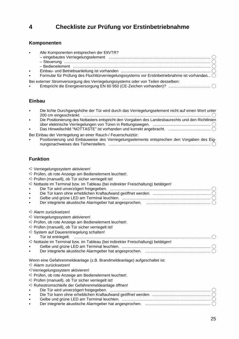
4 Checkliste zur Prüfung vor Erstinbetriebnahme
Komponenten
� Alle Komponenten entsprechen der EltVTR?– eingebautes Verriegelungselement ............................................................................................ �– Steuerung .................................................................................................................................... �– Bedienelement ............................................................................................................................ �
� Einbau- und Betriebsanleitung ist vorhanden ................................................................................. �� Formular für Prüfung des Fluchttürverriegelungssystems vor Erstinbetriebnahme ist vorhanden........ �
Bei externer Stromversorgung des Verriegelungssystems oder von Teilen desselben:� Entspricht die Energieversorgung EN 60 950 (CE-Zeichen vorhanden)? ...................................... �
Einbau
� Die lichte Durchgangshöhe der Tür wird durch das Verriegelungselement nicht auf einen Wert unter200 cm eingeschränkt. ................................................................................................................... �
� Die Positionierung des Nottasters entspricht den Vorgaben des Landesbaurechts und den Richtlinienüber elektrische Verriegelungen von Türen in Rettungswegen. .................................................... �
� Das Hinweilschild “NOTTASTE” ist vorhanden und korrekt angebracht. ...................................... �
Bei Einbau der Verriegelung an einer Rauch-/ Feuerschutztür:� Positionierung und Einbauweise des Verriegelungselements entsprechen den Vorgaben des Eig-
nungsnachweises des Türherstellers. ............................................................................................ �
Funktion
� Verriegelungssystem aktivieren!� Prüfen, ob rote Anzeige am Bedienelement leuchtet!.� Prüfen (manuell), ob Tür sicher verriegelt ist!� Nottaste im Terminal bzw. im Tableau (bei indirekter Freischaltung) betätigen!� Die Tür wird unverzögert freigegeben. ........................................................................................... �� Die Tür kann ohne erheblichen Kraftaufwand geöffnet werden. .................................................... �� Gelbe und grüne LED am Terminal leuchten. ................................................................................ �� Der integrierte akustische Alarmgeber hat angesprochen. .......................................................... �
� Alarm zurücksetzen!� Verriegelungssystem aktivieren!� Prüfen, ob rote Anzeige am Bedienelement leuchtet!.� Prüfen (manuell), ob Tür sicher verriegelt ist!� System auf Dauerentriegelung schalten!� Tür ist entriegelt. ........................................................................................................................... �� Nottaste im Terminal bzw. im Tableau (bei indirekter Freischaltung) betätigen!� Gelbe und grüne LED am Terminal leuchten. ................................................................................ �� Der integrierte akustische Alarmgeber hat angesprochen. ........................................................... �
Wenn eine Gefahrenmeldeanlage (z.B. Brandmeldeanlage) aufgeschaltet ist:� Alarm zurücksetzen!�Verriegelungssystem aktivieren!� Prüfen, ob rote Anzeige am Bedienelement leuchtet!.� Prüfen (manuell), ob Tür sicher verriegelt ist!� Ruhestromschleife der Gefahrenmeldeanlage öffnen!� Die Tür wird unverzögert freigegeben. ........................................................................................... �� Die Tür kann ohne erheblichen Kraftaufwand geöffnet werden. ..................................................... �� Gelbe und grüne LED am Terminal leuchten. ................................................................................ �� Der integrierte akustische Alarmgeber hat angesprochen. ........................................................... �

eff-eff Fritz Fuss GmbH & Co Kommanditgesellschaft auf AktienBildstockstraße 20 72458 Albstadt-EbingenDeutschlandTel.: (07431) 123-0 http/www.effeff.comfax (07431) 123-240/303 [email protected] ASSA ABLOY Group company ASSA ABLOY

OPERATE EMERGENCYEXIT BUTTON ONLY INCASE OF DANGER
Operating and installation instructions
D00135 03
Security and Precision
Emergency exit control terminal 1338-20/21 1340-20/21

Contents
1 Functional characteristics and operation . . . . . . . . . . . . . . . . . . . . . . . . . . . . . . . . . . . . 29
1.1 General description . . . . . . . . . . . . . . . . . . . . . . . . . . . . . . . . . . . . . . . . . . . . . . . . . . . . . . . . . . . . . 301.1.1 Model description . . . . . . . . . . . . . . . . . . . . . . . . . . . . . . . . . . . . . . . . . . . . . . . 30
1.2 Functional characteristics . . . . . . . . . . . . . . . . . . . . . . . . . . . . . . . . . . . . . . . . . . . . . . . . . . . . . . . . 311.2.1 Functional characteristics when switching on or on return of the power supply 311.2.2 Temporary release . . . . . . . . . . . . . . . . . . . . . . . . . . . . . . . . . . . . . . . . . . . . . . 311.2.3 Permanent unlocking . . . . . . . . . . . . . . . . . . . . . . . . . . . . . . . . . . . . . . . . . . . . 321.2.4 Locking . . . . . . . . . . . . . . . . . . . . . . . . . . . . . . . . . . . . . . . . . . . . . . . . . . . . . . . 32
1.3 Alarm . . . . . . . . . . . . . . . . . . . . . . . . . . . . . . . . . . . . . . . . . . . . . . . . . . . . . . . . . . . . . . . . . . . . . . . . 321.3.1 Danger alarm . . . . . . . . . . . . . . . . . . . . . . . . . . . . . . . . . . . . . . . . . . . . . . . . . . 331.3.2 Connection and alarm by means of a fire alarm system (terminal 13/14) . . . . 331.3.3 Sabotage alarm . . . . . . . . . . . . . . . . . . . . . . . . . . . . . . . . . . . . . . . . . . . . . . . . 331.3.4 Alarm due to door break-in . . . . . . . . . . . . . . . . . . . . . . . . . . . . . . . . . . . . . . . . 331.3.5 Dealing with multiple alarms . . . . . . . . . . . . . . . . . . . . . . . . . . . . . . . . . . . . . . . 331.3.6 Monitoring the door opening time . . . . . . . . . . . . . . . . . . . . . . . . . . . . . . . . . . . 34
1.4 Overview of operating and display elements . . . . . . . . . . . . . . . . . . . . . . . . . . . . . . . . . . . . . . . . . . 351.5 Determination of an alarm condition . . . . . . . . . . . . . . . . . . . . . . . . . . . . . . . . . . . . . . . . . . . . . . . . 361.6 Setting possibilities at the emergency exit control terminal . . . . . . . . . . . . . . . . . . . . . . . . . . . . . . . 37
1.6.1 Plug-in jumper JP-1 . . . . . . . . . . . . . . . . . . . . . . . . . . . . . . . . . . . . . . . . . . . . . 371.6.2 Plug-in jumper JP-2 . . . . . . . . . . . . . . . . . . . . . . . . . . . . . . . . . . . . . . . . . . . . . 371.6.3 Function key S 4.1 . . . . . . . . . . . . . . . . . . . . . . . . . . . . . . . . . . . . . . . . . . . . . . 371.6.4 Function key S 4.2 . . . . . . . . . . . . . . . . . . . . . . . . . . . . . . . . . . . . . . . . . . . . . . 371.6.5 Function key S 4.3 . . . . . . . . . . . . . . . . . . . . . . . . . . . . . . . . . . . . . . . . . . . . . . 371.6.6 Function key S 4.4 . . . . . . . . . . . . . . . . . . . . . . . . . . . . . . . . . . . . . . . . . . . . . . 371.6.7 Function key S 4.5 . . . . . . . . . . . . . . . . . . . . . . . . . . . . . . . . . . . . . . . . . . . . . . 371.6.8 Preselection switch S1: Release time . . . . . . . . . . . . . . . . . . . . . . . . . . . . . . . 381.6.9 Preselection switch S2: Pre-alarm time . . . . . . . . . . . . . . . . . . . . . . . . . . . . . . 381.6.10 Preselection switch S3: Alarm time . . . . . . . . . . . . . . . . . . . . . . . . . . . . . . . . . 38
1.7 Bus mode . . . . . . . . . . . . . . . . . . . . . . . . . . . . . . . . . . . . . . . . . . . . . . . . . . . . . . . . . . . . . . . . . . . . . 38
2 Mounting and installation . . . . . . . . . . . . . . . . . . . . . . . . . . . . . . . . . . . . . . . . . . . . . . . . . 39
2.1 Mounting instructions . . . . . . . . . . . . . . . . . . . . . . . . . . . . . . . . . . . . . . . . . . . . . . . . . . . . . . . . . . . . 402.2 Choosing the right cables . . . . . . . . . . . . . . . . . . . . . . . . . . . . . . . . . . . . . . . . . . . . . . . . . . . . . . . . 412.3 Servicing instructions . . . . . . . . . . . . . . . . . . . . . . . . . . . . . . . . . . . . . . . . . . . . . . . . . . . . . . . . . . . . 41
2.3.1 Opening the housing, surface mounting, flush mounting . . . . . . . . . . . . . . . . . 412.3.2 Exchanging the multi-LED or the profile half-cylinder . . . . . . . . . . . . . . . . . . . 42
2.4 Bus mode . . . . . . . . . . . . . . . . . . . . . . . . . . . . . . . . . . . . . . . . . . . . . . . . . . . . . . . . . . . . . . . . . . . . . 432.4.1 Bus connection . . . . . . . . . . . . . . . . . . . . . . . . . . . . . . . . . . . . . . . . . . . . . . . . . 432.4.2 Setting the user address at the emergency exit terminal . . . . . . . . . . . . . . . . 43
2.5 Specifications and terminal diagram for 1338-20/21 . . . . . . . . . . . . . . . . . . . . . . . . . . . . . . . . . . . 442.5.1 Electrical data . . . . . . . . . . . . . . . . . . . . . . . . . . . . . . . . . . . . . . . . . . . . . . . . . . 442.5.2 Specifications . . . . . . . . . . . . . . . . . . . . . . . . . . . . . . . . . . . . . . . . . . . . . . . . . . 442.5.3 Possible connecting locking elements . . . . . . . . . . . . . . . . . . . . . . . . . . . . . . . 442.5.4 Terminal diagram . . . . . . . . . . . . . . . . . . . . . . . . . . . . . . . . . . . . . . . . . . . . . . . 45
2.6 Specifications and terminal diagram for 1340-20/21 Version 12V . . . . . . . . . . . . . . . . . . . . . . . . . 462.6.1 Electrical data . . . . . . . . . . . . . . . . . . . . . . . . . . . . . . . . . . . . . . . . . . . . . . . . . . 462.6.2 Specifications . . . . . . . . . . . . . . . . . . . . . . . . . . . . . . . . . . . . . . . . . . . . . . . . . . 462.6.3 Possible connecting locking elements . . . . . . . . . . . . . . . . . . . . . . . . . . . . . . . 462.6.4 Terminal diagram . . . . . . . . . . . . . . . . . . . . . . . . . . . . . . . . . . . . . . . . . . . . . . . 47
2.7 Specifications and terminal diagram for 1340-20/21 Version 24 V . . . . . . . . . . . . . . . . . . . . . . . . . 482.7.1 Electrical data . . . . . . . . . . . . . . . . . . . . . . . . . . . . . . . . . . . . . . . . . . . . . . . . . . 482.7.2 Specifications . . . . . . . . . . . . . . . . . . . . . . . . . . . . . . . . . . . . . . . . . . . . . . . . . . 482.7.3 Possible connecting locking elements . . . . . . . . . . . . . . . . . . . . . . . . . . . . . . . 482.7.4 Terminal diagram . . . . . . . . . . . . . . . . . . . . . . . . . . . . . . . . . . . . . . . . . . . . . . . 49
3 Commissioning, maintenance, recurring tests . . . . . . . . . . . . . . . . . . . . . . . . . . . . . . . 50
3.1 Commissioning and recurring tests . . . . . . . . . . . . . . . . . . . . . . . . . . . . . . . . . . . . . . . . . . . . . . . . . 503.2 Maintenance . . . . . . . . . . . . . . . . . . . . . . . . . . . . . . . . . . . . . . . . . . . . . . . . . . . . . . . . . . . . . . . . . . 50
4 Checklist for testing prior to initial commissioning . . . . . . . . . . . . . . . . . . . . . . . . . . . . . . 51
29
Note! The relevant statutory building regulations must be observed when installing and
operating electrical locks in escape routes.
Agreement of the units with the "Directive on locking systems for doors in escape routes(EltVTR 12/97)" (Building register A part 1, no. 6.19) has been tested by VdS Schaden-verhütung GmbH, Cologne
No. of the test report: EVR 99002
1 Functional characteristics and operation

30
1.1 General description
The emergency exit control terminal type 1338/1340-20 is designed for the control and monitoring ofindividual emergency exits. It accommodates the entire electronic control circuitry, eliminating the needfor an additional control unit. All relevant operating and control elements are integrated in the controlterminal and therefore do not need to be additionally externally connected.On principle, it is possible to choose between two different operating modes in the 1338/1340-20 controlterminal. In operating mode 1 the control terminal works as a stand-alone unit, meaning that the controlterminal is responsible for the complete control and monitoring of the emergency exit. Operating functionsmust be performed at the control terminal or via an external operator terminal, for example the 1332. In operating mode 2 , the control terminal works as a bus user in the door control bus (TS Bus). In thisoperating mode, an extended operating and monitoring capability is afforded from a central location withbus control panel 925. .
The following functions are available to you with the emergency exit control terminal 1338/1340-20(21):� Release of the emergency exit via an integrated emergency button� External release of the emergency exit (for example by a fire alarm system)� Permanent unlocking using the internal key-operated switch or through an external contact
such as a time switch� Temporary unlocking via the internal key-operated switch or through an externally connected
button� Central release with alarm initiation via an external button� Display of the emergency exit locking status by means of the door status display� Display of an alarm status by means of an acoustic and optical signal � One floating relay contact each for an additional "locked-unlocked" display and for an external
alarm signal � Operation in combination with an external central panel type 725 or an operator terminal
1332-10/11.� Operation as a bus user at the TS-Bus in conjunction with a bus control panel 925 and
upgraded operating and monitoring possibilities (bus technology).
1.1.1 Model description
Emergency exit control terminal type 1338-20/21Alongside the entire electronic control circuit, these control terminals are fitted with an additional powersupply unit which supplies both the electronic circuitry in the control terminal and also the locking ele-ments with the required voltage.
Emergency exit control terminal type 1340-20/21These control terminals have the same functional scope as model 1338-20/21, but do not have aninternal power supply unit. For this reason, it is necessary to supply the control terminals and the lockingelements with the necessary voltage via an external power supply.

31
1.2 Functional characteristics
Over the following pages, the individual functions, the setting possibilities at the control terminal and theconnection of external modules to the emergency exit control terminal are described. Please read throughthese instructions with great care and observe particularly the terminal diagrams and the relevantelectrotechnical datasheets, in order to avoid errors during installation and commissioning. The description is broken down according to subject areas, ensuring the fastest possible localization ofinformation relating to a required function.
1.2.1 Functional characteristics when switching on or on return of the power supply
After switching on the system or after a power failure, the position of the internal emergency button andthe status of all control inputs is interrogated and evaluated by the system. The resulting system switchingstatus is then directly dependent upon these input parameters. If an alarm is triggered after switching onfor which the reason is not immediately recognizable, the cause of the alarm can be discovered andremedied with the aid of the table in the chapter Determination of an alarm condition
1.2.2 Temporary release
The control terminal permits the locked door to be unlocked for the time period set at S1 using the"Temporary release" function. For this to be possible, the internal key-operated switch must be actuatedin the "locking" direction or the control terminal actuated via terminals 11/12 or 17/20.The "Temporary release" status is indicated by the LED flashing at a ratio of 9:11.If the door unlocked using the temporary release function is opened and then closed again, the "Tempo-rary release" is interrupted irrespective of the set release time and the door is locked. However, the doormust be closed again within the set temporary release time, in order not to initiate a pre-alarm or alarmstatus. If the door remains opened, initially a pre-alarm and then the alarm is initiated. This is reset byclosing the door, after which its automatically relocked. The alarm display with the yellow LED remains inplace until acknowledged or until a repeat release is initiated. If the temporary release is initiated via the external buttons at terminals 11/12, the release time can bere-triggered. This means that the release time is restarted by pressing any button. Relocking takes placeafter expiry of the set release time, calculated from the last time the release button was disengaged. If actuation at this input takes place continuously via a switching contact, the door is continuouslyunlocked until the actuation is discontinued. The temporary release time starts automatically afterwards.Once this time has expired, the door is locked again. No relocking takes place after opening and closingthe door during the permanent unlocking status. The "Permanent unlocking" status is displayed by thegreen LED lighting constantly. If the "Temporary release" function is not required, this must be set at function switch S 4.2. Temporaryrelease is then available only via an external button which is connected to terminals 11/12.
S 4.2: On (above)=temporary release is possible using the internal key-operated switch, via terminal 20or through the external buttons (as-delivered status).
S 4.2: Off (below)= temporary release is only possible through the external button which is connected toterminals 11/12.
Note: an alarm occurring during the release time is evaluated.
1) Flashing at a ratio of 9:1 means that the illumination phase of the LED is 9 times longer during theflashing process than the dark phase (2) Flashing at a ratio of 1:1 means that the illumination phase is the same length as the dark phase.

32
1.2.3 Permanent unlocking
The control terminal offers the possibility to unlock a locked door using the "Permanent unlocking"function. This can be carried out in two ways.With the first possibility, the door unlocks immediately when the internal key-operated switch is actuatedin the "unlocking" direction (depending on JP2), or a tripping process takes place via an external contactat the terminals 9/10. With the second possibility, permanent release takes place only after a delay of 5seconds, during which the triggering signal must be active. The command "Permanent unlocking" is notdelayed when tripping takes place at terminals 9/10. An active command at this contact is always executed directly.The permanent unlocking function can also be tripped by an external operator terminal 1332-… or at thecentral panel by actuating the "Unlock" button. The "permanent unlocking" status is displayed by continu-ous illumination of the green LED.The relevant function must be set at the function key S 4.3 and at plug-in jumper JP2.
S 4.3: On (above) =Permanent unlocking takes place immediately after actuating the internalkey-operated switch in the event of a continuous signal at terminal 9/10 ora signal at terminal 19 (as-delivered status).
S 4.3 off (below) =Permanent unlocking only takes place when actuation of the internalkey-operated switch or the signal at terminal 19 has been active for around5 seconds. This setting has no influence on the permanent release contactat terminal 9/10.
JP2 plugged in =Permanent unlocking by the key-operated switch is possible.JP2 not plugged in =Permanent unlocking by the key-operated switch is not possible.
Note: An alarm occurring during the permanent unlocking mode is evaluated.
1.2.4 Locking
A door unlocked in the temporary release or permanent release mode can be locked again by actuatingthe internal key-operated switch in the "lock" direction or by triggering the control terminal via terminals17/20.If the temporary or permanent release mode is active, this is interrupted and the door is locked. Thecondition for locking is that no alarm condition is active and that the door is closed. The "locked" status is indicated by the red LED.
1.3 Alarm
An alarm is triggered as soon as one of the conditions listed below exists. A difference is drawn herebetween three different types of alarm� the danger alarm� the sabotage alarm� the door monitoring time alarm
Acknowledgement: If an alarm has been tripped, this can be reset in two steps. During the first step,initially the alarm must be acknowledged. The acknowledgement is executed by actuating thekey-operated switch in the "unlock" direction. Acknowledging the alarm switches off the acoustic signal,if this has not already ended on expiry of the acoustic alarm time set using S3 (only in stand-aloneoperation. In bus operation, the time must be set at the bus control panel). In addition, the floating contact"Alarm" switches (open). In the display, the yellow LED is extinguished and the green LED starts to flashat a ratio of 1:12. This display indicates that the alarm has been acknowledged, but is not yet active. Reset: In the second step, the cause of the alarm has to be remedied. This means that, for example, anactuated emergency switch has to be pulled out again. Once this has been done, the green LED lights upcontinuously and so signals that there is no longer an alarm status active. The system is now in the

33
"unlocked" status and, when the door is closed, can be switched to the "locked" status. The alarmmemory is deleted when the door is locked.
1.3.1 Danger alarm
The danger alarm can be tripped by o actuation of the Emergency open switch.o a connected fire alarm system being tripped.o actuation of the external "Central release" button in the model 725.o an initiated door locking process cannot be completed within 3 secondsThese conditions cause an alarm to be tripped directly and the door to be unlocked. A danger alarm isdisplayed by permanent illumination of the green and yellow LEDs, and by the internal acoustic alarmtransmitter. In addition, the "Alarm" floating relay contact closes. This can be used to trigger externalmodules.
Acknowledging and resetting danger alarms Acknowledgement and resetting are performed as described above.
1.3.2 Connection and alarm by means of a fire alarm system (terminal 13/14)
Connection and alarm by means of a fire alarm system (terminal 13/14)At the effeff emergency exit control terminal, it is additionally possible to connect the tripping contact ofa fire alarm system (fail unlocked loop). By tripping the fire alarm system, an alarm is given off at thecontrol terminal and the door is immediately unlocked.Important note!If there is no fire alarm contact connected at the control terminal, use a wire bridge to connectterminals 13/14.If the alarm has been tripped by a fire alarm system, the alarm must be acknowledged and reset by thefire alarm system. At the control terminal, it is only possible to acknowledge the alarm. The closed dooris relocked after acknowledgement at the fire alarm system. If the door is opened on acknowledgementat the fire alarm system, the temporary release time starts to count down. If the door remains open, apre-alarm or alarm is initiated.The acoustic alarm by the fire alarm system can be suppressed in the control terminal by turning thefunction key S 4.4 to the OFF position.
1.3.3 Sabotage alarm
The control terminal is fitted with a sabotage contact which signals when the device is opened (byunauthorized persons). This is intended to prevent interference or manipulation at the control terminalwhich would jeopardize operational safety.If the device is opened, an alarm is initiated immediately irrespective of its locking status. This means thatthe floating "Alarm" contact closes and the internal acoustic alarm transmitter is activated. This status isdisplayed by the yellow LED. The door is not unlocked.
1.3.4 Alarm due to door break-in
If the door is broken open, an alarm is tripped immediately. This alarm is displayed by the red and yellowLED as well as an internal acoustic signal transmitter. In addition, the floating "Alarm" relay contactcloses. This can be used to actuate external modules. In contrast to the danger alarm, in this case thedoor is not unlocked. Alarm acknowledgement and reset correspond to the procedure used with a danger alarm. Resetting thealarm by only closing the door is not possible.
34
1.3.5 Dealing with multiple alarms
If an alarm has been tripped, this can be acknowledged as described above. If the same alarm conditionoccurs after acknowledgement, no additional alarm is triggered. This is only displayed by the fact that thegreen LED starts to flash again at a ratio of 1:1. However, if a different alarm condition occurs, a newalarm is tripped.
1.3.6 Monitoring the door opening time
The door is monitored for the maximum admissible opening time. If the door cannot be locked after atemporary release because it is not closed, after the release time preselected with S1 a pre-alarm statusis initiated. After expiry of the pre-alarm time selected with S2, the alarm proper is initiated (in the busmode, the times must be set at the bus control panel). This functional sequence, when active, is alsotripped after termination of a permanent release via terminals 9/10 if the door is not closed.If this function is not required, this can be set at function key S 4.1. S 4.1: On (above) = Monitoring active with alarm (as-delivered status).S 4.1: Off (below) = Monitoring off. After expiry of the temporary release, no pre-alarm and noalarm status occur.
Resetting an alarm after exceeding the door open timeIf an alarm has been tripped by exceeding the door open time, this can be acknowledged by closing thedoor and reset. The door is closed, and in the control terminal the red and yellow LED lights up as anindication that the door has been open for too long. This display can be deleted by unlocking.
Pre-alarmThe pre-alarm is not used as an emergency alarm but as an indication or warning that the door has notbeen closed after a temporary release after the set temporary release time. For this reason, the functionstripped by an alarm are not activated. In detail, this means that the floating "Alarm" relay contact does notclose and the yellow LED is not alight. The pre-alarm is recognizable only by the acoustic alarm given offwith diminishing volume. The duration of the pre-alarm can be set at switch S2 (in the bus mode, the timemust be set at the bus control panel). If the door is closed during this period, the pre-alarm is terminatedand the door locked. If this is not the case, an alarm is triggered.
Conditions for the pre-alarm:o After a temporary release, the opened door has not been closed again.o After termination of a permanent release and subsequent temporary release time, the door is notclosed.
Resetting a pre-alarmIf the pre-alarm has been tripped, there are two possibilities for resetting it. The first possibility is to close the door. The control terminal then changes to the "locked" status. The second possibility is to initiate a temporary or permanent release during the pre-alarm time. If the"Temporary release" is started, please note that this is only possible with the external release button atterminals 11/12. If the acoustic alarm is not wanted, remove plug-in jumper JP-1.
Note: An alarm occurring during the pre-alarm is evaluated.

rot grün gelb
35
1.4 Overview of operating and display elements
LED door status display
red = Emergency exit locked
red / yellow = Emergency exit locked. Door was o-pen for too long and has been closedagain / the door has been broken openor an attempted sabotage has takenplace.
green = Emergency exit unlocked
green flashing (9:1)* = Temporary unlocking
green flashing (1:1)** = Acknowledged alarm, reason for alarmstill active
green / yellow = Emergency exit released ("emergencyunlocking")
(*) The pulse-pause (**)The pulse-pauseratio is appr. 9:1. This ratio is appr.1:1. Thismeans that the light means that the lightphase is nine times phase and the darklonger than the dark phase are approxima-phase. tely the same length.
Key-operated switch functions
Momentary actuation to the right, depending on functional status-Locking-Temporary unlocking
Momentary contact to the left depending on functional status-Alarm acknowledgement-Unlocking-Permanent unlocking

36
1.5 Determination of an alarm condition
At the control terminal, it is possible to determine what has tripped an alarm or which alarm condition isstill active.Note: The alarm conditions can only be investigated as long as the alarm is still active and the green LEDis flashing at a ratio of 1:1.For this purpose, proceed as follows: First acknowledge the alarm. Then turn the internal key-operatedswitch first to the left, hold, and note the display in the control terminal. Repeat the same process whenturning the key to the right. The displays at the control terminal provide an indication of the cause of thealarm.
Table to ascertain the alarm condition:
Key-operated switch actuated to
Left Right
Terminals LED red green yellow red green yellow
Sabotage at the terminal orcontrol unit
Sabotage at the door (*)
Emergency open(was unlocked)
Emergency open(was locked)
No Locked acknowledge-ment
External emergency unlok-king
(fire alarm system)
Central release keine Anzeige
(*)In this case, the green LED does not flash after acknowledging the alarm. However, if the door contact remainsopened, a locking command is not accepted. The same applies if a door-open alarm has been initiated because the door remained open too long after atemporary release.
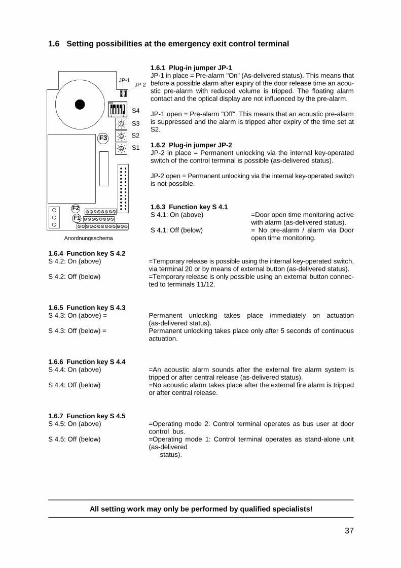
F3
Anordnungsschema
on
S1
S2
S3
S4
F2
F1
JP-1JP-2
1 5
37
All setting work may only be performed by qualified specialists!
1.6 Setting possibilities at the emergency exit control terminal
1.6.1 Plug-in jumper JP-1JP-1 in place = Pre-alarm "On" (As-delivered status). This means thatbefore a possible alarm after expiry of the door release time an acou-stic pre-alarm with reduced volume is tripped. The floating alarmcontact and the optical display are not influenced by the pre-alarm.
JP-1 open = Pre-alarm "Off". This means that an acoustic pre-alarmis suppressed and the alarm is tripped after expiry of the time set atS2.
1.6.2 Plug-in jumper JP-2JP-2 in place = Permanent unlocking via the internal key-operatedswitch of the control terminal is possible (as-delivered status).
JP-2 open = Permanent unlocking via the internal key-operated switchis not possible.
1.6.3 Function key S 4.1 S 4.1: On (above) =Door open time monitoring active
with alarm (as-delivered status).S 4.1: Off (below) = No pre-alarm / alarm via Door
open time monitoring.
1.6.4 Function key S 4.2S 4.2: On (above) =Temporary release is possible using the internal key-operated switch,
via terminal 20 or by means of external button (as-delivered status).S 4.2: Off (below) =Temporary release is only possible using an external button connec-
ted to terminals 11/12.
1.6.5 Function key S 4.3 S 4.3: On (above) = Permanent unlocking takes place immediately on actuation
(as-delivered status).S 4.3: Off (below) = Permanent unlocking takes place only after 5 seconds of continuous
actuation.
1.6.6 Function key S 4.4S 4.4: On (above) =An acoustic alarm sounds after the external fire alarm system is
tripped or after central release (as-delivered status).S 4.4: Off (below) =No acoustic alarm takes place after the external fire alarm is tripped
or after central release.
1.6.7 Function key S 4.5S 4.5: On (above) =Operating mode 2: Control terminal operates as bus user at door
control bus.S 4.5: Off (below) =Operating mode 1: Control terminal operates as stand-alone unit
(as-delivered status).
38
All setting work may only be performed by qualified specialists!
1.6.8 Preselection switch S1: Release timeRelease timeTime range: 11 to 176 seconds (11-second increments)
With temporary release:If the temporary release is started, the door is unlocked for the time set at S1. After expiry of this time, theclosed door is locked again. If the door is not closed after opening, after expiry of the temporary releasetime, the pre-alarm is initiated and after its expiry, the alarm proper (dependent on plug-in jumper JP-1and preselection switch S 4.1).
With temporary release via terminal 9/10:If a permanent release is initiated, the door is released for the period during which actuation takes place.The closed door is subsequently locked again. If the door is not closed after expiry of the permanentrelease and after subsequent expiry of the temporary release time, the pre-alarm is tripped, and after itsexpiry, the alarm proper (dependent on plug-in jumper JP-1 and preselection switch S 4.1).
1.6.9 Preselection switch S2: Pre-alarm time(in stand-alone mode)Time range: 4 to 64 seconds (4-second increments)If a pre-alarm has been tripped, if the door is not closed this remains activated for the time set at S2. Afterexpiry of this time, the alarm proper is tripped (depending on preselection switch S 4.1).
(In the bus mode)In the bus mode, the user address must be set at this preselection switch. The setting procedure for theuser address is described in the chapter Bus mode.The required pre-alarm time must then be set at the bus control panel 925.
1.6.10 Preselection switch S3: Alarm time(in stand-alone mode)Time range: 11 to 176 seconds (11-second increments) If an alarm has been triggered, the acoustic alarm remains active for the time set at S3. After its expiry,the acoustic alarm is reset. The floating relay contact at terminals 15/16 remains closed, however, andthe optical alarm at terminal 21 remains active until the alarm is acknowledged.
(In the bus mode)In the bus mode, the address range of user addresses must be set using this preselection switch. Thesetting of the user address is described in the chapter Bus mode. The required alarm time must then be set at the bus control panel 925.
1.7 Bus mode
If the emergency exit control terminal is operated in operating mode 2 at the TS bus in conjunction witha bus control panel 925, the emergency exit continues to be controlled and monitored via the controlterminal. The entire functional scope of the control terminal as described above is available without anymodification in the bus mode.The description of the additional control and monitoring functions made available by the bus control panel925 is located in the operating instructions for the bus control panel 925.

39
Note! The relevant statutory building regulations must be observed when installing and
operating electrical locks in escape routes!
The devices are in compliance with the directives applicable in the European Unionrelating to electromagnetic compatibility (EMC). During electrical installation, the
VDE stipulations and regulations of the local power utility companies must beobserved.
Note!Electrical locking systems may only be installed at smoke protection or fire doorswhen provided for by the application verification for the relevant door and whensuch systems are mounted in accordance with the stipulations contained in it.
Exception: Elements which may be mounted on already created fire doors.
Agreement of the units with the "Directive on locking systems for doors in escaperoutes (EltVTR 12/97)" (Building register A part 1, no. 6.19) has been tested by VdS
Schadenverhütung GmbH, Cologne
No. of the test report: EVR 99002
2 Mounting and installation

1000 mm (*)
OberkanteFertigfußboden
Einputzdose
Net
zlei
tung
:(n
ur b
ei G
erät
en d
er
1338
-xx
Ser
ie)
Ste
uerle
itung
en
40
2.1 Mounting instructions
The emergency exit terminal must be mounted in the direct vicinity of the emergency exit. The emergencyexit control terminal is intended for wall mounting. In order to address structural requirements, a surfa-ce-mounted and a flush mounted version are available. The flush mounted versions come with an additional flush mounted socket in galvanized sheet steel andan accessory bag containing mounting materials. When mounting, use the drilling template provided inthe annex.
* In accordance with the "Directive on electrical locking systems for doors in escape routes", the controlmodule as well as the terminal module must be positioned so that the emergency key is in the area between850 mm and 1200 mm above the upper edge of the finished floor (OKFF). Here, a height of 850 mm aboveOKFF is recommended.The respective building regulations appertaining to the individual Federal States stipulate further details. Where the model decree "Requirements of the Building Supervisory Authorities imposed on Electrical Locksfor Doors in Escape Routes - Draft June 1988" has been adopted in the respective State Building Regula-tions, please take into account that here a maximum height of 1050 mm over OKFF is stipulated.When positioning the flush mounting box in accordance with the dimensions in the sketch above, the heightof the emergency button reaches this maximum measurement.
� The supply lines must be guided from below through the cable glands in the bottom part of thehousing.
� The supply lines must be guided behind or next to the control terminal and fixed. Pay attention toensure that the supply lines are not damaged by the fixing screws of the control terminal.
� In the flush-mounting version, initially the supply lines must be guided through the boreholes in theflush mounting box. Using these screws and dowels in the accessory bag, fasten the bottom partof the housing.
� To ensure that the prescribed maximum height of the emergency switch is not exceeded, pleasenote the centre of the sketch when fixing the position of the flush-mounting box.
� The cables must be guided between the webs on the housing floor and the fixing domes for thehousing lid, and must be fixed in this position with the strain relief clips.
� The space between the webs on the housing floor must remain free!� In model 1338-xx the mains supply line is only guided through the left-hand cable gland.
For all control lines, the right-hand cable entry is used.
The control terminal is not intended to be mounted on the door leaf.

NOT
AUF
NOT
AUF
1. 2. 3. 4.
F3
F2
F1
Take away thetransparent plasticcover!
Remove the label“EMERGENCYEXIT BUTTON!
Unscrew thefixing screws
Remove the upperpart of the ousing!
Opening the housing
Surface mounting Flush mounting
wallwall
41
2.2 Choosing the right cables
When installing, remember that the control cables may be no longer than 300 m and lines to the lockingpart no longer than 100 m long. In addition, the cable cross-section must be selected so that the voltage at the locking element underload, and taking into consideration all other possible losses such as the voltage drop at the supply line, isno more than 10% below the specified rated operating voltage of the locking element.
2.3 Servicing instructions
2.3.1 Opening the housing, surface mounting, flush mounting

90E
90°
Changing the Multi-LED Changing the profile cylinder
Back view of upper part of the Terminal
hexagon socket screw
switch
switch
spring-returnswitching element
sheet steel carrier
Unlock the fixing mechanismof the switching element byturning the locking lever inthe open direction andremove the switchingelement!
open locked
Take off the Multi-LED andreplace it by type BA 9S!Observe the operatingvoltage!!
42
2.3.2 Exchanging the multi-LED or the profile half-cylinder
Should it be necessary to exchange the installed profile half-cylinder for a different model, e.g. if you wishto integrate the emergency exit control unit into an existing locking system, initially the integrated profilehalf-cylinder must be dismantled and subsequently the exchange cylinder mounted. When performing thenecessary work, take particular care to avoid damage at the control unit. Please therefore follow theinstructions provided below.
� After releasing and removing the upper part of the housing, initially the ribbon cable which connectsthe pcb in the upper part of the housing to the lower part of the housing must be unplugged. Thisis done by pulling it out at the plug housing.Never pull on the ribbon cable itself, as it could otherwise be damaged.
� Now release the hexagonal screw which connects the profile half-cylinder to the fastening bracket.� The push the profile half-cylinder backwards through the housing and remove it, ensuring that the
spring switching elements are not damaged by the closing lever of the cylinder. � Insert the new profile half-cylinder by pushing it from the inside of the housing through the housing.
Then fasten it with the hexagonal screw to the fixing bracket in such a way that the cylinder closesflush with the front of the housing, adjusting the cylinder in such a way that the closing lever comesto a stop at the backing plate of the switching element when switching.
� Then check whether the closing level of the profile half cylinder correctly actuates the springswitching elements and therefore the switches.
� o Restore the connection with the aid of the ribbon cable, and close the control terminal.� o Start up the unit and subsequently carry out a function test.
Model selection:For use with the emergency exit control terminal, the shortest 90° left-hand profile half cylinders with alength of 30 mm to 35 mm must be used.

0 0
43
2.4 Bus mode
If the emergency exit control terminal is to be used in operating mode 2 at the TS-Bus in conjunction witha bus control panel 925, control and monitoring of the emergency exit continues to be performed by thecontrol terminal. The complete functional scope of the control terminal as described above and also thesequence of the individual functions are available practically without modification in the bus mode. Thedescription of additional control and monitoring possibilities made available by bus control panel 925 aredescribed in the operating instructions for the bus control panel 925.
2.4.1 Bus connectionTo allow the emergency exit terminal to be operated in conjunction with the bus control panel 925, a dataconnection must be created via a two-wire bus line between the units. The bus line must be connected atthe emergency exit terminal at terminals A and B. When connecting, ensure that the bus line is poled andconsequently has to be correctly connected to the user. Reverse polarity at the bus line would result in ashort circuit which would block the complete bus system and which can destroy the units.
2.4.2 Setting the user address at the emergency exit terminal Bus operation must be set using slide switch S 4.5, and each emergency exit terminal assigned a useraddress. This is set using rotary switches S2 and S3, paying attention to ensure that no user address isassigned twice, and that the address 0 is not assigned.The description below explains how to set the user address.
Rotary switch S3 Rotary switch S2 Address range Individual addresses within an address range
Rotary switch setting Rotary switch setting¯ ¯0 --> Address range 0 to 15 0--> Starting address of address range +01 --> Address range 16 to 31 1--> Starting address of address range +12 --> Address range 32 to 47 2--> Starting address of address range +23 --> Address range 48 to 63 3--> Starting address of address range +34 --> Address range 64 to 79 .5 --> Address range 80 to 95 .6 --> Address range 96 to 111 A--> " " +107 --> Address range 112 to 120 B-->" " +11
C-->" " +12The positions 8 to F may not be D--> " +13set at S3! E-->" " +14
F-->" " +15
Simultaneous rotary switch setting S3 --> 0 and S2 --> 0 is not admissible
Example: You wish to set emergency exit address 58 at the emergency exit terminal.For this, the rotary switch S3 for the address must be moved to position 3. This setting corresponds to theaddress range 48-63. Starting from address 48, the difference to the required address 58, in this case 10,must be set using the rotary switch S2 for the individual addresses. This is achieved by moving the rotaryswitch S2 to position A.
For further information on the installation and on the selection of cables, please read the operatinginstructions for the bus control panel 925.

44
Specifications and terminal diagrams
2.5 Specifications and terminal diagram for 1338-20/21
2.5.1 Electrical data
PrimarySupply voltage 230 VAC +10% / -15% / 50-60 HzCurrent consumption max. 0.3 AFuse F3 2 A slow-blowing (sub-miniature type TR.5)
protected versionThe device must be configured to permit isolation from the supply circuit by means of an easilyaccessible isolating device.
SecondaryRated operating voltage 24 VDC ± 5% safety extra-low voltage
(residual ripple max. 120 mVss)Current consumption for external consumers max. 320 mA
Fuse F1 1 A slow-blowing (sub-miniature type TR.5)Fuse F2 0.1 A slow-blowing (sub-min. type TR.5)Relay contact load capacity max. 24 V 1A under ohmic load
2.5.2 Specifications
Housing dimensions (W x H x D) Surface version appr. 92.5 x 250 x 98 mmFlush version appr. 122 x 280 x 100 mm
Emergency switching element to DIN VDE 0660 Part 200Emergency switch lighting by Multi-LED Type BA9S 24 VDisplay LEDs red, green yellowAcoustic signal 100 dB / 1mProtection rating DIN 40050 - IP 20Humidity class DIN 40040 - FAmbient temperature 0 to 35°CMounting position vertical
2.5.3 Possible connecting locking elements
Model 827 828 331 RR AKRR 351 RR AKRR(24 V) (24 V) (24 V) (24V)
Current consumption
(per locking element)250 mA 315 mA 160 mA 160 mA
Number 1 1 2 2
Recommended doorcontact
type and number perdoor leaf
Magnetic contacts Door contact Taper contact10360, 10362, 10365,10370 integrated 10400
1 1integrated

Floating relais contact.Admissible load: max 1 A, max 24 V
Terminals for thedoor control bus(TS-bus)
Permanent unlocking (timer, switch)
External Emergency Open(i.e. Fire alarm system)
Floating relais contact “Alarm”Admissible load: max. 24 V, max. 1 A
Temporary release
Centralrelease
Lock
Unlock
Locked
Unlocked
Alarm
Locked
Unlocked
45
2.5.4 Terminal diagram

46
2.6 Specifications and terminal diagram for 1340-20/21 Version 12V
2.6.1 Electrical data
Rated operating voltage 12 VDCOperating voltage range 12 VDC ±10% stabilized direct voltage
(residual ripple max. 1 Vss)The power supply unit for the voltage supply of the device must correspond to DIN EN60950:1997-11!
Intrinsic current consumption max. 200 mACurrent consumption for external consumers max. 1 A
Fuse F1 1.6 A slow-blowing (sub-miniature fuse type.5)
Fuse F2 0.1 A slow-blowing (sub-miniature fuse type.5)
Relay contact load capacity max. 24 V 1A under ohmic load
2.6.2 Specifications
Housing dimensions (W x H x D) Surface version appr. 92.5 x 250 x 98 mmFlush version appr. 122 x 280 x 100 mm
Emergency switching element to DIN VDE 0660 Part 200Emergency switch lighting by Multi-LED type BA9S 12 VDisplay LEDs red, green, yellowAcoustic signal 100 dB / 1mProtection rating DIN 40050 - IP 20Humidity class DIN 40040 - FAmbient temperature 0 to 35°CMounting position vertical
2.6.3 Possible connecting locking elements
Model 827 828 331 RR AKRR 351 RR AKRR(12 V) (12 V) (12 V) (12V)
Current consumption
(per locking element)500 mA 630 mA 320 mA 320 mA
Number 1 1 2 2
Recommended doorcontact
type and number perdoor leaf
Magnetic contacts Door contact Taper contact10360, 10362, 10365,10370 integrated 10400
1integrated

5 6 4 3 2
7 83 4 65
Holding magnet 828 12 V
Reed-contact
Reed-contact
gegn br
ws ge gn br ws
Holding magnetmodel 827
Holding magnetmodel 827
7 83 4 6
=
Connect freewheelingdiodes asshown! type: 1N4007
Parallel operating of two dooropeners can also be made withmodel 351 RR AKRR. In thiscase the connection has to bemade as shown with model331 RR AKRR.
Escape door strike for swingdoors model 351 RR AKRR 12 V
3 4 6
Doorcontact
7 8
gn rdblrd bl rd rdbl
E1 2 3 4 5 6 7 8 9 10 11 12 13 14 15 16 17 18 19 20 21 22 23 24
D 0V
C D
S1 S2 S3 S4
A B
F2
F1
JP-1JP-2
JP1: plugged: prealarm “ON”JP2: plugged: permanent unlocking via internal key operated push button contact
S4: function switches
S3: *alarm time
S2: *prealarm time
S1: temporary release time
*) In bus mode: user adress
Arrangementschematical
218 6 73 5 4
21 31013 1411 5 6 4
17 24
() ()
19 20 21 22 23
ye gn rd
Operating panel 1332-10/11
D0013503A0000203
Escape door strikemodel 331 RR AKRR 12 V
Armature-contact
Monitoring-contact
Armature-contact
7 83 4 6
gnblrd bl rd gnbl rd gnblrd bl rd gnbl rd
Monitoring-contact
Escape door strikemodel 331 RR AKRR 12 V
Escape door control terminal 1340-20 (12 V)
F 11,6 Aslow
F 20,1 Aslow
EMERGENCYOPENswitch
For function S1 to S4 seeoperating instructions
Floating relaiscontactAdmissible load:max. 1 Amax. .24 V
Power supply12 V DC ±10%stabilized
ye gn rd
Central control panel 725
rd = redgn = greenbl = blueye = yellowbr =brownwht = white
47
2.6.4 Terminal diagram

48
2.7 Specifications and terminal diagram for 1340-20/21 Version 24 V
2.7.1 Electrical data
Rated operating voltage 24 VDCOperating voltage range 24 VDC ±10% stabilized direct voltage
(residual ripple max. 1 Vss)The power supply unit for the voltage supply of the device must correspond to DIN EN60950:1997-11!
Intrinsic current consumption max. 150 mACurrent consumption for external consumers max. 640 mA
Fuse F1 1 A slow-blowing (sub-miniature fuse type.5)
Fuse F2 0.1 A slow-blowing (sub-miniature fuse type.5)
Relay contact load capacity max. 24 V 1A under ohmic load
2.7.2 Specifications
Housing dimensions (W x H x D) Surface version: appr. 92.5 x 250 x 98 mmFlush version appr. 122 x 280 x 100 mm
Emergency switching element to DIN VDE 0660 Part 200Emergency switch lighting by Multi-LED Type BA9S 24 VDisplay LEDs red, green, yellowAcoustic signal 100 dB / 1mProtection rating DIN 40050 - IP 20Humidity class DIN 40040 - FAmbient temperature 0 to 35°CMounting position vertical
2.7.3 Possible connecting locking elements
Model 827 828 331 RR AKRR 351 RR AKRR(24 V) (24 V) (24 V) (24 V)
Current consumption
(per locking element)250 mA 315 mA 160 mA 160 mA
Number 2 2 2 2
Recommended doorcontact
type and number perdoor leaf
Magnetic contacts Door contact Taper contact10360, 10362, 10365,10370 integrated 10400
1integrated

5 6 4 3 2
7 8
3 4
6
5
Holding magnet 828 24 V
Reed-contact
5 6 4 3 2
Holding magnet 828 24 V
Reed-contact
Reed-contact
gegn br
ws ge gn br ws
Holding magnetmodel 827
Holding magnetmodel 827
7 83 4 6
=
Connect freewheelingdiodes asshown! type: 1N4007
Parallel operating of two dooropeners can also be made withmodel 351 RR AKRR. In thiscase the connection has to bemade as shown with model331 RR AKRR.
Escape door strike for swingdoors model 351 RR AKRR 24 V
3 4 6
Doorcontact
7 8
gn rdblrd bl rd rdbl
E1 2 3 4 5 6 7 8 9 10 11 12 13 14 15 16 17 18 19 20 21 22 23 24
D 0V
C D
S1 S2 S3 S4
A B
F2
F1
JP-1JP-2
JP1: plugged: prealarm “ON”JP2: plugged: permanent unlocking via internal key operated push button contact
S4: function switches
S3: *alarm time
S2: *prealarm time
S1: temporary release time
*) In bus mode: user adress
Arrangementschematical
218 6 73 5 4
21 31013 1411 5 6 4
17 24
() ()
19 20 21 22 23
ye gn rd
Operating panel 1332-10/11
D0013503A0000203
Escape door strikemodel 331 RR AKRR 24 V
Armature-contact
Monitoring-contact
Armature-contact
7 83 4 6
gnblrd bl rd gnbl rd gnblrd bl rd gnbl rd
Monitoring-contact
Escape door strikemodel 331 RR AKRR 24 V
Escape door control terminal 1340-20 (24 V)
F 11,6 Aslow
F 20,1 Aslow
EMERGENCYOPENswitch
For function S1 to S4 seeoperating instructions
Floating relaiscontactAdmissible load:max. 1 Amax. .24 V
Power supply24 V DC ±10%stabilized
ye gn rd
Central control panel 725
rd = redgn = greenbl = blueye = yellowbr =brownwht = white
49
2.7.4 Terminal diagram

50
3 Commissioning, maintenance, recurring tests
The installation and operation of electrical locking systems for doors in escape routes are subject tobuilding supervisory regulations. Adherence to these regulations must be ensured by both the installerand the operator.
3.1 Commissioning and recurring testsPrior to initial commissioning of an electrical emergency exit locking system, correct installation of allelements and their electrical connection must be checked. Particular care must be applied here to theelements for releasing the locking system in case of danger.As a rule, the correct mounting and function of the electrical emergency exit locking system must beapproved by an expert. In addition, doors in escape routes which are fitted with electrical locks must be tested at least once ayear by an expert. The expert is required to issue a certificate confirming repeated testing, which the usermust present to the building supervisory authorities on request.
Note!The instructions provided above relate to standard specifications. As the application of escaperoute locking systems is regulated on the Federal State level, the relevant State Governmentbuilding legislation and test stipulations for technical equipment must be observed.
3.2 MaintenanceThe emergency exit control terminals 1338-20/21 and 1340-20/21 require no maintenance. Should faultsoccur during operation or in one of the prescribed tests which are not caused by faulty installation ormounting, the relevant device must be decommissioned immediately and sent to the manufacturer forchecking. Freedom from maintenance does not exonerate the user from the obligation to perform regular tests ofthe emergency exit locking system.

51
4 Checklist for testing prior to initial commissioning
Components
� All components comply with the EltVTR– Integrated locking element .......................................................................................................... �–Control system .............................................................................................................................. �–Operating element ....................................................................................................................... �
� Installation and operating instructions available .............................................................................. �� Form sheet for testing prior to initial commissioning is available ................................................... �
In the event of an external power supply of the locking system or of parts of it:� Compliance with energy supply EN 60 950 (CE symbol available) ................................................ �
Installation
� The clear pass-through height of the door is not restricted to a value under 200 cm by the lockingelement ........................................................................................................................................... �
� Positioning of the emergency button corresponds to the stipulations of State building legislation andthe directives relating to electrical locking systems for doors in escape routes. ............................ �
� The informative sign "EMERGENCY BUTTON" is available and correctly mounted. .................... �
When mounting the locking system on a smoke / fire door:� The position and mounting method used for the locking element complies with the stipulations
provided in the door manufacturer's proof of suitability . ................................................................ �
Functional characteristics
Activate the locking system! Check whether the red display is alight at the control element! Check (manually) whether the door is securely locked! Actuate the emergency button in the terminal / control panel (with indirect release)!� The door is released without delay. ................................................................................................ �� The door can be opened without exerting considerable force. ...................................................... �� Yellow and green LED light up at the terminal. .............................................................................. �� The integrated acoustic alarm transmitter has responded. ............................................................ �
Reset the alarm! Activate the locking system! Check whether the red display is alight at the operating element!. Check (manually) whether the door is securely locked! Switch the system to permanent unlocking!� The door is unlocked. .................................................................................................................... � Actuate the emergency button in the terminal / panel (in case of indirect release)!� Yellow and green LED light up at the terminal. .............................................................................. �� The integrated acoustic alarm transmitter has responded. ........................................................... �
If a danger signalling system (e.g. fire alarm system) is connected: Reset the alarm! Activate the locking system! Check whether the red display is alight at the operating element! Check (manually) whether the door is securely locked! Open the closed current loop of the danger signalling system!� The door is released without delay. ................................................................................................ �� The door can be opened without exerting considerable force. ...................................................... �� Yellow and green LED light up at the terminal. ............................................................................... �� The integrated acoustic alarm transmitter has responded. ........................................................... �

eff-eff Fritz Fuss GmbH & Co Kommanditgesellschaft auf AktienBildstockstraße 20 72458 Albstadt-EbingenDeutschlandTel.: (07431) 123-0 http/www.effeff.comfax (07431) 123-240/303 [email protected] ASSA ABLOY Group company ASSA ABLOY


![Fachbereich Mathematik/Informatik Mathematische ...obelix.physik.uni-bielefeld.de/...skriptKap1-2.nb.pdf · [4] Wolfram, S.: Das Mathematica−Buch, Addison−Wesley 1998 (ISBN 3−8273−1338−4)](https://img.pdfslide.org/doc/110x75/5eda2501b3745412b570d7d9/fachbereich-mathematikinformatik-mathematische-4-wolfram-s-das-mathematicaabuch.jpg)