Embed Size (px)
Citation preview

METSYS KG METSYS KG..............................................................tlahnI ...................................................stnetnoC 3....................
..................................................snu rebü riW ................................................ynapmoC ruO tuobA 4.....
................................tiehrehciS ................. ........................................................ytefaS...... 5....................
.......................................................etakifitreZ .................................................setacifitreC 6..................
7................metsyS gnikcaP raludoM eht fo segatnavdA...........smetsyskcaP neraludom sed elietroV
etrovtkudorP ...............................................eli ...............................................segatnavdA tcudorP 8......
etkudorP stcudorP.............................................nemhaR KG eiD ........................................................semarF KG ehT 61..
71..........................................................gnimaN cisaB...............................gnunneneB elleipiznirP
..........................................................03S-KPS.......................................................03S-KPS 81......
..........................................................05S-KPS.......................................................05S-KPS 02......
hKPS............................................................hKPS ........................................................... 22...........
KPS..............................................................KPS ........................................................... 42.............
-KPS...........................................................F-KPS ..........................................................F 62...........
....................................RPS..............................................................RPS ....................... 72............
82..............................................MR snoitarteneP dnuoR..............................MR negnurhüfhcruddnuR
......................................HM eludomdradnatS 03................................................HM seludoM dradnatS
.................................................MF seludoM gnilliF...............................................MF eludomllüF 33.....
43...............MAR /PTDA seludoM suidaR dna sretpadA......MAR /PTDA eludoM neidaR dnu retpadA
egdeW........................................DAK gnuthcidbalieK .......................................................DAK laeS 63..
dnE.......................................DAE gnuthcidbadnE ...........................................................DAE laeS 63...
.....................PWZ nettalpnehcsiwZ ................ 3......................................................PWZ setalP neewT 7
...........................SAV nebiehcssgnureknareV 73...........................................................SAV setalP yatS
...................................................snoituloS laicepS.............................................negnusölrednoS 83......
.............................röhebuZ osseccA............................. ...................................................seir 93.............
..................................VME ............................. ..........................................................CME 04..................
efliH troppuSleW..................................gnulhefpmeßiewhcsniE 4....................................................snoitcurtsnI gnid 6
..................nemharkcaP gnusiewnaegatnoM 74...........semarF gnikcaP eht rof snoitcurtsnI gnitnuoM
gnitnuoM.....negnurhüfhcruddnuR gnusiewnaegatnoM 84......snoitarteneP dnuoR eht rof snoitcurtsnI
alusnI...............................................eleipsiebreilosI .............................................selpmaxE noit 94.......
.......................looT erawtfoS KG ....................................................looT erawtfoS KG.................... 05....
M................................neflihsgnunalP elleunaM 15.................................................sdiA-gninnalP launa
3
4
snu rebü riW
hcis tah na gnafnA no metsyS-KG ned fua
-tmäs netnnok oS .treisilaizeps uabffihcS
-edrofnA nerednoseb eid fua etkudorP ehcil
-nI negireiwhcs tfo eid ehclew ,negnur
hcis tim droB na negnugnidebsnoitallats
-egleiz ,ellenhcS .nedrew treimitpo ,negnirb
negnulkciwtnE ethceregsixarp dnu etethcir
sad ssad ,ieb uzad negart metsyskcaP-KG
red negnuredrofnA nednegiets gidnäts ned
nelleutka med remmi dnu driw thcereg tieZ
gifuäh saw ,thcirpstne kinhceT red dnatS
“egnatS red nov„ lairetamdradnatS tim thcin
.tsi nehcierre uz
regne tatluseR sad tsi metsyskcaP-KG saD
netfreW nenedeihcsrev tim tiebranemmasuZ
enniS mi znag ,nebeirtebsnoitallatsnI dnu
:netätiroirP reresnu
ehänsixarP ,tiekgissälrevuZ dnu tiehrehciS
-sgnutsieL-sierP senegowegsua nie dnu
.sintlährev
V
ynapmoC ruO tuobA
,gninnigeb yrev eht mor metsyS-KG sah
.gnidliubpihs fo sdeen eht ni desilaiceps
ni dedeeccus sah ynapmoc eht ,suhT
eht teem ot stcudorp sti fo lla gnisimitpo
eht morf gnimmets stnemeriuqer laiceps
netfo hcihw snoitidnoc noitallatsni tluciffid
tnempoleved lacitcarp ,tsaF .draob no rucco
-irtnoc a sekam sesoprup cificeps rof krow
eht taht gnirusne sdrawot noitub -KG
metsyS gnikcaP ylidaets sʼyadot slifluf
syawla ti taht dna stnemeriuqer gniworg
,tra eht fo etats tsetal eht ot sdnopserroc
yb eveihca ot elbissopmi netfo si hcihw
F
lairetam ”gep-eht-ffo“ dradnats fo snaem
.enola
fo tluser eht si metsyS noitarteneP-KG ehT
dna sdraypihs suoirav htiw noitarepooc esolc
drocca etelpmoc ni seinapmoc noitallatsni
,ytilibailer ,ytefas yleman ,seitiroirp ruo htiw
.yenom rof eulav doog dna ,ytilacitcarp
& eniraM ITG ,ireitnacniF ,seivaN lanoitanretnI ,keinhcetortkelE noorC ,yvaN namreG ,ssoV + mholB ,tfreW WTM rekA ,BBAMAS ,SNEMEIS ,puorG draypihS leetS esnedO ,tfreW reyeM ,tfreW wonraW renreavK ,erohsffO & eniraM hcetmI ,WDH ,erohsffO
draypihS iatnaY ,draypihS gnajizgnaY ,nedmE ekreweesdroN ,awoN aksnicezczS ainzcotS ,ainydG ainzcotS ,scinortcelE
:nednuK reresnu eginiE :stneilc ruo fo emoS
5
cyanmagentayellowblack
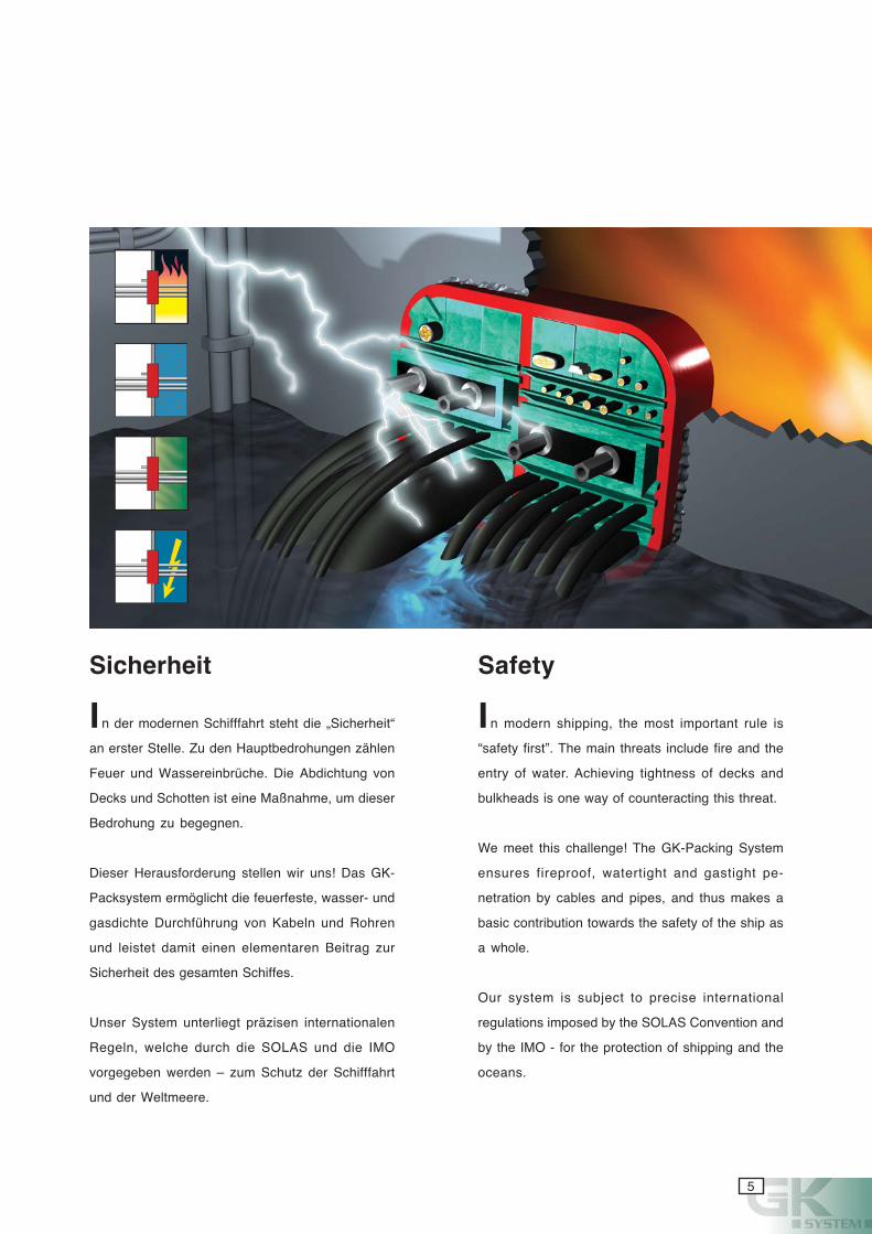
n der modernen Schifffahrt steht die „Sicherheit“
an erster Stelle. Zu den Hauptbedrohungen zählen
Feuer und Wassereinbrüche. Die Abdichtung von
Decks und Schotten ist eine Maßnahme, um dieser
Bedrohung zu begegnen.
Dieser Herausforderung stellen wir uns! Das GK-
Packsystem ermöglicht die feuerfeste, wasser- und
gasdichte Durchführung von Kabeln und Rohren
und leistet damit einen elementaren Beitrag zur
Sicherheit des gesamten Schiffes.
Unser System unterliegt präzisen internationalen
Regeln, welche durch die SOLAS und die IMO
vorgegeben werden – zum Schutz der Schifffahrt
und der Weltmeere.
Sicherheit
I
Safety
n modern shipping, the most important rule is
“safety first”. The main threats include fire and the
entry of water. Achieving tightness of decks and
bulkheads is one way of counteracting this threat.
We meet this challenge! The GK-Packing System
ensures fireproof, watertight and gastight pe-
netration by cables and pipes, and thus makes a
basic contribution towards the safety of the ship as
a whole.
Our system is subject to precise international
regulations imposed by the SOLAS Convention and
by the IMO - for the protection of shipping and the
oceans.
I
6
ßämeg gidnätsllov tsi metsyskcaP-KG sa
dnu tetseteg )81(457.A noituloseR OMI red
-llesegsnoitakifissalK netnaveler nella nov
.nedrow treiborppa netfahcs
dnu -kceD rüf netleg negnussaluZ eiD
A nessalkdnarB ßämeg nenoitallatsnittohcS
red sdradnatS eid nedrew nihretieW .H dnu
.tllüfre DEM
ni hcilßeilhcssua nedrew stseT eresnU
nresuähdnarB netreitiderkka dnu nelartuen
.trhüfeghcrud
-KG sad tsi tiekgidnätsebreueF red nebeN
saG negeg rab 3,0 sib tsefkcurd metsyskcaP
nelläflezniE ni ,ressaW negeg rab 4 sib dnu
-hcan netiekgitsefkcurD erehöh hcua dnis
negeil negnussaluZ OMI ned nebeN .rabsiew
-lettüR dnu -kcohcS .B.z eiw esiewhcaN hcua
.rov tiekgitsef
-eganamstätilauQ sad tsi hcildnätsrevtsbleS
OSI .meg snemhenretnU sed metsystnem
.treizifitrez 1009
-hcaN dnu etakifitreZesiew
dna setacifitreCsnoitacifireV
D -moc neeb sah metsyS gnikcaP-KG eh
tsetal eht htiw ecnadrocca ni detset yletelp
-pa ylluf si dna )81(457 noituloseR OMI
noitacifissalc tnaveler eht fo lla yb devorp
-ni eht revoc slavorppa ehT .seiteicos
erif ot gnidnopserroc saera ni snoitallats
DEM eht ,eromrehtruF .H dna A sessalc
.dellifluf era sdradnats
dna lartuen yb ylno tuo deirrac era stset ruO
.seinapmoc gnitset-erif detidercca
gnikcaP-KG eht ,ecnatsiser erif sa llew sA
3.0 ot pu sag ot tnatsiser-erusserp si metsyS
.rab 4 ot pu retaw ot dna rab
noitacifirev ,slavorppa OMI eht ot noitidda nI
ot ecnatsiser rof demrofrep neeb osla sah
.elpmaxe rof ,noitarbiv dna kcohs
wen gniriuqca yltnatsnoc era ew esuaceB
.yrassecen fi su tcatnoc esaelp ,setacifitrec
-eganam ytilauq sʼynapmoc ruo ,yllarutaN
ecnadrocca ni deifitrec era serudecorp tnem
.1009 OSI htiw
T
7
cyanmagentayellowblack
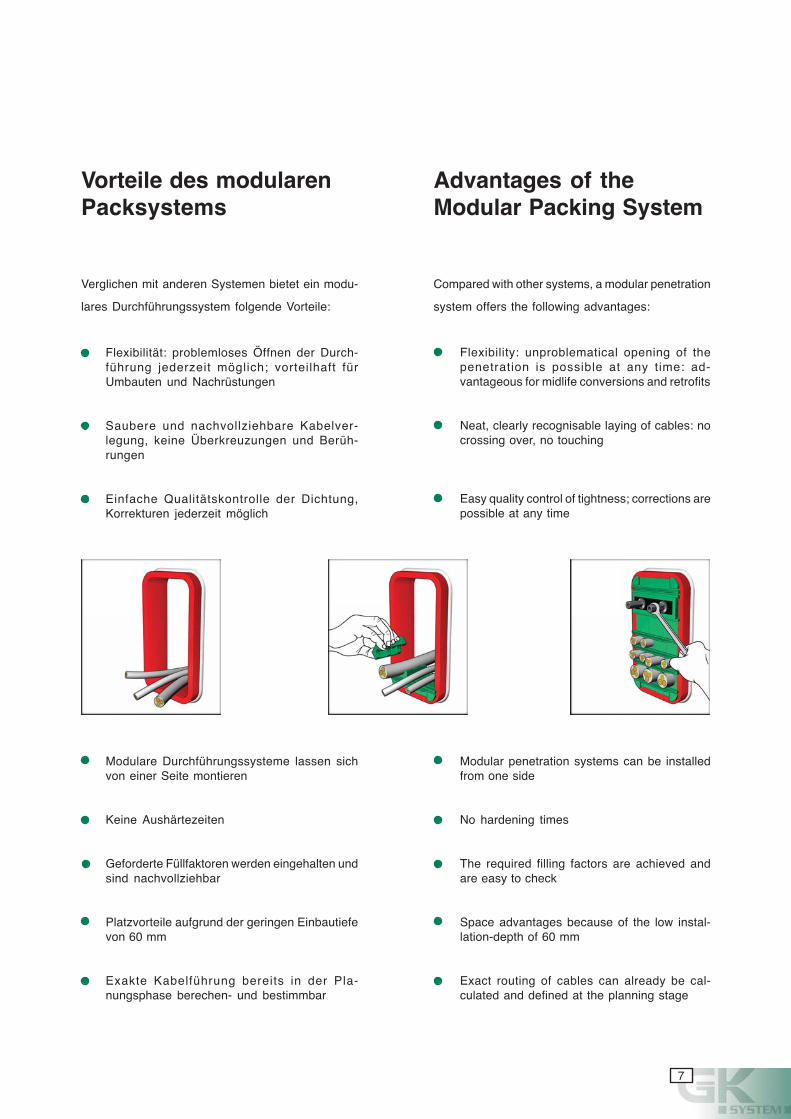
Verglichen mit anderen Systemen bietet ein modu-
lares Durchführungssystem folgende Vorteile:
Flexibilität: problemloses Öffnen der Durch-führung jederzeit möglich; vorteilhaft fürUmbauten und Nachrüstungen
Saubere und nachvollziehbare Kabelver-legung, keine Überkreuzungen und Berüh-rungen
Einfache Qualitätskontrolle der Dichtung,Korrekturen jederzeit möglich
Flexibility: unproblematical opening of thepenetration is possible at any time: ad-vantageous for midlife conversions and retrofits
Neat, clearly recognisable laying of cables: nocrossing over, no touching
Easy quality control of tightness; corrections arepossible at any time
Vorteile des modularenPacksystems
Compared with other systems, a modular penetration
system offers the following advantages:
Advantages of theModular Packing System
Modulare Durchführungssysteme lassen sichvon einer Seite montieren
Keine Aushärtezeiten
Geforderte Füllfaktoren werden eingehalten undsind nachvollziehbar
Platzvorteile aufgrund der geringen Einbautiefevon 60 mm
Exakte Kabelführung bereits in der Pla-nungsphase berechen- und bestimmbar
Modular penetration systems can be installedfrom one side
No hardening times
The required filling factors are achieved andare easy to check
Space advantages because of the low instal-lation-depth of 60 mm
Exact routing of cables can already be cal-culated and defined at the planning stage
8
elietrovtkudorP
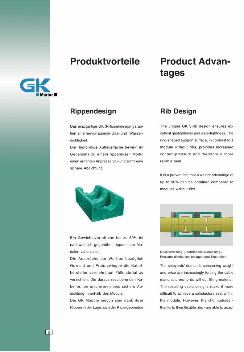
-narag ngisedneppiR-3 KG egitragiznie saD
-ressaW dnu -saG ednegarrovreh enie treit
.tiekgithcid
mi tkriweb ehcälfegalfuA egimröfgnir eiD
ludoM nesolneppir menie uz ztasnegeG
enie timos dnu kcurdsserpnA nethöhre nenie
.gnuthcidbA erehcis
-navdA tcudorPsegat
ngisedneppiR ngiseD biR
tsi %03 uz sib nov lietrovsthciweG niE
-oM nesolneppir rebünegeg hcilsiewhcan
.neleizre uz nelud
hcilgüzeb netfreW red ehcürpsnA eiD
-lebaK eid negniwz sierP dnu thciweG
uz lairetamllüF fua trhemrev relletsreh
-aK nednereitluser suarad eiD .nethcizrev
-bA erehcis enie nerewhcsre nemrofleb
.sludoM sed blahrenni gnuthcid
rerhi knad dnis hcodej eludoM KG eiD
eirtemoeglebaK red hcis ,egaL red ni neppiR
-xe serusne ngised bir-3 KG euqinu ehT
ehT .ssenthgitretaw dna ssenthgitsag tnellec
a ot tsartnoc ni ,ecafrus troppus depahs-gnir
desaercni sedivorp ,sbir tuohtiw eludom
erom a erofereht dna erusserp-tcatnoc
.laes elbailer
fo egatnavda thgiew a taht tcaf nevorp a si tI
ot derapmoc deniatbo eb nac %03 ot pu
.sbir tuohtiw seludom
thgiew gninrecnoc sdnamed ʼsdraypihs ehT
elbac eht gnicrof ylgnisaercni era ecirp dna
.lairetam gnillif tuohtiw od ot srerutcafunam
erom ti ekam sngised elbac gnitluser ehT
nihtiw laes yrotcafsitas a eveihca ot tluciffid
- seludom KG eht ,revewoH .eludom eht
tpada ot elba era - sbir elbixelf rieht ot sknaht
/)gnulletsraD enebeirtrebü( gnulietrevkcurD)noitartsulli detareggaxe( noitubirtsid erusserP
9
cyanmagentayellowblack
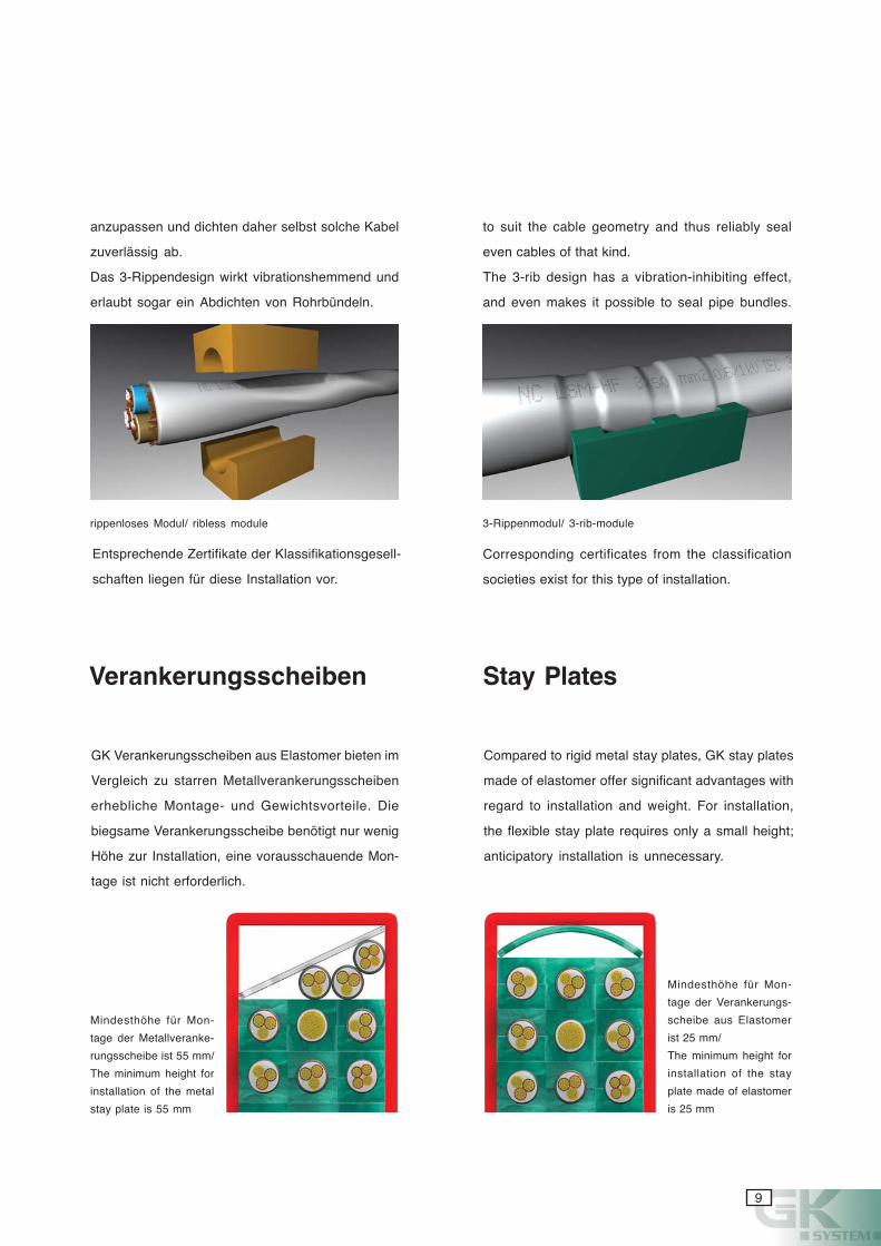
Verankerungsscheiben
anzupassen und dichten daher selbst solche Kabel
zuverlässig ab.
Das 3-Rippendesign wirkt vibrationshemmend und
erlaubt sogar ein Abdichten von Rohrbündeln.
rippenloses Modul/ ribless module 3-Rippenmodul/ 3-rib-module
to suit the cable geometry and thus reliably seal
even cables of that kind.
The 3-rib design has a vibration-inhibiting effect,
and even makes it possible to seal pipe bundles.
Corresponding certificates from the classification
societies exist for this type of installation.
GK Verankerungsscheiben aus Elastomer bieten im
Vergleich zu starren Metallverankerungsscheiben
erhebliche Montage- und Gewichtsvorteile. Die
biegsame Verankerungsscheibe benötigt nur wenig
Höhe zur Installation, eine vorausschauende Mon-
tage ist nicht erforderlich.
Stay Plates
Compared to rigid metal stay plates, GK stay plates
made of elastomer offer significant advantages with
regard to installation and weight. For installation,
the flexible stay plate requires only a small height;
anticipatory installation is unnecessary.
Mindesthöhe für Mon-
tage der Metallveranke-
rungsscheibe ist 55 mm/
The minimum height for
installation of the metal
stay plate is 55 mm
Mindesthöhe für Mon-
tage der Verankerungs-
scheibe aus Elastomer
ist 25 mm/
The minimum height for
installation of the stay
plate made of elastomer
is 25 mm
Entsprechende Zertifikate der Klassifikationsgesell-
schaften liegen für diese Installation vor.
01
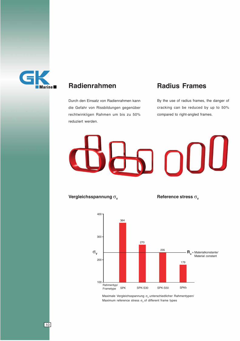
nnak nemharneidaR nov ztasniE ned hcruD
rebünegeg negnudlibssiR nov rhafeG eid
%05 uz sib mu nemhaR negilkniwthcer
.nedrew treizuder
fo regnad eht ,semarf suidar fo esu eht yB
%05 ot pu yb decuder eb nac gnikcarc
.semarf delgna-thgir ot derapmoc
nemharneidaR semarF suidaR
gnunnapsshcielgreV σV sserts ecnerefeR σV
gnunnapsshcielgreV elamixaM σ V /nepytnemhaR rehcildeihcsretnu sserts ecnerefer mumixaM σ V sepyt emarf tnereffid fo
KPS 05S-KPS03S-KPS hKPS
463
072
532
971
004
σV
/pytnemhaRepytemarF
R e =
003
002
001
/etnatsnoklairetaMtnatsnoc lairetaM

11
cyanmagentayellowblack
Verteilung der mechanischen Spannung Distribution of mechanical stress
Radienadapter und Radienmodule
A combination of the radius frames with modules
ADTP and RAM provides additional installation
space for cables and pipes, or permits the use of
smaller frames with the corresponding advantages
with respect to weight and cost.
Radius Adapters and Radius Modules
SPK Rahmen mit σVmax =364 N/mm2 bei einer Referenzspannung von 100 N/mm2/
SPK Frames with σVmax =364 N/mm2 at a reference stress of 100 N/mm2
SPKh Rahmen mit σVmax =179 N/mm2 bei einer Referenzspannung von 100 N/mm2/
SPKh Frames with σVmax =179 N/mm2 at a reference stress of 100 N/mm2
[N/mm2]
0
35
65
100
135
170
200
235
364
Eine Kombination der Radienrahmen mit Modulen
ADTP und RAM ergibt zusätzlichen Montageraum
für Kabel und Rohre bzw. erlaubt die Verwendung
von kleineren Rahmen mit den entsprechenden Ge-
wichts- und Kostenvorteilen.
21
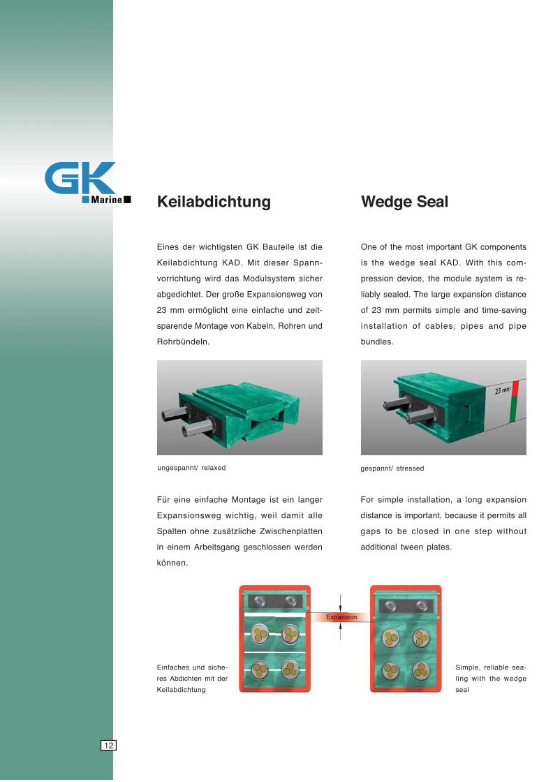
gnuthcidbalieK
dexaler /tnnapsegnu desserts /tnnapseg
eid tsi elietuaB KG netsgithciw red seniE
-nnapS reseid tiM .DAK gnuthcidbalieK
rehcis metsysludoM sad driw gnuthcirrov
nov gewsnoisnapxE eßorg reD .tethcidegba
-tiez dnu ehcafnie enie thcilgömre mm 32
dnu nerhoR ,nlebaK nov egatnoM edneraps
.nlednübrhoR
regnal nie tsi egatnoM ehcafnie enie rüF
ella timad liew ,githciw gewsnoisnapxE
nettalpnehcsiwZ ehcilztäsuz enho netlapS
nedrew nessolhcseg gnagstiebrA menie ni
.nennök
stnenopmoc KG tnatropmi tsom eht fo enO
-moc siht htiW .DAK laes egdew eht si
-er si metsys eludom eht ,ecived noisserp
ecnatsid noisnapxe egral ehT .delaes ylbail
gnivas-emit dna elpmis stimrep mm 32 fo
epip dna sepip ,selbac fo noitallatsni
.seldnub
laeS egdeW
noisnapxE
noisnapxe gnol a ,noitallatsni elpmis roF
lla stimrep ti esuaceb ,tnatropmi si ecnatsid
tuohtiw pets eno ni desolc eb ot spag
.setalp neewt lanoitidda
-ehcis dnu sehcafniEred tim nethcidbA ser
gnuthcidbalieK
-aes elbailer ,elpmiSegdew eht htiw gnil
laes
13
cyanmagentayellowblack
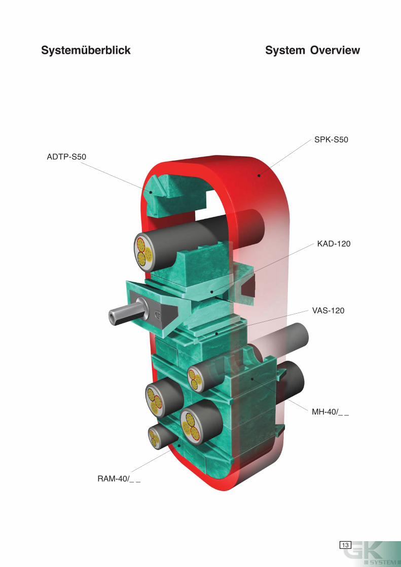
ADTP-S50
SPK-S50
KAD-120
VAS-120
MH-40/_ _
RAM-40/_ _
Systemüberblick System Overview

14
cyanmagentayellowblack

15
cyanmagentayellowblack
16
cyanmagentayellowblack
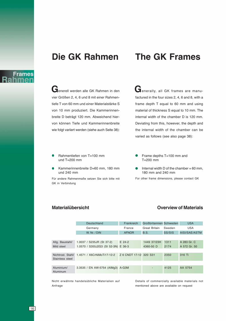
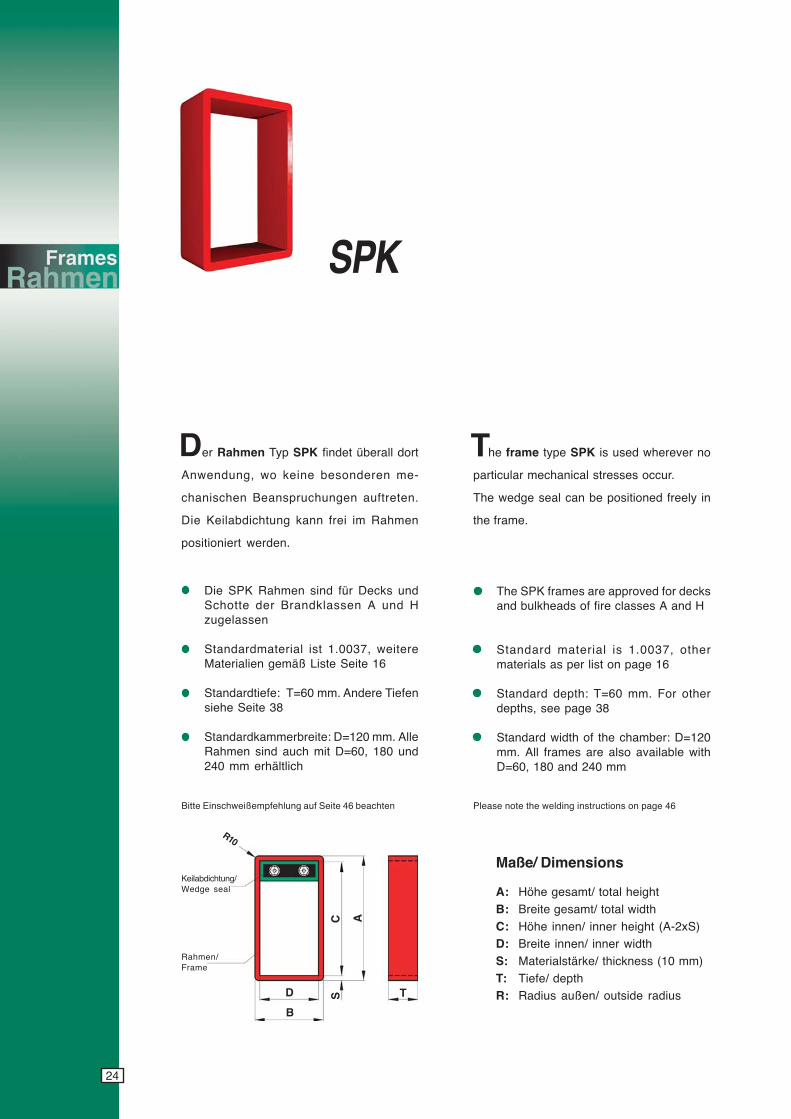
Die GK Rahmen The GK Frames
enerell werden alle GK Rahmen in den
vier Größen 2, 4, 6 und 8 mit einer Rahmen-
tiefe T von 60 mm und einer Materialstärke S
von 10 mm produziert. Die Kammerinnen-
breite D beträgt 120 mm. Abweichend hier-
von können Tiefe und Kammerinnenbreite
wie folgt variiert werden (siehe auch Seite 38):
Rahmentiefen von T=100 mmund T=200 mm
Kammerinnenbreite D=60 mm, 180 mmund 240 mm
enerally, all GK frames are manu-
factured in the four sizes 2, 4, 6 and 8, with a
frame depth T equal to 60 mm and using
material of thickness S equal to 10 mm. The
internal width of the chamber D is 120 mm.
Deviating from this, however, the depth and
the internal width of the chamber can be
varied as follows (see also page 38):
Frame depths T=100 mm andT=200 mm
Internal width D of the chamber = 60 mm,180 mm and 240 mm
Für andere Rahmenmaße setzen Sie sich bitte mit
GK in Verbindung
Deutschland Frankreich Großbritannien Schweden USA
Germany France Great Britain Sweden USA
W. Nr. / DIN AFNOR B.S. SS/SIS AISI/SAE/ASTM
Allg. Baustahl/ 1.0037 / S235JR (St 37-2) E 24-2 1449 37/23H 1311 A 283 Gr. C
Mild steel 1.0570 / S355J2G3 (St 52-3N) E 36-3 4360-50 D 2174 A 572 Gr. 50
Nichtrost. Stahl/ 1.4571 / X6CrNiMoTi17-12-2 Z 6 CNDT 17-12 320 S31 2350 316 TiStainless steel
Aluminium/ 3.3535 / EN AW-5754 (AIMg3) A-G3M - 4125 AA 5754Aluminum
Materialübersicht
For other frame dimensions, please contact GK
Overview of Materials
G G
Nicht erwähnte handelsübliche Materialien auf
Anfrage
Details of commercially available materials not
mentioned above are available on request
17
cyanmagentayellowblack
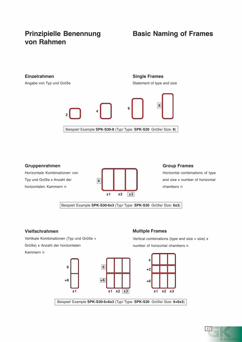
Prinzipielle Benennungvon Rahmen
Angabe von Typ und Größe
Einzelrahmen
Horizontale Kombinationen von
Typ und Größe x Anzahl der
horizontalen Kammern n
Gruppenrahmen
Vertikale Kombinationen (Typ und Größe +
Größe) x Anzahl der horizontalen
Kammern n
Vielfachrahmen
Basic Naming of Frames
Statement of type and size
Single Frames
Horizontal combinations of type
and size x number of horizontal
chambers n
Group Frames
Vertical combinations (type and size + size) x
number of horizontal chambers n
Multiple Frames
6
x1 x2 x3
Beispiel/ Example SPK-S30-8 (Typ/ Type: SPK-S30 Größe/ Size: 8)
+6
x1 x2 x3
6
+6
6
x2 x3
+2
4
+6
24
68
x1 x1
Beispiel/ Example SPK-S30-6x3 (Typ/ Type: SPK-S30 Größe/ Size: 6x3)
Beispiel/ Example SPK-S30-6+6x3 (Typ/ Type: SPK-S30 Größe/ Size: 6+6x3)
18
cyanmagentayellowblack
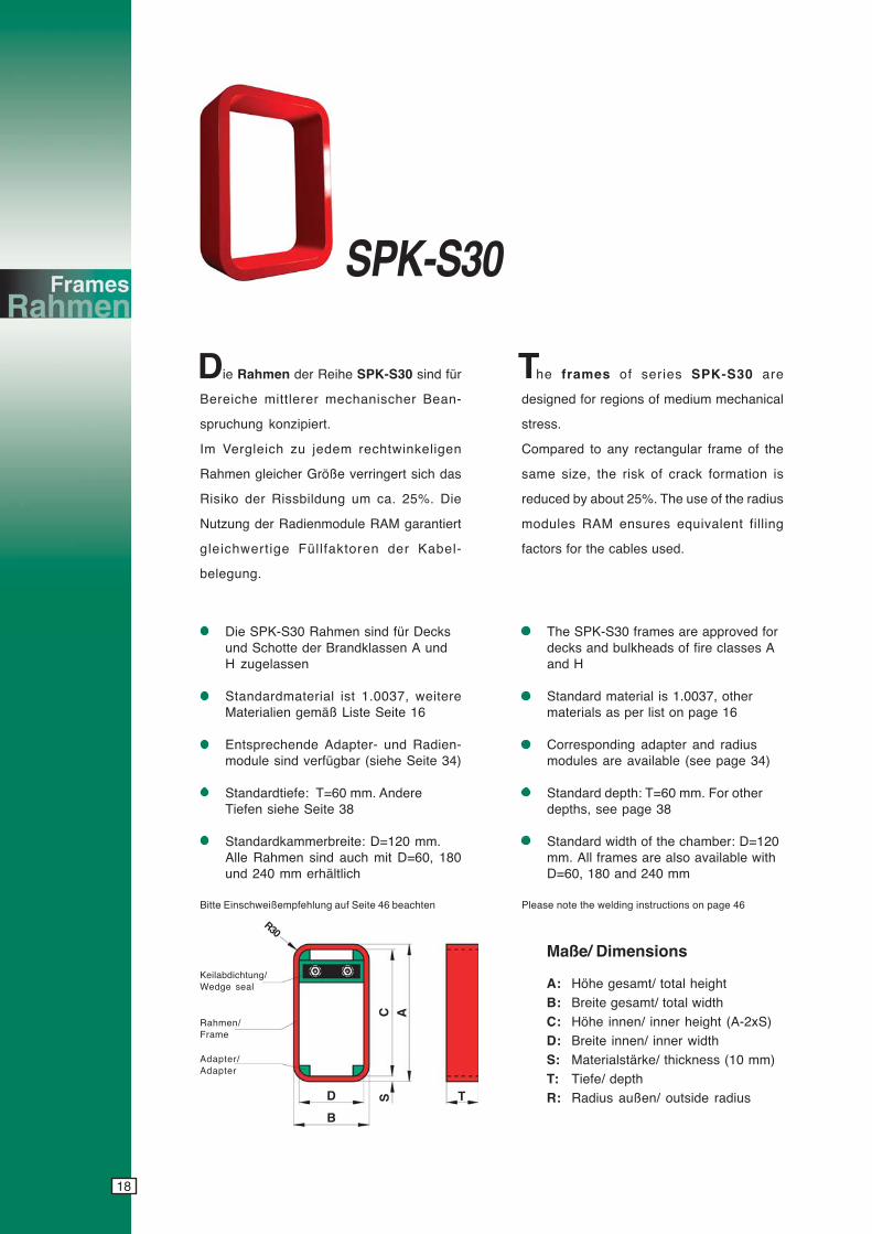
SPK-S30
ie Rahmen der Reihe SPK-S30 sind für
Bereiche mittlerer mechanischer Bean-
spruchung konzipiert.
Im Vergleich zu jedem rechtwinkeligen
Rahmen gleicher Größe verringert sich das
Risiko der Rissbildung um ca. 25%. Die
Nutzung der Radienmodule RAM garantiert
gleichwertige Füllfaktoren der Kabel-
belegung.
he frames of series SPK-S30 are
designed for regions of medium mechanical
stress.
Compared to any rectangular frame of the
same size, the risk of crack formation is
reduced by about 25%. The use of the radius
modules RAM ensures equivalent filling
factors for the cables used.
Die SPK-S30 Rahmen sind für Decksund Schotte der Brandklassen A undH zugelassen
Standardmaterial ist 1.0037, weitereMaterialien gemäß Liste Seite 16
Entsprechende Adapter- und Radien-module sind verfügbar (siehe Seite 34)
Standardtiefe: T=60 mm. AndereTiefen siehe Seite 38
Standardkammerbreite: D=120 mm.Alle Rahmen sind auch mit D=60, 180und 240 mm erhältlich
Maße/ Dimensions
A: Höhe gesamt/ total height
B: Breite gesamt/ total width
C: Höhe innen/ inner height (A-2xS)D: Breite innen/ inner width
S: Materialstärke/ thickness (10 mm)
T: Tiefe/ depthR: Radius außen/ outside radius
Bitte Einschweißempfehlung auf Seite 46 beachten Please note the welding instructions on page 46
Keilabdichtung/Wedge seal
Rahmen/Frame
R30
D
B
S T
C A
Adapter/Adapter
The SPK-S30 frames are approved fordecks and bulkheads of fire classes Aand H
Standard material is 1.0037, othermaterials as per list on page 16
Corresponding adapter and radiusmodules are available (see page 34)
Standard depth: T=60 mm. For otherdepths, see page 38
Standard width of the chamber: D=120mm. All frames are also available withD=60, 180 and 240 mm
D T

19
cyanmagentayellowblack
SPK-S30-2xn 135 135 2.2 4.0 5.8 7.6 9.3 11.1 12.9 14.6 16.4SPK-S30-2+2xn 260 270 4.1 8.1 11.7 15.6 18.7 22.3 25.9 29.3 32.9SPK-S30-2+2+2xn 385 405 5.6 12.2 17.6 23.3 28.1 33.5 38.9 44.0 49.4SPK-S30-2+4xn 320 330 4.6 9.0 12.8 16.7 20.4 24.3 28.1 31.9 35.7SPK-S30-2+6xn 380 390 5.2 9.8 14.0 18.1 22.1 26.3 30.4 34.4 38.6SPK-S30-2+8xn 440 450 5.8 10.7 15.1 19.5 23.8 28.2 32.7 37.0 41.4
SPK-S30-4xn 195 195 2.8 4.9 6.9 9.0 11.0 13.1 15.1 17.2 19.2SPK-S30-4+4xn 380 390 5.1 9.9 13.9 18.1 22.1 26.3 30.3 34.5 38.5SPK-S30-4+4+4xn 565 585 7.4 14.9 20.9 27.2 33.2 39.5 45.5 51.8 57.8SPK-S30-4+6xn 440 450 5.7 10.7 15.1 19.5 23.8 28.3 32.6 37.0 41.4SPK-S30-4+8xn 500 510 6.3 11.6 16.2 20.9 25.5 30.2 34.9 39.6 44.2
SPK-S30-6xn 255 255 3.4 5.7 8.1 10.4 12.7 15.1 17.4 19.7 22.1SPK-S30-6+6xn 500 510 6.3 11.5 16.3 20.9 25.5 30.3 34.9 39.5 44.3SPK-S30-6+6+6xn 745 765 9.2 17.3 24.5 31.4 38.3 45.5 52.4 59.3 66.5SPK-S30-6+8xn 560 570 6.9 12.4 17.4 22.3 27.2 32.2 37.2 42.1 47.1
SPK-S30-8xn 315 315 3.9 6.6 9.2 11.8 14.4 17.0 19.7 22.3 24.9SPK-S30-8+8xn 620 630 7.5 13.3 18.5 23.7 28.9 34.1 39.5 44.7 49.9SPK-S30-8+8+8xn 925 945 10.7 20.0 27.8 35.6 43.4 51.2 59.3 67.1 74.9
n=1 n=2 n=3 n=4 n=5 n=6 n=7 n=8 n=9
B=140 B=270 B=400 B=530 B=660 B=790 B=920 B=1050 B=1180
n=1 n>1
ARahmen/Frames
Gewicht Stahl/weight steel mSt [kg]
Maße und Gewichte Dimensions and Weights
n= horizontale Kammerzahl; alle Maße in mm
entsprechende Gewichte für Aluminium mAl = mSt x 0,345
andere Kombinationen auf Anfrage
n= horizontal number of chambers; all dimensions in mm
Equivalent weights for aluminium: mAl = mSt x 0.345
other combinations upon request
Beispiele/Examples SPK-S30-2+6 A=380
B=140mSt=5.2kg
SPK-S30-4+4x3 A=390B=400mSt=13.9kg
SizesGrößen
2 4 6 8 6x2 2+6 4+4x3
A
A
A
A
A
A A
B B B B B
10
20
B B
20
cyanmagentayellowblack
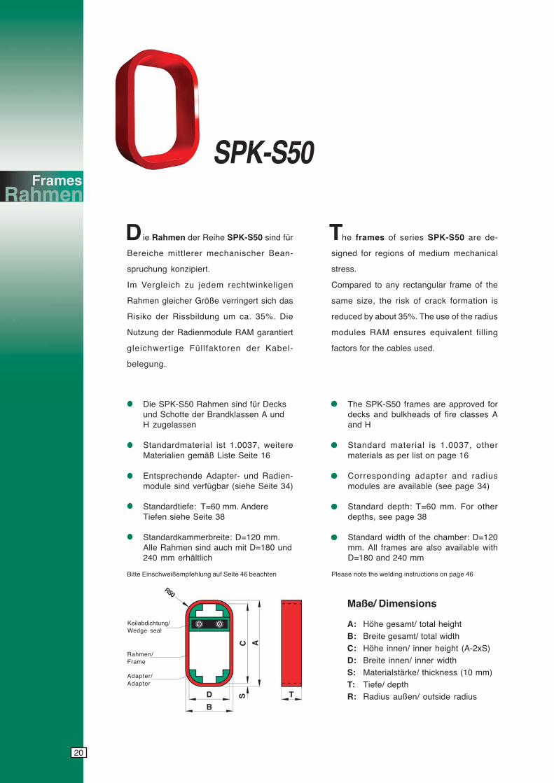
SPK-S50
ie Rahmen der Reihe SPK-S50 sind für
Bereiche mittlerer mechanischer Bean-
spruchung konzipiert.
Im Vergleich zu jedem rechtwinkeligen
Rahmen gleicher Größe verringert sich das
Risiko der Rissbildung um ca. 35%. Die
Nutzung der Radienmodule RAM garantiert
gleichwertige Füllfaktoren der Kabel-
belegung.
he frames of series SPK-S50 are de-
signed for regions of medium mechanical
stress.
Compared to any rectangular frame of the
same size, the risk of crack formation is
reduced by about 35%. The use of the radius
modules RAM ensures equivalent filling
factors for the cables used.
Die SPK-S50 Rahmen sind für Decksund Schotte der Brandklassen A undH zugelassen
Standardmaterial ist 1.0037, weitereMaterialien gemäß Liste Seite 16
Entsprechende Adapter- und Radien-module sind verfügbar (siehe Seite 34)
Standardtiefe: T=60 mm. AndereTiefen siehe Seite 38
Standardkammerbreite: D=120 mm.Alle Rahmen sind auch mit D=180 und240 mm erhältlich
The SPK-S50 frames are approved fordecks and bulkheads of fire classes Aand H
Standard material is 1.0037, othermaterials as per list on page 16
Corresponding adapter and radiusmodules are available (see page 34)
Standard depth: T=60 mm. For otherdepths, see page 38
Standard width of the chamber: D=120mm. All frames are also available withD=180 and 240 mm
Bitte Einschweißempfehlung auf Seite 46 beachten
Keilabdichtung/Wedge seal
Rahmen/Frame
R50
D
B
S T
C A
Adapter/Adapter
Maße/ Dimensions
A: Höhe gesamt/ total height
B: Breite gesamt/ total width
C: Höhe innen/ inner height (A-2xS)D: Breite innen/ inner width
S: Materialstärke/ thickness (10 mm)
T: Tiefe/ depthR: Radius außen/ outside radius
Please note the welding instructions on page 46
D T

21
cyanmagentayellowblack
SPK-S50-2xn 145 145 2.0 3.8 5.6 7.4 9.1 10.9 12.7 14.4 16.2SPK-S50-2+2xn 260 270 3.9 7.9 11.5 15.4 18.5 22.1 25.7 29.1 32.7SPK-S50-2+2+2xn 385 405 5.4 12.0 17.4 23.1 27.9 33.3 38.7 43.8 49.2SPK-S50-2+4xn 320 330 4.4 8.8 12.6 16.5 20.2 24.1 27.9 31.7 35.5SPK-S50-2+6xn 380 390 4.9 9.6 13.8 17.9 21.9 26.1 30.2 34.2 38.4SPK-S50-2+8xn 440 450 5.6 10.5 14.9 19.3 23.6 28.0 32.5 36.8 41.2
SPK-S50-4xn 195 195 2.6 4.7 6.7 8.8 10.8 12.9 14.9 17.0 19.0SPK-S50-4+4xn 380 390 4.9 9.7 13.7 17.9 21.9 26.1 30.1 34.3 38.3SPK-S50-4+4+4xn 565 585 7.2 14.7 20.7 27.0 33.0 39.3 45.3 51.6 57.6SPK-S50-4+6xn 440 450 5.5 10.5 14.9 19.3 23.6 28.1 32.4 36.8 41.2SPK-S50-4+8xn 500 510 6.1 11.4 16.0 20.7 25.3 30.0 34.7 39.4 44.0
SPK-S50-6xn 255 255 3.2 5.5 7.9 10.2 12.5 14.9 17.2 19.5 21.9SPK-S50-6+6xn 500 510 6.1 11.3 16.1 20.7 25.3 30.1 34.7 39.3 44.1SPK-S50-6+6+6xn 745 765 9.0 17.1 24.3 31.2 38.1 45.3 52.2 59.1 66.3SPK-S50-6+8xn 560 570 6.7 12.2 17.2 22.1 27.0 32.0 37.0 41.9 46.9
SPK-S50-8xn 315 315 3.7 6.4 9.0 11.6 14.2 16.8 19.5 22.1 24.7SPK-S50-8+8xn 620 630 7.3 13.1 18.3 23.5 28.7 33.9 39.3 44.5 49.7SPK-S50-8+8+8xn 925 945 10.5 19.8 27.6 35.4 43.2 51.0 59.1 66.9 74.7
n=1 n=2 n=3 n=4 n=5 n=6 n=7 n=8 n=9
B=140 B=270 B=400 B=530 B=660 B=790 B=920 B=1050 B=1180
n=1 n>1
ARahmen/Frames
n= horizontale Kammerzahl; alle Maße in mm
entsprechende Gewichte für Aluminium mAl = mSt x 0,345
andere Kombinationen auf Anfrage
n= horizontal number of chambers; all dimensions in mm
Equivalent weights for aluminium: mAl = mSt x 0.345
other combinations upon request
Beispiele/Examples SPK-S50-2+6 A=380
B=140mSt=4.9kg
SPK-S50-4+4x3 A=390B=400mSt=13.7kg
SizesGrößen
2 4 6 8 6x2 2+6 4+4x3
Maße und Gewichte Dimensions and Weights
Gewicht Stahl/weight steel mSt [kg]
A A
A
A A
A A
B B B B B B B
10
20
22
cyanmagentayellowblack
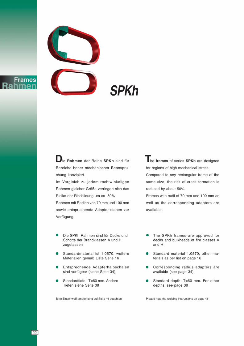
SPKh
Bitte Einschweißempfehlung auf Seite 46 beachten
ie Rahmen der Reihe SPKh sind für
Bereiche hoher mechanischer Beanspru-
chung konzipiert.
Im Vergleich zu jedem rechtwinkeligen
Rahmen gleicher Größe verringert sich das
Risiko der Rissbildung um ca. 50%.
Rahmen mit Radien von 70 mm und 100 mm
sowie entsprechende Adapter stehen zur
Verfügung.
Die SPKh Rahmen sind für Decks undSchotte der Brandklassen A und Hzugelassen
Standardmaterial ist 1.0570, weitereMaterialien gemäß Liste Seite 16
Entsprechende Adapterhalbschalensind verfügbar (siehe Seite 34)
Standardtiefe: T=60 mm. AndereTiefen siehe Seite 38
The SPKh frames are approved fordecks and bulkheads of fire classes Aand H
Standard material 1.0570, other ma-terials as per list on page 16
Corresponding radius adapters areavailable (see page 34)
Standard depth: T=60 mm. For otherdepths, see page 38
he frames of series SPKh are designed
for regions of high mechanical stress.
Compared to any rectangular frame of the
same size, the risk of crack formation is
reduced by about 50%.
Frames with radii of 70 mm and 100 mm as
well as the corresponding adapters are
available.
Please note the welding instructions on page 46
D T
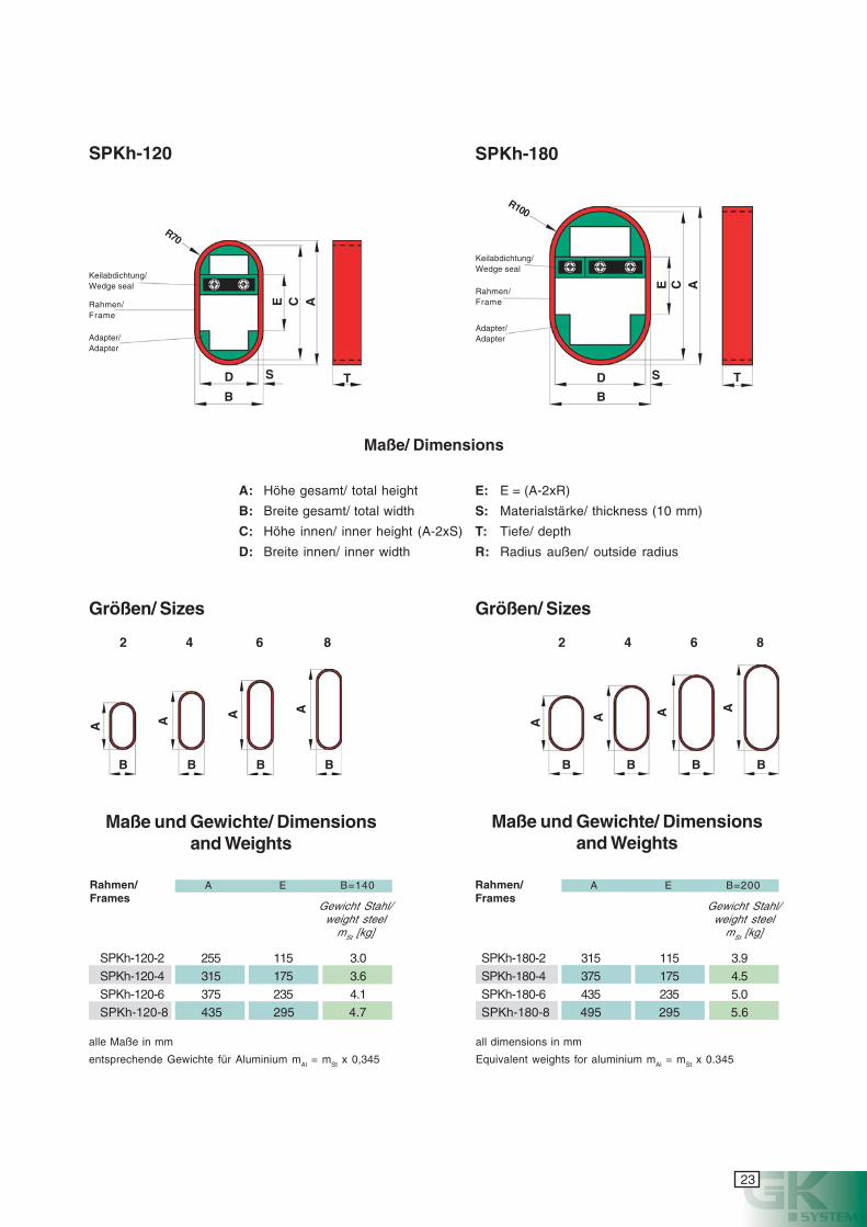
23
cyanmagentayellowblack
SPKh-120-2 255 115 3.0SPKh-120-4 315 175 3.6SPKh-120-6 375 235 4.1SPKh-120-8 435 295 4.7
A E B=140Rahmen/Frames
Gewicht Stahl/weight steel
mSt [kg]
Maße und Gewichte/ Dimensionsand Weights
SPKh-120 SPKh-180
SPKh-180-2 315 115 3.9SPKh-180-4 375 175 4.5SPKh-180-6 435 235 5.0SPKh-180-8 495 295 5.6
Maße und Gewichte/ Dimensionsand Weights
Maße/ Dimensions
A: Höhe gesamt/ total height
B: Breite gesamt/ total width
C: Höhe innen/ inner height (A-2xS)
D: Breite innen/ inner width
E: E = (A-2xR)
S: Materialstärke/ thickness (10 mm)
T: Tiefe/ depth
R: Radius außen/ outside radius
Keilabdichtung/Wedge seal
Rahmen/Frame
Adapter/Adapter
R70
D
B
S T
E A
Keilabdichtung/Wedge seal
Rahmen/Frame
Adapter/Adapter
R100
D
B
S T
E A
Gewicht Stahl/weight steel
mSt [kg]
C
C
alle Maße in mm
entsprechende Gewichte für Aluminium mAl = mSt x 0,345
all dimensions in mm
Equivalent weights for aluminium mAl = mSt x 0.345
A
B
A
B
A
B
A
B
2 4 6 8 2 4 6 8
Größen/ Sizes Größen/ Sizes
A
B
A
B
A
B
A
B
A E B=200Rahmen/Frames
24
cyanmagentayellowblack
er Rahmen Typ SPK findet überall dort
Anwendung, wo keine besonderen me-
chanischen Beanspruchungen auftreten.
Die Keilabdichtung kann frei im Rahmen
positioniert werden.
Die SPK Rahmen sind für Decks undSchotte der Brandklassen A und Hzugelassen
Standardmaterial ist 1.0037, weitereMaterialien gemäß Liste Seite 16
Standardtiefe: T=60 mm. Andere Tiefensiehe Seite 38
Standardkammerbreite: D=120 mm. AlleRahmen sind auch mit D=60, 180 und240 mm erhältlich
he frame type SPK is used wherever no
particular mechanical stresses occur.
The wedge seal can be positioned freely in
the frame.
SPK
Bitte Einschweißempfehlung auf Seite 46 beachten
The SPK frames are approved for decksand bulkheads of fire classes A and H
Standard material is 1.0037, othermaterials as per list on page 16
Standard depth: T=60 mm. For otherdepths, see page 38
Standard width of the chamber: D=120mm. All frames are also available withD=60, 180 and 240 mm
Keilabdichtung/Wedge seal
Rahmen/Frame
R10
D
B
S T
C A
Maße/ Dimensions
A: Höhe gesamt/ total height
B: Breite gesamt/ total width
C: Höhe innen/ inner height (A-2xS)D: Breite innen/ inner width
S: Materialstärke/ thickness (10 mm)
T: Tiefe/ depthR: Radius außen/ outside radius
Please note the welding instructions on page 46
D T
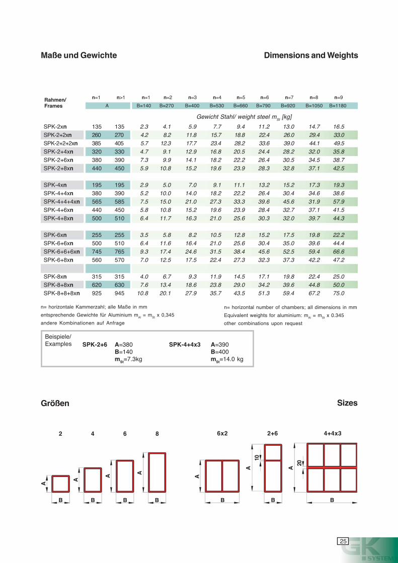
25
cyanmagentayellowblack
SizesGrößen
2 4 6 8 6x2 2+6 4+4x3
n= horizontale Kammerzahl; alle Maße in mm
entsprechende Gewichte für Aluminium mAl = mSt x 0,345
andere Kombinationen auf Anfrage
n= horizontal number of chambers; all dimensions in mm
Equivalent weights for aluminium: mAl = mSt x 0.345
other combinations upon request
Beispiele/Examples SPK-2+6 A=380
B=140mSt=7.3kg
Maße und Gewichte Dimensions and Weights
Rahmen/Frames
SPK-4+4x3 A=390B=400mSt=14.0 kg
A
A
A
B B B B
10
20
A
A
B
A
B
A
B
SPK-2+2xn 260 270 4.2 8.2 11.8 15.7 18.8 22.4 26.0 29.4 33.0SPK-2+2+2xn 385 405 5.7 12.3 17.7 23.4 28.2 33.6 39.0 44.1 49.5SPK-2+4xn 320 330 4.7 9.1 12.9 16.8 20.5 24.4 28.2 32.0 35.8SPK-2+6xn 380 390 7.3 9.9 14.1 18.2 22.2 26.4 30.5 34.5 38.7SPK-2+8xn 440 450 5.9 10.8 15.2 19.6 23.9 28.3 32.8 37.1 42.5
SPK-4xn 195 195 2.9 5.0 7.0 9.1 11.1 13.2 15.2 17.3 19.3SPK-4+4xn 380 390 5.2 10.0 14.0 18.2 22.2 26.4 30.4 34.6 38.6SPK-4+4+4xn 565 585 7.5 15.0 21.0 27.3 33.3 39.6 45.6 31.9 57.9SPK-4+6xn 440 450 5.8 10.8 15.2 19.6 23.9 28.4 32.7 37.1 41.5SPK-4+8xn 500 510 6.4 11.7 16.3 21.0 25.6 30.3 32.0 39.7 44.3
SPK-6xn 255 255 3.5 5.8 8.2 10.5 12.8 15.2 17.5 19.8 22.2SPK-6+6xn 500 510 6.4 11.6 16.4 21.0 25.6 30.4 35.0 39.6 44.4SPK-6+6+6xn 745 765 9.3 17.4 24.6 31.5 38.4 45.6 52.5 59.4 66.6SPK-6+8xn 560 570 7.0 12.5 17.5 22.4 27.3 32.3 37.3 42.2 47.2
SPK-8xn 315 315 4.0 6.7 9.3 11.9 14.5 17.1 19.8 22.4 25.0SPK-8+8xn 620 630 7.6 13.4 18.6 23.8 29.0 34.2 39.6 44.8 50.0
SPK-2xn 135 135 2.3 4.1 5.9 7.7 9.4 11.2 13.0 14.7 16.5
A B=140 B=270 B=400 B=530 B=660 B=790 B=920 B=1050 B=1180
n=1 n>1 n=1 n=2 n=3 n=4 n=5 n=6 n=7 n=8 n=9
Gewicht Stahl/ weight steel mSt [kg]
SPK-8+8+8xn 925 945 10.8 20.1 27.9 35.7 43.5 51.3 59.4 67.2 75.0
26
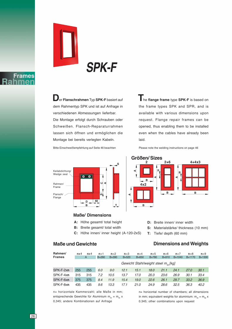
cyanmagentayellowblack
SPK-F
SPK-F-2xn 255 255 6.0 9.0 12.1 15.1 18.0 21.1 24.1 27.0 30.1SPK-F-4xn 315 315 7.2 10.5 13.7 17.0 20.3 23.6 26.9 30.1 33.4SPK-F-6xn 375 375 8.4 11.9 15.4 19.0 22.6 26.1 29.7 33.2 36.9SPK-F-8xn 435 435 9.6 13.3 17.1 21.0 24.9 28.6 32.5 36.3 40.2
n=1 n>1 n=1 n=2 n=3 n=4 n=5 n=6 n=7 n=8 n=9 A B=260 B=390 B=520 B=650 B=780 B=910 B=1040 B=1170 B=1300
Rahmen/Frames
Gewicht Stahl/weight steel mSt [kg]
he flange frame type SPK-F is based on
the frame types SPK and SPR, and is
available with various dimensions upon
request. Flange repair frames can be
opened, thus enabling them to be installed
even when the cables have already been
laid.
Keilabdichtung/Wedge seal
Rahmen/Frame
Flansch/Flange
n= horizontale Kammerzahl; alle Maße in mm;
entsprechende Gewichte für Aluminium mAI = mSt x
0,345; andere Kombinationen auf Anfrage
Maße/ Dimensions
A: Höhe gesamt/ total height
B: Breite gesamt/ total width
C: Höhe innen/ inner height (A-120-2xS)
D: Breite innen/ inner width
S: Materialstärke/ thickness (10 mm)
T: Tiefe/ depth (60 mm)
Maße und Gewichte Dimensions and Weights
2 2+6 4+4x3
4x2
Größen/ Sizes
60DB
S
T
C A
S
B
A
B
A
B
A
B
A
10
20
er Flanschrahmen Typ SPK-F basiert auf
dem Rahmentyp SPK und ist auf Anfrage in
verschiedenen Abmessungen lieferbar.
Die Montage erfolgt durch Schrauben oder
Schweißen. Flansch-Reparaturrahmen
lassen sich öffnen und ermöglichen die
Montage bei bereits verlegten Kabeln.
n= horizontal number of chambers; all dimensions
in mm; equivalent weights for aluminium: mAl = mSt x
0.345; other combinations upon request
D T
Bitte Einschweißempfehlung auf Seite 46 beachten Please note the welding instructions on page 46
27
cyanmagentayellowblack
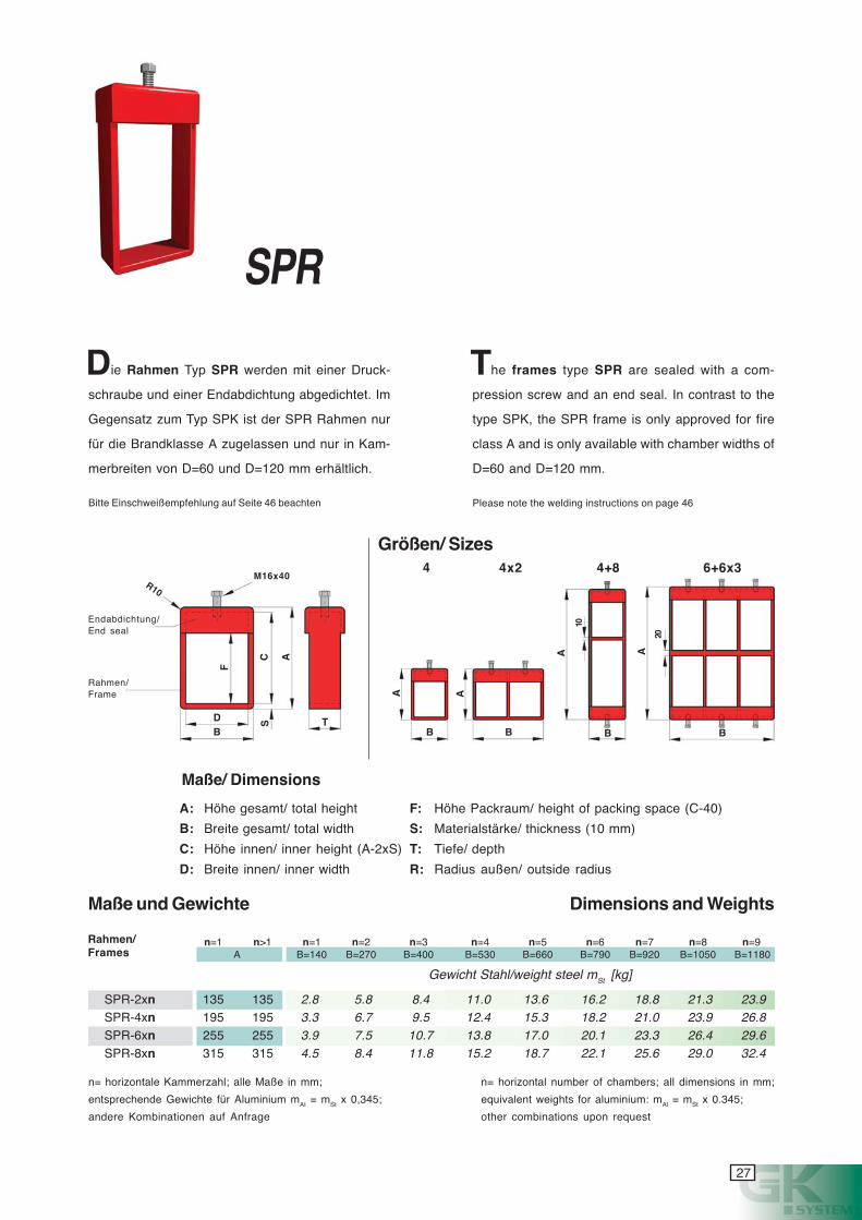
SPR
ie Rahmen Typ SPR werden mit einer Druck-
schraube und einer Endabdichtung abgedichtet. Im
Gegensatz zum Typ SPK ist der SPR Rahmen nur
für die Brandklasse A zugelassen und nur in Kam-
merbreiten von D=60 und D=120 mm erhältlich.
he frames type SPR are sealed with a com-
pression screw and an end seal. In contrast to the
type SPK, the SPR frame is only approved for fire
class A and is only available with chamber widths of
D=60 and D=120 mm.
Maße/ Dimensions
A: Höhe gesamt/ total height
B: Breite gesamt/ total width
C: Höhe innen/ inner height (A-2xS)
D: Breite innen/ inner width
F: Höhe Packraum/ height of packing space (C-40)
S: Materialstärke/ thickness (10 mm)
T: Tiefe/ depth
R: Radius außen/ outside radius
Endabdichtung/End seal
Rahmen/Frame
4 4x2
F
DB
S T
C A
B
A
B
A
B
A
B
A
10
20
M16x40R10
4+8 6+6x3
SPR-2xn 135 135 2.8 5.8 8.4 11.0 13.6 16.2 18.8 21.3 23.9SPR-4xn 195 195 3.3 6.7 9.5 12.4 15.3 18.2 21.0 23.9 26.8SPR-6xn 255 255 3.9 7.5 10.7 13.8 17.0 20.1 23.3 26.4 29.6SPR-8xn 315 315 4.5 8.4 11.8 15.2 18.7 22.1 25.6 29.0 32.4
n=1 n>1 n=1 n=2 n=3 n=4 n=5 n=6 n=7 n=8 n=9A B=140 B=270 B=400 B=530 B=660 B=790 B=920 B=1050 B=1180
Rahmen/Frames
Gewicht Stahl/weight steel mSt [kg]
n= horizontale Kammerzahl; alle Maße in mm;
entsprechende Gewichte für Aluminium mAI = mSt x 0,345;
andere Kombinationen auf Anfrage
Maße und Gewichte Dimensions and Weights
n= horizontal number of chambers; all dimensions in mm;
equivalent weights for aluminium: mAl = mSt x 0.345;
other combinations upon request
Größen/ Sizes
D T
Bitte Einschweißempfehlung auf Seite 46 beachten Please note the welding instructions on page 46
28
cyanmagentayellowblack
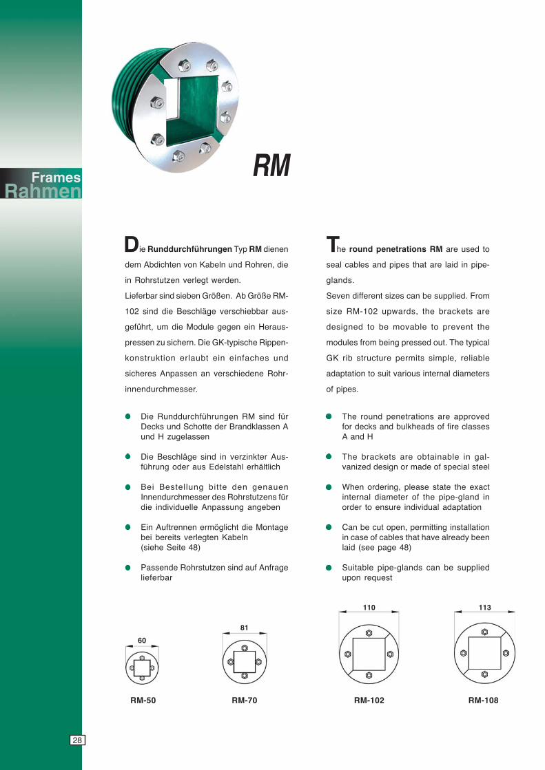
ie Runddurchführungen Typ RM dienen
dem Abdichten von Kabeln und Rohren, die
in Rohrstutzen verlegt werden.
Lieferbar sind sieben Größen. Ab Größe RM-
102 sind die Beschläge verschiebbar aus-
geführt, um die Module gegen ein Heraus-
pressen zu sichern. Die GK-typische Rippen-
konstruktion erlaubt ein einfaches und
sicheres Anpassen an verschiedene Rohr-
innendurchmesser.
Die Runddurchführungen RM sind fürDecks und Schotte der Brandklassen Aund H zugelassen
Die Beschläge sind in verzinkter Aus-führung oder aus Edelstahl erhältlich
Bei Bestellung bitte den genauenInnendurchmesser des Rohrstutzens fürdie individuelle Anpassung angeben
Ein Auftrennen ermöglicht die Montagebei bereits verlegten Kabeln(siehe Seite 48)
Passende Rohrstutzen sind auf Anfragelieferbar
The round penetrations are approvedfor decks and bulkheads of fire classesA and H
The brackets are obtainable in gal-vanized design or made of special steel
When ordering, please state the exactinternal diameter of the pipe-gland inorder to ensure individual adaptation
Can be cut open, permitting installationin case of cables that have already beenlaid (see page 48)
Suitable pipe-glands can be suppliedupon request
he round penetrations RM are used to
seal cables and pipes that are laid in pipe-
glands.
Seven different sizes can be supplied. From
size RM-102 upwards, the brackets are
designed to be movable to prevent the
modules from being pressed out. The typical
GK rib structure permits simple, reliable
adaptation to suit various internal diameters
of pipes.
RM-50 RM-70 RM-102 RM-108
60
81
110 113
RM
D T
29
cyanmagentayellowblack
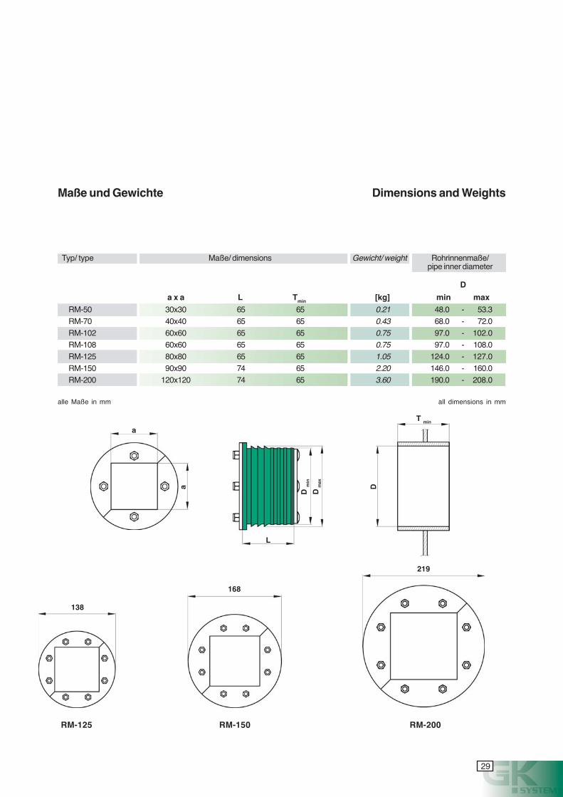
D
a x a L Tmin [kg] min max
RM-50 30x30 65 65 0.21 48.0 - 53.3RM-70 40x40 65 65 0.43 68.0 - 72.0RM-102 60x60 65 65 0.75 97.0 - 102.0RM-108 60x60 65 65 0.75 97.0 - 108.0RM-125 80x80 65 65 1.05 124.0 - 127.0RM-150 90x90 74 65 2.20 146.0 - 160.0RM-200 120x120 74 65 3.60 190.0 - 208.0
Maße und Gewichte Dimensions and Weights
RM-125 RM-150 RM-200
138
219
Typ/ type Maße/ dimensions Gewicht/ weight Rohrinnenmaße/pipe inner diameter
alle Maße in mm all dimensions in mm
168
D m
ax
L
D m
in
T min
Da
a
30
cyanmagentayellowblack
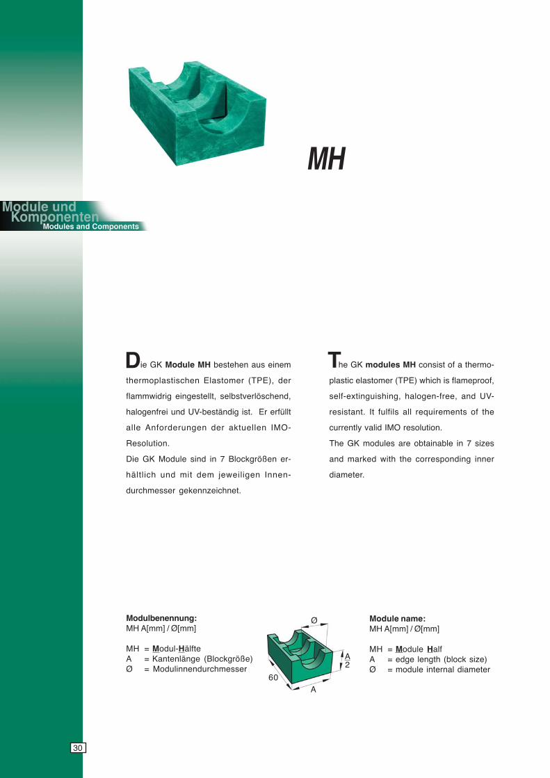
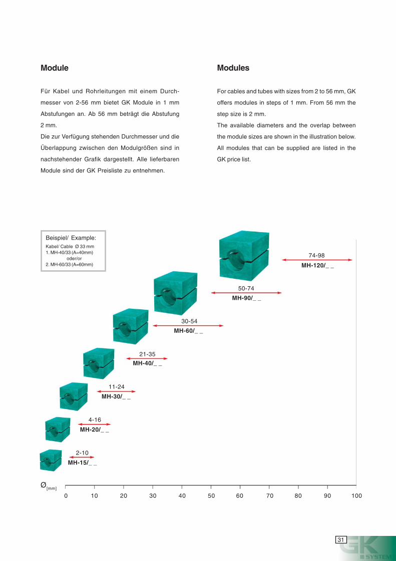
Module name:MH A[mm] / Ø[mm]
MH = Module HalfA = edge length (block size)Ø = module internal diameter
Modulbenennung:MH A[mm] / Ø[mm]
MH = Modul-HälfteA = Kantenlänge (Blockgröße)Ø = Modulinnendurchmesser
Ø
A2
A60
he GK modules MH consist of a thermo-
plastic elastomer (TPE) which is flameproof,
self-extinguishing, halogen-free, and UV-
resistant. It fulfils all requirements of the
currently valid IMO resolution.
The GK modules are obtainable in 7 sizes
and marked with the corresponding inner
diameter.
ie GK Module MH bestehen aus einem
thermoplastischen Elastomer (TPE), der
flammwidrig eingestellt, selbstverlöschend,
halogenfrei und UV-beständig ist. Er erfüllt
alle Anforderungen der aktuellen IMO-
Resolution.
Die GK Module sind in 7 Blockgrößen er-
hältlich und mit dem jeweiligen Innen-
durchmesser gekennzeichnet.
MH
D T
31
cyanmagentayellowblack
MH-15/_ _
MH-20/_ _
MH-30/_ _
MH-40/_ _
MH-60/_ _
MH-90/_ _
74-98
50-74
30-54
21-35
11-24
4-16
2-10
MH-120/_ _
Ø[mm]
Beispiel/ Example:Kabel/ Cable Ø 33 mm1. MH-40/33 (A=40mm)
oder/or2. MH-60/33 (A=60mm)
Module Modules
Für Kabel und Rohrleitungen mit einem Durch-
messer von 2-56 mm bietet GK Module in 1 mm
Abstufungen an. Ab 56 mm beträgt die Abstufung
2.mm.
Die zur Verfügung stehenden Durchmesser und die
Überlappung zwischen den Modulgrößen sind in
nachstehender Grafik dargestellt. Alle lieferbaren
Module sind der GK Preisliste zu entnehmen.
For cables and tubes with sizes from 2 to 56 mm, GK
offers modules in steps of 1 mm. From 56 mm the
step size is 2 mm.
The available diameters and the overlap between
the module sizes are shown in the illustration below.
All modules that can be supplied are listed in the
GK price list.
0 10 20 30 40 50 60 70 80 90 100
32
cyanmagentayellowblack
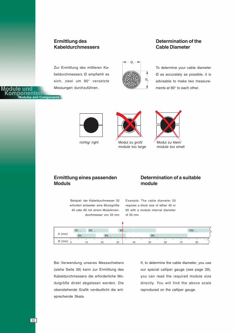
Ø [mm]
Ø1
Ø2
Modul zu groß/module too large
Modul zu klein/module too small
richtig/ right
Ermittlung desKabeldurchmessers
Zur Ermittlung des mittleren Ka-
beldurchmessers Ø empfiehlt es
sich, zwei um 90° versetzte
Messungen durchzuführen.
Determination of theCable Diameter
Ermittlung eines passendenModuls
Determination of a suitablemodule
To determine your cable diameter
Ø as accurately as possible, it is
advisable to make two measure-
ments at 90° to each other.
Example: The cable diameter 33
requires a block size of either 40 or
60 with a module internal diameter
of 33 mm
Bei Verwendung unseres Messschiebers
(siehe Seite 39) kann zur Ermittlung des
Kabeldurchmessers die erforderliche Mo-
dulgröße direkt abgelesen werden. Die
obenstehende Grafik verdeutlicht die ent-
sprechende Skala.
Beispiel: der Kabeldurchmesser 33
erfordert entweder eine Blockgröße
40 oder 60 mit einem Modulinnen-
durchmesser von 33 mm
If, to determine the cable diameter, you use
our special calliper gauge (see page 39),
you can read the required module size
directly. You will f ind the above scale
reproduced on the calliper gauge.
A [mm]
0 10 20 30 40 50 60 70 80
15/_ _ 30/_ _ 60/_ _ 120/_ _
20/_ _ 40/_ _ 90/_ _
33
cyanmagentayellowblack
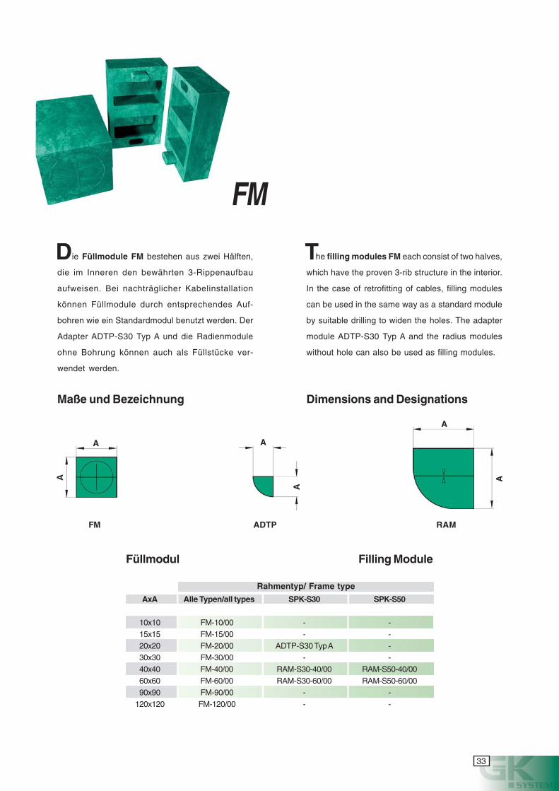
ie Füllmodule FM bestehen aus zwei Hälften,
die im Inneren den bewährten 3-Rippenaufbau
aufweisen. Bei nachträglicher Kabelinstallation
können Füllmodule durch entsprechendes Auf-
bohren wie ein Standardmodul benutzt werden. Der
Adapter ADTP-S30 Typ A und die Radienmodule
ohne Bohrung können auch als Füllstücke ver-
wendet werden.
AxA Alle Typen/all types SPK-S30 SPK-S50
10x10 FM-10/00 - -15x15 FM-15/00 - -20x20 FM-20/00 ADTP-S30 Typ A -30x30 FM-30/00 - -40x40 FM-40/00 RAM-S30-40/00 RAM-S50-40/0060x60 FM-60/00 RAM-S30-60/00 RAM-S50-60/0090x90 FM-90/00 - -
120x120 FM-120/00 - -
A
A
A
A
A
A
FM ADTP RAM
Füllmodul Filling Module
Maße und Bezeichnung Dimensions and Designations
Rahmentyp/ Frame type
he filling modules FM each consist of two halves,
which have the proven 3-rib structure in the interior.
In the case of retrofitting of cables, filling modules
can be used in the same way as a standard module
by suitable drilling to widen the holes. The adapter
module ADTP-S30 Typ A and the radius modules
without hole can also be used as filling modules.
FM
D T
34
cyanmagentayellowblack
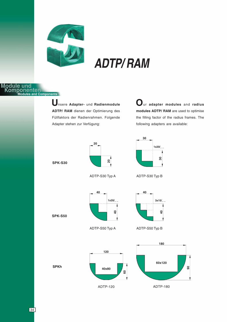
nsere Adapter- und Radienmodule
ADTP/ RAM dienen der Optimierung des
Füllfaktors der Radienrahmen. Folgende
Adapter stehen zur Verfügung:
SPK-S30
SPK-S50
SPKh
ADTP-S30 Typ A
ADTP-S50 Typ B
ur adapter modules and radius
modules ADTP/ RAM are used to optimise
the filling factor of the radius frames. The
following adapters are available:
ADTP-S30 Typ B
ADTP-S50 Typ A
ADTP-180ADTP-120
30
30
40
40
40
40
60
120
90
180
20
20
40x80
60x120
1x20/_ _ 3x15/_ _
1x20/_ _
U O
ADTP/ RAM
35
cyanmagentayellowblack
40
40
60
60
40
40
60
60
RAM-S30-60/_ _ RAM-S50-40/_ _ RAM-S50-60/_ _
RAM-S30-60/_ _
RAM-S30-40/_ _
RAM-S30-40/_ _
RAM-S50-60/_ _
RAM-S50-40/_ _
R 20 R 20 R 40R 40
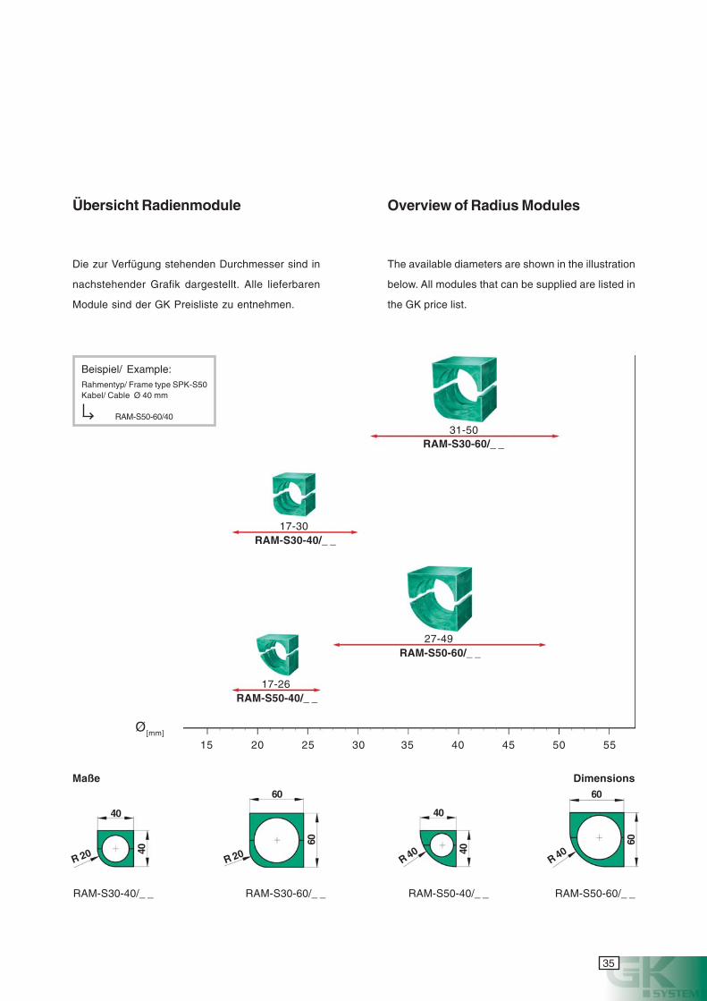
Beispiel/ Example:Rahmentyp/ Frame type SPK-S50Kabel/ Cable Ø 40 mm
RAM-S50-60/40
Ø[mm]
17-26
31-50
17-30
27-49
15 20 25 30 35 40 45 50 55
Die zur Verfügung stehenden Durchmesser sind in
nachstehender Grafik dargestellt. Alle lieferbaren
Module sind der GK Preisliste zu entnehmen.
The available diameters are shown in the illustration
below. All modules that can be supplied are listed in
the GK price list.
Übersicht Radienmodule Overview of Radius Modules
Maße Dimensions
36
cyanmagentayellowblack
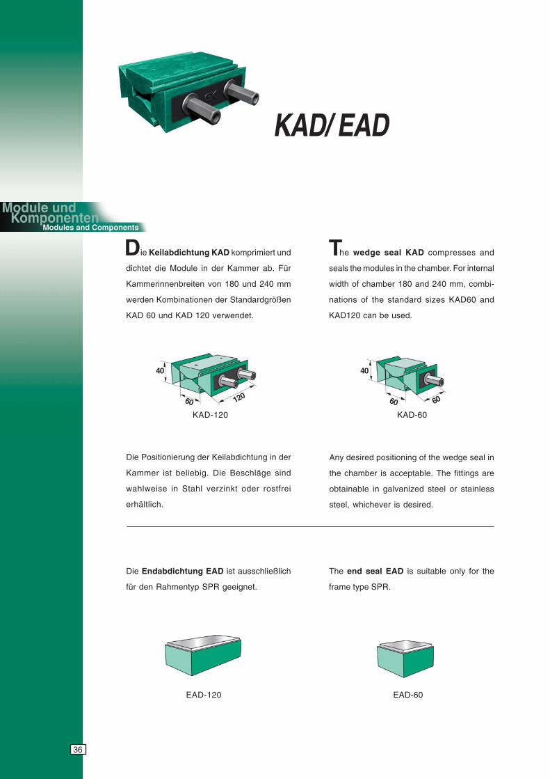
ie Keilabdichtung KAD komprimiert und
dichtet die Module in der Kammer ab. Für
Kammerinnenbreiten von 180 und 240 mm
werden Kombinationen der Standardgrößen
KAD 60 und KAD 120 verwendet.
he wedge seal KAD compresses and
seals the modules in the chamber. For internal
width of chamber 180 and 240 mm, combi-
nations of the standard sizes KAD60 and
KAD120 can be used.
KAD-120
Die Positionierung der Keilabdichtung in der
Kammer ist beliebig. Die Beschläge sind
wahlweise in Stahl verzinkt oder rostfrei
erhältlich.
Any desired positioning of the wedge seal in
the chamber is acceptable. The fittings are
obtainable in galvanized steel or stainless
steel, whichever is desired.
Die Endabdichtung EAD ist ausschließlich
für den Rahmentyp SPR geeignet.
The end seal EAD is suitable only for the
frame type SPR.
EAD-120
12060
40
KAD/ EAD
6060
40
KAD-60
EAD-60
D T
37
cyanmagentayellowblack
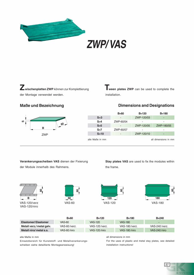
VAS-120/verz
B=60 B=120 B=180S=3 - ZWP-120/03 -S=4 ZWP-60/04 - -S=5 - ZWP-120/05 ZWP-180/05S=7 ZWP-60/07 - -S=10 - ZWP-120/10 -ZWP
alle Maße in mm
Einsatzbereich für Kunststoff- und Metallverankerungs-
scheiben siehe detaillierte Montageanweisung!
Verankerungsscheiben VAS dienen der Fixierung
der Module innerhalb des Rahmens.
B=60 B=120 B=180 B=240Elastomer/ Elastomer VAS-60 VAS-120 VAS-180 -Metall verz./ metal galv. VAS-60 /verz. VAS-120 /verz. VAS-180 /verz. VAS-240 /verz.Metall niro/ metal s.s. VAS-60 /niro VAS-120 /niro VAS-180 /niro VAS-240 /niro
B60
S
B
60
60
60
120
60
180
60
VAS-120/verzVAS-120/niro
VAS-60 VAS-120 VAS-180
wischenplatten ZWP können zur Komplettierung
der Montage verwendet werden.
Maße und Bezeichnung Dimensions and Designations
alle Maße in mm all dimensions in mm
Stay plates VAS are used to fix the modules within
the frame.
all dimensions in mm
For the uses of plastic and metal stay plates, see detailed
installation instructions!
ween plates ZWP can be used to complete the
installation.
ZWP/ VAS
Z T
38
cyanmagentayellowblack
Sonderlösungen
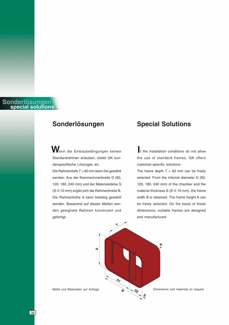
enn die Einbaubedingungen keinen
Standardrahmen erlauben, bietet GK kun-
denspezifische Lösungen an:
Die Rahmentiefe T > 60 mm kann frei gewählt
werden. Aus der Kammerinnenbreite D (60,
120, 180, 240 mm) und der Materialstärke S
(S ⊕ 10 mm) ergibt sich die Rahmenbreite B.
Die Rahmenhöhe A kann beliebig gewählt
werden. Basierend auf diesen Maßen wer-
den geeignete Rahmen konstruiert und
gefertigt.
W
Special Solutions
T
B
A
D1
R
f the installation conditions do not allow
the use of standard frames, GK offers
customer-specific solutions:
The frame depth T > 60 mm can be freely
selected. From the internal diameter D (60,
120, 180, 240 mm) of the chamber and the
material thickness S (S ⊕ 10 mm), the frame
width B is obtained. The frame height A can
be freely selected. On the basis of these
dimensions, suitable frames are designed
and manufactured.
I
D2S
Maße und Materialien auf Anfrage Dimensions and materials on request
39
cyanmagentayellowblack
Zubehör
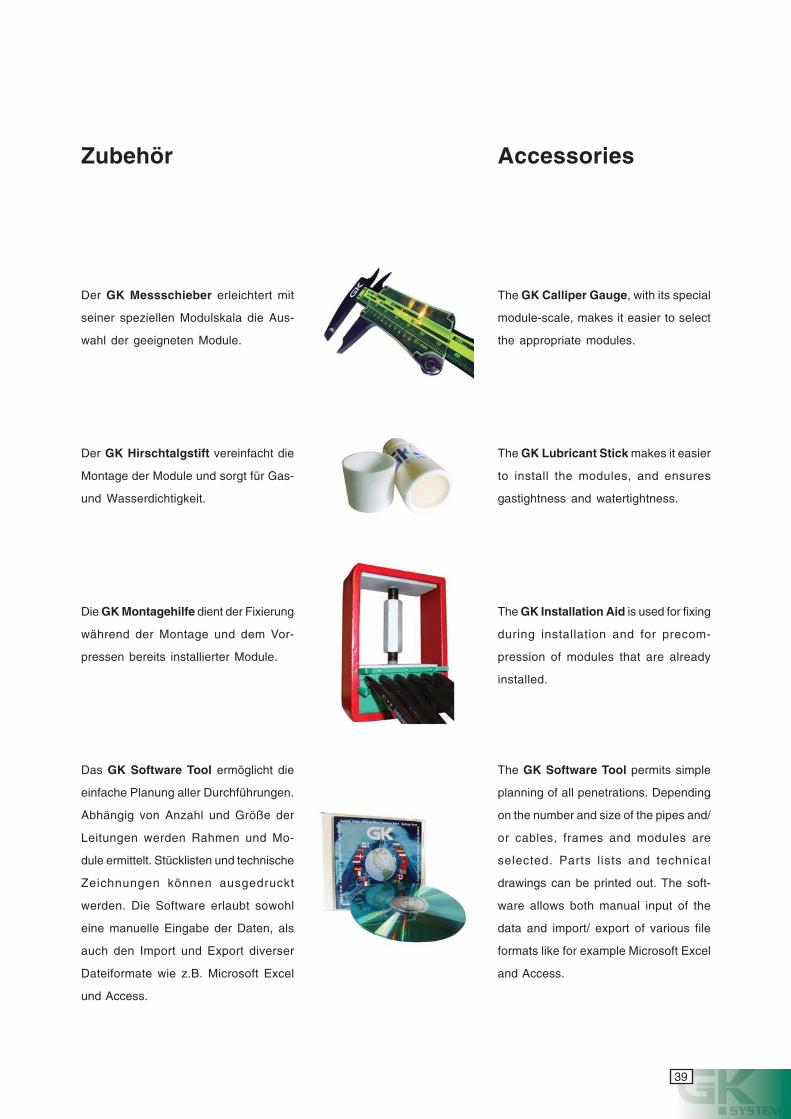
Die GK Montagehilfe dient der Fixierung
während der Montage und dem Vor-
pressen bereits installierter Module.
Der GK Hirschtalgstift vereinfacht die
Montage der Module und sorgt für Gas-
und Wasserdichtigkeit.
Das GK Software Tool ermöglicht die
einfache Planung aller Durchführungen.
Abhängig von Anzahl und Größe der
Leitungen werden Rahmen und Mo-
dule ermittelt. Stücklisten und technische
Zeichnungen können ausgedruckt
werden. Die Software erlaubt sowohl
eine manuelle Eingabe der Daten, als
auch den Import und Export diverser
Dateiformate wie z.B. Microsoft Excel
und Access.
Der GK Messschieber erleichtert mit
seiner speziellen Modulskala die Aus-
wahl der geeigneten Module.
Accessories
The GK Installation Aid is used for fixing
during installation and for precom-
pression of modules that are already
installed.
The GK Lubricant Stick makes it easier
to install the modules, and ensures
gastightness and watertightness.
The GK Software Tool permits simple
planning of all penetrations. Depending
on the number and size of the pipes and/
or cables, frames and modules are
selected. Parts lists and technical
drawings can be printed out. The soft-
ware allows both manual input of the
data and import/ export of various file
formats like for example Microsoft Excel
and Access.
The GK Calliper Gauge, with its special
module-scale, makes it easier to select
the appropriate modules.
40
cyanmagentayellowblack
EMV-System
as GK EMV* System kommt überall dort
zum Einsatz, wo sensible Elektronik vor
elektromagnetischen Einflüssen geschützt
werden muß.
Elektromagnetische Störungen können z.B.
durch Blitzschlag, Funkwellen oder fremd-
induzierte Spannungen hervorgerufen
werden. Wirksamen Schutz vor diesen
Störungen leistet nur ein System,
welches zum einen eine elek-
tromagnetisch undurchdring-
liche Barriere darstellt und
zum anderen eine wirksame
Erdung fremdinduzierter
Spannungen herbeiführt.
Das GK EMV System gewähr-
leistet diese Eigenschaften
aufgrund seiner speziellen Kon-
struktion idealerweise in einem System.
Wie das GK Standardsystem besteht auch
das GK EMV System aus einem Rahmen,
einem Dichtungselement und Modulen zur
Abdichtung der Kabel. Es verfügt daher über
die gleichen mechanischen Vorteile.
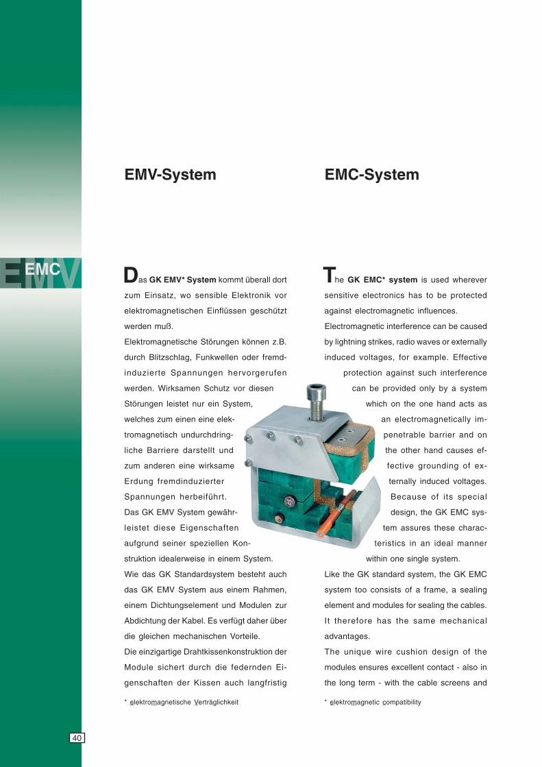
Die einzigartige Drahtkissenkonstruktion der
Module sichert durch die federnden Ei-
genschaften der Kissen auch langfristig
EMC-System
he GK EMC* system is used wherever
sensitive electronics has to be protected
against electromagnetic influences.
Electromagnetic interference can be caused
by lightning strikes, radio waves or externally
induced voltages, for example. Effective
protection against such interference
can be provided only by a system
which on the one hand acts as
an electromagnetically im-
penetrable barrier and on
the other hand causes ef-
fective grounding of ex-
ternally induced voltages.
Because of its special
design, the GK EMC sys-
tem assures these charac-
teristics in an ideal manner
within one single system.
Like the GK standard system, the GK EMC
system too consists of a frame, a sealing
element and modules for sealing the cables.
It therefore has the same mechanical
advantages.
The unique wire cushion design of the
modules ensures excellent contact - also in
the long term - with the cable screens and
D T
* elektromagnetische Verträglichkeit * elektromagnetic compatibility
41
cyanmagentayellowblack
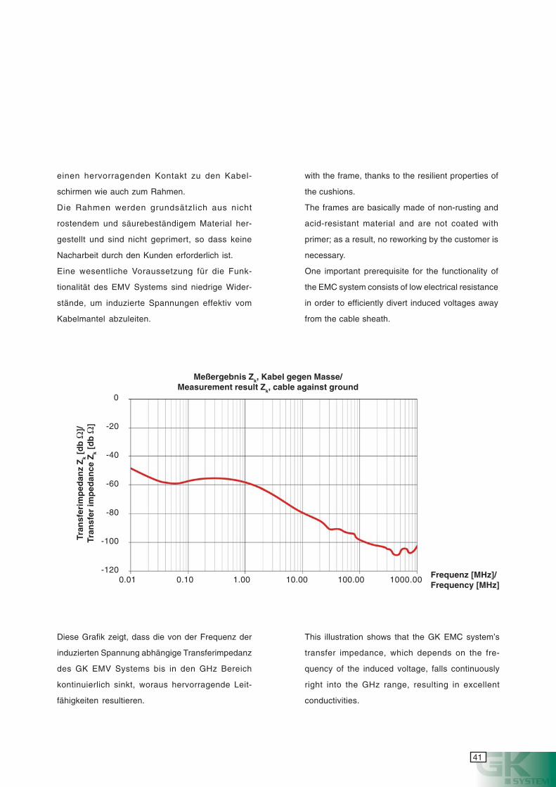
Diese Grafik zeigt, dass die von der Frequenz der
induzierten Spannung abhängige Transferimpedanz
des GK EMV Systems bis in den GHz Bereich
kontinuierlich sinkt, woraus hervorragende Leit-
fähigkeiten resultieren.
einen hervorragenden Kontakt zu den Kabel-
schirmen wie auch zum Rahmen.
Die Rahmen werden grundsätzlich aus nicht
rostendem und säurebeständigem Material her-
gestellt und sind nicht geprimert, so dass keine
Nacharbeit durch den Kunden erforderlich ist.
Eine wesentliche Voraussetzung für die Funk-
tionalität des EMV Systems sind niedrige Wider-
stände, um induzierte Spannungen effektiv vom
Kabelmantel abzuleiten.
with the frame, thanks to the resilient properties of
the cushions.
The frames are basically made of non-rusting and
acid-resistant material and are not coated with
primer; as a result, no reworking by the customer is
necessary.
One important prerequisite for the functionality of
the EMC system consists of low electrical resistance
in order to efficiently divert induced voltages away
from the cable sheath.
0
-20
-40
-60
-80
-100
-1200.01 0.10 1.00 10.00 100.00 1000.00
Meßergebnis Zk, Kabel gegen Masse/Measurement result Zk, cable against ground
Tran
sfer
imp
edan
z Z
k [d
b Ω
]/Tr
ansf
er im
ped
ance
Zk
[db
Ω]
This illustration shows that the GK EMC system’s
transfer impedance, which depends on the fre-
quency of the induced voltage, falls continuously
right into the GHz range, resulting in excellent
conductivities.
Frequenz [MHz]/Frequency [MHz]
42
cyanmagentayellowblack
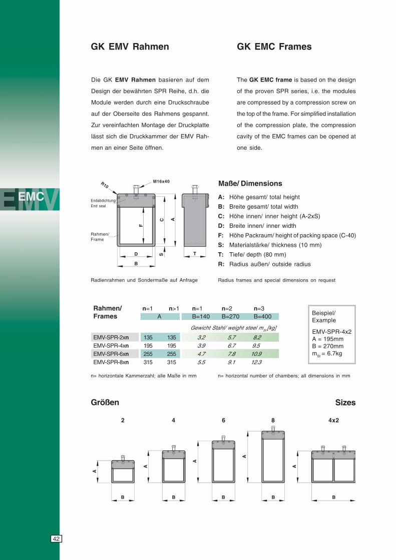
Die GK EMV Rahmen basieren auf dem
Design der bewährten SPR Reihe, d.h. die
Module werden durch eine Druckschraube
auf der Oberseite des Rahmens gespannt.
Zur vereinfachten Montage der Druckplatte
lässt sich die Druckkammer der EMV Rah-
men an einer Seite öffnen.
GK EMV Rahmen
Rahmen/ n=1 n>1 n=1 n=2 n=3Frames A B=140 B=270 B=400
Gewicht Stahl/ weight steel mSt [kg]
EMV-SPR-2xn 135 135 3.2 5.7 8.2EMV-SPR-4xn 195 195 3.9 6.7 9.5EMV-SPR-6xn 255 255 4.7 7.8 10.9EMV-SPR-8xn 315 315 5.5 9.1 12.3
Maße/ Dimensions
A: Höhe gesamt/ total height
B: Breite gesamt/ total width
C: Höhe innen/ inner height (A-2xS)
D: Breite innen/ inner width
F: Höhe Packraum/ height of packing space (C-40)
S: Materialstärke/ thickness (10 mm)
T: Tiefe/ depth (80 mm)
R: Radius außen/ outside radius
Größen
n= horizontale Kammerzahl; alle Maße in mm
Radius frames and special dimensions on request
Beispiel/Example
EMV-SPR-4x2A = 195mmB = 270mmmSt = 6.7kg
GK EMC Frames
Sizes
Endabdichtung/End seal
Rahmen/Frame
F
D
B
S T
C A
M16x40R10
B
A
B
A
B
A
B
A
B
A
4x28642
The GK EMC frame is based on the design
of the proven SPR series, i.e. the modules
are compressed by a compression screw on
the top of the frame. For simplified installation
of the compression plate, the compression
cavity of the EMC frames can be opened at
one side.
Radienrahmen und Sondermaße auf Anfrage
n= horizontal number of chambers; all dimensions in mm
43
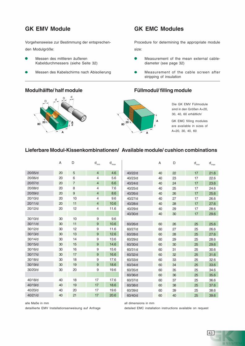
cyanmagentayellowblack
A
Vorgehensweise zur Bestimmung der entsprechen-
den Modulgröße:
GK EMV Module GK EMC Modules
Messen des mittleren äußerenKabeldurchmessers (siehe Seite 32)
Messen des Kabelschirms nach Abisolierung
Procedure for determining the appropriate module
size:
Measurement of the mean external cable-diameter (see page 32)
Measurement of the cable screen afterstripping of insulation
A D dmin dmax
20/05/d 20 5 4 4.620/06/d 20 6 4 5.620/07/d 20 7 4 6.620/08/d 20 8 4 7.620/09/d 20 9 4 8.620/10/d 20 10 4 9.620/11/d 20 11 4 10.620/12/d 20 12 4 11.6
30/10/d 30 10 9 9.630/11/d 30 11 9 10.630/12/d 30 12 9 11.630/13/d 30 13 9 12.630/14/d 30 14 9 13.630/15/d 30 15 9 14.630/16/d 30 16 9 15.630/17/d 30 17 9 16.630/18/d 30 18 9 17.630/19/d 30 19 9 18.630/20/d 30 20 9 19.6
40/18/d 40 18 17 17.640/19/d 40 19 17 18.640/20/d 40 20 17 19.640/21/d 40 21 17 20.6
Lieferbare Modul-Kissenkombinationen/ Available module/ cushion combinations
Die GK EMV Füllmodule
sind in den Größen A=20,
30, 40, 60 erhältlich/
alle Maße in mm
detaillierte EMV Installationsanweisung auf Anfrage
all dimensions in mm
detailed EMC installation instructions available on request
Modulhälfte/ half module Füllmodul/ filling module
A D dmin dmax
40/22/d 40 22 17 21.640/23/d 40 23 17 22.640/24/d 40 24 17 23.640/25/d 40 25 17 24.640/26/d 40 26 17 25.640/27/d 40 27 17 26.640/28/d 40 28 17 27.640/29/d 40 29 17 28.640/30/d 40 30 17 29.6
60/26/d 60 26 25 25.660/27/d 60 27 25 26.660/28/d 60 28 25 27.660/29/d 60 29 25 28.660/30/d 60 30 25 29.660/31/d 60 31 25 30.660/32/d 60 32 25 31.660/33/d 60 33 25 32.660/34/d 60 34 25 33.660/35/d 60 35 25 34.660/36/d 60 36 25 35.660/37/d 60 37 25 36.660/38/d 60 38 25 37.660/39/d 60 39 25 38.660/40/d 60 40 25 39.6
A
8020
2
Dd
8020 GK EMC filling modules
are available in sizes of
A=20, 30, 40, 60
A
A
D d

44
cyanmagentayellowblack
45
cyanmagentayellowblack
46
cyanmagentayellowblack
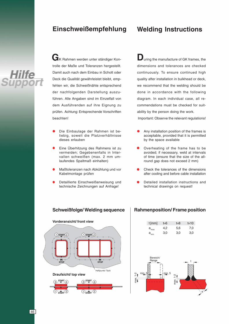
Einschweißempfehlung
K Rahmen werden unter ständiger Kon-
trolle der Maße und Toleranzen hergestellt.
Damit auch nach dem Einbau in Schott oder
Deck die Qualität gewährleistet bleibt, emp-
fehlen wir, die Schweißnähte entsprechend
der nachfolgenden Darstellung auszu-
führen. Alle Angaben sind im Einzelfall von
dem Ausführenden auf ihre Eignung zu
prüfen. Achtung: Entsprechende Vorschriften
beachten!
Die Einbaulage der Rahmen ist be-liebig, soweit die Platzverhältnissedieses erlauben
Eine Überhitzung des Rahmens ist zuvermeiden; Gegebenenfalls in Inter-vallen schweißen (max. 2 mm um-laufendes Spaltmaß einhalten)
Maßtoleranzen nach Abkühlung und vorKabelmontage prüfen
Detaillierte Einschweißanweisung undtechnische Zeichnungen auf Anfrage!
uring the manufacture of GK frames, the
dimensions and tolerances are checked
continuously. To ensure continued high
quality after installation in bulkhead or deck,
we recommend that the welding should be
done in accordance with the following
diagram. In each individual case, all re-
commendations must be checked for suit-
ability by the person doing the work.
Important: Observe the relevant regulations!
t [mm] t=6 t=8 t=10amax 4,2 5,6 7,0amin 3,0 3,0 3,0
Any installation position of the frames isacceptable, provided that it is permittedby the space available
Overheating of the frame has to beavoided; if necessary, weld at intervalsof time (ensure that the size of the all-round gap does not exceed 2 mm)
Check the tolerances of the dimensionsafter cooling and before cable installation
Detailed installation instructions andtechnical drawings on request!
1 2 1 2START START
STOP STOP
START START
START START1 2 1 2
3 4 3 4
Heftpunkt/ Tack
Bereich/Range t
a
max
. 1-2
max
. 1-2 min. 5 min. 5
Welding Instructions
G D
Schweißfolge/ Welding sequence
Vorderansicht/ front view
Draufsicht/ top view
Rahmenposition/ Frame position
47
cyanmagentayellowblack
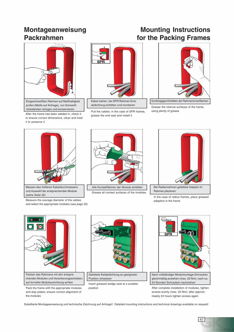
MontageanweisungPackrahmen
Eingeschweißten Rahmen auf Maßhaltigkeitprüfen (Maße auf Anfrage), von Schweiß-rückständen reinigen und konservieren
Kabel ziehen, bei SPR Rahmen End-abdichtung einfetten und montieren
Großzügiges Einfetten der Rahmeninnenflächen
Messen des mittleren Kabeldurchmessersund Auswahl der entsprechenden Module(siehe Seite 32)
Bei Radienrahmen gefettete Adapter imRahmen plazieren
Alle Kontaktflächen der Module einfetten
Packen des Rahmens mit den entspre-chenden Modulen und Verankerungsscheiben;auf korrekte Modulausrichtung achten
Nach vollständiger Modulmontage Schraubengleichmäßig anziehen (max. 20 Nm); nach ca.24 Stunden Schrauben nachziehen
Gefettete Keilabdichtung an geeigneterPosition einsetzen
Pull the cables; in the case of SPR frames,grease the end seal and install it
Grease the internal surfaces of the frame,using plenty of grease
Measure the average diameter of the cablesand select the appropriate modules (see page 32)
Grease all contact surfaces of the modules
In the case of radius frames, place greasedadapters in the frame
Pack the frame with the appropriate modulesand stay plates; ensure correct alignment ofthe modules
Insert greased wedge seal at a suitable
position After complete installation of modules, tightenscrews evenly (max. 20 Nm); after approxi-
mately 24 hours tighten screws again
Mounting Instructionsfor the Packing Frames
After the frame has been welded in, check itto ensure correct dimensions, clean and treatit to preserve it
Detaillierte Montageanweisung und technische Zeichnung auf Anfrage!/ Detailed mounting instructions and technical drawings available on request!
48
cyanmagentayellowblack
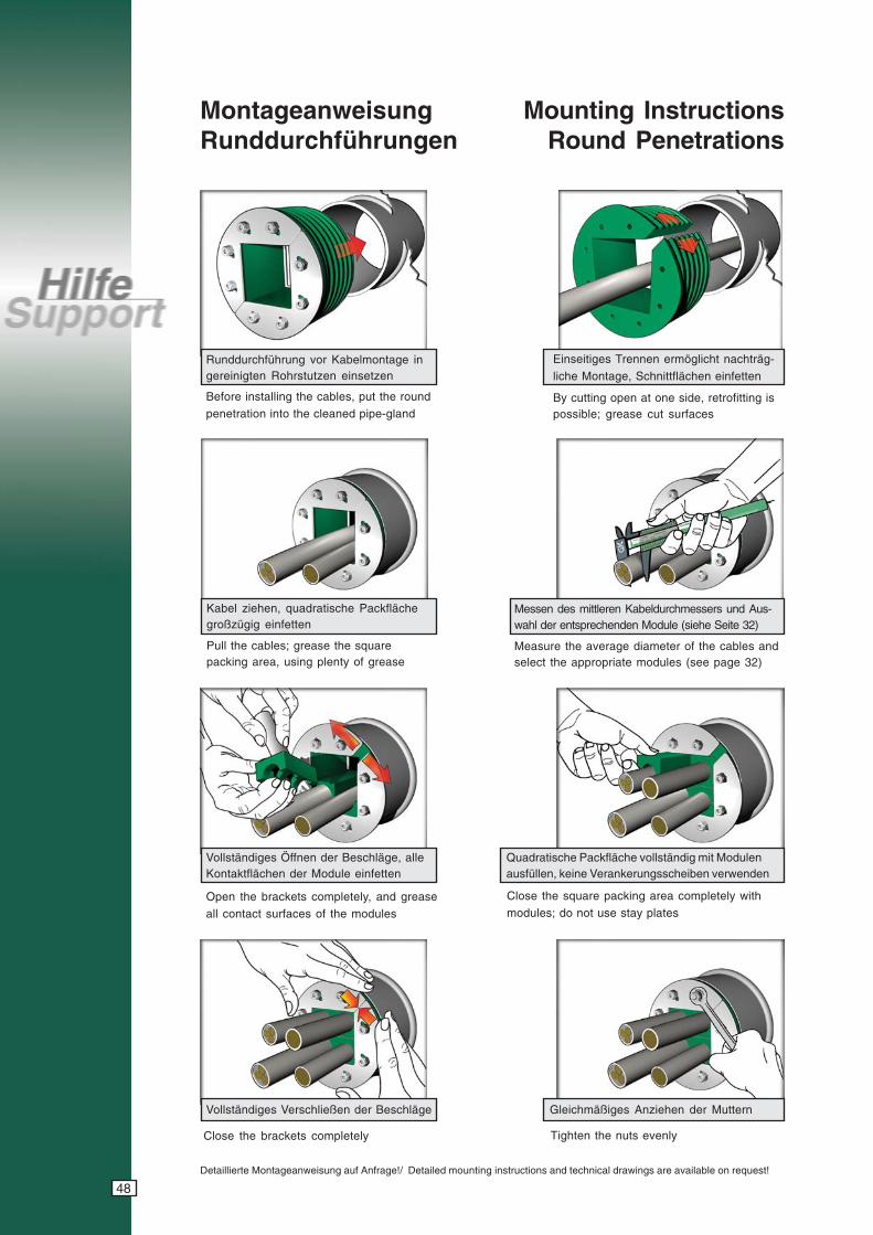
MontageanweisungRunddurchführungen
Runddurchführung vor Kabelmontage ingereinigten Rohrstutzen einsetzen
Messen des mittleren Kabeldurchmessers und Aus-wahl der entsprechenden Module (siehe Seite 32)
Quadratische Packfläche vollständig mit Modulenausfüllen, keine Verankerungsscheiben verwenden
Gleichmäßiges Anziehen der Muttern
Before installing the cables, put the round
penetration into the cleaned pipe-gland
Measure the average diameter of the cables andselect the appropriate modules (see page 32)
Close the square packing area completely with
modules; do not use stay plates
Tighten the nuts evenly
Mounting InstructionsRound Penetrations
Vollständiges Öffnen der Beschläge, alleKontaktflächen der Module einfetten
Vollständiges Verschließen der Beschläge
Open the brackets completely, and grease
all contact surfaces of the modules
Close the brackets completely
Einseitiges Trennen ermöglicht nachträg-
liche Montage, Schnittflächen einfetten
By cutting open at one side, retrofitting ispossible; grease cut surfaces
Kabel ziehen, quadratische Packflächegroßzügig einfetten
Pull the cables; grease the squarepacking area, using plenty of grease
Detaillierte Montageanweisung auf Anfrage!/ Detailed mounting instructions and technical drawings are available on request!
49
cyanmagentayellowblack
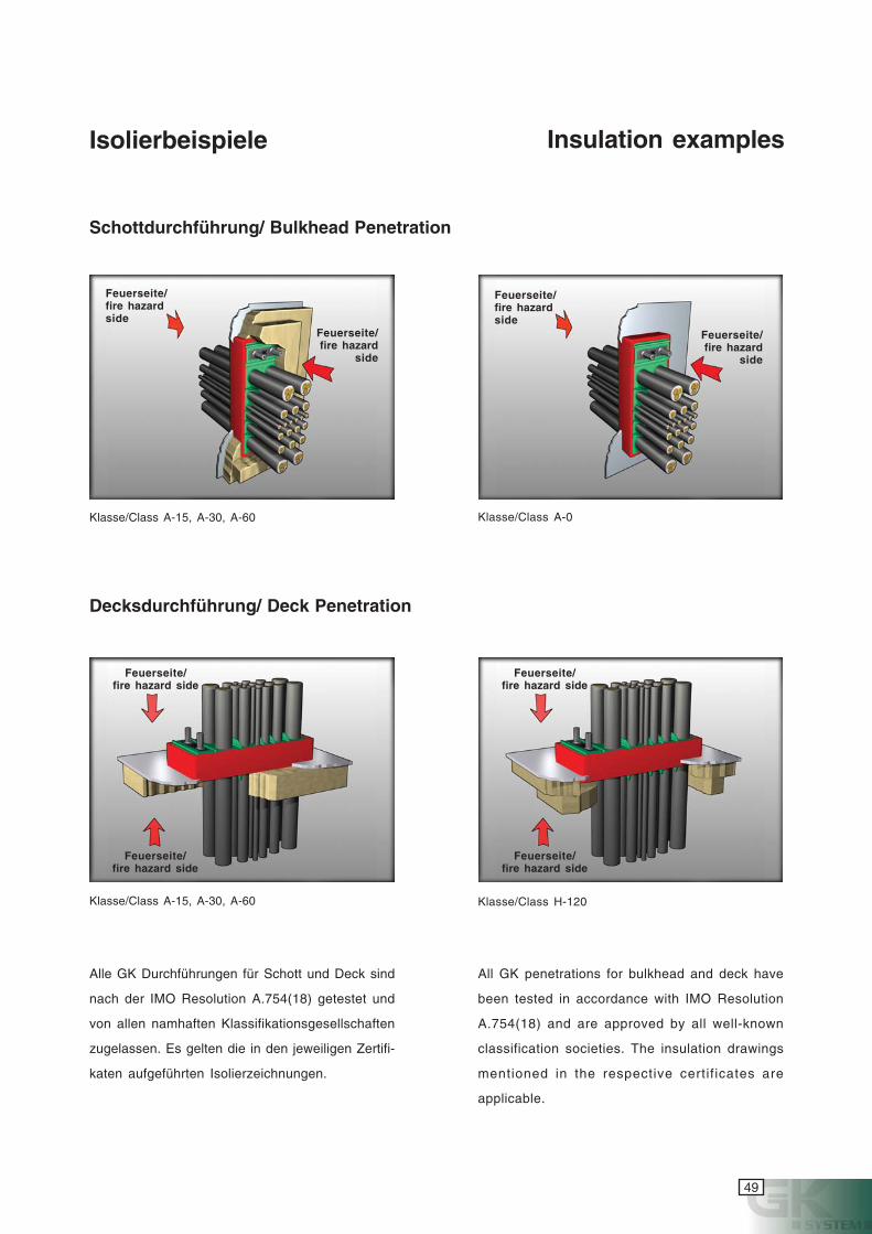
Isolierbeispiele Insulation examples
Feuerseite/fire hazardside
Feuerseite/fire hazard
side
Feuerseite/fire hazard side
Feuerseite/fire hazard side
Feuerseite/fire hazardside
Feuerseite/fire hazard
side
Feuerseite/fire hazard side
Feuerseite/fire hazard side
Klasse/Class A-15, A-30, A-60 Klasse/Class A-0
Klasse/Class A-15, A-30, A-60
Alle GK Durchführungen für Schott und Deck sind
nach der IMO Resolution A.754(18) getestet und
von allen namhaften Klassifikationsgesellschaften
zugelassen. Es gelten die in den jeweiligen Zertifi-
katen aufgeführten Isolierzeichnungen.
All GK penetrations for bulkhead and deck have
been tested in accordance with IMO Resolution
A.754(18) and are approved by all well-known
classification societies. The insulation drawings
mentioned in the respective certif icates are
applicable.
Schottdurchführung/ Bulkhead Penetration
Decksdurchführung/ Deck Penetration
Klasse/Class H-120
50
cyanmagentayellowblack
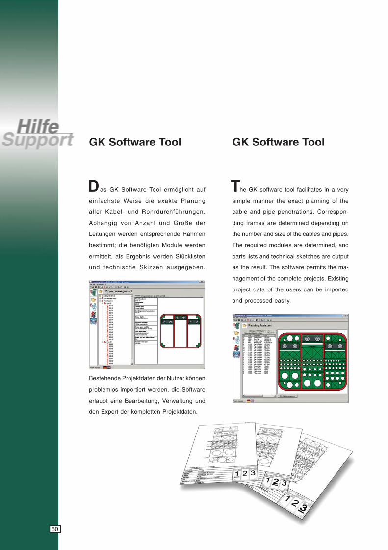
GK Software Tool
as GK Software Tool ermöglicht auf
einfachste Weise die exakte Planung
aller Kabel- und Rohrdurchführungen.
Abhängig von Anzahl und Größe der
Leitungen werden entsprechende Rahmen
bestimmt; die benötigten Module werden
ermittelt, als Ergebnis werden Stücklisten
und technische Skizzen ausgegeben.
D T
GK Software Tool
Bestehende Projektdaten der Nutzer können
problemlos importiert werden, die Software
erlaubt eine Bearbeitung, Verwaltung und
den Export der kompletten Projektdaten.
he GK software tool facilitates in a very
simple manner the exact planning of the
cable and pipe penetrations. Correspon-
ding frames are determined depending on
the number and size of the cables and pipes.
The required modules are determined, and
parts lists and technical sketches are output
as the result. The software permits the ma-
nagement of the complete projects. Existing
project data of the users can be imported
and processed easily.
51
cyanmagentayellowblack
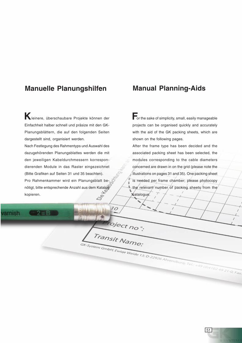
Manuelle Planungshilfen
leinere, überschaubare Projekte können der
Einfachheit halber schnell und präsize mit den GK-
Planungsblättern, die auf den folgenden Seiten
dargestellt sind, organisiert werden.
Nach Festlegung des Rahmentyps und Auswahl des
dazugehörenden Planungsblattes werden die mit
den jeweiligen Kabeldurchmessern korrespon-
dierenden Module in das Raster eingezeichnet
(Bitte Grafiken auf Seiten 31 und 35 beachten).
Pro Rahmenkammer wird ein Planungsblatt be-
nötigt, bitte entsprechende Anzahl aus dem Katalog
kopieren.
or the sake of simplicity, small, easily manageable
projects can be organised quickly and accurately
with the aid of the GK packing sheets, which are
shown on the following pages.
After the frame type has been decided and the
associated packing sheet has been selected, the
modules corresponding to the cable diameters
concerned are drawn in on the grid (please note the
illustrations on pages 31 and 35). One packing sheet
is needed per frame chamber; please photocopy
the relevant number of packing sheets from the
catalogue.
K
Manual Planning-Aids
F
52
cyanmagentayellowblack
Project no°: Date:
Transit Name: Type: SPK-S30-
GK-System GmbH; Ewige Weide 13; D-22926 Ahrensburg; Tel.: +49 (0)4102 49 21-0; Fax: -79; eMail: [email protected]; www.gk-system.com
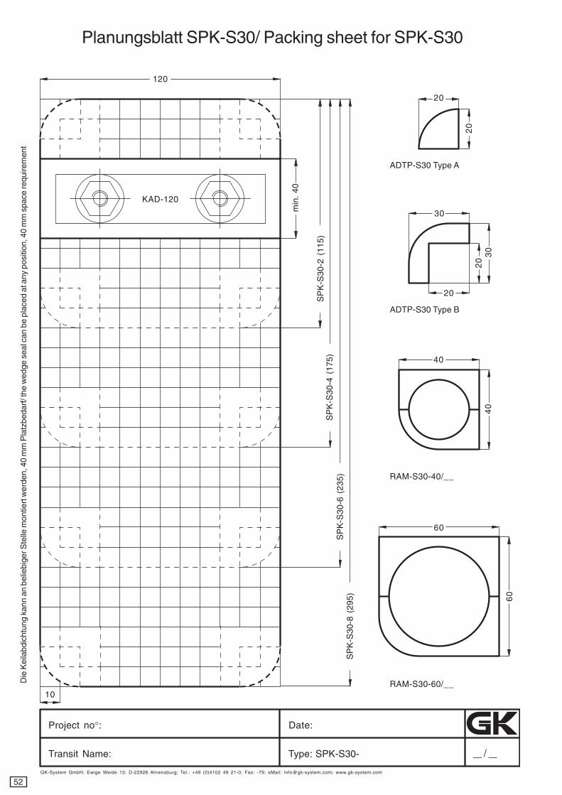
120
10
20
20
30
20
20
30
40
40
60
60
min
. 40
ADTP-S30 Type A
ADTP-S30 Type B
RAM-S30-40/__
RAM-S30-60/__
SP
K-S
30-2
(11
5)S
PK
-S30
-4 (
175)
SP
K-S
30-6
(23
5)S
PK
-S30
-8 (
295)
Die
Kei
labd
icht
ung
kann
an
belie
bige
r Ste
lle m
ontie
rt w
erde
n, 4
0 m
m P
latz
beda
rf/ t
he w
edge
sea
l can
be
plac
ed a
t any
pos
ition
, 40
mm
spa
ce re
quire
men
t
Planungsblatt SPK-S30/ Packing sheet for SPK-S30
KAD-120
53
cyanmagentayellowblack
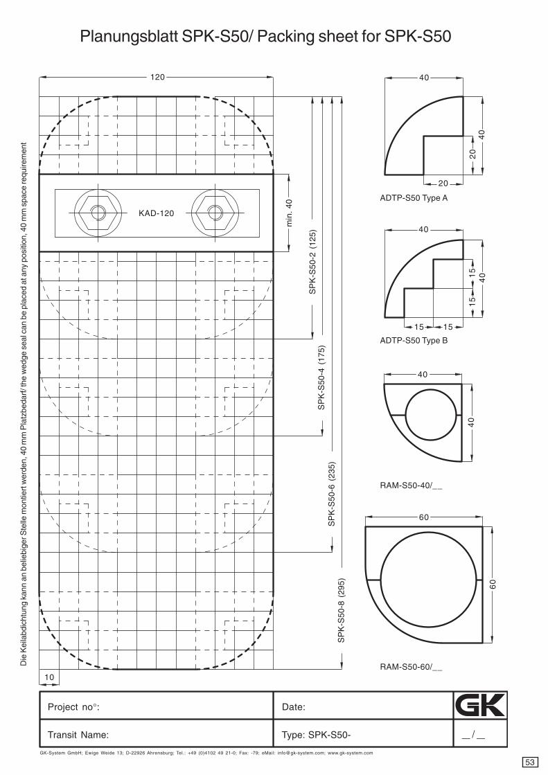
Project no°: Date:
Transit Name: Type: SPK-S50-
GK-System GmbH; Ewige Weide 13; D-22926 Ahrensburg; Tel.: +49 (0)4102 49 21-0; Fax: -79; eMail: [email protected]; www.gk-system.com
KAD-120
ADTP-S50 Type A
ADTP-S50 Type B
RAM-S50-40/__
RAM-S50-60/__Die
Kei
labd
icht
ung
kann
an
belie
bige
r Ste
lle m
ontie
rt w
erde
n, 4
0 m
m P
latz
beda
rf/ t
he w
edge
sea
l can
be
plac
ed a
t any
pos
ition
, 40
mm
spa
ce re
quire
men
t
Planungsblatt SPK-S50/ Packing sheet for SPK-S50
120
min
. 40
SP
K-S
50-2
(12
5)S
PK
-S50
-4 (
175)
SP
K-S
50-6
(23
5)S
PK
-S50
-8 (
295)
10
40
40
40
40
15
40
40
60
60
20
20
15
15
15
54
cyanmagentayellowblack
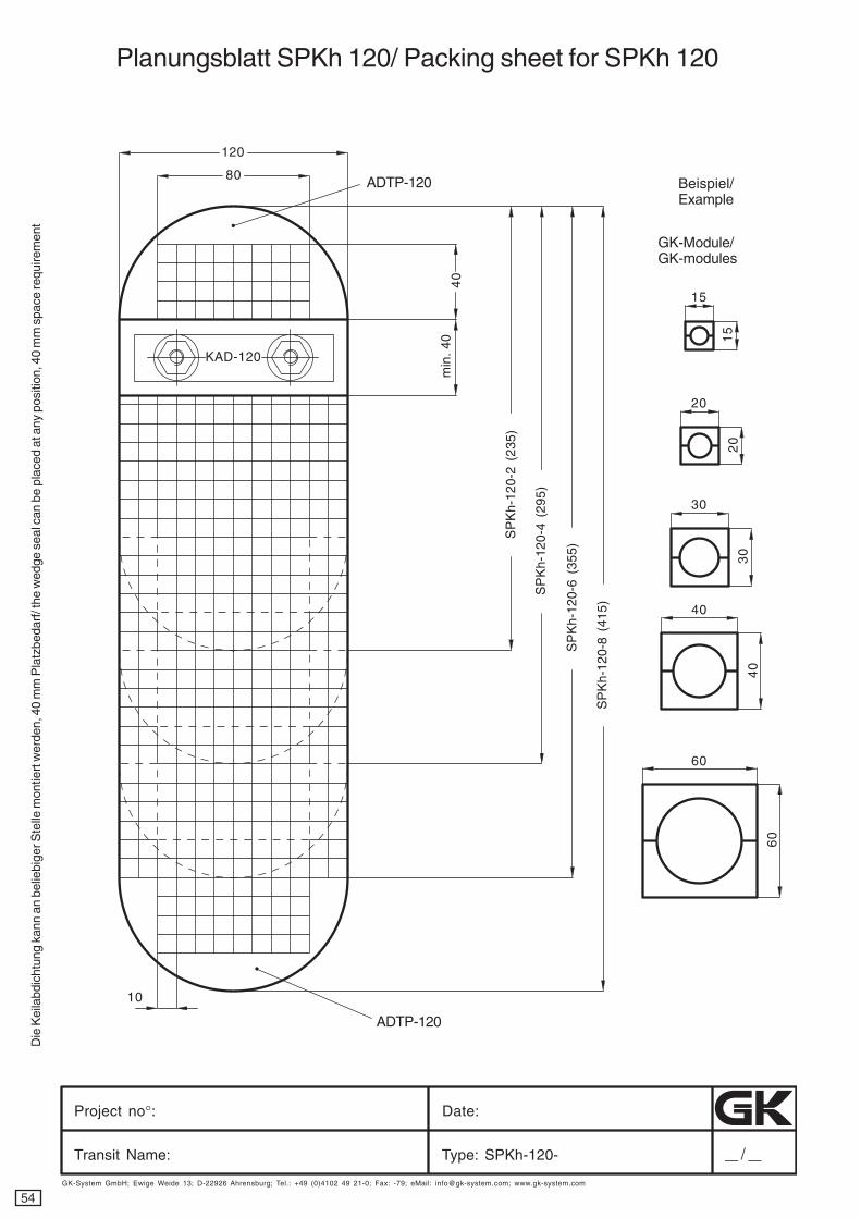
Planungsblatt SPKh 120/ Packing sheet for SPKh 120
Project no°: Date:
Transit Name: Type: SPKh-120-
GK-System GmbH; Ewige Weide 13; D-22926 Ahrensburg; Tel.: +49 (0)4102 49 21-0; Fax: -79; eMail: [email protected]; www.gk-system.com
120
min
. 40
SP
Kh-
120-
2 (2
35)
10
15
15
80 ADTP-120
40
SP
Kh-
120-
4 (2
95)
SP
Kh-
120-
6 (3
55)
SP
Kh-
120-
8 (4
15)
ADTP-120
Beispiel/Example
GK-Module/GK-modules
20
20
30
30
40
40
606
0
Die
Kei
labd
icht
ung
kann
an
belie
bige
r Ste
lle m
ontie
rt w
erde
n, 4
0 m
m P
latz
beda
rf/ t
he w
edge
sea
l can
be
plac
ed a
t any
pos
ition
, 40
mm
spa
ce re
quire
men
t
KAD-120
55
cyanmagentayellowblack
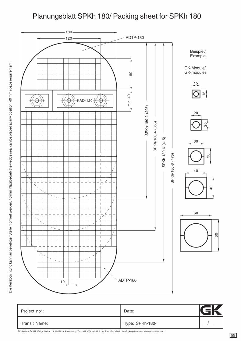
Planungsblatt SPKh 180/ Packing sheet for SPKh 180
Project no°: Date:
Transit Name: Type: SPKh-180-
GK-System GmbH; Ewige Weide 13; D-22926 Ahrensburg; Tel.: +49 (0)4102 49 21-0; Fax: -79; eMail: [email protected]; www.gk-system.com
120
min
. 40
10
15
15
Beispiel/Example
GK-Module/GK-modules
20
20
30
30
40
40
606
0
180
ADTP-180
60
SP
Kh-
180-
2 (2
95)
SP
Kh-
180-
4 (3
55)
SP
Kh-
180-
6 (4
15)
SP
Kh-
180-
8 (4
75)
ADTP-180
Die
Kei
labd
icht
ung
kann
an
belie
bige
r Ste
lle m
ontie
rt w
erde
n, 4
0 m
m P
latz
beda
rf/ t
he w
edge
sea
l can
be
plac
ed a
t any
pos
ition
, 40
mm
spa
ce re
quire
men
t
KAD-120
56
cyanmagentayellowblack
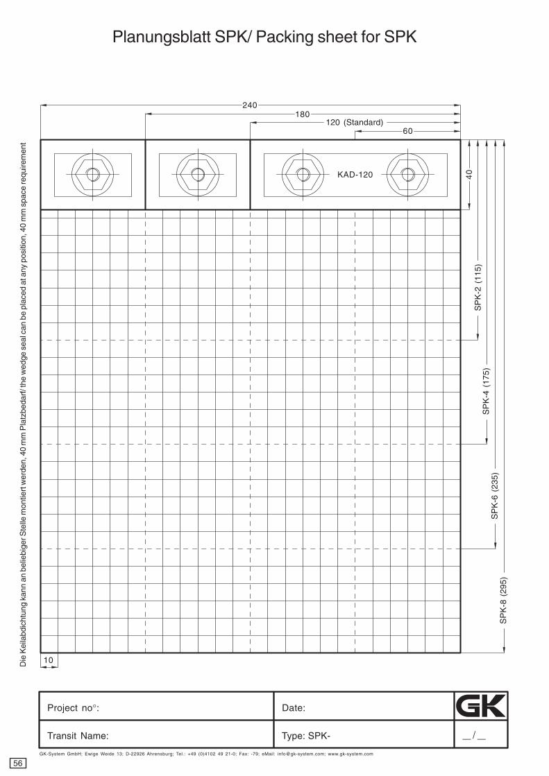
Planungsblatt SPK/ Packing sheet for SPK
Project no°: Date:
Transit Name: Type: SPK-
GK-System GmbH; Ewige Weide 13; D-22926 Ahrensburg; Tel.: +49 (0)4102 49 21-0; Fax: -79; eMail: [email protected]; www.gk-system.com
40
10
180
SP
K-2
(11
5)
240
120 (Standard)60
SP
K-4
(17
5)S
PK
-6 (
235)
SP
K-8
(29
5)
Die
Kei
labd
icht
ung
kann
an
belie
bige
r Ste
lle m
ontie
rt w
erde
n, 4
0 m
m P
latz
beda
rf/ t
he w
edge
sea
l can
be
plac
ed a
t any
pos
ition
, 40
mm
spa
ce re
quire
men
t
KAD-120
57
cyanmagentayellowblack
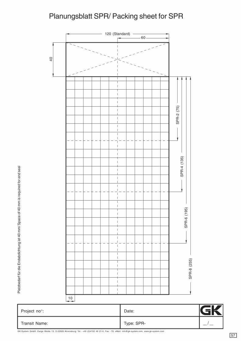
Planungsblatt SPR/ Packing sheet for SPR
Project no°: Date:
Transit Name: Type: SPR-
GK-System GmbH; Ewige Weide 13; D-22926 Ahrensburg; Tel.: +49 (0)4102 49 21-0; Fax: -79; eMail: [email protected]; www.gk-system.com
10
SP
R-2
(75
)
120 (Standard)60
SP
R-8
(25
5)
SP
R-4
(13
5)S
PR
-6 (
195)
40
Pla
tzbe
darf
für d
ie E
ndab
dich
tung
ist 4
0 m
m/ S
pace
of 4
0 m
m is
requ
ired
for e
nd s
eal
58
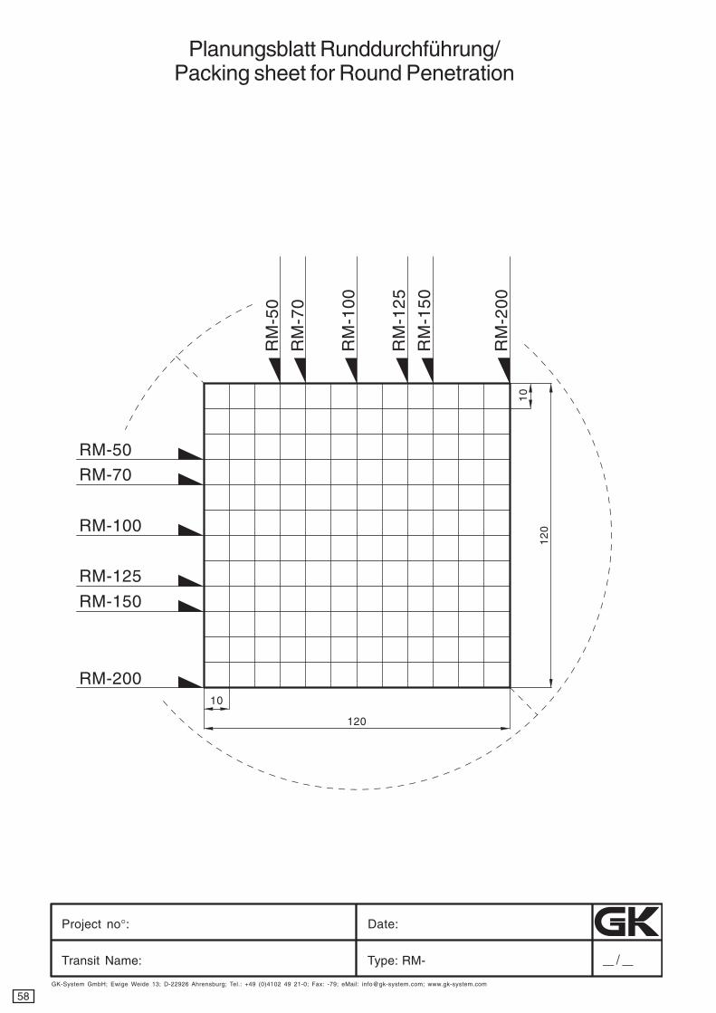
cyanmagentayellowblack
Project no°: Date:
Transit Name: Type: RM-
GK-System GmbH; Ewige Weide 13; D-22926 Ahrensburg; Tel.: +49 (0)4102 49 21-0; Fax: -79; eMail: [email protected]; www.gk-system.com
10
120
10
12
0
RM-50
RM-70
RM-100
RM-125
RM-150
RM-200
RM
-50
RM
-70
RM
-10
0
RM
-12
5
RM
-15
0
RM
-20
0
Planungsblatt Runddurchführung/Packing sheet for Round Penetration
GK-System GmbH Ewige Weide 13 22926 Ahrensburg/GermanyTel. +49 (0) 41 02 - 49 21 - 0 Fax +49 (0) 41 02 - 49 21 - 79
www.gk-system.com [email protected] of the Kaefer Group
devreser se kats im d na s egn ah c la cinh cet /n etlah eb rov neg nur edn
Ä eh csinh cet000.6
300 2/7w
ww /
RbG
m aCdro
N :gnutlats eG dnu n oitpezn o
Ke d.
macdron.