Embed Size (px)
Citation preview
A E R Z E N E R M A S C H I N E N F A B R I K
G M B H
AERZEN
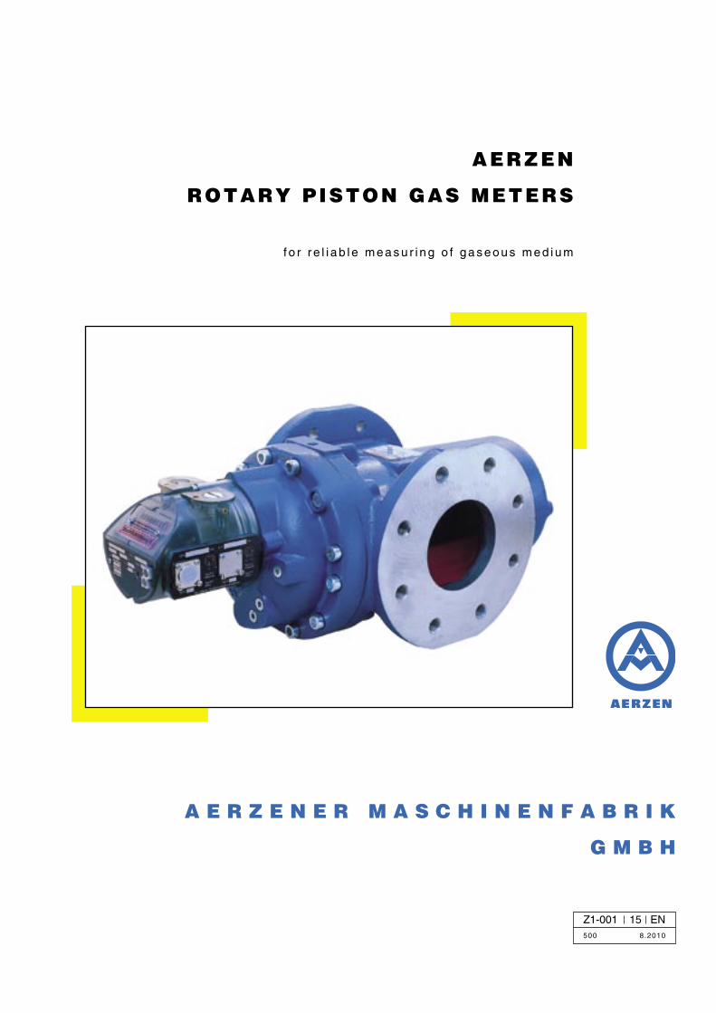
ROTARY PISTON GAS METERS
f o r r e l i a b l e m e a s u r i n g o f g a s e o u s m e d i u m
Z1-001 15 EN500 8.2010
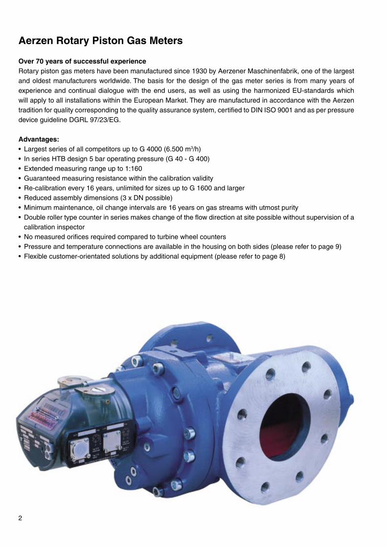
Aerzen Rotary Piston Gas Meters
Over 70 years of successful experienceRotary piston gas meters have been manufactured since 1930 by Aerzener Maschinenfabrik, one of the largest and oldest manufacturers worldwide. The basis for the design of the gas meter series is from many years of experience and continual dialogue with the end users, as well as using the harmonized EU-standards which will apply to all installations within the European Market. They are manufactured in accordance with the Aerzen tradition for quality corresponding to the quality assurance system, certified to DIN ISO 9001 and as per pressure device guideline DGRL 97/23/EG.
Advantages:• Largest series of all competitors up to G 4000 (6.500 m3/h)• In series HTB design 5 bar operating pressure (G 40 - G 400)• Extended measuring range up to 1:160• Guaranteed measuring resistance within the calibration validity• Re-calibration every 16 years, unlimited for sizes up to G 1600 and larger• Reduced assembly dimensions (3 x DN possible)• Minimum maintenance, oil change intervals are 16 years on gas streams with utmost purity• Double roller type counter in series makes change of the flow direction at site possible without supervision of a
calibration inspector• No measured orifices required compared to turbine wheel counters• Pressure and temperature connections are available in the housing on both sides (please refer to page 9)• Flexible customer-orientated solutions by additional equipment (please refer to page 8)
2
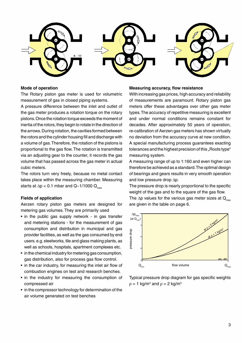
Measuring accuracy, flow resistanceWith increasing gas prices, high accuracy and reliability of measurements are paramount. Rotary piston gas meters offer these advantages over other gas meter types. The accuracy of repetitive measuring is excellent and under normal conditions remains constant for decades. After approximately 50 years of operation, re-calibration of Aerzen gas meters has shown virtually no deviation from the accuracy curve at new condition. A special manufacturing process guarantees exacting tolerances and the highest precision of this „Roots type“ measuring system. A measuring range of up to 1:160 and even higher can therefore be achieved as a standard. The optimal design of bearings and gears results in very smooth operation and low pressure drop ∆p.The pressure drop is nearly proportional to the specific weight of the gas and to the square of the gas flow. The ∆p values for the various gas meter sizes at Qmax are given in the table on page 6.
Typical pressure drop diagram for gas specific weights ρ = 1 kg/m3 and ρ = 2 kg/m3.
Mode of operationThe Rotary piston gas meter is used for volumetric measurement of gas in closed piping systems. A pressure difference between the inlet and outlet of the gas meter produces a rotation torque on the rotary pistons. Once the rotation torque exceeds the moment of inertia of the rotors, they begin to rotate in the direction of the arrows. During rotation, the cavities formed between the rotors and the cylinder housing fill and discharge with a volume of gas. Therefore, the rotation of the pistons is proportional to the gas flow. The rotation is transmitted via an adjusting gear to the counter, it records the gas volume that has passed across the gas meter in actual cubic meters. The rotors turn very freely, because no metal contact takes place within the measuring chamber. Measuring starts at ∆p < 0.1 mbar and Q~1/1000 Qmax
Fields of applicationAerzen rotary piston gas meters are designed for metering gas volumes. They are primarily used• in the public gas supply network - in gas transfer
and metering stations - for the measurement of gas consumption and distribution in municipal and gas provider facilities, as well as the gas consumed by end users. e.g. steelworks, tile and glass making plants, as well as schools, hospitals, apartment complexes etc.
• in the chemical industry for metering gas consumption, gas distribution, also for process gas flow control.
• in the car industry, for measuring the inlet air flow of combustion engines on test and research benches.
• in the industry for measuring the consumption of compressed air
• in the compressor technology for determination of the air volume generated on test benches
3
at ρ = 2 kg
/m3
at ρ = 1 kg/m3
∆pmax
(at Qmax)
pres
sure
dro
p
QmaxQminflow volume
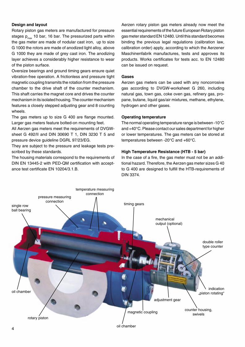
Design and layoutRotary piston gas meters are manufactured for pressure stages pmax 10 bar, 16 bar. The pressurized parts within the gas meter are made of nodular cast iron, up to size G 1000 the rotors are made of anodized light alloy, above G 1000 they are made of grey cast iron. The anodizing layer achieves a considerably higher resistance to wear of the piston surface.Oversize bearings and ground timing gears ensure quiet vibration-free operation. A frictionless and pressure tight magnetic coupling transmits the rotation from the pressure chamber to the drive shaft of the counter mechanism. This shaft carries the magnet core and drives the counter mechanism in its isolated housing. The counter mechanism features a closely stepped adjusting gear and 8 counting wheels.The gas meters up to size G 400 are flange mounted. Larger gas meters feature bolted-on mounting feet. All Aerzen gas meters meet the requirements of DVGW-sheet G 492/II and DIN 30690 T 1, DIN 3230 T 5 and pressure device guideline DGRL 97/23/EG. They are subject to the pressure and leakage tests pre-scribed by these standards. The housing materials correspond to the requirements of DIN EN 13445-2 with PED-QM certification with accept-ance test certificate EN 10204/3.1.B.
Aerzen rotary piston gas meters already now meet the essential requirements of the future European Rotary piston gas meter standard EN 12480. Until this standard becomes binding the previous legal regulations (calibration law, calibration order) apply, according to which the Aerzener Maschinenfabrik manufactures, tests and approves its products. Works certificates for tests acc. to EN 12480 can be issued on request.
GasesAerzen gas meters can be used with any noncorrosive gas according to DVGW-worksheet G 260, including natural gas, town gas, coke oven gas, refinery gas, pro-pane, butane, liquid gas/air mixtures, methane, ethylene, hydrogen and other gases.
Operating temperatureThe normal operating temperature range is between -10°C and +40°C. Please contact our sales department for higher or lower temperatures. The gas meters can be stored at temperatures between -20°C and +60°C.
High Temperature Resistance (HTB - 5 bar)In the case of a fire, the gas meter must not be an addi-tional hazard. Therefore, the Aerzen gas meter sizes G 40 to G 400 are designed to fulfill the HTB-requirements of DIN 3374.
rotary piston
timing gears
temperature measuring connection
pressure measuring connection
single row ball bearing
magnetic coupling
adjustment gear
counter housing, swivels
mechanical output (optional)
double roller type counter
4oil chamber
indication „piston rotating“oil chamber
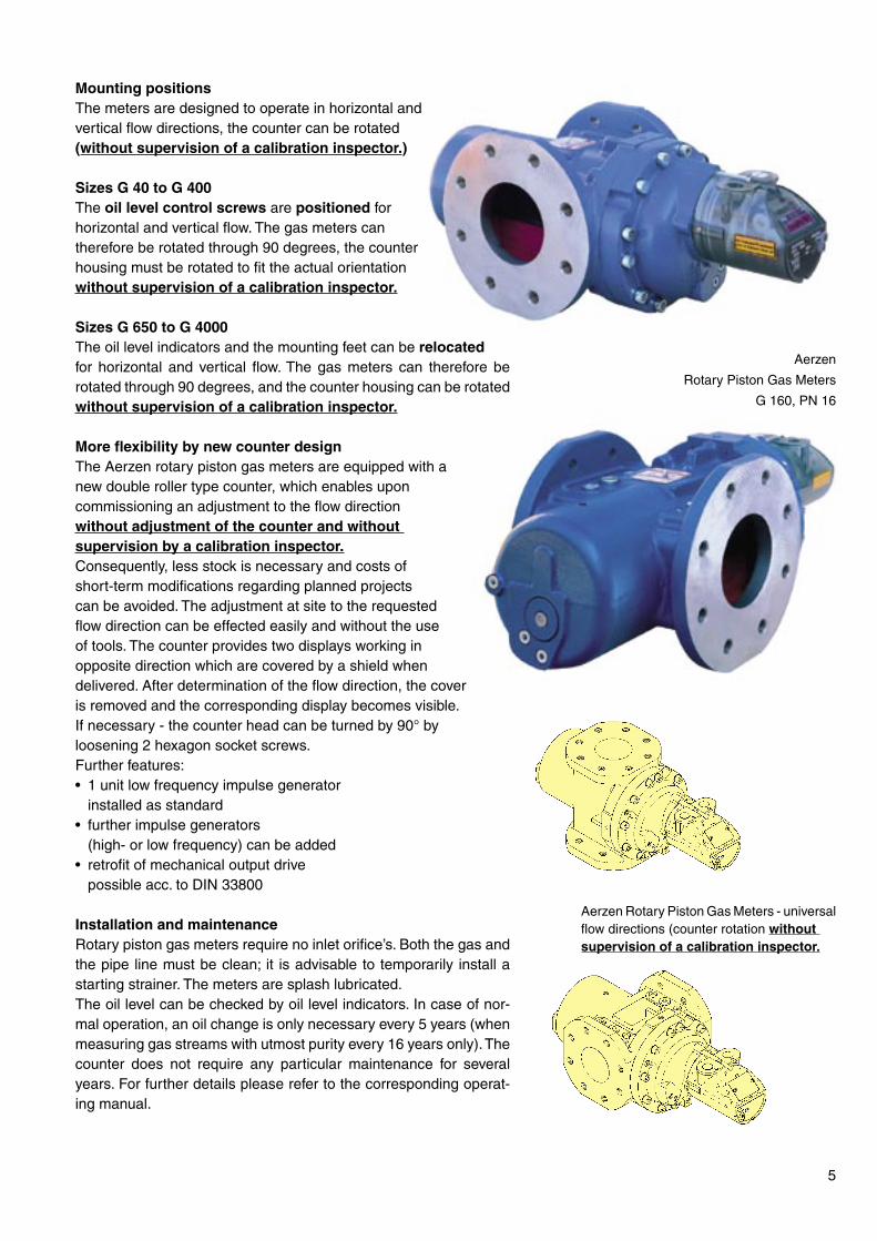
Mounting positionsThe meters are designed to operate in horizontal and vertical flow directions, the counter can be rotated (without supervision of a calibration inspector.)
Sizes G 40 to G 400The oil level control screws are positioned for horizontal and vertical flow. The gas meters can therefore be rotated through 90 degrees, the counter housing must be rotated to fit the actual orientation without supervision of a calibration inspector.
Sizes G 650 to G 4000The oil level indicators and the mounting feet can be relocated for horizontal and vertical flow. The gas meters can therefore be rotated through 90 degrees, and the counter housing can be rotated without supervision of a calibration inspector.
More flexibility by new counter designThe Aerzen rotary piston gas meters are equipped with a new double roller type counter, which enables upon commissioning an adjustment to the flow direction without adjustment of the counter and without supervision by a calibration inspector. Consequently, less stock is necessary and costs of short-term modifications regarding planned projects can be avoided. The adjustment at site to the requested flow direction can be effected easily and without the use of tools. The counter provides two displays working in opposite direction which are covered by a shield when delivered. After determination of the flow direction, the cover is removed and the corresponding display becomes visible. If necessary - the counter head can be turned by 90° by loosening 2 hexagon socket screws.Further features:• 1 unit low frequency impulse generator installed as standard• further impulse generators (high- or low frequency) can be added • retrofit of mechanical output drive possible acc. to DIN 33800
Installation and maintenanceRotary piston gas meters require no inlet orifice’s. Both the gas and the pipe line must be clean; it is advisable to temporarily install a starting strainer. The meters are splash lubricated. The oil level can be checked by oil level indicators. In case of nor-mal operation, an oil change is only necessary every 5 years (when measuring gas streams with utmost purity every 16 years only). The counter does not require any particular maintenance for several years. For further details please refer to the corresponding operat-ing manual.
Aerzen
Rotary Piston Gas Meters
G 160, PN 16
Aerzen Rotary Piston Gas Meters - universal flow directions (counter rotation without supervision of a calibration inspector.
5
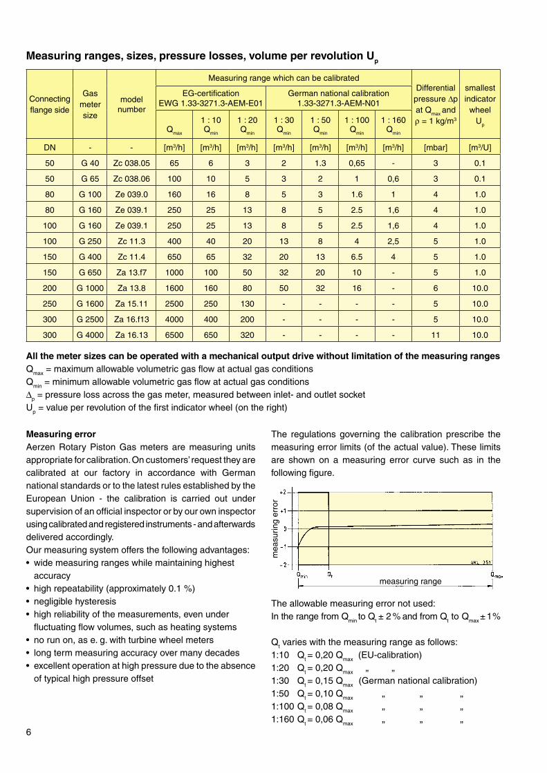
Measuring errorAerzen Rotary Piston Gas meters are measuring units appropriate for calibration. On customers’ request they are calibrated at our factory in accordance with German national standards or to the latest rules established by the European Union - the calibration is carried out under supervision of an official inspector or by our own inspector using calibrated and registered instruments - and afterwards delivered accordingly.Our measuring system offers the following advantages:• wide measuring ranges while maintaining highest accuracy • high repeatability (approximately 0.1 %) • negligible hysteresis • high reliability of the measurements, even under fluctuating flow volumes, such as heating systems• no run on, as e. g. with turbine wheel meters• long term measuring accuracy over many decades• excellent operation at high pressure due to the absence
of typical high pressure offset
The allowable measuring error not used:In the range from Qmin to Qt ± 2 % and from Qt to Qmax ± 1 %
Qt varies with the measuring range as follows:1:10 Qt = 0,20 Qmax (EU-calibration) 1:20 Qt = 0,20 Qmax „ „1:30 Qt = 0,15 Qmax (German national calibration)1:50 Qt = 0,10 Qmax „ „ „ 1:100 Qt = 0,08 Qmax „ „ „1:160 Qt = 0,06 Qmax „ „ „
Measuring ranges, sizes, pressure losses, volume per revolution Up
All the meter sizes can be operated with a mechanical output drive without limitation of the measuring rangesQmax = maximum allowable volumetric gas flow at actual gas conditionsQmin = minimum allowable volumetric gas flow at actual gas conditions ∆p = pressure loss across the gas meter, measured between inlet- and outlet socketUp = value per revolution of the first indicator wheel (on the right)
6
The regulations governing the calibration prescribe the measuring error limits (of the actual value). These limits are shown on a measuring error curve such as in the following figure.
Connecting flange side
Gas meter size
modelnumber
Measuring range which can be calibratedDifferential
pressure ∆p at Qmax and ρ = 1 kg/m3
smallest indicator
wheelUp
EG-certificationEWG 1.33-3271.3-AEM-E01
German national calibration1.33-3271.3-AEM-N01
Qmax
1 : 10Qmin
1 : 20Qmin
1 : 30Qmin
1 : 50Qmin
1 : 100Qmin
1 : 160Qmin
DN - - [m3/h] [m3/h] [m3/h] [m3/h] [m3/h] [m3/h] [m3/h] [mbar] [m3/U]
50 G 40 Zc 038.05 65 6 3 2 1.3 0,65 - 3 0.1
50 G 65 Zc 038.06 100 10 5 3 2 1 0,6 3 0.1
80 G 100 Ze 039.0 160 16 8 5 3 1.6 1 4 1.0
80 G 160 Ze 039.1 250 25 13 8 5 2.5 1,6 4 1.0
100 G 160 Ze 039.1 250 25 13 8 5 2.5 1,6 4 1.0
100 G 250 Zc 11.3 400 40 20 13 8 4 2,5 5 1.0
150 G 400 Zc 11.4 650 65 32 20 13 6.5 4 5 1.0
150 G 650 Za 13.f7 1000 100 50 32 20 10 - 5 1.0
200 G 1000 Za 13.8 1600 160 80 50 32 16 - 6 10.0
250 G 1600 Za 15.11 2500 250 130 - - - - 5 10.0
300 G 2500 Za 16.f13 4000 400 200 - - - - 5 10.0
300 G 4000 Za 16.13 6500 650 320 - - - - 11 10.0
measuring range
mea
surin
g er
ror
7
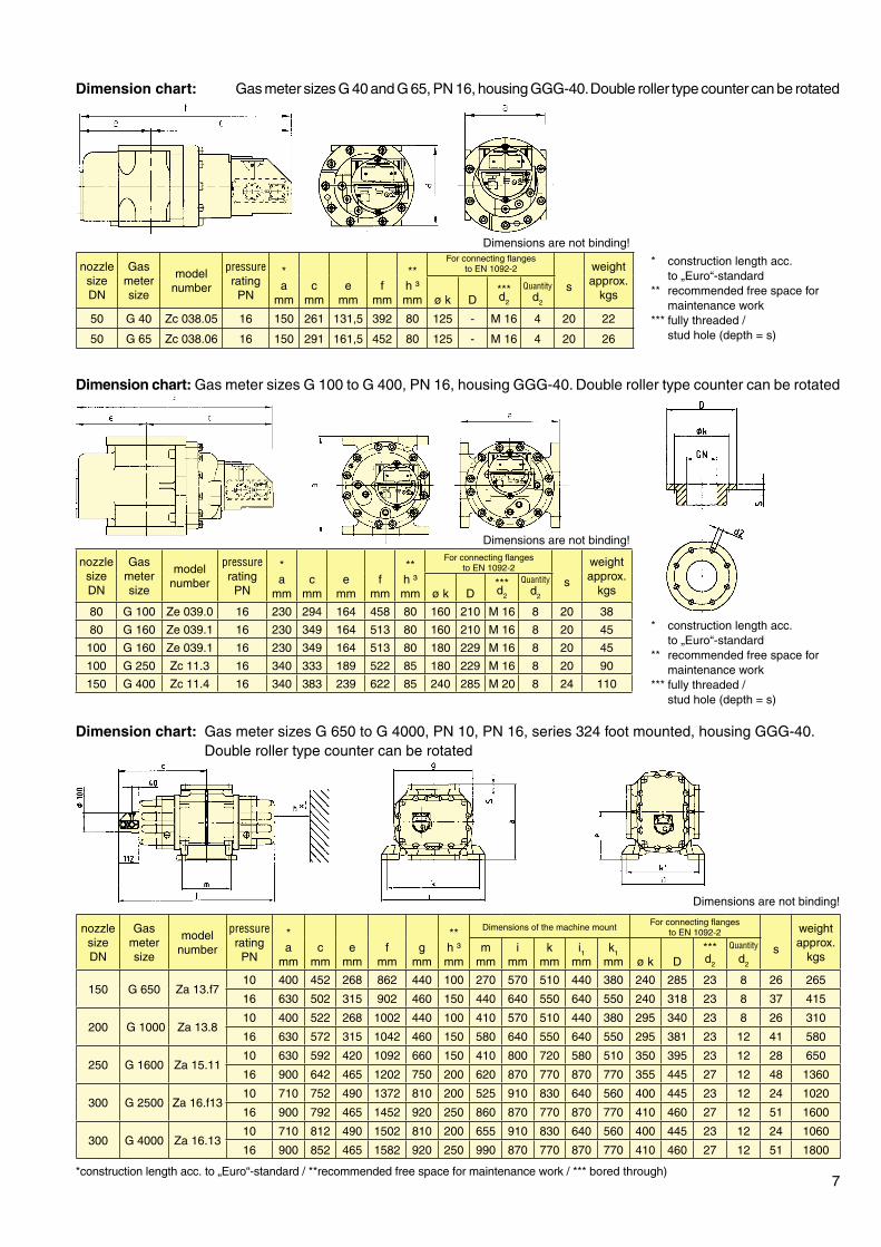
Dimension chart: Gas meter sizes G 40 and G 65, PN 16, housing GGG-40. Double roller type counter can be rotated
Dimension chart: Gas meter sizes G 650 to G 4000, PN 10, PN 16, series 324 foot mounted, housing GGG-40. Double roller type counter can be rotated
Dimensions are not binding!
*construction length acc. to „Euro“-standard / **recommended free space for maintenance work / *** bored through)
Dimension chart: Gas meter sizes G 100 to G 400, PN 16, housing GGG-40. Double roller type counter can be rotated
* construction length acc. to „Euro“-standard** recommended free space for maintenance work*** fully threaded / stud hole (depth = s)
* construction length acc. to „Euro“-standard** recommended free space for maintenance work*** fully threaded / stud hole (depth = s)
Dimensions are not binding!
Dimensions are not binding!
nozzle sizeDN
Gas meter size
model number
pressure rating PN
*a
mmc
mme
mmf
mm
**h ³mm
For connecting flanges to EN 1092-2
s
weight approx.
kgsø k D***d2
Quantity d2
50 G 40 Zc 038.05 16 150 261 131,5 392 80 125 - M 16 4 20 22
50 G 65 Zc 038.06 16 150 291 161,5 452 80 125 - M 16 4 20 26
nozzle sizeDN
Gas meter size
model number
pressure rating PN
*a
mmc
mme
mmf
mmg
mm
**h ³mm
Dimensions of the machine mountFor connecting flanges
to EN 1092-2
s
weight approx.
kgsm
mmi
mmk
mmi1
mmk1
mm ø k D***d2
Quantity d2
150 G 650 Za 13.f710 400 452 268 862 440 100 270 570 510 440 380 240 285 23 8 26 265
16 630 502 315 902 460 150 440 640 550 640 550 240 318 23 8 37 415
200 G 1000 Za 13.810 400 522 268 1002 440 100 410 570 510 440 380 295 340 23 8 26 310
16 630 572 315 1042 460 150 580 640 550 640 550 295 381 23 12 41 580
250 G 1600 Za 15.1110 630 592 420 1092 660 150 410 800 720 580 510 350 395 23 12 28 650
16 900 642 465 1202 750 200 620 870 770 870 770 355 445 27 12 48 1360
300 G 2500 Za 16.f1310 710 752 490 1372 810 200 525 910 830 640 560 400 445 23 12 24 1020
16 900 792 465 1452 920 250 860 870 770 870 770 410 460 27 12 51 1600
300 G 4000 Za 16.1310 710 812 490 1502 810 200 655 910 830 640 560 400 445 23 12 24 1060
16 900 852 465 1582 920 250 990 870 770 870 770 410 460 27 12 51 1800
nozzle sizeDN
Gas meter size
model number
pressure rating PN
*a
mmc
mme
mmf
mm
**h ³mm
For connecting flanges to EN 1092-2
s
weight approx.
kgsø k D***d2
Quantity d2
80 G 100 Ze 039.0 16 230 294 164 458 80 160 210 M 16 8 20 38
80 G 160 Ze 039.1 16 230 349 164 513 80 160 210 M 16 8 20 45
100 G 160 Ze 039.1 16 230 349 164 513 80 180 229 M 16 8 20 45
100 G 250 Zc 11.3 16 340 333 189 522 85 180 229 M 16 8 20 90
150 G 400 Zc 11.4 16 340 383 239 622 85 240 285 M 20 8 24 110
output drive location
8
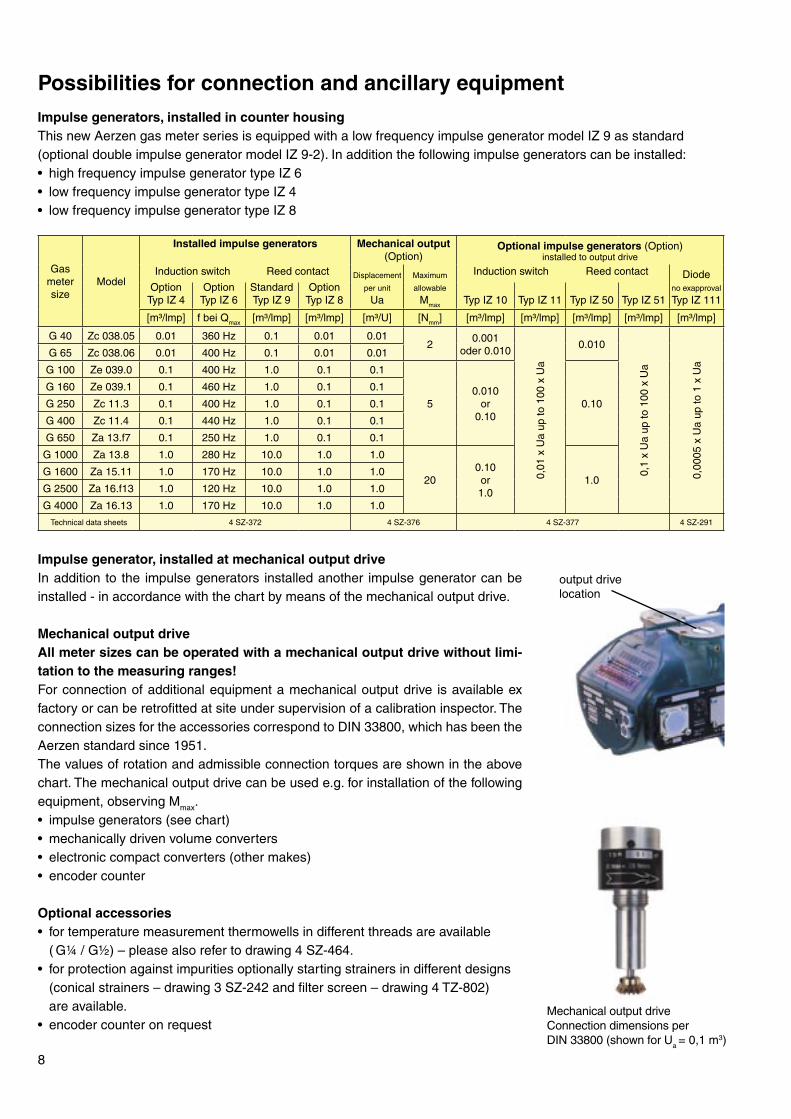
Impulse generators, installed in counter housingThis new Aerzen gas meter series is equipped with a low frequency impulse generator model IZ 9 as standard (optional double impulse generator model IZ 9-2). In addition the following impulse generators can be installed:• high frequency impulse generator type IZ 6• low frequency impulse generator type IZ 4• low frequency impulse generator type IZ 8
Possibilities for connection and ancillary equipment
Mechanical output driveConnection dimensions per DIN 33800 (shown for Ua = 0,1 m3)
Impulse generator, installed at mechanical output driveIn addition to the impulse generators installed another impulse generator can be installed - in accordance with the chart by means of the mechanical output drive.
Mechanical output driveAll meter sizes can be operated with a mechanical output drive without limi-tation to the measuring ranges!For connection of additional equipment a mechanical output drive is available ex factory or can be retrofitted at site under supervision of a calibration inspector. The connection sizes for the accessories correspond to DIN 33800, which has been the Aerzen standard since 1951.The values of rotation and admissible connection torques are shown in the above chart. The mechanical output drive can be used e.g. for installation of the following equipment, observing Mmax.• impulse generators (see chart)• mechanically driven volume converters• electronic compact converters (other makes)• encoder counter
Optional accessories• for temperature measurement thermowells in different threads are available ( G¼ / G½) – please also refer to drawing 4 SZ-464.• for protection against impurities optionally starting strainers in different designs (conical strainers – drawing 3 SZ-242 and filter screen – drawing 4 TZ-802) are available.• encoder counter on request
Gas meter size
Model
Installed impulse generators Mechanical output (Option)
Optional impulse generators (Option)installed to output drive
Induction switch Reed contact Displacement
per unit
Ua
Maximum
allowable
Mmax
Induction switch Reed contact Diodeno exapproval
Typ IZ 111Option
Typ IZ 4Option
Typ IZ 6StandardTyp IZ 9
OptionTyp IZ 8 Typ IZ 10 Typ IZ 11 Typ IZ 50 Typ IZ 51
[m³/lmp] f bei Qmax [m³/lmp] [m³/lmp] [m³/U] [Nmm] [m³/lmp] [m³/lmp] [m³/lmp] [m³/lmp] [m³/lmp]
G 40 Zc 038.05 0.01 360 Hz 0.1 0.01 0.012
0.001oder 0.010
0,01
x U
a up
to 1
00 x
Ua
0.010
0,1
x U
a up
to 1
00 x
Ua
0,00
05 x
Ua
up to
1 x
Ua
G 65 Zc 038.06 0.01 400 Hz 0.1 0.01 0.01
G 100 Ze 039.0 0.1 400 Hz 1.0 0.1 0.1
50.010
or0.10
0.10
G 160 Ze 039.1 0.1 460 Hz 1.0 0.1 0.1
G 250 Zc 11.3 0.1 400 Hz 1.0 0.1 0.1
G 400 Zc 11.4 0.1 440 Hz 1.0 0.1 0.1
G 650 Za 13.f7 0.1 250 Hz 1.0 0.1 0.1
G 1000 Za 13.8 1.0 280 Hz 10.0 1.0 1.0
200.10or1.0
1.0G 1600 Za 15.11 1.0 170 Hz 10.0 1.0 1.0
G 2500 Za 16.f13 1.0 120 Hz 10.0 1.0 1.0
G 4000 Za 16.13 1.0 170 Hz 10.0 1.0 1.0
Technical data sheets 4 SZ-372 4 SZ-376 4 SZ-377 4 SZ-291
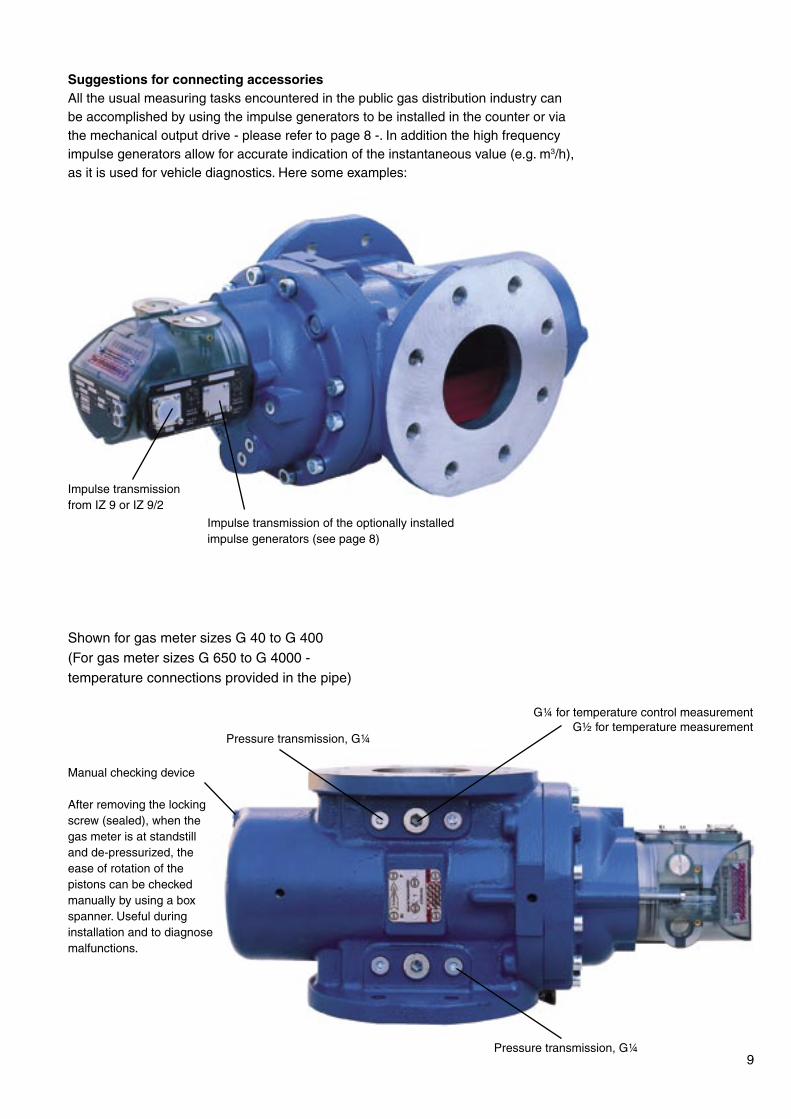
Suggestions for connecting accessoriesAll the usual measuring tasks encountered in the public gas distribution industry can be accomplished by using the impulse generators to be installed in the counter or via the mechanical output drive - please refer to page 8 -. In addition the high frequency impulse generators allow for accurate indication of the instantaneous value (e.g. m3/h), as it is used for vehicle diagnostics. Here some examples:
Manual checking device
After removing the locking screw (sealed), when the gas meter is at standstill and de-pressurized, the ease of rotation of the pistons can be checked manually by using a box spanner. Useful during installation and to diagnose malfunctions.
9
Impulse transmission of the optionally installed impulse generators (see page 8)
G¼ for temperature control measurementG½ for temperature measurement
Impulse transmissionfrom IZ 9 or IZ 9/2
Pressure transmission, G¼
Pressure transmission, G¼
Shown for gas meter sizes G 40 to G 400(For gas meter sizes G 650 to G 4000 - temperature connections provided in the pipe)
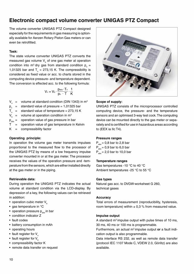
Scope of supply:UNIGAS PTZ consists of the microprocessor controlled computing device, the pressure- and the temperature sensors and an optimised 3-way test cock. The computing device can be mounted directly to the gas meter or sepa-rately and is certified for use in hazardous areas according to (EEX ia IIc T4).
Pressure rangesPabs = 0,8 bar to 2,8 bar Pabs = 0,9 bar to 6,0 bar Pabs = 2,0 bar to 10,0 bar
Temperature rangesGas temperatures -10 °C to 40 °CAmbient temperatures -25 °C to 55 °C
Gas typesNatural gas acc. to DVGW-worksheet G 260, technical gases
AccuracyTotal errors of measurement (reproducibility, hysteresis, room temperature) within ± 0,3 % from measured value.
Impulse outputA standard m3 impulse output with pulse times of 10 ms, 30 ms, 40 ms or 100 ms is programmable. Furthermore, an actual m3 impulse output or a fault indi-cation output is also programmable. Data interface RS 232, as well as remote data transfer (protocol IEC 1107 Mode C, VDEW 2.0, Görlitz) are also available.
The volume converter UNIGAS PTZ Compact designed especially for the requirements in gas measuring is option-ally available for Aerzen Rotary Piston Gas meters or can even be retrofitted.
Task:The state volume converter UNIGAS PTZ converts the measured gas volume Vb of one gas meter at operation condition into m3 dry gas from standard condition pn = 1,01325 bar and Tn = 273,15 K. The compressibility is considered as fixed value or acc. to charts stored in the computing device pressure- and temperature dependent. The conversion is effected acc. to the following formula:
Vn = volume at standard condition (DIN 1343) in m3
pn = standard value of pressure = 1,01325 barTn = standard value of temperature = 273,15 KVb = volume at operation condition in m3
pabs = operation value of gas pressure in barT = operation value of gas temperature in KelvinK = compressibility factor
Operating principle:In operation the volume gas meter transmits impulses proportional to the measured flow to the processor of the UNIGAS PTZ by means of a low frequency impulse converter mounted in or at the gas meter. The processor receives the values of the operation pressure and -tem-perature from the sensors, which are either installed directly at the gas meter or in the piping.
Retrievable data:During operation the UNIGAS PTZ indicates the actual volume at standard condition via the LCD-display. By depression of a key, the following values can be retrieved in addition:• operation cubic meter Vb
• gas temperature in °C• operation pressure pabs in bar• condition indicator Z• fault codes• battery consumption in mAh• operating hours• fault register for Vn
• fault register for Vb
• compressibility factor K• remote data transfer on request
10
Electronic compact volume converter UNIGAS PTZ Compact
11
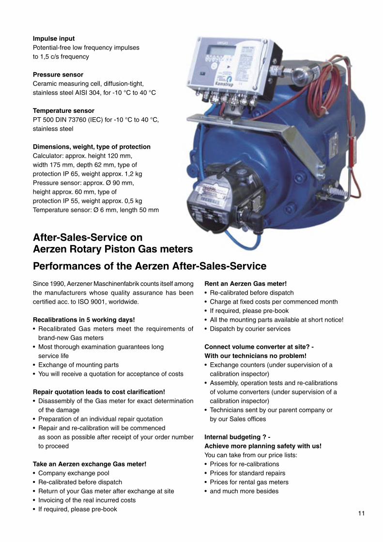
Impulse inputPotential-free low frequency impulses to 1,5 c/s frequency
Pressure sensorCeramic measuring cell, diffusion-tight, stainless steel AISI 304, for -10 °C to 40 °C
Temperature sensorPT 500 DIN 73760 (IEC) for -10 °C to 40 °C,stainless steel
Dimensions, weight, type of protectionCalculator: approx. height 120 mm, width 175 mm, depth 62 mm, type of protection IP 65, weight approx. 1,2 kgPressure sensor: approx. Ø 90 mm, height approx. 60 mm, type of protection IP 55, weight approx. 0,5 kg Temperature sensor: Ø 6 mm, length 50 mm
Since 1990, Aerzener Maschinenfabrik counts itself among the manufacturers whose quality assurance has been certified acc. to ISO 9001, worldwide.
Recalibrations in 5 working days!• Recalibrated Gas meters meet the requirements of
brand-new Gas meters• Most thorough examination guarantees long service life• Exchange of mounting parts• You will receive a quotation for acceptance of costs
Repair quotation leads to cost clarification!• Disassembly of the Gas meter for exact determination
of the damage• Preparation of an individual repair quotation• Repair and re-calibration will be commenced as soon as possible after receipt of your order number
to proceed
Take an Aerzen exchange Gas meter!• Company exchange pool• Re-calibrated before dispatch• Return of your Gas meter after exchange at site• Invoicing of the real incurred costs• If required, please pre-book
Rent an Aerzen Gas meter!• Re-calibrated before dispatch• Charge at fixed costs per commenced month• If required, please pre-book • All the mounting parts available at short notice!• Dispatch by courier services
Connect volume converter at site? -With our technicians no problem!• Exchange counters (under supervision of a calibration inspector)• Assembly, operation tests and re-calibrations of volume converters (under supervision of a calibration inspector)• Technicians sent by our parent company or by our Sales offices
Internal budgeting ? -Achieve more planning safety with us!You can take from our price lists:• Prices for re-calibrations• Prices for standard repairs• Prices for rental gas meters• and much more besides
After-Sales-Service on Aerzen Rotary Piston Gas meters
Performances of the Aerzen After-Sales-Service
A good address - everywhere
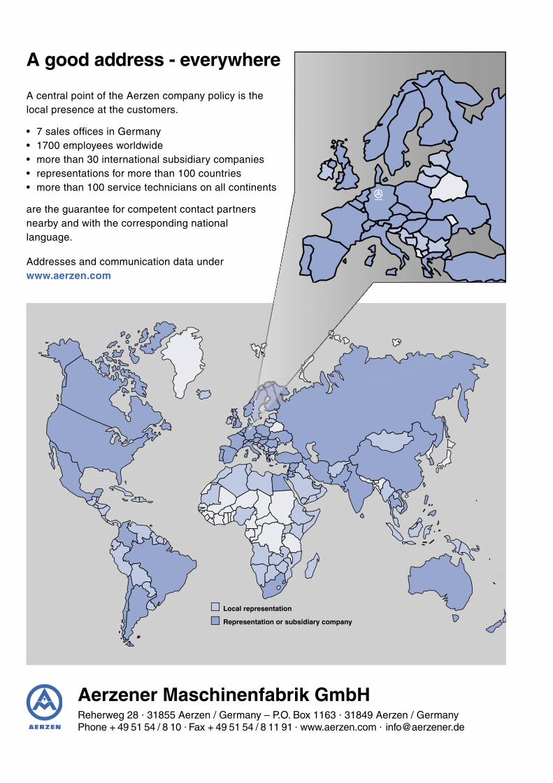
A central point of the Aerzen company policy is thelocal presence at the customers.
• 7 sales offi ces in Germany• 1700 employees worldwide• more than 30 international subsidiary companies• representations for more than 100 countries• more than 100 service technicians on all continents
are the guarantee for competent contact partnersnearby and with the corresponding nationallanguage.
Addresses and communication data underwww.aerzen.com
Aerzener Maschinenfabrik GmbHReherweg 28 . 31855 Aerzen / Germany – P.O. Box 1163 . 31849 Aerzen / Germany Phone + 49 51 54 / 8 10 . Fax + 49 51 54 / 8 11 91 . www.aerzen.com . [email protected]
Local representation
Representation or subsidiary company