Embed Size (px)
Citation preview
INDUS onboard 71-752
Betriebsanleitung (Original, Gültigkeit siehe letzte Seite)INDUS onboard 71-752 Sicherheitsschaltgerät Seite 3-11
Manuel d’utilisation (Validité voir la dernière page)INDUS onboard 71-752 Relais de sécurité
Operating Manual (see last page for validity)INDUS onboard 71-752 Safety Relay Page 13-21
Page 23-31En
glis
hFr
ança
isDe
utsc
h
Induktives Signalübertragungssystem / Inductive signal transmission system / Système de transmission de signal inductif
2
Übergabedokumentation / Documentation / Documentation de datation / Documentazione di consegna / DocumentatieAnlagenbeschreibung / Description / Description du système / Descrizione impianto / Beschrijving van de installatie
Anlagenart / Type of plant / Sorte du système / Tipo d’impianto / Type installatie
Hersteller / Manufacturer / Fabricant / Produttore / Fabrikant
Seriennummer / Serial number / Numéro de série / Numero di serie / Seriennummer
Datum der Inbetriebnahme / Commissioning date / Date de mise en marche / Data della messa in funzione / Datum van de ingebruikname
Aufstellort / Site of installation / Lieu de montage / Luogo d’installazione / Opstellingsplaats
Verwendete Steuerung / Control unit / Commande utilisée / Centralina di comando adottata / Gebruikte besturing
Zusatzkomponenten / Additional components / Composants supplémentaires / Componenti ausiliari / Bijkomende componenten
Funktionsprüfung / Functional test / Contrôle de fonction / Controllo funzionale / Functiecontrole
Sicherheitssensoren reagieren auf Betätigung / Safety sensor response to actuation / Le senseur de sécurité réagit à l’actionnement / Il sensore di sicurezza reagisce all’azionamento / Veiligheidssensor reageert op activering
Sicherheitssensoren reagieren auf Zuleitungsunterbrechung / Safety sensor response to supply line interruption / Le senseur de sécurité réagit à l’interruption de l’alimentation / Il sensore di sicurezza reagisce all’interruzione di collegamento Veiligheidssensor reageert op onderbreking van de toevoerleiding
ok
Name der ausführenden Firma / Owner / Nom de la société exécutrice / Nome della ditta esecutrice / Naam van de uitvoerende firma
Name des Installateurs / Installer / Nom de l’installateur / Nome dell’installatore / Naam van de installateur
Datum / Date / Date / Data / Datum Unterschrift / Signature / Signature / Firma / Handtekening
ok
2 3
INDUS onboard 71-752Induktives Signalübertragungssystem
Technische und betriebsrelevante Änderungen zu den in dieser Dokumentation aufgeführten Produkten und Geräten sind jederzeit auch ohne Vorankündigung vor-behalten.
1. Inhaltsverzeichnis
1. Inhaltsverzeichnis . . . . . . . . . . . . . . . . . . . . . . . . . . 3
2. Allgemeine Sicherheitsbestimmungen und Schutzmaßnahmen 4
3. Allgemeines und Funktionsbeschreibung . . . . . . . . . . . . . 5
4. Bestimmungsgemäße Verwendung . . . . . . . . . . . . . . . . 5
5. Systemkomponenten am Tor . . . . . . . . . . . . . . . . . . . . 6
6. Geräteübersicht . . . . . . . . . . . . . . . . . . . . . . . . . . . 6 6.1 Signalanzeigen. . . . . . . . . . . . . . . . . . . . . . . . . . . . . . . . . . . 6 6.2 Anschlussklemmen . . . . . . . . . . . . . . . . . . . . . . . . . . . . . . . . 7
7. Anschluss des Gerätes . . . . . . . . . . . . . . . . . . . . . . . 7 7.1 Voraussetzungen . . . . . . . . . . . . . . . . . . . . . . . . . . . . . . . . . 7 7.2 Versorgungsspannung . . . . . . . . . . . . . . . . . . . . . . . . . . . . . . 7 7.3 Anschluss feststehender Spulenkern . . . . . . . . . . . . . . . . . . . . . . 7 7.4 Anschluss feststehende Sicherheitskontaktleisten . . . . . . . . . . . . . . . 7 7.5 Anschluss Steuerstromkreise. . . . . . . . . . . . . . . . . . . . . . . . . . . 7
8. Anschließen der Sicherheitskontaktleisten . . . . . . . . . . . . 8 8.1 Anschluss am Spulenkern SPK 54 . . . . . . . . . . . . . . . . . . . . . . . . 8 8.2 Anschluss von mehreren Sicherheitskontaktleisten pro Signalgeberkreis . . . 8
9. Inbetriebnahme und Funktionsprüfung . . . . . . . . . . . . . . 8
10. Fehlerdiagnose . . . . . . . . . . . . . . . . . . . . . . . . . . . 9
11. Außerbetriebnahme und Entsorgung . . . . . . . . . . . . . . 10
12. Technische Daten . . . . . . . . . . . . . . . . . . . . . . . . . 10
13. EG Konformitätserklärung . . . . . . . . . . . . . . . . . . . . 11De
utsc
h

4
Das Schaltgerät ist nach EN ISO 13849-1 „Sicherheitsbezogene Teile von Steuerungen“ für Kat. 3 ausgelegt. Zur Einhaltung der Kat. 3 ist das Schaltgerät redundant, mit zwei sich gegenseitig abfragenden, zwangsgeführten Sicherheitsrelais pro Kanal aufgebaut.
Die Anforderungen der Tornormen EN 12978 „Schutzeinrichtungen für kraftbetätigte Türen und Tore“ und EN 12453 „Nutzungssicherheit kraftbetätigter Tore“ werden ebenfalls erfüllt.
Bei Nichtbeachtung oder vorsätzlichem Missbrauch entfällt die Haftung des Herstellers.
2. Allgemeine Sicherheitsbestimmungen und Schutzmaßnahmen • Hersteller und Benutzer der Anlage / Maschine, an der die Schutzeinrichtung verwendet wird, sind dafür verantwortlich, alle geltenden Sicherheitsvorschriften und -regeln in eigener Verantwortung abzustimmen und einzuhalten.• Die Schutzeinrichtung garantiert in Verbindung mit der übergeordneten Steuerung eine funktionale Sicherheit, nicht aber die Sicherheit der gesamten Anlage / Maschine. Vor dem Einsatz des Gerätes ist deshalb eine Sicherheitsbetrachtung der gesamten Anlage / Maschine nach der Maschinenrichtlinie 2006/42/EG oder nach entsprechender Produktnorm notwendig.• Die Betriebsanleitung muss ständig am Einsatzort der Schutzeinrichtung verfügbar sein. Sie ist von jeder Person, die mit der Bedienung, Wartung oder Instandhaltung der Schutzeinrichtung beauftragt wird, gründlich zu lesen und anzuwenden.• Die Installation und Inbetriebnahme der Schutzeinrichtung darf nur durch Fachpersonal erfolgen, die mit dieser Betriebsanleitung und den geltenden Vorschriften über Arbeitssicherheit und Unfallver- hütung vertraut sind. Die Hinweise in dieser Anleitung sind unbedingt zu beachten und einzuhalten. Elektrische Arbeiten dürfen nur von Elektrofachkräften durchgeführt werden.• Sicherheitsvorschriften der Elektrotechnik und der Berufsgenossenschaft sind zu beachten.• Bei Arbeiten am Schaltgerät ist dieses spannungsfrei zu schalten, auf Spannungsfreiheit zu prüfen und gegen Wiedereinschalten zu sichern.• Werden die potentialfreien Kontakte der Relaisausgänge mit einer gefährlichen Spannung fremdge- speist, ist sicherzustellen, dass diese bei Arbeiten an dem Schaltgerät ebenfalls abgeschaltet werden.• Das Schaltgerät enthält keine vom Anwender zu wartende Bauteile. Durch eigenmächtige Umbauten bzw. Reparaturen am Schaltgerät erlischt jegliche Gewährleistung und Haftung des Herstellers.• Das Schutzsystem ist in geeigneten Zeitabständen von Sachkundigen zu prüfen und in jederzeit nach- vollziehbarer Weise zu dokumentieren.
Sicherheitshinweise • Das Schaltgerät ermöglicht den Betrieb an 24 V DC. Der Anschluss der Betriebsspannung an die falschen Klemmen kann das Schaltgerät zerstören.• Das Schaltgerät ist in einem Schaltschrank zu montieren.• Nicht in unmittelbarer Nähe von starken Wärmequellen montieren.• Bei kapazitiven und induktiven Verbrauchern ist für eine ausreichende Schutzbeschaltung zu sorgen.
Deut
sch
Induktives Signalübertragungssystem
4 5
INDUS onboard 71-752Induktives Signalübertragungssystem
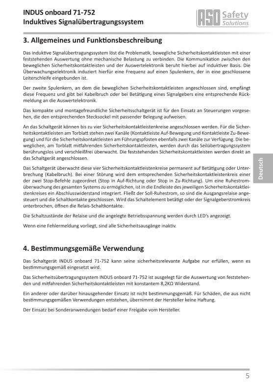
3. Allgemeines und FunktionsbeschreibungDas induktive Signalübertragungssystem löst die Problematik, bewegliche Sicherheitskontaktleisten mit einer feststehenden Auswertung ohne mechanische Belastung zu verbinden. Die Kommunikation zwischen den beweglichen Sicherheitskontaktleisten und der Auswertelektronik beruht hierbei auf induktiver Basis. Die Überwachungselektronik induziert hierfür eine Frequenz auf einen Spulenkern, der in eine geschlossene Leiterschleife eingebunden ist.
Der zweite Spulenkern, an dem die beweglichen Sicherheitskontaktleisten angeschlossen sind, empfängt diese Frequenz und gibt bei Kabelbruch oder bei Betätigung eines Signalgebers eine entsprechende Rück-meldung an die Auswertelektronik.
Das kompakte und montagefreundliche Sicherheitsschaltgerät ist für den Einsatz an Steuerungen vorgese-hen, die den entsprechenden Stecksockel mit passender Belegung aufweisen.
An das Schaltgerät können bis zu vier Sicherheitskontaktleistenkreise angeschlossen werden. Für die Sicher-heitskontaktleisten am Torblatt stehen zwei Kanäle (Kontaktleiste Auf-Bewegung und Kontaktleiste Zu-Bewe-gung) und für die Sicherheitskontaktleisten am Führungspfosten ebenfalls zwei Kanäle zur Verfügung. Die be-weglichen, am Torblatt mitfahrenden Sicherheitskontaktleisten, werden durch das Seilübertragungssystem berührungslos und verschleißfrei überwacht. Die feststehenden Sicherheitskontaktleisten werden direkt an das Schaltgerät angeschlossen.
Das Schaltgerät überwacht diese vier Sicherheitskontaktleistenkreise permanent auf Betätigung oder Unter- brechung (Kabelbruch). Bei einer Störung wird dem entsprechenden Sicherheitskontaktleistenkreis einer der zwei Stop-Befehle zugeordnet (Stop in Auf-Richtung oder Stop in Zu-Richtung). Um eine Ruhestrom- überwachung des gesamten Systems zu ermöglichen, ist in die Endleiste des jeweiligen Sicherheitskontaktlei-stenkreises ein Abschlusswiderstand integriert. Fließt der Soll-Ruhestrom, so sind die Ausgangsrelaise ange-steuert und die Schaltkontakte geschlossen. Wird das Schaltelement betätigt oder der Signalgeberstromkreis unterbrochen, öffnen die Relais-Schaltkontakte.
Die Schaltzustände der Relaise und die angelegte Betriebsspannung werden durch LED‘s angezeigt.
Wenn eine Fehlermeldung vorliegt, sind alle Sicherheitsausgänge inaktiv.
4. Bestimmungsgemäße VerwendungDas Schaltgerät INDUS onboard 71-752 kann seine sicherheitsrelevante Aufgabe nur erfüllen, wenn es bestimmungsgemäß eingesetzt wird.
Das Sicherheitsübertragungssystem INDUS onboard 71-752 ist ausgelegt für die Auswertung von feststehen-den und mitfahrenden Sicherheitskontaktleisten mit konstantem 8,2KΩ Widerstand.
Ein anderer oder darüber hinausgehender Einsatz ist nicht bestimmungsgemäß. Für Schäden, die aus nicht bestimmungsgemäßen Verwendungen entstehen, übernimmt der Hersteller keine Haftung.
Der Einsatz bei Sonderanwendungen bedarf einer Freigabe vom Hersteller.
Deut
sch
6
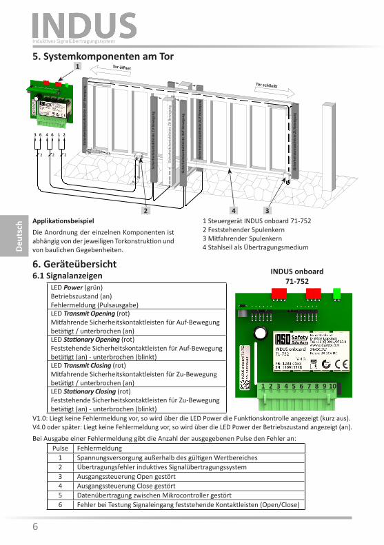
5. Systemkomponenten am Tor
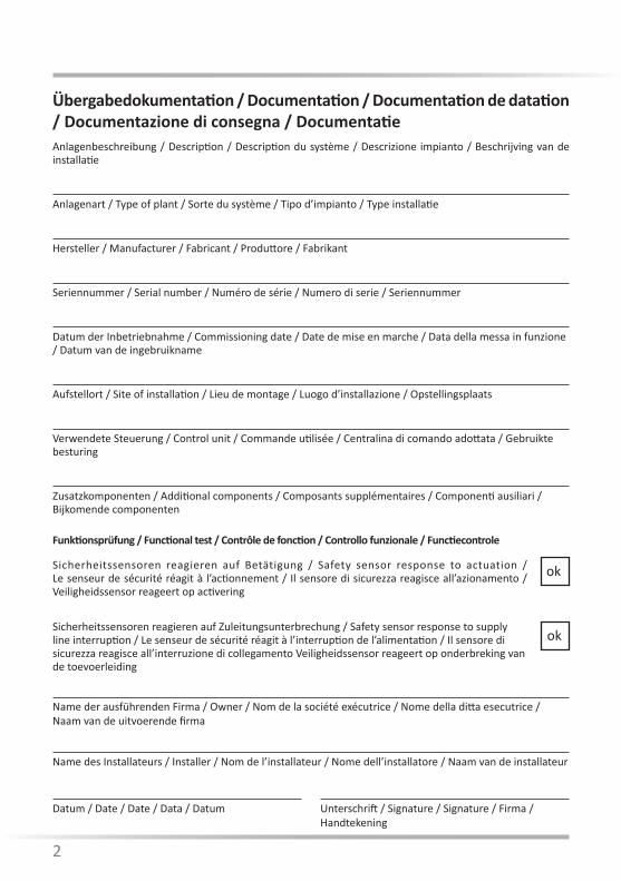
1 Steuergerät INDUS onboard 71-7522 Feststehender Spulenkern3 Mitfahrender Spulenkern4 Stahlseil als Übertragungsmedium
ApplikationsbeispielDie Anordnung der einzelnen Komponenten ist abhängig von der jeweiligen Torkonstruktion und von baulichen Gegebenheiten.
ISK 71-24
Transmit OpeningStationary Opening
TransmitStationary
Power
ISK 71-242
33 11 10 1 2
2 2 2
2 4 3
Tor öffnet
Tor schließt
Sich
erhe
itsko
ntak
tleist
e AU
F Be
weg
ung
Sich
erhe
itsko
ntak
tleist
e AU
F Be
weg
ung
Sich
erhe
itsko
ntak
tleist
e AU
F Be
weg
ung
Sich
erhe
itsko
ntak
tleist
e ZU
Bew
egun
g
Sich
erhe
itsko
ntak
tleist
e ZU
Bew
egun
g
Sich
erhe
itsko
ntak
tleist
e ZU
Bew
egun
g
Deut
sch
Induktives Signalübertragungssystem
INDUS onboard 71-752
1
3 216 4 6
6. Geräteübersicht6.1 Signalanzeigen
LED Power (grün)Betriebszustand (an)Fehlermeldung (Pulsausgabe)LED Transmit Opening (rot)Mitfahrende Sicherheitskontaktleisten für Auf-Bewegungbetätigt / unterbrochen (an)LED Stationary Opening (rot)Feststehende Sicherheitskontaktleisten für Auf-Bewegungbetätigt (an) - unterbrochen (blinkt)LED Transmit Closing (rot)Mitfahrende Sicherheitskontaktleisten für Zu-Bewegungbetätigt / unterbrochen (an)LED Stationary Closing (rot)Feststehende Sicherheitskontaktleisten für Zu-Bewegungbetätigt (an) - unterbrochen (blinkt)
Pulse Fehlermeldung1 Spannungsversorgung außerhalb des gültigen Wertbereiches2 Übertragungsfehler induktives Signalübertragungssystem3 Ausgangssteuerung Open gestört4 Ausgangssteuerung Close gestört5 Datenübertragung zwischen Mikrocontroller gestört6 Fehler bei Testung Signaleingang feststehende Kontaktleisten (Open/Close)
V1.0: Liegt keine Fehlermeldung vor, so wird über die LED Power die Funktionskontrolle angezeigt (kurz aus).V4.0 oder später: Liegt keine Fehlermeldung vor, so wird über die LED Power der Betriebszustand angezeigt (an).Bei Ausgabe einer Fehlermeldung gibt die Anzahl der ausgegebenen Pulse den Fehler an:
109871 2 3 4 5 6
6 7
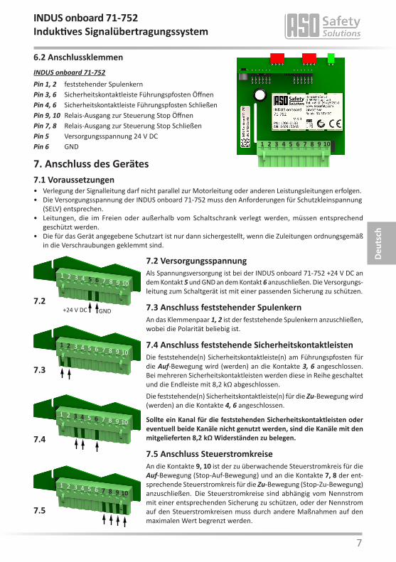
7. Anschluss des Gerätes7.1 Voraussetzungen• Verlegung der Signalleitung darf nicht parallel zur Motorleitung oder anderen Leistungsleitungen erfolgen.• Die Versorgungsspannung der INDUS onboard 71-752 muss den Anforderungen für Schutzkleinspannung (SELV) entsprechen.• Leitungen, die im Freien oder außerhalb vom Schaltschrank verlegt werden, müssen entsprechend geschützt werden.• Die für das Gerät angegebene Schutzart ist nur dann sichergestellt, wenn die Zuleitungen ordnungsgemäß in die Verschraubungen geklemmt sind.
INDUS onboard 71-752 Pin 1, 2 feststehender SpulenkernPin 3, 6 Sicherheitskontaktleiste Führungspfosten ÖffnenPin 4, 6 Sicherheitskontaktleiste Führungspfosten Schließen Pin 9, 10 Relais-Ausgang zur Steuerung Stop ÖffnenPin 7, 8 Relais-Ausgang zur Steuerung Stop SchließenPin 5 Versorgungsspannung 24 V DCPin 6 GND
7.2 VersorgungsspannungAls Spannungsversorgung ist bei der INDUS onboard 71-752 +24 V DC an dem Kontakt 5 und GND an dem Kontakt 6 anzuschließen. Die Versorgungs-leitung zum Schaltgerät ist mit einer passenden Sicherung zu schützen.
7.3 Anschluss feststehender SpulenkernAn das Klemmenpaar 1, 2 ist der feststehende Spulenkern anzuschließen, wobei die Polarität beliebig ist.
7.4 Anschluss feststehende SicherheitskontaktleistenDie feststehende(n) Sicherheitskontaktleiste(n) am Führungspfosten für die Auf-Bewegung wird (werden) an die Kontakte 3, 6 angeschlossen. Bei mehreren Sicherheitskontaktleisten werden diese in Reihe geschaltet und die Endleiste mit 8,2 kΩ abgeschlossen. Die feststehende(n) Sicherheitskontaktleiste(n) für die Zu-Bewegung wird (werden) an die Kontakte 4, 6 angeschlossen.
Sollte ein Kanal für die feststehenden Sicherheitskontaktleisten oder eventuell beide Kanäle nicht genutzt werden, sind die Kanäle mit den mitgelieferten 8,2 kΩ Widerständen zu belegen.
7.5 Anschluss SteuerstromkreiseAn die Kontakte 9, 10 ist der zu überwachende Steuerstromkreis für die Auf-Bewegung (Stop-Auf-Bewegung) und an die Kontakte 7, 8 der ent-sprechende Steuerstromkreis für die Zu-Bewegung (Stop-Zu-Bewegung) anzuschließen. Die Steuerstromkreise sind abhängig vom Nennstrom mit einer entsprechenden Sicherung zu schützen, oder der Nennstrom auf den Steuerstromkreisen muss durch andere Maßnahmen auf den maximalen Wert begrenzt werden.
6.2 Anschlussklemmen
Deut
sch
INDUS onboard 71-752Induktives Signalübertragungssystem
109871 2 3 4 5 6
109871 2 3 4 5 6
+24 V DC GND7.2
109871 2 3 4 5 6
7.3
109871 2 3 4 5 6
7.4
109871 2 3 4 5 6
7.5
8
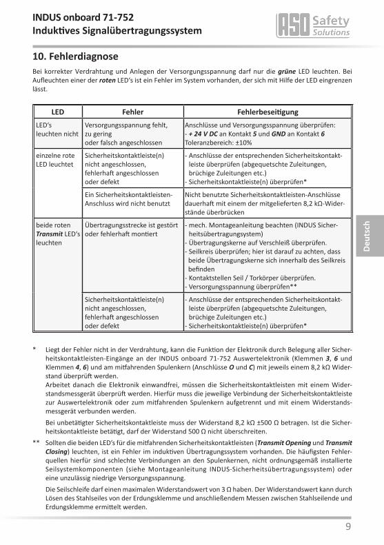
ASO-Sicherheitskontaktleisten dürfen nicht parallel geschaltet werden.
9. Inbetriebnahme / FunktionsprüfungNach entsprechendem Anschluss aller elektrischen Verbindungen und Einschalten der Versorgungsspannung, muss die Toranlage auf korrekte Funktion überprüft werden. Hierzu sind alle Sicherheitskontaktleisten der Reihe nach zu betätigen und die entsprechenden Reaktionen des Schaltgerätes zu kontrollieren.
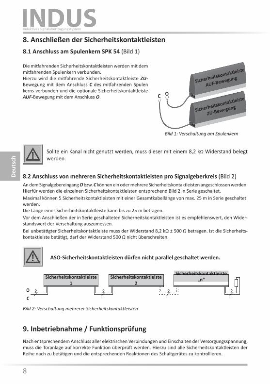
8. Anschließen der Sicherheitskontaktleisten8.1 Anschluss am Spulenkern SPK 54 (Bild 1)
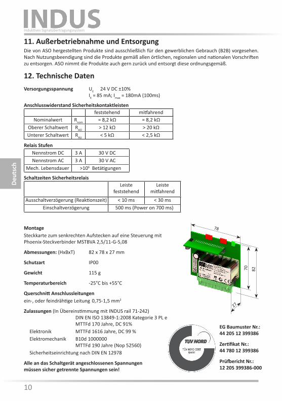
8.2 Anschluss von mehreren Sicherheitskontaktleisten pro Signalgeberkreis (Bild 2)An dem Signalgebereingang O bzw. C können ein oder mehrere Sicherheitskontaktleisten angeschlossen werden. Hierfür werden die einzelnen Sicherheitskontaktleisten entsprechend Bild 2 in Serie geschaltet. Maximal können 5 Sicherheitskontaktleisten mit einer Gesamtkabellänge von max. 25 m in Serie geschaltet werden. Die Länge einer Sicherheitskontaktleiste kann bis zu 25 m betragen. Vor dem Anschließen der in Serie geschalteten Sicherheitskontaktleisten ist es empfehlenswert, den Wider-standswert der Verschaltung auszumessen.Bei unbetätigter Sicherheitskontaktleiste muss der Widerstand 8,2 kΩ ± 500 Ω betragen. Ist die Sicherheits-kontaktleiste betätigt, darf der Widerstand 500 Ω nicht überschreiten.
Sollte ein Kanal nicht genutzt werden, muss dieser mit einem 8,2 kΩ Widerstand belegt werden.
Die mitfahrenden Sicherheitskontaktleisten werden mit dem mitfahrenden Spulenkern verbunden.Hierzu wird die mitfahrende Sicherheitskontaktleiste ZU- Bewegung mit dem Anschluss C des mitfahrenden Spulen kerns verbunden und die optionale Sicherheitskontaktleiste AUF-Bewegung mit dem Anschluss O.
Sicherheitskontaktleiste 1
Sicherheitskontaktleiste 2
Sicherheitskontaktleiste „n“
O
C
Bild 2: Verschaltung mehrerer Sicherheitskontaktleisten
Deut
sch
Induktives Signalübertragungssystem
Sicherheitskontaktleiste
ZU-Bewegung
Sicherheitskontaktleiste
AUF-Bewegung
OC
Bild 1: Verschaltung am Spulenkern
2222
8 9
10. FehlerdiagnoseBei korrekter Verdrahtung und Anlegen der Versorgungsspannung darf nur die grüne LED leuchten. Bei Aufleuchten einer der roten LED‘s ist ein Fehler im System vorhanden, der sich mit Hilfe der LED eingrenzen lässt.
LED Fehler FehlerbeseitigungLED‘s leuchten nicht
Versorgungsspannung fehlt,zu geringoder falsch angeschlossen
Anschlüsse und Versorgungsspannung überprüfen:- + 24 V DC an Kontakt 5 und GND an Kontakt 6Toleranzbereich: ±10%
einzelne rote LED leuchtet
Sicherheitskontaktleiste(n)nicht angeschlossen,fehlerhaft angeschlossenoder defekt
- Anschlüsse der entsprechenden Sicherheitskontakt-leiste überprüfen (abgequetschte Zuleitungen, brüchige Zuleitungen etc.)
- Sicherheitskontaktleiste(n) überprüfen*
Ein Sicherheitskontaktleisten-Anschluss wird nicht benutzt
Nicht benutzte Sicherheitskontaktleisten-Anschlüsse dauerhaft mit einem der mitgelieferten 8,2 kΩ-Wider-stände überbrücken
beide roten Transmit LED‘s leuchten
Übertragungsstrecke ist gestörtoder fehlerhaft montiert
- mech. Montageanleitung beachten (INDUS Sicher-heitsübertragungsystem)
- Übertragungskerne auf Verschleiß überprüfen. - Seilkreis überprüfen; hier ist darauf zu achten, dass beide Übertragungskerne sich innerhalb des Seilkreis befinden- Kontaktstellen Seil / Torkörper überprüfen.- Versorgungsspannung überprüfen**
Sicherheitskontaktleiste(n)nicht angeschlossen,fehlerhaft angeschlossenoder defekt
- Anschlüsse der entsprechenden Sicherheitskontakt- leiste überprüfen (abgequetschte Zuleitungen, brüchige Zuleitungen etc.)
- Sicherheitskontaktleiste(n) überprüfen*
* Liegt der Fehler nicht in der Verdrahtung, kann die Funktion der Elektronik durch Belegung aller Sicher- heitskontaktleisten-Eingänge an der INDUS onboard 71-752 Auswertelektronik (Klemmen 3, 6 und Klemmen 4, 6) und am mitfahrenden Spulenkern (Anschlüsse O und C) mit jeweils einem 8,2 kΩ Wider- stand überprüft werden.
Arbeitet danach die Elektronik einwandfrei, müssen die Sicherheitskontaktleisten mit einem Wider- standsmessgerät überprüft werden. Hierfür muss die jeweilige Verbindung der Sicherheitskontaktleiste zur Auswertelektronik oder zum mitfahrenden Spulenkern aufgetrennt und mit einem Widerstands- messgerät verbunden werden.
Bei unbetätigter Sicherheitskontaktleiste muss der Widerstand 8,2 kΩ ±500 Ω betragen. Ist die Sicher-heitskontaktleiste betätigt, darf der Widerstand 500 Ω nicht überschreiten.
** Sollten die beiden LED’s für die mitfahrenden Sicherheitskontaktleisten (Transmit Opening und Transmit Closing) leuchten, ist ein Fehler im induktiven Übertragungssystem vorhanden. Die häufigsten Fehler- quellen hierfür sind schlechte Verbindungen an den Spulenkernen, nicht ordnungsgemäß installierte Seilsystemkomponenten (siehe Montageanleitung INDUS-Sicherheitsübertragungssystem) oder eine unzulässig niedrige Versorgungsspannung.
Die Seilschleife darf einen maximalen Widerstandswert von 3 Ω haben. Der Widerstandswert kann durch Lösen des Stahlseiles von der Erdungsklemme und anschließendem Messen zwischen Stahlseilende und Erdungsklemme ermittelt werden.
Deut
sch
INDUS onboard 71-752Induktives Signalübertragungssystem
10
11. Außerbetriebnahme und EntsorgungDie von ASO hergestellten Produkte sind ausschließlich für den gewerblichen Gebrauch (B2B) vorgesehen. Nach Nutzungsbeendigung sind die Produkte gemäß allen örtlichen, regionalen und nationalen Vorschriften zu entsorgen. ASO nimmt die Produkte auch gern zurück und entsorgt diese ordnungsgemäß.
12. Technische DatenVersorgungsspannung UE 24 V DC ±10% IE = 85 mA; Imax = 180mA (100ms)
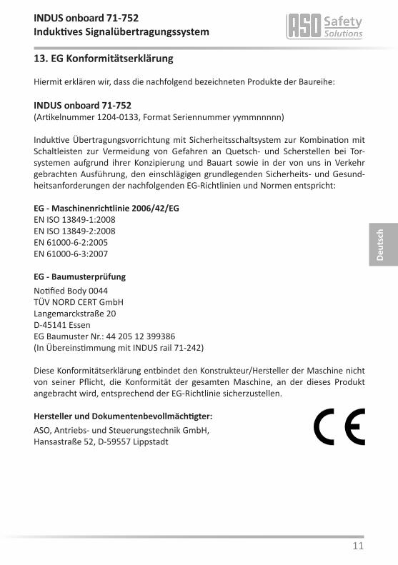
MontageSteckkarte zum senkrechten Aufstecken auf eine Steuerung mit Phoenix-Steckverbinder MSTBVA 2,5/11-G-5,08
Abmessungen: (HxBxT) 82 x 78 x 27 mm
Schutzart IP00
Gewicht 115 g
Temperaturbereich -25°C bis +55°C
Querschnitt Anschlussleitungenein-, oder feindrähtige Leitung 0,75-1,5 mm2
Zulassungen (In Übereinstimmung mit INDUS rail 71-242) DIN EN ISO 13849-1:2008 Kategorie 3 PL e MTTFd 170 Jahre, DC 91% Elektronik MTTFd 1616 Jahre, DC 99 % Elektromechanik B10d 1000000 MTTFd 190 Jahre (Nop 52560) Sicherheitseinrichtung nach DIN EN 12978
Alle an das Schaltgerät angeschlossenen Spannungen müssen sicher getrennte Spannungen sein!
Prüfbericht Nr.:12 205 399386-000
Zertifikat Nr.:44 780 12 399386
EG Baumuster Nr.: 44 205 12 399386
feststehend mitfahrendNominalwert Rnom = 8,2 kΩ = 8,2 kΩ
Oberer Schaltwert RAO > 12 kΩ > 20 kΩUnterer Schaltwert RAU < 5 kΩ < 2,5 kΩ
Anschlusswiderstand Sicherheitskontaktleisten
Nennstrom DC 3 A 30 V DCNennstrom AC 3 A 30 V AC
Mech. Lebensdauer >106 Betätigungen
Relais Stufen
Leistefeststehend
Leistemitfahrend
Ausschaltverzögerung (Reaktionszeit) < 10 ms < 30 msEinschaltverzögerung 500 ms (Power on 700 ms)
Schaltzeiten Sicherheitsrelais
Deut
sch
Induktives Signalübertragungssystem
78
27
70 82
10 11
13. EG Konformitätserklärung
Hiermit erklären wir, dass die nachfolgend bezeichneten Produkte der Baureihe:
INDUS onboard 71-752(Artikelnummer 1204-0133, Format Seriennummer yymmnnnnn)
Induktive Übertragungsvorrichtung mit Sicherheitsschaltsystem zur Kombination mit Schaltleisten zur Vermeidung von Gefahren an Quetsch- und Scherstellen bei Tor- systemen aufgrund ihrer Konzipierung und Bauart sowie in der von uns in Verkehr gebrachten Ausführung, den einschlägigen grundlegenden Sicherheits- und Gesund-heitsanforderungen der nachfolgenden EG-Richtlinien und Normen entspricht:
EG - Maschinenrichtlinie 2006/42/EGEN ISO 13849-1:2008EN ISO 13849-2:2008EN 61000-6-2:2005EN 61000-6-3:2007
EG - BaumusterprüfungNotified Body 0044TÜV NORD CERT GmbHLangemarckstraße 20D-45141 EssenEG Baumuster Nr.: 44 205 12 399386(In Übereinstimmung mit INDUS rail 71-242)
Diese Konformitätserklärung entbindet den Konstrukteur/Hersteller der Maschine nicht von seiner Pflicht, die Konformität der gesamten Maschine, an der dieses Produkt angebracht wird, entsprechend der EG-Richtlinie sicherzustellen.
Hersteller und Dokumentenbevollmächtigter:ASO, Antriebs- und Steuerungstechnik GmbH,Hansastraße 52, D-59557 Lippstadt
Deut
sch
INDUS onboard 71-752Induktives Signalübertragungssystem

12

12 13
INDUS onboard 71-752Inductive signal transmission system
We reserve the right to make technical and operationally relevant changes to the products and devices described in this documentation at any time and without prior notice.
Engl
ish
1. Contents
1. Contents . . . . . . . . . . . . . . . . . . . . . . . . . . . . . . 13
2. General safety regulations and protective measures . . . . . 14
3. General and Function . . . . . . . . . . . . . . . . . . . . . . . 15
4. Proper use . . . . . . . . . . . . . . . . . . . . . . . . . . . . . 15
5. System components fitted to the gate. . . . . . . . . . . . . . 16
6. Device overview . . . . . . . . . . . . . . . . . . . . . . . . . . 16 6.1 Signal Indicators . . . . . . . . . . . . . . . . . . . . . . . . . . . . . . . . . 16 6.2 Connection terminals . . . . . . . . . . . . . . . . . . . . . . . . . . . . . . 17
7. Connecting the device . . . . . . . . . . . . . . . . . . . . . . 17 7.1 Prerequisites. . . . . . . . . . . . . . . . . . . . . . . . . . . . . . . . . . . 17 7.2 Supply voltage . . . . . . . . . . . . . . . . . . . . . . . . . . . . . . . . . . 17 7.3 Connecting the stationary coil core . . . . . . . . . . . . . . . . . . . . . . 17 7.4 Connecting the stationary safety contact edges . . . . . . . . . . . . . . . 17 7.5 Connecting the control circuits. . . . . . . . . . . . . . . . . . . . . . . . . 17
8. Connecting the safety contact edges . . . . . . . . . . . . . . 18 8.1 Connecting to the coil core SPK 54 . . . . . . . . . . . . . . . . . . . . . . 18 8.2 Connecting multiple safety contact edges per sensor circuit . . . . . . . . 18
9. Commissioning and functional test . . . . . . . . . . . . . . . . 18
10. Error diagnosis. . . . . . . . . . . . . . . . . . . . . . . . . . . 19
11. Taking out of service and disposal . . . . . . . . . . . . . . . . 20
12. Technical specifications . . . . . . . . . . . . . . . . . . . . . . 20
13. EC declaration of conformity . . . . . . . . . . . . . . . . . . . 21

14
The switching unit complies with EN ISO 13849-1 "Safety-related parts of control systems", Cat. 3. To meet Cat. 3 requirements, the switching unit has a redundant structure with two, two-way polling, forcibly actuated safety relays per channel.
The requirements of EN 12978 "Safety devices for power operated doors and gates" and EN 12453 "Safety in use of power operated gates" are also fulfilled.
The manufacturer assumes no liability in the event of non-observance or intentional abuse.
2. General safety regulations and protective measures • The manufacturer and users of the plant / machine on which the protection is being used are responsible
for implementing and following all applicable safety regulations and rules.• When used in conjunction with the higher-order controller, the protection guarantees functional safety,
but not the safety of the entire plant / machine. The safety of the entire plant / machine must, therefore, be assessed in accordance with machinery directive 2006/42/EG or appropriate product norm before using the device.
• The operating manual must always be available at the place of installation of the protection. They must be read thoroughly and observed by all persons involved in the operation, maintenance and
servicing of the protection.• The protection must only be installed and commissioned by professionals familiar with these opera-
ting instructions and the applicable operational safety and accident prevention regulations. All of the instructions provided in these operating instructions must be observed and followed.
All electrical work must only be performed by skilled electricians.• All relevant electrical engineering and Employer's Liability Insurance Association safety regulations must
be observed.• During work on the switching unit, it is to be switched to zero potential, checked to ensure that it is at
zero potential and protected against being restarted.• If the potential-free contacts of the relay outputs are supplied externally with a dangerous voltage, make
certain that these outputs are also switched off during work on the switching unit.• The switching unit does not contain any components that require servicing by the user. Unauthorised
conversions and repairs made to the switching unit will void all guarantees and the manufacturer’s liability.
• The protection system is to be professionally inspected at appropriate intervals and be documented in such a way that it is comprehensible at all times.
Safety advice • The switching unit enables operation at 24 V DC. Connecting the operating voltage to the wrong terminals
can destroy the switching unit.• The switching unit is to be installed in a switching cabinet.• Do not install in the immediate vicinity of strong sources of heat.• For capacitive and inductive loads, ensure adequate protective circuits.
Engl
ish
Inductive signal transmission system
14 15
3. General and FunctionThe inductive signal transmission system solves the problem of connecting moveable safety contact edges to a stationary evaluation system without mechanical stress. Communication between the moveable safety contact edges and the electronic evaluation system is based on induction. To achieve this, the monitoring electronics induce a frequency on a coil core, which is integrated in a closed conductor loop.
The second coil core, to which the moveable safety contact edges are connected, receives this frequency and sends corresponding feedback to the electronic evaluation system in the event of cable break or actuation of a safety contact edge.
The compact and easy-to-install safety relay is designed for outdoor use and can be operated with 24 V DC mains voltage. Up to four safety contact edge circuits can be connected to the switching unit. Two channels (safety contact edges opening movement and safety contact edges closing movement) are available for the safety contact edges on the gate leaf; two channels are also available for the safety contact edges on the leading pillar. The signal transmission system monitors the travelling safety contact edges on the gate leaf without contact and without abrasion. The stationary safety contact edges are connected directly to the switching unit. The switching unit continuously monitors these four safety contact edge circuits for actuation or interruption (cable break). In the event of a fault, one of the two stop commands (stop in the opening direction or stop in the closing direction) is issued to the respective safety contact edge circuit. A terminating resistor is integra-ted into the end edge of the relevant safety contact edge circuit in order to enable the standby current of the entire system to be monitored. If the specified standby current is flowing, the output relays are activated and the switching contacts are closed. If the switching element is actuated or the sensor circuit is interrupted, the relay switching contacts open.
The switching states of the relays and the applied operating voltage are indicated by LEDs.
If an error is present, all the safety outputs are not active.
4. Proper useThe INDUS onboard 71-752 switching unit can only fulfil its safety-related task if used properly.
The INDUS onboard 71-752 safety transmission system is designed for evaluating stationary and travelling safety contact edges with constant 8.2 kΩ resistance.
Any uses above and beyond these uses constitute improper use. The manufacturer assumes no liability for damages arising from improper use.
The device may only be used in special applications with the manufacturer’s express consent.
INDUS onboard 71-752Inductive signal transmission system
Engl
ish

16
6. Device overview6.1 Signal Indicators
Pulse Error message1 Voltage supply outside of the valid value range2 Inductive signal transmission system error3 Output control Open faulty4 Output control Close faulty5 Data transmission with microcontroller faulty6 Testing sensor input faulty (stationary safety contact edges) (Open/Close)
V1.0: If no error is present, then LED Power shows the function control (briefly off).V4.0 and later: If no error is present, then LED Power shows the operating state (on).During the output of an error message, the number of output pulses indicates the error:
5. System components fitted to the gate
1 INDUS rail onboard 71-752 control device2 Stationary coil core3 Travelling coil core4 Steel cable acting as transmission medium
Example of useThe actual arrangement of the individual components depends on the design of the gate in question and the conditions at the installation site.
ISK 71-24
Transmit OpeningStationary Opening
TransmitStationary
Power
ISK 71-242
33 11 10 1 2
2 2 2
2 4 3
Gate opens
Gate closes
safe
ty c
onta
ct e
dge
OPE
N m
ovem
ent
safe
ty c
onta
ct e
dge
OPE
N m
ovem
ent
safe
ty c
onta
ct e
dge
OPE
N m
ovem
ent
safe
ty c
onta
ct e
dge
CLO
SE m
ovem
ent
safe
ty c
onta
ct e
dge
CLO
SE m
ovem
ent
safe
ty c
onta
ct e
dge
CLO
SE m
ovem
ent
Engl
ish
Inductive signal transmission system
LED Power (green)Operating state (on)Error message (pulse output)LED Transmit Opening (red)travelling edge(s) for opening movementactuated / interrupted (on)LED Stationary Opening (red)stationary edge(s) for opening movementactuated (on) - interrupted (flashes)LED Transmit Closing (red)travelling edge(s) for closing movementactuated / interrupted (on)LED Stationary Closing (red)stationary edge(s) for closing movementactuated (on) - interrupted (flashes)
1
3 216 4 6
INDUS onboard 71-752
109871 2 3 4 5 6
16 17
Engl
ish
INDUS onboard 71-752Inductive signal transmission system
7. Connecting the device7.1 Prerequisites• The signal cable must not be placed parallel to the motor cable or other power cables.• The supply voltage used for the INDUS onboard 71-752 must comply with the requirements for safety low voltage (SELV).• Cables installed outdoors or outside of the switching cabinet must be protected appropriately.• The protection class specified for this device is only ensured if the supply lines have been properly clamped to the screw connections.
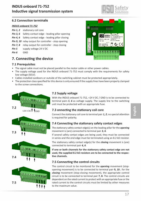
INDUS onboard 71-752 Pin 1, 2 stationary coil corePin 3, 6 Safety contact edge - leading pillar openingPin 4, 6 Safety contact edge - leading pillar closingPin 9, 10 relay output for controller - stop openingPin 7, 8 relay output for controller - stop closingPin 5 supply voltage 24 V DCPin 6 GND
7.2 Supply voltageWith the INDUS onboard 71-752, +24 V DC / GND is to be connected to terminal pairs 5, 6 as voltage supply. The supply line to the switching unit must be protected with an appropriate fuse.
7.3 onnecting the stationary coil coreConnect the stationary coil core to terminal pair 1, 2; no special attention is required for polarity.
7.4 Connecting the stationary safety contact edgesThe stationary safety contact edge(s) on the leading pillar for the opening movement is (are) connected to terminal pair 3, 6.If several safety contact edges are being used, they must be connected in series and the end edge must be terminated using an 8.2 kΩ resistor. The stationary safety contact edge(s) for the closing movement is (are) connected to terminal pair 4, 6.If one or both channels for the stationary safety contact edge are not used, the supplied 8.2 kΩ resistors are to be connected to the respec-tive channels.
7.5 Connecting the control circuitsThe control circuit to be monitored for the opening movement (stop-opening movement) is to be connected to terminal pair 9, 10 ; for the closing movement (stop-closing movement), the appropriate control circuit is to be connected to terminal pair 7, 8. The control circuits are dependent on the rated current to protect with an appropriate fuse or the rated current to the control circuits must be limited by other measures to the maximum value.
6.2 Connection terminals
109871 2 3 4 5 6
+24 V DC GND7.2
109871 2 3 4 5 6
7.3
109871 2 3 4 5 6
7.4
109871 2 3 4 5 6
7.5
109871 2 3 4 5 6
18
ASO safety contact edges must not be connected in parallel.
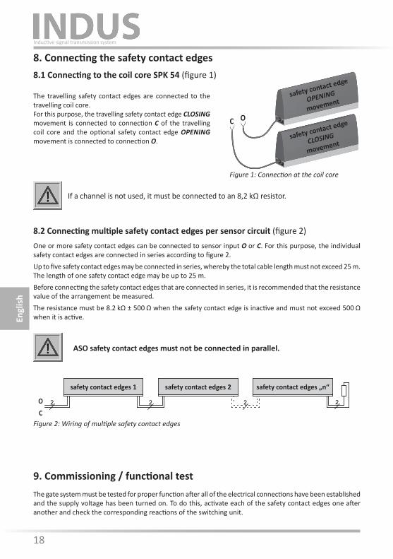
8. Connecting the safety contact edges8.1 Connecting to the coil core SPK 54 (figure 1)
8.2 Connecting multiple safety contact edges per sensor circuit (figure 2)One or more safety contact edges can be connected to sensor input O or C. For this purpose, the individual safety contact edges are connected in series according to figure 2. Up to five safety contact edges may be connected in series, whereby the total cable length must not exceed 25 m.The length of one safety contact edge may be up to 25 m. Before connecting the safety contact edges that are connected in series, it is recommended that the resistance value of the arrangement be measured.The resistance must be 8.2 kΩ ± 500 Ω when the safety contact edge is inactive and must not exceed 500 Ω when it is active.
If a channel is not used, it must be connected to an 8,2 kΩ resistor.
The travelling safety contact edges are connected to the travelling coil core.For this purpose, the travelling safety contact edge CLOSING movement is connected to connection C of the travelling coil core and the optional safety contact edge OPENING movement is connected to connection O.
9. Commissioning / functional testThe gate system must be tested for proper function after all of the electrical connections have been established and the supply voltage has been turned on. To do this, activate each of the safety contact edges one after another and check the corresponding reactions of the switching unit.
Figure 2: Wiring of multiple safety contact edges
Engl
ish
Inductive signal transmission system
safety contact edge
CLOSING
movement
safety contact edge
OPENING
movement
OC
Figure 1: Connection at the coil core
safety contact edges 1 safety contact edges 2 safety contact edges „n“
O
C2222
18 19
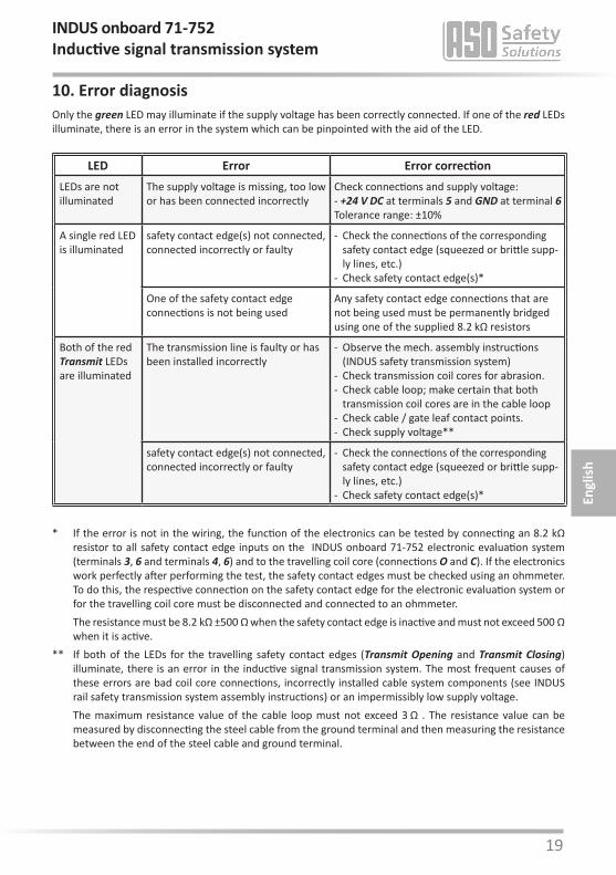
10. Error diagnosisOnly the green LED may illuminate if the supply voltage has been correctly connected. If one of the red LEDs illuminate, there is an error in the system which can be pinpointed with the aid of the LED.
LED Error Error correctionLEDs are not illuminated
The supply voltage is missing, too low or has been connected incorrectly
Check connections and supply voltage:- +24 V DC at terminals 5 and GND at terminal 6Tolerance range: ±10%
A single red LED is illuminated
safety contact edge(s) not connected, connected incorrectly or faulty
- Check the connections of the corresponding safety contact edge (squeezed or brittle supp-ly lines, etc.)
- Check safety contact edge(s)*
One of the safety contact edgeconnections is not being used
Any safety contact edge connections that are not being used must be permanently bridged using one of the supplied 8.2 kΩ resistors
Both of the red Transmit LEDs are illuminated
The transmission line is faulty or has been installed incorrectly
- Observe the mech. assembly instructions (INDUS safety transmission system)
- Check transmission coil cores for abrasion. - Check cable loop; make certain that both
transmission coil cores are in the cable loop- Check cable / gate leaf contact points.- Check supply voltage**
safety contact edge(s) not connected, connected incorrectly or faulty
- Check the connections of the corresponding safety contact edge (squeezed or brittle supp-ly lines, etc.)
- Check safety contact edge(s)*
* If the error is not in the wiring, the function of the electronics can be tested by connecting an 8.2 kΩ resistor to all safety contact edge inputs on the INDUS onboard 71-752 electronic evaluation system (terminals 3, 6 and terminals 4, 6) and to the travelling coil core (connections O and C). If the electronics work perfectly after performing the test, the safety contact edges must be checked using an ohmmeter. To do this, the respective connection on the safety contact edge for the electronic evaluation system or for the travelling coil core must be disconnected and connected to an ohmmeter.
The resistance must be 8.2 kΩ ±500 Ω when the safety contact edge is inactive and must not exceed 500 Ω when it is active.
** If both of the LEDs for the travelling safety contact edges (Transmit Opening and Transmit Closing) illuminate, there is an error in the inductive signal transmission system. The most frequent causes of these errors are bad coil core connections, incorrectly installed cable system components (see INDUS rail safety transmission system assembly instructions) or an impermissibly low supply voltage.
The maximum resistance value of the cable loop must not exceed 3 Ω . The resistance value can be measured by disconnecting the steel cable from the ground terminal and then measuring the resistance between the end of the steel cable and ground terminal.
Engl
ish
INDUS onboard 71-752Inductive signal transmission system

20
12. Technical specificationsSupply voltage UE 24 V DC ±10% IE = 85 mA; Imax = 180mA (100ms)
AssemblyPlug in card for vertically plugging into a controller with Phoenix connector MSTBVA 2,5/11-G-5,08Dimensions: (HxWxD) 82 x 78 x 27 mmProtection class IP00Weight 115 gTemperature range -25°C to +55°CConnection cable cross-sectionsingle- or fine-stranded cable 0,75-1,5 mm2
Certifications (In accordance with INDUS rail 71-242) DIN EN ISO 13849-1:2008 Category 3 PL e MTTFd 170 years, DC 91% Elektronik MTTFd 1616 years, DC 99 % Elektromechanik B10d 1000000 MTTFd 190 years (Nop 52560) Safety device acc. to DIN EN 12978
All voltages connected to the switching unit must be safely isolated! Test report no.:
12 205 399386-000
Certificate no.:44 780 12 399386
EC type-examination no.: 44 205 12 399386
11. Taking out of service and disposalThe products manufactured by ASO are intended solely for commercial use (B2B). At the end of use, the products are to be disposed of according to all local, regional and national regulations. Products can also be returned to ASO, which will then dispose of them properly.
Stationarycontact edge
Travelling contact edge
nominal value Rnom = 8,2 kΩ = 8,2 kΩupper switching point RAO > 12 kΩ > 20 kΩlower switching point RAU < 5 kΩ < 2,5 kΩ
Terminal resistance of the safety contact edges
Nominal current DC 3 A 30 V DCNominal current AC 3 A 30 V AC
Mech. life-time >106 actuations
Relay stages
Stationarycontact edge
Travelling contact edge
Switching off delay (response time) < 10 ms < 30 msSwitching on delay 500 ms (Power on 700 ms)
Safety relay switching times
Engl
ish
Inductive signal transmission system
78
27
70 82
20 21
13. EC declaration of conformity
We hereby declare that the following product:
INDUS onboard 71-752(part no. 1204-0133, serial number format yymmnnnnn)
Inductive transmission device with safety switching system to be used in combination with safety contact edges for preventing dangers at locations on gate systems where there is a risk of crushing and cutting satisfies the relevant essential health and safety requirements of the EC directives and standards listed below on account of its design and construction, as does the version brought to market by us:
EC - machinery directive 2006/42/ECEN ISO 13849-1:2008EN ISO 13849-2:2008EN 61000-6-2:2005EN 61000-6-3:2007
EC - type approvalNotified Body 0044TÜV NORD CERT GmbHLangemarckstraße 20D-45141 EssenEC type-examination no.: 44 205 12 399386(In accordance with INDUS rail 71-242)
This declaration of conformity does not relieve the designer/manufacturer of the machine from his obligation to ensure that the conformity of the entire machine to which this product is attached satisfies the corresponding EC directive.
Manufacturer and Authorised Signatory:ASO, Antriebs- und Steuerungstechnik GmbH,Hansastraße 52, D-59557 Lippstadt / Germany
Engl
ish
INDUS onboard 71-752Inductive signal transmission system

22
22 23
INDUS onboard 71-752Système de transmission de signal inductif
Des modifications techniques et importantes pour le fonctionnement des produits et appareils décrits dans cette documentation sont possibles à tout moment et sans préavis.
Fran
çais
1. Table des matières
1. Table des matières . . . . . . . . . . . . . . . . . . . . . . . . 23
2. Prescriptions générales de sécurité et mesures de protection 24
3. Généralités et Fonctionnement . . . . . . . . . . . . . . . . . 25
4. Utilisation conforme . . . . . . . . . . . . . . . . . . . . . . . 25
5. Composants du système sur le portail. . . . . . . . . . . . . . 26
6. Vue d‘ensemble de l‘appareil . . . . . . . . . . . . . . . . . . 26 6.1 Indicateurs . . . . . . . . . . . . . . . . . . . . . . . . . . . . . . . . . . . . 26 6.2 Bornes de connexion . . . . . . . . . . . . . . . . . . . . . . . . . . . . . . 27
7. Raccordement de l‘appareil . . . . . . . . . . . . . . . . . . . 27 7.1 Conditions . . . . . . . . . . . . . . . . . . . . . . . . . . . . . . . . . . . . 27 7.2 Alimentation. . . . . . . . . . . . . . . . . . . . . . . . . . . . . . . . . . . 27 7.3 Raccordement du noyau de bobine stationnaire . . . . . . . . . . . . . . . 27 7.4 Raccordement des barres palpeuses stationnaires. . . . . . . . . . . . . . 27 7.5 Raccordement des circuits de contrôle . . . . . . . . . . . . . . . . . . . . 27
8. Raccordement des barres palpeuses . . . . . . . . . . . . . . 28 8.1 Raccordement au noyau de bobine SPK 54 . . . . . . . . . . . . . . . . . . 28 8.2 Raccordement de plusieurs barres palpeuses parcircuit de signal . . . . . 28
9. Mise en service et test des fonctions . . . . . . . . . . . . . . . 28
10. Diagnostic d‘erreurs. . . . . . . . . . . . . . . . . . . . . . . . 29
11. Mise hors-service et élimination . . . . . . . . . . . . . . . . . 30
12. Données techniques . . . . . . . . . . . . . . . . . . . . . . . 30
13. Déclaration de conformité CE . . . . . . . . . . . . . . . . . . 31
24
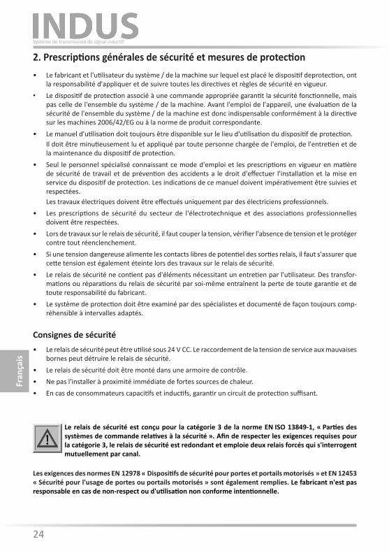
2. Prescriptions générales de sécurité et mesures de protection • Le fabricant et l'utilisateur du système / de la machine sur lequel est placé le dispositif deprotection, ont
la responsabilité d'appliquer et de suivre toutes les directives et règles de sécurité en vigueur.• Le dispositif de protection associé à une commande appropriée garantit la sécurité fonctionnelle, mais
pas celle de l'ensemble du système / de la machine. Avant l'emploi de l'appareil, une évaluation de la sécurité de l'ensemble du système / de la machine est donc indispensable conformément à la directive sur les machines 2006/42/EG ou à la norme de produit correspondante.
• Le manuel d’utilisation doit toujours être disponible sur le lieu d'utilisation du dispositif de protection. Il doit être minutieusement lu et appliqué par toute personne chargée de l'emploi, de l'entretien et de
la maintenance du dispositif de protection.• Seul le personnel spécialisé connaissant ce mode d'emploi et les prescriptions en vigueur en matière
de sécurité de travail et de prévention des accidents a le droit d'effectuer l'installation et la mise en service du dispositif de protection. Les indications de ce manuel doivent impérativement être suivies et respectées.
Les travaux électriques doivent être effectués uniquement par des électriciens professionnels.• Les prescriptions de sécurité du secteur de l'électrotechnique et des associations professionnelles
doivent être respectées.• Lors de travaux sur le relais de sécurité, il faut couper la tension, vérifier l'absence de tension et le protéger
contre tout réenclenchement.• Si une tension dangereuse alimente les contacts libres de potentiel des sorties relais, il faut s'assurer que
cette tension est également éteinte lors des travaux sur le relais de sécurité.• Le relais de sécurité ne contient pas d'éléments nécessitant un entretien par l'utilisateur. Des transfor-
mations ou réparations du relais de sécurité par soi-même entraînent la perte de toute garantie et de toute responsabilité du fabricant.
• Le système de protection doit être examiné par des spécialistes et documenté de façon toujours comp-réhensible à intervalles adaptés.
Consignes de sécurité • Le relais de sécurité peut être utilisé sous 24 V CC. Le raccordement de la tension de service aux mauvaises
bornes peut détruire le relais de sécurité.• Le relais de sécurité doit être monté dans une armoire de contrôle.• Ne pas l'installer à proximité immédiate de fortes sources de chaleur.• En cas de consommateurs capacitifs et inductifs, garantir un circuit de protection suffisant.
Le relais de sécurité est conçu pour la catégorie 3 de la norme EN ISO 13849-1, « Parties des systèmes de commande relatives à la sécurité ». Afin de respecter les exigences requises pour la catégorie 3, le relais de sécurité est redondant et emploie deux relais forcés qui s'interrogent mutuellement par canal.
Les exigences des normes EN 12978 « Dispositifs de sécurité pour portes et portails motorisés » et EN 12453 « Sécurité pour l'usage de portes ou portails motorisés » sont également remplies. Le fabricant n'est pas responsable en cas de non-respect ou d'utilisation non conforme intentionnelle.
Fran
çais
Système de transmission de signal inductif
24 25
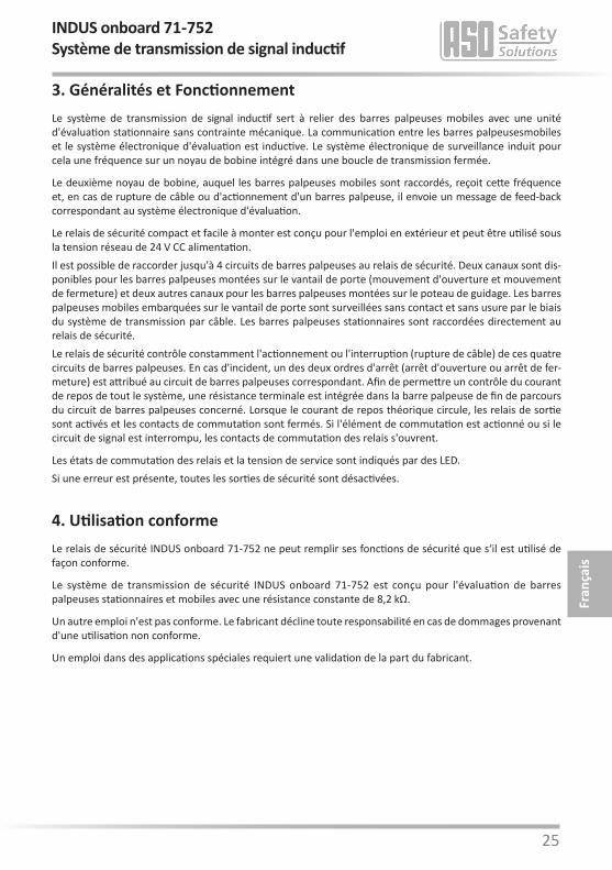
3. Généralités et FonctionnementLe système de transmission de signal inductif sert à relier des barres palpeuses mobiles avec une unité d'évaluation stationnaire sans contrainte mécanique. La communication entre les barres palpeusesmobiles et le système électronique d'évaluation est inductive. Le système électronique de surveillance induit pour cela une fréquence sur un noyau de bobine intégré dans une boucle de transmission fermée.
Le deuxième noyau de bobine, auquel les barres palpeuses mobiles sont raccordés, reçoit cette fréquence et, en cas de rupture de câble ou d'actionnement d'un barres palpeuse, il envoie un message de feed-back correspondant au système électronique d'évaluation.
Le relais de sécurité compact et facile à monter est conçu pour l'emploi en extérieur et peut être utilisé sous la tension réseau de 24 V CC alimentation. Il est possible de raccorder jusqu'à 4 circuits de barres palpeuses au relais de sécurité. Deux canaux sont dis-ponibles pour les barres palpeuses montées sur le vantail de porte (mouvement d'ouverture et mouvement de fermeture) et deux autres canaux pour les barres palpeuses montées sur le poteau de guidage. Les barres palpeuses mobiles embarquées sur le vantail de porte sont surveillées sans contact et sans usure par le biais du système de transmission par câble. Les barres palpeuses stationnaires sont raccordées directement au relais de sécurité. Le relais de sécurité contrôle constamment l'actionnement ou l'interruption (rupture de câble) de ces quatre circuits de barres palpeuses. En cas d'incident, un des deux ordres d'arrêt (arrêt d'ouverture ou arrêt de fer-meture) est attribué au circuit de barres palpeuses correspondant. Afin de permettre un contrôle du courant de repos de tout le système, une résistance terminale est intégrée dans la barre palpeuse de fin de parcours du circuit de barres palpeuses concerné. Lorsque le courant de repos théorique circule, les relais de sortie sont activés et les contacts de commutation sont fermés. Si l'élément de commutation est actionné ou si le circuit de signal est interrompu, les contacts de commutation des relais s'ouvrent.
Les états de commutation des relais et la tension de service sont indiqués par des LED.Si une erreur est présente, toutes les sorties de sécurité sont désactivées.
4. Utilisation conformeLe relais de sécurité INDUS onboard 71-752 ne peut remplir ses fonctions de sécurité que s‘il est utilisé de façon conforme.
Le système de transmission de sécurité INDUS onboard 71-752 est conçu pour l'évaluation de barres palpeuses stationnaires et mobiles avec une résistance constante de 8,2 kΩ.
Un autre emploi n'est pas conforme. Le fabricant décline toute responsabilité en cas de dommages provenant d'une utilisation non conforme.
Un emploi dans des applications spéciales requiert une validation de la part du fabricant.
Fran
çais
INDUS onboard 71-752Système de transmission de signal inductif
26
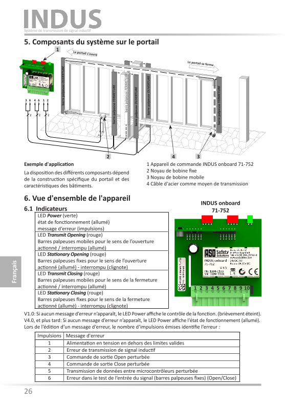
6. Vue d'ensemble de l'appareil6.1 Indicateurs
Impulsions Message d'erreur1 Alimentation en tension en dehors des limites valides2 Erreur de transmission de signal inductif3 Commande de sortie Open perturbée4 Commande de sortie Close perturbée5 Transmission de données entre microcontrôleurs perturbée6 Erreur dans le test de l‘entrée du signal (barres palpeuses fixes) (Open/Close)
V1.0: Si aucun message d’erreur n’apparaît, le LED Power affiche le contrôle de la fonction. (brièvement éteint).V4.0, et plus tard: Si aucun message d’erreur n’apparaît, le LED Power affiche l‘état de fonctionnement (allumé).Lors de l‘édition d‘un message d‘erreur, le nombre d‘impulsions émises identifie l‘erreur :
5. Composants du système sur le portail
ISK 71-24
Transmit OpeningStationary Opening
TransmitStationary
Power
ISK 71-242
33 11 10 1 2
2 2 2
2 4 3
Le portail s'ouvre
Le portail se ferme
barr
e pa
lpeu
se O
UVE
RTU
RE
barr
e pa
lpeu
se O
UVE
RTU
RE
barr
e pa
lpeu
se O
UVE
RTU
RE
barr
e pa
lpeu
se F
ERM
ETU
RE
barr
e pa
lpeu
se F
ERM
ETU
RE
barr
e pa
lpeu
se F
ERM
ETU
RE
1 Appareil de commande INDUS onboard 71-7522 Noyau de bobine fixe3 Noyau de bobine mobile4 Câble d'acier comme moyen de transmission
Exemple d'applicationLa disposition des différents composants dépend de la construction spécifique du portail et des caractéristiques des bâtiments.
Fran
çais
Système de transmission de signal inductif
LED Power (verte)état de fonctionnement (allumé)message d‘erreur (impulsions)LED Transmit Opening (rouge)Barres palpeuses mobiles pour le sens de l’ouvertureactionné / interrompu (allumé)LED Stationary Opening (rouge)Barres palpeuses fixes pour le sens de l’ouvertureactionné (allumé) - interrompu (clignote)LED Transmit Closing (rouge)Barres palpeuses mobiles pour le sens de la fermetureactionné / interrompu (allumé)LED Stationary Closing (rouge)Barres palpeuses fixes pour le sens de la fermetureactionné (allumé) - interrompu (clignote)
1
3 216 4 6
INDUS onboard 71-752
109871 2 3 4 5 6
26 27
Fran
çais
INDUS onboard 71-752Système de transmission de signal inductif
7. Raccordement de l‘appareil7.1 Conditions• La pose des câbles de signal ne doit pas se faire en parallèle du câblage de la commande ou d’autres câblages.• L‘alimentation de l‘INDUS onboard 71-752 doit répondre aux exigences de la très basse tension de protection (TBTP).• Les câbles posés en extérieur ou en dehors de l‘armoire électrique doivent être protégés de façon appropriée.• L‘indice de protection indiqué pour l‘appareil n‘est garanti que si les câbles d‘alimentation sont fixés correctement dans les presse-étoupe.
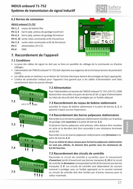
INDUS onboard 71-752 Pin 1, 2 noyau de bobine fixePin 3, 6 barre palp. poteau de guidage ouverturePin 4, 6 barre palp. poteau de guidage fermeture Pin 9, 10 sortie relais commande arrêt d’ouverturePin 7, 8 sortie relais commande arrêt de fermeturePin 5 alimentation 24 V CCPin 6 GND
7.2 AlimentationPour l‘alimentation en tension de l‘INDUS onboard 71-752 +24 V CC / GND doivent être raccordés à la paire de bornes 5 / 6. La ligne d‘alimentation au relais de sécurité doit être protégée par un fusible adéquat.
7.3 Raccordement du noyau de bobine stationnaireaccordez le noyau de bobine stationnaire à la paire de bornes 1, 2, la polarité n‘ayant aucune importance.
7.4 Raccordement des barres palpeuses stationnairesRaccordez la ou les barres palpeuses stationnaires montées sur le poteau de guidage côté ouverture à la paire de bornes 3, 6.Si plusieurs barres palpeuses sont prévues, elles doivent être montées en série et la dernière doit être raccordée à une résistance terminale de 8,2 kΩ. Raccordez la ou les barres palpeuses stationnaires coté fermeture à la paire de bornes 4, 6.Si un ou même les deux canaux pour les barres palpeuses stationnaires ne sont pas utilisés, ils doivent être pontés avec les résistances de 8,2 kΩ fournies.
7.5 Raccordement des circuits de contrôleRaccordez le circuit de contrôle à surveiller pour le mouvement d‘ouverture (arrêt d‘ouverture) aux bornes marquées 9, 10 et le circuit de contrôle de fermeture correspondant (arrêt de fermeture) aux bornes marquées 7, 8. Les circuits de contrôle sont dépendants du courant nominal à protéger avec un fusible approprié ou le courant nominal au circuits de contrôle doit être limitée par d‘autres mesures pour la valeur maximale.
6.2 Bornes de connexion
109871 2 3 4 5 6
+24 V CC GND7.2
109871 2 3 4 5 6
7.3
109871 2 3 4 5 6
7.4
109871 2 3 4 5 6
7.5
109871 2 3 4 5 6
28
2222
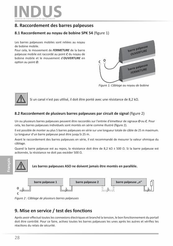
8. Raccordement des barres palpeuses8.1 Raccordement au noyau de bobine SPK 54 (figure 1)
8.2 Raccordement de plusieurs barres palpeuses par circuit de signal (figure 2)
Un ou plusieurs barres palpeuses peuvent être raccordés sur l'entrée d'émetteur de signaux O ou C. Pour cela, les barres palpeuses individuels sont montés en série comme illustré (figure 2). Il est possible de monter au plus 5 barres palpeuses en série sur une longueur totale de câble de 25 m maximum. La longueur d‘un barre palpeuse peut être jusqu‘à 25 m.Avant le raccordement des barres palpeuses en série, il est recommandé de mesurer la valeur ohmique du câblage.Quand la barre palpeuse est au repos, la résistance doit être de 8,2 kΩ ± 500 Ω. Si la barre palpeuse est actionnée, la résistance ne doit pas excéder 500 Ω.
Si un canal n'est pas utilisé, il doit être ponté avec une résistance de 8,2 kΩ.
Les barres palpeuses mobiles sont reliées au noyau de bobine mobile.Pour cela, le mouvement de FERMETURE de la barre palpeuse mobile est raccordé au point C du noyau de bobine mobile et le mouvement d'OUVERTURE en option au point O.
9. Mise en service / test des fonctionsAprès avoir effectué toutes les connexions électriques et branché la tension, le bon fonctionnement du portail doit être contrôlé. Pour ce faire, activez toutes les barres palpeuses les unes après les autres et vérifiez les réactions du relais de sécurité.
Les barres palpeuses ASO ne doivent jamais être montés en parallèle.
Figure 2 : Câblage de plusieurs barres palpeuses
barre palpeuse 1 barre palpeuse 2 barre palpeuse „n“
O
C
Fran
çais
Système de transmission de signal inductif
barre palpeuse
FERMETURE
barre palpeuse
OUVERTURE
OC
Figure 1: Câblage au noyau de bobine
28 29
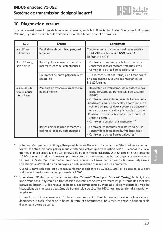
10. Diagnostic d'erreursSi le câblage est correct, lors de la mise sous tension, seule la LED verte doit briller. Si une des LED rouges s'allume, il y a une erreur dans le système que la LED allumée permet de localiser.
LED Erreur CorrectionLes LED ne brillent pas
Pas d'alimentation, trop peu, mal branchée
Contrôler les raccordements et l'alimentation :- +24 V CC aux borne 5 e GND borne 6Tolérance : ±10 %
Une LED rouge isolée brille
Barres palpeuses non raccordées, mal raccordées ou défectueuses
- Contrôler les raccords de la barre palpeuse concernée (câbles coincés, fragilisés, etc.)
- Contrôler la ou les barres palpeuses*
Un raccord de barre palpeuse n'est pas utilisé
Si un raccord n'est pas utilisé, il doit être ponté en permanence avec une des résistances de 8,2 kΩ fournies
Les deux LED rouges Trans-mit brillent
Parcours de transmission perturbé ou mal monté
- Respecter les instructions de montage méca-nique (système de transmission de sécurité INDUS)
- Contrôler l'usure des noyaux de transmission. - Contrôler la boucle du câble ; il convient ici de
veiller à ce que les deux noyaux de transmissi-on se trouvent au sein de la boucle du câble
- Contrôler les points de contact entre câble et corps du portail.
- Contrôler la tension d'alimentation**
Barres palpeuses non raccordées, mal raccordées ou défectueuses
- Contrôler les raccords de la barre palpeuse concernée (câbles coincés, fragilisés, etc.)
- Contrôler la ou les barres palpeuses*
* Si l'erreur n'est pas dans le câblage, il est possible de vérifier le fonctionnement de l'électronique en pontant toutes les entrées de barre palpeuse sur le système électronique d'évaluation de l'INDUS onboard 71-752 (bornes 3, 6 et bornes 4, 6) et sur le noyau de bobine mobile (raccords O et C) avec une résistance de 8,2 kΩ chacune. Si alors, l'électronique fonctionne correctement, les barres palpeuses doivent être vérifiées à l'aide d'un ohmmètre. Pour cela, coupez la liaison concernée de la barre palpeuse à l'électronique d'évaluation ou au noyau de bobine mobile et reliez-la à un ohmmètre.
Quand la barre palpeuse est au repos, la résistance doit être de 8,2 kΩ ±500 Ω. Si la barre palpeuse est actionnée, la résistance ne doit pas excéder 500 Ω.
** Si les deux LED des barres palpeuses mobiles (Transmit Opening et Transmit Closing) brillent, il y a une erreur dans le système de transmission inductif. Les sources d'erreurs les plus courantes sont des mauvaises liaisons sur les noyaux de bobine, des composants du système à câble mal installés (voir les instructions de montage du système de transmission de sécurité INDUS) ou une tension d'alimentation trop basse.
La boucle du câble peut avoir une résistance maximale de 3 Ω. Pour déterminer la valeur de la résistance, débranchez le câble d'acier de la borne de terre et effectuez ensuite la mesure entre le bout du câble d'acier et la borne de terre.
Fran
çais
INDUS onboard 71-752Système de transmission de signal inductif
30
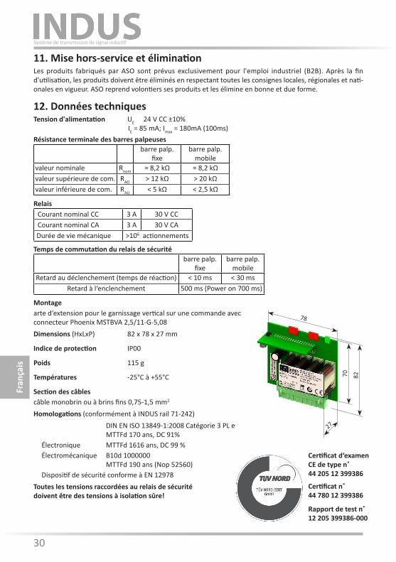
12. Données techniquesTension d'alimentation UE 24 V CC ±10% IE = 85 mA; Imax = 180mA (100ms)
Montagearte d‘extension pour le garnissage vertical sur une commande avec connecteur Phoenix MSTBVA 2,5/11-G-5,08Dimensions (HxLxP) 82 x 78 x 27 mm
Indice de protection IP00
Poids 115 g
Températures -25°C à +55°C
Section des câblescâble monobrin ou à brins fins 0,75-1,5 mm2
Homologations (conformément à INDUS rail 71-242) DIN EN ISO 13849-1:2008 Catégorie 3 PL e MTTFd 170 ans, DC 91% Électronique MTTFd 1616 ans, DC 99 % Électromécanique B10d 1000000 MTTFd 190 ans (Nop 52560) Dispositif de sécurité conforme à EN 12978Toutes les tensions raccordées au relais de sécurité doivent être des tensions à isolation sûre!
Rapport de test n˚12 205 399386-000
Certificat n˚44 780 12 399386
Certificat d‘examen CE de type n˚ 44 205 12 399386
11. Mise hors-service et éliminationLes produits fabriqués par ASO sont prévus exclusivement pour l'emploi industriel (B2B). Après la fin d'utilisation, les produits doivent être éliminés en respectant toutes les consignes locales, régionales et nati-onales en vigueur. ASO reprend volontiers ses produits et les élimine en bonne et due forme.
barre palp.fixe
barre palp.mobile
valeur nominale Rnom = 8,2 kΩ = 8,2 kΩvaleur supérieure de com. RAO > 12 kΩ > 20 kΩvaleur inférieure de com. RAU < 5 kΩ < 2,5 kΩ
Résistance terminale des barres palpeuses
Courant nominal CC 3 A 30 V CCCourant nominal CA 3 A 30 V CADurée de vie mécanique >106 actionnements
Relais
barre palp. fixe
barre palp.mobile
Retard au déclenchement (temps de réaction) < 10 ms < 30 msRetard à l‘enclenchement 500 ms (Power on 700 ms)
Temps de commutation du relais de sécurité
Fran
çais
Système de transmission de signal inductif
78
27
70 82
30 31
13. Déclaration de conformité CE
Nous déclarons par la présente que le produit:
INDUS onboard 71-752(article n° 1204-0133, format de numéro de série yymmnnnnn)
dispositifs de transmission inductifs avec système de commutation de sécurité pour la combinaison de barres palpeuses dans le but d'éviter les risques d'écrasement et de cisaillement sur les systèmes de portails, de par leur conception et leur construction, ainsi que dans les modèles mis en circulation par nos soins, répondent aux exigences de base pour la sécurité et la santé des directives et normes CE suivantes :
Directive CE sur les machines 2006/42/CEEN ISO 13849-1:2008EN ISO 13849-2:2008EN 61000-6-2:2005EN 61000-6-3:2007
Examen CE du modèle typeNotified Body 0044TÜV NORD CERT GmbHLangemarckstrasse 20D-45141 EssenCertificat d‘examen CE de type n˚ 44 205 12 399386(conformément à INDUS rail 71-242)
Cette déclaration de conformité ne délie pas le constructeur/fabricant de la machine de son obligation d'assurer la conformité de l'ensemble de la machine à laquelle ce produit est apposé selon la directive CE.
Fabricant et responsable documentation :ASO, Antriebs- und Steuerungstechnik GmbH,Hansastraße 52, D-59557 Lippstadt
Fran
çais
INDUS onboard 71-752Système de transmission de signal inductif
32
Antriebs- und SteuerungstechnikHansastraße 52 • D-59557 Lippstadt Tel.: +49 2941/9793-0 • Fax: +49 (0) 2941/9793 142www.asosafety.com • e-mail: [email protected]
12.DB.04.201 Betriebsanleitung Rev 01 Technische Änderungen vorbehalten.Für Irrtümer und Druckfehler kann keine Haftung übernommen werden.Diese Betriebsanleitung ist für folgende Versionsstände gültig:von V 1.0 bis V 4.0
12.DB.04.201 Operating Manual Rev 01 Subject to technical modifications.No liability can be assumed for errors or misprints.This operating manual is valid for the following versions:from V 1.0 to V 4.0
12.DB.04.201 Manuel d’utilisation Rév 01 Sous réserve de modifications techniques.Nous déclinons toute responsabilité en cas d‘erreurs et de fautes d‘impression.Ce mode d’emploi n’est valable que pour les versions suivantes:de V 1.0 à V 4.0
Deutsch
English
Français
Induktives Signalübertragungssystem / Inductive signal transmission system / Système de transmission de signal inductif