Embed Size (px)
Citation preview

Abscheider mit Sicherheit einbauen ab Seite 2
Einbauanleitung für ACO Leichtflüssigkeits- und
Fettabscheider aus Stahl- oder Polymerbeton
Install Separator safely from page 18
Installation instructions for ACO light fluid and grease
separators from reinforced or polymer concrete
Monter en toute sécurité un séparateur à partir de la page 34
Instructions de montage pour séparateur de graisses
et séparateur d'hydrocarbure ACO en béton armé et
béton polymère
2 von 56
Einbauanleitung für Abscheideranlagen
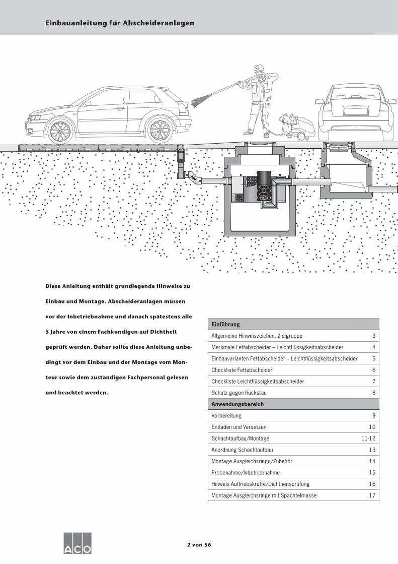
Diese Anleitung enthält grundlegende Hinweise zu
Einbau und Montage. Abscheideranlagen müssen
vor der Inbetriebnahme und danach spätestens alle
5 Jahre von einem Fachkundigen auf Dichtheit
geprüft werden. Daher sollte diese Anleitung unbe-
dingt vor dem Einbau und der Montage vom Mon-
teur sowie dem zuständigen Fachpersonal gelesen
und beachtet werden.
Einführung
Allgemeine Hinweiszeichen, Zielgruppe 3
Merkmale Fettabscheider – Leichtflüssigkeitsabscheider 4
Einbauvarianten Fettabscheider – Leichtflüssigkeitsabscheider 5
Checkliste Fettabscheider 6
Checkliste Leichtflüssigkeitsabscheider 7
Schutz gegen Rückstau 8
Anwendungsbereich
Vorbereitung 9
Entladen und Versetzen 10
Schachtaufbau/Montage 11-12
Anordnung Schachtaufbau 13
Montage Ausgleichsringe/Zubehör 14
Probenahme/Inbetriebnahme 15
Hinweis Auftriebskräfte/Dichtheitsprüfung 16
Montage Ausgleichsringe mit Spachtelmasse 17
3 von 56
Einbauanleitung für Abscheideranlagen
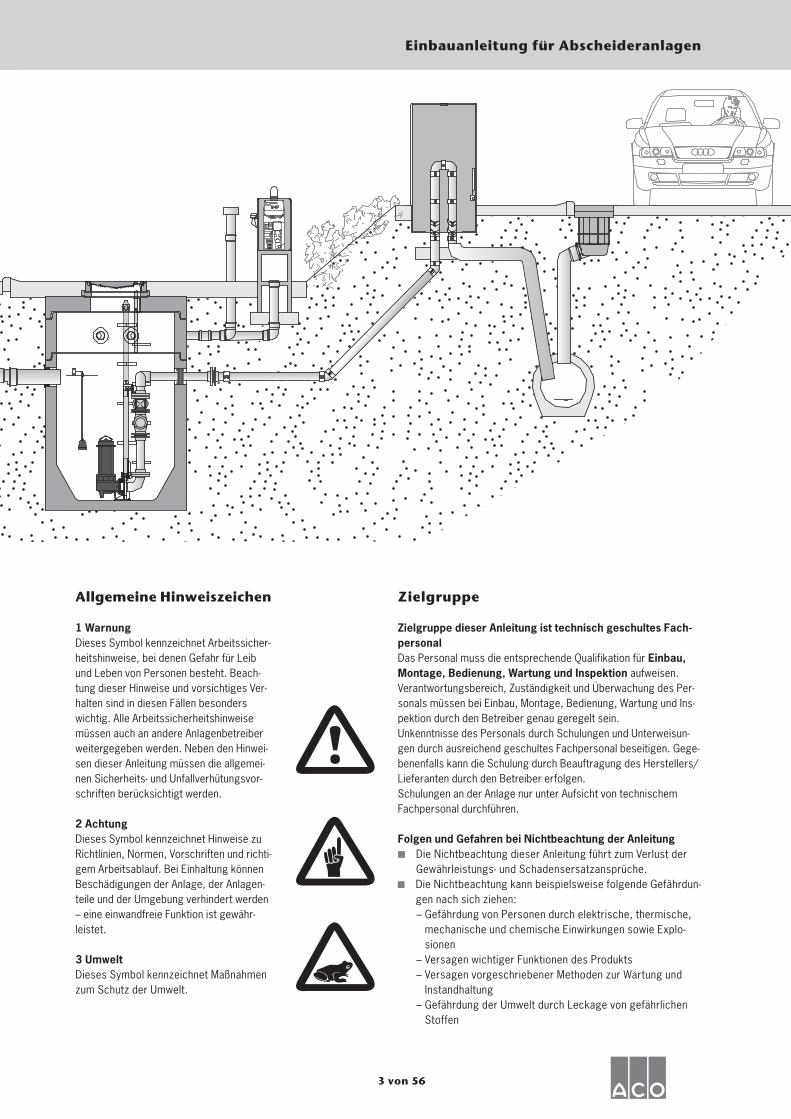
Allgemeine Hinweiszeichen
1 WarnungDieses Symbol kennzeichnet Arbeitssicher-heitshinweise, bei denen Gefahr für Leib und Leben von Personen besteht. Beach-tung dieser Hinweise und vorsichtiges Ver-halten sind in diesen Fällen besonders wichtig. Alle Arbeitssicherheitshinweise müssen auch an andere Anlagenbetreiber weitergegeben werden. Neben den Hinwei-sen dieser Anleitung müssen die allgemei-nen Sicherheits- und Unfallverhütungsvor-schriften berücksichtigt werden.
2 AchtungDieses Symbol kennzeichnet Hinweise zu Richtlinien, Normen, Vorschriften und richti-gem Arbeitsablauf. Bei Einhaltung können Beschädigungen der Anlage, der Anlagen-teile und der Umgebung verhindert werden – eine einwandfreie Funktion ist gewähr-leistet.
3 UmweltDieses Symbol kennzeichnet Maßnahmen zum Schutz der Umwelt.
Zielgruppe
Zielgruppe dieser Anleitung ist technisch geschultes Fach-personalDas Personal muss die entsprechende Qualifikation für Einbau, Montage, Bedienung, Wartung und Inspektion aufweisen.Verantwortungsbereich, Zuständigkeit und Überwachung des Per-sonals müssen bei Einbau, Montage, Bedienung, Wartung und Ins-pektion durch den Betreiber genau geregelt sein.Unkenntnisse des Personals durch Schulungen und Unterweisun-gen durch ausreichend geschultes Fachpersonal beseitigen. Gege-benenfalls kann die Schulung durch Beauftragung des Herstellers/Lieferanten durch den Betreiber erfolgen.Schulungen an der Anlage nur unter Aufsicht von technischem Fachpersonal durchführen.
Folgen und Gefahren bei Nichtbeachtung der Anleitung▪ Die Nichtbeachtung dieser Anleitung führt zum Verlust der
Gewährleistungs- und Schadensersatzansprüche. Die Nichtbeachtung kann beispielsweise folgende Gefährdun-
gen nach sich ziehen: – Gefährdung von Personen durch elektrische, thermische,
mechanische und chemische Einwirkungen sowie Explo- sionen
– Versagen wichtiger Funktionen des Produkts – Versagen vorgeschriebener Methoden zur Wartung und
Instandhaltung – Gefährdung der Umwelt durch Leckage von gefährlichen
Stoffen

4 von 56
Einbauanleitung für Abscheideranlagen
Merkmale Fettabscheider – Leichtflüssigkeitsabscheider
Fettabscheider: Lipumax-C-FST kein Schwimmer (ohne selbsttätigen
Verschluss) Auslaufgarnitur (kein Geruchsver-
schluss) Sammelbehälter Werkstoff Stahlbeton
mit PE-HD Inliner oder Stahlbeton beschichtet
Leichflüssigkeitsabscheider: Oleopator-C-OST, Oleosmart-C-OST
Schwimmer (selbsttätiger Verschluss) Auslaufgarnitur (mit Geruchsver-
schluss) Sammelbehälter Werkstoff Stahlbeton
beschichtet, Stahlbeton mit PE-HD Inli-ner
Innenbeschichtung bzw. Innenmaterial Grundschacht
Beschichtung
(anthrazit)
Inliner PE-HD
(schwarz)
Optional als Inliner PE-
HD (Schwarz)
Innenbeschichtung bzw. Innenmaterial Grundschacht
Beschichtung Standard
(blau)
Zulauf- garnitur
Auslauf- garnitur
Auslauf- garnitur
Schwimmer
Zulauf- garnitur
5 von 56
Einbauanleitung für Abscheideranlagen
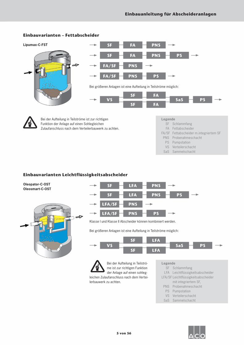
Einbauvarianten – Fettabscheider
Lipumax-C-FST
PS
SF FA PNS
SF FA PNS
FA/SF PNS
FA/SF PNS PS
Bei größeren Anlagen ist eine Aufteilung in Teilströme möglich:
VSSF FA
SF FASaS PS
Bei der Aufteilung in Teilströme ist zur richtigen Funktion der Anlage auf einen Sohlegleichen Zulaufanschluss nach dem Verteilerbauwerk zu achten.
Legende SF Schlammfang FA Fettabscheider FA/SF Fettabscheider m.integriertem SF PNS Probenahmeschacht PS Pumpstation VS Verteilerschacht SaS Sammelschacht
Oleopator-C-OSTOleosmart-C-OST
PS
Einbauvarianten Leichtflüssigkeitsabscheider
SF LFA PNS
SF LFA PNS
LFA/SF PNS
LFA/SF PNS PS
Klasse I und Klasse II Abscheider können kombiniert werden.
Bei größeren Anlagen ist eine Aufteilung in Teilströme möglich:
VSSF LFA
SF LFASaS PS
Bei der Aufteilung in Teilströ-me ist zur richtigen Funktion der Anlage auf einen sohleg-
leichen Zulaufanschluss nach dem Vertei-lerbauwerk zu achten.
Legende SF Schlammfang LFA LeichtflüssigkeitsabscheiderL FA/SF Leichtflüssigkeitsabscheider mit integriertem SF, PNS Probenahmeschacht PS Pumpstation VS Verteilerschacht SaS Sammelschacht
6 von 56
Einbauanleitung für Abscheideranlagen
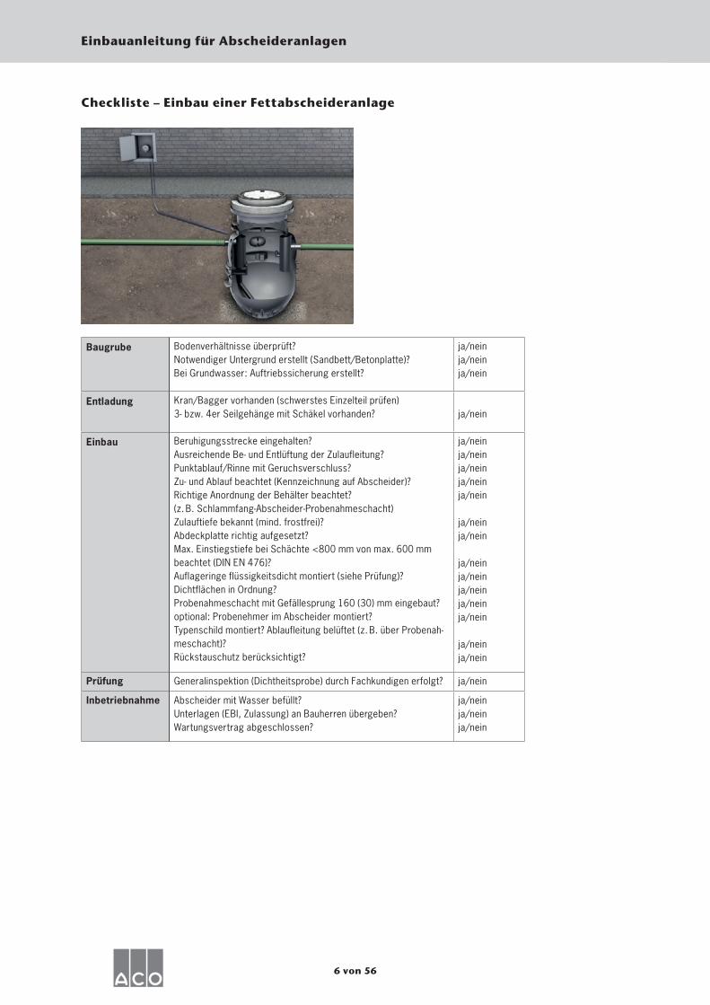
Baugrube Bodenverhältnisse überprüft?Notwendiger Untergrund erstellt (Sandbett/Betonplatte)? Bei Grundwasser: Auftriebssicherung erstellt?
ja/neinja/neinja/nein
Entladung Kran/Bagger vorhanden (schwerstes Einzelteil prüfen)3- bzw. 4er Seilgehänge mit Schäkel vorhanden? ja/nein
Einbau Beruhigungsstrecke eingehalten?Ausreichende Be- und Entlüftung der Zulaufleitung?Punktablauf/Rinne mit Geruchsverschluss?Zu- und Ablauf beachtet (Kennzeichnung auf Abscheider)?Richtige Anordnung der Behälter beachtet?(z. B. Schlammfang-Abscheider-Probenahmeschacht)Zulauftiefe bekannt (mind. frostfrei)?Abdeckplatte richtig aufgesetzt?Max. Einstiegstiefe bei Schächte <800 mm von max. 600 mmbeachtet (DIN EN 476)?Auflageringe flüssigkeitsdicht montiert (siehe Prüfung)?Dichtflächen in Ordnung?Probenahmeschacht mit Gefällesprung 160 (30) mm eingebaut?optional: Probenehmer im Abscheider montiert?Typenschild montiert? Ablaufleitung belüftet (z. B. über Probenah-meschacht)?Rückstauschutz berücksichtigt?
ja/neinja/neinja/neinja/neinja/nein
ja/neinja/nein
ja/neinja/neinja/neinja/neinja/nein
ja/neinja/nein
Prüfung Generalinspektion (Dichtheitsprobe) durch Fachkundigen erfolgt? ja/nein
Inbetriebnahme Abscheider mit Wasser befüllt?Unterlagen (EBI, Zulassung) an Bauherren übergeben?Wartungsvertrag abgeschlossen?
ja/neinja/neinja/nein
Checkliste – Einbau einer Fettabscheideranlage
7 von 56
Einbauanleitung für Abscheideranlagen
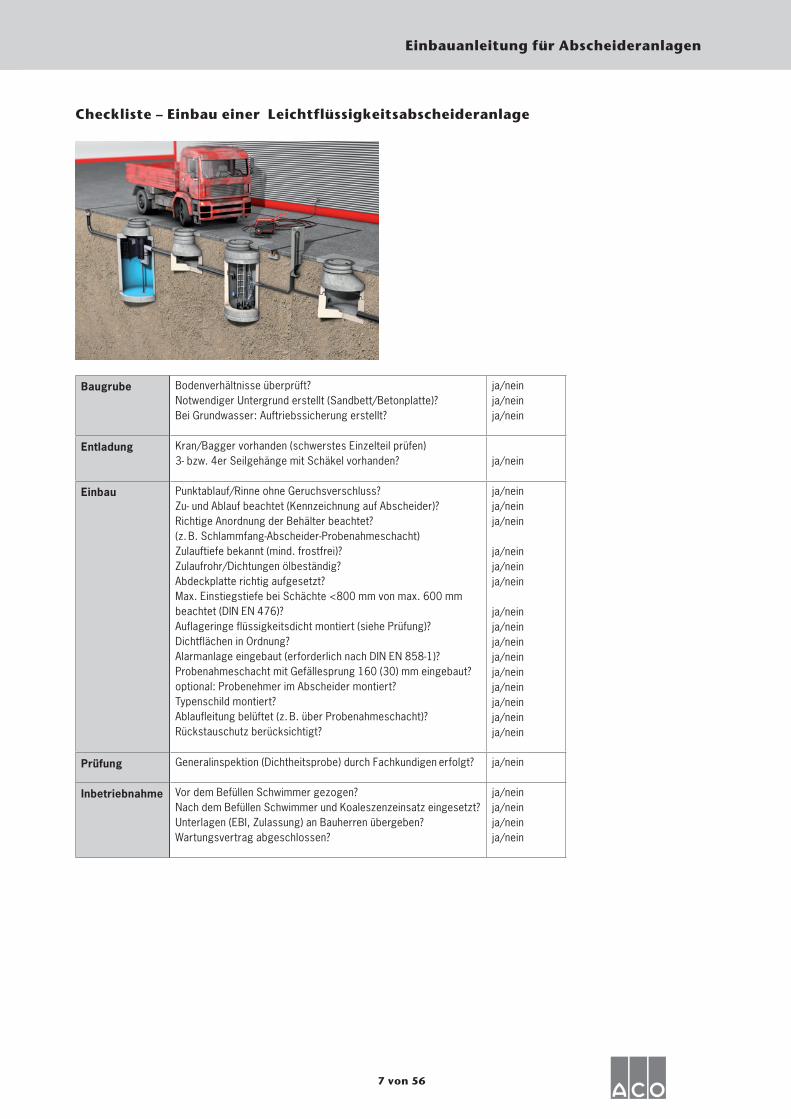
Baugrube Bodenverhältnisse überprüft?Notwendiger Untergrund erstellt (Sandbett/Betonplatte)? Bei Grundwasser: Auftriebssicherung erstellt?
ja/neinja/neinja/nein
Entladung Kran/Bagger vorhanden (schwerstes Einzelteil prüfen)3- bzw. 4er Seilgehänge mit Schäkel vorhanden? ja/nein
Einbau Punktablauf/Rinne ohne Geruchsverschluss?Zu- und Ablauf beachtet (Kennzeichnung auf Abscheider)?Richtige Anordnung der Behälter beachtet?(z. B. Schlammfang-Abscheider-Probenahmeschacht)Zulauftiefe bekannt (mind. frostfrei)?Zulaufrohr/Dichtungen ölbeständig?Abdeckplatte richtig aufgesetzt?Max. Einstiegstiefe bei Schächte <800 mm von max. 600 mmbeachtet (DIN EN 476)?Auflageringe flüssigkeitsdicht montiert (siehe Prüfung)?Dichtflächen in Ordnung?Alarmanlage eingebaut (erforderlich nach DIN EN 858-1)?Probenahmeschacht mit Gefällesprung 160 (30) mm eingebaut?optional: Probenehmer im Abscheider montiert?Typenschild montiert?Ablaufleitung belüftet (z. B. über Probenahmeschacht)?Rückstauschutz berücksichtigt?
ja/neinja/neinja/nein
ja/neinja/neinja/nein
ja/neinja/neinja/neinja/neinja/neinja/neinja/neinja/nein ja/nein
Prüfung Generalinspektion (Dichtheitsprobe) durch Fachkundigen erfolgt? ja/nein
Inbetriebnahme Vor dem Befüllen Schwimmer gezogen?Nach dem Befüllen Schwimmer und Koaleszenzeinsatz eingesetzt?Unterlagen (EBI, Zulassung) an Bauherren übergeben? Wartungsvertrag abgeschlossen?
ja/neinja/neinja/neinja/nein
Checkliste – Einbau einer Leichtflüssigkeitsabscheideranlage
8 von 56
Einbauanleitung für Abscheideranlagen
Schutz gegen Rückstau
Der Einbau muss durch einen geeigneten Fachbetrieb unter Berücksichtigung der jeweils geltenden Normen und Vorschrif-ten vorgenommen werden.
KanalanschlussDie Abscheideranlagen sind an die Schmutzwasser- oder Misch-wasserkanalisation anzuschlie-ßen. Andere Anschlussweisen benötigen die Genehmigung der
zuständigen Behörde. Beim Kanalan-schluss sind u. a. die Normen DIN EN 12056, DIN EN 752 und DIN 1986-100 einzuhalten. Hier gilt ein besonderer Augenmerk der Einbaulage des Abschei-ders zur sogenannten Rückstauebene (normalerweise Straßenoberkante an der
Anschlussstelle). Liegt der Abscheider mit seinem Ruhewasserspiegel unterhalb der Rückstauebene so sind die entsprechen-den Maßnahmen (z. B. Einbau einer Pump-station mit Rückstauschleife) zum Schutz gegen Rückstau vorzusehen. Beim Verfül-len und Unterbauen der Anschluss- und Verbindungsleitungen ist die DIN 4033 zu beachten. Soweit erforderlich ist Korrosi-onsschutz für erdverlegte Leitungen vor-zusehen. DIN 30672 Teil 1 ist zu beach-ten. Ablaufleitungen von Abscheideranla-gen sind mit einem Absaugeschutz zu ver-sehen (z. B. durch einen Schacht oder eine entsprechende Belüftung der Ablauf-leitung; siehe auch DIN EN 858 Teil 1 Pkt. 6.5.1.).
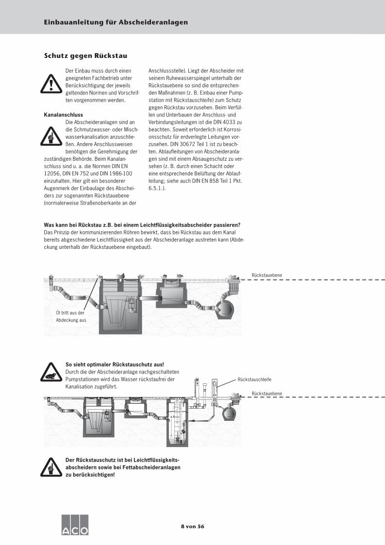
Was kann bei Rückstau z.B. bei einem Leichtflüssigkeitsabscheider passieren?Das Prinzip der kommunizierenden Röhren bewirkt, dass bei Rückstau aus dem Kanal bereits abgeschiedene Leichtflüssigkeit aus der Abscheideranlage austreten kann (Abde-ckung unterhalb der Rückstauebene eingebaut).
So sieht optimaler Rückstauschutz aus!Durch die der Abscheideranlage nachgeschalteten Pumpstationen wird das Wasser rückstaufrei der Kanalisation zugeführt.
Rückstauebene
Rückstauebene
Rückstauschleife
Öl tritt aus der
Abdeckung aus
Der Rückstauschutz ist bei Leichtflüssigkeits-abscheidern sowie bei Fettabscheideranlagen zu berücksichtigen!
9 von 56
Einbauanleitung für Abscheideranlagen
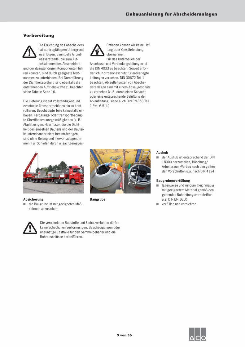
Aushub der Aushub ist entsprechend der DIN
18300 herzustellen, Böschung/Arbeitsraum/Verbau nach den gelten-den Vorschriften u.a. nach DIN 4124
Baugrubenverfüllung lagenweise und rundum gleichmäßig
mit geeignetem Material gemäß den geltenden Rohrleitungsvorschriften u.a. DIN EN 1610
verfüllen und verdichten
Vorbereitung
Die Errichtung des Abscheiders hat auf tragfähigem Untergrund zu erfolgen. Eventuelle Grund-wasserstände, die zum Auf-schwimmen des Abscheiders
und der dazugehörigen Komponenten füh-ren könnten, sind durch geeignete Maß-nahmen zu unterbinden. Bei Durchführung der Dichtheitsprüfung sind ebenfalls die entstehenden Auftriebskräfte zu beachten siehe Tabelle Seite 16.
Die Lieferung ist auf Vollständigkeit und eventuelle Transportschäden hin zu kont-rollieren. Beschädigte Teile keinesfalls ein-bauen. Fertigungs- oder transportbeding-te Oberflächenunregelmäßigkeiten (z. B. Abplatzungen, Haarrisse), die die Dicht-heit des einzelnen Bauteils und der Bautei-le untereinander nicht beeinträchtigen, sind ohne Belang und hiervon ausgenom-men. Für Schäden durch unsachgemäßes
Entladen können wir keine Haf-tung oder Gewährleistung übernehmen.Für das Unterbauen der
Anschluss- und Verbindungsleitungen ist die DIN 4033 zu beachten. Soweit erfor-derlich, Korrosionsschutz für erdverlegte Leitungen vorsehen. DIN 30672 Teil 1 beachten. Ablaufleitungen von Abschei-deranlagen sind mit einem Absaugeschutz zu versehen (z. B. durch einen Schacht oder eine entsprechende Belüftung der Ablaufleitung; siehe auch DIN EN 858 Teil 1 Pkt. 6.5.1.)
Absicherung die Baugrube ist mit geeigneten Maß-
nahmen abzusichern
Baugrube
Die verwendeten Baustoffe und Einbauverfahren dürfen keine schädlichen Verformungen, Beschädigungen oder ungünstige Lastfälle für den Sammelbehälter und die Rohranschlüsse herbeiführen.
10 von 56
Einbauanleitung für Abscheideranlagen
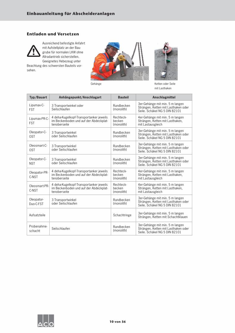
Entladen und Versetzen
Ausreichend befestigte Anfahrt mit Aufstellplatz an der Bau-grube für normalen LKW ohne Allradantrieb sicherstellen. Geeignetes Hebezeug unter
Beachtung des schwersten Bauteils vor-sehen.
Typ/Bauart Anhängepunkt/Anschlagart Bauteil Anschlagmittel
Lipumax-C-FST
3 Transportwinkel oder Seilschlaufen
Rundbecken (monolith)
3er-Gehänge mit min. 5 m langen Strängen, Ketten mit Lasthaken oder Seile. Schäkel NG 5 DIN 82101
Lipumax-PR-C-FST
4 deha-Kugelkopf-Transportanker jeweils im Beckenboden und auf der Abdeckplat-tenoberseite
Rechteck-becken (monolith)
4er-Gehänge mit min. 5 m langen Strängen, Ketten mit Lasthaken, mit Lastausgleich
Oleopator-C-OST
3 Transportwinkel oder Seilschlaufen
Rundbecken (monolith)
3er-Gehänge mit min. 5 m langen Strängen, Ketten mit Lasthaken oder Seile. Schäkel NG 5 DIN 82101
Oleosmart-C-OST
3 Transportwinkel oder Seilschlaufen
Rundbecken (monolith)
3er-Gehänge mit min. 5 m langen Strängen, Ketten mit Lasthaken oder Seile. Schäkel NG 5 DIN 82101
Oleopator-C-NST
3 Transportwinkel oder Seilschlaufen
Rundbecken (monolith)
3er-Gehänge mit min. 5 m langen Strängen, Ketten mit Lasthaken oder Seile. Schäkel NG 5 DIN 82101
Oleopator-PR-C-NST
4 deha-Kugelkopf-Transportanker jeweils im Beckenboden und auf der Abdeckplat-tenoberseite
Rechteck-becken (monolith)
4er-Gehänge mit min. 5 m langen Strängen, Ketten mit Lasthaken, mit Lastausgleich
Oleosmart-PR-C-NST
4 deha-Kugelkopf-Transportanker jeweils im Beckenboden und auf der Abdeckplat-tenoberseite
Rechteck-becken (monolith)
4er-Gehänge mit min. 5 m langen Strängen, Ketten mit Lasthaken,mit Lastausgleich
Oleopator-Duo-C-FST
3 Transportwinkel oder Seilschlaufen
Rundbecken (monolith)
3er-Gehänge mit min. 5 m langen Strängen, Ketten mit Lasthaken oder Seile. Schäkel NG 5 DIN 82101
Aufsatzteile Schachtringe 3er-Gehänge mit min. 5 m langen Strängen, Ketten mit Schachtklauen
Probenahme-schacht
Seilschlaufen Rundbecken (monolith)
3er-Gehänge mit min. 5 m langen Strängen, Ketten mit Lasthaken oder Seile. Schäkel NG 5 DIN 82101
Gehänge Ketten oder Seile
mit Lasthaken
11 von 56
Einbauanleitung für Abscheideranlagen
4a
3a1
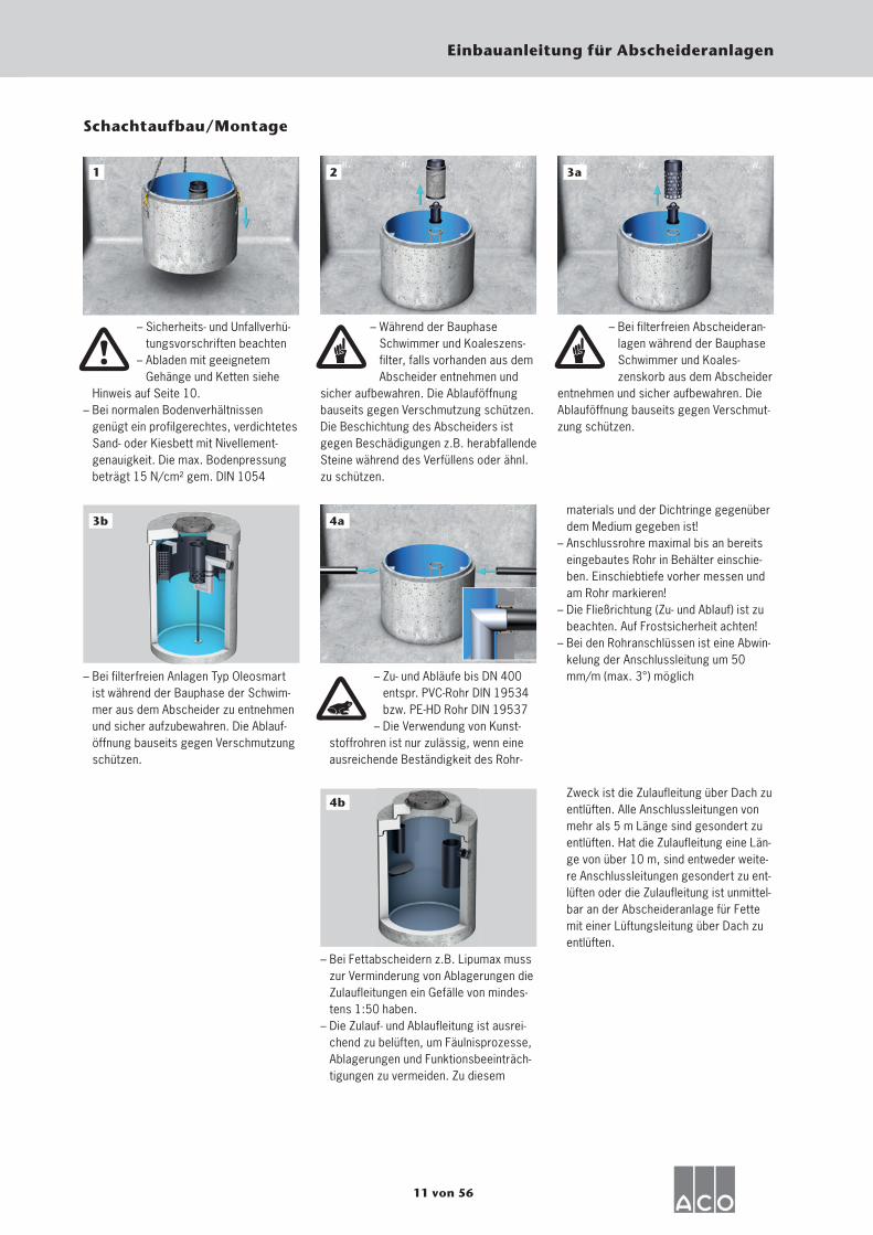
– Sicherheits- und Unfallverhü-tungsvorschriften beachten
– Abladen mit geeignetem Gehänge und Ketten siehe
Hinweis auf Seite 10.– Bei normalen Bodenverhältnissen
genügt ein profilgerechtes, verdichtetes Sand- oder Kiesbett mit Nivellement-genauigkeit. Die max. Bodenpressung beträgt 15 N/cm² gem. DIN 1054
2
– Während der Bauphase Schwimmer und Koaleszens-filter, falls vorhanden aus dem Abscheider entnehmen und
sicher aufbewahren. Die Ablauföffnung bauseits gegen Verschmutzung schützen. Die Beschichtung des Abscheiders ist gegen Beschädigungen z.B. herabfallende Steine während des Verfüllens oder ähnl. zu schützen.
– Bei filterfreien Abscheideran-lagen während der Bauphase Schwimmer und Koales-zenskorb aus dem Abscheider
entnehmen und sicher aufbewahren. Die Ablauföffnung bauseits gegen Verschmut-zung schützen.
– Zu- und Abläufe bis DN 400 entspr. PVC-Rohr DIN 19534 bzw. PE-HD Rohr DIN 19537
– Die Verwendung von Kunst- stoffrohren ist nur zulässig, wenn eine
ausreichende Beständigkeit des Rohr-
Schachtaufbau/Montage
– Bei filterfreien Anlagen Typ Oleosmart ist während der Bauphase der Schwim-mer aus dem Abscheider zu entnehmen und sicher aufzubewahren. Die Ablauf-öffnung bauseits gegen Verschmutzung schützen.
4b
– Bei Fettabscheidern z.B. Lipumax muss zur Verminderung von Ablagerungen die Zulaufleitungen ein Gefälle von mindes-tens 1:50 haben.
– Die Zulauf- und Ablaufleitung ist ausrei-chend zu belüften, um Fäulnisprozesse, Ablagerungen und Funktionsbeeinträch-tigungen zu vermeiden. Zu diesem
materials und der Dichtringe gegenüber dem Medium gegeben ist!
– Anschlussrohre maximal bis an bereits eingebautes Rohr in Behälter einschie-ben. Einschiebtiefe vorher messen und am Rohr markieren!
– Die Fließrichtung (Zu- und Ablauf) ist zu beachten. Auf Frostsicherheit achten!
– Bei den Rohranschlüssen ist eine Abwin-kelung der Anschlussleitung um 50 mm/m (max. 3°) möglich
Zweck ist die Zulaufleitung über Dach zu entlüften. Alle Anschlussleitungen von mehr als 5 m Länge sind gesondert zu entlüften. Hat die Zulaufleitung eine Län-ge von über 10 m, sind entweder weite-re Anschlussleitungen gesondert zu ent-lüften oder die Zulaufleitung ist unmittel-bar an der Abscheideranlage für Fette mit einer Lüftungsleitung über Dach zu entlüften.
3b
12 von 56
Einbauanleitung für Abscheideranlagen
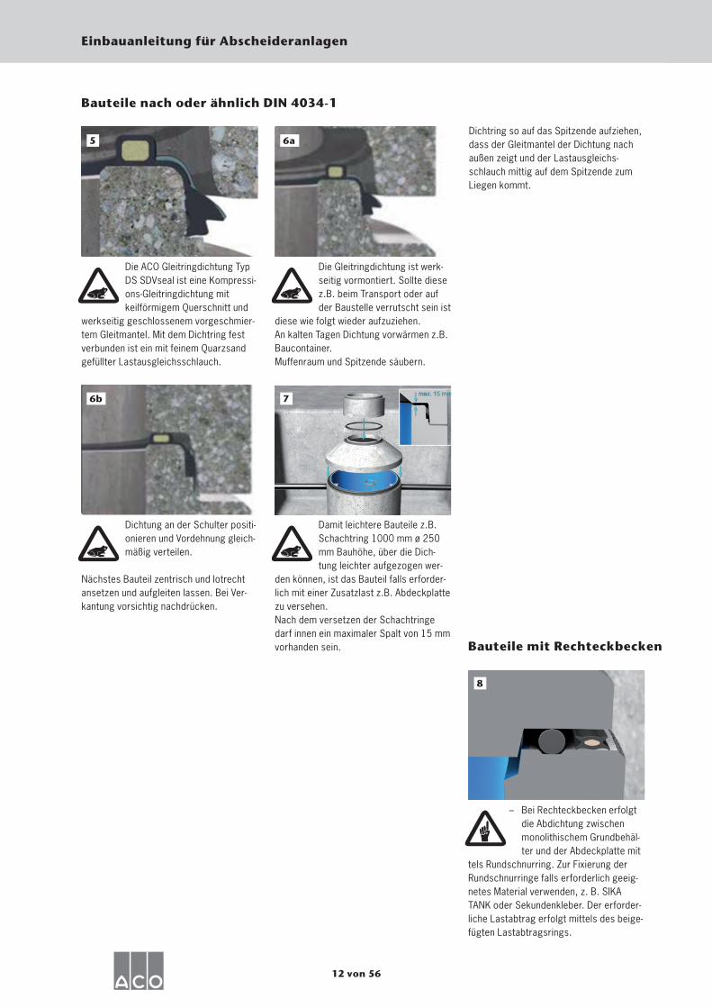
Bauteile nach oder ähnlich DIN 4034-1
Die ACO Gleitringdichtung Typ DS SDVseal ist eine Kompressi-ons-Gleitringdichtung mitkeilförmigem Querschnitt und
werkseitig geschlossenem vorgeschmier-tem Gleitmantel. Mit dem Dichtring fest verbunden ist ein mit feinem Quarzsand gefüllter Lastausgleichsschlauch.
Die Gleitringdichtung ist werk-seitig vormontiert. Sollte diese z.B. beim Transport oder auf der Baustelle verrutscht sein ist
diese wie folgt wieder aufzuziehen.An kalten Tagen Dichtung vorwärmen z.B. Baucontainer.Muffenraum und Spitzende säubern.
5Dichtring so auf das Spitzende aufziehen,dass der Gleitmantel der Dichtung nach außen zeigt und der Lastausgleichs-schlauch mittig auf dem Spitzende zum Liegen kommt.
Dichtung an der Schulter positi-onieren und Vordehnung gleich-mäßig verteilen.
Nächstes Bauteil zentrisch und lotrecht ansetzen und aufgleiten lassen. Bei Ver-kantung vorsichtig nachdrücken.
5
Damit leichtere Bauteile z.B. Schachtring 1000 mm ø 250 mm Bauhöhe, über die Dich-tung leichter aufgezogen wer-
den können, ist das Bauteil falls erforder-lich mit einer Zusatzlast z.B. Abdeckplatte zu versehen.Nach dem versetzen der Schachtringe darf innen ein maximaler Spalt von 15 mm vorhanden sein.
7
– Bei Rechteckbecken erfolgt die Abdichtung zwischen monolithischem Grundbehäl-ter und der Abdeckplatte mit
tels Rundschnurring. Zur Fixierung der Rundschnurringe falls erforderlich geeig-netes Material verwenden, z. B. SIKA TANK oder Sekundenkleber. Der erforder-liche Lastabtrag erfolgt mittels des beige-fügten Lastabtragsrings.
8
Bauteile mit Rechteckbecken
5 6a
6b
13 von 56
Einbauanleitung für Abscheideranlagen
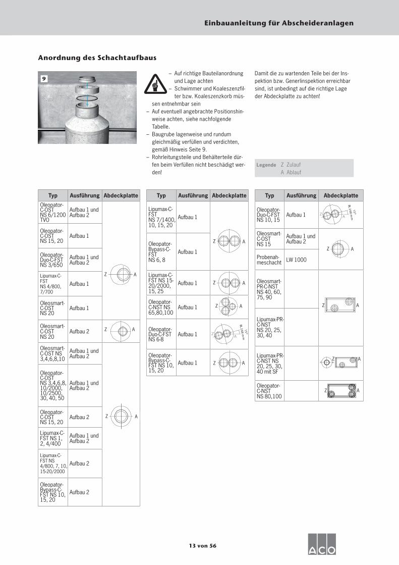
– Auf richtige Bauteilanordnung und Lage achten
– Schwimmer und Koaleszenzfil-ter bzw. Koaleszenzkorb müs-
sen entnehmbar sein– Auf eventuell angebrachte Positionshin-
weise achten, siehe nachfolgende Tabelle.
– Baugrube lagenweise und rundum gleichmäßig verfüllen und verdichten, gemäß Hinweis Seite 9.
– Rohrleitungsteile und Behälterteile dür-fen beim Verfüllen nicht beschädigt wer-den!
9
Anordnung des Schachtaufbaus
Legende
Damit die zu wartenden Teile bei der Ins-pektion bzw. Generlinspektion erreichbar sind, ist unbedingt auf die richtige Lage der Abdeckplatte zu achten!
Z ZulaufA Ablauf
Typ Ausführung Abdeckplatte
Oleopator-C-OSTNS 6/1200TVO
Aufbau 1 und Aufbau 2
Oleopator-C-OSTNS 15, 20
Aufbau 1
Oleopator-Duo-C-FST NS 3/650
Aufbau 1 und Aufbau 2
Lipumax-C-FSTNS 4/800, 7/700
Aufbau 1
Oleosmart-C-OSTNS 20
Aufbau 1
Oleosmart-C-OSTNS 20
Aufbau 2
Oleosmart-C-OST NS 3,4,6,8,10
Aufbau 1 und Aufbau 2
Oleopator-C-OST NS 3,4,6,8, 10/2000, 10/2500, 30, 40, 50
Aufbau 1 und Aufbau 2
Oleopator-C-OSTNS 15, 20
Aufbau 2
Lipumax-C-FST NS 1, 2, 4/400
Aufbau 1 und Aufbau 2
Lipumax-C-FST NS 4/800, 7, 10,15-20/2000
Aufbau 2
Oleopator-Bypass-C-FST NS 10, 15, 20
Aufbau 2
Z A
A
Z A
Z A
Z A
Lipumax-C-FSTNS 7/1400, 10, 15, 20
Aufbau 1
Oleopator-Bypass-C-FSTNS 6, 8
Aufbau 1
Lipumax-C-FST NS 15- 20/2000, 15, 25
Aufbau 1
Oleopator-C-NST NS 65,80,100
Aufbau 1
Oleopator-Duo-C-FST NS 6-8
Aufbau 1
Oleopator-Bypass-C-FST NS 10, 15, 20
Aufbau 1
Typ Ausführung Abdeckplatte Typ Ausführung Abdeckplatte
Oleopator-Duo-C-FST NS 10, 15
Aufbau 1
Oleosmart-C-OSTNS 15
Aufbau 1 und Aufbau 2
Probenah-meschacht LW 1000
Oleosmart-PR-C-NST NS 40, 60, 75, 90
Lipumax-PR-C-NSTNS 20, 25, 30, 40
Lipumax-PR-C-NST NS 20, 25, 30, 40 mit SF
Oleopator-C-NSTNS 80,100
Z A
15
BL 26
8 m
m
15
BL 26
8 m
m
Z A
Z A
AZ
Z A
Z A
Z
14 von 56
Einbauanleitung für Abscheideranlagen
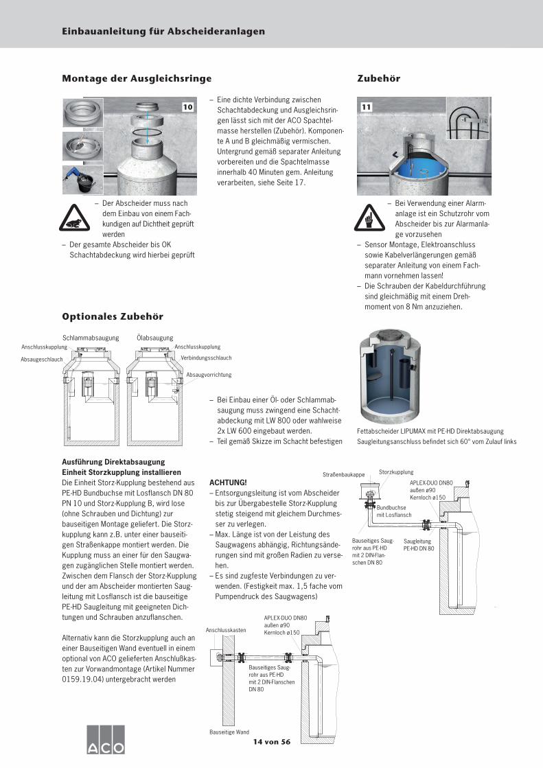
– Der Abscheider muss nach dem Einbau von einem Fach-kundigen auf Dichtheit geprüft werden
– Der gesamte Abscheider bis OK Schachtabdeckung wird hierbei geprüft
10
Montage der Ausgleichsringe
– Eine dichte Verbindung zwischen Schachtabdeckung und Ausgleichsrin-gen lässt sich mit der ACO Spachtel-masse herstellen (Zubehör). Komponen-te A und B gleichmäßig vermischen. Untergrund gemäß separater Anleitung vorbereiten und die Spachtelmasse innerhalb 40 Minuten gem. Anleitung verarbeiten, siehe Seite 17.
– Bei Verwendung einer Alarm-anlage ist ein Schutzrohr vom Abscheider bis zur Alarmanla-ge vorzusehen
– Sensor Montage, Elektroanschluss sowie Kabelverlängerungen gemäß separater Anleitung von einem Fach-mann vornehmen lassen!
– Die Schrauben der Kabeldurchführung sind gleichmäßig mit einem Dreh-moment von 8 Nm anzuziehen.
11
Zubehör
Optionales Zubehör
– Bei Einbau einer Öl- oder Schlammab-saugung muss zwingend eine Schacht-abdeckung mit LW 800 oder wahlweise 2x LW 600 eingebaut werden.
– Teil gemäß Skizze im Schacht befestigen
Ausführung DirektabsaugungEinheit Storzkupplung installierenDie Einheit Storz-Kupplung bestehend aus PE-HD Bundbuchse mit Losflansch DN 80 PN 10 und Storz-Kupplung B, wird lose (ohne Schrauben und Dichtung) zur bauseitigen Montage geliefert. Die Storz-kupplung kann z.B. unter einer bauseiti-gen Straßenkappe montiert werden. Die Kupplung muss an einer für den Saugwa-gen zugänglichen Stelle montiert werden. Zwischen dem Flansch der Storz-Kupplung und der am Abscheider montierten Saug-leitung mit Losflansch ist die bauseitige PE-HD Saugleitung mit geeigneten Dich-tungen und Schrauben anzuflanschen.
Alternativ kann die Storzkupplung auch an einer Bauseitigen Wand eventuell in einem optional von ACO gelieferten Anschlußkas-ten zur Vorwandmontage (Artikel Nummer 0159.19.04) untergebracht werden
ACHTUNG!– Entsorgungsleitung ist vom Abscheider
bis zur Übergabestelle Storz-Kupplung stetig steigend mit gleichem Durchmes-ser zu verlegen.
– Max. Länge ist von der Leistung des Saugwagens abhängig, Richtungsände-rungen sind mit großen Radien zu verse-hen.
– Es sind zugfeste Verbindungen zu ver-wenden. (Festigkeit max. 1,5 fache vom Pumpendruck des Saugwagens)
Schlammabsaugung Ölabsaugung Anschlusskupplung
Absaugeschlauch
Anschlusskupplung
Absaugvorrichtung
Verbindungsschlauch
Fettabscheider LIPUMAX mit PE-HD Direktabsaugung
Saugleitungsanschluss befindet sich 60° vom Zulauf links
Bundbuchse mit Losflansch
APLEX-DUO DN80außen ø90Kernloch ø150
Straßenbaukappe Storzkupplung
Saugleitung PE-HD DN 80
Bauseitiges Saug-rohr aus PE-HD mit 2 DIN-Flan-schen DN 80
Bauseitige Wand
Anschlusskasten
APLEX-DUO DN80außen ø90Kernloch ø150
Bauseitiges Saug-rohr aus PE-HDmit 2 DIN-Flanschen DN 80
15 von 56
Einbauanleitung für Abscheideranlagen
Probenahmeschacht
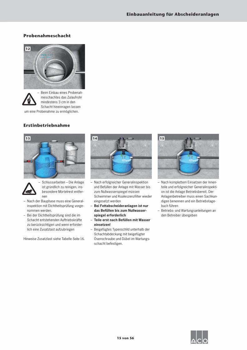
– Beim Einbau eines Probenah-meschachtes das Zulaufrohr mindestens 3 cm in den Schacht hineinragen lassen
um eine Probenahme zu ermöglichen.
12
– Schlussarbeiten – Die Anlage ist gründlich zu reinigen, ins-besondere Mörtelrest entfer-nen
– Nach der Bauphase muss eine General-inspektion mit Dichtheitsprüfung vorge-nommen werden.
– Bei der Dichtheitsprüfung sind die im Schacht entstehenden Auftriebskräfte zu berücksichtigen und wenn erforder-lich eine Zusatzlast aufzubringen
Hinweise Zusatzlast siehe Tabelle Seite 16.
13
Erstinbetriebnahme
– Nach erfolgreicher Generalinspektion und Befüllen der Anlage mit Wasser bis zum Nullwasserspiegel müssen Schwimmer und Koaleszenzfilter wieder eingesetzt werden
– Bei Fettabscheideranlagen ist nur das Befüllen bis zum Nullwasser-spiegel erforderlich
– Teile erst nach Befüllen mit Wasser einsetzen!
– Beigefügtes Typenschild unterhalb der Schachtabdeckung mit beigefügter Ösenschraube und Dübel im Wartungs-schacht befestigen.
14
– Nach komplettem Einsetzen der Innen-teile und erfolgreicher Generalinspekti-on ist die Anlage Betriebsbereit. Der Anlagenbetreiber muss einen Sachkun-digen benennen und ein Betriebstage-buch führen
– Betriebs- und Wartungsanleitungen an den Betreiber übergeben
15
16 von 56
Einbauanleitung für Abscheideranlagen
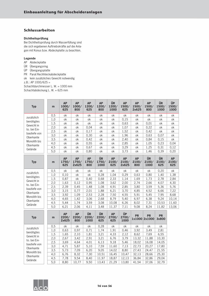
Schlussarbeiten
DichtheitsprüfungBei Dichtheitsprüfung durch Wasserfüllung sind die sich ergebenen Auftriebskräfte auf die Anla-gen mit Konus bzw. Abdeckplatte zu beachten.
LegendeAP AbdeckplatteÜR ÜbergangsringÜP ÜbergangsplattePR Parat Rechhteckabdeckplatteok kein zusätzliches Gewicht notwendigz.B.: AP 1000/625 = Schachtdurchmesser L. W. = 1000 mmSchachtabdeckung L. W. = 625 mm
Typ mAP
1000/625
AP1000/800
AP1200/625
AP1200/800
ÜR1200/1000
AP1500/625
AP1500/2x625
AP1500/800
ÜR1500/1000
ÜP1500/1000
zusätzlich benötigtes Gewicht in to. bei Ein-bautiefe von Oberkante Monolith bis Oberkante Gelände
0,5 ok ok ok ok ok ok ok ok ok ok1,0 ok ok ok ok ok 0,15 ok ok ok ok1,5 ok ok ok ok ok 0,63 ok 0,01 ok ok2,0 ok ok 0,04 ok ok 1,07 ok 0,22 ok ok2,5 ok ok 0,17 ok ok 1,52 ok 0,42 ok ok3,0 ok ok 0,30 ok ok 1,96 ok 0,63 0,07 ok3,5 ok ok 0,42 ok ok 2,40 ok 0,84 0,15 ok4,0 ok ok 0,55 ok ok 2,85 ok 1,05 0,23 0,044,5 ok ok 0,67 ok ok 3,29 ok 1,25 0,31 0,125,0 ok ok 0,80 ok ok 3,73 ok 1,46 0,39 0,20
Typ mAP
1750/625
AP1750/2x625
AP1750/800
ÜR1750/1000
AP2100/625
AP2100/2x625
AP2100/800
ÜR2100/1000
ÜR2100/625
AP2100/625
zusätzlich benötigtes Gewicht in to. bei Ein-bautiefe von Oberkante Monolith bis Oberkante Gelände
0,5 ok ok ok ok ok ok ok ok 0,20 ok1,0 0,10 ok ok 0,28 1,04 0,29 0,63 0,80 1,40 1,381,5 0,87 ok 0,40 0,68 2,33 1,14 1,69 1,73 2,78 2,842,0 1,63 0,12 0,95 1,08 3,62 2,00 2,74 2,66 4,07 4,302,5 2,39 0,45 1,48 1,08 4,91 2,85 3,80 3,59 5,36 5,763,0 3,15 0,77 2,01 1,88 6,21 3,70 4,85 4,52 6,66 7,223,5 3,92 1,09 2,53 2,28 7,50 4,55 5,91 5,45 7,95 8,684,0 4,65 1,42 3,06 2,68 8,79 5,40 6,97 6,38 9,24 10,144,5 5,44 1,74 3,59 3,08 10,08 6,26 8,02 7,31 10,53 11,605,0 6,21 2,06 4,11 3,48 11,37 7,11 9,08 8,24 11,82 13,06
Typ mAP
2200/2x625
AP2200/800
ÜR2200/1000
ÜR2200/625
AP2700/625
ÜP2700/1000
PR1x1000
PR2x1000
PR3x800
zusätzlich benötigtes Gewicht in to. bei Ein-bautiefe von Oberkante Monolith bis Oberkante Gelände
0,5 ok ok ok 0,28 ok ok ok ok ok1,0 0,63 0,97 0,71 1,74 1,91 0,46 3,92 3,49 2,811,5 1,65 2,10 1,81 3,21 4,33 2,12 8,62 7,69 6,552,0 2,67 3,42 2,91 3,21 6,76 3,79 13,32 11,88 10,302,5 3,69 4,64 4,01 6,13 9,18 5,46 18,02 16,08 14,053,0 4,71 5,87 5,10 7,59 11,60 7,13 22,73 20,27 17,803,5 5,73 7,09 6,20 9,05 14,02 8,80 27,43 24,47 21,554,0 6,76 8,32 7,30 10,51 16,45 10,47 32,13 28,66 25,304,5 7,78 9,54 8,40 11,97 18,87 12,13 36,84 32,86 29,045,0 8,80 10,77 9,50 13,43 21,29 13,80 41,54 37,06 32,79

17 von 56
Einbauanleitung für Abscheideranlagen
Montage mit Spachtelmasse
Schachtausgleichsringe und die Schacht-abdeckung können mit einer 2-Komponen-ten Spachtelmasse wasserdicht versetzt werden.
– Umlaufende Fläche am Ausgleichsring aufrauen und anschließend trocken rei-nigen
– Komponente B (Härter) zu Komponente A (Spachtelmasse) geben (Bedienungs-anleitung an Komponente A abgedruckt)
– Intensiv mit einer Rührmaschine gleich-mäßig vermischen
– Gesamte Spachtelmasse auf umlaufen-der Fläche gleichmäßig verteilen
– Verarbeitungszeit ca. 40 Minuten
– Nächsten Ausgleichsring oder Schacht-abdeckung aufsetzen
– Herausquellende Masse glätten– Werkzeuge sofort mit z.B. Aceton reini-
gen (ausgehärtete Reste können nur noch mechanisch entfernt werden)
18 von 56
Einbauanleitung für Abscheideranlagen
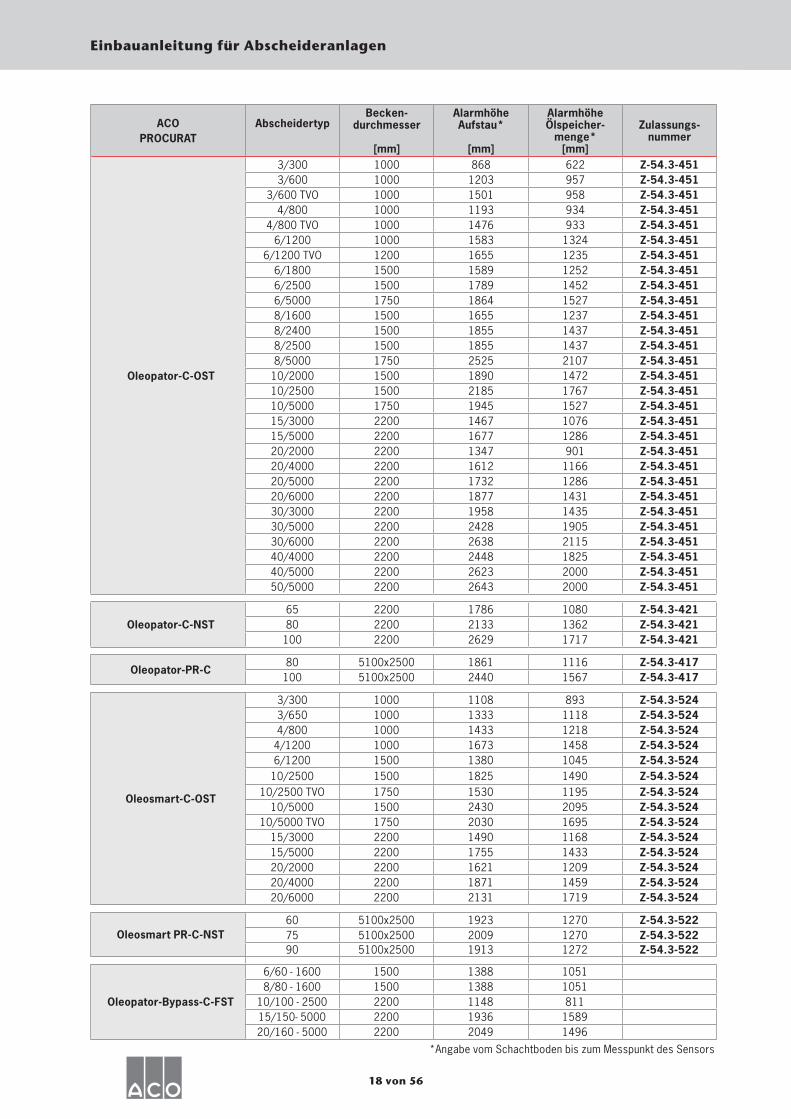
ACO PROCURAT
AbscheidertypBecken-
durchmesser
[mm]
Alarmhöhe Aufstau*
[mm]
Alarmhöhe Ölspeicher-
menge*[mm]
Zulassungs- nummer
Oleopator-C-OST
3/300 1000 868 622 Z-54.3-4513/600 1000 1203 957 Z-54.3-451
3/600 TVO 1000 1501 958 Z-54.3-4514/800 1000 1193 934 Z-54.3-451
4/800 TVO 1000 1476 933 Z-54.3-4516/1200 1000 1583 1324 Z-54.3-451
6/1200 TVO 1200 1655 1235 Z-54.3-4516/1800 1500 1589 1252 Z-54.3-4516/2500 1500 1789 1452 Z-54.3-4516/5000 1750 1864 1527 Z-54.3-4518/1600 1500 1655 1237 Z-54.3-4518/2400 1500 1855 1437 Z-54.3-4518/2500 1500 1855 1437 Z-54.3-4518/5000 1750 2525 2107 Z-54.3-451
10/2000 1500 1890 1472 Z-54.3-45110/2500 1500 2185 1767 Z-54.3-45110/5000 1750 1945 1527 Z-54.3-45115/3000 2200 1467 1076 Z-54.3-45115/5000 2200 1677 1286 Z-54.3-45120/2000 2200 1347 901 Z-54.3-45120/4000 2200 1612 1166 Z-54.3-45120/5000 2200 1732 1286 Z-54.3-45120/6000 2200 1877 1431 Z-54.3-45130/3000 2200 1958 1435 Z-54.3-45130/5000 2200 2428 1905 Z-54.3-45130/6000 2200 2638 2115 Z-54.3-45140/4000 2200 2448 1825 Z-54.3-45140/5000 2200 2623 2000 Z-54.3-45150/5000 2200 2643 2000 Z-54.3-451
Oleopator-C-NST65 2200 1786 1080 Z-54.3-42180 2200 2133 1362 Z-54.3-421
100 2200 2629 1717 Z-54.3-421
Oleopator-PR-C80 5100x2500 1861 1116 Z-54.3-417
100 5100x2500 2440 1567 Z-54.3-417
Oleosmart-C-OST
3/300 1000 1108 893 Z-54.3-5243/650 1000 1333 1118 Z-54.3-5244/800 1000 1433 1218 Z-54.3-524
4/1200 1000 1673 1458 Z-54.3-5246/1200 1500 1380 1045 Z-54.3-524
10/2500 1500 1825 1490 Z-54.3-52410/2500 TVO 1750 1530 1195 Z-54.3-524
10/5000 1500 2430 2095 Z-54.3-52410/5000 TVO 1750 2030 1695 Z-54.3-524
15/3000 2200 1490 1168 Z-54.3-52415/5000 2200 1755 1433 Z-54.3-52420/2000 2200 1621 1209 Z-54.3-52420/4000 2200 1871 1459 Z-54.3-52420/6000 2200 2131 1719 Z-54.3-524
Oleosmart PR-C-NST60 5100x2500 1923 1270 Z-54.3-52275 5100x2500 2009 1270 Z-54.3-52290 5100x2500 1913 1272 Z-54.3-522
Oleopator-Bypass-C-FST
6/60 - 1600 1500 1388 10518/80 - 1600 1500 1388 1051
10/100 - 2500 2200 1148 81115/150- 5000 2200 1936 158920/160 - 5000 2200 2049 1496
*Angabe vom Schachtboden bis zum Messpunkt des Sensors

19 von 56
Einbauanleitung für Abscheideranlagen
’H’-A
ufst
au
’H’-Ö
l
Länge x Breite
’H’-A
ufst
au
’H’-Ö
lBeckendurchmesser
’H’-A
ufst
au
’H’-Ö
l
Beckendurchmesser
Oleopator-C-OST
Oleosmart-C-OST
Oleopator-C-NST
Oleopator-PR-C
Oleosmart-PR-C-NST
Oleopator-Bypasss-C-FST
20 of 56
Installation instructions for separator systems
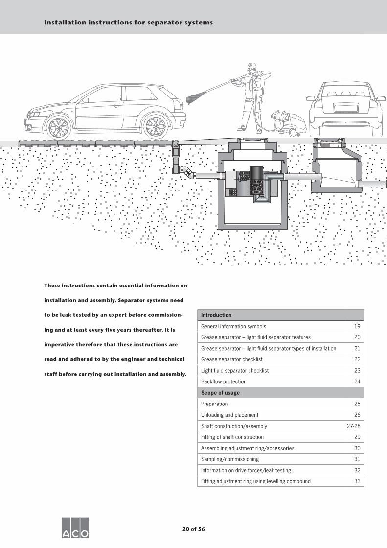
These instructions contain essential information on
installation and assembly. Separator systems need
to be leak tested by an expert before commission-
ing and at least every five years thereafter. It is
imperative therefore that these instructions are
read and adhered to by the engineer and technical
staff before carrying out installation and assembly.
Introduction
General information symbols 19
Grease separator – light fluid separator features 20
Grease separator – light fluid separator types of installation 21
Grease separator checklist 22
Light fluid separator checklist 23
Backflow protection 24
Scope of usage
Preparation 25
Unloading and placement 26
Shaft construction/assembly 27-28
Fitting of shaft construction 29
Assembling adjustment ring/accessories 30
Sampling/commissioning 31
Information on drive forces/leak testing 32
Fitting adjustment ring using levelling compound 33
21 of 56
Installation instructions for separator systems
General information
symbols
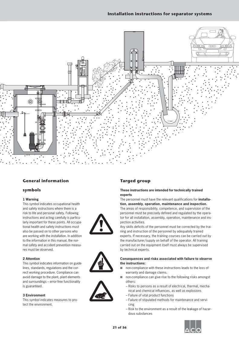
1 WarningThis symbol indicates occupational health and safety instructions where there is a risk to life and personal safety. Following instructions and acting carefully is particu-larly important for these points. All occupa-tional health and safety instructions must also be passed on to other persons who are working with the installation. In addition to the information in this manual, the nor-mal safety and accident prevention measu-res must be observed.
2 Attention This symbol indicates information on guide-lines, standards, regulations and the cor-rect working procedure. Compliance can avoid damage to the plant, plant elements and surroundings – error-free functionality is guaranteed.
3 Environment This symbol indicates measures to pro-tect the environment.
Targed group
These instructions are intended for technically trained expertsThe personnel must have the relevant qualifications for installa-tion, assembly, operation, maintenance and inspection.The areas of responsibility, competence, and supervision of the personnel must be precisely defined and regulated by the opera-tor for all installation, assembly, operation, maintenance and ins-pection activities.Any skills deficits of the personnel must be corrected by the trai-ning and instruction of the personnel by adequately trained experts. If necessary, the training courses can be carried out by the manufacturer/supply on behalf of the operator. All training carried out on the equipment itself must always be supervised by technical experts. Consequences and risks associated with failure to observe the instructions:▪ non-compliance with these instructions leads to the loss of
warranty and damage claims.▪ non-compliance can give rise to the following risks amongst
others: – Risks to persons as a result of electrical, thermal, mecha-
nical and chemical influences, as well as explosions – Failure of vital product functions – Failure of stipulated methods for maintenance and servi-
cing – Risk to the environment as a result of the leakage of hazar-
dous substances
22 of 56
Installation instructions for separator systems
Grease separator – light fluid separator features
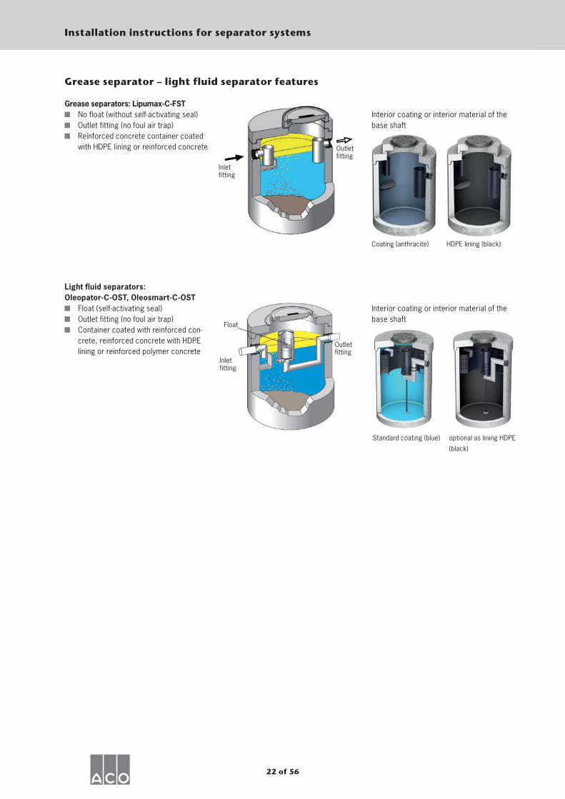
Grease separators: Lipumax-C-FST No float (without self-activating seal) Outlet fitting (no foul air trap) Reinforced concrete container coated
with HDPE lining or reinforced concrete
Light fluid separators: Oleopator-C-OST, Oleosmart-C-OST
Float (self-activating seal) Outlet fitting (no foul air trap) Container coated with reinforced con-
crete, reinforced concrete with HDPE lining or reinforced polymer concrete
Interior coating or interior material of the base shaft
Coating (anthracite) HDPE lining (black)
Interior coating or interior material of the base shaft
Standard coating (blue) optional as lining HDPE
(black)
Inlet fitting
Outlet fitting
Outlet fitting
Float
Inlet fitting
23 of 56
Installation instructions for separator systems
Types of installation – grease separators
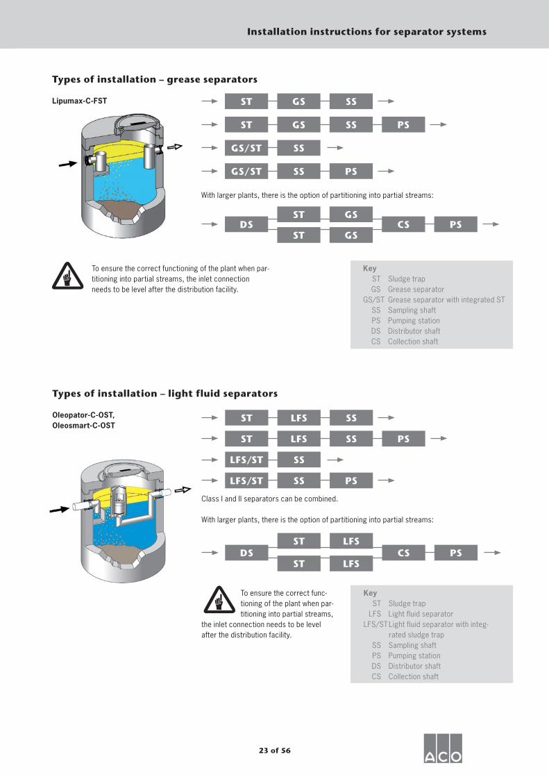
Lipumax-C-FST
PS
ST GS SS
ST GS SS
GS/ST SS
GS/ST SS PS
With larger plants, there is the option of partitioning into partial streams:
DSST GS
ST GSCS PS
To ensure the correct functioning of the plant when par-titioning into partial streams, the inlet connection needs to be level after the distribution facility.
Key ST Sludge trap GS Grease separator GS/ST Grease separator with integrated ST SS Sampling shaft PS Pumping station DS Distributor shaft CS Collection shaft
Oleopator-C-OST, Oleosmart-C-OST
PS
Types of installation – light fluid separators
ST LFS SS
ST LFS SS
LFS/ST SS
LFS/ST SS PS
Class I and II separators can be combined.
With larger plants, there is the option of partitioning into partial streams:
DSST LFS
ST LFSCS PS
To ensure the correct func-tioning of the plant when par-titioning into partial streams,
the inlet connection needs to be level after the distribution facility.
Key ST Sludge trap LFS Light fluid separator LFS/ST Light fluid separator with integ-
rated sludge trap SS Sampling shaft PS Pumping station DS Distributor shaft CS Collection shaft
24 of 56
Installation instructions for separator systems
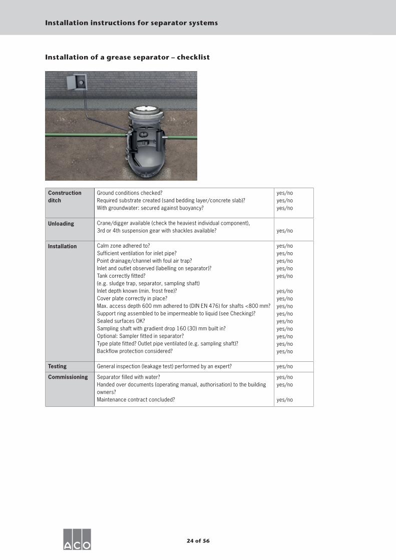
Construction ditch
Ground conditions checked? Required substrate created (sand bedding layer/concrete slab)? With groundwater: secured against buoyancy?
yes/no yes/no yes/no
Unloading Crane/digger available (check the heaviest individual component), 3rd or 4th suspension gear with shackles available? yes/no
Installation Calm zone adhered to? Sufficient ventilation for inlet pipe? Point drainage/channel with foul air trap? Inlet and outlet observed (labelling on separator)? Tank correctly fitted? (e.g. sludge trap, separator, sampling shaft) Inlet depth known (min. frost free)? Cover plate correctly in place? Max. access depth 600 mm adhered to (DIN EN 476) for shafts <800 mm? Support ring assembled to be impermeable to liquid (see Checking)? Sealed surfaces OK? Sampling shaft with gradient drop 160 (30) mm built in? Optional: Sampler fitted in separator? Type plate fitted? Outlet pipe ventilated (e.g. sampling shaft)? Backflow protection considered?
yes/no yes/no yes/no yes/no yes/no
yes/no yes/no yes/no yes/no yes/no yes/no yes/no yes/no yes/no
Testing General inspection (leakage test) performed by an expert? yes/no
Commissioning Separator filled with water? Handed over documents (operating manual, authorisation) to the building owners? Maintenance contract concluded?
yes/no yes/no
yes/no
Installation of a grease separator – checklist
25 von 56
Einbauanleitung für Abscheideranlagen
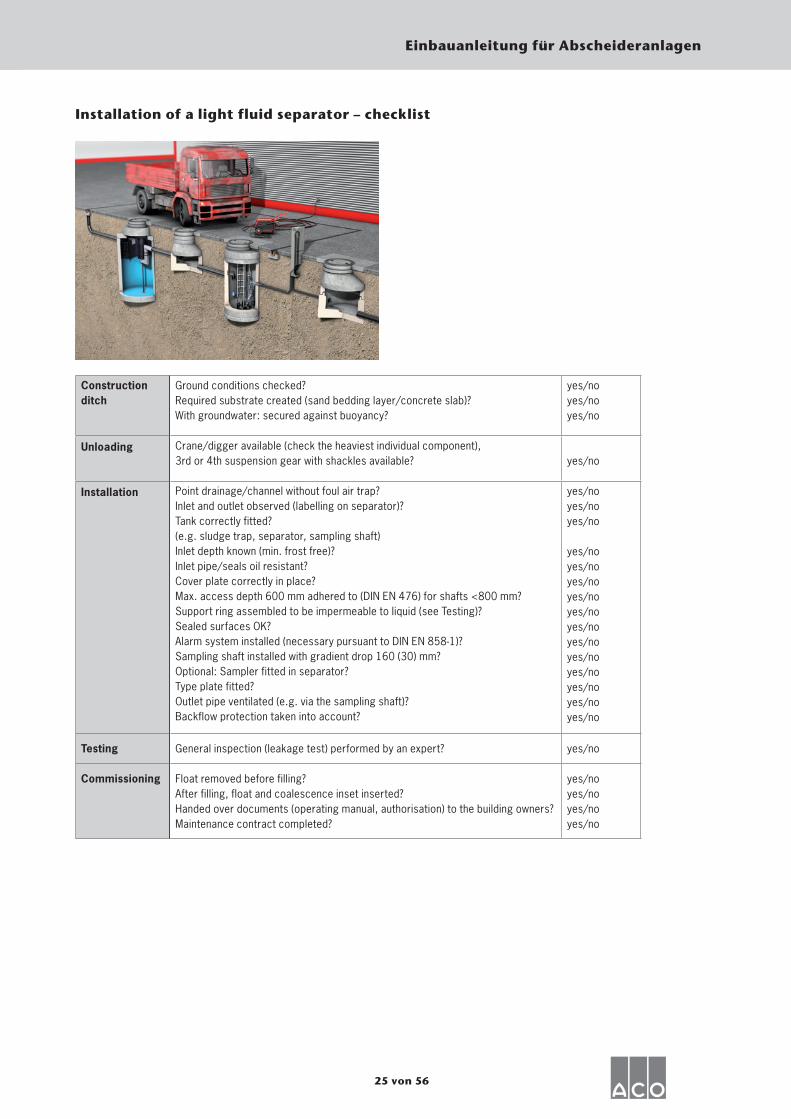
Construction ditch
Ground conditions checked? Required substrate created (sand bedding layer/concrete slab)? With groundwater: secured against buoyancy?
yes/no yes/no yes/no
Unloading Crane/digger available (check the heaviest individual component),3rd or 4th suspension gear with shackles available? yes/no
Installation Point drainage/channel without foul air trap? Inlet and outlet observed (labelling on separator)? Tank correctly fitted? (e.g. sludge trap, separator, sampling shaft) Inlet depth known (min. frost free)? Inlet pipe/seals oil resistant? Cover plate correctly in place? Max. access depth 600 mm adhered to (DIN EN 476) for shafts <800 mm? Support ring assembled to be impermeable to liquid (see Testing)? Sealed surfaces OK? Alarm system installed (necessary pursuant to DIN EN 858-1)? Sampling shaft installed with gradient drop 160 (30) mm? Optional: Sampler fitted in separator? Type plate fitted? Outlet pipe ventilated (e.g. via the sampling shaft)? Backflow protection taken into account?
yes/no yes/no yes/no
yes/no yes/no yes/no yes/no yes/no yes/no yes/no yes/no yes/no yes/no yes/no yes/no
Testing General inspection (leakage test) performed by an expert? yes/no
Commissioning Float removed before filling? After filling, float and coalescence inset inserted? Handed over documents (operating manual, authorisation) to the building owners? Maintenance contract completed?
yes/no yes/no yes/no yes/no
Installation of a light fluid separator – checklist
26 of 56
Installation instructions for separator systems
Backflow protection
Installation must be carried out by a specialist company taking into account the applicable stan-dards and regulations.
Duct connection The separator systems need to be connected to the waste water or combined waste water sewer system. Other types of connec-tions require approval from the
relevant authorities. For a duct connec-tion, the standards that need to be com-plied with include DIN EN 12056, DIN EN 752 and DIN 1986-100. Particular atten-tion should be paid here to the installation position of the separator in relation to the
so-called backflow level (normally the upper surface of the street at the connec-tion point). If the at-rest water level of the separator is below the backflow level, then corresponding measures to protect against backflow need to be taken (e.g. installation of a pumping station with backflow loop). When back-filling and crea-ting the foundations for the connecting pipes, DIN 4033 must be observed. If necessary, underground piping needs to be protected against corrosion. DIN 30672 Part 1 must be complied with. Separator system outlet pipes require suction protection (e.g. via a shaft or by ventilating the outlet pipe; see also DIN EN 858, part 1, point 6.5.1).
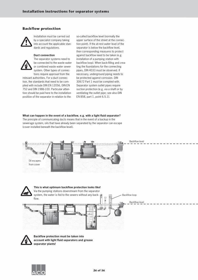
What can happen in the event of a backflow, e.g. with a light fluid separator?The principle of communicating ducts means that in the event of a backup in the sewerage system, oils that have already been separated by the separator can escape (cover installed beneath the backflow level).
This is what optimum backflow protection looks like! Via the pumping stations downstream from the separator system, the water is fed to the sewers without any back-flow.
Backflow level
Backflow level
Backflow loop
Oil escapes
from cover
Backflow protection must be taken into account with light fluid separators and grease separator plants!
27 of 56
Installation instructions for separator systems
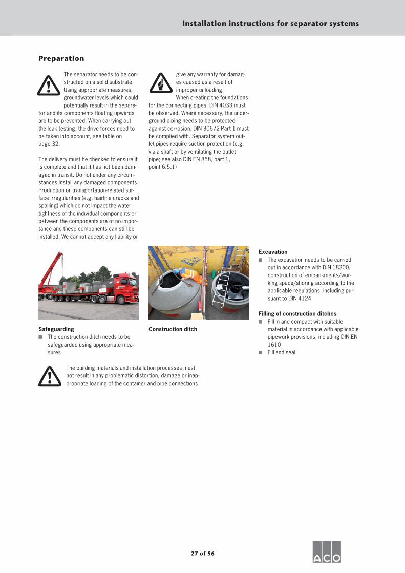
Excavation The excavation needs to be carried
out in accordance with DIN 18300, construction of embankments/wor-king space/shoring according to the applicable regulations, including pur-suant to DIN 4124
Filling of construction ditches Fill in and compact with suitable
material in accordance with applicable pipework provisions, including DIN EN 1610
Fill and seal
Preparation
The separator needs to be con-structed on a solid substrate. Using appropriate measures, groundwater levels which could potentially result in the separa-
tor and its components floating upwards are to be prevented. When carrying out the leak testing, the drive forces need to be taken into account, see table on page 32.
The delivery must be checked to ensure it is complete and that it has not been dam-aged in transit. Do not under any circum-stances install any damaged components. Production or transportation-related sur-face irregularities (e.g. hairline cracks and spalling) which do not impact the water-tightness of the individual components or between the components are of no impor-tance and these components can still be installed. We cannot accept any liability or
give any warranty for damag-es caused as a result of improper unloading. When creating the foundations
for the connecting pipes, DIN 4033 must be observed. Where necessary, the under-ground piping needs to be protected against corrosion. DIN 30672 Part 1 must be complied with. Separator system out-let pipes require suction protection (e.g. via a shaft or by ventilating the outlet pipe; see also DIN EN 858, part 1, point 6.5.1)
Safeguarding The construction ditch needs to be
safeguarded using appropriate mea-sures
Construction ditch
The building materials and installation processes must not result in any problematic distortion, damage or inap-propriate loading of the container and pipe connections.
28 of 56
Installation instructions for separator systems
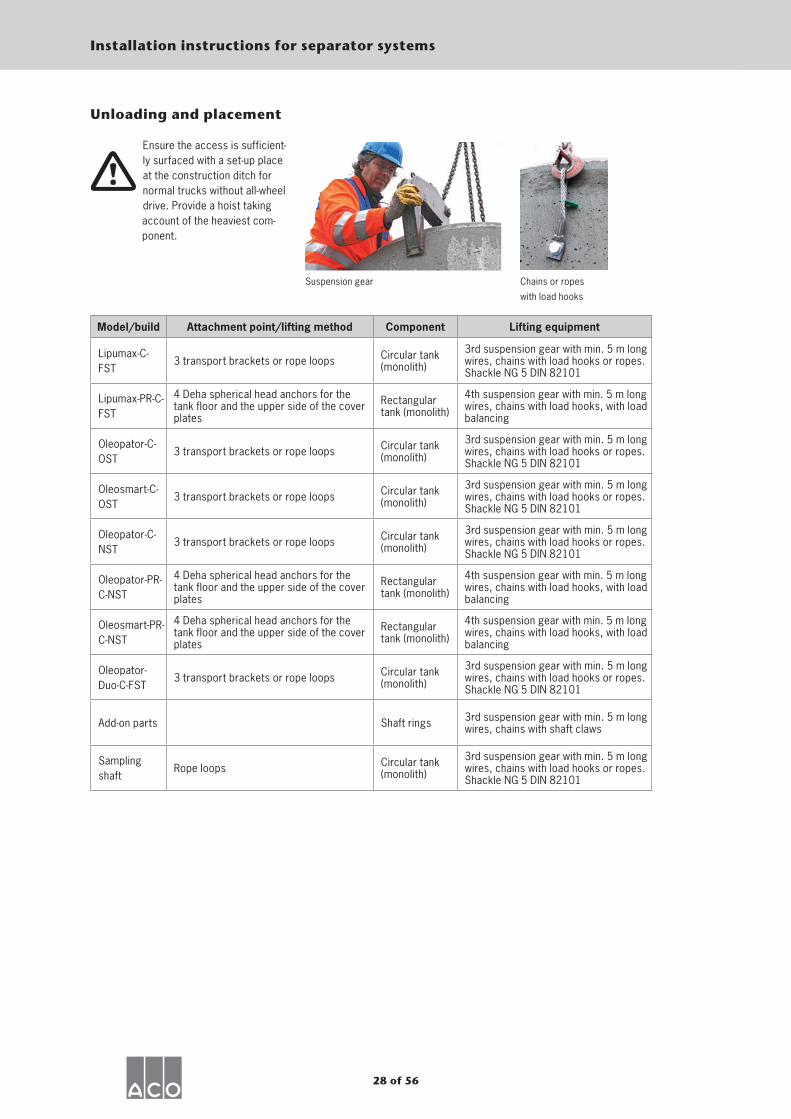
Unloading and placement
Ensure the access is sufficient-ly surfaced with a set-up place at the construction ditch for normal trucks without all-wheel drive. Provide a hoist taking
account of the heaviest com-ponent.
Model/build Attachment point/lifting method Component Lifting equipment
Lipumax-C-FST
3 transport brackets or rope loops Circular tank (monolith)
3rd suspension gear with min. 5 m long wires, chains with load hooks or ropes. Shackle NG 5 DIN 82101
Lipumax-PR-C-FST
4 Deha spherical head anchors for the tank floor and the upper side of the cover plates
Rectangular tank (monolith)
4th suspension gear with min. 5 m long wires, chains with load hooks, with load balancing
Oleopator-C-OST
3 transport brackets or rope loops Circular tank (monolith)
3rd suspension gear with min. 5 m long wires, chains with load hooks or ropes. Shackle NG 5 DIN 82101
Oleosmart-C-OST
3 transport brackets or rope loops Circular tank (monolith)
3rd suspension gear with min. 5 m long wires, chains with load hooks or ropes. Shackle NG 5 DIN 82101
Oleopator-C-NST
3 transport brackets or rope loops Circular tank (monolith)
3rd suspension gear with min. 5 m long wires, chains with load hooks or ropes. Shackle NG 5 DIN 82101
Oleopator-PR-C-NST
4 Deha spherical head anchors for the tank floor and the upper side of the cover plates
Rectangular tank (monolith)
4th suspension gear with min. 5 m long wires, chains with load hooks, with load balancing
Oleosmart-PR-C-NST
4 Deha spherical head anchors for the tank floor and the upper side of the cover plates
Rectangular tank (monolith)
4th suspension gear with min. 5 m long wires, chains with load hooks, with load balancing
Oleopator-Duo-C-FST
3 transport brackets or rope loops Circular tank (monolith)
3rd suspension gear with min. 5 m long wires, chains with load hooks or ropes. Shackle NG 5 DIN 82101
Add-on parts Shaft rings 3rd suspension gear with min. 5 m long wires, chains with shaft claws
Sampling shaft
Rope loops Circular tank (monolith)
3rd suspension gear with min. 5 m long wires, chains with load hooks or ropes. Shackle NG 5 DIN 82101
Suspension gear Chains or ropes
with load hooks
29 of 56
Installation instructions for separator systems
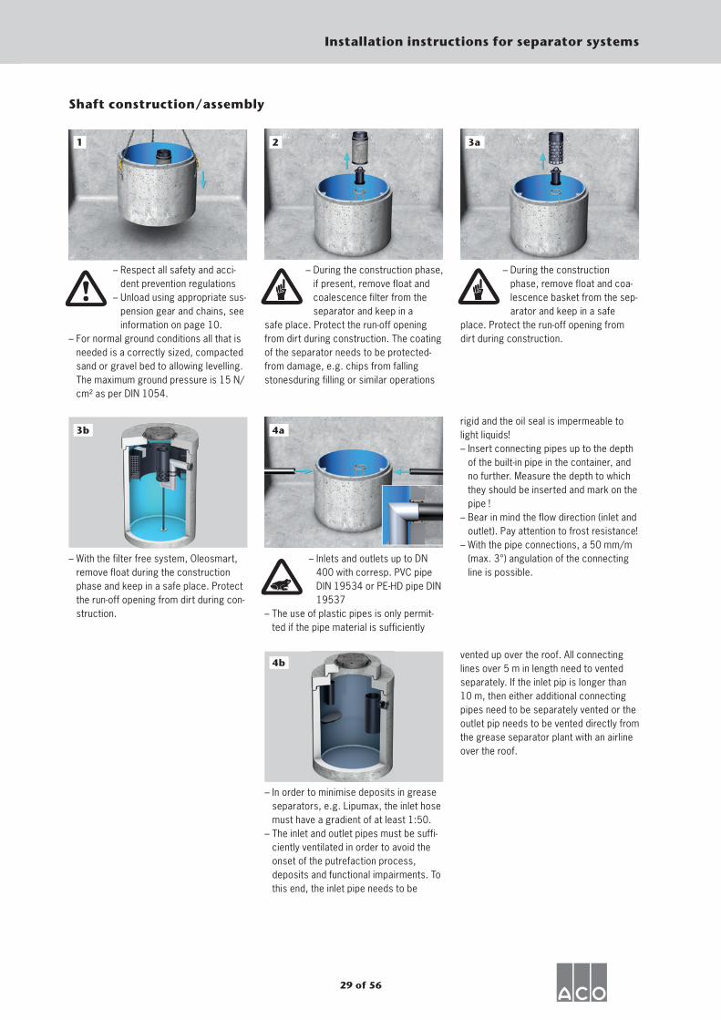
1
– Respect all safety and acci-dent prevention regulations
– Unload using appropriate sus-pension gear and chains, see information on page 10.
– For normal ground conditions all that is needed is a correctly sized, compacted sand or gravel bed to allowing levelling. The maximum ground pressure is 15 N/cm² as per DIN 1054.
2
– During the construction phase, if present, remove float and coalescence filter from the separator and keep in a
safe place. Protect the run-off openingfrom dirt during construction. The coatingof the separator needs to be protected-from damage, e.g. chips from falling stonesduring filling or similar operations
– During the construction phase, remove float and coa-lescence basket from the sep-arator and keep in a safe
place. Protect the run-off opening from dirt during construction.
– Inlets and outlets up to DN 400 with corresp. PVC pipe DIN 19534 or PE-HD pipe DIN 19537
– The use of plastic pipes is only permit-ted if the pipe material is sufficiently
Shaft construction/assembly
– With the filter free system, Oleosmart, remove float during the construction phase and keep in a safe place. Protect the run-off opening from dirt during con-struction.
– In order to minimise deposits in grease separators, e.g. Lipumax, the inlet hose must have a gradient of at least 1:50.
– The inlet and outlet pipes must be suffi-ciently ventilated in order to avoid the onset of the putrefaction process, deposits and functional impairments. To this end, the inlet pipe needs to be
rigid and the oil seal is impermeable to light liquids!– Insert connecting pipes up to the depth
of the built-in pipe in the container, and no further. Measure the depth to which they should be inserted and mark on the pipe !
– Bear in mind the flow direction (inlet and outlet). Pay attention to frost resistance!
– With the pipe connections, a 50 mm/m (max. 3°) angulation of the connecting line is possible.
vented up over the roof. All connecting lines over 5 m in length need to vented separately. If the inlet pip is longer than 10 m, then either additional connecting pipes need to be separately vented or the outlet pip needs to be vented directly from the grease separator plant with an airline over the roof.
4a
3a
4b
3b
30 of 56
Installation instructions for separator systems
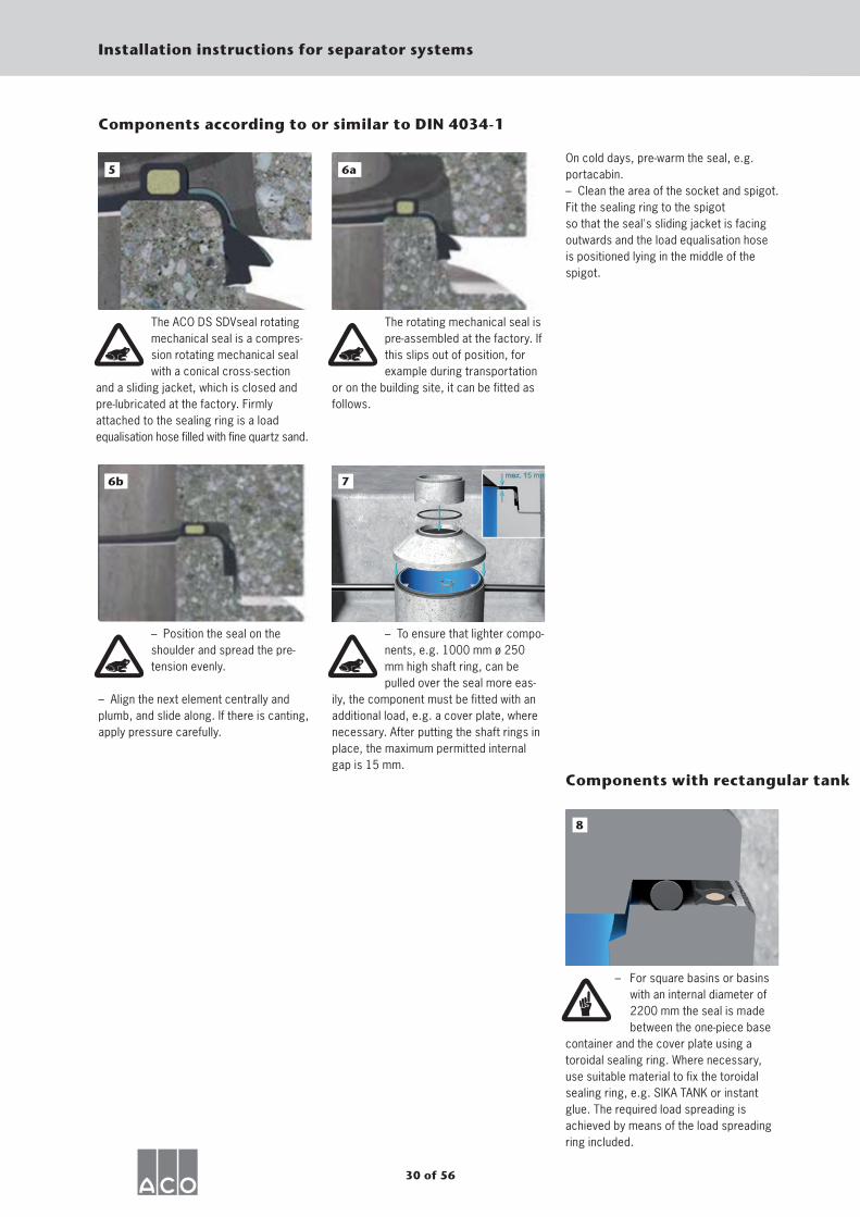
Components according to or similar to DIN 4034-1
The ACO DS SDVseal rotating mechanical seal is a compres-sion rotating mechanical seal with a conical cross-section
and a sliding jacket, which is closed and pre-lubricated at the factory. Firmly attached to the sealing ring is a load equalisation hose filled with fine quartz sand.
5
The rotating mechanical seal is pre-assembled at the factory. If this slips out of position, for example during transportation
or on the building site, it can be fitted as follows.
56aOn cold days, pre-warm the seal, e.g. portacabin.– Clean the area of the socket and spigot.Fit the sealing ring to the spigotso that the seal's sliding jacket is facing outwards and the load equalisation hose is positioned lying in the middle of the spigot.
– Position the seal on the shoulder and spread the pre-tension evenly.
– Align the next element centrally and plumb, and slide along. If there is canting, apply pressure carefully.
56b
– To ensure that lighter compo-nents, e.g. 1000 mm ø 250 mm high shaft ring, can be pulled over the seal more eas-
ily, the component must be fitted with an additional load, e.g. a cover plate, where necessary. After putting the shaft rings in place, the maximum permitted internal gap is 15 mm.
7
– For square basins or basins with an internal diameter of 2200 mm the seal is made between the one-piece base
container and the cover plate using a toroidal sealing ring. Where necessary, use suitable material to fix the toroidal sealing ring, e.g. SIKA TANK or instant glue. The required load spreading is achieved by means of the load spreading ring included.
8
Components with rectangular tank
31 of 56
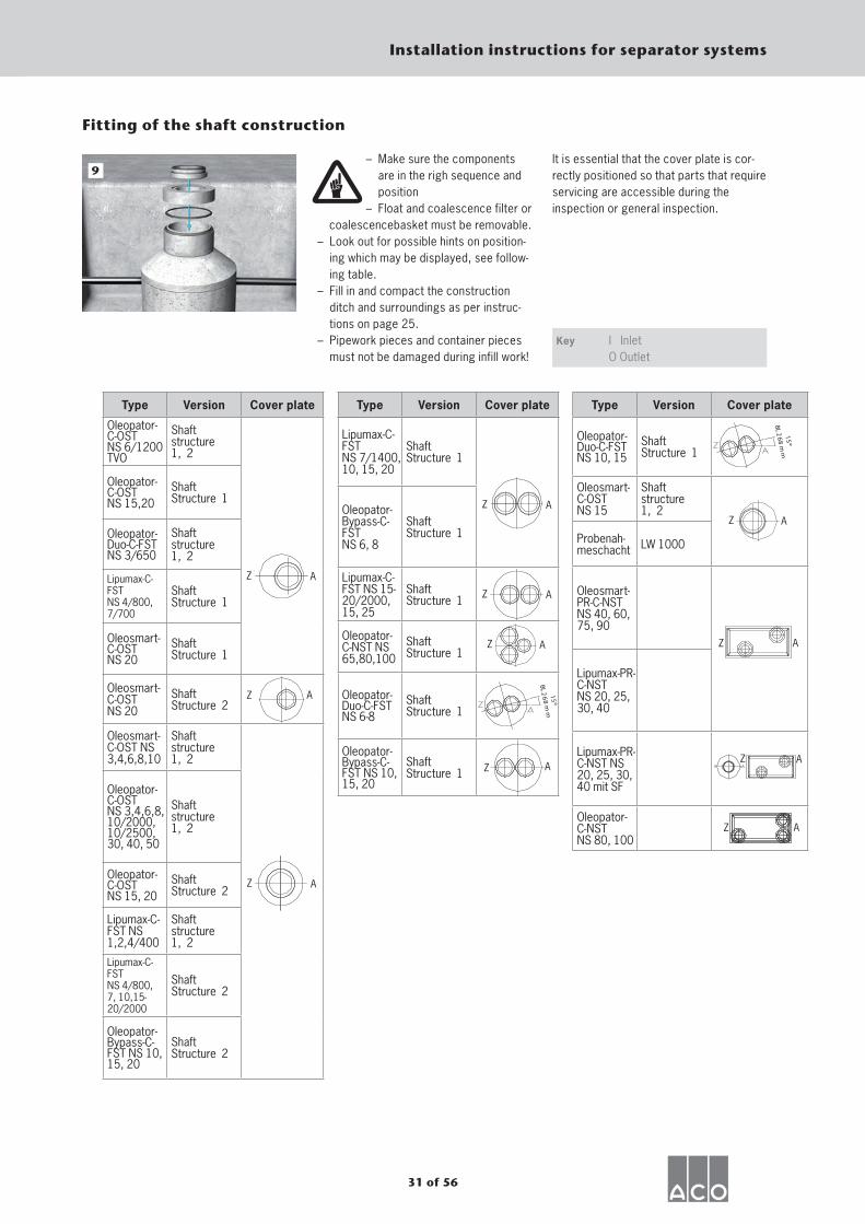
Installation instructions for separator systems
– Make sure the components are in the righ sequence and position
– Float and coalescence filter or coalescencebasket must be removable.– Look out for possible hints on position-
ing which may be displayed, see follow-ing table.
– Fill in and compact the construction ditch and surroundings as per instruc-tions on page 25.
– Pipework pieces and container pieces must not be damaged during infill work!
9
Fitting of the shaft construction
Key
It is essential that the cover plate is cor-rectly positioned so that parts that require servicing are accessible during the inspection or general inspection.
I InletO Outlet
Type Version Cover plate
Oleopator-C-OSTNS 6/1200TVO
Shaftstructure 1, 2
Oleopator-C-OSTNS 15,20
Shaft Structure 1
Oleopator-Duo-C-FST NS 3/650
Shaftstructure 1, 2
Lipumax-C-FSTNS 4/800, 7/700
Shaft Structure 1
Oleosmart-C-OSTNS 20
Shaft Structure 1
Oleosmart-C-OST NS 20
Shaft Structure 2
Oleosmart-C-OST NS 3,4,6,8,10
Shaftstructure 1, 2
Oleopator-C-OST NS 3,4,6,8, 10/2000, 10/2500, 30, 40, 50
Shaftstructure 1, 2
Oleopator-C-OSTNS 15, 20
Shaft Structure 2
Lipumax-C-FST NS 1,2,4/400
Shaftstructure 1, 2
Lipumax-C-FSTNS 4/800,7, 10,15-20/2000
Shaft Structure 2
Oleopator-Bypass-C-FST NS 10, 15, 20
Shaft Structure 2
Z A
A
Z A
Z A
Z A
Lipumax-C-FSTNS 7/1400, 10, 15, 20
Shaft Structure 1
Oleopator-Bypass-C-FSTNS 6, 8
Shaft Structure 1
Lipumax-C-FST NS 15- 20/2000, 15, 25
Shaft Structure 1
Oleopator-C-NST NS 65,80,100
Shaft Structure 1
Oleopator-Duo-C-FST NS 6-8
Shaft Structure 1
Oleopator-Bypass-C-FST NS 10, 15, 20
Shaft Structure 1
Type Version Cover plate Type Version Cover plate
Oleopator-Duo-C-FST NS 10, 15
Shaft Structure 1
Oleosmart-C-OSTNS 15
Shaftstructure 1, 2
Probenah-meschacht LW 1000
Oleosmart-PR-C-NST NS 40, 60, 75, 90
Lipumax-PR-C-NSTNS 20, 25, 30, 40
Lipumax-PR-C-NST NS 20, 25, 30, 40 mit SF
Oleopator-C-NSTNS 80, 100
Z A
15
BL 26
8 m
m
15
BL 26
8 m
m
Z A
Z A
AZ
Z A
Z A
Z
32 of 56
Installation instructions for separator systems
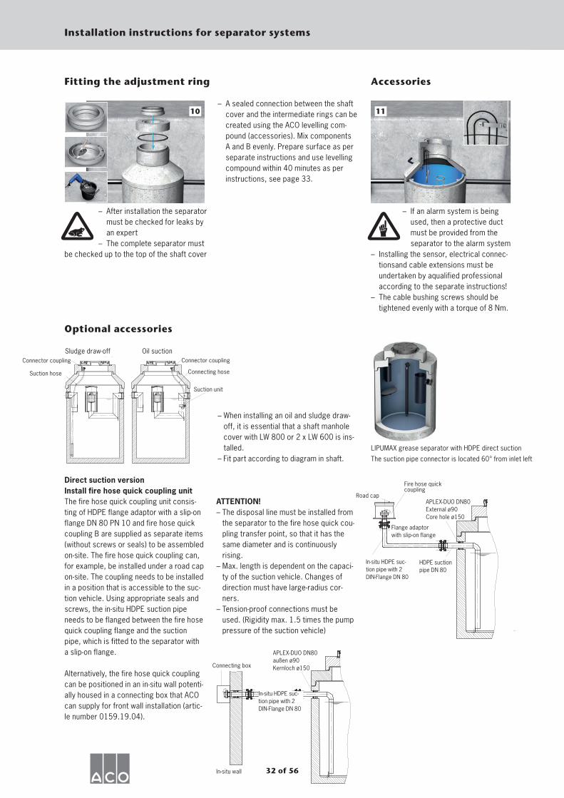
– After installation the separator must be checked for leaks by an expert
– The complete separator mustbe checked up to the top of the shaft cover
10
Fitting the adjustment ring
– A sealed connection between the shaft cover and the intermediate rings can be created using the ACO levelling com-pound (accessories). Mix components A and B evenly. Prepare surface as per separate instructions and use levelling compound within 40 minutes as per instructions, see page 33.
– If an alarm system is being used, then a protective duct must be provided from the separator to the alarm system
– Installing the sensor, electrical connec-tionsand cable extensions must be undertaken by aqualified professional according to the separate instructions!
– The cable bushing screws should be tightened evenly with a torque of 8 Nm.
11
Accessories
Optional accessories
– When installing an oil and sludge draw-off, it is essential that a shaft manhole cover with LW 800 or 2 x LW 600 is ins-talled.
– Fit part according to diagram in shaft.
Direct suction version Install fire hose quick coupling unit The fire hose quick coupling unit consis-ting of HDPE flange adaptor with a slip-on flange DN 80 PN 10 and fire hose quick coupling B are supplied as separate items (without screws or seals) to be assembled on-site. The fire hose quick coupling can, for example, be installed under a road cap on-site. The coupling needs to be installed in a position that is accessible to the suc-tion vehicle. Using appropriate seals and screws, the in-situ HDPE suction pipe needs to be flanged between the fire hose quick coupling flange and the suction pipe, which is fitted to the separator with a slip-on flange.
Alternatively, the fire hose quick coupling can be positioned in an in-situ wall potenti-ally housed in a connecting box that ACO can supply for front wall installation (artic-le number 0159.19.04).
ATTENTION!– The disposal line must be installed from
the separator to the fire hose quick cou-pling transfer point, so that it has the same diameter and is continuously rising.
– Max. length is dependent on the capaci-ty of the suction vehicle. Changes of direction must have large-radius cor-ners.
– Tension-proof connections must be used. (Rigidity max. 1.5 times the pump pressure of the suction vehicle)
Sludge draw-off Oil suction Connector coupling
Suction hose
Connector coupling
Suction unit
Connecting hose
LIPUMAX grease separator with HDPE direct suction
The suction pipe connector is located 60° from inlet left
Flange adaptor with slip-on flange
APLEX-DUO DN80 External ø90 Core hole ø150
Road cap
Fire hose quick coupling
HDPE suction pipe DN 80
In-situ HDPE suc-tion pipe with 2 DIN-Flange DN 80
In-situ wall
Connecting box
APLEX-DUO DN80außen ø90Kernloch ø150
In-situ HDPE suc-tion pipe with 2 DIN-Flange DN 80
33 of 56
Installation instructions for separator systems
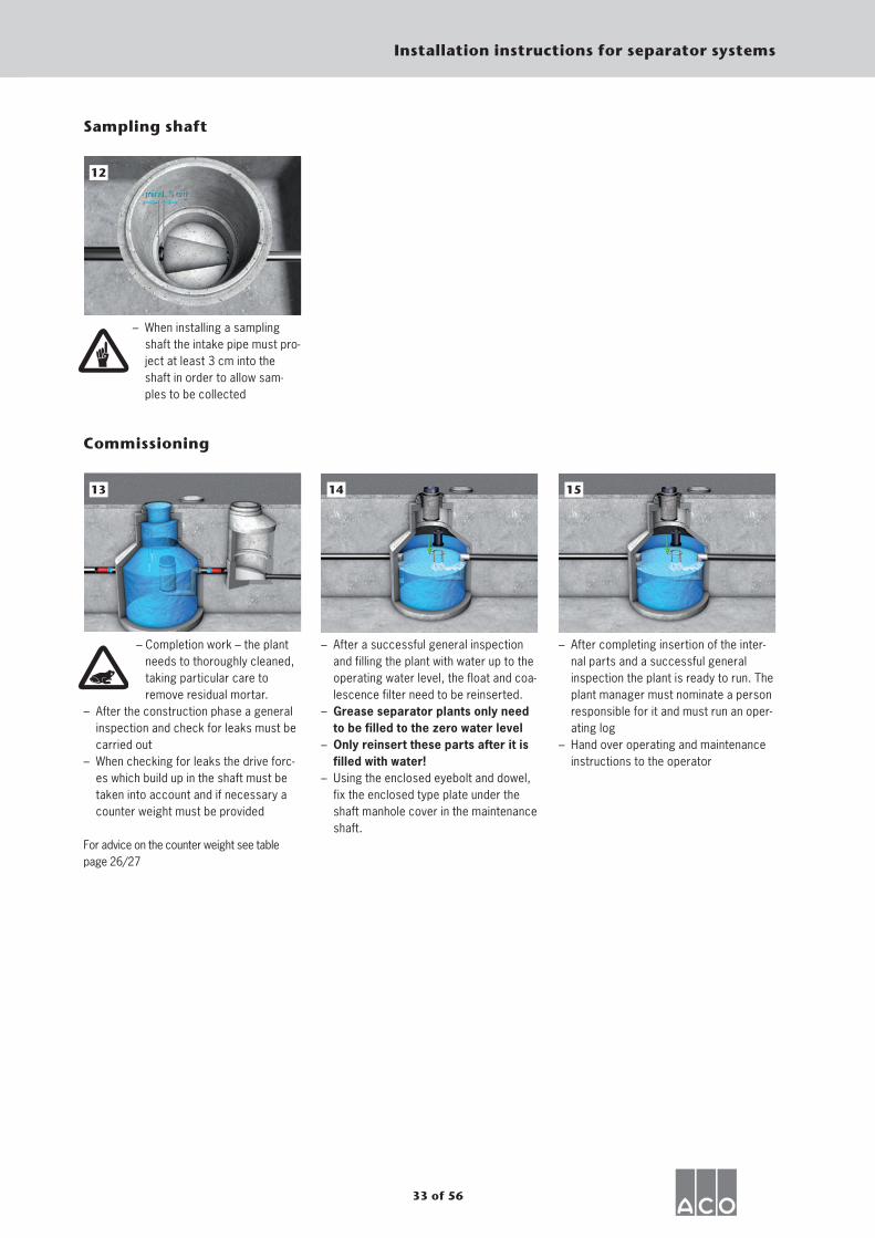
Sampling shaft
– When installing a sampling shaft the intake pipe must pro-ject at least 3 cm into the shaft in order to allow sam-ples to be collected
12
– Completion work – the plant needs to thoroughly cleaned, taking particular care to remove residual mortar.
– After the construction phase a general inspection and check for leaks must be carried out
– When checking for leaks the drive forc-es which build up in the shaft must be taken into account and if necessary a counter weight must be provided
For advice on the counter weight see tablepage 26/27
13
Commissioning
– After a successful general inspection and filling the plant with water up to the operating water level, the float and coa-lescence filter need to be reinserted.
– Grease separator plants only need to be filled to the zero water level
– Only reinsert these parts after it is filled with water!
– Using the enclosed eyebolt and dowel, fix the enclosed type plate under the shaft manhole cover in the maintenance shaft.
14
– After completing insertion of the inter-nal parts and a successful general inspection the plant is ready to run. The plant manager must nominate a person responsible for it and must run an oper-ating log
– Hand over operating and maintenance instructions to the operator
15
34 of 56
Installation instructions for separator systems
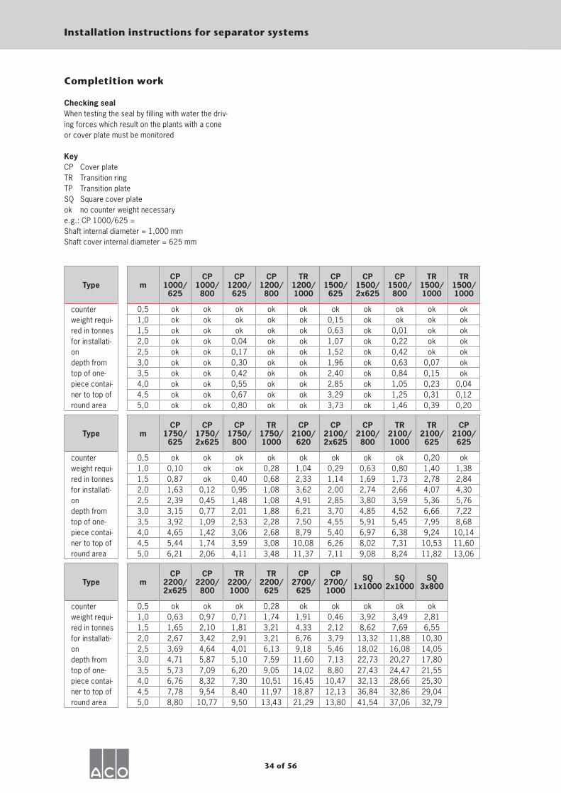
Completition work
Checking sealWhen testing the seal by filling with water the driv-ing forces which result on the plants with a coneor cover plate must be monitored
KeyCP Cover plateTR Transition ringTP Transition plateSQ Square cover plateok no counter weight necessarye.g.: CP 1000/625 =Shaft internal diameter = 1,000 mmShaft cover internal diameter = 625 mm
Type mCP
1000/625
CP1000/800
CP1200/625
CP1200/800
TR1200/1000
CP1500/625
CP1500/2x625
CP1500/800
TR1500/1000
TR1500/1000
counterweight requi-red in tonnesfor installati-on depth from top of one-piece contai-ner to top ofround area
0,5 ok ok ok ok ok ok ok ok ok ok1,0 ok ok ok ok ok 0,15 ok ok ok ok1,5 ok ok ok ok ok 0,63 ok 0,01 ok ok2,0 ok ok 0,04 ok ok 1,07 ok 0,22 ok ok2,5 ok ok 0,17 ok ok 1,52 ok 0,42 ok ok3,0 ok ok 0,30 ok ok 1,96 ok 0,63 0,07 ok3,5 ok ok 0,42 ok ok 2,40 ok 0,84 0,15 ok4,0 ok ok 0,55 ok ok 2,85 ok 1,05 0,23 0,044,5 ok ok 0,67 ok ok 3,29 ok 1,25 0,31 0,125,0 ok ok 0,80 ok ok 3,73 ok 1,46 0,39 0,20
Type mCP
1750/625
CP1750/2x625
CP1750/800
TR1750/1000
CP2100/620
CP2100/2x625
CP2100/800
TR2100/1000
TR2100/625
CP2100/625
counterweight requi-red in tonnesfor installati-ondepth fromtop of one-piece contai-ner to top ofround area
0,5 ok ok ok ok ok ok ok ok 0,20 ok1,0 0,10 ok ok 0,28 1,04 0,29 0,63 0,80 1,40 1,381,5 0,87 ok 0,40 0,68 2,33 1,14 1,69 1,73 2,78 2,842,0 1,63 0,12 0,95 1,08 3,62 2,00 2,74 2,66 4,07 4,302,5 2,39 0,45 1,48 1,08 4,91 2,85 3,80 3,59 5,36 5,763,0 3,15 0,77 2,01 1,88 6,21 3,70 4,85 4,52 6,66 7,223,5 3,92 1,09 2,53 2,28 7,50 4,55 5,91 5,45 7,95 8,684,0 4,65 1,42 3,06 2,68 8,79 5,40 6,97 6,38 9,24 10,144,5 5,44 1,74 3,59 3,08 10,08 6,26 8,02 7,31 10,53 11,605,0 6,21 2,06 4,11 3,48 11,37 7,11 9,08 8,24 11,82 13,06
Type mCP
2200/2x625
CP2200/800
TR2200/1000
TR2200/625
CP2700/625
CP2700/1000
SQ1x1000
SQ2x1000
SQ3x800
counterweight requi-red in tonnesfor installati-ondepth fromtop of one-piece contai-ner to top ofround area
0,5 ok ok ok 0,28 ok ok ok ok ok1,0 0,63 0,97 0,71 1,74 1,91 0,46 3,92 3,49 2,811,5 1,65 2,10 1,81 3,21 4,33 2,12 8,62 7,69 6,552,0 2,67 3,42 2,91 3,21 6,76 3,79 13,32 11,88 10,302,5 3,69 4,64 4,01 6,13 9,18 5,46 18,02 16,08 14,053,0 4,71 5,87 5,10 7,59 11,60 7,13 22,73 20,27 17,803,5 5,73 7,09 6,20 9,05 14,02 8,80 27,43 24,47 21,554,0 6,76 8,32 7,30 10,51 16,45 10,47 32,13 28,66 25,304,5 7,78 9,54 8,40 11,97 18,87 12,13 36,84 32,86 29,045,0 8,80 10,77 9,50 13,43 21,29 13,80 41,54 37,06 32,79
35 of 56
Installation instructions for separator systems
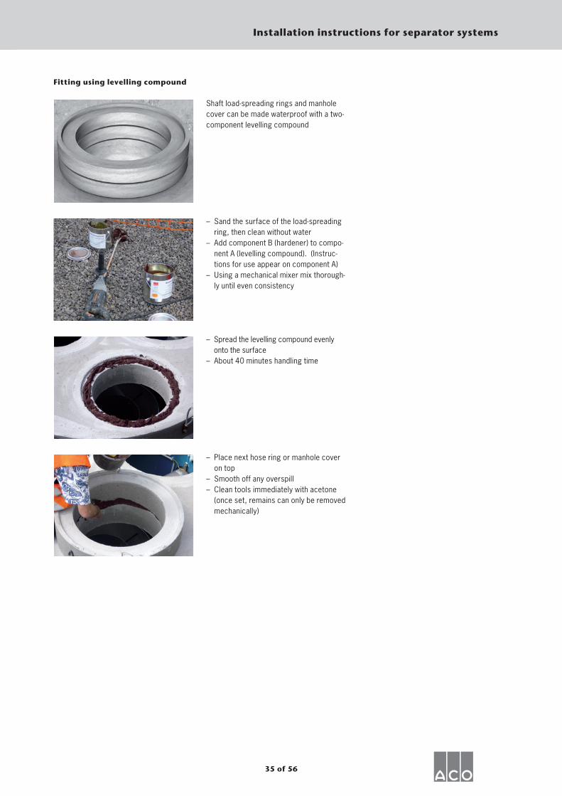
Fitting using levelling compound
Shaft load-spreading rings and manhole cover can be made waterproof with a two-component levelling compound
– Sand the surface of the load-spreading ring, then clean without water
– Add component B (hardener) to compo-nent A (levelling compound). (Instruc-tions for use appear on component A)
– Using a mechanical mixer mix thorough-ly until even consistency
– Spread the levelling compound evenly onto the surface
– About 40 minutes handling time
– Place next hose ring or manhole cover on top
– Smooth off any overspill– Clean tools immediately with acetone
(once set, remains can only be removed mechanically)
36 of 56
Installation instructions for separator systems
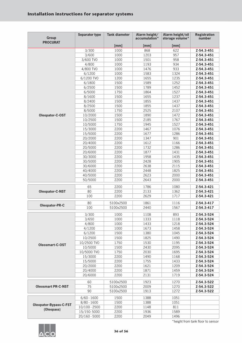
Group PROCURAT
Separator type Tank diameter
[mm]
Alarm height/accumulation*
[mm]
Alarm height/oil storage volume*
[mm]
Registration number
Oleopator-C-OST
3/300 1000 868 622 Z-54.3-4513/600 1000 1203 957 Z-54.3-451
3/600 TVO 1000 1501 958 Z-54.3-4514/800 1000 1193 934 Z-54.3-451
4/800 TVO 1000 1476 933 Z-54.3-4516/1200 1000 1583 1324 Z-54.3-451
6/1200 TVO 1200 1655 1235 Z-54.3-4516/1800 1500 1589 1252 Z-54.3-4516/2500 1500 1789 1452 Z-54.3-4516/5000 1750 1864 1527 Z-54.3-4518/1600 1500 1655 1237 Z-54.3-4518/2400 1500 1855 1437 Z-54.3-4518/2500 1500 1855 1437 Z-54.3-4518/5000 1750 2525 2107 Z-54.3-451
10/2000 1500 1890 1472 Z-54.3-45110/2500 1500 2185 1767 Z-54.3-45110/5000 1750 1945 1527 Z-54.3-45115/3000 2200 1467 1076 Z-54.3-45115/5000 2200 1677 1286 Z-54.3-45120/2000 2200 1347 901 Z-54.3-45120/4000 2200 1612 1166 Z-54.3-45120/5000 2200 1732 1286 Z-54.3-45120/6000 2200 1877 1431 Z-54.3-45130/3000 2200 1958 1435 Z-54.3-45130/5000 2200 2428 1905 Z-54.3-45130/6000 2200 2638 2115 Z-54.3-45140/4000 2200 2448 1825 Z-54.3-45140/5000 2200 2623 2000 Z-54.3-45150/5000 2200 2643 2000 Z-54.3-451
Oleopator-C-NST65 2200 1786 1080 Z-54.3-42180 2200 2133 1362 Z-54.3-421
100 2200 2629 1717 Z-54.3-421
Oleopator-PR-C80 5100x2500 1861 1116 Z-54.3-417
100 5100x2500 2440 1567 Z-54.3-417
Oleosmart-C-OST
3/300 1000 1108 893 Z-54.3-5243/650 1000 1333 1118 Z-54.3-5244/800 1000 1433 1218 Z-54.3-524
4/1200 1000 1673 1458 Z-54.3-5246/1200 1500 1380 1045 Z-54.3-524
10/2500 1500 1825 1490 Z-54.3-52410/2500 TVO 1750 1530 1195 Z-54.3-524
10/5000 1500 2430 2095 Z-54.3-52410/5000 TVO 1750 2030 1695 Z-54.3-524
15/3000 2200 1490 1168 Z-54.3-52415/5000 2200 1755 1433 Z-54.3-52420/2000 2200 1621 1209 Z-54.3-52420/4000 2200 1871 1459 Z-54.3-52420/6000 2200 2131 1719 Z-54.3-524
Oleosmart PR-C-NST60 5100x2500 1923 1270 Z-54.3-52275 5100x2500 2009 1270 Z-54.3-52290 5100x2500 1913 1272 Z-54.3-522
Oleopator-Bypass-C-FST (Oleopass)
6/60 - 1600 1500 1388 10518/80 - 1600 1500 1388 1051
10/100 - 2500 2200 1148 81115/150- 5000 2200 1936 158920/160 - 5000 2200 2049 1496
*height from tank floor to sensor

37 of 56
Installation instructions for separator systems
’H’-A
ufst
au
’H’-Ö
l
Länge x Breite
’H’-A
ufst
au
’H’-Ö
lBeckendurchmesser
’H’-A
ufst
au
’H’-Ö
l
Beckendurchmesser
Oleopator-C-OST
Oleosmart-C-OST
Oleopator-C-NST
Oleopator-PR-C
Oleosmart-PR-C-NST
Oleopator-Bypasss-C-FST
Beck diameter
Beck diameter
Impo
undm
ent
Öl
Impo
undm
ent
Oil
Length x Width
Impo
undm
ent
Öl
38 sur 56
Instructions de montage pour séparateurs
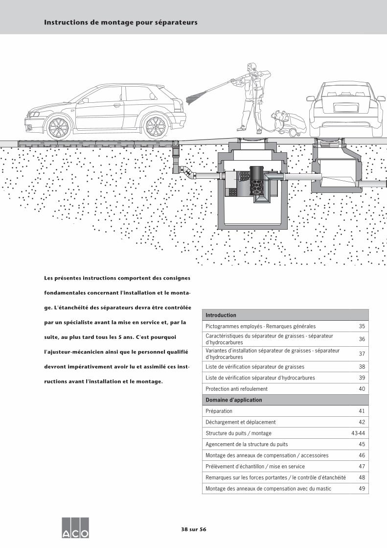
Les présentes instructions comportent des consignes
fondamentales concernant l'installation et le monta-
ge. L'étanchéité des séparateurs devra être contrôlée
par un spécialiste avant la mise en service et, par la
suite, au plus tard tous les 5 ans. C'est pourquoi
l'ajusteur-mécanicien ainsi que le personnel qualifié
devront impérativement avoir lu et assimilé ces inst-
ructions avant l'installation et le montage.
Introduction
Pictogrammes employés - Remarques générales 35
Caractéristiques du séparateur de graisses - séparateur d'hydrocarbures 36
Variantes d'installation séparateur de graisses - séparateur d'hydrocarbures 37
Liste de vérification séparateur de graisses 38
Liste de vérification séparateur d'hydrocarbures 39
Protection anti refoulement 40
Domaine d'application
Préparation 41
Déchargement et déplacement 42
Structure du puits / montage 43-44
Agencement de la structure du puits 45
Montage des anneaux de compensation / accessoires 46
Prélèvement d'échantillon / mise en service 47
Remarques sur les forces portantes / le contrôle d'étanchéité 48
Montage des anneaux de compensation avec du mastic 49
39 sur 56
Instructions de montage pour séparateurs
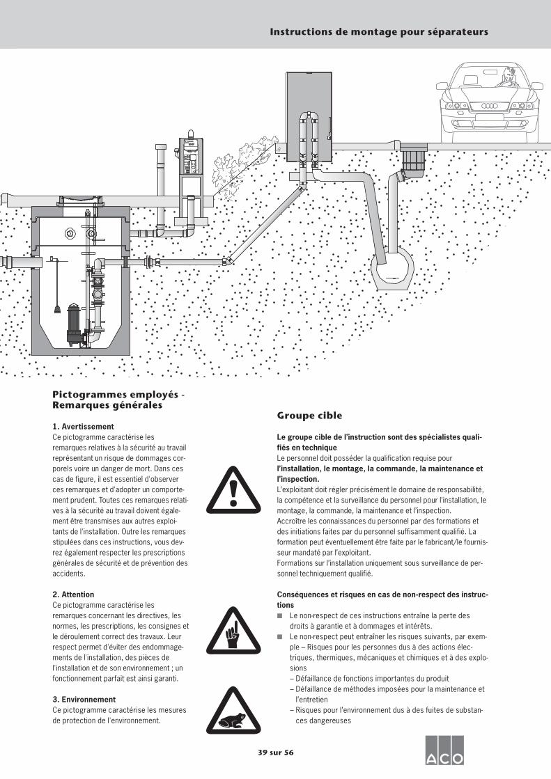
Pictogrammes employés - Remarques générales
1. AvertissementCe pictogramme caractérise les remarques relatives à la sécurité au travail représentant un risque de dommages cor-porels voire un danger de mort. Dans ces cas de figure, il est essentiel d'observer ces remarques et d'adopter un comporte-ment prudent. Toutes ces remarques relati-ves à la sécurité au travail doivent égale-ment être transmises aux autres exploi-tants de l'installation. Outre les remarques stipulées dans ces instructions, vous dev-rez également respecter les prescriptions générales de sécurité et de prévention des accidents.
2. AttentionCe pictogramme caractérise les remarques concernant les directives, les normes, les prescriptions, les consignes et le déroulement correct des travaux. Leur respect permet d'éviter des endommage-ments de l'installation, des pièces de l'installation et de son environnement ; un fonctionnement parfait est ainsi garanti.
3. Environnement Ce pictogramme caractérise les mesures de protection de l'environnement.
Groupe cible
Le groupe cible de l’instruction sont des spécialistes quali- fiés en techniqueLe personnel doit posséder la qualification requise pour l’installation, le montage, la commande, la maintenance et l’inspection.L’exploitant doit régler précisément le domaine de responsabilité, la compétence et la surveillance du personnel pour l’installation, le montage, la commande, la maintenance et l’inspection.Accroître les connaissances du personnel par des formations et des initiations faites par du personnel suffisamment qualifié. La formation peut éventuellement être faite par le fabricant/le fournis-seur mandaté par l’exploitant.Formations sur l’installation uniquement sous surveillance de per-sonnel techniquement qualifié.
Conséquences et risques en cas de non-respect des instruc-tions▪ Le non-respect de ces instructions entraîne la perte des
droits à garantie et à dommages et intérêts.▪ Le non-respect peut entraîner les risques suivants, par exem-
ple – Risques pour les personnes dus à des actions élec-triques, thermiques, mécaniques et chimiques et à des explo-sions
– Défaillance de fonctions importantes du produit – Défaillance de méthodes imposées pour la maintenance et
l’entretien – Risques pour l’environnement dus à des fuites de substan-
ces dangereuses
40 sur 56
Instructions de montage pour séparateurs
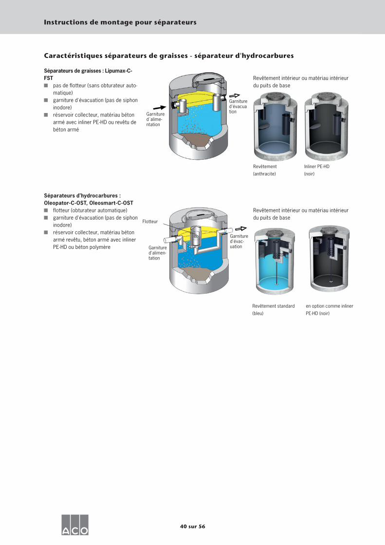
Caractéristiques séparateurs de graisses - séparateur d'hydrocarbures
Séparateurs de graisses : Lipumax-C-FST
pas de flotteur (sans obturateur auto-matique)
garniture d'évacuation (pas de siphon inodore)
réservoir collecteur, matériau béton armé avec inliner PE-HD ou revêtu de béton armé
Séparateurs d'hydrocarbures : Oleopator-C-OST, Oleosmart-C-OST
flotteur (obturateur automatique) garniture d'évacuation (pas de siphon
inodore) réservoir collecteur, matériau béton
armé revêtu, béton armé avec inliner PE-HD ou béton polymère
Revêtement intérieur ou matériau intérieur du puits de base
Revêtement
(anthracite)
Inliner PE-HD
(noir)
Revêtement intérieur ou matériau intérieur du puits de base
Revêtement standard
(bleu)
en option comme inliner
PE-HD (noir)
Garniture d´alime-ntation
Garniture d'évacuation
Garniture d'évac-uation
Flotteur
Garniture d'alimen-tation

41 sur 56
Instructions de montage pour séparateurs
Variantes d'installation - séparateur de graisses
Lipumax-C-FST
PS
SF FA PNS
SF FA PNS
FA/SF PNS
FA/SF PNS PS
S'il s'agit d'une grande installation, une division en flux partiels est possible:
VSSF FA
SF FASaS PS
Lors de la division en flux partiels, il faudra veil-ler à ce que le raccord d'alimentation soit de même niveau en aval du distributeur des eaux.
Légende SF Débourdeur FA Séparateur de graisses FA/SF Séparateur de graisses avec débourdeur intégré PNS Puits de prélèvement d'échantillon PS Station de pompage VS Puits de distribution SaS Puits de collecte
Oleopator-C-OSTOleosmart-C-OST
PS
Variantes d'installation séparateur d'hydrocarbures
SF LFA PNS
SF LFA PNS
LFA/SF PNS
LFA/SF PNS PS
Il est possible de combiner des séparateurs de classe I et de classe II.
S'il s'agit d'une grande installation, une division en flux partiels est possible:
VSSF LFA
SF LFASaS PS
Lors de la division en flux par-tiels, il faudra veiller à ce que le raccord d'alimentation soit
de même niveau en aval du distributeur des eaux.
Légende SF Débourdeur LFA Séparateur d'hydrocarbures L FA/SF Séparateur d'hydrocarbures avec débourdeur intégré PNS Puits de prélèvement d'échantillon PS Station de pompage VS Puits de distribution SaS Puits de collecte
42 sur 56
Instructions de montage pour séparateurs
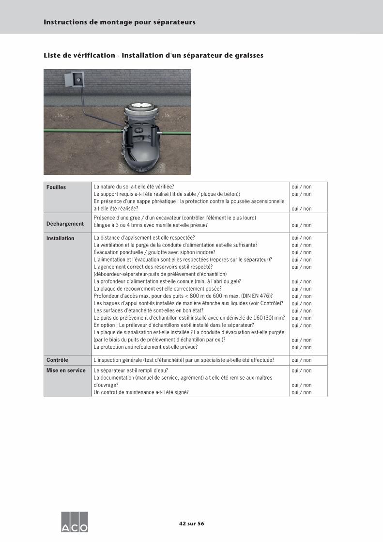
Fouilles La nature du sol a-t-elle été vérifiée? Le support requis a-t-il été réalisé (lit de sable / plaque de béton)? En présence d'une nappe phréatique : la protection contre la poussée ascensionnelle a-t-elle été réalisée?
oui / non oui / non
oui / non
Déchargement Présence d'une grue / d'un excavateur (contrôler l'élément le plus lourd) Élingue à 3 ou 4 brins avec manille est-elle prévue? oui / non
Installation La distance d'apaisement est-elle respectée? La ventilation et la purge de la conduite d'alimentation est-elle suffisante? Évacuation ponctuelle / goulotte avec siphon inodore? L'alimentation et l'évacuation sont-elles respectées (repères sur le séparateur)? L'agencement correct des réservoirs est-il respecté? (débourdeur-séparateur-puits de prélèvement d'échantillon) La profondeur d'alimentation est-elle connue (min. à l'abri du gel)? La plaque de recouvrement est-elle correctement posée? Profondeur d'accès max. pour des puits < 800 m de 600 m max. (DIN EN 476)? Les bagues d'appui sont-ils installés de manière étanche aux liquides (voir Contrôle)? Les surfaces d'étanchéité sont-elles en bon état? Le puits de prélèvement d'échantillon est-il installé avec un dénivelé de 160 (30) mm? En option : Le préleveur d'échantillons est-il installé dans le séparateur? La plaque de signalisation est-elle installée ? La conduite d'évacuation est-elle purgée (par le biais du puits de prélèvement d'échantillon par ex.)? La protection anti refoulement est-elle prévue?
oui / non oui / non oui / non oui / non oui / non
oui / non oui / non oui / non oui / non oui / non oui / non oui / non
oui / non oui / non
Contrôle L'inspection générale (test d'étanchéité) par un spécialiste a-t-elle été effectuée? oui / non
Mise en service Le séparateur est-il rempli d'eau? La documentation (manuel de service, agrément) a-t-elle été remise aux maîtres d'ouvrage? Un contrat de maintenance a-t-il été signé?
oui / non oui / non oui / non
Liste de vérification - Installation d'un séparateur de graisses

43 sur 56
Instructions de montage pour séparateurs
Fouilles La nature du sol a-t-elle été vérifiée? Le support requis a-t-il été réalisé (lit de sable / plaque de béton)? En présence d'une nappe phréatique: la protection contre la poussée ascensionnelle a-t-elle été réalisée?
oui / non oui / non
oui / non
Déchargement Présence d'une grue / d'un excavateur (contrôler l'élément le plus lourd) Élingue à 3 ou 4 brins avec manille est-elle prévue? oui / non
Installation Évacuation ponctuelle / goulotte sans siphon inodore? L'alimentation et l'évacuation sont-elles respectées (repères sur le séparateur)? L'agencement correct des réservoirs est-il respecté? (débourdeur-séparateur-puits de prélèvement d'échantillon) La profondeur d'alimentation est-elle connue (min. à l'abri du gel)? Le tuyau d'alimentation / les garnitures d'étanchéité sont-ils résistants à l'huile? La plaque de recouvrement est-elle correctement posée? Profondeur d'accès max. pour des puits < 800 m de 600 m max. (DIN EN 476)? Les bagues d'appui sont-ils installés de manière étanche aux liquides (voir Contrôle)? Les surfaces d'étanchéité sont-elles en bon état? Un système d'alarme est-il installée (obligatoire en vertu de la norme DIN EN 858-1)?Le puits de prélèvement d'échantillon est-il installé avec un dénivelé de 160 (30) mm? En option : Le préleveur d'échantillons est-il installé dans le séparateur? La plaque de signalisation est-elle installée? La conduite d'évacuation est-elle purgée (par le biais du puits de prélèvement d'échantillon par ex.)? La protection anti refoulement est-elle prévue?
oui / non oui / non oui / non
oui / non oui / non oui / non oui / non oui / non oui / non oui / non oui / non oui / non oui / non
oui / non oui / non
Contrôle L'inspection générale (test d'étanchéité) par un spécialiste a-t-elle été effectuée? oui / non
Mise en service Le flotteur a-t-il été retiré avant le remplissage? Le flotteur et l'unité coalescente ont-ils été mis en place après le remplissage? La documentation (manuel de service, agrément) a-t-elle été remise aux maîtres d'ouvrage? Un contrat de maintenance a-t-il été signé?
oui / non oui / non
oui / non oui / non
Liste de vérification - Pose d'un séparateur d'hydrocarbures
44 sur 56
Instructions de montage pour séparateurs
Le montage devra être réalisé par une entreprise spécialisée qualifiée dans le respect des normes et prescriptions respec-tivement applicables.
Raccordement aux égouts Raccorder les séparateurs aux canalisations des eaux usées et des eaux mixtes. Tout autre type de raccord devra recevoir l'aval des autorités compétentes. Le
raccordement aux égouts devra se faire en conformité avec, entre autres, les normes DIN EN 12056, DIN EN 752 et DIN 1986-100. Dans ce cas, il faudra alors accorder une attention particulière à la position d'installation du séparateur par rapport au niveau de refoulement (norma-
lement le bord supérieur de la route, au point de raccordement). Si le séparateur, avec son niveau d'eau en phase de repos, se situe en dessous du niveau de refoule-ment, il faudra prévoir des mesures de pro-tection anti refoulement (par ex. en instal-lant une station de pompage avec boucle de refoulement). En cas de remplissage et d'étaiement des conduites de raccordement et de liaison, appliquer la norme DIN 4033. Si nécessaire, prévoir une protection anti corrosion pour les conduites enterrées. Observer la norme DIN 30672 Partie 1. Doter les conduites d'évacuation des sépa-rateurs d'une protection anti aspiration (par exemple par un puits ou une ventilation adé-quate de la conduite, cf. aussi la norme DIN EN 858 Partie 1 § 6.5.1).
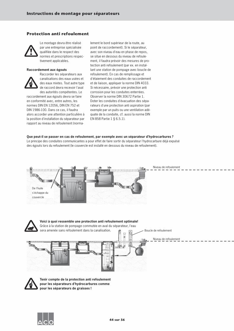
Que peut-il se passer en cas de refoulement, par exemple avec un séparateur d'hydrocarbures ? Le principe des conduites communicantes a pour effet de faire sortir du séparateur l'hydrocarbure déjà expulsé des égouts lors du refoulement (le couvercle est installé en dessous du niveau de refoulement).
Voici à quoi ressemble une protection anti refoulement optimale! Grâce à la station de pompage commutée en aval du séparateur, l'eau sera amenée sans refoulement dans la canalisation.
Niveau de refoulement
Niveau de refoulement
Boucle de refoulement
De l'huile
s'échappe du
couvercle
Tenir compte de la protection anti refoulement pour les séparateurs d'hydrocarbures comme pour les séparateurs de graisses !
Protection anti refoulement
45 sur 56
Instructions de montage pour séparateurs
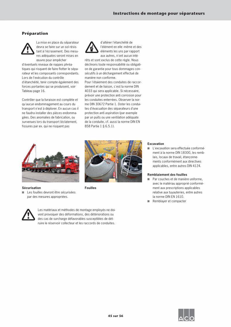
Excavation L'excavation sera effectuée conformé-
ment à la norme DIN 18300, les remb-lais, locaux de travail, étançonne-ments conformément aux directives applicables, entre autres DIN 4124.
Remblaiement des fouilles Par couches et de manière uniforme,
avec le matériau approprié conformé-ment aux prescriptions applicables relative aux tuyauteries, entre autres la norme DIN EN 1610.
Remblayer et compacter
Préparation
La mise en place du séparateur devra se faire sur un sol résis-tant à l'écrasement. Des mesu-res adéquates seront mises en œuvre pour empêcher
d'éventuels niveaux de nappes phréa-tiques qui risquent de faire flotter le sépa-rateur et les composants correspondants. Lors de l'exécution du contrôle d'étanchéité, tenir compte également des forces portantes qui se produisent, voir Tableau page 16. Contrôler que la livraison est complète et qu'aucun endommagement au cours du transport n'est à déplorer. En aucun cas il ne faudra installer des pièces endomma-gées. Des anomalies de fabrication, ou survenues lors du transport (éclatement, fissures par ex. qui ne risquent pas
d'altérer l'étanchéité de l'élément en elle -même et des éléments les uns par rapport aux autres, n'ont aucun inté-
rêts et sont exclus de cette règle. Nous déclinons toute responsabilité ou obligati-on de garantie pour tous dommages con-sécutifs à un déchargement effectué de manière non conforme. Pour l'étaiement des conduites de raccor-dement et de liaison, c'est la norme DIN 4033 qui sera applicable. Si nécessaire, prévoir une protection anti corrosion pour les conduites enterrées. Observer la nor-me DIN 30672 Partie 1. Doter les condui-tes d'évacuation des séparateurs d'une protection anti aspiration (par exemple par un puits ou une ventilation adéquate de la conduite, cf. aussi la norme DIN EN 858 Partie 1 § 6.5.1).
Sécurisation Les fouilles devront être sécurisées
par des mesures appropriées.
Fouilles
Les matériaux et méthodes de montage employés ne doi-vent provoquer des déformations, des détériorations ou des cas de surcharge défavorables susceptibles de dét-ruire le réservoir collecteur et les raccords de conduites.
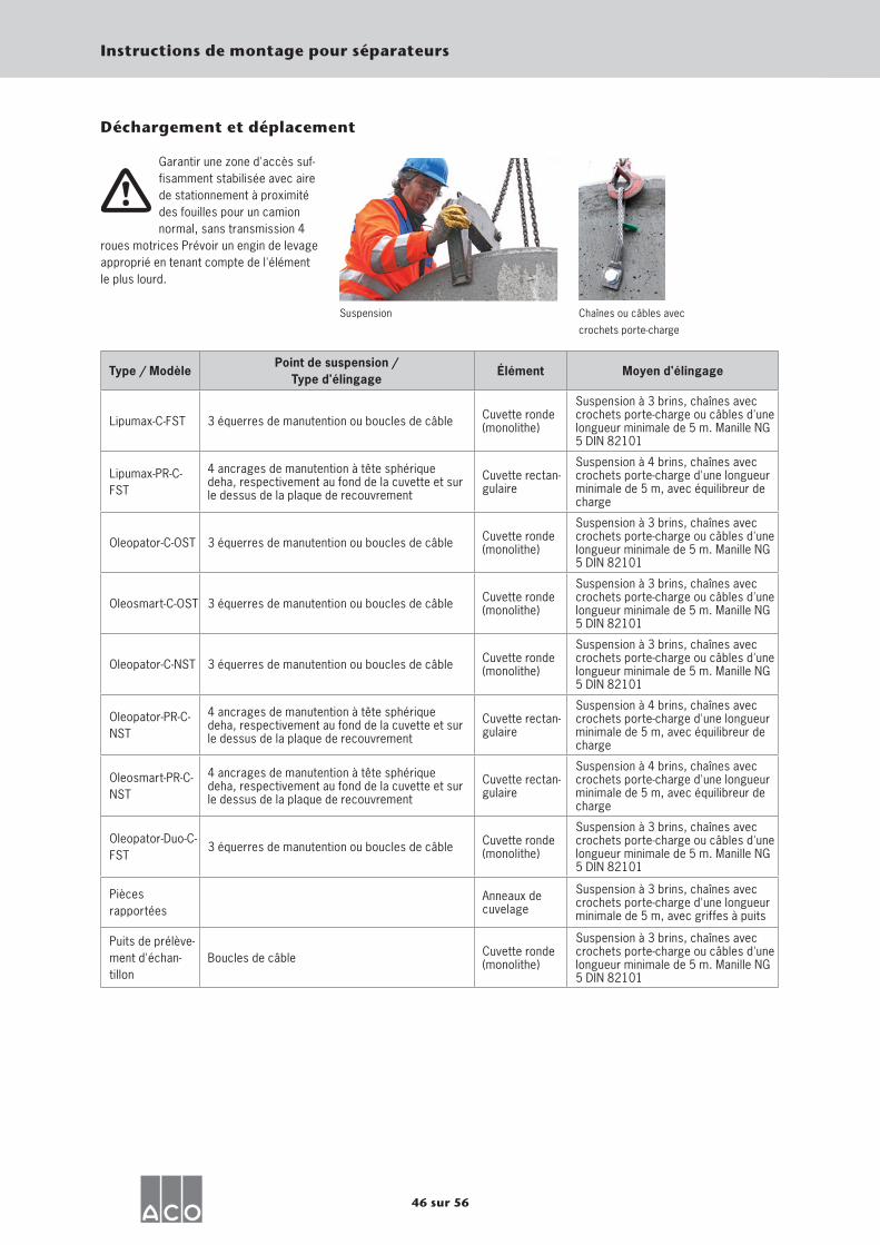
46 sur 56
Instructions de montage pour séparateurs
Garantir une zone d'accès suf-fisamment stabilisée avec aire de stationnement à proximité des fouilles pour un camion normal, sans transmission 4
roues motrices Prévoir un engin de levage approprié en tenant compte de l'élément le plus lourd.
Type / Modèle Point de suspension /
Type d'élingage Élément Moyen d'élingage
Lipumax-C-FST 3 équerres de manutention ou boucles de câble Cuvette ronde (monolithe)
Suspension à 3 brins, chaînes avec crochets porte-charge ou câbles d'une longueur minimale de 5 m. Manille NG 5 DIN 82101
Lipumax-PR-C-FST
4 ancrages de manutention à tête sphérique deha, respectivement au fond de la cuvette et sur le dessus de la plaque de recouvrement
Cuvette rectan-gulaire
Suspension à 4 brins, chaînes avec crochets porte-charge d'une longueur minimale de 5 m, avec équilibreur de charge
Oleopator-C-OST 3 équerres de manutention ou boucles de câble Cuvette ronde (monolithe)
Suspension à 3 brins, chaînes avec crochets porte-charge ou câbles d'une longueur minimale de 5 m. Manille NG 5 DIN 82101
Oleosmart-C-OST 3 équerres de manutention ou boucles de câble Cuvette ronde (monolithe)
Suspension à 3 brins, chaînes avec crochets porte-charge ou câbles d'une longueur minimale de 5 m. Manille NG 5 DIN 82101
Oleopator-C-NST 3 équerres de manutention ou boucles de câble Cuvette ronde (monolithe)
Suspension à 3 brins, chaînes avec crochets porte-charge ou câbles d'une longueur minimale de 5 m. Manille NG 5 DIN 82101
Oleopator-PR-C-NST
4 ancrages de manutention à tête sphérique deha, respectivement au fond de la cuvette et sur le dessus de la plaque de recouvrement
Cuvette rectan-gulaire
Suspension à 4 brins, chaînes avec crochets porte-charge d'une longueur minimale de 5 m, avec équilibreur de charge
Oleosmart-PR-C-NST
4 ancrages de manutention à tête sphérique deha, respectivement au fond de la cuvette et sur le dessus de la plaque de recouvrement
Cuvette rectan-gulaire
Suspension à 4 brins, chaînes avec crochets porte-charge d'une longueur minimale de 5 m, avec équilibreur de charge
Oleopator-Duo-C-FST
3 équerres de manutention ou boucles de câble Cuvette ronde (monolithe)
Suspension à 3 brins, chaînes avec crochets porte-charge ou câbles d'une longueur minimale de 5 m. Manille NG 5 DIN 82101
Pièces rapportées
Anneaux de cuvelage
Suspension à 3 brins, chaînes avec crochets porte-charge d'une longueur minimale de 5 m, avec griffes à puits
Puits de prélève-ment d'échan-tillon
Boucles de câble Cuvette ronde (monolithe)
Suspension à 3 brins, chaînes avec crochets porte-charge ou câbles d'une longueur minimale de 5 m. Manille NG 5 DIN 82101
Suspension Chaînes ou câbles avec
crochets porte-charge
Déchargement et déplacement
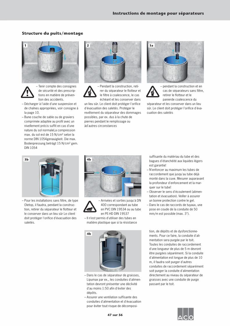
47 sur 56
Instructions de montage pour séparateurs
1
– Tenir compte des consignes de sécurité et des prescrip-tions en matière de préven-tion des accidents.
– Décharger à l'aide d'une suspension et de chaînes appropriées, voir consigne à la page 10.
– Bune couche de sable ou de graviers comprimée adaptée au profil avec un nivellement précis suffit en cas d'une nature du sol normaleLa compression max. du sol est de 15 N/cm² selon la norme DIN 1054genauigkeit. Die max. Bodenpressung beträgt 15 N/cm² gem. DIN 1054
2
– Pendant la construction, reti-rer du séparateur le flotteur et le filtre à coalescence, le cas échéant et les conserver dans
un lieu sûr. Le client doit protéger l'orifice d'évacuation des saletés. Protéger le revêtement du séparateur des dommages possibles, par ex. dus à la chute de pierres pendant le remplissage ou àd'autres circonstances
– pendant la construction et en cas de séparateurs sans filtre, retirer le flotteur et le panierde coalescence du
séparateur et les conserver dans un lieu sûr. Le client doit protéger l'orifice d'éva-cuation des saletés
– Arrivées et sorties jusqu'à DN 400 correspondant au tube en PVC DIN 19534 ou au tube en PE-HD DIN 19537
– Il n’est permis d'utiliser des tubes en matière plastique que si la résistance
Structure du puits/montage
– Pour les installations sans filtre, de type Oletop, il faudra, pendant la construc-tion, retirer du séparateur le flotteur et le conserver dans un lieu sûr Le client doit protéger l'orifice d'évacuation des saletés.
– Dans le cas de séparateur de graisses, Lipumax par ex., les conduites d'alimen-tation devront présenter une déclivité d'au moins 1:50 afin d'éviter des dépôts.
– Assurer une ventilation suffisante des conduites d'alimentation et d'évacuation pour éviter tout risque de décomposi-
suffisante du matériau du tube et des bagues d'étanchéité aux liquides légers est garantie!
– N'enfoncer au maximum les tubes de raccordement que jusqu'au tube déjà monté dans la cuve. Mesurer auparavant la profondeur d'enfoncement et la mar-quer sur le tube!
– Observer le sens d'écoulement (alimen-tation et évacuation). Veiller à assurer un bonne protection contre le gel.
– Dans le cas de raccords de tuyaux, une pose en coude de la conduite de 50 mm/m est possible (max. 3°).
tion, de dépôts et de dysfonctionne-ments. Pour ce faire, la conduite d'ali-mentation sera purgée par le toit. Toutes les conduites de raccordement d'une longueur de plus de 5 m devront être purgées séparément. Si la conduite d'alimentation est longue de plus de 10 m, il faudra soit purger d'autres conduites de raccordement séparément soit purger la conduite d'alimentation directement au niveau du séparateur de graisses avec une conduite de purge passant par le toit.
4b
3a
4b
3b
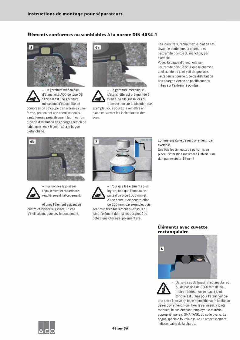
48 sur 56
Instructions de montage pour séparateurs
Éléments conformes ou semblables à la norme DIN 4034-1
– Dans le cas de bassins rectangulaires ou de bassins de 2200 mm de dia-mètre intérieur, un anneau à joint torique est utilisé pour l'étanchéifica-
tion entre la cuve de base monolithique et la plaque de recouvrement. Pour fixer les anneaux à joints toriques, le cas échéant, employer le matériau approprié, par ex. SIKA TANK, ou colle cyano. La bague spéciale fournie assure un amortissement indispensable de la charge.
8
Éléments avec cuvette rectangulaire
– La garniture mécanique d'étanchéité ACO de type DS SDVseal est une garniture mécanique d'étanchéité de
compression de coupe transversale cunéi-forme, présentant une chemise coulis-sante fermée préalablement lubrifiée. Un tube de distribution des charges rempli de sable quartzeux fin est fixé à la bague d'étanchéité.
– La garniture mécanique d'étanchéité est pré-montée à l'usine. Si elle glisse lors du transport ou sur le chantier, par
exemple, vous pouvez la remettre en place en suivant les indications ci-des-sous.
Les jours frais, réchauffez le joint en net-toyant le conteneur, la chambre et l'extrémité pointue du manchon, par exemple.Posez la bague d'étanchéité sur l'extrémité pointue pour que la chemise coulissante du joint soit dirigée vers l'extérieur et que le tube de distribution des charges vienne se positionner au milieu sur l'extrémité pointue.
– Positionnez le joint sur l'épaulement et répartissez régulièrement l'allongement.
Alignez l'élément suivant au centre et laissez-le glisser. En cas d'inclinaison, poussez-le doucement.
– Pour que les éléments plus légers, tels que l'anneau de puits d'un ø de 1000 mm et d'une hauteur de construction de 250 mm, par exemple, puis-
sent être tirés facilement au-dessus du joint, l'élément doit, si nécessaire, être doté d'une charge supplémentaire,
comme une dalle de recouvrement, par exemple.Une fois les anneaux de puits mis en place, l'interstice maximal à l'intérieur ne doit pas excéder 15 mm !
5 56a
56b 7
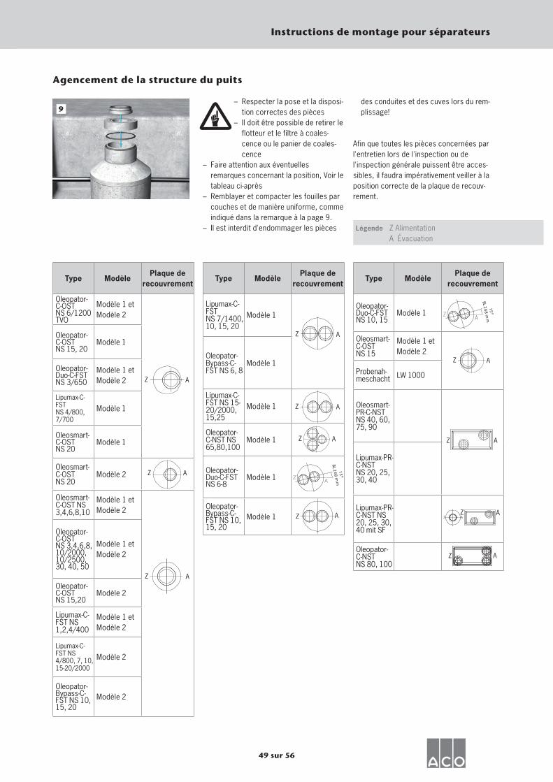
49 sur 56
Instructions de montage pour séparateurs
Éléments avec cuvette rectangulaire
– Respecter la pose et la disposi-tion correctes des pièces
– Il doit être possible de retirer le flotteur et le filtre à coales-cence ou le panier de coales-cence
– Faire attention aux éventuelles remarques concernant la position, Voir le tableau ci-après
– Remblayer et compacter les fouilles par couches et de manière uniforme, comme indiqué dans la remarque à la page 9.
– Il est interdit d'endommager les pièces
9
Agencement de la structure du puits
Légende
Afin que toutes les pièces concernées par l'entretien lors de l'inspection ou de l'inspection générale puissent être acces-sibles, il faudra impérativement veiller à la position correcte de la plaque de recouv-rement.
Z Alimentation A Évacuation
des conduites et des cuves lors du rem-plissage!
Type Modèle Plaque de
recouvrement
Oleopator-C-OSTNS 6/1200TVO
Modèle 1 et Modèle 2
Oleopator-C-OSTNS 15, 20
Modèle 1
Oleopator-Duo-C-FST NS 3/650
Modèle 1 et Modèle 2
Lipumax-C-FSTNS 4/800, 7/700
Modèle 1
Oleosmart-C-OSTNS 20
Modèle 1
Oleosmart-C-OSTNS 20
Modèle 2
Oleosmart-C-OST NS 3,4,6,8,10
Modèle 1 et Modèle 2
Oleopator-C-OST NS 3,4,6,8, 10/2000, 10/2500, 30, 40, 50
Modèle 1 et Modèle 2
Oleopator-C-OSTNS 15,20
Modèle 2
Lipumax-C-FST NS 1,2,4/400
Modèle 1 et Modèle 2
Lipumax-C-FST NS 4/800, 7, 10,15-20/2000
Modèle 2
Oleopator-Bypass-C-FST NS 10, 15, 20
Modèle 2
Z A
A
Z A
Z A
Z A
Lipumax-C-FSTNS 7/1400, 10, 15, 20
Modèle 1
Oleopator-Bypass-C-FST NS 6, 8
Modèle 1
Lipumax-C-FST NS 15- 20/2000, 15,25
Modèle 1
Oleopator-C-NST NS 65,80,100
Modèle 1
Oleopator-Duo-C-FST NS 6-8
Modèle 1
Oleopator-Bypass-C-FST NS 10, 15, 20
Modèle 1
Type Modèle Plaque de
recouvrement Type Modèle
Plaque de recouvrement
Oleopator-Duo-C-FST NS 10, 15
Modèle 1
Oleosmart-C-OSTNS 15
Modèle 1 et Modèle 2
Probenah-meschacht LW 1000
Oleosmart-PR-C-NST NS 40, 60, 75, 90
Lipumax-PR-C-NSTNS 20, 25, 30, 40
Lipumax-PR-C-NST NS 20, 25, 30, 40 mit SF
Oleopator-C-NST NS 80, 100
Z A
15
BL 26
8 m
m
15
BL 26
8 m
m
Z A
Z A
AZ
Z A
Z
Z A
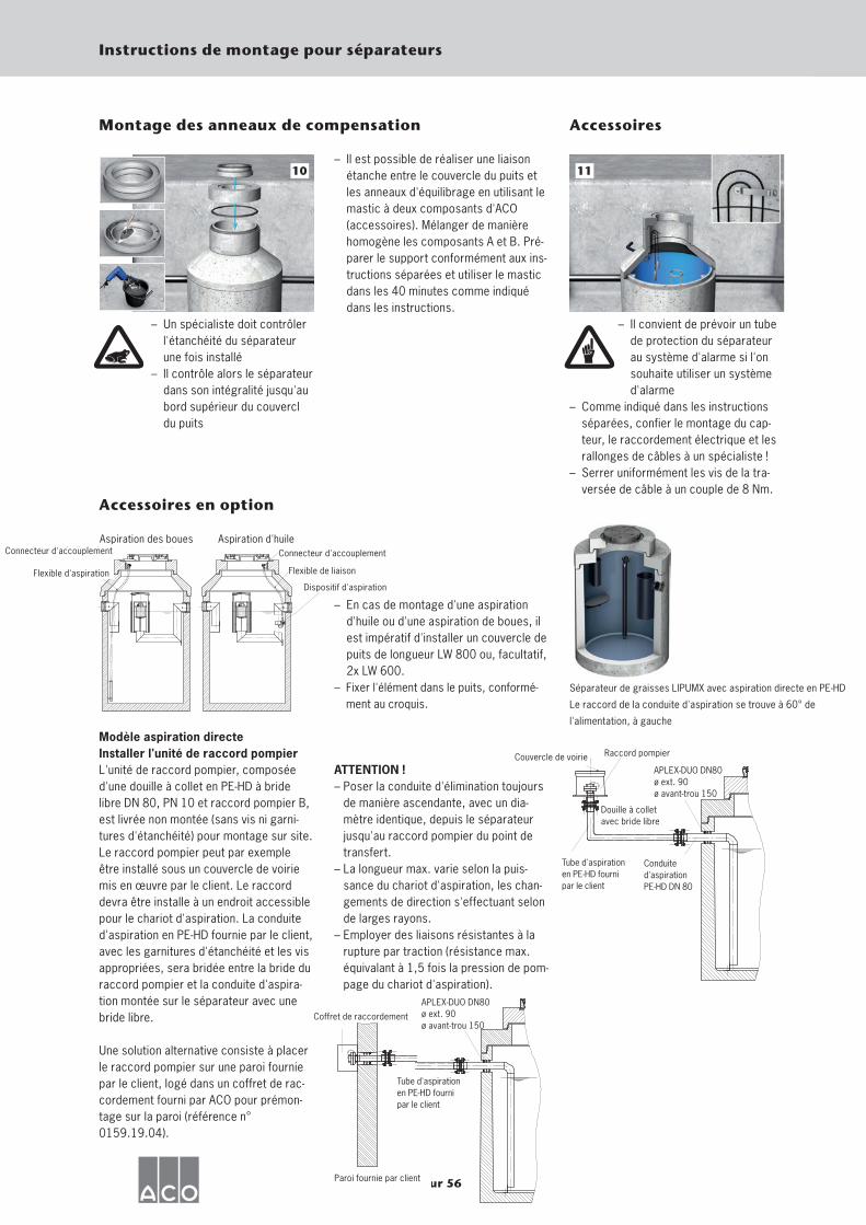
50 sur 56
Instructions de montage pour séparateurs
– Un spécialiste doit contrôler l'étanchéité du séparateur une fois installé
– Il contrôle alors le séparateur dans son intégralité jusqu'au bord supérieur du couvercl du puits
10
Montage des anneaux de compensation
– Il est possible de réaliser une liaison étanche entre le couvercle du puits et les anneaux d'équilibrage en utilisant le mastic à deux composants d'ACO (accessoires). Mélanger de manière homogène les composants A et B. Pré-parer le support conformément aux ins-tructions séparées et utiliser le mastic dans les 40 minutes comme indiqué dans les instructions.
– Il convient de prévoir un tube de protection du séparateur au système d'alarme si l'on souhaite utiliser un système d'alarme
– Comme indiqué dans les instructions séparées, confier le montage du cap-teur, le raccordement électrique et les rallonges de câbles à un spécialiste !
– Serrer uniformément les vis de la tra-versée de câble à un couple de 8 Nm.
11
Accessoires
Accessoires en option
– En cas de montage d'une aspiration d'huile ou d'une aspiration de boues, il est impératif d'installer un couvercle de puits de longueur LW 800 ou, facultatif, 2x LW 600.
– Fixer l'élément dans le puits, conformé-ment au croquis.
Modèle aspiration directe Installer l'unité de raccord pompier L'unité de raccord pompier, composée d'une douille à collet en PE-HD à bride libre DN 80, PN 10 et raccord pompier B, est livrée non montée (sans vis ni garni-tures d'étanchéité) pour montage sur site. Le raccord pompier peut par exemple être installé sous un couvercle de voirie mis en œuvre par le client. Le raccord devra être installe à un endroit accessible pour le chariot d'aspiration. La conduite d'aspiration en PE-HD fournie par le client, avec les garnitures d'étanchéité et les vis appropriées, sera bridée entre la bride du raccord pompier et la conduite d'aspira-tion montée sur le séparateur avec une bride libre.
Une solution alternative consiste à placer le raccord pompier sur une paroi fournie par le client, logé dans un coffret de rac-cordement fourni par ACO pour prémon-tage sur la paroi (référence n° 0159.19.04).
ATTENTION ! – Poser la conduite d'élimination toujours
de manière ascendante, avec un dia-mètre identique, depuis le séparateur jusqu'au raccord pompier du point de transfert.
– La longueur max. varie selon la puis-sance du chariot d'aspiration, les chan-gements de direction s'effectuant selon de larges rayons.
– Employer des liaisons résistantes à la rupture par traction (résistance max. équivalant à 1,5 fois la pression de pom-page du chariot d'aspiration).
Aspiration des boues Aspiration d'huile Connecteur d'accouplement
Flexible d'aspiration
Connecteur d'accouplement
Dispositif d'aspiration
Flexible de liaison
Séparateur de graisses LIPUMX avec aspiration directe en PE-HD
Le raccord de la conduite d'aspiration se trouve à 60° de
l'alimentation, à gauche
Douille à collet avec bride libre
APLEX-DUO DN80 ø ext. 90 ø avant-trou 150
Couvercle de voirie Raccord pompier
Conduite d'aspiration PE-HD DN 80
Tube d'aspiration en PE-HD fourni par le client
Paroi fournie par client
Coffret de raccordement
APLEX-DUO DN80ø ext. 90ø avant-trou 150
Tube d'aspiration en PE-HD fourni par le client
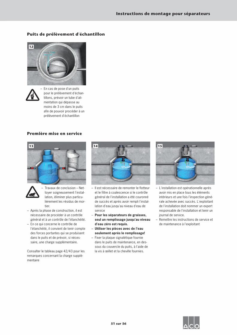
51 sur 56
Instructions de montage pour séparateurs
Puits de prélèvement d'échantillon
– En cas de pose d'un puits pour le prélèvement d'échan-tillons, prévoir un tube d'ali-mentation qui dépasse au moins de 3 cm dans le puits afin de pouvoir procéder à un prélèvement d'échantillon
12
– Travaux de conclusion – Net-toyer soigneusement l'instal-lation, éliminer plus particu-lièrement les résidus de mor-tier.
– Après la phase de construction, il est nécessaire de procéder à un contrôle général et à un contrôle de l'étanchéité.
– En ce qui concerne le contrôle de l'étanchéité, il convient de tenir compte des forces portantes qui se produisent dans le puits et de prévoir, si néces-saire, une charge supplémentaire.
Consulter le tableau page 42/43 pour lesremarques concernant la charge supplé-mentaire
13
Première mise en service
– Il est nécessaire de remonter le flotteur et le filtre à coalescence si le contrôle général de l'installation a été couronné de succès et après avoir rempli l'instal-lation d'eau jusqu'au niveau d'eau de service
– Pour les séparateurs de graisses, seul un remplissage jusqu'au niveau d'eau zéro est requis.
– Utiliser les pièces avec de l'eau seulement après le remplissage!
– Fixer la plaque signalétique fournie dans le puits de maintenance, en des-sous du couvercle du puits, à l'aide de la vis à œillet et la cheville fournies.
14
– L'installation est opérationnelle après avoir mis en place tous les éléments intérieurs et une fois l'inspection géné-rale achevée avec succès. L'exploitant de l'installation doit nommer un expert responsable de l'installation et tenir un journal de service.
– Remettre les instructions de service et de maintenance à l'exploitant
15
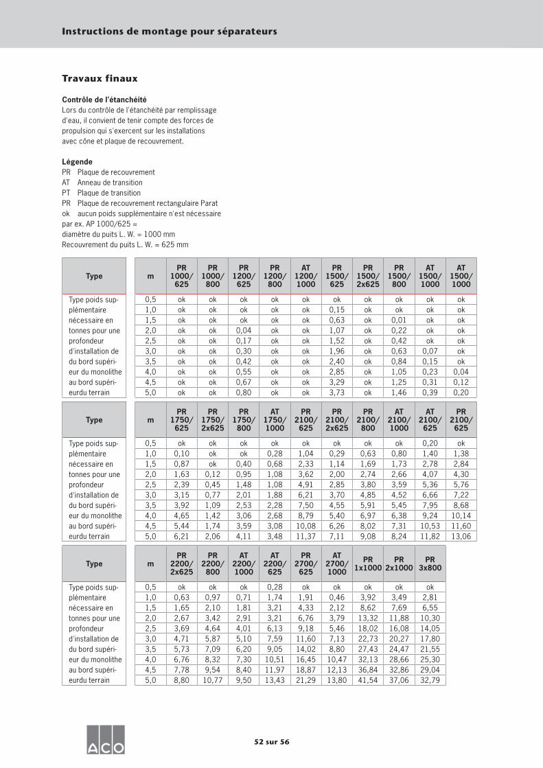
52 sur 56
Instructions de montage pour séparateurs
Travaux finaux
Contrôle de l'étanchéitéLors du contrôle de l'étanchéité par remplissaged'eau, il convient de tenir compte des forces depropulsion qui s'exercent sur les installationsavec cône et plaque de recouvrement.
LégendePR Plaque de recouvrementAT Anneau de transitionPT Plaque de transitionPR Plaque de recouvrement rectangulaire Paratok aucun poids supplémentaire n'est nécessairepar ex. AP 1000/625 = diamètre du puits L. W. = 1000 mmRecouvrement du puits L. W. = 625 mm
Type mPR
1000/625
PR1000/800
PR1200/625
PR1200/800
AT1200/1000
PR1500/625
PR1500/2x625
PR1500/800
AT1500/1000
AT1500/1000
Type poids sup-plémentaire nécessaire en tonnes pour une profondeur d'installation de du bord supéri-eur du monolithe au bord supéri-eurdu terrain
0,5 ok ok ok ok ok ok ok ok ok ok1,0 ok ok ok ok ok 0,15 ok ok ok ok1,5 ok ok ok ok ok 0,63 ok 0,01 ok ok2,0 ok ok 0,04 ok ok 1,07 ok 0,22 ok ok2,5 ok ok 0,17 ok ok 1,52 ok 0,42 ok ok3,0 ok ok 0,30 ok ok 1,96 ok 0,63 0,07 ok3,5 ok ok 0,42 ok ok 2,40 ok 0,84 0,15 ok4,0 ok ok 0,55 ok ok 2,85 ok 1,05 0,23 0,044,5 ok ok 0,67 ok ok 3,29 ok 1,25 0,31 0,125,0 ok ok 0,80 ok ok 3,73 ok 1,46 0,39 0,20
Type mPR
1750/625
PR1750/2x625
PR1750/800
AT1750/1000
PR2100/625
PR2100/2x625
PR2100/800
AT2100/1000
AT2100/625
PR2100/625
Type poids sup-plémentaire nécessaire en tonnes pour une profondeur d'installation de du bord supéri-eur du monolithe au bord supéri-eurdu terrain
0,5 ok ok ok ok ok ok ok ok 0,20 ok1,0 0,10 ok ok 0,28 1,04 0,29 0,63 0,80 1,40 1,381,5 0,87 ok 0,40 0,68 2,33 1,14 1,69 1,73 2,78 2,842,0 1,63 0,12 0,95 1,08 3,62 2,00 2,74 2,66 4,07 4,302,5 2,39 0,45 1,48 1,08 4,91 2,85 3,80 3,59 5,36 5,763,0 3,15 0,77 2,01 1,88 6,21 3,70 4,85 4,52 6,66 7,223,5 3,92 1,09 2,53 2,28 7,50 4,55 5,91 5,45 7,95 8,684,0 4,65 1,42 3,06 2,68 8,79 5,40 6,97 6,38 9,24 10,144,5 5,44 1,74 3,59 3,08 10,08 6,26 8,02 7,31 10,53 11,605,0 6,21 2,06 4,11 3,48 11,37 7,11 9,08 8,24 11,82 13,06
Type mPR
2200/2x625
PR2200/800
AT2200/1000
AT2200/625
PR2700/625
AT2700/1000
PR1x1000
PR2x1000
PR3x800
Type poids sup-plémentaire nécessaire en tonnes pour une profondeur d'installation de du bord supéri-eur du monolithe au bord supéri-eurdu terrain
0,5 ok ok ok 0,28 ok ok ok ok ok1,0 0,63 0,97 0,71 1,74 1,91 0,46 3,92 3,49 2,811,5 1,65 2,10 1,81 3,21 4,33 2,12 8,62 7,69 6,552,0 2,67 3,42 2,91 3,21 6,76 3,79 13,32 11,88 10,302,5 3,69 4,64 4,01 6,13 9,18 5,46 18,02 16,08 14,053,0 4,71 5,87 5,10 7,59 11,60 7,13 22,73 20,27 17,803,5 5,73 7,09 6,20 9,05 14,02 8,80 27,43 24,47 21,554,0 6,76 8,32 7,30 10,51 16,45 10,47 32,13 28,66 25,304,5 7,78 9,54 8,40 11,97 18,87 12,13 36,84 32,86 29,045,0 8,80 10,77 9,50 13,43 21,29 13,80 41,54 37,06 32,79
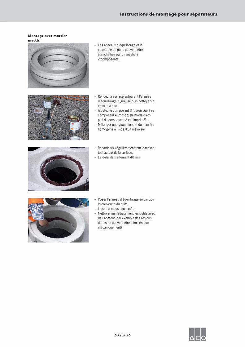
53 sur 56
Instructions de montage pour séparateurs
Montage avec mortiermastic
– Les anneaux d'équilibrage et le couvercle du puits peuvent être étanchéifiés par un mastic à 2 composants.
– Rendez la surface entourant l'anneau d'équilibrage rugueuse puis nettoyez-la ensuite à sec.
– Ajoutez le composant B (durcisseur) au composant A (mastic) (le mode d'em-ploi du composant A est imprimé).
– Mélanger énergiquement et de manière homogène à l'aide d'un malaxeur
– Répartissez régulièrement tout le mastic tout autour de la surface.
– Le délai de traitement 40 min
– Poser l'anneau d'équilibrage suivant ou le couvercle du puits
– Lisser la masse en excès– Nettoyer immédiatement les outils avec
de l'acétone par exemple (les résidus durcis ne peuvent être éliminés que mécaniquement)
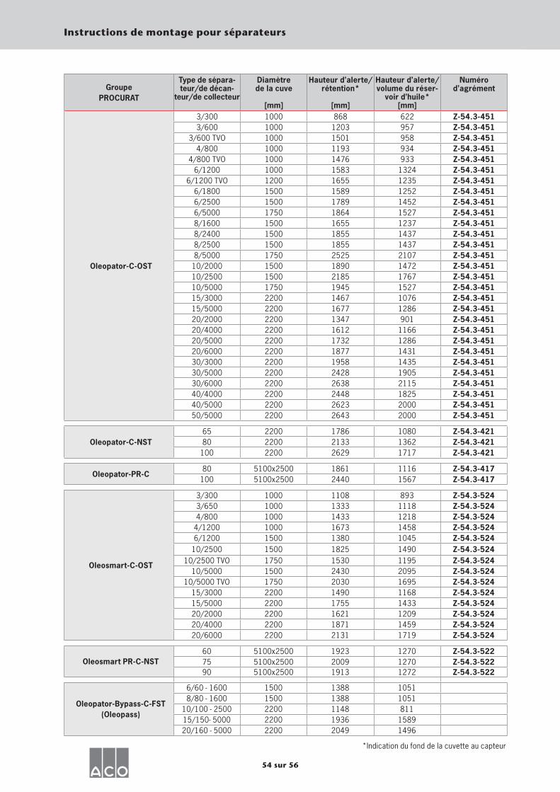
54 sur 56
Instructions de montage pour séparateurs
Groupe PROCURAT
Type de sépara-teur/de décan-
teur/de collecteur
Diamètre de la cuve
[mm]
Hauteur d’alerte/ rétention*
[mm]
Hauteur d’alerte/ volume du réser-
voir d’huile*[mm]
Numéro d’agrément
Oleopator-C-OST
3/300 1000 868 622 Z-54.3-4513/600 1000 1203 957 Z-54.3-451
3/600 TVO 1000 1501 958 Z-54.3-4514/800 1000 1193 934 Z-54.3-451
4/800 TVO 1000 1476 933 Z-54.3-4516/1200 1000 1583 1324 Z-54.3-451
6/1200 TVO 1200 1655 1235 Z-54.3-4516/1800 1500 1589 1252 Z-54.3-4516/2500 1500 1789 1452 Z-54.3-4516/5000 1750 1864 1527 Z-54.3-4518/1600 1500 1655 1237 Z-54.3-4518/2400 1500 1855 1437 Z-54.3-4518/2500 1500 1855 1437 Z-54.3-4518/5000 1750 2525 2107 Z-54.3-451
10/2000 1500 1890 1472 Z-54.3-45110/2500 1500 2185 1767 Z-54.3-45110/5000 1750 1945 1527 Z-54.3-45115/3000 2200 1467 1076 Z-54.3-45115/5000 2200 1677 1286 Z-54.3-45120/2000 2200 1347 901 Z-54.3-45120/4000 2200 1612 1166 Z-54.3-45120/5000 2200 1732 1286 Z-54.3-45120/6000 2200 1877 1431 Z-54.3-45130/3000 2200 1958 1435 Z-54.3-45130/5000 2200 2428 1905 Z-54.3-45130/6000 2200 2638 2115 Z-54.3-45140/4000 2200 2448 1825 Z-54.3-45140/5000 2200 2623 2000 Z-54.3-45150/5000 2200 2643 2000 Z-54.3-451
Oleopator-C-NST65 2200 1786 1080 Z-54.3-42180 2200 2133 1362 Z-54.3-421
100 2200 2629 1717 Z-54.3-421
Oleopator-PR-C80 5100x2500 1861 1116 Z-54.3-417
100 5100x2500 2440 1567 Z-54.3-417
Oleosmart-C-OST
3/300 1000 1108 893 Z-54.3-5243/650 1000 1333 1118 Z-54.3-5244/800 1000 1433 1218 Z-54.3-524
4/1200 1000 1673 1458 Z-54.3-5246/1200 1500 1380 1045 Z-54.3-524
10/2500 1500 1825 1490 Z-54.3-52410/2500 TVO 1750 1530 1195 Z-54.3-524
10/5000 1500 2430 2095 Z-54.3-52410/5000 TVO 1750 2030 1695 Z-54.3-524
15/3000 2200 1490 1168 Z-54.3-52415/5000 2200 1755 1433 Z-54.3-52420/2000 2200 1621 1209 Z-54.3-52420/4000 2200 1871 1459 Z-54.3-52420/6000 2200 2131 1719 Z-54.3-524
Oleosmart PR-C-NST60 5100x2500 1923 1270 Z-54.3-52275 5100x2500 2009 1270 Z-54.3-52290 5100x2500 1913 1272 Z-54.3-522
Oleopator-Bypass-C-FST (Oleopass)
6/60 - 1600 1500 1388 10518/80 - 1600 1500 1388 1051
10/100 - 2500 2200 1148 81115/150- 5000 2200 1936 158920/160 - 5000 2200 2049 1496
*Indication du fond de la cuvette au capteur

55 sur 56
Instructions de montage pour séparateurs
’H’-A
ufst
au
’H’-Ö
l
Länge x Breite
’H’-A
ufst
au
’H’-Ö
lBeckendurchmesser
’H’-A
ufst
au
’H’-Ö
l
Beckendurchmesser
Oleopator-C-OST
Oleosmart-C-OST
Oleopator-C-NST
Oleopator-PR-C
Oleosmart-PR-C-NST
Oleopator-Bypasss-C-FST
Diamètre de la cuve
Diamètre de la cuve
Mis
e en
four
rière
Hui
le
Mis
e en
four
rière
Hui
le
Longueur x largeur
Mis
e en
four
rière
Hui
le

ACO. The future of drainage.
ACO Tiefbau Vertrieb GmbH
Postfach 32024755 RendsburgAm Ahlmannkai24782 BüdelsdorfGermanyTel. +49 4331 354-500Fax +49 4331 354-358
Postfach 125168637 BürstadtMittelriedstraße 2568642 BürstadtGermanyTel. +49 6206 9816-0Fax +49 6206 9816-79
01/2
016
Änd
erun
gen
vorb
ehal
ten/
Chan
ges
may
occ
ur/S
ous
rése
rve
de m
odifi
catio
ns