Embed Size (px)
Citation preview
Installation Manual
StruxureWareData Center Expert
AP9465AP9470AP9475

This manual is available in English on the enclosed CD.
Dieses Handbuch ist in Deutsch auf der beiliegenden CD-ROM verfügbar.
Este manual está disponible en español en el CD-ROM adjunto.
Ce manuel est disponible en français sur le CD-ROM ci-inclus.
Questo manuale è disponibile in italiano nel CD-ROM allegato.
本マニュアルの日本語版は同梱の CD-ROM からご覧になれます。
O manual em Português está disponível no CD-ROM em anexo.
Данное руководство на русском языке имеется на прилагаемом компакт-диске.
您可以从包含的 CD 上获得本手册的中文版本。
동봉된 CD 안에 한국어 매뉴얼이 있습니다 .
Contents
Product Description........................................................ 1Overview . . . . . . . . . . . . . . . . . . . . . . . . . . . . . . . . . . . . . . . . . . . . . . . . 1
Inventory . . . . . . . . . . . . . . . . . . . . . . . . . . . . . . . . . . . . . . . . . . . . . . . 1Receiving inspection . . . . . . . . . . . . . . . . . . . . . . . . . . . . . . . . . . . . . 1Please recycle . . . . . . . . . . . . . . . . . . . . . . . . . . . . . . . . . . . . . . . . . . . 1Disclaimer . . . . . . . . . . . . . . . . . . . . . . . . . . . . . . . . . . . . . . . . . . . . . . 1
Safety . . . . . . . . . . . . . . . . . . . . . . . . . . . . . . . . . . . . . . . . . . . . . . . . . . . 2Rack-mounting safety . . . . . . . . . . . . . . . . . . . . . . . . . . . . . . . . . . . . 2Equipment containing a battery . . . . . . . . . . . . . . . . . . . . . . . . . . . . 2
Installation ....................................................................... 3Installation Instructions . . . . . . . . . . . . . . . . . . . . . . . . . . . . . . . . . . . . 3
Before You Begin . . . . . . . . . . . . . . . . . . . . . . . . . . . . . . . . . . . . . . . . . 3
RapidRails Rack Kit Contents . . . . . . . . . . . . . . . . . . . . . . . . . . . . . . . 4
Installation Tasks . . . . . . . . . . . . . . . . . . . . . . . . . . . . . . . . . . . . . . . . . 4Remove the rack doors . . . . . . . . . . . . . . . . . . . . . . . . . . . . . . . . . . . 4Select a location within the rack . . . . . . . . . . . . . . . . . . . . . . . . . . . . 4Install the RapidRails slide assemblies . . . . . . . . . . . . . . . . . . . . . . 5Install the system in the rack . . . . . . . . . . . . . . . . . . . . . . . . . . . . . . . 6Replace the rack doors . . . . . . . . . . . . . . . . . . . . . . . . . . . . . . . . . . . 7
Communication Connection . . . . . . . . . . . . . . . . . . . . . . . . . . . . . . . . 7Network overview . . . . . . . . . . . . . . . . . . . . . . . . . . . . . . . . . . . . . . . . 7Set up the Private LAN . . . . . . . . . . . . . . . . . . . . . . . . . . . . . . . . . . . . 7Route network cables to the StruxureWare Data Center Expert server and switch (or hub) . . . . . . . . . . . . . . . . . . . . . . . . . . . . . . . . . . . . . . . . . . . . . . . . . . . 8Connect the StruxureWare Data Center Expert server to your Public LAN 9Connect the StruxureWare Data Center Expert server to your Private LAN 9Apply power to the StruxureWare Data Center Expert server and switch (or hub) 9
Initial Configuration ...................................................... 10Configure the StruxureWare Data Center Expert Server. . . . . . . . . 10
System and Web browser prerequisites . . . . . . . . . . . . . . . . . . . . 10Configuring the StruxureWare Data Center Expert server from a remote computer 10
StruxureWare Data Center Expert Installation Manual i
Enable Remote Monitoring . . . . . . . . . . . . . . . . . . . . . . . . . . . . . . . . .11
Product Information ......................................................12StruxureWare Data Center Expert Front Panel. . . . . . . . . . . . . . . . .12
Basic and Standard models (front) . . . . . . . . . . . . . . . . . . . . . . . . . 12Enterprise model (front) . . . . . . . . . . . . . . . . . . . . . . . . . . . . . . . . . . 13
StruxureWare Data Center Expert rear panel . . . . . . . . . . . . . . . . . .14Basic and Standard models (rear) . . . . . . . . . . . . . . . . . . . . . . . . . . 14Enterprise Model (rear) . . . . . . . . . . . . . . . . . . . . . . . . . . . . . . . . . . . 15
Specifications . . . . . . . . . . . . . . . . . . . . . . . . . . . . . . . . . . . . . . . . . . .16StruxureWare Data Center Expert server . . . . . . . . . . . . . . . . . . . . 16
Warranties and Policies ................................................17Two-Year Factory Warranty . . . . . . . . . . . . . . . . . . . . . . . . . . . . . . . .17
Terms of warranty . . . . . . . . . . . . . . . . . . . . . . . . . . . . . . . . . . . . . . . 17Non-transferable warranty . . . . . . . . . . . . . . . . . . . . . . . . . . . . . . . . 17Exclusions . . . . . . . . . . . . . . . . . . . . . . . . . . . . . . . . . . . . . . . . . . . . . 17Warranty claims . . . . . . . . . . . . . . . . . . . . . . . . . . . . . . . . . . . . . . . . . 18
StruxureWare Data Center Expert Installation Manual ii
Product Description
OverviewInventory
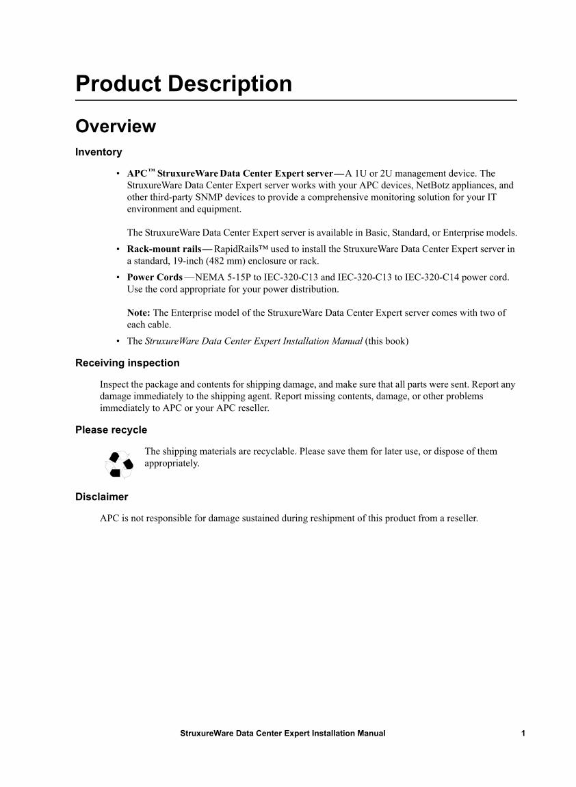
• APC™ StruxureWare Data Center Expert server—A 1U or 2U management device. The StruxureWare Data Center Expert server works with your APC devices, NetBotz appliances, and other third-party SNMP devices to provide a comprehensive monitoring solution for your IT environment and equipment.
The StruxureWare Data Center Expert server is available in Basic, Standard, or Enterprise models.• Rack-mount rails— RapidRails™ used to install the StruxureWare Data Center Expert server in
a standard, 19-inch (482 mm) enclosure or rack.• Power Cords —NEMA 5-15P to IEC-320-C13 and IEC-320-C13 to IEC-320-C14 power cord.
Use the cord appropriate for your power distribution.
Note: The Enterprise model of the StruxureWare Data Center Expert server comes with two of each cable.
• The StruxureWare Data Center Expert Installation Manual (this book)
Receiving inspection
Inspect the package and contents for shipping damage, and make sure that all parts were sent. Report any damage immediately to the shipping agent. Report missing contents, damage, or other problems immediately to APC or your APC reseller.
Please recycle
The shipping materials are recyclable. Please save them for later use, or dispose of them appropriately.
Disclaimer
APC is not responsible for damage sustained during reshipment of this product from a reseller.
1StruxureWare Data Center Expert Installation Manual
SafetyRack-mounting safety
The StruxureWare Data Center Expert server is shipped with rack-mounting rails. Install the rails at the appropriate position in your rack, and mount the unit. If the unit is mounted in an enclosure instead of an open rack, the maximum ambient temperature in the enclosure should be no greater than 35°C (95°F).
• When you install equipment in the rack, make sure it does not interfere with the air flow required for safe operation for the equipment.
• When you mount equipment in the rack, make sure you do not cause a hazardous condition because of an uneven mechanical load.
• When you connect equipment to the supply circuit, avoid overloading the circuits, which could jeopardize over-current protection and damage the supply wiring. See ratings on the equipment nameplates for guidance.
• Maintain reliable earth grounding of the unit, particularly for supply connections (e.g., when Power Distribution Units (PDUs) that are not directly connected to the branch circuit are used).
Equipment containing a battery
This equipment contains a non-replaceable lithium coin cell battery.
StruxureWare Data Center Expert Installation Manual2
Installation
Installation Instructions This installation guide provides instructions for trained service technicians installing one or more systems in a rack. The provided RapidRails rack kit can be installed without tools in any enclosure that has square holes. One rack kit is required for each system installed in the rack. VersaRails™ rack kits, which are designed for use with enclosures that have round holes, are available for purchase separately.
Caution: Do not install rack kit components designed for another system. Use only the rack kit for your system. Using the rack kit for another system may result in damage to the system and personal injury to yourself and to others.
Before You Begin Before you begin installing your system in the rack, read the safety instructions on page 2 and in this section.
Observe the following safety precautions when installing your system in the rack
Caution:
• When installing multiple systems in a rack, complete all of the procedures for the current system before attempting to install the next system. • Follow the procedures in this document to protect yourself as well as other service technicians. Your system is very large and heavy, and proper preparation and planning are important to prevent injury to yourself and to others, especially when systems are installed in the top half of the rack. • Installing systems in a rack without front and side stabilizer feet could cause the rack to tip over, potentially resulting in bodily injury. Always install the stabilizer feet of the rack before installing components. The stabilizer feet help prevent the rack from tipping over when a system or other component is pulled out of the rack with the slide assemblies fully extended. See the documentation provided with the rack cabinet for instructions on installing and anchoring the stabilizer feet. • After installing systems in a rack, never pull more than one system out of the rack on its slide assemblies at one time. The weight of more than one extended system could cause the rack to tip over and cause injury.
3StruxureWare Data Center Expert Installation Manual
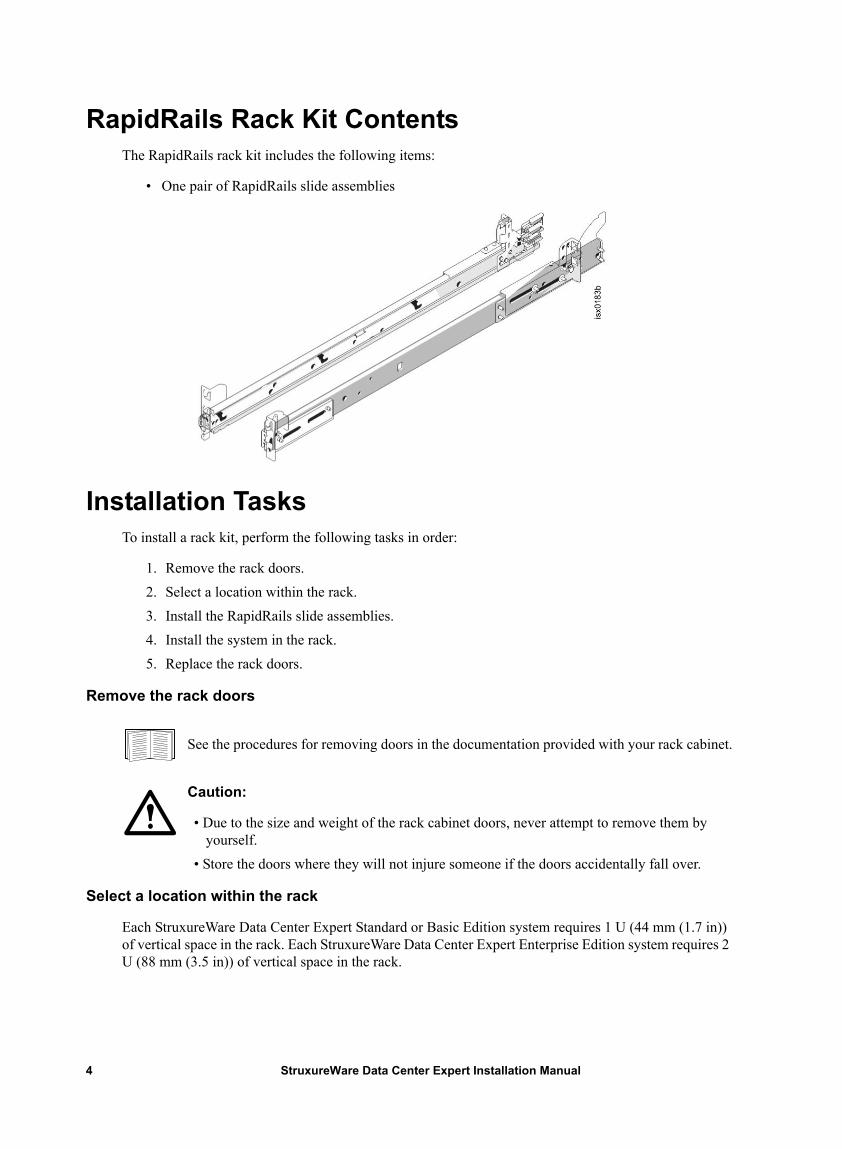
RapidRails Rack Kit Contents The RapidRails rack kit includes the following items:
• One pair of RapidRails slide assemblies
Installation Tasks To install a rack kit, perform the following tasks in order:
1. Remove the rack doors.2. Select a location within the rack.3. Install the RapidRails slide assemblies.4. Install the system in the rack.5. Replace the rack doors.
Remove the rack doors
See the procedures for removing doors in the documentation provided with your rack cabinet.
Caution:
• Due to the size and weight of the rack cabinet doors, never attempt to remove them by yourself.
• Store the doors where they will not injure someone if the doors accidentally fall over.
Select a location within the rack
Each StruxureWare Data Center Expert Standard or Basic Edition system requires 1 U (44 mm (1.7 in)) of vertical space in the rack. Each StruxureWare Data Center Expert Enterprise Edition system requires 2 U (88 mm (3.5 in)) of vertical space in the rack.
StruxureWare Data Center Expert Installation Manual4
Install the RapidRails slide assemblies
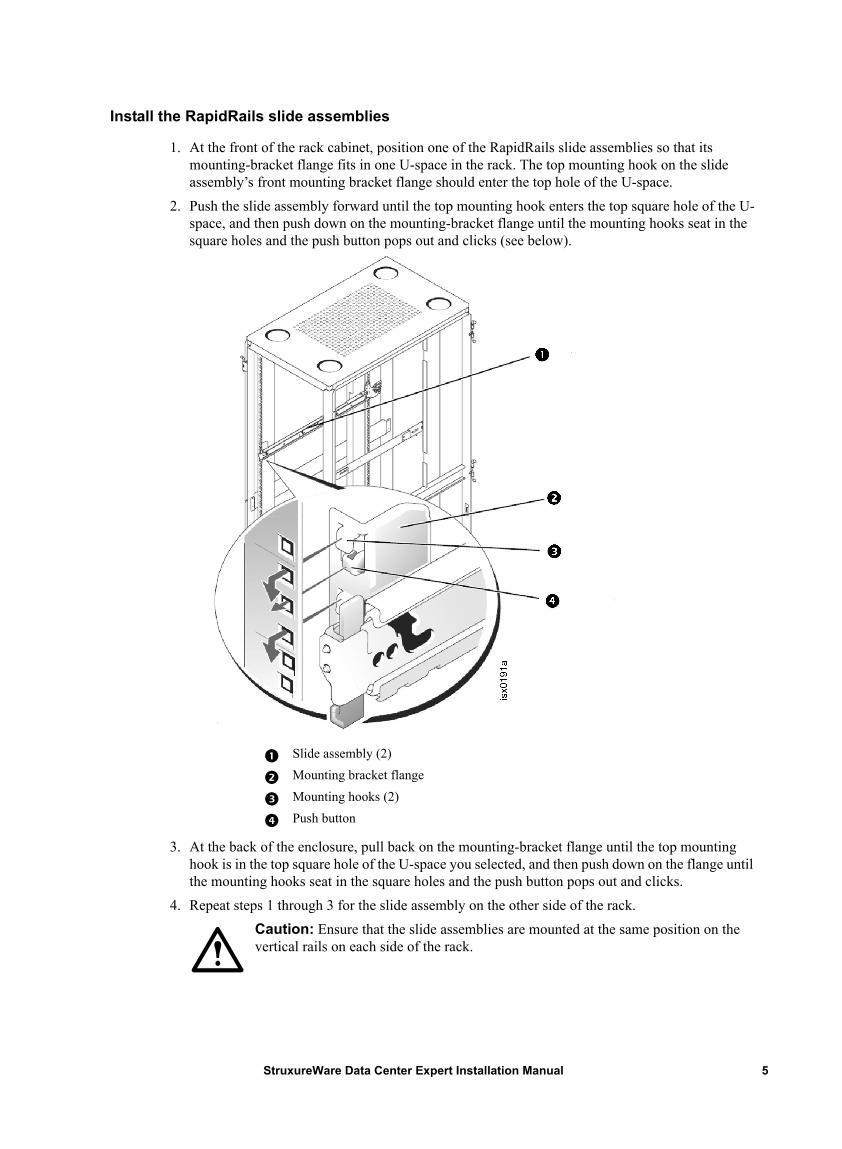
1. At the front of the rack cabinet, position one of the RapidRails slide assemblies so that its mounting-bracket flange fits in one U-space in the rack. The top mounting hook on the slide assembly’s front mounting bracket flange should enter the top hole of the U-space.
2. Push the slide assembly forward until the top mounting hook enters the top square hole of the U-space, and then push down on the mounting-bracket flange until the mounting hooks seat in the square holes and the push button pops out and clicks (see below).
3. At the back of the enclosure, pull back on the mounting-bracket flange until the top mounting hook is in the top square hole of the U-space you selected, and then push down on the flange until the mounting hooks seat in the square holes and the push button pops out and clicks.
4. Repeat steps 1 through 3 for the slide assembly on the other side of the rack. Caution: Ensure that the slide assemblies are mounted at the same position on the vertical rails on each side of the rack.
Slide assembly (2)Mounting bracket flangeMounting hooks (2)Push button
5StruxureWare Data Center Expert Installation Manual
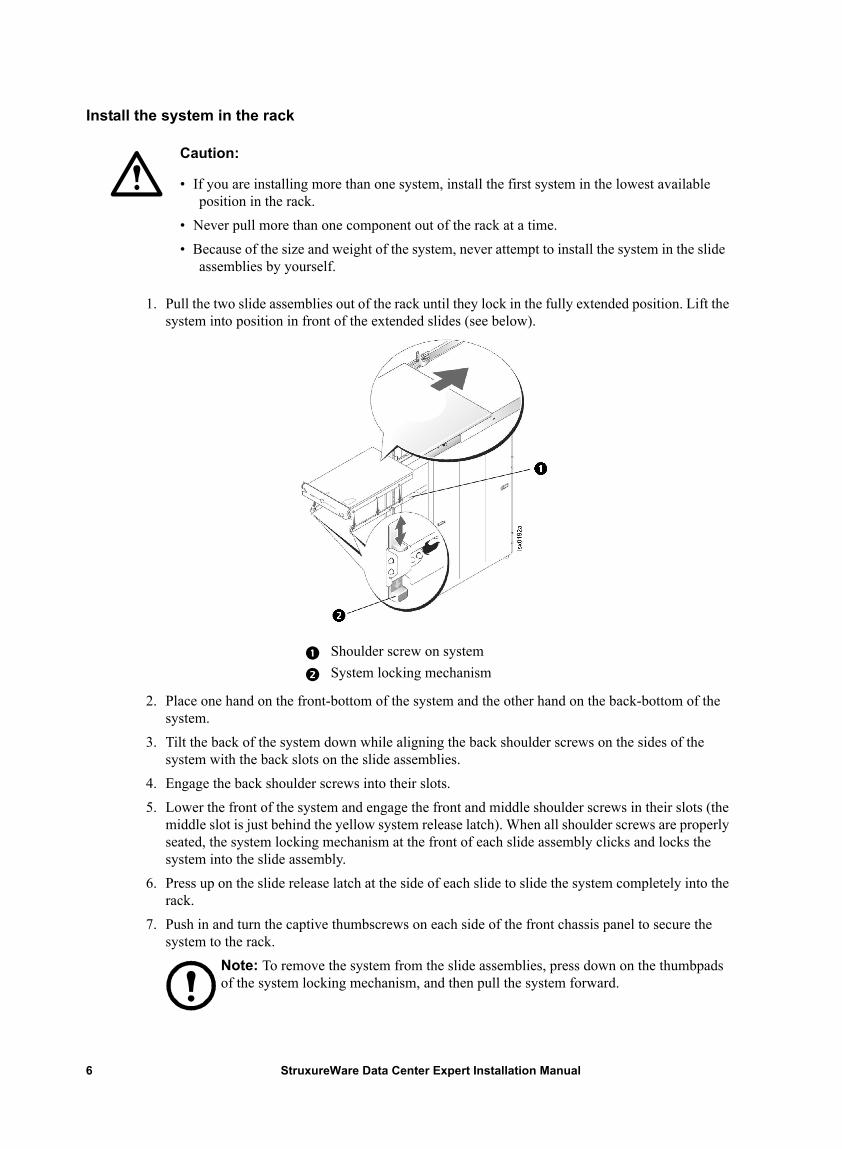
Install the system in the rack
1. Pull the two slide assemblies out of the rack until they lock in the fully extended position. Lift the system into position in front of the extended slides (see below).
2. Place one hand on the front-bottom of the system and the other hand on the back-bottom of the system.
3. Tilt the back of the system down while aligning the back shoulder screws on the sides of the system with the back slots on the slide assemblies.
4. Engage the back shoulder screws into their slots. 5. Lower the front of the system and engage the front and middle shoulder screws in their slots (the
middle slot is just behind the yellow system release latch). When all shoulder screws are properly seated, the system locking mechanism at the front of each slide assembly clicks and locks the system into the slide assembly.
6. Press up on the slide release latch at the side of each slide to slide the system completely into the rack.
7. Push in and turn the captive thumbscrews on each side of the front chassis panel to secure the system to the rack.
Note: To remove the system from the slide assemblies, press down on the thumbpads of the system locking mechanism, and then pull the system forward.
Caution:
• If you are installing more than one system, install the first system in the lowest available position in the rack.
• Never pull more than one component out of the rack at a time. • Because of the size and weight of the system, never attempt to install the system in the slide
assemblies by yourself.
Shoulder screw on systemSystem locking mechanism
StruxureWare Data Center Expert Installation Manual6
Replace the rack doors
See the procedures for replacing doors in the documentation provided with your rack.
Caution: Because of the size and weight of the rack cabinet doors, never attempt to remove or install them by yourself.
Communication ConnectionNetwork overview
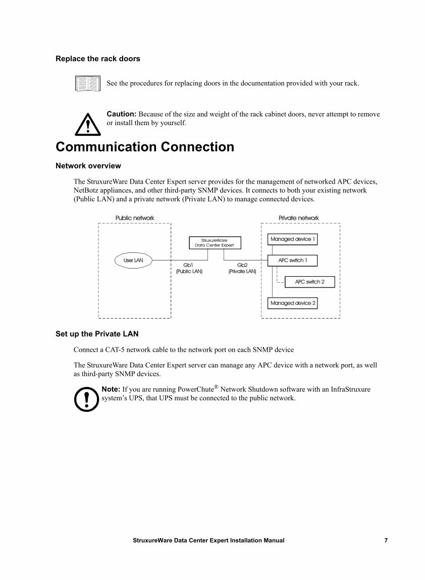
The StruxureWare Data Center Expert server provides for the management of networked APC devices, NetBotz appliances, and other third-party SNMP devices. It connects to both your existing network (Public LAN) and a private network (Private LAN) to manage connected devices.
Set up the Private LAN
Connect a CAT-5 network cable to the network port on each SNMP device
The StruxureWare Data Center Expert server can manage any APC device with a network port, as well as third-party SNMP devices.
Note: If you are running PowerChute® Network Shutdown software with an InfraStruxure system’s UPS, that UPS must be connected to the public network.
Gb2(Private LAN)
Managed device 2
User LAN Gb1 (Public LAN)
APC switch 1
Private networkPublic network
APC switch 2
Managed device 1
7StruxureWare Data Center Expert Installation Manual
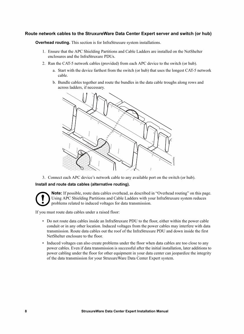
Route network cables to the StruxureWare Data Center Expert server and switch (or hub)
Overhead routing. This section is for InfraStruxure system installations.
1. Ensure that the APC Shielding Partitions and Cable Ladders are installed on the NetShelter enclosures and the InfraStruxure PDUs.
2. Run the CAT-5 network cables (provided) from each APC device to the switch (or hub).a. Start with the device farthest from the switch (or hub) that uses the longest CAT-5 network
cable. b. Bundle cables together and route the bundles in the data cable troughs along rows and
across ladders, if necessary.
3. Connect each APC device’s network cable to any available port on the switch (or hub). Install and route data cables (alternative routing).
Note: If possible, route data cables overhead, as described in “Overhead routing” on this page. Using APC Shielding Partitions and Cable Ladders with your InfraStruxure system reduces problems related to induced voltages for data transmission.
If you must route data cables under a raised floor:
• Do not route data cables inside an InfraStruxure PDU to the floor, either within the power cable conduit or in any other location. Induced voltages from the power cables may interfere with data transmission. Route data cables out the roof of the InfraStruxure PDU and down inside the first NetShelter enclosure to the floor.
• Induced voltages can also create problems under the floor when data cables are too close to any power cables. Even if data transmission is successful after the initial installation, later additions to power cabling under the floor for other equipment in your data center can jeopardize the integrity of the data transmission for your StruxureWare Data Center Expert system.
StruxureWare Data Center Expert Installation Manual8
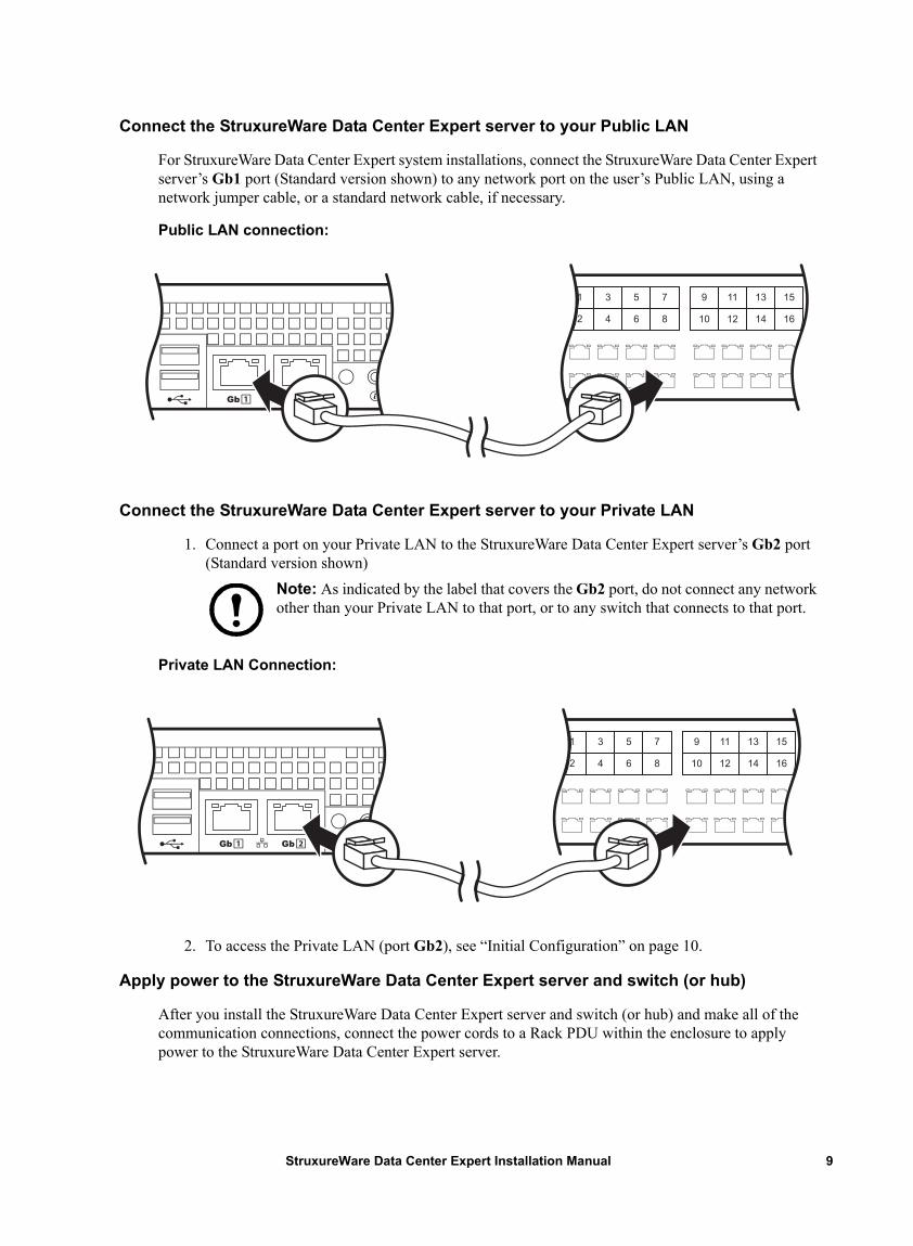
Connect the StruxureWare Data Center Expert server to your Public LAN
For StruxureWare Data Center Expert system installations, connect the StruxureWare Data Center Expert server’s Gb1 port (Standard version shown) to any network port on the user’s Public LAN, using a network jumper cable, or a standard network cable, if necessary.
Public LAN connection: .
Connect the StruxureWare Data Center Expert server to your Private LAN
1. Connect a port on your Private LAN to the StruxureWare Data Center Expert server’s Gb2 port (Standard version shown)
Note: As indicated by the label that covers the Gb2 port, do not connect any network other than your Private LAN to that port, or to any switch that connects to that port.
Private LAN Connection:
2. To access the Private LAN (port Gb2), see “Initial Configuration” on page 10.
Apply power to the StruxureWare Data Center Expert server and switch (or hub)
After you install the StruxureWare Data Center Expert server and switch (or hub) and make all of the communication connections, connect the power cords to a Rack PDU within the enclosure to apply power to the StruxureWare Data Center Expert server.
9StruxureWare Data Center Expert Installation Manual
Initial Configuration
Configure the StruxureWare Data Center Expert Server
To configure the public LAN network settings on the StruxureWare Data Center Expert server for the first time, you must connect to the StruxureWare Data Center Expert server as follows:
• Connect the private network port (Gb2) with a computer connected directly to the Gb2 port or connected to a switch (or hub) that is connected to the Gb2 port.
System and Web browser prerequisites
The StruxureWare Data Center Expert console is a stand-alone Java application that runs on systems that meet the following requirements:
• A PC with a 1 GHz or better AMD/Intel processor running Microsoft® Windows® (XP SP1, SP2, SP3; Server® 2003 SP2; Vista; or 7) or Red Hat® Enterprise Linux® 5.0 (32-bit platforms only)
• 1 GB RAM• A screen resolution of at least 1024x768• The browser must be JavaScript® enabled:
– Google Chrome™ version 23.0– Microsoft Internet Explorer® version 8, 9, 10– Mozilla Firefox® version 17.0
Configuring the StruxureWare Data Center Expert server from a remote computer
1. Connect a computer to a network port on the private switch (or hub), or directly to the Gb2 port if a switch (or hub) is unavailable. The computer must meet the following requirements:– It must be configured to obtain an IP address automatically (through DHCP).
– It must be running TCP/IP as a network protocol.2. Release and renew your computer’s IP address to assign it an address on the Private LAN.3. Open the browser, and enter the LAN IP address for the StruxureWare Data Center Expert server.4. Use 192.168.1.1 as the default IP address for StruxureWare Data Center Expert on the LAN.5. Log in to the StruxureWare Data Center Expert Web Client, using apc (lowercase) for both the
username and password. Click Download Client in the upper right corner to download and install the StruxureWare Data Center Expert client.
6. Double-click the StruxureWare Data Center Expert icon to display the StruxureWare Data Center Expert Logon dialog, and log in using apc (lowercase) for both the username and password.
7. In the System menu, select Server Administration Settings, then select Network Settings.8. On the Public tab of the Network Settings display, enter the necessary information about the
StruxureWare Data Center Expert server. This information can be provided by your network administrator.
9. When you are finished, click Apply and then OK.
StruxureWare Data Center Expert Installation Manual10
Enable Remote MonitoringAPC can remotely monitor your StruxureWare Data Center Expert server and the devices it manages, and notify you of events via e-mail, pager, or phone. If you decide to use APC’s Remote Monitoring Service (RMS), follow these steps:.
1. From the Alarm Configuration menu, select Remote Monitoring Service.2. In the APC Remote Monitoring Service display, click Registration Settings.3. If you have not registered for RMS:
a. In the Choose RMS Settings Type display, select New Customer and click Next.b. In the RMS Contact Information display, fill in all of the required fields and click Next. c. In the RMS Company Information display, fill in all of the required fields and click
Finish.
4. If you have previously registered for RMS:a. In the Choose RMS Settings Type display, select Existing Customer and click Next.b. In the RMS Logon Settings display, fill in your e-mail address and password, then click
Next. c. In the RMS Contact Information display, verify that the displayed information is correct
and click Next. d. In the RMS Company Information display, verify that the information is correct and click
Finish.
5. Visit http://rms.apc.com to complete the RMS configuration. On the RMS page, click Contact Us to obtain the phone number to call and complete the activation process.
Warning: Information that will be sent to the APC monitoring service must be entered in English. Any other language may prevent RMS from being able to properly notify of or describe any critical issues.
11StruxureWare Data Center Expert Installation Manual
Product Information
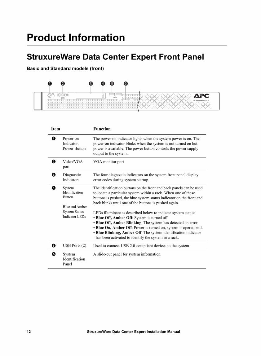
StruxureWare Data Center Expert Front PanelBasic and Standard models (front)
Item Function
Power-on Indicator, Power Button
The power-on indicator lights when the system power is on. The power-on indicator blinks when the system is not turned on but power is available. The power button controls the power supply output to the system.
Video/VGA port
VGA monitor port
Diagnostic Indicators
The four diagnostic indicators on the system front panel display error codes during system startup.
System Identification Button
Blue and Amber System Status Indicator LEDs
The identification buttons on the front and back panels can be used to locate a particular system within a rack. When one of these buttons is pushed, the blue system status indicator on the front and back blinks until one of the buttons is pushed again.
LEDs illuminate as described below to indicate system status:• Blue Off, Amber Off: System is turned off.• Blue Off, Amber Blinking: The system has detected an error.• Blue On, Amber Off: Power is turned on, system is operational.• Blue Blinking, Amber Off: The system identification indicator
has been activated to identify the system in a rack.
USB Ports (2) Used to connect USB 2.0-compliant devices to the system
System Identification Panel
A slide-out panel for system information
StruxureWare Data Center Expert Installation Manual12
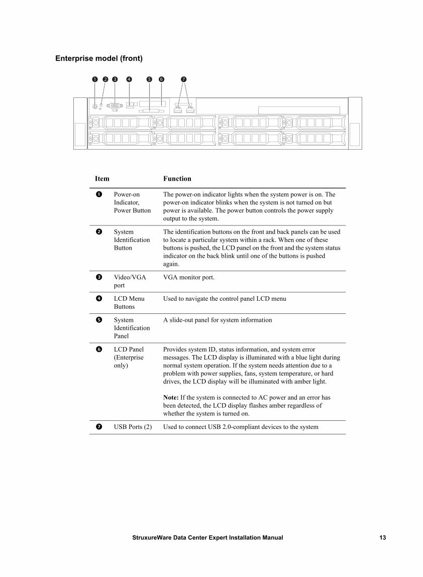
Enterprise model (front)
Item Function
Power-on Indicator, Power Button
The power-on indicator lights when the system power is on. The power-on indicator blinks when the system is not turned on but power is available. The power button controls the power supply output to the system.
System Identification Button
The identification buttons on the front and back panels can be used to locate a particular system within a rack. When one of these buttons is pushed, the LCD panel on the front and the system status indicator on the back blink until one of the buttons is pushed again.
Video/VGA port
VGA monitor port.
LCD Menu Buttons
Used to navigate the control panel LCD menu
System Identification Panel
A slide-out panel for system information
LCD Panel (Enterprise only)
Provides system ID, status information, and system error messages. The LCD display is illuminated with a blue light during normal system operation. If the system needs attention due to a problem with power supplies, fans, system temperature, or hard drives, the LCD display will be illuminated with amber light.
Note: If the system is connected to AC power and an error has been detected, the LCD display flashes amber regardless of whether the system is turned on.
USB Ports (2) Used to connect USB 2.0-compliant devices to the system
13StruxureWare Data Center Expert Installation Manual
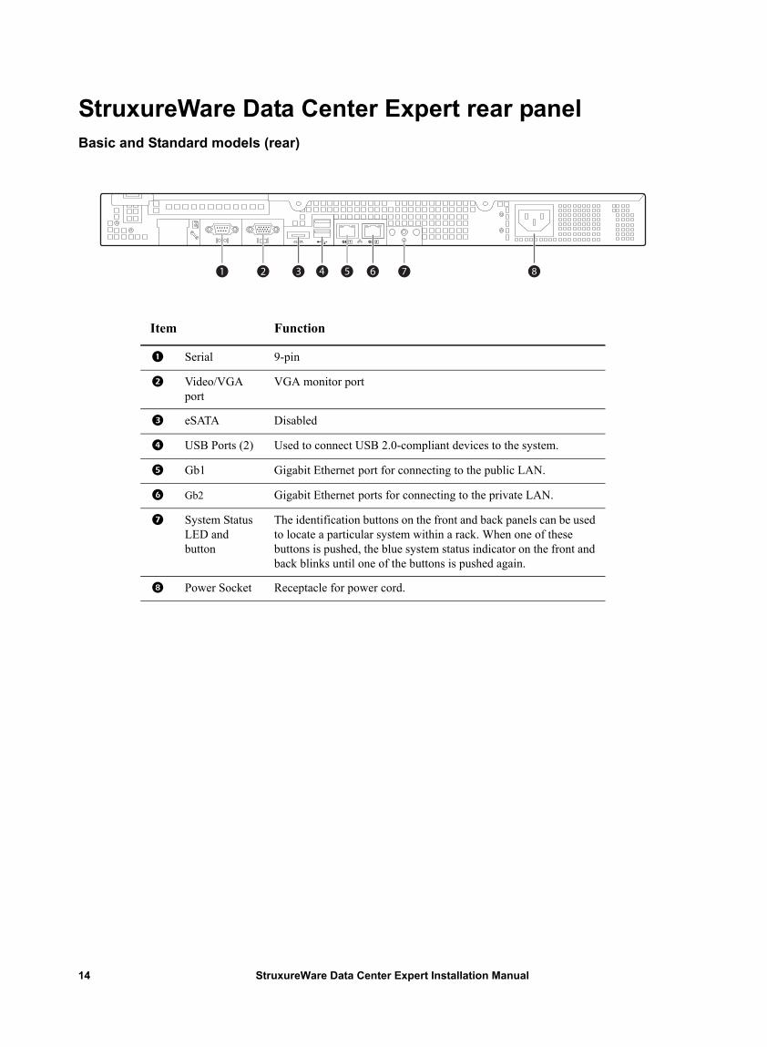
StruxureWare Data Center Expert rear panelBasic and Standard models (rear)
Item Function
Serial 9-pin
Video/VGA port
VGA monitor port
eSATA Disabled
USB Ports (2) Used to connect USB 2.0-compliant devices to the system.
Gb1 Gigabit Ethernet port for connecting to the public LAN.
Gb2 Gigabit Ethernet ports for connecting to the private LAN.
System Status LED and button
The identification buttons on the front and back panels can be used to locate a particular system within a rack. When one of these buttons is pushed, the blue system status indicator on the front and back blinks until one of the buttons is pushed again.
Power Socket Receptacle for power cord.
StruxureWare Data Center Expert Installation Manual14
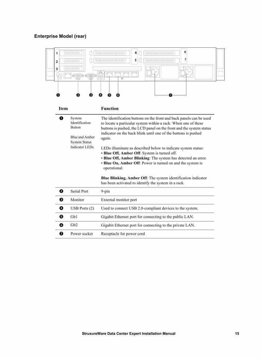
Enterprise Model (rear)
Item Function
System Identification Button
Blue and Amber System Status Indicator LEDs
The identification buttons on the front and back panels can be used to locate a particular system within a rack. When one of these buttons is pushed, the LCD panel on the front and the system status indicator on the back blink until one of the buttons is pushed again.
LEDs illuminate as described below to indicate system status:• Blue Off, Amber Off: System is turned off.• Blue Off, Amber Blinking: The system has detected an error.• Blue On, Amber Off: Power is turned on and the system is
operational.
Blue Blinking, Amber Off: The system identification indicator has been activated to identify the system in a rack.
Serial Port 9-pin
Monitor External monitor port
USB Ports (2) Used to connect USB 2.0-compliant devices to the system.
Gb1 Gigabit Ethernet port for connecting to the public LAN.
Gb2 Gigabit Ethernet port for connecting to the private LAN.
Power socket Receptacle for power cord
15StruxureWare Data Center Expert Installation Manual
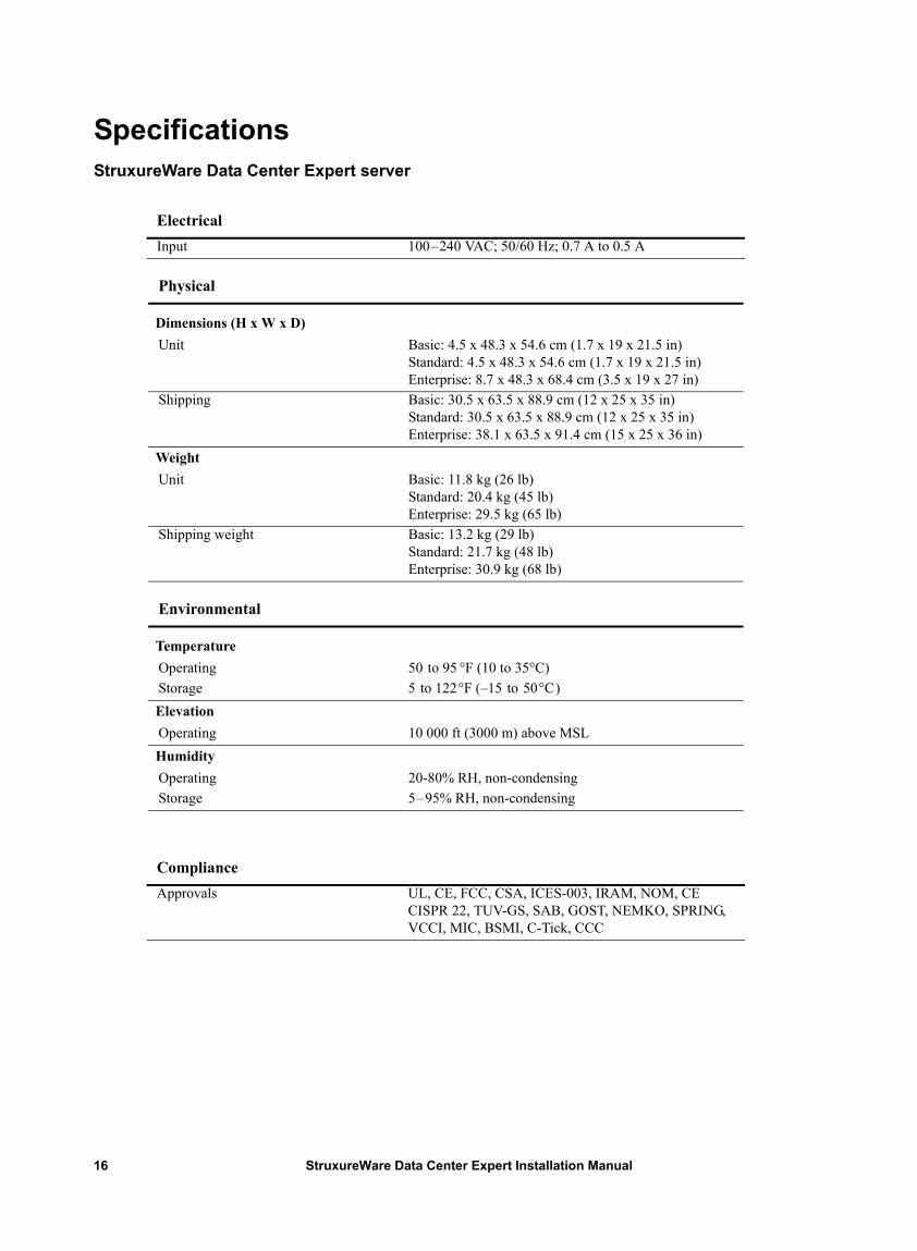
SpecificationsStruxureWare Data Center Expert server
Electrical Input 100–240 VAC; 50/60 Hz; 0.7 A to 0.5 A
Physical
Dimensions (H x W x D)Unit Basic: 4.5 x 48.3 x 54.6 cm (1.7 x 19 x 21.5 in)
Standard: 4.5 x 48.3 x 54.6 cm (1.7 x 19 x 21.5 in)Enterprise: 8.7 x 48.3 x 68.4 cm (3.5 x 19 x 27 in)
Shipping Basic: 30.5 x 63.5 x 88.9 cm (12 x 25 x 35 in)Standard: 30.5 x 63.5 x 88.9 cm (12 x 25 x 35 in)Enterprise: 38.1 x 63.5 x 91.4 cm (15 x 25 x 36 in)
WeightUnit Basic: 11.8 kg (26 lb)
Standard: 20.4 kg (45 lb)Enterprise: 29.5 kg (65 lb)
Shipping weight Basic: 13.2 kg (29 lb)Standard: 21.7 kg (48 lb)Enterprise: 30.9 kg (68 lb)
Environmental
TemperatureOperating 50 to 95 °F (10 to 35°C)Storage 5 to 122°F (–15 to 50°C)ElevationOperating 10 000 ft (3000 m) above MSLHumidityOperating 20-80% RH, non-condensingStorage 5–95% RH, non-condensing
Compliance Approvals UL, CE, FCC, CSA, ICES-003, IRAM, NOM, CE
CISPR 22, TUV-GS, SAB, GOST, NEMKO, SPRING, VCCI, MIC, BSMI, C-Tick, CCC
StruxureWare Data Center Expert Installation Manual16
Warranties and Policies
Two-Year Factory WarrantyThis warranty applies only to the products you purchase for your use in accordance with this manual.
Terms of warranty
APC warrants its products to be free from defects in materials and workmanship for a period of two years from the date of purchase. APC will repair or replace defective products covered by this warranty. This warranty does not apply to equipment that has been damaged by accident, negligence or misapplication or has been altered or modified in any way. Repair or replacement of a defective product or part thereof does not extend the original warranty period. Any parts furnished under this warranty may be new or factory-remanufactured.
Non-transferable warranty
This warranty extends only to the original purchaser who must have properly registered the product. The product may be registered at the APC Web site, www.apc.com.
Exclusions
APC shall not be liable under the warranty if its testing and examination disclose that the alleged defect in the product does not exist or was caused by end user’s or any third person’s misuse, negligence, improper installation or testing. Further, APC shall not be liable under the warranty for unauthorized attempts to repair or modify wrong or inadequate electrical voltage or connection, inappropriate on-site operation conditions, corrosive atmosphere, repair, installation, exposure to the elements, Acts of God, fire, theft, or installation contrary to APC recommendations or specifications or in any event if the APC serial number has been altered, defaced, or removed, or any other cause beyond the range of the intended use.
THERE ARE NO WARRANTIES, EXPRESS OR IMPLIED, BY OPERATION OF LAW OR OTHERWISE, OF PRODUCTS SOLD, SERVICED OR FURNISHED UNDER THIS AGREEMENT OR IN CONNECTION HEREWITH. APC DISCLAIMS ALL IMPLIED WARRANTIES OF MERCHANTABILITY, SATISFACTION AND FITNESS FOR A PARTICULAR PURPOSE. APC EXPRESS WARRANTIES WILL NOT BE ENLARGED, DIMINISHED, OR AFFECTED BY AND NO OBLIGATION OR LIABILITY WILL ARISE OUT OF, APC RENDERING OF TECHNICAL OR OTHER ADVICE OR SERVICE IN CONNECTION WITH THE PRODUCTS. THE FOREGOING WARRANTIES AND REMEDIES ARE EXCLUSIVE AND IN LIEU OF ALL OTHER WARRANTIES AND REMEDIES. THE WARRANTIES SET FORTH ABOVE CONSTITUTE APC’S SOLE LIABILITY AND PURCHASER’S EXCLUSIVE REMEDY FOR ANY BREACH OF SUCH WARRANTIES. APC WARRANTIES EXTEND ONLY TO PURCHASER AND ARE NOT EXTENDED TO ANY THIRD PARTIES.
17StruxureWare Data Center Expert Installation Manual
IN NO EVENT SHALL APC, ITS OFFICERS, DIRECTORS, AFFILIATES OR EMPLOYEES BE LIABLE FOR ANY FORM OF INDIRECT, SPECIAL, CONSEQUENTIAL OR PUNITIVE DAMAGES, ARISING OUT OF THE USE, SERVICE OR INSTALLATION, OF THE PRODUCTS, WHETHER SUCH DAMAGES ARISE IN CONTRACT OR TORT, IRRESPECTIVE OF FAULT, NEGLIGENCE OR STRICT LIABILITY OR WHETHER APC HAS BEEN ADVISED IN ADVANCE OF THE POSSIBILITY OF SUCH DAMAGES. SPECIFICALLY, APC IS NOT LIABLE FOR ANY COSTS, SUCH AS LOST PROFITS OR REVENUE, LOSS OF EQUIPMENT, LOSS OF USE OF EQUIPMENT, LOSS OF SOFTWARE, LOSS OF DATA, COSTS OF SUBSTITUENTS, CLAIMS BY THIRD PARTIES, OR OTHERWISE.
NO SALESMAN, EMPLOYEE OR AGENT OF APC IS AUTHORIZED TO ADD TO OR VARY THE TERMS OF THIS WARRANTY. WARRANTY TERMS MAY BE MODIFIED, IF AT ALL, ONLY IN WRITING SIGNED BY AN APC OFFICER AND LEGAL DEPARTMENT.
Warranty claims
Customers with warranty claims issues may access the APC customer support network through the Support page of the APC Web site, www.apc.com/support. Select your country from the country selection pull-down menu at the top of the Web page. Select the Support tab to obtain contact information for customer support in your region.
StruxureWare Data Center Expert Installation Manual18

01/2013990-3321E-001
APC Worldwide Customer SupportCustomer support for this or any other APC product is available in any of the following ways:
• Visit the APC Web site to access documents in the APC Knowledge Base and to submit customer support requests.– www.apc.com (Corporate Headquarters)
Connect to localized APC Web sites for specific countries, each of which provides customer support information.
– www.apc.com/support/Global support searching APC Knowledge Base and using e-support.
• Contact the APC Customer Support Center by telephone or e-mail.– Local, country-specific centers: go to www.apc.com/support/contact for contact information.
For information on how to obtain local customer support, contact the APC representative or other distributors from whom you purchased your APC product.
© 2013 APC by Schneider Electric. APC, the APC logo, NetShelter, PowerChute, and InfraStruxure are owned by Schneider Electric Industries S.A.S., American Power Conversion Corporation, or their affiliated
companies. All other trademarks are property of their respective owners.