Embed Size (px)
Citation preview
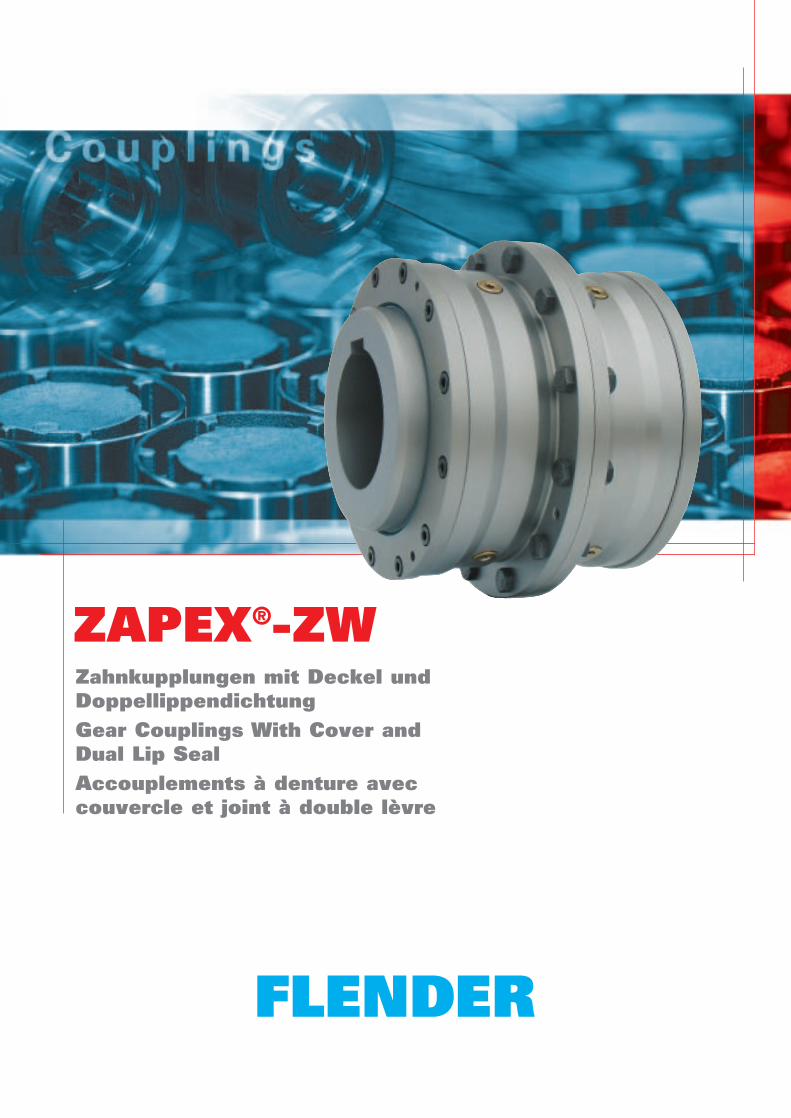
ZAPEX®-ZWZahnkupplungen mit Deckel und DoppellippendichtungGear Couplings With Cover and Dual Lip SealAccouplements à denture avec couvercle et joint à double lèvre
K432 DE/EN/FR2
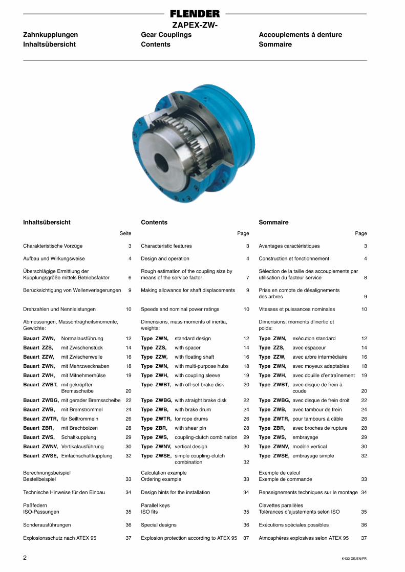
ZAPEX-ZW-Zahnkupplungen Gear Couplings Accouplements à dentureInhaltsübersicht Contents Sommaire
Inhaltsübersicht
Seite
Charakteristische Vorzüge 3
Aufbau und Wirkungsweise 4
Überschlägige Ermittlung derKupplungsgröße mittels Betriebsfaktor 6
Berücksichtigung von Wellenverlagerungen 9
Drehzahlen und Nennleistungen 10
Abmessungen, Massenträgheitsmomente,Gewichte:
Bauart ZWN, Normalausführung 12
Bauart ZZS, mit Zwischenstück 14
Bauart ZZW, mit Zwischenwelle 16
Bauart ZWN, mit Mehrzwecknaben 18
Bauart ZWH, mit Mitnehmerhülse 19
Bauart ZWBT, mit gekröpfterBremsscheibe 20
Bauart ZWBG, mit gerader Bremsscheibe 22
Bauart ZWB, mit Bremstrommel 24
Bauart ZWTR, für Seiltrommeln 26
Bauart ZBR, mit Brechbolzen 28
Bauart ZWS, Schaltkupplung 29
Bauart ZWNV, Vertikalausführung 30
Bauart ZWSE, Einfachschaltkupplung 32
BerechnungsbeispielBestellbeispiel 33
Technische Hinweise für den Einbau 34
PaßfedernISO-Passungen 35
Sonderausführungen 36
Explosionsschutz nach ATEX 95 37
Contents
Page
Characteristic features 3
Design and operation 4
Rough estimation of the coupling size bymeans of the service factor 7
Making allowance for shaft displacements 9
Speeds and nominal power ratings 10
Dimensions, mass moments of inertia,weights:
Type ZWN, standard design 12
Type ZZS, with spacer 14
Type ZZW, with floating shaft 16
Type ZWN, with multi-purpose hubs 18
Type ZWH, with coupling sleeve 19
Type ZWBT, with off-set brake disk 20
Type ZWBG, with straight brake disk 22
Type ZWB, with brake drum 24
Type ZWTR, for rope drums 26
Type ZBR, with shear pin 28
Type ZWS, coupling-clutch combination 29
Type ZWNV, vertical design 30
Type ZWSE, simple coupling-clutch combination 32
Calculation exampleOrdering example 33
Design hints for the installation 34
Parallel keysISO fits 35
Special designs 36
Explosion protection according to ATEX 95 37
Sommaire
Page
Avantages caractéristiques 3
Construction et fonctionnement 4
Sélection de la taille des accouplements parutilisation du facteur service 8
Prise en compte de désalignementsdes arbres 9
Vitesses et puissances nominales 10
Dimensions, moments d’inertie etpoids:
Type ZWN, exécution standard 12
Type ZZS, avec espaceur 14
Type ZZW, avec arbre intermédiaire 16
Type ZWN, avec moyeux adaptables 18
Type ZWH, avec douille d’entraînement 19
Type ZWBT, avec disque de frein àcoude 20
Type ZWBG, avec disque de frein droit 22
Type ZWB, avec tambour de frein 24
Type ZWTR, pour tambours à câble 26
Type ZBR, avec broches de rupture 28
Type ZWS, embrayage 29
Type ZWNV, modèle vertical 30
Type ZWSE, embrayage simple 32
Exemple de calculExemple de commande 33
Renseignements techniques sur le montage 34
Clavettes parallèlesTolérances d’ajustements selon ISO 35
Exécutions spéciales possibles 36
Atmosphères explosives selon ATEX 95 37
K432 DE/EN/FR 3
ZAPEX-ZW-Zahnkupplungen Gear Couplings Accouplements à dentureCharakteristische Vorzüge Characteristic Features Avantages caractéristiques
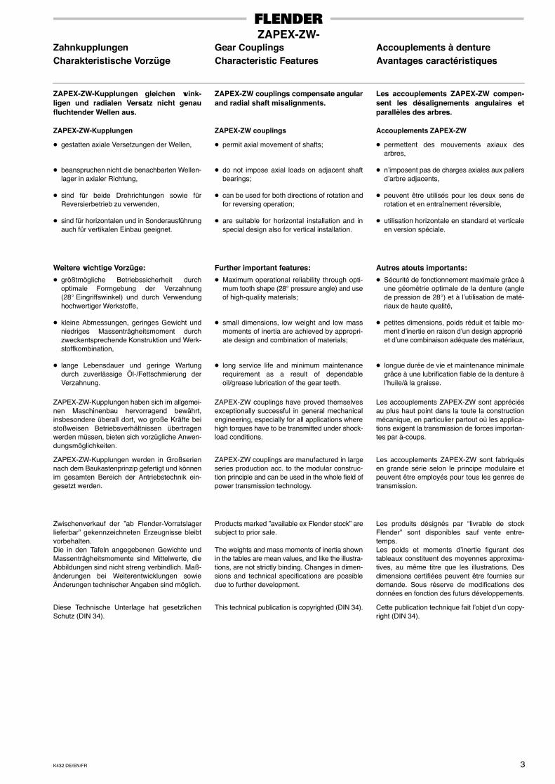
ZAPEX-ZW-Kupplungen gleichen wink-ligen und radialen Versatz nicht genaufluchtender Wellen aus.
ZAPEX-ZW-Kupplungen
� gestatten axiale Versetzungen der Wellen,
� beanspruchen nicht die benachbarten Wellen-lager in axialer Richtung,
� sind für beide Drehrichtungen sowie fürReversierbetrieb zu verwenden,
� sind für horizontalen und in Sonderausführungauch für vertikalen Einbau geeignet.
Weitere wichtige Vorzüge:
� größtmögliche Betriebssicherheit durchoptimale Formgebung der Verzahnung(28° Eingriffswinkel) und durch Verwendunghochwertiger Werkstoffe,
� kleine Abmessungen, geringes Gewicht undniedriges Massenträgheitsmoment durchzweckentsprechende Konstruktion und Werk-stoffkombination,
� lange Lebensdauer und geringe Wartungdurch zuverlässige Öl-/Fettschmierung derVerzahnung.
ZAPEX-ZW-Kupplungen haben sich im allgemei-nen Maschinenbau hervorragend bewährt,insbesondere überall dort, wo große Kräfte beistoßweisen Betriebsverhältnissen übertragenwerden müssen, bieten sich vorzügliche Anwen-dungsmöglichkeiten.
ZAPEX-ZW-Kupplungen werden in Großseriennach dem Baukastenprinzip gefertigt und könnenim gesamten Bereich der Antriebstechnik ein-gesetzt werden.
Zwischenverkauf der ”ab Flender-Vorratslagerlieferbar” gekennzeichneten Erzeugnisse bleibtvorbehalten.Die in den Tafeln angegebenen Gewichte undMassenträgheitsmomente sind Mittelwerte, dieAbbildungen sind nicht streng verbindlich. Maß-änderungen bei Weiterentwicklungen sowieÄnderungen technischer Angaben sind möglich.
Diese Technische Unterlage hat gesetzlichenSchutz (DIN 34).
ZAPEX-ZW couplings compensate angularand radial shaft misalignments.
ZAPEX-ZW couplings
� permit axial movement of shafts;
� do not impose axial loads on adjacent shaftbearings;
� can be used for both directions of rotation andfor reversing operation;
� are suitable for horizontal installation and inspecial design also for vertical installation.
Further important features:
� Maximum operational reliability through opti-mum tooth shape (28° pressure angle) and useof high-quality materials;
� small dimensions, low weight and low massmoments of inertia are achieved by appropri-ate design and combination of materials;
� long service life and minimum maintenancerequirement as a result of dependableoil/grease lubrication of the gear teeth.
ZAPEX-ZW couplings have proved themselvesexceptionally successful in general mechanicalengineering, especially for all applications wherehigh torques have to be transmitted under shock-load conditions.
ZAPEX-ZW couplings are manufactured in largeseries production acc. to the modular construc-tion principle and can be used in the whole field ofpower transmission technology.
Products marked ”available ex Flender stock” aresubject to prior sale.
The weights and mass moments of inertia shownin the tables are mean values, and like the illustra-tions, are not strictly binding. Changes in dimen-sions and technical specifications are possibledue to further development.
This technical publication is copyrighted (DIN 34).
Les accouplements ZAPEX-ZW compen-sent les désalignements angulaires etparallèles des arbres.
Accouplements ZAPEX-ZW
� permettent des mouvements axiaux desarbres,
� n’imposent pas de charges axiales aux paliersd’arbre adjacents,
� peuvent être utilisés pour les deux sens derotation et en entraînement réversible,
� utilisation horizontale en standard et verticaleen version spéciale.
Autres atouts importants:
� Sécurité de fonctionnement maximale grâce àune géométrie optimale de la denture (anglede pression de 28°) et à l’utilisation de maté-riaux de haute qualité,
� petites dimensions, poids réduit et faible mo-ment d’inertie en raison d’un design approprié et d’une combinaison adéquate des matériaux,
� longue durée de vie et maintenance minimalegrâce à une lubrification fiable de la denture àl’huile/à la graisse.
Les accouplements ZAPEX-ZW sont appréciésau plus haut point dans la toute la constructionmécanique, en particulier partout où les applica-tions exigent la transmission de forces importan-tes par à-coups.
Les accouplements ZAPEX-ZW sont fabriquésen grande série selon le principe modulaire etpeuvent être employés pour tous les genres detransmission.
Les produits désignés par “livrable de stockFlender” sont disponibles sauf vente entre-temps.Les poids et moments d’inertie figurant destableaux constituent des moyennes approxima-tives, au même titre que les illustrations. Desdimensions certifiées peuvent être fournies surdemande. Sous réserve de modifications desdonnées en fonction des futurs développements.
Cette publication technique fait l’objet d’un copy-right (DIN 34).
K432 DE/EN/FR4
ZAPEX-ZW-Zahnkupplungen Gear Couplings Accouplements à dentureAufbau und Wirkungsweise Design and Operation Construction et fonctionnement
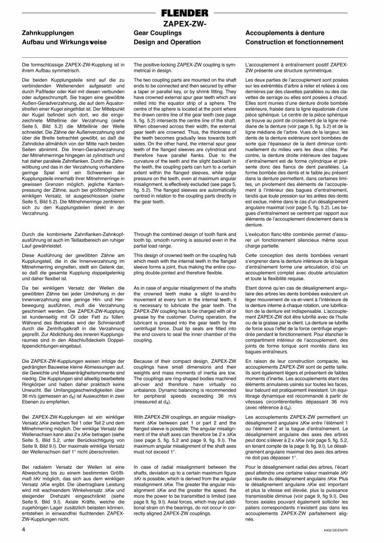
Die formschlüssige ZAPEX-ZW-Kupplung ist inihrem Aufbau symmetrisch.
Die beiden Kupplungsteile sind auf die zuverbindenden Wellenenden aufgesetzt unddurch Paßfeder oder Keil mit diesen verbundenoder aufgeschrumpft. Sie tragen eine gewölbteAußen-Geradverzahnung, die auf dem Äquator-streifen einer Kugel eingefräst ist. Der Mittelpunktder Kugel befindet sich dort, wo die einge-zeichnete Mittellinie der Verzahnung (sieheSeite 5, Bild 5.2) die Mittellinie der Welleschneidet. Die Zähne der Außenverzahnung sindüber die Breite betrachtet gewölbt, so daß dieZahndicke allmählich von der Mitte nach beidenSeiten abnimmt. Die Innen-Geradverzahnungder Mitnehmerringe hingegen ist zylindrisch undhat daher parallele Zahnflanken. Durch die Zahn-wölbung und das in der Verzahnung vorhandenegeringe Spiel wird ein Schwenken derKupplungsteile innerhalb ihrer Mitnehmerringe ingewissen Grenzen möglich, jegliche Kanten-pressung der Zähne, auch bei größtmöglichemwinkligen Versatz, ist ausgeschlossen (sieheSeite 5, Bild 5.2). Die Mitnehmerringe zentrierensich zu den Kupplungsteilen direkt in derVerzahnung.
Durch die kombinierte Zahnflanken-Zahnkopf-ausführung ist auch im Teillastbereich ein ruhigerLauf gewährleistet.
Diese Ausführung der gewölbten Zähne amKupplungsteil, die in die Innenverzahnung imMitnehmerring eingreifen, stellt ein Gelenk dar,so daß die gesamte Kupplung doppelgelenkigund daher flexibel ist.
Da bei winkligem Versatz der Wellen diegewölbten Zähne bei jeder Umdrehung in derInnenverzahnung eine geringe Hin- und Her-bewegung ausführen, muß die Verzahnunggeschmiert werden. Die ZAPEX-ZW-Kupplungist kundenseitig mit Öl oder Fett zu füllen.Während des Betriebes wird der Schmierstoffdurch die Zentrifugalkraft in die Verzahnunggepreßt. Zur Abdichtung des inneren Kupplungs-raumes sind in den Abschlußdeckeln Doppel-lippendichtungen eingebaut.
Die ZAPEX-ZW-Kupplungen weisen infolge dergedrängten Bauweise kleine Abmessungen auf,die Gewichte und Massenträgheitsmomente sindniedrig. Die Kupplungen sind allseitig bearbeiteteRingkörper und haben daher praktisch keineUnwucht. Bei Umfangsgeschwindigkeiten über36 m/s (gemessen an d4) ist Auswuchten in zweiEbenen zu empfehlen.
Bei ZAPEX-ZW-Kupplungen ist ein winkligerVersatz ∆Kw zwischen Teil 1 oder Teil 2 und demMitnehmerring möglich. Der winklige Versatz derWellenachsen kann also 2 x ∆Kw betragen (sieheSeite 5, Bild 5.2, unter Berücksichtigung vonSeite 9, Bild 9.I). Der maximale winklige Versatzder Wellenachsen darf 1° nicht überschreiten.
Bei radialem Versatz der Wellen ist eineAbweichung bis zu einem bestimmten Größt-maß ∆Kr möglich, das sich aus dem winkligenVersatz ∆Kw ergibt. Die übertragbare Leistungwird mit wachsendem Winkelversatz ∆Kw undsteigender Drehzahl eingeschränkt (sieheSeite 9, Bild 9.I). Axiale Kräfte, welche diezugehörigen Lager zusätzlich belasten können,entstehen in einwandfrei fluchtenden ZAPEX-ZW-Kupplungen nicht.
The positive-locking ZAPEX-ZW coupling is sym-metrical in design.
The two coupling parts are mounted on the shaftends to be connected and then secured by eithera taper or parallel key, or by shrink fitting. Theyhave crowned external spur gear teeth which aremilled into the equator strip of a sphere. Thecentre of the sphere is located at the point wherethe drawn centre line of the gear teeth (see page5, fig. 5.2) intersects the centre line of the shaft.When observed across their width, the externalgear teeth are crowned. Thus, the thickness ofthe teeth becomes gradually less towards bothsides. On the other hand, the internal spur gearteeth of the flanged sleeves are cylindrical andtherefore have parallel flanks. Due to thecurvature of the teeth and the slight backlash inthe teeth, the coupling parts can turn to a certainextent within the flanged sleeves, while edgepressure on the teeth, even at maximum angularmisalignment, is effectively excluded (see page 5,fig. 5.2). The flanged sleeves are automaticallycentred in relation to the coupling parts directly inthe gear teeth.
Through the combined design of tooth flank andtooth tip, smooth running is assured even in thepartial load range.
This design of crowned teeth on the coupling hubwhich mesh with the internal teeth in the flangedsleeve forms a joint, thus making the entire cou-pling double-jointed and therefore flexible.
As in case of angular misalignment of the shaftsthe crowned teeth make a slight to-and-fromovement at every turn in the internal teeth, itis necessary to lubricate the gear teeth. TheZAPEX-ZW coupling has to be charged with oil orgrease by the customer. During operation, thelubricant is pressed into the gear teeth by thecentrifugal force. Dual lip seals are fitted intothe end covers to seal the inner chamber of thecoupling.
Because of their compact design, ZAPEX-ZWcouplings have small dimensions and theirweights and mass moments of inertia are low.The couplings are ring-shaped bodies machinedall-over and therefore have virtually nounbalance. Dynamic balancing is recommendedfor peripheral speeds exceeding 36 m/s(measured at d4).
With ZAPEX-ZW couplings, an angular misalign-ment ∆Kw between part 1 or part 2 and theflanged sleeve is possible. The angular misalign-ment of the shaft axes can therefore be 2 x ∆Kw(see page 5, fig. 5.2 and page 9, fig. 9.I). Themaximum angular misalignment of the shaft axesmust not exceed 1°.
In case of radial misalignment between theshafts, deviation up to a certain maximum figure∆Kr is possible, which is derived from the angularmisalignment ∆Kw. The greater the angular mis-alignment ∆Kw and the greater the speed, themore the power to be transmitted is limited (seepage 9, fig. 9.I). Axial forces, which may put addi-tional strain on the bearings, do not occur in cor-rectly aligned ZAPEX-ZW couplings.
L’accouplement à entraînement positif ZAPEX-ZW présente une structure symmétrique.
Les deux parties de l’accouplement sont poséessur les extrémités d’arbre à relier et reliées à cesdernières par des clavettes parallèles ou des cla-vettes de serrage ou elles sont posées à chaud.Elles sont munies d’une denture droite bombéeextérieure, fraisée dans la ligne équatoriale d’unepièce sphérique. Le centre de la pièce sphériquese trouve au point de croisement de la ligne mé-diane de la denture (voir page 5, fig. 5.2) et de laligne médiane de l’arbre. Vues de la largeur, lesdents de la denture extérieure sont bombées desorte que l’épaisseur de la dent diminue conti-nuellement du milieu vers les deux côtés. Parcontre, la denture droite intérieure des baguesd’entraînement est de forme cylindrique et pré-sente donc des flancs de dent parallèles. Laforme bombée des dents et le faible jeu présentdans la denture permettent, dans certaines limi-tes, un pivotement des éléments de l’accouple-ment à l’intérieur des bagues d’entraînement,tandis que toute pression sur les arêtes des dentsest exclue, même dans le cas d’un désalignementangulaire maximal (voir page 5, fig. 5.2). Les ba-gues d’entraînement se centrent par rapport auxéléments de l’accouplement directement dans ladenture.
L’exécution flanc-tête combinée permet d’assu-rer un fonctionnement silencieux même souscharge partielle.
Cette conception des dents bombées venants’engrener dans la denture intérieure de la bagued’entraînement forme une articulation, d’où unaccouplement complet avec double articulationet toute la flexibilité requise.
Etant donné qu’en cas de désalignement angu-laire des arbres les dents bombées exécutent unléger mouvement de va-et-vient à l’intérieure dela denture interne à chaque rotation, une lubrifica-tion de la denture est indispensable. L’accouple-ment ZAPEX-ZW doit être lubrifié avec de l’huileou de la graisse par le client. La denture se lubrifiede force sous l’effet de la force centrifuge engen-drée pendant le fonctionnement. Pour étancher lecompartiment intérieur de l’accouplement, desjoints de forme torique sont montés dans lesbagues entraîneurs.
En raison de leur construction compacte, lesaccouplements ZAPEX-ZW sont de petite taille.Ils sont également légers et présentent de faiblesmoments d’inertie. Les accouplements étant deséléments annulaires usinés sur toutes les faces,leur balourd est pratiquement inexistant. Un équi-librage dynamique est recommandé à partir devitesses circonférentielles dépassant 36 m/s(avec référence à d4).
Les accouplements ZAPEX-ZW permettent undésalignement angulaire ∆Kw entre l’élément 1ou l’élément 2 et la bague d’entraînement. Ledésalignement angulaire des axes des arbrespeut donc s’élever à 2 x ∆Kw (voir page 5, fig. 5.2,en tenant compte de la page 9, fig. 9.I). Le désali-gnement angulaire maximal des axes des arbresne doit pas dépasser 1°.
Pour le désalignement radial des arbres, l’écartpeut atteindre une certaine valeur maximale ∆Krqui résulte du désalignement angulaire ∆Kw. Plusle désalignement angulaire ∆Kw est importantet plus la vitesse est élevée, plus la puissancetransmissible diminue (voir page 9, fig 9.I). Desforces axiales pouvant également solliciter lespaliers correspondants n’existent pas dans lesaccouplements ZAPEX-ZW parfaitement alig-nés.
K432 DE/EN/FR 5
ZAPEX-ZW-Zahnkupplungen Gear Couplings Accouplements à dentureAufbau und Wirkungsweise Design and Operation Construction et fonctionnement
Bei den Normalausführungen der ZAPEX-ZW-Kupplung sind alle Einzelteile beliebig austausch-bar. Ohne die Kupplung trennen zu müssen,können die Doppellippendichtungen (unter Ein-haltung der Maße d6 und P) bei Bedarf durch end-liche (geschnittene) Doppellippendichtungenersetzt werden.
Ferner sind Sonderausführungen der ZAPEX-ZW-Kupplung möglich: mit Axialspielbegren-zung, für höhere Drehzahlen, als Verschiebe-kupplung, als Spindelkupplung usw. (Beispielesiehe Seite 36).
In ZAPEX-ZW couplings of standard design, allcomponents are interchangeable as required.Without separating the coupling, the dual lip sealscan be replaced by open end (cut) dual lip seals(while complying with the dimensions d6 and P).
Special designs of ZAPEX-ZW couplings are alsoavailable, i.e. with axial play limiting device, forhigher speeds, as disengaging couplings, spindlecouplings etc. For examples, see page 36.
Dans les exécutions standards de l’accouple-ment ZAPEX-ZW, toutes les pièces peuvent êtreremplacées à loisir. En cas de besoin, les joints àdouble lèvre peuvent être remplacés par desjoints à double lèvre à bouts libres (coupés) (enrespectant les cotes d6 et P) sans qu’il soit néces-saire de séparer l’accouplement.
Par ailleurs, des exécutions spéciales del’accouplement ZAPEX-ZW sont possibles: aveclimitation du jeu axial, pour des vitesses plus éle-vées, sous forme d’accouplement coulissant,d’accouplement à broche etc. (voir page 36 pourles exemples).
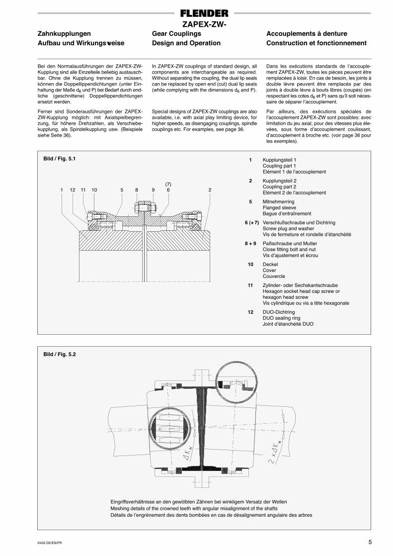
1 11 10 5 8 9 6 2
1 Kupplungsteil 1Coupling part 1Elément 1 de l’accouplement
2 Kupplungsteil 2Coupling part 2Elément 2 de l’accouplement
5 MitnehmerringFlanged sleeveBague d’entraînement
6 (+ 7) Verschlußschraube und DichtringScrew plug and washerVis de fermeture et rondelle d’étanchéité
8 + 9 Paßschraube und MutterClose fitting bolt and nutVis d’ajustement et écrou
10 DeckelCoverCouvercle
11 Zylinder- oder SechskantschraubeHexagon socket head cap screw orhexagon head screwVis cylindrique ou vis a tête hexagonale
12 DUO-DichtringDUO sealing ringJoint d’étanchéité DUO
12(7)
Bild / Fig. 5.1
Eingriffsverhältnisse an den gewölbten Zähnen bei winkligem Versatz der WellenMeshing details of the crowned teeth with angular misalignment of the shaftsDétails de l’engrènement des dents bombées en cas de désalignement angulaire des arbres
Bild / Fig. 5.2
K432 DE/EN/FR6
ZAPEX-ZW-ZahnkupplungenÜberschlägige Ermittlung derKupplungsgröße mittels Betriebsfaktor
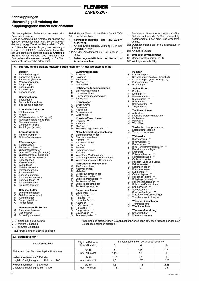
Die angegebenen Belastungskennwerte sindDurchschnittswerte.Genaue Auslegung auf Anfrage bei Angabe dergenauen Betriebsbedingungen. Bei der Auswahlder Kupplungsgröße ist der Betriebsfaktor f1 (Ta-fel 6.II) – unter Berücksichtigung des Belastungs-kennwertes (Tafel 6.I) – zu berücksichtigen. Die-ser Betriebsfaktor beinhaltet bis zu 25 Anläufe jeStunde, wobei während des Anlaufens das2-fache Nenndrehmoment zulässig ist. Darüber-hinaus ist Rücksprache erforderlich.
Bei winkligem Versatz ist der Faktor f2 nach Tafel9.I zu berücksichtigen.1. Verwendungszweck der ZAPEX-ZW-
Kupplung1.1 Art der Kraftmaschine, Leistung P1 in kW,
Drehzahl n1 min-1
1.2 Art der Arbeitsmaschine, Soll-Leistung P2in kW
2. Belastungsverhältnisse der Kraft- undArbeitsmaschine
2.1 Betriebsart: Gleich- oder ungleichmäßigerBetrieb, auftretende Stöße. Massenträg-heitsmomente J der Kraft- und Arbeitsma-schine.
2.2 Durchschnittliche tägliche Betriebsdauer inStunden
2.3 Anläufe je Stunde
3. Umgebungsverhältnisse3.1 Umgebungstemperatur in �C3.2 Winkliger Versatz ∆Kw
6.I Zuordnung des Belastungskennwertes nach der Art der Arbeitsmaschine
BaggerS EimerkettenbaggerS Fahrwerke (Raupe)M Fahrwerke (Schiene)M ManöverierwindenM SaugpumpenS SchaufelräderS SchneidköpfeM Schwenkwerke
BaumaschinenM BauaufzügeM BetonmischmaschinenM Straßenbaumaschinen
Chemische IndustrieM Kühltrommeln **M MischerG Rührwerke (leichte Flüssigkeit)M Rührwerke (zähe Flüssigkeit)M Trockentrommeln **G Zentrifugen (leicht)M Zentrifugen (schwer)
ErdölgewinnungM Pipeline-Pumpen **S Rotary-Bohranlagen
FörderanlagenM FörderhaspelnS Fördermaschinen **M GliederbandfördererM Gurtbandförderer (Schüttgut)S Gurtbandförderer (Stückgut)M GurttaschenbecherwerkeM KettenbahnenM KreiselfördererM LastaufzügeG MehlbecherwerkeM PersonenaufzügeM PlattenbänderM SchneckenfördererM SchotterbecherwerkeS Schrägaufzüge **M StahlbandfördererM Trogkettenförderer
Gebläse, LüfterM DrehkolbengebläseG Gebläse (axial/radial)M KühlturmlüfterM SaugzuggebläseG Turbogebläse
Generatoren, UmformerS Frequenz-UmformerS GeneratorenS Schweißgeneratoren
GummimaschinenS Extruder **M Kalander **S Knetwerke **M Mischer **S Walzwerke **
HolzbearbeitungsmaschinenS EntrindungstrommelnM HobelmaschinenG HolzbearbeitungsmaschinenS Sägegatter **
KrananlagenG EinziehwerkeS FahrwerkeG HubwerkeM SchwenkwerkeM Wippwerke
KunststoffmaschinenM Extruder **M Kalander **M Mischer **M Zerkleinerungsmaschinen **
MetallbearbeitungsmaschinenM BlechbiegemaschinenS BlechrichtmaschinenS Hämmer **S HobelmaschinenS PressenM ScherenS SchmiedepressenS StanzenG Vorgelege, WellensträngeM Werkzeugmaschinen-HauptantriebeG Werkzeugmaschinen-Hilfsantriebe
NahrungsmittelmaschinenG AbfüllmaschinenM KnetmaschinenM MaischenG VerpackungsmaschinenM Zuckerrohrbrecher **M Zuckerrohrschneider **S Zuckerrohrmühlen **M ZuckerrübenschneiderM Zuckerrübenwäsche
PapiermaschinenS Gautschen **S Glättzylinder **S Holländer **S Holzschleifer **S Kalander **S Naßpressen **S Reißwölfe **S Saugpressen **S Saugwalzen **S Trockenzylinder **
PumpenS KolbenpumpenG Kreiselpumpen (leichte Flüssigkeit)M Kreiselpumpen (zähe Flüssigkeit)S Plungerpumpen **S Preßpumpen **
Steine, ErdenS BrecherS Drehöfen **S Hammermühlen **S Kugelmühlen **S Rohrmühlen **S Schlagmühlen **S Ziegelpressen
TextilmaschinenM AufwicklerM Druckerei-FärbereimaschinenM GerbfässerM ReißwölfeM Webstühle
Verdichter, KompressorenS KolbenkompressorenM Turbokompressoren
WalzwerkeS Blechscheren **M Blechwender **S Blockdrücker **S Block- und Brammenstraßen **S Blocktransportanlagen **M DrahtzügeS Entzunderbrecher **S Feinblechstraßen **S Grobblechstraßen **M Haspeln (Band und Draht)S Kaltwalzwerke **M Kettenschlepper **S Knüppelscheren **M Kühlbetten **M Querschlepper **M Rollgänge (leicht) **S Rollgänge (schwer) **M Rollenrichtmaschinen **S RohrschweißmaschinenM Saumscheren **S Schopfscheren **S Stranggußanlagen **M WalzenverstellvorrichtungenS Verschiebevorrichtungen
WäschereimaschinenM TrommeltrocknerM Waschmaschinen
WasseraufbereitungM Kreiselbelüfter **G Wasserschnecken
G = gleichmäßige Belastung Änderung des erforderlichen Belastungskennwertes kann ggf. nach Angabe der genauenM = mittlere Belastung Betriebsbedingungen erfolgen.S = schwere Belastung
** Nur für 24-Stunden-Betrieb auslegen
6.II Betriebsfaktor f1
Antriebsmaschine Tägliche Betriebs- Belastungskennwert der ArbeitsmaschineAntriebsmaschine Tägliche Betriebs
dauer (Stunden) G M S
Elektromotoren, Turbinen, Hydraulikmotoren bis 10über 10 bis 24
11,25
1,251,5
1,752
Kolbenmaschinen 4 - 6 ZylinderUngleichförmigkeitsgrad 1 : 100 bis 1 : 200
bis 10über 10 bis 24
1,251,5
1,51,75
22,25
Kolbenmaschinen 1 - 3 ZylinderUngleichförmigkeitsgrad bis 1 : 100
bis 10über 10 bis 24
1,51,75
1,752
2,252,5
K432 DE/EN/FR 7
ZAPEX-ZW-Gear CouplingsRough Estimation of the CouplingSize by Means of the Service Factor
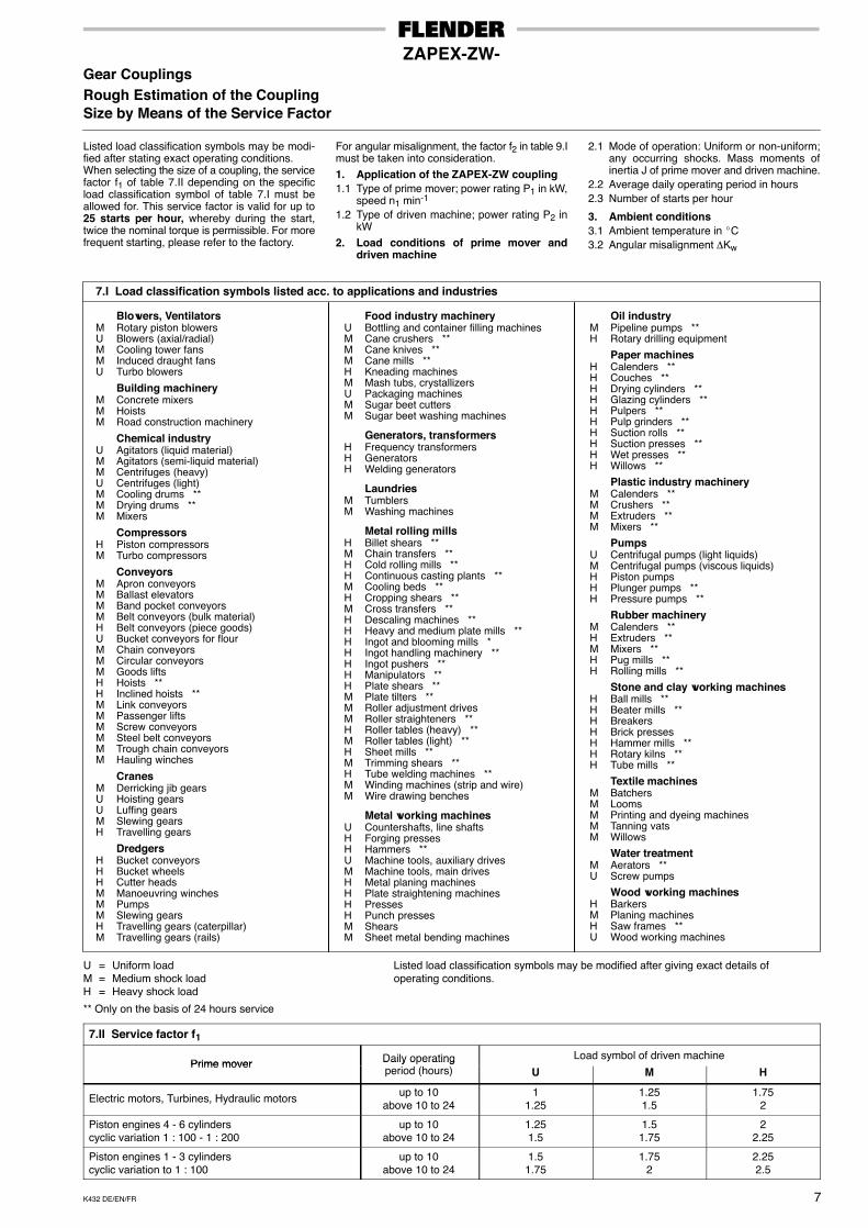
Listed load classification symbols may be modi-fied after stating exact operating conditions.When selecting the size of a coupling, the servicefactor f1 of table 7.II depending on the specificload classification symbol of table 7.I must beallowed for. This service factor is valid for up to25 starts per hour, whereby during the start,twice the nominal torque is permissible. For morefrequent starting, please refer to the factory.
For angular misalignment, the factor f2 in table 9.Imust be taken into consideration.1. Application of the ZAPEX-ZW coupling1.1 Type of prime mover; power rating P1 in kW,
speed n1 min-1
1.2 Type of driven machine; power rating P2 inkW
2. Load conditions of prime mover anddriven machine
2.1 Mode of operation: Uniform or non-uniform;any occurring shocks. Mass moments ofinertia J of prime mover and driven machine.
2.2 Average daily operating period in hours2.3 Number of starts per hour
3. Ambient conditions3.1 Ambient temperature in �C3.2 Angular misalignment ∆Kw
7.I Load classification symbols listed acc. to applications and industries
Blowers, VentilatorsM Rotary piston blowersU Blowers (axial/radial)M Cooling tower fansM Induced draught fansU Turbo blowers
Building machineryM Concrete mixersM HoistsM Road construction machinery
Chemical industryU Agitators (liquid material)M Agitators (semi-liquid material)M Centrifuges (heavy)U Centrifuges (light)M Cooling drums **M Drying drums **M Mixers
CompressorsH Piston compressorsM Turbo compressors
ConveyorsM Apron conveyorsM Ballast elevatorsM Band pocket conveyorsM Belt conveyors (bulk material)H Belt conveyors (piece goods)U Bucket conveyors for flourM Chain conveyorsM Circular conveyorsM Goods liftsH Hoists **H Inclined hoists **M Link conveyorsM Passenger liftsM Screw conveyorsM Steel belt conveyorsM Trough chain conveyorsM Hauling winches
CranesM Derricking jib gearsU Hoisting gearsU Luffing gearsM Slewing gearsH Travelling gears
DredgersH Bucket conveyorsH Bucket wheelsH Cutter headsM Manoeuvring winchesM PumpsM Slewing gearsH Travelling gears (caterpillar)M Travelling gears (rails)
Food industry machineryU Bottling and container filling machinesM Cane crushers **M Cane knives **M Cane mills **H Kneading machinesM Mash tubs, crystallizersU Packaging machinesM Sugar beet cuttersM Sugar beet washing machines
Generators, transformersH Frequency transformersH GeneratorsH Welding generators
LaundriesM TumblersM Washing machines
Metal rolling millsH Billet shears **M Chain transfers **H Cold rolling mills **H Continuous casting plants **M Cooling beds **H Cropping shears **M Cross transfers **H Descaling machines **H Heavy and medium plate mills **H Ingot and blooming mills *H Ingot handling machinery **H Ingot pushers **H Manipulators **H Plate shears **M Plate tilters **M Roller adjustment drivesM Roller straighteners **H Roller tables (heavy) **M Roller tables (light) **H Sheet mills **M Trimming shears **H Tube welding machines **M Winding machines (strip and wire)M Wire drawing benches
Metal working machinesU Countershafts, line shaftsH Forging pressesH Hammers **U Machine tools, auxiliary drivesM Machine tools, main drivesH Metal planing machinesH Plate straightening machinesH PressesH Punch pressesM ShearsM Sheet metal bending machines
Oil industryM Pipeline pumps **H Rotary drilling equipment
Paper machinesH Calenders **H Couches **H Drying cylinders **H Glazing cylinders **H Pulpers **H Pulp grinders **H Suction rolls **H Suction presses **H Wet presses **H Willows **
Plastic industry machineryM Calenders **M Crushers **M Extruders **M Mixers **
PumpsU Centrifugal pumps (light liquids)M Centrifugal pumps (viscous liquids)H Piston pumpsH Plunger pumps **H Pressure pumps **
Rubber machineryM Calenders **H Extruders **M Mixers **H Pug mills **H Rolling mills **
Stone and clay working machinesH Ball mills **H Beater mills **H BreakersH Brick pressesH Hammer mills **H Rotary kilns **H Tube mills **
Textile machinesM BatchersM LoomsM Printing and dyeing machinesM Tanning vatsM Willows
Water treatmentM Aerators **U Screw pumps
Wood working machinesH BarkersM Planing machinesH Saw frames **U Wood working machines
U = Uniform load Listed load classification symbols may be modified after giving exact details ofM = Medium shock load operating conditions.H = Heavy shock load
** Only on the basis of 24 hours service
7.II Service factor f1
Prime mover Daily operating Load symbol of driven machinePrime mover Daily o erating
period (hours) U M H
Electric motors, Turbines, Hydraulic motors up to 10above 10 to 24
11.25
1.251.5
1.752
Piston engines 4 - 6 cylinderscyclic variation 1 : 100 - 1 : 200
up to 10above 10 to 24
1.251.5
1.51.75
22.25
Piston engines 1 - 3 cylinderscyclic variation to 1 : 100
up to 10above 10 to 24
1.51.75
1.752
2.252.5
K432 DE/EN/FR8
ZAPEX-ZW-Accouplements à dentureSélection de la taille des accouplementspar l’utilisation du facteur service
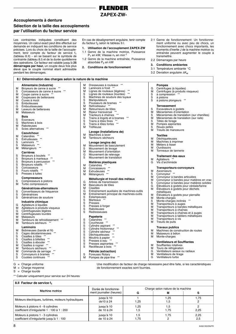
Les contraintes indiquées constituent desmoyennes. Un calcul exact peut être effectué surdemande en indiquant les conditions de serviceprécises. Lors du choix de la taille de l’accouple-ment, tenir compte du facteur de service f1(tableau 8.II) – en se basant sur le symbole decontrainte (tableau 8.I) et de la durée quotidiennedes opérations. Ce facteur est valable jusqu’à 25démarrages par heur, un couple deux fois plusélevé que le couple nominal étant admissiblependant les démarrages.
En cas de désalignement angulaire, tenir comptedu facteur f2 selon le tableau 9.I.
1. Utilisation de l’accouplement ZAPEX-ZW1.1 Genre de la machine motrice, Puissance
P1 en kW, Vitesse n1 en min-1
1.2 Genre de la machine entraînée, Puissanceabsorbée P2 en kW
2. Conditions de fonctionnement
2.1 Genre de fonctionnement: Un fonctionne-ment uniforme ou avec peu de chocs, unfonctionnement avec chocs importants, lesmoments d’inertie J de la machine motrice ouentraînée peuvent augmenter le couple àtransmettre.
2.2 Démarrages par heure
3. Conditions ambiantes3.1 Température ambiante �C3.2 Deviation angulaire ∆Kw
8.I Détermination des charges selon la nature de la machine
Alimentaire (Industrie)M Broyeurs de canne à sucre **S Concasseurs de canne à sucre **M Coupe canne à sucre **M Coupeuses de betteravesM Cuves à moûtG EmboiteusesG EmboutisseusesM Laveurs de betteravesM Malaxeurs
BoisS EcorceursG Machines à boisM RaboteusesS Scies alternatives **
CaoutchoucM Calandres **S Extrudeuses **S Laminoirs **S Malaxeurs **M Mélangeurs **
CarrièresS Broyeurs à boulets **S Broyeurs à marteaux **S Broyeurs à percussion **S Broyeurs rotatifs **S ConcasseursS Fours rotatifs **S Presses à tuiles
CompresseursS Compresseurs à pistonsM Turbo compresseurs
Génératrices-alternateursS Convertisseurs de fréquenceS GénératricesS Génératrices de soudure
Industrie chimiqueG Agitateurs à liquidesM Agitateurs à produits visqueuxG Centrifugeuses légèresM Centrifugeuses lourdesM MalaxeursM Tambours de refroidissement **M Tambours sécheurs **
LaminoirsM Bobineuses (bande et fil)S Cages décalamineuses **S Cisailles à tôles **S Cisailles à billettes **S Cisailles à ébouter **M Cisailles à rogner **M Tambours sécheurs **M Commande de serrage **S Convoyeurs à brames **S Coulées continues **
M Dresseuses à rouleaux **M Laminoirs à froid **M Lignes de rouleaux (légères) **S Lignes de rouleaux (lourdes) **S Machines de soudure des tuyauxS ManipulateursS Pousseurs de brames **M Refroidisseur **M Retourneurs de tôlesM Ripeur transversal **M Tracteurs à chaînes **S Trains à lingots et à brames **S Trains à tôles fines **S Trains à tôles fortes **M Tréfileuse
Lavage (Installations de)M Machines à laverM Tambours sécheurs
Levage (engins de)M Mouvement de basculementS Mouvement de levageM Mouvement d’orientationG Mouvement de relevageS Mouvement de translation
Matières plastiquesM Calandres **M Concasseurs **M Extrudeuses **M Mélangeurs **
Métallurgie et travail des métauxG Arbres de transmissionM Basculeurs de tôlesM CisaillesG Entraînement auxiliaire de machines-outilsM Entraînement principal de machines-outilsS EstampeusesS Marteaux **S PressesS Presses à forgerS RaboteusesS Redresseuses
PapeterieS Calandres **S Coucheuse **S Cylindre aspirant **S Cylindre frictionneur **S Cylindre sécheur **S Déchiqueteuses **S Moulins à papier **S Presses à eau **S Presses aspirantes **S Rectifieuse à bois **
Pétrole (extraction)S Foreuses RotaryM Pompes de pipe-line **
PompesG Centrifuges (à liquides)M Centrifuges (à produits visqueux)S à compression **S à pistonsS à pistons plongeurs **
TerrassementS Excavateurs à godetsM Mécanismes d’orientationS Mécanismes de translation (sur chenilles)M Mécanismes de translation (sur rails)S Têtes de forageM Pompes aspirantesS Roues pellesM Treuils de manoeuvre
TextilesM DéchiqueteusesM Machines à imprimerM Métiers à tisserM OurdissoirsM Tonneaux de tannerie
Traitement des eauxM Agitateurs **G Vis d’archimède
Transporteurs-convoyeursM AscenseursS Convoyeur **M Convoyeur à bandes articuléesM Convoyeur à bandes pour matières en vracS Convoyeur à bandes pour matières solidesG Élévateurs à godets pour céréale/farineM Élévateurs à godets pour déchets
métalliquesM Élévateurs à godets pour pierrailleM Monte-chargesS Monte-charges inclinés **M Transporteurs à augesM Transporteurs à bandes métalliquesM Transporteurs à chaînesM Transporteurs à chaînes et à augesM Transporteurs à tabliers métalliquesM Transporteurs à visM Treuils de puits
Travaux publicsM Machines de construction de routesM Malaxeurs à bétonM Monte-charges
Ventilateurs et SoufflantesM Soufflantes rotativesM Tours de réfrigérationG Ventilateurs axiaux ou radiauxM Ventilateurs de tirageG Ventilateurs turbo
G = Charge uniforme Une modification de facteur de charge nécessaire peut être faite, si les caractéristiquesM = Charge moyenne de fonctionnement exactes sont fournies.S = Charge lourde
** Calculer uniquement pour service sur 24 heures
8.II Facteur de service f1
Machine motriceDurée de fonctionne- Charge selon nature de la machine
Machine motriceDurée de fonctionne
ment journalier (heures) G M S
Moteurs électriques, turbines, moteurs hydrauliques jusqu’à 10de10 à 24
11,25
1,251,5
1,752
Moteurs à pistons 4 - 6 cylindrescoefficient d’irrégularité 1 : 100 à 1 : 200
jusqu’à 10de 10 à 24
1,251,5
1,51,75
22,25
Moteurs à pistons 1 - 3 cylindrescoefficient d’irrégularité jusqu’à 1 : 100
jusqu’à 10de 10 à 24
1,51,75
1,752
2,252,5
K432 DE/EN/FR 9
ZAPEX-ZW-Zahnkupplungen Gear Couplings Accouplements à dentureBerücksichtigung von Wellen- Making Allowance for Shaft Prise en compte de désaligne-verlagerungen Displacements ments des arbres
Verlagerungen von Wellenenden der mit ZAPEX-ZW-Kupplungen verbundenen Maschinen kön-nen verschiedene Ursachen haben. In gewissenFällen sind sie von vornherein unvermeidlich,oder sie treten durch elastische Verformungender Fundamente (z. B. Stahlgerüste) bzw. infolgevon Fundamentsetzungen auch nach längererZeit auf.
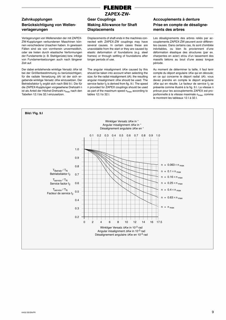
Der dabei entstehende winklige Versatz ∆Kw istbei der Größenbestimmung zu berücksichtigen;für die radiale Versetzung ∆Kr ist der sich er-gebende winklige Versatz ∆Kw einzusetzen. DerBetriebsfaktor f2 ergibt sich nach Bild 9.I. Die fürdie ZAPEX-Kupplungen vorgesehene Drehzahl nist als Anteil der Höchst-Drehzahl nmax nach denTabellen 12.I bis 32.I einzusetzen.
Displacements of shaft ends in the machines con-nected with ZAPEX-ZW couplings may haveseveral causes. In certain cases these areunavoidable from the start or they are caused byelastic deformation of foundations (e.g. steelframes) or through settling of foundations afterlonger periods of use.
The angular misalignment ∆Kw caused by thisshould be taken into account when selecting thesize; for the radial misalignment ∆Kr, the resultingangular misalignment ∆Kw should be used. Theservice factor f2 is derived from fig. 9.I. The speedn provided for ZAPEX couplings should be usedas part of the maximum speed nmax according totables 12.I to 32.I.
Les désalignements des arbres reliés par ac-couplements ZAPEX-ZW peuvent avoir différen-tes causes. Dans certains cas, ils sont d’embléeinévitables, ou bien ils proviennent d’unedéformation élastique des structures (par ex.charpentes en acier) et/ou d’un tassement desmassifs bétons au bout d’une assez longuepériode.
Au moment de déterminer la taille, il faut tenircompte du déport angulaire ∆Kw qui en découle;en ce qui concerne le déport radial ∆Kr, vousdevez prendre en compte le déport angulaire∆Kw qui en résulte. Le facteur de service f2 seprésente comme illustré à la fig. 9.I. La vitesse nprévue pour les accouplements ZAPEX est pro-portionnelle à la vitesse maximale nmax, commele montrent les tableaux 12.I à 32.I.
0.2
TBetrieb / TNBetriebsfaktor f2
0.1 0.2 0.3 0.4 0.5 0.6 0.7 0.8 0.9 1.0
2 4 6 8 10 12 14 16 17.50
0.3
0.4
0.5
0.6
0.7
0.8
0.9
1.0
Winkliger Versatz ∆Kw in 10-3 radAngular misalignment ∆Kw in 10-3 rad
Désalignement angulaire ∆Kw en 10-3 rad
n = 0.063�n max
n = 0.1�n max
n = 0.16�n max
n = 0.25�n max
n = 0.4�n max
n = n max
n = 0.63�n max
Bild / Fig. 9.I
Tservice / TNService factor f2
Tservice / TNFacteur de service f2
Winkliger Versatz ∆Kw in °Angular misalignment ∆Kw in °
Désalignement angulaire ∆Kw en °
K432 DE/EN/FR10
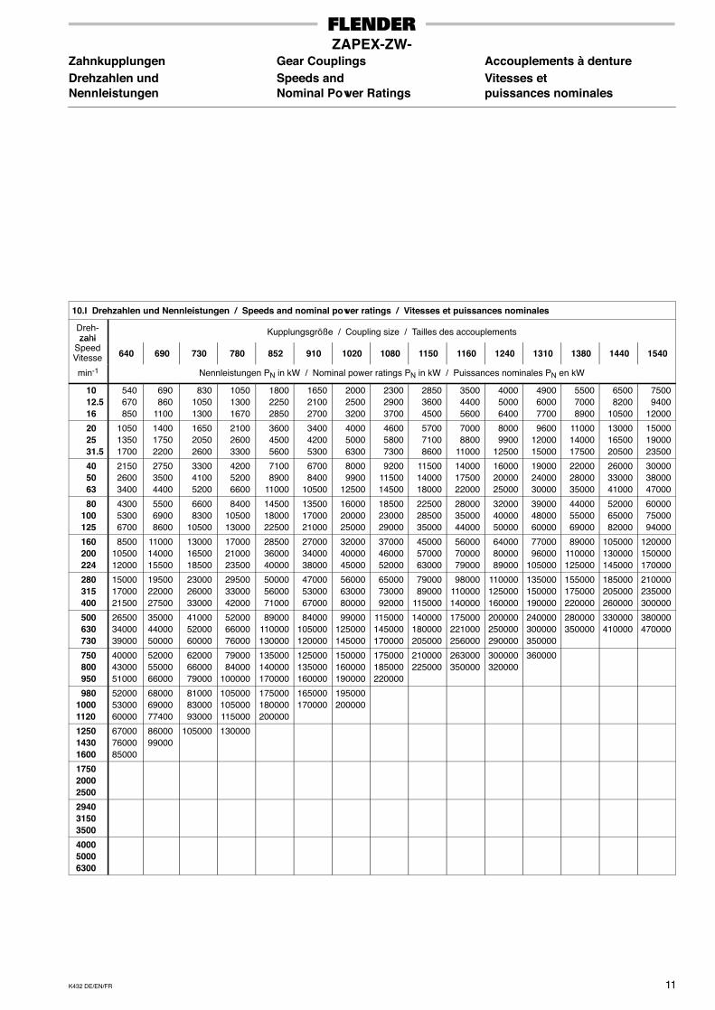
ZAPEX-ZW-Zahnkupplungen Gear Couplings Accouplements à dentureDrehzahlen und Speeds and Vitesses etNennleistungen Nominal Power Ratings puissances nominales
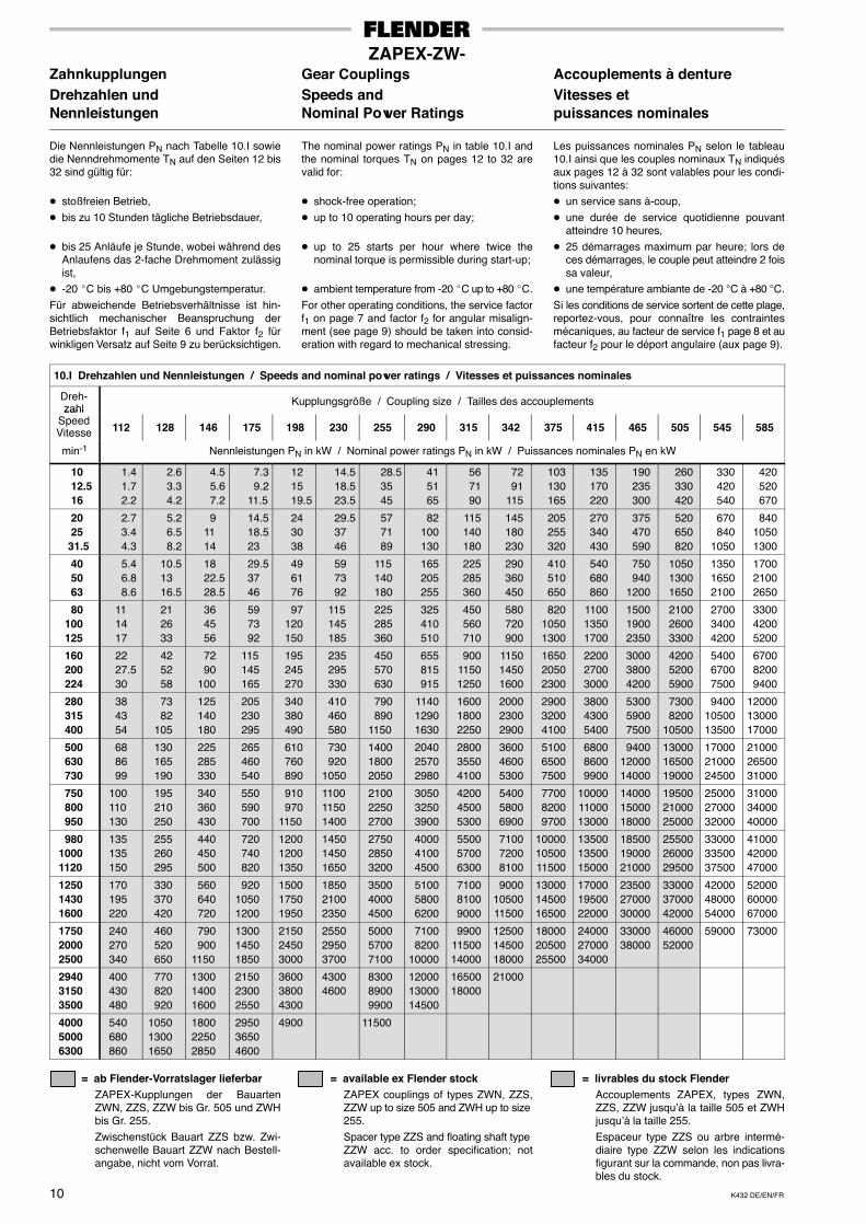
Die Nennleistungen PN nach Tabelle 10.I sowiedie Nenndrehmomente TN auf den Seiten 12 bis32 sind gültig für:
� stoßfreien Betrieb,� bis zu 10 Stunden tägliche Betriebsdauer,
� bis 25 Anläufe je Stunde, wobei während desAnlaufens das 2-fache Drehmoment zulässigist,
� -20 �C bis +80 �C Umgebungstemperatur.Für abweichende Betriebsverhältnisse ist hin-sichtlich mechanischer Beanspruchung derBetriebsfaktor f1 auf Seite 6 und Faktor f2 fürwinkligen Versatz auf Seite 9 zu berücksichtigen.
The nominal power ratings PN in table 10.I andthe nominal torques TN on pages 12 to 32 arevalid for:
� shock-free operation;� up to 10 operating hours per day;
� up to 25 starts per hour where twice thenominal torque is permissible during start-up;
� ambient temperature from -20 �C up to +80 �C.For other operating conditions, the service factorf1 on page 7 and factor f2 for angular misalign-ment (see page 9) should be taken into consid-eration with regard to mechanical stressing.
Les puissances nominales PN selon le tableau10.I ainsi que les couples nominaux TN indiquésaux pages 12 à 32 sont valables pour les condi-tions suivantes:� un service sans à-coup,� une durée de service quotidienne pouvant
atteindre 10 heures,� 25 démarrages maximum par heure; lors de
ces démarrages, le couple peut atteindre 2 foissa valeur,
� une température ambiante de -20 °C à +80 °C.Si les conditions de service sortent de cette plage,reportez-vous, pour connaître les contraintesmécaniques, au facteur de service f1 page 8 et aufacteur f2 pour le déport angulaire (aux page 9).
10.I Drehzahlen und Nennleistungen / Speeds and nominal power ratings / Vitesses et puissances nominales
Dreh-zahl
Kupplungsgröße / Coupling size / Tailles des accouplementszahl
SpeedVitesse 112 128 146 175 198 230 255 290 315 342 375 415 465 505 545 585
min-1 Nennleistungen PN in kW / Nominal power ratings PN in kW / Puissances nominales PN en kW
10 12.5 16
1.41.72.2
2.63.34.2
4.55.67.2
7.39.2
11.5
121519.5
14.518.523.5
28.53545
415165
567190
7291
115
103130165
135170220
190235300
260330420
330420540
420520670
20 2531.5
2.73.44.3
5.26.58.2
91114
14.518.523
243038
29.53746
577189
82100130
115140180
145180230
205255320
270340430
375470590
520650820
670840
1050
84010501300
40 50 63
5.46.88.6
10.51316.5
1822.528.5
29.53746
496176
597392
115140180
165205255
225285360
290360450
410510650
540680860
750940
1200
105013001650
135016502100
170021002650
80 100 125
111417
212633
364556
597392
97120150
115145185
225285360
325410510
450560710
580720900
82010501300
110013501700
150019002350
210026003300
270034004200
330042005200
160 200 224
2227.530
425258
7290
100
115145165
195245270
235295330
450570630
655815915
90011501250
115014501600
165020502300
220027003000
300038004200
420052005900
540067007500
670082009400
280 315 400
384354
7382
105
125140180
205230295
340380490
410460580
790890
1150
114012901630
160018002250
200023002900
290032004100
380043005400
530059007500
73008200
10500
94001050013500
120001300017000
500 630 730
688699
130165190
225285330
265460540
610760890
730920
1050
140018002050
204025702980
280035504100
360046005300
510065007500
680086009900
94001200014000
130001650019000
170002100024500
210002650031000
750 800 950
100110130
195210250
340360430
550590700
910970
1150
110011501400
210022502700
305032503900
420045005300
540058006900
770082009700
100001100013000
140001500018000
195002100025000
250002700032000
310003400040000
980 1000 1120
135135150
255260295
440450500
720740820
120012001350
145014501650
275028503200
400041004500
550057006300
710072008100
100001050011500
135001350015000
185001900021000
255002600029500
330003350037500
410004200047000
1250 1430 1600
170195220
330370420
560640720
92010501200
150017501950
185021002350
350040004500
510058006200
710081009000
90001050011500
130001450016500
170001950022000
235002700030000
330003700042000
420004800054000
520006000067000
1750 2000 2500
240270340
460520650
790900
1150
130014501850
215024503000
255029503700
500057007100
71008200
10000
99001150014000
125001450018000
180002050025500
240002700034000
3300038000
4600052000
59000 73000
2940 3150 3500
400430480
770820920
130014001600
215023002550
360038004300
43004600
830089009900
120001300014500
1650018000
21000
4000 5000 6300
540680860
105013001650
180022502850
295036504600
4900 11500
= ab Flender-Vorratslager lieferbarZAPEX-Kupplungen der BauartenZWN, ZZS, ZZW bis Gr. 505 und ZWHbis Gr. 255.Zwischenstück Bauart ZZS bzw. Zwi-schenwelle Bauart ZZW nach Bestell-angabe, nicht vom Vorrat.
= available ex Flender stockZAPEX couplings of types ZWN, ZZS,ZZW up to size 505 and ZWH up to size 255.Spacer type ZZS and floating shaft type ZZW acc. to order specification; notavailable ex stock.
= livrables du stock FlenderAccouplements ZAPEX, types ZWN,ZZS, ZZW jusqu’à la taille 505 et ZWHjusqu’à la taille 255.Espaceur type ZZS ou arbre intermé-diaire type ZZW selon les indicationsfigurant sur la commande, non pas livra-bles du stock.
K432 DE/EN/FR 11
ZAPEX-ZW-Zahnkupplungen Gear Couplings Accouplements à dentureDrehzahlen und Speeds and Vitesses etNennleistungen Nominal Power Ratings puissances nominales
10.I Drehzahlen und Nennleistungen / Speeds and nominal power ratings / Vitesses et puissances nominales
Dreh-zahl
Kupplungsgröße / Coupling size / Tailles des accouplementszahl
SpeedVitesse 640 690 730 780 852 910 1020 1080 1150 1160 1240 1310 1380 1440 1540
min-1 Nennleistungen PN in kW / Nominal power ratings PN in kW / Puissances nominales PN en kW
10 12.5 16
540670850
690860
1100
83010501300
105013001670
180022502850
165021002700
200025003200
230029003700
285036004500
350044005600
400050006400
490060007700
550070008900
65008200
10500
75009400
12000
20 25 31.5
105013501700
140017502200
165020502600
210026003300
360045005600
340042005300
400050006300
460058007300
570071008600
70008800
11000
80009900
12500
96001200015000
110001400017500
130001650020500
150001900023500
40 50 63
215026003400
275035004400
330041005200
420052006600
71008900
11000
67008400
10500
80009900
12500
92001150014500
115001400018000
140001750022000
160002000025000
190002400030000
220002800035000
260003300041000
300003800047000
80 100 125
430053006700
550069008600
66008300
10500
84001050013000
145001800022500
135001700021000
160002000025000
185002300029000
225002850035000
280003500044000
320004000050000
390004800060000
440005500069000
520006500082000
600007500094000
160 200 224
85001050012000
110001400015500
130001650018500
170002100023500
285003600040000
270003400038000
320004000045000
370004600052000
450005700063000
560007000079000
640008000089000
7700096000
105000
89000110000125000
105000130000145000
120000150000170000
280 315 400
150001700021500
195002200027500
230002600033000
295003300042000
500005600071000
470005300067000
560006300080000
650007300092000
7900089000
115000
98000110000140000
110000125000160000
135000150000190000
155000175000220000
185000205000260000
210000235000300000
500 630 730
265003400039000
350004400050000
410005200060000
520006600076000
89000110000130000
84000105000120000
99000125000145000
115000145000170000
140000180000205000
175000221000256000
200000250000290000
240000300000350000
280000350000
330000410000
380000470000
750 800 950
400004300051000
520005500066000
620006600079000
7900084000
100000
135000140000170000
125000135000160000
150000160000190000
175000185000220000
210000225000
263000350000
300000320000
360000
980 1000 1120
520005300060000
680006900077400
810008300093000
105000105000115000
175000180000200000
165000170000
195000200000
1250 1430 1600
670007600085000
8600099000
105000 130000
1750 2000 2500
2940 3150 3500
4000 5000 6300
K432 DE/EN/FR12
ZAPEX-ZWN-Zahnkupplungen Gear Couplings Accouplements à dentureNormalausführung Standard Design Exécution standard
D 1
l l
Pd 3
d 4
d a
D 2
d 6
S 1
Ausführung AAssembly AModèle A
1
S 2
1 2
S 3
1 2
Etanchéifier les gorges des clavettes lors dumontage afin que le lubrifiant ne puisse pas fuir.
Seal keyways against leaking of lubricanton assembly.
Paßfedernuten sind bei der Montage ge-gen Schmiermittelaustritt abzudichten.
2
Teil / Part / Partie 1
P
VA1 Teil / Part / Partie 2
Ausführung ABAssembly ABModèle AB
Ausführung BAssembly BModèle B
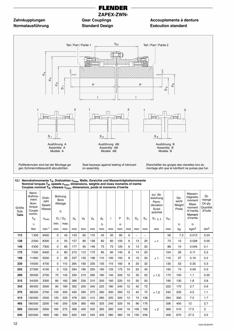
12.I Nenndrehmomente TN, Drehzahlen nmax, Maße, Gewichte und MassenträgheitsmomenteNominal torques TN, speeds nmax, dimensions, weights and mass moments of inertiaCouples nominal TN, vitesses nmax, dimensions, poids et moments d’inertie
GrößeSizeTaille
Nenn-drehmo-
mentNom.torqueCouplenomin.
Dreh-zahl
SpeedVitesse
BohrungBore
Alésage
2)
zul. Ab-weichung
Perm.deviation
Ecartautorisé
Ge-wicht
WeightPoids
Massen-trägheits-moment
Massmomentof inertiaMoment
Öl-mengeOil qty.
Quantitéd’huile
TailleTN nmax D1 / D2 da d3 d4 d6 l P S1 S2 S3 S1, 2, 3 VA1
Momentd‘inertie
1) min. max. 3) 4) 5) 5)
Nm min-1 mm mm mm mm mm mm mm mm mm mm mm mm mm kg kgm2 dm3
112 1 300 9400 0 45 143 65 110 45 50 85 6 – – 56 7.2 0.013 0.04
128 2 500 8300 0 55 157 80 128 60 60 105 6 13 20 + 1 73 10 0.028 0.05
146 4 300 7300 0 65 177 95 146 75 75 120 6 13 20 88 15 0.045 0.1
175 7 000 6400 0 80 215 112 175 85 90 140 8 14 20 104 26 0.11 0.2
198 11 600 5500 0 95 237 135 198 110 100 150 8 19 30 + 1 119 37 0.19 0.2
230 19 000 4700 0 110 265 160 230 135 110 160 8 20 32 130 53 0.35 0.3
255 27 000 4100 0 125 294 185 255 160 125 175 10 25 40 150 74 0.59 0.3
290 39 000 3700 70 145 330 210 290 180 140 200 10 30 50 + 1.5 170 100 1.1 0.55
315 54 000 3300 80 160 366 230 315 200 160 220 10 30 50 190 130 1.8 0.8
342 69 000 3000 90 180 392 255 340 225 180 240 12 42 72 222 170 2.7 0.9
375 98 000 2700 100 200 430 290 375 260 200 260 12 42 72 + 1.5 242 235 4.5 1.1
415 130 000 2500 120 220 478 320 415 285 220 300 12 74 136 294 300 7.2 1.7
465 180 000 2200 140 250 528 360 465 325 240 320 16 96 176 336 400 12 2.7
505 250 000 2000 160 275 568 400 505 365 260 340 16 106 196 + 2 366 510 17.5 3
545 320 000 1800 180 300 620 440 545 405 280 360 16 126 236 406 670 27.5 3.5
K432 DE/EN/FR 13
ZAPEX-ZWN-Zahnkupplungen Gear Couplings Accouplements à dentureNormalausführung Standard Design Exécution standard
GrößeSizeTaille
Nenn-drehmo-
mentNom.torqueCouplenomin.
Dreh-zahl
SpeedVitesse
BohrungBore
Alésage
2)
zul. Ab-wei-
chungPerm.devia-tion
Ecartautorisé
Ge-wicht
WeightPoids
Massen-trägheits-moment
Massmomentof inertiaMomentd‘inertie
Öl-mengeOil qty.Quan-
titéd’huile
TN nmax D1 / D2 da d3 d4 d6 l P S1 S2 S3 S1, 2, 3 VA1d‘inertie
1) min. max. 3) 4) 5) 5)
Nm min-1 mm mm mm mm mm mm mm mm mm mm mm mm mm kg kgm2 dm3
585 400 000 1700 210 330 660 480 585 445 310 390 20 150 280 460 830 40 4.5
640 510 000 1600 230> 330
330360
738 480 520
640 445 330 420 20 149 278 479 990 930
55 59
5
690 660 000 1450 250> 360
360390
788 520 560
690 475 350 440 20 166 312+ 2
516 1200 1100
79 83
7
730 790 000 1350 275> 390
390415
834 560 600
730 515 380 470 20 180 340 560 1450 1400
110 114
7.5
780 1 000 000 1250 300> 415
415450
900 600 650
780 555 400 510 25 176 327 576 1750 1750
150 170
8.5
852 1 200 000 1150 325> 450
450490
970 650 710
850 595 420 530 25 185 345
+ 3
605 2200 2150
225 240
9
910 1 600 000 1050 350> 490
490520
1030 710 750
910 655 450 560 25 215 405
+ 3
665 2700 2550
320 320
10.5
1020 1 900 000 1000 375> 520
520550
1112 750 800
1020 695 480 610 25 213 401 693 3300 3200
450 480
13.5
1080 2 200 000 950 400> 550
550600
1162 800 860
1080 735 500 635 30 226 422 726 3800 3700
580 630
14.5
1150 2 700 000 900 425> 600
600650
1222 860 930
1150 795 520 655 30 238 446 758 4600 4400
760 840
16
1160 3 350 000 850 450> 600> 650
600650690
1292 860 930 990
116011601210
795 550 685 30 260 490+ 3
810 5000 4900 5100
930 9801100
18.5
1240 3 800 000 800 475> 650> 690
650690730
1400 930 9901055
124012401290
865 580 735 30 250 470 830 6200 5800 6300
130013501550
23
1310 4 600 000 750
500> 650> 690> 730
650690730780
1470
930 99010551120
1310131013101370
850 610 765 35 265 495 875
6900 6600 7000 7400
1600165018502050
24.5
1380 5 300 000 700
525> 690> 730> 780
690730780810
1540
990105511201170
1380138013801430
910 640 795 35 275 515
+ 4
915
8000 7700 8100 8300
2050215023502500
34
1440 6 250 000 670
550> 730> 780> 810
730780810860
1600
1055112011701240
1440144014401510
975 670 825 35 295 555
+ 4
965
9400 8800 9000 9700
2650270029003200
40
1540 7 200 000 630
575> 780> 810> 860
780810860910
1710
1120117012401310
1540154015401610
1030 700 875 35 275 515 975
11000100001050012000
3500350038004200
44
Bis Größe 505 ab Flender-Vorratslager liefer-bar1) Die angegebenen Drehmomente beziehen
sich nicht auf die Wellen/Naben-Verbindung.Diese muß gesondert überprüft werden.
2) Max. Bohrung für Nut nach DIN 6885/1.
3) Zum Erneuern der Dichtringe erforderlicherDurchmesser.
4) Zum Erneuern der Dichtringe erforderlicheLänge.
5) Massenträgheitsmomente und Gewichtegelten für mittlere Bohrungen.
Up to size 505, available ex Flender stock
1) The torques listed do not refer to the shaft-hubfit.This must be checked separately.
2) Maximum bore for keyway to DIN 6885/1.
3) Diameter required for replacing sealing rings.
4) Length required for replacing sealing rings.
5) Mass moments of inertia and weights refer tomedium-sized bores.
Livrable du stock Flender jusqu’à la taille 505
1) Les couples indiqués ne se réfèrent pas à laliaison arbre/moyeu.Celle-ci doit être contrôlée à part.
2) Alésage max. pour rainure selon DIN 6885/1.
3) Diamètre requis pour le remplacement desjoints d’étanchéité.
4) Longueur requise pour le remplacement desjoints d’étanchéité.
5) Les moments d’inertie et les poids indiquéssont valables pour les alésages moyens.
K432 DE/EN/FR14
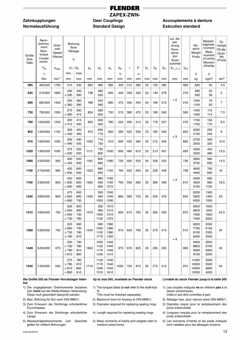
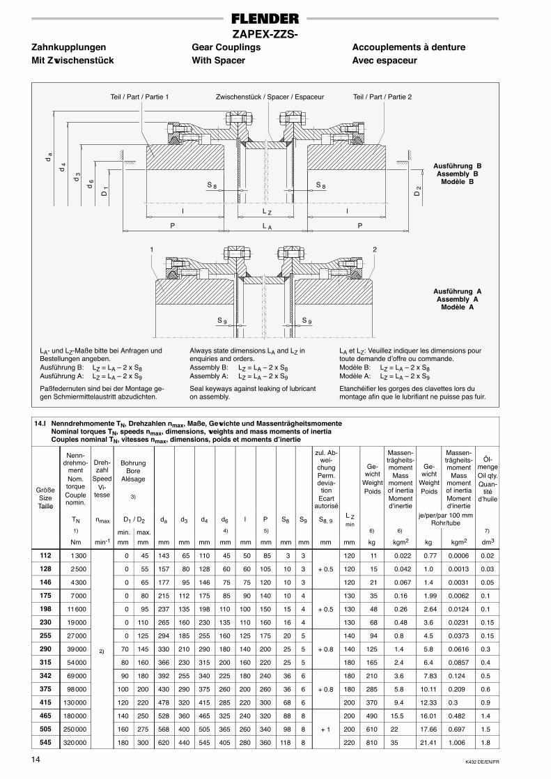
ZAPEX-ZZS-Zahnkupplungen Gear Couplings Accouplements à dentureMit Zwischenstück With Spacer Avec espaceur
D 1
P
d 3
d 4
d a
d 6
P
l lL Z
L A
S 8 S 8
D 2
Etanchéifier les gorges des clavettes lors dumontage afin que le lubrifiant ne puisse pas fuir.
Seal keyways against leaking of lubricanton assembly.
Paßfedernuten sind bei der Montage ge-gen Schmiermittelaustritt abzudichten.
LA et LZ: Veuillez indiquer les dimensions pourtoute demande d’offre ou commande.Modèle B: LZ = LA – 2 x S8Modèle A: LZ = LA – 2 x S9
Always state dimensions LA and LZ inenquiries and orders.Assembly B: LZ = LA – 2 x S8Assembly A: LZ = LA – 2 x S9
LA- und LZ-Maße bitte bei Anfragen undBestellungen angeben.Ausführung B: LZ = LA – 2 x S8Ausführung A: LZ = LA – 2 x S9
Teil / Part / Partie 1 Teil / Part / Partie 2
S 9 S 9
Ausführung BAssembly B
Modèle B
Ausführung AAssembly A
Modèle A
1 2
Zwischenstück / Spacer / Espaceur
14.I Nenndrehmomente TN, Drehzahlen nmax, Maße, Gewichte und MassenträgheitsmomenteNominal torques TN, speeds nmax, dimensions, weights and mass moments of inertiaCouples nominal TN, vitesses nmax, dimensions, poids et moments d’inertie
GrößeSizeTaille
Nenn-drehmo-
mentNom.torqueCouplenomin.
Dreh-zahl
SpeedVi-
tesse
BohrungBore
Alésage
3)
zul. Ab-wei-
chungPerm.devia-
tionEcart
autorisé
Ge-wicht
WeightPoids
Massen-trägheits-moment
Massmomentof inertiaMomentd‘inertie
Ge-wicht
WeightPoids
Massen-trägheits-moment
Massmomentof inertiaMomentd‘inertie
Öl-mengeOil qty.Quan-
titéd’huile
Taille
TN nmax D1 / D2 da d3 d4 d6 l P S8 S9 S8, 9L Zmin
je/per/par 100 mmRohr/tube
1) min. max. 4) 5) 6) 6) 7)
Nm min-1 mm mm mm mm mm mm mm mm mm mm mm mm kg kgm2 kg kgm2 dm3
112 1 300 0 45 143 65 110 45 50 85 3 3 120 11 0.022 0.77 0.0006 0.02
128 2 500 0 55 157 80 128 60 60 105 10 3 + 0.5 120 15 0.042 1.0 0.0013 0.03
146 4 300 0 65 177 95 146 75 75 120 10 3 120 21 0.067 1.4 0.0031 0.05
175 7 000 0 80 215 112 175 85 90 140 10 4 130 35 0.16 1.99 0.0062 0.1
198 11 600 0 95 237 135 198 110 100 150 15 4 + 0.5 130 48 0.26 2.64 0.0124 0.1
230 19 000 0 110 265 160 230 135 110 160 16 4 130 68 0.48 3.6 0.0231 0.15
255 27 000 0 125 294 185 255 160 125 175 20 5 140 94 0.8 4.5 0.0373 0.15
290 39 000 2) 70 145 330 210 290 180 140 200 25 5 + 0.8 140 125 1.4 5.8 0.0616 0.3
315 54 000
2)
80 160 366 230 315 200 160 220 25 5 180 165 2.4 6.4 0.0857 0.4
342 69 000 90 180 392 255 340 225 180 240 36 6 180 210 3.6 7.83 0.124 0.5
375 98 000 100 200 430 290 375 260 200 260 36 6 + 0.8 180 285 5.8 10.11 0.209 0.6
415 130 000 120 220 478 320 415 285 220 300 68 6 200 370 9.4 12.33 0.3 0.9
465 180 000 140 250 528 360 465 325 240 320 88 8 200 490 15.5 16.01 0.482 1.4
505 250 000 160 275 568 400 505 365 260 340 98 8 + 1 200 610 22 17.66 0.697 1.5
545 320 000 180 300 620 440 545 405 280 360 118 8 220 810 35 21.41 1.006 1.8
K432 DE/EN/FR 15
ZAPEX-ZZS-Zahnkupplungen Gear Couplings Accouplements à dentureMit Zwischenstück With Spacer Avec espaceur
GrößeSizeTaille
Nenn-drehmo-
mentNom.torqueCouplenomin.
Dreh-zahl
SpeedVi-
tesse
BohrungBore
Alésage
3)
zul.Abwei-chungPerm.devia-
tionEcart
autorisé
Ge-wicht
WeightPoids
Massen-trägheits-moment
Massmomentof inertiaMomentd‘inertie
Ge-wicht
WeightPoids
Massen-trägheits-moment
Massmomentof inertiaMomentd‘inertie
Öl-meng
eOilqty.
Quan-tité
d’huileTaille
TN nmax D1 / D2 da d3 d4 d6 l P S8 S9 S8, 9L Zmin
je/per/par 100mm Rohr/tube
1) min. max. 4) 5) 6) 6) 7)
Nm min-1 mm mm mm mm mm mm mm mm mm mm mm mm kg kgm2 kg kgm2 dm3
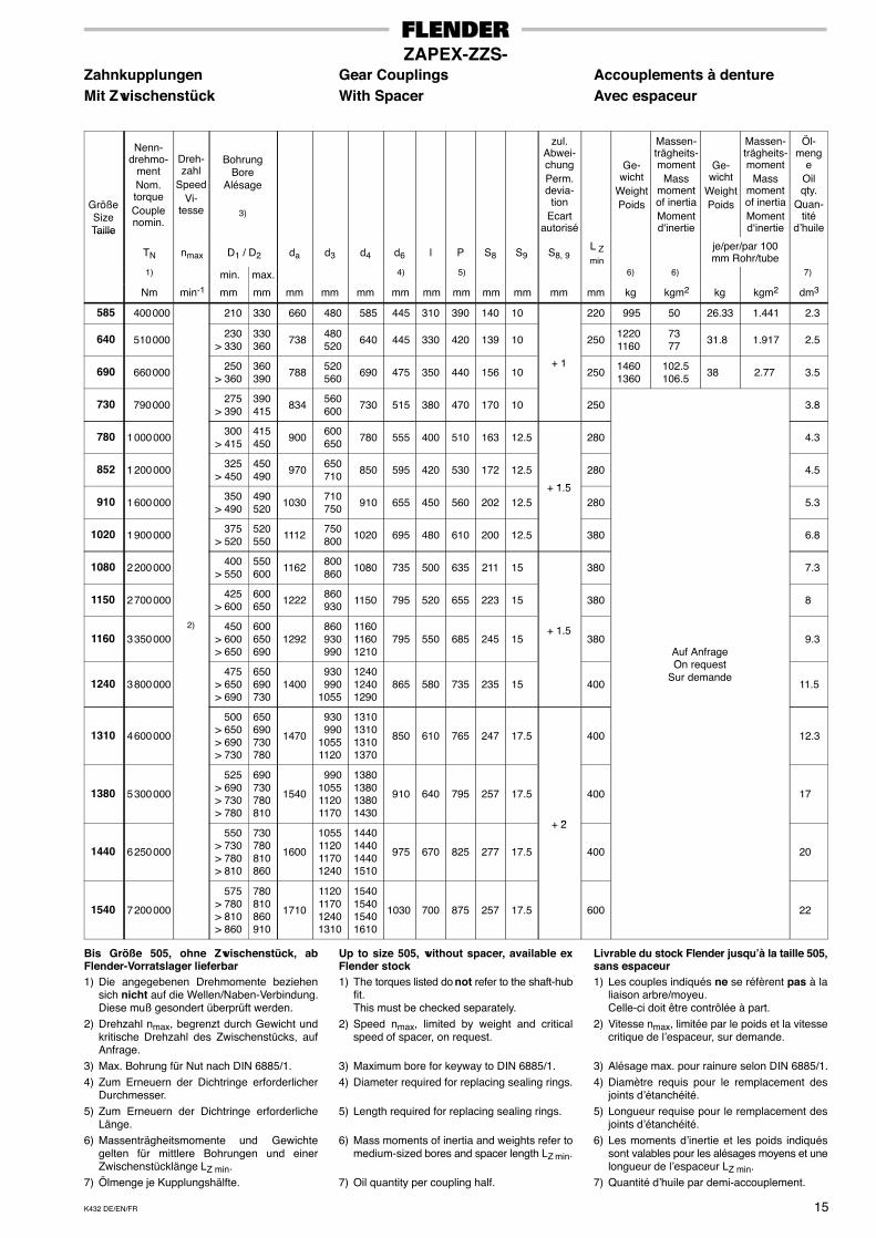
585 400 000 210 330 660 480 585 445 310 390 140 10 220 995 50 26.33 1.441 2.3
640 510 000 230> 330
330360 738 480
520 640 445 330 420 139 10 250 12201160
73 77 31.8 1.917 2.5
690 660 000 250> 360
360390 788 520
560 690 475 350 440 156 10+ 1
250 14601360
102.5106.5 38 2.77 3.5
730 790 000 275> 390
390415 834 560
600 730 515 380 470 170 10 250 3.8
780 1 000 000 300> 415
415450 900 600
650 780 555 400 510 163 12.5 280 4.3
852 1 200 000 325> 450
450490 970 650
710 850 595 420 530 172 12.5
+ 1 5
280 4.5
910 1 600 000 350> 490
490520 1030 710
750 910 655 450 560 202 12.5+ 1.5
280 5.3
1020 1 900 000 375> 520
520550 1112 750
800 1020 695 480 610 200 12.5 380 6.8
1080 2 200 000 400> 550
550600 1162 800
860 1080 735 500 635 211 15 380 7.3
1150 2 700 000 425> 600
600650 1222 860
930 1150 795 520 655 223 15 380 8
1160 3 350 0002) 450
> 600> 650
600650690
1292 860 930 990
116011601210
795 550 685 245 15+ 1.5
380Auf AnfrageO t
9.3
1240 3 800 000 475> 650> 690
650690730
1400 930 9901055
124012401290
865 580 735 235 15 400
gOn request
Sur demande11.5
1310 4 600 000
500> 650> 690> 730
650690730780
1470
930 99010551120
1310131013101370
850 610 765 247 17.5 400 12.3
1380 5 300 000
525> 690> 730> 780
690730780810
1540
990105511201170
1380138013801430
910 640 795 257 17.5
+ 2
400 17
1440 6 250 000
550> 730> 780> 810
730780810860
1600
1055112011701240
1440144014401510
975 670 825 277 17.5
+ 2
400 20
1540 7 200 000
575> 780> 810> 860
780810860910
1710
1120117012401310
1540154015401610
1030 700 875 257 17.5 600 22
Bis Größe 505, ohne Zwischenstück, abFlender-Vorratslager lieferbar1) Die angegebenen Drehmomente beziehen
sich nicht auf die Wellen/Naben-Verbindung.Diese muß gesondert überprüft werden.
2) Drehzahl nmax, begrenzt durch Gewicht undkritische Drehzahl des Zwischenstücks, aufAnfrage.
3) Max. Bohrung für Nut nach DIN 6885/1.4) Zum Erneuern der Dichtringe erforderlicher
Durchmesser.5) Zum Erneuern der Dichtringe erforderliche
Länge.6) Massenträgheitsmomente und Gewichte
gelten für mittlere Bohrungen und einerZwischenstücklänge LZ min.
7) Ölmenge je Kupplungshälfte.
Up to size 505, without spacer, available exFlender stock1) The torques listed do not refer to the shaft-hub
fit.This must be checked separately.
2) Speed nmax, limited by weight and criticalspeed of spacer, on request.
3) Maximum bore for keyway to DIN 6885/1.4) Diameter required for replacing sealing rings.
5) Length required for replacing sealing rings.
6) Mass moments of inertia and weights refer tomedium-sized bores and spacer length LZ min.
7) Oil quantity per coupling half.
Livrable du stock Flender jusqu’à la taille 505,sans espaceur1) Les couples indiqués ne se réfèrent pas à la
liaison arbre/moyeu.Celle-ci doit être contrôlée à part.
2) Vitesse nmax, limitée par le poids et la vitessecritique de l’espaceur, sur demande.
3) Alésage max. pour rainure selon DIN 6885/1.4) Diamètre requis pour le remplacement des
joints d’étanchéité.5) Longueur requise pour le remplacement des
joints d’étanchéité.6) Les moments d’inertie et les poids indiqués
sont valables pour les alésages moyens et unelongueur de l’espaceur LZ min.
7) Quantité d’huile par demi-accouplement.
K432 DE/EN/FR16
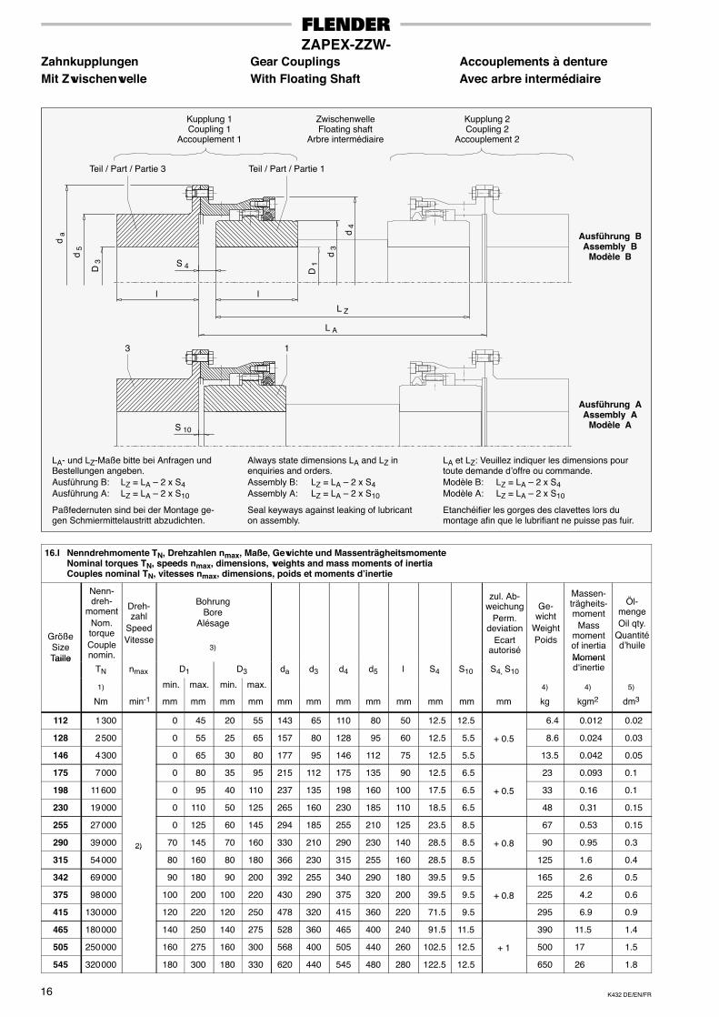
ZAPEX-ZZW-Zahnkupplungen Gear Couplings Accouplements à dentureMit Zwischenwelle With Floating Shaft Avec arbre intermédiaire
D 3
l
d 5
d 4
d a
L A
Etanchéifier les gorges des clavettes lors dumontage afin que le lubrifiant ne puisse pas fuir.
Seal keyways against leaking of lubricanton assembly.
Paßfedernuten sind bei der Montage ge-gen Schmiermittelaustritt abzudichten.
LA et LZ: Veuillez indiquer les dimensions pourtoute demande d’offre ou commande.Modèle B: LZ = LA – 2 x S4Modèle A: LZ = LA – 2 x S10
Always state dimensions LA and LZ inenquiries and orders.Assembly B: LZ = LA – 2 x S4Assembly A: LZ = LA – 2 x S10
LA- und LZ-Maße bitte bei Anfragen undBestellungen angeben.Ausführung B: LZ = LA – 2 x S4Ausführung A: LZ = LA – 2 x S10
Teil / Part / Partie 3 Teil / Part / Partie 1
l
Kupplung 1Coupling 1
Accouplement 1
S 4
S 10
Kupplung 2Coupling 2
Accouplement 2
ZwischenwelleFloating shaft
Arbre intermédiaire
d 3
D 1
Ausführung BAssembly B
Modèle B
Ausführung AAssembly A
Modèle A
3 1
L Z
16.I Nenndrehmomente TN, Drehzahlen nmax, Maße, Gewichte und MassenträgheitsmomenteNominal torques TN, speeds nmax, dimensions, weights and mass moments of inertiaCouples nominal TN, vitesses nmax, dimensions, poids et moments d’inertie
GrößeSizeTaille
Nenn-dreh-
momentNom.torqueCouplenomin.
Dreh-zahl
SpeedVitesse
BohrungBore
Alésage
3)
zul. Ab-weichung
Perm.deviation
Ecartautorisé
Ge-wicht
WeightPoids
Massen-trägheits-moment
Massmomentof inertiaMoment
Öl-mengeOil qty.
Quantitéd’huile
TailleTN nmax D1 D3 da d3 d4 d5 l S4 S10 S4, S10
Momentd‘inertie
1) min. max. min. max. 4) 4) 5)
Nm min-1 mm mm mm mm mm mm mm mm mm mm mm mm kg kgm2 dm3
112 1 300 0 45 20 55 143 65 110 80 50 12.5 12.5 6.4 0.012 0.02
128 2 500 0 55 25 65 157 80 128 95 60 12.5 5.5 + 0.5 8.6 0.024 0.03
146 4 300 0 65 30 80 177 95 146 112 75 12.5 5.5 13.5 0.042 0.05
175 7 000 0 80 35 95 215 112 175 135 90 12.5 6.5 23 0.093 0.1
198 11 600 0 95 40 110 237 135 198 160 100 17.5 6.5 + 0.5 33 0.16 0.1
230 19 000 0 110 50 125 265 160 230 185 110 18.5 6.5 48 0.31 0.15
255 27 000 0 125 60 145 294 185 255 210 125 23.5 8.5 67 0.53 0.15
290 39 000 2) 70 145 70 160 330 210 290 230 140 28.5 8.5 + 0.8 90 0.95 0.3
315 54 000
2)
80 160 80 180 366 230 315 255 160 28.5 8.5 125 1.6 0.4
342 69 000 90 180 90 200 392 255 340 290 180 39.5 9.5 165 2.6 0.5
375 98 000 100 200 100 220 430 290 375 320 200 39.5 9.5 + 0.8 225 4.2 0.6
415 130 000 120 220 120 250 478 320 415 360 220 71.5 9.5 295 6.9 0.9
465 180 000 140 250 140 275 528 360 465 400 240 91.5 11.5 390 11.5 1.4
505 250 000 160 275 160 300 568 400 505 440 260 102.5 12.5 + 1 500 17 1.5
545 320 000 180 300 180 330 620 440 545 480 280 122.5 12.5 650 26 1.8
K432 DE/EN/FR 17
ZAPEX-ZZW-Zahnkupplungen Gear Couplings Accouplements à dentureMit Zwischenwelle With Floating Shaft Avec arbre intermédiaire
GrößeSizeTaille
Nenn-dreh-
momentNom.torqueCouplenomin.
Dreh-zahl
SpeedVi-
tesse
BohrungBore
Alésage
3)
zul. Ab-wei-
chungPerm.
deviationEcart
autorisé
Ge-wicht
WeightPoids
Massen-trägheits-moment
Massmomentof inertiaMoment
Öl-mengeOil qty.
Quantitéd’huile
TailleTN nmax D1 D3 da d3 d4 d5 l S4 S10 S4, S10
Momentd‘inertie
1) min. max. min. max. 4) 4) 5)
Nm min-1 mm mm mm mm mm mm mm mm mm mm mm mm kg kgm2 dm3
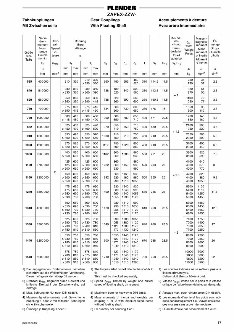
585 400 000 210 330 210> 330
330360
660 480 585 480 520
310 144.5 14.5 750 730
35 37
2.3
640 510 000 230> 330
330360
230> 360
360390
738 480 520
640 520 560
330 143.5 14.5
+ 1
930 870
51 55
2.5
690 660 000 250> 360
360390
250> 390
390415
788 520 560
690 560 600
350 160.5 14.5+ 1
1100 1050
72 77
3.5
730 790 000 275> 390
390415
275> 415
415450
834 560 600
730 600 650
380 176 16 1350 1300
98 110
3.8
780 1 000 000 300> 415
415450
300> 450
450490
900 600 650
780 650 710
400 171 20.5 1700 1650
140 160
4.3
852 1 200 000 325> 450
450490
325> 490
490520
970 650 710
850 710 750
420 180 20.5
+ 1 5
2100 1950
205 220
4.5
910 1 600 000 350> 490
490520
350> 520
520550
1030 710 750
910 750 800
450 210 20.5+ 1.5
2550 2350
285 300
5.3
1020 1 900 000 375> 520
520550
375> 550
550600
1112 750 800
1020 800 860
480 210 22.5 3100 2950
400 440
6.8
1080 2 200 000 400> 550
550600
400> 600
600650
1162 800 860
1080 860 930
500 221 25 3600 3500
520 590
7.3
1150 2 700 000
)
425 425> 600
600600650
425> 600> 650
600650690
1222 860 860 930
1150 860 930 990
520 233 25 4100 4000 4000
640 670 770
8
1160 3 350 000
2) 450> 600> 650
600650690
450> 650> 690
650690730
1292 860 930 990
116011601210
930 9601055
550 255 25+ 1.5 4700
4400 4800
820 8801050
9.3
1240 3 800 000
475 475> 650> 690
650650690730
475> 650> 690> 730
650690730780
1400
930 930 9901055
1240124012401290
930 99010551120
580 245 25
5500 5400 5400 5800
1100115012501450
11.5
1310 4 600 000
500> 650> 690> 730
650690730780
500> 690> 730> 780
690730780810
1470
930 99010551120
1310131013101370
990105511201170
610 258 28.5
6300 6000 6400 6800
1350145016501850
12.3
1380 5 300 000
525> 690> 730> 780
690730780810
525> 730> 780> 810
730780810860
1540
990105511201170
1380138013801430
1055112011701240
640 268 28.5
+ 2
7400 7000 7300 7700
1750190020502250
17
1440 6 250 000
550> 730> 780> 810
730780810860
550> 780> 810> 860
780810860910
1600
1055112011701240
1440144014401510
1120117012401310
670 288 28.5
+ 2 8600 7900 8300 9000
2300235026003000
20
1540 7 200 000
575> 780> 810> 860
780810860910
575> 575> 810> 860
810810860960
1710
1120117012401310
1540154015401610
1170117012401390
700 268 28.5
10000 9600 960011000
3000300032003900
22
1) Die angegebenen Drehmomente beziehensich nicht auf die Wellen/Naben-Verbindung.Diese muß gesondert überprüft werden.
2) Drehzahl nmax, begrenzt durch Gewicht undkritische Drehzahl der Zwischenwelle, aufAnfrage.
3) Max. Bohrung für Nut nach DIN 6885/1.
4) Massenträgheitsmomente und Gewichte jeKupplung 1 oder 2 mit mittleren Bohrungenohne Zwischenwelle.
5) Ölmenge je Kupplung 1 oder 2.
1) The torques listed do not refer to the shaft-hubfit.This must be checked separately.
2) Speed nmax, limited by weight and criticalspeed of floating shaft, on request.
3) Maximum bore for keyway to DIN 6885/1.
4) Mass moments of inertia and weights percoupling 1 or 2 with medium-sized boreswithout floating shaft.
5) Oil quantity per coupling 1 or 2.
1) Les couples indiqués ne se réfèrent pas à laliaison arbre/moyeu.Celle-ci doit être contrôlée à part.
2) Vitesse nmax, limitée par le poids et la vitessecritique de l’arbre intermédiaire, sur demande.
3) Alésage max. pour rainure selon DIN 6885/1.
4) Les moments d’inertie et les poids sont indi-qués par accouplement 1 ou 2 avec des alésa-ges moyens sans arbre intermédiaire.
5) Quantité d’huile par accouplement 1 ou 2.
K432 DE/EN/FR18
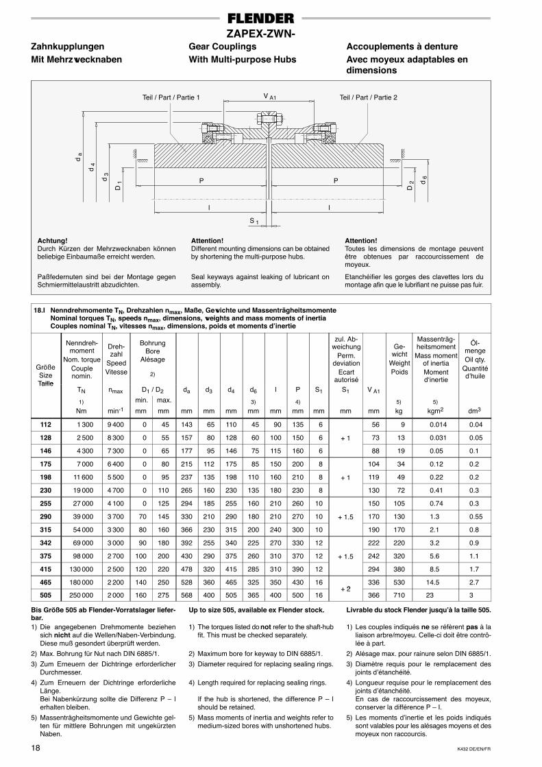
ZAPEX-ZWN-Zahnkupplungen Gear Couplings Accouplements à dentureMit Mehrzwecknaben With Multi-purpose Hubs Avec moyeux adaptables en
dimensions
D 1 Pd
3
d 4
d a
Etanchéifier les gorges des clavettes lors dumontage afin que le lubrifiant ne puisse pas fuir.
Seal keyways against leaking of lubricant onassembly.
Paßfedernuten sind bei der Montage gegenSchmiermittelaustritt abzudichten.
P
D 2 d
6
l l
S 1
V A1Teil / Part / Partie 1
Attention!Toutes les dimensions de montage peuventêtre obtenues par raccourcissement demoyeux.
Attention!Different mounting dimensions can be obtainedby shortening the multi-purpose hubs.
Achtung!Durch Kürzen der Mehrzwecknaben könnenbeliebige Einbaumaße erreicht werden.
Teil / Part / Partie 2
18.I Nenndrehmomente TN, Drehzahlen nmax, Maße, Gewichte und MassenträgheitsmomenteNominal torques TN, speeds nmax, dimensions, weights and mass moments of inertiaCouples nominal TN, vitesses nmax, dimensions, poids et moments d’inertie
GrößeSizeTaille
Nenndreh-moment
Nom. torqueCouplenomin.
Dreh-zahl
SpeedVitesse
BohrungBore
Alésage
2)
zul. Ab-weichung
Perm.deviation
Ecartautorisé
Ge-wicht
WeightPoids
Massenträg-heitsmoment
Mass momentof inertiaMomentd‘inertie
Öl-mengeOil qty.
Quantitéd’huile
TailleTN nmax D1 / D2 da d3 d4 d6 l P S1 S1 V A1
1) min. max. 3) 4) 5) 5)
Nm min-1 mm mm mm mm mm mm mm mm mm mm mm kg kgm2 dm3
112 1 300 9 400 0 45 143 65 110 45 90 135 6 56 9 0.014 0.04
128 2 500 8 300 0 55 157 80 128 60 100 150 6 + 1 73 13 0.031 0.05
146 4 300 7 300 0 65 177 95 146 75 115 160 6 88 19 0.05 0.1
175 7 000 6 400 0 80 215 112 175 85 150 200 8 104 34 0.12 0.2
198 11 600 5 500 0 95 237 135 198 110 160 210 8 + 1 119 49 0.22 0.2
230 19 000 4 700 0 110 265 160 230 135 180 230 8 130 72 0.41 0.3
255 27 000 4 100 0 125 294 185 255 160 210 260 10 150 105 0.74 0.3
290 39 000 3 700 70 145 330 210 290 180 210 270 10 + 1.5 170 130 1.3 0.55
315 54 000 3 300 80 160 366 230 315 200 240 300 10 190 170 2.1 0.8
342 69 000 3 000 90 180 392 255 340 225 270 330 12 222 220 3.2 0.9
375 98 000 2 700 100 200 430 290 375 260 310 370 12 + 1.5 242 320 5.6 1.1
415 130 000 2 500 120 220 478 320 415 285 310 390 12 294 380 8.5 1.7
465 180 000 2 200 140 250 528 360 465 325 350 430 16+ 2
336 530 14.5 2.7
505 250 000 2 000 160 275 568 400 505 365 400 500 16+ 2
366 710 23 3
Bis Größe 505 ab Flender-Vorratslager liefer-bar.1) Die angegebenen Drehmomente beziehen
sich nicht auf die Wellen/Naben-Verbindung.Diese muß gesondert überprüft werden.
2) Max. Bohrung für Nut nach DIN 6885/1.
3) Zum Erneuern der Dichtringe erforderlicherDurchmesser.
4) Zum Erneuern der Dichtringe erforderlicheLänge.Bei Nabenkürzung sollte die Differenz P – lerhalten bleiben.
5) Massenträgheitsmomente und Gewichte gel-ten für mittlere Bohrungen mit ungekürztenNaben.
Up to size 505, available ex Flender stock.
1) The torques listed do not refer to the shaft-hubfit. This must be checked separately.
2) Maximum bore for keyway to DIN 6885/1.
3) Diameter required for replacing sealing rings.
4) Length required for replacing sealing rings.
If the hub is shortened, the difference P – lshould be retained.
5) Mass moments of inertia and weights refer tomedium-sized bores with unshortened hubs.
Livrable du stock Flender jusqu’à la taille 505.
1) Les couples indiqués ne se réfèrent pas à laliaison arbre/moyeu. Celle-ci doit être contrô-lée à part.
2) Alésage max. pour rainure selon DIN 6885/1.
3) Diamètre requis pour le remplacement desjoints d’étanchéité.
4) Longueur requise pour le remplacement desjoints d’étanchéité.En cas de raccourcissement des moyeux,conserver la différence P – I.
5) Les moments d’inertie et les poids indiquéssont valables pour les alésages moyens et desmoyeux non raccourcis.
K432 DE/EN/FR 19
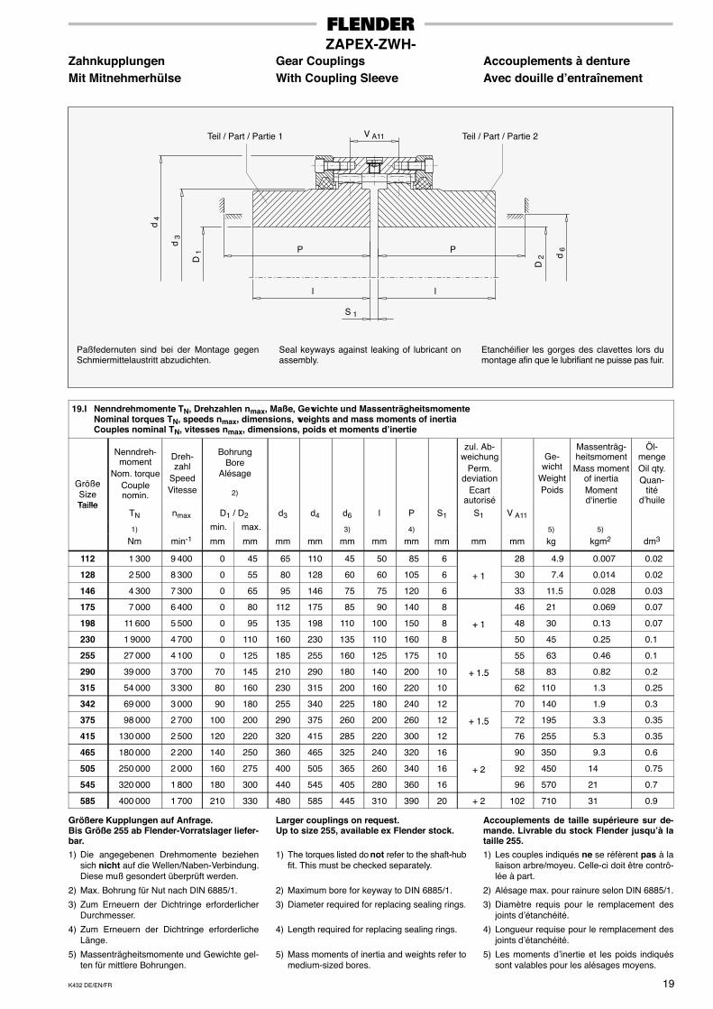
ZAPEX-ZWH-Zahnkupplungen Gear Couplings Accouplements à dentureMit Mitnehmerhülse With Coupling Sleeve Avec douille d’entraînement
D 1 P
d 3
d 4
Etanchéifier les gorges des clavettes lors dumontage afin que le lubrifiant ne puisse pas fuir.
Seal keyways against leaking of lubricant onassembly.
Paßfedernuten sind bei der Montage gegenSchmiermittelaustritt abzudichten.
P
l l
D 2 d
6
S 1
Teil / Part / Partie 1 Teil / Part / Partie 2V A11
19.I Nenndrehmomente TN, Drehzahlen nmax, Maße, Gewichte und MassenträgheitsmomenteNominal torques TN, speeds nmax, dimensions, weights and mass moments of inertiaCouples nominal TN, vitesses nmax, dimensions, poids et moments d’inertie
GrößeSizeTaille
Nenndreh-moment
Nom. torqueCouplenomin.
Dreh-zahl
SpeedVitesse
BohrungBore
Alésage
2)
zul. Ab-weichung
Perm.deviation
Ecartautorisé
Ge-wicht
WeightPoids
Massenträg-heitsmoment
Mass momentof inertiaMomentd‘inertie
Öl-mengeOil qty.Quan-
titéd’huileTaille
TN nmax D1 / D2 d3 d4 d6 l P S1 S1 V A11
1) min. max. 3) 4) 5) 5)
Nm min-1 mm mm mm mm mm mm mm mm mm mm kg kgm2 dm3
112 1 300 9 400 0 45 65 110 45 50 85 6 28 4.9 0.007 0.02
128 2 500 8 300 0 55 80 128 60 60 105 6 + 1 30 7.4 0.014 0.02
146 4 300 7 300 0 65 95 146 75 75 120 6
+ 1
33 11.5 0.028 0.03
175 7 000 6 400 0 80 112 175 85 90 140 8 46 21 0.069 0.07
198 11 600 5 500 0 95 135 198 110 100 150 8 + 1 48 30 0.13 0.07
230 1 9000 4 700 0 110 160 230 135 110 160 8
+ 1
50 45 0.25 0.1
255 27 000 4 100 0 125 185 255 160 125 175 10 55 63 0.46 0.1
290 39 000 3 700 70 145 210 290 180 140 200 10 + 1.5 58 83 0.82 0.2
315 54 000 3 300 80 160 230 315 200 160 220 10
+ 1.5
62 110 1.3 0.25
342 69 000 3 000 90 180 255 340 225 180 240 12 70 140 1.9 0.3
375 98 000 2 700 100 200 290 375 260 200 260 12 + 1.5 72 195 3.3 0.35
415 130 000 2 500 120 220 320 415 285 220 300 12
+ 1.5
76 255 5.3 0.35
465 180 000 2 200 140 250 360 465 325 240 320 16 90 350 9.3 0.6
505 250 000 2 000 160 275 400 505 365 260 340 16 + 2 92 450 14 0.75
545 320 000 1 800 180 300 440 545 405 280 360 16
+ 2
96 570 21 0.7
585 400 000 1 700 210 330 480 585 445 310 390 20 + 2 102 710 31 0.9
Größere Kupplungen auf Anfrage.Bis Größe 255 ab Flender-Vorratslager liefer-bar.
1) Die angegebenen Drehmomente beziehensich nicht auf die Wellen/Naben-Verbindung.Diese muß gesondert überprüft werden.
2) Max. Bohrung für Nut nach DIN 6885/1.
3) Zum Erneuern der Dichtringe erforderlicherDurchmesser.
4) Zum Erneuern der Dichtringe erforderlicheLänge.
5) Massenträgheitsmomente und Gewichte gel-ten für mittlere Bohrungen.
Larger couplings on request.Up to size 255, available ex Flender stock.
1) The torques listed do not refer to the shaft-hubfit. This must be checked separately.
2) Maximum bore for keyway to DIN 6885/1.
3) Diameter required for replacing sealing rings.
4) Length required for replacing sealing rings.
5) Mass moments of inertia and weights refer tomedium-sized bores.
Accouplements de taille supérieure sur de-mande. Livrable du stock Flender jusqu’à lataille 255.
1) Les couples indiqués ne se réfèrent pas à laliaison arbre/moyeu. Celle-ci doit être contrô-lée à part.
2) Alésage max. pour rainure selon DIN 6885/1.
3) Diamètre requis pour le remplacement desjoints d’étanchéité.
4) Longueur requise pour le remplacement desjoints d’étanchéité.
5) Les moments d’inertie et les poids indiquéssont valables pour les alésages moyens.
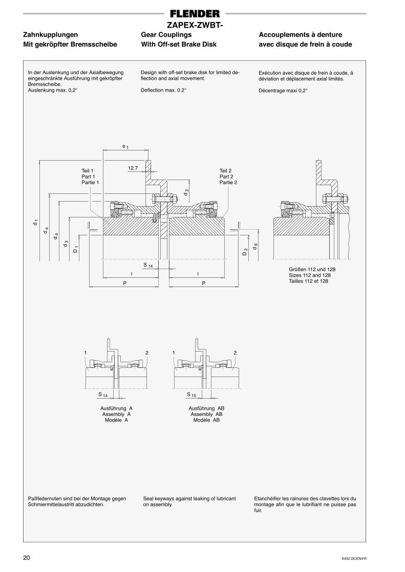
K432 DE/EN/FR20
ZAPEX-ZWBT-Zahnkupplungen Gear Couplings Accouplements à dentureMit gekröpfter Bremsscheibe With Off-set Brake Disk avec disque de frein à coude
Etanchéifier les rainures des clavettes lors dumontage afin que le lubrifiant ne puisse pasfuir.
Seal keyways against leaking of lubricanton assembly.
Paßfedernuten sind bei der Montage gegenSchmiermittelaustritt abzudichten.
Exécution avec disque de frein à coude, àdéviation et déplacement axial limités.
Décentrage maxi 0,2°
Design with off-set brake disk for limited de-flection and axial movement.
Deflection max. 0.2°
In der Auslenkung und der Axialbewegungeingeschränkte Ausführung mit gekröpfterBremsscheibe.Auslenkung max. 0,2°
D 1
P
d 3
d 4d
a
P
l l
D 2 d
6
e 1
12.7Teil 1Part 1Partie 1
Teil 2Part 2Partie 2
S 14 S 15
1 2 1 2
Größen 112 und 128Sizes 112 and 128Tailles 112 et 128
Ausführung AAssembly AModèle A
Ausführung ABAssembly ABModèle AB
d 1
S 14
d 2
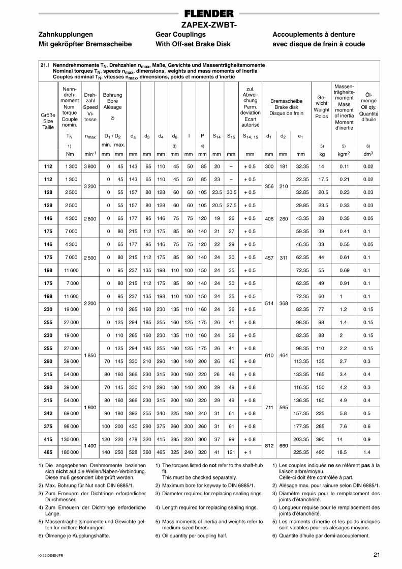
K432 DE/EN/FR 21
ZAPEX-ZWBT-Zahnkupplungen Gear Couplings Accouplements à dentureMit gekröpfter Bremsscheibe With Off-set Brake Disk avec disque de frein à coude
21.I Nenndrehmomente TN, Drehzahlen nmax, Maße, Gewichte und MassenträgheitsmomenteNominal torques TN, speeds nmax, dimensions, weights and mass moments of inertiaCouples nominal TN, vitesses nmax, dimensions, poids et moments d’inertie
GrößeSizeTaille
Nenn-dreh-
momentNom.torqueCouplenomin.
Dreh-zahl
SpeedVi-
tesse
BohrungBore
Alésage
2)
zul.Abwei-chungPerm.
deviationEcart
autorisé
BremsscheibeBrake disk
Disque de frein
Ge-wicht
WeightPoids
Massen-trägheits-moment
Massmomentof inertiaMomentd‘inertie
Öl-mengeOil qty.
Quantitéd’huile
Taille
TN nmax D1 / D2 da d3 d4 d6 l P S14 S15 S14, 15 d1 d2 e1
1) min. max. 3) 4) 5) 5) 6)
Nm min-1 mm mm mm mm mm mm mm mm mm mm mm mm mm mm kg kgm2 dm3
112 1 300 3 800 0 45 143 65 110 45 50 85 20 – + 0.5 300 181 32.35 14 0.11 0.02
112 1 3003 200
0 45 143 65 110 45 50 85 23 – + 0.5356 210
22.35 17.5 0.21 0.02
128 2 5003 200
0 55 157 80 128 60 60 105 23.5 30.5 + 0.5356 210
32.85 20.5 0.23 0.03
128 2 500 0 55 157 80 128 60 60 105 20.5 27.5 + 0.5 29.85 23.5 0.33 0.03
146 4 300 2 800 0 65 177 95 146 75 75 120 19 26 + 0.5 406 260 43.35 28 0.35 0.05
175 7 000 0 80 215 112 175 85 90 140 21 27 + 0.5 59.35 39 0.41 0.1
146 4 300 0 65 177 95 146 75 75 120 22 29 + 0.5 46.35 33 0.55 0.05
175 7 000 2 500 0 80 215 112 175 85 90 140 24 30 + 0.5 457 311 62.35 44 0.61 0.1
198 11 600 0 95 237 135 198 110 100 150 24 35 + 0.5 72.35 55 0.69 0.1
175 7 000 0 80 215 112 175 85 90 140 24 30 + 0.5 62.35 49 0.91 0.1
198 11 6002 200
0 95 237 135 198 110 100 150 24 35 + 0.5514 368
72.35 60 1 0.1
230 19 0002 200
0 110 265 160 230 135 110 160 24 36 + 0.5514 368
82.35 77 1.2 0.15
255 27 000 0 125 294 185 255 160 125 175 26 41 + 0.8 98.35 98 1.4 0.15
230 19 000 0 110 265 160 230 135 110 160 24 36 + 0.5 82.35 88 2 0.15
255 27 0001 850
0 125 294 185 255 160 125 175 26 41 + 0.8610 464
98.35 110 2.2 0.15
290 39 0001 850
70 145 330 210 290 180 140 200 26 46 + 0.8610 464
113.35 135 2.7 0.3
315 54 000 80 160 366 230 315 200 160 220 26 46 + 0.8 133.35 165 3.4 0.4
290 39 000 70 145 330 210 290 180 140 200 29 49 + 0.8 116.35 150 4.2 0.3
315 54 0001 600
80 160 366 230 315 200 160 220 29 49 + 0.8711 565
136.35 180 4.9 0.4
342 69 0001 600
90 180 392 255 340 225 180 240 31 61 + 0.8711 565
157.35 225 5.8 0.5
375 98 000 100 200 430 290 375 260 200 260 31 61 + 0.8 177.35 285 7.6 0.6
415 130 0001 400
120 220 478 320 415 285 220 300 37 99 + 0.8812 660
203.35 390 14 0.9
465 180 0001 400
140 250 528 360 465 325 240 320 41 121 + 1812 660
225.35 490 18.5 1.4
1) Die angegebenen Drehmomente beziehensich nicht auf die Wellen/Naben-Verbindung.Diese muß gesondert überprüft werden.
2) Max. Bohrung für Nut nach DIN 6885/1.
3) Zum Erneuern der Dichtringe erforderlicherDurchmesser.
4) Zum Erneuern der Dichtringe erforderlicheLänge.
5) Massenträgheitsmomente und Gewichte gel-ten für mittlere Bohrungen.
6) Ölmenge je Kupplungshälfte.
1) The torques listed do not refer to the shaft-hubfit.This must be checked separately.
2) Maximum bore for keyway to DIN 6885/1.
3) Diameter required for replacing sealing rings.
4) Length required for replacing sealing rings.
5) Mass moments of inertia and weights refer tomedium-sized bores.
6) Oil quantity per coupling half.
1) Les couples indiqués ne se réfèrent pas à laliaison arbre/moyeu.Celle-ci doit être contrôlée à part.
2) Alésage max. pour rainure selon DIN 6885/1.
3) Diamètre requis pour le remplacement desjoints d’étanchéité.
4) Longueur requise pour le remplacement desjoints d’étanchéité.
5) Les moments d’inertie et les poids indiquéssont valables pour les alésages moyens.
6) Quantité d’huile par demi-accouplement.
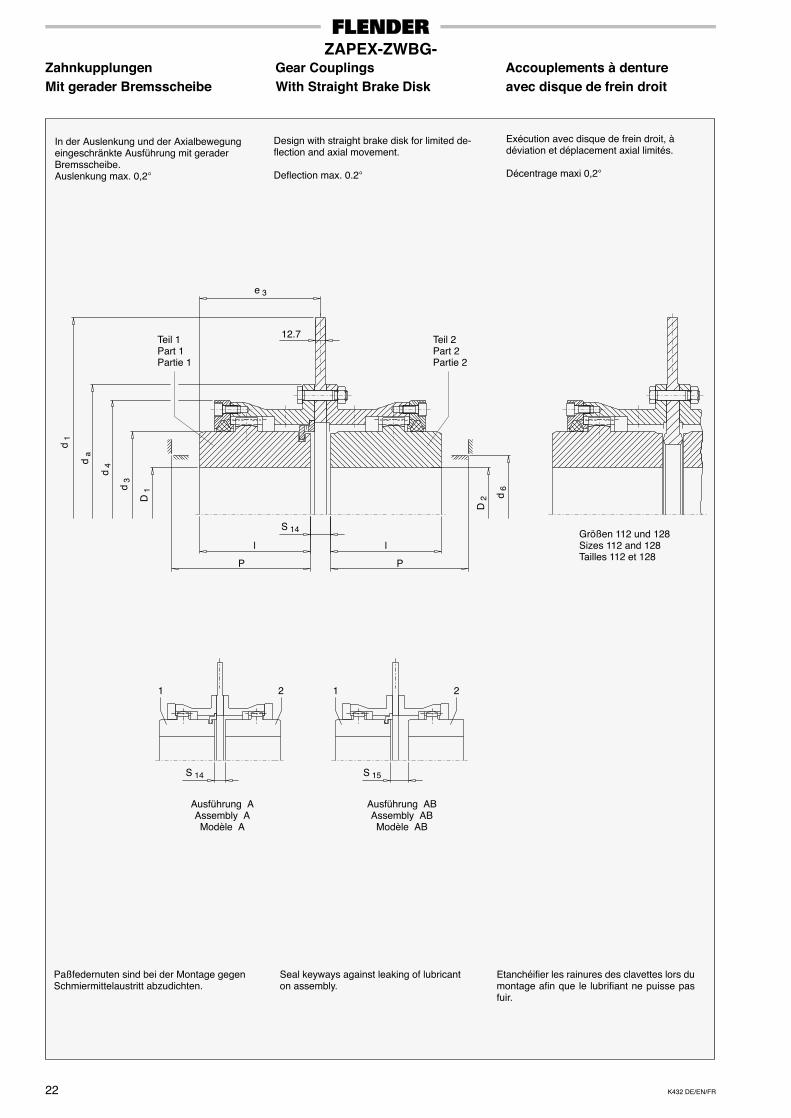
K432 DE/EN/FR22
ZAPEX-ZWBG-Zahnkupplungen Gear Couplings Accouplements à dentureMit gerader Bremsscheibe With Straight Brake Disk avec disque de frein droit
D 1
P
d 3
d 4d
a
Etanchéifier les rainures des clavettes lors dumontage afin que le lubrifiant ne puisse pasfuir.
Seal keyways against leaking of lubricanton assembly.
Paßfedernuten sind bei der Montage gegenSchmiermittelaustritt abzudichten.
l l
D 2 d
6
e 3
12.7Teil 1Part 1Partie 1
Teil 2Part 2Partie 2
S 14 S 15
1 2 1 2
Größen 112 und 128Sizes 112 and 128Tailles 112 et 128
Exécution avec disque de frein droit, àdéviation et déplacement axial limités.
Décentrage maxi 0,2°
Design with straight brake disk for limited de-flection and axial movement.
Deflection max. 0.2°
In der Auslenkung und der Axialbewegungeingeschränkte Ausführung mit geraderBremsscheibe.Auslenkung max. 0,2°
Ausführung AAssembly AModèle A
Ausführung ABAssembly ABModèle AB
d 1
S 14
P
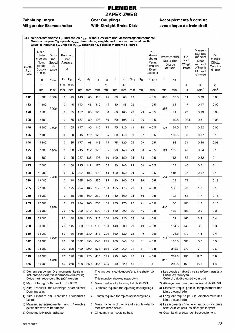
K432 DE/EN/FR 23
ZAPEX-ZWBG-Zahnkupplungen Gear Couplings Accouplements à dentureMit gerader Bremsscheibe With Straight Brake Disk avec disque de frein droit
23.I Nenndrehmomente TN, Drehzahlen nmax, Maße, Gewichte und MassenträgheitsmomenteNominal torques TN, speeds nmax, dimensions, weights and mass moments of inertiaCouples nominal TN, vitesses nmax, dimensions, poids et moments d’inertie
GrößeSizeTaille
Nenn-dreh-
momentNom.torqueCouplenomin.
Dreh-zahl
SpeedVi-
tesse
BohrungBore
Alésage
2)
zul.Abwei-chungPerm.
deviationEcart
autorisé
BremsscheibeBrake disk
Disquede frein
Ge-wicht
WeightPoids
Massen-trägheits-moment
Massmomentof inertiaMomentd‘inertie
Öl-mengeOil qty.
Quantitéd’huile
Taille
TN nmax D1 / D2 da d3 d4 d6 l P S14 S15 S14, 15 d1 e3
1) min. max. 3) 4) 5) 5) 6)
Nm min-1 mm mm mm mm mm mm mm mm mm mm mm mm mm kg kgm2 dm3
112 1 300 3 800 0 45 143 65 110 45 50 85 19 – + 0.5 300 59.5 14 0.09 0.02
112 1 3003 200
0 45 143 65 110 45 50 85 22 – + 0.5356
61 17 0.17 0.02
128 2 5003 200
0 55 157 80 128 60 60 105 22 29 + 0.5356
71 20 0.19 0.03
128 2 500 0 55 157 80 128 60 60 105 19 26 + 0.5 69.5 22.5 0.3 0.03
146 4 300 2 800 0 65 177 95 146 75 75 120 19 26 + 0.5 406 84.5 27 0.32 0.05
175 7 000 0 80 215 112 175 85 90 140 21 27 + 0.5 100.5 38 0.37 0.1
146 4 300 0 65 177 95 146 75 75 120 22 29 + 0.5 86 31 0.48 0.05
175 7 000 2 500 0 80 215 112 175 85 90 140 24 30 + 0.5 457 102 42 0.54 0.1
198 11 600 0 95 237 135 198 110 100 150 24 35 + 0.5 112 52 0.62 0.1
175 7 000 0 80 215 112 175 85 90 140 24 30 + 0.5 102 46 0.81 0.1
198 11 6002 200
0 95 237 135 198 110 100 150 24 35 + 0.5514
112 57 0.87 0.1
230 19 0002 200
0 110 265 160 230 135 110 160 24 36 + 0.5514
122 72 1 0.15
255 27 000 0 125 294 185 255 160 125 175 26 41 + 0.8 138 93 1.3 0.15
230 19 000 0 110 265 160 230 135 110 160 24 36 + 0.5 122 81 1.7 0.15
255 27 0001 850
0 125 294 185 255 160 125 175 26 41 + 0.8610
138 100 1.9 0.15
290 39 0001 850
70 145 330 210 290 180 140 200 26 46 + 0.8610
153 125 2.5 0.3
315 54 000 80 160 366 230 315 200 160 220 26 46 + 0.8 173 160 3.2 0.4
290 39 000 70 145 330 210 290 180 140 200 29 49 + 0.8 154.5 140 3.6 0.3
315 54 0001 600
80 160 366 230 315 200 160 220 29 49 + 0.8711
174.5 170 4.3 0.4
342 69 0001 600
90 180 392 255 340 225 180 240 31 61 + 0.8711
195.5 205 5.2 0.5
375 98 000 100 200 430 290 375 260 200 260 31 61 + 0.8 215.5 270 7 0.6
415 130 0001 400
120 220 478 320 415 285 220 300 37 99 + 0.8812
238.5 355 11.7 0.9
465 180 0001 400
140 250 528 360 465 325 240 320 41 121 + 1812
260.5 450 16.5 1.4
1) Die angegebenen Drehmomente beziehensich nicht auf die Wellen/Naben-Verbindung.Diese muß gesondert überprüft werden.
2) Max. Bohrung für Nut nach DIN 6885/1.
3) Zum Erneuern der Dichtringe erforderlicherDurchmesser.
4) Zum Erneuern der Dichtringe erforderlicheLänge.
5) Massenträgheitsmomente und Gewichtegelten für mittlere Bohrungen.
6) Ölmenge je Kupplungshälfte.
1) The torques listed do not refer to the shaft-hubfit.This must be checked separately.
2) Maximum bore for keyway to DIN 6885/1.
3) Diameter required for replacing sealing rings.
4) Length required for replacing sealing rings.
5) Mass moments of inertia and weights refer tomedium-sized bores.
6) Oil quantity per coupling half.
1) Les couples indiqués ne se réfèrent pas à laliaison arbre/moyeu.Celle-ci doit être contrôlée à part.
2) Alésage max. pour rainure selon DIN 6885/1.
3) Diamètre requis pour le remplacement desjoints d’étanchéité.
4) Longueur requise pour le remplacement desjoints d’étanchéité.
5) Les moments d’inertie et les poids indiquéssont valables pour les alésages moyens.
6) Quantité d’huile par demi-accouplement.
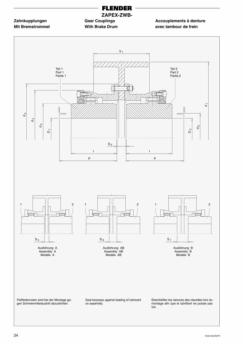
K432 DE/EN/FR24
ZAPEX-ZWB-Zahnkupplungen Gear Couplings Accouplements à dentureMit Bremstrommel With Brake Drum avec tambour de frein
D 1
P
d 3
d 4
d a
Etanchéifier les rainures des clavettes lors dumontage afin que le lubrifiant ne puisse pasfuir.
Seal keyways against leaking of lubricanton assembly.
Paßfedernuten sind bei der Montage ge-gen Schmiermittelaustritt abzudichten.
P
l l
D 2
d 6
d 1
S 5 S 6 S 7
1 2 1 2 1 2
Teil 1Part 1Partie 1
Teil 2Part 2Partie 2
b 1
Ausführung AAssembly AModèle A
Ausführung ABAssembly ABModèle AB
Ausführung BAssembly BModèle B
S 5
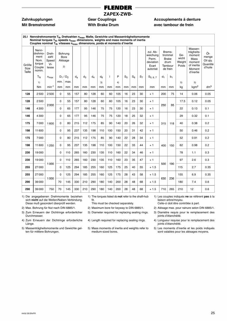
K432 DE/EN/FR 25
ZAPEX-ZWB-Zahnkupplungen Gear Couplings Accouplements à dentureMit Bremstrommel With Brake Drum avec tambour de frein
25.I Nenndrehmomente TN, Drehzahlen nmax, Maße, Gewichte und MassenträgheitsmomenteNominal torques TN, speeds nmax, dimensions, weights and mass moments of inertiaCouples nominal TN, vitesses nmax, dimensions, poids et moments d’inertie
GrößeSizeTaille
Nenn-drehmo-
mentNom.torqueCouplenomin.
Dreh-zahl
SpeedVi-
tesse
BohrungBore
Alésage
2)
zul. Ab-weichung
Perm.deviation
Ecartautorisé
Brems-trommelBrakedrum
Tambourde frein
Ge-wicht
WeightPoids
Massen-trägheits-moment
Massmomentof inertiaMomentd‘inertie
Öl-mengeOil qty.
Quantitéd’huile
Taille
TN nmax D1 / D2 da d3 d4 d6 l P S5 S6 S7 S5, 6, 7 d1 b1
1) min. max. 3) 4) 5) 5)
Nm min-1 mm mm mm mm mm mm mm mm mm mm mm mm mm mm kg kgm2 dm3
128 2 500 2 500 0 55 157 80 128 60 60 105 16 23 30 + 1 200 75 14 0.06 0.05
128 2 5002 000
0 55 157 80 128 60 60 105 16 23 30 + 1250 95
17.5 0.12 0.05
146 4 3002 000
0 65 177 95 146 75 75 120 16 23 30 + 1250 95
22 0.13 0.1
146 4 300 0 65 177 95 146 75 75 120 18 25 32 + 1 29 0.32 0.1
175 7 000 1 600 0 80 215 112 175 85 90 140 20 26 32 + 1 315 118 40 0.38 0.2
198 11 600 0 95 237 135 198 110 100 150 20 31 42 + 1 50 0.46 0.2
175 7 000 0 80 215 112 175 85 90 140 22 28 34 + 1 52 0.91 0.2
198 11 600 1 250 0 95 237 135 198 110 100 150 22 33 44 + 1 400 150 62 0.98 0.2
230 19 000 0 110 265 160 230 135 110 160 22 34 46 + 1 78 1.1 0.3
230 19 0001 000
0 110 265 160 230 135 110 160 23 35 47 + 1500 190
97 2.6 0.3
255 27 0001 000
0 125 294 185 255 160 125 175 25 40 55 + 1.5500 190
115 2.7 0.35
255 27 0001 000
0 125 294 185 255 160 125 175 28 43 58 + 1.5630 236
155 6.9 0.35
290 39 0001 000
70 145 330 210 290 180 140 200 28 48 68 + 1.5630 236
180 7.4 0.6
290 39 000 750 70 145 330 210 290 180 140 200 28 48 68 + 1.5 710 265 210 12 0.6
1) Die angegebenen Drehmomente beziehensich nicht auf die Wellen/Naben-Verbindung.Diese muß gesondert überprüft werden.
2) Max. Bohrung für Nut nach DIN 6885/1.
3) Zum Erneuern der Dichtringe erforderlicherDurchmesser.
4) Zum Erneuern der Dichtringe erforderlicheLänge.
5) Massenträgheitsmomente und Gewichte gel-ten für mittlere Bohrungen.
1) The torques listed do not refer to the shaft-hubfit.This must be checked separately.
2) Maximum bore for keyway to DIN 6885/1.
3) Diameter required for replacing sealing rings.
4) Length required for replacing sealing rings.
5) Mass moments of inertia and weights refer tomedium-sized bores.
1) Les couples indiqués ne se réfèrent pas à laliaison arbre/moyeu.Celle-ci doit être contrôlée à part.
2) Alésage max. pour rainure selon DIN 6885/1.
3) Diamètre requis pour le remplacement desjoints d’étanchéité.
4) Longueur requise pour le remplacement desjoints d’étanchéité.
5) Les moments d’inertie et les poids indiquéssont valables pour les alésages moyens.
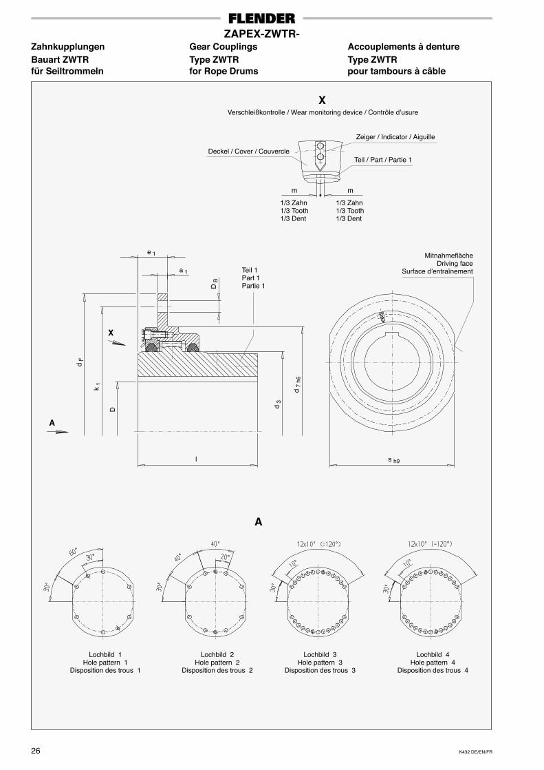
K432 DE/EN/FR26
ZAPEX-ZWTR-Zahnkupplungen Gear Couplings Accouplements à dentureBauart ZWTR Type ZWTR Type ZWTRfür Seiltrommeln for Rope Drums pour tambours à câble
D
k 1
D B
e 1
a 1
d F
d 7
h6
d 3
X
X
l
Deckel / Cover / Couvercle
Zeiger / Indicator / Aiguille
Teil / Part / Partie 1
m m
1/3 Zahn1/3 Tooth1/3 Dent
1/3 Zahn1/3 Tooth1/3 Dent
s h9
MitnahmeflächeDriving face
Surface d’entraînementTeil 1Part 1Partie 1
A
Lochbild 1Hole pattern 1
Disposition des trous 1
Lochbild 2Hole pattern 2
Disposition des trous 2
Lochbild 3Hole pattern 3
Disposition des trous 3
Lochbild 4Hole pattern 4
Disposition des trous 4
�
A
Verschleißkontrolle / Wear monitoring device / Contrôle d’usure
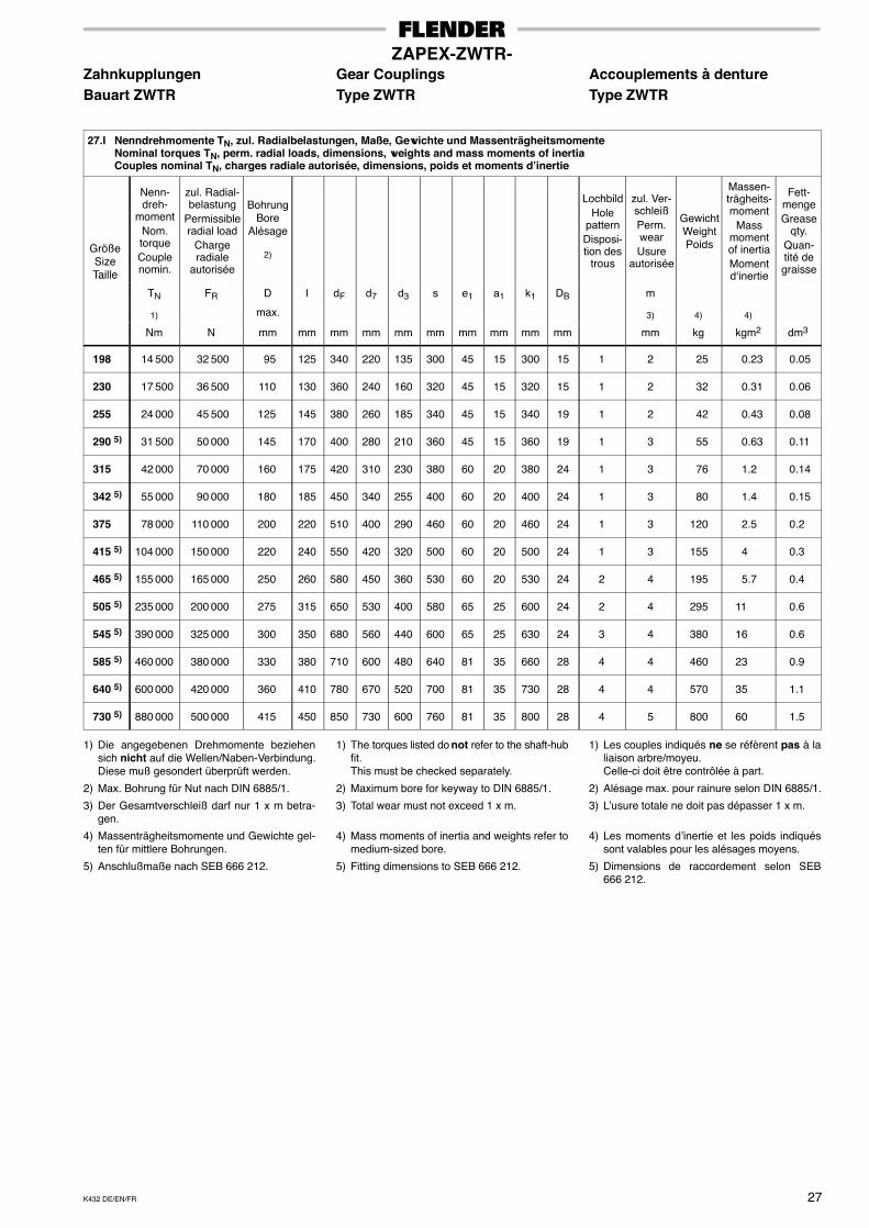
K432 DE/EN/FR 27
ZAPEX-ZWTR-Zahnkupplungen Gear Couplings Accouplements à dentureBauart ZWTR Type ZWTR Type ZWTR
27.I Nenndrehmomente TN, zul. Radialbelastungen, Maße, Gewichte und MassenträgheitsmomenteNominal torques TN, perm. radial loads, dimensions, weights and mass moments of inertiaCouples nominal TN, charges radiale autorisée, dimensions, poids et moments d’inertie
GrößeSizeTaille
Nenn-dreh-
momentNom.torqueCouplenomin.
zul. Radial-belastung
Permissibleradial load
Chargeradiale
autorisée
BohrungBore
Alésage
2)
LochbildHole
patternDisposi-tion des
trous
zul. Ver-schleißPerm.wearUsure
autorisée
GewichtWeightPoids
Massen-trägheits-moment
Massmomentof inertiaMomentd‘inertie
Fett-mengeGrease
qty.Quan-tité degraisseTaille
TN FR D l dF d7 d3 s e1 a1 k1 DB m
1) max. 3) 4) 4)
Nm N mm mm mm mm mm mm mm mm mm mm mm kg kgm2 dm3
198 14 500 32 500 95 125 340 220 135 300 45 15 300 15 1 2 25 0.23 0.05
230 17 500 36 500 110 130 360 240 160 320 45 15 320 15 1 2 32 0.31 0.06
255 24 000 45 500 125 145 380 260 185 340 45 15 340 19 1 2 42 0.43 0.08
290 5) 31 500 50 000 145 170 400 280 210 360 45 15 360 19 1 3 55 0.63 0.11
315 42 000 70 000 160 175 420 310 230 380 60 20 380 24 1 3 76 1.2 0.14
342 5) 55 000 90 000 180 185 450 340 255 400 60 20 400 24 1 3 80 1.4 0.15
375 78 000 110 000 200 220 510 400 290 460 60 20 460 24 1 3 120 2.5 0.2
415 5) 104 000 150 000 220 240 550 420 320 500 60 20 500 24 1 3 155 4 0.3
465 5) 155 000 165 000 250 260 580 450 360 530 60 20 530 24 2 4 195 5.7 0.4
505 5) 235 000 200 000 275 315 650 530 400 580 65 25 600 24 2 4 295 11 0.6
545 5) 390 000 325 000 300 350 680 560 440 600 65 25 630 24 3 4 380 16 0.6
585 5) 460 000 380 000 330 380 710 600 480 640 81 35 660 28 4 4 460 23 0.9
640 5) 600 000 420 000 360 410 780 670 520 700 81 35 730 28 4 4 570 35 1.1
730 5) 880 000 500 000 415 450 850 730 600 760 81 35 800 28 4 5 800 60 1.5
1) Die angegebenen Drehmomente beziehensich nicht auf die Wellen/Naben-Verbindung.Diese muß gesondert überprüft werden.
2) Max. Bohrung für Nut nach DIN 6885/1.
3) Der Gesamtverschleiß darf nur 1 x m betra-gen.
4) Massenträgheitsmomente und Gewichte gel-ten für mittlere Bohrungen.
5) Anschlußmaße nach SEB 666 212.
1) The torques listed do not refer to the shaft-hubfit.This must be checked separately.
2) Maximum bore for keyway to DIN 6885/1.
3) Total wear must not exceed 1 x m.
4) Mass moments of inertia and weights refer tomedium-sized bore.
5) Fitting dimensions to SEB 666 212.
1) Les couples indiqués ne se réfèrent pas à laliaison arbre/moyeu.Celle-ci doit être contrôlée à part.
2) Alésage max. pour rainure selon DIN 6885/1.
3) L’usure totale ne doit pas dépasser 1 x m.
4) Les moments d’inertie et les poids indiquéssont valables pour les alésages moyens.
5) Dimensions de raccordement selon SEB666 212.
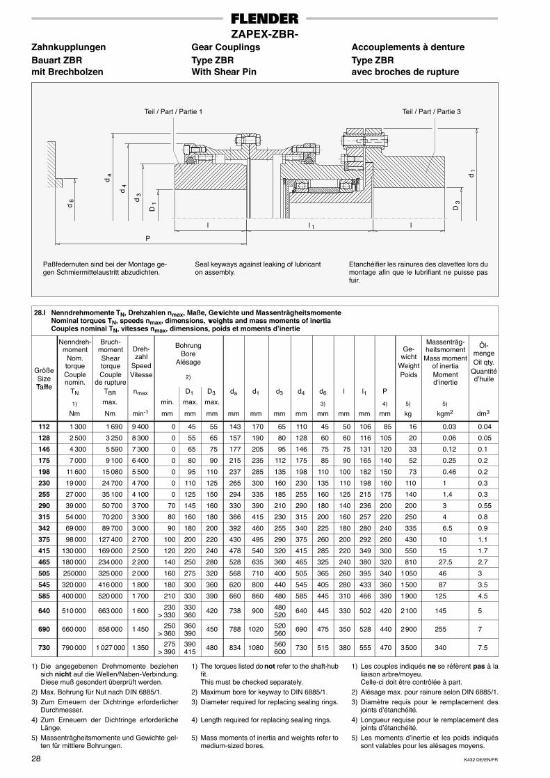
K432 DE/EN/FR28
ZAPEX-ZBR-Zahnkupplungen Gear Couplings Accouplements à dentureBauart ZBR Type ZBR Type ZBRmit Brechbolzen With Shear Pin avec broches de rupture
Etanchéifier les rainures des clavettes lors dumontage afin que le lubrifiant ne puisse pasfuir.
Seal keyways against leaking of lubricanton assembly.
Paßfedernuten sind bei der Montage ge-gen Schmiermittelaustritt abzudichten.
D 1
l
d 3
d 4
d a
d 6
D 3
d 1
l
P
Teil / Part / Partie 1 Teil / Part / Partie 3
l 1
28.I Nenndrehmomente TN, Drehzahlen nmax, Maße, Gewichte und MassenträgheitsmomenteNominal torques TN, speeds nmax, dimensions, weights and mass moments of inertiaCouples nominal TN, vitesses nmax, dimensions, poids et moments d’inertie
GrößeSizeTaille
Nenndreh-moment
Nom.torqueCouplenomin.
Bruch-momentSheartorqueCouple
de rupture
Dreh-zahl
SpeedVitesse
BohrungBore
Alésage
2)
Ge-wicht
WeightPoids
Massenträg-heitsmoment
Mass momentof inertiaMomentd‘inertie
Öl-mengeOil qty.
Quantitéd’huile
TailleTN TBR nmax D1 D3 da d1 d3 d4 d6 l l1 P
1) max. min. max. max. 3) 4) 5) 5)
Nm Nm min-1 mm mm mm mm mm mm mm mm mm mm mm kg kgm2 dm3
112 1 300 1 690 9 400 0 45 55 143 170 65 110 45 50 106 85 16 0.03 0.04
128 2 500 3 250 8 300 0 55 65 157 190 80 128 60 60 116 105 20 0.06 0.05
146 4 300 5 590 7 300 0 65 75 177 205 95 146 75 75 131 120 33 0.12 0.1
175 7 000 9 100 6 400 0 80 90 215 235 112 175 85 90 165 140 52 0.25 0.2
198 11 600 15 080 5 500 0 95 110 237 285 135 198 110 100 182 150 73 0.46 0.2
230 19 000 24 700 4 700 0 110 125 265 300 160 230 135 110 198 160 110 1 0.3
255 27 000 35 100 4 100 0 125 150 294 335 185 255 160 125 215 175 140 1.4 0.3
290 39 000 50 700 3 700 70 145 160 330 390 210 290 180 140 236 200 200 3 0.55
315 54 000 70 200 3 300 80 160 180 366 415 230 315 200 160 257 220 250 4 0.8
342 69 000 89 700 3 000 90 180 200 392 460 255 340 225 180 280 240 335 6.5 0.9
375 98 000 127 400 2 700 100 200 220 430 495 290 375 260 200 292 260 430 10 1.1
415 130 000 169 000 2 500 120 220 240 478 540 320 415 285 220 349 300 550 15 1.7
465 180 000 234 000 2 200 140 250 280 528 635 360 465 325 240 380 320 810 27.5 2.7
505 250000 325 000 2 000 160 275 320 568 710 400 505 365 260 395 340 1 050 46 3
545 320 000 416 000 1 800 180 300 360 620 800 440 545 405 280 433 360 1 500 87 3.5
585 400 000 520 000 1 700 210 330 390 660 860 480 585 445 310 466 390 1 900 125 4.5
640 510 000 663 000 1 600 230> 330
330360
420 738 900 480520
640 445 330 502 420 2 100 145 5
690 660 000 858 000 1 450 250> 360
360390
450 788 1020 520560
690 475 350 528 440 2 900 255 7
730 790 000 1 027 000 1 350 275> 390
390415
480 834 1080 560600
730 515 380 555 470 3 500 340 7.5
1) Die angegebenen Drehmomente beziehensich nicht auf die Wellen/Naben-Verbindung.Diese muß gesondert überprüft werden.
2) Max. Bohrung für Nut nach DIN 6885/1.3) Zum Erneuern der Dichtringe erforderlicher
Durchmesser.4) Zum Erneuern der Dichtringe erforderliche
Länge.5) Massenträgheitsmomente und Gewichte gel-
ten für mittlere Bohrungen.
1) The torques listed do not refer to the shaft-hubfit.This must be checked separately.
2) Maximum bore for keyway to DIN 6885/1.3) Diameter required for replacing sealing rings.
4) Length required for replacing sealing rings.
5) Mass moments of inertia and weights refer tomedium-sized bores.
1) Les couples indiqués ne se réfèrent pas à laliaison arbre/moyeu.Celle-ci doit être contrôlée à part.
2) Alésage max. pour rainure selon DIN 6885/1.3) Diamètre requis pour le remplacement des
joints d’étanchéité.4) Longueur requise pour le remplacement des
joints d’étanchéité.5) Les moments d’inertie et les poids indiqués
sont valables pour les alésages moyens.
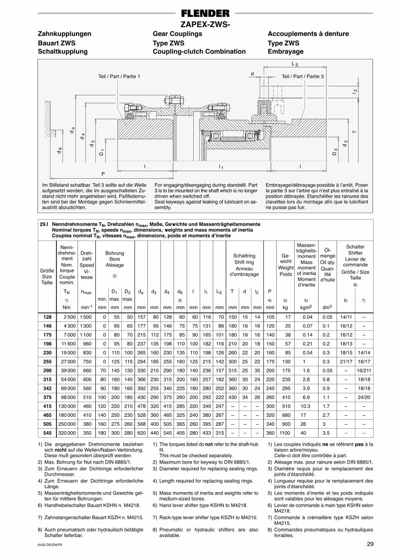
K432 DE/EN/FR 29
ZAPEX-ZWS-Zahnkupplungen Gear Couplings Accouplements à dentureBauart ZWS Type ZWS Type ZWSSchaltkupplung Coupling-clutch Combination Embrayage
Embrayage/débrayage possible à l’arrêt. Poserla partie 3 sur l’arbre qui n’est plus entraîné à laposition débrayée. Etanchéifier les rainures desclavettes lors du montage afin que le lubrifiantne puisse pas fuir.
For engaging/disengaging during standstill. Part3 is to be mounted on the shaft which is no longerdriven when switched off.Seal keyways against leaking of lubricant on as-sembly.
Im Stillstand schaltbar. Teil 3 sollte auf die Welleaufgesetzt werden, die im ausgeschalteten Zu-stand nicht mehr angetrieben wird. Paßfedernu-ten sind bei der Montage gegen Schmiermittel-austritt abzudichten.
D 1
l
d 3
d 4d
a
d 6
D 3
d 3
l
P
Teil / Part / Partie 1 Teil / Part / Partie 3
l 1
Tl 2
L S
d
29.I Nenndrehmomente TN, Drehzahlen nmax, Maße, Gewichte und MassenträgheitsmomenteNominal torques TN, speeds nmax, dimensions, weights and mass moments of inertiaCouples nominal TN, vitesses nmax, dimensions, poids et moments d’inertie
GrößeSizeTaille
Nenn-drehmo-
mentNom.torqueCouplenomin.
Dreh-zahl
SpeedVi-
tesse
BohrungBore
Alésage
2)
SchaltringShift ringAnneau
d’embrayage
Ge-wicht
WeightPoids
Massen-trägheits-moment
Massmomentof inertiaMomentd‘inertie
Öl-mengeOil qty.Quan-
titéd’huile
SchalterShifter
Levier decommande
Größe / SizeTaille
8)
TN nmax D1 D3 da d3 d4 d6 l l1 LS T d l2 P
1) min. max. max. 3) 4) 5) 5) 6) 7)
Nm min-1 mm mm mm mm mm mm mm mm mm mm mm mm mm mm kg kgm2 dm3
128 2 500 1 500 0 55 50 157 80 128 60 60 116 70 150 15 14 105 17 0.04 0.05 14/11 –
146 4 300 1 300 0 65 60 177 95 146 75 75 131 86 180 16 16 120 25 0.07 0.1 16/12 –
175 7 000 1 100 0 80 70 215 112 175 85 90 165 101 180 16 16 140 38 0.14 0.2 16/12 –
198 11 600 960 0 95 80 237 135 198 110 100 182 116 210 20 18 150 57 0.21 0.2 18/13 –
230 19 000 830 0 110 100 265 160 230 135 110 198 126 260 22 20 160 85 0.54 0.3 18/15 14/14
255 27 000 750 0 125 115 294 185 255 160 125 215 142 300 25 22 175 130 1 0.3 21/17 16/17
290 39 000 660 70 145 130 330 210 290 180 140 236 157 315 25 35 200 175 1.6 0.55 – 16/211
315 54 000 600 80 160 140 366 230 315 200 160 257 182 360 30 24 220 235 2.8 0.8 – 18/18
342 69 000 560 90 180 160 392 255 340 225 180 280 202 360 30 24 240 295 3.9 0.9 – 18/18
375 98 000 510 100 200 180 430 290 375 260 200 292 222 430 34 26 260 410 6.9 1.1 – 24/20
415 130 000 460 120 220 210 478 320 415 285 220 349 247 – – – 300 510 10.3 1.7 – –
465 180 000 410 140 250 230 528 360 465 325 240 380 267 – – – 320 680 17 2.7 – –
505 250 000 380 160 275 260 568 400 505 365 260 395 287 – – – 340 900 26 3 – –
545 320 000 350 180 300 280 620 440 545 405 280 433 315 – – – 360 1100 40 3.5 – –
1) Die angegebenen Drehmomente beziehensich nicht auf die Wellen/Naben-Verbindung.Diese muß gesondert überprüft werden.
2) Max. Bohrung für Nut nach DIN 6885/1.3) Zum Erneuern der Dichtringe erforderlicher
Durchmesser.4) Zum Erneuern der Dichtringe erforderliche
Länge.5) Massenträgheitsmomente und Gewichte gel-
ten für mittlere Bohrungen.6) Handhebelschalter Bauart KSHN n. M4218.
7) Zahnstangenschalter Bauart KSZH n. M4215.
8) Auch pneumatisch oder hydraulisch betätigteSchalter lieferbar.
1) The torques listed do not refer to the shaft-hubfit.This must be checked separately.
2) Maximum bore for keyway to DIN 6885/1.3) Diameter required for replacing sealing rings.
4) Length required for replacing sealing rings.
5) Mass moments of inertia and weights refer tomedium-sized bores.
6) Hand lever shifter type KSHN to M4218.
7) Rack-type lever shifter type KSZH to M4215.
8) Pneumatic or hydraulic shifters are alsoavailable.
1) Les couples indiqués ne se réfèrent pas à laliaison arbre/moyeu.Celle-ci doit être contrôlée à part.
2) Alésage max. pour rainure selon DIN 6885/1.3) Diamètre requis pour le remplacement des
joints d’étanchéité.4) Longueur requise pour le remplacement des
joints d’étanchéité.5) Les moments d’inertie et les poids indiqués
sont valables pour les alésages moyens.6) Levier de commande à main type KSHN selon
M4218.7) Commande à crémaillère type KSZH selon
M4215.8) Commandes pneumatiques ou hydrauliques
livrables.
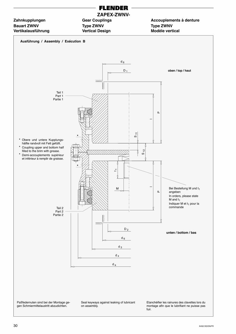
K432 DE/EN/FR30
ZAPEX-ZWNV-Zahnkupplungen Gear Couplings Accouplements à dentureBauart ZWNV Type ZWNV Type ZWNVVertikalausführung Vertical Design Modèle vertical
Teil 1Part 1
Partie 1
P
Etanchéifier les rainures des clavettes lors dumontage afin que le lubrifiant ne puisse pasfuir.
Seal keyways against leaking of lubricanton assembly.
Paßfedernuten sind bei der Montage ge-gen Schmiermittelaustritt abzudichten.
oben / top / haut
unten / bottom / bas
Ausführung / Assembly / Exécution B
Bei Bestellung M und t1angebenIn orders, please stateM and t1Indiquer M et t1 pour lacommande
d 6
D 1
D 2
d 6
d 3
d 4
d a
P
ll
S 1
1
Teil 2Part 2
Partie 2
M
t 1
S 1
2
*
*Obere und untere Kupplungs-hälfte randvoll mit Fett gefüllt.Coupling upper and bottom halffilled to the brim with grease.Demi-accouplements supérieuret inférieur à remplir de graisse.
*
*
*
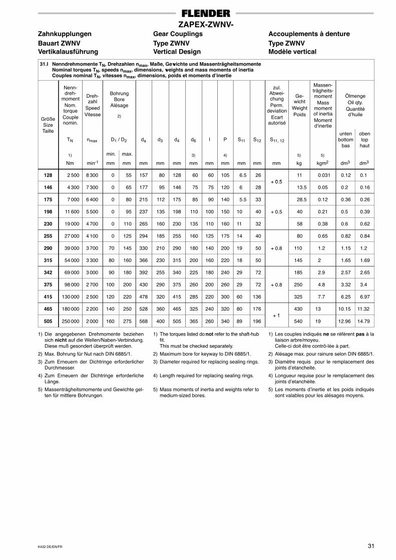
K432 DE/EN/FR 31
ZAPEX-ZWNV-Zahnkupplungen Gear Couplings Accouplements à dentureBauart ZWNV Type ZWNV Type ZWNVVertikalausführung Vertical Design Modèle vertical
31.I Nenndrehmomente TN, Drehzahlen nmax, Maße, Gewichte und MassenträgheitsmomenteNominal torques TN, speeds nmax, dimensions, weights and mass moments of inertiaCouples nominal TN, vitesses nmax, dimensions, poids et moments d’inertie
GrößeSizeT ill
Nenn-dreh-
momentNom.torqueCouplenomin.
Dreh-zahl
SpeedVitesse
BohrungBore
Alésage
2)
zul.Abwei-chungPerm.
deviationEcart
autorisé
Ge-wicht
WeightPoids
Massen-trägheits-moment
Massmomentof inertiaMomentd‘inertie
ÖlmengeOil qty.
Quantitéd’huile
Taille
TN nmax D1 / D2 da d3 d4 d6 l P S11 S12 S11, 12
untenbottom
bas
obentop
haut
1) min. max. 3) 4) 5) 5)
Nm min-1 mm mm mm mm mm mm mm mm mm mm mm kg kgm2 dm3 dm3
128 2 500 8 300 0 55 157 80 128 60 60 105 6.5 26+ 0 5
11 0.031 0.12 0.1
146 4 300 7 300 0 65 177 95 146 75 75 120 6 28+ 0.5
13.5 0.05 0.2 0.16
175 7 000 6 400 0 80 215 112 175 85 90 140 5.5 33 28.5 0.12 0.36 0.26
198 11 600 5 500 0 95 237 135 198 110 100 150 10 40 + 0.5 40 0.21 0.5 0.39
230 19 000 4 700 0 110 265 160 230 135 110 160 11 32 58 0.38 0.6 0.62
255 27 000 4 100 0 125 294 185 255 160 125 175 14 40 80 0.65 0.82 0.84
290 39 000 3 700 70 145 330 210 290 180 140 200 19 50 + 0.8 110 1.2 1.15 1.2
315 54 000 3 300 80 160 366 230 315 200 160 220 18 50 145 2 1.65 1.69
342 69 000 3 000 90 180 392 255 340 225 180 240 29 72 185 2.9 2.57 2.65
375 98 000 2 700 100 200 430 290 375 260 200 260 29 72 + 0.8 250 4.8 3.32 3.4
415 130 000 2 500 120 220 478 320 415 285 220 300 60 136 325 7.7 6.25 6.97
465 180 000 2 200 140 250 528 360 465 325 240 320 80 176+ 1
430 13 10.15 11.32
505 250 000 2 000 160 275 568 400 505 365 260 340 89 196+ 1
540 19 12.96 14.79
1) Die angegebenen Drehmomente beziehensich nicht auf die Wellen/Naben-Verbindung.Diese muß gesondert überprüft werden.
2) Max. Bohrung für Nut nach DIN 6885/1.
3) Zum Erneuern der Dichtringe erforderlicherDurchmesser.
4) Zum Erneuern der Dichtringe erforderlicheLänge.
5) Massenträgheitsmomente und Gewichte gel-ten für mittlere Bohrungen.
1) The torques listed do not refer to the shaft-hubfit.This must be checked separately.
2) Maximum bore for keyway to DIN 6885/1.
3) Diameter required for replacing sealing rings.
4) Length required for replacing sealing rings.
5) Mass moments of inertia and weights refer tomedium-sized bores.
1) Les couples indiqués ne se réfèrent pas à laliaison arbre/moyeu.Celle-ci doit être contrô-lée à part.
2) Alésage max. pour rainure selon DIN 6885/1.
3) Diamètre requis pour le remplacement desjoints d’etancheite.
4) Longueur requise pour le remplacement desjoints d’etanchéite.
5) Les moments d’inertie et les poids indiquéssont valables pour les alésages moyens.
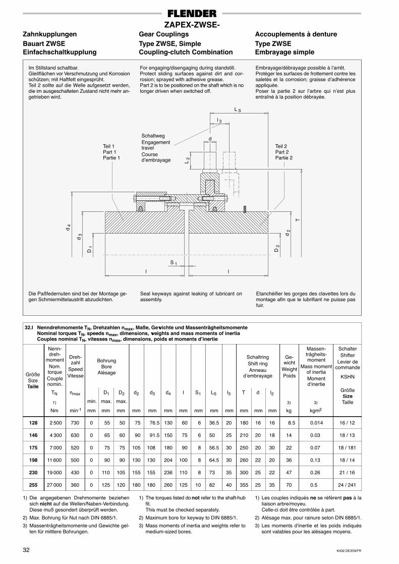
K432 DE/EN/FR32
ZAPEX-ZWSE-Zahnkupplungen Gear Couplings Accouplements à dentureBauart ZWSE Type ZWSE, Simple Type ZWSEEinfachschaltkupplung Coupling-clutch Combination Embrayage simple
Etanchéifier les gorges des clavettes lors dumontage afin que le lubrifiant ne puisse pasfuir.
Seal keyways against leaking of lubricant onassembly.
Die Paßfedernuten sind bei der Montage ge-gen Schmiermittelaustritt abzudichten.
Embrayage/débrayage possible à l’arrêt.Protéger les surfaces de frottement contre lessaletés et la corrosion; graisse d’adhérenceappliquée.Poser la partie 2 sur l’arbre qui n’est plusentraîné à la position débrayée.
For engaging/disengaging during standstill.Protect sliding surfaces against dirt and cor-rosion; sprayed with adhesive grease.Part 2 is to be positioned on the shaft which is nolonger driven when switched off.
Im Stillstand schaltbar.Gleitflächen vor Verschmutzung und Korrosionschützen; mit Haftfett eingesprüht.Teil 2 sollte auf die Welle aufgesetzt werden,die im ausgeschalteten Zustand nicht mehr an-getrieben wird.
D 1
l l
S 1
d 3
d 4
T
D 2
d 2
Teil 1Part 1Partie 1
L S
Teil 2Part 2Partie 2
l 3
d
L 2
SchaltwegEngagementtravelCoursed’embrayage
32.I Nenndrehmomente TN, Drehzahlen nmax, Maße, Gewichte und MassenträgheitsmomenteNominal torques TN, speeds nmax, dimensions, weights and mass moments of inertiaCouples nominal TN, vitesses nmax, dimensions, poids et moments d’inertie
GrößeSizeTaille
Nenn-dreh-
momentNom.torqueCouplenomin.
Dreh-zahl
SpeedVitesse
BohrungBore
Alésage
SchaltringShift ringAnneau
d’embrayage
Ge-wicht
WeightPoids
Massen-trägheits-moment
Mass momentof inertiaMomentd‘inertie
SchalterShifter
Levier decommande
KSHN
TailleTN nmax D1 D2 d2 d3 d4 l S1 LS l3 T d l2
GrößeSize
1) min. max. max. 3) 3)SizeTaille
Nm min-1 mm mm mm mm mm mm mm mm mm mm mm mm mm kg kgm2
128 2 500 730 0 55 50 75 76.5 130 60 6 36.5 20 180 16 16 8.5 0.014 16 / 12
146 4 300 630 0 65 60 90 91.5 150 75 6 50 25 210 20 18 14 0.03 18 / 13
175 7 000 520 0 75 75 105 108 180 90 8 56.5 30 250 20 30 22 0.07 18 / 181
198 11 600 500 0 90 90 130 130 204 100 8 64.5 30 260 22 20 36 0.13 18 / 14
230 19 000 430 0 110 105 155 155 236 110 8 73 35 300 25 22 47 0.26 21 / 16
255 27 000 360 0 125 120 180 180 260 125 10 82 40 355 25 35 70 0.5 24 / 241
1) Die angegebenen Drehmomente beziehensich nicht auf die Wellen/Naben-Verbindung.Diese muß gesondert überprüft werden.
2) Max. Bohrung für Nut nach DIN 6885/1.
3) Massenträgheitsmomente und Gewichte gel-ten für mittlere Bohrungen.
1) The torques listed do not refer to the shaft-hubfit.This must be checked separately.
2) Maximum bore for keyway to DIN 6885/1.
3) Mass moments of inertia and weights refer tomedium-sized bores.
1) Les couples indiqués ne se réfèrent pas à laliaison arbre/moyeu.Celle-ci doit être contrôlée à part.
2) Alésage max. pour rainure selon DIN 6885/1.
3) Les moments d’inertie et les poids indiquéssont valables pour les alésages moyens.
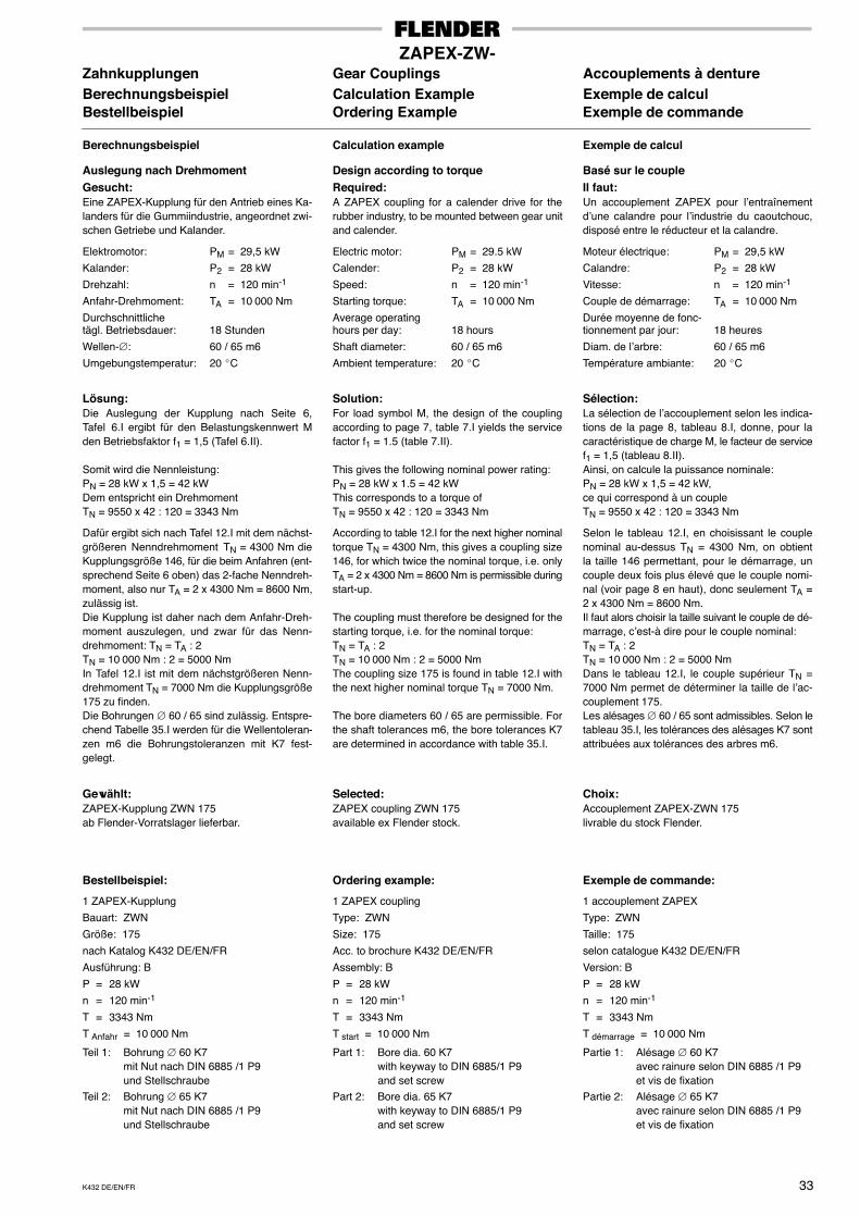
K432 DE/EN/FR 33
ZAPEX-ZW-Zahnkupplungen Gear Couplings Accouplements à dentureBerechnungsbeispiel Calculation Example Exemple de calculBestellbeispiel Ordering Example Exemple de commande
Berechnungsbeispiel
Auslegung nach DrehmomentGesucht:Eine ZAPEX-Kupplung für den Antrieb eines Ka-landers für die Gummiindustrie, angeordnet zwi-schen Getriebe und Kalander.
Elektromotor: PM = 29,5 kW
Kalander: P2 = 28 kW
Drehzahl: n = 120 min-1
Anfahr-Drehmoment: TA = 10 000 Nm
Durchschnittlichetägl. Betriebsdauer: 18 Stunden
Wellen-∅: 60 / 65 m6
Umgebungstemperatur: 20 �C
Lösung:Die Auslegung der Kupplung nach Seite 6,Tafel 6.I ergibt für den Belastungskennwert Mden Betriebsfaktor f1 = 1,5 (Tafel 6.II).
Somit wird die Nennleistung:PN = 28 kW x 1,5 = 42 kWDem entspricht ein DrehmomentTN = 9550 x 42 : 120 = 3343 Nm
Dafür ergibt sich nach Tafel 12.I mit dem nächst-größeren Nenndrehmoment TN = 4300 Nm dieKupplungsgröße 146, für die beim Anfahren (ent-sprechend Seite 6 oben) das 2-fache Nenndreh-moment, also nur TA = 2 x 4300 Nm = 8600 Nm,zulässig ist.Die Kupplung ist daher nach dem Anfahr-Dreh-moment auszulegen, und zwar für das Nenn-drehmoment: TN = TA : 2TN = 10 000 Nm : 2 = 5000 NmIn Tafel 12.I ist mit dem nächstgrößeren Nenn-drehmoment TN = 7000 Nm die Kupplungsgröße175 zu finden.Die Bohrungen ∅ 60 / 65 sind zulässig. Entspre-chend Tabelle 35.I werden für die Wellentoleran-zen m6 die Bohrungstoleranzen mit K7 fest-gelegt.
Gewählt:ZAPEX-Kupplung ZWN 175ab Flender-Vorratslager lieferbar.
Bestellbeispiel:
1 ZAPEX-Kupplung
Bauart: ZWN
Größe: 175
nach Katalog K432 DE/EN/FR
Ausführung: B
P = 28 kW
n = 120 min-1
T = 3343 Nm
T Anfahr = 10 000 Nm
Teil 1: Bohrung ∅ 60 K7mit Nut nach DIN 6885 /1 P9und Stellschraube
Teil 2: Bohrung ∅ 65 K7mit Nut nach DIN 6885 /1 P9und Stellschraube
Calculation example
Design according to torqueRequired:A ZAPEX coupling for a calender drive for therubber industry, to be mounted between gear unitand calender.
Electric motor: PM = 29.5 kW
Calender: P2 = 28 kW
Speed: n = 120 min-1
Starting torque: TA = 10 000 Nm
Average operatinghours per day: 18 hours
Shaft diameter: 60 / 65 m6
Ambient temperature: 20 �C
Solution:For load symbol M, the design of the couplingaccording to page 7, table 7.I yields the servicefactor f1 = 1.5 (table 7.II).
This gives the following nominal power rating:PN = 28 kW x 1.5 = 42 kWThis corresponds to a torque ofTN = 9550 x 42 : 120 = 3343 Nm
According to table 12.I for the next higher nominaltorque TN = 4300 Nm, this gives a coupling size146, for which twice the nominal torque, i.e. onlyTA = 2 x 4300 Nm = 8600 Nm is permissible duringstart-up.
The coupling must therefore be designed for thestarting torque, i.e. for the nominal torque:TN = TA : 2TN = 10 000 Nm : 2 = 5000 NmThe coupling size 175 is found in table 12.I withthe next higher nominal torque TN = 7000 Nm.
The bore diameters 60 / 65 are permissible. Forthe shaft tolerances m6, the bore tolerances K7are determined in accordance with table 35.I.
Selected:ZAPEX coupling ZWN 175available ex Flender stock.
Ordering example:
1 ZAPEX coupling
Type: ZWN
Size: 175
Acc. to brochure K432 DE/EN/FR
Assembly: B
P = 28 kW
n = 120 min-1
T = 3343 Nm
T start = 10 000 Nm
Part 1: Bore dia. 60 K7with keyway to DIN 6885/1 P9and set screw
Part 2: Bore dia. 65 K7with keyway to DIN 6885/1 P9and set screw
Exemple de calcul
Basé sur le coupleIl faut:Un accouplement ZAPEX pour l’entraînementd’une calandre pour l’industrie du caoutchouc,disposé entre le réducteur et la calandre.
Moteur électrique: PM = 29,5 kW
Calandre: P2 = 28 kW
Vitesse: n = 120 min-1
Couple de démarrage: TA = 10 000 Nm
Durée moyenne de fonc-tionnement par jour: 18 heures
Diam. de l’arbre: 60 / 65 m6
Température ambiante: 20 �C
Sélection:La sélection de l’accouplement selon les indica-tions de la page 8, tableau 8.I, donne, pour lacaractéristique de charge M, le facteur de servicef1 = 1,5 (tableau 8.II).Ainsi, on calcule la puissance nominale:PN = 28 kW x 1,5 = 42 kW,ce qui correspond à un coupleTN = 9550 x 42 : 120 = 3343 Nm
Selon le tableau 12.I, en choisissant le couplenominal au-dessus TN = 4300 Nm, on obtientla taille 146 permettant, pour le démarrage, uncouple deux fois plus élevé que le couple nomi-nal (voir page 8 en haut), donc seulement TA =2 x 4300 Nm = 8600 Nm.Il faut alors choisir la taille suivant le couple de dé-marrage, c’est-à dire pour le couple nominal:TN = TA : 2TN = 10 000 Nm : 2 = 5000 NmDans le tableau 12.I, le couple supérieur TN =7000 Nm permet de déterminer la taille de l’ac-couplement 175.Les alésages ∅ 60 / 65 sont admissibles. Selon letableau 35.I, les tolérances des alésages K7 sontattribuées aux tolérances des arbres m6.
Choix:Accouplement ZAPEX-ZWN 175livrable du stock Flender.
Exemple de commande:
1 accouplement ZAPEX
Type: ZWN
Taille: 175
selon catalogue K432 DE/EN/FR
Version: B
P = 28 kW
n = 120 min-1
T = 3343 Nm
T démarrage = 10 000 Nm
Partie 1: Alésage ∅ 60 K7avec rainure selon DIN 6885 /1 P9et vis de fixation
Partie 2: Alésage ∅ 65 K7avec rainure selon DIN 6885 /1 P9et vis de fixation
K432 DE/EN/FR34
ZAPEX-ZW-Zahnkupplungen Gear Couplings Accouplements à dentureTechnische Hinweise für den Design Hints for the Installation Renseignements techniques surEinbau le montage
1. Anordnung der KupplungsteileDie Anordnung der Kupplungsteile auf den zuverbindenden Wellenenden ist entsprechend denAusführungen A, AB und B vorzusehen.
2. BohrungenDie den Fertigbohrungen zugeordneten Tole-ranzfelder sind der Tafel 35.I zu entnehmen.
3. BefestigungZAPEX-Kupplungen werden normalerweise mitPaßfedernuten nach DIN 6885 Teil 1 und Stell-schrauben ausgeführt. Ausführungen mit Keil-nuten nach DIN 6886, Anzug von der Naben-innenseite, sind möglich.
Für Warmaufsetzen oder Aufpressen mittelsDruckölverfahren sind detaillierte Angaben erfor-derlich.
Bei allen Kupplungsgrößen sind die Gewinde-bohrungen für die Stellschrauben oberhalb derPaßfedernut angeordnet.
4. Lagerung der WellenendenDie zu verbindenden Wellenenden sollen un-mittelbar vor und hinter der Kupplung gelagertsein.
Um ein Erneuern der Dichtringe ohne ein Ver-schieben der Maschinen zu ermöglichen, sind dieMaße P und d6 in den Tafeln 12.I bis 31.I zu be-rücksichtigen.
5. AuswuchtenAllgemein: In einer Ebene, Gütestufe Q 16 beiv ≤ 36 m/s, jedoch bei nmax = 1500 min-1, vordem Nuten.
Das Zwischenstück der Bauart ZZS wird abv = 15 m/s in zwei Ebenen, Gütestufe Q 6,3 aus-gewuchtet.
Ausgewuchtet wird nach dem Halbkeilprinzip(DIN/ISO 8821)
Nach Vereinbarung: Ist für das Betriebs- bzw.Anlagenverhalten eine feinere Wuchtgüteerforderlich, so ist dieses gesondert zu ver-einbaren. Flender empfiehlt bei Umfangs-geschwindigkeiten v > 36 m/s eine WuchtgüteQ 6,3 (oder feiner) in zwei Ebenen, jedoch beinmax = 1500 min-1, mit Fertigbohrung, vor demNuten (oder nach Angaben des Bestellers).
Soll die Auswuchtung nach dem Vollkeil-Prinzip erfolgen, ist der ausdrückliche Hin-weis erforderlich.
6. Sicherheits-VorkehrungenUmlaufende Teile müssen vom Käufer gegenunbeabsichtigtes Berühren gesichert werden(Gesetz über technische Arbeitsmittel vom 23.Oktober 1992)
Bei Lieferungen ins Ausland sind die dort gültigenSicherheitsbestimmungen zu beachten.
Achtung!Unbedingt die Anweisungen der zuge-hörigen Betriebsanleitung beachten.
1. Arrangement of the coupling partsThe arrangement of hubs and flanged sleeves onthe shaft ends to be connected must correspondto assembly A, AB or B.
2. BoresSee table 35.I for tolerance zones of finishedbores.
3. Securing the couplingZAPEX couplings are usually provided withparallel keyways acc. to DIN 6885/1 and setscrews. Designs with taper keyways acc. to DIN6886, stressed-type fastening from the inside ofthe hub, are possible.
Full details should be supplied if couplings are tobe shrunk on or mounted by hydraulic means.
In all coupling sizes, the tapped holes for the setscrews are located above the keyways.
4. Supporting the shaft endsThe shaft ends to be connected should be sup-ported in bearings directly in front of and behindthe coupling.
To permit replacement of the sealing rings withoutmoving the machines, the dimensions P and d6in tables 12.I to 31.I must be taken into consid-eration.
5. BalancingGeneral: In one plane, quality Q 16 at v ≤ 36 m/s,but at nmax = 1500 min-1 before keyseating.
The spacer of type ZZS is balanced from v = 15m/s up in two planes, quality Q 6.3.
Balancing is carried out with half parallel key(DIN/ISO 8821)
To be agreed: If operating or plant behaviourrequires a higher balancing quality, this mustbe agreed separately. For peripheral speeds ofv > 36 m/s, Flender recommends a balancingquality of Q 6.3 (or finer) in two planes, but atnmax = 1500 min-1, with finished bore, beforekeyseating (or to order specification).
If balancing is required with full parallel key,this must be expressly stated.
6. Safety precautionsRotating parts must be protected by the pur-chaser to prevent accidental contact (legislationof October 23rd 1992 on technical working equip-ment)
For products supplied to customers abroad, thesafety regulations in the country in question mustbe taken into consideration.
Caution!Always follow the correct operating in-structions.
1. Dispositions des pièces d’accouplementLa disposition des pièces d’accouplement sur lesextrémités d’arbre de liaison doit être prévue con-formément aux versions A, AB et B.
2. AlésagesSe reporter au tableau 35.I pour les tolérancesdes alésages définitifs.
3. FixationLes accouplements ZAPEX sont normalementréalisés avec des clavettes selon DIN 6885 partie1 et vis de fixation. Des configurations avec clave-tage serré selon DIN 6886 sont possibles.
Des indications détaillées sont indispensablespour les accouplements frettés à démontagehydraulique.
Quelle que soit la taille de l’accouplement, lestrous recevant les vis sont au-dessus de la rai-nure de la clavette.
4. Paliers des arbresL’accouplement doit être monté le plus prèspossible des paliers support des arbres.
Afin de permettre le remplacement des jointsd’étanchéité sans déplacer les machines, obser-ver les distances P et d6 indiquées des tableaux12.I à 31.I.
5 EquilibrageGénéralités: Suivant un plan, niveau de qualitéQ 16 pour v ≤ 36 m/s, mais avec nmax = 1500min-1, avant la réalisation des rainures.
L’équilibrage de l’espaceur du type ZZS s’effec-tue, à partir de v = 15 m/s, suivant deux plans,avec le niveau de qualité Q 6,3.
Equilibrage selon le principe des demi-clavet-tes (DIN/ISO 8821)
Selon convention: Si le comportement en ser-vice ou de l’installation exige une qualité d’équili-brage supérieure, il faut en convenir expressé-ment. Pour les vitesses circonférentielles v > 36m/s, Flender recommande la qualité d’équili-brage Q 6,3 (ou supérieure) suivant deux plans,mais avec nmax = 1500 min-1, avec l’alésage fini,avant la réalisation des rainures (ou suivant les in-dications du client).
Si l’équilibrage doit se faire selon le principede la cale entière, le client doit le spécifierexpressément.
6. PrécautionsL’acheteur s’engage à protéger les pièces rotati-ves contre tout contact accidentel (loi du 23 octo-bre 1992 relative aux moyens de travail techni-ques).
En cas de livraison à l’étranger, les consignes desécurité du pays concerné doivent être respec-tées.
Attention!Observer impérativement les instruc-tions du mode d’emploi respectif.
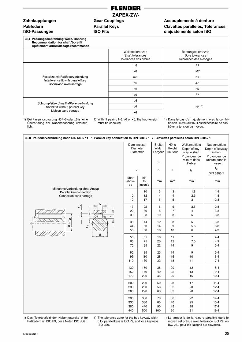
K432 DE/EN/FR 35
ZAPEX-ZW-Zahnkupplungen Gear Couplings Accouplements à denturePaßfedern Parallel Keys Clavettes parallèles, TolérancesISO-Passungen ISO Fits d’ajustements selon ISO
35.I Passungsempfehlung Welle / BohrungRecommendation for shaft / bore fitAjustement arbre / alésage recommandé
WellentoleranzenShaft tolerances
Tolérances des arbres
BohrungstoleranzenBore tolerances
Tolérances des alésages
h6 P7
k6 M7
Festsitze mit PaßfederverbindungI t f fit ith ll l k
m6 K7gInterference fit with parallel key
Connexion avec serrage n6 J7Connexion avec serrage
p6 H7
s6 F7
Schrumpfsitze ohne Paßfederverbindungu6
Schrumpfsitze ohne PaßfederverbindungShrink fit without parallel key v6 H6 1)Shrink fit without arallel key
Liaison sans serrage x6
H6
1) Bei Passungspaarung H6 / v6 oder x 6 ist eineÜberprüfung der Nabenspannung erforder-lich.
1) With fit pairing H6 / v6 or x 6, the hub tensionmust be checked.
1) Dans le cas d’un ajustement avec la combi-naison H6 / v6 ou x 6, il est nécessaire de con-trôler la tension du moyeu.
35.II Paßfederverbindung nach DIN 6885 / 1 / Parallel key connection to DIN 6885 / 1 / Clavettes parallèles selon DIN 6885 / 1
DurchmesserDiameterDiamètres
d
BreiteWidth
Largeur
1)
b
HöheHeight
Hauteur
h
WellennuttiefeDepth of key-way in shaft
Profondeur derainure dans
l’arbre
t1
NabennuttiefeDepth of keyway
in hubProfondeur derainure dans le
moyeu
t2
DIN 6885/1
Mit h bi d h A
überabove
de
bisto
jusqu’amm mm mm mm
Mitnehmerverbindung ohne AnzugParallel key connection
Connexion sans serrage
b
1012
101217
345
345
1.8 2.5
3
1.41.82.3
h
b
t 2 172230
223038
68
10
678
3.5 4 5
2.83.33.3
d +
t 2
� �
h
384450
445058
121416
89
10
5 5.5
6
3.33.84.3
d586575
657585
182022
111214
7 7.5
9
4.44.95.4
8595
110
95110130
252832
141618
91011
5.46.47.4
130150170
150170200
364045
202225
121315
8.49.4
10.4
200230260
230260290
505663
283232
172020
11.412.412.4
290330380440
330380440500
708090
100
36404550
22252831
14.415.417.419.4
1) Das Toleranzfeld der Nabennutbreite b fürPaßfedern ist ISO P9, bei 2 Nuten ISO JS9.
1) The tolerance zone for the hub keyway widthb for parallel keys is ISO P9, and for 2 keywaysISO JS9.
1) La largeur b de la rainure parallèle dans lemoyen est prévue avec tolérance ISO P9, enISO JS9 pour les liaisons à 2 clavettes.
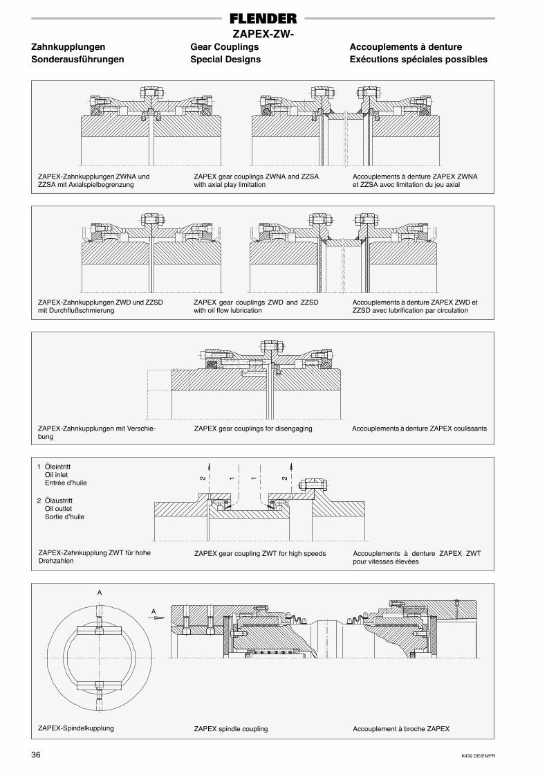
K432 DE/EN/FR36
ZAPEX-ZW-Zahnkupplungen Gear Couplings Accouplements à dentureSonderausführungen Special Designs Exécutions spéciales possibles
ZAPEX-Zahnkupplungen ZWNA undZZSA mit Axialspielbegrenzung
ZAPEX gear couplings ZWNA and ZZSAwith axial play limitation
Accouplements à denture ZAPEX ZWNAet ZZSA avec limitation du jeu axial
ZAPEX-Zahnkupplungen ZWD und ZZSDmit Durchflußschmierung
ZAPEX gear couplings ZWD and ZZSDwith oil flow lubrication
Accouplements à denture ZAPEX ZWD etZZSD avec lubrification par circulation
ZAPEX-Zahnkupplungen mit Verschie-bung
ZAPEX gear couplings for disengaging Accouplements à denture ZAPEX coulissants
ZAPEX-Zahnkupplung ZWT für hoheDrehzahlen
ZAPEX gear coupling ZWT for high speeds Accouplements à denture ZAPEX ZWTpour vitesses élevées
2 1 1 2
1 ÖleintrittOil inletEntrée d’huile
2 ÖlaustrittOil outletSortie d’huile
ZAPEX-Spindelkupplung ZAPEX spindle coupling Accouplement à broche ZAPEX
A
A
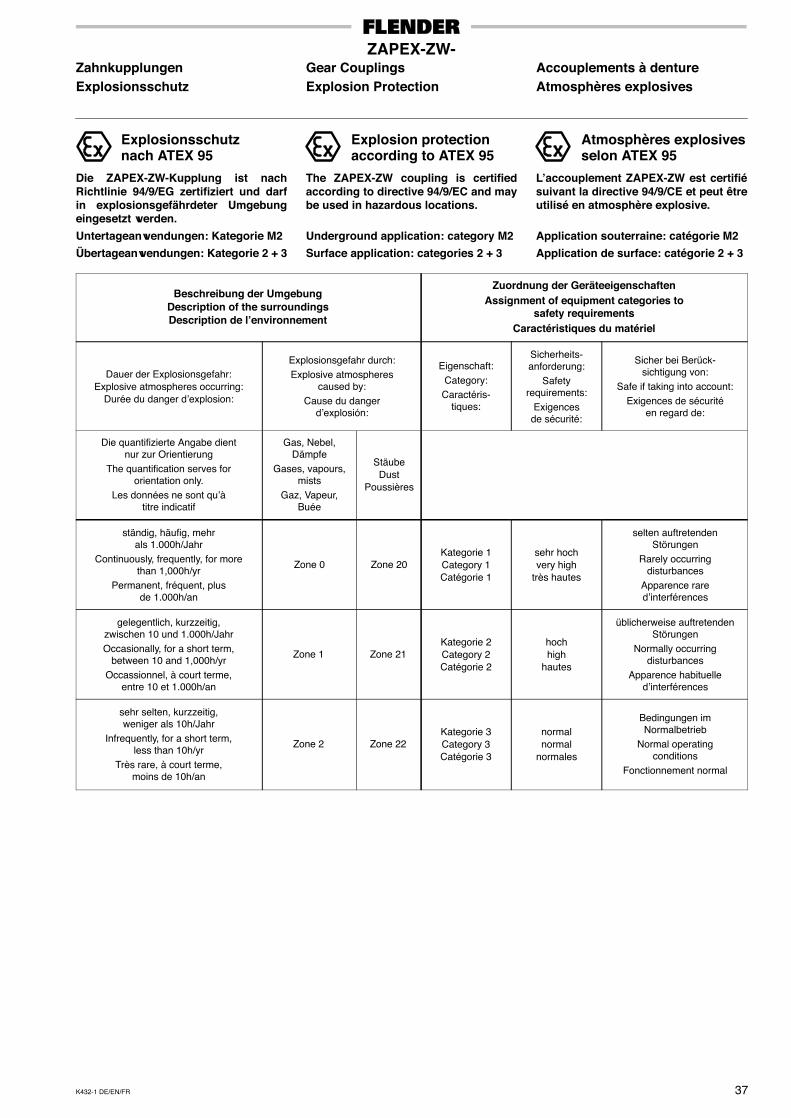
K432-1 DE/EN/FR 37
ZAPEX-ZW-Zahnkupplungen Gear Couplings Accouplements à dentureExplosionsschutz Explosion Protection Atmosphères explosives
Explosionsschutznach ATEX 95
Die ZAPEX-ZW-Kupplung ist nachRichtlinie 94/9/EG zertifiziert und darfin explosionsgefährdeter Umgebungeingesetzt werden.
Untertageanwendungen: Kategorie M2
Übertageanwendungen: Kategorie 2 + 3
Explosion protectionaccording to ATEX 95
The ZAPEX-ZW coupling is certifiedaccording to directive 94/9/EC and maybe used in hazardous locations.
Underground application: category M2
Surface application: categories 2 + 3
Atmosphères explosivesselon ATEX 95
L’accouplement ZAPEX-ZW est certifiésuivant la directive 94/9/CE et peut êtreutilisé en atmosphère explosive.
Application souterraine: catégorie M2
Application de surface: catégorie 2 + 3
Beschreibung der UmgebungDescription of the surroundingsDescription de l’environnement
Zuordnung der GeräteeigenschaftenAssignment of equipment categories to
safety requirementsCaractéristiques du matériel
Dauer der Explosionsgefahr:Explosive atmospheres occurring:
Durée du danger d’explosion:
Explosionsgefahr durch:Explosive atmospheres
caused by:Cause du danger
d’explosión:
Eigenschaft:Category:
Caractéris-tiques:
Sicherheits-anforderung:
Safetyrequirements:
Exigencesde sécurité:
Sicher bei Berück-sichtigung von:
Safe if taking into account:Exigences de sécurité
en regard de:
Die quantifizierte Angabe dientnur zur Orientierung
The quantification serves fororientation only.
Les données ne sont qu’àtitre indicatif
Gas, Nebel,Dämpfe
Gases, vapours,mists
Gaz, Vapeur,Buée
StäubeDust
Poussières
ständig, häufig, mehrals 1.000h/Jahr
Continuously, frequently, for morethan 1,000h/yr
Permanent, fréquent, plusde 1.000h/an
Zone 0 Zone 20Kategorie 1Category 1Catégorie 1
sehr hochvery high
très hautes
selten auftretendenStörungen
Rarely occurringdisturbances
Apparence rared’interférences
gelegentlich, kurzzeitig,zwischen 10 und 1.000h/JahrOccasionally, for a short term,
between 10 and 1,000h/yrOccassionnel, à court terme,
entre 10 et 1.000h/an
Zone 1 Zone 21Kategorie 2Category 2Catégorie 2
hochhigh
hautes
üblicherweise auftretendenStörungen
Normally occurringdisturbances
Apparence habituelled’interférences
sehr selten, kurzzeitig,weniger als 10h/Jahr
Infrequently, for a short term,less than 10h/yr
Très rare, à court terme,moins de 10h/an
Zone 2 Zone 22Kategorie 3Category 3Catégorie 3
normalnormal
normales
Bedingungen imNormalbetrieb
Normal operatingconditions
Fonctionnement normal

38 K432 DE/EN/FR
ZAPEX-ZW-Zahnkupplungen Gear Couplings Accouplements à dentureBemerkungen Notes Notes
.............................................................................
.............................................................................
.............................................................................
.............................................................................
.............................................................................
.............................................................................
.............................................................................
.............................................................................
.............................................................................
.............................................................................
.............................................................................
.............................................................................
.............................................................................
.............................................................................
.............................................................................
.............................................................................
.............................................................................
.............................................................................
.............................................................................
.............................................................................
.............................................................................
.............................................................................
.............................................................................
.............................................................................
.............................................................................
.............................................................................
.............................................................................
.............................................................................
.............................................................................
.............................................................................
.............................................................................
.............................................................................
.............................................................................
.............................................................................
.............................................................................
.............................................................................
.............................................................................
.............................................................................
.............................................................................
.............................................................................
.............................................................................
.............................................................................
.............................................................................
.............................................................................
.............................................................................
.............................................................................
.............................................................................
.............................................................................
.............................................................................
.............................................................................
.............................................................................
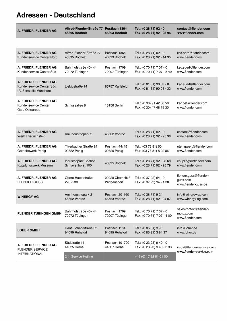
Adressen - Deutschland
A. FRIEDR. FLENDER AGAlfred-Flender-Straße 7746395 Bocholt
Postfach 136446393 Bocholt
Tel.: (0 28 71) 92 - 0Fax: (0 28 71) 92 - 25 96
A. FRIEDR. FLENDER AGKundenservice Center Nord
Alfred-Flender-Straße 7746395 Bocholt
Postfach 136446393 Bocholt
Tel.: (0 28 71) 92 - 0Fax: (0 28 71) 92 - 14 35
A. FRIEDR. FLENDER AGKundenservice Center Süd
Bahnhofstraße 40 - 4472072 Tübingen
Postfach 170972007 Tübingen
Tel.: (0 70 71) 7 07 - 0Fax: (0 70 71) 7 07 - 3 40
A. FRIEDR. FLENDER AGKundenservice Center Süd(Außenstelle München)
Liebigstraße 14 85757 KarlsfeldTel.: (0 81 31) 90 03 - 0Fax: (0 81 31) 90 03 - 33
A. FRIEDR. FLENDER AGKundenservice CenterOst / Osteuropa
Schlossallee 8 13156 BerlinTel.: (0 30) 91 42 50 58Fax: (0 30) 47 48 79 30
A. FRIEDR. FLENDER AGWerk Friedrichsfeld
Am Industriepark 2 46562 VoerdeTel.: (0 28 71) 92 - 0Fax: (0 28 71) 92 - 25 96
A. FRIEDR. FLENDER AGGetriebewerk Penig
Thierbacher Straße 2409322 Penig
Postfach 44 / 4509320 Penig
Tel.: (03 73 81) 60Fax: (03 73 81) 8 02 86
A. FRIEDR. FLENDER AGKupplungswerk Mussum
Industriepark BocholtSchlavenhorst 100
46395 BocholtTel.: (0 28 71) 92 - 28 68Fax: (0 28 71) 92 - 25 79
A. FRIEDR. FLENDER AGFLENDER GUSS
Obere Hauptstraße228 - 230
09228 Chemnitz /Wittgensdorf
Tel.: (0 37 22) 64 - 0Fax: (0 37 22) 94 - 1 38
WINERGY AGAm Industriepark 246562 Voerde
Postfach 20116046553 Voerde
Tel.: (0 28 71) 9 24Fax: (0 28 71) 92 - 24 87
FLENDER TÜBINGEN GMBHBahnhofstraße 40 - 4472072 Tübingen
Postfach 170972007 Tübingen
Tel.: (0 70 71) 7 07 - 0Fax: (0 70 71) 7 07 - 4 00
LOHER GMBHHans-Loher-Straße 3294099 Ruhstorf
Postfach 116494095 Ruhstorf
Tel.: (0 85 31) 3 90Fax: (0 85 31) 3 94 37
A. FRIEDR. FLENDER AGFLENDER SERVICE
Südstraße 11144625 Herne
Postfach 10172044607 Herne
Tel.: (0 23 23) 9 40 - 0Fax: (0 23 23) 9 40 - 3 33 [email protected]
www flender-service comINTERNATIONAL
24h Service Hotline +49 (0) 17 22 81 01 00www.flender-service.com
Addresses - InternationalE U R O P E
������� Flender Ges.m.b.H.Industriezentrum Nö-SüdStrasse 4, Objekt 14Postfach 132
2355 Wiener Neudorf Phone: +43 (0) 22 36 - 6 45 70Fax: +43 (0) 22 36 - 6 45 70 10
����� �
� ������N.V. Flender Belge S.A. Cyriel Buyssestraat 130 1800 Vilvoorde Phone: +32 (0) 2 - 2 53 10 30
Fax: +32 (0) 2 - 2 53 09 [email protected]
������ Auto - Profi GmbH Alabin Str. 52 1000 Sofia Phone: +359 (0) 2 - 9 80 66 06Fax: +359 (0) 2 - 9 80 33 01
������� � �������
�������
����������
HUM - Naklada d.o.o. Mandroviceva 3 a 10 000 Zagreb Phone: +385 (0) 1 - 2 30 60 25Fax: +385 (0) 1 - 2 30 60 24
����� ������� A. Friedr. Flender AG Branch OfficeFibichova 218 27 601 Melnik Phone: +420 315 - 62 12 20
Fax: +420 315 - 62 12 [email protected]
������� Flender Scandinavia A/S Rugmarken 35 B 3520 Farum Phone: +45 - 70 22 60 03Fax: +45 - 44 99 16 62
�������� � �����
��������
Addinol MineralölMarketing OÜ Suur-Söjamäe 32 11 415 Tallinn
(Esthonia)Phone: +372 (0) 6 - 27 99 99Fax: +372 (0) 6 - 27 99 90
������ Flender Oy Ruosilantie 2 B 00 390 Helsinki Phone: +358 (0) 9 - 4 77 84 10Fax: +358 (0) 9 - 4 36 14 10
������ Flender S.a.r.l. Head Office3, rue Jean Monnet - B.P. 5
78 996 ElancourtCedex
Phone: +33 (0) 1 - 30 66 39 00Fax: +33 (0) 1 - 30 66 35 13
Flender S.a.r.lSales OfficeAgence de LyonParc Inopolis, Route de Vourles
69 230 Saint GenisLaval
Phone: +33 (0) 4 - 72 83 95 20Fax: +33 (0) 4 - 72 83 95 39
������ Flender-Graffenstaden SA
1, rue du Vieux Moulin
B.P. 84
67 400 Illkirch -Graffenstaden
67 402 Illkirch -Graffenstaden
Phone: +33 (0) 3 - 88 67 60 00Fax: +33 (0) 3 - 88 67 06 17
����� Flender Hellas Ltd. 2, Delfon str. 11 146 Athens Phone: +30 210 - 2 91 72 80Fax: +30 210 - 2 91 71 02
������ Wentech Kft. Bécsi Út 3 - 5 1023 Budapest Phone: +36 (0) 1 - 3 45 07 90Fax: +36 (0) 1 - 3 45 07 92
[email protected]@axelero.hu
���� Flender Cigala S.p.A.Parco Tecnologico ManzoniPalazzina GViale delle industrie, 17
20 040 Caponago (MI) Phone: +39 (0) 02 - 95 96 31Fax: +39 (0) 02 - 95 74 39 30
��� ���������� Flender Nederland B.V. Lage Brink 5 - 7Postbus 1073
7317 BD Apeldoorn7301 BH Apeldoorn
Phone: +31 (0) 55 - 5 27 50 00Fax: +31 (0) 55 - 5 21 80 11
��� ���������� Bruinhof B.V. Boterdiep 37Postbus 9607
3077 AW Rotterdam3007 AP Rotterdam
Phone: +31 (0) 10 - 4 97 08 08Fax: +31 (0) 10 - 4 82 43 50
������ Flender Scandinavia A/S Rugmarken 35 B 3520 Farum Phone: +45 - 70 22 60 03Fax: +45 - 44 99 16 62
����� A. Friedr. Flender AGBranch OfficePrzedstawicielstwo w Polsceul. Wyzwolenia 27
43 - 190 Mikolów Phone: +48 (0) 32 - 2 26 45 61Fax: +48 (0) 32 - 2 26 45 62
������ Rodamientos FEYC, S.A R. Jaime Lopes Dias, 1668 CV 1750 - 124 Lissabon Phone: +351 (0) 21 - 7 54 24 10Fax: +351 (0) 21 - 7 54 24 19
������� CN Industrial Group srl B-dul Garii Obor nr. 8 DSector 2 021 747 Bucuresti Phone: +40 (0) 21 - 2 52 98 61
Fax: +40 (0) 21 - 2 52 98 [email protected]
������ Flender OOO Tjuschina 4 - 6 191 119 St. Petersburg Phone: +7 (0) 8 12 - 3 20 90 34Fax: +7 (0) 8 12 - 3 20 90 82
������� A. Friedr. Flender AG Branch OfficeVajanského 49, P.O. Box 286 08 001 Presov Phone: +421 (0) 51 - 7 70 32 67
Fax: +421 (0) 51 - 7 70 32 [email protected]
����� Flender Ibérica S.A.Poligono Industrial SanMarcos Calle Morse, 31(Parcela D - 15)
28 906 Getafe - Madrid Phone: +34 (0) 91 - 6 83 61 86Fax: +34 (0) 91 - 6 83 46 50
������ Flender Scandinavia Äsenvägen 2 44 339 Lerum Phone: +46 (0) 302 - 1 25 90Fax: +46 (0) 302 - 1 25 56
���������� Flender AG Zeughausstr. 48 5600 Lenzburg Phone: +41 (0) 62 - 8 85 76 00Fax: +41 (0) 62 - 8 85 76 76
������
Flender Güc AktarmaSistemleri Sanayi veTicaret Ltd. Sti.
IMES Sanayi, SitesiE Blok 502, Sokak No. 22
34 776 Dudullu -Istanbul
Phone: +90 (0) 2 16 - 4 66 51 41Fax: +90 (0) 2 16 - 3 64 59 13
�������DIV-DeutscheIndustrievertretung Prospect Pobedy 44 03 057 Kiev Phone: +380 (0) 44 - 2 30 29 43
Fax: +380 (0) 44 - 2 30 29 [email protected]
������ ������ �
����
Flender PowerTransmission Ltd. Thornbury Works, Leeds Road
BradfordWest YorkshireBD3 7EB
Phone: +44 (0) 12 74 - 65 77 00Fax: +44 (0) 12 74 - 66 98 36
�������
���������
������
���������
G.P.Inzenjering d.o.o. III Bulevar 54 / 19 11 070 Novi Beograd Phone: +381 (0) 11 - 60 44 73Fax: +381 (0) 11 - 3 11 67 91
A F R I C A
����� �������
���������Flender S.a.r.l. 3, rue Jean Monnet - B.P. 5 78 996 Elancourt
CedexPhone: +33 (0) 1 - 30 66 39 00Fax: +33 (0) 1 - 30 66 35 13
���� Sons of Farid Hassanen 81 Matbaa Ahlia Street Boulac 11 221, Cairo Phone: +20 (0) 2 - 5 75 15 44Fax: +20 (0) 2 - 5 75 17 02
����� ������Flender PowerTransmission (Pty.) Ltd.
Head OfficeCnr. Furnace St. & Quality Rd.P.O. Box 131
Isando - JohannesburgIsando 1600
Phone: +27 (0) 11 - 5 71 20 00Fax: +27 (0) 11 - 3 92 24 34
Flender PowerTransmission (Pty.) Ltd.
Sales OfficesUnit 3 Marconi Park, 9 MarconiCrescent, Montague GardensP.O. Box 37 291
Cape TownChempet 7442
Phone: +27 (0) 21 - 5 51 50 03Fax: +27 (0) 21 - 5 52 38 24
Flender PowerTransmission (Pty.) Ltd.
Unit 3 Goshawk ParkFalcon Industrial EstateP.O. Box 1608
New Germany - DurbanNew Germany 3620
Phone: +27 (0) 31 - 7 05 38 92Fax: +27 (0) 31 - 7 05 38 72
Flender PowerTransmission (Pty.) Ltd.
9 Industrial Crescent, Ext. 25P.O. Box 17 609
WitbankWitbank 1035
Phone: +27 (0) 13 - 6 92 34 38Fax: +27 (0) 13 - 6 92 34 52
Flender PowerTransmission (Pty.) Ltd.
Unit 14 King Fisher Park, AltonCnr. Ceramic Curve & AluminaAllee, P.O. Box 101 995
Richards BayMeerensee 3901
Phone: +27 (0) 35 - 7 51 15 63Fax: +27 (0) 35 - 7 51 15 64
A M E R I C A
�������� Chilicote S.A. Avda. Julio A. Roca 546 C 1067 ABNBuenos Aires
Phone: +54 (0) 11 - 43 31 66 10Fax: +54 (0) 11 - 43 31 42 78
����� Flender Brasil Ltda.Head OfficeRua Quatorze, 60Cidade Industrial
32 210 - 660Contagem - MG
Phone: +55 (0) 31 - 33 69 20 00Fax: +55 (0) 31 - 33 31 18 93
Flender Brasil Ltda.Sales OfficesRua James Watt, 152conjunto 142 - Brooklin Novo
04 576 - 050São Paulo - SP
Phone: +55 (0) 11 - 55 05 99 33Fax: +55 (0) 11 - 55 05 30 10
Flender Brasil Ltda. Rua Campos Sales, 1095sala 14 - centro
14 015 - 110Ribeirão Preto - SP
Phone: +55 (0) 16 - 6 35 15 90Fax: +55 (0) 16 - 6 35 11 05
Flender Brasil Ltda.Rua da Mitra - quadra 30 - lote 16Edifício Cristal - sala 207Bairro Renascença
65 075 - 770São Luis - MA
Phone: +55 (0) 98 - 32 25 84 92Fax: +55 (0) 98 - 32 25 84 93
Flender Brasil Ltda. Rua Padre Anchieta, 1691conjunto 1110 - Bairro Bigorrilho
80 730 - 000Curitiba - PR
Phone: +55 (0) 41 - 3 36 28 49Fax: +55 (0) 41 - 3 36 28 49
Flender Brasil Ltda. Rua José Alexandre Buaiz, 160sala 1017 - Enseada do Suá
29 050 - 545Vitória - ES
Phone: +55 (0) 27 - 32 24 37 35Fax: +55 (0) 27 - 32 24 37 36
������Flender PowerTransmission Inc. 215 Shields Court, Units 4 - 6 Markham
Ontario L3R 8V2Phone: +1 (0) 9 05 - 3 05 10 21Fax: +1 (0) 9 05 - 3 05 10 23
���� � ��������
������ � �������
�������
������
Flender Cono Sur Ltda. Avda. Galvarino Gallardo 1534 Providencia, Santiago Phone: +56 (0) 2 - 2 35 32 49Fax: +56 (0) 2 - 2 64 20 25
�������A.G.P. RepresentacionesLtda.
Flender Liaison Office ColombiaAv Boyaca No. 23 A50 Bodega UA 7 - 1
Bogotá Phone: +57 (0) 1 - 5 70 63 53Fax: +57 (0) 1 - 5 70 73 35
�� ���Flender de MexicoS.A. de C.V.
Head Office17, Pte, 713 Centro 72 000 Puebla Phone: +52 (0) 2 22 - 2 37 19 00
Fax: +52 (0) 2 22 - 2 37 11 [email protected]
Flender de MexicoS.A. de C.V.
Sales OfficesLago Nargis No. 38Col. Granada
11 520 Mexico, D.F. Phone: +52 (0) 55 - 52 54 30 37Fax: +52 (0) 55 - 55 31 69 39
Flender de MexicoS.A. de C.V.
Ave. San Pedro No. 231 - 5Col. Miravalle 64 660 Monterrey, N.L. Phone: +52 (0) 81 - 83 63 82 82
Fax: +52 (0) 81 - 83 63 82 [email protected]
���� Potencia Industrial E.I.R.L. Calle Gonzales Olaechea110 - URB, La Aurora Miraflores, Lima Phone: +51 (0) 1 - 2 42 84 68
Fax: +51 (0) 1 - 2 42 08 62
��� Flender Corporation 950 Tollgate RoadP.O. Box 1449 Elgin, IL. 60 123 Phone: +1 (0) 8 47 - 9 31 19 90
Fax: +1 (0) 8 47 - 9 31 07 [email protected]
Flender Corporation Service Centers West4234 Foster Ave. Bakersfield, CA. 93 308 Phone: +1 (0) 6 61 - 3 25 44 78
Fax: +1 (0) 6 61 - 3 25 44 [email protected]
�������� F. H. Transmisiones S.A. Calle Johan Schafer o SegundaCalle, Municipio Sucre Petare, Caracas Phone: +58 (0) 2 12 - 21 52 61
Fax: +58 (0) 2 12 - 21 18 [email protected]
A S I A
��������
��� ����Flender Limited No. 2 St. George’s Gate Road
5th Floor, Hastings Kolkata - 700 022 Phone: +91 (0) 33 - 2 23 05 45Fax: +91 (0) 33 - 2 23 18 57
������� �������
�� �����
Flender Power Trans-mission (Tianjin) Co., Ltd.
Head OfficeShuanghu-Shuangchen Rd.West, Beichen EconomicDevelopment Area (BEDA)
Tianjin 300 400 Phone: +86 (0) 22 - 26 97 20 63Fax: +86 (0) 22 - 26 97 20 61
Flender Power Trans-mission (Tianjin) Co., Ltd.
Sales OfficesC - 414, Lufthansa Center50 Liangmaqiao Rd.Chaoyang District
Beijing 100 016 Phone: +86 (0) 10 - 64 62 21 51Fax: +86 (0) 10 - 64 62 21 43
Flender Power Trans-mission (Tianjin) Co., Ltd.
1101 - 1102 Harbour Ring Plaza18 Xizang Zhong Rd. Shanghai 200 001 Phone: +86 (0) 21 - 53 85 31 48
Fax: +86 (0) 21 - 53 85 31 [email protected]
Flender Power Trans-mission (Tianjin) Co., Ltd.
Rm. 1503, Jianyin Building709 Jianshedadao, Hankou Wuhan 430 015 Phone: +86 (0) 27 - 85 48 67 15
Fax: +86 (0) 27 - 85 48 68 [email protected]
Flender Power Trans-mission (Tianjin) Co., Ltd.
Rm. 2802, GuangzhouInternational Electronics Tower403 Huanshi Rd. East
Guangzhou 510 095 Phone: +86 (0) 20 - 87 32 60 42Fax: +86 (0) 20 - 87 32 60 45
Flender Power Trans-mission (Tianjin) Co., Ltd.
G - 6 / F Guoxin Mansion77 Xiyu Street Chengdu 610 015 Phone: +86 (0) 28 - 86 19 83 72
Fax: +86 (0) 28 - 86 19 88 [email protected]
Flender Power Trans-mission (Tianjin) Co., Ltd.
Rm. 3 - 705, Tower DCity Plaza Shenyang206 Nanjing Street (N)Heping District
Shenyang 110 001 Phone: +86 (0) 24 - 23 34 20 48Fax: +86 (0) 24 - 23 34 20 46
Flender Power Trans-mission (Tianjin) Co., Ltd.
Rm. 302, Shanzi Zhong DaInternational Mansion30 Southern Rd.
Xi’an 710 002 Phone: +86 (0) 29 - 87 20 32 68Fax: +86 (0) 29 - 87 20 32 04
Flender Power Trans-mission (Tianjin) Co., Ltd.
Rm. 23E, Xinhua Plaza, No. 6Renmin East Rd. Kunming 650 051 Phone: +86 (0) 871 - 3 12 43 68
Fax: +86 (0) 871 - 3 12 45 [email protected]
Flender Power Trans-mission (Tianjin) Co., Ltd.
Rm. 1007, Building A, GoldenCenter, Jincheng InternationalPlaza, No. 68 Jingsan Rd.
Zhengzhou 450 008 Phone: +86 (0) 371 - 5 38 80 85Fax: +86 (0) 371 - 5 38 80 89
Flender Power Trans-mission (Tianjin) Co., Ltd.
Rm. 908 (east), No. 188Guangzhou Rd. Nanjing 210 024 Phone: +86 (0) 25 - 83 24 25 50
Fax: +86 (0) 25 - 83 24 48 [email protected]
Flender Power Trans-mission (Tianjin) Co., Ltd.
Rm. 1408, Pearl RiverInternational Building No. 99Xinkai Rd. Xigang District
Dalian 116 011 Phone: +86 (0) 411 - 83 77 93 55Fax: +86 (0) 411 - 83 77 92 19
Flender Power Trans-mission (Tianjin) Co., Ltd.
Rm. 1401, Tianlin BuildingHunan Gold Source HotelNo. 279, Second BlockFurong Rd.
Changsha 410 007 Phone: +86 (0) 731 - 5 16 73 09Fax: +86 (0) 731 - 5 16 47 46
����� Flender LimitedHead OfficeNo. 2 St. George’s Gate Road5th Floor
HastingsKolkata - 700 022
Phone: +91 (0) 33 - 22 23 05 45Fax: +91 (0) 33 - 22 23 18 57
Flender Limited Industrial Growth CentreRakhajungle
NimpuraKharagpur - 721 302
Phone: +91 (0) 3222 - 23 33 07Fax: +91 (0) 3222 - 23 33 64
Flender LimitedEastern Regional Sales OfficeNo. 2 St. George’s Gate Road5th Floor
HastingsKolkata - 700 022
Phone: +91 (0) 33 - 22 23 05 45Fax: +91 (0) 33 - 22 23 08 30
Flender Limited Western Regional Sales OfficePlot No. 23, Sector 19 - C
VashiNavi Mumbai - 400 705
Phone: +91 (0) 22 - 27 65 72 27Fax: +91 (0) 22 - 27 65 72 28
Flender Limited Southern Regional Sales Office41 Nelson Manickam Road
AminjikaraiChennai - 600 029
Phone: +91 (0) 44 - 23 74 39 21Fax: +91 (0) 44 - 23 74 39 19
Flender LimitedNorthern Regional Sales Office302 Bhikaji Cama Bhawan11 Bhikaji Cama Palace
New Delhi - 110 066 Phone: +91 (0) 11 - 51 85 96 56Fax: +91 (0) 11 - 51 85 96 59
��������� Flender Singapore Pte. Ltd.Representative Office6 - 01 Wisma PresisiJl. Taman Aries Blok A1 No. 1
Jakarta Barat 11 620 Phone: +62 (0) 21 - 58 90 20 15Fax: +62 (0) 21 - 58 90 20 19
���� Cimaghand Co. Ltd.P.O. Box 15 745 - 493No. 13, 16th East StreetBeyhaghi Ave., Argentina Sq.
Tehran 15 156 Phone: +98 (0) 21 - 8 73 02 14Fax: +98 (0) 21 - 8 73 39 70
�����Greenshpon EngineeringWorks Ltd. Bar-Lev Industrial Park Misgav 20 179 Phone: +972 (0) 4 - 9 91 31 81
Fax: +972 (0) 4 - 9 91 34 [email protected]
����� Flender Japan Co., Ltd.WBG Marive East 21 FNakase 2 - 6Mihama-ku, Chiba-shi
Chiba 261 - 7121 Phone: +81 (0) 43 - 2 13 39 30Fax: +81 (0) 43 - 2 13 39 55
���������� KazGate GmbH Abay ave 143 480 009 Almaty Phone: +7 (0) - 32 72 - 74 09 71Fax: +7 (0) - 32 72 - 42 94 10
����� Flender Ltd.7th Fl. Dorim Bldg.1823 Bangbae - DongSeocho - Ku
Seoul 137 - 060 Phone: +82 (0) 2 - 34 78 63 37Fax: +82 (0) 2 - 34 78 63 45
������ South Gulf Company Al-Showaikh Ind. AreaP.O. Box 26229 Safat 13 123 Phone: +965 (0) - 4 82 97 15
Fax: +965 (0) - 4 82 97 [email protected]
������ Gabriel Acar & Fils s.a.r.l.Dahr-el-JamalZone Industrielle, Sin-el-FilB.P. 80 484
Beyrouth Phone: +961 (0) 1 - 49 82 72Fax: +961 (0) 1 - 49 49 71
������� Flender Singapore Pte. Ltd.Representative Office37 A - 2, Jalan PJU 1/39Dataran Prima
47301 Petaling JayaSelangor Darul Ehsan
Phone: +60 (0) 3 - 78 80 42 63Fax: +60 (0) 3 - 78 80 42 73
�������� A. Friedr. Flender AG Postfach 1364 46 393 Bocholt Phone: +49 (0) 28 71 - 92 22 59Fax: +49 (0) 28 71 - 92 15 16
���������� Flender Singapore Pte. Ltd.
Representative Office28 / F, Unit 2814, The Enter-prise Centre, 6766 Ayala Ave-nue corner, Paeso de Roxas
Makati City Phone: +63 (0) 2 - 8 49 39 93Fax: +63 (0) 2 - 8 49 39 17
������� � ����
���� � ������
���� � �����
������ � �����
Flender Güc AktarmaSistemleri Sanayi veTicaret Ltd. Sti.
Middle East Sales OfficeIMES Sanayi SitesiE Blok 502, Sokak No. 22
34 776 Dudullu -Istanbul
Phone: +90 (0) 2 16 - 4 99 66 23Fax: +90 (0) 2 16 - 3 64 59 13
����� ������ South Gulf Sands Est. Bandaria Area, Dohan Bldg.Flat 3 / 1, P.O. Box 32 150 Al-Khobar 31 952 Phone: +966 (0) 3 - 8 87 53 32
Fax: +966 (0) 3 - 8 87 53 [email protected]
�������� Flender Singapore Pte. Ltd. 13 A, Tech Park Crescent Singapore 63 7843 Phone: +65 (0) - 68 97 94 66Fax: +65 (0) - 68 97 94 11
����� Misrabi Co & Trading
Mezzeh AutostradeTransportationBuilding 4 / A, 5th FloorP.O. Box 12 450
Damascus Phone: +963 (0) 11 - 6 11 67 94Fax: +963 (0) 11 - 6 11 09 08
������ A. Friedr. Flender AGTaiwan Branch Company1 F, No. 5, Lane 240Nan Yang Street, Hsichih
Taipei Hsien 221 Phone: +886 (0) 2 - 26 93 24 41Fax: +886 (0) 2 - 26 94 36 11
������� Flender Singapore Pte. Ltd.
Representative OfficeTalay-Thong Tower, 53 Moo 910th Floor Room 1001Sukhumvit Rd., T. Tungsukla
A. SrirachaChonburi 20 230
Phone: +66 (0) 38 - 49 51 66 - 8Fax: +66 (0) 38 - 49 51 69
������� Flender Singapore Pte. Ltd.Representative OfficeSuite 22, 16 F Saigon Tower29 Le Duan Street, District 1
Ho Chi Minh City Phone: +84 (0) 8 - 8 23 62 97Fax: +84 (0) 8 - 8 23 62 88
A U S T R A L I A
Flender (Australia) Pty. Ltd.Head Office9 Nello Place, P.O. Box 6047Wetherill Park
N.S.W. 2164, Sydney Phone: +61 (0) 2 - 97 56 23 22Fax: +61 (0) 2 - 97 56 48 92
Flender (Australia) Pty. Ltd.Sales OfficesSuite 3, 261 Centre Rd.Bentleigh
VIC 3204, Melbourne Phone: +61 (0) 3 - 95 57 08 11Fax: +61 (0) 3 - 95 57 08 22
Flender (Australia) Pty. Ltd. Suite 5, 1407 Logan Rd.Mt. Gravatt QLD 4122, Brisbane Phone: +61 (0) 7 - 34 22 23 89
Fax: +61 (0) 7 - 34 22 24 [email protected]
Flender (Australia) Pty. Ltd. Suite 2403 Great Eastern Highway
W.A. 6104Redcliffe - Perth
Phone: +61 (0) 8 - 94 77 41 66Fax: +61 (0) 8 - 94 77 65 11
��� ������ Flender (Australia) Pty. Ltd. 9 Nello Place, P.O. Box 6047Wetherill Park N.S.W. 2164, Sydney Phone: +61 (0) 2 - 97 56 23 22
Fax: +61 (0) 2 - 97 56 48 [email protected]


A. Friedr. Flender AG · Alfred-Flender-Strasse 77 · 46395 BocholtPhone: +49(0)2871-920 · Fax: +49(0)2871-922596 · www.flender.comK
432
DE
/EN
/FR
200
5-06