Embed Size (px)
Citation preview

Katalog
Stand: September 2008

Verehrter Kunde,
Cleveland aus Löffingen ist seit 30 Jahren ein anerkannter Herstellervon hochwertigen Linearführungen, Positioniertischen,Linearsystemen, von Abricht- und Profiliermaschinen und Lösungenfür Sondermaschinen.
Löffingen liegt im Schwarzwald. Seit vielen Generationen wurdenin unsererUmgebungmit teilweise einfachen Mitteln sehr genaue undkomplexe Uhren hergestellt. Aus dieser Tradition schöpfen unsereMitarbeiter ihr fundiertes Fachwissen in Präzision und Qualität.
Konstruktion und Produktion der meisten Produkte bei uns im Hausegewährleisten bei kurzen Wegen schnellste Reaktion und Flexibilität,um Ihre Anforderungen passgenau in die Anwendungen zu integrieren.
In dem Ihnen nun vorliegenden Katalog finden Sie unsere bewährtenProdukte die Sie seit vielen Jahren kennen und einsetzen. Mit deraktualisierten und neu gegliederten Darstellung, sowie zusätzlichentechnischen Daten wollen wir Ihre Arbeit erleichtern. 3DCADDatenaller Produkte sowie unsere individuelle Beratung stehen Ihnen selbst-verständlich ebenfalls zur Verfügung.
Wir wünschen Ihnen viel Erfolg!
Ihr Team derCleveland Präzisions-Systeme GmbH
Dear Customer,
Cleveland from Loeffingen is an established manufacturer of high-quality linear motion and positioning systems, dressing and profilingmachines for Diamond and CBN-grinding wheels and solutions forspecial grinding machines since 30 years.
Loeffingen is located in the Black Forest. Since many generations veryexact and complex clocks were manufactured with sometimes simplemeans in our environment. From this tradition our employees acquiretheir founded know-how in precision and quality.
With in-house construction and production of nearly all productsfastest reaction and flexibility with short ways are ensured in orderto apply to your requirements to fit properly in the applications.
You will find our approved products in this now available cataloguethat you knew and used for many years. With this updated and newstructured presentation together with additional technical data wewant to make work easier for you. 3D CAD data of all products aswell as our individual support are obviously at your disposal.
We wish you good speed!
Your Team ofCleveland Präzisions Systeme GmbH
1
2
3
4
5
6
Kreuzrollengelagerte-SchlittenführungenCross Roller Bearing Slides
SO 3.01SP | SL | SM 3.04SE | SCE 3.06SZH | SZP 3.08MSP | MSM 3.09
NO 2.01NP | NL | NM 2.04NE | NCE 2.08
6.01
4.01
Seite | Page
RO 1.01RP | RL | RM 1.04ROL | ROM 1.06RE | RCE 1.08RLHE 1.10
Seite | Page
RZH | RZP 1.11RQ 1.12RQP | RQL | RQM 1.13
Nadelrollengelagerte SchlittenführungenNeedle Roller Bearing Slides
Schwalbenschwanz-SchlittenführungenDovetail Slides
SteuerungenControls
ZubehörAccessories
R 5.01N / O 5.04SE | SCE 5.06GS-N / O 5.08Techn. 5.10
FührungsschienenGuide rails
Breitewidth 30 - 300 mm 100 - 400 mm 30 - 400 mm 30 - 150 mm 150 - 400 mm
HubTravel 12 - 950 mm 50 - 800 mm 10 - 600 mm 10 - 200 mm 100 - 1200 mm
Tragzahl (Belastung) bis …Load capacity up to max. … 29.000 N 59.850 N 33.281 N 960 N 6400 N
Verfahrgeschwindigkeit bis …Travel speed up to max. … 20 m/min. 20 m/min. 15 m/min. 15 m/min. 30 m/min.
Reibungszahl (Richtwert) 0,1 mmCoefficient of friction (approx. value) 0,003 mm 0,003 mm 0,01-beschichtet / coated 0,003 mm 0,004 mm
Änderungen, die dem technischen Fortschritt dienen bleiben dem Hersteller vorbehalten.Subject to change without notice when serving technical progress.
Sämtliche im Katalog genannten Belastungsdaten sind dynamsiche WerteAll mentioned values for load capacities are dynamic values
R N S K KB / KBS
Schlittentyp Kreuzrollenschlitten Nadelrollenschlitten Schwalbenschwanzschlitten Kugelschlitten KugelbüchsenschlittenSlide type Cross roller slides Needle roller slides Dovetail slides Ball bearing slides Ball bushing slides
Technische BeschreibungTechnical Description
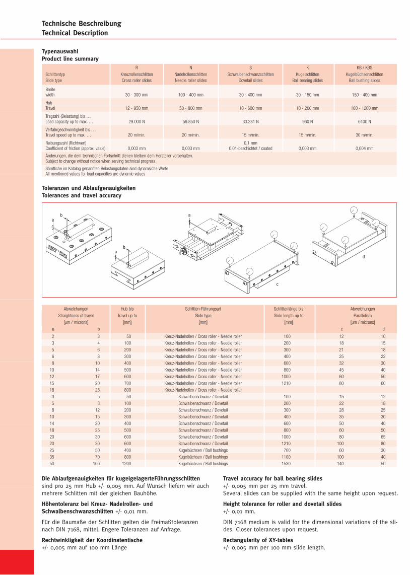
Die Ablaufgenauigkeiten für kugelgelagerteFührungsschlittensind pro 25 mm Hub +/- 0,005 mm. Auf Wunsch liefern wir auchmehrere Schlitten mit der gleichen Bauhöhe.
Höhentoleranz bei Kreuz- Nadelrollen- undSchwalbenschwanzschlitten +/- 0,01 mm.
Für die Baumaße der Schlitten gelten die Freimaßtoleranzennach DIN 7168, mittel. Engere Toleranzen auf Anfrage.
Rechtwinkligkeit der Koordinatentische+/- 0,005 mm auf 100 mm Länge
Travel accuracy for ball bearing slides+/- 0,005 mm per 25 mm travel.Several slides can be supplied with the same height upon request.
Height tolerance for roller and dovetail slides+/- 0,01 mm.
DIN 7168 medium is valid for the dimensional variations of the sli-des. Closer tolerances upon request.
Rectangularity of XY-tables+/- 0,005 mm per 100 mm slide length.
ba
ba
a
c
d
2 3 50 Kreuz-Nadelrollen / Cross roller - Needle roller 100 12 10
3 4 100 Kreuz-Nadelrollen / Cross roller - Needle roller 200 18 15
5 6 200 Kreuz-Nadelrollen / Cross roller - Needle roller 300 21 18
6 8 300 Kreuz-Nadelrollen / Cross roller - Needle roller 400 25 22
8 10 400 Kreuz-Nadelrollen / Cross roller - Needle roller 600 32 30
10 14 500 Kreuz-Nadelrollen / Cross roller - Needle roller 800 45 40
12 17 600 Kreuz-Nadelrollen / Cross roller - Needle roller 1000 60 50
15 20 700 Kreuz-Nadelrollen / Cross roller - Needle roller 1210 80 60
18 25 800 Kreuz-Nadelrollen / Cross roller - Needle roller
3 5 50 Schwalbenschwanz / Dovetail 100 15 12
5 8 100 Schwalbenschwanz / Dovetail 200 22 18
8 12 200 Schwalbenschwanz / Dovetail 300 28 25
10 15 300 Schwalbenschwanz / Dovetail 400 35 30
14 20 400 Schwalbenschwanz / Dovetail 600 50 40
18 25 500 Schwalbenschwanz / Dovetail 800 60 50
20 30 600 Schwalbenschwanz / Dovetail 1000 80 65
20 30 600 Schwalbenschwanz / Dovetail 1210 100 80
25 50 400 Kugelbüchsen / Ball bushings 700 60 30
35 70 800 Kugelbüchsen / Ball bushings 1100 100 40
50 100 1200 Kugelbüchsen / Ball bushings 1530 140 50
Abweichungen Hub bis Schlitten-Führungsart Schlittenlänge bis Abweichungen
Straightness of travel Travel up to Slide type Slide length up to Parallelism
[µm / microns] [mm] [mm] [mm] [µm / microns]
a b c d
TypenauswahlProduct line summary
Toleranzen und AblaufgenauigkeitenTolerances and travel accuracy
1
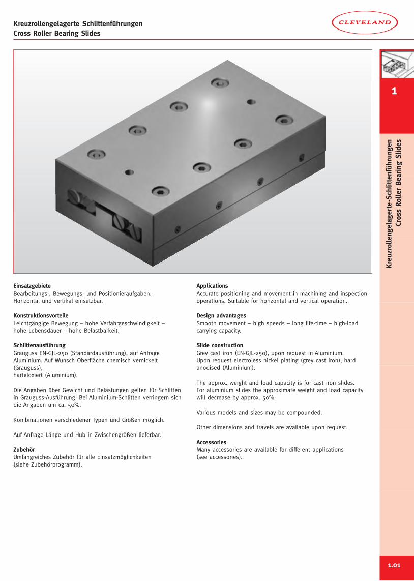
Kreuzrollengelagerte SchlittenführungenCross Roller Bearing Slides
EinsatzgebieteBearbeitungs-, Bewegungs- und Positionieraufgaben.Horizontal und vertikal einsetzbar.
KonstruktionsvorteileLeichtgängige Bewegung – hohe Verfahrgeschwindigkeit –hohe Lebensdauer – hohe Belastbarkeit.
SchlittenausführungGrauguss EN-GJL-250 (Standardausführung), auf AnfrageAluminium. Auf Wunsch Oberfläche chemisch vernickelt(Grauguss),harteloxiert (Aluminium).
Die Angaben über Gewicht und Belastungen gelten für Schlittenin Grauguss-Ausführung. Bei Aluminium-Schlitten verringern sichdie Angaben um ca. 50%.
Kombinationen verschiedener Typen und Größen möglich.
Auf Anfrage Länge und Hub in Zwischengrößen lieferbar.
ZubehörUmfangreiches Zubehör für alle Einsatzmöglichkeiten(siehe Zubehörprogramm).
ApplicationsAccurate positioning and movement in machining and inspectionoperations. Suitable for horizontal and vertical operation.
Design advantagesSmooth movement – high speeds – long life-time – high-loadcarrying capacity.
Slide constructionGrey cast iron (EN-GJL-250), upon request in Aluminium.Upon request electroless nickel plating (grey cast iron), hardanodised (Aluminium).
The approx. weight and load capacity is for cast iron slides.For aluminium slides the approximate weight and load capacitywill decrease by approx. 50%.
Various models and sizes may be compounded.
Other dimensions and travels are available upon request.
AccessoriesMany accessories are available for different applications(see accessories).
1.01
Kreuzrollengelagerte-Schlittenführungen
CrossRollerBearing
Slides
Kreuzrollengelagerte SchlittenführungenCross Roller Bearing Slides
1
1.02
Kreuzrollengelagerte-Schlittenführungen
CrossRollerBearing
Slides
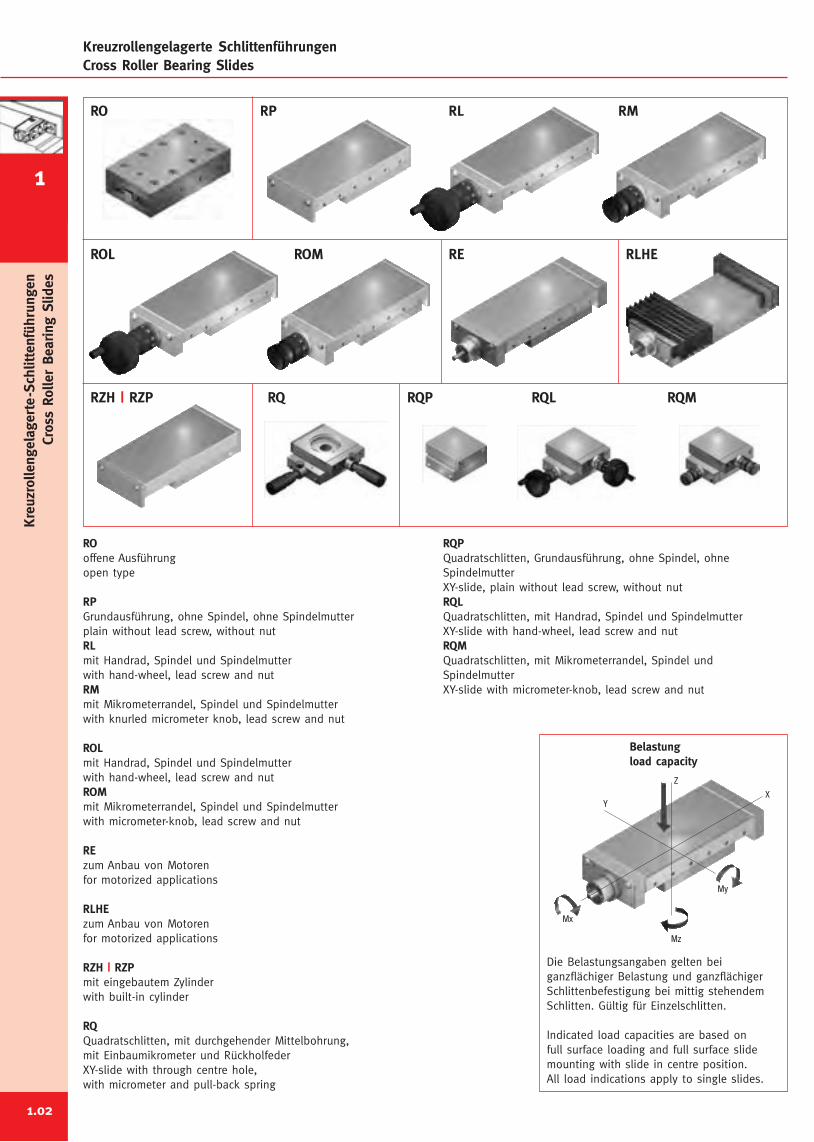
RO RP RL RM
ROL ROM RE RLHE
RQP RQMRQ RQL
ROoffene Ausführungopen type
RPGrundausführung, ohne Spindel, ohne Spindelmutterplain without lead screw, without nutRLmit Handrad, Spindel und Spindelmutterwith hand-wheel, lead screw and nutRMmit Mikrometerrandel, Spindel und Spindelmutterwith knurled micrometer knob, lead screw and nut
ROLmit Handrad, Spindel und Spindelmutterwith hand-wheel, lead screw and nutROMmit Mikrometerrandel, Spindel und Spindelmutterwith micrometer-knob, lead screw and nut
REzum Anbau von Motorenfor motorized applications
RLHEzum Anbau von Motorenfor motorized applications
RZH | RZPmit eingebautem Zylinderwith built-in cylinder
RQQuadratschlitten, mit durchgehender Mittelbohrung,mit Einbaumikrometer und RückholfederXY-slide with through centre hole,with micrometer and pull-back spring
RZH | RZP
RQPQuadratschlitten, Grundausführung, ohne Spindel, ohneSpindelmutterXY-slide, plain without lead screw, without nutRQLQuadratschlitten, mit Handrad, Spindel und SpindelmutterXY-slide with hand-wheel, lead screw and nutRQMQuadratschlitten, mit Mikrometerrandel, Spindel undSpindelmutterXY-slide with micrometer-knob, lead screw and nut
Z
Mx
Mz
My
YX
Belastungload capacity
Die Belastungsangaben gelten beiganzflächiger Belastung und ganzflächigerSchlittenbefestigung bei mittig stehendemSchlitten. Gültig für Einzelschlitten.
Indicated load capacities are based onfull surface loading and full surface slidemounting with slide in centre position.All load indications apply to single slides.
1
Kreuzrollengelagerte-Schlittenführungen
CrossRollerBearing
Slides
1
Kreuzrollengelagerte-Schlittenführungen
CrossRollerBearing
Slides
e
øf
ab
a
d
c
ba
a
a
a
b
k
G
E
øF
g
h
A
B
D
BC
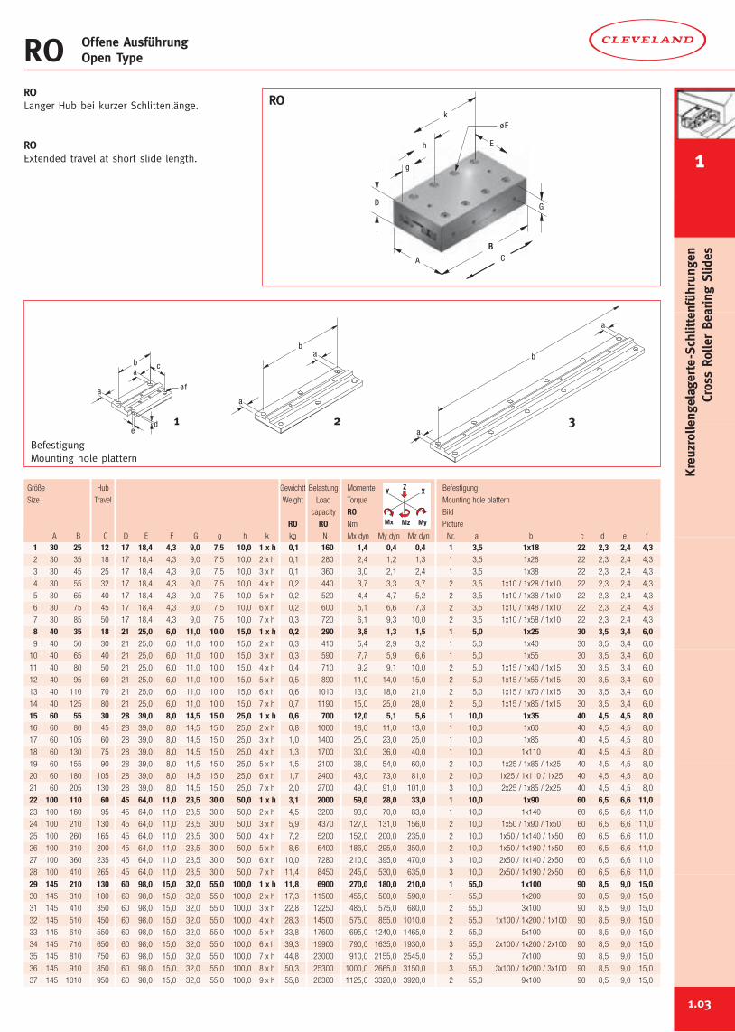
ROLanger Hub bei kurzer Schlittenlänge.
ROExtended travel at short slide length.
BefestigungMounting hole plattern
RO Offene AusführungOpen Type
RO
21 3
1.03
1 30 25 12 17 18,4 4,3 9,0 7,5 10,0 1 x h 0,1 160 1,4 0,4 0,4 1 3,5 1x18 22 2,3 2,4 4,32 30 35 18 17 18,4 4,3 9,0 7,5 10,0 2 x h 0,1 280 2,4 1,2 1,3 1 3,5 1x28 22 2,3 2,4 4,3
3 30 45 25 17 18,4 4,3 9,0 7,5 10,0 3 x h 0,1 360 3,0 2,1 2,4 1 3,5 1x38 22 2,3 2,4 4,3
4 30 55 32 17 18,4 4,3 9,0 7,5 10,0 4 x h 0,2 440 3,7 3,3 3,7 2 3,5 1x10 / 1x28 / 1x10 22 2,3 2,4 4,3
5 30 65 40 17 18,4 4,3 9,0 7,5 10,0 5 x h 0,2 520 4,4 4,7 5,2 2 3,5 1x10 / 1x38 / 1x10 22 2,3 2,4 4,3
6 30 75 45 17 18,4 4,3 9,0 7,5 10,0 6 x h 0,2 600 5,1 6,6 7,3 2 3,5 1x10 / 1x48 / 1x10 22 2,3 2,4 4,3
7 30 85 50 17 18,4 4,3 9,0 7,5 10,0 7 x h 0,3 720 6,1 9,3 10,0 2 3,5 1x10 / 1x58 / 1x10 22 2,3 2,4 4,3
8 40 35 18 21 25,0 6,0 11,0 10,0 15,0 1 x h 0,2 290 3,8 1,3 1,5 1 5,0 1x25 30 3,5 3,4 6,09 40 50 30 21 25,0 6,0 11,0 10,0 15,0 2 x h 0,3 410 5,4 2,9 3,2 1 5,0 1x40 30 3,5 3,4 6,0
10 40 65 40 21 25,0 6,0 11,0 10,0 15,0 3 x h 0,3 590 7,7 5,9 6,6 1 5,0 1x55 30 3,5 3,4 6,0
11 40 80 50 21 25,0 6,0 11,0 10,0 15,0 4 x h 0,4 710 9,2 9,1 10,0 2 5,0 1x15 / 1x40 / 1x15 30 3,5 3,4 6,0
12 40 95 60 21 25,0 6,0 11,0 10,0 15,0 5 x h 0,5 890 11,0 14,0 15,0 2 5,0 1x15 / 1x55 / 1x15 30 3,5 3,4 6,0
13 40 110 70 21 25,0 6,0 11,0 10,0 15,0 6 x h 0,6 1010 13,0 18,0 21,0 2 5,0 1x15 / 1x70 / 1x15 30 3,5 3,4 6,0
14 40 125 80 21 25,0 6,0 11,0 10,0 15,0 7 x h 0,7 1190 15,0 25,0 28,0 2 5,0 1x15 / 1x85 / 1x15 30 3,5 3,4 6,0
15 60 55 30 28 39,0 8,0 14,5 15,0 25,0 1 x h 0,6 700 12,0 5,1 5,6 1 10,0 1x35 40 4,5 4,5 8,016 60 80 45 28 39,0 8,0 14,5 15,0 25,0 2 x h 0,8 1000 18,0 11,0 13,0 1 10,0 1x60 40 4,5 4,5 8,0
17 60 105 60 28 39,0 8,0 14,5 15,0 25,0 3 x h 1,0 1400 25,0 23,0 25,0 1 10,0 1x85 40 4,5 4,5 8,0
18 60 130 75 28 39,0 8,0 14,5 15,0 25,0 4 x h 1,3 1700 30,0 36,0 40,0 1 10,0 1x110 40 4,5 4,5 8,0
19 60 155 90 28 39,0 8,0 14,5 15,0 25,0 5 x h 1,5 2100 38,0 54,0 60,0 2 10,0 1x25 / 1x85 / 1x25 40 4,5 4,5 8,0
20 60 180 105 28 39,0 8,0 14,5 15,0 25,0 6 x h 1,7 2400 43,0 73,0 81,0 2 10,0 1x25 / 1x110 / 1x25 40 4,5 4,5 8,0
21 60 205 130 28 39,0 8,0 14,5 15,0 25,0 7 x h 2,0 2700 49,0 91,0 101,0 3 10,0 2x25 / 1x85 / 2x25 40 4,5 4,5 8,0
22 100 110 60 45 64,0 11,0 23,5 30,0 50,0 1 x h 3,1 2000 59,0 28,0 33,0 1 10,0 1x90 60 6,5 6,6 11,023 100 160 95 45 64,0 11,0 23,5 30,0 50,0 2 x h 4,5 3200 93,0 70,0 83,0 1 10,0 1x140 60 6,5 6,6 11,0
24 100 210 130 45 64,0 11,0 23,5 30,0 50,0 3 x h 5,9 4370 127,0 131,0 156,0 2 10,0 1x50 / 1x90 / 1x50 60 6,5 6,6 11,0
25 100 260 165 45 64,0 11,0 23,5 30,0 50,0 4 x h 7,2 5200 152,0 200,0 235,0 2 10,0 1x50 / 1x140 / 1x50 60 6,5 6,6 11,0
26 100 310 200 45 64,0 11,0 23,5 30,0 50,0 5 x h 8,6 6400 186,0 295,0 350,0 2 10,0 1x50 / 1x190 / 1x50 60 6,5 6,6 11,0
27 100 360 235 45 64,0 11,0 23,5 30,0 50,0 6 x h 10,0 7280 210,0 395,0 470,0 3 10,0 2x50 / 1x140 / 2x50 60 6,5 6,6 11,0
28 100 410 265 45 64,0 11,0 23,5 30,0 50,0 7 x h 11,4 8450 245,0 530,0 635,0 3 10,0 2x50 / 1x190 / 2x50 60 6,5 6,6 11,0
29 145 210 130 60 98,0 15,0 32,0 55,0 100,0 1 x h 11,8 6900 270,0 180,0 210,0 1 55,0 1x100 90 8,5 9,0 15,030 145 310 180 60 98,0 15,0 32,0 55,0 100,0 2 x h 17,3 11500 455,0 500,0 590,0 1 55,0 1x200 90 8,5 9,0 15,0
31 145 410 350 60 98,0 15,0 32,0 55,0 100,0 3 x h 22,8 12250 485,0 575,0 680,0 2 55,0 3x100 90 8,5 9,0 15,0
32 145 510 450 60 98,0 15,0 32,0 55,0 100,0 4 x h 28,3 14500 575,0 855,0 1010,0 2 55,0 1x100 / 1x200 / 1x100 90 8,5 9,0 15,0
33 145 610 550 60 98,0 15,0 32,0 55,0 100,0 5 x h 33,8 17600 695,0 1240,0 1465,0 2 55,0 5x100 90 8,5 9,0 15,0
34 145 710 650 60 98,0 15,0 32,0 55,0 100,0 6 x h 39,3 19900 790,0 1635,0 1930,0 3 55,0 2x100 / 1x200 / 2x100 90 8,5 9,0 15,0
35 145 810 750 60 98,0 15,0 32,0 55,0 100,0 7 x h 44,8 23000 910,0 2155,0 2545,0 2 55,0 7x100 90 8,5 9,0 15,0
36 145 910 850 60 98,0 15,0 32,0 55,0 100,0 8 x h 50,3 25300 1000,0 2665,0 3150,0 3 55,0 3x100 / 1x200 / 3x100 90 8,5 9,0 15,0
37 145 1010 950 60 98,0 15,0 32,0 55,0 100,0 9 x h 55,8 28300 1125,0 3320,0 3920,0 2 55,0 9x100 90 8,5 9,0 15,0
Größe Hub Gewichtt Belastung Momente Befestigung
Size Travel Weight Load Torque Mounting hole plattern
capacity RO Bild
RO RO Nm Picture
A B C D E F G g h k kg N Mx dyn My dyn Mz dyn Nr. a b c d e f
Y X
MyMz
Z
Mx
1
Kreuzrollengelagerte-Schlittenführungen
CrossRollerBearing
Slides
E2
F2
K
G1
øH1
E1
F1
B
F1
B1
CA
D1
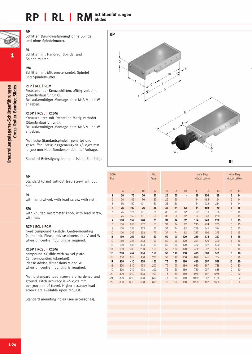
RP | RL | RM SchlittenführungenSlides
RPSchlitten (Grundausführung) ohne Spindelund ohne Spindelmutter.
RLSchlitten mit Handrad, Spindel undSpindelmutter.
RMSchlitten mit Mikrometerrandel, Spindelund Spindelmutter.
RCP | RCL | RCMFeststehender Kreuzschlitten. Mittig verbohrt(Standardausführung).Bei außermittiger Montage bitte Maß V und Wangeben.
RCSP | RCSL | RCSMKreuzschlitten mit Drehteller. Mittig verbohrt(Standardausführung).Bei außermittiger Montage bitte Maß V und Wangeben.
Metrische Standardspindeln gehärtet undgeschliffen. Steigungsgenauigkeit +/- 0,02 mmje 300 mm Hub. Sonderspindeln auf Anfrage.
Standard Befestigungsborhbild (siehe Zubehör).
RPStandard (plain) without lead screw, withoutnut.
RLwith hand-wheel, with lead screw, with nut.
RMwith knurled micrometer knob, with lead screw,with nut.
RCP | RCL | RCMfixed compound XY-slide. Centre-mounting(standard). Please advise dimensions V and Wwhen off-centre mounting is required.
RCSP | RCSL | RCSMcompound XY-slide with swivel plate.Centre-mounting (standard).Please advise dimensions V and Wwhen off-centre mounting is required.
Metric standard lead screws are hardened andground. Pitch accuracy is +/- 0,02 mmper 300 mm of travel. Higher accuracy leadscrews are available upon request.
Standard mounting holes (see accessories).
RP
RL
1 50 76 50 22 25 50 - 88 156 138 6 142 50 102 76 25 25 50 - 114 182 164 6 14
3 50 152 101 50 25 50 - 164 232 214 6 14
4 75 102 76 25 32 64 82 114 193 170 6 155 75 127 101 25 32 64 82 139 218 195 6 15
6 75 152 101 50 32 64 82 164 243 220 6 15
7 100 152 126 25 37 74 92 164 243 222 6 158 100 203 152 50 37 74 92 215 294 273 6 15
9 100 254 203 50 37 74 92 266 345 324 6 15
10 100 305 228 75 37 74 92 317 396 375 6 15
11 150 203 152 50 50 100 120 219 334 297 8 1612 150 305 203 100 50 100 120 321 436 399 8 16
13 150 406 304 100 50 100 120 422 537 500 8 16
14 150 406 253 150 50 100 120 422 537 500 8 16
15 200 457 304 150 58 116 136 473 588 551 8 1616 200 610 406 200 58 116 136 626 741 704 8 16
17 300 410 308 100 75 150 180 430 607 538 10 2018 300 610 408 200 75 150 180 630 807 738 10 20
19 300 710 408 300 75 150 180 730 907 838 10 20
20 300 910 508 400 75 150 180 930 1107 1038 10 20
21 300 1010 508 500 75 150 180 1030 1207 1138 10 20
22 300 1210 608 600 75 150 180 1230 1407 1338 10 20
Größe Hub ohne Balg ohne Balg
Size Travel without bellows without bellows
A B B1 C D1 D2 D3 E1 E2 E3 F1 F2
1.04
1
Kreuzrollengelagerte-Schlittenführungen
CrossRollerBearing
Slides
D2
W*
V*
W*
L
V*
D3
RCP RCL
RCM
RCSL
RCSM
RCSP
14 14 60,0 42,0 50 23,9 M 6 x 1 12,5 - 0,6 340 12,0 5,7 6,414 14 60,0 42,0 50 23,9 M 6 x 1 12,5 - 0,8 590 20,0 17,0 19,0
14 14 60,0 42,0 50 23,9 M 6 x 1 12,5 - 1,1 740 25,0 26,0 29,0
15 15 70,0 47,0 56 31,0 M 8 x 1 16,0 18 1,8 590 32,0 18,0 19,015 15 70,0 47,0 56 31,0 M 8 x 1 16,0 18 2,0 840 45,0 37,0 39,0
15 15 70,0 47,0 56 31,0 M 8 x 1 16,0 18 2,5 740 40,0 27,0 29,0
15 15 70,0 49,0 56* 35,0 M 12 x 1 18,0 18 4,0 1080 67,0 41,0 48,015 15 70,0 49,0 56* 35,0 M 12 x 1 18,0 18 4,7 1230 76,0 52,0 62,0
15 15 70,0 49,0 56* 35,0 M 12 x 1 18,0 18 6,1 1720 106,0 104,0 124,0
15 15 70,0 49,0 56* 35,0 M 12 x 1 18,0 18 7,0 1820 112,0 118,0 141,0
16 16 107,0 70,0 106* 48,0 M 20 x 1 24,3 20 10,0 2600 220,0 104,0 123,016 16 107,0 70,0 106* 48,0 M 20 x 1 24,3 20 13,2 3200 270,0 157,0 186,0
16 16 107,0 70,0 106* 48,0 M 20 x 1 24,3 20 18,0 5430 460,0 460,0 545,0
16 16 107,0 70,0 106* 48,0 M 20 x 1 24,3 20 16,5 3820 324,0 220,0 260,0
16 16 107,0 70,0 106* 48,0 M 20 x 1 28,3 20 30,0 5030 705,0 445,0 455,016 16 107,0 70,0 106* 48,0 M 20 x 1 28,3 20 40,0 6640 935,0 795,0 815,0
70 70 166,5 97,5 125* 68,0 Tr. 26 x 4 35,0 30 59,0 8380 3190,0 800,0 825,070 70 166,5 97,5 125* 68,0 Tr. 26 x 4 35,0 30 80,0 10370 3950,0 1205,0 1245,0
70 70 166,5 97,5 125* 68,0 Tr. 26 x 4 35,0 30 91,5 8380 3190,0 800,0 825,0
70 70 166,5 97,5 125* 68,0 Tr. 26 x 4 35,0 30 110,0 10370 3950,0 1205,0 1245,0
90 90 166,5 97,5 125* 68,0 Tr. 26 x 4 35,0 30 125,0 8380 3190,0 800,0 825,0
100 100 166,5 97,5 125* 68,0 Tr. 26 x 4 35,0 30 145,0 10370 3950,0 1205,0 1245,0
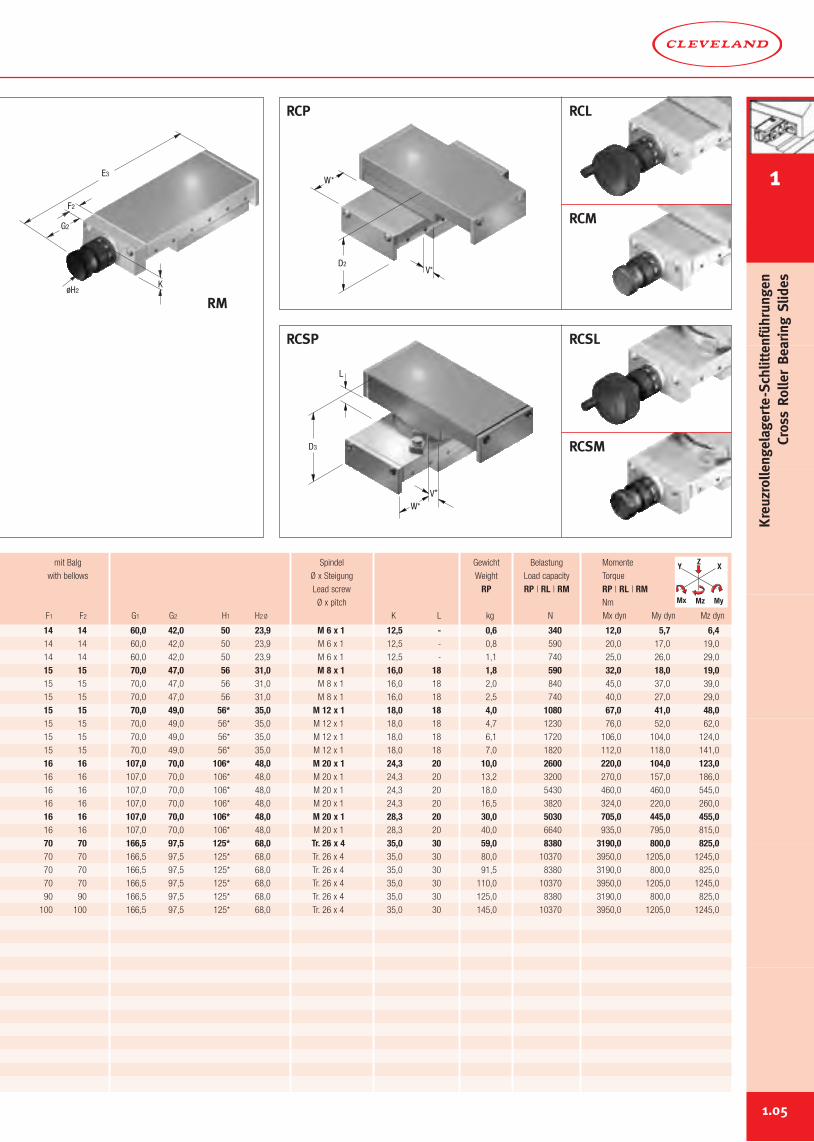
mit Balg Spindel Gewicht Belastung Momente
with bellows Ø x Steigung Weight Load capacity Torque
Lead screw RP RP | RL | RM RP | RL | RMØ x pitch Nm
F1 F2 G1 G2 H1 H2Ø K L kg N Mx dyn My dyn Mz dyn
Y X
MyMz
Z
Mx
1.05
E3
F2
K
G2
øH2
RM
1
Kreuzrollengelagerte-Schlittenführungen
CrossRollerBearing
Slides
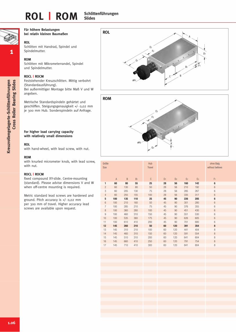
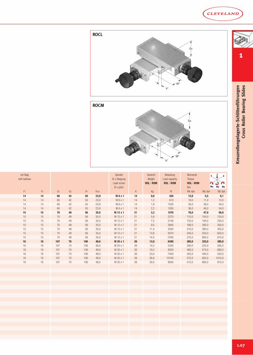
ROL | ROM SchlittenführungenSlides
Für höhere Belastungenbei relativ kleinen Baumaßen
ROLSchlitten mit Handrad, Spindel undSpindelmutter.
ROMSchlitten mit Mikrometerrandel, Spindelund Spindelmutter.
ROCL | ROCMFeststehender Kreuzschlitten. Mittig verbohrt(Standardausführung).Bei außermittiger Montage bitte Maß V und Wangeben.
Metrische Standardspindeln gehärtet undgeschliffen. Steigungsgenauigkeit +/- 0,02 mmje 300 mm Hub. Sonderspindeln auf Anfrage.
For higher load carrying capacitywith relatively small dimensions
ROLwith hand-wheel, with lead screw, with nut.
ROMwith knurled micrometer knob, with lead screw,with nut.
ROCL | ROCMfixed compound XY-slide. Centre-mounting(standard). Please advise dimensions V and Wwhen off-centre mounting is required.
Metric standard lead screws are hardened andground. Pitch accuracy is +/- 0,02 mmper 300 mm of travel. Higher accuracy leadscrews are available upon request.
1 60 80 55 25 28 56 160 142 62 60 130 80 50 28 56 210 192 6
3 60 205 130 75 28 56 285 267 6
4 60 255 155 100 28 56 335 317 6
5 100 135 110 25 45 90 226 205 66 100 210 160 50 45 90 301 280 6
7 100 285 210 75 45 90 376 355 6
8 100 360 260 100 45 90 451 430 6
9 100 460 310 150 45 90 551 530 6
10 100 535 360 175 45 90 626 605 6
11 100 610 410 200 45 90 701 680 6
12 145 260 210 50 60 120 391 354 813 145 310 210 100 60 120 441 404 8
14 145 460 310 150 60 120 591 554 8
15 145 510 310 200 60 120 641 604 8
16 145 660 410 250 60 120 791 754 8
17 145 710 410 300 60 120 841 804 8
Größe Hub ohne Balg
Size Travel without bellows
A B B1 C D1 D2 E2 E3 F1
1.06
E2
F2
G1
øH1
F1
B
B1
C
D1
A
F2
K
G2
øH2
E3
ROM
ROL
1
Kreuzrollengelagerte-Schlittenführungen
CrossRollerBearing
Slides
14 14 60 42 50 23,9 M 6 x 1 14 0,8 420 12,0 5,5 6,114 14 60 42 50 23,9 M 6 x 1 14 1,2 610 18,0 11,0 12,0
14 14 60 42 50 23,9 M 6 x 1 14 1,9 1030 30,0 36,0 40,0
14 14 60 42 50 23,9 M 6 x 1 14 2,3 1200 36,0 49,0 54,0
15 15 70 49 56 35,0 M 12 x 1 21 3,3 1570 76,0 47,0 56,015 15 70 49 56 35,0 M 12 x 1 21 5,9 2270 110,0 104,0 124,0
15 15 70 49 56 35,0 M 12 x 1 21 7,5 3140 152,0 193,0 230,0
15 15 70 49 56 35,0 M 12 x 1 21 9,5 3840 186,0 295,0 350,0
15 15 70 49 56 35,0 M 12 x 1 21 11,4 4320 210,0 380,0 455,0
15 15 70 49 56 35,0 M 12 x 1 21 13,8 5070 245,0 520,0 620,0
15 15 70 49 56 35,0 M 12 x 1 21 14,5 5760 275,0 685,0 815,0
16 16 107 70 106 48,0 M 20 x 1 26 13,0 6390 365,0 325,0 385,016 16 107 70 106 48,0 M 20 x 1 26 14,2 5330 300,0 225,0 265,0
16 16 107 70 106 48,0 M 20 x 1 26 19,3 8520 485,0 575,0 680,0
16 16 107 70 106 48,0 M 20 x 1 26 23,0 7450 425,0 440,0 520,0
16 16 107 70 106 48,0 M 20 x 1 26 26,8 10100 575,0 855,0 1010,0
16 16 107 70 106 48,0 M 20 x 1 26 30,0 9050 515,0 685,0 815,0
mit Balg Spindel Gewicht Belastung Momente
with bellows Ø x Steigung Weight Load capacity Torque
Lead screw ROL | ROM ROL | ROM ROL | ROMØ x pitch Nm
F1 F2 G1 G2 H1 H2Ø K kg N Mx dyn My dyn Mz dyn
Y X
MyMz
Z
Mx
1.07
D2
W*V*
D2
V*W*
ROCM
ROCL
1
Kreuzrollengelagerte-Schlittenführungen
CrossRollerBearing
Slides
E
BD
B1
A
F
E
A1
B2
D2
D1+D4
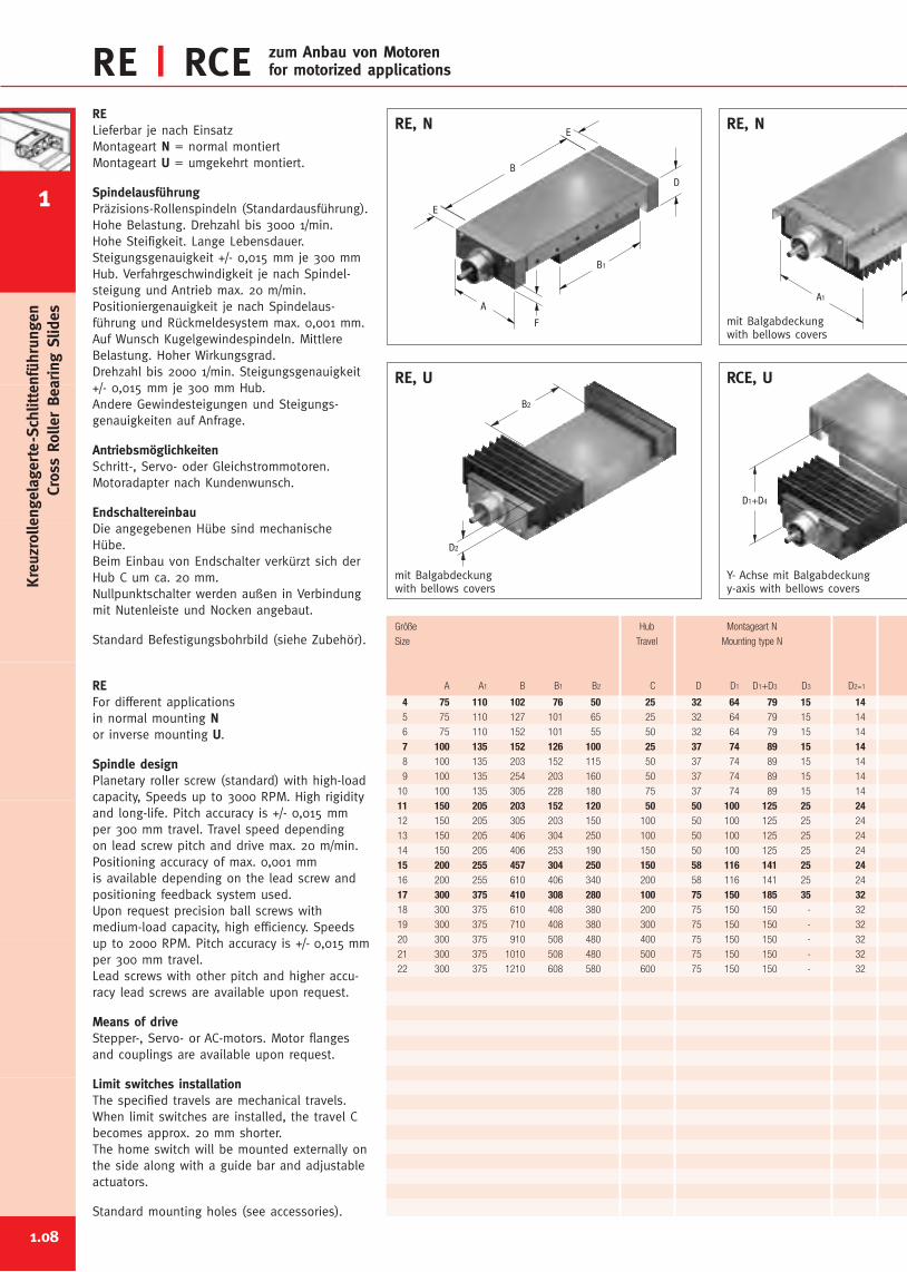
RE | RCE zum Anbau von Motorenfor motorized applications
4 75 110 102 76 50 25 32 64 79 15 145 75 110 127 101 65 25 32 64 79 15 14
6 75 110 152 101 55 50 32 64 79 15 14
7 100 135 152 126 100 25 37 74 89 15 148 100 135 203 152 115 50 37 74 89 15 14
9 100 135 254 203 160 50 37 74 89 15 14
10 100 135 305 228 180 75 37 74 89 15 14
11 150 205 203 152 120 50 50 100 125 25 2412 150 205 305 203 150 100 50 100 125 25 24
13 150 205 406 304 250 100 50 100 125 25 24
14 150 205 406 253 190 150 50 100 125 25 24
15 200 255 457 304 250 150 58 116 141 25 2416 200 255 610 406 340 200 58 116 141 25 24
17 300 375 410 308 280 100 75 150 185 35 3218 300 375 610 408 380 200 75 150 150 - 32
19 300 375 710 408 380 300 75 150 150 - 32
20 300 375 910 508 480 400 75 150 150 - 32
21 300 375 1010 508 480 500 75 150 150 - 32
22 300 375 1210 608 580 600 75 150 150 - 32
RELieferbar je nach EinsatzMontageart N = normal montiertMontageart U = umgekehrt montiert.
SpindelausführungPräzisions-Rollenspindeln (Standardausführung).Hohe Belastung. Drehzahl bis 3000 1/min.Hohe Steifigkeit. Lange Lebensdauer.Steigungsgenauigkeit +/- 0,015 mm je 300 mmHub. Verfahrgeschwindigkeit je nach Spindel-steigung und Antrieb max. 20 m/min.Positioniergenauigkeit je nach Spindelaus-führung und Rückmeldesystem max. 0,001 mm.Auf Wunsch Kugelgewindespindeln. MittlereBelastung. Hoher Wirkungsgrad.Drehzahl bis 2000 1/min. Steigungsgenauigkeit+/- 0,015 mm je 300 mm Hub.Andere Gewindesteigungen und Steigungs-genauigkeiten auf Anfrage.
AntriebsmöglichkeitenSchritt-, Servo- oder Gleichstrommotoren.Motoradapter nach Kundenwunsch.
EndschaltereinbauDie angegebenen Hübe sind mechanischeHübe.Beim Einbau von Endschalter verkürzt sich derHub C um ca. 20 mm.Nullpunktschalter werden außen in Verbindungmit Nutenleiste und Nocken angebaut.
Standard Befestigungsbohrbild (siehe Zubehör).
REFor different applicationsin normal mounting Nor inverse mounting U.
Spindle designPlanetary roller screw (standard) with high-loadcapacity, Speeds up to 3000 RPM. High rigidityand long-life. Pitch accuracy is +/- 0,015 mmper 300 mm travel. Travel speed dependingon lead screw pitch and drive max. 20 m/min.Positioning accuracy of max. 0,001 mmis available depending on the lead screw andpositioning feedback system used.Upon request precision ball screws withmedium-load capacity, high efficiency. Speedsup to 2000 RPM. Pitch accuracy is +/- 0,015 mmper 300 mm travel.Lead screws with other pitch and higher accu-racy lead screws are available upon request.
Means of driveStepper-, Servo- or AC-motors. Motor flangesand couplings are available upon request.
Limit switches installationThe specified travels are mechanical travels.When limit switches are installed, the travel Cbecomes approx. 20 mm shorter.The home switch will be mounted externally onthe side along with a guide bar and adjustableactuators.
Standard mounting holes (see accessories).
mit Balgabdeckungwith bellows covers
Y- Achse mit Balgabdeckungy-axis with bellows covers
RCE, URE, U
Größe Hub Montageart N
Size Travel Mounting type N
A A1 B B1 B2 C D D1 D1+D3 D3 D2=1
RE, NRE, N
mit Balgabdeckungwith bellows covers
1.08
1
Kreuzrollengelagerte-Schlittenführungen
CrossRollerBearing
Slides
B2
D1
D3D1+D3
D4 D5
D1+D5
D6
D1+D6
79 15 94 30 79 15 15 15 11,5 8 x 1 / 8 x 2 8 x 1 / 8 x 2 1,8 590 32,0 18,0 19,079 15 94 30 79 15 15 15 11,5 8 x 1 / 8 x 2 8 x 1 / 8 x 2 2,0 840 45,0 37,0 40,0
79 15 94 30 79 15 15 15 11,5 8 x 1 / 8 x 2 8 x 1 / 8 x 2 2,5 740 40,0 27,0 29,0
89 15 104 30 89 15 15 15 13,5 8 x 1 / 8 x 2 8 x 1 / 8 x 2 4,0 1080 67,0 41,0 48,089 15 104 30 89 15 15 15 13,5 8 x 1 / 8 x 2 8 x 1 / 8 x 2 4,7 1230 76,0 52,0 62,0
84 10 94 20 89 15 15 15 13,5 8 x 1 / 8 x 2 8 x 1 / 8 x 2 6,1 1720 106,0 104,0 124,0
84 10 94 20 89 15 15 15 13,5 8 x 1 / 8 x 2 8 x 1 / 8 x 2 7,0 1820 112,0 118,0 141,0
125 25 150 50 125 25 16 16 19,0 15 x 2 / 15 x 4 20 x 4 10,0 2600 220,0 104,0 123,0100 - 150 50 125 25 16 16 19,0 15 x 2 / 15 x 4 20 x 4 13,2 3200 270,0 157,0 186,0
100 - 125 25 125 25 16 16 19,0 15 x 2 / 15 x 4 20 x 4 18,0 5430 460,0 460,0 545,0
100 - 125 25 125 25 16 16 19,0 15 x 2 / 15 x 4 20 x 4 16,5 3820 320,0 220,0 260,0
116 - 131 15 141 25 16 16 21,5 15 x 2 / 15 x 4 20 x 4 30,0 5030 705,0 445,0 455,0116 - 131 15 141 25 16 16 21,5 15 x 2 / 15 x 4 20 x 4 40,0 6640 935,0 795,0 815,0
185 35 220 70 185 35 20 70 26,0 23 x 4 25 x 4 59,0 8380 3190,0 800,0 825,0150 - 185 35 150 - 20 70 26,0 23 x 4 25 x 4 80,0 10370 3950,0 1205,0 1245,0
150 - 185 35 150 - 20 70 26,0 23 x 4 25 x 4 92,0 8380 3190,0 800,0 825,0
150 - 150 - 150 - 20 70 26,0 23 x 4 25 x 4 110,0 10370 3950,0 1205,0 1245,0
150 - 150 - 150 - 20 90 26,0 23 x 4 25 x 4 125,0 8380 3190,0 800,0 825,0
150 - 150 - 150 - 20 100 26,0 23 x 4 - 145,0 10370 3950,0 1205,0 1245,0
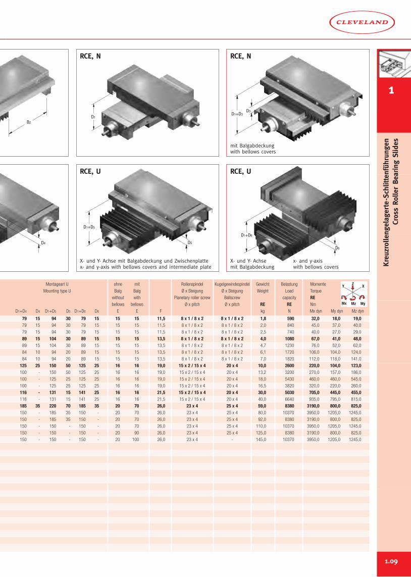
mit Balgabdeckungwith bellows covers
X- und Y- Achse mit Balgabdeckung und Zwischenplattex- and y-axis with bellows covers and intermediate plate
RCE, U RCE, U
Montageart U ohne mit Rollenspindel Kugelgewindespindel Gewicht Belastung Momente
Mounting type U Balg Balg Ø x Steigung Ø x Steigung Weight Load Torque
without with Planetary roller screw Ballscrew capacity REbellows bellows Ø x pitch Ø x pitch RE RE Nm
D1+D4 D4 D1+D5 D5 D1+D6 D6 E E F kg N Mx dyn My dyn Mz dyn
RCE, N RCE, N
Y X
MyMz
Z
Mx
1.09
X- und Y- Achsemit Balgabdeckung
x- and y-axiswith bellows covers
1
Kreuzrollengelagerte-Schlittenführungen
CrossRollerBearing
Slides
D1
B
A
E
A1B1
D
F
B2
D2
Y X
MyMz
Z
Mx
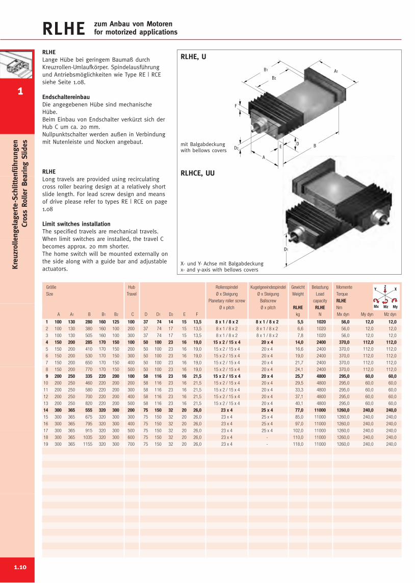
RLHE zum Anbau von Motorenfor motorized applications
1.10
RLHELange Hübe bei geringem Baumaß durchKreuzrollen-Umlaufkörper. Spindelausführungund Antriebsmöglichkeiten wie Type RE | RCEsiehe Seite 1.08.
EndschaltereinbauDie angegebenen Hübe sind mechanischeHübe.Beim Einbau von Endschalter verkürzt sich derHub C um ca. 20 mm.Nullpunktschalter werden außen in Verbindungmit Nutenleiste und Nocken angebaut.
RLHELong travels are provided using recirculatingcross roller bearing design at a relatively shortslide length. For lead screw design and meansof drive please refer to types RE | RCE on page1.08
Limit switches installationThe specified travels are mechanical travels.When limit switches are installed, the travel Cbecomes approx. 20 mm shorter.The home switch will be mounted externally onthe side along with a guide bar and adjustableactuators.
1 100 130 280 160 125 100 37 74 14 15 13,5 8 x 1 / 8 x 2 8 x 1 / 8 x 2 5,5 1020 56,0 12,0 12,02 100 130 380 160 100 200 37 74 17 15 13,5 8 x 1 / 8 x 2 8 x 1 / 8 x 2 6,6 1020 56,0 12,0 12,0
3 100 130 505 160 100 300 37 74 17 15 13,5 8 x 1 / 8 x 2 8 x 1 / 8 x 2 7,8 1020 56,0 12,0 12,0
4 150 200 285 170 150 100 50 100 23 16 19,0 15 x 2 / 15 x 4 20 x 4 14,0 2400 370,0 112,0 112,05 150 200 410 170 150 200 50 100 23 16 19,0 15 x 2 / 15 x 4 20 x 4 16,6 2400 370,0 112,0 112,0
6 150 200 530 170 150 300 50 100 23 16 19,0 15 x 2 / 15 x 4 20 x 4 19,0 2400 370,0 112,0 112,0
7 150 200 650 170 150 400 50 100 23 16 19,0 15 x 2 / 15 x 4 20 x 4 21,7 2400 370,0 112,0 112,0
8 150 200 770 170 150 500 50 100 23 16 19,0 15 x 2 / 15 x 4 20 x 4 24,1 2400 370,0 112,0 112,0
9 200 250 335 220 200 100 58 116 23 16 21,5 15 x 2 / 15 x 4 20 x 4 25,7 4800 295,0 60,0 60,010 200 250 460 220 200 200 58 116 23 16 21,5 15 x 2 / 15 x 4 20 x 4 29,5 4800 295,0 60,0 60,0
11 200 250 580 220 200 300 58 116 23 16 21,5 15 x 2 / 15 x 4 20 x 4 33,3 4800 295,0 60,0 60,0
12 200 250 700 220 200 400 58 116 23 16 21,5 15 x 2 / 15 x 4 20 x 4 37,1 4800 295,0 60,0 60,0
13 200 250 820 220 200 500 58 116 23 16 21,5 15 x 2 / 15 x 4 20 x 4 40,1 4800 295,0 60,0 60,0
14 300 365 555 320 300 200 75 150 32 20 26,0 23 x 4 25 x 4 77,0 11000 1260,0 240,0 240,015 300 365 675 320 300 300 75 150 32 20 26,0 23 x 4 25 x 4 85,0 11000 1260,0 240,0 240,0
16 300 365 795 320 300 400 75 150 32 20 26,0 23 x 4 25 x 4 97,0 11000 1260,0 240,0 240,0
17 300 365 915 320 300 500 75 150 32 20 26,0 23 x 4 25 x 4 102,0 11000 1260,0 240,0 240,0
18 300 365 1035 320 300 600 75 150 32 20 26,0 23 x 4 - 110,0 11000 1260,0 240,0 240,0
19 300 365 1155 320 300 700 75 150 32 20 26,0 23 x 4 - 118,0 11000 1260,0 240,0 240,0
Größe Hub Rollenspindel Kugelgewindespindel Gewicht Belastung Momente
Size Travel Ø x Steigung Ø x Steigung Weight Load Torque
Planetary roller screw Ballscrew capacity RLHEØ x pitch Ø x pitch RLHE RLHE Nm
A A1 B B1 B2 C D D1 D2 E F kg N Mx dyn My dyn Mz dyn
mit Balgabdeckungwith bellows covers
X- und Y- Achse mit Balgabdeckungx- and y-axis with bellows covers
RLHE, U
RLHCE, UU
1
Kreuzrollengelagerte-Schlittenführungen
CrossRollerBearing
Slides
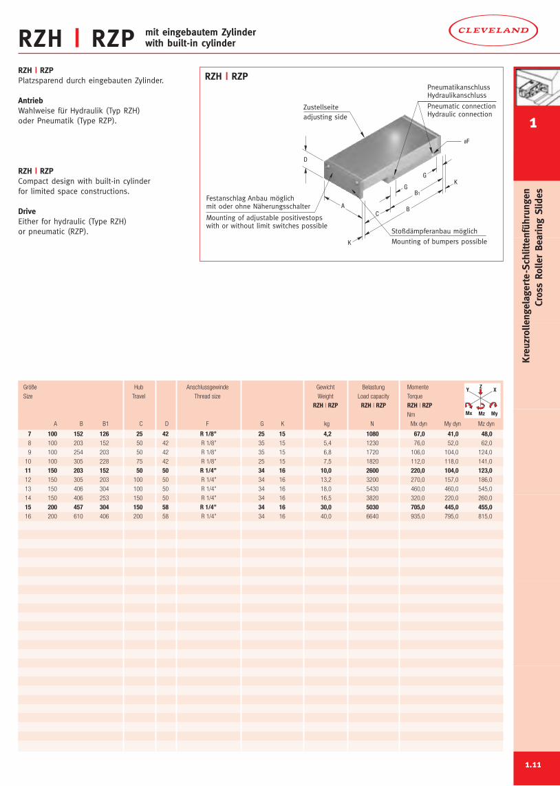
RZH | RZPRZH | RZPPlatzsparend durch eingebauten Zylinder.
AntriebWahlweise für Hydraulik (Typ RZH)oder Pneumatik (Type RZP).
RZH | RZPCompact design with built-in cylinderfor limited space constructions.
DriveEither for hydraulic (Type RZH)or pneumatic (RZP).
Mounting of bumpers possible
Mounting of adjustable positivestopswith or without limit switches possible
adjusting side
Pneumatic connectionHydraulic connection
PneumatikanschlussHydraulikanschluss
Stoßdämpferanbau möglich
Festanschlag Anbau möglichmit oder ohne Näherungsschalter
Zustellseite
ØF
B
K
K
B1
G
G
CA
D
RZH | RZP
7 100 152 126 25 42 R 1/8’’ 25 15 4,2 1080 67,0 41,0 48,08 100 203 152 50 42 R 1/8’’ 35 15 5,4 1230 76,0 52,0 62,0
9 100 254 203 50 42 R 1/8’’ 35 15 6,8 1720 106,0 104,0 124,0
10 100 305 228 75 42 R 1/8’’ 25 15 7,5 1820 112,0 118,0 141,0
11 150 203 152 50 50 R 1/4’’ 34 16 10,0 2600 220,0 104,0 123,012 150 305 203 100 50 R 1/4’’ 34 16 13,2 3200 270,0 157,0 186,0
13 150 406 304 100 50 R 1/4’’ 34 16 18,0 5430 460,0 460,0 545,0
14 150 406 253 150 50 R 1/4’’ 34 16 16,5 3820 320,0 220,0 260,0
15 200 457 304 150 58 R 1/4’’ 34 16 30,0 5030 705,0 445,0 455,016 200 610 406 200 58 R 1/4’’ 34 16 40,0 6640 935,0 795,0 815,0
Größe Hub Anschlussgewinde Gewicht Belastung Momente
Size Travel Thread size Weight Load capacity Torque
RZH | RZP RZH | RZP RZH | RZPNm
A B B1 C D F G K kg N Mx dyn My dyn Mz dyn
Y X
MyMz
Z
Mx
mit eingebautem Zylinderwith built-in cylinder
1.11
1
Kreuzrollengelagerte-Schlittenführungen
CrossRollerBearing
Slides
RQ
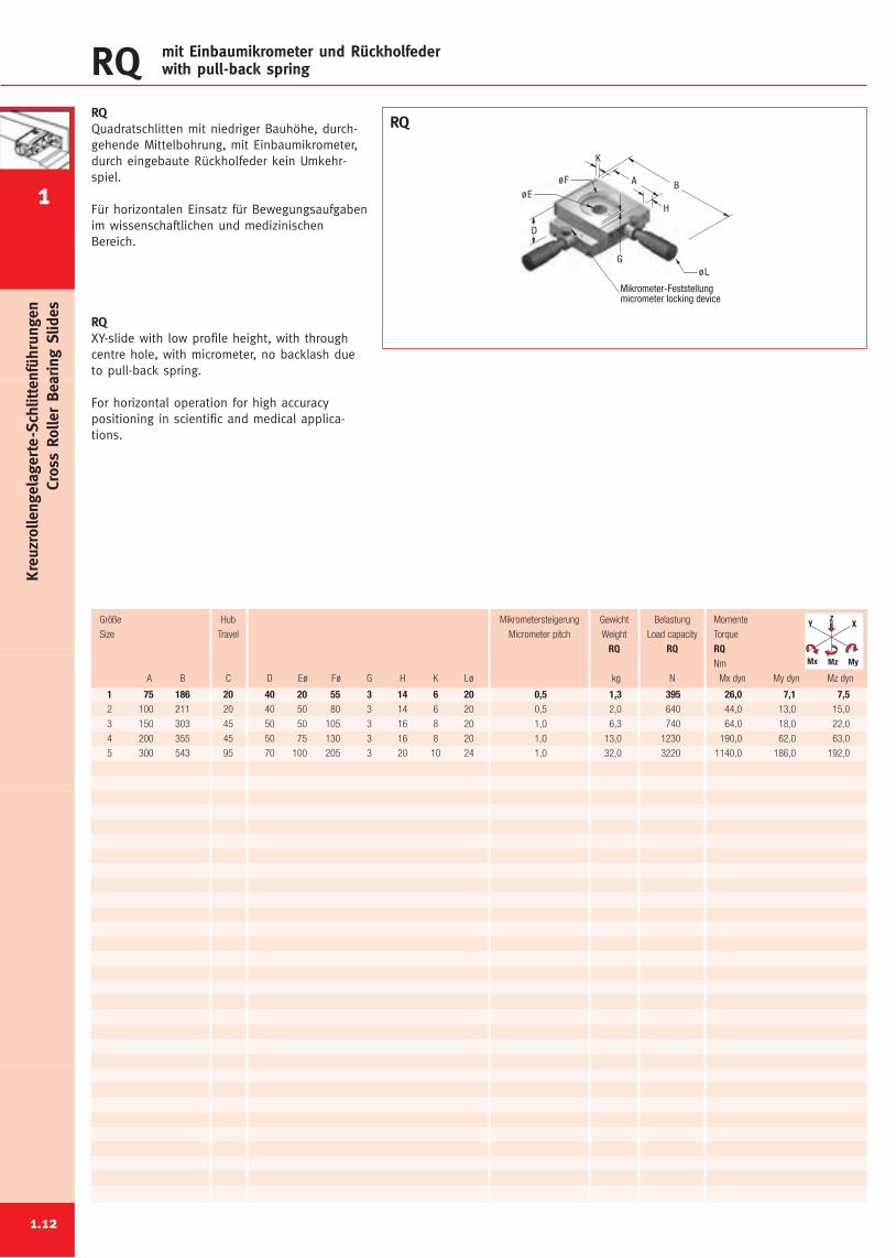
1 75 186 20 40 20 55 3 14 6 20 0,5 1,3 395 26,0 7,1 7,52 100 211 20 40 50 80 3 14 6 20 0,5 2,0 640 44,0 13,0 15,0
3 150 303 45 50 50 105 3 16 8 20 1,0 6,3 740 64,0 18,0 22,0
4 200 355 45 50 75 130 3 16 8 20 1,0 13,0 1230 190,0 62,0 63,0
5 300 543 95 70 100 205 3 20 10 24 1,0 32,0 3220 1140,0 186,0 192,0
Größe Hub Mikrometersteigerung Gewicht Belastung Momente
Size Travel Micrometer pitch Weight Load capacity Torque
RQ RQ RQNm
A B C D Eø Fø G H K Lø kg N Mx dyn My dyn Mz dyn
Y X
MyMz
Z
Mx
mit Einbaumikrometer und Rückholfederwith pull-back spring
1
1.12
Kreuzrollengelagerte-Schlittenführungen
CrossRollerBearing
Slides
RQQuadratschlitten mit niedriger Bauhöhe, durch-gehende Mittelbohrung, mit Einbaumikrometer,durch eingebaute Rückholfeder kein Umkehr-spiel.
Für horizontalen Einsatz für Bewegungsaufgabenim wissenschaftlichen und medizinischenBereich.
RQXY-slide with low profile height, with throughcentre hole, with micrometer, no backlash dueto pull-back spring.
For horizontal operation for high accuracypositioning in scientific and medical applica-tions.
Mikrometer-Feststellungmicrometer locking device
G
D
øEøF
øL
B
H
K
A
RQ
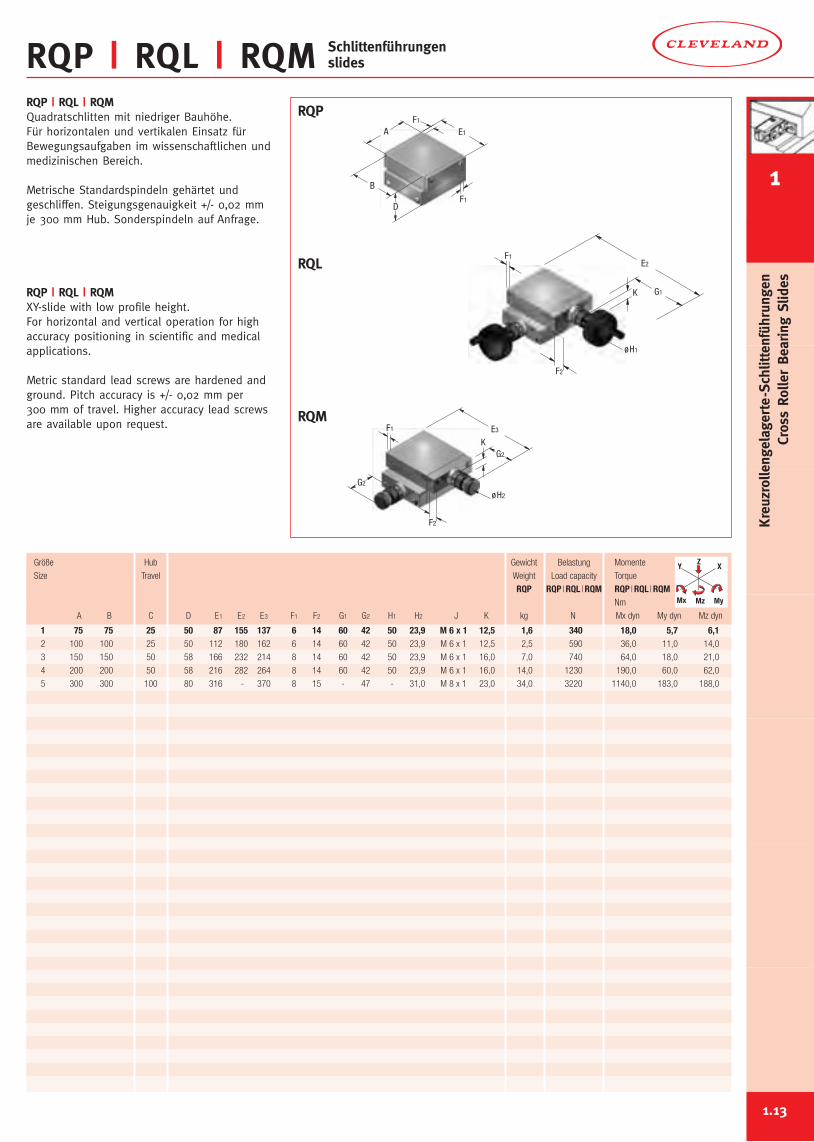
RQP | RQL | RQM Schlittenführungenslides
1.13
1 75 75 25 50 87 155 137 6 14 60 42 50 23,9 M 6 x 1 12,5 1,6 340 18,0 5,7 6,12 100 100 25 50 112 180 162 6 14 60 42 50 23,9 M 6 x 1 12,5 2,5 590 36,0 11,0 14,0
3 150 150 50 58 166 232 214 8 14 60 42 50 23,9 M 6 x 1 16,0 7,0 740 64,0 18,0 21,0
4 200 200 50 58 216 282 264 8 14 60 42 50 23,9 M 6 x 1 16,0 14,0 1230 190,0 60,0 62,0
5 300 300 100 80 316 - 370 8 15 - 47 - 31,0 M 8 x 1 23,0 34,0 3220 1140,0 183,0 188,0
Y X
MyMz
Z
Mx
RQP | RQL | RQMQuadratschlitten mit niedriger Bauhöhe.Für horizontalen und vertikalen Einsatz fürBewegungsaufgaben im wissenschaftlichen undmedizinischen Bereich.
Metrische Standardspindeln gehärtet undgeschliffen. Steigungsgenauigkeit +/- 0,02 mmje 300 mm Hub. Sonderspindeln auf Anfrage.
RQP | RQL | RQMXY-slide with low profile height.For horizontal and vertical operation for highaccuracy positioning in scientific and medicalapplications.
Metric standard lead screws are hardened andground. Pitch accuracy is +/- 0,02 mm per300 mm of travel. Higher accuracy lead screwsare available upon request.
RQP
RQL
RQM
øH1
K G1
F2
F1E2
øH2
K
G2
G2
F2
F1 E3
DF1
E1
B
F1
A
Größe Hub Gewicht Belastung Momente
Size Travel Weight Load capacity Torque
RQP RQP |RQL |RQM RQP |RQL |RQMNm
A B C D E1 E2 E3 F1 F2 G1 G2 H1 H2 J K kg N Mx dyn My dyn Mz dyn
1
Kreuzrollengelagerte-Schlittenführungen
CrossRollerBearing
Slides
Kreuzrollengelagerte SchlittenführungenCross Roller Bearing Slides
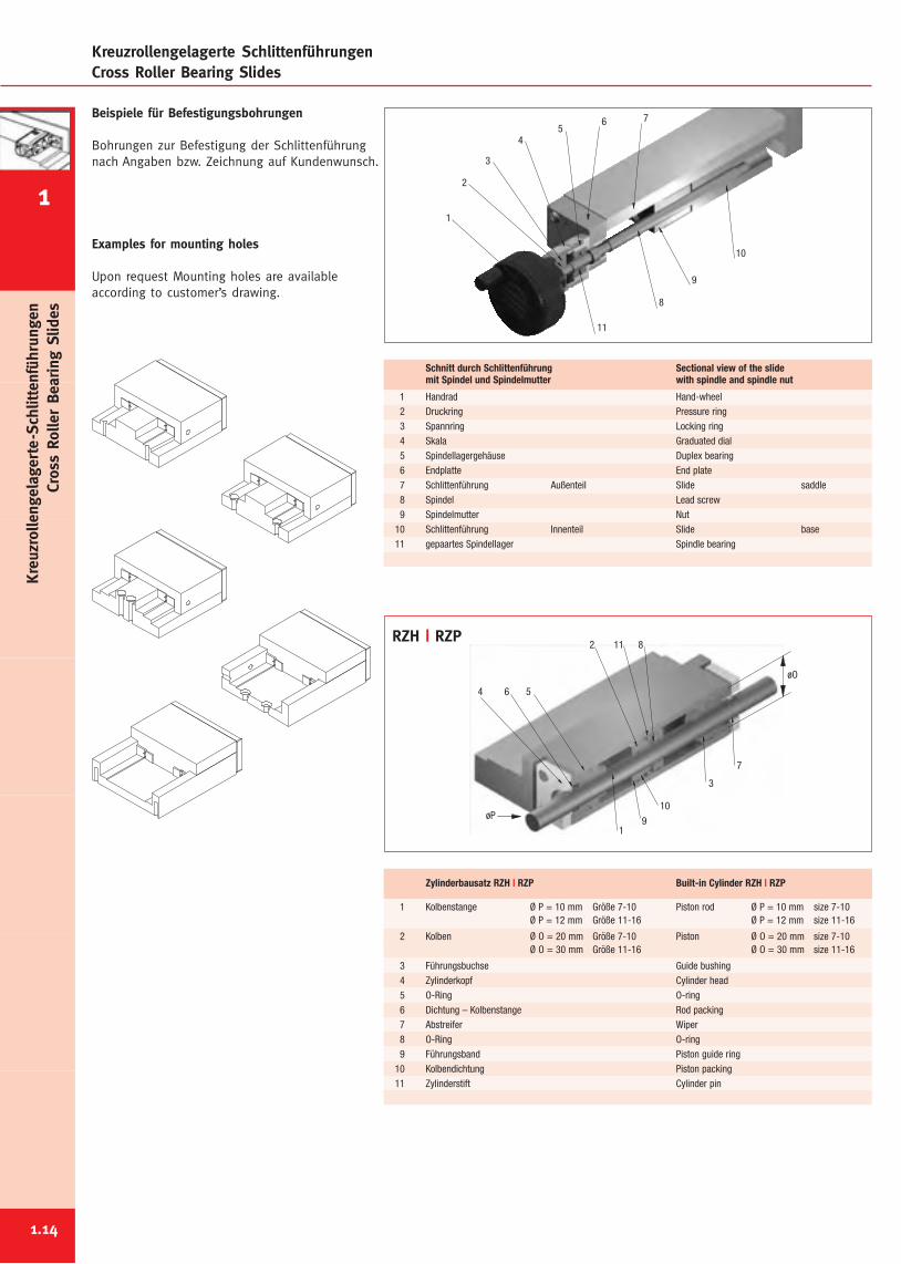
Beispiele für Befestigungsbohrungen
Bohrungen zur Befestigung der Schlittenführungnach Angaben bzw. Zeichnung auf Kundenwunsch.
Examples for mounting holes
Upon request Mounting holes are availableaccording to customer’s drawing.
10
9
8
765
4
3
2
11
1
7
3
811
10
9
2
1
564
øO
øP
RZH | RZP
1 Handrad Hand-wheel2 Druckring Pressure ring3 Spannring Locking ring4 Skala Graduated dial5 Spindellagergehäuse Duplex bearing6 Endplatte End plate7 Schlittenführung Außenteil Slide saddle8 Spindel Lead screw9 Spindelmutter Nut
10 Schlittenführung Innenteil Slide base11 gepaartes Spindellager Spindle bearing
Schnitt durch Schlittenführung Sectional view of the slidemit Spindel und Spindelmutter with spindle and spindle nut
1 Kolbenstange Ø P = 10 mm Größe 7-10 Piston rod Ø P = 10 mm size 7-10Ø P = 12 mm Größe 11-16 Ø P = 12 mm size 11-16
2 Kolben Ø O = 20 mm Größe 7-10 Piston Ø O = 20 mm size 7-10Ø O = 30 mm Größe 11-16 Ø O = 30 mm size 11-16
3 Führungsbuchse Guide bushing4 Zylinderkopf Cylinder head5 O-Ring O-ring6 Dichtung – Kolbenstange Rod packing7 Abstreifer Wiper8 O-Ring O-ring9 Führungsband Piston guide ring
10 Kolbendichtung Piston packing11 Zylinderstift Cylinder pin
Zylinderbausatz RZH | RZP Built-in Cylinder RZH | RZP
1.14
1
Kreuzrollengelagerte-Schlittenführungen
CrossRollerBearing
Slides
Nadelrollengelagerte SchlittenführungenNeedle Roller Bearing Slides
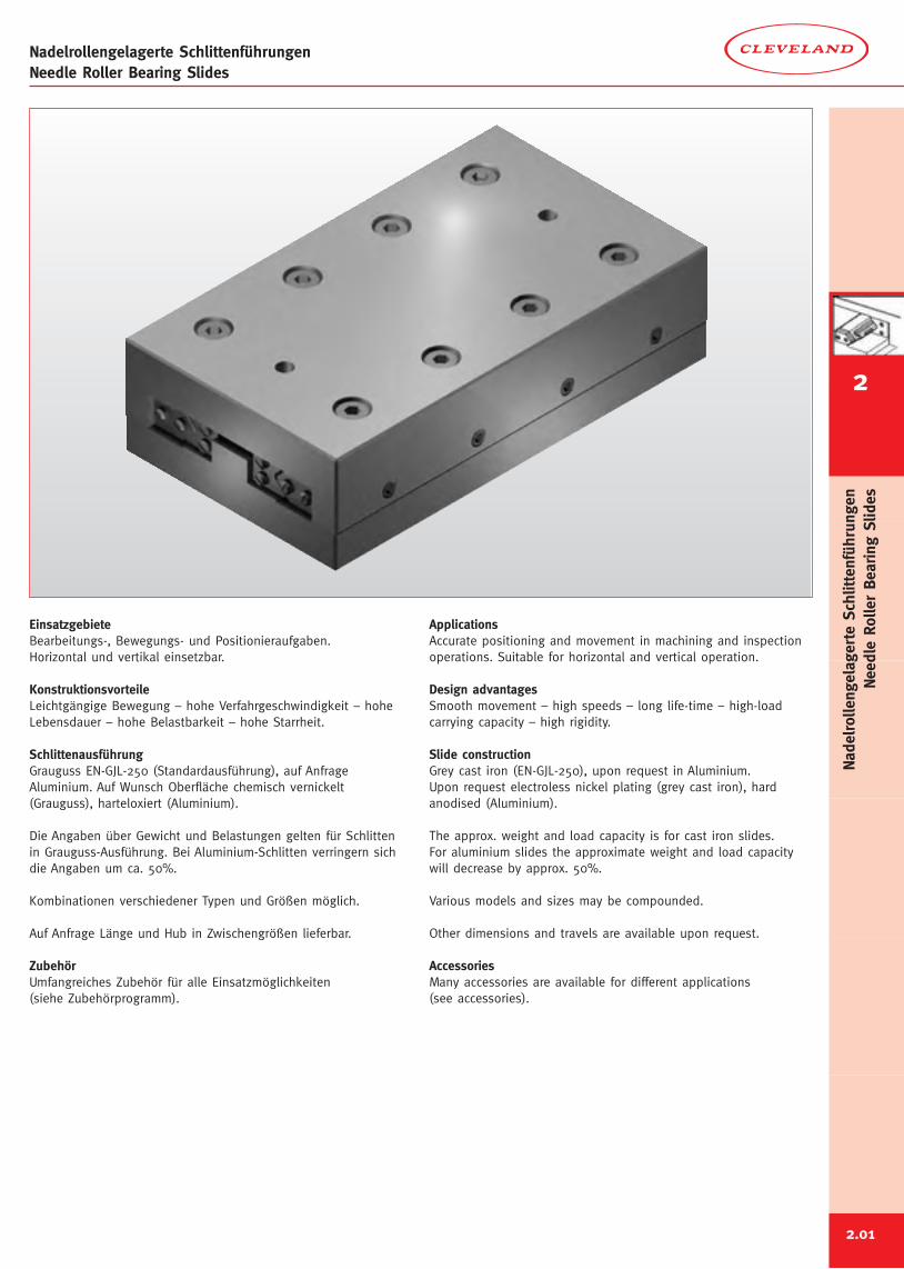
EinsatzgebieteBearbeitungs-, Bewegungs- und Positionieraufgaben.Horizontal und vertikal einsetzbar.
KonstruktionsvorteileLeichtgängige Bewegung – hohe Verfahrgeschwindigkeit – hoheLebensdauer – hohe Belastbarkeit – hohe Starrheit.
SchlittenausführungGrauguss EN-GJL-250 (Standardausführung), auf AnfrageAluminium. Auf Wunsch Oberfläche chemisch vernickelt(Grauguss), harteloxiert (Aluminium).
Die Angaben über Gewicht und Belastungen gelten für Schlittenin Grauguss-Ausführung. Bei Aluminium-Schlitten verringern sichdie Angaben um ca. 50%.
Kombinationen verschiedener Typen und Größen möglich.
Auf Anfrage Länge und Hub in Zwischengrößen lieferbar.
ZubehörUmfangreiches Zubehör für alle Einsatzmöglichkeiten(siehe Zubehörprogramm).
ApplicationsAccurate positioning and movement in machining and inspectionoperations. Suitable for horizontal and vertical operation.
Design advantagesSmooth movement – high speeds – long life-time – high-loadcarrying capacity – high rigidity.
Slide constructionGrey cast iron (EN-GJL-250), upon request in Aluminium.Upon request electroless nickel plating (grey cast iron), hardanodised (Aluminium).
The approx. weight and load capacity is for cast iron slides.For aluminium slides the approximate weight and load capacitywill decrease by approx. 50%.
Various models and sizes may be compounded.
Other dimensions and travels are available upon request.
AccessoriesMany accessories are available for different applications(see accessories).
2
2.01
NadelrollengelagerteSchlittenführungen
NeedleRollerBearing
Slides
Nadelrollengelagerte SchlittenführungenNeedle Roller Bearing Slides
NO NP NL NM
NENE,U
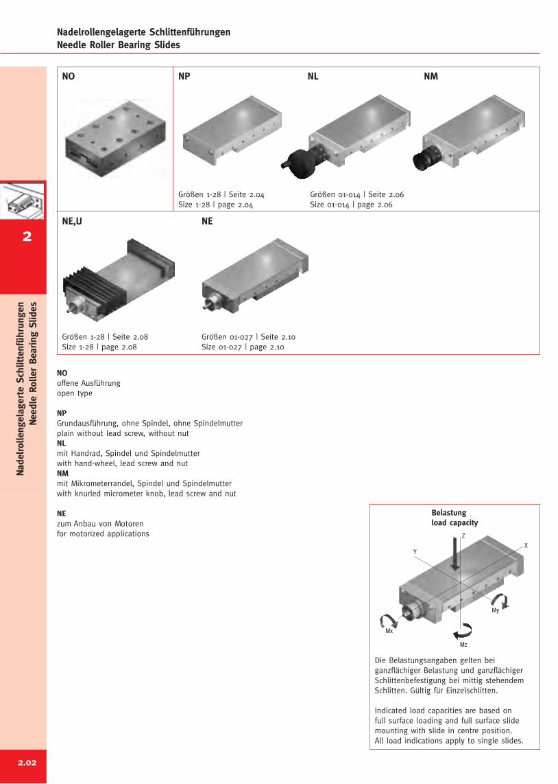
NOoffene Ausführungopen type
NPGrundausführung, ohne Spindel, ohne Spindelmutterplain without lead screw, without nutNLmit Handrad, Spindel und Spindelmutterwith hand-wheel, lead screw and nutNMmit Mikrometerrandel, Spindel und Spindelmutterwith knurled micrometer knob, lead screw and nut
NEzum Anbau von Motorenfor motorized applications
2.02
Größen 1-28 | Seite 2.04Size 1-28 | page 2.04
Größen 01-014 | Seite 2.06Size 01-014 | page 2.06
Größen 1-28 | Seite 2.08Size 1-28 | page 2.08
Größen 01-027 | Seite 2.10Size 01-027 | page 2.10
Z
Mx
Mz
My
YX
Belastungload capacity
Die Belastungsangaben gelten beiganzflächiger Belastung und ganzflächigerSchlittenbefestigung bei mittig stehendemSchlitten. Gültig für Einzelschlitten.
Indicated load capacities are based onfull surface loading and full surface slidemounting with slide in centre position.All load indications apply to single slides.
NadelrollengelagerteSchlittenführungen
NeedleRollerBearing
Slides
2
k
G
E
øF
g
h
A
B
D
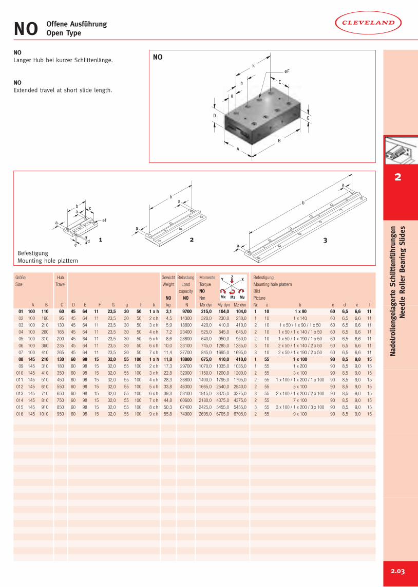
NOLanger Hub bei kurzer Schlittenlänge.
NOExtended travel at short slide length.
NO Offene AusführungOpen Type
NO
01 100 110 60 45 64 11 23,5 30 50 1 x h 3,1 9700 215,0 104,0 104,0 1 10 1 x 90 60 6,5 6,6 1102 100 160 95 45 64 11 23,5 30 50 2 x h 4,5 14300 320,0 230,0 230,0 1 10 1 x 140 60 6,5 6,6 11
03 100 210 130 45 64 11 23,5 30 50 3 x h 5,9 18800 420,0 410,0 410,0 2 10 1 x 50 / 1 x 90 / 1 x 50 60 6,5 6,6 11
04 100 260 165 45 64 11 23,5 30 50 4 x h 7,2 23400 525,0 645,0 645,0 2 10 1 x 50 / 1 x 140 / 1 x 50 60 6,5 6,6 11
05 100 310 200 45 64 11 23,5 30 50 5 x h 8,6 28600 640,0 950,0 950,0 2 10 1 x 50 / 1 x 190 / 1 x 50 60 6,5 6,6 11
06 100 360 235 45 64 11 23,5 30 50 6 x h 10,0 33100 745,0 1285,0 1285,0 3 10 2 x 50 / 1 x 140 / 2 x 50 60 6,5 6,6 11
07 100 410 265 45 64 11 23,5 30 50 7 x h 11,4 37700 845,0 1695,0 1695,0 3 10 2 x 50 / 1 x 190 / 2 x 50 60 6,5 6,6 11
08 145 210 130 60 98 15 32,0 55 100 1 x h 11,8 18800 675,0 410,0 410,0 1 55 1 x 100 90 8,5 9,0 1509 145 310 180 60 98 15 32,0 55 100 2 x h 17,3 29700 1070,0 1035,0 1035,0 1 55 1 x 200 90 8,5 9,0 15
010 145 410 350 60 98 15 32,0 55 100 3 x h 22,8 32000 1150,0 1200,0 1200,0 2 55 3 x 100 90 8,5 9,0 15
011 145 510 450 60 98 15 32,0 55 100 4 x h 28,3 38800 1400,0 1795,0 1795,0 2 55 1 x 100 / 1 x 200 / 1 x 100 90 8,5 9,0 15
012 145 610 550 60 98 15 32,0 55 100 5 x h 33,8 46300 1665,0 2540,0 2540,0 2 55 5 x 100 90 8,5 9,0 15
013 145 710 650 60 98 15 32,0 55 100 6 x h 39,3 53100 1915,0 3375,0 3375,0 3 55 2 x 100 / 1 x 200 / 2 x 100 90 8,5 9,0 15
014 145 810 750 60 98 15 32,0 55 100 7 x h 44,8 60600 2180,0 4375,0 4375,0 2 55 7 x 100 90 8,5 9,0 15
015 145 910 850 60 98 15 32,0 55 100 8 x h 50,3 67400 2425,0 5455,0 5455,0 3 55 3 x 100 / 1 x 200 / 3 x 100 90 8,5 9,0 15
016 145 1010 950 60 98 15 32,0 55 100 9 x h 55,8 74900 2695,0 6705,0 6705,0 2 55 9 x 100 90 8,5 9,0 15
Größe Hub Gewicht Belastung Momente Befestigung
Size Travel Weight Load Torque Mounting hole plattern
capacity NO Bild
NO NO Nm Picture
A B C D E F G g h k kg N Mx dyn My dyn Mz dyn Nr. a b c d e f
Y X
MyMz
Z
Mx
2.03
ba
a
a
a
b
e
øf
ab
a
d
c
BefestigungMounting hole plattern
21 3
2
NadelrollengelagerteSchlittenführungen
NeedleRollerBearing
Slides
E2
F2
K
G1
øH1
E1
F1
B
F1
B1
CA
D1
NP | NL | NMSchlittenführungen (Größen 1 - 28)Slides (size 1 - 28)
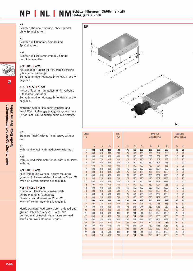
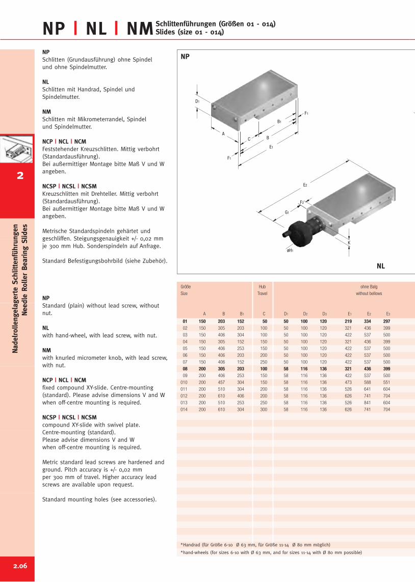
NPSchlitten (Grundausführung) ohne Spindel,ohne Spindelmutter.
NLSchlitten mit Handrad, Spindel undSpindelmutter.
NMSchlitten mit Mikrometerrandel, Spindelund Spindelmutter.
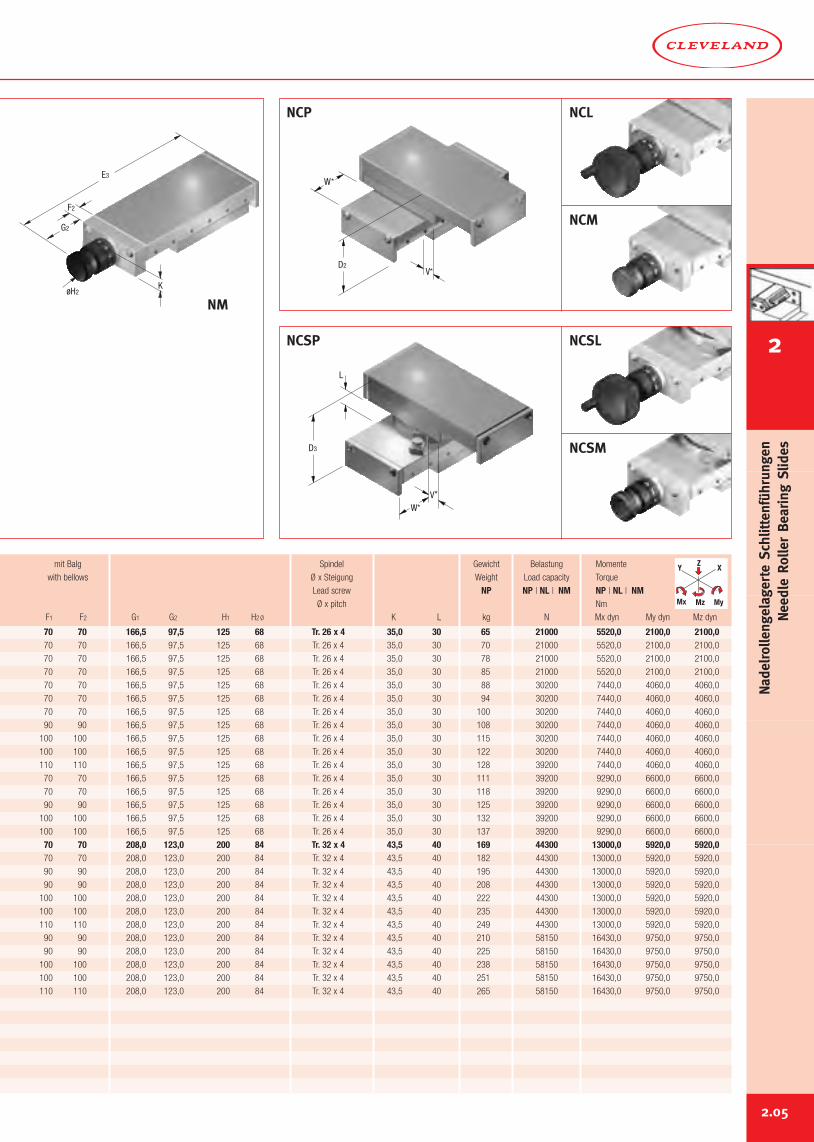
NCP | NCL | NCMFeststehender Kreuzschlitten. Mittig verbohrt(Standardausführung).Bei außermittiger Montage bitte Maß V und Wangeben.
NCSP | NCSL | NCSMKreuzschlitten mit Drehteller. Mittig verbohrt(Standardausführung).Bei außermittiger Montage bitte Maß V und Wangeben.
Metrische Standardspindeln gehärtet undgeschliffen. Steigungsgenauigkeit +/- 0,02 mmje 300 mm Hub. Sonderspindeln auf Anfrage.
NPStandard (plain) without lead screw, withoutnut.
NLwith hand-wheel, with lead screw, with nut.
NMwith knurled micrometer knob, with lead screw,with nut.
NCP | NCL | NCMfixed compound XY-slide. Centre-mounting(standard). Please advise dimensions V and Wwhen off-centre mounting is required.
NCSP | NCSL | NCSMcompound XY-slide with swivel plate.Centre-mounting (standard).Please advise dimensions V and Wwhen off-centre mounting is required.
Metric standard lead screws are hardened andground. Pitch accuracy is +/- 0,02 mmper 300 mm of travel. Higher accuracy leadscrews are available upon request.
NP
NL
1 300 410 308 100 75 150 190 430 607 538 10 202 300 510 308 200 75 150 190 530 707 638 10 20
3 300 610 308 300 75 150 190 630 807 738 10 20
4 300 710 308 400 75 150 190 730 907 838 10 20
5 300 610 408 200 75 150 190 630 807 738 10 20
6 300 710 408 300 75 150 190 730 907 838 10 20
7 300 810 408 400 75 150 190 830 1007 938 10 20
8 300 910 408 500 75 150 190 930 1107 1038 10 20
9 300 1010 408 600 75 150 190 1030 1207 1138 10 20
10 300 1110 408 700 75 150 190 1130 1307 1238 10 20
11 300 1210 408 800 75 150 190 1230 1407 1338 10 20
12 300 810 508 300 75 150 190 830 1007 938 10 20
13 300 910 508 400 75 150 190 930 1107 1038 10 20
14 300 1010 508 500 75 150 190 1030 1207 1138 10 20
15 300 1110 508 600 75 150 190 1130 1307 1238 10 20
16 300 1210 508 700 75 150 190 1230 1407 1338 10 20
17 400 610 408 200 102 204 244 650 868 783 20 3018 400 710 408 300 102 204 244 750 968 883 20 30
19 400 810 408 400 102 204 244 850 1068 983 20 30
20 400 910 408 500 102 204 244 950 1168 1083 20 30
21 400 1010 408 600 102 204 244 1050 1268 1183 20 30
22 400 1110 408 700 102 204 244 1150 1368 1283 20 30
23 400 1210 408 800 102 204 244 1250 1468 1383 20 30
24 400 810 508 300 102 204 244 850 1068 983 20 30
25 400 910 508 400 102 204 244 950 1168 1083 20 30
26 400 1010 508 500 102 204 244 1050 1268 1183 20 30
27 400 1110 508 600 102 204 244 1150 1368 1283 20 30
28 400 1210 508 700 102 204 244 1250 1468 1383 20 30
Größe Hub ohne Balg ohne Balg
Size Travel without bellows without bellows
A B B1 C D1 D2 D3 E1 E2 E3 F1 F2
2.04
NadelrollengelagerteSchlittenführungen
NeedleRollerBearing
Slides
2
W*
L
V*
D3
D2
W*
V*
NCP NCL
NCM
NCSL
NCSM
NCSP
70 70 166,5 97,5 125 68 Tr. 26 x 4 35,0 30 65 21000 5520,0 2100,0 2100,070 70 166,5 97,5 125 68 Tr. 26 x 4 35,0 30 70 21000 5520,0 2100,0 2100,0
70 70 166,5 97,5 125 68 Tr. 26 x 4 35,0 30 78 21000 5520,0 2100,0 2100,0
70 70 166,5 97,5 125 68 Tr. 26 x 4 35,0 30 85 21000 5520,0 2100,0 2100,0
70 70 166,5 97,5 125 68 Tr. 26 x 4 35,0 30 88 30200 7440,0 4060,0 4060,0
70 70 166,5 97,5 125 68 Tr. 26 x 4 35,0 30 94 30200 7440,0 4060,0 4060,0
70 70 166,5 97,5 125 68 Tr. 26 x 4 35,0 30 100 30200 7440,0 4060,0 4060,0
90 90 166,5 97,5 125 68 Tr. 26 x 4 35,0 30 108 30200 7440,0 4060,0 4060,0
100 100 166,5 97,5 125 68 Tr. 26 x 4 35,0 30 115 30200 7440,0 4060,0 4060,0
100 100 166,5 97,5 125 68 Tr. 26 x 4 35,0 30 122 30200 7440,0 4060,0 4060,0
110 110 166,5 97,5 125 68 Tr. 26 x 4 35,0 30 128 39200 7440,0 4060,0 4060,0
70 70 166,5 97,5 125 68 Tr. 26 x 4 35,0 30 111 39200 9290,0 6600,0 6600,0
70 70 166,5 97,5 125 68 Tr. 26 x 4 35,0 30 118 39200 9290,0 6600,0 6600,0
90 90 166,5 97,5 125 68 Tr. 26 x 4 35,0 30 125 39200 9290,0 6600,0 6600,0
100 100 166,5 97,5 125 68 Tr. 26 x 4 35,0 30 132 39200 9290,0 6600,0 6600,0
100 100 166,5 97,5 125 68 Tr. 26 x 4 35,0 30 137 39200 9290,0 6600,0 6600,0
70 70 208,0 123,0 200 84 Tr. 32 x 4 43,5 40 169 44300 13000,0 5920,0 5920,070 70 208,0 123,0 200 84 Tr. 32 x 4 43,5 40 182 44300 13000,0 5920,0 5920,0
90 90 208,0 123,0 200 84 Tr. 32 x 4 43,5 40 195 44300 13000,0 5920,0 5920,0
90 90 208,0 123,0 200 84 Tr. 32 x 4 43,5 40 208 44300 13000,0 5920,0 5920,0
100 100 208,0 123,0 200 84 Tr. 32 x 4 43,5 40 222 44300 13000,0 5920,0 5920,0
100 100 208,0 123,0 200 84 Tr. 32 x 4 43,5 40 235 44300 13000,0 5920,0 5920,0
110 110 208,0 123,0 200 84 Tr. 32 x 4 43,5 40 249 44300 13000,0 5920,0 5920,0
90 90 208,0 123,0 200 84 Tr. 32 x 4 43,5 40 210 58150 16430,0 9750,0 9750,0
90 90 208,0 123,0 200 84 Tr. 32 x 4 43,5 40 225 58150 16430,0 9750,0 9750,0
100 100 208,0 123,0 200 84 Tr. 32 x 4 43,5 40 238 58150 16430,0 9750,0 9750,0
100 100 208,0 123,0 200 84 Tr. 32 x 4 43,5 40 251 58150 16430,0 9750,0 9750,0
110 110 208,0 123,0 200 84 Tr. 32 x 4 43,5 40 265 58150 16430,0 9750,0 9750,0
mit Balg Spindel Gewicht Belastung Momente
with bellows Ø x Steigung Weight Load capacity Torque
Lead screw NP NP | NL | NM NP | NL | NMØ x pitch Nm
F1 F2 G1 G2 H1 H2Ø K L kg N Mx dyn My dyn Mz dyn
Y X
MyMz
Z
Mx
E3
F2
K
G2
øH2
NM
2.05
2
NadelrollengelagerteSchlittenführungen
NeedleRollerBearing
Slides
NPSchlitten (Grundausführung) ohne Spindelund ohne Spindelmutter.
NLSchlitten mit Handrad, Spindel undSpindelmutter.
NMSchlitten mit Mikrometerrandel, Spindelund Spindelmutter.
NCP | NCL | NCMFeststehender Kreuzschlitten. Mittig verbohrt(Standardausführung).Bei außermittiger Montage bitte Maß V und Wangeben.
NCSP | NCSL | NCSMKreuzschlitten mit Drehteller. Mittig verbohrt(Standardausführung).Bei außermittiger Montage bitte Maß V und Wangeben.
Metrische Standardspindeln gehärtet undgeschliffen. Steigungsgenauigkeit +/- 0,02 mmje 300 mm Hub. Sonderspindeln auf Anfrage.
Standard Befestigungsbohrbild (siehe Zubehör).
NPStandard (plain) without lead screw, withoutnut.
NLwith hand-wheel, with lead screw, with nut.
NMwith knurled micrometer knob, with lead screw,with nut.
NCP | NCL | NCMfixed compound XY-slide. Centre-mounting(standard). Please advise dimensions V and Wwhen off-centre mounting is required.
NCSP | NCSL | NCSMcompound XY-slide with swivel plate.Centre-mounting (standard).Please advise dimensions V and Wwhen off-centre mounting is required.
Metric standard lead screws are hardened andground. Pitch accuracy is +/- 0,02 mmper 300 mm of travel. Higher accuracy leadscrews are available upon request.
Standard mounting holes (see accessories).
2.06
NP | NL | NMSchlittenführungen (Größen 01 - 014)Slides (size 01 - 014)
E2
F2
K
G1
øH1
E1
F1
B
F1
B1
CA
D1
NP
NL
01 150 203 152 50 50 100 120 219 334 29702 150 305 203 100 50 100 120 321 436 399
03 150 406 304 100 50 100 120 422 537 500
04 150 305 152 150 50 100 120 321 436 399
05 150 406 253 150 50 100 120 422 537 500
06 150 406 203 200 50 100 120 422 537 500
07 150 406 152 250 50 100 120 422 537 500
08 200 305 203 100 58 116 136 321 436 39909 200 406 253 150 58 116 136 422 537 500
010 200 457 304 150 58 116 136 473 588 551
011 200 510 304 200 58 116 136 526 641 604
012 200 610 406 200 58 116 136 626 741 704
013 200 510 253 250 58 116 136 526 841 604
014 200 610 304 300 58 116 136 626 741 704
Größe Hub ohne Balg
Size Travel without bellows
A B B1 C D1 D2 D3 E1 E2 E3
*hand-wheels (for sizes 6-10 with Ø 63 mm, and for sizes 11-14 with Ø 80 mm possible)
*Handrad (für Größe 6-10 Ø 63 mm, für Größe 11-14 Ø 80 mm möglich)
NadelrollengelagerteSchlittenführungen
NeedleRollerBearing
Slides
2
2.07
W*
L
V*
D3
D2
W*
V*
NCP NCL
NCM
NCSL
NCSM
NCSP
E3
F2
K
G2
øH2
NM
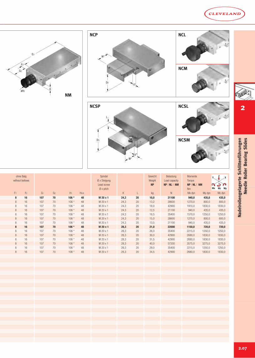
8 16 107 70 106 * 48 M 20 x 1 24,3 20 10,0 21100 940,0 435,0 435,08 16 107 70 106 * 48 M 20 x 1 24,3 20 13,2 28600 1270,0 800,0 800,0
8 16 107 70 106 * 48 M 20 x 1 24,3 20 18,0 42900 1910,0 1830,0 1830,0
8 16 107 70 106 * 48 M 20 x 1 24,3 20 12,5 21100 940,0 435,0 435,0
8 16 107 70 106 * 48 M 20 x 1 24,3 20 16,5 35400 1570,0 1250,0 1250,0
8 16 107 70 106 * 48 M 20 x 1 24,3 20 15,0 28600 1270,0 800,0 800,0
8 16 107 70 106 * 48 M 20 x 1 24,3 20 13,5 21100 940,0 435,0 435,0
8 16 107 70 106 * 48 M 20 x 1 28,3 20 21,0 22000 1150,0 720,0 720,08 16 107 70 106 * 48 M 20 x 1 28,3 20 26,0 35400 2215,0 1250,0 1250,0
8 16 107 70 106 * 48 M 20 x 1 28,3 20 30,0 42900 2680,0 1830,0 1830,0
8 16 107 70 106 * 48 M 20 x 1 28,3 20 31,5 42900 2680,0 1830,0 1830,0
8 16 107 70 106 * 48 M 20 x 1 28,3 20 40,0 57200 3575,0 3275,0 3275,0
8 16 107 70 106 * 48 M 20 x 1 28,3 20 29,0 35400 2215,0 1250,0 1250,0
8 16 107 70 106 * 48 M 20 x 1 28,3 20 34,5 42900 2680,0 1830,0 1830,0
ohne Balg Spindel Gewicht Belastung Momente
without bellows Ø x Steigung Weight Load capacity Torque
Lead screw NP NP | NL | NM NP | NL | NMØ x pitch Nm
F1 F2 G1 G2 H1 H2Ø K L kg N Mx dyn My dyn Mz dyn
Y X
MyMz
Z
Mx
2
NadelrollengelagerteSchlittenführungen
NeedleRollerBearing
Slides
B2
D2
D1+D4
D4
NE | NCE zum Anbau von Motoren (Größen 1 - 28)for motorized applications (size 1 - 28)
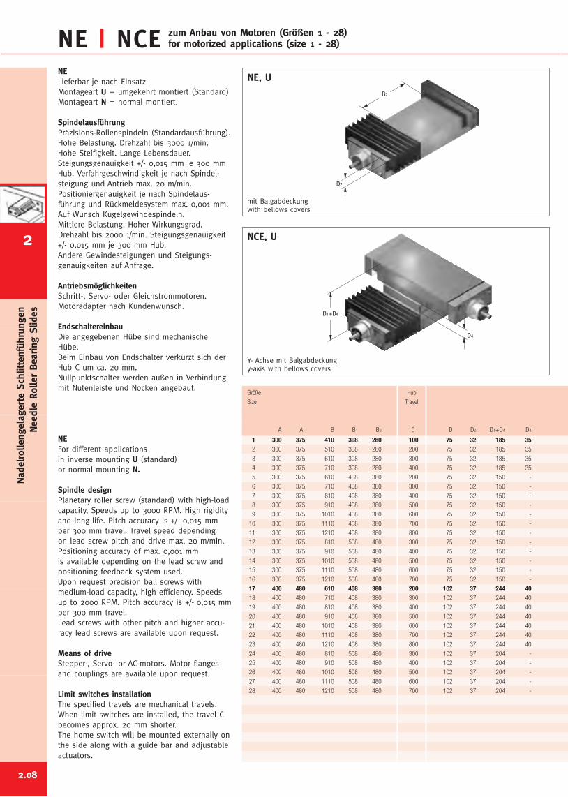
1 300 375 410 308 280 100 75 32 185 352 300 375 510 308 280 200 75 32 185 35
3 300 375 610 308 280 300 75 32 185 35
4 300 375 710 308 280 400 75 32 185 35
5 300 375 610 408 380 200 75 32 150 -
6 300 375 710 408 380 300 75 32 150 -
7 300 375 810 408 380 400 75 32 150 -
8 300 375 910 408 380 500 75 32 150 -
9 300 375 1010 408 380 600 75 32 150 -
10 300 375 1110 408 380 700 75 32 150 -
11 300 375 1210 408 380 800 75 32 150 -
12 300 375 810 508 480 300 75 32 150 -
13 300 375 910 508 480 400 75 32 150 -
14 300 375 1010 508 480 500 75 32 150 -
15 300 375 1110 508 480 600 75 32 150 -
16 300 375 1210 508 480 700 75 32 150 -
17 400 480 610 408 380 200 102 37 244 4018 400 480 710 408 380 300 102 37 244 40
19 400 480 810 408 380 400 102 37 244 40
20 400 480 910 408 380 500 102 37 244 40
21 400 480 1010 408 380 600 102 37 244 40
22 400 480 1110 408 380 700 102 37 244 40
23 400 480 1210 408 380 800 102 37 244 40
24 400 480 810 508 480 300 102 37 204 -
25 400 480 910 508 480 400 102 37 204 -
26 400 480 1010 508 480 500 102 37 204 -
27 400 480 1110 508 480 600 102 37 204 -
28 400 480 1210 508 480 700 102 37 204 -
NELieferbar je nach EinsatzMontageart U = umgekehrt montiert (Standard)Montageart N = normal montiert.
SpindelausführungPräzisions-Rollenspindeln (Standardausführung).Hohe Belastung. Drehzahl bis 3000 1/min.Hohe Steifigkeit. Lange Lebensdauer.Steigungsgenauigkeit +/- 0,015 mm je 300 mmHub. Verfahrgeschwindigkeit je nach Spindel-steigung und Antrieb max. 20 m/min.Positioniergenauigkeit je nach Spindelaus-führung und Rückmeldesystem max. 0,001 mm.Auf Wunsch Kugelgewindespindeln.Mittlere Belastung. Hoher Wirkungsgrad.Drehzahl bis 2000 1/min. Steigungsgenauigkeit+/- 0,015 mm je 300 mm Hub.Andere Gewindesteigungen und Steigungs-genauigkeiten auf Anfrage.
AntriebsmöglichkeitenSchritt-, Servo- oder Gleichstrommotoren.Motoradapter nach Kundenwunsch.
EndschaltereinbauDie angegebenen Hübe sind mechanischeHübe.Beim Einbau von Endschalter verkürzt sich derHub C um ca. 20 mm.Nullpunktschalter werden außen in Verbindungmit Nutenleiste und Nocken angebaut.
NEFor different applicationsin inverse mounting U (standard)or normal mounting N.
Spindle designPlanetary roller screw (standard) with high-loadcapacity, Speeds up to 3000 RPM. High rigidityand long-life. Pitch accuracy is +/- 0,015 mmper 300 mm travel. Travel speed dependingon lead screw pitch and drive max. 20 m/min.Positioning accuracy of max. 0,001 mmis available depending on the lead screw andpositioning feedback system used.Upon request precision ball screws withmedium-load capacity, high efficiency. Speedsup to 2000 RPM. Pitch accuracy is +/- 0,015 mmper 300 mm travel.Lead screws with other pitch and higher accu-racy lead screws are available upon request.
Means of driveStepper-, Servo- or AC-motors. Motor flangesand couplings are available upon request.
Limit switches installationThe specified travels are mechanical travels.When limit switches are installed, the travel Cbecomes approx. 20 mm shorter.The home switch will be mounted externally onthe side along with a guide bar and adjustableactuators.
Y- Achse mit Balgabdeckungy-axis with bellows covers
NCE, U
NE, U
Größe Hub
Size Travel
A A1 B B1 B2 C D D2 D1+D4 D4
mit Balgabdeckungwith bellows covers
2.08
NadelrollengelagerteSchlittenführungen
NeedleRollerBearing
Slides
2
D5
D1+D5
D6
D1+D6
220 70 185 35 20 70 26 23 x 4 70,0 21000 5520,0 2100,0 2100,0220 70 185 35 20 70 26 23 x 4 75,0 21000 5520,0 2100,0 2100,0
220 70 185 35 20 70 26 23 x 4 83,0 21000 5520,0 2100,0 2100,0
220 70 185 35 20 70 26 23 x 4 90,0 21000 5520,0 2100,0 2100,0
185 35 150 - 20 70 26 23 x 4 93,0 30200 7440,0 4060,0 4060,0
185 35 150 - 20 70 26 23 x 4 98,0 30200 7440,0 4060,0 4060,0
185 35 150 - 20 70 26 23 x 4 105,0 30200 7440,0 4060,0 4060,0
185 35 150 - 20 90 26 23 x 4 113,0 30200 7440,0 4060,0 4060,0
185 35 150 - 20 100 26 23 x 4 120,0 30200 7440,0 4060,0 4060,0
185 35 150 - 20 100 26 23 x 4 127,0 30200 7440,0 4060,0 4060,0
185 35 150 - 20 110 26 23 x 4 133,0 30200 7440,0 4060,0 4060,0
150 - 150 - 20 70 26 23 x 4 115,0 39200 9290,0 6600,0 6600,0
150 - 150 - 20 70 26 23 x 4 123,0 39200 9290,0 6600,0 6600,0
150 - 150 - 20 90 26 23 x 4 130,0 39200 9290,0 6600,0 6600,0
150 - 150 - 20 100 26 23 x 4 137,0 39200 9290,0 6600,0 6600,0
150 - 150 - 20 100 26 23 x 4 142,0 39200 9290,0 6600,0 6600,0
284 80 229 25 30 70 34 30 x 4 174,0 44300 13000,0 5920,0 5920,0284 80 229 25 30 70 34 30 x 4 186,0 44300 13000,0 5920,0 5920,0
284 80 229 25 30 90 34 30 x 4 200,0 44300 13000,0 5920,0 5920,0
284 80 229 25 30 90 34 30 x 4 213,0 44300 13000,0 5920,0 5920,0
284 80 229 25 30 100 34 30 x 4 227,0 44300 13000,0 5920,0 5920,0
284 80 229 25 30 100 34 30 x 4 240,0 44300 13000,0 5920,0 5920,0
284 80 229 25 30 110 34 30 x 4 254,0 44300 13000,0 5920,0 5920,0
244 40 204 - 30 90 34 30 x 4 215,0 58150 16430,0 9750,0 9750,0
244 40 204 - 30 90 34 30 x 4 230,0 58150 16430,0 9750,0 9750,0
244 40 204 - 30 100 34 30 x 4 243,0 58150 16430,0 9750,0 9750,0
244 40 204 - 30 100 34 30 x 4 256,0 58150 16430,0 9750,0 9750,0
244 40 204 - 30 110 34 30 x 4 270,0 58150 16430,0 9750,0 9750,0
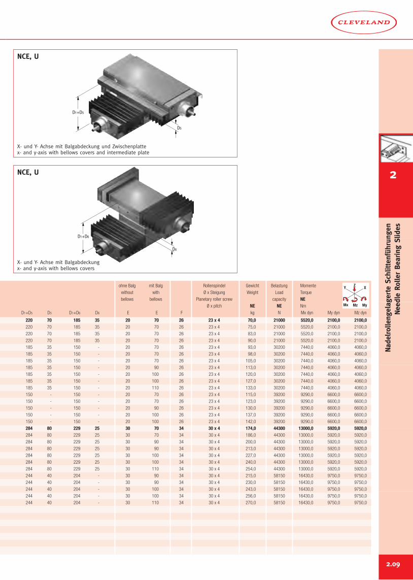
X- und Y- Achse mit Balgabdeckung und Zwischenplattex- and y-axis with bellows covers and intermediate plate
NCE, U
NCE, U
ohne Balg mit Balg Rollenspindel Gewicht Belastung Momente
without with Ø x Steigung Weight Load Torque
bellows bellows Planetary roller screw capacity NEØ x pitch NE NE Nm
D1+D5 D5 D1+D6 D6 E E F kg N Mx dyn My dyn Mz dyn
Y X
MyMz
Z
Mx
X- und Y- Achse mit Balgabdeckungx- and y-axis with bellows covers
2.09
2
NadelrollengelagerteSchlittenführungen
NeedleRollerBearing
Slides
2.10
E
BD
B1
A
F
E
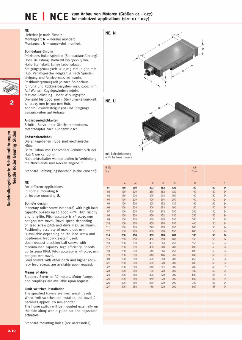
NE, NNELieferbar je nach EinsatzMontageart N = normal montiertMontageart U = umgekehrt montiert.
SpindelausführungPräzisions-Rollenspindeln (Standardausführung).Hohe Belastung. Drehzahl bis 3000 1/min.Hohe Steifigkeit. Lange Lebensdauer.Steigungsgenauigkeit +/- 0,015 mm je 300 mmHub. Verfahrgeschwindigkeit je nach Spindel-steigung und Antrieb max. 20 m/min.Positioniergenauigkeit je nach Spindelaus-führung und Rückmeldesystem max. 0,001 mm.Auf Wunsch Kugelgewindespindeln.Mittlere Belastung. Hoher Wirkungsgrad.Drehzahl bis 2000 1/min. Steigungsgenauigkeit+/- 0,015 mm je 300 mm Hub.Andere Gewindesteigungen und Steigungs-genauigkeiten auf Anfrage.
AntriebsmöglichkeitenSchritt-, Servo- oder Gleichstrommotoren.Motoradapter nach Kundenwunsch.
EndschaltereinbauDie angegebenen Hübe sind mechanischeHübe.Beim Einbau von Endschalter verkürzt sich derHub C um ca. 20 mm.Nullpunktschalter werden außen in Verbindungmit Nutenleiste und Nocken angebaut.
Standard Befestigungsbohrbild (siehe Zubehör).
NEFor different applicationsin normal mounting Nor inverse mounting U.
Spindle designPlanetary roller screw (standard) with high-loadcapacity, Speeds up to 3000 RPM. High rigidityand long-life. Pitch accuracy is +/- 0,015 mmper 300 mm travel. Travel speed dependingon lead screw pitch and drive max. 20 m/min.Positioning accuracy of max. 0,001 mmis available depending on the lead screw andpositioning feedback system used.Upon request precision ball screws withmedium-load capacity, high efficiency. Speedsup to 2000 RPM. Pitch accuracy is +/- 0,015 mmper 300 mm travel.Lead screws with other pitch and higher accu-racy lead screws are available upon request.
Means of driveStepper-, Servo- or AC-motors. Motor flangesand couplings are available upon request.
Limit switches installationThe specified travels are mechanical travels.When limit switches are installed, the travel Cbecomes approx. 20 mm shorter.The home switch will be mounted externally onthe side along with a guide bar and adjustableactuators.
Standard mounting holes (see accessories).
NE | NCE zum Anbau von Motoren (Größen 01 - 027)for motorized applications (size 01 - 027)
01 150 200 203 152 120 50 50 2402 150 200 285 152 120 100 50 24
03 150 200 305 203 150 100 50 24
04 150 200 406 304 250 100 50 24
05 150 200 305 152 130 150 50 24
06 150 200 406 253 190 150 50 24
07 150 200 406 203 150 200 50 24
08 150 200 406 152 130 250 50 24
09 150 200 530 203 150 300 50 24
010 150 200 650 203 150 400 50 24
011 150 200 770 203 150 500 50 24
012 150 200 880 203 150 600 50 24
014 200 250 335 220 200 100 58 24015 200 250 406 253 200 150 58 24
016 200 250 457 304 250 150 58 24
017 200 250 460 220 200 200 58 24
018 200 250 510 304 250 200 58 24
019 200 250 610 406 350 200 58 24
020 200 250 520 253 200 250 58 24
021 200 250 580 220 200 300 58 24
022 200 250 610 304 200 300 58 24
023 200 250 700 220 200 400 58 24
024 200 250 820 220 200 500 58 24
025 200 250 940 220 200 600 58 24
026 200 250 1070 220 200 700 58 24
027 200 250 1185 220 200 800 58 24
Größe Hub
Size Travel
A A1 B B1 B2 C D D2
B2
D2
NE, U
mit Balgabdeckungwith bellows covers
NadelrollengelagerteSchlittenführungen
NeedleRollerBearing
Slides
2
2.11
B2
A1
mit Balgabdeckungwith bellows covers
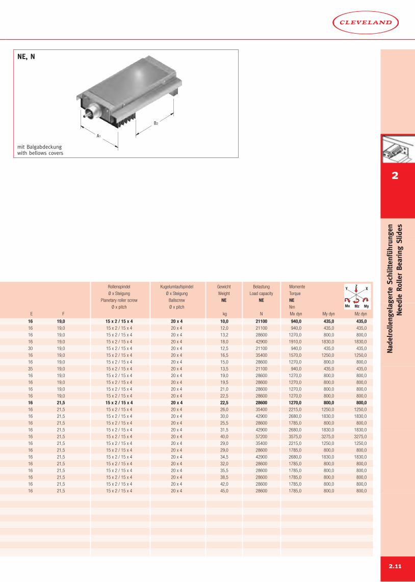
NE, N
16 19,0 15 x 2 / 15 x 4 20 x 4 10,0 21100 940,0 435,0 435,016 19,0 15 x 2 / 15 x 4 20 x 4 12,0 21100 940,0 435,0 435,0
16 19,0 15 x 2 / 15 x 4 20 x 4 13,2 28600 1270,0 800,0 800,0
16 19,0 15 x 2 / 15 x 4 20 x 4 18,0 42900 1910,0 1830,0 1830,0
30 19,0 15 x 2 / 15 x 4 20 x 4 12,5 21100 940,0 435,0 435,0
16 19,0 15 x 2 / 15 x 4 20 x 4 16,5 35400 1570,0 1250,0 1250,0
16 19,0 15 x 2 / 15 x 4 20 x 4 15,0 28600 1270,0 800,0 800,0
35 19,0 15 x 2 / 15 x 4 20 x 4 13,5 21100 940,0 435,0 435,0
16 19,0 15 x 2 / 15 x 4 20 x 4 19,0 28600 1270,0 800,0 800,0
16 19,0 15 x 2 / 15 x 4 20 x 4 19,5 28600 1270,0 800,0 800,0
16 19,0 15 x 2 / 15 x 4 20 x 4 21,0 28600 1270,0 800,0 800,0
16 19,0 15 x 2 / 15 x 4 20 x 4 22,5 28600 1270,0 800,0 800,0
16 21,5 15 x 2 / 15 x 4 20 x 4 22,5 28600 1270,0 800,0 800,016 21,5 15 x 2 / 15 x 4 20 x 4 26,0 35400 2215,0 1250,0 1250,0
16 21,5 15 x 2 / 15 x 4 20 x 4 30,0 42900 2680,0 1830,0 1830,0
16 21,5 15 x 2 / 15 x 4 20 x 4 25,5 28600 1785,0 800,0 800,0
16 21,5 15 x 2 / 15 x 4 20 x 4 31,5 42900 2680,0 1830,0 1830,0
16 21,5 15 x 2 / 15 x 4 20 x 4 40,0 57200 3575,0 3275,0 3275,0
16 21,5 15 x 2 / 15 x 4 20 x 4 29,0 35400 2215,0 1250,0 1250,0
16 21,5 15 x 2 / 15 x 4 20 x 4 29,0 28600 1785,0 800,0 800,0
16 21,5 15 x 2 / 15 x 4 20 x 4 34,5 42900 2680,0 1830,0 1830,0
16 21,5 15 x 2 / 15 x 4 20 x 4 32,0 28600 1785,0 800,0 800,0
16 21,5 15 x 2 / 15 x 4 20 x 4 35,5 28600 1785,0 800,0 800,0
16 21,5 15 x 2 / 15 x 4 20 x 4 38,5 28600 1785,0 800,0 800,0
16 21,5 15 x 2 / 15 x 4 20 x 4 42,0 28600 1785,0 800,0 800,0
16 21,5 15 x 2 / 15 x 4 20 x 4 45,0 28600 1785,0 800,0 800,0
Rollenspindel Kugelumlaufspindel Gewicht Belastung Momente
Ø x Steigung Ø x Steigung Weight Load capacity Torque
Planetary roller screw Ballscrew NE NE NEØ x pitch Ø x pitch Nm
E F kg N Mx dyn My dyn Mz dyn
Y X
MyMz
Z
Mx
2
NadelrollengelagerteSchlittenführungen
NeedleRollerBearing
Slides
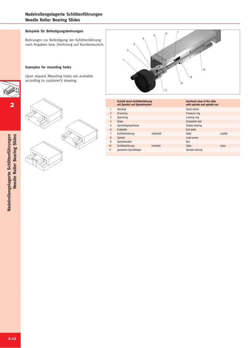
Nadelrollengelagerte SchlittenführungenNeedle Roller Bearing Slides
Beispiele für Befestigungsbohrungen
Bohrungen zur Befestigung der Schlittenführungnach Angaben bzw. Zeichnung auf Kundenwunsch.
Examples for mounting holes
Upon request Mounting holes are availableaccording to customer’s drawing.
10
9
8
765
4
3
2
11
1
1 Handrad Hand-wheel2 Druckring Pressure ring3 Spannring Locking ring4 Skala Graduated dial5 Spindellagergehäuse Duplex bearing6 Endplatte End plate7 Schlittenführung Außenteil Slide saddle8 Spindel Lead screw9 Spindelmutter Nut
10 Schlittenführung Innenteil Slide base11 gepaartes Spindellager Spindle bearing
Schnitt durch Schlittenführung Sectional view of the slidemit Spindel und Spindelmutter with spindle and spindle nut
2.12
NadelrollengelagerteSchlittenführungen
NeedleRollerBearing
Slides
2
Schwalbenschwanz SchlittenführungenDovetail Slides
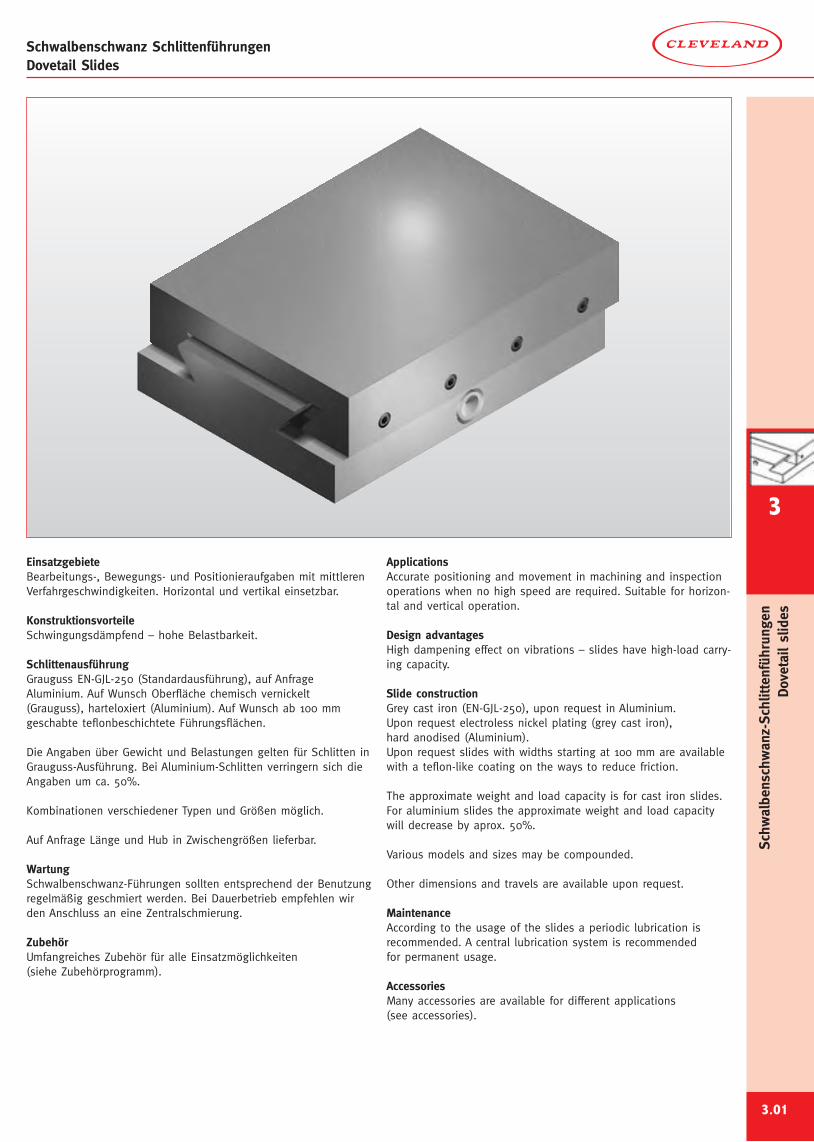
EinsatzgebieteBearbeitungs-, Bewegungs- und Positionieraufgaben mit mittlerenVerfahrgeschwindigkeiten. Horizontal und vertikal einsetzbar.
KonstruktionsvorteileSchwingungsdämpfend – hohe Belastbarkeit.
SchlittenausführungGrauguss EN-GJL-250 (Standardausführung), auf AnfrageAluminium. Auf Wunsch Oberfläche chemisch vernickelt(Grauguss), harteloxiert (Aluminium). Auf Wunsch ab 100 mmgeschabte teflonbeschichtete Führungsflächen.
Die Angaben über Gewicht und Belastungen gelten für Schlitten inGrauguss-Ausführung. Bei Aluminium-Schlitten verringern sich dieAngaben um ca. 50%.
Kombinationen verschiedener Typen und Größen möglich.
Auf Anfrage Länge und Hub in Zwischengrößen lieferbar.
WartungSchwalbenschwanz-Führungen sollten entsprechend der Benutzungregelmäßig geschmiert werden. Bei Dauerbetrieb empfehlen wirden Anschluss an eine Zentralschmierung.
ZubehörUmfangreiches Zubehör für alle Einsatzmöglichkeiten(siehe Zubehörprogramm).
ApplicationsAccurate positioning and movement in machining and inspectionoperations when no high speed are required. Suitable for horizon-tal and vertical operation.
Design advantagesHigh dampening effect on vibrations – slides have high-load carry-ing capacity.
Slide constructionGrey cast iron (EN-GJL-250), upon request in Aluminium.Upon request electroless nickel plating (grey cast iron),hard anodised (Aluminium).Upon request slides with widths starting at 100 mm are availablewith a teflon-like coating on the ways to reduce friction.
The approximate weight and load capacity is for cast iron slides.For aluminium slides the approximate weight and load capacitywill decrease by aprox. 50%.
Various models and sizes may be compounded.
Other dimensions and travels are available upon request.
MaintenanceAccording to the usage of the slides a periodic lubrication isrecommended. A central lubrication system is recommendedfor permanent usage.
AccessoriesMany accessories are available for different applications(see accessories).
3.01
Schw
albenschwanz-Schlittenführungen
Dovetailslides
3
Schwalbenschwanz SchlittenführungenDovetail Slides
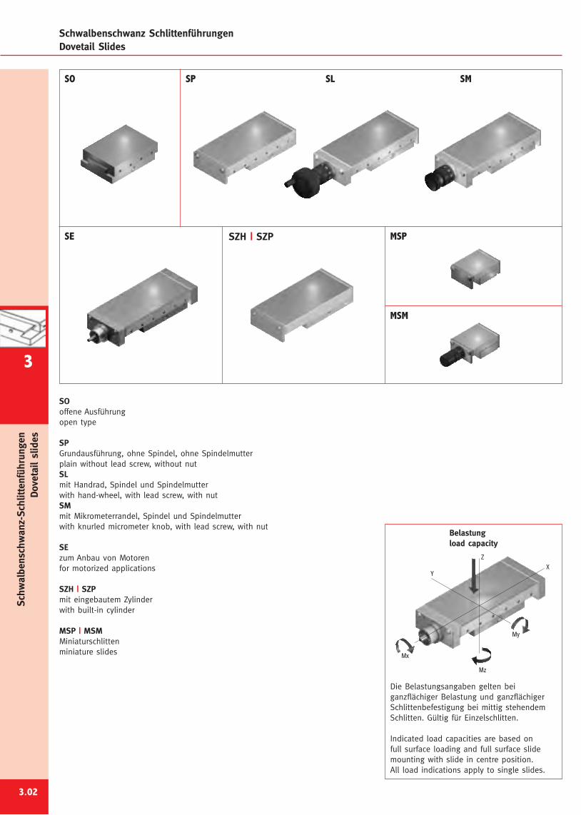
SOoffene Ausführungopen type
SPGrundausführung, ohne Spindel, ohne Spindelmutterplain without lead screw, without nutSLmit Handrad, Spindel und Spindelmutterwith hand-wheel, with lead screw, with nutSMmit Mikrometerrandel, Spindel und Spindelmutterwith knurled micrometer knob, with lead screw, with nut
SEzum Anbau von Motorenfor motorized applications
SZH | SZPmit eingebautem Zylinderwith built-in cylinder
MSP | MSMMiniaturschlittenminiature slides
3.02
SO SP SL SM
SE SZH | SZP MSP
MSM
Z
Mx
Mz
My
YX
Belastungload capacity
Die Belastungsangaben gelten beiganzflächiger Belastung und ganzflächigerSchlittenbefestigung bei mittig stehendemSchlitten. Gültig für Einzelschlitten.
Indicated load capacities are based onfull surface loading and full surface slidemounting with slide in centre position.All load indications apply to single slides.
Schw
albenschwanz-Schlittenführungen
Dovetailslides
3
E
F
BA
D
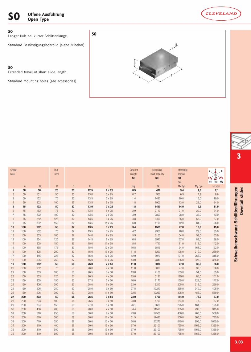
SOLanger Hub bei kurzer Schlittenlänge.
Standard Besfestigungsbohrbild (siehe Zubehör).
SOExtended travel at short slide length.
Standard mounting holes (see accessories).
SO Offene AusführungOpen Type
3.03
Größe Hub Gewicht Belastung Momente
Size Travel Weight Load capacity Torque
SO SO SONm
A B C D E F kg N Mx dyn My dyn Mz dyn
SO
Y X
MyMz
Z
Mx
1 50 50 25 25 12,5 1 x 25 0,5 470 3,4 1,8 2,12 50 101 50 25 13,0 3 x 25 0,7 950 6,9 7,2 8,6
3 50 152 75 25 13,5 5 x 25 1,4 1430 10,0 16,0 19,0
4 50 202 100 25 13,5 7 x 25 1,8 1900 13,0 29,0 34,0
5 75 102 50 32 13,0 3 x 25 1,8 1410 14,0 9,2 11,06 75 152 75 32 13,5 5 x 25 2,9 2110 21,0 20,0 24,0
7 75 202 100 32 13,5 7 x 25 3,9 2800 28,0 36,0 43,0
8 75 252 125 32 13,5 9 x 25 4,8 3490 35,0 56,0 67,0
9 75 302 150 32 13,5 11 x 25 6,0 4190 42,0 81,0 96,0
10 100 102 50 37 13,5 3 x 25 3,4 1585 27,0 13,0 15,011 100 152 75 37 13,5 5 x 25 4,2 2360 40,0 29,0 35,0
12 100 203 100 37 14,0 7 x 25 5,9 3155 54,0 52,0 63,0
13 100 254 125 37 14,5 9 x 25 6,8 3940 67,0 82,0 98,0
14 100 305 150 37 15,0 11 x 25 8,8 4740 81,0 119,0 142,0
15 100 355 175 37 15,0 13 x 25 10,5 5515 94,0 161,0 192,0
16 100 405 200 37 15,0 15 x 25 11,8 6290 108,0 210,0 250,0
17 100 445 225 37 15,0 17 x 25 12,9 7070 121,0 265,0 315,0
18 100 505 250 37 15,0 19 x 25 14,0 7840 135,0 325,0 385,0
19 150 152 50 50 26,0 2 x 50 11,0 3070 77,0 30,0 36,020 150 152 75 50 26,0 2 x 50 11,0 3070 77,0 30,0 36,0
21 150 203 100 50 26,5 3 x 50 13,8 4100 103,0 54,0 65,0
22 150 253 125 50 26,5 4 x 50 15,0 5120 129,0 85,0 101,0
23 150 305 150 50 27,5 5 x 50 16,0 6170 155,0 123,0 147,0
24 150 406 200 50 28,0 7 x 50 22,0 8210 205,0 219,0 260,0
25 150 506 250 50 28,0 9 x 50 27,5 10240 255,0 340,0 405,0
26 150 606 300 50 28,0 11 x 50 32,5 12260 305,0 485,0 580,0
27 200 203 50 58 26,5 3 x 50 23,0 5790 184,0 73,0 87,028 200 203 100 58 26,5 3 x 50 23,0 5790 184,0 73,0 87,0
29 200 304 150 58 27,0 5 x 50 26,1 8680 275,0 164,0 195,0
30 200 406 200 58 28,0 7 x 50 34,4 11590 365,0 290,0 345,0
31 200 510 250 58 30,0 9 x 50 43,0 14560 460,0 460,0 550,0
32 200 610 300 58 30,0 11 x 50 51,5 17420 550,0 660,0 785,0
33 200 710 350 58 30,0 13 x 50 60,0 20270 645,0 895,0 1065,0
34 200 810 400 58 30,0 15 x 50 67,0 23100 735,0 1165,0 1385,0
35 200 810 500 58 30,0 15 x 50 67,0 23100 735,0 1165,0 1385,0
36 200 810 600 58 30,0 15 x 50 67,0 23100 735,0 1165,0 1385,0
Schw
albenschwanz-Schlittenführungen
Dovetailslides
3
E2
F2
K
G1
øH1
E1
F1
B
F1
B1
CA
D1
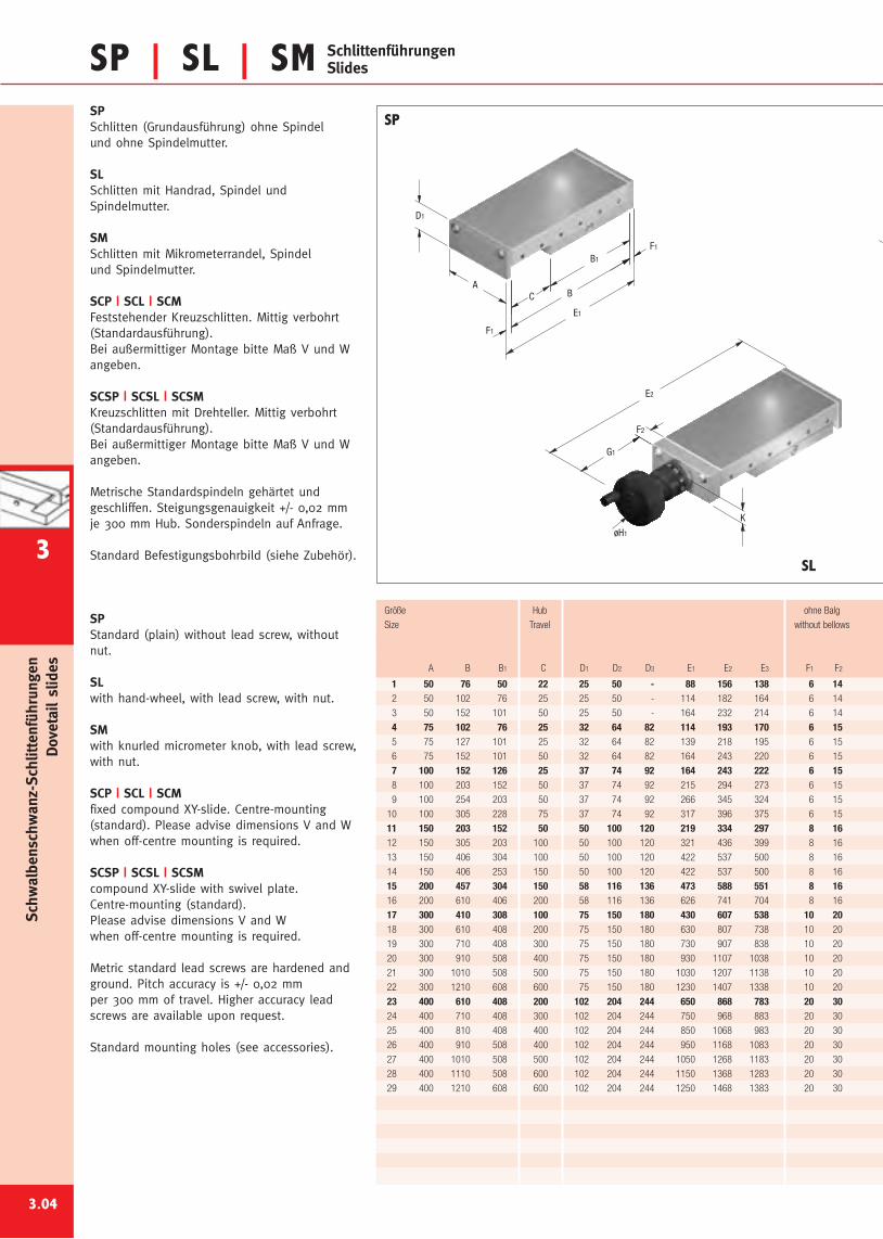
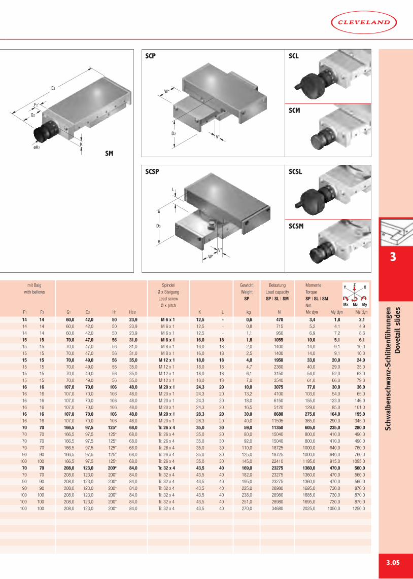
SP | SL | SM SchlittenführungenSlides
SPSchlitten (Grundausführung) ohne Spindelund ohne Spindelmutter.
SLSchlitten mit Handrad, Spindel undSpindelmutter.
SMSchlitten mit Mikrometerrandel, Spindelund Spindelmutter.
SCP | SCL | SCMFeststehender Kreuzschlitten. Mittig verbohrt(Standardausführung).Bei außermittiger Montage bitte Maß V und Wangeben.
SCSP | SCSL | SCSMKreuzschlitten mit Drehteller. Mittig verbohrt(Standardausführung).Bei außermittiger Montage bitte Maß V und Wangeben.
Metrische Standardspindeln gehärtet undgeschliffen. Steigungsgenauigkeit +/- 0,02 mmje 300 mm Hub. Sonderspindeln auf Anfrage.
Standard Befestigungsbohrbild (siehe Zubehör).
SPStandard (plain) without lead screw, withoutnut.
SLwith hand-wheel, with lead screw, with nut.
SMwith knurled micrometer knob, with lead screw,with nut.
SCP | SCL | SCMfixed compound XY-slide. Centre-mounting(standard). Please advise dimensions V and Wwhen off-centre mounting is required.
SCSP | SCSL | SCSMcompound XY-slide with swivel plate.Centre-mounting (standard).Please advise dimensions V and Wwhen off-centre mounting is required.
Metric standard lead screws are hardened andground. Pitch accuracy is +/- 0,02 mmper 300 mm of travel. Higher accuracy leadscrews are available upon request.
Standard mounting holes (see accessories).
3.04
SP
SL
1 50 76 50 22 25 50 - 88 156 138 6 142 50 102 76 25 25 50 - 114 182 164 6 14
3 50 152 101 50 25 50 - 164 232 214 6 14
4 75 102 76 25 32 64 82 114 193 170 6 155 75 127 101 25 32 64 82 139 218 195 6 15
6 75 152 101 50 32 64 82 164 243 220 6 15
7 100 152 126 25 37 74 92 164 243 222 6 158 100 203 152 50 37 74 92 215 294 273 6 15
9 100 254 203 50 37 74 92 266 345 324 6 15
10 100 305 228 75 37 74 92 317 396 375 6 15
11 150 203 152 50 50 100 120 219 334 297 8 1612 150 305 203 100 50 100 120 321 436 399 8 16
13 150 406 304 100 50 100 120 422 537 500 8 16
14 150 406 253 150 50 100 120 422 537 500 8 16
15 200 457 304 150 58 116 136 473 588 551 8 1616 200 610 406 200 58 116 136 626 741 704 8 16
17 300 410 308 100 75 150 180 430 607 538 10 2018 300 610 408 200 75 150 180 630 807 738 10 20
19 300 710 408 300 75 150 180 730 907 838 10 20
20 300 910 508 400 75 150 180 930 1107 1038 10 20
21 300 1010 508 500 75 150 180 1030 1207 1138 10 20
22 300 1210 608 600 75 150 180 1230 1407 1338 10 20
23 400 610 408 200 102 204 244 650 868 783 20 3024 400 710 408 300 102 204 244 750 968 883 20 30
25 400 810 408 400 102 204 244 850 1068 983 20 30
26 400 910 508 400 102 204 244 950 1168 1083 20 30
27 400 1010 508 500 102 204 244 1050 1268 1183 20 30
28 400 1110 508 600 102 204 244 1150 1368 1283 20 30
29 400 1210 608 600 102 204 244 1250 1468 1383 20 30
Größe Hub ohne Balg
Size Travel without bellows
A B B1 C D1 D2 D3 E1 E2 E3 F1 F2
Schw
albenschwanz-Schlittenführungen
Dovetailslides
3
E3
F2
K
G2
øH2
3.05
W*
L
V*
D3
D2
W*
V*
SCP SCL
SCM
SCSL
SCSM
SM
SCSP
14 14 60,0 42,0 50 23,9 M 6 x 1 12,5 - 0,6 470 3,4 1,8 2,114 14 60,0 42,0 50 23,9 M 6 x 1 12,5 - 0,8 715 5,2 4,1 4,9
14 14 60,0 42,0 50 23,9 M 6 x 1 12,5 - 1,1 950 6,9 7,2 8,6
15 15 70,0 47,0 56 31,0 M 8 x 1 16,0 18 1,8 1055 10,0 5,1 6,115 15 70,0 47,0 56 31,0 M 8 x 1 16,0 18 2,0 1400 14,0 9,1 10,0
15 15 70,0 47,0 56 31,0 M 8 x 1 16,0 18 2,5 1400 14,0 9,1 10,0
15 15 70,0 49,0 56 35,0 M 12 x 1 18,0 18 4,0 1950 33,0 20,0 24,015 15 70,0 49,0 56 35,0 M 12 x 1 18,0 18 4,7 2360 40,0 29,0 35,0
15 15 70,0 49,0 56 35,0 M 12 x 1 18,0 18 6,1 3150 54,0 52,0 63,0
15 15 70,0 49,0 56 35,0 M 12 x 1 18,0 18 7,0 3540 61,0 66,0 79,0
16 16 107,0 70,0 106 48,0 M 20 x 1 24,3 20 10,0 3075 77,0 30,0 36,016 16 107,0 70,0 106 48,0 M 20 x 1 24,3 20 13,2 4100 103,0 54,0 65,0
16 16 107,0 70,0 106 48,0 M 20 x 1 24,3 20 18,0 6150 155,0 123,0 146,0
16 16 107,0 70,0 106 48,0 M 20 x 1 24,3 20 16,5 5120 129,0 85,0 101,0
16 16 107,0 70,0 106 48,0 M 20 x 1 28,3 20 30,0 8680 275,0 164,0 195,016 16 107,0 70,0 106 48,0 M 20 x 1 28,3 20 40,0 11595 365,0 290,0 345,0
70 70 166,5 97,5 125* 68,0 Tr. 26 x 4 35,0 30 59,0 11350 605,0 235,0 280,070 70 166,5 97,5 125* 68,0 Tr. 26 x 4 35,0 30 80,0 15040 800,0 410,0 490,0
70 70 166,5 97,5 125* 68,0 Tr. 26 x 4 35,0 30 92,0 15040 800,0 410,0 490,0
70 70 166,5 97,5 125* 68,0 Tr. 26 x 4 35,0 30 110,0 18725 1000,0 640,0 760,0
90 90 166,5 97,5 125* 68,0 Tr. 26 x 4 35,0 30 125,0 18725 1000,0 640,0 760,0
100 100 166,5 97,5 125* 68,0 Tr. 26 x 4 35,0 30 145,0 22410 1195,0 915,0 1095,0
70 70 208,0 123,0 200* 84,0 Tr. 32 x 4 43,5 40 169,0 23275 1360,0 470,0 560,070 70 208,0 123,0 200* 84,0 Tr. 32 x 4 43,5 40 182,0 23275 1360,0 470,0 560,0
90 90 208,0 123,0 200* 84,0 Tr. 32 x 4 43,5 40 195,0 23275 1360,0 470,0 560,0
90 90 208,0 123,0 200* 84,0 Tr. 32 x 4 43,5 40 225,0 28980 1695,0 730,0 870,0
100 100 208,0 123,0 200* 84,0 Tr. 32 x 4 43,5 40 238,0 28980 1685,0 730,0 870,0
100 100 208,0 123,0 200* 84,0 Tr. 32 x 4 43,5 40 251,0 28980 1695,0 730,0 870,0
100 100 208,0 123,0 200* 84,0 Tr. 32 x 4 43,5 40 270,0 34680 2025,0 1050,0 1250,0
mit Balg Spindel Gewicht Belastung Momente
with bellows Ø x Steigung Weight Load capacity Torque
Lead screw SP SP | SL | SM SP | SL | SMØ x pitch Nm
F1 F2 G1 G2 H1 H2Ø K L kg N Mx dyn My dyn Mz dyn
Y X
MyMz
Z
Mx
Schw
albenschwanz-Schlittenführungen
Dovetailslides
3
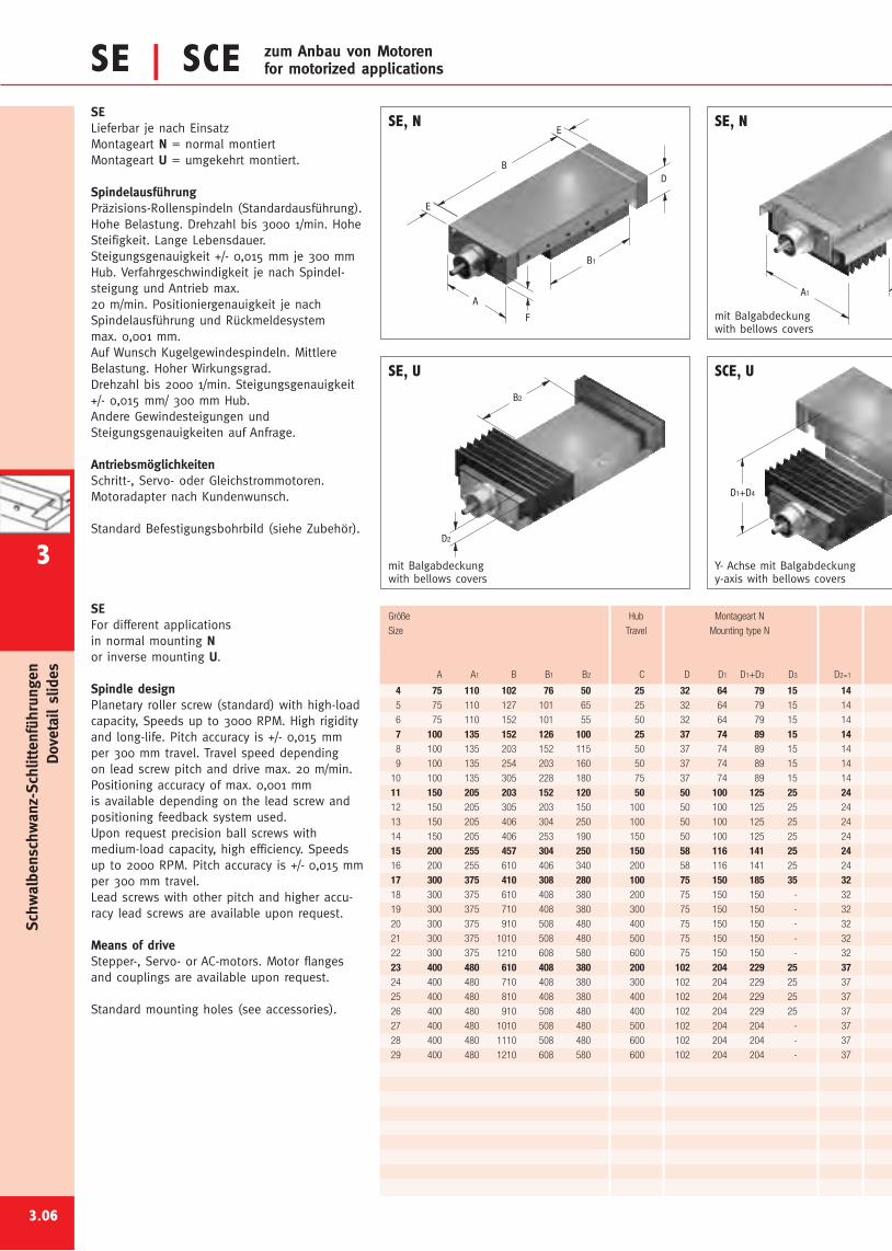
E
BD
B1
A
F
E
A1
B2
D2
D1+D4
SE | SCE zum Anbau von Motorenfor motorized applications
4 75 110 102 76 50 25 32 64 79 15 145 75 110 127 101 65 25 32 64 79 15 14
6 75 110 152 101 55 50 32 64 79 15 14
7 100 135 152 126 100 25 37 74 89 15 148 100 135 203 152 115 50 37 74 89 15 14
9 100 135 254 203 160 50 37 74 89 15 14
10 100 135 305 228 180 75 37 74 89 15 14
11 150 205 203 152 120 50 50 100 125 25 2412 150 205 305 203 150 100 50 100 125 25 24
13 150 205 406 304 250 100 50 100 125 25 24
14 150 205 406 253 190 150 50 100 125 25 24
15 200 255 457 304 250 150 58 116 141 25 2416 200 255 610 406 340 200 58 116 141 25 24
17 300 375 410 308 280 100 75 150 185 35 3218 300 375 610 408 380 200 75 150 150 - 32
19 300 375 710 408 380 300 75 150 150 - 32
20 300 375 910 508 480 400 75 150 150 - 32
21 300 375 1010 508 480 500 75 150 150 - 32
22 300 375 1210 608 580 600 75 150 150 - 32
23 400 480 610 408 380 200 102 204 229 25 3724 400 480 710 408 380 300 102 204 229 25 37
25 400 480 810 408 380 400 102 204 229 25 37
26 400 480 910 508 480 400 102 204 229 25 37
27 400 480 1010 508 480 500 102 204 204 - 37
28 400 480 1110 508 480 600 102 204 204 - 37
29 400 480 1210 608 580 600 102 204 204 - 37
SELieferbar je nach EinsatzMontageart N = normal montiertMontageart U = umgekehrt montiert.
SpindelausführungPräzisions-Rollenspindeln (Standardausführung).Hohe Belastung. Drehzahl bis 3000 1/min. HoheSteifigkeit. Lange Lebensdauer.Steigungsgenauigkeit +/- 0,015 mm je 300 mmHub. Verfahrgeschwindigkeit je nach Spindel-steigung und Antrieb max.20 m/min. Positioniergenauigkeit je nachSpindelausführung und Rückmeldesystemmax. 0,001 mm.Auf Wunsch Kugelgewindespindeln. MittlereBelastung. Hoher Wirkungsgrad.Drehzahl bis 2000 1/min. Steigungsgenauigkeit+/- 0,015 mm/ 300 mm Hub.Andere Gewindesteigungen undSteigungsgenauigkeiten auf Anfrage.
AntriebsmöglichkeitenSchritt-, Servo- oder Gleichstrommotoren.Motoradapter nach Kundenwunsch.
Standard Befestigungsbohrbild (siehe Zubehör).
SEFor different applicationsin normal mounting Nor inverse mounting U.
Spindle designPlanetary roller screw (standard) with high-loadcapacity, Speeds up to 3000 RPM. High rigidityand long-life. Pitch accuracy is +/- 0,015 mmper 300 mm travel. Travel speed dependingon lead screw pitch and drive max. 20 m/min.Positioning accuracy of max. 0,001 mmis available depending on the lead screw andpositioning feedback system used.Upon request precision ball screws withmedium-load capacity, high efficiency. Speedsup to 2000 RPM. Pitch accuracy is +/- 0,015 mmper 300 mm travel.Lead screws with other pitch and higher accu-racy lead screws are available upon request.
Means of driveStepper-, Servo- or AC-motors. Motor flangesand couplings are available upon request.
Standard mounting holes (see accessories).
3.06
mit Balgabdeckungwith bellows covers
Y- Achse mit Balgabdeckungy-axis with bellows covers
SCE, USE, U
Größe Hub Montageart N
Size Travel Mounting type N
A A1 B B1 B2 C D D1 D1+D3 D3 D2=1
SE, NSE, N
mit Balgabdeckungwith bellows covers
Schw
albenschwanz-Schlittenführungen
Dovetailslides
3
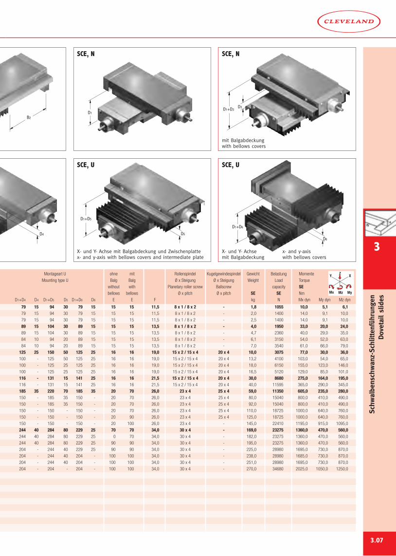
B2
D1
D3D1+D3
D4 D5
D1+D5
D6
D1+D6
79 15 94 30 79 15 15 15 11,5 8 x 1 / 8 x 2 - 1,8 1055 10,0 5,1 6,179 15 94 30 79 15 15 15 11,5 8 x 1 / 8 x 2 - 2,0 1400 14,0 9,1 10,0
79 15 94 30 79 15 15 15 11,5 8 x 1 / 8 x 2 - 2,5 1400 14,0 9,1 10,0
89 15 104 30 89 15 15 15 13,5 8 x 1 / 8 x 2 - 4,0 1950 33,0 20,0 24,089 15 104 30 89 15 15 15 13,5 8 x 1 / 8 x 2 - 4,7 2360 40,0 29,0 35,0
84 10 94 20 89 15 15 15 13,5 8 x 1 / 8 x 2 - 6,1 3150 54,0 52,0 63,0
84 10 94 20 89 15 15 15 13,5 8 x 1 / 8 x 2 - 7,0 3540 61,0 66,0 79,0
125 25 150 50 125 25 16 16 19,0 15 x 2 / 15 x 4 20 x 4 10,0 3075 77,0 30,0 36,0100 - 125 50 125 25 16 16 19,0 15 x 2 / 15 x 4 20 x 4 13,2 4100 103,0 54,0 65,0
100 - 125 25 125 25 16 16 19,0 15 x 2 / 15 x 4 20 x 4 18,0 6150 155,0 123,0 146,0
100 - 125 25 125 25 16 16 19,0 15 x 2 / 15 x 4 20 x 4 16,5 5120 129,0 85,0 101,0
116 - 131 15 141 25 16 16 21,5 15 x 2 / 15 x 4 20 x 4 30,0 8680 275,0 164,0 195,0116 - 131 15 141 25 16 16 21,5 15 x 2 / 15 x 4 20 x 4 40,0 11595 365,0 290,0 345,0
185 35 220 70 185 35 20 70 26,0 23 x 4 25 x 4 59,0 11350 605,0 235,0 280,0150 - 185 35 150 - 20 70 26,0 23 x 4 25 x 4 80,0 15040 800,0 410,0 490,0
150 - 185 35 150 - 20 70 26,0 23 x 4 25 x 4 92,0 15040 800,0 410,0 490,0
150 - 150 - 150 - 20 70 26,0 23 x 4 25 x 4 110,0 18725 1000,0 640,0 760,0
150 - 150 - 150 - 20 90 26,0 23 x 4 25 x 4 125,0 18725 1000,0 640,0 760,0
150 - 150 - 150 - 20 100 26,0 23 x 4 - 145,0 22410 1195,0 915,0 1095,0
244 40 284 80 229 25 70 70 34,0 30 x 4 - 169,0 23275 1360,0 470,0 560,0244 40 284 80 229 25 0 70 34,0 30 x 4 - 182,0 23275 1360,0 470,0 560,0
244 40 284 80 229 25 90 90 34,0 30 x 4 - 195,0 23275 1360,0 470,0 560,0
204 - 244 40 229 25 90 90 34,0 30 x 4 - 225,0 28980 1695,0 730,0 870,0
204 - 244 40 204 - 100 100 34,0 30 x 4 - 238,0 28980 1685,0 730,0 870,0
204 - 244 40 204 - 100 100 34,0 30 x 4 - 251,0 28980 1695,0 730,0 870,0
204 - 204 - 204 - 100 100 34,0 30 x 4 - 270,0 34680 2025,0 1050,0 1250,0
3.07
mit Balgabdeckungwith bellows covers
X- und Y- Achse mit Balgabdeckung und Zwischenplattex- and y-axis with bellows covers and intermediate plate
X- und Y- Achsemit Balgabdeckung
x- and y-axiswith bellows covers
SCE, U SCE, U
Montageart U ohne mit Rollenspindel Kugelgewindespindel Gewicht Belastung Momente
Mounting type U Balg Balg Ø x Steigung Ø x Steigung Weight Load Torque
without with Planetary roller screw Ballscrew capacity SEbellows bellows Ø x pitch Ø x pitch SE SE Nm
D1+D4 D4 D1+D5 D5 D1+D6 D6 E E F kg N Mx dyn My dyn Mz dyn
SCE, N SCE, N
Y X
MyMz
Z
Mx
Schw
albenschwanz-Schlittenführungen
Dovetailslides
3
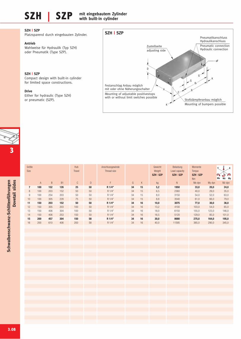
SZH | SZPSZH | SZPPlatzsparend durch eingebauten Zylinder.
AntriebWahlweise für Hydraulik (Typ SZH)oder Pneumatik (Type SZP).
SZH | SZPCompact design with built-in cylinderfor limited space constructions.
DriveEither for hydraulic (Type SZH)or pneumatic (SZP).
Mounting of bumpers possible
Mounting of adjustable positivestopswith or without limit switches possible
adjusting side
Pneumatic connectionHydraulic connection
PneumatikanschlussHydraulikanschluss
Stoßdämpferanbau möglich
Festanschlag Anbau möglichmit oder ohne Näherungsschalter
Zustellseite
ØF
B
K
K
B1
G
G
CA
D
SZH | SZP
3.08
7 100 152 126 25 50 R 1/4’’ 34 15 5,2 1950 33,0 20,0 24,08 100 203 152 50 50 R 1/4’’ 34 15 6,5 2360 40,0 29,0 35,0
9 100 254 203 50 50 R 1/4’’ 34 15 8,0 3150 54,0 52,0 63,0
10 100 305 228 75 50 R 1/4’’ 34 15 8,8 3540 61,0 66,0 79,0
11 150 203 152 50 50 R 1/4’’ 34 16 10,0 3075 77,0 30,0 36,012 150 305 203 100 50 R 1/4’’ 34 16 13,2 4100 103,0 54,0 65,0
13 150 406 304 100 50 R 1/4’’ 34 16 18,0 6150 155,0 123,0 146,0
14 150 406 253 150 50 R 1/4’’ 34 16 16,5 5120 129,0 85,0 101,0
15 200 457 304 150 58 R 1/4’’ 34 16 30,0 8680 275,0 164,0 195,016 200 610 406 200 58 R 1/4’’ 34 16 40,0 11595 365,0 290,0 345,0
Größe Hub Anschlussgewinde Gewicht Belastung Momente
Size Travel Thread size Weight Load capacity Torque
SZH | SZP SZH | SZP SZH | SZPNm
A B B1 C D F G K kg N Mx dyn My dyn Mz dyn
Y X
MyMz
Z
Mx
mit eingebautem Zylinderwith built-in cylinder
Schw
albenschwanz-Schlittenführungen
Dovetailslides
3
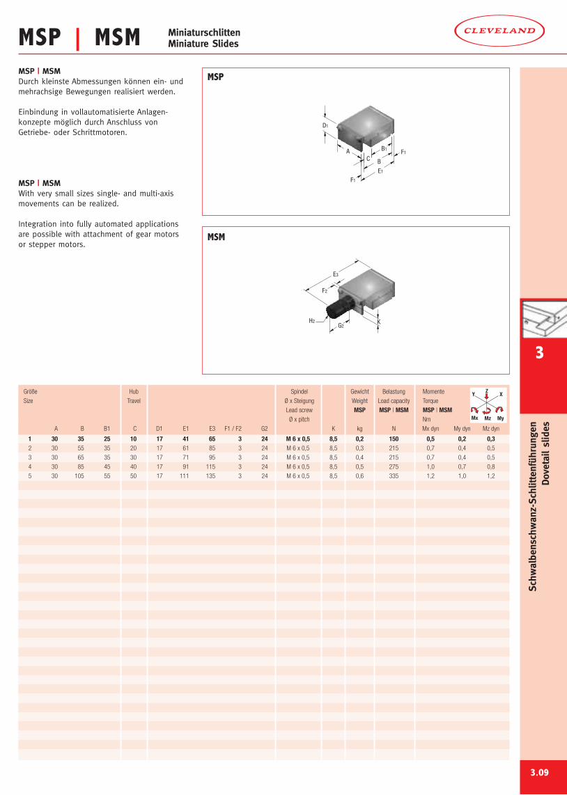
MSP | MSMMSP | MSMDurch kleinste Abmessungen können ein- undmehrachsige Bewegungen realisiert werden.
Einbindung in vollautomatisierte Anlagen-konzepte möglich durch Anschluss vonGetriebe- oder Schrittmotoren.
MSP | MSMWith very small sizes single- and multi-axismovements can be realized.
Integration into fully automated applicationsare possible with attachment of gear motorsor stepper motors.
E1
F1
B
B1
C
F1
A
D1
E3
H2G2
K
F2
3.09
1 30 35 25 10 17 41 65 3 24 M 6 x 0,5 8,5 0,2 150 0,5 0,2 0,32 30 55 35 20 17 61 85 3 24 M 6 x 0,5 8,5 0,3 215 0,7 0,4 0,5
3 30 65 35 30 17 71 95 3 24 M 6 x 0,5 8,5 0,4 215 0,7 0,4 0,5
4 30 85 45 40 17 91 115 3 24 M 6 x 0,5 8,5 0,5 275 1,0 0,7 0,8
5 30 105 55 50 17 111 135 3 24 M 6 x 0,5 8,5 0,6 335 1,2 1,0 1,2
Größe Hub Spindel Gewicht Belastung Momente
Size Travel Ø x Steigung Weight Load capacity Torque
Lead screw MSP MSP | MSM MSP | MSMØ x pitch Nm
A B B1 C D1 E1 E3 F1 / F2 G2 K kg N Mx dyn My dyn Mz dyn
MSP
MSM
Y X
MyMz
Z
Mx
MiniaturschlittenMiniature Slides
Schw
albenschwanz-Schlittenführungen
Dovetailslides
3
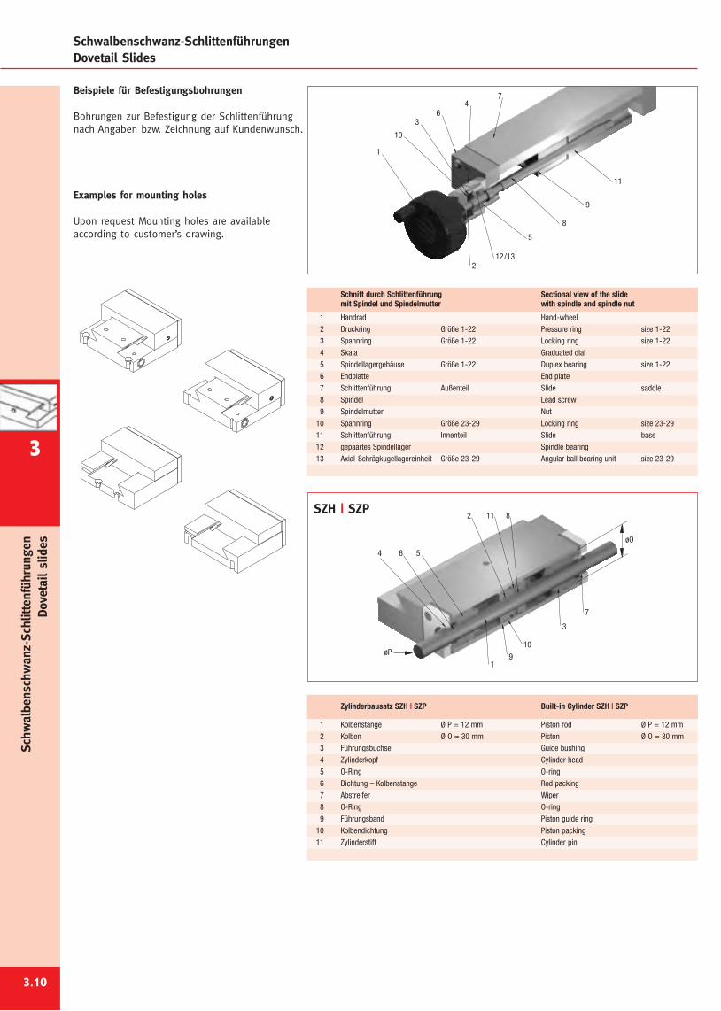
Schwalbenschwanz-SchlittenführungenDovetail Slides
Beispiele für Befestigungsbohrungen
Bohrungen zur Befestigung der Schlittenführungnach Angaben bzw. Zeichnung auf Kundenwunsch.
Examples for mounting holes
Upon request Mounting holes are availableaccording to customer’s drawing.
3.10
10
11
9
8
5
3
212/13
7
64
1
7
3
811
10
9
2
1
564
øO
øP
SZH | SZP
1 Handrad Hand-wheel2 Druckring Größe 1-22 Pressure ring size 1-223 Spannring Größe 1-22 Locking ring size 1-224 Skala Graduated dial5 Spindellagergehäuse Größe 1-22 Duplex bearing size 1-226 Endplatte End plate7 Schlittenführung Außenteil Slide saddle8 Spindel Lead screw9 Spindelmutter Nut
10 Spannring Größe 23-29 Locking ring size 23-2911 Schlittenführung Innenteil Slide base12 gepaartes Spindellager Spindle bearing13 Axial-Schrägkugellagereinheit Größe 23-29 Angular ball bearing unit size 23-29
Schnitt durch Schlittenführung Sectional view of the slidemit Spindel und Spindelmutter with spindle and spindle nut
1 Kolbenstange Ø P = 12 mm Piston rod Ø P = 12 mm2 Kolben Ø O = 30 mm Piston Ø O = 30 mm3 Führungsbuchse Guide bushing4 Zylinderkopf Cylinder head5 O-Ring O-ring6 Dichtung – Kolbenstange Rod packing7 Abstreifer Wiper8 O-Ring O-ring9 Führungsband Piston guide ring
10 Kolbendichtung Piston packing11 Zylinderstift Cylinder pin
Zylinderbausatz SZH | SZP Built-in Cylinder SZH | SZP
Schw
albenschwanz-Schlittenführungen
Dovetailslides
3
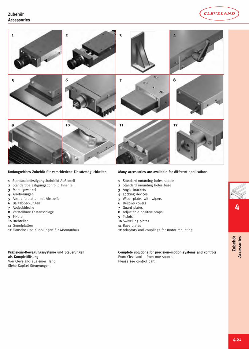
ZubehörAccessories
4.01
Umfangreiches Zubehör für verschiedene Einsatzmöglichkeiten
1 Standardbefestigungsbohrbild Außenteil2 Standardbefestigungsbohrbild Innenteil3 Montagewinkel4 Arretierungen5 Abstreiferplatten mit Abstreifer6 Balgabdeckungen7 Abdeckbleche8 Verstellbare Festanschläge9 T-Nuten10 Drehteller11 Grundplatten12 Flansche und Kupplungen für Motoranbau
Präzisions-Bewegungssysteme und Steuerungenals KomplettlösungVon Cleveland aus einer Hand.Siehe Kapitel Steuerungen.
Many accessories are available for different applications
1 Standard mounting holes saddle2 Standard mounting holes base3 Angle brackets4 Locking devices5 Wiper plates with wipers6 Bellows covers7 Guard plates8 Adjustable positive stops9 T-slots10 Swivelling plates11 Base plates12 Adaptors and couplings for motor mounting
Complete solutions for precision–motion systems and controlsFrom Cleveland – from one source.Please see control part.
4
Zubehör
Accessories
1
5
9
2
6
10
3
7
11
4
8
12
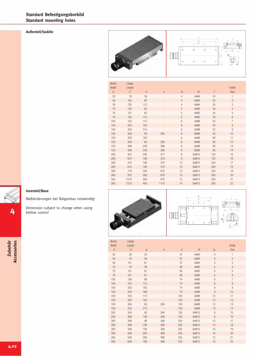
4.02
Standard BefestigungsborbildStandard mounting holes
Breite Länge
Width Lenght Größe
A C b e to d1 f Size
50 76 36 - 4 4xM4 24 1
50 102 62 - 4 4xM4 24 2
50 152 112 - 4 4xM4 24 3
75 102 62 - 5 4xM5 34 4
75 127 87 - 5 4xM5 34 5
75 152 112 - 5 4xM5 34 6
100 152 112 - 6 4xM6 52 7
100 203 163 - 6 4xM6 52 8
100 254 214 - 6 4xM6 52 9
100 305 90 265 6 8xM6 52 10
150 203 163 - 6 4xM8 95 11
150 305 90 265 6 8xM8 95 12
150 406 240 366 6 8xM8 95 13
150 406 240 366 6 8xM8 95 14
200 457 240 417 8 8xM10 120 15
200 610 190 570 8 8xM10 120 16
300 410 190 370 15 8xM10 200 17
300 610 190 570 15 8xM12 200 18
300 710 290 670 15 8xM12 200 19
300 910 290 870 15 8xM12 200 20
300 1010 490 970 15 8xM12 200 21
300 1210 490 1170 15 8xM12 200 22
Breite Länge
Width Lenght Größe
A D g h d d1 tu Size
50 50 20 - 37 4xM4 4 1
50 76 36 - 37 4xM4 4 2
50 101 61 - 37 4xM4 4 3
75 76 36 - 56 4xM5 5 4
75 101 61 - 56 4xM5 5 5
75 101 61 - 56 4xM5 5 6
100 126 86 - 74 4xM6 8 7
100 152 112 - 74 4xM6 8 8
100 203 163 - 74 4xM6 8 9
100 228 188 - 74 4xM6 8 10
150 152 112 - 120 4xM8 12 11
150 203 163 - 120 4xM8 12 12
150 304 90 264 120 8xM8 12 13
150 253 213 - 120 4xM8 12 14
200 304 90 264 155 8xM10 8 15
200 406 190 366 155 8xM10 8 16
300 308 90 268 255 8xM12 15 17
300 408 190 368 255 8xM12 15 18
300 408 190 368 255 8xM12 15 19
300 508 290 468 255 8xM12 15 20
300 508 290 468 255 8xM12 15 21
300 608 190 568 255 8xM12 15 22
beC
A
to
d1
B (1 : 1)
f
d
Zubehör
Accessories
D
gh
tud1
A (1 : 1)
f
d
Außenteil/Saddle
Innenteil/Base
Maßänderungen bei Balganbau notwendig!
Dimension subject to change when usingbellow covers!4
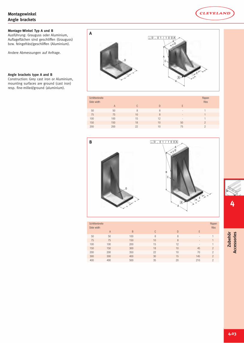
4.03
4
Zubehör
Accessories
D
=
=
=
=
E
D
C
A
B
A
A
A001/10,0
D
=
=
A
A001/10,0
=
E
D
C
A
A
A
=
MontagewinkelAngle brackets
Montage-Winkel Typ A und BAusführung: Grauguss oder Aluminium,Auflageflächen sind geschliffen (Grauguss)bzw. feingefräst/geschliffen (Aluminium).
Andere Abmessungen auf Anfrage.
Angle brackets type A and BConstruction: Grey cast iron or Aluminium,mounting surfaces are ground (cast iron)resp. fine-milled/ground (aluminium).
Schlittenbreite Rippen
Slide width Ribs
A C D E
50 50 8 8 - 1
75 75 10 8 - 1
100 100 15 12 - 1
150 150 18 10 50 2
200 200 22 10 75 2
Schlittenbreite Rippen
Slide width Ribs
A B C D E
50 50 100 8 8 - 1
75 75 150 10 8 - 1
100 100 200 15 12 - 1
150 150 300 18 10 45 2
200 200 350 22 10 70 2
300 300 400 30 15 145 2
400 400 500 35 20 210 2
A
B
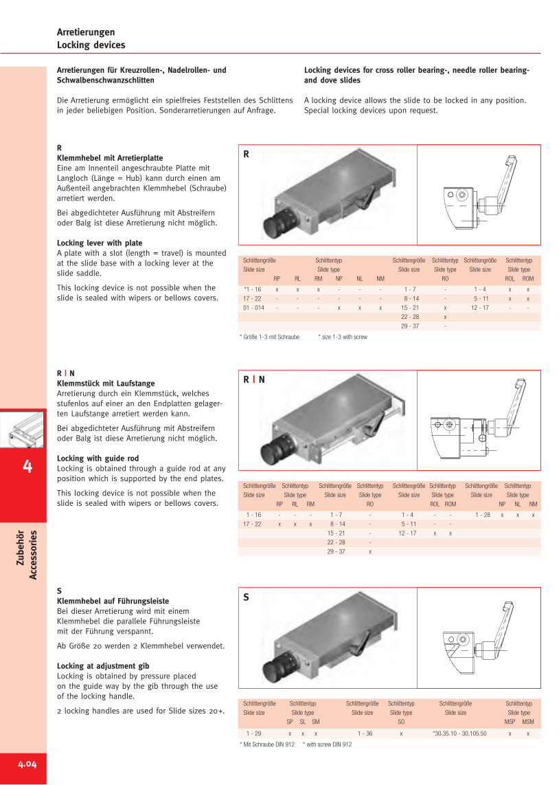
4.04
Zubehör
Accessories
*1 - 16 x x x - - - 1 - 7 - 1 - 4 x x
17 - 22 - - - - - - 8 - 14 - 5 - 11 x x
01 - 014 - - - x x x 15 - 21 x 12 - 17 - -
22 - 28 x
29 - 37 -
* Größe 1-3 mit Schraube * size 1-3 with screw
Schlittengröße Schlittentyp Schlittengröße Schlittentyp Schlittengröße Schlittentyp
Slide size Slide type Slide size Slide type Slide size Slide type
RP RL RM NP NL NM RO ROL ROM
1 - 29 x x x 1 - 36 x *30.35.10 - 30.105.50 x x
* Mit Schraube DIN 912 * with screw DIN 912
Schlittengröße Schlittentyp Schlittengröße Schlittentyp Schlittengröße Schlittentyp
Slide size Slide type Slide size Slide type Slide size Slide type
SP SL SM SO MSP MSM
1 - 16 - - - 1 - 7 - 1 - 4 - - 1 - 28 x x x
17 - 22 x x x 8 - 14 - 5 - 11 - -
15 - 21 - 12 - 17 x x
22 - 28 -
29 - 37 x
Schlittengröße Schlittentyp Schlittengröße Schlittentyp Schlittengröße Schlittentyp Schlittengröße Schlittentyp
Slide size Slide type Slide size Slide type Slide size Slide type Slide size Slide type
RP RL RM RO ROL ROM NP NL NM
ArretierungenLocking devices
RKlemmhebel mit ArretierplatteEine am Innenteil angeschraubte Platte mitLangloch (Länge = Hub) kann durch einen amAußenteil angebrachten Klemmhebel (Schraube)arretiert werden.
Bei abgedichteter Ausführung mit Abstreifernoder Balg ist diese Arretierung nicht möglich.
Locking lever with plateA plate with a slot (length = travel) is mountedat the slide base with a locking lever at theslide saddle.
This locking device is not possible when theslide is sealed with wipers or bellows covers.
R | NKlemmstück mit LaufstangeArretierung durch ein Klemmstück, welchesstufenlos auf einer an den Endplatten gelager-ten Laufstange arretiert werden kann.
Bei abgedichteter Ausführung mit Abstreifernoder Balg ist diese Arretierung nicht möglich.
Locking with guide rodLocking is obtained through a guide rod at anyposition which is supported by the end plates.
This locking device is not possible when theslide is sealed with wipers or bellows covers.
SKlemmhebel auf FührungsleisteBei dieser Arretierung wird mit einemKlemmhebel die parallele Führungsleistemit der Führung verspannt.
Ab Größe 20 werden 2 Klemmhebel verwendet.
Locking at adjustment gibLocking is obtained by pressure placedon the guide way by the gib through the useof the locking handle.
2 locking handles are used for Slide sizes 20+.
Arretierungen für Kreuzrollen-, Nadelrollen- undSchwalbenschwanzschlitten
Die Arretierung ermöglicht ein spielfreies Feststellen des Schlittensin jeder beliebigen Position. Sonderarretierungen auf Anfrage.
Locking devices for cross roller bearing-, needle roller bearing-and dove slides
A locking device allows the slide to be locked in any position.Special locking devices upon request.
R
R | N
S
4
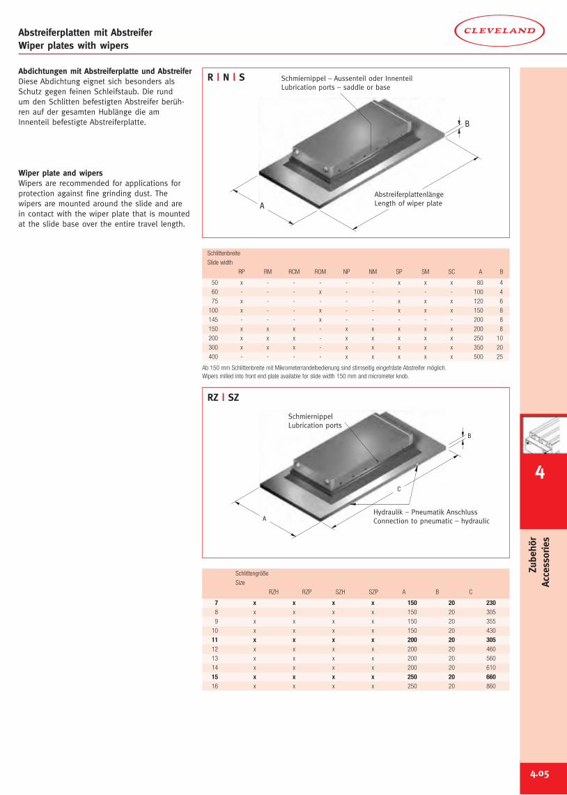
4.05
Abstreiferplatten mit AbstreiferWiper plates with wipers
Abdichtungen mit Abstreiferplatte und AbstreiferDiese Abdichtung eignet sich besonders alsSchutz gegen feinen Schleifstaub. Die rundum den Schlitten befestigten Abstreifer berüh-ren auf der gesamten Hublänge die amInnenteil befestigte Abstreiferplatte.
Wiper plate and wipersWipers are recommended for applications forprotection against fine grinding dust. Thewipers are mounted around the slide and arein contact with the wiper plate that is mountedat the slide base over the entire travel length.
Schmiernippel – Aussenteil oder InnenteilLubrication ports – saddle or base
B
AAbstreiferplattenlängeLength of wiper plate
Hydraulik – Pneumatik AnschlussConnection to pneumatic – hydraulic
B
A
C
SchmiernippelLubrication ports
50 x - - - - - x x x 80 4
60 - - - x - - - - - 100 4
75 x - - - - - x x x 120 6
100 x - - x - - x x x 150 8
145 - - - x - - - - - 200 8
150 x x x - x x x x x 200 8
200 x x x - x x x x x 250 10
300 x x x - x x x x x 350 20
400 - - - - x x x x x 500 25
Ab 150 mm Schlittenbreite mit Mikrometerrandelbedienung sind stirnseitig eingefräste Abstreifer möglich.Wipers milled into front end plate available for slide width 150 mm and micrometer knob.
Schlittenbreite
Slide width
RP RM RCM ROM NP NM SP SM SC A B
7 x x x x 150 20 2308 x x x x 150 20 305
9 x x x x 150 20 355
10 x x x x 150 20 430
11 x x x x 200 20 30512 x x x x 200 20 460
13 x x x x 200 20 560
14 x x x x 200 20 610
15 x x x x 250 20 66016 x x x x 250 20 860
Schlittengröße
Size
RZH RZP SZH SZP A B C
R | N | S
RZ | SZ
4
Zubehör
Accessories
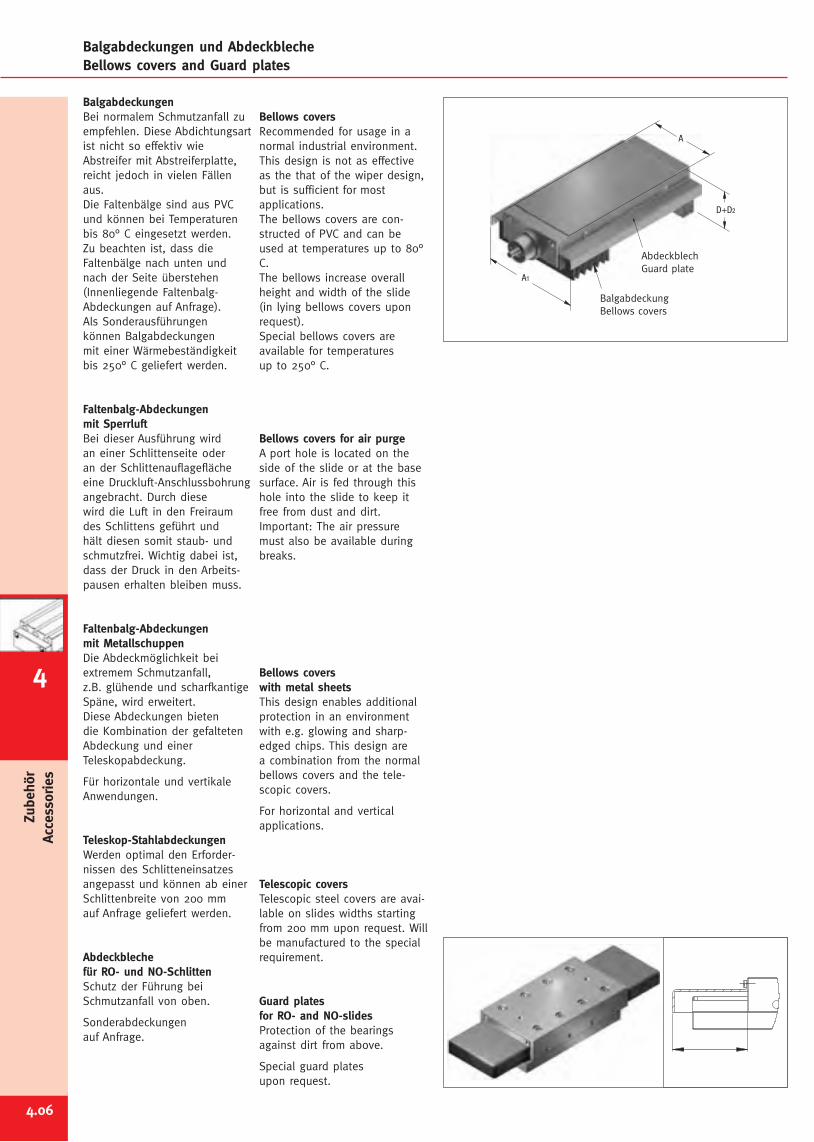
4.06
Zubehör
Accessories
Balgabdeckungen und AbdeckblecheBellows covers and Guard plates
BalgabdeckungenBei normalem Schmutzanfall zuempfehlen. Diese Abdichtungsartist nicht so effektiv wieAbstreifer mit Abstreiferplatte,reicht jedoch in vielen Fällenaus.Die Faltenbälge sind aus PVCund können bei Temperaturenbis 80° C eingesetzt werden.Zu beachten ist, dass dieFaltenbälge nach unten undnach der Seite überstehen(Innenliegende Faltenbalg-Abdeckungen auf Anfrage).Als Sonderausführungenkönnen Balgabdeckungenmit einer Wärmebeständigkeitbis 250° C geliefert werden.
Faltenbalg-Abdeckungenmit SperrluftBei dieser Ausführung wirdan einer Schlittenseite oderan der Schlittenauflageflächeeine Druckluft-Anschlussbohrungangebracht. Durch diesewird die Luft in den Freiraumdes Schlittens geführt undhält diesen somit staub- undschmutzfrei. Wichtig dabei ist,dass der Druck in den Arbeits-pausen erhalten bleiben muss.
Faltenbalg-Abdeckungenmit MetallschuppenDie Abdeckmöglichkeit beiextremem Schmutzanfall,z.B. glühende und scharfkantigeSpäne, wird erweitert.Diese Abdeckungen bietendie Kombination der gefaltetenAbdeckung und einerTeleskopabdeckung.
Für horizontale und vertikaleAnwendungen.
Teleskop-StahlabdeckungenWerden optimal den Erforder-nissen des Schlitteneinsatzesangepasst und können ab einerSchlittenbreite von 200 mmauf Anfrage geliefert werden.
Abdeckblechefür RO- und NO-SchlittenSchutz der Führung beiSchmutzanfall von oben.
Sonderabdeckungenauf Anfrage.
Bellows coversRecommended for usage in anormal industrial environment.This design is not as effectiveas the that of the wiper design,but is sufficient for mostapplications.The bellows covers are con-structed of PVC and can beused at temperatures up to 80°C.The bellows increase overallheight and width of the slide(in lying bellows covers uponrequest).Special bellows covers areavailable for temperaturesup to 250° C.
Bellows covers for air purgeA port hole is located on theside of the slide or at the basesurface. Air is fed through thishole into the slide to keep itfree from dust and dirt.Important: The air pressuremust also be available duringbreaks.
Bellows coverswith metal sheetsThis design enables additionalprotection in an environmentwith e.g. glowing and sharp-edged chips. This design area combination from the normalbellows covers and the tele-scopic covers.
For horizontal and verticalapplications.
Telescopic coversTelescopic steel covers are avai-lable on slides widths startingfrom 200 mm upon request. Willbe manufactured to the specialrequirement.
Guard platesfor RO- and NO-slidesProtection of the bearingsagainst dirt from above.
Special guard platesupon request.
AbdeckblechGuard plate
BalgabdeckungBellows covers
A1
D+D2
A
4
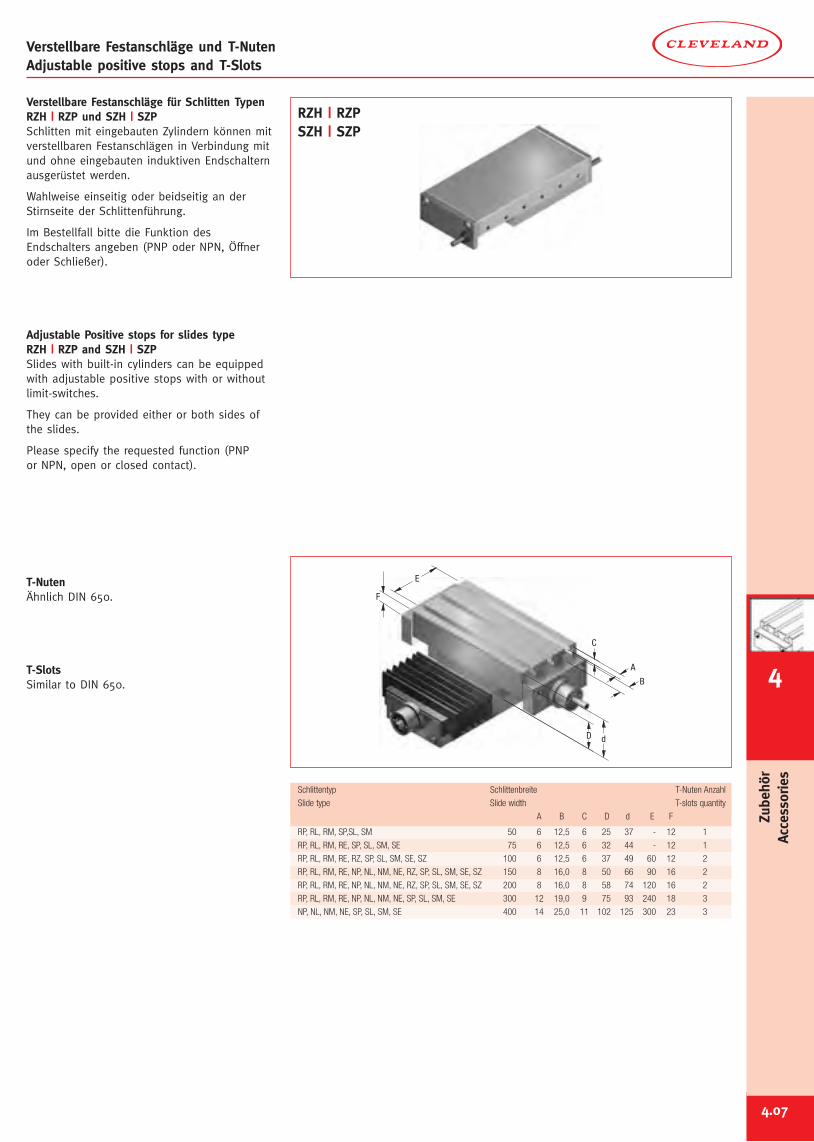
4.07
Verstellbare Festanschläge für Schlitten TypenRZH | RZP und SZH | SZPSchlitten mit eingebauten Zylindern können mitverstellbaren Festanschlägen in Verbindung mitund ohne eingebauten induktiven Endschalternausgerüstet werden.
Wahlweise einseitig oder beidseitig an derStirnseite der Schlittenführung.
Im Bestellfall bitte die Funktion desEndschalters angeben (PNP oder NPN, Öffneroder Schließer).
Adjustable Positive stops for slides typeRZH | RZP and SZH | SZPSlides with built-in cylinders can be equippedwith adjustable positive stops with or withoutlimit-switches.
They can be provided either or both sides ofthe slides.
Please specify the requested function (PNPor NPN, open or closed contact).
T-NutenÄhnlich DIN 650.
T-SlotsSimilar to DIN 650.
Verstellbare Festanschläge und T-NutenAdjustable positive stops and T-Slots
C
F
d
E
D
A
B
RP, RL, RM, SP,SL, SM 50 6 12,5 6 25 37 - 12 1
RP, RL, RM, RE, SP, SL, SM, SE 75 6 12,5 6 32 44 - 12 1
RP, RL, RM, RE, RZ, SP, SL, SM, SE, SZ 100 6 12,5 6 37 49 60 12 2
RP, RL, RM, RE, NP, NL, NM, NE, RZ, SP, SL, SM, SE, SZ 150 8 16,0 8 50 66 90 16 2
RP, RL, RM, RE, NP, NL, NM, NE, RZ, SP, SL, SM, SE, SZ 200 8 16,0 8 58 74 120 16 2
RP, RL, RM, RE, NP, NL, NM, NE, SP, SL, SM, SE 300 12 19,0 9 75 93 240 18 3
NP, NL, NM, NE, SP, SL, SM, SE 400 14 25,0 11 102 125 300 23 3
Schlittentyp Schlittenbreite T-Nuten Anzahl
Slide type Slide width T-slots quantity
A B C D d E F
RZH | RZPSZH | SZP
4
Zubehör
Accessories
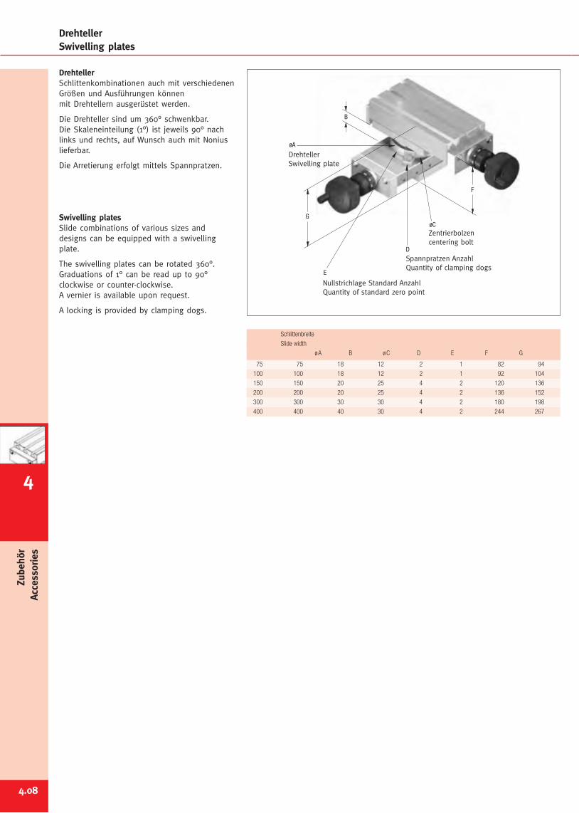
4.08
Zubehör
Accessories
DrehtellerSchlittenkombinationen auch mit verschiedenenGrößen und Ausführungen könnenmit Drehtellern ausgerüstet werden.
Die Drehteller sind um 360° schwenkbar.Die Skaleneinteilung (1°) ist jeweils 90° nachlinks und rechts, auf Wunsch auch mit Noniuslieferbar.
Die Arretierung erfolgt mittels Spannpratzen.
Swivelling platesSlide combinations of various sizes anddesigns can be equipped with a swivellingplate.
The swivelling plates can be rotated 360°.Graduations of 1° can be read up to 90°clockwise or counter-clockwise.A vernier is available upon request.
A locking is provided by clamping dogs.
DrehtellerSwivelling plates
Nullstrichlage Standard AnzahlQuantity of standard zero point
Spannpratzen AnzahlQuantity of clamping dogs
DrehtellerSwivelling plate
Zentrierbolzencentering bolt
B
G
F
øC
øA
E
D
75 75 18 12 2 1 82 94
100 100 18 12 2 1 92 104
150 150 20 25 4 2 120 136
200 200 20 25 4 2 136 152
300 300 30 30 4 2 180 198
400 400 40 30 4 2 244 267
Schlittenbreite
Slide width
øA B øC D E F G
4
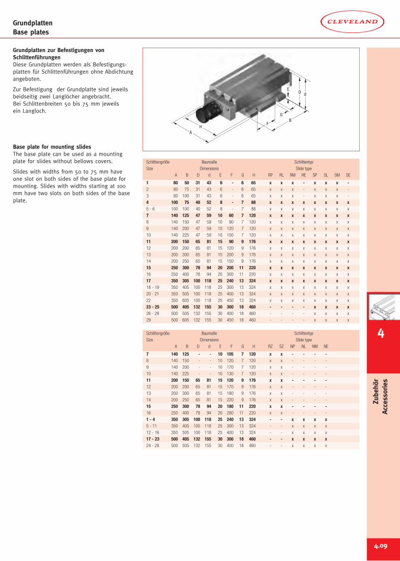
4.09
GrundplattenBase plates
Grundplatten zur Befestigungen vonSchlittenführungenDiese Grundplatten werden als Befestigungs-platten für Schlittenführungen ohne Abdichtungangeboten.
Zur Befestigung der Grundplatte sind jeweilsbeidseitig zwei Langlöcher angebracht.Bei Schlittenbreiten 50 bis 75 mm jeweilsein Langloch.
Base plate for mounting slidesThe base plate can be used as a mountingplate for slides without bellows covers.
Slides with widths from 50 to 75 mm haveone slot on both sides of the base plate formounting. Slides with widths starting at 100mm have two slots on both sides of the baseplate.
G
FB
dE
HA
D
1 80 50 31 43 6 - 6 65 x x x - x x x -2 80 75 31 43 6 - 6 65 x x x - x x x -
3 80 100 31 43 6 - 6 65 x x x - x x x -
4 100 75 40 52 8 - 7 88 x x x x x x x x5 - 6 100 100 40 52 8 - 7 88 x x x x x x x x
7 140 125 47 59 10 60 7 120 x x x x x x x x8 140 150 47 59 10 90 7 120 x x x x x x x x
9 140 200 47 59 10 120 7 120 x x x x x x x x
10 140 225 47 59 10 150 7 120 x x x x x x x x
11 200 150 65 81 15 90 9 176 x x x x x x x x12 200 200 65 81 15 120 9 176 x x x x x x x x
13 200 300 65 81 15 200 9 176 x x x x x x x x
14 200 250 65 81 15 150 9 176 x x x x x x x x
15 250 300 78 94 20 200 11 220 x x x x x x x x16 250 400 78 94 20 300 11 220 x x x x x x x x
17 350 305 100 118 25 240 13 324 x x x x x x x x18 - 19 350 405 100 118 25 300 13 324 x x x x x x x x
20 - 21 350 505 100 118 25 400 13 324 x x x x x x x x
22 350 605 100 118 25 450 13 324 x x x x x x x x
23 - 25 500 405 132 155 30 300 18 460 - - - - x x x x26 - 28 500 505 132 155 30 400 18 460 - - - - x x x x
29 500 605 132 155 30 450 18 460 - - - - x x x x
Schlittengröße Baumaße Schlittentyp
Size Dimensions Slide type
A B D d E F G H RP RL RM RE SP SL SM SE
7 140 125 - - 10 105 7 120 x x - - - -8 140 150 - - 10 120 7 120 x x - - - -
9 140 200 - - 10 170 7 120 x x - - - -
10 140 225 - - 10 130 7 120 x x - - - -
11 200 150 65 81 15 120 9 176 x x - - - -12 200 200 65 81 15 170 9 176 x x - - - -
13 200 300 65 81 15 180 9 176 x x - - - -
14 200 250 65 81 15 220 9 176 x x - - - -
15 250 300 78 94 20 180 11 220 x x - - - -16 250 400 78 94 20 280 11 220 x x - - - -
1 - 4 350 305 100 118 25 240 13 324 - - x x x x5 - 11 350 405 100 118 25 300 13 324 - - x x x x
12 - 16 350 505 100 118 25 400 13 324 - - x x x x
17 - 23 500 405 132 155 30 300 18 460 - - x x x x24 - 28 500 505 132 155 30 400 18 460 - - x x x x
Schlittengröße Baumaße Schlittentyp
Size Dimensions Slide type
A B D d E F G H RZ SZ NP NL NM NE
4
Zubehör
Accessories
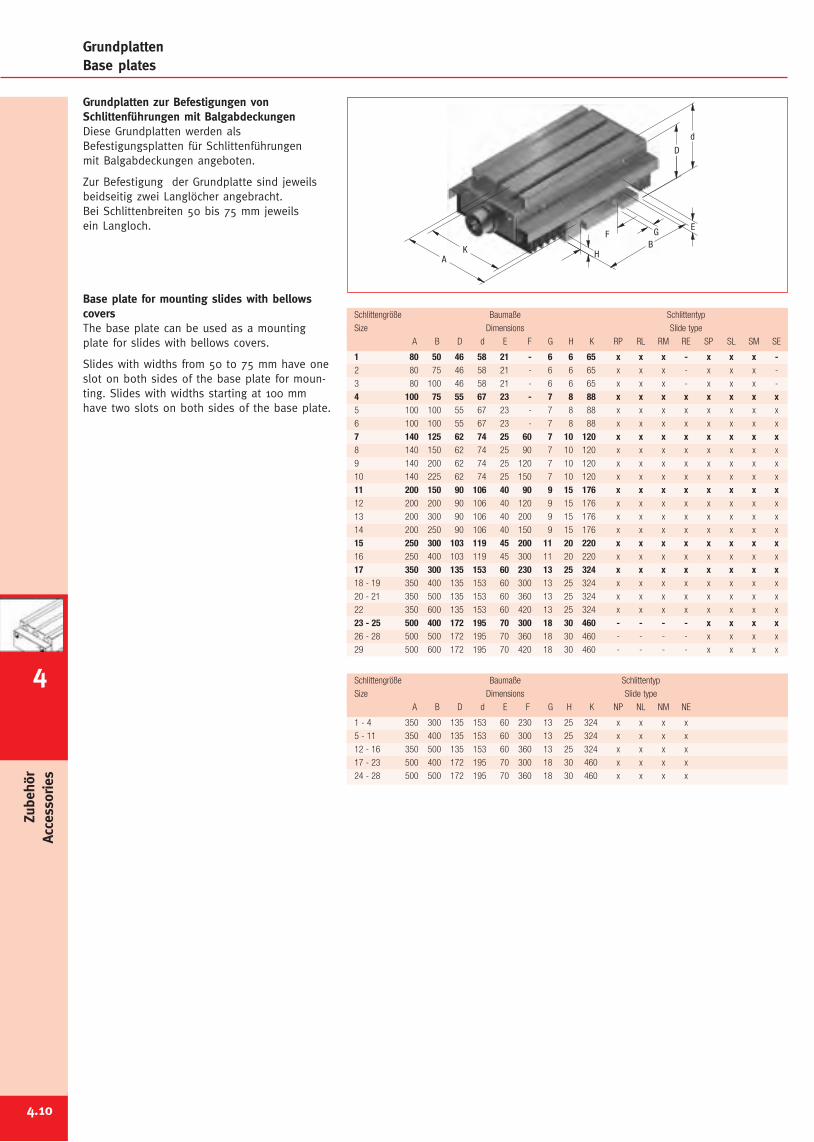
4.10
Zubehör
Accessories
GrundplattenBase plates
Grundplatten zur Befestigungen vonSchlittenführungen mit BalgabdeckungenDiese Grundplatten werden alsBefestigungsplatten für Schlittenführungenmit Balgabdeckungen angeboten.
Zur Befestigung der Grundplatte sind jeweilsbeidseitig zwei Langlöcher angebracht.Bei Schlittenbreiten 50 bis 75 mm jeweilsein Langloch.
Base plate for mounting slides with bellowscoversThe base plate can be used as a mountingplate for slides with bellows covers.
Slides with widths from 50 to 75 mm have oneslot on both sides of the base plate for moun-ting. Slides with widths starting at 100 mmhave two slots on both sides of the base plate.
E
d
D
H
G
AK B
F
1 80 50 46 58 21 - 6 6 65 x x x - x x x -2 80 75 46 58 21 - 6 6 65 x x x - x x x -
3 80 100 46 58 21 - 6 6 65 x x x - x x x -
4 100 75 55 67 23 - 7 8 88 x x x x x x x x5 100 100 55 67 23 - 7 8 88 x x x x x x x x
6 100 100 55 67 23 - 7 8 88 x x x x x x x x
7 140 125 62 74 25 60 7 10 120 x x x x x x x x8 140 150 62 74 25 90 7 10 120 x x x x x x x x
9 140 200 62 74 25 120 7 10 120 x x x x x x x x
10 140 225 62 74 25 150 7 10 120 x x x x x x x x
11 200 150 90 106 40 90 9 15 176 x x x x x x x x12 200 200 90 106 40 120 9 15 176 x x x x x x x x
13 200 300 90 106 40 200 9 15 176 x x x x x x x x
14 200 250 90 106 40 150 9 15 176 x x x x x x x x
15 250 300 103 119 45 200 11 20 220 x x x x x x x x16 250 400 103 119 45 300 11 20 220 x x x x x x x x
17 350 300 135 153 60 230 13 25 324 x x x x x x x x18 - 19 350 400 135 153 60 300 13 25 324 x x x x x x x x
20 - 21 350 500 135 153 60 360 13 25 324 x x x x x x x x
22 350 600 135 153 60 420 13 25 324 x x x x x x x x
23 - 25 500 400 172 195 70 300 18 30 460 - - - - x x x x26 - 28 500 500 172 195 70 360 18 30 460 - - - - x x x x
29 500 600 172 195 70 420 18 30 460 - - - - x x x x
Schlittengröße Baumaße Schlittentyp
Size Dimensions Slide type
A B D d E F G H K RP RL RM RE SP SL SM SE
1 - 4 350 300 135 153 60 230 13 25 324 x x x x
5 - 11 350 400 135 153 60 300 13 25 324 x x x x
12 - 16 350 500 135 153 60 360 13 25 324 x x x x
17 - 23 500 400 172 195 70 300 18 30 460 x x x x
24 - 28 500 500 172 195 70 360 18 30 460 x x x x
Schlittengröße Baumaße Schlittentyp
Size Dimensions Slide type
A B D d E F G H K NP NL NM NE
4
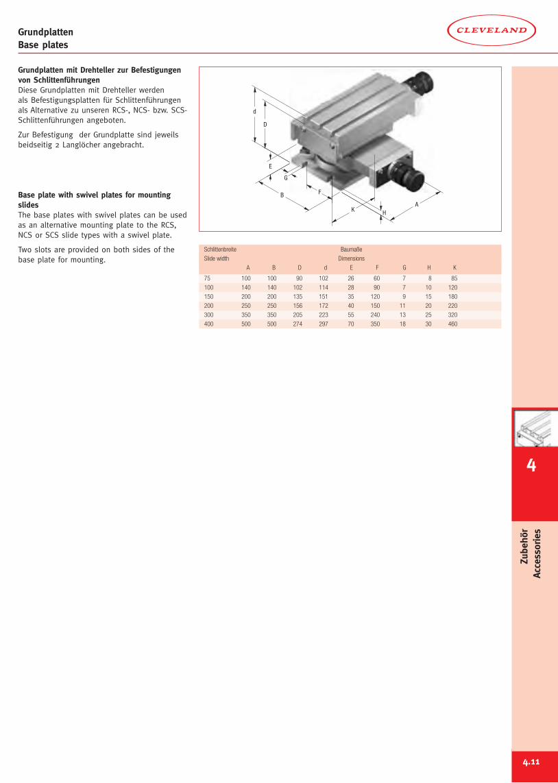
4.11
GrundplattenBase plates
HA
K
G
B F
E
D
d
75 100 100 90 102 26 60 7 8 85
100 140 140 102 114 28 90 7 10 120
150 200 200 135 151 35 120 9 15 180
200 250 250 156 172 40 150 11 20 220
300 350 350 205 223 55 240 13 25 320
400 500 500 274 297 70 350 18 30 460
Schlittenbreite Baumaße
Slide width Dimensions
A B D d E F G H K
Grundplatten mit Drehteller zur Befestigungenvon SchlittenführungenDiese Grundplatten mit Drehteller werdenals Befestigungsplatten für Schlittenführungenals Alternative zu unseren RCS-, NCS- bzw. SCS-Schlittenführungen angeboten.
Zur Befestigung der Grundplatte sind jeweilsbeidseitig 2 Langlöcher angebracht.
Base plate with swivel plates for mountingslidesThe base plates with swivel plates can be usedas an alternative mounting plate to the RCS,NCS or SCS slide types with a swivel plate.
Two slots are provided on both sides of thebase plate for mounting.
4
Zubehör
Accessories
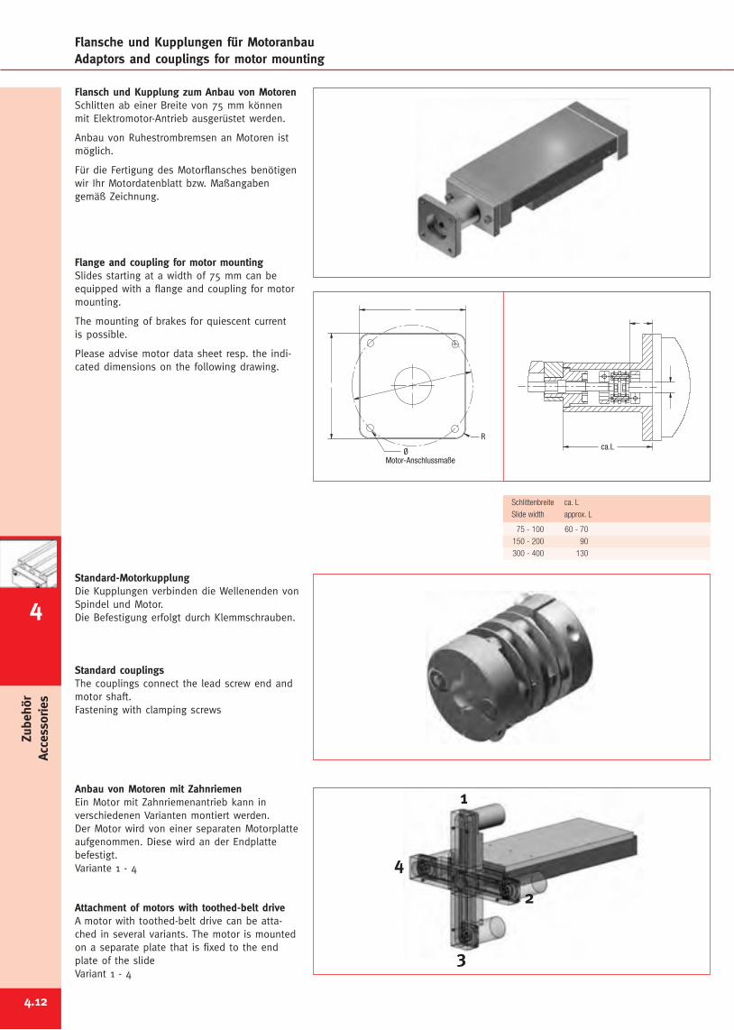
4.12
Zubehör
Accessories
Flansche und Kupplungen für MotoranbauAdaptors and couplings for motor mounting
Flansch und Kupplung zum Anbau von MotorenSchlitten ab einer Breite von 75 mm könnenmit Elektromotor-Antrieb ausgerüstet werden.
Anbau von Ruhestrombremsen an Motoren istmöglich.
Für die Fertigung des Motorflansches benötigenwir Ihr Motordatenblatt bzw. Maßangabengemäß Zeichnung.
Flange and coupling for motor mountingSlides starting at a width of 75 mm can beequipped with a flange and coupling for motormounting.
The mounting of brakes for quiescent currentis possible.
Please advise motor data sheet resp. the indi-cated dimensions on the following drawing.
Standard-MotorkupplungDie Kupplungen verbinden die Wellenenden vonSpindel und Motor.Die Befestigung erfolgt durch Klemmschrauben.
Standard couplingsThe couplings connect the lead screw end andmotor shaft.Fastening with clamping screws
Anbau von Motoren mit ZahnriemenEin Motor mit Zahnriemenantrieb kann inverschiedenen Varianten montiert werden.Der Motor wird von einer separaten Motorplatteaufgenommen. Diese wird an der Endplattebefestigt.Variante 1 - 4
Attachment of motors with toothed-belt driveA motor with toothed-belt drive can be atta-ched in several variants. The motor is mountedon a separate plate that is fixed to the endplate of the slideVariant 1 - 4
Motor-Anschlussmaße
R
Øca.L
Schlittenbreite ca. L
Slide width approx. L
75 - 100 60 - 70
150 - 200 90
300 - 400 130
1
2
3
4
4
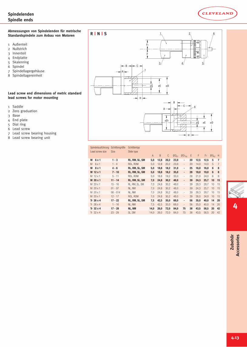
SpindelendenSpindle ends
4.13
Abmessungen von Spindelenden für metrischeStandardspindeln zum Anbau von Motoren
1 Außenteil2 Nullstrich3 Innenteil4 Endplatte5 Skalenring6 Spindel7 Spindellagergehäuse8 Spindellagereinheit
Lead screw end dimensions of metric standardlead screws for motor mounting
1 Saddle2 Zero graduation3 Base4 End plate5 Dial ring6 Lead screw7 Lead screw bearing housing8 Lead screw bearing unit
621
F
F1
543
M 6 x 1 1 - 3 RL, RM, SL, SM 5,0 12,8 20,2 23,9 - 20 12,5 12,5 5 7M 6 x 1 1 - 4 ROL, ROM 5,0 12,8 20,2 23,9 - 20 14,0 14,0 5 7
M 8 x 1 4 - 6 RL, RM, SL, SM 5,0 18,8 18,2 31,0 - 25 16,0 16,0 6 8M 12 x 1 7 - 10 RL, RM, SL, SM 5,0 18,8 18,2 35,0 - 28 18,0 19,0 6 8M 12 x 1 5 - 11 ROL, ROM 5,0 18,8 18,2 35,0 - 28 21,0 24,0 6 8
M 20 x 1 11 - 14 RL, RM, SL, SM 7,0 24,8 30,2 48,0 - 39 24,3 25,7 10 15M 20 x 1 15 - 16 RL, RM, SL, SM 7,0 24,8 30,2 48,0 - 39 28,3 29,7 10 15
M 20 x 1 01 - 07 NL, NM 7,0 24,8 30,2 48,0 - 39 24,3 25,7 10 15
M 20 x 1 08 - 014 NL, NM 7,0 24,8 30,2 48,0 - 39 28,3 29,7 10 15
M 20 x 1 12 - 17 ROL, ROM 7,0 24,8 30,2 48,0 - 39 26,0 34,0 10 15
Tr 26 x 4 17 - 22 RL, RM, SL, SM 7,5 42,5 35,0 68,0 - 56 35,0 40,0 14 20Tr 26 x 4 1 - 16 NL, NM 7,5 42,5 35,0 68,0 - 56 35,0 40,0 14 20
Tr 32 x 4 17 - 28 NL, NM 14,0 26,0 72,0 84,0 75 38 43,5 58,5 20 42Tr 32 x 4 23 - 29 SL, SM 14,0 26,0 72,0 84,0 75 38 43,5 58,5 20 42
Spindelausführung Schlittengröße Schlittentyp
Lead screw size Size Slide type
A B C ØDh7 ØD1h5 E F F1 ØGh7 H
7
H
ØDØEØG
CB
A
8
ØD1ØDØE
CB
A
H
ØG
R | N | S
4
Zubehör
Accessories
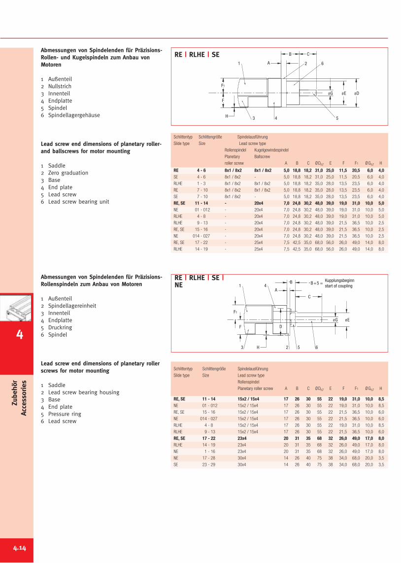
Zubehör
Accessories
Abmessungen von Spindelenden für Präzisions-Rollen- und Kugelspindeln zum Anbau vonMotoren
1 Außenteil2 Nullstrich3 Innenteil4 Endplatte5 Spindel6 Spindellagergehäuse
Lead screw end dimensions of planetary roller-and ballscrews for motor mounting
1 Saddle2 Zero graduation3 Base4 End plate5 Lead screw6 Lead screw bearing unit
Abmessungen von Spindelenden für Präzisions-Rollenspindeln zum Anbau von Motoren
1 Außenteil2 Spindellagereinheit3 Innenteil4 Endplatte5 Druckring6 Spindel
Lead screw end dimensions of planetary rollerscrews for motor mounting
1 Saddle2 Lead screw bearing housing3 Base4 End plate5 Pressure ring6 Lead screw
2
3
1
4 5
6
H
F
F1
ØDØEØG
CB
A
ØE
* B+5 =
652
4
3
1
H
F
F1
D
ØG
C
*B
A
Kupplungsbeginnstart of coupling
RE 4 - 6 8x1 / 8x2 8x1 / 8x2 5,0 18,8 18,2 31,0 25,0 11,5 20,5 6,0 4,0SE 4 - 6 8x1 / 8x2 - 5,0 18,8 18,2 31,0 25,0 11,5 20,5 6,0 4,0
RLHE 1 - 3 8x1 / 8x2 8x1 / 8x2 5,0 18,8 18,2 35,0 28,0 13,5 23,5 6,0 4,0
RE 7 - 10 8x1 / 8x2 8x1 / 8x2 5,0 18,8 18,2 35,0 28,0 13,5 23,5 6,0 4,0
SE 7 - 10 8x1 / 8x2 - 5,0 18,8 18,2 35,0 28,0 13,5 23,5 6,0 4,0
RE, SE 11 - 14 - 20x4 7,0 24,8 30,2 48,0 39,0 19,0 31,0 10,0 5,0NE 01 - 012 - 20x4 7,0 24,8 30,2 48,0 39,0 19,0 31,0 10,0 5,0
RLHE 4 - 8 - 20x4 7,0 24,8 30,2 48,0 39,0 19,0 31,0 10,0 5,0
RLHE 9 - 13 - 20x4 7,0 24,8 30,2 48,0 39,0 21,5 36,5 10,0 2,5
RE, SE 15 - 16 - 20x4 7,0 24,8 30,2 48,0 39,0 21,5 36,5 10,0 2,5
NE 014 - 027 - 20x4 7,0 24,8 30,2 48,0 39,0 21,5 36,5 10,0 2,5
RE, SE 17 - 22 - 25x4 7,5 42,5 35,0 68,0 56,0 26,0 49,0 14,0 8,0
RLHE 14 - 19 - 25x4 7,5 42,5 35,0 68,0 56,0 26,0 49,0 14,0 8,0
Schlittentyp Schlittengröße Spindelausführung
Slide type Size Lead screw type
Rollenspindel Kugelgewindespindel
Planetary Ballscrew
roller screw A B C ØDh7 E F F1 ØGh7 H
RE, SE 11 - 14 15x2 / 15x4 17 26 30 55 22 19,0 31,0 10,0 8,5NE 01 - 012 15x2 / 15x4 17 26 30 55 22 19,0 31,0 10,0 8,5
RE, SE 15 - 16 15x2 / 15x4 17 26 30 55 22 21,5 36,5 10,0 6,0
NE 014 - 027 15x2 / 15x4 17 26 30 55 22 21,5 36,5 10,0 6,0
RLHE 4 - 8 15x2 / 15x4 17 26 30 55 22 19,0 31,0 10,0 8,5
RLHE 9 - 13 15x2 / 15x4 17 26 30 55 22 21,5 36,5 10,0 6,0
RE, SE 17 - 22 23x4 20 31 35 68 32 26,0 49,0 17,0 8,0RLHE 14 - 19 23x4 20 31 35 68 32 26,0 49,0 17,0 8,0
NE 1 - 16 23x4 20 31 35 68 32 26,0 49,0 17,0 8,0
NE 17 - 28 30x4 14 26 40 75 38 34,0 68,0 20,0 3,5
SE 23 - 29 30x4 14 26 40 75 38 34,0 68,0 20,0 3,5
Schlittentyp Schlittengröße Spindelausführung
Slide type Size Lead screw type
Rollenspindel
Planetary roller screw A B C ØDh7 E F F1 ØGh7 H
RE | RLHE | SE
RE | RLHE | SE |NE
4.14
4
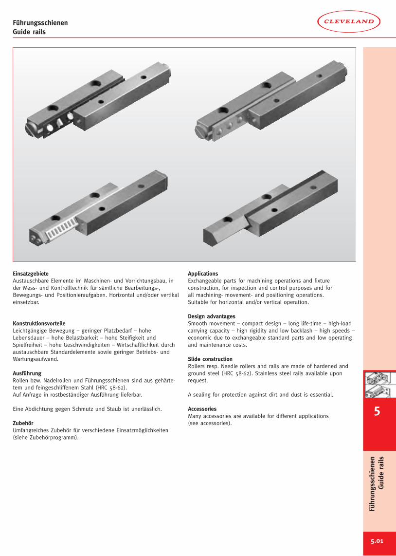
FührungsschienenGuide rails
5.01
6
Führungsschienen
Guide
rails
EinsatzgebieteAustauschbare Elemente im Maschinen- und Vorrichtungsbau, inder Mess- und Kontrolltechnik für sämtliche Bearbeitungs-,Bewegungs- und Positionieraufgaben. Horizontal und/oder vertikaleinsetzbar.
KonstruktionsvorteileLeichtgängige Bewegung – geringer Platzbedarf – hoheLebensdauer – hohe Belastbarkeit – hohe Steifigkeit undSpielfreiheit – hohe Geschwindigkeiten – Wirtschaftlichkeit durchaustauschbare Standardelemente sowie geringer Betriebs- undWartungsaufwand.
AusführungRollen bzw. Nadelrollen und Führungsschienen sind aus gehärte-tem und feingeschliffenem Stahl (HRC 58-62).Auf Anfrage in rostbeständiger Ausführung lieferbar.
Eine Abdichtung gegen Schmutz und Staub ist unerlässlich.
ZubehörUmfangreiches Zubehör für verschiedene Einsatzmöglichkeiten(siehe Zubehörprogramm).
ApplicationsExchangeable parts for machining operations and fixtureconstruction, for inspection and control purposes and forall machining- movement- and positioning operations.Suitable for horizontal and/or vertical operation.
Design advantagesSmooth movement – compact design – long life-time – high-loadcarrying capacity – high rigidity and low backlash – high speeds –economic due to exchangeable standard parts and low operatingand maintenance costs.
Slide constructionRollers resp. Needle rollers and rails are made of hardened andground steel (HRC 58-62). Stainless steel rails available uponrequest.
A sealing for protection against dirt and dust is essential.
AccessoriesMany accessories are available for different applications(see accessories).
5
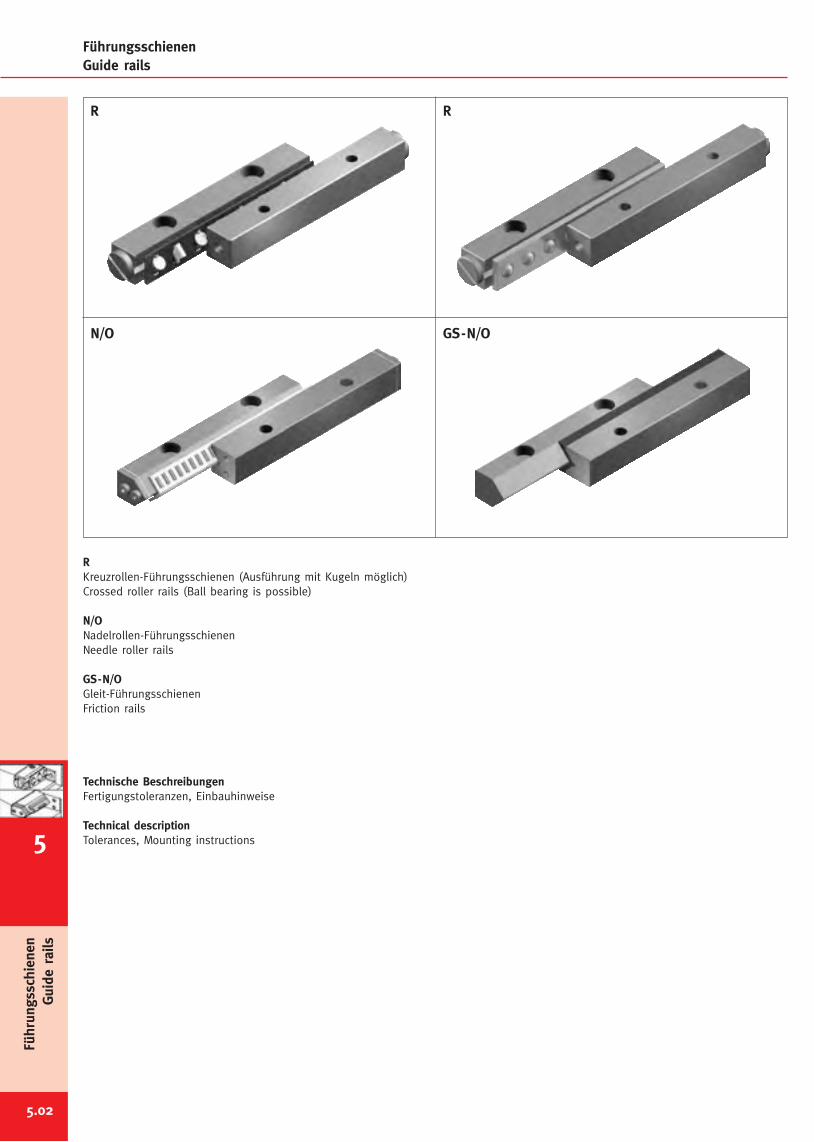
FührungsschienenGuide rails
5.02
R
N/O
R
GS-N/O
RKreuzrollen-Führungsschienen (Ausführung mit Kugeln möglich)Crossed roller rails (Ball bearing is possible)
N/ONadelrollen-FührungsschienenNeedle roller rails
GS-N/OGleit-FührungsschienenFriction rails
Technische BeschreibungenFertigungstoleranzen, Einbauhinweise
Technical descriptionTolerances, Mounting instructions
Führungsschienen
Guide
rails
5
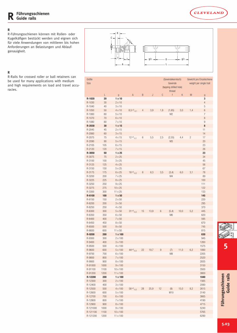
5.03
R FührungsschienenGuide rails
Größe (Gewindekernloch) Gewicht pro Einzelschiene
Size Gewinde weight per single trail
(tapping drilled hole)
thread
L g A B J C f K M gR-1020 20 1 x 10 3R-1030 30 2 x 10 4
R-1040 40 3 x 10 5
R-1050 50 4 x 10 8,5+0-0,1 4 3,9 1,8 (1,65) 3,0 1,4 6
R-1060 60 5 x 10 M2 7
R-1070 70 6 x 10 8
R-1080 80 7 x 10 9
R-2030 30 1 x 15 8R-2045 45 2 x 15 11
R-2060 60 3 x 15 14
R-2075 75 4 x 15 12+0-0,1 6 5,5 2,5 (2,55) 4,4 2 17
R-2090 90 5 x 15 M3 20
R-2105 105 6 x 15 23
R-2120 120 7 x 15 26
R-3050 50 1 x 25 23R-3075 75 2 x 25 34
R-3100 100 3 x 25 45
R-3125 125 4 x 25 56
R-3150 150 5 x 25 67
R-3175 175 6 x 25 18+0-0,2 8 8,3 3,5 (3,4) 6,0 3,1 78
R-3200 200 7 x 25 M4 89
R-3225 225 8 x 25 100
R-3250 250 9 x 25 111
R-3275 275 10 x 25 122
R-3300 300 11 x 25 133
R-6100 100 1 x 50 145R-6150 150 2 x 50 220
R-6200 200 3 x 50 295
R-6250 250 4 x 50 370
R-6300 300 5 x 50 31+0-0,3 15 13,9 6 (5,4) 10,0 5,2 445
R-6350 350 6 x 50 M6 620
R-6400 400 7 x 50 595
R-6450 450 8 x 50 670
R-6500 500 9 x 50 745
R-6600 600 11 x 50 815
R-9200 200 1 x 100 630R-9300 300 2 x 100 945
R-9400 400 3 x 100 1260
R-9500 500 4 x 100 1575
R-9600 600 5 x 100 44+0-0,3 22 19,7 9 (7) 11,0 6,2 1890
R-9700 700 6 x 100 M8 2205
R-9800 800 7 x 100 2520
R-9900 900 8 x 100 2835
R-91000 1000 9 x 100 3150
R-91100 1100 10 x 100 3500
R-91200 1200 11 x 100 3800
R-12200 200 1 x 100 1040R-12300 300 2 x 100 1565
R-12400 400 3 x 100 2090
R-12500 500 4 x 100 58+0-0,3 28 25,9 12 (9) 15,0 8,2 2615
R-12600 600 5 x 100 M10 3140
R-12700 700 6 x 100 3665
R-12800 800 7 x 100 4190
R-12900 900 8 x 100 4715
R-121000 1000 9 x 100 5240
R-121100 1100 10 x 100 5765
R-121200 1200 11 x 100 6290
RR-Führungsschienen können mit Rollen- oderKugelkäfigen bestückt werden und eignen sichfür viele Anwendungen von mittleren bis hohenAnforderungen an Belastungen und Ablauf-genauigkeit.
RR-Rails for crossed roller or ball retainers canbe used for many applications with mediumand high requirements on load and travel accu-racies.
L
g/2gg/2
A
D
J
BM
K
C
f
6
Führungsschienen
Guide
rails
5
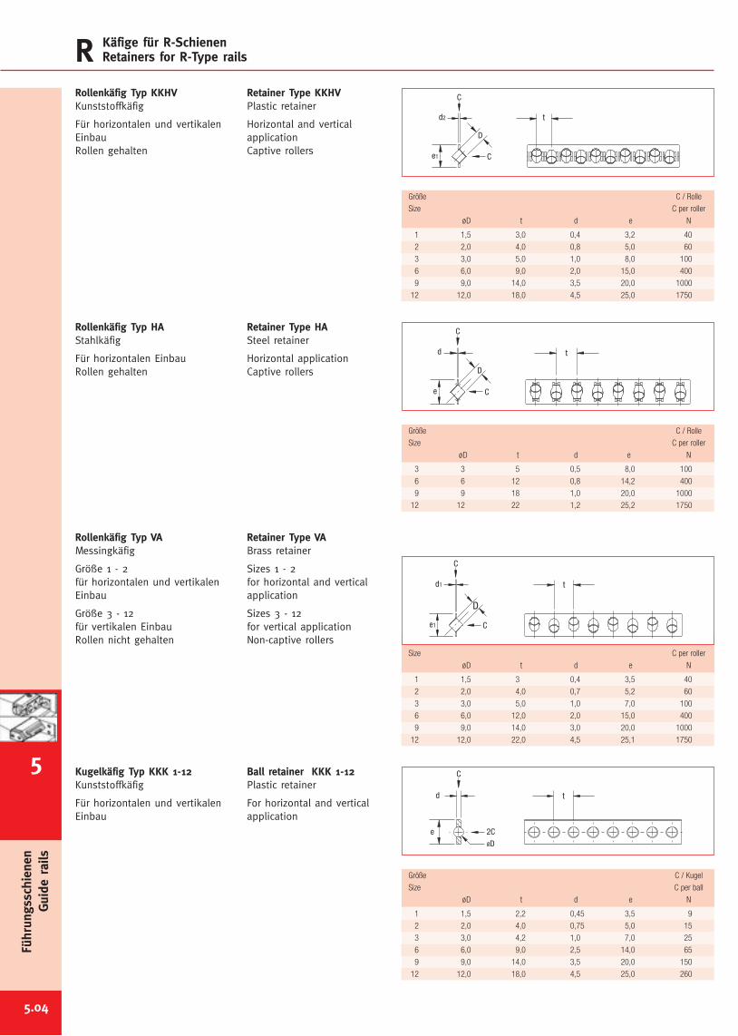
Größe C / Kugel
Size C per ball
øD t d e N
1 1,5 2,2 0,45 3,5 9
2 2,0 4,0 0,75 5,0 15
3 3,0 4,2 1,0 7,0 25
6 6,0 9,0 2,5 14,0 65
9 9,0 14,0 3,5 20,0 150
12 12,0 18,0 4,5 25,0 260
Größe C / Rolle
Size C per roller
øD t d e N
1 1,5 3 0,4 3,5 40
2 2,0 4,0 0,7 5,2 60
3 3,0 5,0 1,0 7,0 100
6 6,0 12,0 2,0 15,0 400
9 9,0 14,0 3,0 20,0 1000
12 12,0 22,0 4,5 25,1 1750
Größe C / Rolle
Size C per roller
øD t d e N
3 3 5 0,5 8,0 100
6 6 12 0,8 14,2 400
9 9 18 1,0 20,0 1000
12 12 22 1,2 25,2 1750
Größe C / Rolle
Size C per roller
øD t d e N
1 1,5 3,0 0,4 3,2 40
2 2,0 4,0 0,8 5,0 60
3 3,0 5,0 1,0 8,0 100
6 6,0 9,0 2,0 15,0 400
9 9,0 14,0 3,5 20,0 1000
12 12,0 18,0 4,5 25,0 1750
t
e
d
D
C
C
5.04
R Käfige für R-SchienenRetainers for R-Type rails
Rollenkäfig Typ KKHVKunststoffkäfig
Für horizontalen und vertikalenEinbauRollen gehalten
Retainer Type KKHVPlastic retainer
Horizontal and verticalapplicationCaptive rollers
Rollenkäfig Typ HAStahlkäfig
Für horizontalen EinbauRollen gehalten
Retainer Type HASteel retainer
Horizontal applicationCaptive rollers
Rollenkäfig Typ VAMessingkäfig
Größe 1 - 2für horizontalen und vertikalenEinbau
Größe 3 - 12für vertikalen EinbauRollen nicht gehalten
Retainer Type VABrass retainer
Sizes 1 - 2for horizontal and verticalapplication
Sizes 3 - 12for vertical applicationNon-captive rollers
Kugelkäfig Typ KKK 1-12Kunststoffkäfig
Für horizontalen und vertikalenEinbau
Ball retainer KKK 1-12Plastic retainer
For horizontal and verticalapplication
td2
e1
C
C
D
Führungsschienen
Guide
rails
5
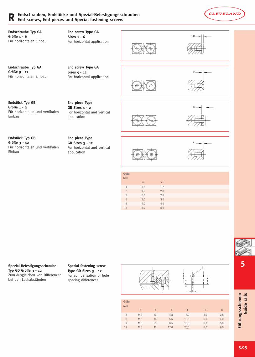
Größe
Size
a b c d e h
3 M 3 10 4,8 5,2 3,0 2,5
6 M 5 16 5,5 10,5 5,0 4,0
9 M 6 25 8,5 16,5 6,0 5,0
12 M 8 40 17,0 23,0 8,0 6,0
5.05
R Endschrauben, Endstücke und Spezial-BefestigungsschraubenEnd screws, End pieces and Special fastening screws
a1
a1
Endschraube Typ GAGröße 1 - 6Für horizontalen Einbau
End screw Type GASizes 1 - 6For horizontal application
Endschraube Typ GAGröße 9 - 12Für horizontalen Einbau
End screw Type GASizes 9 - 12For horizontal application
a2
a2
Endstück Typ GBGröße 1 - 2Für horizontalen und vertikalenEinbau
End piece TypeGB Sizes 1 - 2For horizontal and verticalapplication
Endstück Typ GBGröße 3 - 12Für horizontalen und vertikalenEinbau
End piece TypeGB Sizes 3 - 12For horizontal and verticalapplication
Größe
Size
a1 a2
1 1,2 1,7
2 1,5 2,0
3 2,0 2,0
6 3,0 3,0
9 4,0 4,0
12 5,0 5,0
h
bc
d
a
e
Spezial-BefestigungsschraubeTyp GD Größe 3 - 12Zum Ausgleichen von Differenzenbei den Lochabständen
Special fastening screwType GD Sizes 3 - 12For compensation of holespacing differences
6
Führungsschienen
Guide
rails
5
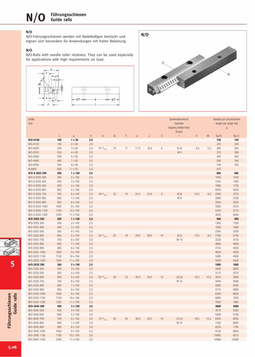
N/O FührungsschienenGuide rails
N/ON/O-Führungsschienen werden mit Nadelkäfigen bestückt undeignen sich besonders für Anwendungen mit hoher Belastung.
N/ON/O-Rails with needle roller retainers. They can be used especiallyfor applications with high requirements on load.
N/O
Größe (Gewindekernloch) Gewicht pro Einzelschiene
Size Gewinde weight per single trail
(tapping drilled hole) g
thread
L g D A B F J1 J C f V M Typ N Typ ON/O-6100 100 1 x 50 2,0 145 155N/O-6150 150 2 x 50 2,0 220 230
N/O-6200 200 3 x 50 2,0 31+0-0,3 15 11 17,5 16,0 6 (5,4) 9,5 5,2 295 305
N/O-6250 250 4 x 50 2,0 M 6 370 380
N/O-6300 300 5 x 50 2,0 445 455
N/O-6400 400 7 x 50 2,0 595 595
N/O-6500 500 9 x 50 2,0 745 755
N-6600 600 11 x 50 2,0 815
N/O-9 2025 200 200 1 x 100 2,0 685 695N/O-9 2025 300 300 2 x 100 2,0 1020 1030
N/O-9 2025 400 400 3 x 100 2,0 1355 1365
N/O-9 2025 500 500 4 x 100 2,0 1690 1700
N/O-9 2025 600 600 5 x 100 2,0 2025 2035
N/O-9 2025 700 700 6 x 100 2,0 44+0-0,3 22 15 24,5 24,0 9 (6,8) 10,5 6,2 2360 2370
N/O-9 2025 800 800 7 x 100 2,0 M 8 2695 2705
N/O-9 2025 900 900 8 x 100 2,0 3030 3040
N/O-9 2025 1000 1000 9 x 100 2,0 3365 3375
N/O-9 2025 1100 1100 10 x 100 2,0 3700 3710
N/O-9 2025 1200 1200 11 x 100 2,0 4035 4045
N/O-2025 200 200 1 x 100 2,0 900 900N/O-2025 300 300 2 x 100 2,0 1365 1350
N/O-2025 400 400 3 x 100 2,0 1830 1800
N/O-2025 500 500 4 x 100 2,0 2295 2250
N/O-2025 600 600 5 x 100 2,0 52+0-0,3 25 18 29,0 28,0 10 (8,5) 13,5 8,2 2760 2700
N/O-2025 700 700 6 x 100 2,0 M 10 3225 3150
N/O-2025 800 800 7 x 100 2,0 3690 3600
N/O-2025 900 900 8 x 100 2,0 4155 4050
N/O-2025 1000 1000 9 x 100 2,0 4620 4500
N/O-2025 1100 1100 10 x 100 2,0 5085 4950
N/O-2025 1200 1200 11 x 100 2,0 5550 5400
N/O-2535 300 300 2 x 100 2,5 1905 1965N/O-2535 400 400 3 x 100 2,5 2540 2620
N/O-2535 500 500 4 x 100 2,5 3175 3275
N/O-2535 600 600 5 x 100 2,5 62+0-0,3 30 22 35,0 34,0 12 (10,5) 16,5 10,2 3810 3930
N/O-2535 700 700 6 x 100 2,5 M 12 4445 4585
N/O-2535 800 800 7 x 100 2,5 5080 5240
N/O-2535 900 900 8 x 100 2,5 5715 5895
N/O-2535 1000 1000 9 x 100 2,5 6350 6650
N/O-2535 1100 1100 10 x 100 2,5 6985 7205
N/O-2535 1200 1200 11 x 100 2,5 7620 7860
N/O-3045 400 400 3 x 100 3,0 3660 3460N/O-3045 500 500 4 x 100 3,0 4575 4325
N/O-3045 600 600 5 x 100 3,0 5490 5190
N/O-3045 700 700 6 x 100 3,0 74+0-0,3 35 25 40,0 42,5 14 (12,5) 18,5 12,2 6405 6055
N/O-3045 800 800 7 x 100 3,0 M 14 7320 6920
N/O-3045 900 900 8 x 100 3,0 8235 7785
N/O-3045 1000 1000 9 x 100 3,0 9150 8650
N/O-3045 1100 1100 10 x 100 3,0 10065 9515
N/O-3045 1200 1200 11 x 100 3,0 10980 10380
L
g/2gg/2
øD
J1
F
V
BM
C
f
J
A
Führungsschienen
Guide
rails
5.06
5
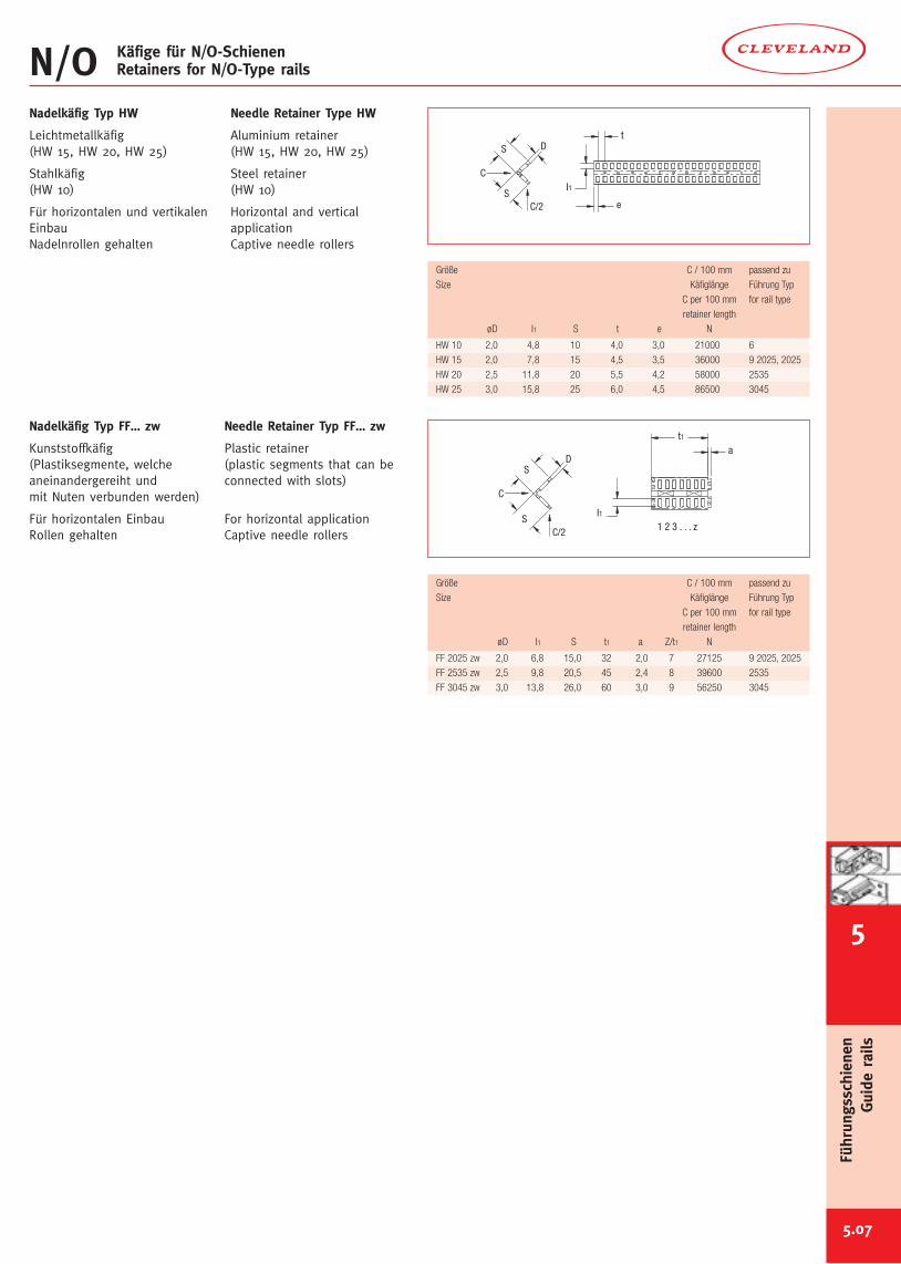
Größe C / 100 mm passend zu
Size Käfiglänge Führung Typ
C per 100 mm for rail type
retainer length
øD I1 S t1 a Z/t1 N
FF 2025 zw 2,0 6,8 15,0 32 2,0 7 27125 9 2025, 2025
FF 2535 zw 2,5 9,8 20,5 45 2,4 8 39600 2535
FF 3045 zw 3,0 13,8 26,0 60 3,0 9 56250 3045
Größe C / 100 mm passend zu
Size Käfiglänge Führung Typ
C per 100 mm for rail type
retainer length
øD I1 S t e N
HW 10 2,0 4,8 10 4,0 3,0 21000 6
HW 15 2,0 7,8 15 4,5 3,5 36000 9 2025, 2025
HW 20 2,5 11,8 20 5,5 4,2 58000 2535
HW 25 3,0 15,8 25 6,0 4,5 86500 3045
5.07
N/O Käfige für N/O-SchienenRetainers for N/O-Type rails
1 2 3 . . . zI1
t1a
DS
S
C
C/2
t
e
I1
DS
SC/2
C
Nadelkäfig Typ HW
Leichtmetallkäfig(HW 15, HW 20, HW 25)
Stahlkäfig(HW 10)
Für horizontalen und vertikalenEinbauNadelnrollen gehalten
Needle Retainer Type HW
Aluminium retainer(HW 15, HW 20, HW 25)
Steel retainer(HW 10)
Horizontal and verticalapplicationCaptive needle rollers
Nadelkäfig Typ FF… zw
Kunststoffkäfig(Plastiksegmente, welcheaneinandergereiht undmit Nuten verbunden werden)
Für horizontalen EinbauRollen gehalten
Needle Retainer Typ FF… zw
Plastic retainer(plastic segments that can beconnected with slots)
For horizontal applicationCaptive needle rollers
6
Führungsschienen
Guide
rails
5
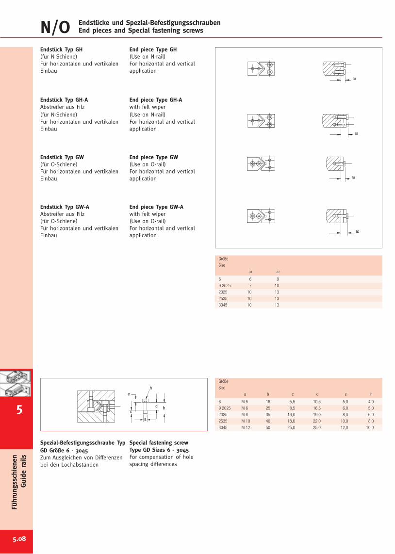
Größe
Size
a b c d e h
6 M 5 16 5,5 10,5 5,0 4,0
9 2025 M 6 25 8,5 16,5 6,0 5,0
2025 M 8 35 16,0 19,0 8,0 6,0
2535 M 10 40 18,0 22,0 10,0 8,0
3045 M 12 50 25,0 25,0 12,0 10,0
Größe
Size
a1 a2
6 6 9
9 2025 7 10
2025 10 13
2535 10 13
3045 10 13
5.08
a2
a1
a2
a1
Endstück Typ GH(für N-Schiene)Für horizontalen und vertikalenEinbau
Endstück Typ GH-AAbstreifer aus Filz(für N-Schiene)Für horizontalen und vertikalenEinbau
Endstück Typ GW(für O-Schiene)Für horizontalen und vertikalenEinbau
Endstück Typ GW-AAbstreifer aus Filz(für O-Schiene)Für horizontalen und vertikalenEinbau
End piece Type GH(Use on N-rail)For horizontal and verticalapplication
End piece Type GH-Awith felt wiper(Use on N-rail)For horizontal and verticalapplication
End piece Type GW(Use on O-rail)For horizontal and verticalapplication
End piece Type GW-Awith felt wiper(Use on O-rail)For horizontal and verticalapplication
h
b
e
dc
a
Spezial-Befestigungsschraube TypGD Größe 6 - 3045Zum Ausgleichen von Differenzenbei den Lochabständen
Special fastening screwType GD Sizes 6 - 3045For compensation of holespacing differences
N/O Endstücke und Spezial-BefestigungsschraubenEnd pieces and Special fastening screws
Führungsschienen
Guide
rails
5
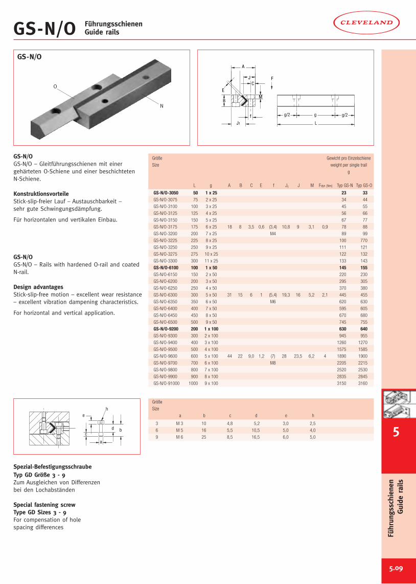
5.09
GS-N/O FührungsschienenGuide rails
GS-N/OGS-N/O – Gleitführungsschienen mit einergehärteten O-Schiene und einer beschichtetenN-Schiene.
KonstruktionsvorteileStick-slip-freier Lauf – Austauschbarkeit –sehr gute Schwingungsdämpfung.
Für horizontalen und vertikalen Einbau.
GS-N/OGS-N/O – Rails with hardened O-rail and coatedN-rail.
Design advantagesStick-slip-free motion – excellent wear resistance– excellent vibration dampening characteristics.
For horizontal and vertical application.
GS-N/O
L
g/2gg/2
J1
BM
C
f
J
A
E
h
b
e
dc
a
Spezial-BefestigungsschraubeTyp GD Größe 3 - 9Zum Ausgleichen von Differenzenbei den Lochabständen
Special fastening screwType GD Sizes 3 - 9For compensation of holespacing differences
Größe
Size
a b c d e h
3 M 3 10 4,8 5,2 3,0 2,5
6 M 5 16 5,5 10,5 5,0 4,0
9 M 6 25 8,5 16,5 6,0 5,0
6
Führungsschienen
Guide
rails
5
Größe Gewicht pro Einzelschiene
Size weight per single trail
g
L g A B C E f J1 J M Fdyn [Nm] Typ GS-N Typ GS-O
GS-N/O-3050 50 1 x 25 23 33GS-N/O-3075 75 2 x 25 34 44
GS-N/O-3100 100 3 x 25 45 55
GS-N/O-3125 125 4 x 25 56 66
GS-N/O-3150 150 5 x 25 67 77
GS-N/O-3175 175 6 x 25 18 8 3,5 0,6 (3,4) 10,8 9 3,1 0,9 78 88
GS-N/O-3200 200 7 x 25 M4 89 99
GS-N/O-3225 225 8 x 25 100 770
GS-N/O-3250 250 9 x 25 111 121
GS-N/O-3275 275 10 x 25 122 132
GS-N/O-3300 300 11 x 25 133 143
GS-N/O-6100 100 1 x 50 145 155GS-N/O-6150 150 2 x 50 220 230
GS-N/O-6200 200 3 x 50 295 305
GS-N/O-6250 250 4 x 50 370 380
GS-N/O-6300 300 5 x 50 31 15 6 1 (5,4) 19,3 16 5,2 2,1 445 455
GS-N/O-6350 350 6 x 50 M6 620 630
GS-N/O-6400 400 7 x 50 595 605
GS-N/O-6450 450 8 x 50 670 680
GS-N/O-6500 500 9 x 50 745 755
GS-N/O-9200 200 1 x 100 630 640GS-N/O-9300 300 2 x 100 945 955
GS-N/O-9400 400 3 x 100 1260 1270
GS-N/O-9500 500 4 x 100 1575 1585
GS-N/O-9600 600 5 x 100 44 22 9,0 1,2 (7) 28 23,5 6,2 4 1890 1900
GS-N/O-9700 700 6 x 100 M8 2205 2215
GS-N/O-9800 800 7 x 100 2520 2530
GS-N/O-9900 900 8 x 100 2835 2845
GS-N/O-91000 1000 9 x 100 3150 3160
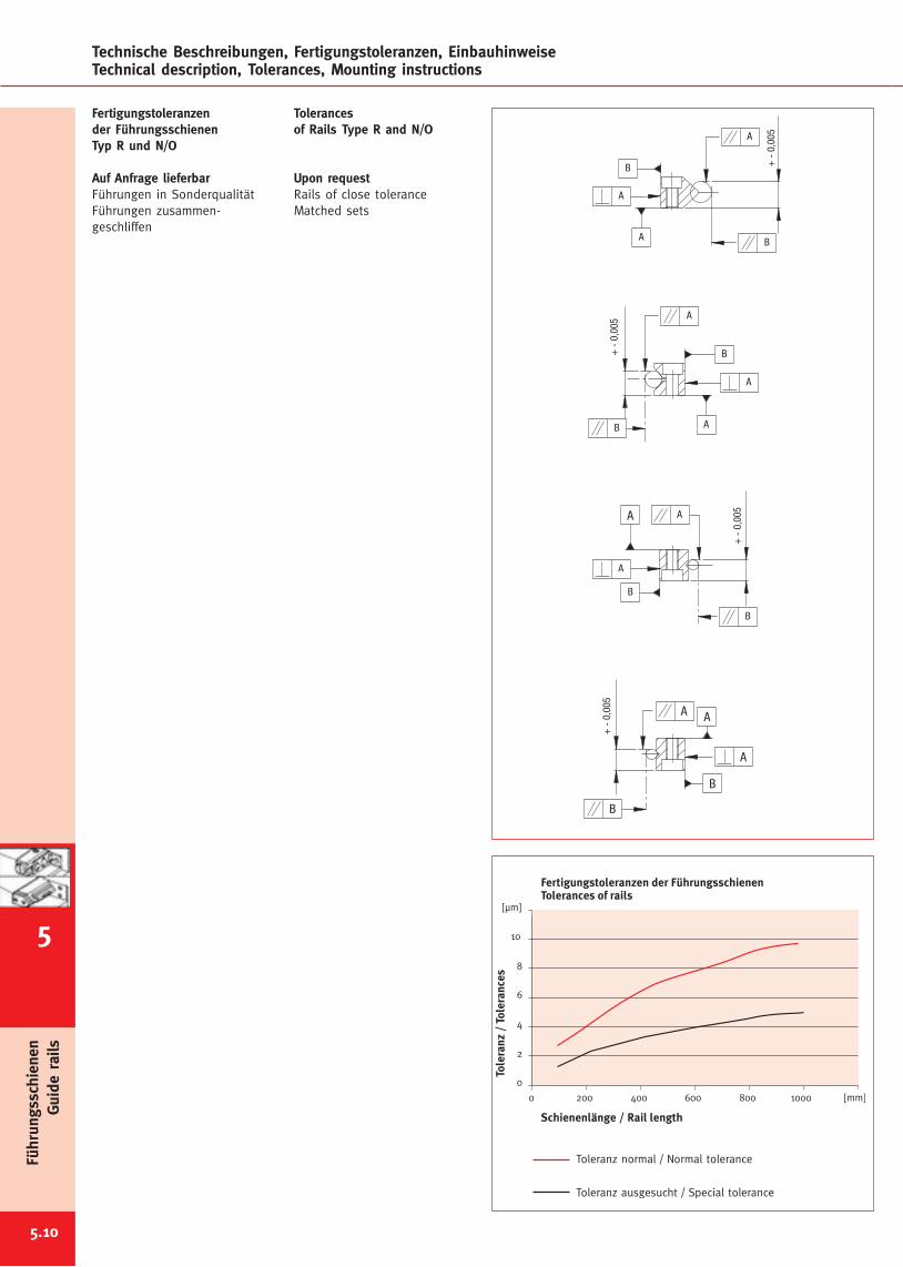
5.10
Technische Beschreibungen, Fertigungstoleranzen, EinbauhinweiseTechnical description, Tolerances, Mounting instructions
B
A
A
A
B
+-
0,00
5
A
B
A
B
A
+-
0,00
5
B
A
B
A
+-
0,00
5
B
A
A
B
A
+-
0,00
5
A
Fertigungstoleranzender FührungsschienenTyp R und N/O
Auf Anfrage lieferbarFührungen in SonderqualitätFührungen zusammen-geschliffen
Tolerancesof Rails Type R and N/O
Upon requestRails of close toleranceMatched sets
Führungsschienen
Guide
rails
Toleranz normal / Normal tolerance
Toleranz ausgesucht / Special tolerance
5
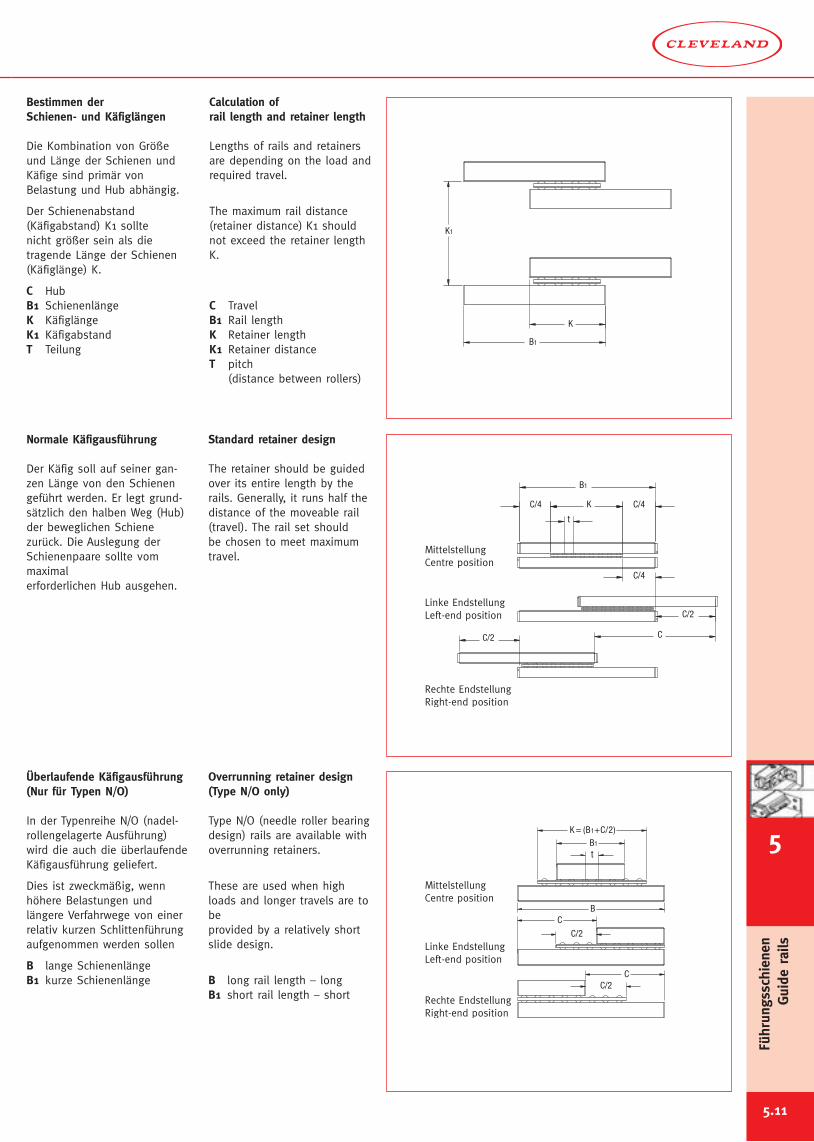
5.11
B1
K
K1
Rechte EndstellungRight-end position
Linke EndstellungLeft-end position
MittelstellungCentre position
C/2 C
C/2
C/4
t
K C/4
B1
C/4
t
C/2C
C/2
CB
K = (B1+C/2)B1
Rechte EndstellungRight-end position
Linke EndstellungLeft-end position
MittelstellungCentre position
Bestimmen derSchienen- und Käfiglängen
Die Kombination von Größeund Länge der Schienen undKäfige sind primär vonBelastung und Hub abhängig.
Der Schienenabstand(Käfigabstand) K1 solltenicht größer sein als dietragende Länge der Schienen(Käfiglänge) K.
C HubB1 SchienenlängeK KäfiglängeK1 KäfigabstandT Teilung
Calculation ofrail length and retainer length
Lengths of rails and retainersare depending on the load andrequired travel.
The maximum rail distance(retainer distance) K1 shouldnot exceed the retainer lengthK.
C TravelB1 Rail lengthK Retainer lengthK1 Retainer distanceT pitch
(distance between rollers)
Normale Käfigausführung
Der Käfig soll auf seiner gan-zen Länge von den Schienengeführt werden. Er legt grund-sätzlich den halben Weg (Hub)der beweglichen Schienezurück. Die Auslegung derSchienenpaare sollte vommaximalerforderlichen Hub ausgehen.
Standard retainer design
The retainer should be guidedover its entire length by therails. Generally, it runs half thedistance of the moveable rail(travel). The rail set shouldbe chosen to meet maximumtravel.
Überlaufende Käfigausführung(Nur für Typen N/O)
In der Typenreihe N/O (nadel-rollengelagerte Ausführung)wird die auch die überlaufendeKäfigausführung geliefert.
Dies ist zweckmäßig, wennhöhere Belastungen undlängere Verfahrwege von einerrelativ kurzen Schlittenführungaufgenommen werden sollen
B lange SchienenlängeB1 kurze Schienenlänge
Overrunning retainer design(Type N/O only)
Type N/O (needle roller bearingdesign) rails are available withoverrunning retainers.
These are used when highloads and longer travels are tobeprovided by a relatively shortslide design.
B long rail length – longB1 short rail length – short
6
Führungsschienen
Guide
rails
5
Berechnungsbeispiel(Schienenführung mit Rollen Typ 3)
Vorgaben
Führungsart rollengelagertVerschiebeweg Hub C 130 mmFührungsschienen Typ 3 ø3 mmTeilung t gemäß Tabelle 5 mmTragfähigkeit einer Rolle gemäß Tabelle 100 N
Ermitteln der Schienenlänge B1Verhältnis von Hub C zu Schienenlänge B1= C : B1= 1:1,5 bis 1:2= 130 : 195 bis 130 : 260ausgewählte lieferbare Schienelänge gemäß Tabelle= 225 mm (Typ R-3225)
Ermitteln der Käfiglänge K= Schienenlänge B1 – (Hub : 2)= B1 – (C : 2)= 225 – (130 : 2)= 160 mm
Ermitteln der Rollenanzahl je Käfig= Käfiglänge : Teilung= K : t= 160 : 5= 32 Rollen
Ermitteln der Tragfähigkeit einer Schienenführung(4 Schienen, 2 Käfige)= Anzahl der tragenden Rollen x Tragfähigkeit einer Rolle(Anzahl der tragenden Rollen = Summe aller Rollen : 2)
= 64 : 2 x 100 N= 32 x 100 N= 3.200 N
Example of calculation(Slide with rails type R3)
Required information
Type of bearing crossed roller bearingTravel C 130 mmRail Type 3 ø 3 mmpitch t according to table 5 mmLoad capacity of one roller according to table 100 N
Determination of rail length B1Proportion of travel C to rail length B1= C : B1= 1:1,5 up to 1:2= 130 : 195 up to 130 : 260chosen rail length according to table= 225 mm (Type R-3225)
Determination of retainer length K= Rail length B1 – (travel : 2)= B1 – (C : 2)= 225 – (130 : 2)= 160 mm
Determination of number of rollers per retainer= Retainer length : pitch= K : t= 160 : 5= 32 Rollers
Determination of the load capacity of a rail set(4 rails, 2 retainers)= Number of supporting rollers x load capacity of one roller(Number of supporting rollers = Total number of rollers : 2)
= 64 : 2 x 100 N= 32 x 100 N= 3.200 N
5.12
Technische Beschreibungen, Fertigungstoleranzen, EinbauhinweiseTechnical description, Tolerances, Mounting instructions
Führungsschienen
Guide
rails
5
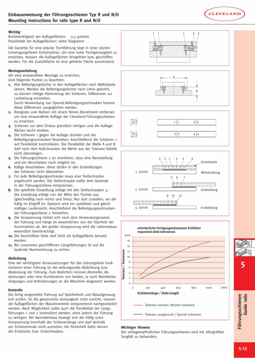
5.13
3211 1
B
A
Einbauanweisung der Führungsschienen Typ R und N/OMounting instructions for rails type R and N/O
WichtigRechtwinkligkeit der Auflageflächen: 0,3 µm/mmParallelität der Auflageflächen: siehe Diagramm
Die Garantie für eine präzise Tischführung liegt in einer starrenschwingungsfreien Konstruktion. Um eine hohe Tischgenauigkeit zuerreichen, müssen die Auflageflächen feingefräst bzw. geschliffenwerden. Für die Zustellfläche ist eine gefräste Fläche ausreichend.
MontageanleitungUm eine einwandfreie Montage zu erreichen,sind folgende Punkte zu beachten:1. Alle Befestigungslöcher in den Auflageflächen nach Maßtabelle
setzen. Werden die Befestigungslöcher nach Lehre gebohrt,so können infolge Härteverzug der Schienen, Differenzen zurLochteilung entstehen.Durch Verwendung von Spezial-Befestigungsschrauben könnendiese Differenzen ausgeglichen werden.
2. Restgrate vom Bohren mit einem feinen Abziehstein entfernenum eine einwandfreie Auflage der Cleveland-Führungsschienenzu erreichen.
3. Schienen vor dem Einbau gründlich reinigen und die Auflage-flächen leicht einölen.
4. Die Schienen 1 gegen die Auflage drücken und dieBefestigungsschrauben festziehen. Anschließend die Schienen 1auf Parallelität kontrollieren. Die Parallelität der Maße A und Bdarf nach dem Aufschrauben die Werte aus der Toleranz-Tabellenicht übersteigen.
5. Die Führungsschiene 2 so montieren, dass eine Nachstellungund ein Verschieben noch möglich ist.
6. Käfige einschieben: diese dürfen in den Endstellungender Schienen nicht überstehen.
7. Für jede Befestigungsschraube muss eine Stellschraubeangebracht werden. Die Stellschraube sollte dem Gewindein der Führungsschiene entsprechen.
8. Die spielfreie Einstellung erfolgt mit den Stellschrauben 3.Die Zustellung erfolgt von der Mitte des Tisches aus(gleichmäßig nach rechts und links). Nur dort zustellen, wo derKäfig im Eingriff ist. Dadurch wird ein spielfreier und gleich-mäßiger Lauferreicht. Anschließend die Befestigungsschraubender Führungsschiene 2 festziehen.
9. Die Vorspannung richtet sich nach dem Verwendungszweckder Führung und hängt im wesentlichen von der Starrheit derKonstruktion ab. Bei großer Vorspannung wird die Lebensdauerwesentlich beeinträchtigt.
10. Die beschriftete Seite darf nicht als Auflagefläche benutztwerden.
11. Bei zusammen geschliffenen Längsführungen ist auf dielaufende Nummerierung zu achten.
AbdichtungEine der wichtigsten Voraussetzungen für das störungsfreie Funk-tionieren einer Führung ist die wirkungsvolle Abdichtung bzw.Abdeckung der Führung. Zum Abdichten können Abstreifer, Ab-deckungen oder eine Kombination von beiden, je nach Betriebsbe-dingungen und Anforderungen an die Maschine eingesetzt werden.
KontrolleDie fertig eingestellte Führung auf Spielfreiheit und Ablaufgenauig-keit prüfen. Ist die gewünschte Genauigkeit nicht erreicht, müssendie Auflageflächen der Maschinenteile entsprechend nachgearbeitetwerden. Nach Möglichkeit sollte auch die Parallelität der Längs-führungen 1 und 2 kontrolliert werden, ohne jedoch die Führungzu zerlegen. Bei Normaleinbau bewegt sich der Käfig unterVorspannung innerhalb der Schienenlänge und darf deshalbam Schienenende nicht austreten. Als Sicherheit dafür dienendie Endstücke bzw. Endschrauben.
Wichtiger HinweisDie schlagempfindlichen Führungsschienen sind mit allergrößterSorgfalt zu behandeln.
3. Schritt
2. Schritt
1. Schritt
Endstellung
Endstellung
Mittelstellung
Zustellseite
108 12
7911
642135
Toleranz normal / Normal tolerance
Toleranz ausgesucht / Special tolerance
6
Führungsschienen
Guide
rails
5
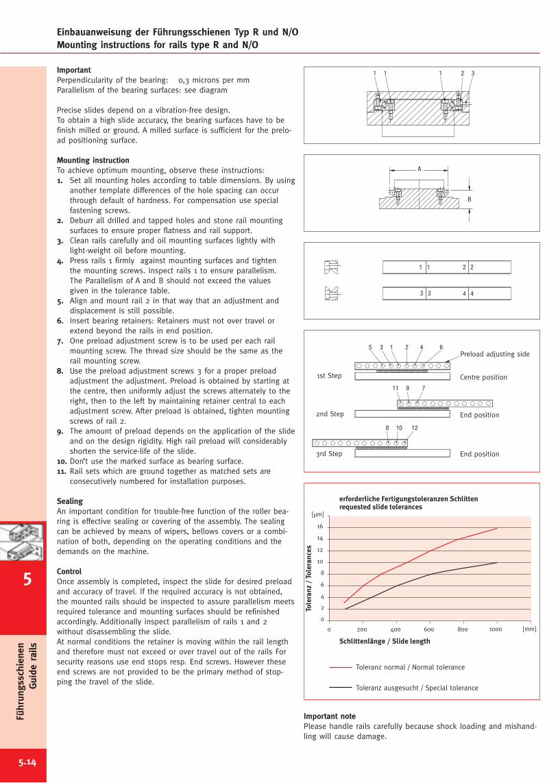
Einbauanweisung der Führungsschienen Typ R und N/OMounting instructions for rails type R and N/O
5.14
3211 1
B
A
ImportantPerpendicularity of the bearing: 0,3 microns per mmParallelism of the bearing surfaces: see diagram
Precise slides depend on a vibration-free design.To obtain a high slide accuracy, the bearing surfaces have to befinish milled or ground. A milled surface is sufficient for the prelo-ad positioning surface.
Mounting instructionTo achieve optimum mounting, observe these instructions:1. Set all mounting holes according to table dimensions. By using
another template differences of the hole spacing can occurthrough default of hardness. For compensation use specialfastening screws.
2. Deburr all drilled and tapped holes and stone rail mountingsurfaces to ensure proper flatness and rail support.
3. Clean rails carefully and oil mounting surfaces lightly withlight-weight oil before mounting.
4. Press rails 1 firmly against mounting surfaces and tightenthe mounting screws. Inspect rails 1 to ensure parallelism.The Parallelism of A and B should not exceed the valuesgiven in the tolerance table.
5. Align and mount rail 2 in that way that an adjustment anddisplacement is still possible.
6. Insert bearing retainers: Retainers must not over travel orextend beyond the rails in end position.
7. One preload adjustment screw is to be used per each railmounting screw. The thread size should be the same as therail mounting screw.
8. Use the preload adjustment screws 3 for a proper preloadadjustment the adjustment. Preload is obtained by starting atthe centre, then uniformly adjust the screws alternately to theright, then to the left by maintaining retainer central to eachadjustment screw. After preload is obtained, tighten mountingscrews of rail 2.
9. The amount of preload depends on the application of the slideand on the design rigidity. High rail preload will considerablyshorten the service-life of the slide.
10. Don’t use the marked surface as bearing surface.11. Rail sets which are ground together as matched sets are
consecutively numbered for installation purposes.
SealingAn important condition for trouble-free function of the roller bea-ring is effective sealing or covering of the assembly. The sealingcan be achieved by means of wipers, bellows covers or a combi-nation of both, depending on the operating conditions and thedemands on the machine.
ControlOnce assembly is completed, inspect the slide for desired preloadand accuracy of travel. If the required accuracy is not obtained,the mounted rails should be inspected to assure parallelism meetsrequired tolerance and mounting surfaces should be refinishedaccordingly. Additionally inspect parallelism of rails 1 and 2without disassembling the slide.At normal conditions the retainer is moving within the rail lengthand therefore must not exceed or over travel out of the rails Forsecurity reasons use end stops resp. End screws. However theseend screws are not provided to be the primary method of stop-ping the travel of the slide.
3rd Step
2nd Step
1st Step
End position
End position
Centre position
Preload adjusting side
108 12
7911
642135
Toleranz normal / Normal tolerance
Toleranz ausgesucht / Special tolerance
Important notePlease handle rails carefully because shock loading and mishand-ling will cause damage.
Führungsschienen
Guide
rails
5
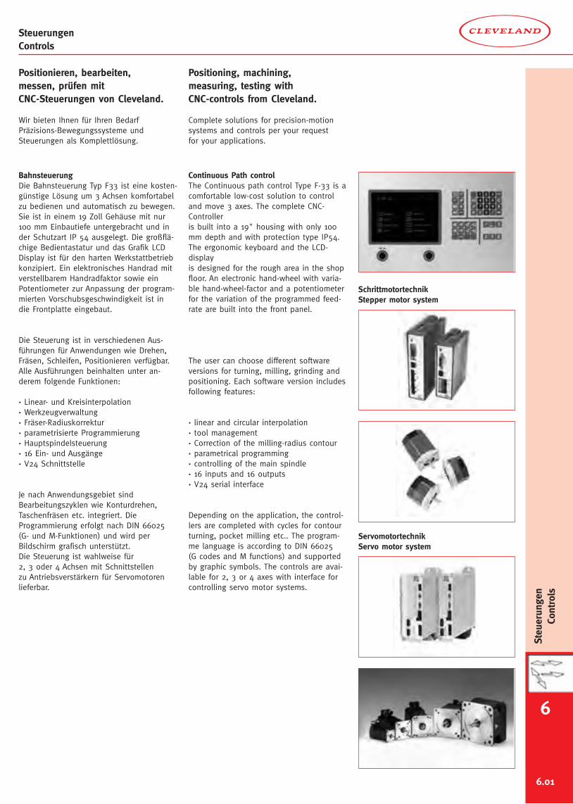
6.01
6
Steuerungen
Controls
BahnsteuerungDie Bahnsteuerung Typ F33 ist eine kosten-günstige Lösung um 3 Achsen komfortabelzu bedienen und automatisch zu bewegen.Sie ist in einem 19 Zoll Gehäuse mit nur100 mm Einbautiefe untergebracht und inder Schutzart IP 54 ausgelegt. Die großflä-chige Bedientastatur und das Grafik LCDDisplay ist für den harten Werkstattbetriebkonzipiert. Ein elektronisches Handrad mitverstellbarem Handradfaktor sowie einPotentiometer zur Anpassung der program-mierten Vorschubsgeschwindigkeit ist indie Frontplatte eingebaut.
Die Steuerung ist in verschiedenen Aus-führungen für Anwendungen wie Drehen,Fräsen, Schleifen, Positionieren verfügbar.Alle Ausführungen beinhalten unter an-derem folgende Funktionen:
· Linear- und Kreisinterpolation· Werkzeugverwaltung· Fräser-Radiuskorrektur· parametrisierte Programmierung· Hauptspindelsteuerung· 16 Ein- und Ausgänge· V24 Schnittstelle
Je nach Anwendungsgebiet sindBearbeitungszyklen wie Konturdrehen,Taschenfräsen etc. integriert. DieProgrammierung erfolgt nach DIN 66025(G- und M-Funktionen) und wird perBildschirm grafisch unterstützt.Die Steuerung ist wahlweise für2, 3 oder 4 Achsen mit Schnittstellenzu Antriebsverstärkern für Servomotorenlieferbar.
ServomotortechnikServo motor system
SchrittmotortechnikStepper motor system
Continuous Path controlThe Continuous path control Type F-33 is acomfortable low-cost solution to controland move 3 axes. The complete CNC-Controlleris built into a 19" housing with only 100mm depth and with protection type IP54.The ergonomic keyboard and the LCD-displayis designed for the rough area in the shopfloor. An electronic hand-wheel with varia-ble hand-wheel-factor and a potentiometerfor the variation of the programmed feed-rate are built into the front panel.
The user can choose different softwareversions for turning, milling, grinding andpositioning. Each software version includesfollowing features:
· linear and circular interpolation· tool management· Correction of the milling-radius contour· parametrical programming· controlling of the main spindle· 16 inputs and 16 outputs· V24 serial interface
Depending on the application, the control-lers are completed with cycles for contourturning, pocket milling etc.. The program-me language is according to DIN 66025(G codes and M functions) and supportedby graphic symbols. The controls are avai-lable for 2, 3 or 4 axes with interface forcontrolling servo motor systems.
Positionieren, bearbeiten,messen, prüfen mitCNC-Steuerungen von Cleveland.
Wir bieten Ihnen für Ihren BedarfPräzisions-Bewegungssysteme undSteuerungen als Komplettlösung.
Positioning, machining,measuring, testing withCNC-controls from Cleveland.
Complete solutions for precision-motionsystems and controls per your requestfor your applications.
SteuerungenControls

6.02
SteuerungenControls
Liste der G-Funktionen FräsenG00 Positionieren im EilgangG01 LinearinterpolationG02 Kreis im UhrzeigersinnG03 Kreis im GegenuhrzeigersinnG04 VerweilzeitG05 Kreis mit Radius im UhrzeigersinnG06 Kreis mit Radius im GegenuhrzeigersinnG07 Kreis mit WinkelG08 Asynchrone BewegungG09 Restweg löschenG10 Ecke runden (Option)G11 Zusatzfunktion F, S, TG13 Zusatz M-FunktionG17 Ebene XYG18 Ebene XZG19 Ebene YZG20 ProgrammsprungG22 Programmaufruf mit WiederholungG23 Programmsprung mit BedingungG29 Freier ZyklusG36 WerkzeugwechselG40 Radiuskorrektur AUSG41 Werkzeugkorrektur LINKSG42 Werkzeugkorrektur RECHTSG53 Nullpunktversatz AUSG54 Nullpunktversatz EING55 NullpunktversatzG58 Nullpunkt speichernG59 T abspeichernG67 Software Endschalter –G68 Software Endschalter +G74 Referenzpunkt fahrenG75 Skalenfaktor ANG76 Skalenfaktor AUSG78 Freier ZyklusG79 Freier ZyklusG80 Zyklus AUSG81 Freier modaler ZyklusG82 TieflochbohrenG83 GewindebohrenG84 NutG85 Rechtecktasche / RandG86 KreisteilungG87 Kreistasche / RandG88 Linearteilung im RaumG90 AbsolutmaßG91 KettenmaßG92 Istwert setzen
List of G-Functions millingG00 Rapid traverseG01 Linear interpolationG02 Circle CWG03 Circle CCWG04 Dwell timeG05 Circle with radius CWG06 Circle with radius CCWG07 Circle with angleG08 Asynchronous movementG09 Skip rest of travelG10 Corner rounding (Option)G11 Additional functions F, S, TG13 Additional M-functionsG17 Plane XYG18 Plane XZG19 Plane YZG20 Jump to programmeG22 Call programmeG23 Call / Jump with conditionG29 Free cycleG36 Tool changeG40 Radius correction OFFG41 Radius correction LEFTG42 Radius correction RIGHTG53 Displacement OFFG54 Displacement ONG55 DisplacementG58 Memorize Zero pointG59 Put T in memoryG67 Software limit switch –G68 Software limit switch +G74 Reference pointG75 Scale factor ONG76 Scale factor OFFG78 Free cycleG79 Free cycleG80 Cycle OFFG81 Free modal cycleG81 Deep drilling ( MODAL )G83 Tap drillingG84 Free cycleG85 Pocket cycleG86 Circle segmentationG87 Circle pocketG88 Linear segmentationG90 Absolute inputG91 Incremental inputG92 Set actual value
Steuerungen
Controls
6
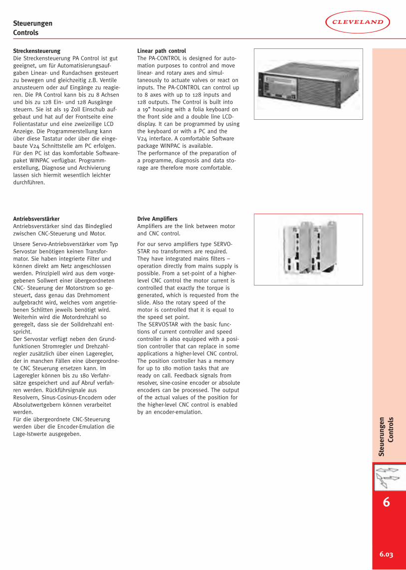
6.03
StreckensteuerungDie Streckensteuerung PA Control ist gutgeeignet, um für Automatisierungsauf-gaben Linear- und Rundachsen gesteuertzu bewegen und gleichzeitig z.B. Ventileanzusteuern oder auf Eingänge zu reagie-ren. Die PA Control kann bis zu 8 Achsenund bis zu 128 Ein- und 128 Ausgängesteuern. Sie ist als 19 Zoll Einschub auf-gebaut und hat auf der Frontseite eineFolientastatur und eine zweizeilige LCDAnzeige. Die Programmerstellung kannüber diese Tastatur oder über die einge-baute V24 Schnittstelle am PC erfolgen.Für den PC ist das komfortable Software-paket WINPAC verfügbar. Programm-erstellung, Diagnose und Archivierunglassen sich hiermit wesentlich leichterdurchführen.
AntriebsverstärkerAntriebsverstärker sind das Bindegliedzwischen CNC-Steuerung und Motor.
Unsere Servo-Antriebsverstärker vom TypServostar benötigen keinen Transfor-mator. Sie haben integrierte Filter undkönnen direkt am Netz angeschlossenwerden. Prinzipiell wird aus dem vorge-gebenen Sollwert einer übergeordnetenCNC- Steuerung der Motorstrom so ge-steuert, dass genau das Drehmomentaufgebracht wird, welches vom angetrie-benen Schlitten jeweils benötigt wird.Weiterhin wird die Motordrehzahl sogeregelt, dass sie der Solldrehzahl ent-spricht.Der Servostar verfügt neben den Grund-funktionen Stromregler und Drehzahl-regler zusätzlich über einen Lageregler,der in manchen Fällen eine übergeordne-te CNC Steuerung ersetzen kann. ImLageregler können bis zu 180 Verfahr-sätze gespeichert und auf Abruf verfah-ren werden. Rückführsignale ausResolvern, Sinus-Cosinus-Encodern oderAbsolutwertgebern können verarbeitetwerden.Für die übergeordnete CNC-Steuerungwerden über die Encoder-Emulation dieLage-Istwerte ausgegeben.
Linear path controlThe PA-CONTROL is designed for auto-mation purposes to control and movelinear- and rotary axes and simul-taneously to actuate valves or react oninputs. The PA-CONTROL can control upto 8 axes with up to 128 inputs and128 outputs. The Control is built intoa 19’’ housing with a folia keyboard onthe front side and a double line LCD-display. It can be programmed by usingthe keyboard or with a PC and theV24 interface. A comfortable Softwarepackage WINPAC is available.The performance of the preparation ofa programme, diagnosis and data sto-rage are therefore more comfortable.
Drive AmplifiersAmplifiers are the link between motorand CNC control.
For our servo amplifiers type SERVO-STAR no transformers are required.They have integrated mains filters –operation directly from mains supply ispossible. From a set-point of a higher-level CNC control the motor current iscontrolled that exactly the torque isgenerated, which is requested from theslide. Also the rotary speed of themotor is controlled that it is equal tothe speed set point.The SERVOSTAR with the basic func-tions of current controller and speedcontroller is also equipped with a posi-tion controller that can replace in someapplications a higher-level CNC control.The position controller has a memoryfor up to 180 motion tasks that areready on call. Feedback signals fromresolver, sine-cosine encoder or absoluteencoders can be processed. The outputof the actual values of the position forthe higher-level CNC control is enabledby an encoder-emulation.
SteuerungenControls
6
Steuerungen
Controls
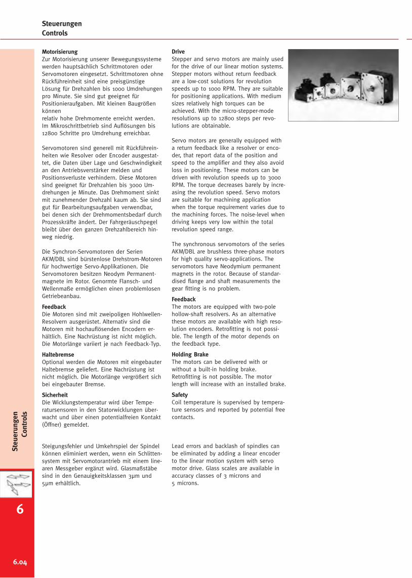
6.04
MotorisierungZur Motorisierung unserer Bewegungssystemewerden hauptsächlich Schrittmotoren oderServomotoren eingesetzt. Schrittmotoren ohneRückführeinheit sind eine preisgünstigeLösung für Drehzahlen bis 1000 Umdrehungenpro Minute. Sie sind gut geeignet fürPositionieraufgaben. Mit kleinen Baugrößenkönnenrelativ hohe Drehmomente erreicht werden.Im Mikroschrittbetrieb sind Auflösungen bis12800 Schritte pro Umdrehung erreichbar.
Servomotoren sind generell mit Rückführein-heiten wie Resolver oder Encoder ausgestat-tet, die Daten über Lage und Geschwindigkeitan den Antriebsverstärker melden undPositionsverluste verhindern. Diese Motorensind geeignet für Drehzahlen bis 3000 Um-drehungen je Minute. Das Drehmoment sinktmit zunehmender Drehzahl kaum ab. Sie sindgut für Bearbeitungsaufgaben verwendbar,bei denen sich der Drehmomentsbedarf durchProzesskräfte ändert. Der Fahrgeräuschpegelbleibt über den ganzen Drehzahlbereich hin-weg niedrig.
Die Synchron-Servomotoren der SerienAKM/DBL sind bürstenlose Drehstrom-Motorenfür hochwertige Servo-Applikationen. DieServomotoren besitzen Neodym Permanent-magnete im Rotor. Genormte Flansch- undWellenmaße ermöglichen einen problemlosenGetriebeanbau.
FeedbackDie Motoren sind mit zweipoligen Hohlwellen-Resolvern ausgerüstet. Alternativ sind dieMotoren mit hochauflösenden Encodern er-hältlich. Eine Nachrüstung ist nicht möglich.Die Motorlänge variiert je nach Feedback-Typ.
HaltebremseOptional werden die Motoren mit eingebauterHaltebremse geliefert. Eine Nachrüstung istnicht möglich. Die Motorlänge vergrößert sichbei eingebauter Bremse.
SicherheitDie Wicklungstemperatur wird über Tempe-ratursensoren in den Statorwicklungen über-wacht und über einen potentialfreien Kontakt(Öffner) gemeldet.
Steigungsfehler und Umkehrspiel der Spindelkönnen eliminiert werden, wenn ein Schlitten-system mit Servomotorantrieb mit einem line-aren Messgeber ergänzt wird. Glasmaßstäbesind in den Genauigkeitsklassen 3µm und5µm erhältlich.
DriveStepper and servo motors are mainly usedfor the drive of our linear motion systems.Stepper motors without return feedbackare a low-cost solutions for revolutionspeeds up to 1000 RPM. They are suitablefor positioning applications. With mediumsizes relatively high torques can beachieved. With the micro-stepper-moderesolutions up to 12800 steps per revo-lutions are obtainable.
Servo motors are generally equipped witha return feedback like a resolver or enco-der, that report data of the position andspeed to the amplifier and they also avoidloss in positioning. These motors can bedriven with revolution speeds up to 3000RPM. The torque decreases barely by incre-asing the revolution speed. Servo motorsare suitable for machining applicationwhen the torque requirement varies due tothe machining forces. The noise-level whendriving keeps very low within the totalrevolution speed range.
The synchronous servomotors of the seriesAKM/DBL are brushless three-phase motorsfor high quality servo-applications. Theservomotors have Neodymium permanentmagnets in the rotor. Because of standar-dised flange and shaft measurements thegear fitting is no problem.
FeedbackThe motors are equipped with two-polehollow-shaft resolvers. As an alternativethese motors are available with high reso-lution encoders. Retrofitting is not possi-ble. The length of the motor depends onthe feedback type.
Holding BrakeThe motors can be delivered with orwithout a built-in holding brake.Retrofitting is not possible. The motorlength will increase with an installed brake.
SafetyCoil temperature is supervised by tempera-ture sensors and reported by potential freecontacts.
Lead errors and backlash of spindles canbe eliminated by adding a linear encoderto the linear motion system with servomotor drive. Glass scales are available inaccuracy classes of 3 microns and5 microns.
SteuerungenControls
Steuerungen
Controls
6
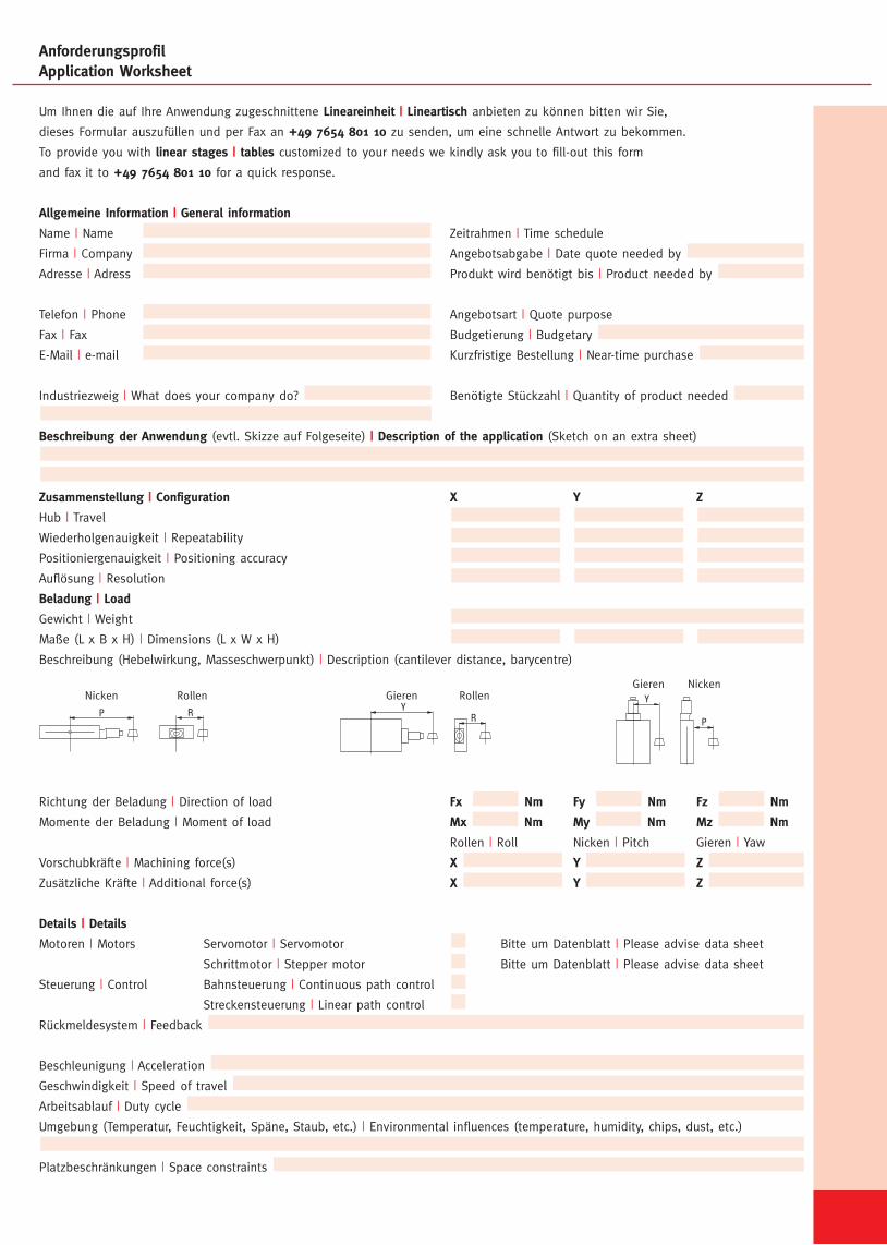
AnforderungsprofilApplication Worksheet
Um Ihnen die auf Ihre Anwendung zugeschnittene Lineareinheit | Lineartisch anbieten zu können bitten wir Sie,
dieses Formular auszufüllen und per Fax an +49 7654 801 10 zu senden, um eine schnelle Antwort zu bekommen.
To provide you with linear stages | tables customized to your needs we kindly ask you to fill-out this form
and fax it to +49 7654 801 10 for a quick response.
Allgemeine Information | General information
Name | Name Zeitrahmen | Time schedule
Firma | Company Angebotsabgabe | Date quote needed by
Adresse | Adress Produkt wird benötigt bis | Product needed by
Telefon | Phone Angebotsart | Quote purpose
Fax | Fax Budgetierung | Budgetary
E-Mail | e-mail Kurzfristige Bestellung | Near-time purchase
Industriezweig | What does your company do? Benötigte Stückzahl | Quantity of product needed
Beschreibung der Anwendung (evtl. Skizze auf Folgeseite) | Description of the application (Sketch on an extra sheet)
Zusammenstellung | Configuration X Y Z
Hub | Travel
Wiederholgenauigkeit | Repeatability
Positioniergenauigkeit | Positioning accuracy
Auflösung | Resolution
Beladung | Load
Gewicht | Weight
Maße (L x B x H) | Dimensions (L x W x H)
Beschreibung (Hebelwirkung, Masseschwerpunkt) | Description (cantilever distance, barycentre)
Richtung der Beladung | Direction of load Fx Nm Fy Nm Fz Nm
Momente der Beladung | Moment of load Mx Nm My Nm Mz Nm
Rollen | Roll Nicken | Pitch Gieren | Yaw
Vorschubkräfte | Machining force(s) X Y Z
Zusätzliche Kräfte | Additional force(s) X Y Z
Details | Details
Motoren | Motors Servomotor | Servomotor Bitte um Datenblatt | Please advise data sheet
Schrittmotor | Stepper motor Bitte um Datenblatt | Please advise data sheet
Steuerung | Control Bahnsteuerung | Continuous path control
Streckensteuerung | Linear path control
Rückmeldesystem | Feedback
Beschleunigung | Acceleration
Geschwindigkeit | Speed of travel
Arbeitsablauf | Duty cycle
Umgebung (Temperatur, Feuchtigkeit, Späne, Staub, etc.) | Environmental influences (temperature, humidity, chips, dust, etc.)
Platzbeschränkungen | Space constraints
RollenNicken
RP
Rollen
R
GierenY
GierenY
Nicken
P
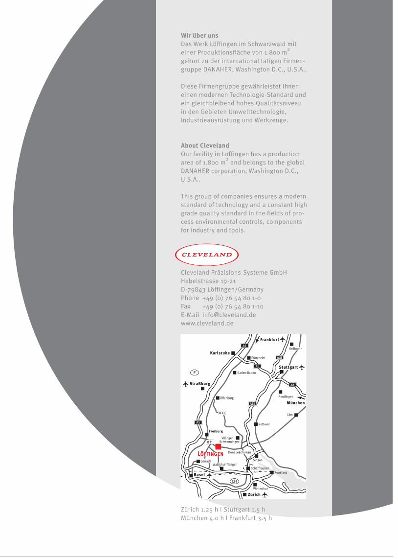


![Consensus APAT Statement Antibiotikatherapie · APAT weit verbreitet; so entfallen z.B. an der „Cleveland Clinic“ 25% aller infektiologischen Konsultationen auf APATs [14]. Eine](https://img.pdfslide.org/doc/110x75/5e22fb50d338ec510f7986b4/consensus-apat-statement-an-apat-weit-verbreitet-so-entfallen-zb-an-der-acleveland.jpg)