Embed Size (px)
Citation preview
LMT Tools
ISO- und Tangential-Wendeschneidplatten
LMT Tools
ISO and tangential indexable inserts
www.lmt-tools.com
VorwortForeword
Sehr geehrte Kunden und Interessenten,
wer im Wettbewerb bestehen will, muss ebenso effizient wie
flexibel auf rasch wechselnde Anforderungen reagieren können.
Daher ist es umso wichtiger auf einen zuverlässigen Werkzeug-
lieferanten setzen zu können. Die LMT Tools bietet Ihnen dafür
ein umfangreiches Produktprogramm an Standard- oder Sonder-
werkzeugen.
Mit dem Katalog „ISO- und Tangential-Wendeschneidplatten“
erweitern wir unsere Katalogreihe mit einem ausgewählten
Programm an Standard-ISO Wendeplatten sowie tangentialen
Schneidplatten. Weitere nicht im Katalog genannte Schneidstoffe
und Geometrien, können direkt über unsere Vertriebsmitarbeiter
angefragt werden.
Auf eine produktive Zusammenarbeit.
Ihre LMT Tool Systems
Dear customers and potential customers,
in order to survive in a competitive market, one must be able
to react both efficiently and flexibly to swiftly changing require-
ments. It is therefore all the more important to be able to depend
on a reliable tool supplier. LMT Tools thus offers you an extensive
range of standard or special tools.
With the “ISO and tangential indexable inserts” catalog we are
expanding our catalog series by a selected range of standard ISO
and tangential inserts. Further geometries and cutting grades that
are not included in this catalogue, can be requested directly at
our sales offices.
We look forward to a productive cooperation.
Your LMT Tool Systems
shop.lmt-tools.de
Der LMT Tools Online-Shop!Für Kunden aus Deutschland bieten wir unser Standard-
Produktprogramm nun auch in unserem neuen Online-Shop
an. Nutzen Sie die speziellen Vorteile und bestellen Sie Ihre
Produkte bequem im LMT Tools Online-Shop.
Registrieren Sie sich noch heute!
© by LMT Tool Systems GmbH & Co. KGNachdruck, auch auszugsweise, ist nur mit unserer Zustimmung gestattet. Alle Rechte vorbehalten. Irrtümer, Satz- oder Druckfehler berechtigen nicht zu irgend welchen Ansprüchen.
Abbildungen, Ausführungen und Maße entsprechen dem neuesten Stand bei Herausgabe dieses Kataloges. Technische Änderungen müssen vorbehalten sein.
Die bildliche Darstellung der Produkte muss nicht in jedem Falle und in allen Einzelheiten dem tatsächlichen Aussehen entsprechen.
Bildquellen: Nataliya Hora, adimas, Alterfalter, Rudy Balasko, Fotolia; zhu difeng, Shutterstock; Keyzo, Berlin; studio thomas schmitz, Hamburg; LMT GmbH & Co. KG
This publication may not be reprinted in whole or part without our express permission. All right reserved. No rights may be derived from any errors in content or from typographical
or typesetting errors. Diagrams, features and dimensions represent the current status on the date of issue of this catalog. We reserve the right to make technical changes.
The visual appearance of the products may not necessarily correspond to the actual appearance in all cases or in every detail.
Sources: Nataliya Hora, adimas, Alterfalter, Rudy Balasko, Fotolia; zhu difeng, Shutterstock; Keyzo, Berlin; studio thomas schmitz, Hamburg; LMT GmbH & Co. KG
2 Das UnternehmenThe company
3 Die LMT Tools Gruppe – Das ExpertenteamThe LMT Tools Group – Team of experts
6 Der LMT Tools WerkzeugserviceThe LMT Tools tool service
7 Die LMT Group AcademyThe LMT Group Academy
8 Bezeichnungssystem Wendeplatten und SchneidstoffeDesignation system inserts and cutting materials
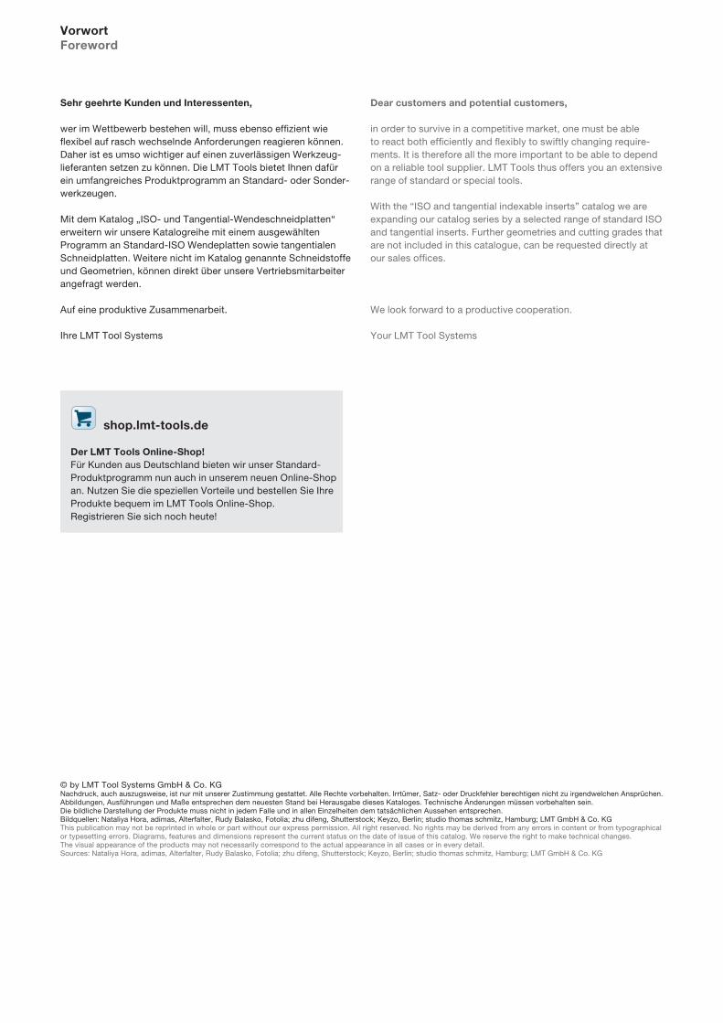
ISO-WendeschneidplattenISO Indexable inserts
SpezifischeWendeschneidplattenSpecific Indexable inserts
TangentialWendeschneidplattenTangentialIndexable inserts
FeindreheinsätzeMAC und ISOAdjustable cartridgesMAC and ISO
www.lmt-tools.com2
Das UnternehmenThe company
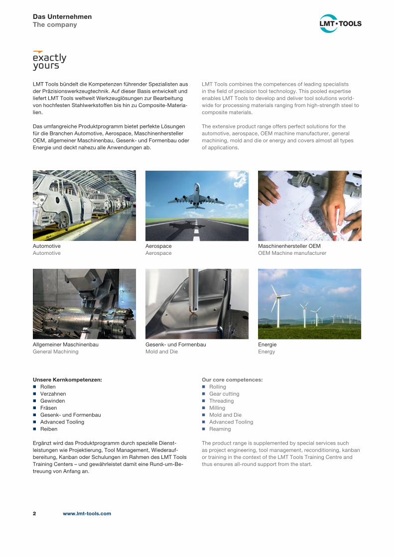
LMT Tools bündelt die Kompetenzen führender Spezialisten aus
der Präzisionswerkzeugtechnik. Auf dieser Basis entwickelt und
liefert LMT Tools weltweit Werkzeuglösungen zur Bearbeitung
von hochfesten Stahlwerkstoffen bis hin zu Composite-Materia-
lien.
Das umfangreiche Produktprogramm bietet perfekte Lösungen
für die Branchen Automotive, Aerospace, Maschinenhersteller
OEM, allgemeiner Maschinenbau, Gesenk- und Formenbau oder
Energie und deckt nahezu alle Anwendungen ab.
LMT Tools combines the competences of leading specialists
in the field of precision tool technology. This pooled expertise
enables LMT Tools to develop and deliver tool solutions world-
wide for processing materials ranging from high-strength steel to
composite materials.
The extensive product range offers perfect solutions for the
automotive, aerospace, OEM machine manufacturer, general
machining, mold and die or energy and covers almost all types
of appli cations.
Our core competences: ◼ Rolling
◼ Gear cutting
◼ Threading
◼ Milling
◼ Mold and Die
◼ Advanced Tooling
◼ Reaming
The product range is supplemented by special services such
as project engineering, tool management, reconditioning, kanban
or training in the context of the LMT Tools Training Centre and
thus ensures all-round support from the start.
Unsere Kernkompetenzen: ◼ Rollen
◼ Verzahnen
◼ Gewinden
◼ Fräsen
◼ Gesenk- und Formenbau
◼ Advanced Tooling
◼ Reiben
Ergänzt wird das Produktprogramm durch spezielle Dienst-
leistungen wie Projektierung, Tool Management, Wiederauf-
bereitung, Kanban oder Schulungen im Rahmen des LMT Tools
Training Centers – und gewährleistet damit eine Rund-um-Be-
treuung von Anfang an.
Automotive
Automotive
Aerospace
Aerospace
Maschinenhersteller OEM
OEM Machine manufacturer
Allgemeiner Maschinenbau
General Machining
Energie
Energy
Gesenk- und Formenbau
Mold and Die

www.lmt-tools.com 3
Die LMT ToolsThe LMT Tools
Weltweite Präsenz der LMT ToolsWorldwide presence of LMT Tools
● LMT Tools Produktionsstandorte: Deutschland: LMT Fette l Schwarzenbek, LMT Kieninger l Lahr
Frankreich: LMT Belin l Lavancia
USA: LMT Onsrud l Waukegan
Indien: LMT India l Pune
● Die LMT Tools ist mit eigenen Vertriebsgesellschaften und Servicestandorten in folgenden Ländern vertreten:
Europa: Deutschland, England, Frankreich, Österreich,
Rumänien, Russland, Spanien, Tschechische Republik.
Amerika: Brasilien, Mexiko, USA.
Asien/Australien: China, Indien, Korea.
● Die LMT Tools hat Vertriebspartner in folgenden Ländern:
In Europa: Belgien, Dänemark, Finnland, Israel, Italien,
Kroatien, Lettland, Litauen, Niederlande, Norwegen, Polen,
Portugal, Schweden, Schweiz, Slowakei, Slowenien, Türkei,
Ukraine, Ungarn.
In Asien/Australien: Australien, Indonesien, Iran, Japan,
Malaysia, Neuseeland, Singapur, Taiwan, Thailand, Vietnam.
In Afrika: Südafrika.
In Amerika: Argentinien.
● LMT Tools production sites: Germany: LMT Fette l Schwarzenbek, LMT Kieninger l Lahr
France: LMT Belin l Lavancia
USA: LMT Onsrud l Waukegan
India: LMT India l Pune
● LMT Tools has its own sales and service organisations in the following countries:
Europe: Austria, Czech Republic, England, France, Germany,
Romania, Russia, Spain.
America: Brazil, Mexico, USA.
Asia/Australia: China, India, Korea.
● LMT Tools has sales partners in the following countries:
In Europe: Belgium, Croatia, Denmark, Finland, Hungary,
Israel, Italy, Latvia, Lithuania, Netherlands, Norway, Poland,
Portugal, Slovakia, Slovenia, Sweden, Switzerland, Turkey,
Ukraine.
In Asia/Australia: Australia, Indonesia, Iran, Japan, Malaysia,
New Zealand, Singapore, Taiwan, Thailand, Vietnam.
In Africa: South Africa.
In America: Argentina.
LMT ONSRUDUSA
LMT BELINFRANCE
LMT KIENINGERGERMANY
LMT FETTEGERMANY
LMT BRAZIL
LMT UK
LMT USA
LMT MEXICO
LMT FRANCE
LMT RUSSIA
LMT CHINA
LMT KOREA
LMT CZECH REPUBLIC
LMT GERMANY
LMT Tools Niederlassungen und Servicestandorte /
LMT Tools subsidiaries and service organisations
LMT Tools Produktionsstandorte / LMT Tools production sites
LMT ROMANIA
LMT INDIA
LMT INDIA
LMT SPAIN LMT AUSTRIA
www.lmt-tools.com4
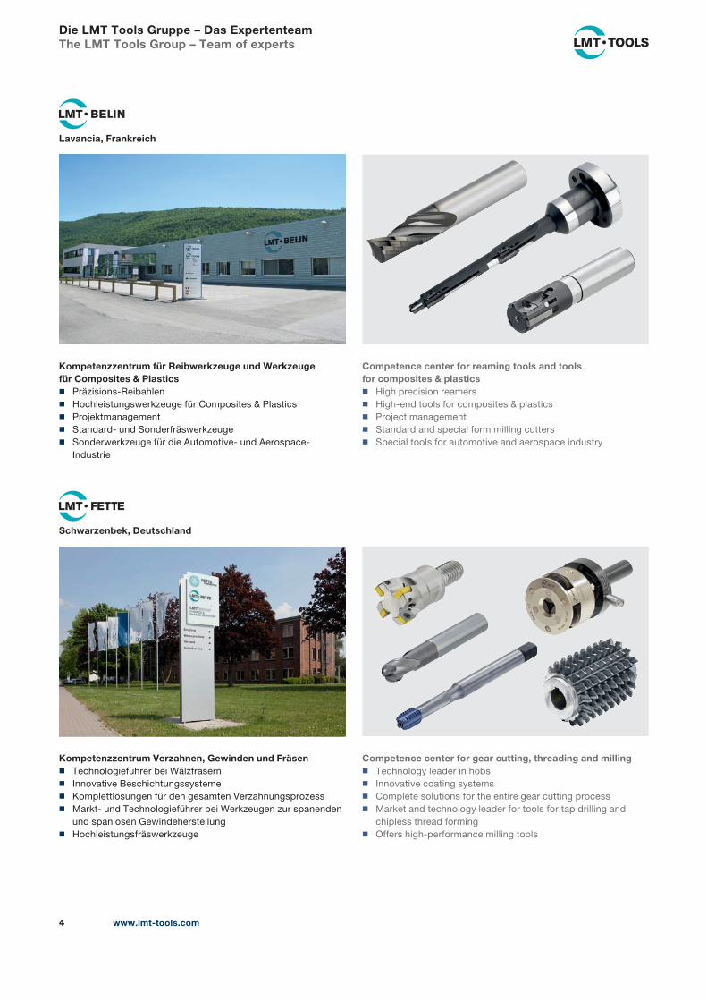
Lavancia, Frankreich
Competence center for reaming tools and toolsfor composites & plastics
◼ High precision reamers
◼ High-end tools for composites & plastics
◼ Project management
◼ Standard and special form milling cutters
◼ Special tools for automotive and aerospace industry
Kompetenzzentrum für Reibwerkzeuge und Werkzeugefür Composites & Plastics
◼ Präzisions-Reibahlen
◼ Hochleistungswerkzeuge für Composites & Plastics
◼ Projektmanagement
◼ Standard- und Sonderfräswerkzeuge
◼ Sonderwerkzeuge für die Automotive- und Aerospace-
Industrie
Schwarzenbek, Deutschland
Kompetenzzentrum Verzahnen, Gewinden und Fräsen ◼ Technologieführer bei Wälzfräsern
◼ Innovative Beschichtungssysteme
◼ Komplettlösungen für den gesamten Verzahnungsprozess
◼ Markt- und Technologieführer bei Werkzeugen zur spanenden
und spanlosen Gewindeherstellung
◼ Hochleistungsfräswerkzeuge
Competence center for gear cutting, threading and milling ◼ Technology leader in hobs
◼ Innovative coating systems
◼ Complete solutions for the entire gear cutting process
◼ Market and technology leader for tools for tap drilling and
chipless thread forming
◼ Offers high-performance milling tools
Die LMT Tools Gruppe – Das ExpertenteamThe LMT Tools Group – Team of experts
www.lmt-tools.com 5
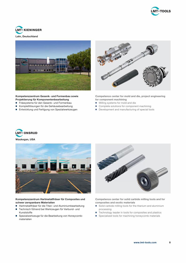
Lahr, Deutschland
Kompetenzzentrum Gesenk- und Formenbau sowie Projektierung für Komponentenbearbeitung
◼ Frässysteme für den Gesenk- und Formenbau
◼ Komplettlösungen für die Gehäusebearbeitung
◼ Entwicklung und Fertigung von Spezialwerkzeugen
Waukegan, USA
Competence center for mold and die, project engineering for component machining
◼ Milling systems for mold and die
◼ Complete solutions for component machining
◼ Development and manufacturing of special tools
Competence center for solid carbide milling tools and for composites and exotic materials
◼ Solid carbide milling tools for the titanium and aluminium
processing
◼ Technology leader in tools for composites and plastics
◼ Specialized tools for machining honeycomb materials
Kompetenzzentrum Hartmetallfräser für Composites und schwer zerspanbare Materialien
◼ Hartmetallfräser für die Titan- und Aluminiumbearbeitung
◼ Technisch führend bei Werkzeugen für Verbund- und
Kunststoffe
◼ Spezialwerkzeuge für die Bearbeitung von Honeycomb-
materialien
www.lmt-tools.com6
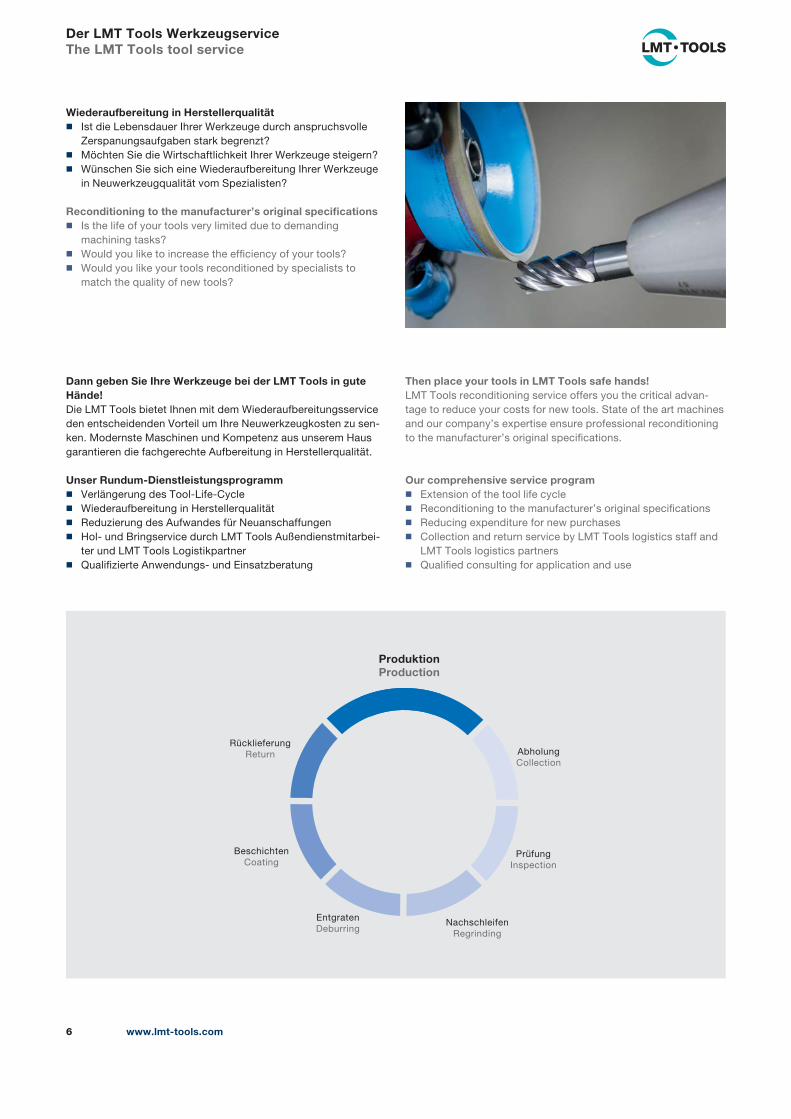
Der LMT Tools WerkzeugserviceThe LMT Tools tool service
Wiederaufbereitung in Herstellerqualität ◼ Ist die Lebensdauer Ihrer Werkzeuge durch anspruchsvolle
Zerspanungsaufgaben stark begrenzt?
◼ Möchten Sie die Wirtschaftlichkeit Ihrer Werkzeuge steigern?
◼ Wünschen Sie sich eine Wiederaufbereitung Ihrer Werkzeuge
in Neuwerkzeugqualität vom Spezialisten?
Reconditioning to the manufacturer’s original specifications ◼ Is the life of your tools very limited due to demanding
machining tasks?
◼ Would you like to increase the efficiency of your tools?
◼ Would you like your tools reconditioned by specialists to
match the quality of new tools?
Then place your tools in LMT Tools safe hands!LMT Tools reconditioning service offers you the critical advan-
tage to reduce your costs for new tools. State of the art machines
and our company’s expertise ensure professional reconditioning
to the manufacturer’s original specifications.
Our comprehensive service program ◼ Extension of the tool life cycle
◼ Reconditioning to the manufacturer’s original specifications
◼ Reducing expenditure for new purchases
◼ Collection and return service by LMT Tools logistics staff and
LMT Tools logistics partners
◼ Qualified consulting for application and use
ProduktionProduction
Entgraten
Deburring
Prüfung
Inspection
Rücklieferung
Return Abholung
Collection
Beschichten
Coating
Nachschleifen
Regrinding
Dann geben Sie Ihre Werkzeuge bei der LMT Tools in gute Hände!Die LMT Tools bietet Ihnen mit dem Wiederaufbereitungsservice
den entscheidenden Vorteil um Ihre Neuwerkzeugkosten zu sen-
ken. Modernste Maschinen und Kompetenz aus unserem Haus
garantieren die fachgerechte Aufbereitung in Hersteller qualität.
Unser Rundum-Dienstleistungsprogramm ◼ Verlängerung des Tool-Life-Cycle
◼ Wiederaufbereitung in Herstellerqualität
◼ Reduzierung des Aufwandes für Neuanschaffungen
◼ Hol- und Bringservice durch LMT Tools Außendienstmitarbei-
ter und LMT Tools Logistikpartner
◼ Qualifizierte Anwendungs- und Einsatzberatung
www.lmt-tools.com 7
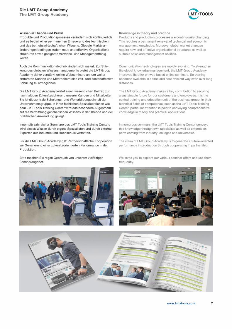
Wissen in Theorie und PraxisProdukte und Produktionsprozesse verändern sich kontinuierlich
und es bedarf einer permanenten Erneuerung des technischen
und des betriebswirtschaftlichen Wissens. Globale Marktver-
änderungen bedingen zudem neue und effektive Organisations-
strukturen sowie geeignete Vertriebs- und Managementfähig-
keiten.
Auch die Kommunikationstechnik ändert sich rasant. Zur Stär-
kung des globalen Wissensmanagements bietet die LMT Group
Academy daher verstärkt online Webseminare an, um weiter
entfernten Kunden und Mitarbeitern eine zeit- und kosteneffektive
Schulung zu ermöglichen.
Die LMT Group Academy leistet einen wesentlichen Beitrag zur
nachhaltigen Zukunftssicherung unserer Kunden und Mitarbeiter.
Sie ist die zentrale Schulungs- und Weiterbildungseinheit der
Unternehmensgruppe. In ihren fachlichen Spezialbereichen wie
dem LMT Tools Training Center wird das besondere Augenmerk
auf die Vermittlung ganzheitlichen Wissens in der Theorie und der
praktischen Anwendung gelegt.
Innerhalb zahlreicher Seminare des LMT Tools Training Centers
wird dieses Wissen durch eigene Spezialisten und durch externe
Experten aus Industrie und Hochschule vermittelt.
Für die LMT Group Academy gilt: Partnerschaftliche Kooperation
zur Generierung einer zukunftsorientierten Performance in der
Produktion.
Bitte machen Sie regen Gebrauch von unserem vielfältigen
Seminarangebot.
Knowledge in theory and practiceProducts and production processes are continuously changing.
This requires a permanent renewal of technical and economic
management knowledge. Moreover global market changes
require new and effective organizational structures as well as
suitable sales and management abilities.
Communication technologies are rapidly evolving. To strengthen
the global knowledge management, the LMT Group Academy
improved its offer on web based online seminars. So training
becomes available in a time and cost efficient way even over long
distances.
The LMT Group Academy makes a key contribution to securing
a sustainable future for our customers and employees. It is the
central training and education unit of the business group. In their
technical fields of competence, such as the LMT Tools Training
Center, particular attention is paid to conveying comprehensive
knowledge in theory and practical applications.
In numerous seminars, the LMT Tools Training Center conveys
this knowledge through own specialists as well as external ex-
perts coming from industry, colleges and universities.
The claim of LMT Group Academy is to generate a future-oriented
performance in production through cooperating in partnership.
We invite you to explore our various seminar offers and use them
frequently.
Die LMT Group AcademyThe LMT Group Academy
www.lmt-tools.com8
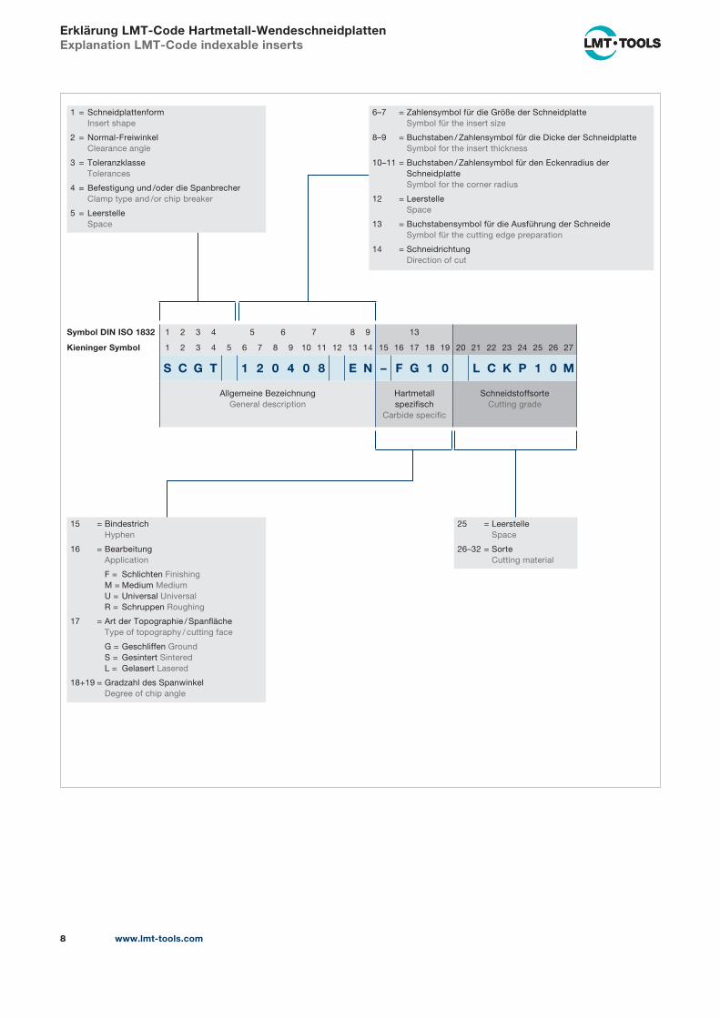
Erklärung LMT-Code Hartmetall-WendeschneidplattenExplanation LMT-Code indexable inserts
1 = Schneidplattenform
Insert shape
2 = Normal-Freiwinkel
Clearance angle
3 = Toleranzklasse
Tolerances
4 = Befestigung und /oder die Spanbrecher
Clamp type and /or chip breaker
5 = Leerstelle
Space
6–7 = Zahlensymbol für die Größe der Schneidplatte
Symbol für the insert size
8–9 = Buchstaben / Zahlensymbol für die Dicke der Schneidplatte
Symbol for the insert thickness
10–11 = Buchstaben / Zahlensymbol für den Eckenradius der
Schneidplatte
Symbol for the corner radius
12 = Leerstelle
Space
13 = Buchstabensymbol für die Ausführung der Schneide
Symbol für the cutting edge preparation
14 = Schneidrichtung
Direction of cut
25 = Leerstelle
Space
26–32 = Sorte
Cutting material
15 = Bindestrich
Hyphen
16 = Bearbeitung
Application
F = Schlichten Finishing
M = Medium Medium
U = Universal Universal
R = Schruppen Roughing
17 = Art der Topographie / Spanfläche
Type of topography / cutting face
G = Geschliffen Ground
S = Gesintert Sintered
L = Gelasert Lasered
18+19 = Gradzahl des Spanwinkel
Degree of chip angle
Symbol DIN ISO 1832 1 2 3 4 5 6 7 8 9 13
Kieninger Symbol 1 2 3 4 5 6 7 8 9 10 11 12 13 14 15 16 17 18 19 20 21 22 23 24 25 26 27
S C G T 1 2 0 4 0 8 E N – F G 1 0 L C K P 1 0 M
Allgemeine Bezeichnung
General description
Hartmetall
spezifisch
Carbide specific
Schneidstoffsorte
Cutting grade
www.lmt-tools.com 9
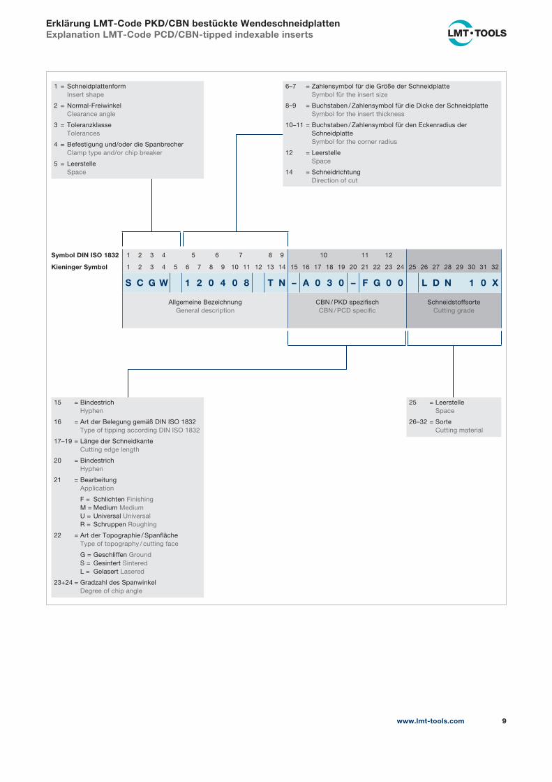
Erklärung LMT-Code PKD/CBN bestückte WendeschneidplattenExplanation LMT-Code PCD/CBN-tipped indexable inserts
1 = Schneidplattenform
Insert shape
2 = Normal-Freiwinkel
Clearance angle
3 = Toleranzklasse
Tolerances
4 = Befestigung und/oder die Spanbrecher
Clamp type and/or chip breaker
5 = Leerstelle
Space
6–7 = Zahlensymbol für die Größe der Schneidplatte
Symbol für the insert size
8–9 = Buchstaben / Zahlensymbol für die Dicke der Schneidplatte
Symbol for the insert thickness
10–11 = Buchstaben / Zahlensymbol für den Eckenradius der
Schneidplatte
Symbol for the corner radius
12 = Leerstelle
Space
14 = Schneidrichtung
Direction of cut
25 = Leerstelle
Space
26–32 = Sorte
Cutting material
15 = Bindestrich
Hyphen
16 = Art der Belegung gemäß DIN ISO 1832
Type of tipping according DIN ISO 1832
17–19 = Länge der Schneidkante
Cutting edge length
20 = Bindestrich
Hyphen
21 = Bearbeitung
Application
F = Schlichten Finishing
M = Medium Medium
U = Universal Universal
R = Schruppen Roughing
22 = Art der Topographie / Spanfläche
Type of topography / cutting face
G = Geschliffen Ground
S = Gesintert Sintered
L = Gelasert Lasered
23+24 = Gradzahl des Spanwinkel
Degree of chip angle
Symbol DIN ISO 1832 1 2 3 4 5 6 7 8 9 10 11 12
Kieninger Symbol 1 2 3 4 5 6 7 8 9 10 11 12 13 14 15 16 17 18 19 20 21 22 23 24 25 26 27 28 29 30 31 32
S C G W 1 2 0 4 0 8 T N – A 0 3 0 – F G 0 0 L D N 1 0 X
Allgemeine Bezeichnung
General description
CBN / PKD spezifisch
CBN / PCD specific
Schneidstoffsorte
Cutting grade
www.lmt-tools.com10
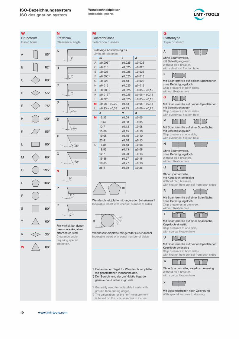
ISO-BezeichnungssystemISO designation system
WendeschneidplattenIndexable inserts
WGrundform
Basic form
A 85°
B 82°
C 80°
D 55°
E 75°
H 120°
K 55°
L 90°
M 86°
O 135°
P 108°
R –
S 90°
T 60°
V 35°
W 80°
NFreiwinkel
Clearence angle
A
B
C
D
E
F
G
N
P
O
Freiwinkel, bei denen
besondere Angaben
erforderlich sind.
Clearance angle
requiring special
indication.
GPlattentype
Type of insert
A
F
G
M
N
Q
R
T
U
W
X
MToleranzklasse
Tolerance classes
Zulässige Abweichung für
Limits of tolerance
m s d
A ±0,0051) ±0,025 ±0,025
C ±0,013 ±0,025 ±0,025
E ±0,025 ±0,025 ±0,025
F ±0,0051) ±0,025 ±0,013
G ±0,025 ±0,13 ±0,025
H ±0,013 ±0,025 ±0,013
J ±0,0051) ±0,025 ±0,05 – ±0,15
K ±0,0131) ±0,025 ±0,05 – ±0,15
L ±0,025 ±0,025 ±0,05 – ±0,15
M ±0,08 – ±0,20 ±0,13 ±0,05 – ±0,15
U ±0,13 – ±0,38 ±0,13 ±0,08 – ±0,25
d m d
M 6,35 ±0,08 ±0,05
9,52 ±0,08 ±0,05
12,7 ±0,13 ±0,08
15,88 ±0,15 ±0,10
19,05 ±0,15 ±0,10
25,4 ±0,18 ±0,13
U 6,35 ±0,13 ±0,08
9,52 ±0,13 ±0,08
12,7 ±0,20 ±0,13
15,88 ±0,27 ±0,18
19,05 ±0,27 ±0,18
25,4 ±0,38 ±0,25
Wendeschneidplatte mit ungerader Seitenanzahl
Indexable insert with unequal number of sides
Wendeschneidplatte mit gerader Seitenanzahl
Indexable insert with equal number of sides
1) Gelten in der Regel für Wendeschneidplatten
mit geschliffenen Planschneiden.
*) Der Berechnung der „m“-Maße liegt der
genaue Zoll-Radius zugrunde.
1) Generally used for indexable inserts with
ground face cutting edges.
*) The calculation for the “m” measurement
is based on the precise radius in inches.
3°
5°
7°
15°
20°
25°
30°
0°
11°
α°
m
d
m*)
Ohne Spanformrille,
mit Befestigungsloch
Without chip breaker,
with cylindrical fixation hole
Mit Spanformrille auf beiden Spanflächen,
ohne Befestigungsloch
Chip breakers at both sides,
without fixation hole
Mit Spanformrille auf beiden Spanflächen,
mit Befestigungsloch
Chip breakers at both sides,
with cylindrical fixation hole
Mit Spanformrille auf einer Spanfläche,
mit Befestigungsloch
Chip breakers at one side,
with cylindrical fixation hole
Ohne Spanformrille,
ohne Befestigungsloch
Without chip breakers,
without fixation hole
Ohne Spanformrille,
mit Kegelloch beidseitig
Without chip breakers,
with fixation hole conical from both sides
Mit Spanformrille auf einer Spanfläche,
ohne Befestigungsloch
Chip breakeres at one side,
without fixation hole
Mit Spanformrille auf einer Spanfläche,
Kegelloch einseitig
Chip breakers at one side,
with conical fixation hole
Mit Spanformrille auf beiden Spanflächen,
Kegelloch beidseitig
Chip breakers at both sides,
with fixation hole conical from both sides
Ohne Spanformrille, Kegelloch einseitig
Without chip breaker,
with conical fixation hole
Mit Besonderheiten nach Zeichnung
With special features to drawing
www.lmt-tools.com 11
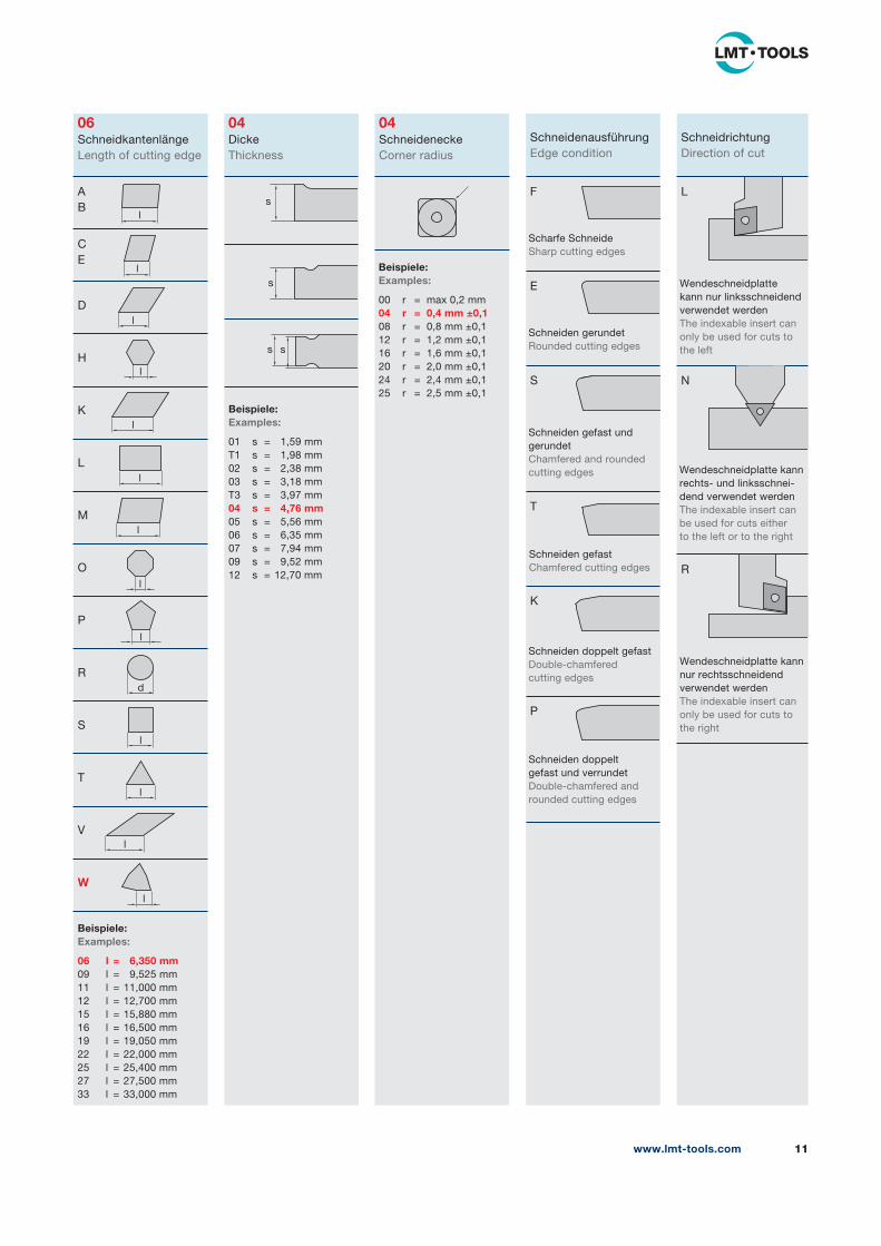
06Schneidkantenlänge
Length of cutting edge
A
B
C
E
D
H
K
L
M
O
P
R
S
T
V
W
04Dicke
Thickness
04Schneidenecke
Corner radius
Schneidenausführung
Edge condition
F
E
S
T
K
P
Schneidrichtung
Direction of cut
L
N
R
Beispiele:Examples:
06 l = 6,350 mm 09 l = 9,525 mm
11 l = 11,000 mm
12 l = 12,700 mm
15 l = 15,880 mm
16 l = 16,500 mm
19 l = 19,050 mm
22 l = 22,000 mm
25 l = 25,400 mm
27 l = 27,500 mm
33 l = 33,000 mm
Beispiele:Examples:
01 s = 1,59 mm
T1 s = 1,98 mm
02 s = 2,38 mm
03 s = 3,18 mm
T3 s = 3,97 mm
04 s = 4,76 mm 05 s = 5,56 mm
06 s = 6,35 mm
07 s = 7,94 mm
09 s = 9,52 mm
12 s = 12,70 mm
Beispiele:Examples:
00 r = max 0,2 mm
04 r = 0,4 mm ±0,1 08 r = 0,8 mm ±0,1
12 r = 1,2 mm ±0,1
16 r = 1,6 mm ±0,1
20 r = 2,0 mm ±0,1
24 r = 2,4 mm ±0,1
25 r = 2,5 mm ±0,1
Scharfe Schneide
Sharp cutting edges
Schneiden gerundet
Rounded cutting edges
Schneiden gefast und
gerundet
Chamfered and rounded
cutting edges
Schneiden gefast
Chamfered cutting edges
Schneiden doppelt gefast
Double-chamfered
cutting edges
Schneiden doppelt
gefast und verrundet
Double-chamfered and
rounded cutting edges
Wendeschneidplatte
kann nur linksschneidend
verwendet werden
The indexable insert can
only be used for cuts to
the left
Wendeschneidplatte kann
rechts- und linksschnei-
dend verwendet werden
The indexable insert can
be used for cuts either
to the left or to the right
Wendeschneidplatte kann
nur rechtsschneidend
verwendet werden
The indexable insert can
only be used for cuts to
the right
l
l
l
l
l
l
l
l
l
d
l
l
l
l
s
s
s s
www.lmt-tools.com12
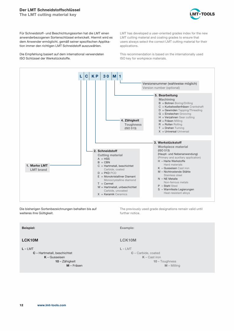
Der LMT SchneidstoffschlüsselThe LMT cutting material key
Für Schneidstoff- und Beschichtungssorten hat die LMT einen
anwenderbezogenen Sortenschlüssel ent wickelt. Hiermit wird es
dem Anwender ermöglicht, gemäß seiner spezifischen Applika-
tion immer den richtigen LMT Schneidstoff auszuwählen.
Die Empfehlung basiert auf dem international verwendeten
ISO Schlüssel der Werkstückstoffe.
LMT has developed a user-oriented grades index for the new
LMT cutting material and coating grades to ensure that
users always select the correct LMT cutting material for their
applications.
This recommendation is based on the internationally used
ISO key for workpiece materials.
L C K P 3 0 M 1
5. Bearbeitung Machining B = Bohren Boring/Drilling
C = Kurbelwellenfräsen Crankshaft
D = Gewinden Tapping/Threading
G = Einstechen Grooving
H = Verzahnen Gear cutting
M = Fräsen Milling
R = Rollen Rolling
T = Drehen Turning
X = Universal Universal
3. Werkstückstoff Workpiece material (ISO 513)
(Haupt- und Nebenanwendung)
(Primary and auxiliary application)
H – Harte Werkstoffe
Hard materials
K – Gusseisen Cast iron
M – Nichtrostende Stähle
Stainless steel
N – NE Metalle
Non-ferrous metals
P – Stahl Steel
S – Warmfeste Legierungen
Heat-resistant alloys
2. Schneidstoff Cutting material A = HSS
B = CBN
C = Hartmetall, beschichtet
Carbide, coated
D = PKD PCD
E = Monokristalliner Diamant
Monocrystalline diamond
T = Cermet
W = Hartmetall, unbeschichtet
Carbide, uncoated
X = Keramik Ceramics
1. Marke LMT LMT brand
4. Zähigkeit Toughness (ISO 513)
Versionsnummer (wahlweise möglich)
Version number (optional)
Beispiel:
LCK10M
L – LMT
C – Hartmetall, beschichtet
K – Gusseisen
10 – Zähigkeit
M – Fräsen
Die bisherigen Sortenbezeichnungen behalten bis auf
weiteres ihre Gültigkeit.
Example:
LCK10M
L – LMT
C – Carbide, coated
K – Cast iron
10 – Toughness
M – Milling
The previously used grade designations remain valid until
further notice.
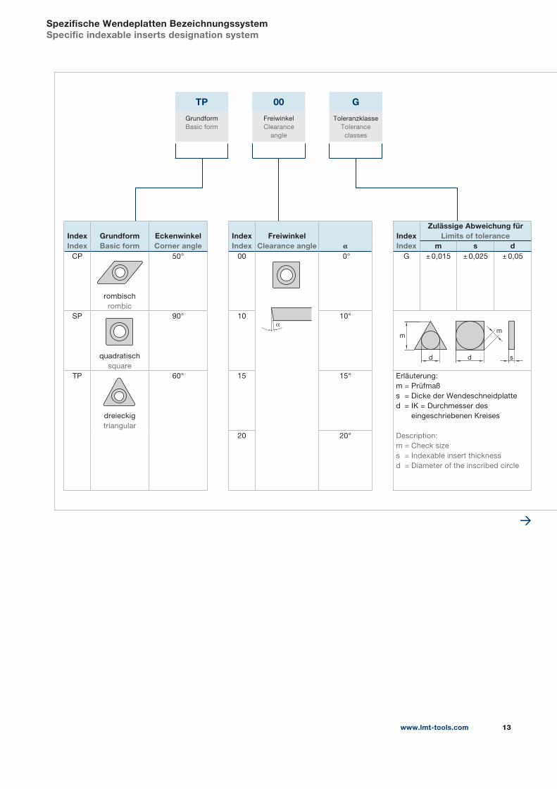
Spezifische Wendeplatten BezeichnungssystemSpecific indexable inserts designation system
TP 00 G
Grundform
Basic form
Freiwinkel
Clearance
angle
Toleranzklasse
Tolerance
classes
IndexIndex
GrundformBasic form
EckenwinkelCorner angle
IndexIndex
FreiwinkelClearance angle α
IndexIndex
Zulässige Abweichung für Limits of tolerance
m s dCP
rombisch
rombic
50° 00 0° G ± 0,015 ± 0,025 ± 0,05
SP
quadratisch
square
90° 10 10°
m
dd
m
s
TP
dreieckig
triangular
60° 15 15° Erläuterung:
m = Prüfmaß
s = Dicke der Wendeschneidplatte
d = IK = Durchmesser des
eingeschriebenen Kreises
Description:
m = Check size
s = Indexable insert thickness
d = Diameter of the inscribed circle
20 20°
α
www.lmt-tools.com 13
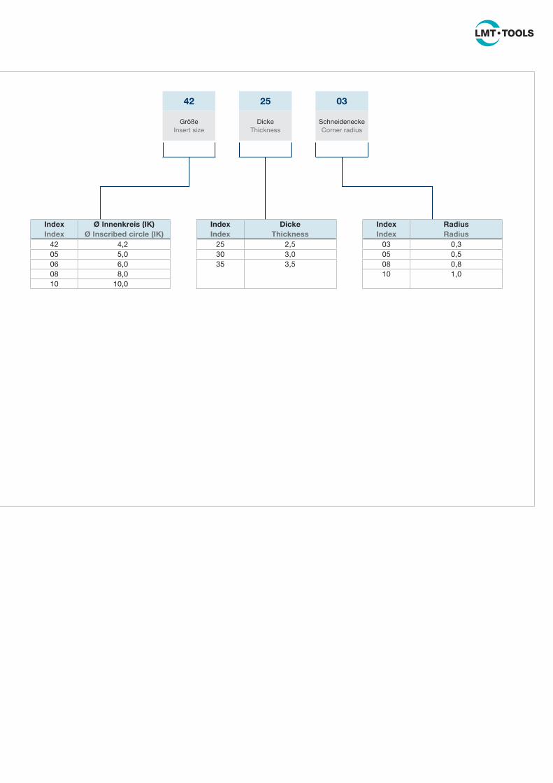
42 25 03
Größe
Insert size
Dicke
Thickness
Schneidenecke
Corner radius
IndexIndex
Ø Innenkreis (IK)Ø Inscribed circle (IK)
IndexIndex
DickeThickness
IndexIndex
RadiusRadius
42 4,2 25 2,5 03 0,3
05 5,0 30 3,0 05 0,5
06 6,0 35 3,5 08 0,8
08 8,0 10 1,0
10 10,0
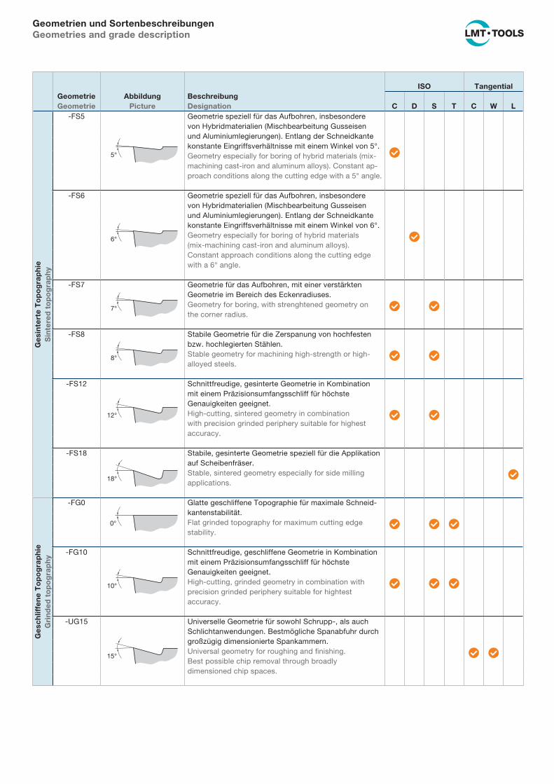
Geometrien und SortenbeschreibungenGeometries and grade description
GeometrieGeometrie
AbbildungPicture
BeschreibungDesignation
ISO Tangential
C D S T C W L
Ges
inte
rte
To
po
gra
ph
ieS
inte
red
to
po
gra
ph
y
-FS5
5°
Geometrie speziell für das Aufbohren, insbesondere
von Hybrid materialien (Mischbearbeitung Gusseisen
und Aluminiumlegierungen). Entlang der Schneidkante
konstante Eingriffs verhältnisse mit einem Winkel von 5°.
Geometry especially for boring of hybrid materials (mix-
machining cast-iron and aluminum alloys). Constant ap-
proach conditions along the cutting edge with a 5° angle.
�
-FS6
6°
Geometrie speziell für das Aufbohren, insbesondere
von Hybrid materialien (Mischbearbeitung Gusseisen
und Aluminiumlegierungen). Entlang der Schneidkante
konstante Eingriffs verhältnisse mit einem Winkel von 6°.
Geometry especially for boring of hybrid materials
(mix-machining cast-iron and aluminum alloys).
Constant approach conditions along the cutting edge
with a 6° angle.
�
-FS7
7°
Geometrie für das Aufbohren, mit einer verstärkten
Geometrie im Bereich des Eckenradiuses.
Geometry for boring, with strenghtened geometry on
the corner radius.� �
-FS8
8°
Stabile Geometrie für die Zerspanung von hochfesten
bzw. hoch legierten Stählen.
Stable geometry for machining high-strength or high-
alloyed steels.� �
-FS12
12°
Schnittfreudige, gesinterte Geometrie in Kombination
mit einem Präzisionsumfangsschliff für höchste
Genauigkeiten geeignet.
High-cutting, sintered geometry in combination
with precision grinded periphery suitable for highest
accuracy.
� �
-FS18
18°
Stabile, gesinterte Geometrie speziell für die Applikation
auf Scheiben fräser.
Stable, sintered geometry especially for side milling
applications.�
Ges
chlif
fen
e T
op
og
rap
hie
Gri
nd
ed t
op
og
rap
hy
-FG0
0°
Glatte geschliffene Topographie für maximale Schneid-
kantenstabilität.
Flat grinded topography for maximum cutting edge
stability.� � �
-FG10
10°
Schnittfreudige, geschliffene Geometrie in Kombination
mit einem Präzisionsumfangsschliff für höchste
Genauig keiten geeignet.
High-cutting, grinded geometry in combination with
precision grinded periphery suitable for hightest
accuracy.
� � �
-UG15
15°
Universelle Geometrie für sowohl Schrupp-, als auch
Schlichtanwendungen. Bestmögliche Spanabfuhr durch
großzügig dimensionierte Spankammern.
Universal geometry for roughing and finishing.
Best possible chip removal through broadly
dimensioned chip spaces.
� �
www.lmt-tools.com14
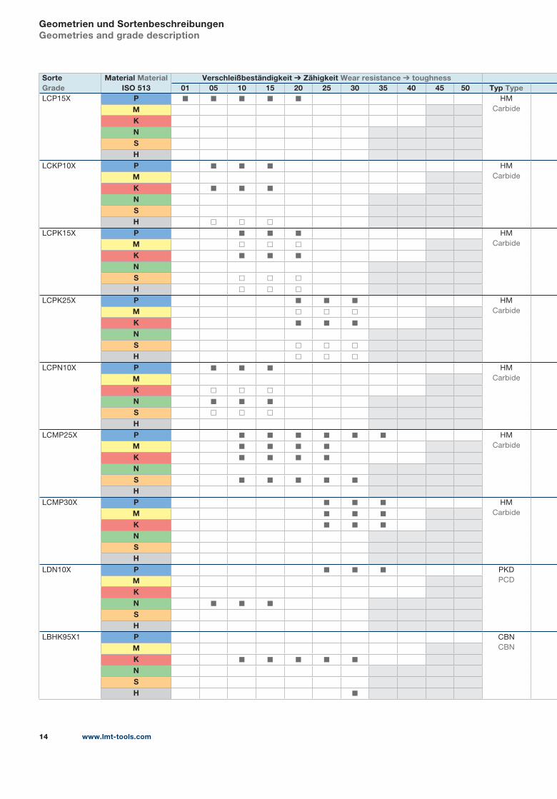
Geometrien und SortenbeschreibungenGeometries and grade description
SorteGrade
Material MaterialISO 513
Verschleißbeständigkeit Zähigkeit Wear resistance toughness01 05 10 15 20 25 30 35 40 45 50 Typ Type
LCP15X P ◼ ◼ ◼ ◼ ◼ HM
CarbideMKNSH
LCKP10X P ◼ ◼ ◼ HM
CarbideMK ◼ ◼ ◼NSH ◻ ◻ ◻
LCPK15X P ◼ ◼ ◼ HM
CarbideM ◻ ◻ ◻K ◼ ◼ ◼NS ◻ ◻ ◻H ◻ ◻ ◻
LCPK25X P ◼ ◼ ◼ HM
CarbideM ◻ ◻ ◻K ◼ ◼ ◼NS ◻ ◻ ◻H ◻ ◻ ◻
LCPN10X P ◼ ◼ ◼ HM
CarbideMK ◻ ◻ ◻N ◼ ◼ ◼S ◻ ◻ ◻H
LCMP25X P ◼ ◼ ◼ ◼ ◼ ◼ HM
CarbideM ◼ ◼ ◼ ◼K ◼ ◼ ◼ ◼NS ◼ ◼ ◼ ◼ ◼H
LCMP30X P ◼ ◼ ◼ HM
CarbideM ◼ ◼ ◼K ◼ ◼ ◼NSH
LDN10X P ◼ ◼ ◼ PKD
PCDMKN ◼ ◼ ◼SH
LBHK95X1 P CBN
CBNMK ◼ ◼ ◼ ◼ ◼NSH ◼
www.lmt-tools.com 15
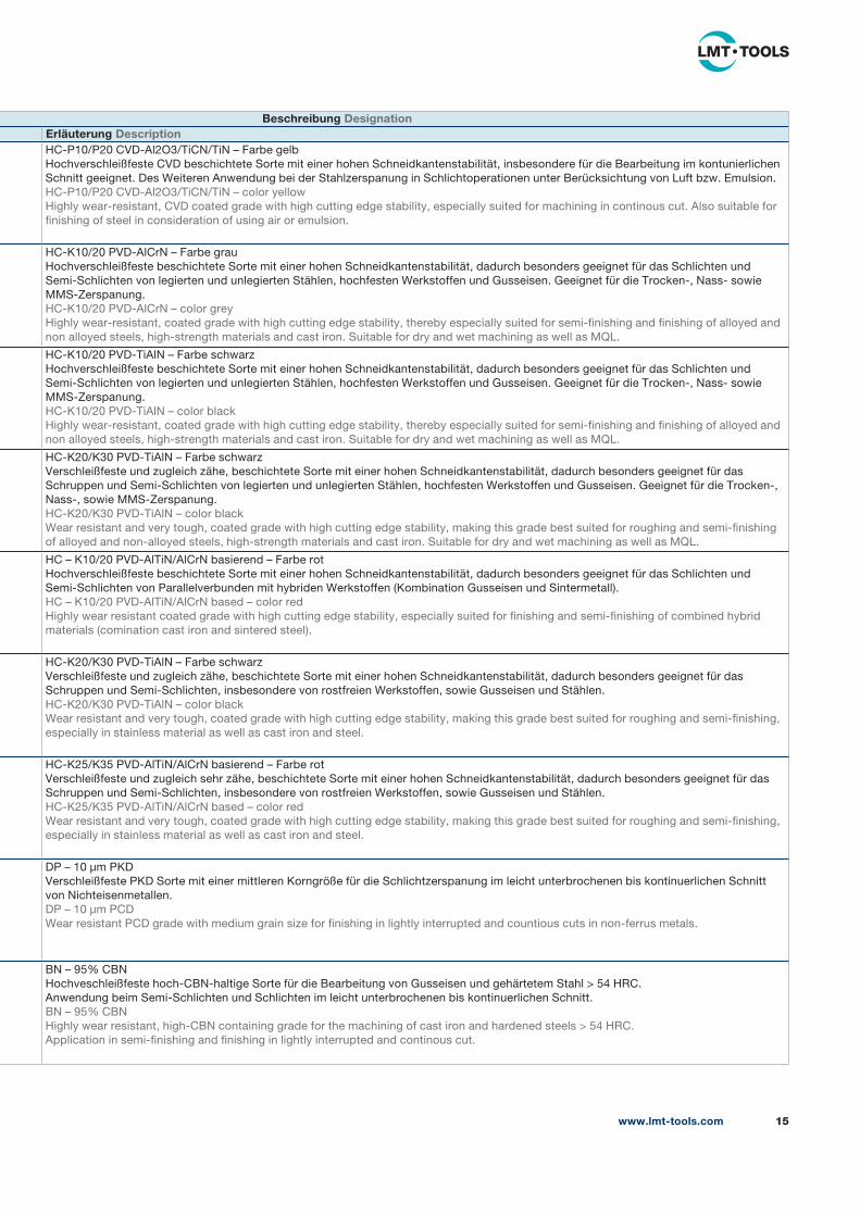
Beschreibung DesignationErläuterung DescriptionHC-P10/P20 CVD-Al2O3/TiCN/TiN – Farbe gelb
Hochverschleißfeste CVD beschichtete Sorte mit einer hohen Schneidkantenstabilität, insbesondere für die Bearbeitung im kontunierlichen
Schnitt geeignet. Des Weiteren Anwendung bei der Stahlzerspanung in Schlichtoperationen unter Berücksichtung von Luft bzw. Emulsion.
HC-P10/P20 CVD-Al2O3/TiCN/TiN – color yellow
Highly wear-resistant, CVD coated grade with high cutting edge stability, especially suited for machining in continous cut. Also suitable for
finishing of steel in consideration of using air or emulsion.
HC-K10/20 PVD-AlCrN – Farbe grau
Hochverschleißfeste beschichtete Sorte mit einer hohen Schneidkantenstabilität, dadurch besonders geeignet für das Schlichten und
Semi-Schlichten von legierten und unlegierten Stählen, hochfesten Werkstoffen und Gusseisen. Geeignet für die Trocken-, Nass- sowie
MMS-Zerspanung.
HC-K10/20 PVD-AlCrN – color grey
Highly wear-resistant, coated grade with high cutting edge stability, thereby especially suited for semi-finishing and finishing of alloyed and
non alloyed steels, high-strength materials and cast iron. Suitable for dry and wet machining as well as MQL.
HC-K10/20 PVD-TiAlN – Farbe schwarz
Hochverschleißfeste beschichtete Sorte mit einer hohen Schneidkantenstabilität, dadurch besonders geeignet für das Schlichten und
Semi-Schlichten von legierten und unlegierten Stählen, hochfesten Werkstoffen und Gusseisen. Geeignet für die Trocken-, Nass- sowie
MMS-Zerspanung.
HC-K10/20 PVD-TiAlN – color black
Highly wear-resistant, coated grade with high cutting edge stability, thereby especially suited for semi-finishing and finishing of alloyed and
non alloyed steels, high-strength materials and cast iron. Suitable for dry and wet machining as well as MQL.
HC-K20/K30 PVD-TiAlN – Farbe schwarz
Verschleißfeste und zugleich zähe, beschichtete Sorte mit einer hohen Schneidkantenstabilität, dadurch besonders geeignet für das
Schruppen und Semi-Schlichten von legierten und unlegierten Stählen, hochfesten Werkstoffen und Gusseisen. Geeignet für die Trocken-,
Nass-, sowie MMS-Zerspanung.
HC-K20/K30 PVD-TiAlN – color black
Wear resistant and very tough, coated grade with high cutting edge stability, making this grade best suited for roughing and semi-finishing
of alloyed and non-alloyed steels, high-strength materials and cast iron. Suitable for dry and wet machining as well as MQL.
HC – K10/20 PVD-AlTiN/AlCrN basierend – Farbe rot
Hochverschleißfeste beschichtete Sorte mit einer hohen Schneidkantenstabilität, dadurch besonders geeignet für das Schlichten und
Semi-Schlichten von Parallelverbunden mit hybriden Werkstoffen (Kombination Gusseisen und Sintermetall).
HC – K10/20 PVD-AlTiN/AlCrN based – color red
Highly wear resistant coated grade with high cutting edge stability, especially suited for finishing and semi-finishing of combined hybrid
materials (comination cast iron and sintered steel).
HC-K20/K30 PVD-TiAlN – Farbe schwarz
Verschleißfeste und zugleich zähe, beschichtete Sorte mit einer hohen Schneidkantenstabilität, dadurch besonders geeignet für das
Schruppen und Semi-Schlichten, insbesondere von rostfreien Werkstoffen, sowie Gusseisen und Stählen.
HC-K20/K30 PVD-TiAlN – color black
Wear resistant and very tough, coated grade with high cutting edge stability, making this grade best suited for roughing and semi-finishing,
especially in stainless material as well as cast iron and steel.
HC-K25/K35 PVD-AlTiN/AlCrN basierend – Farbe rot
Verschleißfeste und zugleich sehr zähe, beschichtete Sorte mit einer hohen Schneidkantenstabilität, dadurch besonders geeignet für das
Schruppen und Semi-Schlichten, insbesondere von rostfreien Werkstoffen, sowie Gusseisen und Stählen.
HC-K25/K35 PVD-AlTiN/AlCrN based – color red
Wear resistant and very tough, coated grade with high cutting edge stability, making this grade best suited for roughing and semi-finishing,
especially in stainless material as well as cast iron and steel.
DP – 10 μm PKD
Verschleißfeste PKD Sorte mit einer mittleren Korngröße für die Schlichtzerspanung im leicht unterbrochenen bis kontinuerlichen Schnitt
von Nichteisenmetallen.
DP – 10 μm PCD
Wear resistant PCD grade with medium grain size for finishing in lightly interrupted and countious cuts in non-ferrus metals.
BN – 95% CBN
Hochveschleißfeste hoch-CBN-haltige Sorte für die Bearbeitung von Gusseisen und gehärtetem Stahl > 54 HRC.
Anwendung beim Semi-Schlichten und Schlichten im leicht unterbrochenen bis kontinuerlichen Schnitt.
BN – 95% CBN
Highly wear resistant, high-CBN containing grade for the machining of cast iron and hardened steels > 54 HRC.
Application in semi-finishing and finishing in lightly interrupted and continous cut.
ISO WENDESCHNEIDPLATTEN
www.lmt-tools.com 17
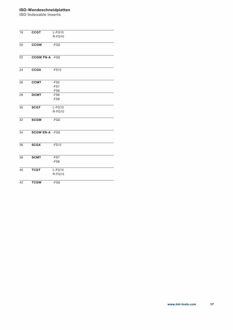
ISO-WendeschneidplattenISO Indexable inserts
18 CCGT L-FG10
R-FG10
20 CCGW -FG0
22 CCGW FN-A -FG0
24 CCGX -FS12
26 CCMT -FS5
-FS7
-FS8
28 DCMT -FS6
-FS8
30 SCGT L-FG10
R-FG10
32 SCGW -FG0
34 SCGW EN-A -FG0
36 SCGX -FS12
38 SCMT -FS7
-FS8
40 TCGT L-FG10
R-FG10
42 TCGW -FG0
◼ = Hauptanwendung First choice
◻ = Nebenanwendung Second choice
+
+
www.lmt-tools.com18
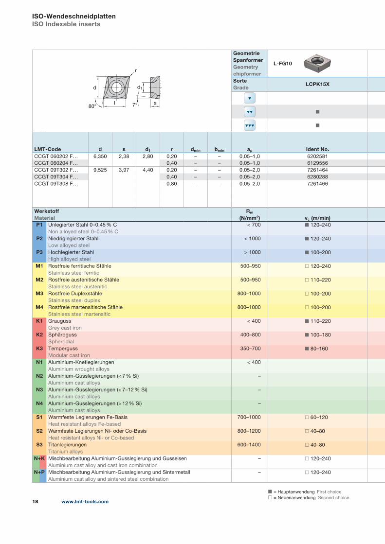
ISO-WendeschneidplattenISO Indexable inserts
r
d
l s80° 7°
d1
Geometrie SpanformerGeometrychipformer
L-FG10
SorteGrade
LCPK15X
◼
◼
LMT-Code d s d1 r dmin bmin ap Ident No.CCGT 060202 F… 6,350 2,38 2,80 0,20 – – 0,05–1,0 6202581
CCGT 060204 F… 0,40 – – 0,05–1,0 6129556
CCGT 09T302 F… 9,525 3,97 4,40 0,20 – – 0,05–2,0 7261464
CCGT 09T304 F… 0,40 – – 0,05–2,0 6280288
CCGT 09T308 F… 0,80 – – 0,05–2,0 7261466
WerkstoffMaterial
Rm
(N/mm2) vc (m/min)P1 Unlegierter Stahl 0–0,45 % C
Non alloyed steel 0–0.45 % C
< 700 ◼ 120–240
P2 Niedriglegierter Stahl
Low alloyed steel
< 1000 ◼ 120–240
P3 Hochlegierter Stahl
High alloyed steel
> 1000 ◼ 100–200
M1 Rostfreie ferritische Stähle
Stainless steel ferritic
500–950 ◻ 120–240
M2 Rostfreie austenitische Stähle
Stainless steel austenitic
500–950 ◻ 110–220
M3 Rostfreie Duplexstähle
Stainless steel duplex
800–1000 ◻ 100–200
M4 Rostfreie martensitische Stähle
Stainless steel martensitic
800–1000 ◻ 100–200
K1 Grauguss
Grey cast iron
< 400 ◼ 110–220
K2 Sphäroguss
Spherodial
400–800 ◼ 100–180
K3 Temperguss
Modular cast iron
350–700 ◼ 80–160
N1 Aluminium-Knetlegierungen
Aluminium wrought alloys
< 400
N2 Aluminium-Gusslegierungen (< 7 % Si)
Aluminium cast alloys
–
N3 Aluminium-Gusslegierungen (< 7–12 % Si)
Aluminium cast alloys
–
N4 Aluminium-Gusslegierungen (> 12 % Si)
Aluminium cast alloys
–
S1 Warmfeste Legierungen Fe-Basis
Heat resistant alloys Fe-based
700–1000 ◻ 60–120
S2 Warmfeste Legierungen Ni- oder Co-Basis
Heat resistant alloys Ni- or Co-based
800–1200 ◻ 40–80
S3 Titanlegierungen
Titanium alloys
600–1400 ◻ 40–80
N K Mischbearbeitung Aluminium-Gusslegierung und Gusseisen
Aluminium cast alloy and cast iron combination
– ◻ 120–240
N P Mischbearbeitung Aluminium-Gusslegierung und Sintermetall
Aluminium cast alloy and sintered steel combination
– ◻ 120–240
+
+
1) Wert fz abhängig von Spanformer Geometrie (siehe Vorschubempfehlungen unten)
fz figure depending on chip breaker geometry (see feed recommendations below)
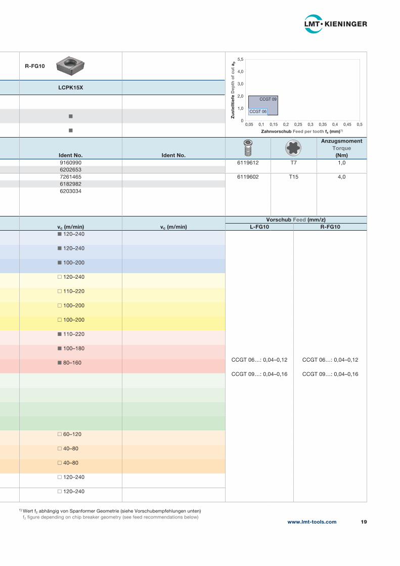
R-FG10
LCPK15X
◼
◼
Ident No. Ident No.
AnzugsmomentTorque
(Nm)9160990 6119612 T7 1,0
6202653
7261465 6119602 T15 4,0
6182982
6203034
vc (m/min) vc (m/min)Vorschub Feed (mm/z)
L-FG10 R-FG10◼ 120–240
CCGT 06…: 0,04–0,12
CCGT 09…: 0,04–0,16
CCGT 06…: 0,04–0,12
CCGT 09…: 0,04–0,16
◼ 120–240
◼ 100–200
◻ 120–240
◻ 110–220
◻ 100–200
◻ 100–200
◼ 110–220
◼ 100–180
◼ 80–160
◻ 60–120
◻ 40–80
◻ 40–80
◻ 120–240
◻ 120–240
www.lmt-tools.com 19
5,5
4,0
3,0
2,0
1,0
00,05 0,1 0,15 0,2 0,25 0,3 0,35 0,4 0,45 0,5
Zahnvorschub Feed per tooth fz (mm)1)
Zu
stel
ltie
fe D
epth
of
cut
a p
CCGT 06
CCGT 09

◼ = Hauptanwendung First choice
◻ = Nebenanwendung Second choice
+
+
www.lmt-tools.com20
r
d
l s80° 7°
d1
Geometrie SpanformerGeometrychipformer
-FG0
SorteGrade
LCPK15X
◻
◻
◼
LMT-Code d s d1 r dmin bmin ap Ident No.CCGW 060202 FN 6,350 2,38 2,80 0,20 – – 0,1–1,0 6203564
CCGW 060204 FN 0,40 – – 0,1–1,0 6200514
CCGW 060208 FN 0,80 – – 0,1–1,0 6182715
CCGW 09T302 FN 9,525 3,97 4,40 0,20 – – 0,1–2,0 7261445
CCGW 09T304 FN 0,40 – – 0,1–2,0 6182489
CCGW 09T308 FN 0,80 – – 0,1–2,0 6161306
CCGW 120404 FN 12,700 4,76 5,50 0,40 – – 0,1–3,0 6183121
CCGW 120408 FN 0,80 – – 0,1–3,0 6201825
WerkstoffMaterial
Rm
(N/mm2) vc (m/min)P1 Unlegierter Stahl 0–0,45 % C
Non alloyed steel 0–0.45 % C
< 700 ◼ 120–240
P2 Niedriglegierter Stahl
Low alloyed steel
< 1000 ◼ 120–240
P3 Hochlegierter Stahl
High alloyed steel
> 1000 ◼ 100–200
M1 Rostfreie ferritische Stähle
Stainless steel ferritic
500–950 ◻ 120–240
M2 Rostfreie austenitische Stähle
Stainless steel austenitic
500–950 ◻ 110–220
M3 Rostfreie Duplexstähle
Stainless steel duplex
800–1000 ◻ 100–200
M4 Rostfreie martensitische Stähle
Stainless steel martensitic
800–1000 ◻ 100–200
K1 Grauguss
Grey cast iron
< 400 ◼ 110–220
K2 Sphäroguss
Spherodial
400–800 ◼ 100–180
K3 Temperguss
Modular cast iron
350–700 ◼ 80–160
N1 Aluminium-Knetlegierungen
Aluminium wrought alloys
< 400
N2 Aluminium-Gusslegierungen (< 7 % Si)
Aluminium cast alloys
–
N3 Aluminium-Gusslegierungen (< 7–12 % Si)
Aluminium cast alloys
–
N4 Aluminium-Gusslegierungen (> 12 % Si)
Aluminium cast alloys
–
S1 Warmfeste Legierungen Fe-Basis
Heat resistant alloys Fe-based
700–1000 ◻ 60–120
S2 Warmfeste Legierungen Ni- oder Co-Basis
Heat resistant alloys Ni- or Co-based
800–1200 ◻ 40–80
S3 Titanlegierungen
Titanium alloys
600–1400 ◻ 40–80
N K Mischbearbeitung Aluminium-Gusslegierung und Gusseisen
Aluminium cast alloy and cast iron combination
– ◻ 120–240
N P Mischbearbeitung Aluminium-Gusslegierung und Sintermetall
Aluminium cast alloy and sintered steel combination
– ◻ 120–240
ISO-WendeschneidplattenISO Indexable inserts
+
+
1) Wert fz abhängig von Spanformer Geometrie (siehe Vorschubempfehlungen unten)
fz figure depending on chip breaker geometry (see feed recommendations below)
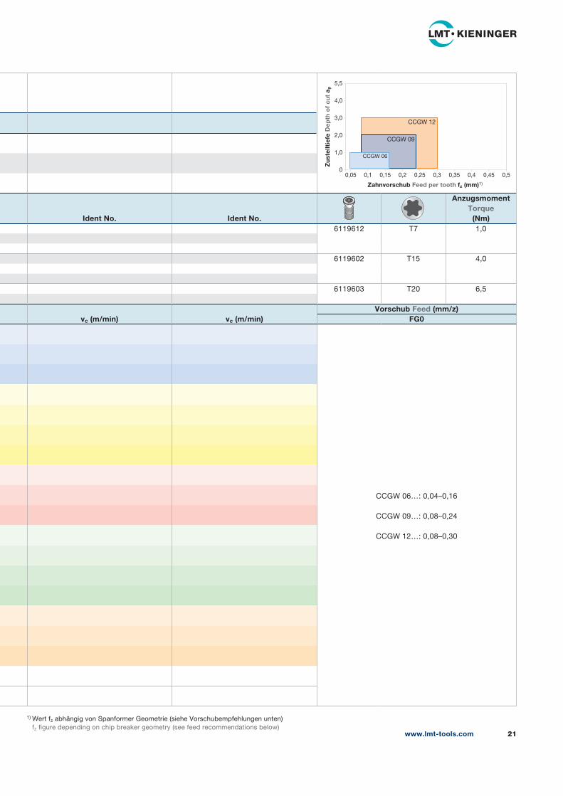
Ident No. Ident No.
AnzugsmomentTorque
(Nm)6119612 T7 1,0
6119602 T15 4,0
6119603 T20 6,5
vc (m/min) vc (m/min)Vorschub Feed (mm/z)
FG0
CCGW 06…: 0,04–0,16
CCGW 09…: 0,08–0,24
CCGW 12…: 0,08–0,30
www.lmt-tools.com 21
5,5
4,0
3,0
2,0
1,0
00,05 0,1 0,15 0,2 0,25 0,3 0,35 0,4 0,45 0,5
Zahnvorschub Feed per tooth fz (mm)1)
Zu
stel
ltie
fe D
epth
of
cut
a p
CCGW 06
CCGW 12
CCGW 09
◼ = Hauptanwendung First choice
◻ = Nebenanwendung Second choice
+
+
www.lmt-tools.com22
ISO-WendeschneidplattenISO Indexable inserts
r
d
lB
l
s80° 7°
d1
Geometrie SpanformerGeometrychipformer
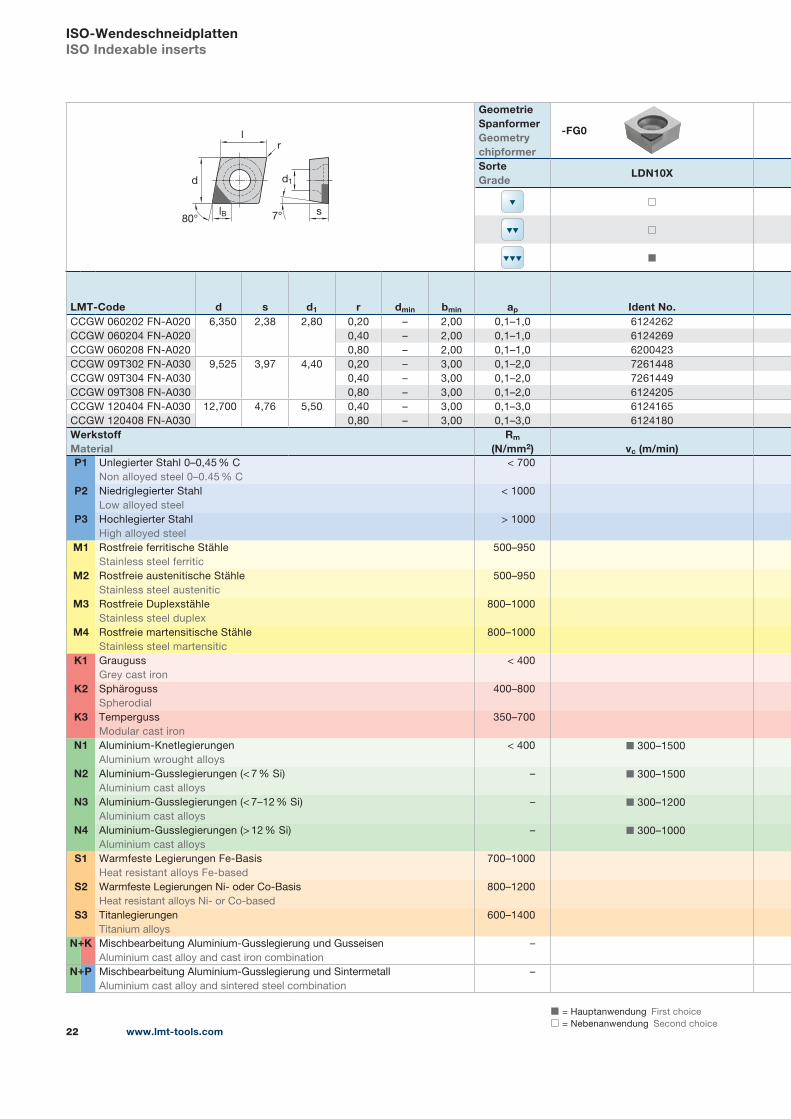
-FG0
SorteGrade
LDN10X
◻
◻
◼
LMT-Code d s d1 r dmin bmin ap Ident No.CCGW 060202 FN-A020 6,350 2,38 2,80 0,20 – 2,00 0,1–1,0 6124262
CCGW 060204 FN-A020 0,40 – 2,00 0,1–1,0 6124269
CCGW 060208 FN-A020 0,80 – 2,00 0,1–1,0 6200423
CCGW 09T302 FN-A030 9,525 3,97 4,40 0,20 – 3,00 0,1–2,0 7261448
CCGW 09T304 FN-A030 0,40 – 3,00 0,1–2,0 7261449
CCGW 09T308 FN-A030 0,80 – 3,00 0,1–2,0 6124205
CCGW 120404 FN-A030 12,700 4,76 5,50 0,40 – 3,00 0,1–3,0 6124165
CCGW 120408 FN-A030 0,80 – 3,00 0,1–3,0 6124180
WerkstoffMaterial
Rm
(N/mm2) vc (m/min)P1 Unlegierter Stahl 0–0,45 % C
Non alloyed steel 0–0.45 % C
< 700
P2 Niedriglegierter Stahl
Low alloyed steel
< 1000
P3 Hochlegierter Stahl
High alloyed steel
> 1000
M1 Rostfreie ferritische Stähle
Stainless steel ferritic
500–950
M2 Rostfreie austenitische Stähle
Stainless steel austenitic
500–950
M3 Rostfreie Duplexstähle
Stainless steel duplex
800–1000
M4 Rostfreie martensitische Stähle
Stainless steel martensitic
800–1000
K1 Grauguss
Grey cast iron
< 400
K2 Sphäroguss
Spherodial
400–800
K3 Temperguss
Modular cast iron
350–700
N1 Aluminium-Knetlegierungen
Aluminium wrought alloys
< 400 ◼ 300–1500
N2 Aluminium-Gusslegierungen (< 7 % Si)
Aluminium cast alloys
– ◼ 300–1500
N3 Aluminium-Gusslegierungen (< 7–12 % Si)
Aluminium cast alloys
– ◼ 300–1200
N4 Aluminium-Gusslegierungen (> 12 % Si)
Aluminium cast alloys
– ◼ 300–1000
S1 Warmfeste Legierungen Fe-Basis
Heat resistant alloys Fe-based
700–1000
S2 Warmfeste Legierungen Ni- oder Co-Basis
Heat resistant alloys Ni- or Co-based
800–1200
S3 Titanlegierungen
Titanium alloys
600–1400
N K Mischbearbeitung Aluminium-Gusslegierung und Gusseisen
Aluminium cast alloy and cast iron combination
–
N P Mischbearbeitung Aluminium-Gusslegierung und Sintermetall
Aluminium cast alloy and sintered steel combination
–
+
+

1) Wert fz abhängig von Spanformer Geometrie (siehe Vorschubempfehlungen unten)
fz figure depending on chip breaker geometry (see feed recommendations below)
Ident No. Ident No.
AnzugsmomentTorque
(Nm)6119612 T7 1,0
6119602 T15 4,0
6119603 T20 6,5
vc (m/min) vc (m/min)Vorschub Feed (mm/z)
FG0
CCGW 06…: 0,04–0,16
CCGW 09…: 0,08–0,24
CCGW 12…: 0,08–0,30
www.lmt-tools.com 23
5,5
4,0
3,0
2,0
1,0
00,05 0,1 0,15 0,2 0,25 0,3 0,35 0,4 0,45 0,5
Zahnvorschub Feed per tooth fz (mm)1)
Zu
stel
ltie
fe D
epth
of
cut
a p
CCGW FN-A 06
CCGW FN-A 12
CCGW FN-A 09
◼ = Hauptanwendung First choice
◻ = Nebenanwendung Second choice
+
+
www.lmt-tools.com24
ISO-WendeschneidplattenISO Indexable inserts
s7°
d1
r
d
l80°
Geometrie SpanformerGeometrychipformer
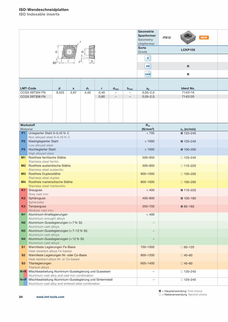
-FS12
SorteGrade
LCKP10X
◼
◼
LMT-Code d s d1 r dmin bmin ap Ident No.CCGX 09T304 FN 9,525 3,97 4,40 0,40 – – 0,05–2,0 7143119
CCGX 09T308 FN 0,80 – – 0,05–2,0 7143120
WerkstoffMaterial
Rm
(N/mm2) vc (m/min)P1 Unlegierter Stahl 0–0,45 % C
Non alloyed steel 0–0.45 % C
< 700 ◼ 120–240
P2 Niedriglegierter Stahl
Low alloyed steel
< 1000 ◼ 120–240
P3 Hochlegierter Stahl
High alloyed steel
> 1000 ◼ 100–200
M1 Rostfreie ferritische Stähle
Stainless steel ferritic
500–950 ◻ 120–240
M2 Rostfreie austenitische Stähle
Stainless steel austenitic
500–950 ◻ 110–220
M3 Rostfreie Duplexstähle
Stainless steel duplex
800–1000 ◻ 100–200
M4 Rostfreie martensitische Stähle
Stainless steel martensitic
800–1000 ◻ 100–200
K1 Grauguss
Grey cast iron
< 400 ◼ 110–220
K2 Sphäroguss
Spherodial
400–800 ◼ 100–180
K3 Temperguss
Modular cast iron
350–700 ◼ 80–160
N1 Aluminium-Knetlegierungen
Aluminium wrought alloys
< 400
N2 Aluminium-Gusslegierungen (< 7 % Si)
Aluminium cast alloys
–
N3 Aluminium-Gusslegierungen (< 7–12 % Si)
Aluminium cast alloys
–
N4 Aluminium-Gusslegierungen (> 12 % Si)
Aluminium cast alloys
–
S1 Warmfeste Legierungen Fe-Basis
Heat resistant alloys Fe-based
700–1000 ◻ 60–120
S2 Warmfeste Legierungen Ni- oder Co-Basis
Heat resistant alloys Ni- or Co-based
800–1200 ◻ 40–80
S3 Titanlegierungen
Titanium alloys
600–1400 ◻ 40–80
N K Mischbearbeitung Aluminium-Gusslegierung und Gusseisen
Aluminium cast alloy and cast iron combination
– ◻ 120–240
N P Mischbearbeitung Aluminium-Gusslegierung und Sintermetall
Aluminium cast alloy and sintered steel combination
– ◻ 120–240
+
+

1) Wert fz abhängig von Spanformer Geometrie (siehe Vorschubempfehlungen unten)
fz figure depending on chip breaker geometry (see feed recommendations below)
-FS12 -FS12
LCPK15X LCPN10X
◼ ◼
◼ ◼
Ident No. Ident No.
AnzugsmomentTorque
(Nm)7143129 7315249 6119602 T15 4,0
7143130 7315250
vc (m/min) vc (m/min)Vorschub Feed (mm/z)
FS12◼ 120–240 ◼ 120–240
CCGX 09…: 0,04–0,16
◼ 120–240 ◼ 120–240
◼ 100–200 ◼ 100–200
◻ 120–240 ◻ 120–240
◻ 110–220 ◻ 110–220
◻ 100–200 ◻ 100–200
◻ 100–200 ◻ 100–200
◼ 110–220 ◼ 110–220
◼ 100–180 ◼ 100–180
◼ 80–160 ◼ 80–160
◻ 60–120 ◻ 60–120
◻ 40–80 ◻ 40–80
◻ 40–80 ◻ 40–80
◻ 120–240 ◻ 120–240
◻ 120–240 ◻ 120–240
www.lmt-tools.com 25
5,5
4,0
3,0
2,0
1,0
00,05 0,1 0,15 0,2 0,25 0,3 0,35 0,4 0,45 0,5
Zahnvorschub Feed per tooth fz (mm)1)
Zu
stel
ltie
fe D
epth
of
cut
a p
CCGX 09
www.lmt-tools.com26
◼ = Hauptanwendung First choice
◻ = Nebenanwendung Second choice
+
+
ISO-WendeschneidplattenISO Indexable inserts
7°
d1
s
r
d
l80°
Geometrie SpanformerGeometrychipformer
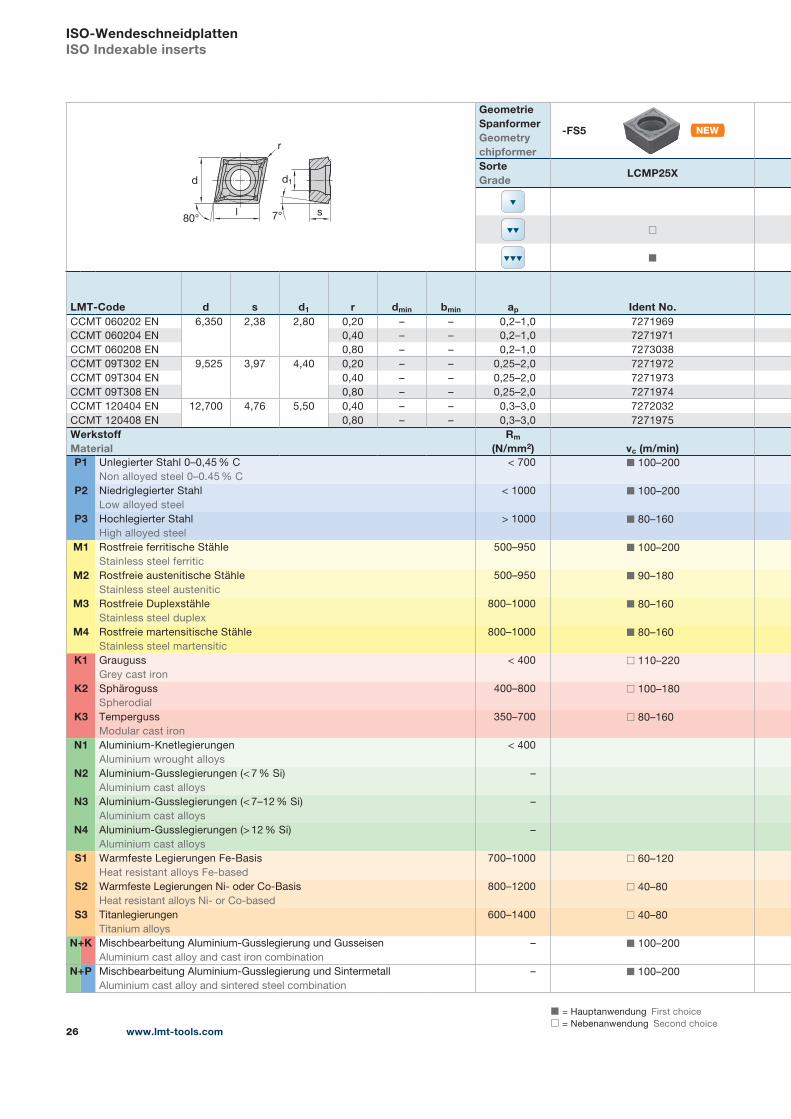
-FS5
SorteGrade
LCMP25X
◻
◼
LMT-Code d s d1 r dmin bmin ap Ident No.CCMT 060202 EN 6,350 2,38 2,80 0,20 – – 0,2–1,0 7271969
CCMT 060204 EN 0,40 – – 0,2–1,0 7271971
CCMT 060208 EN 0,80 – – 0,2–1,0 7273038
CCMT 09T302 EN 9,525 3,97 4,40 0,20 – – 0,25–2,0 7271972
CCMT 09T304 EN 0,40 – – 0,25–2,0 7271973
CCMT 09T308 EN 0,80 – – 0,25–2,0 7271974
CCMT 120404 EN 12,700 4,76 5,50 0,40 – – 0,3–3,0 7272032
CCMT 120408 EN 0,80 – – 0,3–3,0 7271975
WerkstoffMaterial
Rm
(N/mm2) vc (m/min)P1 Unlegierter Stahl 0–0,45 % C
Non alloyed steel 0–0.45 % C
< 700 ◼ 100–200
P2 Niedriglegierter Stahl
Low alloyed steel
< 1000 ◼ 100–200
P3 Hochlegierter Stahl
High alloyed steel
> 1000 ◼ 80–160
M1 Rostfreie ferritische Stähle
Stainless steel ferritic
500–950 ◼ 100–200
M2 Rostfreie austenitische Stähle
Stainless steel austenitic
500–950 ◼ 90–180
M3 Rostfreie Duplexstähle
Stainless steel duplex
800–1000 ◼ 80–160
M4 Rostfreie martensitische Stähle
Stainless steel martensitic
800–1000 ◼ 80–160
K1 Grauguss
Grey cast iron
< 400 ◻ 110–220
K2 Sphäroguss
Spherodial
400–800 ◻ 100–180
K3 Temperguss
Modular cast iron
350–700 ◻ 80–160
N1 Aluminium-Knetlegierungen
Aluminium wrought alloys
< 400
N2 Aluminium-Gusslegierungen (< 7 % Si)
Aluminium cast alloys
–
N3 Aluminium-Gusslegierungen (< 7–12 % Si)
Aluminium cast alloys
–
N4 Aluminium-Gusslegierungen (> 12 % Si)
Aluminium cast alloys
–
S1 Warmfeste Legierungen Fe-Basis
Heat resistant alloys Fe-based
700–1000 ◻ 60–120
S2 Warmfeste Legierungen Ni- oder Co-Basis
Heat resistant alloys Ni- or Co-based
800–1200 ◻ 40–80
S3 Titanlegierungen
Titanium alloys
600–1400 ◻ 40–80
N K Mischbearbeitung Aluminium-Gusslegierung und Gusseisen
Aluminium cast alloy and cast iron combination
– ◼ 100–200
N P Mischbearbeitung Aluminium-Gusslegierung und Sintermetall
Aluminium cast alloy and sintered steel combination
– ◼ 100–200
+
+
www.lmt-tools.com 27
1) Wert fz abhängig von Spanformer Geometrie (siehe Vorschubempfehlungen unten)
fz figure depending on chip breaker geometry (see feed recommendations below)
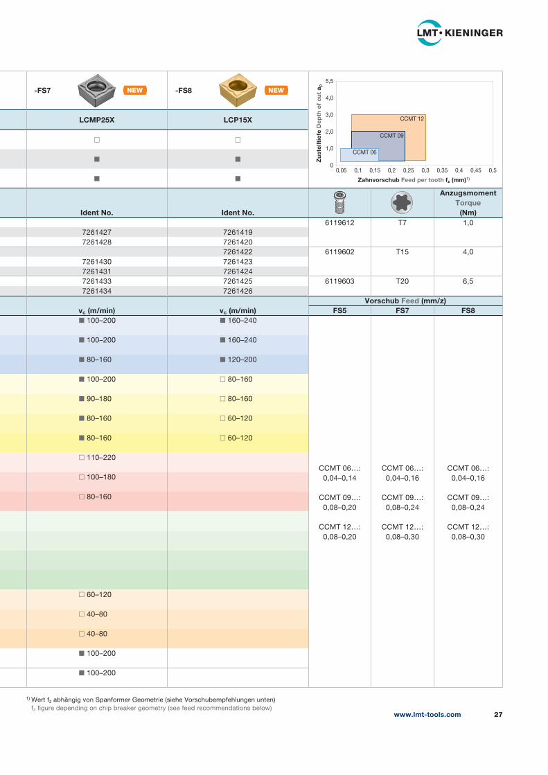
-FS7 -FS8
LCMP25X LCP15X
◻ ◻
◼ ◼
◼ ◼
Ident No. Ident No.
AnzugsmomentTorque
(Nm)6119612 T7 1,0
7261427 7261419
7261428 7261420
7261422 6119602 T15 4,0
7261430 7261423
7261431 7261424
7261433 7261425 6119603 T20 6,5
7261434 7261426
vc (m/min) vc (m/min)Vorschub Feed (mm/z)
FS5 FS7 FS8◼ 100–200 ◼ 160–240
CCMT 06…:
0,04–0,14
CCMT 09…:
0,08–0,20
CCMT 12…:
0,08–0,20
CCMT 06…:
0,04–0,16
CCMT 09…:
0,08–0,24
CCMT 12…:
0,08–0,30
CCMT 06…:
0,04–0,16
CCMT 09…:
0,08–0,24
CCMT 12…:
0,08–0,30
◼ 100–200 ◼ 160–240
◼ 80–160 ◼ 120–200
◼ 100–200 ◻ 80–160
◼ 90–180 ◻ 80–160
◼ 80–160 ◻ 60–120
◼ 80–160 ◻ 60–120
◻ 110–220
◻ 100–180
◻ 80–160
◻ 60–120
◻ 40–80
◻ 40–80
◼ 100–200
◼ 100–200
5,5
4,0
3,0
2,0
1,0
00,05 0,1 0,15 0,2 0,25 0,3 0,35 0,4 0,45 0,5
Zahnvorschub Feed per tooth fz (mm)1)
Zu
stel
ltie
fe D
epth
of
cut
a p
CCMT 06
CCMT 12
CCMT 09

◼ = Hauptanwendung First choice
◻ = Nebenanwendung Second choice
+
+
www.lmt-tools.com28
ISO-WendeschneidplattenISO Indexable inserts
r
d
l s55° 7°
d1
Geometrie SpanformerGeometrychipformer
-FS6
SorteGrade
LCMP25X
◻
◼
LMT-Code d s d1 r dmin bmin ap Ident No.DCMT 070202 EN 6,350 2,38 2,80 0,20 – – 0,2–1,0 7261518
DCMT 070204 EN 0,40 – – 0,2–1,0 7261519
DCMT 11T302 EN 9,525 3,97 4,40 0,20 – – 0,25–2,0 7261520
DCMT 11T304 EN 0,40 – – 0,25–2,0 7261521
DCMT 11T308 EN 0,80 – – 0,25–2,0 7261522
WerkstoffMaterial
Rm
(N/mm2) vc (m/min)P1 Unlegierter Stahl 0–0,45 % C
Non alloyed steel 0–0.45 % C
< 700 ◼ 100–200
P2 Niedriglegierter Stahl
Low alloyed steel
< 1000 ◼ 100–200
P3 Hochlegierter Stahl
High alloyed steel
> 1000 ◼ 80–160
M1 Rostfreie ferritische Stähle
Stainless steel ferritic
500–950 ◼ 100–200
M2 Rostfreie austenitische Stähle
Stainless steel austenitic
500–950 ◼ 90–180
M3 Rostfreie Duplexstähle
Stainless steel duplex
800–1000 ◼ 80–160
M4 Rostfreie martensitische Stähle
Stainless steel martensitic
800–1000 ◼ 80–160
K1 Grauguss
Grey cast iron
< 400 ◻ 110–220
K2 Sphäroguss
Spherodial
400–800 ◻ 100–180
K3 Temperguss
Modular cast iron
350–700 ◻ 80–160
N1 Aluminium-Knetlegierungen
Aluminium wrought alloys
< 400
N2 Aluminium-Gusslegierungen (< 7 % Si)
Aluminium cast alloys
–
N3 Aluminium-Gusslegierungen (< 7–12 % Si)
Aluminium cast alloys
–
N4 Aluminium-Gusslegierungen (> 12 % Si)
Aluminium cast alloys
–
S1 Warmfeste Legierungen Fe-Basis
Heat resistant alloys Fe-based
700–1000 ◻ 60–120
S2 Warmfeste Legierungen Ni- oder Co-Basis
Heat resistant alloys Ni- or Co-based
800–1200 ◻ 40–80
S3 Titanlegierungen
Titanium alloys
600–1400 ◻ 40–80
N K Mischbearbeitung Aluminium-Gusslegierung und Gusseisen
Aluminium cast alloy and cast iron combination
– ◼ 100–200
N P Mischbearbeitung Aluminium-Gusslegierung und Sintermetall
Aluminium cast alloy and sintered steel combination
– ◼ 100–200
+
+
1) Wert fz abhängig von Spanformer Geometrie (siehe Vorschubempfehlungen unten)
fz figure depending on chip breaker geometry (see feed recommendations below)
-FS8
LCP15X
◻
◼
◼
Ident No. Ident No.
AnzugsmomentTorque
(Nm)7261512 6119612 T7 1,0
7261513
7261514 6119602 T15 4,0
7261515
7261516
vc (m/min) vc (m/min)Vorschub Feed (mm/z)
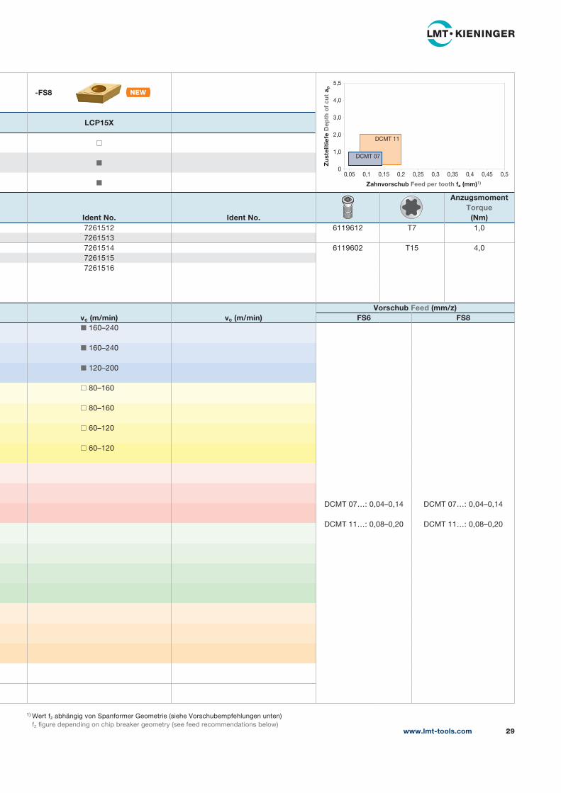
FS6 FS8◼ 160–240
DCMT 07…: 0,04–0,14
DCMT 11…: 0,08–0,20
DCMT 07…: 0,04–0,14
DCMT 11…: 0,08–0,20
◼ 160–240
◼ 120–200
◻ 80–160
◻ 80–160
◻ 60–120
◻ 60–120
www.lmt-tools.com 29
5,5
4,0
3,0
2,0
1,0
00,05 0,1 0,15 0,2 0,25 0,3 0,35 0,4 0,45 0,5
Zahnvorschub Feed per tooth fz (mm)1)
Zu
stel
ltie
fe D
epth
of
cut
a p
DCMT 07
DCMT 11

◼ = Hauptanwendung First choice
◻ = Nebenanwendung Second choice
+
+
www.lmt-tools.com30
ISO-WendeschneidplattenISO Indexable inserts
s7°
d1
r
l
d
90°
Geometrie SpanformerGeometrychipformer
L-FG10
SorteGrade
LCPK15X
◼
◼
LMT-Code d s d1 r dmin bmin ap Ident No.SCGT 060202 F… 6,350 2,38 2,80 0,20 – – 0,05–1,0 7261504
SCGT 060204 F… 0,40 – – 0,05–1,0 9158368
SCGT 09T304 F… 9,525 3,97 4,40 0,40 – – 0,05–2,0 6204053
SCGT 09T308 F… 0,80 – – 0,05–2,0 6203793
WerkstoffMaterial
Rm
(N/mm2) vc (m/min)P1 Unlegierter Stahl 0–0,45 % C
Non alloyed steel 0–0.45 % C
< 700 ◼ 120–240
P2 Niedriglegierter Stahl
Low alloyed steel
< 1000 ◼ 120–240
P3 Hochlegierter Stahl
High alloyed steel
> 1000 ◼ 100–200
M1 Rostfreie ferritische Stähle
Stainless steel ferritic
500–950 ◻ 120–240
M2 Rostfreie austenitische Stähle
Stainless steel austenitic
500–950 ◻ 110–220
M3 Rostfreie Duplexstähle
Stainless steel duplex
800–1000 ◻ 100–200
M4 Rostfreie martensitische Stähle
Stainless steel martensitic
800–1000 ◻ 100–200
K1 Grauguss
Grey cast iron
< 400 ◼ 110–220
K2 Sphäroguss
Spherodial
400–800 ◼ 100–180
K3 Temperguss
Modular cast iron
350–700 ◼ 80–160
N1 Aluminium-Knetlegierungen
Aluminium wrought alloys
< 400
N2 Aluminium-Gusslegierungen (< 7 % Si)
Aluminium cast alloys
–
N3 Aluminium-Gusslegierungen (< 7–12 % Si)
Aluminium cast alloys
–
N4 Aluminium-Gusslegierungen (> 12 % Si)
Aluminium cast alloys
–
S1 Warmfeste Legierungen Fe-Basis
Heat resistant alloys Fe-based
700–1000 ◻ 60–120
S2 Warmfeste Legierungen Ni- oder Co-Basis
Heat resistant alloys Ni- or Co-based
800–1200 ◻ 40–80
S3 Titanlegierungen
Titanium alloys
600–1400 ◻ 40–80
N K Mischbearbeitung Aluminium-Gusslegierung und Gusseisen
Aluminium cast alloy and cast iron combination
– ◻ 120–240
N P Mischbearbeitung Aluminium-Gusslegierung und Sintermetall
Aluminium cast alloy and sintered steel combination
– ◻ 120–240
+
+
1) Wert fz abhängig von Spanformer Geometrie (siehe Vorschubempfehlungen unten)
fz figure depending on chip breaker geometry (see feed recommendations below)
R-FG10
LCPK15X
◼
◼
Ident No. Ident No.
AnzugsmomentTorque
(Nm)7261505 6119612 T7 1,0
7261506
9137667 6119602 T15 4,0
9137668
vc (m/min) vc (m/min)Vorschub Feed (mm/z)
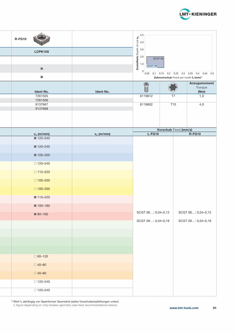
L-FG10 R-FG10◼ 120–240
SCGT 06…: 0,04–0,12
SCGT 09…: 0,04–0,16
SCGT 06…: 0,04–0,12
SCGT 09…: 0,04–0,16
◼ 120–240
◼ 100–200
◻ 120–240
◻ 110–220
◻ 100–200
◻ 100–200
◼ 110–220
◼ 100–180
◼ 80–160
◻ 60–120
◻ 40–80
◻ 40–80
◻ 120–240
◻ 120–240
www.lmt-tools.com 31
5,5
4,0
3,0
2,0
1,0
00,05 0,1 0,15 0,2 0,25 0,3 0,35 0,4 0,45 0,5
Zahnvorschub Feed per tooth fz (mm)1)
Zu
stel
ltie
fe D
epth
of
cut
a p
SCGT 06
SCGT 09
◼ = Hauptanwendung First choice
◻ = Nebenanwendung Second choice
+
+
www.lmt-tools.com32
ISO-WendeschneidplattenISO Indexable inserts
s7°
d1
r
l
d
90°
Geometrie SpanformerGeometrychipformer
-FG0
SorteGrade
LCPK15X
◻
◻
◼
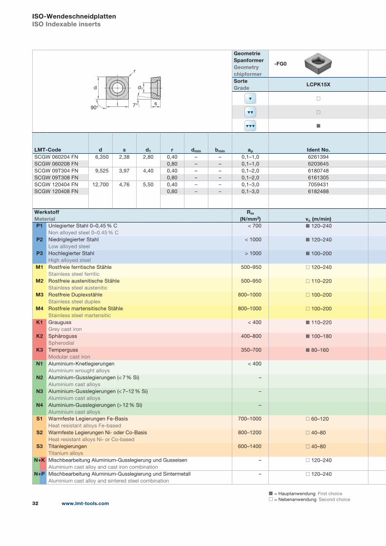
LMT-Code d s d1 r dmin bmin ap Ident No.SCGW 060204 FN 6,350 2,38 2,80 0,40 – – 0,1–1,0 6261394
SCGW 060208 FN 0,80 – – 0,1–1,0 6203645
SCGW 09T304 FN 9,525 3,97 4,40 0,40 – – 0,1–2,0 6180748
SCGW 09T308 FN 0,80 – – 0,1–2,0 6161305
SCGW 120404 FN 12,700 4,76 5,50 0,40 – – 0,1–3,0 7059431
SCGW 120408 FN 0,80 – – 0,1–3,0 6182488
WerkstoffMaterial
Rm
(N/mm2) vc (m/min)P1 Unlegierter Stahl 0–0,45 % C
Non alloyed steel 0–0.45 % C
< 700 ◼ 120–240
P2 Niedriglegierter Stahl
Low alloyed steel
< 1000 ◼ 120–240
P3 Hochlegierter Stahl
High alloyed steel
> 1000 ◼ 100–200
M1 Rostfreie ferritische Stähle
Stainless steel ferritic
500–950 ◻ 120–240
M2 Rostfreie austenitische Stähle
Stainless steel austenitic
500–950 ◻ 110–220
M3 Rostfreie Duplexstähle
Stainless steel duplex
800–1000 ◻ 100–200
M4 Rostfreie martensitische Stähle
Stainless steel martensitic
800–1000 ◻ 100–200
K1 Grauguss
Grey cast iron
< 400 ◼ 110–220
K2 Sphäroguss
Spherodial
400–800 ◼ 100–180
K3 Temperguss
Modular cast iron
350–700 ◼ 80–160
N1 Aluminium-Knetlegierungen
Aluminium wrought alloys
< 400
N2 Aluminium-Gusslegierungen (< 7 % Si)
Aluminium cast alloys
–
N3 Aluminium-Gusslegierungen (< 7–12 % Si)
Aluminium cast alloys
–
N4 Aluminium-Gusslegierungen (> 12 % Si)
Aluminium cast alloys
–
S1 Warmfeste Legierungen Fe-Basis
Heat resistant alloys Fe-based
700–1000 ◻ 60–120
S2 Warmfeste Legierungen Ni- oder Co-Basis
Heat resistant alloys Ni- or Co-based
800–1200 ◻ 40–80
S3 Titanlegierungen
Titanium alloys
600–1400 ◻ 40–80
N K Mischbearbeitung Aluminium-Gusslegierung und Gusseisen
Aluminium cast alloy and cast iron combination
– ◻ 120–240
N P Mischbearbeitung Aluminium-Gusslegierung und Sintermetall
Aluminium cast alloy and sintered steel combination
– ◻ 120–240
+
+
1) Wert fz abhängig von Spanformer Geometrie (siehe Vorschubempfehlungen unten)
fz figure depending on chip breaker geometry (see feed recommendations below)
Ident No. Ident No.
AnzugsmomentTorque
(Nm)6119612 T7 1,0
6119602 T15 4,0
6119603 T20 6,5
vc (m/min) vc (m/min)Vorschub Feed (mm/z)
FG0
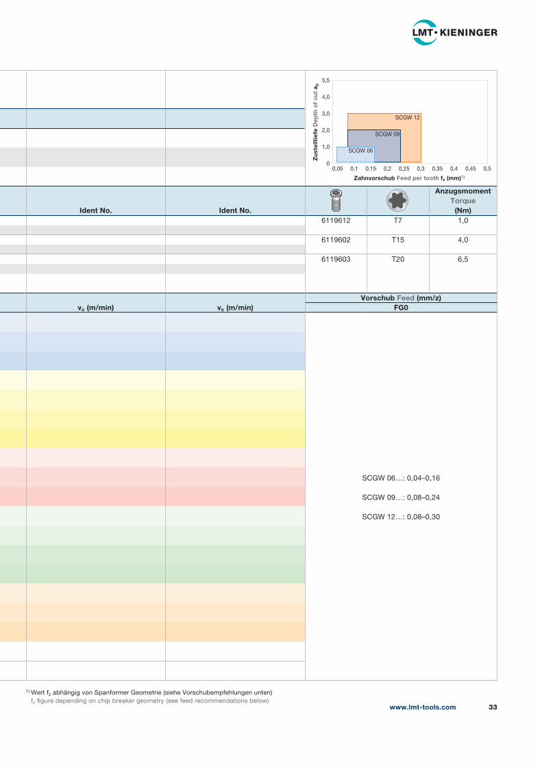
SCGW 06…: 0,04–0,16
SCGW 09…: 0,08–0,24
SCGW 12…: 0,08–0,30
www.lmt-tools.com 33
5,5
4,0
3,0
2,0
1,0
00,05 0,1 0,15 0,2 0,25 0,3 0,35 0,4 0,45 0,5
Zahnvorschub Feed per tooth fz (mm)1)
Zu
stel
ltie
fe D
epth
of
cut
a p
SCGW 06
SCGW 12
SCGW 09
◼ = Hauptanwendung First choice
◻ = Nebenanwendung Second choice
+
+
www.lmt-tools.com34
ISO-WendeschneidplattenISO Indexable inserts
r
d
lB
l
s90° 7°
d1
Geometrie SpanformerGeometrychipformer
-FG0
SorteGrade
LBHK95X1
◻
◻
◼
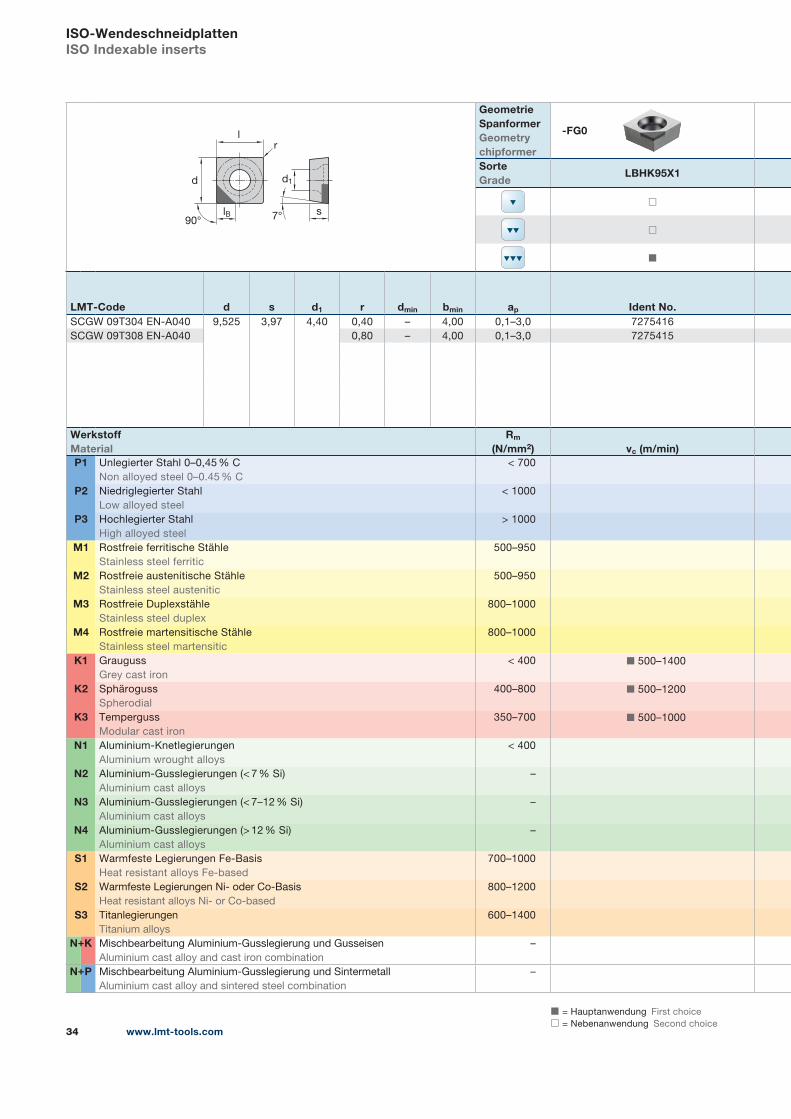
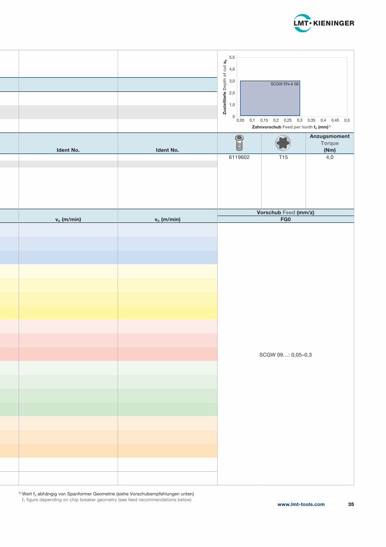
LMT-Code d s d1 r dmin bmin ap Ident No.SCGW 09T304 EN-A040 9,525 3,97 4,40 0,40 – 4,00 0,1–3,0 7275416
SCGW 09T308 EN-A040 0,80 – 4,00 0,1–3,0 7275415
WerkstoffMaterial
Rm
(N/mm2) vc (m/min)P1 Unlegierter Stahl 0–0,45 % C
Non alloyed steel 0–0.45 % C
< 700
P2 Niedriglegierter Stahl
Low alloyed steel
< 1000
P3 Hochlegierter Stahl
High alloyed steel
> 1000
M1 Rostfreie ferritische Stähle
Stainless steel ferritic
500–950
M2 Rostfreie austenitische Stähle
Stainless steel austenitic
500–950
M3 Rostfreie Duplexstähle
Stainless steel duplex
800–1000
M4 Rostfreie martensitische Stähle
Stainless steel martensitic
800–1000
K1 Grauguss
Grey cast iron
< 400 ◼ 500–1400
K2 Sphäroguss
Spherodial
400–800 ◼ 500–1200
K3 Temperguss
Modular cast iron
350–700 ◼ 500–1000
N1 Aluminium-Knetlegierungen
Aluminium wrought alloys
< 400
N2 Aluminium-Gusslegierungen (< 7 % Si)
Aluminium cast alloys
–
N3 Aluminium-Gusslegierungen (< 7–12 % Si)
Aluminium cast alloys
–
N4 Aluminium-Gusslegierungen (> 12 % Si)
Aluminium cast alloys
–
S1 Warmfeste Legierungen Fe-Basis
Heat resistant alloys Fe-based
700–1000
S2 Warmfeste Legierungen Ni- oder Co-Basis
Heat resistant alloys Ni- or Co-based
800–1200
S3 Titanlegierungen
Titanium alloys
600–1400
N K Mischbearbeitung Aluminium-Gusslegierung und Gusseisen
Aluminium cast alloy and cast iron combination
–
N P Mischbearbeitung Aluminium-Gusslegierung und Sintermetall
Aluminium cast alloy and sintered steel combination
–
+
+
1) Wert fz abhängig von Spanformer Geometrie (siehe Vorschubempfehlungen unten)
fz figure depending on chip breaker geometry (see feed recommendations below)
Ident No. Ident No.
AnzugsmomentTorque
(Nm)6119602 T15 4,0
vc (m/min) vc (m/min)Vorschub Feed (mm/z)
FG0
SCGW 09…: 0,05–0,3
www.lmt-tools.com 35
5,5
4,0
3,0
2,0
1,0
00,05 0,1 0,15 0,2 0,25 0,3 0,35 0,4 0,45 0,5
Zahnvorschub Feed per tooth fz (mm)1)
Zu
stel
ltie
fe D
epth
of
cut
a p
SCGW EN-A 09

◼ = Hauptanwendung First choice
◻ = Nebenanwendung Second choice
+
+
www.lmt-tools.com36
ISO-WendeschneidplattenISO Indexable inserts
s7°
d1
r
l
d
90°
Geometrie SpanformerGeometrychipformer
-FS12
SorteGrade
LCKP10X
◼
◼
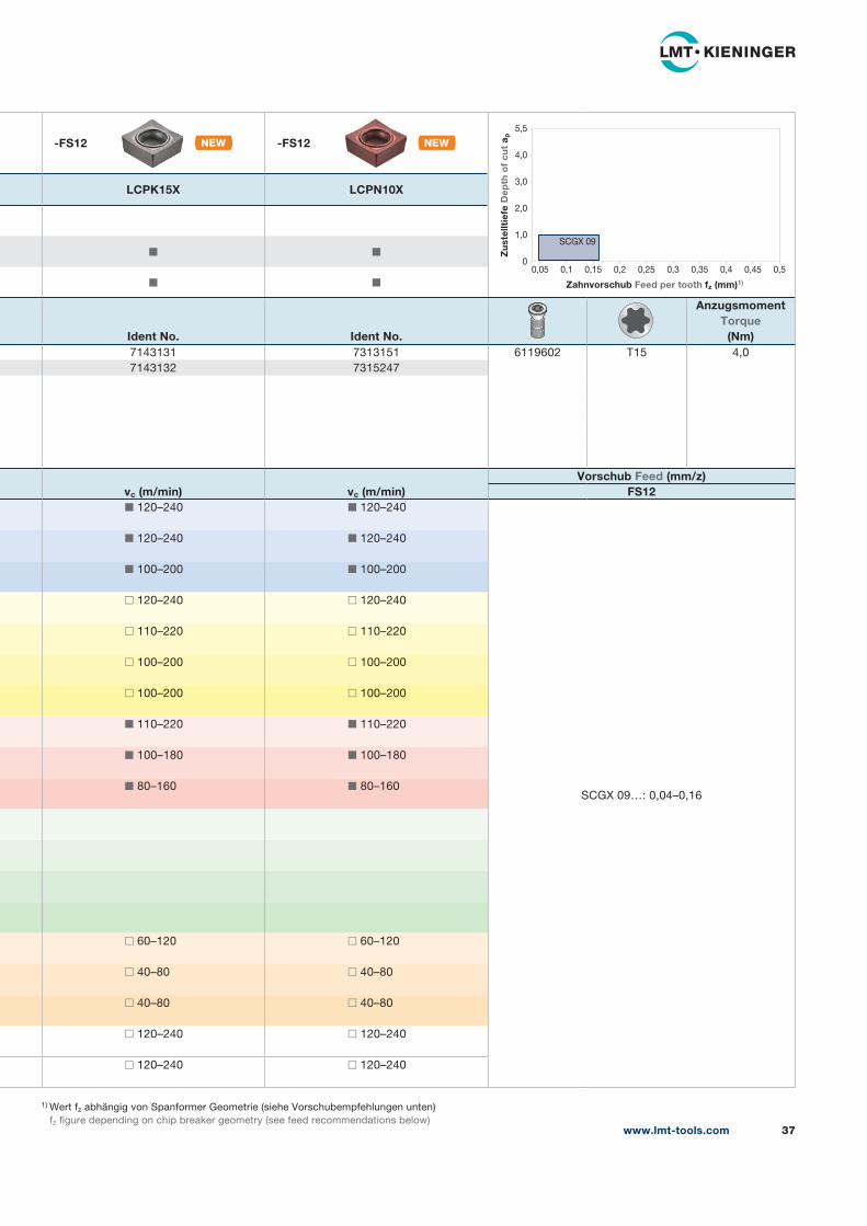
LMT-Code d s d1 r dmin bmin ap Ident No.SCGX 09T304 FN 9,525 3,97 4,40 0,40 – – 0,05–1,0 7143121
SCGX 09T308 FN 0,80 – – 0,05–1,0 7143122
WerkstoffMaterial
Rm
(N/mm2) vc (m/min)P1 Unlegierter Stahl 0–0,45 % C
Non alloyed steel 0–0.45 % C
< 700 ◼ 120–240
P2 Niedriglegierter Stahl
Low alloyed steel
< 1000 ◼ 120–240
P3 Hochlegierter Stahl
High alloyed steel
> 1000 ◼ 100–200
M1 Rostfreie ferritische Stähle
Stainless steel ferritic
500–950 ◻ 120–240
M2 Rostfreie austenitische Stähle
Stainless steel austenitic
500–950 ◻ 110–220
M3 Rostfreie Duplexstähle
Stainless steel duplex
800–1000 ◻ 100–200
M4 Rostfreie martensitische Stähle
Stainless steel martensitic
800–1000 ◻ 100–200
K1 Grauguss
Grey cast iron
< 400 ◼ 110–220
K2 Sphäroguss
Spherodial
400–800 ◼ 100–180
K3 Temperguss
Modular cast iron
350–700 ◼ 80–160
N1 Aluminium-Knetlegierungen
Aluminium wrought alloys
< 400
N2 Aluminium-Gusslegierungen (< 7 % Si)
Aluminium cast alloys
–
N3 Aluminium-Gusslegierungen (< 7–12 % Si)
Aluminium cast alloys
–
N4 Aluminium-Gusslegierungen (> 12 % Si)
Aluminium cast alloys
–
S1 Warmfeste Legierungen Fe-Basis
Heat resistant alloys Fe-based
700–1000 ◻ 60–120
S2 Warmfeste Legierungen Ni- oder Co-Basis
Heat resistant alloys Ni- or Co-based
800–1200 ◻ 40–80
S3 Titanlegierungen
Titanium alloys
600–1400 ◻ 40–80
N K Mischbearbeitung Aluminium-Gusslegierung und Gusseisen
Aluminium cast alloy and cast iron combination
– ◻ 120–240
N P Mischbearbeitung Aluminium-Gusslegierung und Sintermetall
Aluminium cast alloy and sintered steel combination
– ◻ 120–240
+
+
1) Wert fz abhängig von Spanformer Geometrie (siehe Vorschubempfehlungen unten)
fz figure depending on chip breaker geometry (see feed recommendations below)
-FS12 -FS12
LCPK15X LCPN10X
◼ ◼
◼ ◼
Ident No. Ident No.
AnzugsmomentTorque
(Nm)7143131 7313151 6119602 T15 4,0
7143132 7315247
vc (m/min) vc (m/min)Vorschub Feed (mm/z)
FS12◼ 120–240 ◼ 120–240
SCGX 09…: 0,04–0,16
◼ 120–240 ◼ 120–240
◼ 100–200 ◼ 100–200
◻ 120–240 ◻ 120–240
◻ 110–220 ◻ 110–220
◻ 100–200 ◻ 100–200
◻ 100–200 ◻ 100–200
◼ 110–220 ◼ 110–220
◼ 100–180 ◼ 100–180
◼ 80–160 ◼ 80–160
◻ 60–120 ◻ 60–120
◻ 40–80 ◻ 40–80
◻ 40–80 ◻ 40–80
◻ 120–240 ◻ 120–240
◻ 120–240 ◻ 120–240
www.lmt-tools.com 37
5,5
4,0
3,0
2,0
1,0
00,05 0,1 0,15 0,2 0,25 0,3 0,35 0,4 0,45 0,5
Zahnvorschub Feed per tooth fz (mm)1)
Zu
stel
ltie
fe D
epth
of
cut
a p
SCGX 09

◼ = Hauptanwendung First choice
◻ = Nebenanwendung Second choice
+
+
www.lmt-tools.com38
ISO-WendeschneidplattenISO Indexable inserts
7°
d1
s
r
l
d
90°
Geometrie SpanformerGeometrychipformer
-FS7
SorteGrade
LCP15X
◻
◼
◼
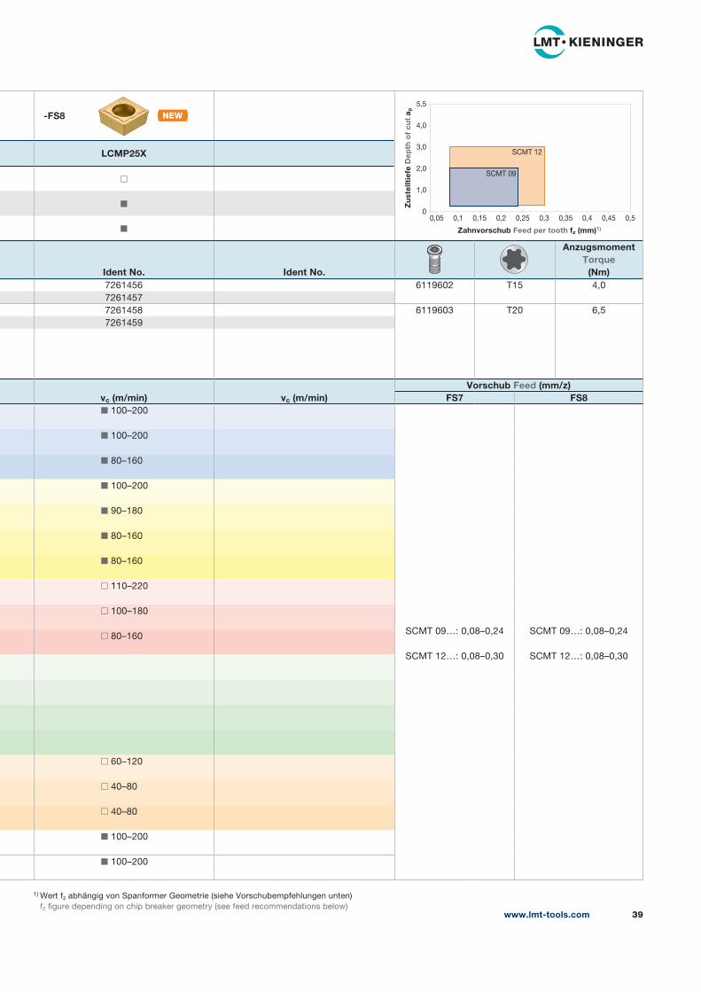
LMT-Code d s d1 r dmin bmin ap Ident No.SCMT 09T304 EN 9,525 3,97 4,40 0,40 – – 0,25–2,0 7261452
SCMT 09T308 EN 0,80 – – 0,25–2,0 7261453
SCMT 120404 EN 12,700 4,76 5,50 0,40 – – 0,30–3,0 7261454
SCMT 120408 EN 0,80 – – 0,30–3,0 7261455
WerkstoffMaterial
Rm
(N/mm2) vc (m/min)P1 Unlegierter Stahl 0–0,45 % C
Non alloyed steel 0–0.45 % C
< 700 ◼ 160–240
P2 Niedriglegierter Stahl
Low alloyed steel
< 1000 ◼ 160–240
P3 Hochlegierter Stahl
High alloyed steel
> 1000 ◼ 120–200
M1 Rostfreie ferritische Stähle
Stainless steel ferritic
500–950 ◻ 80–160
M2 Rostfreie austenitische Stähle
Stainless steel austenitic
500–950 ◻ 80–160
M3 Rostfreie Duplexstähle
Stainless steel duplex
800–1000 ◻ 60–120
M4 Rostfreie martensitische Stähle
Stainless steel martensitic
800–1000 ◻ 60–120
K1 Grauguss
Grey cast iron
< 400
K2 Sphäroguss
Spherodial
400–800
K3 Temperguss
Modular cast iron
350–700
N1 Aluminium-Knetlegierungen
Aluminium wrought alloys
< 400
N2 Aluminium-Gusslegierungen (< 7 % Si)
Aluminium cast alloys
–
N3 Aluminium-Gusslegierungen (< 7–12 % Si)
Aluminium cast alloys
–
N4 Aluminium-Gusslegierungen (> 12 % Si)
Aluminium cast alloys
–
S1 Warmfeste Legierungen Fe-Basis
Heat resistant alloys Fe-based
700–1000
S2 Warmfeste Legierungen Ni- oder Co-Basis
Heat resistant alloys Ni- or Co-based
800–1200
S3 Titanlegierungen
Titanium alloys
600–1400
N K Mischbearbeitung Aluminium-Gusslegierung und Gusseisen
Aluminium cast alloy and cast iron combination
–
N P Mischbearbeitung Aluminium-Gusslegierung und Sintermetall
Aluminium cast alloy and sintered steel combination
–
+
+
1) Wert fz abhängig von Spanformer Geometrie (siehe Vorschubempfehlungen unten)
fz figure depending on chip breaker geometry (see feed recommendations below)
-FS8
LCMP25X
◻
◼
◼
Ident No. Ident No.
AnzugsmomentTorque
(Nm)7261456 6119602 T15 4,0
7261457
7261458 6119603 T20 6,5
7261459
vc (m/min) vc (m/min)Vorschub Feed (mm/z)
FS7 FS8◼ 100–200
SCMT 09…: 0,08–0,24
SCMT 12…: 0,08–0,30
SCMT 09…: 0,08–0,24
SCMT 12…: 0,08–0,30
◼ 100–200
◼ 80–160
◼ 100–200
◼ 90–180
◼ 80–160
◼ 80–160
◻ 110–220
◻ 100–180
◻ 80–160
◻ 60–120
◻ 40–80
◻ 40–80
◼ 100–200
◼ 100–200
www.lmt-tools.com 39
5,5
4,0
3,0
2,0
1,0
00,05 0,1 0,15 0,2 0,25 0,3 0,35 0,4 0,45 0,5
Zahnvorschub Feed per tooth fz (mm)1)
Zu
stel
ltie
fe D
epth
of
cut
a p
SCMT 12
SCMT 09
◼ = Hauptanwendung First choice
◻ = Nebenanwendung Second choice
+
+
www.lmt-tools.com40
ISO-WendeschneidplattenISO Indexable inserts
7° s
d1
r
l
d
60°
Geometrie SpanformerGeometrychipformer
L-FG10
SorteGrade
LCPK15X
◼
◼
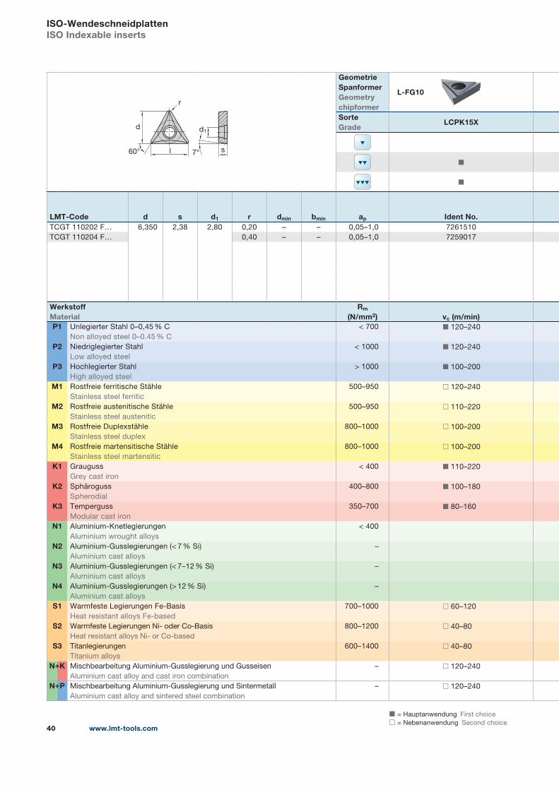
LMT-Code d s d1 r dmin bmin ap Ident No.TCGT 110202 F… 6,350 2,38 2,80 0,20 – – 0,05–1,0 7261510
TCGT 110204 F… 0,40 – – 0,05–1,0 7259017
WerkstoffMaterial
Rm
(N/mm2) vc (m/min)P1 Unlegierter Stahl 0–0,45 % C
Non alloyed steel 0–0.45 % C
< 700 ◼ 120–240
P2 Niedriglegierter Stahl
Low alloyed steel
< 1000 ◼ 120–240
P3 Hochlegierter Stahl
High alloyed steel
> 1000 ◼ 100–200
M1 Rostfreie ferritische Stähle
Stainless steel ferritic
500–950 ◻ 120–240
M2 Rostfreie austenitische Stähle
Stainless steel austenitic
500–950 ◻ 110–220
M3 Rostfreie Duplexstähle
Stainless steel duplex
800–1000 ◻ 100–200
M4 Rostfreie martensitische Stähle
Stainless steel martensitic
800–1000 ◻ 100–200
K1 Grauguss
Grey cast iron
< 400 ◼ 110–220
K2 Sphäroguss
Spherodial
400–800 ◼ 100–180
K3 Temperguss
Modular cast iron
350–700 ◼ 80–160
N1 Aluminium-Knetlegierungen
Aluminium wrought alloys
< 400
N2 Aluminium-Gusslegierungen (< 7 % Si)
Aluminium cast alloys
–
N3 Aluminium-Gusslegierungen (< 7–12 % Si)
Aluminium cast alloys
–
N4 Aluminium-Gusslegierungen (> 12 % Si)
Aluminium cast alloys
–
S1 Warmfeste Legierungen Fe-Basis
Heat resistant alloys Fe-based
700–1000 ◻ 60–120
S2 Warmfeste Legierungen Ni- oder Co-Basis
Heat resistant alloys Ni- or Co-based
800–1200 ◻ 40–80
S3 Titanlegierungen
Titanium alloys
600–1400 ◻ 40–80
N K Mischbearbeitung Aluminium-Gusslegierung und Gusseisen
Aluminium cast alloy and cast iron combination
– ◻ 120–240
N P Mischbearbeitung Aluminium-Gusslegierung und Sintermetall
Aluminium cast alloy and sintered steel combination
– ◻ 120–240
+
+
1) Wert fz abhängig von Spanformer Geometrie (siehe Vorschubempfehlungen unten)
fz figure depending on chip breaker geometry (see feed recommendations below)
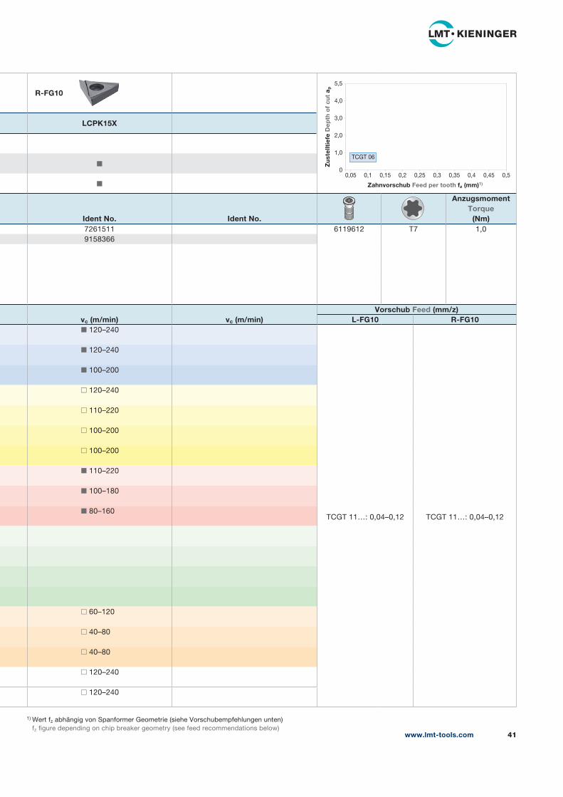
R-FG10
LCPK15X
◼
◼
Ident No. Ident No.
AnzugsmomentTorque
(Nm)7261511 6119612 T7 1,0
9158366
vc (m/min) vc (m/min)Vorschub Feed (mm/z)
L-FG10 R-FG10◼ 120–240
TCGT 11…: 0,04–0,12 TCGT 11…: 0,04–0,12
◼ 120–240
◼ 100–200
◻ 120–240
◻ 110–220
◻ 100–200
◻ 100–200
◼ 110–220
◼ 100–180
◼ 80–160
◻ 60–120
◻ 40–80
◻ 40–80
◻ 120–240
◻ 120–240
www.lmt-tools.com 41
5,5
4,0
3,0
2,0
1,0
00,05 0,1 0,15 0,2 0,25 0,3 0,35 0,4 0,45 0,5
Zahnvorschub Feed per tooth fz (mm)1)
Zu
stel
ltie
fe D
epth
of
cut
a p
TCGT 06

◼ = Hauptanwendung First choice
◻ = Nebenanwendung Second choice
+
+
www.lmt-tools.com42
ISO-WendeschneidplattenISO Indexable inserts
d1
r
l
d
60° 7° s
Geometrie SpanformerGeometrychipformer
-FG0
SorteGrade
LCPK15X
◻
◻
◼
LMT-Code d s d1 r dmin bmin ap Ident No.TCGW 090202 FN 5,560 2,38 2,50 0,20 – – 0,1–1,0 7061298
TCGW 090204 FN 0,40 – – 0,1–1,0 7118060
TCGW 110202 FN 6,350 2,38 2,80 0,20 – – 0,1–1,0 7161592
TCGW 110204 FN 0,40 – – 0,1–1,0 6202743
TCGW 110208 FN 0,80 – – 0,1–1,0 9071427
TCGW 16T304 FN 9,525 3,97 4,40 0,40 – – 0,1–2,0 7061297
TCGW 16T308 FN 0,80 – – 0,1–2,0 6145080
WerkstoffMaterial
Rm
(N/mm2) vc (m/min)P1 Unlegierter Stahl 0–0,45 % C
Non alloyed steel 0–0.45 % C
< 700 ◼ 120–240
P2 Niedriglegierter Stahl
Low alloyed steel
< 1000 ◼ 120–240
P3 Hochlegierter Stahl
High alloyed steel
> 1000 ◼ 100–200
M1 Rostfreie ferritische Stähle
Stainless steel ferritic
500–950 ◻ 120–240
M2 Rostfreie austenitische Stähle
Stainless steel austenitic
500–950 ◻ 110–220
M3 Rostfreie Duplexstähle
Stainless steel duplex
800–1000 ◻ 100–200
M4 Rostfreie martensitische Stähle
Stainless steel martensitic
800–1000 ◻ 100–200
K1 Grauguss
Grey cast iron
< 400 ◼ 110–220
K2 Sphäroguss
Spherodial
400–800 ◼ 100–180
K3 Temperguss
Modular cast iron
350–700 ◼ 80–160
N1 Aluminium-Knetlegierungen
Aluminium wrought alloys
< 400
N2 Aluminium-Gusslegierungen (< 7 % Si)
Aluminium cast alloys
–
N3 Aluminium-Gusslegierungen (< 7–12 % Si)
Aluminium cast alloys
–
N4 Aluminium-Gusslegierungen (> 12 % Si)
Aluminium cast alloys
–
S1 Warmfeste Legierungen Fe-Basis
Heat resistant alloys Fe-based
700–1000 ◻ 60–120
S2 Warmfeste Legierungen Ni- oder Co-Basis
Heat resistant alloys Ni- or Co-based
800–1200 ◻ 40–80
S3 Titanlegierungen
Titanium alloys
600–1400 ◻ 40–80
N K Mischbearbeitung Aluminium-Gusslegierung und Gusseisen
Aluminium cast alloy and cast iron combination
– ◻ 120–240
N P Mischbearbeitung Aluminium-Gusslegierung und Sintermetall
Aluminium cast alloy and sintered steel combination
– ◻ 120–240
+
+
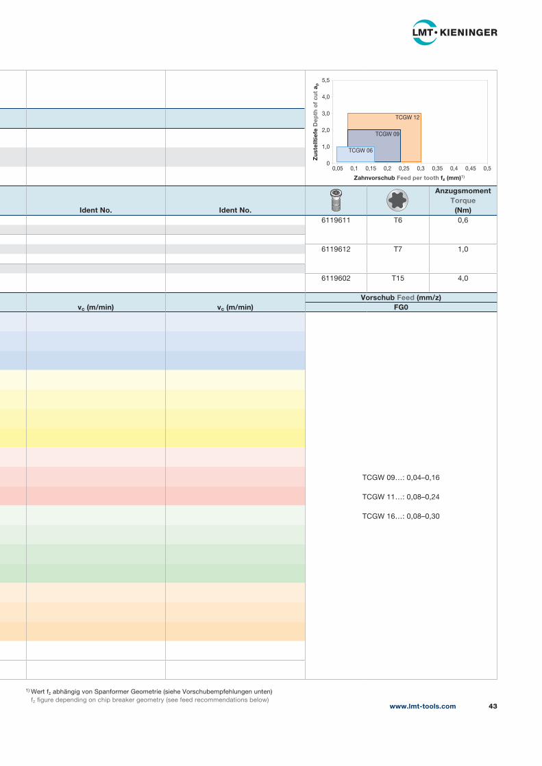
1) Wert fz abhängig von Spanformer Geometrie (siehe Vorschubempfehlungen unten)
fz figure depending on chip breaker geometry (see feed recommendations below)
Ident No. Ident No.
AnzugsmomentTorque
(Nm)6119611 T6 0,6
6119612 T7 1,0
6119602 T15 4,0
vc (m/min) vc (m/min)Vorschub Feed (mm/z)
FG0
TCGW 09…: 0,04–0,16
TCGW 11…: 0,08–0,24
TCGW 16…: 0,08–0,30
www.lmt-tools.com 43
5,5
4,0
3,0
2,0
1,0
00,05 0,1 0,15 0,2 0,25 0,3 0,35 0,4 0,45 0,5
Zahnvorschub Feed per tooth fz (mm)1)
Zu
stel
ltie
fe D
epth
of
cut
a p
TCGW 06
TCGW 12
TCGW 09
SPEZIFISCHE WENDESCHNEIDPLATTEN
www.lmt-tools.com 45
Spezifische WendeschneidplattenSpecific Indexable inserts
46 CP -FG0
48 SP -FG0
50 TP -FG0
Wendeschneidplatten nach Hausnorm
siehe Seite 13 + Ausklappseite.
Indexable inserts according to in-house standard
see page 13 + pop up page.
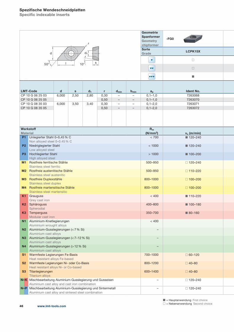
◼ = Hauptanwendung First choice
◻ = Nebenanwendung Second choice
+
+
www.lmt-tools.com46
Spezifische WendeschneidplattenSpecific indexable inserts
r
l s
d
10°50°
d1
Geometrie SpanformerGeometrychipformer
-FG0
SorteGrade
LCPK15X
◻
◻
◼
LMT-Code d s d1 r dmin bmin ap Ident No.CP 10 G 06 25 03 6,000 2,50 2,80 0,30 – – 0,1–1,0 7263068
CP 10 G 06 25 05 0,50 – – 0,1–1,0 7263070
CP 10 G 08 35 03 6,000 3,50 3,40 0,30 – – 0,1–2,0 7263071
CP 10 G 08 35 05 0,50 – – 0,1–2,0 7263072
WerkstoffMaterial
Rm
(N/mm2) vc (m/min)P1 Unlegierter Stahl 0–0,45 % C
Non alloyed steel 0–0.45 % C
< 700 ◼ 120–240
P2 Niedriglegierter Stahl
Low alloyed steel
< 1000 ◼ 120–240
P3 Hochlegierter Stahl
High alloyed steel
> 1000 ◼ 100–200
M1 Rostfreie ferritische Stähle
Stainless steel ferritic
500–950 ◻ 120–240
M2 Rostfreie austenitische Stähle
Stainless steel austenitic
500–950 ◻ 110–220
M3 Rostfreie Duplexstähle
Stainless steel duplex
800–1000 ◻ 100–200
M4 Rostfreie martensitische Stähle
Stainless steel martensitic
800–1000 ◻ 100–200
K1 Grauguss
Grey cast iron
< 400 ◼ 110–220
K2 Sphäroguss
Spherodial
400–800 ◼ 100–180
K3 Temperguss
Modular cast iron
350–700 ◼ 80–160
N1 Aluminium-Knetlegierungen
Aluminium wrought alloys
< 400
N2 Aluminium-Gusslegierungen (< 7 % Si)
Aluminium cast alloys
–
N3 Aluminium-Gusslegierungen (< 7–12 % Si)
Aluminium cast alloys
–
N4 Aluminium-Gusslegierungen (> 12 % Si)
Aluminium cast alloys
–
S1 Warmfeste Legierungen Fe-Basis
Heat resistant alloys Fe-based
700–1000 ◻ 60–120
S2 Warmfeste Legierungen Ni- oder Co-Basis
Heat resistant alloys Ni- or Co-based
800–1200 ◻ 40–80
S3 Titanlegierungen
Titanium alloys
600–1400 ◻ 40–80
N K Mischbearbeitung Aluminium-Gusslegierung und Gusseisen
Aluminium cast alloy and cast iron combination
– ◻ 120–240
N P Mischbearbeitung Aluminium-Gusslegierung und Sintermetall
Aluminium cast alloy and sintered steel combination
– ◻ 120–240
+
+
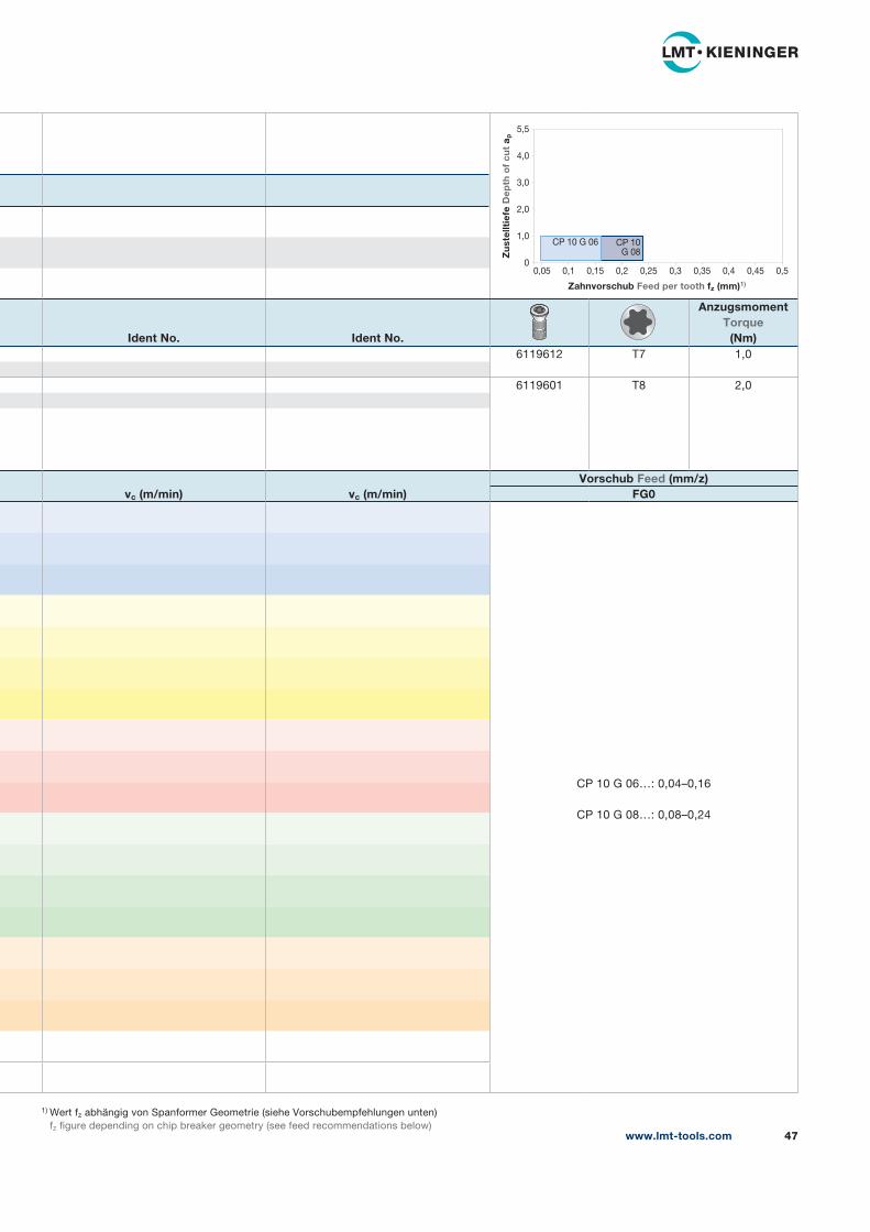
1) Wert fz abhängig von Spanformer Geometrie (siehe Vorschubempfehlungen unten)
fz figure depending on chip breaker geometry (see feed recommendations below)
Ident No. Ident No.
AnzugsmomentTorque
(Nm)6119612 T7 1,0
6119601 T8 2,0
vc (m/min) vc (m/min)Vorschub Feed (mm/z)
FG0
CP 10 G 06…: 0,04–0,16
CP 10 G 08…: 0,08–0,24
www.lmt-tools.com 47
5,5
4,0
3,0
2,0
1,0
00,05 0,1 0,15 0,2 0,25 0,3 0,35 0,4 0,45 0,5
Zahnvorschub Feed per tooth fz (mm)1)
Zu
stel
ltie
fe D
epth
of
cut
a p
CP 10 G 06 CP 10G 08
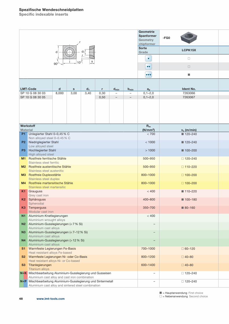
◼ = Hauptanwendung First choice
◻ = Nebenanwendung Second choice
+
+
www.lmt-tools.com48
Spezifische WendeschneidplattenSpecific indexable inserts
s
d1
r
l
d
90° 10°
Geometrie SpanformerGeometrychipformer
-FG0
SorteGrade
LCPK15X
◻
◻
◼
LMT-Code d s d1 r dmin bmin ap Ident No.SP 10 G 08 30 03 8,000 3,00 3,40 0,30 – – 0,1–2,0 7263066
SP 10 G 08 30 05 0,50 – – 0,1–2,0 7263067
WerkstoffMaterial
Rm
(N/mm2) vc (m/min)P1 Unlegierter Stahl 0–0,45 % C
Non alloyed steel 0–0.45 % C
< 700 ◼ 120–240
P2 Niedriglegierter Stahl
Low alloyed steel
< 1000 ◼ 120–240
P3 Hochlegierter Stahl
High alloyed steel
> 1000 ◼ 100–200
M1 Rostfreie ferritische Stähle
Stainless steel ferritic
500–950 ◻ 120–240
M2 Rostfreie austenitische Stähle
Stainless steel austenitic
500–950 ◻ 110–220
M3 Rostfreie Duplexstähle
Stainless steel duplex
800–1000 ◻ 100–200
M4 Rostfreie martensitische Stähle
Stainless steel martensitic
800–1000 ◻ 100–200
K1 Grauguss
Grey cast iron
< 400 ◼ 110–220
K2 Sphäroguss
Spherodial
400–800 ◼ 100–180
K3 Temperguss
Modular cast iron
350–700 ◼ 80–160
N1 Aluminium-Knetlegierungen
Aluminium wrought alloys
< 400
N2 Aluminium-Gusslegierungen (< 7 % Si)
Aluminium cast alloys
–
N3 Aluminium-Gusslegierungen (< 7–12 % Si)
Aluminium cast alloys
–
N4 Aluminium-Gusslegierungen (> 12 % Si)
Aluminium cast alloys
–
S1 Warmfeste Legierungen Fe-Basis
Heat resistant alloys Fe-based
700–1000 ◻ 60–120
S2 Warmfeste Legierungen Ni- oder Co-Basis
Heat resistant alloys Ni- or Co-based
800–1200 ◻ 40–80
S3 Titanlegierungen
Titanium alloys
600–1400 ◻ 40–80
N K Mischbearbeitung Aluminium-Gusslegierung und Gusseisen
Aluminium cast alloy and cast iron combination
– ◻ 120–240
N P Mischbearbeitung Aluminium-Gusslegierung und Sintermetall
Aluminium cast alloy and sintered steel combination
– ◻ 120–240
+
+
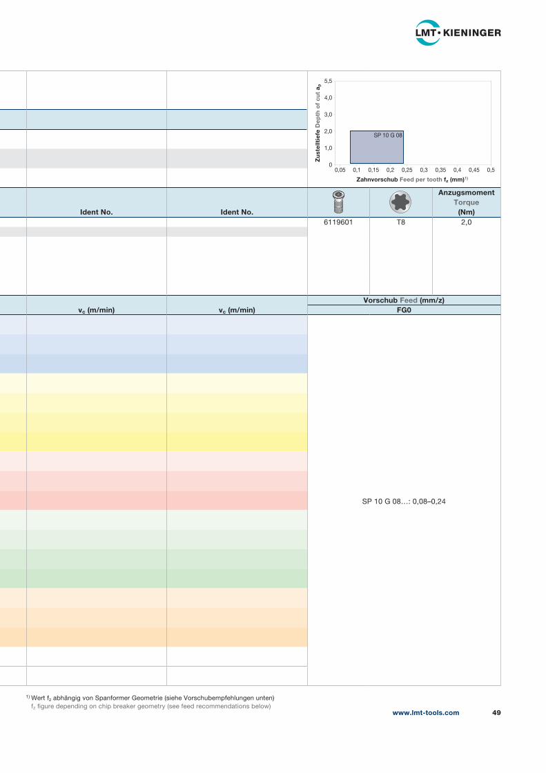
1) Wert fz abhängig von Spanformer Geometrie (siehe Vorschubempfehlungen unten)
fz figure depending on chip breaker geometry (see feed recommendations below)
Ident No. Ident No.
AnzugsmomentTorque
(Nm)6119601 T8 2,0
vc (m/min) vc (m/min)Vorschub Feed (mm/z)
FG0
SP 10 G 08…: 0,08–0,24
www.lmt-tools.com 49
5,5
4,0
3,0
2,0
1,0
00,05 0,1 0,15 0,2 0,25 0,3 0,35 0,4 0,45 0,5
Zahnvorschub Feed per tooth fz (mm)1)
Zu
stel
ltie
fe D
epth
of
cut
a p
SP 10 G 08
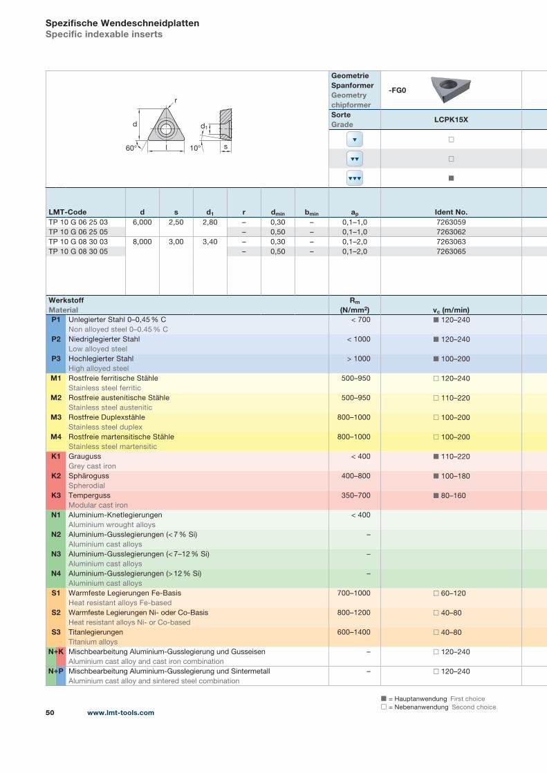
◼ = Hauptanwendung First choice
◻ = Nebenanwendung Second choice
+
+
www.lmt-tools.com50
Spezifische WendeschneidplattenSpecific indexable inserts
s
d1
r
l
d
60° 10°
Geometrie SpanformerGeometrychipformer
-FG0
SorteGrade
LCPK15X
◻
◻
◼
LMT-Code d s d1 r dmin bmin ap Ident No.TP 10 G 06 25 03 6,000 2,50 2,80 – 0,30 – 0,1–1,0 7263059
TP 10 G 06 25 05 – 0,50 – 0,1–1,0 7263062
TP 10 G 08 30 03 8,000 3,00 3,40 – 0,30 – 0,1–2,0 7263063
TP 10 G 08 30 05 – 0,50 – 0,1–2,0 7263065
WerkstoffMaterial
Rm
(N/mm2) vc (m/min)P1 Unlegierter Stahl 0–0,45 % C
Non alloyed steel 0–0.45 % C
< 700 ◼ 120–240
P2 Niedriglegierter Stahl
Low alloyed steel
< 1000 ◼ 120–240
P3 Hochlegierter Stahl
High alloyed steel
> 1000 ◼ 100–200
M1 Rostfreie ferritische Stähle
Stainless steel ferritic
500–950 ◻ 120–240
M2 Rostfreie austenitische Stähle
Stainless steel austenitic
500–950 ◻ 110–220
M3 Rostfreie Duplexstähle
Stainless steel duplex
800–1000 ◻ 100–200
M4 Rostfreie martensitische Stähle
Stainless steel martensitic
800–1000 ◻ 100–200
K1 Grauguss
Grey cast iron
< 400 ◼ 110–220
K2 Sphäroguss
Spherodial
400–800 ◼ 100–180
K3 Temperguss
Modular cast iron
350–700 ◼ 80–160
N1 Aluminium-Knetlegierungen
Aluminium wrought alloys
< 400
N2 Aluminium-Gusslegierungen (< 7 % Si)
Aluminium cast alloys
–
N3 Aluminium-Gusslegierungen (< 7–12 % Si)
Aluminium cast alloys
–
N4 Aluminium-Gusslegierungen (> 12 % Si)
Aluminium cast alloys
–
S1 Warmfeste Legierungen Fe-Basis
Heat resistant alloys Fe-based
700–1000 ◻ 60–120
S2 Warmfeste Legierungen Ni- oder Co-Basis
Heat resistant alloys Ni- or Co-based
800–1200 ◻ 40–80
S3 Titanlegierungen
Titanium alloys
600–1400 ◻ 40–80
N K Mischbearbeitung Aluminium-Gusslegierung und Gusseisen
Aluminium cast alloy and cast iron combination
– ◻ 120–240
N P Mischbearbeitung Aluminium-Gusslegierung und Sintermetall
Aluminium cast alloy and sintered steel combination
– ◻ 120–240
+
+
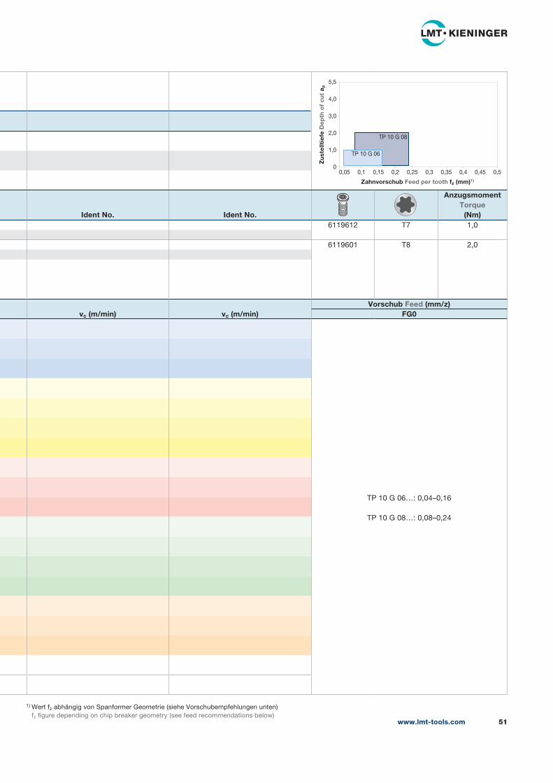
1) Wert fz abhängig von Spanformer Geometrie (siehe Vorschubempfehlungen unten)
fz figure depending on chip breaker geometry (see feed recommendations below)
Ident No. Ident No.
AnzugsmomentTorque
(Nm)6119612 T7 1,0
6119601 T8 2,0
vc (m/min) vc (m/min)Vorschub Feed (mm/z)
FG0
TP 10 G 06…: 0,04–0,16
TP 10 G 08…: 0,08–0,24
www.lmt-tools.com 51
5,5
4,0
3,0
2,0
1,0
00,05 0,1 0,15 0,2 0,25 0,3 0,35 0,4 0,45 0,5
Zahnvorschub Feed per tooth fz (mm)1)
Zu
stel
ltie
fe D
epth
of
cut
a p
TP 10 G 06
TP 10 G 08
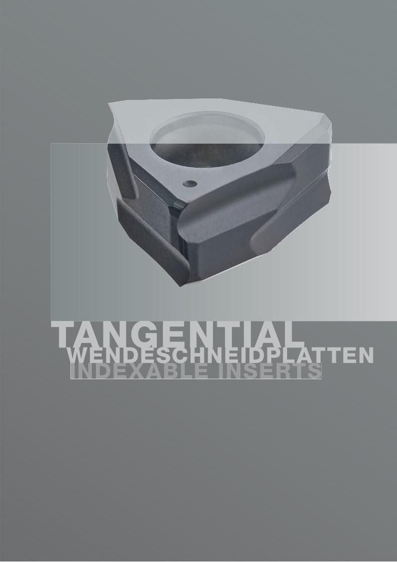
TANGENTIAL WENDESCHNEIDPLATTEN

www.lmt-tools.com 53
Tangential WendeschneidplattenTangential Indexable inserts
54 CNHX -UG15
56 LNEX -FS18
58 LNHU MultiFit tangential
62 WNNX -UG15
62 WNHX -UG15
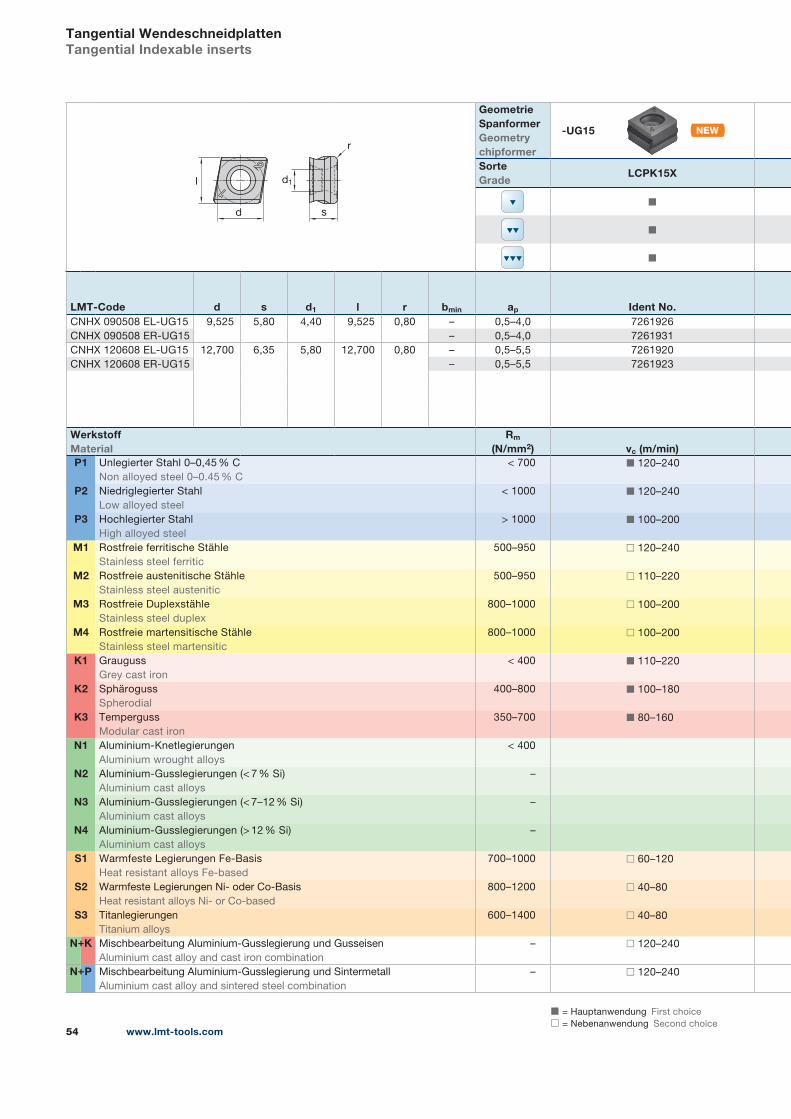
◼ = Hauptanwendung First choice
◻ = Nebenanwendung Second choice
+
+
www.lmt-tools.com54
Tangential WendeschneidplattenTangential Indexable inserts
r
2
1l
d s
d1
Geometrie SpanformerGeometrychipformer
-UG15
SorteGrade
LCPK15X
◼
◼
◼
LMT-Code d s d1 l r bmin ap Ident No.CNHX 090508 EL-UG15 9,525 5,80 4,40 9,525 0,80 – 0,5–4,0 7261926
CNHX 090508 ER-UG15 – 0,5–4,0 7261931
CNHX 120608 EL-UG15 12,700 6,35 5,80 12,700 0,80 – 0,5–5,5 7261920
CNHX 120608 ER-UG15 – 0,5–5,5 7261923
WerkstoffMaterial
Rm
(N/mm2) vc (m/min)P1 Unlegierter Stahl 0–0,45 % C
Non alloyed steel 0–0.45 % C
< 700 ◼ 120–240
P2 Niedriglegierter Stahl
Low alloyed steel
< 1000 ◼ 120–240
P3 Hochlegierter Stahl
High alloyed steel
> 1000 ◼ 100–200
M1 Rostfreie ferritische Stähle
Stainless steel ferritic
500–950 ◻ 120–240
M2 Rostfreie austenitische Stähle
Stainless steel austenitic
500–950 ◻ 110–220
M3 Rostfreie Duplexstähle
Stainless steel duplex
800–1000 ◻ 100–200
M4 Rostfreie martensitische Stähle
Stainless steel martensitic
800–1000 ◻ 100–200
K1 Grauguss
Grey cast iron
< 400 ◼ 110–220
K2 Sphäroguss
Spherodial
400–800 ◼ 100–180
K3 Temperguss
Modular cast iron
350–700 ◼ 80–160
N1 Aluminium-Knetlegierungen
Aluminium wrought alloys
< 400
N2 Aluminium-Gusslegierungen (< 7 % Si)
Aluminium cast alloys
–
N3 Aluminium-Gusslegierungen (< 7–12 % Si)
Aluminium cast alloys
–
N4 Aluminium-Gusslegierungen (> 12 % Si)
Aluminium cast alloys
–
S1 Warmfeste Legierungen Fe-Basis
Heat resistant alloys Fe-based
700–1000 ◻ 60–120
S2 Warmfeste Legierungen Ni- oder Co-Basis
Heat resistant alloys Ni- or Co-based
800–1200 ◻ 40–80
S3 Titanlegierungen
Titanium alloys
600–1400 ◻ 40–80
N K Mischbearbeitung Aluminium-Gusslegierung und Gusseisen
Aluminium cast alloy and cast iron combination
– ◻ 120–240
N P Mischbearbeitung Aluminium-Gusslegierung und Sintermetall
Aluminium cast alloy and sintered steel combination
– ◻ 120–240
+
+
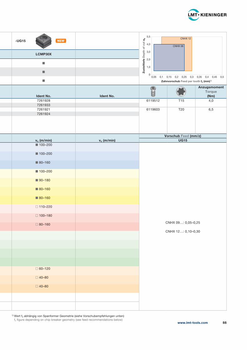
1) Wert fz abhängig von Spanformer Geometrie (siehe Vorschubempfehlungen unten)
fz figure depending on chip breaker geometry (see feed recommendations below)
-UG15
LCMP30X
◼
◼
◼
Ident No. Ident No.
AnzugsmomentTorque
(Nm)7261928 6119512 T15 4,0
7261933
7261921 6119603 T20 6,5
7261924
vc (m/min) vc (m/min)Vorschub Feed (mm/z)
UG15◼ 100–200
CNHX 09…: 0,05–0,25
CNHX 12…: 0,10–0,30
◼ 100–200
◼ 80–160
◼ 100–200
◼ 90–180
◼ 80–160
◼ 80–160
◻ 110–220
◻ 100–180
◻ 80–160
◻ 60–120
◻ 40–80
◻ 40–80
www.lmt-tools.com 55
5,5
4,0
3,0
2,0
1,0
00,05 0,1 0,15 0,2 0,25 0,3 0,35 0,4 0,45 0,5
Zahnvorschub Feed per tooth fz (mm)1)
Zu
stel
ltie
fe D
epth
of
cut
a p
CNHX 06
CNHX 12
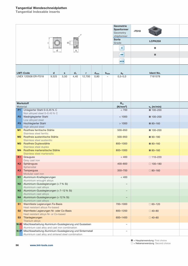
◼ = Hauptanwendung First choice
◻ = Nebenanwendung Second choice
+
+
www.lmt-tools.com56
Tangential WendeschneidplattenTangential Indexable inserts
24
l
d
r
s
d1
Geometrie SpanformerGeometrychipformer
-FS18
SorteGrade
LCPK25X
◼
◼
LMT-Code d s d1 r dmin bmin ap Ident No.LNEX 120508 ER-FS18 9,525 5,50 4,40 12,700 0,80 – 0,5–5,0 7161578
WerkstoffMaterial
Rm
(N/mm2) vc (m/min)P1 Unlegierter Stahl 0–0,45 % C
Non alloyed steel 0–0.45 % C
< 700 ◼ 100–200
P2 Niedriglegierter Stahl
Low alloyed steel
< 1000 ◼ 100–200
P3 Hochlegierter Stahl
High alloyed steel
> 1000 ◼ 80–160
M1 Rostfreie ferritische Stähle
Stainless steel ferritic
500–950 ◼ 100–200
M2 Rostfreie austenitische Stähle
Stainless steel austenitic
500–950 ◼ 90–180
M3 Rostfreie Duplexstähle
Stainless steel duplex
800–1000 ◼ 80–160
M4 Rostfreie martensitische Stähle
Stainless steel martensitic
800–1000 ◼ 80–160
K1 Grauguss
Grey cast iron
< 400 ◻ 110–220
K2 Sphäroguss
Spherodial
400–800 ◻ 100–180
K3 Temperguss
Modular cast iron
350–700 ◻ 80–160
N1 Aluminium-Knetlegierungen
Aluminium wrought alloys
< 400
N2 Aluminium-Gusslegierungen (< 7 % Si)
Aluminium cast alloys
–
N3 Aluminium-Gusslegierungen (< 7–12 % Si)
Aluminium cast alloys
–
N4 Aluminium-Gusslegierungen (> 12 % Si)
Aluminium cast alloys
–
S1 Warmfeste Legierungen Fe-Basis
Heat resistant alloys Fe-based
700–1000 ◻ 60–120
S2 Warmfeste Legierungen Ni- oder Co-Basis
Heat resistant alloys Ni- or Co-based
800–1200 ◻ 40–80
S3 Titanlegierungen
Titanium alloys
600–1400 ◻ 40–80
N K Mischbearbeitung Aluminium-Gusslegierung und Gusseisen
Aluminium cast alloy and cast iron combination
–
N P Mischbearbeitung Aluminium-Gusslegierung und Sintermetall
Aluminium cast alloy and sintered steel combination
–
+
+
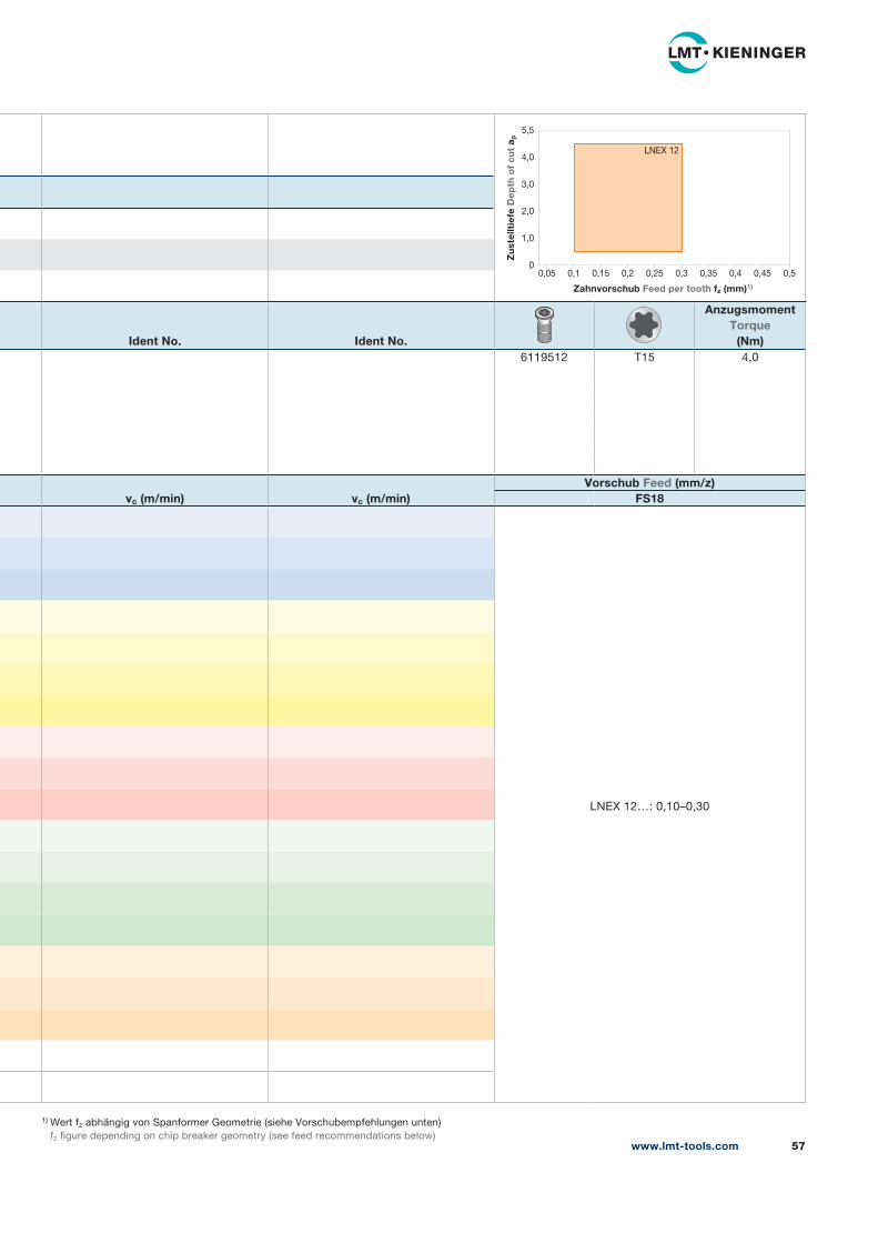
1) Wert fz abhängig von Spanformer Geometrie (siehe Vorschubempfehlungen unten)
fz figure depending on chip breaker geometry (see feed recommendations below)
Ident No. Ident No.
AnzugsmomentTorque
(Nm)6119512 T15 4,0
vc (m/min) vc (m/min)Vorschub Feed (mm/z)
FS18
LNEX 12…: 0,10–0,30
www.lmt-tools.com 57
5,5
4,0
3,0
2,0
1,0
00,05 0,1 0,15 0,2 0,25 0,3 0,35 0,4 0,45 0,5
Zahnvorschub Feed per tooth fz (mm)1)
Zu
stel
ltie
fe D
epth
of
cut
a p
LNEX 12
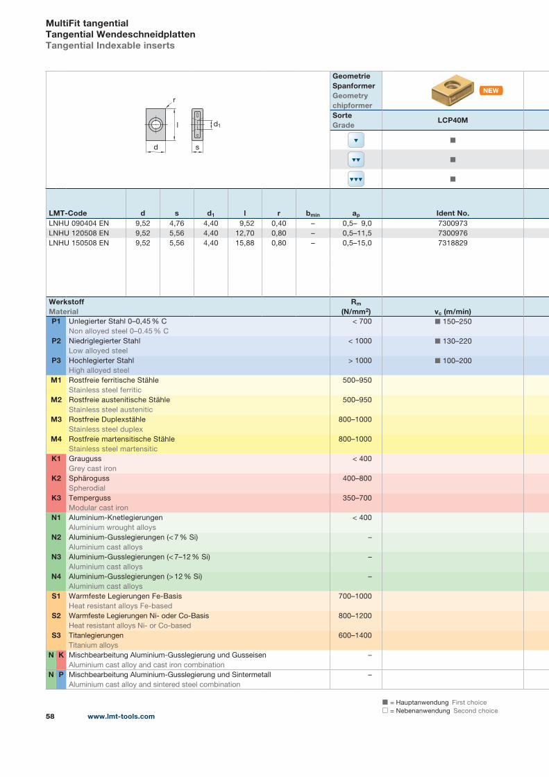
www.lmt-tools.com58
+
+
◼ = Hauptanwendung First choice
◻ = Nebenanwendung Second choice
MultiFit tangentialTangential WendeschneidplattenTangential Indexable inserts
d
r
l
s
d1
Geometrie SpanformerGeometrychipformerSorteGrade
LCP40M
◼
◼
◼
LMT-Code d s d1 l r bmin ap Ident No.LNHU 090404 EN 9,52 4,76 4,40 9,52 0,40 – 0,5– 9,0 7300973
LNHU 120508 EN 9,52 5,56 4,40 12,70 0,80 – 0,5–11,5 7300976
LNHU 150508 EN 9,52 5,56 4,40 15,88 0,80 – 0,5–15,0 7318829
WerkstoffMaterial
Rm
(N/mm2) vc (m/min)P1 Unlegierter Stahl 0–0,45 % C
Non alloyed steel 0–0.45 % C
< 700 ◼ 150–250
P2 Niedriglegierter Stahl
Low alloyed steel
< 1000 ◼ 130–220
P3 Hochlegierter Stahl
High alloyed steel
> 1000 ◼ 100–200
M1 Rostfreie ferritische Stähle
Stainless steel ferritic
500–950
M2 Rostfreie austenitische Stähle
Stainless steel austenitic
500–950
M3 Rostfreie Duplexstähle
Stainless steel duplex
800–1000
M4 Rostfreie martensitische Stähle
Stainless steel martensitic
800–1000
K1 Grauguss
Grey cast iron
< 400
K2 Sphäroguss
Spherodial
400–800
K3 Temperguss
Modular cast iron
350–700
N1 Aluminium-Knetlegierungen
Aluminium wrought alloys
< 400
N2 Aluminium-Gusslegierungen (< 7 % Si)
Aluminium cast alloys
–
N3 Aluminium-Gusslegierungen (< 7–12 % Si)
Aluminium cast alloys
–
N4 Aluminium-Gusslegierungen (> 12 % Si)
Aluminium cast alloys
–
S1 Warmfeste Legierungen Fe-Basis
Heat resistant alloys Fe-based
700–1000
S2 Warmfeste Legierungen Ni- oder Co-Basis
Heat resistant alloys Ni- or Co-based
800–1200
S3 Titanlegierungen
Titanium alloys
600–1400
N K Mischbearbeitung Aluminium-Gusslegierung und Gusseisen
Aluminium cast alloy and cast iron combination
–
N P Mischbearbeitung Aluminium-Gusslegierung und Sintermetall
Aluminium cast alloy and sintered steel combination
–
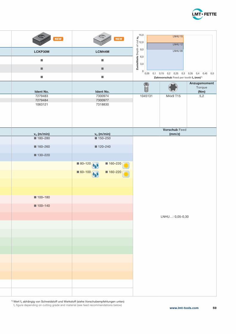
www.lmt-tools.com 59
1) Wert fz abhängig von Schneidstoff und Werkstoff (siehe Vorschubempfehlungen unten)
fz figure depending on cutting grade and material (see feed recommendations below)
LCKP30M LCM44M
◼ ◼
◼ ◼
◼ ◼
Ident No. Ident No.
AnzugsmomentTorque
(Nm)7279483 7300974 1045131 M4x9 T15 5,2
7279484 7300977
1063121 7318830
vc (m/min) vc (m/min)Vorschub Feed
(mm/z)◼ 180–280 ◼ 150–250
LNHU…: 0,05-0,30
◼ 160–260 ◼ 120–240
◼ 130–220
◼ 80–120 ◼ 160–220
◼ 60–100 ◼ 160–220
◼ 100–180
◼ 100–140
15,0
12,0
9,0
6,0
3,0
00,05 0,1 0,15 0,2 0,25 0,3 0,35 0,4 0,45 0,5
Zahnvorschub Feed per tooth fz (mm)1)
Zu
stel
ltie
fe D
epth
of
cut
a p
LNHU 09
LNHU 12
LNHU 15
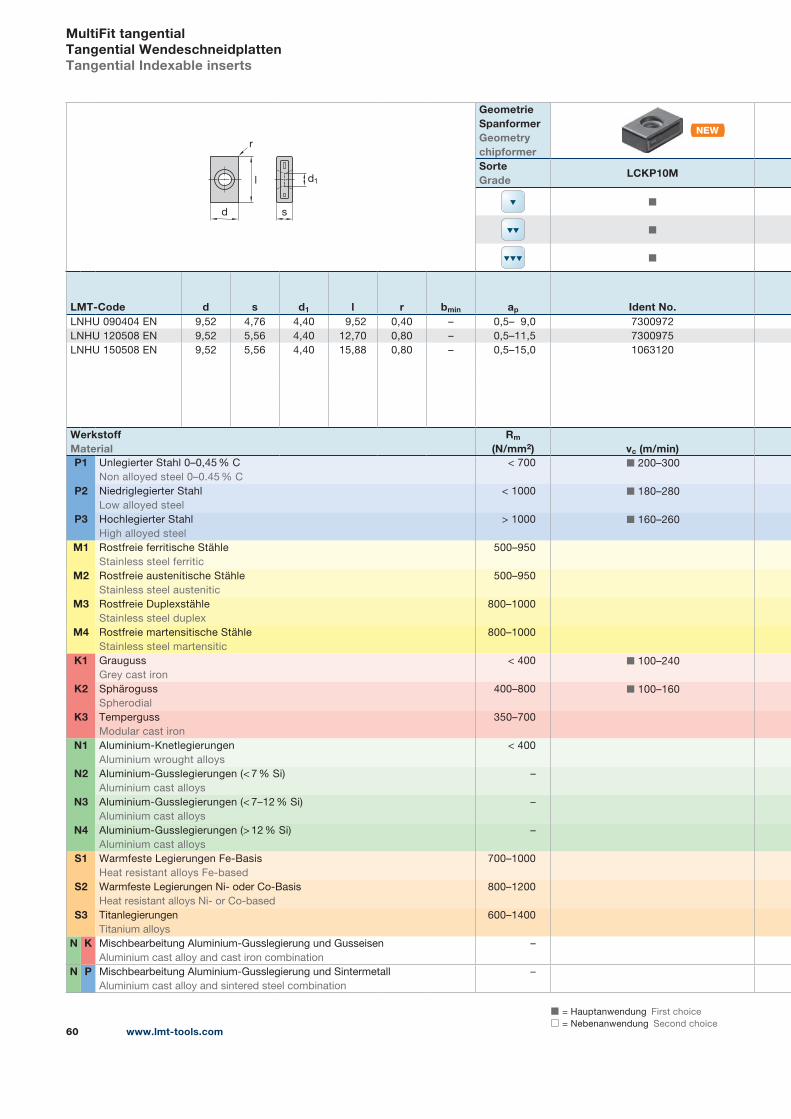
www.lmt-tools.com60
◼ = Hauptanwendung First choice
◻ = Nebenanwendung Second choice
MultiFit tangentialTangential WendeschneidplattenTangential Indexable inserts
d
r
l
s
d1
Geometrie SpanformerGeometrychipformerSorteGrade
LCKP10M
◼
◼
◼
LMT-Code d s d1 l r bmin ap Ident No.LNHU 090404 EN 9,52 4,76 4,40 9,52 0,40 – 0,5– 9,0 7300972
LNHU 120508 EN 9,52 5,56 4,40 12,70 0,80 – 0,5–11,5 7300975
LNHU 150508 EN 9,52 5,56 4,40 15,88 0,80 – 0,5–15,0 1063120
WerkstoffMaterial
Rm
(N/mm2) vc (m/min)P1 Unlegierter Stahl 0–0,45 % C
Non alloyed steel 0–0.45 % C
< 700 ◼ 200–300
P2 Niedriglegierter Stahl
Low alloyed steel
< 1000 ◼ 180–280
P3 Hochlegierter Stahl
High alloyed steel
> 1000 ◼ 160–260
M1 Rostfreie ferritische Stähle
Stainless steel ferritic
500–950
M2 Rostfreie austenitische Stähle
Stainless steel austenitic
500–950
M3 Rostfreie Duplexstähle
Stainless steel duplex
800–1000
M4 Rostfreie martensitische Stähle
Stainless steel martensitic
800–1000
K1 Grauguss
Grey cast iron
< 400 ◼ 100–240
K2 Sphäroguss
Spherodial
400–800 ◼ 100–160
K3 Temperguss
Modular cast iron
350–700
N1 Aluminium-Knetlegierungen
Aluminium wrought alloys
< 400
N2 Aluminium-Gusslegierungen (< 7 % Si)
Aluminium cast alloys
–
N3 Aluminium-Gusslegierungen (< 7–12 % Si)
Aluminium cast alloys
–
N4 Aluminium-Gusslegierungen (> 12 % Si)
Aluminium cast alloys
–
S1 Warmfeste Legierungen Fe-Basis
Heat resistant alloys Fe-based
700–1000
S2 Warmfeste Legierungen Ni- oder Co-Basis
Heat resistant alloys Ni- or Co-based
800–1200
S3 Titanlegierungen
Titanium alloys
600–1400
N K Mischbearbeitung Aluminium-Gusslegierung und Gusseisen
Aluminium cast alloy and cast iron combination
–
N P Mischbearbeitung Aluminium-Gusslegierung und Sintermetall
Aluminium cast alloy and sintered steel combination
–
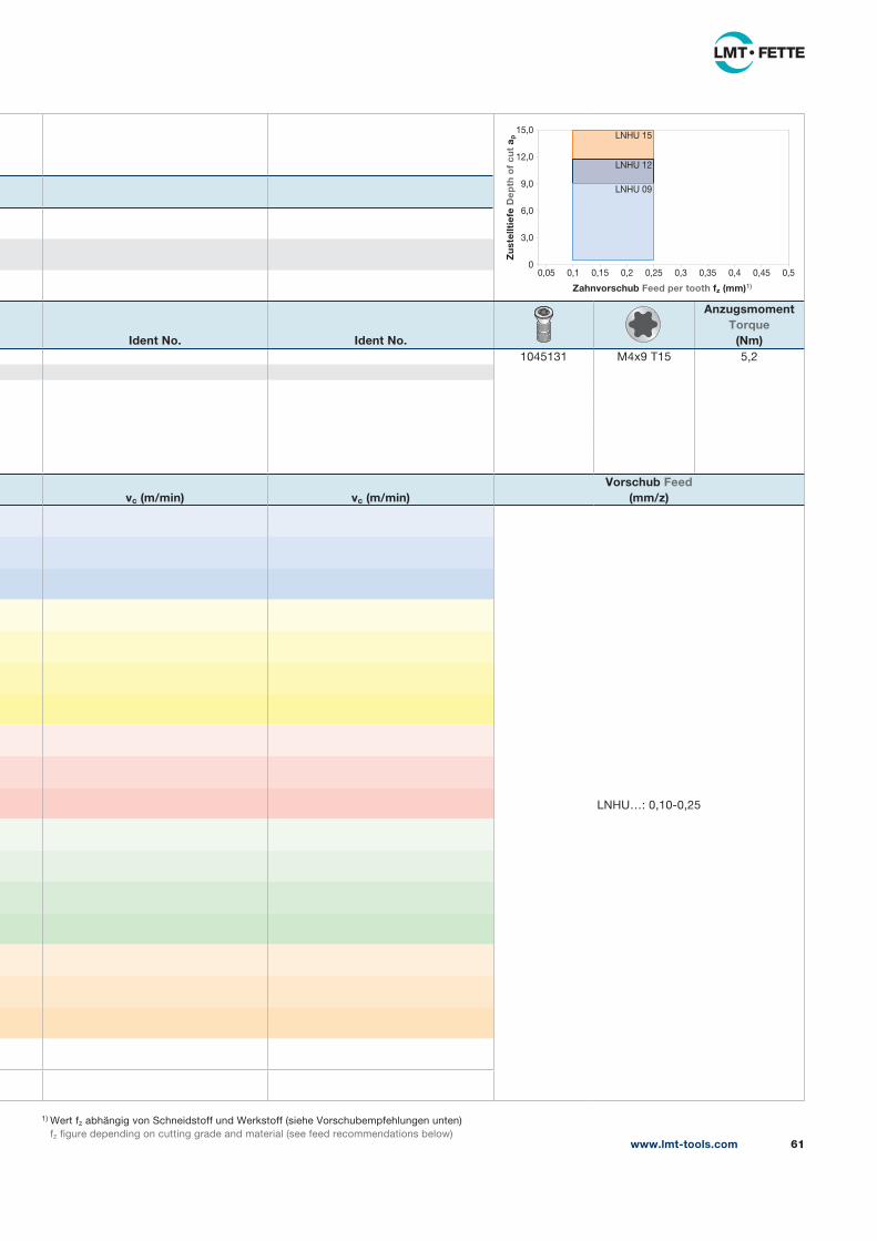
www.lmt-tools.com 61
1) Wert fz abhängig von Schneidstoff und Werkstoff (siehe Vorschubempfehlungen unten)
fz figure depending on cutting grade and material (see feed recommendations below)
Ident No. Ident No.
AnzugsmomentTorque
(Nm)1045131 M4x9 T15 5,2
vc (m/min) vc (m/min)Vorschub Feed
(mm/z)
LNHU…: 0,10-0,25
15,0
12,0
9,0
6,0
3,0
00,05 0,1 0,15 0,2 0,25 0,3 0,35 0,4 0,45 0,5
Zahnvorschub Feed per tooth fz (mm)1)
Zu
stel
ltie
fe D
epth
of
cut
a p
LNHU 09
LNHU 12
LNHU 15
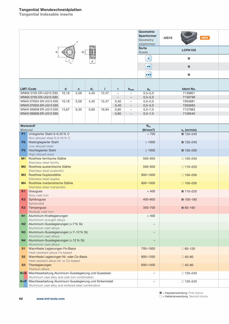
◼ = Hauptanwendung First choice
◻ = Nebenanwendung Second choice
+
+
www.lmt-tools.com62
Tangential WendeschneidplattenTangential Indexable inserts
s
d1
l
d
r
Geometrie SpanformerGeometrychipformer
-UG15
SorteGrade
LCPK15X
◼
◼
◼
LMT-Code d s d1 l r bmin ap Ident No.WNNX 0705 ER-UG15 E90 10,18 5,56 4,40 12,47 – – 0,5–5,0 7139801
WNNX 0705 ER-UG15 E80 – – 0,5–5,0 7139799
WNHX 070504 ER-UG15 E90 10,18 5,56 4,40 12,47 0,40 – 0,5–5,0 7263681
WNHX 070504 ER-UG15 E80 0,40 – 0,5–5,0 7263683
WNHX 090608 ER-UG15 E90 13,67 6,35 5,60 16,94 0,80 – 0,5–7,0 7137983
WNHX 090608 ER-UG15 E80 0,80 – 0,5–7,0 7158540
WerkstoffMaterial
Rm
(N/mm2) vc (m/min)P1 Unlegierter Stahl 0–0,45 % C
Non alloyed steel 0–0.45 % C
< 700 ◼ 120–240
P2 Niedriglegierter Stahl
Low alloyed steel
< 1000 ◼ 120–240
P3 Hochlegierter Stahl
High alloyed steel
> 1000 ◼ 100–200
M1 Rostfreie ferritische Stähle
Stainless steel ferritic
500–950 ◻ 120–240
M2 Rostfreie austenitische Stähle
Stainless steel austenitic
500–950 ◻ 110–220
M3 Rostfreie Duplexstähle
Stainless steel duplex
800–1000 ◻ 100–200
M4 Rostfreie martensitische Stähle
Stainless steel martensitic
800–1000 ◻ 100–200
K1 Grauguss
Grey cast iron
< 400 ◼ 110–220
K2 Sphäroguss
Spherodial
400–800 ◼ 100–180
K3 Temperguss
Modular cast iron
350–700 ◼ 80–160
N1 Aluminium-Knetlegierungen
Aluminium wrought alloys
< 400
N2 Aluminium-Gusslegierungen (< 7 % Si)
Aluminium cast alloys
–
N3 Aluminium-Gusslegierungen (< 7–12 % Si)
Aluminium cast alloys
–
N4 Aluminium-Gusslegierungen (> 12 % Si)
Aluminium cast alloys
–
S1 Warmfeste Legierungen Fe-Basis
Heat resistant alloys Fe-based
700–1000 ◻ 60–120
S2 Warmfeste Legierungen Ni- oder Co-Basis
Heat resistant alloys Ni- or Co-based
800–1200 ◻ 40–80
S3 Titanlegierungen
Titanium alloys
600–1400 ◻ 40–80
N K Mischbearbeitung Aluminium-Gusslegierung und Gusseisen
Aluminium cast alloy and cast iron combination
– ◻ 120–240
N P Mischbearbeitung Aluminium-Gusslegierung und Sintermetall
Aluminium cast alloy and sintered steel combination
– ◻ 120–240
+
+
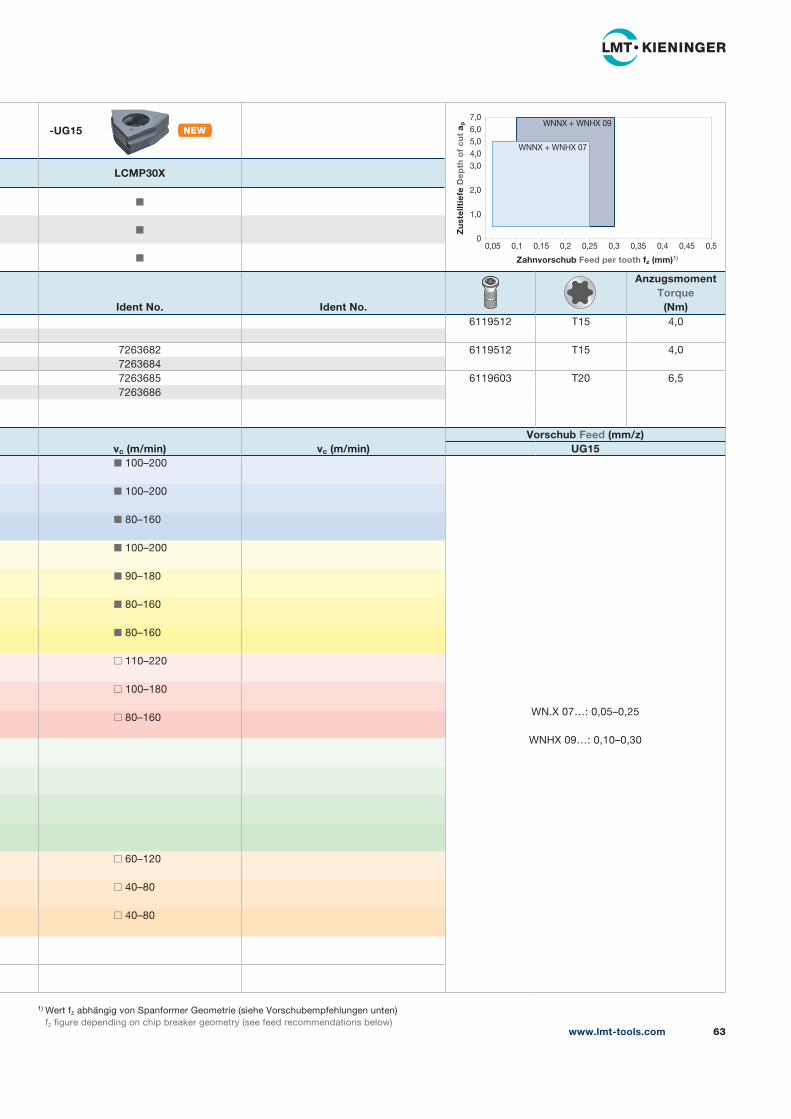
1) Wert fz abhängig von Spanformer Geometrie (siehe Vorschubempfehlungen unten)
fz figure depending on chip breaker geometry (see feed recommendations below)
-UG15
LCMP30X
◼
◼
◼
Ident No. Ident No.
AnzugsmomentTorque
(Nm)6119512 T15 4,0
7263682 6119512 T15 4,0
7263684
7263685 6119603 T20 6,5
7263686
vc (m/min) vc (m/min)Vorschub Feed (mm/z)
UG15◼ 100–200
WN.X 07…: 0,05–0,25
WNHX 09…: 0,10–0,30
◼ 100–200
◼ 80–160
◼ 100–200
◼ 90–180
◼ 80–160
◼ 80–160
◻ 110–220
◻ 100–180
◻ 80–160
◻ 60–120
◻ 40–80
◻ 40–80
www.lmt-tools.com 63
7,0
6,0
5,0
4,0
3,0
2,0
1,0
00,05 0,1 0,15 0,2 0,25 0,3 0,35 0,4 0,45 0,5
Zahnvorschub Feed per tooth fz (mm)1)
Zu
stel
ltie
fe D
epth
of
cut
a p
WNNX + WNHX 07
WNNX + WNHX 09
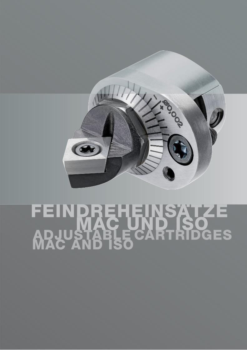
FEINDREHEINSATZE MAC UND ISOADJUSTABLE CARTRIDGES MAC AND ISO

www.lmt-tools.com 65
Feindreheinsätze MAC und ISOMicro adjustable cartridges MAC and ISO
66 Programmübersicht HaltersystemeOverview clamping systems
68 Feindreheinsätze – MACMicro adjustable cartridges – MAC
70 ISO-HalterISO Cartridges
78 BasisklemmhalterClamping holders
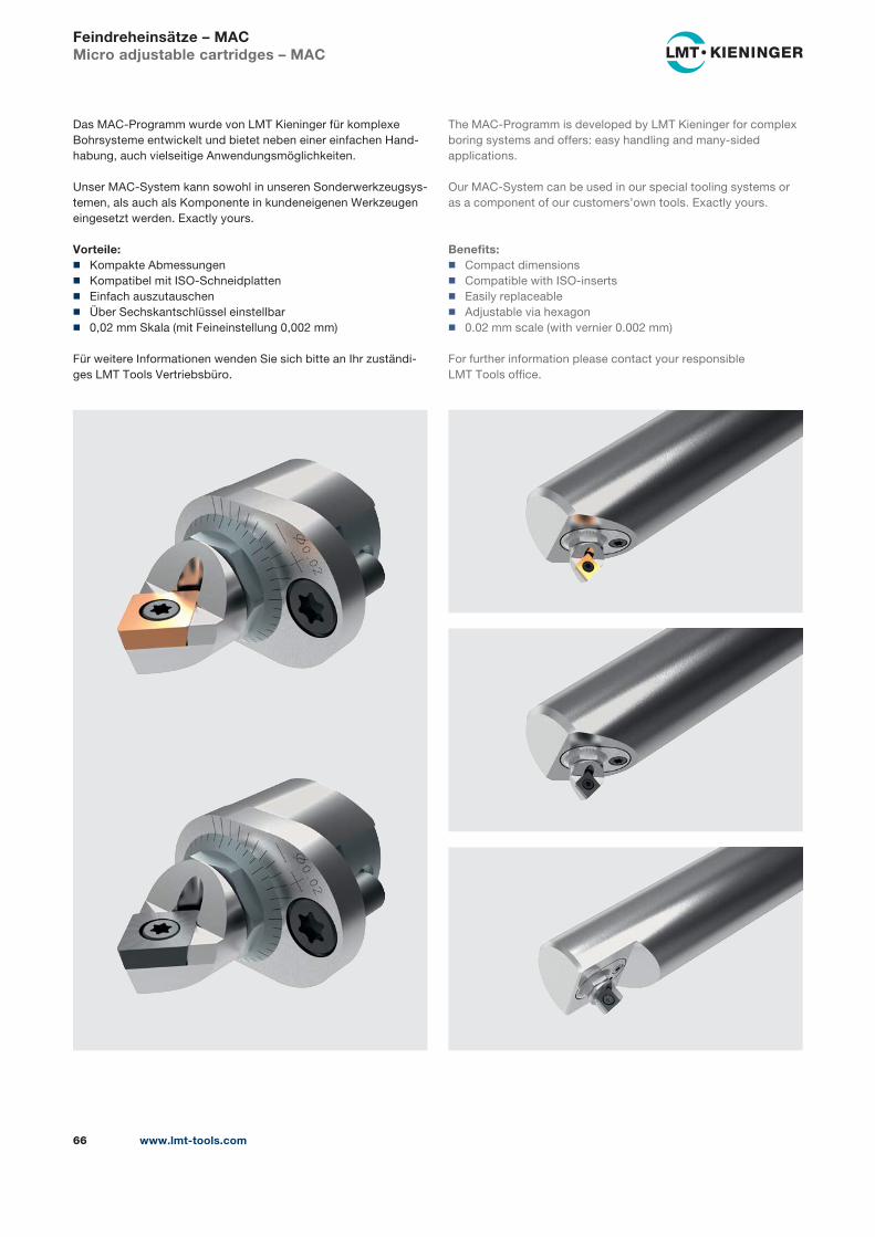
www.lmt-tools.com66
Feindreheinsätze – MACMicro adjustable cartridges – MAC
Das MAC-Programm wurde von LMT Kieninger für komplexe
Bohrsysteme entwickelt und bietet neben einer einfachen Hand-
habung, auch vielseitige Anwendungsmöglichkeiten.
Unser MAC-System kann sowohl in unseren Sonderwerkzeugsys-
temen, als auch als Komponente in kundeneigenen Werkzeugen
eingesetzt werden. Exactly yours.
Vorteile: ◼ Kompakte Abmessungen
◼ Kompatibel mit ISO-Schneidplatten
◼ Einfach auszutauschen
◼ Über Sechskantschlüssel einstellbar
◼ 0,02 mm Skala (mit Feineinstellung 0,002 mm)
Für weitere Informationen wenden Sie sich bitte an Ihr zuständi-
ges LMT Tools Vertriebsbüro.
The MAC-Programm is developed by LMT Kieninger for complex
boring systems and offers: easy handling and many-sided
applications.
Our MAC-System can be used in our special tooling systems or
as a component of our customers’own tools. Exactly yours.
Benefits: ◼ Compact dimensions
◼ Compatible with ISO-inserts
◼ Easily replaceable
◼ Adjustable via hexagon
◼ 0.02 mm scale (with vernier 0.002 mm)
For further information please contact your responsible
LMT Tools office.
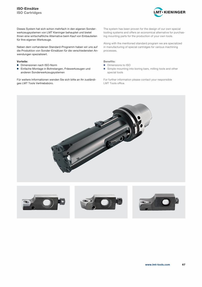
www.lmt-tools.com 67
Dieses System hat sich schon mehrfach in den eigenen Sonder-
werkzeugsystemen von LMT Kieninger behauptet und bietet
Ihnen eine wirtschaftliche Alternative beim Kauf von Einbauteilen
für Ihre eigenen Werkzeuge.
Neben dem vorhandenen Standard-Programm haben wir uns auf
die Produktion von Sonder-Einsätzen für die verschiedensten An-
wendungen spezialisiert.
Vorteile: ◼ Dimensionen nach ISO-Norm
◼ Einfache Montage in Bohrstangen, Fräswerkzeugen und
anderen Sonderwerkzeugsystemen
Für weitere Informationen wenden Sie sich bitte an Ihr zuständi-
ges LMT Tools Vertriebsbüro.
The system has been proven for the design of our own special
tooling systems and offers an economical alternative for purchas-
ing mounting parts for the production of your own tools.
Along with the mentioned standard program we are specialized
in manufacturing of special cartridges for various machining
processes.
Benefits: ◼ Dimensions to ISO
◼ Simple mounting into boring bars, milling tools and other
special tools
For further information please contact your responsible
LMT Tools office.
ISO-EinsätzeISO Cartridges
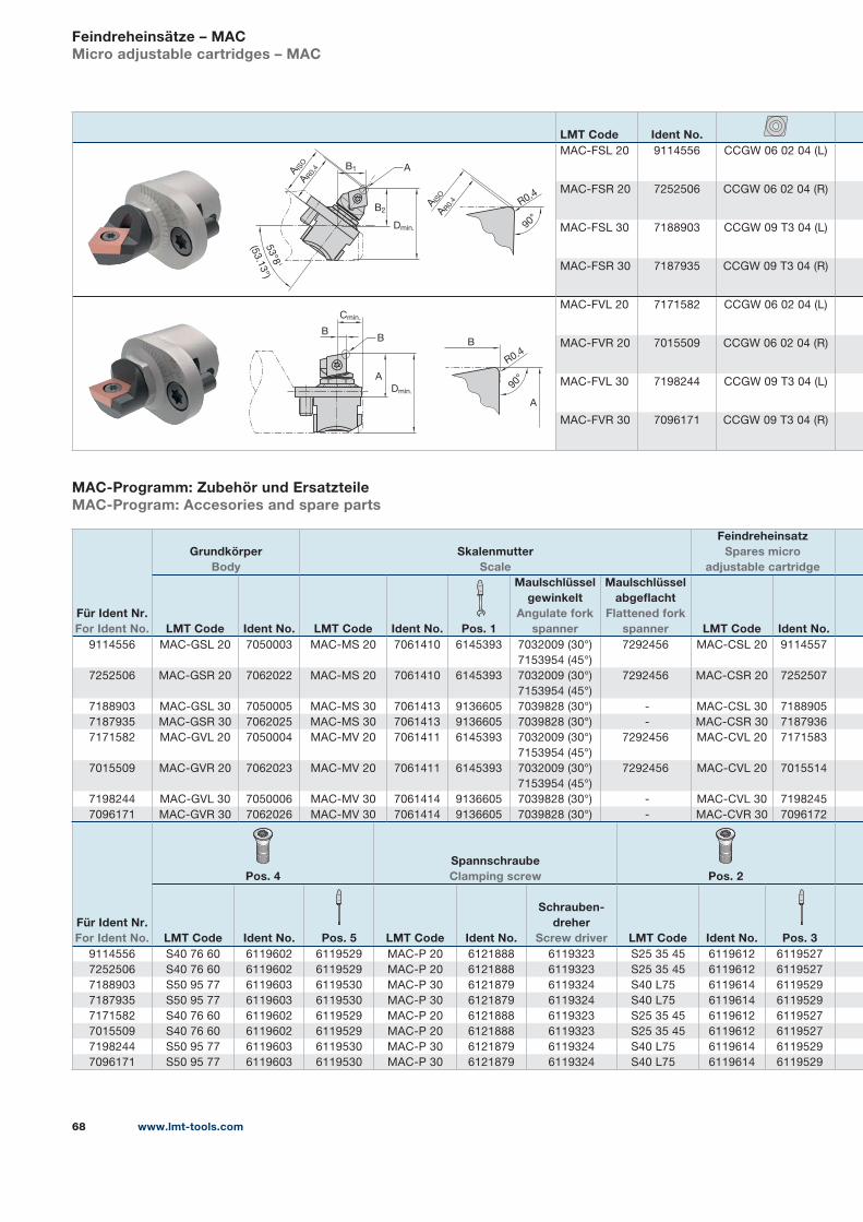
www.lmt-tools.com68
Feindreheinsätze – MACMicro adjustable cartridges – MAC
MAC-Programm: Zubehör und ErsatzteileMAC-Program: Accesories and spare parts
LMT Code Ident No.MAC-FSL 20 9114556 CCGW 06 02 04 (L)
MAC-FSR 20 7252506 CCGW 06 02 04 (R)
MAC-FSL 30 7188903 CCGW 09 T3 04 (L)
MAC-FSR 30 7187935 CCGW 09 T3 04 (R)
MAC-FVL 20 7171582 CCGW 06 02 04 (L)
MAC-FVR 20 7015509 CCGW 06 02 04 (R)
MAC-FVL 30 7198244 CCGW 09 T3 04 (L)
MAC-FVR 30 7096171 CCGW 09 T3 04 (R)
Für Ident Nr. For Ident No.
Grundkörper Body
Skalenmutter Scale
Feindreheinsatz Spares micro
adjustable cartridge
LMT Code Ident No. LMT Code Ident No.
Pos. 1
Maulschlüssel gewinkelt
Angulate fork spanner
Maulschlüssel abgeflacht
Flattened fork spanner LMT Code Ident No.
9114556 MAC-GSL 20 7050003 MAC-MS 20 7061410 6145393 7032009 (30°)
7153954 (45°)
7292456 MAC-CSL 20 9114557
7252506 MAC-GSR 20 7062022 MAC-MS 20 7061410 6145393 7032009 (30°)
7153954 (45°)
7292456 MAC-CSR 20 7252507
7188903 MAC-GSL 30 7050005 MAC-MS 30 7061413 9136605 7039828 (30°) - MAC-CSL 30 7188905
7187935 MAC-GSR 30 7062025 MAC-MS 30 7061413 9136605 7039828 (30°) - MAC-CSR 30 7187936
7171582 MAC-GVL 20 7050004 MAC-MV 20 7061411 6145393 7032009 (30°)
7153954 (45°)
7292456 MAC-CVL 20 7171583
7015509 MAC-GVR 20 7062023 MAC-MV 20 7061411 6145393 7032009 (30°)
7153954 (45°)
7292456 MAC-CVL 20 7015514
7198244 MAC-GVL 30 7050006 MAC-MV 30 7061414 9136605 7039828 (30°) - MAC-CVL 30 7198245
7096171 MAC-GVR 30 7062026 MAC-MV 30 7061414 9136605 7039828 (30°) - MAC-CVR 30 7096172
Für Ident Nr. For Ident No.
Pos. 4Spannschraube Clamping screw Pos. 2
LMT Code Ident No. Pos. 5 LMT Code Ident No.
Schrauben-dreher
Screw driver LMT Code Ident No.
Pos. 39114556 S40 76 60 6119602 6119529 MAC-P 20 6121888 6119323 S25 35 45 6119612 6119527
7252506 S40 76 60 6119602 6119529 MAC-P 20 6121888 6119323 S25 35 45 6119612 6119527
7188903 S50 95 77 6119603 6119530 MAC-P 30 6121879 6119324 S40 L75 6119614 6119529
7187935 S50 95 77 6119603 6119530 MAC-P 30 6121879 6119324 S40 L75 6119614 6119529
7171582 S40 76 60 6119602 6119529 MAC-P 20 6121888 6119323 S25 35 45 6119612 6119527
7015509 S40 76 60 6119602 6119529 MAC-P 20 6121888 6119323 S25 35 45 6119612 6119527
7198244 S50 95 77 6119603 6119530 MAC-P 30 6121879 6119324 S40 L75 6119614 6119529
7096171 S50 95 77 6119603 6119530 MAC-P 30 6121879 6119324 S40 L75 6119614 6119529
B1
53°8
'
(53.1
3°)
AA ISO
A R0,
4
Dmin.
B2
A ISO
A R0.
4 R0.4
90°
R0.4
90°
A
B
Cmin.
BB
Dmin.
A
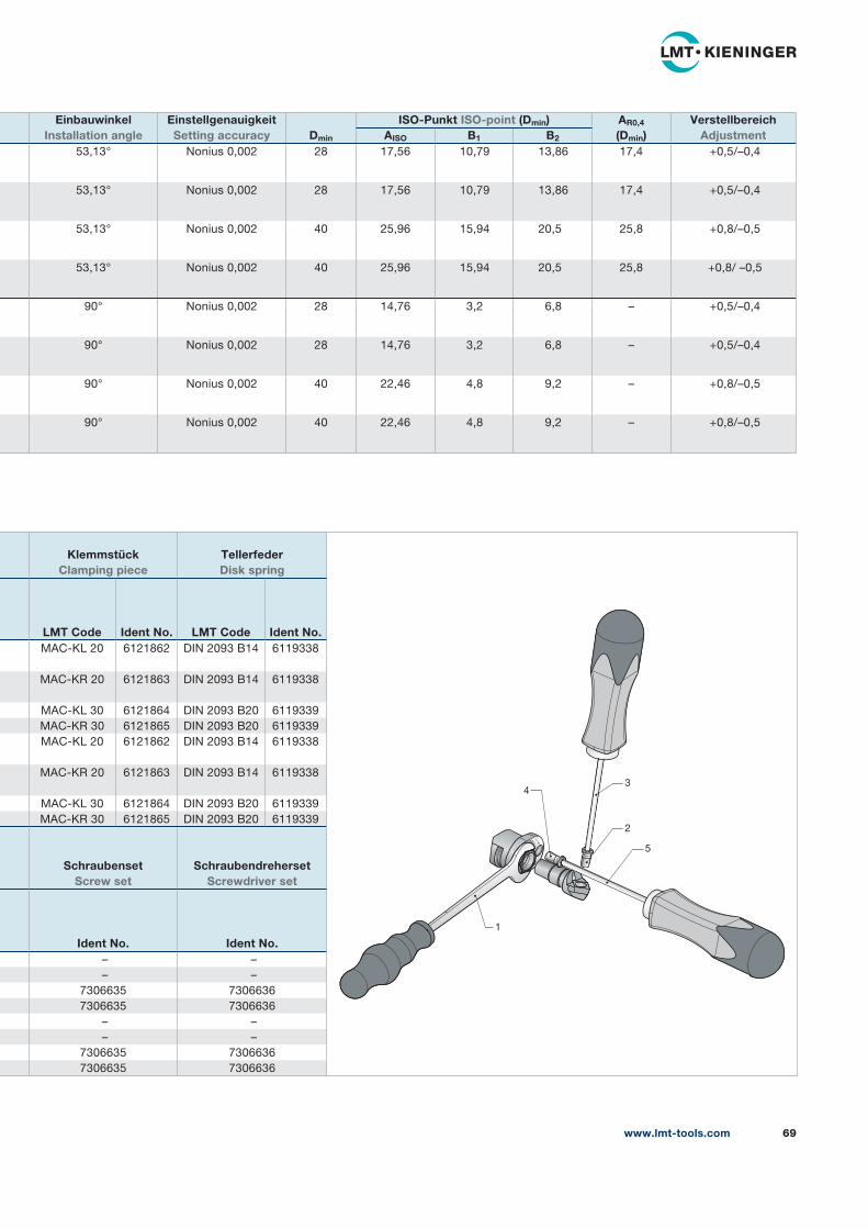
www.lmt-tools.com 69
EinbauwinkelInstallation angle
EinstellgenauigkeitSetting accuracy Dmin
ISO-Punkt ISO-point (Dmin) AR0,4
(Dmin)Verstellbereich
AdjustmentAISO B1 B2
53,13° Nonius 0,002 28 17,56 10,79 13,86 17,4 +0,5/–0,4
53,13° Nonius 0,002 28 17,56 10,79 13,86 17,4 +0,5/–0,4
53,13° Nonius 0,002 40 25,96 15,94 20,5 25,8 +0,8/–0,5
53,13° Nonius 0,002 40 25,96 15,94 20,5 25,8 +0,8/ –0,5
90° Nonius 0,002 28 14,76 3,2 6,8 – +0,5/–0,4
90° Nonius 0,002 28 14,76 3,2 6,8 – +0,5/–0,4
90° Nonius 0,002 40 22,46 4,8 9,2 – +0,8/–0,5
90° Nonius 0,002 40 22,46 4,8 9,2 – +0,8/–0,5
Klemmstück Clamping piece
Tellerfeder Disk spring
LMT Code Ident No. LMT Code Ident No.MAC-KL 20 6121862 DIN 2093 B14 6119338
MAC-KR 20 6121863 DIN 2093 B14 6119338
MAC-KL 30 6121864 DIN 2093 B20 6119339
MAC-KR 30 6121865 DIN 2093 B20 6119339
MAC-KL 20 6121862 DIN 2093 B14 6119338
MAC-KR 20 6121863 DIN 2093 B14 6119338
MAC-KL 30 6121864 DIN 2093 B20 6119339
MAC-KR 30 6121865 DIN 2093 B20 6119339
SchraubensetScrew set
SchraubendrehersetScrewdriver set
Ident No. Ident No. – –
– –
7306635 7306636
7306635 7306636
– –
– –
7306635 7306636
7306635 7306636
– +
2
1
5
34
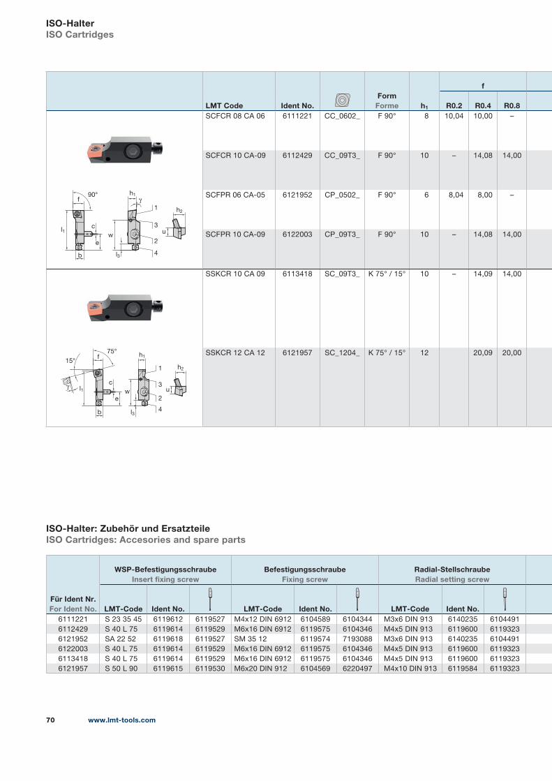
www.lmt-tools.com70
LMT Code Ident No.Form
Forme h1
f
R0.2 R0.4 R0.8SCFCR 08 CA 06 6111221 CC_0602_ F 90° 8 10,04 10,00 –
SCFCR 10 CA-09 6112429 CC_09T3_ F 90° 10 – 14,08 14,00
SCFPR 06 CA-05 6121952 CP_0502_ F 90° 6 8,04 8,00 –
SCFPR 10 CA-09 6122003 CP_09T3_ F 90° 10 – 14,08 14,00
SSKCR 10 CA 09 6113418 SC_09T3_ K 75° / 15° 10 – 14,09 14,00
SSKCR 12 CA 12 6121957 SC_1204_ K 75° / 15° 12 20,09 20,00
ISO-HalterISO Cartridges
ISO-Halter: Zubehör und ErsatzteileISO Cartridges: Accesories and spare parts
90°
l1
h2
uc
e
b
f
l3
w
1
2
3
4
h1
γ
w
l3
l1
h1
h2
u
b
1
2
3
4
75°
15°f
γ
e
c
Für Ident Nr. For Ident No.
WSP-Befestigungsschraube Insert fixing screw
Befestigungsschraube Fixing screw
Radial-Stellschraube Radial setting screw
LMT-Code Ident No. LMT-Code Ident No. LMT-Code Ident No.6111221 S 23 35 45 6119612 6119527 M4x12 DIN 6912 6104589 6104344 M3x6 DIN 913 6140235 6104491
6112429 S 40 L 75 6119614 6119529 M6x16 DIN 6912 6119575 6104346 M4x5 DIN 913 6119600 6119323
6121952 SA 22 52 6119618 6119527 SM 35 12 6119574 7193088 M3x6 DIN 913 6140235 6104491
6122003 S 40 L 75 6119614 6119529 M6x16 DIN 6912 6119575 6104346 M4x5 DIN 913 6119600 6119323
6113418 S 40 L 75 6119614 6119529 M6x16 DIN 6912 6119575 6104346 M4x5 DIN 913 6119600 6119323
6121957 S 50 L 90 6119615 6119530 M6x20 DIN 912 6104569 6220497 M4x10 DIN 913 6119584 6119323
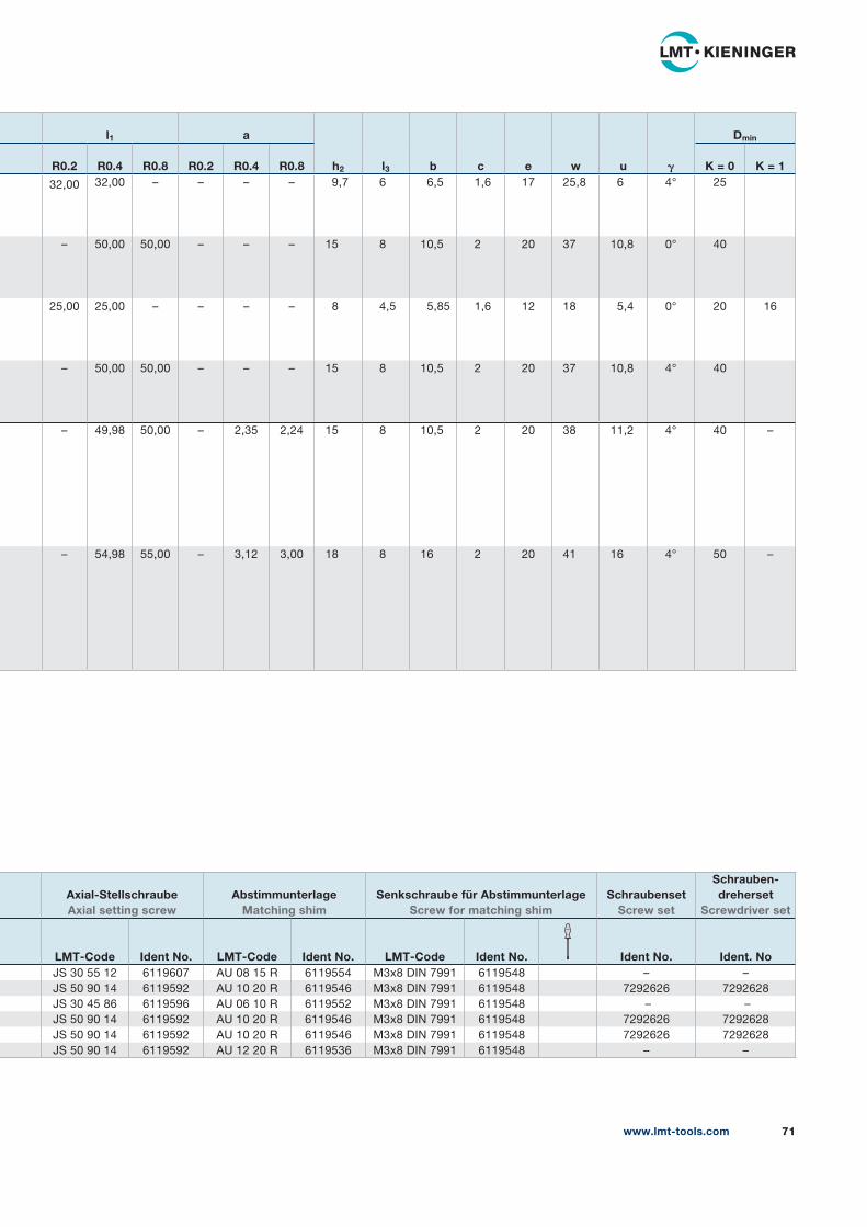
www.lmt-tools.com 71
l1 a
h2 l3 b c e w u 𝛄
Dmin
R0.2 R0.4 R0.8 R0.2 R0.4 R0.8 K = 0 K = 1
32,00 32,00 – – – – 9,7 6 6,5 1,6 17 25,8 6 4° 25
– 50,00 50,00 – – – 15 8 10,5 2 20 37 10,8 0° 40
25,00 25,00 – – – – 8 4,5 5,85 1,6 12 18 5,4 0° 20 16
– 50,00 50,00 – – – 15 8 10,5 2 20 37 10,8 4° 40
– 49,98 50,00 – 2,35 2,24 15 8 10,5 2 20 38 11,2 4° 40 –
– 54,98 55,00 – 3,12 3,00 18 8 16 2 20 41 16 4° 50 –
Axial-Stellschraube Axial setting screw
Abstimmunterlage Matching shim
Senkschraube für Abstimmunterlage Screw for matching shim
SchraubensetScrew set
Schrauben-dreherset
Screwdriver set
LMT-Code Ident No. LMT-Code Ident No. LMT-Code Ident No. Ident No. Ident. NoJS 30 55 12 6119607 AU 08 15 R 6119554 M3x8 DIN 7991 6119548 – –
JS 50 90 14 6119592 AU 10 20 R 6119546 M3x8 DIN 7991 6119548 7292626 7292628
JS 30 45 86 6119596 AU 06 10 R 6119552 M3x8 DIN 7991 6119548 – –
JS 50 90 14 6119592 AU 10 20 R 6119546 M3x8 DIN 7991 6119548 7292626 7292628
JS 50 90 14 6119592 AU 10 20 R 6119546 M3x8 DIN 7991 6119548 7292626 7292628
JS 50 90 14 6119592 AU 12 20 R 6119536 M3x8 DIN 7991 6119548 – –
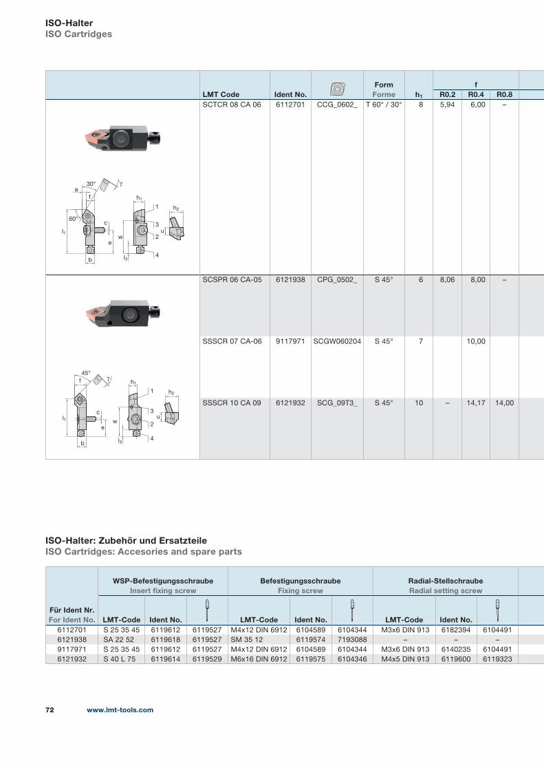
www.lmt-tools.com72
LMT Code Ident No.Form
Forme h1
fR0.2 R0.4 R0.8
SCTCR 08 CA 06 6112701 CCG_0602_ T 60° / 30° 8 5,94 6,00 –
SCSPR 06 CA-05 6121938 CPG_0502_ S 45° 6 8,06 8,00 –
SSSCR 07 CA-06 9117971 SCGW060204 S 45° 7 10,00
SSSCR 10 CA 09 6121932 SCG_09T3_ S 45° 10 – 14,17 14,00
ISO-HalterISO Cartridges
ISO-Halter: Zubehör und ErsatzteileISO Cartridges: Accesories and spare parts
1
2
3
4
h1
b l3
γ
e
c
l1
60°
w
30°
u
h2
a
f
1
2
3
4l3
w
h2
u
γ
l1
45°
b
c
e
f h1
Für Ident Nr. For Ident No.
WSP-Befestigungsschraube Insert fixing screw
Befestigungsschraube Fixing screw
Radial-Stellschraube Radial setting screw
LMT-Code Ident No. LMT-Code Ident No. LMT-Code Ident No.6112701 S 25 35 45 6119612 6119527 M4x12 DIN 6912 6104589 6104344 M3x6 DIN 913 6182394 6104491
6121938 SA 22 52 6119618 6119527 SM 35 12 6119574 7193088 – – –
9117971 S 25 35 45 6119612 6119527 M4x12 DIN 6912 6104589 6104344 M3x6 DIN 913 6140235 6104491
6121932 S 40 L 75 6119614 6119529 M6x16 DIN 6912 6119575 6104346 M4x5 DIN 913 6119600 6119323
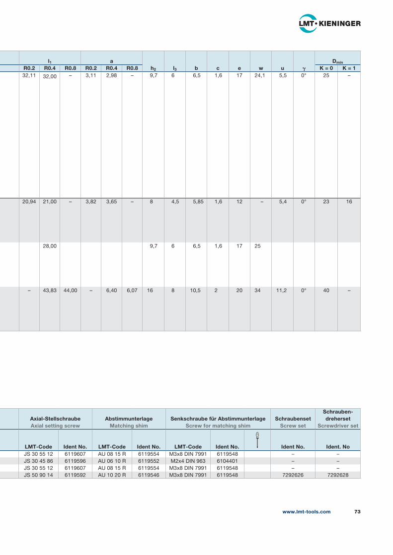
www.lmt-tools.com 73
l1 ah2 l3 b c e w u 𝛄
Dmin
R0.2 R0.4 R0.8 R0.2 R0.4 R0.8 K = 0 K = 132,11 32,00 – 3,11 2,98 – 9,7 6 6,5 1,6 17 24,1 5,5 0° 25 –
20,94 21,00 – 3,82 3,65 – 8 4,5 5,85 1,6 12 – 5,4 0° 23 16
28,00 9,7 6 6,5 1,6 17 25
– 43,83 44,00 – 6,40 6,07 16 8 10,5 2 20 34 11,2 0° 40 –
Axial-Stellschraube Axial setting screw
Abstimmunterlage Matching shim
Senkschraube für Abstimmunterlage Screw for matching shim
SchraubensetScrew set
Schrauben-dreherset
Screwdriver set
LMT-Code Ident No. LMT-Code Ident No. LMT-Code Ident No. Ident No. Ident. NoJS 30 55 12 6119607 AU 08 15 R 6119554 M3x8 DIN 7991 6119548 – –
JS 30 45 86 6119596 AU 06 10 R 6119552 M2x4 DIN 963 6104401 – –
JS 30 55 12 6119607 AU 08 15 R 6119554 M3x8 DIN 7991 6119548 – –
JS 50 90 14 6119592 AU 10 20 R 6119546 M3x8 DIN 7991 6119548 7292626 7292628
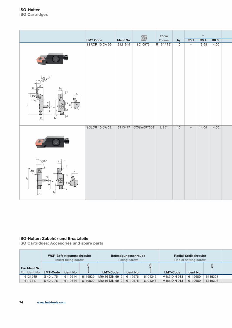
www.lmt-tools.com74
LMT Code Ident No.Form
Forme h1
fR0.2 R0.4 R0.8
SSRCR 10 CA 09 6121945 SC_09T3_ R 15° / 75° 10 – 13,98 14,00
SCLCR 10 CA 09 6113417 CCGW09T308 L 95° 10 – 14,04 14,00
ISO-HalterISO Cartridges
ISO-Halter: Zubehör und ErsatzteileISO Cartridges: Accesories and spare parts
Für Ident Nr. For Ident No.
WSP-Befestigungsschraube Insert fixing screw
Befestigungsschraube Fixing screw
Radial-Stellschraube Radial setting screw
LMT-Code Ident No. LMT-Code Ident No. LMT-Code Ident No.6121945 S 40 L 75 6119614 6119529 M6x16 DIN 6912 6119575 6104346 M4x5 DIN 913 6119600 6119323
6113417 S 40 L 75 6119614 6119529 M6x16 DIN 6912 6119575 6104346 M4x5 DIN 913 6119600 6119323
c
e
b
l1
75°
u
h2
γ
15°
1
2
3
4
w
l3
h1a
f
l1
h2
95°
95°
l3
h1
e
c
f
b
u
1
2
3
4
w
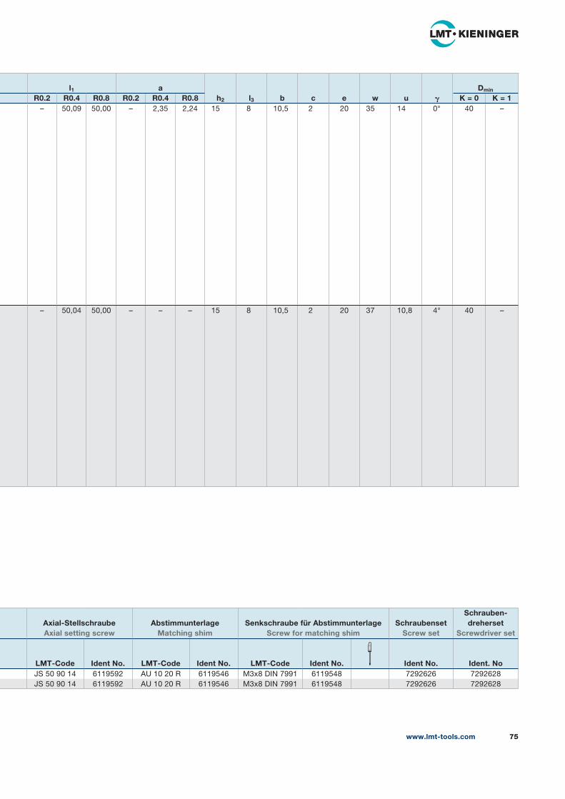
www.lmt-tools.com 75
l1 ah2 l3 b c e w u 𝛄
Dmin
R0.2 R0.4 R0.8 R0.2 R0.4 R0.8 K = 0 K = 1– 50,09 50,00 – 2,35 2,24 15 8 10,5 2 20 35 14 0° 40 –
– 50,04 50,00 – – – 15 8 10,5 2 20 37 10,8 4° 40 –
Axial-Stellschraube Axial setting screw
Abstimmunterlage Matching shim
Senkschraube für Abstimmunterlage Screw for matching shim
SchraubensetScrew set
Schrauben-dreherset
Screwdriver set
LMT-Code Ident No. LMT-Code Ident No. LMT-Code Ident No. Ident No. Ident. NoJS 50 90 14 6119592 AU 10 20 R 6119546 M3x8 DIN 7991 6119548 7292626 7292628
JS 50 90 14 6119592 AU 10 20 R 6119546 M3x8 DIN 7991 6119548 7292626 7292628
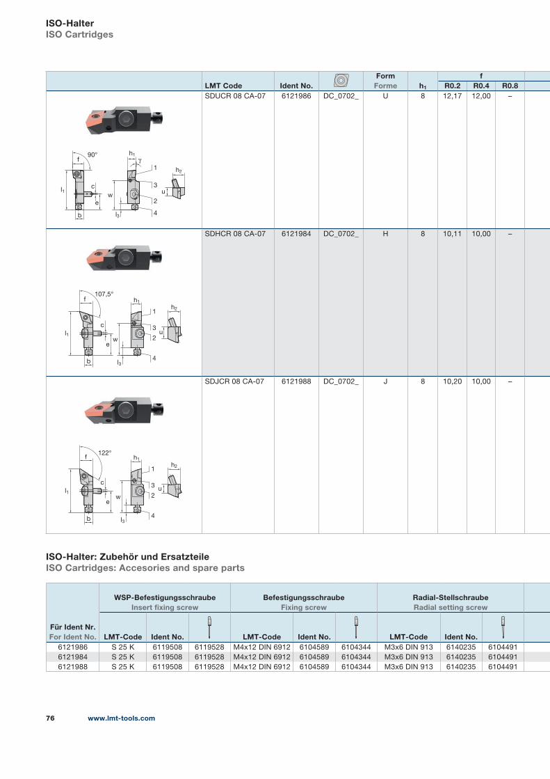
www.lmt-tools.com76
LMT Code Ident No.Form
Forme h1
fR0.2 R0.4 R0.8
SDUCR 08 CA-07 6121986 DC_0702_ U 8 12,17 12,00 –
SDHCR 08 CA-07 6121984 DC_0702_ H 8 10,11 10,00 –
SDJCR 08 CA-07 6121988 DC_0702_ J 8 10,20 10,00 –
ISO-HalterISO Cartridges
ISO-Halter: Zubehör und ErsatzteileISO Cartridges: Accesories and spare parts
90°
l1
h2
uc
e
b
f
l3
w
1
2
3
4
h1
γ
c
e
u
h2
h1
1
2
3
4
w
l3b
122°
l1
f
c
e
u
h2
h1
1
2
3
4
w
l3
107,5°
l1
b
f
Für Ident Nr. For Ident No.
WSP-Befestigungsschraube Insert fixing screw
Befestigungsschraube Fixing screw
Radial-Stellschraube Radial setting screw
LMT-Code Ident No. LMT-Code Ident No. LMT-Code Ident No.6121986 S 25 K 6119508 6119528 M4x12 DIN 6912 6104589 6104344 M3x6 DIN 913 6140235 6104491
6121984 S 25 K 6119508 6119528 M4x12 DIN 6912 6104589 6104344 M3x6 DIN 913 6140235 6104491
6121988 S 25 K 6119508 6119528 M4x12 DIN 6912 6104589 6104344 M3x6 DIN 913 6140235 6104491
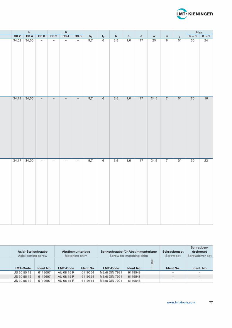
www.lmt-tools.com 77
l1 ah2 l3 b c e w u 𝛄
Dmin
R0.2 R0.4 R0.8 R0.2 R0.4 R0.8 K = 0 K = 134,02 34,00 – – – – 9,7 6 6,5 1,6 17 25 9 0° 30 24
34,11 34,00 – – – – 9,7 6 6,5 1,6 17 24,5 7 0° 20 16
34,17 34,00 – – – – 9,7 6 6,5 1,6 17 24,5 7 0° 30 22
Axial-Stellschraube Axial setting screw
Abstimmunterlage Matching shim
Senkschraube für Abstimmunterlage Screw for matching shim
SchraubensetScrew set
Schrauben-dreherset
Screwdriver set
LMT-Code Ident No. LMT-Code Ident No. LMT-Code Ident No. Ident No. Ident. NoJS 30 55 12 6119607 AU 08 15 R 6119554 M3x8 DIN 7991 6119548 – –
JS 30 55 12 6119607 AU 08 15 R 6119554 M3x8 DIN 7991 6119548 – –
JS 30 55 12 6119607 AU 08 15 R 6119554 M3x8 DIN 7991 6119548 – –
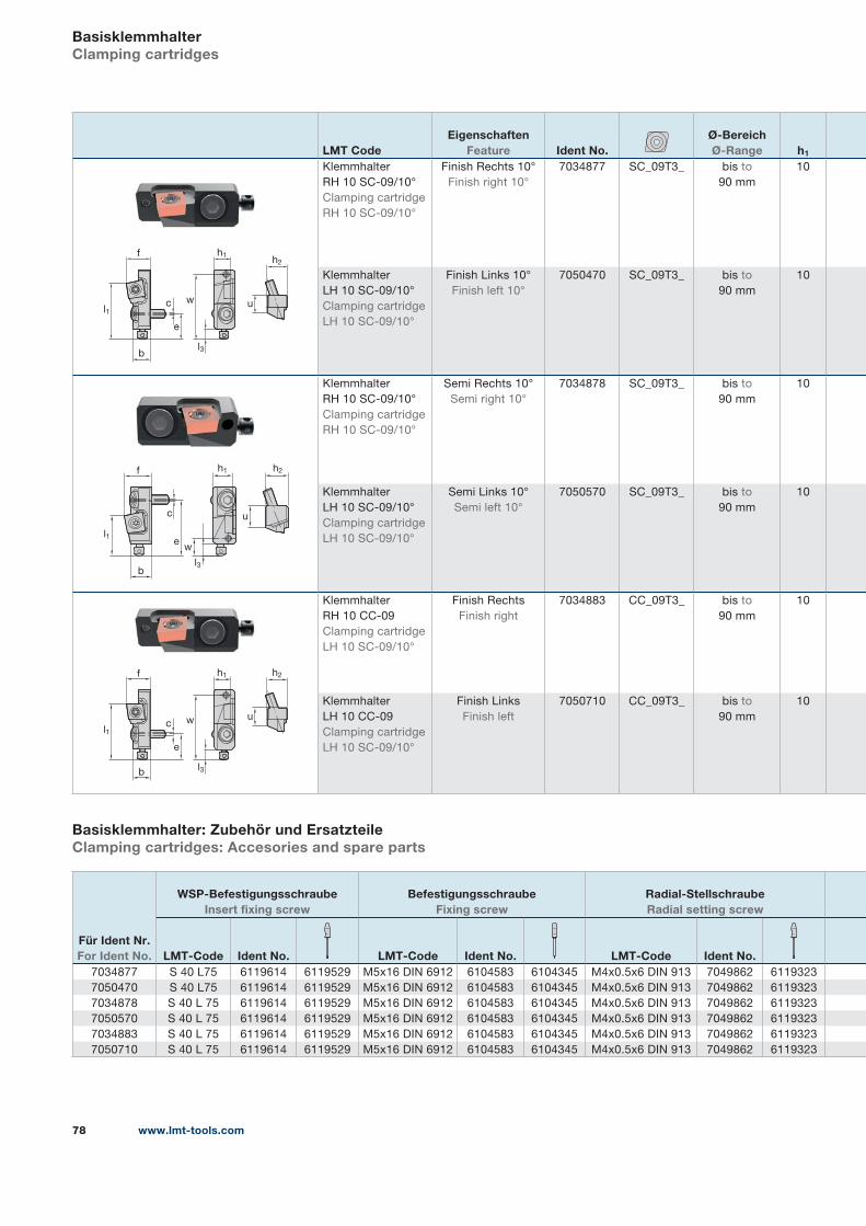
www.lmt-tools.com78
LMT CodeEigenschaften
Feature Ident No.Ø-Bereich Ø-Range h1
Klemmhalter
RH 10 SC-09/10°
Clamping cartridge
RH 10 SC-09/10°
Finish Rechts 10°
Finish right 10°
7034877 SC_09T3_ bis to
90 mm
10
Klemmhalter
LH 10 SC-09/10°
Clamping cartridge
LH 10 SC-09/10°
Finish Links 10°
Finish left 10°
7050470 SC_09T3_ bis to
90 mm
10
Klemmhalter
RH 10 SC-09/10°
Clamping cartridge
RH 10 SC-09/10°
Semi Rechts 10°
Semi right 10°
7034878 SC_09T3_ bis to
90 mm
10
Klemmhalter
LH 10 SC-09/10°
Clamping cartridge
LH 10 SC-09/10°
Semi Links 10°
Semi left 10°
7050570 SC_09T3_ bis to
90 mm
10
Klemmhalter
RH 10 CC-09
Clamping cartridge
LH 10 SC-09/10°
Finish Rechts
Finish right
7034883 CC_09T3_ bis to
90 mm
10
Klemmhalter
LH 10 CC-09
Clamping cartridge
LH 10 SC-09/10°
Finish Links
Finish left
7050710 CC_09T3_ bis to
90 mm
10
BasisklemmhalterClamping cartridges
Basisklemmhalter: Zubehör und ErsatzteileClamping cartridges: Accesories and spare parts
Für Ident Nr. For Ident No.
WSP-Befestigungsschraube Insert fixing screw
Befestigungsschraube Fixing screw
Radial-Stellschraube Radial setting screw
LMT-Code Ident No. LMT-Code Ident No. LMT-Code Ident No.7034877 S 40 L75 6119614 6119529 M5x16 DIN 6912 6104583 6104345 M4x0.5x6 DIN 913 7049862 6119323
7050470 S 40 L75 6119614 6119529 M5x16 DIN 6912 6104583 6104345 M4x0.5x6 DIN 913 7049862 6119323
7034878 S 40 L 75 6119614 6119529 M5x16 DIN 6912 6104583 6104345 M4x0.5x6 DIN 913 7049862 6119323
7050570 S 40 L 75 6119614 6119529 M5x16 DIN 6912 6104583 6104345 M4x0.5x6 DIN 913 7049862 6119323
7034883 S 40 L 75 6119614 6119529 M5x16 DIN 6912 6104583 6104345 M4x0.5x6 DIN 913 7049862 6119323
7050710 S 40 L 75 6119614 6119529 M5x16 DIN 6912 6104583 6104345 M4x0.5x6 DIN 913 7049862 6119323
c
e
u
h2
h1
w
bl3
l1
f
c
e
u
h2h1
w
bl3
l1
f
c
e
u
h2h1
w
bl3
l1
f
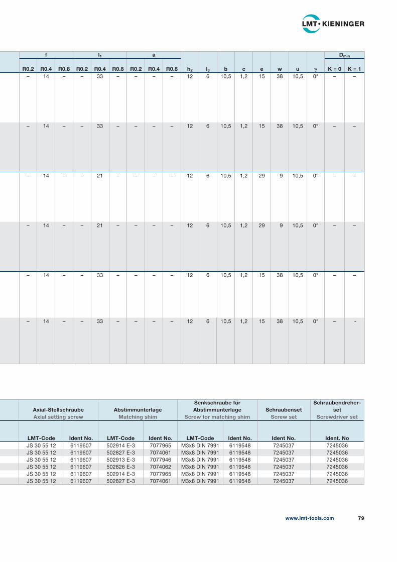
www.lmt-tools.com 79
f l1 a
h2 l3 b c e w u 𝛄
Dmin
R0.2 R0.4 R0.8 R0.2 R0.4 R0.8 R0.2 R0.4 R0.8 K = 0 K = 1– 14 – – 33 – – – – 12 6 10,5 1,2 15 38 10,5 0° – –
– 14 – – 33 – – – – 12 6 10,5 1,2 15 38 10,5 0° – –
– 14 – – 21 – – – – 12 6 10,5 1,2 29 9 10,5 0° – –
– 14 – – 21 – – – – 12 6 10,5 1,2 29 9 10,5 0° – –
– 14 – – 33 – – – – 12 6 10,5 1,2 15 38 10,5 0° – –
– 14 – – 33 – – – – 12 6 10,5 1,2 15 38 10,5 0° – -
Axial-Stellschraube Axial setting screw
Abstimmunterlage Matching shim
Senkschraube für Abstimmunterlage
Screw for matching shimSchraubenset
Screw set
Schraubendreher-set
Screwdriver set
LMT-Code Ident No. LMT-Code Ident No. LMT-Code Ident No. Ident No. Ident. NoJS 30 55 12 6119607 502914 E-3 7077965 M3x8 DIN 7991 6119548 7245037 7245036
JS 30 55 12 6119607 502827 E-3 7074061 M3x8 DIN 7991 6119548 7245037 7245036
JS 30 55 12 6119607 502913 E-3 7077946 M3x8 DIN 7991 6119548 7245037 7245036
JS 30 55 12 6119607 502826 E-3 7074062 M3x8 DIN 7991 6119548 7245037 7245036
JS 30 55 12 6119607 502914 E-3 7077965 M3x8 DIN 7991 6119548 7245037 7245036
JS 30 55 12 6119607 502827 E-3 7074061 M3x8 DIN 7991 6119548 7245037 7245036
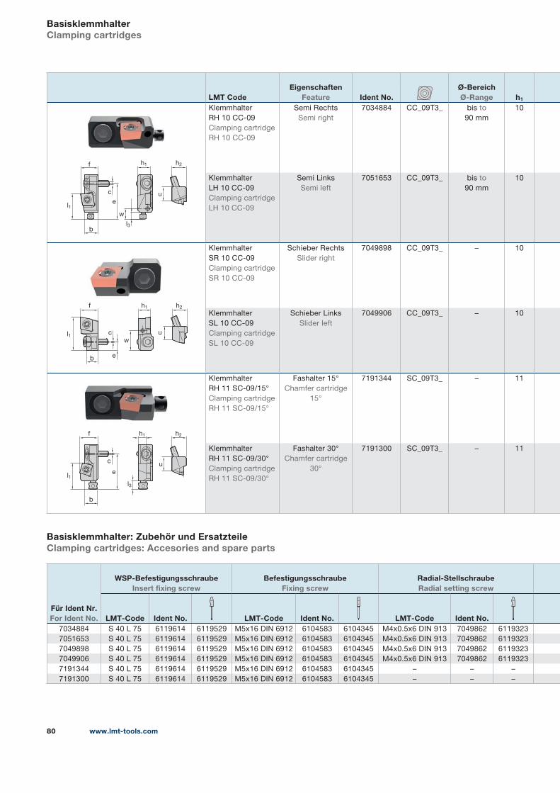
www.lmt-tools.com80
LMT CodeEigenschaften
Feature Ident No.Ø-Bereich Ø-Range h1
Klemmhalter
RH 10 CC-09
Clamping cartridge
RH 10 CC-09
Semi Rechts
Semi right
7034884 CC_09T3_ bis to
90 mm
10
Klemmhalter
LH 10 CC-09
Clamping cartridge
LH 10 CC-09
Semi Links
Semi left
7051653 CC_09T3_ bis to
90 mm
10
Klemmhalter
SR 10 CC-09
Clamping cartridge
SR 10 CC-09
Schieber Rechts
Slider right
7049898 CC_09T3_ – 10
Klemmhalter
SL 10 CC-09
Clamping cartridge
SL 10 CC-09
Schieber Links
Slider left
7049906 CC_09T3_ – 10
Klemmhalter
RH 11 SC-09/15°
Clamping cartridge
RH 11 SC-09/15°
Fashalter 15°
Chamfer cartridge
15°
7191344 SC_09T3_ – 11
Klemmhalter
RH 11 SC-09/30°
Clamping cartridge
RH 11 SC-09/30°
Fashalter 30°
Chamfer cartridge
30°
7191300 SC_09T3_ – 11
BasisklemmhalterClamping cartridges
Basisklemmhalter: Zubehör und ErsatzteileClamping cartridges: Accesories and spare parts
Für Ident Nr. For Ident No.
WSP-Befestigungsschraube Insert fixing screw
Befestigungsschraube Fixing screw
Radial-Stellschraube Radial setting screw
LMT-Code Ident No. LMT-Code Ident No. LMT-Code Ident No.7034884 S 40 L 75 6119614 6119529 M5x16 DIN 6912 6104583 6104345 M4x0.5x6 DIN 913 7049862 6119323
7051653 S 40 L 75 6119614 6119529 M5x16 DIN 6912 6104583 6104345 M4x0.5x6 DIN 913 7049862 6119323
7049898 S 40 L 75 6119614 6119529 M5x16 DIN 6912 6104583 6104345 M4x0.5x6 DIN 913 7049862 6119323
7049906 S 40 L 75 6119614 6119529 M5x16 DIN 6912 6104583 6104345 M4x0.5x6 DIN 913 7049862 6119323
7191344 S 40 L 75 6119614 6119529 M5x16 DIN 6912 6104583 6104345 – – –
7191300 S 40 L 75 6119614 6119529 M5x16 DIN 6912 6104583 6104345 – – –
c
eu
h2h1
w
bl3
l1
f
l1
h2f
c
e
u
w
b
h1
c
eu
h2h1
b
l3
l1
f
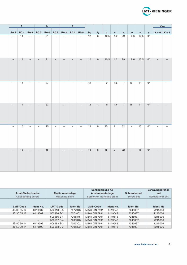
www.lmt-tools.com 81
f l1 a
h2 l3 b c e w u 𝛄
Dmin
R0.2 R0.4 R0.8 R0.2 R0.4 R0.8 R0.2 R0.4 R0.8 K = 0 K = 1– 14 – – 21 – – – – 12 6 10,5 1,2 29 8,6 10,5 0° – –
– 14 – – 21 – – – – 12 6 10,5 1,2 29 8,6 10,5 0° – –
– 14 – – 27 – – – – 12 – 9 1,6 7 16 11 0° – –
– 14 – – 27 – – – – 12 – 9 1,6 7 16 11 0° – –
– 16 – – 15 – – – – 13 8 15 2 32 – 15 0° – –
– 16 – – 15 – – – – 13 8 15 2 32 – 15 0° – –
Axial-Stellschraube Axial setting screw
Abstimmunterlage Matching shim
Senkschraube für Abstimmunterlage
Screw for matching shimSchraubenset
Screw set
Schraubendreher-set
Screwdriver set
LMT-Code Ident No. LMT-Code Ident No. LMT-Code Ident No. Ident No. Ident. NoJS 30 55 12 6119607 502913 E-3 7077946 M3x8 DIN 7991 6119548 7245037 7245036
JS 30 55 12 6119607 502826 E-3 7074062 M3x8 DIN 7991 6119548 7245037 7245036
– – 506586 E-4 7205345 M3x8 DIN 7991 6119548 7245037 7245036
– – 506587 E-4 7205346 M3x8 DIN 7991 6119548 7245037 7245036
JS 50 90 14 6119592 506583 E-3 7205302 M3x8 DIN 7991 6119548 7245037 7245036
JS 50 90 14 6119592 506583 E-3 7205302 M3x8 DIN 7991 6119548 7245037 7245036
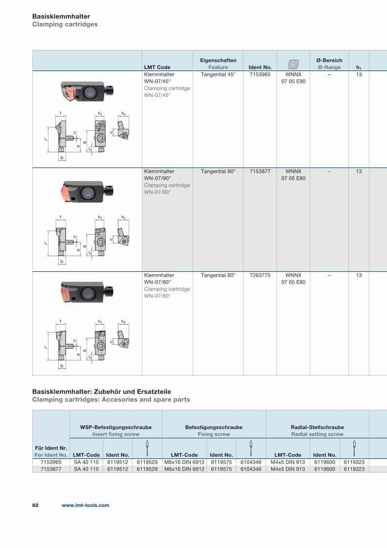
www.lmt-tools.com82
LMT CodeEigenschaften
Feature Ident No.Ø-Bereich Ø-Range h1
Klemmhalter
WN-07/45°
Clamping cartridge
WN-07/45°
Tangential 45° 7153965 WNNX
07 05 E90
– 13
Klemmhalter
WN-07/90°
Clamping cartridge
WN-07/90°
Tangential 90° 7153877 WNNX
07 05 E90
– 13
Klemmhalter
WN-07/80°
Clamping cartridge
WN-07/80°
Tangential 80° 7263775 WNNX
07 05 E80
– 13
BasisklemmhalterClamping cartridges
Basisklemmhalter: Zubehör und ErsatzteileClamping cartridges: Accesories and spare parts
Für Ident Nr. For Ident No.
WSP-Befestigungsschraube Insert fixing screw
Befestigungsschraube Fixing screw
Radial-Stellschraube Radial setting screw
LMT-Code Ident No. LMT-Code Ident No. LMT-Code Ident No.7153965 SA 40 115 6119512 6119529 M6x16 DIN 6912 6119575 6104346 M4x5 DIN 913 6119600 6119323
7153877 SA 40 115 6119512 6119529 M6x16 DIN 6912 6119575 6104346 M4x5 DIN 913 6119600 6119323
c
ew
u
l1
h2h1f
b
l3
uc
e
l1
h2h1f
b
l3
w
uc
e
l1
h2h1f
b
l3
w
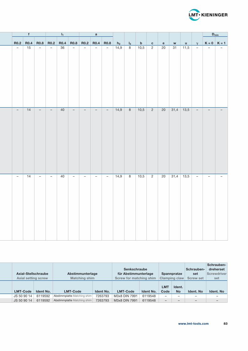
www.lmt-tools.com 83
f l1 a
h2 l3 b c e w u 𝛄
Dmin
R0.2 R0.4 R0.8 R0.2 R0.4 R0.8 R0.2 R0.4 R0.8 K = 0 K = 1– 15 – – 36 – – – – 14,9 8 10,5 2 20 31 11,5 – – –
– 14 – – 40 – – – – 14,9 8 10,5 2 20 31,4 13,5 – – –
– 14 – – 40 – – – – 14,9 8 10,5 2 20 31,4 13,5 – – –
Axial-Stellschraube Axial setting screw
Abstimmunterlage Matching shim
Senkschraube für Abstimmunterlage
Screw for matching shimSpannpratze
Clamping claw
Schrauben-set
Screw set
Schrauben-dreherset
Screwdriver set
LMT-Code Ident No. LMT-Code Ident No. LMT-Code Ident No.LMT Code
Ident. No Ident. No Ident. No
JS 50 90 14 6119592 Abstimmplatte Matching shim 7263793 M3x8 DIN 7991 6119548 – – – –
JS 50 90 14 6119592 Abstimmplatte Matching shim 7263793 M3x8 DIN 7991 6119548 – – – –
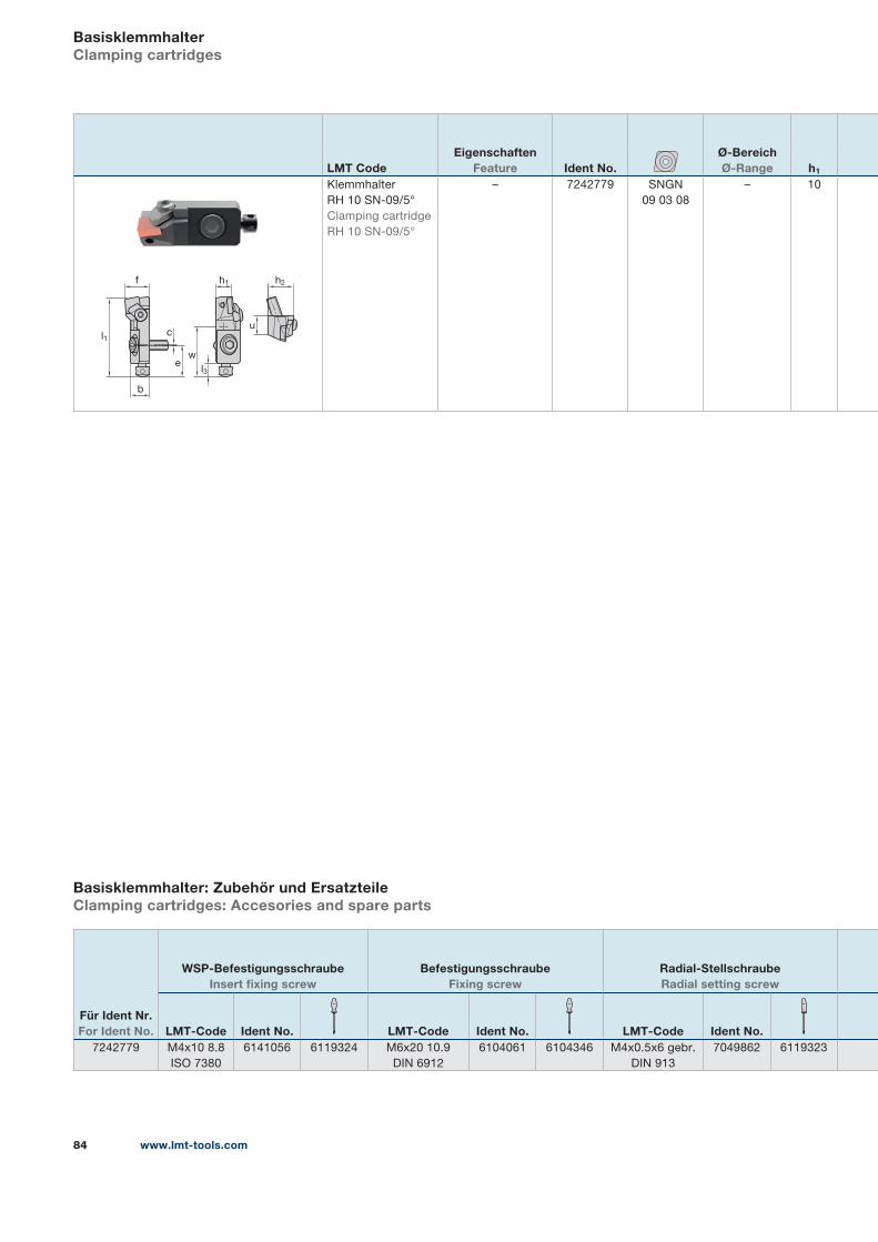
www.lmt-tools.com84
LMT CodeEigenschaften
Feature Ident No.Ø-Bereich Ø-Range h1
Klemmhalter
RH 10 SN-09/5°
Clamping cartridge
RH 10 SN-09/5°
– 7242779 SNGN
09 03 08
– 10
BasisklemmhalterClamping cartridges
Basisklemmhalter: Zubehör und ErsatzteileClamping cartridges: Accesories and spare parts
Für Ident Nr. For Ident No.
WSP-Befestigungsschraube Insert fixing screw
Befestigungsschraube Fixing screw
Radial-Stellschraube Radial setting screw
LMT-Code Ident No. LMT-Code Ident No. LMT-Code Ident No.7242779 M4x10 8.8
ISO 7380
6141056 6119324 M6x20 10.9
DIN 6912
6104061 6104346 M4x0.5x6 gebr.
DIN 913
7049862 6119323
uc
e
l1
h2h1f
b
l3
w
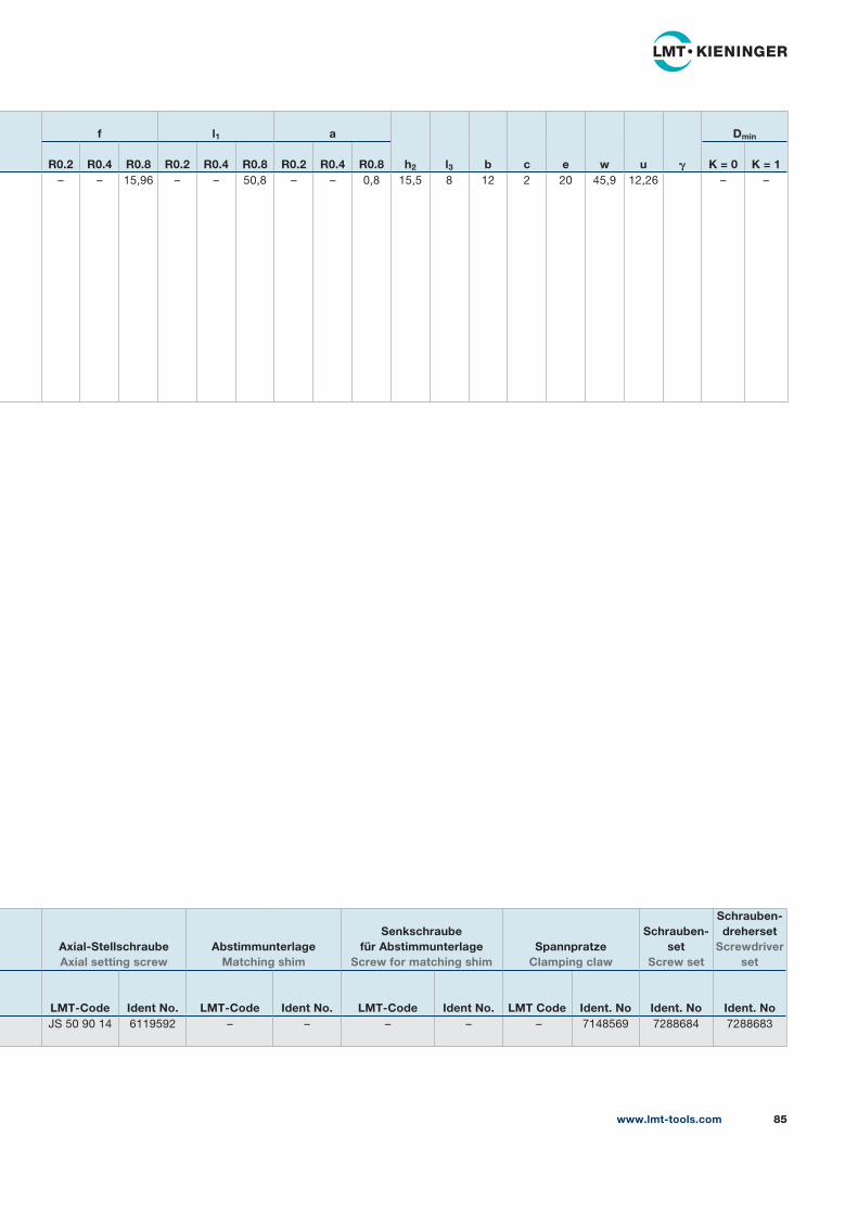
www.lmt-tools.com 85
f l1 a
h2 l3 b c e w u 𝛄
Dmin
R0.2 R0.4 R0.8 R0.2 R0.4 R0.8 R0.2 R0.4 R0.8 K = 0 K = 1– – 15,96 – – 50,8 – – 0,8 15,5 8 12 2 20 45,9 12,26 – –
Axial-Stellschraube Axial setting screw
Abstimmunterlage Matching shim
Senkschraube für Abstimmunterlage
Screw for matching shimSpannpratze
Clamping claw
Schrauben-set
Screw set
Schrauben-dreherset
Screwdriver set
LMT-Code Ident No. LMT-Code Ident No. LMT-Code Ident No. LMT Code Ident. No Ident. No Ident. NoJS 50 90 14 6119592 – – – – – 7148569 7288684 7288683
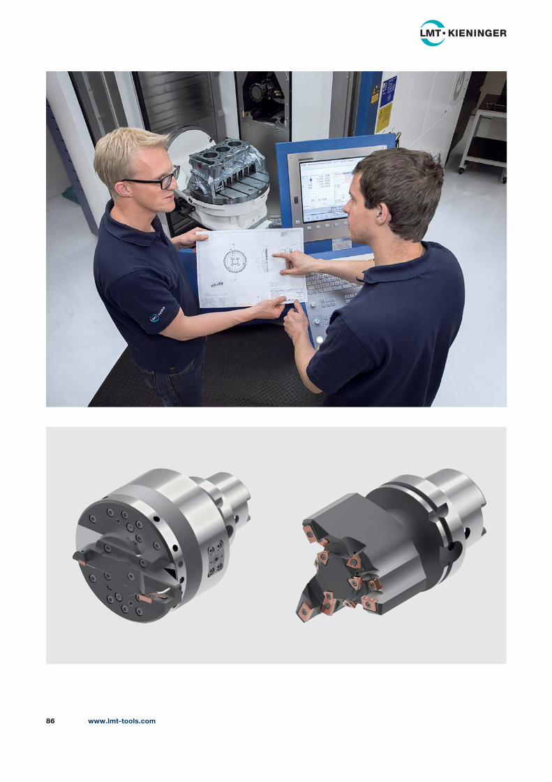
www.lmt-tools.com86
Unsere komplette Katalogreihe „Werkzeuge und Wissen“Our complete catalog serie “Tools and Knowledge”
LMT Tools FräsenWerkzeuge und Wissen LMT Tools MillingTools and Knowledge
www.lmt-tools.com
LMT Tools Gewinden und Bohren
Werkzeuge und Wissen
LMT Tools Threading and Drilling
Tools and Knowledge
www.lmt-tools.com
LMT Tools Gewinden und BohrenWerkzeuge und WissenLMT Tools Threading and DrillingTools and Knowledge
www.lmt-tools.com
LMT Tools ReibenWerkzeuge und Wissen LMT Tools ReamingTools and Knowledge
LMT Tools ReibenWerkzeuge und WissenLMT Tools ReamingTools and Knowledge
LMT Tools Fräsen Werkzeuge und WissenLMT Tools MillingTools and Knowledge
www.lmt-tools.com
LMT Fette Rollsysteme Werkzeuge und WissenLMT Fette Rolling SystemsTools and Knowledge
LMT Fette RollsystemeWerkzeuge und WissenLMT Fette Rolling SystemsTools and Knowledge
LMT Fette VerzahnenWerkzeuge und Wissen LMT Fette Gear CuttingTools and Knowledge
www.lmt-tools.com
Knowledge
LMT Fette VerzahnenWerkzeuge und WissenLMT Fette Gear CuttingTools and Knowledge
Pri
nte
d i
n G
erm
an
y,
No
. 7
313
714
(0
219
1 D
M/W
)
Brasilien / BrazilLMT Tools Brasil
Av. Cambacica 1200
Módulo 11
13097-160 São Paulo
Telefon +55 19 982439910
Telefax +55 11 55460476
ChinaLMT China Co. Ltd.
No. 9 Lanzhi Road
Jiangning Development Zone
211100 Nanjing
Telefon +86 25 52128866
Telefax +86 25 52106376
Deutschland / GermanyLMT Tool Systems
GmbH & Co. KG
Heidenheimer Strasse 84
73447 Oberkochen
Telefon +49 7364 9579-0
Telefax +49 7364 9579-8000
Frankreich / FranceLMT Belin France S.A.S.
Lieu dit „Les Cizes“
01590 Lavancia
Telefon +33 474 758989
Telefax +33 474 758990
Großbritannien und Irland /United Kingdom and IrelandLMT UK Ltd.
Unit 4202 Waterside Centre
Solihull Parkway
Birmingham Business Park
B377YN Birmingham
Telefon +44 121 7175830
Telefax +44 121 7175838
Indien / IndiaLMT (India) Private Limited
Plot No. A-40/1
Phase I, MIDC
Chakan Industrial Area Village:
Nighoje, Tal: Khed
410501 Pune
Telefon +91 2135614900
Telefax +91 42337704
KoreaLMT Korea Co. Ltd.
Room 1212
Anyang Trade Center
161 Simin-daero, Dongan-Gu
Anyang-Si
431-817 Gyeonggi-Do
South Korea
Telefon +82 31 3848600
Telefax +82 31 3842121
Mexiko / Mexico LMT Tools Mexico, SA de CV
Adolfo Prieto No. 1638
Colonia Del Valle Sur
03100 Mexico, DF
Telefon +52 55 40000653
Telefax +52 44 22215555
Österreich / AustriaLMT Tool Systems
GmbH & Co. KG
Mosetiggasse 1
1230 Wien
Telefon +43 680 3106101
Rumänien / Romania LMT Tool Systems RO SRL
Business Center Sibiu
Camera 301, Etaj 3
Str. Sibiului nr. 2
557260 Selimbar, Sibiu
Telefon +40 269 246092
Telefax +40 269 560614
Russland / Russia LLC LMT Tools
Serebryanicheskaya nab., 27
109028 Moscow
Telefon/Telefax +7 495 2807352
Spanien / Spain LMT Tool Systems GmbH
Sucursal en España
C/Agricultura local no.12
planta 1 no. 16–18
08320 El Masnou
Telefon +34 937127435
Telefon/Telefax +34 935407002
Tschechische Republikund Slowakei / Czech Republic and SlovakiaLMT Czech Republic s.r.o.
Dusikova 3
63800 Brno-Lesná
Telefon +420 548 218722
Telefax +420 548 218723
USAKanada / CanadaLMT USA Inc.
1081 S. Northpoint Blvd.
Waukegan, IL 60085
Telefon +1 847 3621560
Telefax +1 847 4731934
LMT Tools Niederlassungen und Servicestandorte LMT Tools subsidiaries and service organisations
LMT Belin France S.A.S.Lieu dit „Les Cizes“
01590 Lavancia
Frankreich
Telefon +33 474 758989
Telefax +33 474 758990
www.lmt-belin.com
LMT Fette Werkzeugtechnik GmbH & Co. KGGrabauer Strasse 24
21493 Schwarzenbek
Deutschland
Telefon +49 4151 12 - 0
Telefax +49 4151 3797
www.lmt-fette.com
LMT Kieninger GmbH & Co. KGVogesenstrasse 23
77933 Lahr
Deutschland
Telefon +49 7821 943 - 0
Telefax +49 7821 943 213
www.lmt-kieninger.com
LMT Onsrud LP1081 S. Northpoint Blvd.
Waukegan, IL 60085
USA
Telefon +1 847 3621560
Telefax +1 847 4731934
www.onsrud.com
1