Embed Size (px)
Citation preview
Umwelt-Geräte-Technik GmbH • Email: [email protected] • Web: www.ugt-online.de
Müncheberg • Freising • Homécourt
Manual Issue: 25/04/12
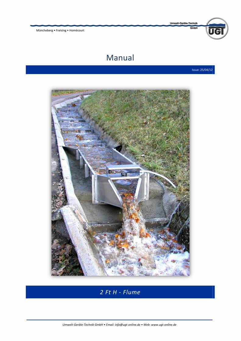
2 Ft H - Flume
Umwelt-Geräte-Technik GmbH • Email: [email protected] • Web: www.ugt-online.de Page 2 of 10
Müncheberg • Freising • Homécourt
Content
1. Introduction ................................................................................................................. 3
2. System components ..................................................................................................... 3
3. Installation - instruction ............................................................................................... 4
4. Flow Rate Measurement .............................................................................................. 4
4.1. Measuring Principle ........................................................................................................ 4
4.2. Flow rate table for UGT - 2 Ft - H - Flume ...................................................................... 5
5. Data – Recording System .............................................................................................. 7
5.1. Start recording ............................................................................................................... 7
5.2. Software Quick Installation Guide .................................................................................. 7
5.3. Connecting to the data logger ........................................................................................ 8
5.4. Sensor Calibration ........................................................................................................ 10
Umwelt-Geräte-Technik GmbH • Email: [email protected] • Web: www.ugt-online.de Page 3 of 10
Müncheberg • Freising • Homécourt
1. Introduction
H-Flumes are used for the determination of the flow rate in open channels. The flow rate is the periodical measured amount of water flowing through a chanel in a defined time interval. Generally it is specified in liters/second (l/s) or cubic meters/hour (m³/h).
H-Flumes provide an excellent accuracy for a wide ride range of flow rates. Hence they are especially qualified for channels with strongly varying discharge volumes, for the determination of storm event or seasonal runoffs and snow melt runoff. But also agricultural and industrial runoffs are determined using H-Flumes.
The use of an H-Flume requires an open channel with a free drainage at the H-Flume outlet as well as an approach channel with same height and width put in front of the H-Flume. The length of the approach channel shall enable an even dispersal of the flow over the complete width.
A big advantage of the H-Flumes compared to other flow rate measuring systems is their low susceptibility to dirt in the water. Even foliage and floating refuse don`t influence the measurement, as long as they are small enough to not block the outlet.
2. System components
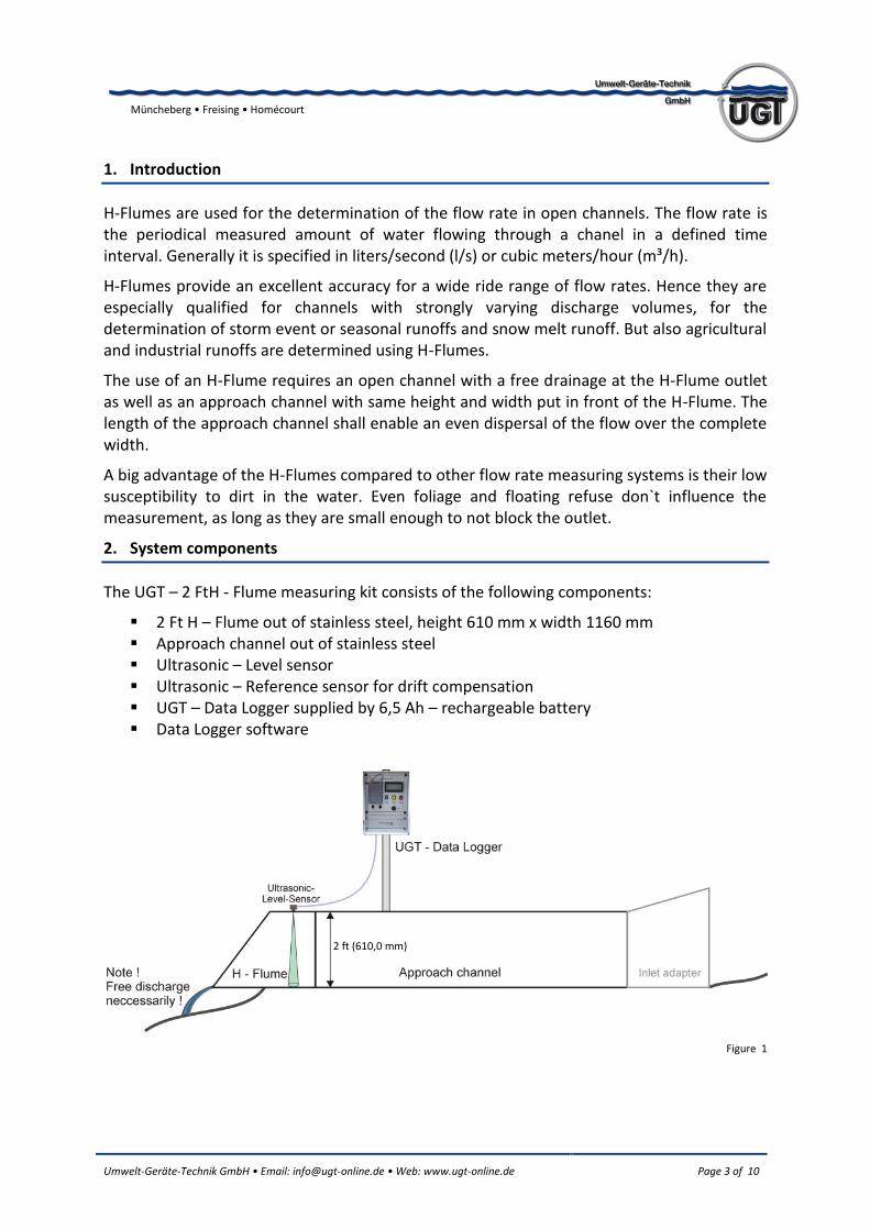
The UGT – 2 FtH - Flume measuring kit consists of the following components:
2 Ft H – Flume out of stainless steel, height 610 mm x width 1160 mm Approach channel out of stainless steel Ultrasonic – Level sensor Ultrasonic – Reference sensor for drift compensation UGT – Data Logger supplied by 6,5 Ah – rechargeable battery Data Logger software
Figure 1
2 ft (610,0 mm)
Umwelt-Geräte-Technik GmbH • Email: [email protected] • Web: www.ugt-online.de Page 4 of 10
Müncheberg • Freising • Homécourt
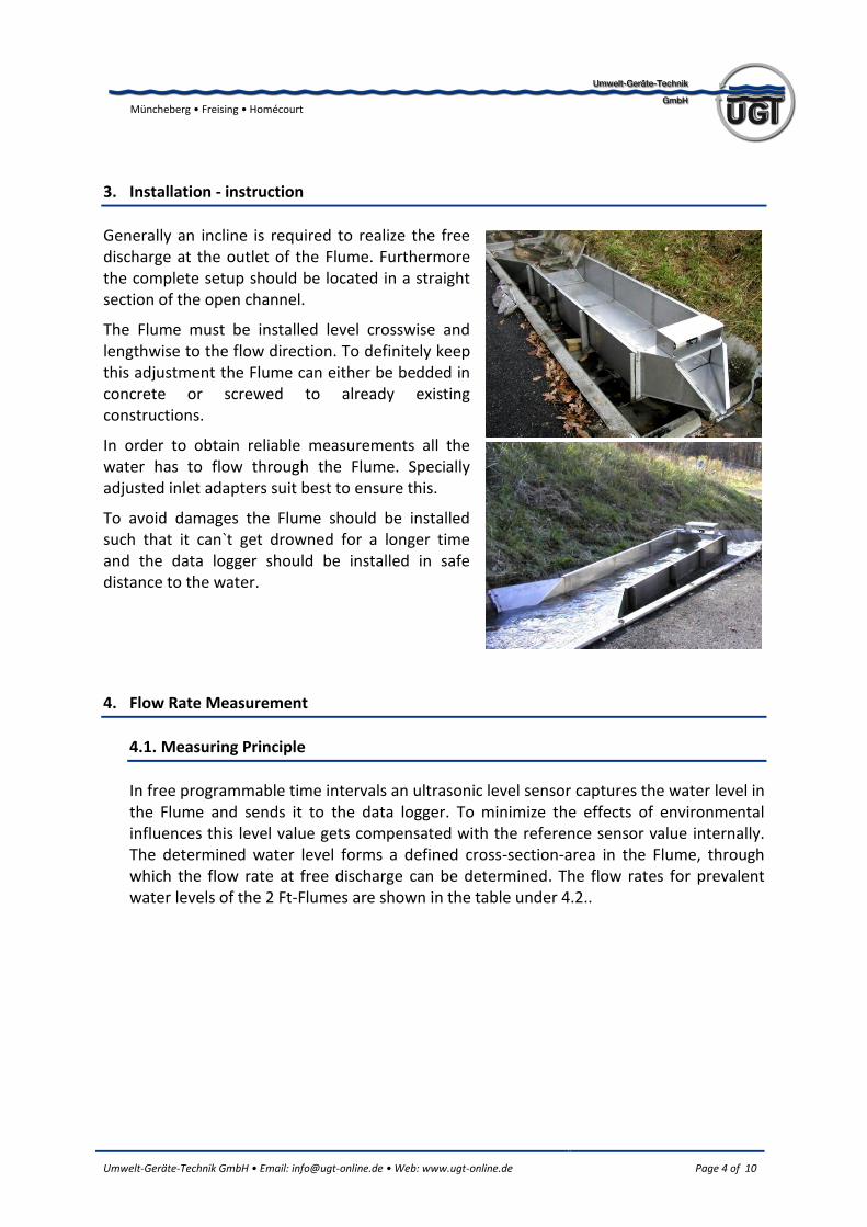
3. Installation - instruction
Generally an incline is required to realize the free discharge at the outlet of the Flume. Furthermore the complete setup should be located in a straight section of the open channel.
The Flume must be installed level crosswise and lengthwise to the flow direction. To definitely keep this adjustment the Flume can either be bedded in concrete or screwed to already existing constructions.
In order to obtain reliable measurements all the water has to flow through the Flume. Specially adjusted inlet adapters suit best to ensure this.
To avoid damages the Flume should be installed such that it can`t get drowned for a longer time and the data logger should be installed in safe distance to the water.
4. Flow Rate Measurement
4.1. Measuring Principle
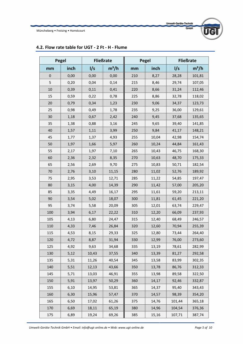
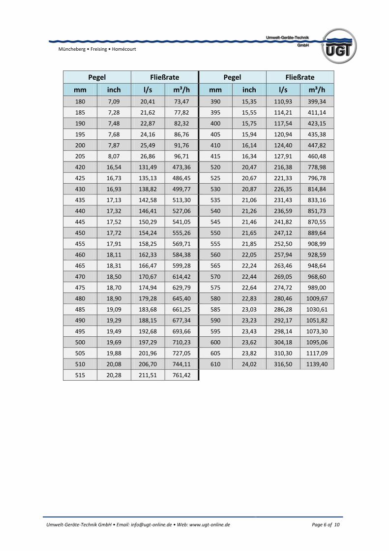
In free programmable time intervals an ultrasonic level sensor captures the water level in the Flume and sends it to the data logger. To minimize the effects of environmental influences this level value gets compensated with the reference sensor value internally. The determined water level forms a defined cross-section-area in the Flume, through which the flow rate at free discharge can be determined. The flow rates for prevalent water levels of the 2 Ft-Flumes are shown in the table under 4.2..
Umwelt-Geräte-Technik GmbH • Email: [email protected] • Web: www.ugt-online.de Page 5 of 10
Müncheberg • Freising • Homécourt
4.2. Flow rate table for UGT - 2 Ft - H - Flume
Pegel Fließrate Pegel Fließrate
mm inch l/s m³/h mm inch l/s m³/h
0 0,00 0,00 0,00 210 8,27 28,28 101,81
5 0,20 0,04 0,14 215 8,46 29,74 107,05
10 0,39 0,11 0,41 220 8,66 31,24 112,46
15 0,59 0,22 0,78 225 8,86 32,78 118,02
20 0,79 0,34 1,23 230 9,06 34,37 123,73
25 0,98 0,49 1,78 235 9,25 36,00 129,61
30 1,18 0,67 2,42 240 9,45 37,68 135,65
35 1,38 0,88 3,16 245 9,65 39,40 141,85
40 1,57 1,11 3,99 250 9,84 41,17 148,21
45 1,77 1,37 4,93 255 10,04 42,98 154,74
50 1,97 1,66 5,97 260 10,24 44,84 161,43
55 2,17 1,97 7,10 265 10,43 46,75 168,30
60 2,36 2,32 8,35 270 10,63 48,70 175,33
65 2,56 2,69 9,70 275 10,83 50,71 182,54
70 2,76 3,10 11,15 280 11,02 52,76 189,92
75 2,95 3,53 12,71 285 11,22 54,85 197,47
80 3,15 4,00 14,39 290 11,42 57,00 205,20
85 3,35 4,49 16,17 295 11,61 59,20 213,11
90 3,54 5,02 18,07 300 11,81 61,45 221,20
95 3,74 5,58 20,09 305 12,01 63,74 229,47
100 3,94 6,17 22,22 310 12,20 66,09 237,93
105 4,13 6,80 24,47 315 12,40 68,49 246,57
110 4,33 7,46 26,84 320 12,60 70,94 255,39
115 4,53 8,15 29,33 325 12,80 73,44 264,40
120 4,72 8,87 31,94 330 12,99 76,00 273,60
125 4,92 9,63 34,68 335 13,19 78,61 282,99
130 5,12 10,43 37,55 340 13,39 81,27 292,58
135 5,31 11,26 40,54 345 13,58 83,99 302,35
140 5,51 12,13 43,66 350 13,78 86,76 312,33
145 5,71 13,03 46,91 355 13,98 89,58 322,50
150 5,91 13,97 50,29 360 14,17 92,46 332,87
155 6,10 14,95 53,81 365 14,37 95,40 343,43
160 6,30 15,96 57,47 370 14,57 98,39 354,20
165 6,50 17,02 61,26 375 14,76 101,44 365,18
170 6,69 18,11 65,19 380 14,96 104,54 376,36
175 6,89 19,24 69,26 385 15,16 107,71 387,74
Umwelt-Geräte-Technik GmbH • Email: [email protected] • Web: www.ugt-online.de Page 6 of 10
Müncheberg • Freising • Homécourt
Pegel Fließrate Pegel Fließrate
mm inch l/s m³/h mm inch l/s m³/h
180 7,09 20,41 73,47 390 15,35 110,93 399,34
185 7,28 21,62 77,82 395 15,55 114,21 411,14
190 7,48 22,87 82,32 400 15,75 117,54 423,15
195 7,68 24,16 86,76 405 15,94 120,94 435,38
200 7,87 25,49 91,76 410 16,14 124,40 447,82
205 8,07 26,86 96,71 415 16,34 127,91 460,48
420 16,54 131,49 473,36 520 20,47 216,38 778,98
425 16,73 135,13 486,45 525 20,67 221,33 796,78
430 16,93 138,82 499,77 530 20,87 226,35 814,84
435 17,13 142,58 513,30 535 21,06 231,43 833,16
440 17,32 146,41 527,06 540 21,26 236,59 851,73
445 17,52 150,29 541,05 545 21,46 241,82 870,55
450 17,72 154,24 555,26 550 21,65 247,12 889,64
455 17,91 158,25 569,71 555 21,85 252,50 908,99
460 18,11 162,33 584,38 560 22,05 257,94 928,59
465 18,31 166,47 599,28 565 22,24 263,46 948,64
470 18,50 170,67 614,42 570 22,44 269,05 968,60
475 18,70 174,94 629,79 575 22,64 274,72 989,00
480 18,90 179,28 645,40 580 22,83 280,46 1009,67
485 19,09 183,68 661,25 585 23,03 286,28 1030,61
490 19,29 188,15 677,34 590 23,23 292,17 1051,82
495 19,49 192,68 693,66 595 23,43 298,14 1073,30
500 19,69 197,29 710,23 600 23,62 304,18 1095,06
505 19,88 201,96 727,05 605 23,82 310,30 1117,09
510 20,08 206,70 744,11 610 24,02 316,50 1139,40
515 20,28 211,51 761,42
Umwelt-Geräte-Technik GmbH • Email: [email protected] • Web: www.ugt-online.de Page 7 of 10
Müncheberg • Freising • Homécourt
5. Data – Recording System
The UGT – Flow Rate Measurement Kit includes a specially configured UGT – Data Logger.
The data logger recalls the level value as well as the reference value in defined periods and determines the present flow rate. All three values are stored on the data logger. By the provided configuration and data acquisition software UGTLog 2.7 the user can read out the collected data via the serial interface.
UGTLog 2.7 works with Windows®95 and higher. If the system is optionally equipped with a modem, all software functions are available via the telephone network. The complete description of the UGTLog software is to find in the appendix.
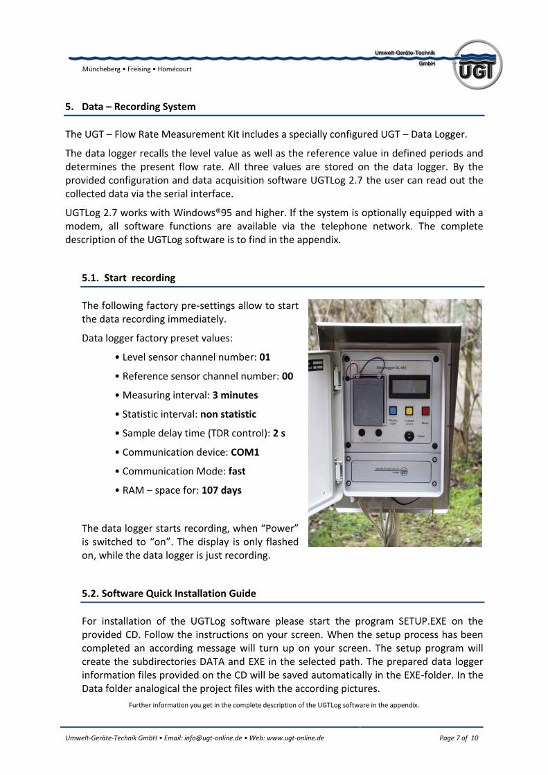
5.1. Start recording
The following factory pre-settings allow to start the data recording immediately.
Data logger factory preset values:
• Level sensor channel number: 01
• Reference sensor channel number: 00
• Measuring interval: 3 minutes
• Statistic interval: non statistic
• Sample delay time (TDR control): 2 s
• Communication device: COM1
• Communication Mode: fast
• RAM – space for: 107 days
The data logger starts recording, when “Power” is switched to “on”. The display is only flashed on, while the data logger is just recording.
5.2. Software Quick Installation Guide
For installation of the UGTLog software please start the program SETUP.EXE on the provided CD. Follow the instructions on your screen. When the setup process has been completed an according message will turn up on your screen. The setup program will create the subdirectories DATA and EXE in the selected path. The prepared data logger information files provided on the CD will be saved automatically in the EXE-folder. In the Data folder analogical the project files with the according pictures.
Further information you get in the complete description of the UGTLog software in the appendix.
Umwelt-Geräte-Technik GmbH • Email: [email protected] • Web: www.ugt-online.de Page 8 of 10
Müncheberg • Freising • Homécourt
5.3. Connecting to the data logger
At first you have to establish the hardware connection from the serial interface (RS232) of your computer (laptop, notebook, pc workstation etc.) to the data logger using the provided UGT - data cable. Then start the UGTLog program by double click on the UGT
icon on your desktop.
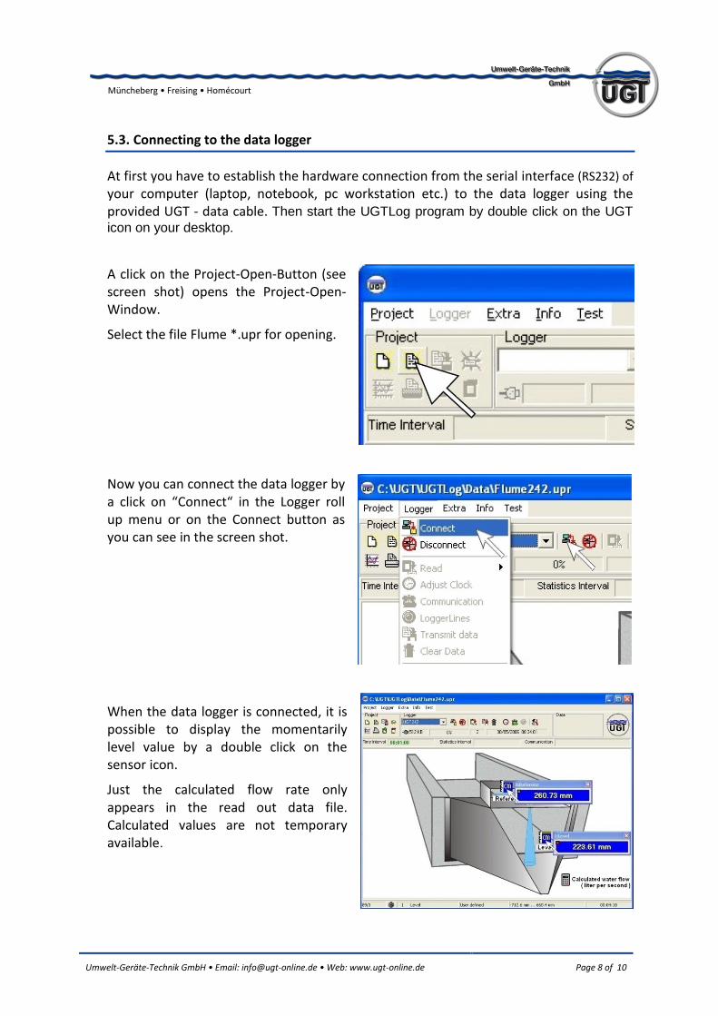
A click on the Project-Open-Button (see screen shot) opens the Project-Open-Window.
Select the file Flume *.upr for opening.
Now you can connect the data logger by a click on “Connect“ in the Logger roll up menu or on the Connect button as you can see in the screen shot.
When the data logger is connected, it is possible to display the momentarily level value by a double click on the sensor icon.
Just the calculated flow rate only appears in the read out data file. Calculated values are not temporary available.
Umwelt-Geräte-Technik GmbH • Email: [email protected] • Web: www.ugt-online.de Page 9 of 10
Müncheberg • Freising • Homécourt
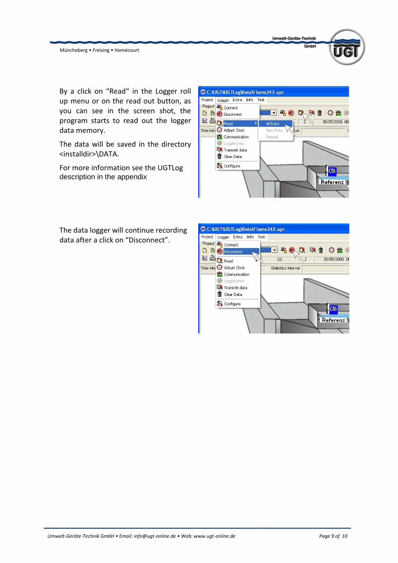
By a click on “Read“ in the Logger roll up menu or on the read out button, as you can see in the screen shot, the program starts to read out the logger data memory.
The data will be saved in the directory <installdir>\DATA.
For more information see the UGTLog description in the appendix
The data logger will continue recording data after a click on “Disconnect”.
Umwelt-Geräte-Technik GmbH • Email: [email protected] • Web: www.ugt-online.de Page 10 of 10
Müncheberg • Freising • Homécourt
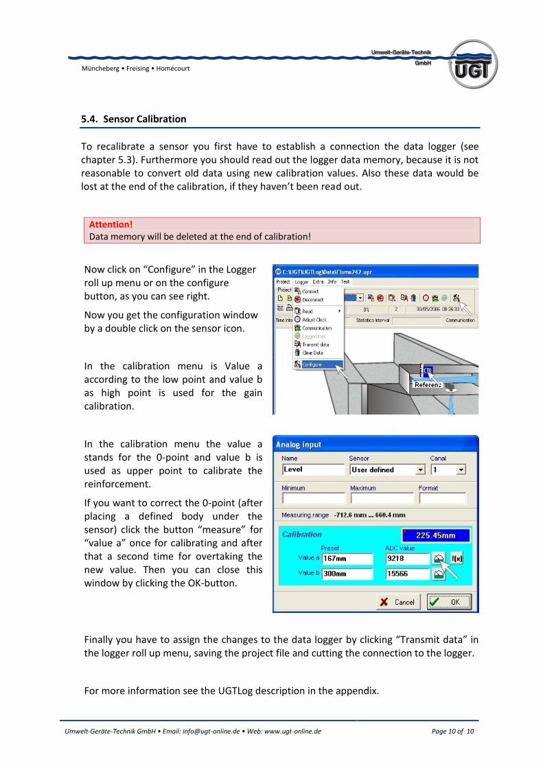
5.4. Sensor Calibration
To recalibrate a sensor you first have to establish a connection the data logger (see chapter 5.3). Furthermore you should read out the logger data memory, because it is not reasonable to convert old data using new calibration values. Also these data would be lost at the end of the calibration, if they haven’t been read out.
Attention! Data memory will be deleted at the end of calibration!
Now click on “Configure” in the Logger roll up menu or on the configure button, as you can see right.
Now you get the configuration window by a double click on the sensor icon.
In the calibration menu is Value a according to the low point and value b as high point is used for the gain calibration.
In the calibration menu the value a stands for the 0-point and value b is used as upper point to calibrate the reinforcement.
If you want to correct the 0-point (after placing a defined body under the sensor) click the button “measure” for “value a” once for calibrating and after that a second time for overtaking the new value. Then you can close this window by clicking the OK-button.
Finally you have to assign the changes to the data logger by clicking “Transmit data” in the logger roll up menu, saving the project file and cutting the connection to the logger.
For more information see the UGTLog description in the appendix.