Embed Size (px)
Citation preview
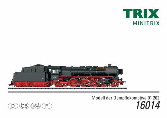
Modell der Dampfl okomotive 01 202
16014D GB USA F

2

3
Inhaltsverzeichnis SeiteInformationen zum Vorbild 4Sicherheitshinweise 6 Wichtige Hinweise 6Funktionen 6Hinweise zum Digitalbetrieb 6Schaltbare Funktionen 7Configurations Variablen (CVs) 8Wartung und Instandhaltung 18Ersatzteile 21
Table of Contents Page Information about the prototype 5Safety Notes 10Important Notes 10Functions 10Notes on digital operation 10Controllable Functions 11Configuration Variables (CVs) 12Service and maintenance 18Spare Parts 21
Sommaire PageInformations concernant la locomotive réelle 5Remarques importantes sur la sécurité 14Information importante 14Fonctionnement 14Remarques relatives au fonctionement en mode digital 14Fonctions commutables 15Variables de configuration (CVs) 16Entretien et maintien 18Pièces de rechange 21

4
Informationen zum Vorbild Schnellzuglokomotiven waren durch ihre Kraft, Eleganz und Geschwindigkeit schon immer die Stars unter den Dampflokomotiven. So ist die schwere Schnellzugloko-motive der Baureihe 01 wohl der Inbegriff der deutschen Einheitslokomotive schlechthin. Sie lief genauso zuverlässig vor repräsentativen Expresszügen wie vor gewöhnlichen Personenzügen.Bis 1938 entstanden bei verschiedenen deutschen Herstel-lern insgesamt 231 Maschinen der Baureihe 01. Dazu kamen noch 10 Lokomotiven der Baureihe 02, die zwischen 1937 und 1942 zur Baureihe 01 umgebaut wurden. Nach dem 2. Weltkrieg verblieben 165 Lokomotiven der Baureihe 01 in den westlichen und 70 in der sowjetischen Besatzungszo-ne, wobei einige wegen schwerer Schäden ausgemustert werden mussten.Ab den 50er-Jahren bauten beide deutschen Bahnen die Lokomotive mehrfach um und passten sie den neuen Einsatzbedingungen sowie dem technischen Fortschritt an. So wurden im Westen die großen Wagner- durch die kleinen Witte-Windleitbleche ersetzt, die Luft- und Speisepumpe wanderte bei den DB-Lokomotiven von der Rauchkammer-nische hin zur Kesselmitte und bei zahlreichen Lokomotiven verschwand die Frontschürze zwischen Pufferbohle und Umlauf.Der Einsatz der Baureihe 01 endete bei der DB Mitte der 70er-Jahre, bei der DR rollte sie Anfang der 80er aufs Abstellgleis.

5
Information about the prototypeExpress locomotives were always the stars among steam locomotives by virtue of their power, elegance, and speed. The class 01 heavy express locomotive was probably for all intents and purposes the personification of the German standard design locomotive. It was reliable motive power for impressive express trains as well as for mundane passenger trains.By 1938, a total of 231 class 01 locomotives had been produced by different German builders. In addition, there were also 10 class 02 locomotives rebuilt between 1937 and 1942 to the class 01. After World War II, 165 of the class 01 locomotives remained in the western occupation zone and 70 in the Soviet zone, of which several had to be retired due to extensive damage. Starting in the Fifties, both German railroads rebuilt their locomotives several times and adapted them to new uses by making use of technical progress. In West Germany, the large Wagner smoke deflectors were replaced by the small Witte versions, the compressor and feed water pump wandered on the DB locomotives from the niche on the smoke box to the center of the boiler, and the front skirting between the buffer beam and the running boards was removed on numerous units.The class 01 was taken out of service on the DB in the middle of the Seventies; on the DR they lasted until the Eighties.
Informations concernant le modèle réel La puissance, l’élégance et la vitesse des locomotives pour trains rapides en ont toujours fait des stars parmi les locomotives à vapeur. La locomotive lourde de la série 01 pour trains rapides est ainsi le symbole même de la locomotive unifiée allemande. Elle tractait tout aussi bien les trains express représentatifs que les trains voyageurs habituels.Jusqu’en 1938, 231 machines de la série 01 furent construites par différentes firmes allemandes. S’y ajou-tèrent encore 10 locomotives de la série 02 transformées en série 01 entre 1937 et 1942. Après la seconde guerre mondiale, 165 locomotives de la série 01 restèrent dans la zone ouest et 70 dans la zone d’occupation soviétique, quelques unes ayant été réformées en raison de dom-mages importants.A partir des années 50, les deux sociétés de chemins de fer allemandes transformèrent la locomotive à plusieurs reprises et l’adaptèrent aux nouvelles conditions de service ainsi qu’au progrès technique. A l’ouest, les grands écrans pare-fumée Wagner furent par exemple remplacés par les petits écrans Witte, la pompe à air et la pompe d’alimentation furent déplacées de la boîte à fumée vers le milieu de la chaudière et pour de nombreuses locomotives, le tablier frontal disparut entre la traverse porte-tampons et le tablier.A la DB, la série 01 fut mise hors service au milieu des années 70 ; à la DR, les machines étaient encore utilisées au début des années 80 sur des voies de remisage.

6
Sicherheitshinweise• DieLokdarfnurmiteinemdafürbestimmtenBetriebssys-
tem eingesetzt werden.• DieLokdarfnichtmitmehralseinerLeistungsquelle
versorgt werden.• BeachtenSieunbedingtdieSicherheitshinweiseinder
Bedienungsanleitung zu Ihrem Betriebssystem.• Analog14Volt=,digital22Volt~.• FürdenkonventionellenBetriebderLokmussdas
Anschlussgleis entstört werden. Dazu ist das Entstörset 14972 zu verwenden. Für Digitalbetrieb ist das Entstörset nicht geeignet.
• SetzenSiedasModellkeinerdirektenSonneneinstrah-lung, starken Temperaturschwankungen oder hoher Luftfeuchtigkeit aus.
• DasverwendeteGleisanschlusskabeldarfmaximal 2 Meter lang sein.
• ACHTUNG! Funktionsbedingte scharfe Kanten und Spitzen. • VerbauteLED`sentsprechenderLaserklasse1nach
Norm EN 60825-1.
Wichtige Hinweise• DieBedienungsanleitungunddieVerpackungsind
Bestandteile des Produktes und müssen deshalb aufbe-wahrt sowie bei Weitergabe des Produktes mitgegeben werden.
• FürReparaturenoderErsatzteilewendenSiesichbitteanIhren Trix-Fachhändler.
• GewährleistungundGarantiegemäßderbeiliegendenGarantieurkunde.
• Entsorgung:www.maerklin.com/en/imprint.htmlAllgemeiner Hinweis zur Vermeidung elektromagnetischer Störungen: Um den bestimmungsgemäßen Betrieb zu gewährleisten, ist ein permanenter, einwandfreier Rad-Schiene-Kontakt der Fahrzeuge erforderlich. Führen Sie keine Veränderungen an stromführenden Teilen durch.
Funktionen• EingebauteElektronikzumwahlweisenBetriebmit
konventionellem Gleichstrom-Fahrgerät (max. ±12 Volt), Trix Systems, Trix Selectrix (SX1) und Selectrix 2 (SX2) oder Digitalsystemen nach NMRA-Norm.
• AutomatischeSystemerkennungzwischenDigital-undAnalog-Betrieb.
• KeineautomatischeSystemerkennungzwischendenDigital-Systemen.
• Dreilicht-SpitzensignalmitderFahrtrichtungwechselnd.
Hinweise zum Digitalbetrieb • BeimerstenBetriebineinemDigital-System(SX1,SX2
oder DCC) muss der Decoder auf dieses Digital-System eingestellt werden. Dazu ist der Decoder einmal in diesem Digitalsystem zu programmieren (z.B. Adresse ändern).
7
Schaltbare Funktionen 2
7
1
6
STOP
PR
3
8
Sx
5
ON
Lz
4
9
1/2
Central- Control66800 f0 - f3 f4 - f7
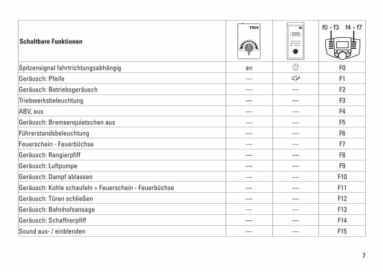
Spitzensignal fahrtrichtungsabhängig an F0
Geräusch:Pfeife — F1
Geräusch:Betriebsgeräusch — — F2
Triebwerksbeleuchtung — — F3
ABV, aus — — F4
Geräusch:Bremsenquietschenaus — — F5
Führerstandsbeleuchtung — — F6
Feuerschein - Feuerbüchse — — F7
Geräusch:Rangierpfiff — — F8
Geräusch:Luftpumpe — — F9
Geräusch:Dampfablassen — — F10
Geräusch:Kohleschaufeln+Feuerschein-Feuerbüchse — — F11
Geräusch:Türenschließen — — F12
Geräusch:Bahnhofsansage — — F13
Geräusch:Schaffnerpfiff — — F14
Soundaus-/einblenden — — F15

8
CV Bedeutung Wert DCC ab Werk
1 Adresse 1 – 127 3
2 Minimalgeschwindigkeit 0 – 15 10
3 Anfahrverzögerung 0 – 255 5
4 Bremsverzögerung 0 – 255 5
5 Maximalgeschwindigkeit 0 – 127 109
17 ErweiterteAdresse(obererTeil)(CV29,Bit5=1) 0 – 255 192
18 ErweiterteAdresse(untererTeil)(CV29,Bit5=1) 0 – 255 0
19 Traktionsadresse(0=inaktiv,Wert+128=inverseFahrtrichtung) 0 – 127 0
21 Traktions-Modus; Bit 0 – 7 =̂ F1 – F8 0 – 255 0
22 Traktions-Modus; Bit 0 – 1 =̂ FLf – FLr, Bit 2 – 5 =̂ F9 – F12 0 – 63 0
29
Bit0:UmpolungFahrtrichtungBit1:AnzahlFahrstufen14-28/126Bit2:DCCBetriebmitBremsstrecke DCC-, Selectrix- und Gleichstrombetrieb Bit5:Adressumfang7Bit/14Bit
0 – 255 6
52 Dimmung Licht 0 – 31 31
902 Lautstärke 0 – 255 255

9
par Bedeutung Wert SX2 ab Werk
001 Adresse Einer- u. Zehner-Stelle 0 – 99 1
002 Adresse Hunderter- u. Tausender-Stelle 0 – 99 10
011 Anfahrverzögerung 0 – 255 5
012 Bremsverzögerung 0 – 255 5
013 Maximalgeschwindigkeit 0 – 127 109
014 Mindestgeschwindigkeit 0 – 15 10
018 Geschwindigkeit Rangiergang 0 – 127 109
021 Bremsabschnitte; 1 oder 2 0, 1 0
081 Dimmung Licht normal 0 – 31 31
082 Dimmung Licht alternativ 0 – 31 15
WerkseinstellungfürSX1:01-742,erweitert:00-274

10
• Disposing:www.maerklin.com/en/imprint.htmlGeneral Note to Avoid Electromagnetic Interference: A permanent, flawless wheel-rail contact is required in order to guarantee operation for which a model is designed. Do not make any changes to current-conducting parts.
Functions • Built-inelectroniccircuitforoptionaloperationwith
a conventional DC train controller (max. ±12 volts), Trix Systems, Trix Selectrix (SX1), and Selectrix 2 (SX2), or digital systems adhering to the NMRA standards.
• Automaticsystemrecognitionbetweendigitalandanalogoperation.
• Noautomaticsystemrecognitionbetweenthedigitalsystems.
• Tripleheadlightsthatchangeoverwiththedirectionoftravel.
Notes on digital operation • Whenoperatinginadigitalsystemforthefirsttime(SX1,
SX2, or DCC), the decoder must be set to this digital sys-tem. To do this, the decoder must be programmed once in thisdigitalsystem(example:changetheaddress).
Safety Notes• Thislocomotiveisonlytobeusedwiththeoperating
system it is designed for.• Thislocomotivemustnotbesuppliedwithpowerfrom
more than one power pack.• Paycloseattentiontothesafetynotesintheinstructions
for your operating system.• Analog14voltsDC,digital22voltsAC.• Thefeedertrackmustbeequippedtopreventinter-
ference with radio and television reception, when the locomotive is to be run in conventional operation. The 14972 interference suppression set is to be used for this purpose. The interference suppression set is not suitable for digital operation.
• Donotexposethemodeltodirectsunlight,extremechanges in temperature, or high humidity.
• Thewireusedforfeederconnectionstothetrackmaybeamaximumof2meters/78incheslong.
• WARNING! Sharp edges and points required for operation. • TheLEDsinthisitemcorrespondtoLaserClass1accor-
ding to Standard EN 60825-1.
Important Notes• Theoperatinginstructionsandthepackagingareacom-
ponent part of the product and must therefore be kept as well as transferred along with the product to others.
• PleaseseeyourauthorizedTrixdealerforrepairsorspare parts.
• Thewarrantycardincludedwiththisproductspecifiesthe warranty conditions.

11
Controllable Functions 2
7
1
6
STOP
PR
3
8
Sx
5
ON
Lz
4
9
1/2
Central- Control66800 f0 - f3 f4 - f7
Headlights on F0
Soundeffect:Whistleblast — F1
Soundeffect:Operatingsounds — — F2
Running gear lights — — F3
ABV, off — — F4
Soundeffect:Squealingbrakesoff — — F5
Engineer‘s cab lighting — — F6
Glow from firebox — — F7
Soundeffect:Switchingwhistle — — F8
Soundeffect:Airpump — — F9
Soundeffect:Blowingoffsteam — — F10
Soundeffect:Coalbeingshoveled+Glowfromfirebox — — F11
Soundeffect:Doorsbeingclosed — — F12
Soundeffect:Stationannouncements — — F13
Soundeffect:Conductorwhistle — — F14
Soundfadeoff/on — — F15

12
CV Discription DCC Value Factory Setting
1 Address 1 – 127 3
2 Minimum Speed 0 – 15 10
3 Acceleration delay 0 – 255 5
4 Braking delay 0 – 255 5
5 Maximum speed 0 – 127 109
17 Extendetaddress(upperpart)(CV29,Bit5=1) 0 – 255 192
18 Extendetaddress(lowerpart)(CV29,Bit5=1) 0 – 255 0
19 Consistaddress(0=inactive,Value+128=inversedirection) 0 – 127 0
21 Motive Power Mode; Bit 0 – 7 =̂ F1 – F8 0 – 255 0
22 Motive Power Mode; Bit 0 – 1 =̂ FLf – FLr, Bit 2 – 5 =̂ F9 – F12 0 – 63 0
29
Bit0:TraveldirectionpolarityreversalBit1:numberofspeedlevels14–28/126Bit2:DCCOperationwithbrakingBlock DCC-, Selectrix and DC power operation Bit5:addresssize7Bit/14Bit
0 – 255 6
52 Dimming of lights 0 – 31 31
902 Volume 0 – 255 255

13
par Discription SX2 Value Factory Setting
001 Address for one and ten placeholder 0 – 99 1
002 Address for hundred and thousand placeholder 0 – 99 10
011 Acceleration delay 0 – 255 5
012 Braking delay 0 – 255 5
013 Maximum speed 0 – 127 109
014 Minimum speed 0 – 15 10
018 Speed for switching range 0 – 127 109
021 Braking section; 1 or 2 0, 1 0
081 Dimming of lights, normal 0 – 31 31
082 Dimming of lights, alternative 0 – 31 15
FactorysettingforSX1:01-742,advanced:00-274

14
Remarques importantes sur la sécurité• Lalocomotivenepeutêtreutiliséequ‘aveclesystème
d‘exploitation indiqué.• Lalocomotivenepeutêtrealimentéeencourantquepar
une seule source de courant.• Veuillezimpérativementrespecterlesremarquessur
la sécurité décrites dans le mode d’emploi en ce qui concerne le système d’exploitation.
• Analogique14V=,numérique22Volt~.• Pourl’exploitationdelalocomotiveenmodeconventi-
onnel, la voie de raccordement doit être déparasitée. A cet effet, utiliser le set de déparasitage réf. 14972. Le set de déparasitage ne convient pas pour l’exploitation en mode numérique.
• Nepasexposerlemodèleàunensoleillementdirect,à de fortes variations de température ou à un taux d‘humidité important.
• Lecâblederaccordementàlavoieutilisénedoitenaucun cas dépasser deux mètres.
• ATTENTION! Pointes et bords coupants lors du fonction-nement du produit.
• LesDELinstalléescorrespondentàlaclasselaser1selon la norme EN 60825-1.
Information importante• Lanoticed‘utilisationetl’emballagefontpartieintégrante
du produit ; ils doivent donc être conservés et, le cas échéant, transmis avec le produit.
• Pourtouteréparationouremplacementdepièces,adressez vous à votre détaillant-spécialiste Trix.
• Garantielégaleetgarantiecontractuelleconformémentau certificat de garantie ci-joint.
• Elimination:www.maerklin.com/en/imprint.htmlIndication d‘ordre général pour éviter les interférences électromagnétiques: La garantie de l‘exploitation normale nécessite un contact roue-rail permanent et irréprochable. Ne procédez à aucune modification sur des éléments conducteurs de courant.
Fonctionnement• Module électronique intégré pour exploitation au choix avec
régulateur de marche conventionnel c.c. (max. ±12 volts), Trix Systems, Trix Selectrix (SX1) et Selectrix 2 (SX2) ou systèmes numériques conformes à la norme NMRA.
• Reconnaissanceautomatiquedusystèmeentreexploita-tions numérique et analogique.
• Pasdereconnaissanceautomatiquedusystèmeentreles systèmes numériques.
• Feux triples avec alternance selon sens de marche.
Remarques relatives au fonctionnement en mode digital • Unepremièreexploitationensystèmenumérique
(SX1, SX2 ou DCC) exige un réglage correspondant du décodeur. A cet effet, le décodeur doit être programmé une fois dans ce système numérique (modification de l’adresse par ex.).
15
Fonctions commutables 2
7
1
6
STOP
PR
3
8
Sx
5
ON
Lz
4
9
1/2
Central- Control66800 f0 - f3 f4 - f7
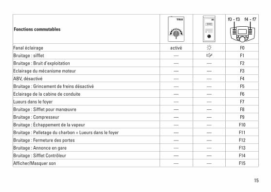
Fanal éclairage activé F0
Bruitage:sifflet — F1
Bruitage:Bruitd’exploitation — — F2
Eclairage du mécanisme moteur — — F3
ABV, désactivé — — F4
Bruitage:Grincementdefreinsdésactivé — — F5
Eclairage de la cabine de conduite — — F6
Lueurs dans le foyer — — F7
Bruitage:Siffletpourmanœuvre — — F8
Bruitage:Compresseur — — F9
Bruitage:Échappementdelavapeur — — F10
Bruitage:Pelletageducharbon+Lueursdanslefoyer — — F11
Bruitage:Fermeturedesportes — — F12
Bruitage:Annonceengare — — F13
Bruitage:SiffletContrôleur — — F14
Afficher/Masquerson — — F15

16
CV Signification Valeur DCC Valeur Parm. Usine
1 Adresse 1 – 127 3
2 Vitesse min 0 – 15 10
3 Temporisation d‘accélération 0 – 255 5
4 Temporisation de freinage 0 – 255 5
5 Vitesse maximale 0 – 127 109
17 Adresseétendue(partiesupérieure)(CV29,Bit5=1) 0 – 255 192
18 Adresseétendue(partieinférieure)(CV29,Bit5=1) 0 – 255 0
19 Adressepourlatraction(0=inactif,Valeur+128=directioninverse) 0 – 127 0
21 Mode traction, bit 0 à 7 =̂ F1 à F8 0 – 255 0
22 Mode traction; bit 0 à 1 =̂ FLf à FLr, Bit 2 à 5 =̂ F9 à F12 0 – 63 0
29
Bit0:inversiondepolarité,sensdemarcheBit1:Nombredecransdemarche14–28/126Bit2:ExploitationDCCaveczonedefreinage. DCC-, Selectrix et courant continu Bit5:tailled‘adresse7Bits/14Bits
0 – 255 6
52 Variation lumière 0 – 31 31
902 Volume 0 – 255 255

17
par Signification Valeur SX2 Valeur Parm. Usine
001 Adresse unités et décimales 0 – 99 1
002 Adresse centaines et milliers 0 – 99 10
011 Temporisation d’accélération 0 – 255 5
012 Temporisation de freinage 0 – 255 5
013 Vitesse maximale 0 – 127 109
014 Vitesse minimale 0 – 15 10
018 Vitesse de manoeuvre 0 – 127 109
021 Sections de freinage, 1 ou 2 0, 1 0
081 Variation lumière normale 0 – 31 31
082 Variation lumière alternative 0 – 31 15
Paramètresd’usinepourSX1:01à742,étendus:00-274

18

19
MINITRIX
66623
20
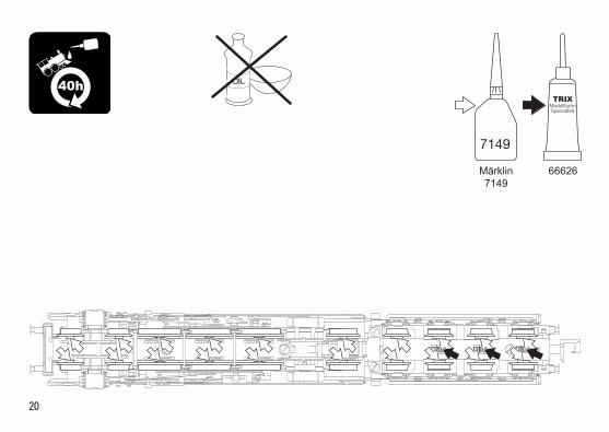
66626Märklin7149
7149
OIL 40h

216
5
2
7
10
5
8
1
5
9
3 4
Det
ails
der
Dar
stel
lung
kö
nnen
von
dem
Mod
ell
abw
eich
en.

22
15
12
12
19
17
20
15
16
11
5
4
19
18
14
14
13
Det
ails
der
Dar
stel
lung
kö
nnen
von
dem
Mod
ell
abw
eich
en.

23
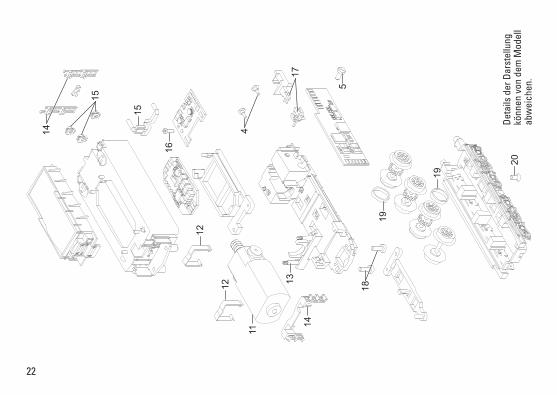
1 Windleitbleche E182 982 2 Lautsprecher E286 382 3 Laternen E265 002 4 Handstangen, Puffer E191 170 5 Schraube E19 8001 28 6 Gestänge links E282 899 7 Gestänge rechts E282 905 8 Drehgestell vorn E282 911 9 Drehgestell E282 917 10 Schraube E19 8049 28 11 Motor E257 634 12 Klammer E13 1481 00 13 Abdeckung E257 633 14 Treppe u. Leitern E288 473 15 Lampen u. Lichtkörper E265 003 16 Schraube E19 7094 28 17 Kupplung E198 503 18 Schraube E19 8035 28 19 Haftreifen E12 2273 00 20 Schraube E19 8326 28 Steckteile E309 463 Schutzrohr E22 3567 00
Hinweis:EinigeTeilewerdennurohneodermitandererFarbgebung angeboten. Teile, die hier nicht aufgeführt sind, können nur im Rahmen einer Reparatur im Märklin-Reparatur-Service repariert werden.
Note:Severalpartsareofferedunpaintedorinanothercolor. Parts that are not listed here can only be repaired by the Märklin repair service department.
Remarque:Certainsélémentssontproposésuniquementsans livrée ou dans une livrée différente. Les pièces ne figu-rant pas dans cette liste peuvent être réparées uniquement par le service de réparation Märklin.

Due to different legal requirements regarding electro-magnetic compatibility, this item may be used in the USA only after separate certification for FCC com-pliance and an adjustment if necessary. Use in the USA without this certification is not permitted and absolves us of any liability. If you should want such certification to be done, please contact us – also due to the additional costs incurred for this.
www.maerklin.com/en/imprint.html
Gebr. Märklin & Cie. GmbH Stuttgarter Straße 55 - 57 73033 Göppingen Germanywww.trix.de
285542/1117/Sm1EfÄnderungen vorbehalten
© Gebr. Märklin & Cie. GmbH

NL
Modell der Dampfl okomotive 01 202
16014

2
3
Índice PáginaInformaciones sobre el modelo real 5Aviso de seguridad 10Notas importantes 10Funciones 10Indicaciones para el funcionamiento digital 10Funciones conmutables 11Variables de Configuración (CVs) 12Mantenimiento y conservación 18Piezas de repuesto 21
Elenco del contenuto Pagina Informazioni sul prototipo 5Avvertenze per la sicurezza 14Avvertenze importanti 14Funzioni 14Istruzioni per la funzione digitale 14Funzioni commutabili 15Variabili di configurazione (CV) 16Assistenza e manutenzione 18Parti di ricambio 21
Inhoudsopgave PaginaInformatie van het voorbeeld 4Veiligheidsvoorschriften 6Belangrijke aanwijzing 6Functies 6Aanwijzingen voor digitale besturing 6Schakelbare functies 7Configuratie variabelen (CV’s) 8Onderhoud en handhaving 18Onderdelen 21

4
Informatie over het voorbeeldSneltreinlocomotieven waren door hun kracht, elegantie en snelheid altijd al de uitblinkers onder de stoomlocomotieven. Zo is de zware sneltreinlocomotief uit serie 01 zonder meer het toonbeeld van de Duitse geünificeerde stoomlocomotief. Deze reed net zo betrouwbaar voor representatieve sneltrei-nen als voor normale personentreinen.Tot 1938 werden bij verschillende Duitse fabrikanten in totaal 231 machines van serie 01 gebouwd. Daarbij kwamen nog 10 locomotieven van serie 02, die tussen 1937 en 1942 tot serie 01 werden omgebouwd. Na de Tweede Wereldoor-log bleven 165 locomotieven van serie 01 in de westelijke en 70 in de Russische bezettingszone, waarbij enkele machines vanwege zware beschadigingen buiten bedrijf moesten worden gesteld.Vanaf de jaren 50 bouwden beide Duitse spoorwegen de lo-comotieven meermaals om en werden deze aan de nieuwe inzetvereisten en de technische vooruitgang aangepast. In het westen werden bijvoorbeeld de grote Wagner-windleiplaten vervangen door de kleinere exemplaren van Witte, verhuisden de lucht- en toevoerpompen van de DB-locomotieven van de rookkamerput naar het midden van de ketel en verdween bij veel locomotieven het frontschort tussen bufferbalk en omloop.De inzet van serie 01 eindigde bij de DB midden jaren 70, bij de DR rolde deze begin jaren 80 het rangeerspoor op.

5
Informatie over het voorbeeldLas locomotoras de expreso, por su potencia, elegancia y velocidad, fueron siempre las estrellas entre las locomo-toras de vapor. Así, la locomotora de expreso pesada de la serie 01 constituye, sin duda alguna, la encarnación de la locomotora unificada alemana. Arrastraba con idéntica fia-bilidad tanto expresos de cierta categoría como los típicos trenes de viajeros.Hasta 1938, diferentes fabricantes alemanes fabricaron un total de 231 máquinas de la serie 01. A ello se añadieron 10 locomotoras más de la serie 02, las cuales se remodelaron entre 1937 y 1942 para convertirse en la serie 01. Tras la Segunda Guerra Mundial, 165 locomotoras de la serie 01 permanecían en las zonas occidentales y 70 en la zona de ocupación soviética, debiendo ser retiradas del servicio algunas de ellas debido a los graves daños sufridos en la contienda bélica.A partir de los años 50, ambas administraciones ferrovia-rias alemanas readaptaron varias veces esta locomotora, adecuándola a las nuevas condiciones de servicio así como a los avances técnicos. De este modo, en la zona Oc-cidental, las grandes chapas levantahumos Wagner fueron sustituidas por las pequeñas chapas levantahumos Witte, desplazándose la bomba de aire y de alimentación en las locomotoras de los DB del nicho de la cámara de humos ha-cia el centro de la caldera y desapareciendo en numerosas locomotoras el faldón frontal entre el travesaño portatopes y la plataforma perimetral de la locomotora.En los DB, el servicio de la serie 01 concluyó a mediados de los años 70 y en los DR esta serie fue a parar al apartadero a comienzos de los 80.
Informaciones sobre el modelo realLe locomotive per treni rapidi grazie alla loro potenza, eleganza e velocità furono da sempre le “stelle” tra le locomotive a vapore. E così la potente locomotiva per treni rapidi del Gruppo 01 costituisce proprio semplicemente la quintessenza delle locomotive tedesche unificate. Essa circolava altrettanto affidabilmente davanti a treni espressi di rappresentanza quanto in testa ai consueti treni pas-seggeri.Sino al 1938 vennero prodotte presso diversi costruttori tedeschi complessivamente 231 macchine del Gruppo 01. Oltre a ciò arrivarono ancora 10 locomotive del Gruppo 02, le quali tra il 1937 e il 1942 furono trasformate nel Gruppo 01. Dopo la 2ª guerra mondiale 165 locomotive del Gruppo 01 rimasero nella zona di occupazione occidentale e 70 nella zona di occupazione sovietica, mentre alcune dovettero essere radiate dal servizio a causa dei pesanti danneggiamenti.A partire dagli anni Cinquanta entrambe le Ferrovie tedesche trasformarono varie volte tale locomotiva e la adattarono alle nuove condizioni di impiego nonché al progresso tecnologico. Così nell’Ovest i grandi deflettori parafumo Wagner furono sostituiti dai piccoli Witte, il compressore dell’aria e pompa di alimentazione nel caso delle locomotive DB migrò via dalla nicchia della camera a fumo sino al centro della caldaia e nel caso di parecchie locomotive scomparve la carenatura frontale tra traversa dei respingenti e praticabili.L’impiego del Gruppo 01 ebbe termine presso la DB a metà degli anni Settanta, presso la DR essa andò a finire sul binario di accantonamento al principio degli Ottanta.
6
Veiligheidsvoorschriften• Delocmagalleenmeteendaarvoorbestemdbedrijfssys-
teem gebruikt worden.• Delocmagnietvanuitmeerdaneenstroomvoorziening
gelijktijdig gevoed worden.• Leesookaandachtigdeveiligheidsvoorschrifteninde
gebruiksaanwijzing van uw bedrijfssysteem. • Analoog14Volt=,digitaal22Volt~.• Voorhetconventionelebedrijfmetdelocdientde
aansluitrail te worden ontstoort. Hiervoor dient men de ontstoor-set 14972 te gebruiken. Voor het digitale bedrijf is deze ontstoor-set niet geschikt.
• Stelhetmodelnietblootaanindirectezonnestraling,sterke temperatuurwisselingen of hoge luchtvochtigheid.
• Degebruikteaansluitkabelmagmaximaal2meterlangzijn.• OPGEPAST! Functionele scherpe kanten en punten. • IngebouwdeLED’skomenovereenmetdelaserklasse1
volgens de norm EN 60825-1.
Belangrijke aanwijzing• Degebruiksaanwijzingendeverpakkingzijneenbe-
standdeel van het product en dienen derhalve bewaard en meegeleverd te worden bij het doorgeven van het product.
• VoorreparatiesenonderdelenkuntzichtotUwTrixhandelaar wenden.
• Vrijwaringengarantieovereenkomstighetbijgevoegdegarantiebewijs.
• Afdanken:www.maerklin.com/en/imprint.html
Algemene aanwijzing voor het vermijden van elektroma-gnetische storingen:Om een betrouwbaar bedrijf te garanderen is een per-manent, vlekkeloos wielas - rail contact van het voertuig noodzakelijk. Voer geen wijzigingen uit aan de stroomvoe-rende delen.
Functies• Ingebouwdeelektronicanaarkeuzetoepasbaarmet
conventionele gelijkstroomregelaar (max. ±12 volt), Trix Systems, Trix Selectrix (SX1) en Selectrix 2 (SX2) of digitaalsystemen volgens NMRA-norm.
• Automatischesysteemherkenningtussendigitaal-enanaloogbedrijf.
• Geenautomatischeherkenningtussendedigitale systemen.
• Drievoudigefrontverlichtingwisselendmetderijrichting.
Aanwijzingen voor digitale besturing • Bijhetvoorheteerstinbedrijfnemenineendigitaalsy-
steem (Sx1, Sx2 of DCC) moet de decoder ingesteld op dit digitale systeem. Hiervoor moet de decoder éénmaal in dat digitale systeem geprogrammeerd worden (bijv. het adres wijzigen).

7
Schakelbare functies
Frontsein aan F0
Geluid:fluit — F1
Geluid:bedrijfsgeluiden — — F2
Drijfwerkverlichting — — F3
ABV, uit — — F4
Geluid:piependeremmenuit — — F5
Cabineverlichting — — F6
Brandende fuur — — F7
Geluid:rangeerfluit — — F8
Geluid:luchtpomp — — F9
Geluid:stoomafblazen — — F10
Geluid:kolenscheppen+Brandendefuur — — F11
Geluid:deurensluiten — — F12
Geluid:stationsomroep — — F13
Geluid:conducteurfluit — — F14
Sounduit/inschakelen — — F15
2
7
1
6
STOP
PR
3
8
Sx
5
ON
Lz
4
9
1/2
Central- Control66800 f0 - f3 f4 - f7

8
CV Betekenis Waarde DCC Af fabriek
1 adres 1 – 127 3
2 Minimalgeschwindigkeit 0 – 15 10
3 optrekvertraging 0 – 255 5
4 afremvertraging 0 – 255 5
5 maximumsnelheid 0 – 127 109
17 uitgebreldadres(bovenstegedeelte)(CV29,Bit5=1) 0 – 255 192
18 uitgebreldadres(onderstegedeelte)(CV29,Bit5=1) 0 – 255 0
19 Adresvoortractie(0=inactief,Waarde+128=omgekeerderichting) 0 – 127 0
21 Tractie-modus ; bit 0 - 7 =̂ F1 - F8 0 – 255 0
22 Tractie-modus ; bit 0 - 1 =̂ FLf - FLr, bit 2 - 5 =̂ F9 - F12 0 – 63 0
29
Bit0:ompolingrijrichtingBit1:aantalrijstappen14–28/126Bit2:DCC-bedrijfmetafremtraject DCC-, Selectrix- en gelijkstroombedrijf Bit5:adresbereik7Bit/14Bit
0 – 255 6
52 Licht dimmend 0 – 31 31
902 Volume 0 – 255 255

9
par Betekenis Waarde SX2 Af fabriek
001 Adres enkel getal en tientallig in voerbaar 0 – 99 1
002 Adres honderd- en duizendtallig in voerbaar 0 – 99 10
011 Optrekvertraging 0 – 255 5
012 Afremvertraging 0 – 255 5
013 Maximale snelheid 0 – 127 109
014 Minimale snelheid 0 – 15 10
018 Snelheid bij rangeerbedrijf 0 – 127 109
021 Afrem secties; 1 of 2 0, 1 0
081 Licht normaal dimmend 0 – 31 31
082 Licht alternatief dimmend 0 – 31 15
FabrieksinstellingvoorSX1:01-742,uitgebreid:00-274
10
Aviso de seguridad• Lalocomotorasolamentedebefuncionarenelsistema
que le corresponda.• Laalimentacióndelalocomotoradeberárealizarse
desde una sola fuente de suminitro.• Observenecesariamentelosavisosdeseguridadindica-
dos en las instrucciones correspondientes a su sistema de funcionamiento.
• Analógicasmax.14Voltios=,digitalesmax.22voltios~• Paraelfuncionamientoconvencionaldelalocomotora
deben suprimirse las interferencias en la vía de conexión de la alimentación. Para ello debe emplearse el set supresor de interferencias 14972.
• Noexponerelmodeloenminiaturaalaradiaciónsolardirecta, a oscilaciones fuertes de temperatura o a una humedad del aire elevada.
• Elcabledeconexiónalavíautilizadodebetenerunalongitud máxima de 2 metros.
• ¡ATENCIÓN! Esquinas y puntas afiladas condicionadas a la función.
• LosLEDsincorporadoscorrespondenalaclasedeláser1 según la norma europea EN 60825-1.
Notas importantes• Lasinstruccionesdeempleoyelembalajeformanparte
íntegra del producto y, por este motivo, deben guardarse y entregarse junto con el producto en el caso de venderlo o transmitirlo a otro.
• Encasodeprecisarunareparaciónopiezasderecambio,rogamos ponerse en contacto con su distribuidor Trix.
• Responsabilidadygarantíaconformealdocumentodegarantía que se adjunta.
• Eliminación:www.maerklin.com/en/imprint.htmlConsejo general para evitar las interferencias electroma-gnéticas: Para garantizar un funcionamiento según las previsiones se requiere un contacto rueda-carril de los vehículos permanente sin anomalías. No realice ninguna modificación en piezas conductoras de la corriente.
Funciones• Electrónicaintegradaparafuncionamientoopcionalconel
aparato de conducción de corriente continua convencio-nal (máx. ±12 voltios), Trix Systems, Trix Selectrix (SX1) y Selectrix 2 (SX2) o sistemas digitales según norma NMRA.
• Detecciónautomáticadelsistemaentrelosmodosdigitaly analógico.
• Noexistereconocimientoautomáticodelsistemaentrelos sistemas digitales.
• Señaldecabezadetreslucesconalternanciaenfuncióndel sentido de la marcha.
Indicaciones para el funcionamiento digital• Enelfuncionamientoporprimeravezconunsistema
digital (SX1, SX2 o DCC), el decoder se debe configurar para este sistema digital. Para tal fin, se debe programar el decoder una vez en este sistema digital (p. ej., cambiar la dirección).

11
Funciones conmutables
Señal de cabeza en función del sentido de la marcha an F0
Ruido del silbido — F1
Ruido:Ruidodeexplotación — — F2
Iluminación de grupo propulsor — — F3
ABV, apagado — — F4
Ruido:Desconectarchirridodelosfrenos — — F5
Alumbrado interior de la cabina — — F6
Brasa del fuego — — F7
Ruido:Silbatodemaniobras — — F8
Ruido:Bombadeaire — — F9
Ruido:Purgarvapor — — F10
Ruido:Cargarcarbónconpala+Brasadelfuego — — F11
Ruido:Cerrarpuertas — — F12
Ruido:Locuciónhabladaenestaciones — — F13
Ruido:SilbatodeRevisor — — F14
Mostrar/ocultarsonido — — F15
2
7
1
6
STOP
PR
3
8
Sx
5
ON
Lz
4
9
1/2
Central- Control66800 f0 - f3 f4 - f7

12
CV Significado Valor DCC Preselec-ción
1 Códigos 1 – 127 3
2 Velocidad mínima 0 – 15 10
3 Arranque progresivo 0 – 255 5
4 Frenado progresivo 0 – 255 5
5 Velocidad máxima 0 – 127 109
17 Direcciónampliada(partesuperior)(CV29,Bit5=1) 0 – 255 192
18 Direcciónampliada(parteinferior)(CV29,Bit5=1) 0 – 255 0
19 Direccióndetracción(0=inactiva,valor+128=sentidodemarchainverso) 0 – 127 0
21 Modo Tracción; bit 0 – 7 =̂ F1 – F8 0 – 255 0
22 Modo Tracción; bit 0 – 1 =̂ FLf – FLr, bit 2 – 5 =̂ F9 – F12 0 – 63 0
29
Bit0:CambiodesentidodemarchaBit1:Númerodenivelesdemarcha14-28/126Bit2:ModoDCCcontramodefrenado Modo DCC, Selectrix y corriente continua Bit5:Alcancededirecciones7bits/14bits
0 – 255 6
52 Regulación de intensidad de luz 0 – 31 31
902 Volumen 0 – 255 255

13
par Significado Valor SX2 De fábrica
001 Unidadydecenadedirección 0 – 99 1
002 Centena y millar de dirección 0 – 99 10
011 Retardo de arranque 0 – 255 5
012 Retardo de frenado 0 – 255 5
013 Velocidad máxima 0 – 127 109
014 Velocidad mínima 0 – 15 10
018 Velocidad de marcha de maniobras 0 – 127 109
021 Tramos de frenado; 1 o 2 0, 1 0
081 Regulación de intensidad de luz normal 0 – 31 31
082 Regulación de luz alternativa 0 – 31 15
ConfiguracióndefábricaparaSX1:01-742,ampliada:00-274

14
Avvertenze per la sicurezza• Talelocomotivadevevenireimpiegatasoltantoconun
sistema di esercizio prestabilito a questo scopo.• Lalocomotivanondevevenirealimentatanellostesso
tempo con più di una sorgente di potenza.• Vogliateprestareassolutamenteattenzionealleavverten-
ze di sicurezza nelle istruzioni di impiego per il Vostro sistema di funzionamento.
• Analogicomax.14Volt=,digitalemax.22Volt~• Perilfunzionamentotradizionaledellalocomotivailbina-
rio di alimentazione deve essere protetto dai disturbi. A tale scopo si deve impiegare il corredo antidisturbi 14972. Tale corredo antidisturbi non è adatto per il funzionamen-to Digital.
• Nonesponetetalemodelloadalcunirraggiamentosolarediretto, a forti escursioni di temperatura oppure a elevata umidità dell’aria.
• Ilcavodicollegamentoalbinarioimpiegatodeveesserelungo al massimo soltanto 2 metri.
• AVVERTENZA! Per motivi funzionali i bordi e le punte sono spigolosi.
• ILEDincorporaticorrispondonoallacategoriadilaser1secondo la Norma EN 60825-1.
Avvertenze importanti• Leistruzionidiimpiegoel’imballaggiocostituisconoun
componente sostanziale del prodotto e devono pertanto venire conservati nonché consegnati insieme in caso di ulteriore cessione del prodotto.
• Perleriparazioniolepartidiricambio,contrattareilrivenditore Trix.
• Prestazionidigaranziaegaranziainconformitàall’accluso certificato di garanzia.
• Smaltimento:www.maerklin.com/en/imprint.htmlAvvertenza generale per la prevenzione di disturbi elettro-magnetici: Per garantire l’esercizio conforme alla destinazione è necessario un contatto ruota-rotaia dei rotabili permanente, esente da interruzioni. Non eseguite alcuna modificazione ai componenti conduttori di corrente.
Funzioni• Moduloelettronicoincorporatoperilfunzionamentoa
scelta con regolatore di marcia tradizionale a corrente continua (max. ±12 volt), Trix Systems, Trix Selectrix (SX1) e Selectrix 2 (SX2) oppure con sistemi digitali secondo le norme NMRA.
• RiconoscimentoautomaticodelsistematraesercizioDigital ed analogico.
• Nessunriconoscimentoautomaticodelsistematraisistemi digitali.
• Segnaleditestaatrefanalicommutatisecondoilsensodi marcia.
Istruzioni per la funzione digitale• Almomentodelprimofunzionamentoinundatosistema
digitale (SX1, SX2 oppure DCC) il Decoder deve venire impostato su questo sistema digitale. A tale scopo il De-coder si deve programmare una volta in questo sistema digitale (ad es. modificare l’indirizzo).

15
Funzioni commutabili
Segnale di testa dipendente dal senso di marcia an F0
Rumore:Fischio — F1
Rumore:rumoridiesercizio — — F2
Illuminazione del rodiggio — — F3
ABV, spento — — F4
Rumore:stridoredeifreniescluso — — F5
Illuminazione della cabina — — F6
Fuoco dei carboni — — F7
Rumore:Fischiodimanovra — — F8
Rumore:compressoredell’aria — — F9
Rumore:scaricodelvapore — — F10
Rumore:Spalaturadelcarbone+Fuocodeicarboni — — F11
Rumore:chiusuradelleporte — — F12
Rumore:annunciodistazione — — F13
Rumore:Fischiodicapotreno — — F14
Sovrapposizione/evanescenzaeffettosonoro — — F15
2
7
1
6
STOP
PR
3
8
Sx
5
ON
Lz
4
9
1/2
Central- Control66800 f0 - f3 f4 - f7

16
CV Significato Valore DCC Di fabbrica
1 Indirizzo 1 – 127 3
2 Velocità minima 0 – 15 10
3 Ritardo di avviamento 0 – 255 5
4 Ritardo di frenatura 0 – 255 5
5 Velocità massima 0 – 127 109
17 Indirizzoampliato(partesuperiore)(CV29,Bit5=1) 0 – 255 192
18 Indirizzoampliato(parteinferiore)(CV29,Bit5=1) 0 – 255 0
19 Indirizzotraz.multipla(0=inattiva,valore+128=sensodimarciainverso) 0 – 127 0
21 Modalità di trazione; Bit 0 – 7 =̂ F1 – F8 0 – 255 0
22 Modalità di trazione; Bit 0 – 1 =̂ FLf – FLr, Bit 2 – 5 =̂ F9 – F12 0 – 63 0
29
Bit0:inversionepolaritàdelsensodimarciaBit1:numerogradazionidimarcia14-28/126Bit2:EsercizioDCCcontrattadifrenatura Esercizio DCC, Selectrix e corrente continua Bit5:Ampiezzaindirizzo7Bit/14Bit
0 – 255 6
52 Attenuazione fanali 0 – 31 31
902 Volume 0 – 255 255

17
par Significato Valore SX2 di fabbrica
001 Cifre unità e decine dell’indirizzo 0 – 99 1
002 Cifre centinaia e migliaia dell’indirizzo 0 – 99 10
011 Ritardo di avviamento 0 – 255 5
012 Ritardo di frenatura 0 – 255 5
013 Velocità massima 0 – 127 109
014 Velocità minima 0 – 15 10
018 Velocità andatura di manovra 0 – 127 109
021 Tratta di frenatura; 1 oppure 2 0, 1 0
081 Attenuazione fanali normale 0 – 31 31
082 Attenuazione fanali alternativa 0 – 31 15
ImpostazionedifabbricaperSX1:01-742,esteso:00-274

18

19
MINITRIX
66623

20
66626Märklin7149
7149
OIL 40h

216
5
2
7
10
5
8
1
5
9
3 4
Det
ails
der
Dar
stel
lung
kö
nnen
von
dem
Mod
ell
abw
eich
en.
22
15
12
12
19
17
20
15
16
11
5
4
19
18
14
14
13
Det
ails
der
Dar
stel
lung
kö
nnen
von
dem
Mod
ell
abw
eich
en.

23
Opmerking:enkeledelenwordenalleenkleurloosofineenandere kleur aangeboden. Delen die niet in de in de lijst voorkomen, kunnen alleen via een reparatie in het Märklin-service-centrumhersteld/vervangenworden.
Nota:algunaspiezasestándisponiblessólosinoconotrocolor. Las piezas que no figuran aquí pueden repararse únicamente en el marco de una reparación en el servicio de reparación de Märklin.
Avvertenza:Alcunielementivengonopropostisolosenzao con differente colorazione. I pezzi che non sono qui spe-cificati possono venire riparati soltanto nel quadro di una riparazione presso il Servizio Riparazioni Märklin.
1 Windleitbleche E182 982 2 Lautsprecher E286 382 3 Laternen E265 002 4 Handstangen, Puffer E191 170 5 Schraube E19 8001 28 6 Gestänge links E282 899 7 Gestänge rechts E282 905 8 Drehgestell vorn E282 911 9 Drehgestell E282 917 10 Schraube E19 8049 28 11 Motor E257 634 12 Klammer E13 1481 00 13 Abdeckung E257 633 14 Treppe u. Leitern E288 473 15 Lampen u. Lichtkörper E265 003 16 Schraube E19 7094 28 17 Kupplung E198 503 18 Schraube E19 8035 28 19 Haftreifen E12 2273 00 20 Schraube E19 8326 28 Steckteile E309 463 Schutzrohr E22 3567 00

Due to different legal requirements regarding electro-magnetic compatibility, thisitemmaybeusedintheUSAonlyafterseparatecertificationforFCCcom-pliance and an adjustment if necessary. UseintheUSAwithoutthiscertificationisnotpermittedandabsolvesusofanyliability. If you should want such certification to be done, please contact us – also due to the additional costs incurred for this.
www.maerklin.com/en/imprint.html
Gebr. Märklin & Cie. GmbH Stuttgarter Straße 55 - 57 73033 Göppingen Germanywww.trix.de
285543/1117/Sm1EfÄnderungen vorbehalten
© Gebr. Märklin & Cie. GmbH