Embed Size (px)
Citation preview
HALFEN SP INST_SP 04/19
Assembly Instructions • Montageanleitung • Notice d‘utilisation • Instrukcja montażu • Montážní návod • Montagehandleiding
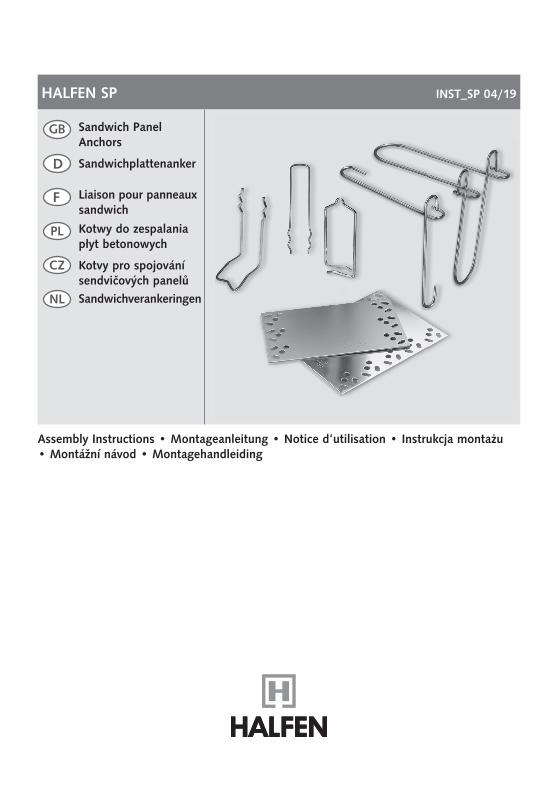
Sandwich Panel Anchors
D
Kotvy pro spojování sendvičových panelůSandwichverankeringen
CZ
NL
Kotwy do zespalania płyt betonowych
PL
Liaison pour panneaux sandwich
F
Sandwichplattenanker
GB
2
HALFEN SP Assembly InstructionsD
euts
chEn
glis
hFr
ança
isPo
lski
Čes
kyN
eder
land
s
© 2019 HALFEN · INST_SP 04/19 · www.halfen.com
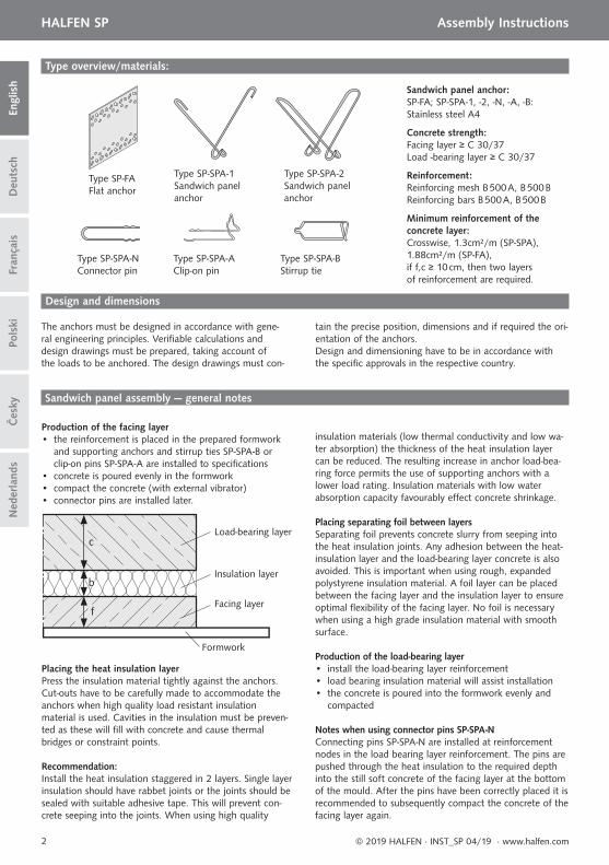
Type overview/materials:
Type SP-SPA-N Connector pin
Type SP-SPA-A Clip-on pin
Type SP-SPA-B Stirrup tie
Type SP-FA Flat anchor
Type SP-SPA-2 Sandwich panel anchor
Type SP-SPA-1 Sandwich panel anchor
Sandwich panel assembly — general notes
Design and dimensions
Production of the facing layer• the reinforcement is placed in the prepared formwork
and supporting anchors and stirrup ties SP-SPA-B or clip-on pins SP-SPA-A are installed to specifi cations
• concrete is poured evenly in the formwork• compact the concrete (with external vibrator)• connector pins are installed later.
Sandwich panel anchor:SP-FA; SP-SPA-1, -2, -N, -A, -B: Stainless steel A4
Concrete strength:Facing layer ≥ C 30/37Load -bearing layer ≥ C 30/37
Reinforcement:Reinforcing mesh B 500 A, B 500 BReinforcing bars B 500 A, B 500 B
Minimum reinforcement of the concrete layer:Crosswise, 1.3cm²/m (SP-SPA), 1.88cm²/m (SP-FA),if f,c ≥ 10 cm, then two layers of reinforcement are required.
Load-bearing layer
Insulation layer
Formwork
Facing layer
c
b
f
Placing the heat insulation layerPress the insulation material tightly against the anchors. Cut-outs have to be carefully made to accommodate the anchors when high quality load resistant insulation material is used. Cavities in the insulation must be preven-ted as these will fi ll with concrete and cause thermal bridges or constraint points.
Recommendation:Install the heat insulation staggered in 2 layers. Single layer insulation should have rabbet joints or the joints should be sealed with suitable adhesive tape. This will prevent con-crete seeping into the joints. When using high quality
insulation materials (low thermal conductivity and low wa-ter absorption) the thickness of the heat insulation layer can be reduced. The resulting increase in anchor load-bea-ring force permits the use of supporting anchors with a lower load rating. Insulation materials with low water absorption capacity favourably eff ect concrete shrinkage.
Placing separating foil between layersSeparating foil prevents concrete slurry from seeping into the heat insulation joints. Any adhesion between the heat-insulation layer and the load-bearing layer concrete is also avoided. This is important when using rough, expanded polystyrene insulation material. A foil layer can be placed between the facing layer and the insulation layer to ensure optimal fl exibility of the facing layer. No foil is necessary when using a high grade insulation material with smooth surface.
Production of the load-bearing layer• install the load-bearing layer reinforcement• load bearing insulation material will assist installation• the concrete is poured into the formwork evenly and compacted
Notes when using connector pins SP-SPA-N Connecting pins SP-SPA-N are installed at reinforcement nodes in the load bearing layer reinforcement. The pins are pushed through the heat insulation to the required depth into the still soft concrete of the facing layer at the bottom of the mould. After the pins have been correctly placed it is recommended to subsequently compact the concrete of the facing layer again.
The anchors must be designed in accordance with gene-ral engineering principles. Verifi able calculations and design drawings must be prepared, taking account of the loads to be anchored. The design drawings must con-
tain the precise position, dimensions and if required the ori-entation of the anchors.Design and dimensioning have to be in accordance with the specifi c approvals in the respective country.
d a a d
L
f
b
H
3
HALFEN SP Assembly Instructions
Deu
tsch
Engl
ish
Pols
kiFr
ança
isČ
esky
Ned
erla
nds
© 2019 HALFEN · INST_SP 04/19 · www.halfen.com
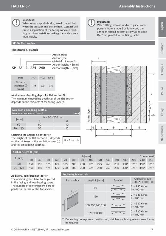
Important:When lifting precast sandwich panel com-ponents from a mould or formwork, the adhesion should be kept as low as possible. Don’t lift parallel to the tilting table!
Important: When using a spud-vibrator, avoid contact bet-ween the vibrator and the anchors. Contact will cause a separation of the facing concrete resul-ting in colour variations making the anchor con-tours visible.
SP-FA Flat anchor
Minimum embedding depth for fl at anchor FA The minimum embedding depth (a) of the fl at anchor depends on the thickness of the facing layer (f).
Type FA-1 FA-2 FA-3
Material thickness
[mm]1.5 2.0 3.0
H ≥ 2 × a + b
Selecting the anchor height for FAThe height of the fl at anchor (H) depends on the thickness of the insulation layer (b) and the embedding depth (a).
SP - FA - 2 - 225 - 240
Article groupAnchor typeMaterial thickness Anchor height H [mm]Anchor length L [mm]
Identifi cation, example
Load
-bea
ring
laye
r
Faci
ng la
yerMinimum embedding depth a
Minimum concrete cover d [mm]
f [mm]b = 30 - 250 mm
a d60 50 10
70 - 120 55 15
Anchor height H [mm]
f [mm]b [mm] * on request
30 40 50 60 70 80 90 100 120 140 160 180 200 230 250
60 150 150 175 175 175 200 200 225 225 260 280 300* 325* 350* 375*70 - 120 150 150 175 175 200 200 200 225 260 260 280 300* 325* 350* 375*
Additional reinforcement for FAThe anchoring bars have to be placed in the facing and load-bearing layers. The number of reinforcement bars de-pends on the size of the fl at anchor.
Anchoring in concrete
Flat anchor Length L [mm] SymbolAnchoring bars
B 500 A, B 500 B
L
H
802 × 4 Ø 6 mml = 400 mm
1202 × 5 Ø 6 mml = 400 mm
160,200,240,2802 × 6 Ø 6 mml = 400 mm
320,360,4002 × 7 Ø 6 mml = 400 mm
Depending on exposure classifi cation, stainless anchoring reinforcement may be required.
3
2
30
30
30
30 1
b
sr
f
L
aV aT c
H
4
HALFEN SP Assembly InstructionsD
euts
chEn
glis
hFr
ança
isPo
lski
Čes
kyN
eder
land
s
© 2019 HALFEN · INST_SP 04/19 · www.halfen.com
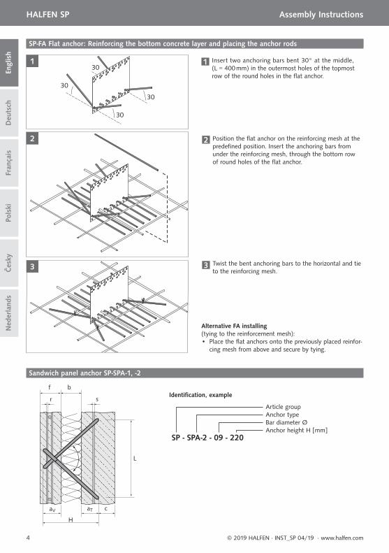
SP-FA Flat anchor: Reinforcing the bottom concrete layer and placing the anchor rods
1 Insert two anchoring bars bent 30° at the middle, (L = 400 mm) in the outermost holes of the topmost row of the round holes in the fl at anchor.
2 Position the fl at anchor on the reinforcing mesh at the predefi ned position. Insert the anchoring bars from under the reinforcing mesh, through the bottom row of round holes of the fl at anchor.
3 Twist the bent anchoring bars to the horizontal and tie to the reinforcing mesh.
Alternative FA installing(tying to the reinforcement mesh):• Place the fl at anchors onto the previously placed reinfor-
cing mesh from above and secure by tying.
SP - SPA-2 - 09 - 220
Article groupAnchor typeBar diameter ØAnchor height H [mm]
Identifi cation, example
Sandwich panel anchor SP-SPA-1, -2
Load-bearing layer
Facing layer
Øs
Ør
lslr
5
HALFEN SP Assembly Instructions
Deu
tsch
Engl
ish
Pols
kiFr
ança
isČ
esky
Ned
erla
nds
© 2019 HALFEN · INST_SP 04/19 · www.halfen.com
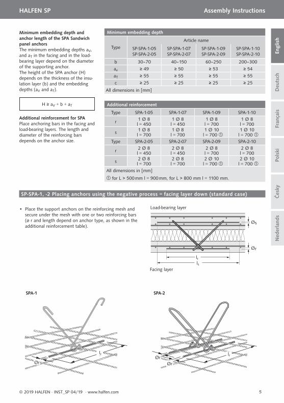
Minimum embedding depth and anchor length of the SPA Sandwich panel anchorsThe minimum embedding depths aV, and aT in the facing and in the load-bearing layer depend on the diameter of the supporting anchor.The height of the SPA anchor (H) depends on the thickness of the insu-lation layer (b) and the embedding depths (aV and aT).
Additional reinforcement for SPAPlace anchoring bars in the facing and load-bearing layers. The length and diameter of the reinforcing bars depends on the anchor size.
Minimum embedding depth
Type
Article name
SP-SPA-1-05 SP-SPA-2-05
SP-SPA-1-07 SP-SPA-2-07
SP-SPA-1-09SP-SPA-2-09
SP-SPA-1-10SP-SPA-2-10
b 30–70 40–150 60–250 200–300
av ≥ 49 ≥ 50 ≥ 53 ≥ 54
aT ≥ 55 ≥ 55 ≥ 55 ≥ 55
c ≥ 25 ≥ 25 ≥ 25 ≥ 25
All dimensions in [mm]
Additional reinforcement
Type SPA-1-05 SPA-1-07 SPA-1-09 SPA-1-10
r 1 Ø 8 1 Ø 8 1 Ø 8 1 Ø 8l = 450 l = 450 l = 700 l = 700
s 1 Ø 8 1 Ø 8 1 Ø 10 1 Ø 10l = 700 l = 700 l = 700 l = 700
Type SPA-2-05 SPA-2-07 SPA-2-09 SPA-2-10
r 2 Ø 8 2 Ø 8 2 Ø 8 2 Ø 8l = 450 l = 450 l = 700 l = 700
s 2 Ø 8 2 Ø 8 2 Ø 10 2 Ø 10l = 700 l = 700 l = 700 l = 700
All dimensions in [mm]
for L > 500 mm l = 900 mm, for L > 800 mm l = 1100 mm.
H ≥ aV + b + aT
SP-SPA-1, -2 Placing anchors using the negative process = facing layer down (standard case)
• Place the support anchors on the reinforcing mesh and secure under the mesh with one or two reinforcing bars (ø r and length depend on anchor type, as shown in the additional reinforcement table).
lrlr
Ør
SPA-1
lrØrØr
SPA-2
Faci
ng la
yer
Load
-bea
ring
laye
r
f ≥ 60 b ≥ 100
≥ 5≥ 30 * ≥ 30 * ≥ 55
av
aT
Faci
ng la
yer
Load
-bea
ring
laye
r
f ≥ 60 b ≥ 100
≥ 50≥ 5 ≥ 55 ≥ 50av aT
Faci
ng la
yer
Load
-bea
ring
laye
r
f ≥ 60 b ≥ 100
≥ 35≥ 30 * ≥ 30 * ≥ 65
av
aT
6
HALFEN SP Assembly InstructionsD
euts
chEn
glis
hFr
ança
isPo
lski
Čes
kyN
eder
land
s
© 2019 HALFEN · INST_SP 04/19 · www.halfen.com
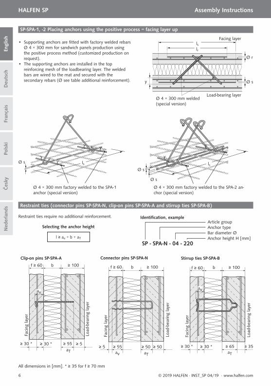
SP-SPA-1, -2 Placing anchors using the positive process = facing layer up
• Supporting anchors are fi tted with factory welded rebars Ø 4 × 300 mm for sandwich panels production using the positive process method (customized production on request).
• The supporting anchors are installed in the top reinforcing mesh of the loadbearing layer. The welded bars are wired to the mat and secured with the secondary rebars (Ø see table additional reinforcement).
Ø 4 × 300 mm factory welded to the SPA-1 anchor (special version)
Ø s
Ø 4 × 300 mm factory welded to the SPA-2 an-chor (special version)
Ø s
Ø s
Ø 4 × 300 mm welded (special version)
Facing layer
Load-bearing layer
lrls
Ø r
Ø sy
lsls
Restraint ties require no additional reinforcement.
Restraint ties (connector pins SP-SPA-N, clip-on pins SP-SPA-A and stirrup ties SP-SPA-B)
Connector pins SP-SPA-N Stirrup ties SP-SPA-B Clip-on pins SP-SPA-A
Selecting the anchor height
l ≥ av + b + aT
SP - SPA-N - 04 - 220
Article groupAnchor typeBar diameter ØAnchor height H [mm]
Identifi cation, example
All dimensions in [mm]. * ≥ 35 for f ≥ 70 mm
7
HALFEN SP Assembly Instructions
Deu
tsch
Engl
ish
Pols
kiFr
ança
isČ
esky
Ned
erla
nds
© 2019 HALFEN · INST_SP 04/19 · www.halfen.com
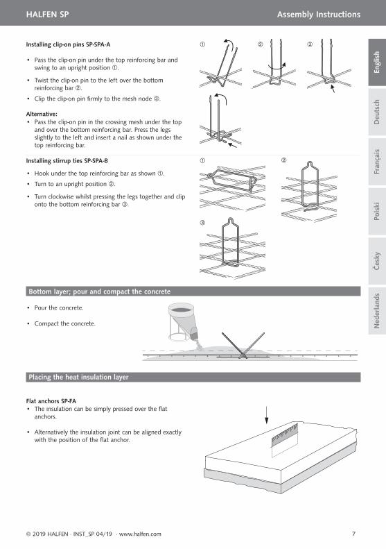
• Hook under the top reinforcing bar as shown .
• Turn to an upright position .
• Turn clockwise whilst pressing the legs together and clip onto the bottom reinforcing bar .
• Pass the clip-on pin under the top reinforcing bar and swing to an upright position .
• Twist the clip-on pin to the left over the bottom reinforcing bar .
• Clip the clip-on pin fi rmly to the mesh node .
• Pass the clip-on pin in the crossing mesh under the top and over the bottom reinforcing bar. Press the legs slightly to the left and insert a nail as shown under the top reinforcing bar.
Installing clip-on pins SP-SPA-A
Installing stirrup ties SP-SPA-B
Alternative:
Placing the heat insulation layer
Flat anchors SP-FA • The insulation can be simply pressed over the fl at anchors.
• Alternatively the insulation joint can be aligned exactly with the position of the fl at anchor.
• Pour the concrete.
• Compact the concrete.
Bottom layer; pour and compact the concrete
8
HALFEN SP Assembly InstructionsD
euts
chEn
glis
hFr
ança
isPo
lski
Čes
kyN
eder
land
s
© 2019 HALFEN · INST_SP 04/19 · www.halfen.com
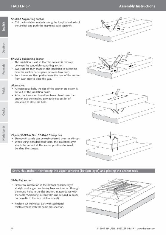
SP-FA Flat anchor: Reinforcing the upper concrete (bottom layer) and placing the anchor rods
SP-FA Flat anchor
• Similar to installation in the bottom concrete layer, straight and angled anchoring bars are inserted through the round holes in the fl at anchors in accordance with the table "Anchoring in concrete" and secured in positi on (wire-tie to the slab reinforcement).
• Replace cut individual bars with additional reinforcement with the same cross-section.
SP-SPA-1 Supporting anchor • Cut the insulation material along the longitudinal axis of the anchor and push the segments back together.
SP-SPA-2 Supporting anchor• The insulation is cut so that the cut-end is midway between the sandwich supporting anchor. • Two cuts are then made in the insulation to accommo date the anchor bars (space between two bars).• Both halves are then pushed over the bars of the anchor from each side to close the gap.
Alternative: • A rectangular hole, the size of the anchor projection is cut out of the insulation board.• After the insulation board has been placed over the anchor, use the smaller, previously cut out bit of insulation to close the hole.
Clip-on SP-SPA-A Pins, SP-SPA-B Stirrup ties• Styropor® panels can be easily pressed over the stirrups.• When using extruded hard foam, the insulation layer should be cut out at the anchor positions to avoid bending the stirrups.
9
HALFEN SP Assembly Instructions
Deu
tsch
Engl
ish
Pols
kiFr
ança
isČ
esky
Ned
erla
nds
© 2019 HALFEN · INST_SP 04/19 · www.halfen.com
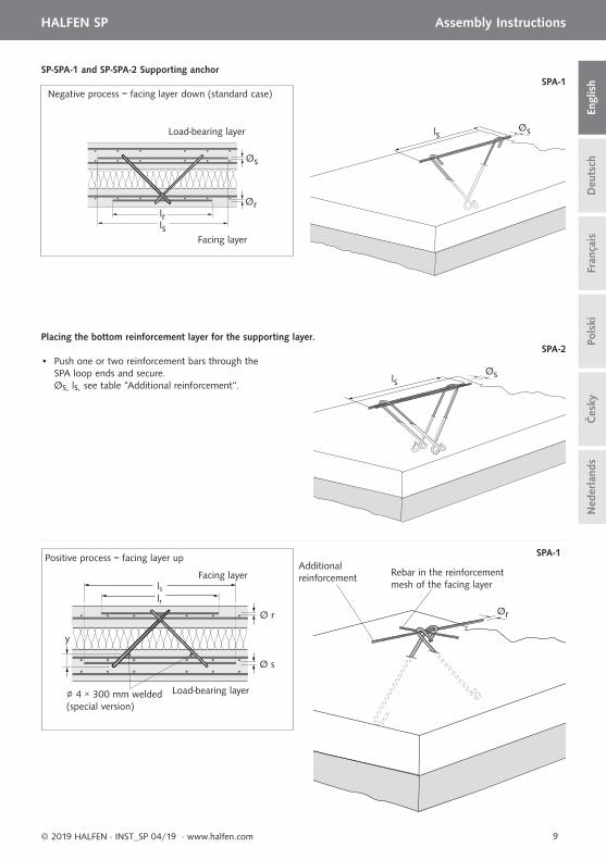
Positive process = facing layer upAdditional reinforcement Rebar in the reinforcement
mesh of the facing layer
• Push one or two reinforcement bars through the SPA loop ends and secure. Øs, ls, see table “Additional reinforcement“.
lsØs
Ør
Placing the bottom reinforcement layer for the supporting layer.
SPA-1
SPA-2
∅ 4 × 300 mm welded (special version)
Load-bearing layer
Facing layer
lrls
Ø r
Ø s
y
lsØs
SPA-1Negative process = facing layer down (standard case)
Load-bearing layer
Facing layer
lrls
Øs
Ør
SP-SPA-1 and SP-SPA-2 Supporting anchor
10
HALFEN SP Assembly InstructionsD
euts
chEn
glis
hFr
ança
isPo
lski
Čes
kyN
eder
land
s
© 2019 HALFEN · INST_SP 04/19 · www.halfen.com
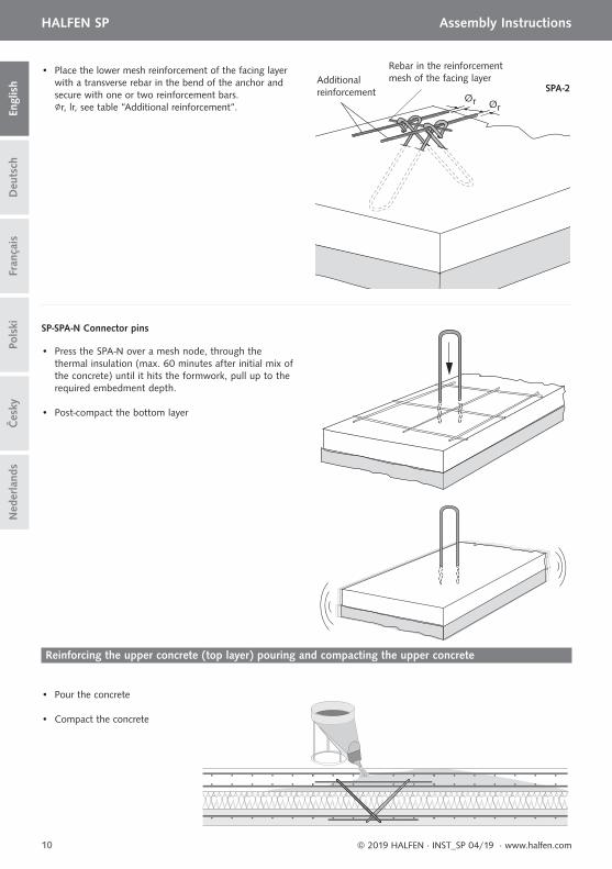
Additional reinforcement
Rebar in the reinforcement mesh of the facing layer
• Place the lower mesh reinforcement of the facing layer with a transverse rebar in the bend of the anchor and secure with one or two reinforcement bars. ∅r, lr, see table “Additional reinforcement“.
Ør Ør
SPA-2
• Press the SPA-N over a mesh node, through the thermal insulation (max. 60 minutes after initial mix of the concrete) until it hits the formwork, pull up to the required embedment depth.
SP-SPA-N Connector pins
• Post-compact the bottom layer
• Pour the concrete
• Compact the concrete
Reinforcing the upper concrete (top layer) pouring and compacting the upper concrete
11
HALFEN SP Montageanleitung
Deu
tsch
Engl
ish
Pols
kiFr
ança
is
© 2019 HALFEN · INST_SP 04/19 · www.halfen.com
Čes
kyN
eder
land
s
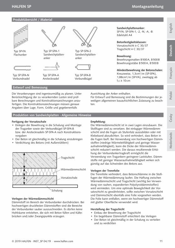
Produktübersicht / Material
Typ SP-SPA-N Verbundnadel
Typ SP-SPA-A Anstecknadel
Typ SP-SPA-B Verbundbügel
Typ SP-FA Flachanker
Typ SP-SPA-2 Sandwichplatten-anker
Typ SP-SPA-1 Sandwichplatten-anker
Produktion von Sandwichplatten - Allgemeine Hinweise
Entwurf und Bemessung
Fertigung der Vorsatzschale• Einlegen der Bewehrung in die Schalung und Montage der Traganker sowie der Verbundbügel SP-SPA-B bzw. der Anstecknadeln SP-SPA-A nach Konstruktions- vorgaben• Der Beton ist gleichmäßig in die Schalung einzubringen• Verdichtung des Betons (mit Außenrüttlern)
Sandwichplattenanker:SP-FA; SP-SPA-1, -2, -N, -A, -B: Edelstahl A4
Betonfestigkeitsklassen:Vorsatzschicht ≥ C 30/37Tragschicht ≥ C 30/37
Bewehrung:Bewehrungsmatten B 500 A, B 500 BBewehrungsstäbe B 500 A, B 500 B
Mindestbewehrung der Betonschalen:Kreuzweise, 1,3cm²/m (SP-SPA), 1,88cm²/m (SP-FA), zweilagig ab f,c ≥ 10 cm
Tragschicht
Wärmedämmschicht
Schalung
Vorsatzschale
c
b
f
Die Verankerungen sind ingenieurmäßig zu planen. Unter Berücksichtigung der zu verankernden Lasten sind prüf-bare Berechnungen und Konstruktionszeichnungen anzu-fertigen. Die Konstruktionszeichnungen müssen genaue Angaben über Lage, Form, Größe und gegebenenfalls
Ausrichtung der Anker enthalten.Für Entwurf und Bemessung sind die Bestimmungen der je-weiligen allgemeinen bauaufsichtlichen Zulassung zu beach-ten.
Verlegen der WärmedämmschichtDämmstoff im Bereich der Verbundanker durchdrücken. Bei hochwertigen druckfesten Dämmstoff en sind die Bereiche der Verbundanker sauber auszuschneiden. Es dürfen keine Hohlräume entstehen, die sich mit Beton füllen und Kälte-brücken und/oder Zwangspunkte erzeugen.
Empfehlung:Die Wärmedämmschicht ist in zwei Lagen einzubauen. Die Stoßfugen sind zu versetzen. Bei einlagiger Wärmedämm-schicht sind die Fugen als Stufenfalz auszubilden oder mit Klebeband abzudichten. So wird verhindert, dass Beton in die Fugen läuft. Bei Verwendung von hochwertigen Dämm-stoff en (niedrige Wärmeleitfähigkeit und geringe Wasser-aufnahmefähigkeit), kann die Dicke der Wärmedämm-schicht reduziert werden. Die daraus resultierende Erhö-hung der Verbundankertragkraft ermöglicht die Verwendung von Tragankern geringerer Laststufen. Dämm-stoff e mit geringer Wasseraufnahmefähigkeit wirken sich günstig auf das Schwinden des Betons aus.
Verlegen der TrennfolieDie Trennfolie verhindert, dass Betonschlämme in die Stoß-fugen der Wärmedämmung laufen. Die Haftung zwischen Wärmedämmschicht und Tragschicht (wichtig bei Verwen-dung von rauhen, expandierten Polystyroldämmstoff en) wird vermieden. Um eine optimale Beweglichkeit der Vor-satzschicht zu gewährleisten, sollte zwischen Vorsatzschicht und Dämmschicht ebenfalls eine Folie vorgesehen werden. Die Folie kann entfallen, wenn ein hochwertiger Dämmstoff mit glatter Oberfl äche verwendet wird.
Herstellung der Tragschicht• Einbau der Bewehrung der Tragschicht• Ein begehbarer Dämmstoff erleichtert das Verlegen• Der Beton ist gleichmäßig in der Schalung zu verteilen
und zu verdichten
12
HALFEN SP Montageanleitung D
euts
chEn
glis
hFr
ança
isPo
lski
© 2019 HALFEN · INST_SP 04/19 · www.halfen.com
Čes
kyN
eder
land
s
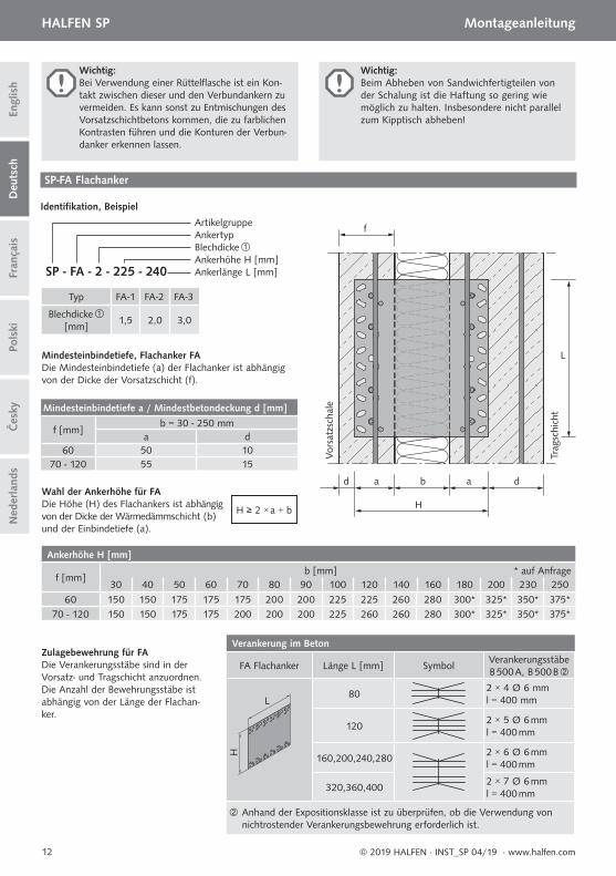
Wichtig:Bei Verwendung einer Rüttelfl asche ist ein Kon-takt zwischen dieser und den Verbundankern zu vermeiden. Es kann sonst zu Entmischungen des Vorsatzschichtbetons kommen, die zu farblichen Kontrasten führen und die Konturen der Verbun-danker erkennen lassen.
Wichtig:Beim Abheben von Sandwichfertigteilen von der Schalung ist die Haftung so gering wiemöglich zu halten. Insbesondere nicht parallel zum Kipptisch abheben!
SP-FA Flachanker
Mindesteinbindetiefe, Flachanker FA Die Mindesteinbindetiefe (a) der Flach anker ist abhängig von der Dicke der Vorsatzschicht (f).
Typ FA-1 FA-2 FA-3
Blechdicke [mm]
1,5 2,0 3,0
H ≥ 2 × a + b
Wahl der Ankerhöhe für FADie Höhe (H) des Flachankers ist abhängig von der Dicke der Wärmedämmschicht (b) und der Einbindetiefe (a).
SP - FA - 2 - 225 - 240
ArtikelgruppeAnkertypBlechdickeAnkerhöhe H [mm]Ankerlänge L [mm]
Identifi kation, Beispiel
Mindesteinbindetiefe a / Mindestbetondeckung d [mm]
f [mm]b = 30 - 250 mm
a d60 50 10
70 - 120 55 15
d a a d
L
f
b
H
Trag
schi
cht
Vor
satz
scha
le
Ankerhöhe H [mm]
f [mm]b [mm] * auf Anfrage
30 40 50 60 70 80 90 100 120 140 160 180 200 230 250
60 150 150 175 175 175 200 200 225 225 260 280 300* 325* 350* 375*70 - 120 150 150 175 175 200 200 200 225 260 260 280 300* 325* 350* 375*
Zulagebewehrung für FADie Verankerungsstäbe sind in der Vorsatz- und Tragschicht anzuordnen. Die Anzahl der Bewehrungsstäbe ist abhängig von der Länge der Flachan-ker.
Verankerung im Beton
FA Flachanker Länge L [mm] SymbolVerankerungsstäbeB 500 A, B 500 B
L
H
802 × 4 Ø 6 mml = 400 mm
1202 × 5 Ø 6 mml = 400 mm
160,200,240,2802 × 6 Ø 6 mml = 400 mm
320,360,4002 × 7 Ø 6 mml = 400 mm
Anhand der Expositionsklasse ist zu überprüfen, ob die Verwendung von nichtrostender Verankerungsbewehrung erforderlich ist.
3
2
30
30
30
30 1
13
HALFEN SP Montageanleitung
Deu
tsch
Engl
ish
Pols
kiFr
ança
is
© 2019 HALFEN · INST_SP 04/19 · www.halfen.com
Čes
kyN
eder
land
s
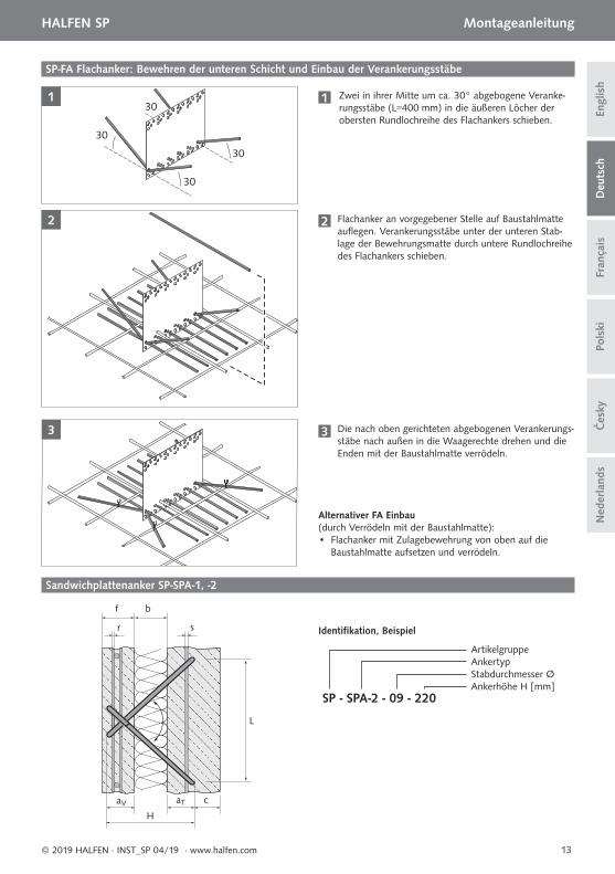
SP-FA Flachanker: Bewehren der unteren Schicht und Einbau der Verankerungsstäbe
1 Zwei in ihrer Mitte um ca. 30° abgebogene Veranke-rungsstäbe (L=400 mm) in die äußeren Löcher der obersten Rundlochreihe des Flachankers schieben.
2 Flachanker an vorgegebener Stelle auf Baustahlmatte aufl egen. Verankerungsstäbe unter der unteren Stab-lage der Bewehrungsmatte durch untere Rundlochreihe des Flachankers schieben.
3 Die nach oben gerichteten abgebogenen Verankerungs-stäbe nach außen in die Waagerechte drehen und die Enden mit der Baustahlmatte verrödeln.
Alternativer FA Einbau(durch Verrödeln mit der Baustahlmatte):• Flachanker mit Zulagebewehrung von oben auf die
Baustahlmatte aufsetzen und verrödeln.
Sandwichplattenanker SP-SPA-1, -2
SP - SPA-2 - 09 - 220
ArtikelgruppeAnkertyp Stabdurchmesser ØAnkerhöhe H [mm]
Identifi kation, Beispiel
b
s
aV aT c
H
r
f
L
14
HALFEN SP Montageanleitung D
euts
chEn
glis
hFr
ança
isPo
lski
© 2019 HALFEN · INST_SP 04/19 · www.halfen.com
Čes
kyN
eder
land
s
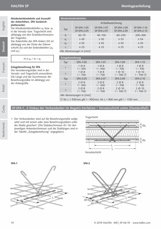
Mindesteinbindetiefe und Auswahl der Ankerhöhen, SPA Sandwich- plattenankerDie Mindesteinbindetiefen aV bzw. aT in die Vorsatz- bzw. Tragschicht sind abhängig von den Drahtdurchmessern der Traganker.Die Ankerhöhe des SPA Ankers (H) ist abhängig von der Dicke der Dämm-schicht (b) und der Einbindetiefen (aV und aT).
Zulagebewehrung für SPADie Verankerungsstäbe sind in der Vorsatz- und Tragschicht anzuordnen. Die Länge und der Durchmesser der Bewehrungsstäbe ist abhängig von der Ankergröße.
SP-SPA-1, -2 Einbau der Verbundanker im Negativ-Verfahren = Vorsatzschicht unten (Standardfall)
• Der Verbundanker wird auf die Bewehrungsmatte aufge-setzt und mit einem oder zwei Bewehrungsstäben unter der Matte gesichert. (Die Stabdurchmesser Ø r für den jeweiligen Ankerdurchmesser und die Stablängen sind in der Tabelle „Zulagebewehrung“ angegeben).
Mindesteinbindetiefen
Artikelbezeichnung
TypSP-SPA-1-05 SP-SPA-2-05
SP-SPA-1-07 SP-SPA-2-07
SP-SPA-1-09SP-SPA-2-09
SP-SPA-1-10SP-SPA-2-10
b 30–70 40–150 60–250 200–300
av ≥ 49 ≥ 50 ≥ 53 ≥ 54
aT ≥ 55 ≥ 55 ≥ 55 ≥ 55
c ≥ 25 ≥ 25 ≥ 25 ≥ 25
Alle Abmessungen in [mm]
Zulagebewehrung
Typ SPA-1-05 SPA-1-07 SPA-1-09 SPA-1-10
r 1 Ø 8 1 Ø 8 1 Ø 8 1 Ø 8l = 450 l = 450 l = 700 l = 700
s 1 Ø 8 1 Ø 8 1 Ø 10 1 Ø 10l = 700 l = 700 l = 700 l = 700
Typ SPA-2-05 SPA-2-07 SPA-2-09 SPA-2-10
r 2 Ø 8 2 Ø 8 2 Ø 8 2 Ø 8l = 450 l = 450 l = 700 l = 700
s 2 Ø 8 2 Ø 8 2 Ø 10 2 Ø 10l = 700 l = 700 l = 700 l = 700
Alle Abmessungen in [mm]
für L > 500 mm gilt l = 900 mm, für L > 800 mm gilt l = 1100 mm.
H ≥ aV + b + aT
lr
Ør
SPA-1
lrØrØr
SPA-2
Øs
Ør
Tragschicht
Vorsatzschichtlslr
Vor
satz
schi
cht
Trag
schi
cht
f ≥ 60 b ≥ 100
≥ 5≥ 30 * ≥ 30 * ≥ 55
av
aT
Vor
satz
schi
cht
Trag
schi
cht
f ≥ 60 b ≥ 100
≥ 50≥ 5 ≥ 55 ≥ 50av aT
Vor
satz
schi
cht
Trag
schi
cht
f ≥ 60 b ≥ 100
≥ 35≥ 30 * ≥ 30 * ≥ 65
av
aT
15
HALFEN SP Montageanleitung
Deu
tsch
Engl
ish
Pols
kiFr
ança
is
© 2019 HALFEN · INST_SP 04/19 · www.halfen.com
Čes
kyN
eder
land
s
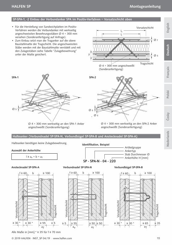
SP-SPA-1, -2 Einbau der Verbundanker SPA im Positiv-Verfahren = Vorsatzschicht oben
• Für die Herstellung von Sandwichplatten im Positiv-Verfahren werden die Verbundanker mit werkseitig angeschweissten Bewehrungsstäben Ø 4 × 300 mm versehen (Sonderanfertigung auf Anfrage).
• Zum Einbau setzt man die Traganker auf die obere Baustahlmatte der Tragschicht. Die angeschweissten Stäbe werden mit der Baustahlmatte verrödelt und mit den Zulagestäben siehe Tabelle “Zulagebewehrung” unter der Matte gesichert.
Ø s Ø s
Ø s
Ø 4 × 300 mm angeschweißt (Sonderanfertigung)
Vorsatzschicht
Tragschicht
lrls
Ø r
Ø sy
Ø 4 × 300 mm werkseitig an den SPA-1 Anker angeschweißt (Sonderanfertigung)
Ø 4 × 300 mm werkseitig an den SPA-2 Anker angeschweißt (Sonderanfertigung)
SPA-1 SPA-2
ls ls
Halteanker benötigen keine Zulagebewehrung.
Halteanker (Verbundnadel SP-SPA-N, Verbundbügel SP-SPA-B und Anstecknadel SP-SPA-A)
Auswahl der Ankerhöhe
l ≥ av + b + aT
SP - SPA-N - 04 - 220
ArtikelgruppeAnkertypStab Durchmesser ØAnkerhöhe H [mm]
Identifi kation, Beispiel
Anstecknadel SP-SPA-A Verbundnadel SP-SPA-N Verbundbügel SP-SPA-B
Alle Maße in [mm].* ≥ 35 für f ≥ 70 mm
16
HALFEN SP Montageanleitung D
euts
chEn
glis
hFr
ança
isPo
lski
© 2019 HALFEN · INST_SP 04/19 · www.halfen.com
Čes
kyN
eder
land
s
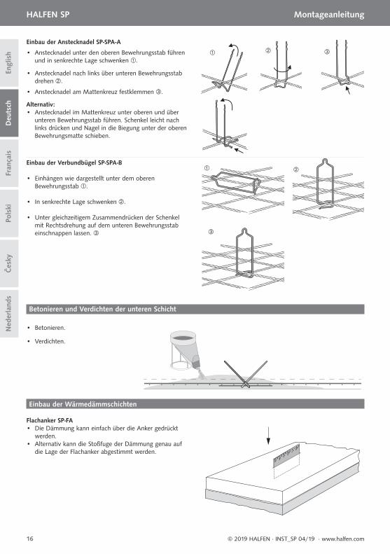
Einbau der Anstecknadel SP-SPA-A
Einbau der Verbundbügel SP-SPA-B
• Anstecknadel unter den oberen Bewehrungsstab führen und in senkrechte Lage schwenken .
• Anstecknadel nach links über unteren Bewehrungsstab drehen .
• Anstecknadel am Mattenkreuz festklemmen .
Alternativ: • Anstecknadel im Mattenkreuz unter oberen und über unteren Bewehrungsstab führen. Schenkel leicht nach links drücken und Nagel in die Biegung unter der oberen Bewehrungsmatte schieben.
• Einhängen wie dargestellt unter dem oberen Bewehrungsstab .
• In senkrechte Lage schwenken .
• Unter gleichzeitigem Zusammendrücken der Schenkel mit Rechtsdrehung auf dem unteren Bewehrungsstab einschnappen lassen.
• Betonieren.
• Verdichten.
Betonieren und Verdichten der unteren Schicht
Einbau der Wärmedämmschichten
Flachanker SP-FA • Die Dämmung kann einfach über die Anker gedrückt werden.• Alternativ kann die Stoßfuge der Dämmung genau auf die Lage der Flachanker abgestimmt werden.
17
HALFEN SP Montageanleitung
Deu
tsch
Engl
ish
Pols
kiFr
ança
is
© 2019 HALFEN · INST_SP 04/19 · www.halfen.com
Čes
kyN
eder
land
s
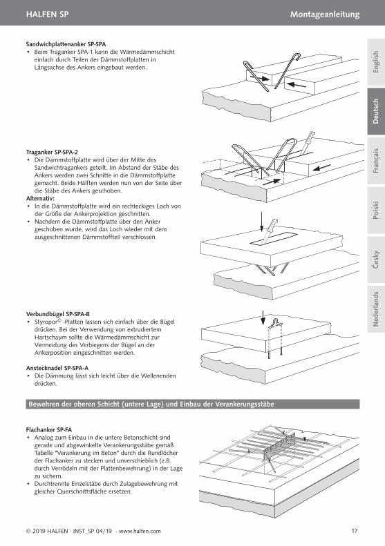
Sandwichplattenanker SP-SPA • Beim Traganker SPA-1 kann die Wärmedämmschicht einfach durch Teilen der Dämmstoff platten in Längsachse des Ankers eingebaut werden.
Traganker SP-SPA-2 • Die Dämmstoff platte wird über der Mitte des Sandwichtragankers geteilt. Im Abstand der Stäbe des Ankers werden zwei Schnitte in die Dämmstoff platte gemacht. Beide Hälften werden nun von der Seite über die Stäbe des Ankers geschoben.Alternativ: • In die Dämmstoff platte wird ein rechteckiges Loch von der Größe der Ankerprojektion geschnitten.• Nachdem die Dämmstoff platte über den Anker geschoben wurde, wird das Loch wieder mit dem ausgeschnittenen Dämmstoff teil verschlossen.
Verbundbügel SP-SPA-B• Styropor© -Platten lassen sich einfach über die Bügel drücken. Bei der Verwendung von extrudiertem Hartschaum sollte die Wärmedämmschicht zur Vermeidung des Verbiegens der Bügel an der Ankerposition eingeschnitten werden.
Flachanker SP-FA• Analog zum Einbau in die untere Betonschicht sind gerade und abgewinkelte Verankerungsstäbe gemäß Tabelle "Verankerung im Beton" durch die Rundlöcher der Flachanker zu stecken und unverschieblich (z.B. durch Verrödeln mit der Plattenbewehrung) in der Lage zu sichern.• Durchtrennte Einzelstäbe durch Zulagebewehrung mit gleicher Querschnittsfl äche ersetzen.
Anstecknadel SP-SPA-A• Die Dämmung lässt sich leicht über die Wellenenden drücken.
Bewehren der oberen Schicht (untere Lage) und Einbau der Verankerungsstäbe
18
HALFEN SP Montageanleitung D
euts
chEn
glis
hFr
ança
isPo
lski
© 2019 HALFEN · INST_SP 04/19 · www.halfen.com
Čes
kyN
eder
land
s
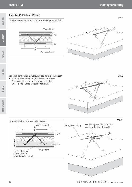
Positiv-Verfahren = Vorsatzschicht oben
Zulagebewehrung Bewehrungsstab der Baustahl-matte in der Vorsatzschicht
• Ein bzw. zwei Bewehrungsstäbe durch die SPA- Schlaufenenden durchstecken und befestigen. Øs, ls, siehe Tabelle "Zulagebewehrung".
lsØs
Ør
Verlegen der unteren Bewehrungslage für die Tragschicht
SPA-1
SPA-2
Ø 4 × 300 mm angeschweißt (Sonderanfertigung)
Vorsatzschicht
Tragschicht
lrls
Ø r
Ø s
y
lsØs
SPA-1Negativ-Verfahren = Vorsatzschicht unten (Standardfall)
Tragschicht
Vorsatzschicht
lrls
Øs
Ør
Traganker SP-SPA-1 und SP-SPA-2
19
HALFEN SP Montageanleitung
Deu
tsch
Engl
ish
Pols
kiFr
ança
is
© 2019 HALFEN · INST_SP 04/19 · www.halfen.com
Čes
kyN
eder
land
s
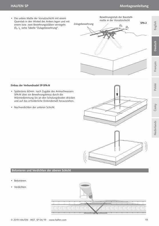
Zulagebewehrung
Bewehrungsstab der Baustahl-matte in der Vorsatzschicht
• Die untere Matte der Vorsatzschicht mit einem Querstab in den Winkel des Ankers legen und mit einem bzw. zwei Bewehrungsstäben verriegeln. Ør, lr, siehe Tabelle "Zulagebewehrung".
Ør Ør
SPA-2
• Spätestens 60min. nach Zugabe des Anmachwassers SPA-N über ein Bewehrungskreuz durch die Wärmedämmung bis an den Schalungsboden drücken und auf das erforderliche Einbindemaß herausziehen.
Einbau der Verbundnadel SP-SPA-N
• Nachverdichten der unteren Schicht.
• Betonieren.
• Verdichten.
Betonieren und Verdichten der oberen Schicht
20
HALFEN SP Notice d‘utilisation D
euts
chEn
glis
hFr
ança
isPo
lski
© 2019 HALFEN · INST_SP 04/19 · www.halfen.com
Čes
kyN
eder
land
s
Aperçu du produit / matériau
Épingle de liaison type SP-SPA-N
Épingle à clipser type SP-SPA-A
Étrier de liaison type SP-SPA-B
Plat de liaison type SP-FA
Liaison pour pan-neaux sandwich type SP-SPA-2
Liaison pour pan-neaux sandwich type SP-SPA-1
Assemblage de panneaux sandwich – remarques générales
Concept et calcul
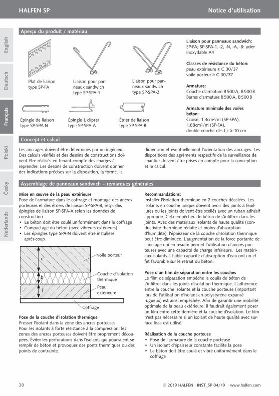
Mise en œuvre de la peau extérieure Pose de l'armature dans le coff rage et montage des ancres porteuses et des étriers de liaison SP-SPA-B, resp. des épingles de liaison SP-SPA-A selon les données deconstruction• Le béton doit être coulé uniformément dans le coff rage• Compactage du béton (avec vibreurs extérieurs)• Les épingles type SPA-N doivent être installées
après-coup.
Liaison pour panneaux sandwich: SP-FA; SP-SPA-1, -2, -N, -A, -B: acier inoxydable A4
Classes de résistance du béton:peau extérieure ≥ C 30/37voile porteur ≥ C 30/37
Armature:Couche d'armature B 500 A, B 500 BBarres d'armature B 500 A, B 500 B
Armature minimale des voilesbéton:Croisé, 1,3cm²/m (SP-SPA), 1,88cm²/m (SP-FA), double couche dès f,c ≥ 10 cm
voile porteur
Couche d'isolation thermique
Coff rage
Peauextérieure
c
b
f
Les ancrages doivent être déterminés par un ingénieur. Des calculs vérifi és et des dessins de constructions doi-vent être réalisés en tenant compte des charges à reprendre. Les dessins de construction doivent donner des indications précises sur la disposition, la forme, la
dimension et éventuellement l'orientation des ancrages. Les dispositions des agréments respectifs de la surveillance de chantier doivent être prises en compte pour la conception et le calcul.
Pose de la couche d'isolation thermiquePresser l'isolant dans la zone des ancres porteuses.Pour les isolants à forte résistance à la compression, les zones des ancres porteuses doivent être proprement décou-pées. Éviter les perforations dans l'isolant, qui pourraient se remplir de béton et provoquer des ponts thermiques ou des points de contrainte.
Recommandations:Installer l'isolation thermique en 2 couches décalées. Les isolants en couche unique doivent avoir des joints à feuil-lures ou les joints doivent être scellés avec un ruban adhésif approprié. Cela empêchera le béton de s'infi ltrer dans les joints. Avec des matériaux isolants de haute qualité (con-ductivité thermique réduite et moins d'absorption d'humidité), l'épaisseur de la couche d'isolation thermique peut être diminuée. L’augmentation de la force portante de l’ancrage qui en résulte permet l’utilisation d’ancres por-teuses avec une capacité de charge inférieure. Les matéri-aux isolants à faible capacité d'absorption d'eau ont un ef-fet favorable sur le retrait du béton.
Pose d'un fi lm de séparation entre les couchesLe fi lm de séparation empêche le coulis de béton de s'infi ltrer dans les joints d'isolation thermique. L'adhérence entre la couche isolante et la couche porteuse (important lors de l'utilisation d'isolant en polystyrène expansé rugueux) est ainsi empêchée. Afi n de garantir une mobilité optimale de la peau extérieure, il faudrait également poser un fi lm entre cette dernière et la couche d'isolation. Le fi lm n'est pas nécessaire si un isolant de haute qualité avec sur-face lisse est utilisé.
Réalisation de la couche porteuse• Pose de l'armature de la couche porteuse• Un isolant d'épaisseur constante facilite la pose• Le béton doit être coulé et vibré uniformément dans le
coff rage
21
HALFEN SP Notice d‘utilisation
Deu
tsch
Engl
ish
Pols
kiFr
ança
is
© 2019 HALFEN · INST_SP 04/19 · www.halfen.com
Čes
kyN
eder
land
s
Lors du décoff rage de panneaux sandwich, l'adhérence doit être aussi faible que possible. Il faut en particulier éviter de lever parallèlement à la table basculante!
Important: Lors de l'utilisation d'un vibreur, évitez tout contact entre ce dernier et les ancres. Le contact provoquerait une séparation du voile porteur, ent-rainant des variations de couleur et rendant le contour des ancrages visible.
Plat de liaison SP-FA
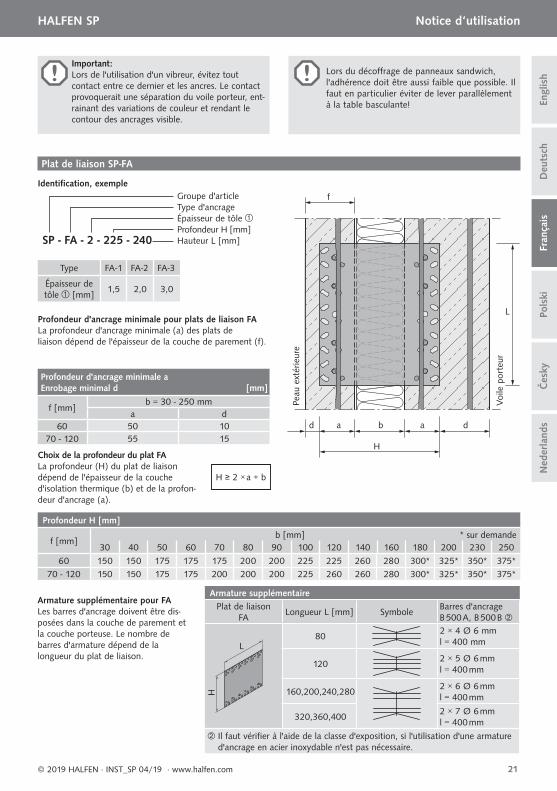
Profondeur d'ancrage minimale pour plats de liaison FA La profondeur d'ancrage minimale (a) des plats de liaison dépend de l'épaisseur de la couche de parement (f).
Type FA-1 FA-2 FA-3
Épaisseur de tôle [mm]
1,5 2,0 3,0
SP - FA - 2 - 225 - 240
Groupe d'articleType d'ancrageÉpaisseur de tôleProfondeur H [mm]Hauteur L [mm]
Identifi cation, exemple
d a a d
L
f
b
H
Voi
le p
orte
ur
Peau
ext
érie
ure
H ≥ 2 × a + b
Choix de la profondeur du plat FALa profondeur (H) du plat de liaison dépend de l'épaisseur de la couche d'isolation thermique (b) et de la profon-deur d'ancrage (a).
Profondeur d'ancrage minimale a Enrobage minimal d [mm]
f [mm]b = 30 - 250 mm
a d60 50 10
70 - 120 55 15
Profondeur H [mm]
f [mm]b [mm] * sur demande
30 40 50 60 70 80 90 100 120 140 160 180 200 230 250
60 150 150 175 175 175 200 200 225 225 260 280 300* 325* 350* 375*70 - 120 150 150 175 175 200 200 200 225 260 260 280 300* 325* 350* 375*
Armature supplémentaire pour FALes barres d'ancrage doivent être dis-posées dans la couche de parement et la couche porteuse. Le nombre de barres d'armature dépend de la longueur du plat de liaison.
Armature supplémentairePlat de liaison
FALongueur L [mm] Symbole
Barres d'ancrageB 500 A, B 500 B
L
H
802 × 4 Ø 6 mml = 400 mm
1202 × 5 Ø 6 mml = 400 mm
160,200,240,2802 × 6 Ø 6 mml = 400 mm
320,360,4002 × 7 Ø 6 mml = 400 mm
Il faut vérifi er à l'aide de la classe d'exposition, si l'utilisation d'une armature d'ancrage en acier inoxydable n'est pas nécessaire.
b
sr
f
L
aV aT c
H
30
30
30
30 1
2
3
22
HALFEN SP Notice d‘utilisation D
euts
chEn
glis
hFr
ança
isPo
lski
© 2019 HALFEN · INST_SP 04/19 · www.halfen.com
Čes
kyN
eder
land
s
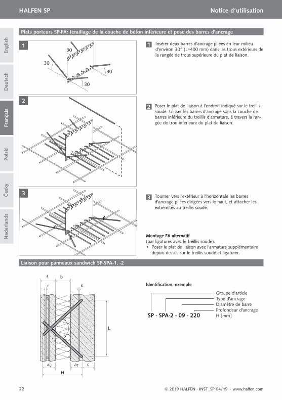
Plats porteurs SP-FA: féraillage de la couche de béton inférieure et pose des barres d'ancrage
1 Insérer deux barres d'ancrage pliées en leur milieu d'environ 30° (L=400 mm) dans les trous extérieurs de la rangée de trous supérieure du plat de liaison.
2 Poser le plat de liaison à l'endroit indiqué sur le treillis soudé. Glisser les barres d'ancrage sous la couche de barres inférieure du treillis d'armature, à travers la ran-gée de trou inférieure du plat de liaison.
3 Tourner vers l'extérieur à l'horizontale les barres d'ancrage pliées dirigées vers le haut, et attacher les extrémités au treillis soudé.
Montage FA alternatif (par ligatures avec le treillis soudé):• Poser le plat de liaison avec l'armature supplémentaire
depuis dessus sur le treillis soudé et ligaturer.
Liaison pour panneaux sandwich SP-SPA-1, -2
SP - SPA-2 - 09 - 220
Groupe d'articleType d'ancrage Diamètre de barreProfondeur d'ancrage H [mm]
Identifi cation, exemple
Voile porteur
Peau extérieure
Øs
Ør
lslr
23
HALFEN SP Notice d‘utilisation
Deu
tsch
Engl
ish
Pols
kiFr
ança
is
© 2019 HALFEN · INST_SP 04/19 · www.halfen.com
Čes
kyN
eder
land
s
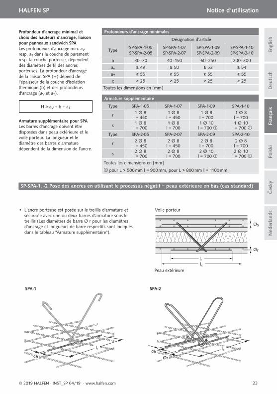
Profondeurs d'ancrage minimales
Désignation d’article
TypeSP-SPA-1-05 SP-SPA-2-05
SP-SPA-1-07 SP-SPA-2-07
SP-SPA-1-09SP-SPA-2-09
SP-SPA-1-10SP-SPA-2-10
b 30–70 40–150 60–250 200–300
av ≥ 49 ≥ 50 ≥ 53 ≥ 54
aT ≥ 55 ≥ 55 ≥ 55 ≥ 55
c ≥ 25 ≥ 25 ≥ 25 ≥ 25
Toutes les dimensions en [mm]
Armature supplémentaire
Type SPA-1-05 SPA-1-07 SPA-1-09 SPA-1-10
r 1 Ø 8 1 Ø 8 1 Ø 8 1 Ø 8l = 450 l = 450 l = 700 l = 700
s 1 Ø 8 1 Ø 8 1 Ø 10 1 Ø 10l = 700 l = 700 l = 700 l = 700
Type SPA-2-05 SPA-2-07 SPA-2-09 SPA-2-10
r 2 Ø 8 2 Ø 8 2 Ø 8 2 Ø 8l = 450 l = 450 l = 700 l = 700
s 2 Ø 8 2 Ø 8 2 Ø 10 2 Ø 10l = 700 l = 700 l = 700 l = 700
Toutes les dimensions en [mm]
pour L > 500 mm l = 900 mm, pour L > 800 mm l = 1100 mm.
Profondeur d'ancrage minimal et choix des hauteurs d'ancrage, liaison pour panneaux sandwich SPALes profondeurs d'ancrage min. aV resp. aT dans la couche de parement resp. la couche porteuse, dépendent des diamètres de fi l des ancres porteuses. La profondeur d'ancrage de la liaison SPA (H) dépend de l'épaisseur de la couche d'isolation thermique (b) et des profondeurs d'ancrage (aV et aT).
H ≥ aV + b + aT
Armature supplémentaire pour SPALes barres d'ancrage doivent être disposées dans peau extérieure et le voile porteur. La longueur et le diamètre des barres d'armature dépendent de la dimension de l'ancre.
SP-SPA-1, -2 Pose des ancres en utilisant le processus négatif = peau extérieure en bas (cas standard)
• L'ancre porteuse est posée sur le treillis d'armature et sécurisée avec une ou deux barres d'armature sous le treillis (Les diamètres de barre Ø r pour les diamètres d'ancrage et longueurs de barre respectifs sont indiqués dans le tableau "Armature supplémentaire").
lr
Ør
SPA-1
lrØrØr
SPA-2
Peau
ext
érie
ur
Voi
le p
orte
ur
f ≥ 60 b ≥ 100
≥ 5≥ 30 * ≥ 30 * ≥ 55
av
aT
Peau
ext
érie
ur
Voi
le p
orte
ur
f ≥ 60 b ≥ 100
≥ 50≥ 5 ≥ 55 ≥ 50av aT
Peau
ext
érie
ur
Voi
le p
orte
ur
f ≥ 60 b ≥ 100
≥ 35≥ 30 * ≥ 30 * ≥ 65
av
aT
24
HALFEN SP Notice d‘utilisation D
euts
chEn
glis
hFr
ança
isPo
lski
© 2019 HALFEN · INST_SP 04/19 · www.halfen.com
Čes
kyN
eder
land
s
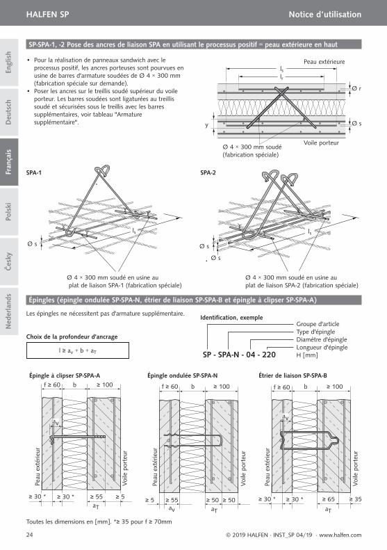
SP-SPA-1, -2 Pose des ancres de liaison SPA en utilisant le processus positif = peau extérieure en haut
• Pour la réalisation de panneaux sandwich avec le processus positif, les ancres porteuses sont pourvues en usine de barres d'armature soudées de Ø 4 × 300 mm (fabrication spéciale sur demande).
• Poser les ancres sur le treillis soudé supérieur du voile porteur. Les barres soudées sont ligaturées au treillis soudé et sécurisées sous le treillis avec les barres supplémentaires, voir tableau "Armature supplémentaire".
Ø 4 × 300 mm soudé (fabrication spéciale)
Peau extérieure
Voile porteur
lrls
Ø r
Ø sy
Ø 4 × 300 mm soudé en usine au plat de liaison SPA-1 (fabrication spéciale)
Ø 4 × 300 mm soudé en usine au plat de liaison SPA-2 (fabrication spéciale)
Ø s Ø s
Ø s
SPA-1 SPA-2
ls ls
Épingles (épingle ondulée SP-SPA-N, étrier de liaison SP-SPA-B et épingle à clipser SP-SPA-A)
Les épingles ne nécessitent pas d'armature supplémentaire.
Choix de la profondeur d'ancrage
l ≥ av + b + aT SP - SPA-N - 04 - 220
Groupe d'articleType d'épingleDiamètre d'épingleLongueur d'épingleH [mm]
Identifi cation, exemple
Épingle à clipser SP-SPA-A
Toutes les dimensions en [mm]. *≥ 35 pour f ≥ 70mm
Épingle ondulée SP-SPA-N Étrier de liaison SP-SPA-B
25
HALFEN SP Notice d‘utilisation
Deu
tsch
Engl
ish
Pols
kiFr
ança
is
© 2019 HALFEN · INST_SP 04/19 · www.halfen.com
Čes
kyN
eder
land
s
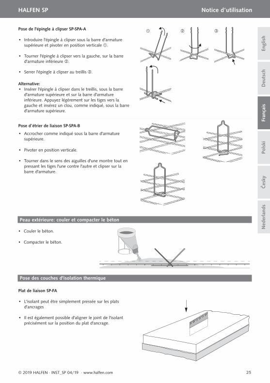
Pose de l'épingle à clipser SP-SPA-A
Pose dʼétrier de liaison SP-SPA-B
• Introduire l'épingle à clipser sous la barre d'armature supérieure et pivoter en position verticale .
• Tourner l'épingle à clipser vers la gauche, sur la barre d'armature inférieure .
• Serrer l'épingle à clipser au treillis .
Alternative: • Insérer l'épingle à clipser dans le treillis, sous la barre d'armature supérieure et sur la barre d'armature inférieure. Appuyez légèrement sur les tiges vers la gauche et insérez un clou, comme indiqué, sous la barre d'armature supérieure.
• Accrocher comme indiqué sous la barre d'armature supérieure.
• Pivoter en position verticale.
• Tourner dans le sens des aiguilles d'une montre tout en pressant les tiges l'une contre l'autre et clipser sur la barre d'armature.
• L'isolant peut être simplement pressée sur les plats d'ancrages
• Il est également possible d'aligner le joint de l'isolant précisément sur la position du plat d'ancrage.
• Couler le béton.
• Compacter le béton.
Peau extérieure: couler et compacter le béton
Pose des couches d'isolation thermique
Plat de liaison SP-FA
26
HALFEN SP Notice d‘utilisation D
euts
chEn
glis
hFr
ança
isPo
lski
© 2019 HALFEN · INST_SP 04/19 · www.halfen.com
Čes
kyN
eder
land
s
Étrier de liaison SP-SPA-B• Les plaques de Styropor© se laissent simplement presser sur les étriers. En utilisant une mousse dure extrudée, la couche d'isolation thermique doit être incisée au droit de l'étrier afin d'éviter de le plier.
Épingle à clipser SP-SPA-A• L'isolation peut être pressée aisément sur les extrémités ondulées.
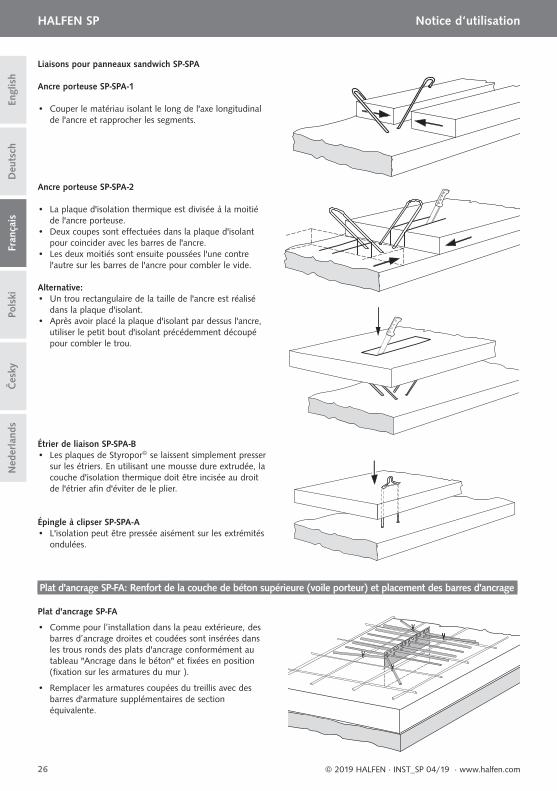
Liaisons pour panneaux sandwich SP-SPA
Ancre porteuse SP-SPA-1
• Couper le matériau isolant le long de l'axe longitudinal de l'ancre et rapprocher les segments.
Ancre porteuse SP-SPA-2
• La plaque d'isolation thermique est divisée à la moitié de l'ancre porteuse.• Deux coupes sont effectuées dans la plaque d'isolant pour coincider avec les barres de l'ancre.• Les deux moitiés sont ensuite poussées l'une contre l'autre sur les barres de l'ancre pour combler le vide.
Alternative: • Un trou rectangulaire de la taille de l'ancre est réalisé dans la plaque d'isolant.• Après avoir placé la plaque d'isolant par dessus l'ancre, utiliser le petit bout d'isolant précédemment découpé pour combler le trou.
Plat d'ancrage SP-FA: Renfort de la couche de béton supérieure (voile porteur) et placement des barres d'ancrage
Plat d'ancrage SP-FA
• Comme pour l’installation dans la peau extérieure, des barres d’ancrage droites et coudées sont insérées dans les trous ronds des plats d'ancrage conformément au tableau "Ancrage dans le béton" et fi xées en position (fi xation sur les armatures du mur ).
• Remplacer les armatures coupées du treillis avec des barres d'armature supplémentaires de section équivalente.
lsØs
Ør
lrls
Ø r
Ø s
y
lsØs
lrls
Øs
Ør
27
HALFEN SP Notice d‘utilisation
Deu
tsch
Engl
ish
Pols
kiFr
ança
is
© 2019 HALFEN · INST_SP 04/19 · www.halfen.com
Čes
kyN
eder
land
s
Armature supplémentaire
Barre d'armature du treillis soudé dans la peau extérieure
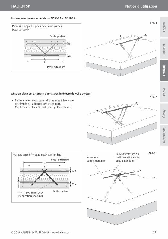
• Enfi ler une ou deux barres d'armatures à travers les extrémités de la boucle SPA et les fi xer. Øs, ls, voir tableau “Armatures supplémentaires“.
Mise en place de la couche d'armatures inférieure du voile porteur
Processus négatif = peau extérieure en bas (cas standard)
Voile porteur
Peau extérieure
Liaison pour panneaux sandwich SP-SPA-1 et SP-SPA-2
Processus positif = peau extérieure en haut
∅ 4 × 300 mm soudé (fabrication spéciale)
Voile porteur
Peau extérieure
SPA-1
SPA-2
SPA-1
28
HALFEN SP Notice d‘utilisation D
euts
chEn
glis
hFr
ança
isPo
lski
© 2019 HALFEN · INST_SP 04/19 · www.halfen.com
Čes
kyN
eder
land
s
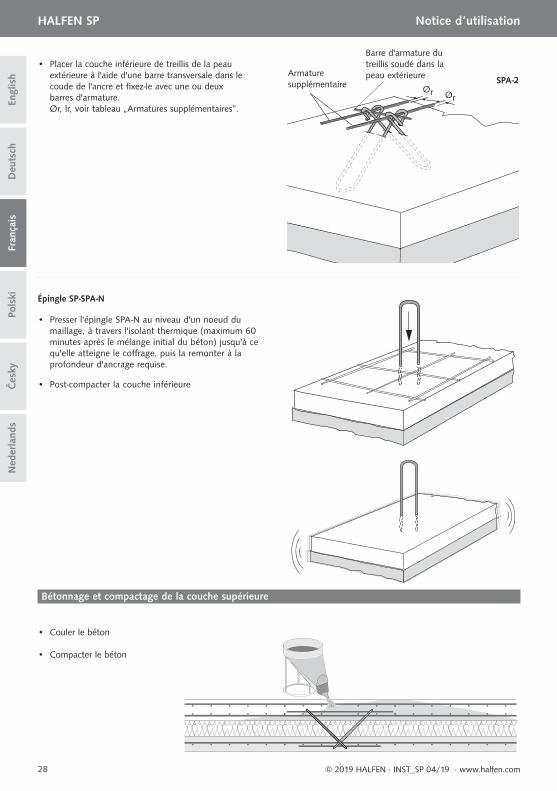
• Placer la couche inférieure de treillis de la peau extérieure à l'aide d'une barre transversale dans le coude de l'ancre et fi xez-le avec une ou deux barres d'armature. Ør, lr, voir tableau „Armatures supplémentaires”.
Ør Ør
SPA-2
• Presser l'épingle SPA-N au niveau d'un noeud du maillage, à travers l'isolant thermique (maximum 60 minutes après le mélange initial du béton) jusqu'à ce qu'elle atteigne le coff rage, puis la remonter à la profondeur d'ancrage requise.
Épingle SP-SPA-N
• Post-compacter la couche inférieure
• Couler le béton
• Compacter le béton
Bétonnage et compactage de la couche supérieure
Armature supplémentaire
Barre d'armature du treillis soudé dans la peau extérieure
29
HALFEN SP Instrukcja montażu
Deu
tsch
Engl
ish
Pols
kiFr
ança
is
© 2019 HALFEN · INST_SP 04/19 · www.halfen.com
Čes
kyN
eder
land
s
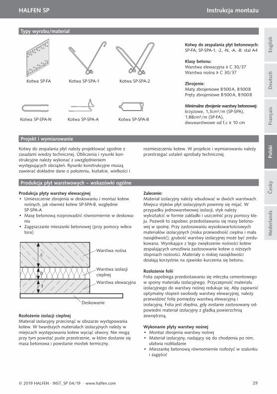
Typy wyrobu/materiał
Kotwa SP-SPA-N Kotwa SP-SPA-A Kotwa SP-SPA-B
Kotwa SP-FA Kotwa SP-SPA-2Kotwa SP-SPA-1
Produkcja płyt warstwowych – wskazówki ogólne
Projekt i wymiarowanie
Produkcja płyty warstwy elewacyjnej• Umieszczenie zbrojenia w deskowaniu i montaż kotew
nośnych, jak również kotew SP-SPA-B, względnie SP-SPA-A
• Masę betonową rozprowadzić równomiernie w deskowa-niu
• Zagęszczanie mieszanki betonowej (przy pomocy wibra-tora)
Kotwy do zespalania płyt betonowych: SP-FA; SP-SPA-1, -2, -N, -A, -B: stal A4
Klasy betonu:Warstwa elewacyjna ≥ C 30/37Warstwa nośna ≥ C 30/37
Zbrojenie:Maty zbrojeniowe B 500 A, B 500 BPręty zbrojeniowe B 500 A, B 500 B
Minimalne zbrojenie warstwy betonowej:krzyżowe, 1,3cm²/m (SP-SPA), 1,88cm²/m (SP-FA), dwuwarstwowe od f,c ≥ 10 cm
Warstwa nośna
Warstwa izolacji cieplnej
Deskowanie
Warstwa elewacyjna
c
b
f
Kotwy do zespalania płyt należy projektować zgodnie z zasadami wiedzy technicznej. Obliczenia i rysunki kon-strukcyjne należy wykonać z uwzględnieniem występujących obciążeń. Rysunki konstrukcyjne muszą zawierać dokładne dane o położeniu, kształcie, wielkości i
rozmieszczeniu kotew. W projekcie i wymiarowaniu należy przestrzegać ustaleń aprobaty technicznej.
Rozłożenie izolacji cieplnejMateriał izolacyjny przecisnąć w obszarze występowania kotew. W twardszych materiałach izolacyjnych należy w miejscach występowania kotew wyciąć otwory. Nie mogą przy tym powstać puste przestrzenie, w które dostanie się masa betonowa i powstanie mostek termiczny.
Zalecenie:Materiał izolacyjny należy wbudować w dwóch warstwach. Miejsca styków płyt izolacyjnych powinny się mijać. W przypadku jednowarstwowej izolacji, styk należy wykształcić w formie zakładki i uszczelnić przy pomocy kle-ju. Pozwoli to zapobiec przedostawaniu się masy betono-wej w spoinę. Przy zastosowaniu wysokowartościowych materiałów izolacyjnych (niska przewodność cieplna i mała nasiąkliwość), grubość warstwy izolacyjnej może być zredu-kowana. Wynikające z tego zwiększenie nośności kotew zespalających umożliwia zastosowanie kotew o niższych stopniach nośności. Materiały o niskiej nasiąkliwości działają korzystnie na zjawisko kurczenia się betonu.
Rozłożenie foliiFolia zapobiega przedostawaniu się mleczka cementowego w spoiny materiału izolacyjnego. Przyczepność materiału izolacyjnego do warstwy nośnej redukuje się. Aby zapewnić optymalny stopień swobody warstwy elewacyjnej, należy przewidzieć folię pomiędzy warstwą elewacyjną i izolacyjną. Folia jest zbędna, gdy zostanie zastosowany od-powiedni materiał izolacyjny z gładką powierzchnią zewnętrzną.
Wykonanie płyty warstwy nośnej• Montaż zbrojenia warstwy nośnej• Materiał izolacyjny, nadający się do chodzenia po nim,
ułatwia rozkładanie• Mieszankę betonową równomiernie rozłożyć w szalunku
i zagęścić
30
HALFEN SP Instrukcja montażu D
euts
chEn
glis
hFr
ança
isPo
lski
© 2019 HALFEN · INST_SP 04/19 · www.halfen.com
Čes
kyN
eder
land
s
Przy podnoszeniu prefabrykatów płyt zespolonych należy do minimum ograniczyć przyczepność. Nie podnosić równolegle do stołu roboczego!
Ważne: Przy stosowaniu wibratora należy unikać kontaktu buławy z kotwami, ponieważ może dojść do rozwarstwienia mieszanki betonowej warstwy elewacyjnej i w konsekwencji do zmian kolorubetonu oraz uwidocznienia konturu kotew.
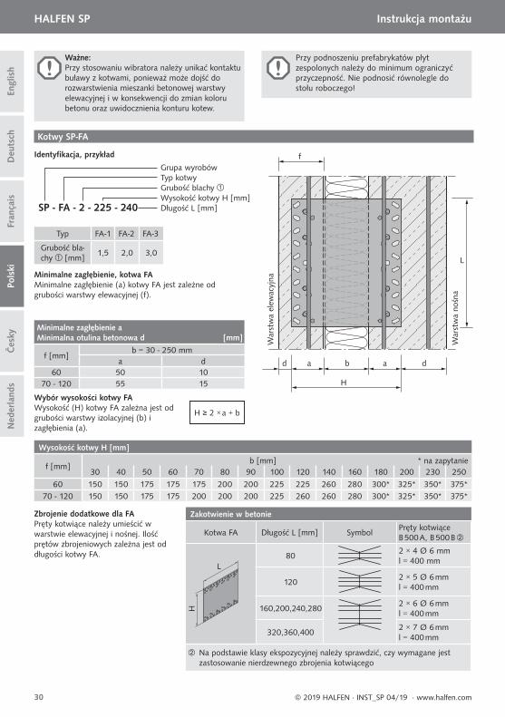
Kotwy SP-FA
Minimalne zagłębienie, kotwa FA Minimalne zagłębienie (a) kotwy FA jest zależne od grubości warstwy elewacyjnej (f).
Typ FA-1 FA-2 FA-3
Grubość bla-chy [mm]
1,5 2,0 3,0
H ≥ 2 × a + b
Wybór wysokości kotwy FAWysokość (H) kotwy FA zależna jest od grubości warstwy izolacyjnej (b) i zagłębienia (a).
SP - FA - 2 - 225 - 240
Grupa wyrobówTyp kotwyGrubość blachyWysokość kotwy H [mm]Długość L [mm]
Identyfi kacja, przykład
d a a d
L
f
b
H
War
stw
a no
śna
War
stw
a el
ewac
yjna
Minimalne zagłębienie a Minimalna otulina betonowa d [mm]
f [mm]b = 30 - 250 mm
a d60 50 10
70 - 120 55 15
Wysokość kotwy H [mm]
f [mm]b [mm] * na zapytanie
30 40 50 60 70 80 90 100 120 140 160 180 200 230 250
60 150 150 175 175 175 200 200 225 225 260 280 300* 325* 350* 375*70 - 120 150 150 175 175 200 200 200 225 260 260 280 300* 325* 350* 375*
Zbrojenie dodatkowe dla FAPręty kotwiące należy umieścić w warstwie elewacyjnej i nośnej. Ilość prętów zbrojeniowych zależna jest od długości kotwy FA.
Zakotwienie w betonie
Kotwa FA Długość L [mm] SymbolPręty kotwiące B 500 A, B 500 B
L
H
802 × 4 Ø 6 mml = 400 mm
1202 × 5 Ø 6 mml = 400 mm
160,200,240,2802 × 6 Ø 6 mml = 400 mm
320,360,4002 × 7 Ø 6 mml = 400 mm
Na podstawie klasy ekspozycyjnej należy sprawdzić, czy wymagane jest zastosowanie nierdzewnego zbrojenia kotwiącego
3
2
30
30
30
30 1
31
HALFEN SP Instrukcja montażu
Deu
tsch
Engl
ish
Pols
kiFr
ança
is
© 2019 HALFEN · INST_SP 04/19 · www.halfen.com
Čes
kyN
eder
land
s
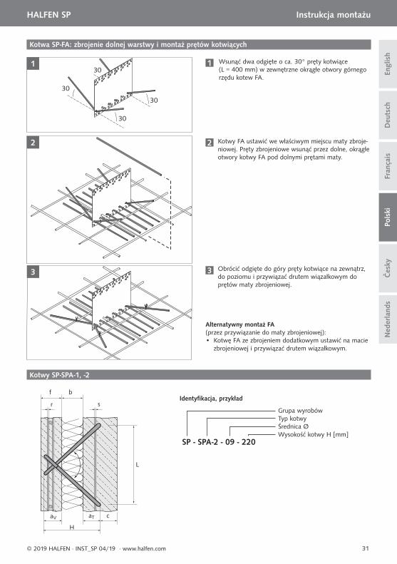
Kotwa SP-FA: zbrojenie dolnej warstwy i montaż prętów kotwiących
1 Wsunąć dwa odgięte o ca. 30° pręty kotwiące (L = 400 mm) w zewnętrzne okrągłe otwory górnego rzędu kotew FA.
2 Kotwy FA ustawić we właściwym miejscu maty zbroje-niowej. Pręty zbrojeniowe wsunąć przez dolne, okrągłe otwory kotwy FA pod dolnymi prętami maty.
3 Obrócić odgięte do góry pręty kotwiące na zewnątrz, do poziomu i przywiązać drutem wiązałkowym do prętów maty zbrojeniowej.
Alternatywny montaż FA (przez przywiązanie do maty zbrojeniowej):• Kotwę FA ze zbrojeniem dodatkowym ustawić na macie
zbrojeniowej i przywiązać drutem wiązałkowym.
Kotwy SP-SPA-1, -2
b
sr
f
L
SP - SPA-2 - 09 - 220
Grupa wyrobówTyp kotwy Średnica ØWysokość kotwy H [mm]
Identyfi kacja, przykład
aV aT c
H
lrlr
Ør
lrØrØr
Warstwa nośna
Warstwa elewacyjna
Øs
Ør
lslr
32
HALFEN SP Instrukcja montażu D
euts
chEn
glis
hFr
ança
isPo
lski
© 2019 HALFEN · INST_SP 04/19 · www.halfen.com
Čes
kyN
eder
land
s
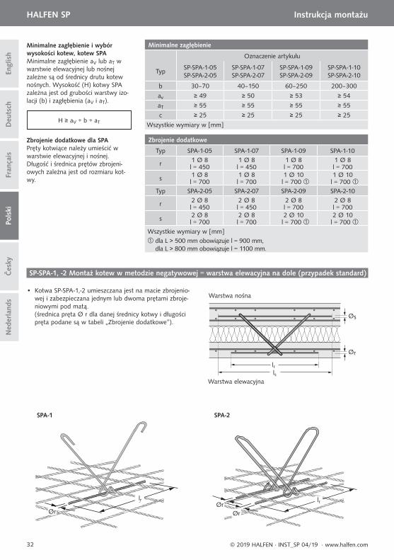
Minimalne zagłębienie i wybór wysokości kotew, kotew SPAMinimalne zagłębienie aV lub aT w warstwie elewacyjnej lub nośnej zależne są od średnicy drutu kotew nośnych. Wysokość (H) kotwy SPA zależna jest od grubości warstwy izo-lacji (b) i zagłębienia (aV i aT).
Zbrojenie dodatkowe dla SPAPręty kotwiące należy umieścić w warstwie elewacyjnej i nośnej. Długość i średnica prętów zbrojeni-owych zależna jest od rozmiaru kot-wy.
SP-SPA-1, -2 Montaż kotew w metodzie negatywowej = warstwa elewacyjna na dole (przypadek standard)
• Kotwa SP-SPA-1,-2 umieszczana jest na macie zbrojenio-wej i zabezpieczana jednym lub dwoma prętami zbroje-niowymi pod matą.(średnica pręta Ø r dla danej średnicy kotwy i długości pręta podane są w tabeli „Zbrojenie dodatkowe”).
Minimalne zagłębienie
Oznaczenie artykułu
TypSP-SPA-1-05 SP-SPA-2-05
SP-SPA-1-07 SP-SPA-2-07
SP-SPA-1-09SP-SPA-2-09
SP-SPA-1-10SP-SPA-2-10
b 30–70 40–150 60–250 200–300
av ≥ 49 ≥ 50 ≥ 53 ≥ 54
aT ≥ 55 ≥ 55 ≥ 55 ≥ 55
c ≥ 25 ≥ 25 ≥ 25 ≥ 25
Wszystkie wymiary w [mm]
Zbrojenie dodatkowe
Typ SPA-1-05 SPA-1-07 SPA-1-09 SPA-1-10
r 1 Ø 8 1 Ø 8 1 Ø 8 1 Ø 8l = 450 l = 450 l = 700 l = 700
s 1 Ø 8 1 Ø 8 1 Ø 10 1 Ø 10l = 700 l = 700 l = 700 l = 700
Typ SPA-2-05 SPA-2-07 SPA-2-09 SPA-2-10
r 2 Ø 8 2 Ø 8 2 Ø 8 2 Ø 8l = 450 l = 450 l = 700 l = 700
s 2 Ø 8 2 Ø 8 2 Ø 10 2 Ø 10l = 700 l = 700 l = 700 l = 700
Wszystkie wymiary w [mm] dla L > 500 mm obowiązuje l = 900 mm,
dla L > 800 mm obowiązuje l = 1100 mm.
H ≥ aV + b + aT
SPA-1 SPA-2
War
stw
a el
ewac
yjna
War
stw
a no
śna
f ≥ 60 b ≥ 100
≥ 5≥ 30 * ≥ 30 * ≥ 55
av
aT
War
stw
a el
ewac
yjna
War
stw
a no
śna
f ≥ 60 b ≥ 100
≥ 50≥ 5 ≥ 55 ≥ 50av aT
War
stw
a el
ewac
yjna
War
stw
a no
śna
f ≥ 60 b ≥ 100
≥ 35≥ 30 * ≥ 30 * ≥ 65
av
aT
33
HALFEN SP Instrukcja montażu
Deu
tsch
Engl
ish
Pols
kiFr
ança
is
© 2019 HALFEN · INST_SP 04/19 · www.halfen.com
Čes
kyN
eder
land
s
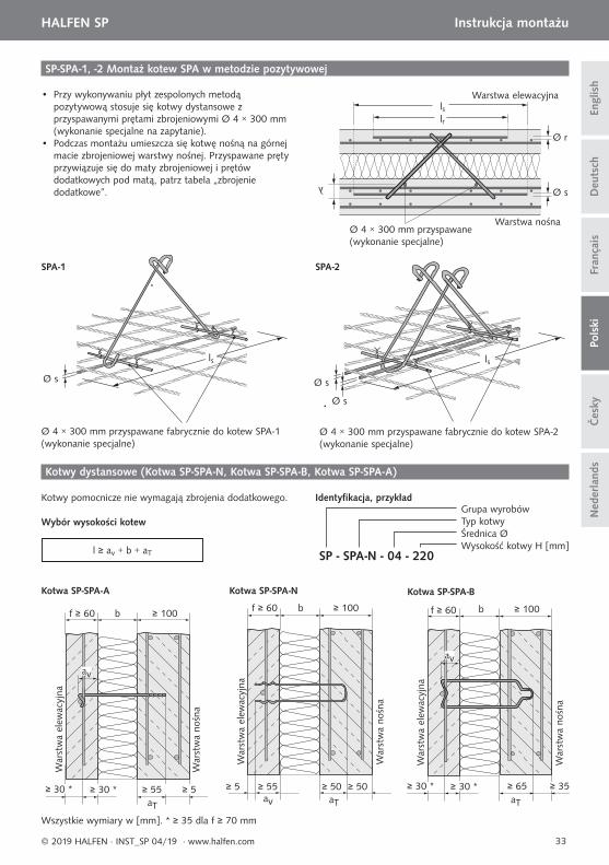
SP-SPA-1, -2 Montaż kotew SPA w metodzie pozytywowej
• Przy wykonywaniu płyt zespolonych metodą pozytywową stosuje się kotwy dystansowe z przyspawanymi prętami zbrojeniowymi Ø 4 × 300 mm (wykonanie specjalne na zapytanie).
• Podczas montażu umieszcza się kotwę nośną na górnej macie zbrojeniowej warstwy nośnej. Przyspawane pręty przywiązuje się do maty zbrojeniowej i prętów dodatkowych pod matą, patrz tabela „zbrojenie dodatkowe”.
Ø 4 × 300 mm przyspawane (wykonanie specjalne)
Warstwa elewacyjna
Warstwa nośna
lrls
Ø r
Ø sy
Ø 4 × 300 mm przyspawane fabrycznie do kotew SPA-1(wykonanie specjalne)
Ø 4 × 300 mm przyspawane fabrycznie do kotew SPA-2(wykonanie specjalne)
Ø s Ø s
Ø s
SPA-1 SPA-2
ls ls
Kotwy dystansowe (Kotwa SP-SPA-N, Kotwa SP-SPA-B, Kotwa SP-SPA-A)
Kotwy pomocnicze nie wymagają zbrojenia dodatkowego.
Wybór wysokości kotew
l ≥ av + b + aT SP - SPA-N - 04 - 220
Grupa wyrobówTyp kotwyŚrednica ØWysokość kotwy H [mm]
Identyfi kacja, przykład
Wszystkie wymiary w [mm]. * ≥ 35 dla f ≥ 70 mm
Kotwa SP-SPA-A Kotwa SP-SPA-N Kotwa SP-SPA-B
34
HALFEN SP Instrukcja montażu D
euts
chEn
glis
hFr
ança
isPo
lski
© 2019 HALFEN · INST_SP 04/19 · www.halfen.com
Čes
kyN
eder
land
s
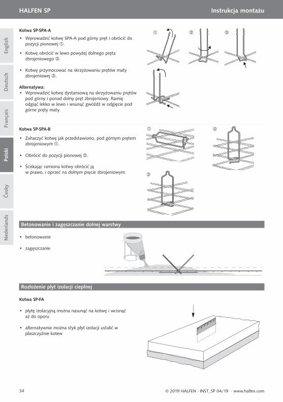
• Zahaczyć kotwę jak przedstawiono, pod górnym prętem zbrojeniowym .
• Obrócić do pozycji pionowej .
• Ściskając ramiona kotwy obrócić ją w prawo, i oprzeć na dolnym pręcie zbrojeniowym.
• Wprowadzić kotwę SPA-A pod górny pręt i obrócić do pozycji pionowej .
• Kotwę obrócić w lewo powyżej dolnego pręta zbrojeniowego .
• Kotwę przymocować na skrzyżowaniu prętów maty zbrojeniowej .
Alternatywa: • Wprowadzić kotwę dystansową na skrzyżowaniu prętów pod górny i ponad dolny pręt zbrojeniowy. Ramię odgiąć lekko w lewo i wsunąć gwóźdź w odgięcie pod górne pręty maty.
Kotwa SP-SPA-A
Kotwa SP-SPA-B
• betonowanie
• zagęszczanie
Betonowanie i zagęszczanie dolnej warstwy
Rozłożenie płyt izolacji cieplnej
Kotwa SP-FA
• płytę izolacyjną można nasunąć na kotwę i wcisnąć aż do oporu
• alternatywnie można styk płyt izolacji ustalić w płaszczyźnie kotew
35
HALFEN SP Instrukcja montażu
Deu
tsch
Engl
ish
Pols
kiFr
ança
is
© 2019 HALFEN · INST_SP 04/19 · www.halfen.com
Čes
kyN
eder
land
s
Kotwa SP-FA
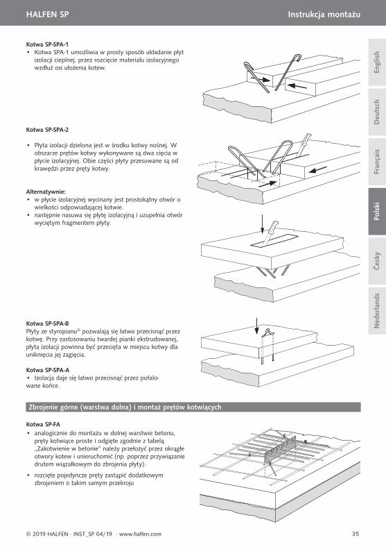
Kotwa SP-SPA-1• Kotwa SPA-1 umożliwia w prosty sposób układanie płyt izolacji cieplnej, przez rozcięcie materiału izolacyjnego wzdłuż osi ułożenia kotew.
Kotwa SP-SPA-2
• Płyta izolacji dzielona jest w środku kotwy nośnej. W obszarze prętów kotwy wykonywane są dwa cięcia w płycie izolacyjnej. Obie części płyty przesuwane są od krawędzi przez pręty kotwy.
Alternatywnie:• w płycie izolacyjnej wycinany jest prostokątny otwór o wielkości odpowiadającej kotwie.• następnie nasuwa się płytę izolacyjną i uzupełnia otwór wyciętym fragmentem płyty.
Kotwa SP-SPA-BPłyty ze styropianu© pozwalają się łatwo przecisnąć przez kotwę. Przy zastosowaniu twardej pianki ekstrudowanej, płyta izolacji powinna być przecięta w miejscu kotwy dla uniknięcia jej zagięcia.
Kotwa SP-SPA-A• Izolacja daje się łatwo przecisnąć przez pofalo-wane końce.
• analogicznie do montażu w dolnej warstwie betonu, pręty kotwiące proste i odgięte zgodnie z tabelą „Zakotwienie w betonie” należy przełożyć przez okrągłe otwory kotew i unieruchomić (np. poprzez przywiązanie drutem wiązałkowym do zbrojenia płyty).
Zbrojenie górne (warstwa dolna) i montaż prętów kotwiących
• rozcięte pojedyncze pręty zastąpić dodatkowym zbrojeniem o takim samym przekroju
36
HALFEN SP Instrukcja montażu D
euts
chEn
glis
hFr
ança
isPo
lski
© 2019 HALFEN · INST_SP 04/19 · www.halfen.com
Čes
kyN
eder
land
s
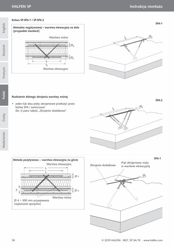
• jeden lub dwa pręty zbrojeniowe przełożyć przez kotwę SPA i zamocować. Øs, ls patrz tabela „Zbrojenie dodatkowe”.
lsØs
Ør
Rozłożenie dolnego zbrojenia warstwy nośnej
SPA-1
SPA-2
lrls
Ø r
Ø sy
lsØs
SPA-1
lrls
Øs
Ør
Zbrojenie dodatkowePręt zbrojeniowy maty w warstwie elewacyjnej
Ø 4 × 300 mm przyspawane (wykonanie specjalne)
Warstwa elewacyjna
Warstwa elewacyjna
Warstwa nośna
Warstwa nośna
Metoda pozytywowa – warstwa elewacyjna na górze
Metodzie negatywowej = warstwa elewacyjna na dole (przypadek standard)
Kotwa SP-SPA-1 i SP-SPA-2
37
HALFEN SP Instrukcja montażu
Deu
tsch
Engl
ish
Pols
kiFr
ança
is
© 2019 HALFEN · INST_SP 04/19 · www.halfen.com
Čes
kyN
eder
land
s
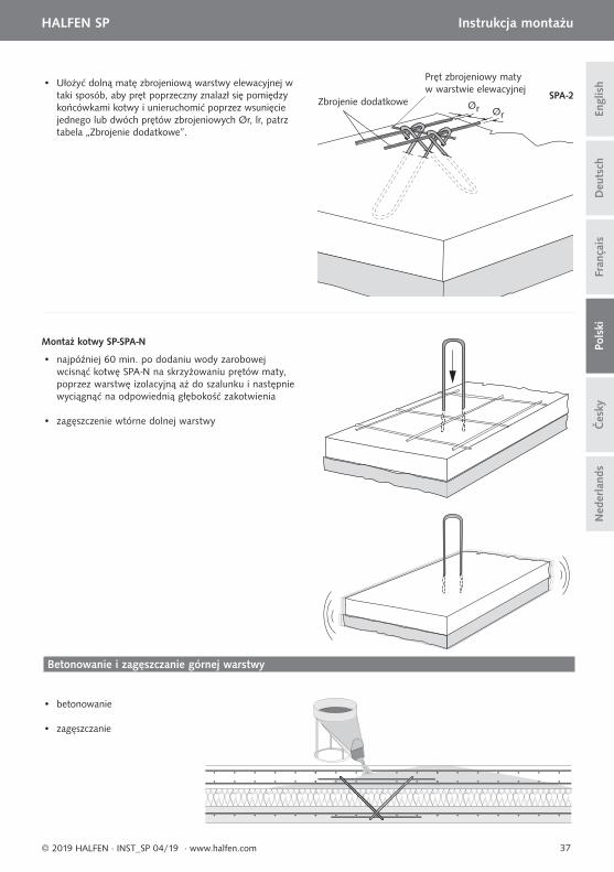
Zbrojenie dodatkowe
Pręt zbrojeniowy maty w warstwie elewacyjnej
• Ułożyć dolną matę zbrojeniową warstwy elewacyjnej w taki sposób, aby pręt poprzeczny znalazł się pomiędzy końcówkami kotwy i unieruchomić poprzez wsunięcie jednego lub dwóch prętów zbrojeniowych Ør, lr, patrz tabela „Zbrojenie dodatkowe”.
Ør Ør
SPA-2
• najpóźniej 60 min. po dodaniu wody zarobowej wcisnąć kotwę SPA-N na skrzyżowaniu prętów maty, poprzez warstwę izolacyjną aż do szalunku i następnie wyciągnąć na odpowiednią głębokość zakotwienia
• zagęszczenie wtórne dolnej warstwy
• betonowanie
• zagęszczanie
Betonowanie i zagęszczanie górnej warstwy
Montaż kotwy SP-SPA-N
38
HALFEN SP Montážní návod D
euts
chEn
glis
hFr
ança
isPo
lski
Čes
kyN
eder
land
s
© 2019 HALFEN · INST_SP 04/19 · www.halfen.com
Přehled výrobků / materiálů
Typ SP-SPA-N jednoduchá spona pro sendvičové panely
Typ SP-SPA-A podvlečená spona pro sendvičové panely
Typ SP-SPA-B třmínková spona pro sendvičové panely
Typ SP-FA plochá kotva
Typ SP-SPA-2 nosná kotva pro sendvičové panely
Typ SP-SPA-1 nosná kotva pro sendvičové panely
Výroba kotev – všeobecné informace
Návrh a dimenzování
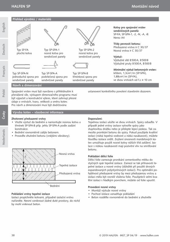
Zhotovení předsazené vrstvy• Vložte výztuž do bednění a namontujte nosnou kotvu a
třmínek SP-SPA-B příp. jehlu SP-SPA-A podle zadáníkonstrukce.
• Bednění rovnoměrně zalijte betonem.• Proveďte zhutnění betonu (vnějšími vibrátory).
Kotvy pro spojování vrstev sendvičových panelů:SP-FA; SP-SPA-1, -2, -N, -A, -B: Nerez A4
Třídy pevnosti betonu:Předsazená vrstva ≥ C 30/37Nosná vrstva ≥ C 30/37
Výztuž:Výztužné sítě B 500 A, B 500 BVýztužné pruty B 500 A, B 500 B
Minimální výztuž betonových vrstev:křížem, 1,3cm²/m (SP-SPA), 1,88cm²/m (SP-FA), ve dvou vrstvách od f,c ≥ 10 cm
Nosná vrstva
Tepelná izolace
Bednění
Předsazená vrstva
c
b
f
Spojování vrstev musí být navrženo s přihlédnutím k přenášené síle, výstupem dimenzačního programu musí být výpočet a konstrukční výkres, které zahrnují přesné údaje o vrstvách, tvaru, velikosti a směru kotev. Pro návrh a dimenzování musí být dodržována
ustanovení konkrétního povolení stavebním dozorem.
Pokládání vrstvy tepelné izolaceIzolaci propíchněte kotvami, případně izolační vrstvu nařízněte. Nesmí vzniknout žádné duté prostory, do nichž by mohl vniknout beton.
Doporučení:Tepelnou izolaci uložte ve dvou vrstvách. Spáry odsaďte. V případě jedné vrstvy izolace vytvořte spáry jako stupňovitou drážku nebo je přelepte lepicí páskou. Tak za-mezíte pronikání betonu do spáry. Pokud použijete kvalitní izolaci (nízká tepelná vodivost a nízká nasákavost), můžete tloušťku izolace snížit. Zvýšení únosnosti manžetových ko-tev umožňuje použít nosné kotvy nižších tříd zatížení. Izo-lace s nízkou nasákavostí mají pozivitní vliv na smršťování betonu.
Pokládání dělicí folieDělicí folie zamezuje pronikání cementového mléka do styčných spár tepelné izolace. Zamezí se tak přilnavosti te-pelné izolace a nosné vrstvy (důležité při použití drsných expandovaných polystyrénových izolací). Pro optimální po-hyblivost předsazené vrstvy by mezi předsazenou vrstvu a izolaci měla být rovněž vložena folie. Použijete-li velmi kva-litní izolaci s hladkým povrchem, můžete od folie upustit.
Provedení nosné vrstvy• Montáž výztuže nosné vrstvy• Pochozí izolace usnadňuje pokládání• Beton rozdělte rovnoměrně do bednění a zhutněte
39
HALFEN SP Montážní návod
Deu
tsch
Čes
kyEn
glis
hPo
lski
Fran
çais
Ned
erla
nds
© 2019 HALFEN · INST_SP 04/19 · www.halfen.com
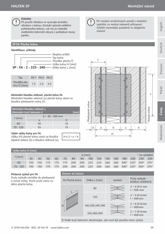
Při zvedání sendvičových panelů z bednění zajistěte co možná nejmenší přilnavost.Zvláště nezvedejte paralelně se sklápěcím stolem!
Důležité:Při použití vibrátoru se vyvarujte kontaktuvibrátoru s kotvou. Kontakt způsobí oddělenípohledového betonu, což má za následekzviditelnění kotevních obrysů z pohledové stranypanelu.
SP-FA Plochá kotva
Minimální hloubka vetknutí, plochá kotva FA Minimální hloubka vetknutí (a) ploché kotvy závisí na tloušťce předsazené vrstvy (f).
Typ FA-1 FA-2 FA-3
Tloušťka ple-chu [mm]
1,5 2,0 3,0
SP - FA - 2 - 225 - 240
Skupina artiklůTyp kotvyTloušťka plechuVýška kotvy H [mm]Délka kotvy L [mm]
Identifi kace, příklady
d a a d
L
f
b
H
Nos
ná v
rstv
a
Před
saze
ná v
rstv
a
H ≥ 2 × a + bVýběr výšky kotvy pro FAVýška (H) ploché kotvy závisí na tloušťce tepelné izolace (b) a hloubce vetknutí (a).
Minimální hloubka vetknutí a Minimální krytí betonem d [mm]
f [mm]b = 30 - 250 mm
a d60 50 10
70 - 120 55 15
Výška kotvy H [mm]
f [mm]b [mm] * na vyžádání
30 40 50 60 70 80 90 100 120 140 160 180 200 230 250
60 150 150 175 175 175 200 200 225 225 260 280 300* 325* 350* 375*70 - 120 150 150 175 175 200 200 200 225 260 260 280 300* 325* 350* 375*
Přídavná výztuž pro FAPruty výztuže umístěte do předsazené a nosné vrstvy. Počet prutů závisí na délce ploché kotvy.
Kotvení do betonu
FA Plochá kotva Délka L [mm] SymbolPruty výztužeB 500 A, B 500 B
L
H
802 × 4 Ø 6 mml = 400 mm
1202 × 5 Ø 6 mml = 400 mm
160,200,240,2802 × 6 Ø 6 mml = 400 mm
320,360,4002 × 7 Ø 6 mml = 400 mm
Podle krytí betonem zkontrolujte, zda musí být použita nerez výztuž.
3
2
30
30
30
30 1
40
HALFEN SP Montážní návod D
euts
chEn
glis
hFr
ança
isPo
lski
Čes
kyN
eder
land
s
© 2019 HALFEN · INST_SP 04/19 · www.halfen.com
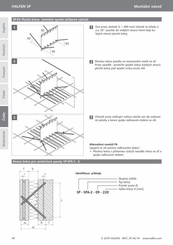
1 Dva pruty výztuže (L = 400 mm) ohnuté ve středu o cca 30° zasuňte do vnějších otvorů horní řady ku-latých otvorů ploché kotvy.
2 Plochou kotvu položte na stanoveném místě na síť. Pruty zaveďte - prostrčte spodní řadou kulatých otvorů ploché kotvy pod spodní vrstvu prutů sítě.
3 Ohnuté pruty směřující nahoru otočte ven do vodorov-né polohy a konce spojte rádlovacím drátem se sítí.
Alternativní montáž FA(spojení se sítí pomocí rádlovacího drátu):• Plochou kotvu s přídavnou výztuží nasaďte shora na síť a
spojte rádlovacím drátem.
SP-FA Plochá kotva: Umístění spodní přídavné výztuže
Nosná kotva pro sendvičové panely SP-SPA-1, -2
SP - SPA-2 - 09 - 220
Skupina artiklůTyp kotvy Průměr prutu ØVýška kotvy H [mm]
Identifi kace, příklady
b
sr
f
L
aV aT c
H
lrlr
Ør
lrØrØr
Nosná vrstva
Předsazená vrstva
Øs
Ør
lslr
41
HALFEN SP Montážní návod
Deu
tsch
Čes
kyEn
glis
hPo
lski
Fran
çais
Ned
erla
nds
© 2019 HALFEN · INST_SP 04/19 · www.halfen.com
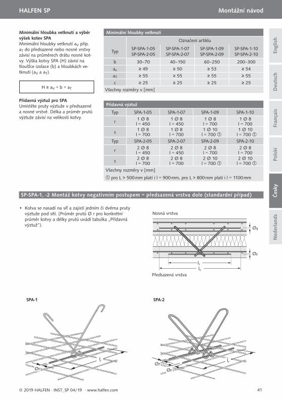
Minimální hloubka vetknutí a výběr výšek kotev SPA Minimální hloubky vetknutí aV příp. aT do předsazené nebo nosné vrstvy závisí na průměrech drátu nosné kot-vy. Výška kotvy SPA (H) závisí na tloušťce izolace (b) a hloubkách ve-tknutí (aV a aT).
Přídavná výztuž pro SPAUmístěte pruty výztuže v předsazené a nosné vrstvě. Délka a průměr prutů výztuže závisí na velikosti kotvy.
Minimální hloubky vetknutí
Označení artiklu
TypSP-SPA-1-05 SP-SPA-2-05
SP-SPA-1-07 SP-SPA-2-07
SP-SPA-1-09SP-SPA-2-09
SP-SPA-1-10SP-SPA-2-10
b 30–70 40–150 60–250 200–300
av ≥ 49 ≥ 50 ≥ 53 ≥ 54
aT ≥ 55 ≥ 55 ≥ 55 ≥ 55
c ≥ 25 ≥ 25 ≥ 25 ≥ 25
Všechny rozměry v [mm]
Přídavná výztuž
Typ SPA-1-05 SPA-1-07 SPA-1-09 SPA-1-10
r 1 Ø 8 1 Ø 8 1 Ø 8 1 Ø 8l = 450 l = 450 l = 700 l = 700
s 1 Ø 8 1 Ø 8 1 Ø 10 1 Ø 10l = 700 l = 700 l = 700 l = 700
Typ SPA-2-05 SPA-2-07 SPA-2-09 SPA-2-10
r 2 Ø 8 2 Ø 8 2 Ø 8 2 Ø 8l = 450 l = 450 l = 700 l = 700
s 2 Ø 8 2 Ø 8 2 Ø 10 2 Ø 10l = 700 l = 700 l = 700 l = 700
Všechny rozměry v [mm]
pro L > 500 mm platí i l = 900 mm, pro L > 800 mm platí i l = 1100 mm
H ≥ aV + b + aT
SP-SPA-1, -2 Montáž kotvy negativním postupem = předsazená vrstva dole (standardní případ)
• Kotva se nasadí na síť a zajistí jedním či dvěma pruty výztuže pod sítí. (Průměr prutů Ø r pro konkrétní průměr kotvy a délky prutů uvádí tabulka „Přídavná výztuž“).
SPA-1 SPA-2
Před
saze
ná v
rstv
a
Nos
ná v
rstv
a
f ≥ 60 b ≥ 100
≥ 50≥ 5 ≥ 55 ≥ 50av aT
Před
saze
ná v
rstv
a
Nos
ná v
rstv
a
f ≥ 60 b ≥ 100
≥ 35≥ 30 * ≥ 30 * ≥ 65
av
aT
Před
saze
ná v
rstv
a
Nos
ná v
rstv
a
f ≥ 60 b ≥ 100
≥ 5≥ 30 * ≥ 30 * ≥ 55
av
aT
42
HALFEN SP Montážní návod D
euts
chEn
glis
hFr
ança
isPo
lski
Čes
kyN
eder
land
s
© 2019 HALFEN · INST_SP 04/19 · www.halfen.com
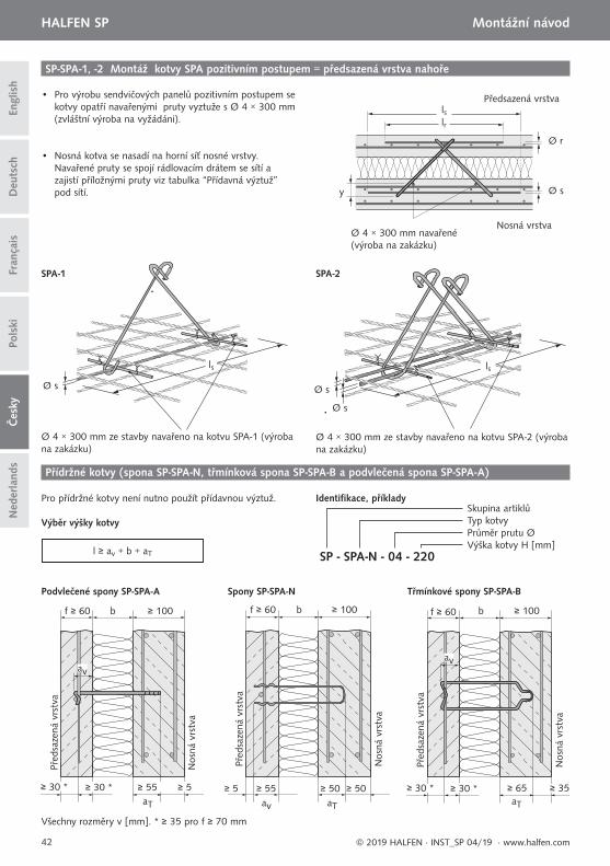
SP-SPA-1, -2 Montáž kotvy SPA pozitivním postupem = předsazená vrstva nahoře
• Pro výrobu sendvičových panelů pozitivním postupem se kotvy opatří navařenými pruty vyztuže s Ø 4 × 300 mm (zvláštní výroba na vyžádáni).
• Nosná kotva se nasadí na horní síť nosné vrstvy. Navařené pruty se spojí rádlovacím drátem se sítí a zajistí příložnými pruty viz tabulka “Přídavná výztuž” pod sítí.
Ø 4 × 300 mm navařené (výroba na zakázku)
Předsazená vrstva
Nosná vrstva
lrls
Ø r
Ø sy
Ø 4 × 300 mm ze stavby navařeno na kotvu SPA-1 (výroba na zakázku)
Ø 4 × 300 mm ze stavby navařeno na kotvu SPA-2 (výroba na zakázku)
Ø s Ø s
Ø s
SPA-1 SPA-2
ls ls
Přídržné kotvy (spona SP-SPA-N, třmínková spona SP-SPA-B a podvlečená spona SP-SPA-A)
Pro přídržné kotvy není nutno použít přídavnou výztuž.
Výběr výšky kotvy
l ≥ av + b + aT SP - SPA-N - 04 - 220
Skupina artiklůTyp kotvyPrůměr prutu ØVýška kotvy H [mm]
Identifi kace, příklady
Všechny rozměry v [mm]. * ≥ 35 pro f ≥ 70 mm
Podvlečené spony SP-SPA-A Spony SP-SPA-N Třmínkové spony SP-SPA-B
43
HALFEN SP Montážní návod
Deu
tsch
Čes
kyEn
glis
hPo
lski
Fran
çais
Ned
erla
nds
© 2019 HALFEN · INST_SP 04/19 · www.halfen.com
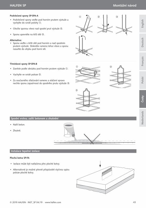
Podvlečené spony SP-SPA-A
Třmínkové spony SP-SPA-B
• Podvlečené spony veďte pod horním prutem výztuže a vychylte do svislé polohy .
• Otočte sponou vlevo nad spodní prut výztuže .
• Sponu upevněte na kříž sítě .
Alternativa: • Sponu veďte v kříži sítě pod horním a nad spodním prutem výztuže. Stiskněte rameno lehce vlevo a sponu nasuňte do ohybu pod horní sítí.
• Zavěste podle obrázku pod horním prutem výztuže .
• Vychylte ve svislé poloze .
• Za současného stlačování ramene a otáčení vpravo nechte sponu zapad-nout do spodního prutu výztuže .
Spodní vrstva; zalítí betonem a zhutnění
Instalace tepelné izolace
Plochá kotva SP-FA
• Izolace může být natlačena přes ploché kotvy.
• Alternativně je možné přesně přizpůsobit styčnou spáru poloze ploché kotvy.
• Nalít beton.
• Zhutnit.
44
HALFEN SP Montážní návod D
euts
chEn
glis
hFr
ança
isPo
lski
Čes
kyN
eder
land
s
© 2019 HALFEN · INST_SP 04/19 · www.halfen.com
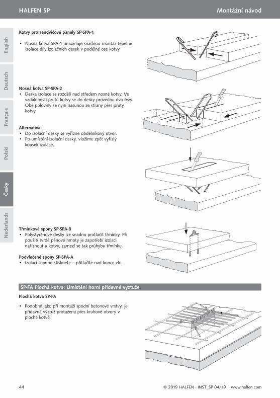
Třmínkové spony SP-SPA-B• Polystyrénové desky lze snadno protlačit třmínky. Při použití tvrdé pěnové hmoty je zapotřebí izolaci naříznout u kotvy, zamezí se tak průhybu třmínku.
Podvlečené spony SP-SPA-A• Izolaci snadno stisknete – přitlačíte nad konce vln.
Kotvy pro sendvičové panely SP-SPA-1
• Nosná kotva SPA-1 umožňuje snadnou montáž tepelné izolace díly izolačních desek v podélné ose kotvy
Nosná kotva SP-SPA-2• Deska izolace se rozdělí nad středem nosné kotvy. Ve vzdálenosti prutů kotvy se do desky provedou dva řezy. Obě poloviny se nyní nasunou ze strany přes pruty kotvy.
Plochá kotva SP-FA
• Do izolační desky se vyřízne obdélníkový otvor.• Po umístění izolační desky, vložíme zpět vyřízlý kousek izolace.
SP-FA Plochá kotva: Umístění horní přídavné výztuže
• Podobně jako při montáži spodní betonové vrstvy, je přídavná výztuž protažena přes kruhové otvory v ploché kotvě.
Alternativa:
45
HALFEN SP Montážní návod
Deu
tsch
Čes
kyEn
glis
hPo
lski
Fran
çais
Ned
erla
nds
© 2019 HALFEN · INST_SP 04/19 · www.halfen.com
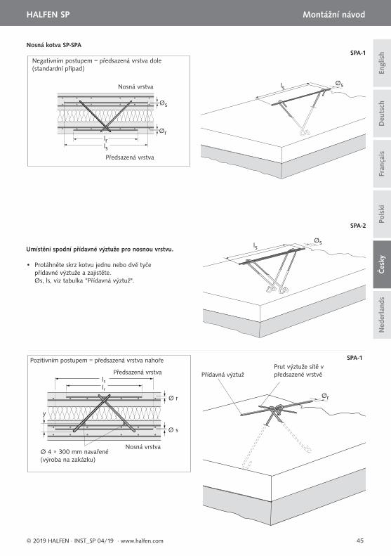
Nosná kotva SP-SPA
Pozitivním postupem = předsazená vrstva nahoře
lsØs
Ør
SPA-1
SPA-2
lrls
Ø r
Ø s
y
lsØs
SPA-1Negativním postupem = předsazená vrstva dole (standardní případ)
lrls
Øs
Ør
• Protáhněte skrz kotvu jednu nebo dvě tyče přídavné výztuže a zajistěte. Øs, ls, viz tabulka “Přídavná výztuž".
Umístění spodní přídavné výztuže pro nosnou vrstvu.
Přídavná výztužPrut výztuže sítě v předsazené vrstvě
Nosná vrstva
Nosná vrstva
Předsazená vrstva
Předsazená vrstva
Ø 4 × 300 mm navařené (výroba na zakázku)
46
HALFEN SP Montážní návod D
euts
chEn
glis
hFr
ança
isPo
lski
Čes
kyN
eder
land
s
© 2019 HALFEN · INST_SP 04/19 · www.halfen.com
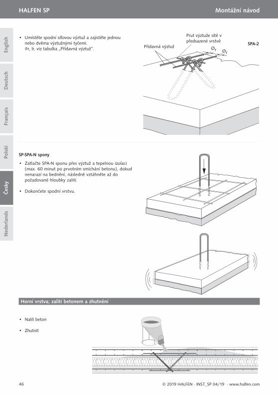
• Umístěte spodní síťovou výztuž a zajistěte jednou nebo dvěma výztužnými tyčemi. ∅r, lr, viz tabulka „Přídavná výztuž“. Ør Ør
SPA-2
• Zatlačte SPA-N sponu přes výztuž a tepelnou izolaci (max. 60 minut po prvotním smíchání betonu), dokud nenarazí na bednění, následně vztáhněte až do požadované hloubky zalití.
• Dokončete spodní vrstvu.
• Nalít beton
• Zhutnit
Horní vrstva; zalití betonem a zhutnění
SP-SPA-N spony
Přídavná výztuž
Prut výztuže sítě v předsazené vrstvě
47
HALFEN SP Montagehandleiding
Deu
tsch
Engl
ish
Pols
kiFr
ança
isČ
esky
Ned
erla
nds
© 2019 HALFEN · INST_SP 04/19 · www.halfen.com
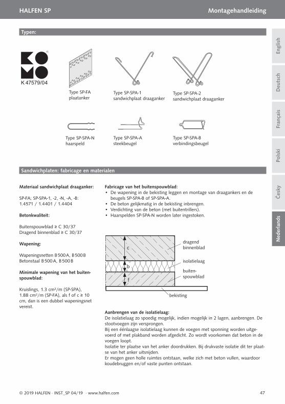
Typen:
Type SP-FA plaatanker
Type SP-SPA-N haarspeld
Type SP-SPA-2 sandwichplaat draaganker
Type SP-SPA-1 sandwichplaat draaganker
Type SP-SPA-A steekbeugel
Type SP-SPA-B verbindingsbeugel
Sandwichplaten: fabricage en materialen
Fabricage van het buitenspouwblad:• De wapening in de bekisting leggen en montage van draagankers en de beugels SP-SPA-B of SP-SPA-A.• De beton gelijkmatig in de bekisting inbrengen.• Verdichting van de beton (met buitentrillers).• Haarspelden SP-SPA-N worden later ingestoken.
Materiaal sandwichplaat draaganker:
SP-FA; SP-SPA-1, -2, -N, -A, -B: 1.4571 / 1.4401 / 1.4404
Betonkwaliteit:
Buitenspouwblad ≥ C 30/37Dragend binnenblad ≥ C 30/37
Wapening:
Wapeningsnetten B 500 A, B 500 BBetonstaal B 500 A, B 500 B
Minimale wapening van het buiten-spouwblad:
Kruislings, 1.3 cm²/m (SP-SPA), 1.88 cm²/m (SP-FA), als f of c ≥ 10 cm, dan is een dubbel wapeningsnet vereist.
dragend binnenblad
isolatielaag
bekisting
buiten-spouwblad
c
b
f
Aanbrengen van de isolatielaag:De isolatielaag zo spoedig mogelijk, indien mogelijk in 2 lagen, aanbrengen. De stootvoegen zijn versprongen.Bij een éénlaagse isolatielaag kunnen de voegen met sponning worden uitge-voerd of met plakband worden afgedicht. Zo wordt voorkomen dat beton in de voegen loopt.Isolatie ter plaatse van het anker doordrukken. Bij drukvaste isolatie dit ter plaat-se van het anker uitsnijden. Er mogen geen holle ruimtes ontstaan, welke zich met beton vullen, waardoor koudebruggen en/of vaste punten ontstaan.
K 47579/04
R
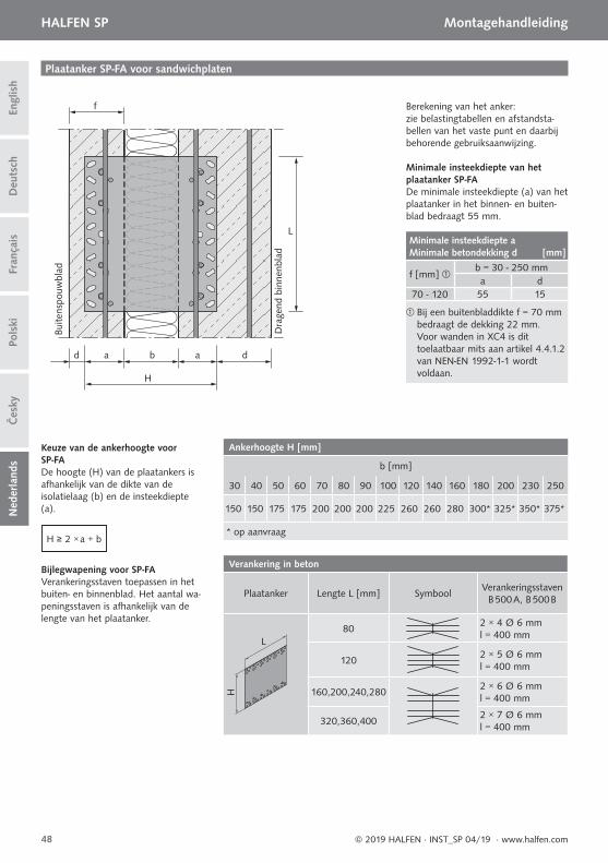
d a a d
L
f
b
H
48
HALFEN SP MontagehandleidingD
euts
chEn
glis
hFr
ança
isPo
lski
Čes
kyN
eder
land
s
© 2019 HALFEN · INST_SP 04/19 · www.halfen.com
Plaatanker SP-FA voor sandwichplaten
Dra
gend
bin
nenb
lad
Buite
nspo
uwbl
ad
Berekening van het anker: zie belastingtabellen en afstandsta-bellen van het vaste punt en daarbij behorende gebruiksaanwijzing.
Minimale insteekdiepte van het plaatanker SP-FADe minimale insteekdiepte (a) van het plaatanker in het binnen- en buiten-blad bedraagt 55 mm.
H ≥ 2 × a + b
De hoogte (H) van de plaatankers isafhankelijk van de dikte van de isolatielaag (b) en de insteekdiepte (a).
Keuze van de ankerhoogte voor SP-FA
Verankeringsstaven toepassen in het buiten- en binnenblad. Het aantal wa-peningsstaven is afhankelijk van de lengte van het plaatanker.
Bijlegwapening voor SP-FA
Ankerhoogte H [mm]
b [mm]
30 40 50 60 70 80 90 100 120 140 160 180 200 230 250
150 150 175 175 200 200 200 225 260 260 280 300* 325* 350* 375*
* op aanvraag
Verankering in beton
Plaatanker Lengte L [mm] SymboolVerankeringsstaven
B 500 A, B 500 B
L
H
802 × 4 Ø 6 mml = 400 mm
1202 × 5 Ø 6 mml = 400 mm
160,200,240,2802 × 6 Ø 6 mml = 400 mm
320,360,4002 × 7 Ø 6 mml = 400 mm
Minimale insteekdiepte a Minimale betondekking d [mm]
f [mm] b = 30 - 250 mma d
70 - 120 55 15
Bij een buitenbladdikte f = 70 mm bedraagt de dekking 22 mm.Voor wanden in XC4 is dit toelaatbaar mits aan artikel 4.4.1.2 van NEN-EN 1992-1-1 wordt voldaan.
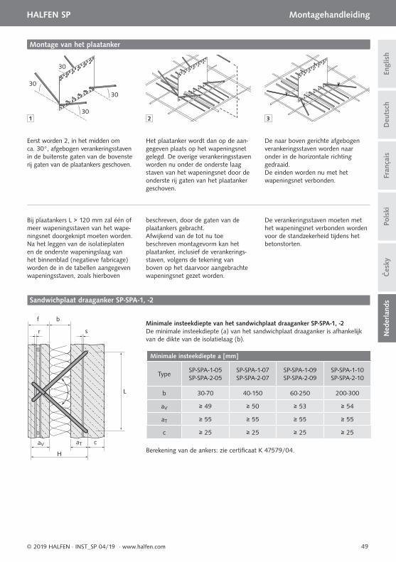
30
30
30
30
1 2 3
b
sr
f
L
aV aT c
H
49
HALFEN SP Montagehandleiding
Deu
tsch
Engl
ish
Pols
kiFr
ança
isČ
esky
Ned
erla
nds
© 2019 HALFEN · INST_SP 04/19 · www.halfen.com
Montage van het plaatanker
Eerst worden 2, in het midden om ca. 30°, afgebogen verankeringsstaven in de buitenste gaten van de bovenste rij gaten van de plaatankers geschoven.
Het plaatanker wordt dan op de aan-gegeven plaats op het wapeningsnet gelegd. De overige verankeringsstaven worden nu onder de onderste laag staven van het wapeningsnet door de onderste rij gaten van het plaatanker geschoven.
De naar boven gerichte afgebogenverankeringsstaven worden naar onder in de horizontale richting gedraaid.De einden worden nu met het wapeningsnet verbonden.
Bij plaatankers L > 120 mm zal één of meer wapeningsstaven van het wape-ningsnet doorgeknipt moeten worden.Na het leggen van de isolatieplaten en de onderste wapeningslaag van het binnenblad (negatieve fabricage) worden de in de tabellen aangegeven wapeningsstaven, zoals hierboven
beschreven, door de gaten van deplaatankers gebracht.Afwijkend van de tot nu toe beschreven montagevorm kan het plaatanker, inclusief de verankerings-staven, volgens de tekening van boven op het daarvoor aangebrachtewapeningsnet gezet worden.
De verankeringsstaven moeten met het wapeningsnet verbonden worden voor de standzekerheid tijdens het betonstorten.
Sandwichplaat draaganker SP-SPA-1, -2
Minimale insteekdiepte van het sandwichplaat draaganker SP-SPA-1, -2De minimale insteekdiepte (a) van het sandwichplaat draaganker is afhankelijk van de dikte van de isolatielaag (b).
Minimale insteekdiepte a [mm]
TypeSP-SPA-1-05SP-SPA-2-05
SP-SPA-1-07SP-SPA-2-07
SP-SPA-1-09SP-SPA-2-09
SP-SPA-1-10SP-SPA-2-10
b 30-70 40-150 60-250 200-300
aV ≥ 49 ≥ 50 ≥ 53 ≥ 54
aT ≥ 55 ≥ 55 ≥ 55 ≥ 55
c ≥ 25 ≥ 25 ≥ 25 ≥ 25
Berekening van de ankers: zie certifi caat K 47579/04.
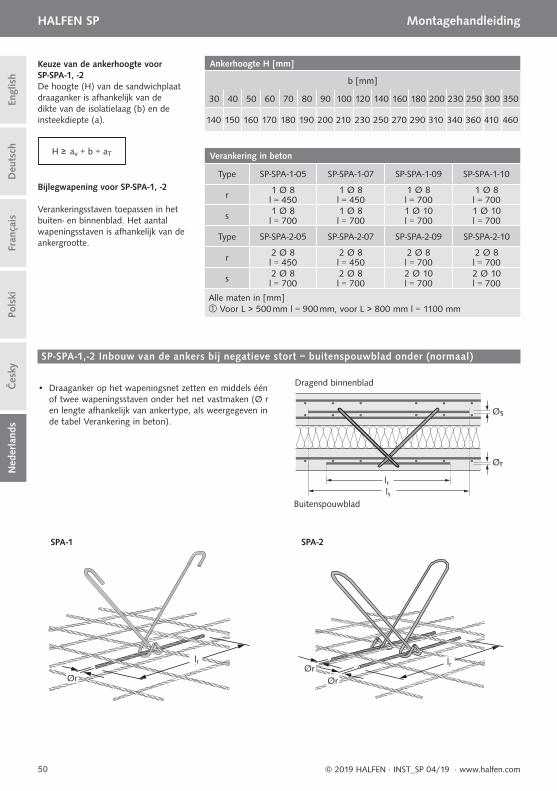
lrØrØr
lrlr
Ør
Dragend binnenblad
Buitenspouwblad
Øs
Ør
lslr
50
HALFEN SP MontagehandleidingD
euts
chEn
glis
hFr
ança
isPo
lski
Čes
kyN
eder
land
s
© 2019 HALFEN · INST_SP 04/19 · www.halfen.com
H ≥ av + b + aT
De hoogte (H) van de sandwichplaat draaganker is afhankelijk van de dikte van de isolatielaag (b) en de insteekdiepte (a).
Keuze van de ankerhoogte voor SP-SPA-1, -2
Verankeringsstaven toepassen in het buiten- en binnenblad. Het aantal wapeningsstaven is afhankelijk van de ankergrootte.
Bijlegwapening voor SP-SPA-1, -2
Ankerhoogte H [mm]
b [mm]
30 40 50 60 70 80 90 100 120 140 160 180 200 230 250 300 350
140 150 160 170 180 190 200 210 230 250 270 290 310 340 360 410 460
Verankering in beton
Type SP-SPA-1-05 SP-SPA-1-07 SP-SPA-1-09 SP-SPA-1-10
r 1 Ø 8 1 Ø 8 1 Ø 8 1 Ø 8l = 450 l = 450 l = 700 l = 700
s 1 Ø 8 1 Ø 8 1 Ø 10 1 Ø 10l = 700 l = 700 l = 700 l = 700
Type SP-SPA-2-05 SP-SPA-2-07 SP-SPA-2-09 SP-SPA-2-10
r 2 Ø 8 2 Ø 8 2 Ø 8 2 Ø 8l = 450 l = 450 l = 700 l = 700
s 2 Ø 8 2 Ø 8 2 Ø 10 2 Ø 10l = 700 l = 700 l = 700 l = 700
Alle maten in [mm] Voor L > 500 mm l = 900 mm, voor L > 800 mm l = 1100 mm
SP-SPA-1,-2 Inbouw van de ankers bij negatieve stort = buitenspouwblad onder (normaal)
• Draaganker op het wapeningsnet zetten en middels één of twee wapeningsstaven onder het net vastmaken (Ø r en lengte afhankelijk van ankertype, als weergegeven in de tabel Verankering in beton).
SPA-1 SPA-2
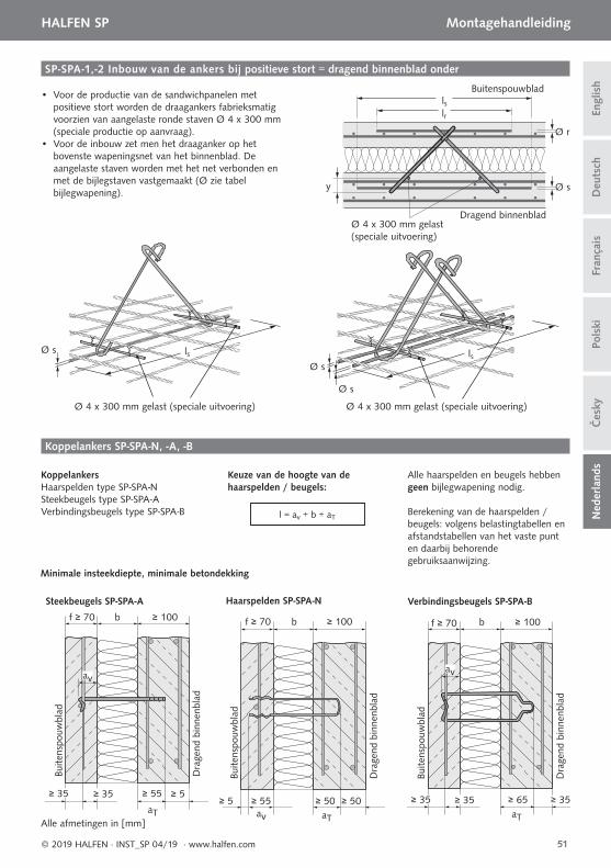
Ø s
Ø s
lsØ s ls
f ≥ 70
Buite
nspo
uwbl
ad
Dra
gend
bin
nenb
lad
av
aT
Buite
nspo
uwbl
ad
Dra
gend
bin
nenb
lad
f ≥ 70 b ≥ 100
≥ 50≥ 5 ≥ 55 ≥ 50av aT aT
Buite
nspo
uwbl
ad
Dra
gend
bin
nenb
lad
f ≥ 70 b ≥ 100
≥ 35≥ 35 ≥ 35 ≥ 65
av
b ≥ 100
≥ 5≥ 35 ≥ 35 ≥ 55
Haarspelden SP-SPA-N Verbindingsbeugels SP-SPA-B Steekbeugels SP-SPA-A
Alle afmetingen in [mm]
51
HALFEN SP Montagehandleiding
Deu
tsch
Engl
ish
Pols
kiFr
ança
isČ
esky
Ned
erla
nds
© 2019 HALFEN · INST_SP 04/19 · www.halfen.com
KoppelankersHaarspelden type SP-SPA-N Steekbeugels type SP-SPA-A Verbindingsbeugels type SP-SPA-B
Keuze van de hoogte van de haarspelden / beugels:
Alle haarspelden en beugels hebben geen bijlegwapening nodig.
Berekening van de haarspelden / beugels: volgens belastingtabellen en afstandstabellen van het vaste punt en daarbij behorende gebruiksaanwijzing.
Koppelankers SP-SPA-N, -A, -B
l = av + b + aT
SP-SPA-1,-2 Inbouw van de ankers bij positieve stort = dragend binnenblad onder
• Voor de productie van de sandwichpanelen met positieve stort worden de draagankers fabrieksmatig voorzien van aangelaste ronde staven Ø 4 x 300 mm (speciale productie op aanvraag).
• Voor de inbouw zet men het draaganker op het bovenste wapeningsnet van het binnenblad. De aangelaste staven worden met het net verbonden en met de bijlegstaven vastgemaakt (Ø zie tabel bijlegwapening).
Ø 4 x 300 mm gelast (speciale uitvoering) Ø 4 x 300 mm gelast (speciale uitvoering)
Minimale insteekdiepte, minimale betondekking
Ø 4 x 300 mm gelast (speciale uitvoering)
Buitenspouwblad
Dragend binnenblad
lrls
Ø r
Ø sy
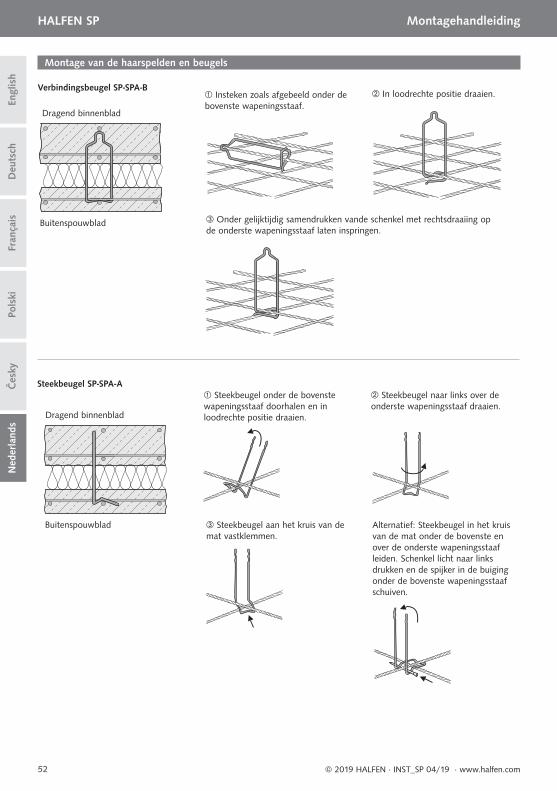
52
HALFEN SP MontagehandleidingD
euts
chEn
glis
hFr
ança
isPo
lski
Čes
kyN
eder
land
s
© 2019 HALFEN · INST_SP 04/19 · www.halfen.com
Montage van de haarspelden en beugels
Dragend binnenblad
Dragend binnenblad
Buitenspouwblad
Buitenspouwblad
Verbindingsbeugel SP-SPA-B Insteken zoals afgebeeld onder debovenste wapeningsstaaf.
In loodrechte positie draaien.
Onder gelijktijdig samendrukken vande schenkel met rechtsdraaiing opde onderste wapeningsstaaf laten inspringen.
Steekbeugel SP-SPA-A Steekbeugel onder de bovenste wapeningsstaaf doorhalen en in loodrechte positie draaien.
Steekbeugel naar links over de onderste wapeningsstaaf draaien.
Steekbeugel aan het kruis van de mat vastklemmen.
Alternatief: Steekbeugel in het kruis van de mat onder de bovenste en over de onderste wapeningsstaaf leiden. Schenkel licht naar links drukken en de spijker in de buiging onder de bovenste wapeningsstaaf schuiven.
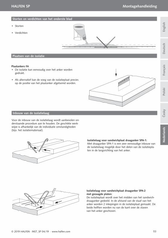
53
HALFEN SP Montagehandleiding
Deu
tsch
Engl
ish
Pols
kiFr
ança
isČ
esky
Ned
erla
nds
© 2019 HALFEN · INST_SP 04/19 · www.halfen.com
Plaatsen van de isolatie
Plaatankers FA • De isolatie kan eenvoudig over het anker worden
gedrukt.
• Als alternatief kan de voeg van de isolatieplaat precies op de positie van het plaatanker afgetsemd worden.
• Storten
• Verdichten
Storten en verdichten van het onderste blad
Inbouw van de isolatielaag
Voor de inbouw van de isolatielaag wordt aanbevolen on-derstaande procedure aan te houden. De geschikte werk-wijze is afhankelijk van de individuele omstandigheden (bijv. het isolatiemateriaal).
Isolatielaag voor sandwichplaat draaganker SPA-1:Met draaganker SPA-1 is een zeer eenvoudige inbouw van de isolatielaag mogelijk door het delen van de isolatiepla-ten in de langsrichting van het anker.
Isolatielaag voor sandwichplaat draaganker SPA-2met gezaagde platen:De isolatieplaat wordt over het midden van het sandwich-draaganker gedeeld. In de afstand van de staaf van hetanker worden 2 inkepingen in de isolatieplaat gemaakt. De beide helften worden nu van de kant over de stavenvan het anker geschoven.
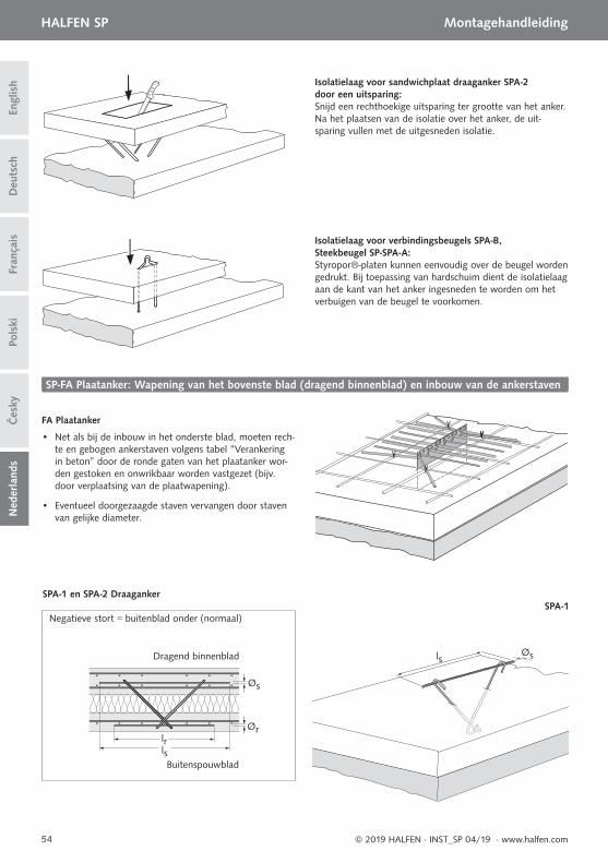
54
HALFEN SP MontagehandleidingD
euts
chEn
glis
hFr
ança
isPo
lski
Čes
kyN
eder
land
s
© 2019 HALFEN · INST_SP 04/19 · www.halfen.com
Isolatielaag voor sandwichplaat draaganker SPA-2 door een uitsparing:Snijd een rechthoekige uitsparing ter grootte van het anker.Na het plaatsen van de isolatie over het anker, de uit-sparing vullen met de uitgesneden isolatie.
Isolatielaag voor verbindingsbeugels SPA-B, Steekbeugel SP-SPA-A:Styropor®-platen kunnen eenvoudig over de beugel worden gedrukt. Bij toepassing van hardschuim dient de isolatielaag aan de kant van het anker ingesneden te worden om het verbuigen van de beugel te voorkomen.
SP-FA Plaatanker: Wapening van het bovenste blad (dragend binnenblad) en inbouw van de ankerstaven
FA Plaatanker
• Net als bij de inbouw in het onderste blad, moeten rech-te en gebogen ankerstaven volgens tabel “Verankering in beton” door de ronde gaten van het plaatanker wor-den gestoken en onwrikbaar worden vastgezet (bijv. door verplaatsing van de plaatwapening).
• Eventueel doorgezaagde staven vervangen door staven van gelijke diameter.
lsØs
SPA-1Negatieve stort = buitenblad onder (normaal)
Dragend binnenblad
Buitenspouwblad
lrls
Øs
Ør
SPA-1 en SPA-2 Draaganker
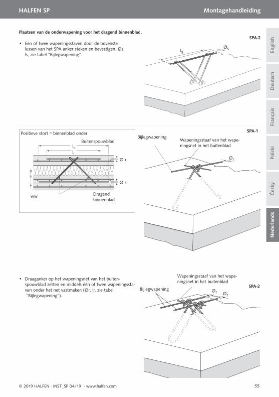
55
HALFEN SP Montagehandleiding
Deu
tsch
Engl
ish
Pols
kiFr
ança
isČ
esky
Ned
erla
nds
© 2019 HALFEN · INST_SP 04/19 · www.halfen.com
Positieve stort = binnenblad onderBijlegwapening
Wapeningsstaaf van het wape-ningsnet in het buitenblad
• Eén of twee wapeningsstaven door de bovenste lussen van het SPA anker steken en bevestigen. Øs, ls, zie tabel “Bijlegwapening”.
lsØs
Ør
Plaatsen van de onderwapening voor het dragend binnenblad.
SPA-1
SPA-2
ww Dragend binnenblad
Buitenspouwblad
lrls
Ø r
Ø s
y
Bijlegwapening
Wapeningsstaaf van het wape-ningsnet in het buitenblad
• Draaganker op het wapeningsnet van het buiten-spouwblad zetten en middels één of twee wapeningssta-ven onder het net vastmaken (Ør, lr, zie tabel “Bijlegwapening”).
Ør Ør
SPA-2
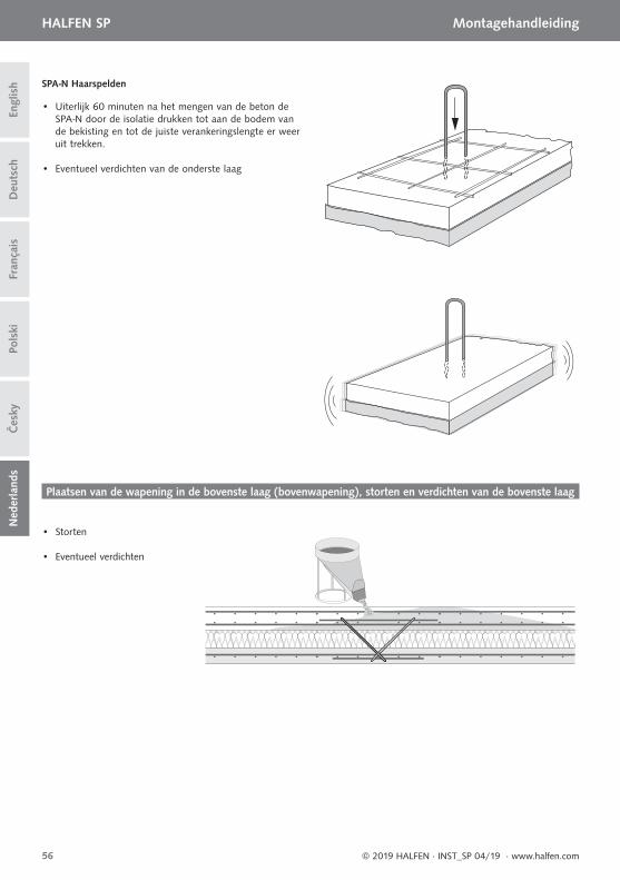
56
HALFEN SP MontagehandleidingD
euts
chEn
glis
hFr
ança
isPo
lski
Čes
kyN
eder
land
s
© 2019 HALFEN · INST_SP 04/19 · www.halfen.com
• Uiterlijk 60 minuten na het mengen van de beton de SPA-N door de isolatie drukken tot aan de bodem van de bekisting en tot de juiste verankeringslengte er weer uit trekken.
SPA-N Haarspelden
• Eventueel verdichten van de onderste laag
• Storten
• Eventueel verdichten
Plaatsen van de wapening in de bovenste laag (bovenwapening), storten en verdichten van de bovenste laag

57

58
NOTES REGARDING THIS DOCUMENTTechnical and design changes reserved. The information in this publication is based on state-of-the-art technology at the time of publication. We reserve the right to make technical and design changes at any time. HALFEN GmbH shall not accept liability for the accuracy of the information in this publication or for any printing errors.
The HALFEN GmbH subsidiaries in Germany, France, the Netherlands, Austria, Poland, Switzerland and the Czech Republic are Quality Management certifi ed according to ISO 9001:2015, Certifi cate no. 202384-2016-AQ-GER-DAkkS.
Furthermore HALFEN is represented with sales offi ces and distributors worldwide. Please contact us: www.halfen.com
Austria HALFEN Gesellschaft m.b.H.Leonard-Bernstein-Str. 101220 Wien
Phone: +43 - 1 - 259 6770 E-Mail: offi [email protected]: www.halfen.at
Belgium /Luxembourg
HALFEN N.V.Borkelstraat 1312900 Schoten
Phone: +32 - 3 - 658 07 20E-Mail: [email protected]: www.halfen.be
Fax: +32 - 3 - 658 15 33
China HALFEN Construction Accessories Distribution Co.Ltd.Room 601 Tower D, Vantone CentreNo.A6 Chao Yang Men Wai StreetChaoyang District Beijing · P.R. China 100020
Phone: +86 - 10 5907 3200E-Mail: [email protected]: www.halfen.cn
Fax: +86 - 10 5907 3218
Czech Republic HALFEN s.r.o.Business Center ŠafránkovaŠafránkova 1238/1155 00 Praha 5
Phone: +420 - 311 - 690 060E-Mail: [email protected]: www.halfen.cz
Fax: +420 - 235 - 314308
France HALFEN S.A.S.18, rue Goubet75019 Paris
Phone: +33 - 1 - 445231 00E-Mail: [email protected]: www.halfen.fr
Fax: +33 - 1 - 445231 52
Germany HALFEN Vertriebsgesellschaft mbHLiebigstr. 14 40764 Langenfeld
Phone: +49 - 2173 - 970 0E-Mail: [email protected]: www.halfen.de
Fax: +49 - 2173-970 225
Italy HALFEN S.r.l. Soc. UnipersonaleVia F.lli Bronzetti N° 2824124 Bergamo
Phone: +39 - 035 - 0760711E-Mail: [email protected]: www.halfen.it
Fax: +39 - 035 - 0760799
Netherlands HALFEN b.v.Oostermaat 37623 CS Borne
Phone: +31 - 74-267 14 49E-Mail: [email protected]: www.halfen.nl
Fax: +31 - 74-2 67 26 59
Norway HALFEN ASPostboks 20804095 Stavanger
Phone: +47 - 51 82 34 00E-Mail: [email protected]: www.halfen.no
Poland HALFEN Sp. z o.o.Ul. Obornicka 28760-691 Poznan
Phone: +48 - 61 - 622 14 14E-Mail: [email protected]: www.halfen.pl
Fax: +48 - 61 - 622 14 15
Spain HALFEN IBERICA, S.L.Polígono Industrial Santa Ana c/ Ignacio Zuloaga 2028522 Rivas-Vaciamadrid
Phone: +34 - 91 632 18 40E-Mail: [email protected]: www.halfen.es
Fax: +34 - 91 633 42 57
Sweden Halfen ABVädursgatan 5412 50 Göteborg
Phone: +46 - 31 - 98 58 00E-Mail: [email protected]: www.halfen.se
Fax: +46 - 31 - 98 58 01
Switzerland HALFEN Swiss AGHertistrasse 25 8304 Wallisellen
Phone: +41 - 44 - 849 78 78E-Mail: [email protected]: www.halfen.ch
Fax: +41 - 44 - 849 78 79
United Kingdom /Ireland
HALFEN Ltd.A1/A2 Portland CloseHoughton Regis LU5 5AW
Phone: +44 - 1582 - 47 03 00E-Mail: [email protected]: www.halfen.co.uk
Fax: +44 - 1582 - 47 03 04
United States of America
HALFEN USA Inc. PO Box 18687 San Antonio TX 78218
Phone: +1 800.423.91 40E-Mail: [email protected]: www.halfenusa.com
Fax: +1 877.683.4910
For countries not listed HALFEN International
HALFEN International GmbHLiebigstr. 14 40764 Langenfeld / Germany
Phone: +49 - 2173 - 970 - 0 E-Mail: [email protected]: www.halfen.com
Fax: +49 - 2173 - 970 - 849
CONTACT HALFEN WORLDWIDE
HALFEN is represented by subsidiaries in the following countries, please contact us
www.dnvgl.com

© 2
019
HA
LFEN
Gm
bH, G
erm
any
appl
ies
also
to
copy
ing
in e
xtra
cts.
U -
250
- 12/
19