Embed Size (px)
Citation preview

25.06.2012 Errors and modifications reserved
Zum Aufbau benötigen Sie folgende Werkzeuge:For mounting use following tools:
Innensechskantschlüssel-Satzallen key
Â=2; Â=2,5; Â=3; Â=6; Â=9;
Â=10
(Drehmoment-)Schraubenschlüsselscrew-wrenchSW 7; SW 16
Maßbandmeasuring tape
Sicherungsklebstofflocking-glue
Schraubzwingescrew clamp
Technical SupportGermany:Tel.: +49 (0) 67 22 / 99 65 77Fax: +49 (0) 67 22 / 99 65 70email: [email protected]
Other countries, please contact your distributor.
Montageanleitung Schachtkopierung WDGMSUN
Mounting instruction for belt measuring system WDGMSUN
2
1
10
15
13
12
22
18
20
19
23
6
24
21
8
9
5
6
3 4
11
300
400
90
16
194.
25
16
24
9
7
25
26
Seite 1 von 4
14
1716
1.
2.
3.
4.
5.
Es dürfen nur die gelieferten Teile verbaut werden.
Es müssen alle Teile verbaut werden.
Montagehinweise:
Montage nur durch Fachpersonal.
Montage durch zwei Personen.
Alle Schraubverbindungen mit Sicherungsklebstoff (z.B. Loctite 243)
6.
7.
Die angegebenen Grenzwerte für die Anzugs-
Für die Funktion und die gerechte Montage ist
Keine Gewährleistung für die Montage des Systems.
momente und Federvorspannung dürfen nicht überschritten werden
allein das Montagepersonal verantwortlich.
8.
sichern.
A
D
E
C
B
Sicherheitshinweise:
1. Es sind die entsprechenden Sicherheits-vorschriften zu beachten!
2. Ohne Rollensicherung darf das Systemnicht in Betrieb genommen werden!
3. Die Federspannung des Systems darf den Wert von
100N nicht uebersteigen und 40N nicht unterschreiten
4. Nach Beendigung der Montage nochmal Federspannung
pruefen
ZZ
Teiledefinition siehe
Stückliste auf Seite 4Partdefinition refer
to parts list on page 4
Safety instructions:
1. All applicable safety regulations haveto be adhered to!
2. It is not allowed to put the System in operation without the pulley retention!
3. The spring tension of the system is not permitted
to trascend the value of 100N or to fall below 40N.
4. After installation the spring tension should be checked
again.
1.
2.
3.
4.
5.
It is only permitted to use provided parts
All provided parts have to be used.
Mounting advices:
Mounting only by qualified personnel
Mounting by two persons
Screw connections have to be locked with locking-glue
6.
7.
The prescriptive limits for clamping torque and
the operational reability and correct mounting.
No warranty to the mounting to the system.
spring tension have to be followed.
The mounting personnel is responsible for
8.
(e.g. Loctite 243).
Einheiten in mm
All dimensions in mm
page 1 of 4
24.07.201424.07.2014

Baugruppe -B- (siehe auch Seite 1) / Unit -B- (see also page 1)
Abstand 1-2 mm
2
3
13
Anzugsmoment/Nm:
h=M4
h=M4_Gewindestift
h=M8
h=M10
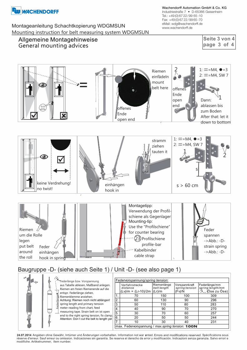
Allgemeine Montagehinweise
1 1: =M4, Â=2,5
2: h=M8, Â=6
3: h=M4, Â=2
h
1: =M10, Â=10
2: h=M10, SW 16
3: h=M8, Â=6
h
2
21
12
20
1
1
1: 4x =M10, SW 16
2: =Schraubzwinge
screw clamp
(Optional)
h
2
2
x
y 1
1 α
s
α>2°
s>10mm
x: = x=y (cm)
y: = y=x (cm)
1: h=M8, Â=6
Wichtig: Wenn der
Drehgeber
(Riemenscheibe) im
Schachtkopf montiert ist
Montageanleitung Schachtkopierung WDGMSUN
Mounting instruction for belt measuring system WDGMSUN
General mounting advices
clamping torque/Nm:
(Standard) muß die Feder unterhalb der
Befestigung am Korb liegen.
Bei Positionierung des Drehgebers in der
Schachtgrube muß die Feder oberhalb der
Befestigung am Korb liegen.
Important: If the encoder (pulley) should be
mounted in the upper part of the shaft
(standard) the spring has to be below the
fixing of the cabin. When positioning the
distance 1-2 mm
Baugruppe -C- (siehe auch Seite 1) / Unit -C- (see also page 1)
Baugruppe -A- (siehe auch Seite 1) / Unit -A- (see also page 1)
7 cm
raue Seite nach oben
rough side up
Seite 2 von 4page 2 of 4
25.06.2012 Errors and modifications reserved24.07.201424.07.2014
N
þ ý
=Riemen
einfädeln
mount
belt here
offenes
Ende
open end
offenes
Ende
open
end
1: =M4, Â=3
2: h=M4, SW 7
h
1
2
Dann:
ablassen bis
zum Boden
After that: let it
down to bottom
€
N þ
keine Verdrehung!
no twist!einhängen
hook in
stramm
ziehen
tauten it
s > 60 cm
s
1: =M4, Â=3
2: h=M4, SW 7
h
21
Feder
einhängen
hook in spring
Riemen
um die Rolle
legen
put belt
around
the roll
23 Profilschiene
profile-bar
Kabelbinder
cable strap
Fed
erl
än
ge
Federlänge bzw. Vorspannung
aus Tabelle ablesen, Maßband anlegen.
Riemen am freien Riemenende auf die
entspr. Federlänge ziehen,
Riemenklemme anziehen.Achtung: Riemen noch nicht ablängen!
spring length and primary tension
meter-reading from chart, feed
measuring tape. Strain belt on ist open
end to the right spring tension, fix clamp.Attention: Don´t cut the belt to length yet
distance (Lv)/m = (Lr-10)/2m
Riemenlänge
(Lr)/m
Vorspannkraft
(Fv)/N
Federlänge/mm
(Öse zu Öse)
1. 70 150 100 309
2. 60 130 90 296
3. 50 110 80 283
4. 40 90 70 270
5. 30 70 60 257
6. 20 50 50 244
7. 10 30 40 231
Federvorspannung/spring tension:
max. Federvorspannung / max.spring tension: 100N
Feder
spannen
->Abb.: -D-
strain spring
->Abb.: -D-
Montagetipp:
Verwendung der Profil-
schiene als GegenlagerMounting-tip:
Use the “Profilschiene”
for counter bearing
Montageanleitung Schachtkopierung WDGMSUN
Mounting instruction for belt measuring system WDGMSUN
Allgemeine MontagehinweiseGeneral mounting advices
Verfahrstrecke belt length spring tension spring length/mm
Baugruppe -D- (siehe auch Seite 1) / Unit -D- (see also page 1)
Seite 3 von 4page 3 of 4
25.06.2012 Errors and modifications reserved24.07.201424.07.2014

23 ,
Profilschiene
profile-bar
wieder ab-
montieren
demount
1: =M4, Â=3
2: h=M4, SW 7
3: h=M8, Â=9
h
1
23
Probefahrt
durchführen
perform a
testrun
MKTS4122M0-ZVK
MKBEH41850-ZVK
MKBEH41220-ZVK
MKBB000011-ZVK
US802024M0-ZVK
SC80IZ20A0-ZVK
SC40IF08Z0-ZVK
MKNS000010-ZVK
SC40GA04Z0-ZVK
MKBB000021-ZVK
MKUR000010-ZVK
LGT60002RS-ZVK
SEI26B0000-ZVK
MKDH101608-ZVK
SC10IZ50A0-ZVK
US101721A0-ZVK
MUAM100000-ZVK
MKBE000001-ZVK
MKBB000044-ZVK
SC40IZ20A0-ZVK
MUM0M40000-ZVK
FESF000000-ZVK
MKTS2012L0-ZVK
SC40IZ40A0-ZVK
MUA0M80000-ZVK
SCRS8030Z0-ZVK
1. 2 Profilschiene / Profile-bar 400mm
2. 4 Befestigungsklemme / Mounting clamp M10 41/55 fv
3. 4 Gewindeplatte / Thread base plate M8 41/41
4. 1 Befestigungsblech_WDG / Fixing plate_WDG
5. 4 Scheibe / Washer M8 DIN 9021
6. 6 Zylinderschraube / Socket cap screw M8x20-8.8 ISO 4762
7. 3 Zylinderschraube / Socket cap screw M4x8 DIN 7984
8. 1 Noppenscheibe / Nub washer
9. 2 Gewindestift / Threaded pin M4x4 DIN 913
10. 1 Befestigungsblech_Umlenkrolle / Fixing plate_pulley
11. 1 Umlenkrolle / Pulley
12. 1 Rillenkugellager / flute bearing
13. 1 Sicherungsring / Retaining ring
14. 1 Distanzhülse / Distance bush 10x16x8
15. 1 Zylinderschraube / Socket cap screw M10x50-8.8 DIN4762
16. 1 Scheibe / Washer M10 ISO 7092
17. 1 Sechskantmutter / Hex-nut M10 ISO 4032
18. 2 Riemenaufhängung / Belt suspension
19. 5 Riemenklemme / Belt clamp
20. 4 Zylinderschraube / Socket cap screw M4x20 DIN 912
21. 6 Sechskantmutter / Hex-nut M4 DIN 934
22. 1 Zugfeder / Tension spring
23. 1 Profilschiene / Profile-bar
24. 2 Zylinderschraube / Socket cap screw M4x40 DIN 912
25. 1 Sechskantmutter / Hex-nut M8 ISO 4032
26. 1 Rändelschraube / knurled screw DIN 653
Stückliste / parts list
Montageanleitung Schachtkopierung WDGMSUN
Mounting instruction for belt measuring system WDGMSUN
Allgemeine MontagehinweiseGeneral mounting advices
St.Nr. Bezeichnung / Description Artikelnr. / Part no.
Baugruppe -E- (siehe auch Seite 1) / Unit -E- (see also page 1)
Seite 4 von 4page 4 of 4
25.06.2012 Errors and modifications reserved24.07.201424.07.2014


![Erich Fromm: The Courage to Be Human - OPUS 4...Erich Fromm - The Courage to Be Human Rainer Funk Erich Fromm: The Courage to Be Human With a Postscript by Erich Fromm E-Mail: funk[at-symbol]fromm-online.com](https://img.pdfslide.org/doc/110x75/60837396f983a50b0c629828/erich-fromm-the-courage-to-be-human-opus-4-erich-fromm-the-courage-to-be.jpg)