Embed Size (px)
Citation preview
© PARI GmbH Spezialisten für effektive Inhalation 085D0065-A-12/13
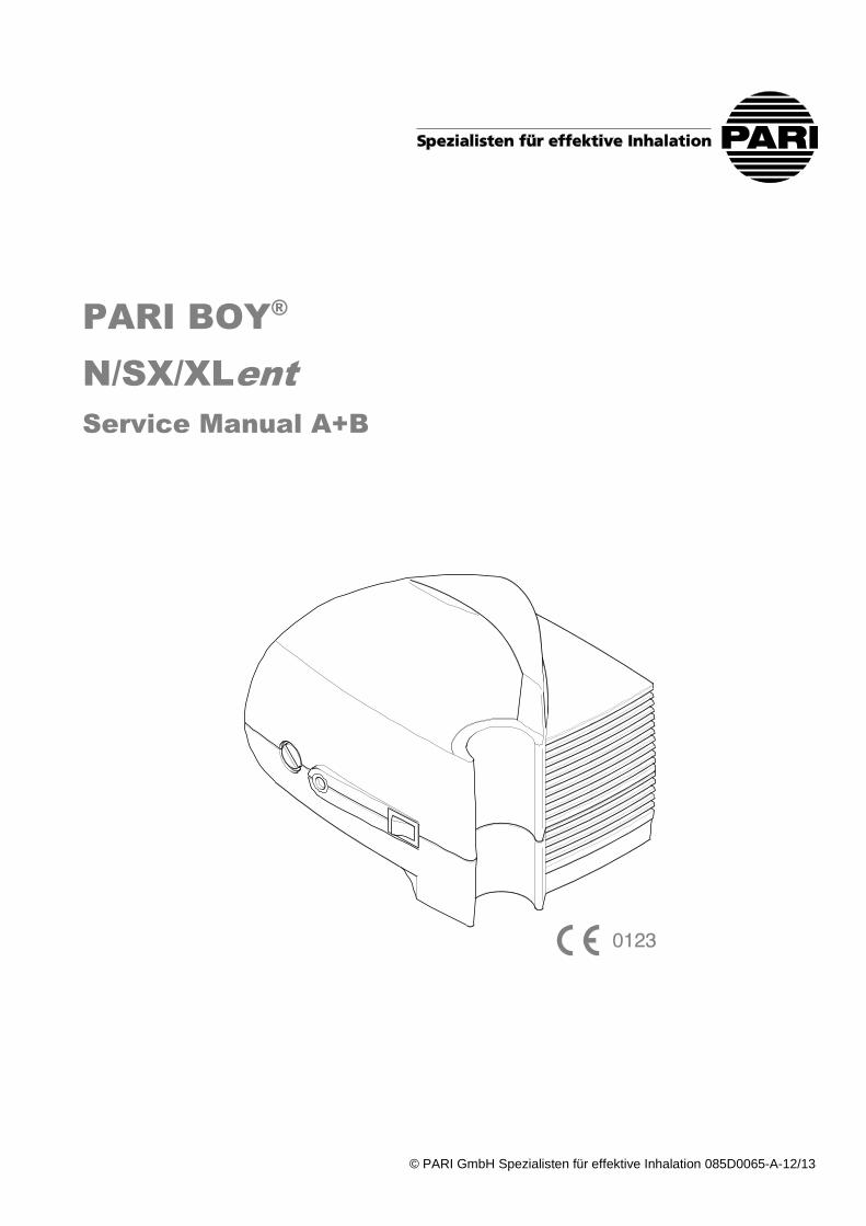
PARI BOY®
N/SX/XLent
Service Manual A+B
© PARI GmbH Spezialisten für effektive Inhalation 085D0065-A-07/09 2
Inhalt
Content
1. Allgemein ................................................................. 3 1.1. Sicherheitshinweise .................................................. 3 1.2. Hinweis zu den Ersatzteilen ...................................... 3 1.3. Spezifikationen .......................................................... 3 1.4. Benötigtes Werkzeug ................................................ 3 1.5. Drehmomente ........................................................... 3
2. Gehäuse ................................................................... 4 2.1. Gehäuse öffnen/schließen ........................................ 4
3. Baugruppen tauschen ............................................ 5 3.1. Kompressorbaugruppe ............................................. 5 3.2. Kabelbaum ................................................................ 5 3.3. Pleuel und Zylinder ................................................... 6 3.4. Zylinder-Teile und Ventile ......................................... 7 3.5. Pleuel und Topfmanschette ...................................... 8 3.6. Lüfterrad und Lagerbrücke ........................................ 9
4. Checkliste für Fehlersuche .................................. 11
5. Endkontrolle .......................................................... 12 5.1. Endprüfungen ......................................................... 12 5.2. Erforderliche Prüfmittel ........................................... 12
1. General .................................................................... 3 1.1. Safety information ..................................................... 3 1.2. Note concerning the spare parts ............................... 3 1.3. Specifications ............................................................ 3 1.4. Required tool ............................................................ 3 1.5. Torques ..................................................................... 3
2. Housing ................................................................... 4 2.1. Opening/closing the enclosure .................................. 4
3. Change parts ........................................................... 5 3.1. Compressor assy. ..................................................... 5 3.2. Wiring Kit .................................................................. 5 3.3. Piston and cylinder ................................................... 6 3.4. Cylinder and Valves .................................................. 7 3.5. Piston and Piston Seal .............................................. 8 3.6. Fan and bearing bridge ............................................. 9
4. Troubleshooting checklist ................................... 11
5. Final inspection .................................................... 12 5.1. Final tests ............................................................... 12 5.2. Necessary test equipment ...................................... 12
Weitergabe sowie Vervielfältigung dieses Dokuments, Verwertung und Mitteilung seines Inhalts sind verboten, soweit nicht ausdrücklich gestattet. Zuwiderhandlungen verpflichten zu Schadenersatz. Alle Rechte für den Fall der Patent-, Gebrauchsmuster- oder Geschmacksmustereintragung vorbehalten.
The copying, distribution and utilization of this document as well as the communication of its contents to others without express authorization is prohibited. Offenders will be held liable for the payment of damages. All rights reserved in the event that a patent, utility model or ornamental design registration is granted.
© PARI GmbH Spezialisten für effektive Inhalation 085D0065-A-07/09 3
1. Allgemein
1. General
1.1. Sicherheitshinweise
1.1. Safety information
Wichtig
Important
Reparaturen sind nur von Personen, Betrieben oder Einrichtungen durchzuführen, die Sachkenntnis, die notwendige Voraussetzung und die erforderlichen Mittel zur ordnungsgemäßen Ausführung dieser Aufgabe besitzen. PARI übernimmt keine Haftung für Schäden und Fehlfunktionen, die durch unsachgemäße Reparatur oder Handhabung entstehen.
Die betreffende Person muss mit den möglichen Gefahren bei Reparaturen an elektrischen Medizinprodukten vertraut sein. Es sind die erforderlichen Hygienevorschriften zu beachten.
Repair work is to be performed only by persons, companies or institutions which have the necessary know-how, qualification and tools to perform this task properly. INQUA GmbH will not accept liability for damages or malfunctions caused by improper servicing or handling.
The regarding person must be aware of the potential dangers associated with repairing electrical medical devices. The necessary hygiene instructions have to be observed.
1.2. Hinweis zu den Ersatzteilen
1.2. Note concerning the spare parts
Alle verfügbaren Ersatzteile sind mit Artikel-Nummer und Bezeichnung in der gesonderten Ersatzteilliste mit Explosionsdarstellungen aufgeführt.
All available spare parts are shown, together with their item numbers and designations, in the separate spare parts list and exploded views.
1.3. Spezifikationen
1.3. Specifications
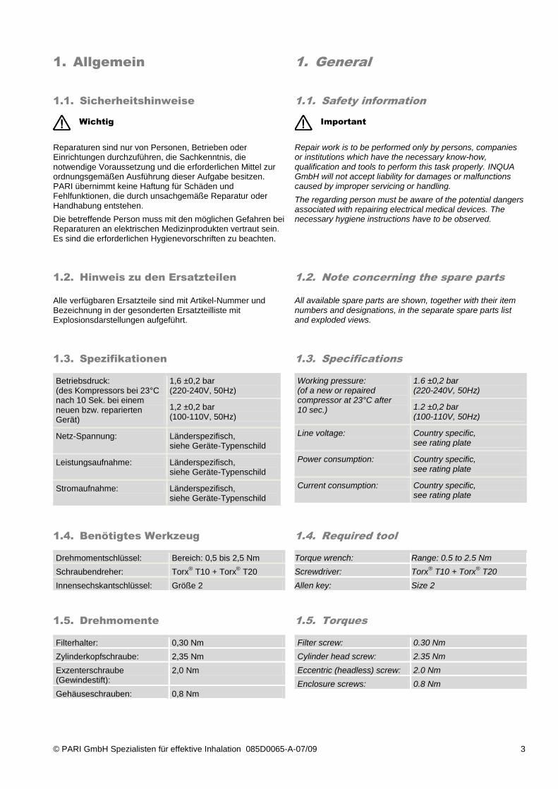
Betriebsdruck: (des Kompressors bei 23°C nach 10 Sek. bei einem neuen bzw. reparierten Gerät)
1,6 ±0,2 bar (220-240V, 50Hz)
1,2 ±0,2 bar (100-110V, 50Hz)
Netz-Spannung: Länderspezifisch, siehe Geräte-Typenschild
Leistungsaufnahme: Länderspezifisch, siehe Geräte-Typenschild
Stromaufnahme: Länderspezifisch, siehe Geräte-Typenschild
Working pressure: (of a new or repaired compressor at 23°C after 10 sec.)
1.6 ±0,2 bar (220-240V, 50Hz)
1.2 ±0,2 bar (100-110V, 50Hz)
Line voltage: Country specific, see rating plate
Power consumption: Country specific, see rating plate
Current consumption: Country specific, see rating plate
1.4. Benötigtes Werkzeug
1.4. Required tool
Drehmomentschlüssel: Bereich: 0,5 bis 2,5 Nm
Schraubendreher: Torx® T10 + Torx
® T20
Innensechskantschlüssel: Größe 2
Torque wrench: Range: 0.5 to 2.5 Nm
Screwdriver: Torx® T10 + Torx
® T20
Allen key: Size 2
1.5. Drehmomente
1.5. Torques
Filterhalter: 0,30 Nm
Zylinderkopfschraube: 2,35 Nm
Exzenterschraube (Gewindestift):
2,0 Nm
Gehäuseschrauben: 0,8 Nm
Filter screw: 0.30 Nm
Cylinder head screw: 2.35 Nm
Eccentric (headless) screw: 2.0 Nm
Enclosure screws: 0.8 Nm
© PARI GmbH Spezialisten für effektive Inhalation 085D0065-A-07/09 4
2. Gehäuse
2. Housing
2.1. Gehäuse öffnen/schließen
2.1. Opening/closing the enclosure
Vor dem Öffnen des Gerätes den Netzstecker ziehen.
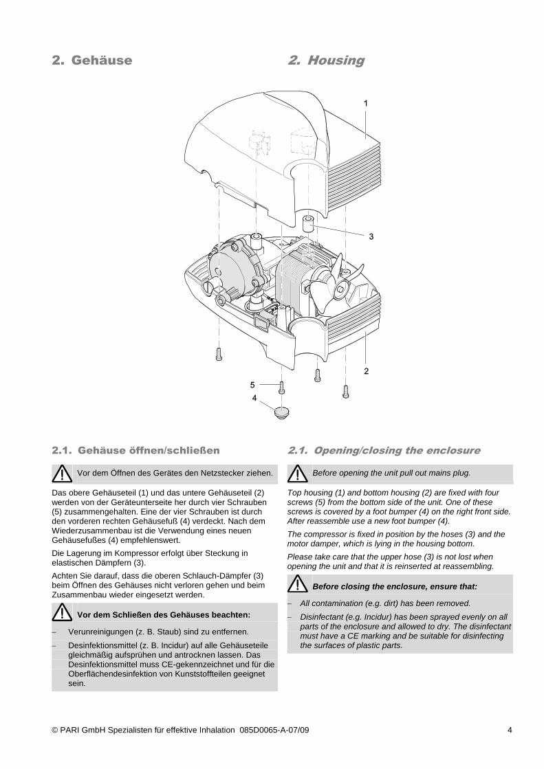
Das obere Gehäuseteil (1) und das untere Gehäuseteil (2) werden von der Geräteunterseite her durch vier Schrauben (5) zusammengehalten. Eine der vier Schrauben ist durch den vorderen rechten Gehäusefuß (4) verdeckt. Nach dem Wiederzusammenbau ist die Verwendung eines neuen Gehäusefußes (4) empfehlenswert.
Die Lagerung im Kompressor erfolgt über Steckung in elastischen Dämpfern (3).
Achten Sie darauf, dass die oberen Schlauch-Dämpfer (3) beim Öffnen des Gehäuses nicht verloren gehen und beim Zusammenbau wieder eingesetzt werden.
Vor dem Schließen des Gehäuses beachten:
Verunreinigungen (z. B. Staub) sind zu entfernen.
Desinfektionsmittel (z. B. Incidur) auf alle Gehäuseteile gleichmäßig aufsprühen und antrocknen lassen. Das Desinfektionsmittel muss CE-gekennzeichnet und für die Oberflächendesinfektion von Kunststoffteilen geeignet sein.
Before opening the unit pull out mains plug.
Top housing (1) and bottom housing (2) are fixed with four screws (5) from the bottom side of the unit. One of these screws is covered by a foot bumper (4) on the right front side. After reassemble use a new foot bumper (4).
The compressor is fixed in position by the hoses (3) and the motor damper, which is lying in the housing bottom.
Please take care that the upper hose (3) is not lost when opening the unit and that it is reinserted at reassembling.
Before closing the enclosure, ensure that:
All contamination (e.g. dirt) has been removed.
Disinfectant (e.g. Incidur) has been sprayed evenly on all parts of the enclosure and allowed to dry. The disinfectant must have a CE marking and be suitable for disinfecting the surfaces of plastic parts.
© PARI GmbH Spezialisten für effektive Inhalation 085D0065-A-07/09 5
3. Baugruppen tauschen
3. Change parts
3.1. Kompressorbaugruppe
3.1. Compressor assy.
Demontage/Montage
Disassembly/Assembly
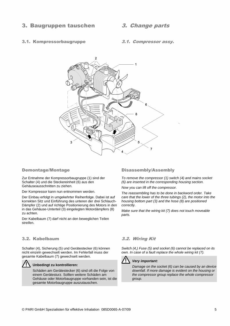
Zur Entnahme der Kompressorbaugruppe (1) sind der Schalter (4) und die Steckereinheit (6) aus den Gehäuseausschnitten zu ziehen.
Der Kompressor kann nun entnommen werden.
Der Einbau erfolgt in umgekehrter Reihenfolge. Dabei ist auf korrekten Sitz und Einführung des unteren der drei Schlauch-Dämpfer (2) und auf richtige Positionierung des Motors in den in das Gehäuse-Unterteil (3) eingelegten Motordämpfers (8) zu achten.
Der Kabelbaum (7) darf nicht an den beweglichen Teilen streifen.
To remove the compressor (1) switch (4) and mains socket (6) are inserted in the corresponding housing section.
Now you can lift off the compressor.
The reassembling has to be done in backword order. Take care that the lower of the three tubings (2), the motor into the housing bottom part (3) and the hose (8) are positioned correctly.
Make sure that the wiring kit (7) does not touch moveable parts.
3.2. Kabelbaum
3.2. Wiring Kit
Schalter (4), Sicherung (5) und Gerätestecker (6) können nicht einzeln gewechselt werden. Im Fehlerfall muss der gesamte Kabelbaum (7) gewechselt werden.
Unbedingt zu kontrollieren:
Schäden am Gerätestecker (6) sind oft die Folge von einem Gerätesturz. Sollten weitere Schäden am Gehäuse oder Motorbaugruppe vorhanden sein, ist die gesamte Motorbaugruppe auszutauschen.
Switch (4,) Fuse (5) and socket (6) cannot be replaced on its own. In case of a fault replace the whole wiring kit (7).
Very important:
Damage on the socket (6) can be caused by an device downfall. If more damage is evident on the housing or the compressor group replace the whole compressor group.
© PARI GmbH Spezialisten für effektive Inhalation 085D0065-A-07/09 6
3.3. Pleuel und Zylinder
3.3. Piston and cylinder
Demontage/Montage
Disassembly/Assembly
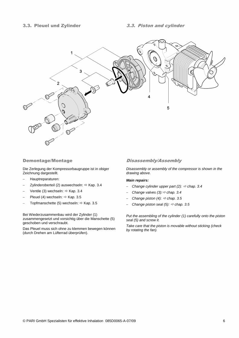
Die Zerlegung der Kompressorbaugruppe ist in obiger Zeichnung dargestellt.
Hauptreparaturen:
Zylinderoberteil (2) auswechseln: Kap. 3.4
Ventile (3) wechseln: Kap. 3.4
Pleuel (4) wechseln: Kap. 3.5
Topfmanschette (5) wechseln: Kap. 3.5
Bei Wiederzusammenbau wird der Zylinder (1) zusammengesetzt und vorsichtig über die Manschette (5) geschoben und verschraubt.
Das Pleuel muss sich ohne zu klemmen bewegen können (durch Drehen am Lüfterrad überprüfen).
Disassembly or assembly of the compressor is shown in the drawing above.
Main repairs:
Change cylinder upper part (2): chap. 3.4
Change valves (3): chap. 3.4
Change piston (4): chap. 3.5
Change piston seal (5): chap. 3.5
Put the assembling of the cylinder (1) carefully onto the piston seal (5) and screw it.
Take care that the piston is movable without sticking (check by rotating the fan).
© PARI GmbH Spezialisten für effektive Inhalation 085D0065-A-07/09 7
3.4. Zylinder-Teile und Ventile
3.4. Cylinder and Valves
Demontage/Montage
Disassembly/Assembly
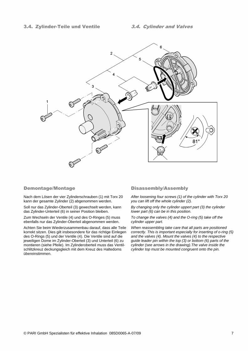
Nach dem Lösen der vier Zylinderschrauben (1) mit Torx 20 kann der gesamte Zylinder (2) abgenommen werden.
Soll nur das Zylinder-Oberteil (3) gewechselt werden, kann das Zylinder-Unterteil (6) in seiner Position bleiben.
Zum Wechseln der Ventile (4) und des O-Ringes (5) muss ebenfalls nur das Zylinder-Oberteil abgenommen werden.
Achten Sie beim Wiederzusammenbau darauf, dass alle Teile korrekt sitzen. Dies gilt insbesondere für das richtige Einlegen des O-Rings (5) und der Ventile (4). Die Ventile sind auf die jeweiligen Dome im Zylinder-Oberteil (3) und Unterteil (6) zu montieren (siehe Pfeile). Im Zylinderoberteil muss das Ventil- schlitzkreuz deckungsgleich mit dem Kreuz des Haltedoms übereinstimmen.
After loosening four screws (1) of the cylinder with Torx 20 you can lift off the whole cylinder (2).
By changing only the cylinder uppert part (3) the cylinder lower part (6) can be in this position.
To change the valves (4) and the O-ring (5) take off the cylinder upper part.
When reassembling take care that all parts are positioned correctly. This is important especially for inserting of o-ring (5) and the valves (4). Mount the valves (4) to the respective guide leader pin within the top (3) or bottom (6) parts of the cylinder (see arrows in the drawing).The valve inside the cylinder top must be mounted congruent onto the pin.
© PARI GmbH Spezialisten für effektive Inhalation 085D0065-A-07/09 8
3.5. Pleuel und Topfmanschette
3.5. Piston and Piston Seal
Demontage/Montage
Disassembly/Assembly
Demontage/ Montage Pleuel
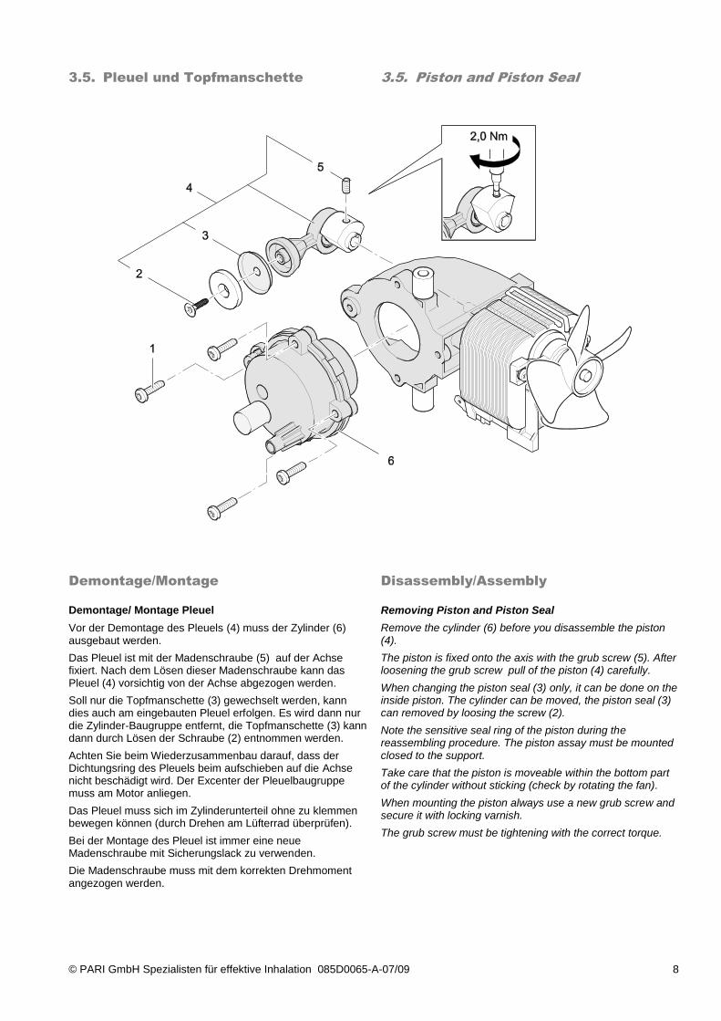
Vor der Demontage des Pleuels (4) muss der Zylinder (6) ausgebaut werden.
Das Pleuel ist mit der Madenschraube (5) auf der Achse fixiert. Nach dem Lösen dieser Madenschraube kann das Pleuel (4) vorsichtig von der Achse abgezogen werden.
Soll nur die Topfmanschette (3) gewechselt werden, kann dies auch am eingebauten Pleuel erfolgen. Es wird dann nur die Zylinder-Baugruppe entfernt, die Topfmanschette (3) kann dann durch Lösen der Schraube (2) entnommen werden.
Achten Sie beim Wiederzusammenbau darauf, dass der Dichtungsring des Pleuels beim aufschieben auf die Achse nicht beschädigt wird. Der Excenter der Pleuelbaugruppe muss am Motor anliegen.
Das Pleuel muss sich im Zylinderunterteil ohne zu klemmen bewegen können (durch Drehen am Lüfterrad überprüfen).
Bei der Montage des Pleuel ist immer eine neue Madenschraube mit Sicherungslack zu verwenden.
Die Madenschraube muss mit dem korrekten Drehmoment angezogen werden.
Removing Piston and Piston Seal
Remove the cylinder (6) before you disassemble the piston (4).
The piston is fixed onto the axis with the grub screw (5). After loosening the grub screw pull of the piston (4) carefully.
When changing the piston seal (3) only, it can be done on the inside piston. The cylinder can be moved, the piston seal (3) can removed by loosing the screw (2).
Note the sensitive seal ring of the piston during the reassembling procedure. The piston assay must be mounted closed to the support.
Take care that the piston is moveable within the bottom part of the cylinder without sticking (check by rotating the fan).
When mounting the piston always use a new grub screw and secure it with locking varnish.
The grub screw must be tightening with the correct torque.
© PARI GmbH Spezialisten für effektive Inhalation 085D0065-A-07/09 9
3.6. Lüfterrad und Lagerbrücke
3.6. Fan and bearing bridge
Demontage
Disassembly
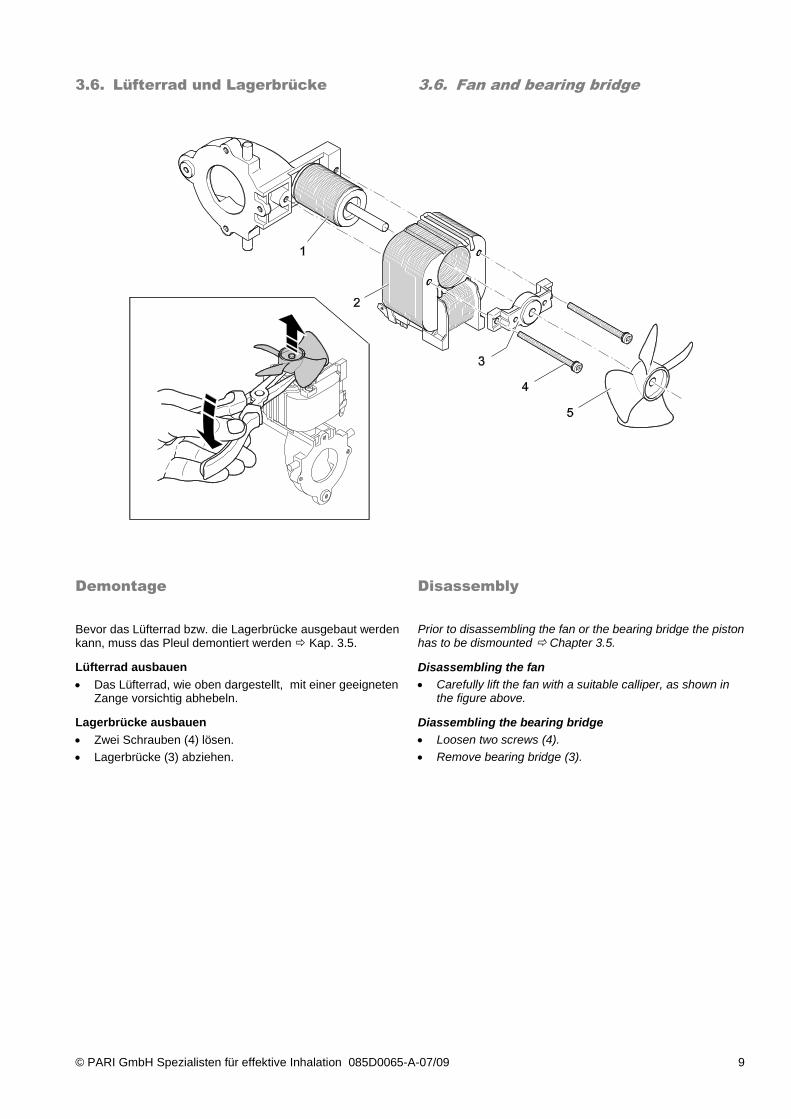
Bevor das Lüfterrad bzw. die Lagerbrücke ausgebaut werden kann, muss das Pleul demontiert werden Kap. 3.5.
Lüfterrad ausbauen
Das Lüfterrad, wie oben dargestellt, mit einer geeigneten Zange vorsichtig abhebeln.
Lagerbrücke ausbauen
Zwei Schrauben (4) lösen.
Lagerbrücke (3) abziehen.
Prior to disassembling the fan or the bearing bridge the piston has to be dismounted Chapter 3.5.
Disassembling the fan
Carefully lift the fan with a suitable calliper, as shown in the figure above.
Diassembling the bearing bridge
Loosen two screws (4).
Remove bearing bridge (3).
© PARI GmbH Spezialisten für effektive Inhalation 085D0065-A-07/09 10
Montage
Assembly
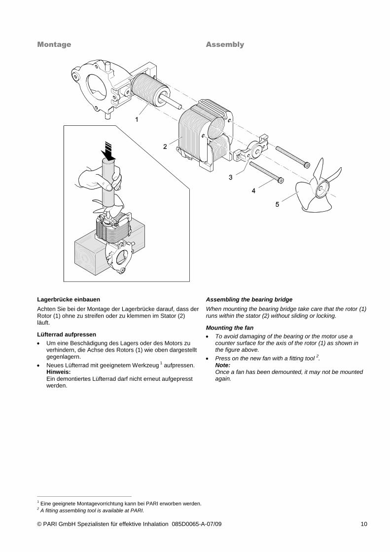
Lagerbrücke einbauen
Achten Sie bei der Montage der Lagerbrücke darauf, dass der Rotor (1) ohne zu streifen oder zu klemmen im Stator (2) läuft.
Lüfterrad aufpressen
Um eine Beschädigung des Lagers oder des Motors zu verhindern, die Achse des Rotors (1) wie oben dargestellt gegenlagern.
Neues Lüfterrad mit geeignetem Werkzeug 1 aufpressen.
Hinweis:
Ein demontiertes Lüfterrad darf nicht erneut aufgepresst werden.
Assembling the bearing bridge
When mounting the bearing bridge take care that the rotor (1) runs within the stator (2) without sliding or locking.
Mounting the fan
To avoid damaging of the bearing or the motor use a counter surface for the axis of the rotor (1) as shown in the figure above.
Press on the new fan with a fitting tool 2.
Note: Once a fan has been demounted, it may not be mounted again.
1 Eine geeignete Montagevorrichtung kann bei PARI erworben werden.
2 A fitting assembling tool is available at PARI.
© PARI GmbH Spezialisten für effektive Inhalation 085D0065-A-07/09 11
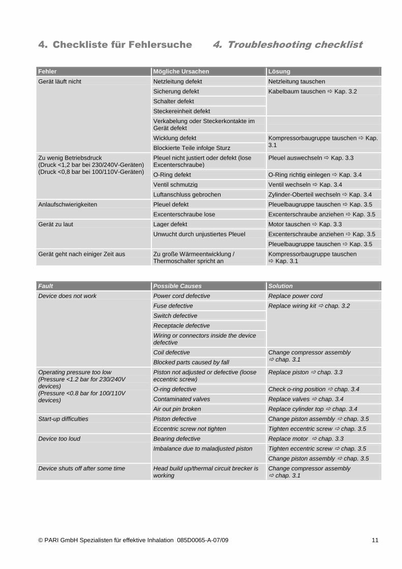
4. Checkliste für Fehlersuche
4. Troubleshooting checklist
Fehler Mögliche Ursachen Lösung
Gerät läuft nicht Netzleitung defekt Netzleitung tauschen
Sicherung defekt Kabelbaum tauschen Kap. 3.2
Schalter defekt
Steckereinheit defekt
Verkabelung oder Steckerkontakte im Gerät defekt
Wicklung defekt Kompressorbaugruppe tauschen Kap. 3.1
Blockierte Teile infolge Sturz
Zu wenig Betriebsdruck (Druck <1,2 bar bei 230/240V-Geräten) (Druck <0,8 bar bei 100/110V-Geräten)
Pleuel nicht justiert oder defekt (lose Excenterschraube)
Pleuel auswechseln Kap. 3.3
O-Ring defekt O-Ring richtig einlegen Kap. 3.4
Ventil schmutzig Ventil wechseln Kap. 3.4
Luftanschluss gebrochen Zylinder-Oberteil wechseln Kap. 3.4
Anlaufschwierigkeiten Pleuel defekt Pleuelbaugruppe tauschen Kap. 3.5
Excenterschraube lose Excenterschraube anziehen Kap. 3.5
Gerät zu laut Lager defekt Motor tauschen Kap. 3.3
Unwucht durch unjustiertes Pleuel Excenterschraube anziehen Kap. 3.5
Pleuelbaugruppe tauschen Kap. 3.5
Gerät geht nach einiger Zeit aus Zu große Wärmeentwicklung / Thermoschalter spricht an
Kompressorbaugruppe tauschen Kap. 3.1
Fault Possible Causes Solution
Device does not work Power cord defective Replace power cord
Fuse defective Replace wiring kit chap. 3.2
Switch defective
Receptacle defective
Wiring or connectors inside the device defective
Coil defective Change compressor assembly chap. 3.1 Blocked parts caused by fall
Operating pressure too low (Pressure <1.2 bar for 230/240V devices) (Pressure <0.8 bar for 100/110V devices)
Piston not adjusted or defective (loose eccentric screw)
Replace piston chap. 3.3
O-ring defective Check o-ring position chap. 3.4
Contaminated valves Replace valves chap. 3.4
Air out pin broken Replace cylinder top chap. 3.4
Start-up difficulties Piston defective Change piston assembly chap. 3.5
Eccentric screw not tighten Tighten eccentric screw chap. 3.5
Device too loud Bearing defective Replace motor chap. 3.3
Imbalance due to maladjusted piston Tighten eccentric screw chap. 3.5
Change piston assembly chap. 3.5
Device shuts off after some time Head build up/thermal circuit brecker is working
Change compressor assembly chap. 3.1
© PARI GmbH Spezialisten für effektive Inhalation 085D0065-A-07/09 12
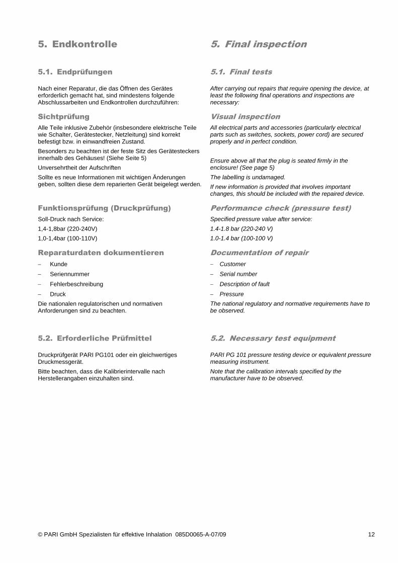
5. Endkontrolle
5. Final inspection
5.1. Endprüfungen
5.1. Final tests
Nach einer Reparatur, die das Öffnen des Gerätes erforderlich gemacht hat, sind mindestens folgende Abschlussarbeiten und Endkontrollen durchzuführen:
After carrying out repairs that require opening the device, at least the following final operations and inspections are necessary:
Sichtprüfung
Alle Teile inklusive Zubehör (insbesondere elektrische Teile wie Schalter, Gerätestecker, Netzleitung) sind korrekt befestigt bzw. in einwandfreien Zustand.
Besonders zu beachten ist der feste Sitz des Gerätesteckers innerhalb des Gehäuses! (Siehe Seite 5)
Unversehrtheit der Aufschriften
Sollte es neue Informationen mit wichtigen Änderungen geben, sollten diese dem reparierten Gerät beigelegt werden.
Visual inspection
All electrical parts and accessories (particularly electrical parts such as switches, sockets, power cord) are secured properly and in perfect condition.
Ensure above all that the plug is seated firmly in the enclosure! (See page 5)
The labelling is undamaged.
If new information is provided that involves important changes, this should be included with the repaired device.
Funktionsprüfung (Druckprüfung)
Soll-Druck nach Service:
1,4-1,8bar (220-240V)
1,0-1,4bar (100-110V)
Performance check (pressure test)
Specified pressure value after service:
1.4-1.8 bar (220-240 V)
1.0-1.4 bar (100-100 V)
Reparaturdaten dokumentieren
Kunde
Seriennummer
Fehlerbeschreibung
Druck
Die nationalen regulatorischen und normativen Anforderungen sind zu beachten.
Documentation of repair
Customer
Serial number
Description of fault
Pressure
The national regulatory and normative requirements have to be observed.
5.2. Erforderliche Prüfmittel
5.2. Necessary test equipment
Druckprüfgerät PARI PG101 oder ein gleichwertiges Druckmessgerät.
Bitte beachten, dass die Kalibrierintervalle nach Herstellerangaben einzuhalten sind.
PARI PG 101 pressure testing device or equivalent pressure measuring instrument.
Note that the calibration intervals specified by the manufacturer have to be observed.
PARI GmbH
Moosstrasse 3 • 82319 Starnberg • Germany
Tel.: +49-(0)81 51-279 0 • Fax: +49-(0)81 51-279 101
E-Mail: [email protected] • www.pari.de