Embed Size (px)
DESCRIPTION
This project investigated the Unreal Development Kit (UDK) and the possibilities it presents for architectural visualization. To create a cost and time efficient solution, a workflow improvement as Maya plugin was created and used to convert architectural data into UDK assets.To use UDK for architectural visualization, the UDK was extended with a modular framework that provides these features: exchangeable environments, time of day visualization, interior lighting, basic architectural shaders, and an interface for user interaction.The system was used to build a demonstration prototype for visualizing a minimalistic house. The protoype was evaluated in a qualitative user study. The results show that users react positively to the visualization and that is has potential for marketing uses.Future projects can build upon the framework to investigate other UDK features, for example, dual-device interactions.
Citation preview
LUDWIG-MAXIMILIANS-UNIVERSITÄT MÜNCHEN
Department “Institut für Informatik”
Lehr- und Forschungseinheit Medieninformatik
Prof. Dr. Heinrich Hußmann
Masterarbeit
Realtime Interactive Architectural Visualization using Unreal Engine 3.5
Neal Bürger
Bearbeitungszeitraum: 01.10.2012 bis 31.03.2013
Betreuer: Prof. Dr. Wolfgang Höhl, Henri Palleis
Verantw. Hochschullehrer: Prof. Dr. Heinrich Hußmann

Realtime Interactive Architectural Visualization using Unreal Engine 3.5
II
Realtime Interactive Architectural Visualization using Unreal Engine 3.5
III
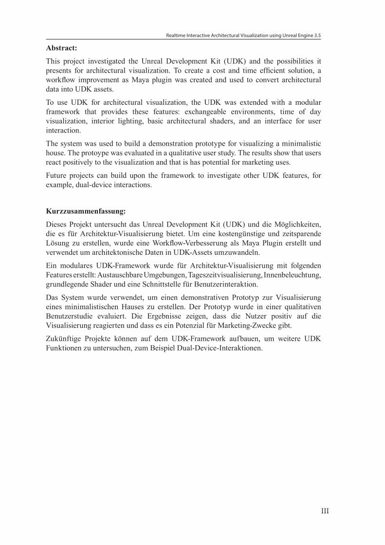
Abstract:
This project investigated the Unreal Development Kit (UDK) and the possibilities it presents for architectural visualization. To create a cost and time efficient solution, a workflow improvement as Maya plugin was created and used to convert architectural data into UDK assets.
To use UDK for architectural visualization, the UDK was extended with a modular framework that provides these features: exchangeable environments, time of day visualization, interior lighting, basic architectural shaders, and an interface for user interaction.
The system was used to build a demonstration prototype for visualizing a minimalistic house. The protoype was evaluated in a qualitative user study. The results show that users react positively to the visualization and that is has potential for marketing uses.
Future projects can build upon the framework to investigate other UDK features, for example, dual-device interactions.
Kurzzusammenfassung:
Dieses Projekt untersucht das Unreal Development Kit (UDK) und die Möglichkeiten, die es für Architektur-Visualisierung bietet. Um eine kostengünstige und zeitsparende Lösung zu erstellen, wurde eine Workflow-Verbesserung als Maya Plugin erstellt und verwendet um architektonische Daten in UDK-Assets umzuwandeln.
Ein modulares UDK-Framework wurde für Architektur-Visualisierung mit folgenden Features erstellt: Austauschbare Umgebungen, Tageszeitvisualisierung, Innenbeleuchtung, grundlegende Shader und eine Schnittstelle für Benutzerinteraktion.
Das System wurde verwendet, um einen demonstrativen Prototyp zur Visualisierung eines minimalistischen Hauses zu erstellen. Der Prototyp wurde in einer qualitativen Benutzerstudie evaluiert. Die Ergebnisse zeigen, dass die Nutzer positiv auf die Visualisierung reagierten und dass es ein Potenzial für Marketing-Zwecke gibt.
Zukünftige Projekte können auf dem UDK-Framework aufbauen, um weitere UDK Funktionen zu untersuchen, zum Beispiel Dual-Device-Interaktionen.

Realtime Interactive Architectural Visualization using Unreal Engine 3.5
IV
Realtime Interactive Architectural Visualization using Unreal Engine 3.5
V
Task Definition for a Masterthesis in Media Informatics
Topic: Realtime Interactive Architectural Visualization using Unreal Engine 3.5
Background:
The cost of many large architectural projects are in the multimillion dollar range [4]. Architects have to persuade the investors that it is the right decision to invest in the project. They have to show that their design is well suited for the project.
Through realtime architectural visualization the investors can explore a building before it has been constructed. Current solutions require expensive specialized hardware and software, and employees operating the system require long and special training. This so far has limited visualization to large projects where the expense could be justified.
As alternative we are exploring game engine technology for architectural visualization. In recent years they have become more sophisticated; the benefits are:
• low cost hardware requirements
• support of a broad range of devices (PC, console, mobile)
• low software licensing costs
This allows visualization to be also used for significantly smaller projects.
General Objectives:
Game engine technology provides a realm of features specifically designed for gaming environments. Some features are not directly required for visualizing architecture, like networking and multi-player features. There are also limitations, like the maximum polygon count of a single object, or maximum number of dynamic lights, that are put in place to ensure optimal performance. The game engine has to be adapted to support architectural visualization features.
The main objective of the thesis is to create a prototype framework for architectural visualization. The prototype should explore the limits of the game engine. 3D artists should be able to create visualizations without specialized training, simply building on basic knowledge of game engine technology.
The 3D artists asset creation workflow has to be complemented with automation tools to effectivly use game engine technology.
The game engine has to be extended with a framework to support the needs for architectural visualization like: time of day simulation, interacting with interior lighting environment, or simulating city life. The framework needs to be implemented in a modular fashion so that parts can be reused or extended.
The final architectural visualization should allow the viewer to freely experience the architecture. A graphical user interface should allow the user to interact with his surroundings.
The prototype should be shown to architectural clients to receive qualitative feedback about the visualization.

Realtime Interactive Architectural Visualization using Unreal Engine 3.5
VI
Tasks:
• Improving the Maya to Unreal Engine workflow with an extension for Maya.
• Create a library of basic Unreal Engine shaders used for architecture with primary focus on optimization for medium end desktop computers.
• Create a custom Unreal Engine Gametype for architectural visualization and apply it to visualize an exemplary architectural structure.
• Support of interactions in the real time environment, interactive lighting, time and day simulation, city environment controls, nature environment controls.
• Design and implementation of the user interface.
• Qualitative evaluation of the prototype
• Giving bi-weekly status updates of the work in progress and a final presentation of the work in the “Disputationsseminar Master”.
• Written thesis

Realtime Interactive Architectural Visualization using Unreal Engine 3.5
VII
„Ich erkläre hiermit, dass ich die vorliegende Arbeit selbstständig angefertigt, alle Zitate als solche kenntlich gemacht, sowie alle benutzten Quellen und Hilfsmittel angegeben habe.“
München, den 28.03.2013 ___________________
Neal Bürger

Realtime Interactive Architectural Visualization using Unreal Engine 3.5
VIII
Realtime Interactive Architectural Visualization using Unreal Engine 3.5
IX
Table of Contents
1. Introduction1.1. Motivation 1
1.2. Goal of the Thesis 1
1.3. Structure of the Thesis 2
2. Related Work2.1. Uses of Architectural Visualization 3
2.2. Real-time Visualization Technology 7
2.3. Utilizing Game Engine Technology for Visualization 10
3. Prototype requirements3.1. Animation Production Pipeline 12
3.2. UDK Production Pipeline 14
3.3. Architectural Visualization Data 17
3.4. Interactive Elements 18
3.5. Technical Specifications 18
4. Maya Plugin UDK-Toolbox4.1. Analyzing the Workflow 19
4.2. Plugin Development 22
4.3. Plugin for Optimized Workflow 22
4.4. Limitations of the Plugin 27
4.5. Optimized Workflow 27
5. UDK Framework for Architectural Visualization5.1. UDK Framework Design 29
5.2. Materials 31
5.3. Lighting 35
5.4. Time of Day Visualization 37
5.5. Exchangeable Environments 40
5.6. Helper Layer 44
5.7. Visualization Menu 44
5.8. UDK Configuration 45
6. Architectural Visualization 6.1. The XY-house (RS+ Robert Skitek) 47
Realtime Interactive Architectural Visualization using Unreal Engine 3.5
X
6.2. Interior Lighting 48
6.3. Frame Rate 49
7. User Study7.1. Conditions 50
7.2. Tasks 50
7.3. Study Design 50
7.4. Participants 51
7.5. Qualitative Feedback 51
7.6. Observations 56
7.7. Discussion 57
8. Summary8.1. Comments on the Lighting System 58
8.2. Future Work 59
9. References
10. Contents of attached CD
11. Appendix11.1. Code UDK ToolBox 65
11.2. Example T3D File 78
11.3. ActionScript Code 78

Realtime Interactive Architectural Visualization using Unreal Engine 3.5
XI
Realtime Interactive Architectural Visualization using Unreal Engine 3.5
1
1. IntroductionIn the architectural business, visual presentation have always played a major role. Often these projects are in the multi-million dollar range [4]. Architects have to convince their clients that their solution is the best one. Realtime visualization allows both architects and clients to discuss all aspects of the proposed design.
1.1. MotivationMany smaller 3D production studios focus entirely on animations and rendering of 3D still images. Creating an interactive 3D environment is complex and more expensive than traditional animation. The studio must factor in the cost of creating (or licensing) a real-time 3D engine solution and the need of a large team size. In addition, the 3D artists have to be trained to create usable 3D assets as required by the 3D engine as well as operating the software. On top of that, licensed 3D engines have to be modified to suit the individual use case, and in most cases, they only run on specialized hardware.
In the last few years, many game engines have become available for free (or very low licensing costs) [32]. “Computer game technology is accessible, modifiable, and can be utilized for new uses beyond the typical gaming application” [36]. However, the entry barrier to use game engine technology is very high as a variety of technologies are unified in a game engine.
The core functionality of a game engine typically includes a 2D or 3D rendering solution. The rendering capabilities have increased drastically over the last few years to a point where near photo-realistic renderings can be made in realtime. Beside the benefit of having low licensing costs, there are minimal hardware requirements. When integrating game engine technology into a 3D animation workflow, it enables fast pre-visualization of complex animation [40].
The 3D game engine technology can be applied to architectural visualization. Usually, visualization focuses on the exterior or the interior of a building, and the viewer is limited by still images or animations to view the building at a specific angle and at a specific time of day. By creating an interactive visualization, both visualization types can be merged into a single experience. The architecture is experienced by walking through the rooms, by dynamically simulating various times of day, room layouts, or weather conditions.
Game development uses a large team size to create a game. However, architectural visualization is a rather specific application and it is feasible to develop a system that can be handled by a small team or single person to create visualizations in a short time frame.
1.2. Goal of the ThesisThe goal of this thesis is to provide a path to create an interactive architectural visualization. The visualization should be able to be viewed using a typical desktop environment. The prototype should demonstrate the current capabilities and explore limits of game engines for architectural visualization.
Another goal of the thesis is to reduce the time needed to create such types of visualizations. This can be accomplished by creating a modular system that can easily be expanded for architectural projects, reducing the manpower needed to create such visualizations.
Realtime Interactive Architectural Visualization using Unreal Engine 3.5
2
The system should improve parts of the asset creation pipeline, making it easier for architects or 3D artists to create assets for the game engine.
The completed visualization concept should be evaluated with regard to user experience for interacting with the system, the lighting visualization, and for marketing purposes.
1.3. Structure of the ThesisChapter 2 covers the related work in the areas of architectural visualization, realtime rendering solutions, and use of game technology for visualization.
Chapter 3 covers the animation pipeline and the UDK production pipeline. In addition, the available data and interaction possibilites are discussed that define the prototype requirements
In Chapter 4 we introduce the FBX workflow that leads to the requirements for writing a plugin, and the features we provide with the plugin. We will present the created plugin, optimized workflow, and discuss its limitations.
In Chapter 5 we discuss how we extended the Unreal Engine to serve as a framework for architectural visualization.
Chapter 6 covers the creation of an architectural visualization prototype using the framework.
Chapter 7 covers the conducted qualitative user study to figure out how potential users would interact with the system. In the first part, the conditions, tasks, study design, and participants are described. In the second part, qualitative feedback and observations are presented. The last part is a discussion of the outcome.
In Chapter 8 the results of the thesis are discussed and an outlook to further work is presented.
Realtime Interactive Architectural Visualization using Unreal Engine 3.5
3
2. Related WorkThis chapter covers the related work in the areas of architectural visualization, realtime rendering solutions, and use of game technology for visualization.
2.1. Uses of Architectural VisualizationArchitects use various abstract visualizations as planning tools during the design process. They take into account how the city scape will be changed by individual buildings, as well as how the interior of buildings are designed. The main focus of these visualizations is abstract room planning, lighting planning, and volume blocking. People commonly associate architectural visualization with photo-realistic “walkthrough” animations or with still shots [41].
2.1.1. Communication tool
One of the main goals of architectural visualization is to simplify the communication between architects and clients. Architects work with multiple two-dimensional technical drawing information about the building that is stored in multiple types of data sheets. Clients usually have no deeper knowledge about the subject matter. They have to learn skills to interpret the architectural designs.
No matter how much the client learns, his communication will not be on the same level as the architect’s. Lexical communication is too inaccurate to communicate clearly spactial relations, and traditional visual communication with technical drawings requires mental imagery generation on the client side. However, mental imagery generation of the information receiver should be kept at its minimum for the purpose of leaving more capacity for the more important spatial reasoning process [18]. Additionally, communication can fail because client and architect are creating different mental imagery [18].
Using three-dimensional visualization compared to technical drawings minimizes mental imagery generation on the client side, while reducing the information load on the working memory. Additionally abstract data that is included in the technical drawings can be integrated into the visualization, reducing the analyzing process connected to the abstracted information. This reduces miscommunication about spacial relations [18].
2.1.2. Marketing tool
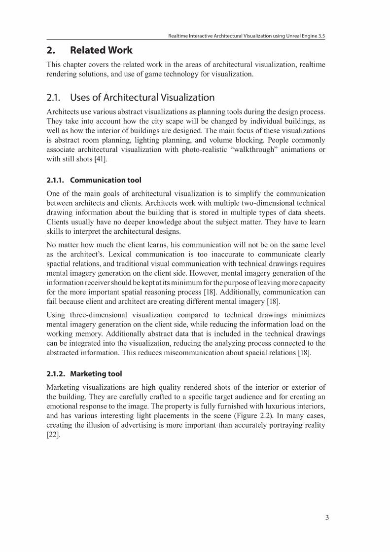
Marketing visualizations are high quality rendered shots of the interior or exterior of the building. They are carefully crafted to a specific target audience and for creating an emotional response to the image. The property is fully furnished with luxurious interiors, and has various interesting light placements in the scene (Figure 2.2). In many cases, creating the illusion of advertising is more important than accurately portraying reality [22].
Realtime Interactive Architectural Visualization using Unreal Engine 3.5
4
Figure 2.1.: Rodrigo Zacharias, Decorated Suite [60]
Visualization can also take the form of animation. The architect defines a path through the building to guide the camera animation. Overall, this type of visualization is more costly than single frame renders, because more frames have to be rendered, a visually suitable path has to be chosen, and usually ambient music is added to the animation [41]. The benefit of such animation is that a full story about the architectural project can be told. However, the viewer only sees, what the architect has chosen, but may not see all aspects of the building.
Since 1994 it was envisioned that real estate brokers could allow clients to walk-through potential properties on their computer [15]. The idea was that the client enters the broker’s office and the broker shows multiple properties to the client on his computer. Only if the client finds a potential property, the broker takes the client to the property.
When utilizing virtual reality (VR), the client can move around freely in the environment, and explore any aspect of the building. With this freedom the client develops his own viewing experience without being influenced by the marketing department.
The virtual environment experience can be further enhanced by utilizing VR-Helmets, a helmet with integrated screens and motion sensors, or VR-Cave environments, a room with projections on every wall for visualization.
2.1.3. City Scape Visualization
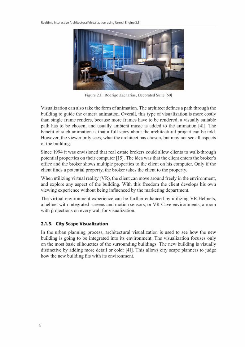
In the urban planning process, architectural visualization is used to see how the new building is going to be integrated into its environment. The visualization focuses only on the most basic silhouettes of the surrounding buildings. The new building is visually distinctive by adding more detail or color [41]. This allows city scape planners to judge how the new building fits with its environment.
Realtime Interactive Architectural Visualization using Unreal Engine 3.5
5
Figure 2.2.: Berlin, Bode-Museum planning [55]
To analyze potential hazards, the city scape visualization can be extended with crowd simulation software. The architectural visualization can be used to figure out how the new building effects, for example, emergency situations.
A crowd simulation creates a crowd made up of entities that represent people and simulates an emergency event. The crowd simulation uses a psychological model that is derived from analysis from crowds in the real world. Additionally, entities like firefighters, police or ambulance can be added to the simulation. The city scape planners can then visually identify potential problems where the flow of the crowd results in bottlenecks or forms gridlocks. This information is valuable because in this phase of planning it is easy to redesign the building to remove potential hazards.
Crowd simulation models are very complex and at the same time every crowd is made up of different people that have unpredictable reactions, making the accuracy of these models debatable. However, it is difficult to conduct studies of real life danger situations and the results of the studies do not provide conclusive results. This means that even the most advanced crowd prediction model has a limited validity of their results and should be used only as a guideline.
2.1.4. Sustainable Architecture Visualziaton
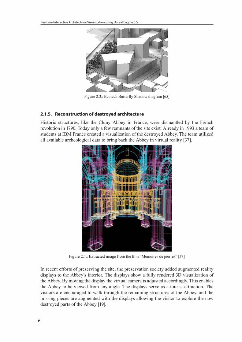
Architects use visualization as planning tool. An interesting example is designing sustainable structures. One tool to analyse strutures is Autodesk Ecotech [12]. A few key features are: analysing thermal performance, solar radiation, photovoltaic collection, and day lighting [13]. For each of these features a physical model and unique visualization technique is used.
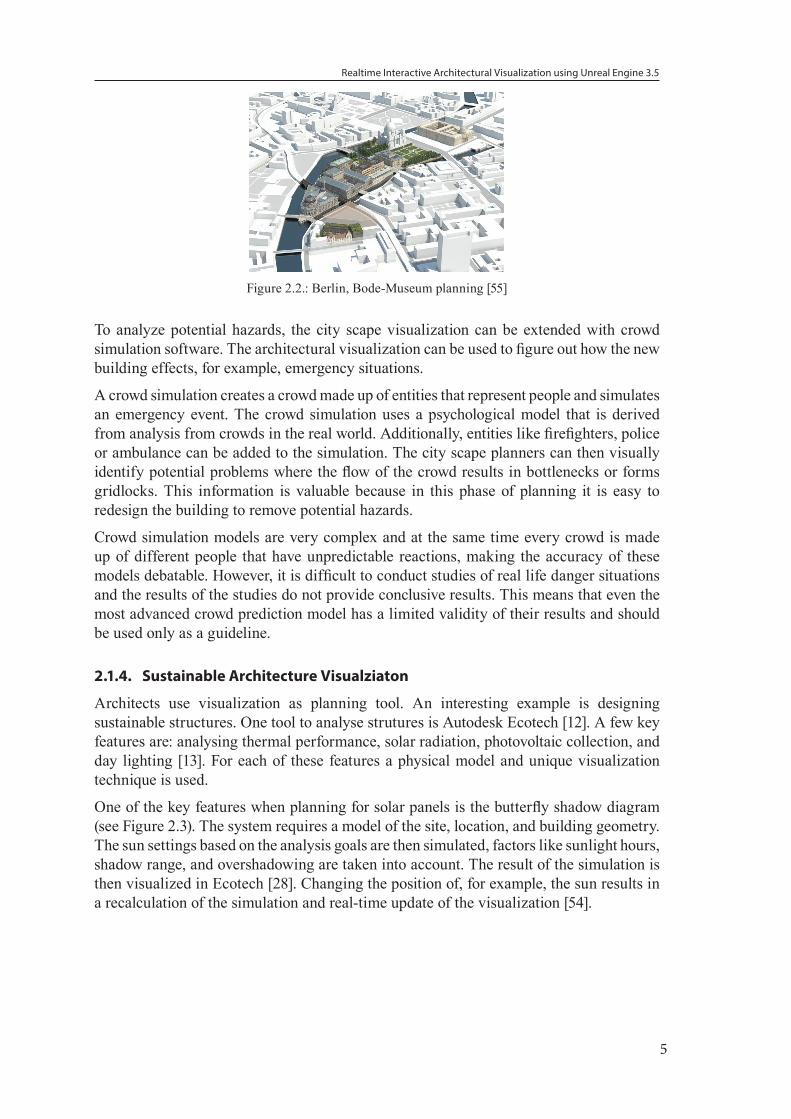
One of the key features when planning for solar panels is the butterfly shadow diagram (see Figure 2.3). The system requires a model of the site, location, and building geometry. The sun settings based on the analysis goals are then simulated, factors like sunlight hours, shadow range, and overshadowing are taken into account. The result of the simulation is then visualized in Ecotech [28]. Changing the position of, for example, the sun results in a recalculation of the simulation and real-time update of the visualization [54].
Realtime Interactive Architectural Visualization using Unreal Engine 3.5
6
Figure 2.3.: Ecotech Butterfly Shadow diagram [65]
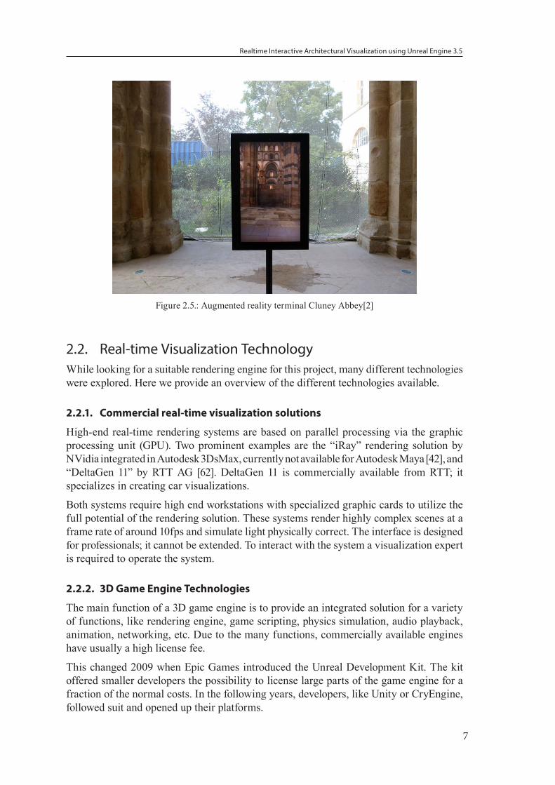
2.1.5. Reconstruction of destroyed architecture
Historic structures, like the Cluny Abbey in France, were dismantled by the French revolution in 1790. Today only a few remnants of the site exist. Already in 1993 a team of students at IBM France created a visualization of the destroyed Abbey. The team utilized all available archeological data to bring back the Abbey in virtual reality [37].
Figure 2.4.: Extracted image from the film “Memoires de pierres” [37]
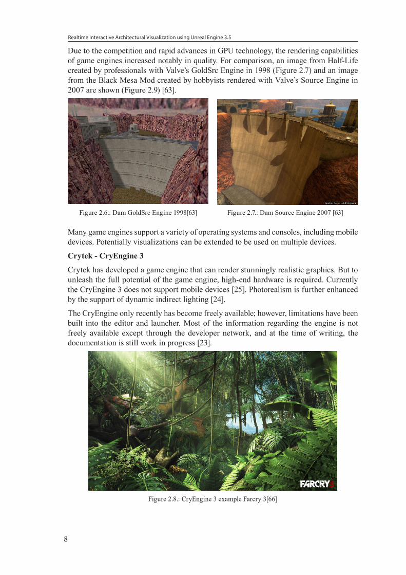
In recent efforts of preserving the site, the preservation society added augmented reality displays to the Abbey’s interior. The displays show a fully rendered 3D visualization of the Abbey. By moving the display the virtual camera is adjusted accordingly. This enables the Abbey to be viewed from any angle. The displays serve as a tourist attraction. The visitors are encouraged to walk through the remaining structures of the Abbey, and the missing pieces are augmented with the displays allowing the visitor to explore the now destroyed parts of the Abbey [19].
Realtime Interactive Architectural Visualization using Unreal Engine 3.5
7
Figure 2.5.: Augmented reality terminal Cluney Abbey[2]
2.2. Real-time Visualization TechnologyWhile looking for a suitable rendering engine for this project, many different technologies were explored. Here we provide an overview of the different technologies available.
2.2.1. Commercial real-time visualization solutions
High-end real-time rendering systems are based on parallel processing via the graphic processing unit (GPU). Two prominent examples are the “iRay” rendering solution by NVidia integrated in Autodesk 3DsMax, currently not available for Autodesk Maya [42], and “DeltaGen 11” by RTT AG [62]. DeltaGen 11 is commercially available from RTT; it specializes in creating car visualizations.
Both systems require high end workstations with specialized graphic cards to utilize the full potential of the rendering solution. These systems render highly complex scenes at a frame rate of around 10fps and simulate light physically correct. The interface is designed for professionals; it cannot be extended. To interact with the system a visualization expert is required to operate the system.
2.2.2. 3D Game Engine Technologies
The main function of a 3D game engine is to provide an integrated solution for a variety of functions, like rendering engine, game scripting, physics simulation, audio playback, animation, networking, etc. Due to the many functions, commercially available engines have usually a high license fee.
This changed 2009 when Epic Games introduced the Unreal Development Kit. The kit offered smaller developers the possibility to license large parts of the game engine for a fraction of the normal costs. In the following years, developers, like Unity or CryEngine, followed suit and opened up their platforms.
Realtime Interactive Architectural Visualization using Unreal Engine 3.5
8
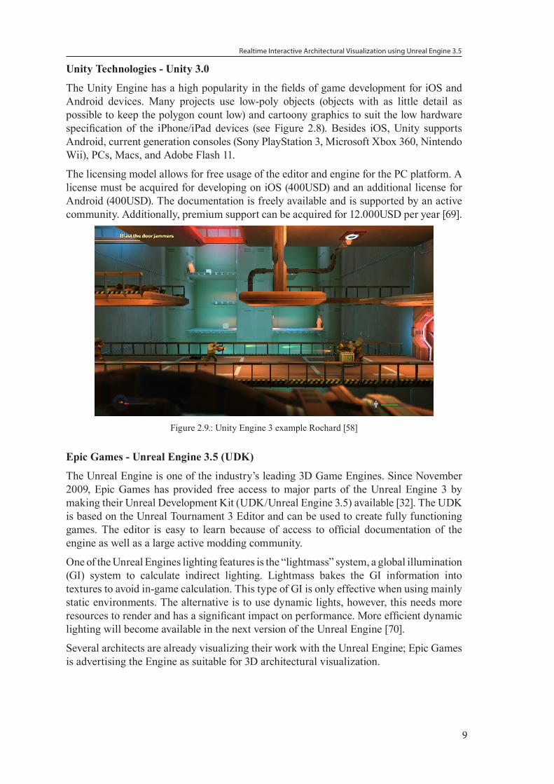
Due to the competition and rapid advances in GPU technology, the rendering capabilities of game engines increased notably in quality. For comparison, an image from Half-Life created by professionals with Valve’s GoldSrc Engine in 1998 (Figure 2.7) and an image from the Black Mesa Mod created by hobbyists rendered with Valve’s Source Engine in 2007 are shown (Figure 2.9) [63].
Figure 2.6.: Dam GoldSrc Engine 1998[63]
Figure 2.7.: Dam Source Engine 2007 [63]
Many game engines support a variety of operating systems and consoles, including mobile devices. Potentially visualizations can be extended to be used on multiple devices.
Crytek - CryEngine 3
Crytek has developed a game engine that can render stunningly realistic graphics. But to unleash the full potential of the game engine, high-end hardware is required. Currently the CryEngine 3 does not support mobile devices [25]. Photorealism is further enhanced by the support of dynamic indirect lighting [24].
The CryEngine only recently has become freely available; however, limitations have been built into the editor and launcher. Most of the information regarding the engine is not freely available except through the developer network, and at the time of writing, the documentation is still work in progress [23].
Figure 2.8.: CryEngine 3 example Farcry 3[66]
Realtime Interactive Architectural Visualization using Unreal Engine 3.5
9
Unity Technologies - Unity 3.0
The Unity Engine has a high popularity in the fields of game development for iOS and Android devices. Many projects use low-poly objects (objects with as little detail as possible to keep the polygon count low) and cartoony graphics to suit the low hardware specification of the iPhone/iPad devices (see Figure 2.8). Besides iOS, Unity supports Android, current generation consoles (Sony PlayStation 3, Microsoft Xbox 360, Nintendo Wii), PCs, Macs, and Adobe Flash 11.
The licensing model allows for free usage of the editor and engine for the PC platform. A license must be acquired for developing on iOS (400USD) and an additional license for Android (400USD). The documentation is freely available and is supported by an active community. Additionally, premium support can be acquired for 12.000USD per year [69].
Figure 2.9.: Unity Engine 3 example Rochard [58]
Epic Games - Unreal Engine 3.5 (UDK)
The Unreal Engine is one of the industry’s leading 3D Game Engines. Since November 2009, Epic Games has provided free access to major parts of the Unreal Engine 3 by making their Unreal Development Kit (UDK/Unreal Engine 3.5) available [32]. The UDK is based on the Unreal Tournament 3 Editor and can be used to create fully functioning games. The editor is easy to learn because of access to official documentation of the engine as well as a large active modding community.
One of the Unreal Engines lighting features is the “lightmass” system, a global illumination (GI) system to calculate indirect lighting. Lightmass bakes the GI information into textures to avoid in-game calculation. This type of GI is only effective when using mainly static environments. The alternative is to use dynamic lights, however, this needs more resources to render and has a significant impact on performance. More efficient dynamic lighting will become available in the next version of the Unreal Engine [70].
Several architects are already visualizing their work with the Unreal Engine; Epic Games is advertising the Engine as suitable for 3D architectural visualization.

Realtime Interactive Architectural Visualization using Unreal Engine 3.5
10
Figure 2.10.: Unreal Engine 3 Samaritan Demo[39]
2.2.3. Comparison
Current commercial real-time rendering solutions (iRay, Deltagen 11) do not provide capabilities to build custom user interfaces. On the other hand, game engine technology can be extended with a customized user interface for architectural visualization.
To create a framework that supports a wide range of features, we compared the most popular technologies with emphasis on photorealism, documentation, support of mobile devices, and licensing costs.
Unity 3 CryEngine 3 UDK Photorealism Low High MediumDocumentation Medium Low HighMobile devices Yes No YesLicensing iOS 400USD Free Free
We decided not to use the Unity Engine because of the additional licensing costs for iOS development.
When comparing UDK to the CryEngine, the CryEngine currently has superior render qualities due to the support of dynamic lighting. It is not known, if the CryEngine is going to be available on the iOS/Android systems.
For our research, the Unreal Engine seems to be the best match due to the high compatibility with other operating system platforms. It is also a great benefit to have an active community and extensive documentation of the engine. In addition, the upcoming Unreal Engine 4 will address the currently lacking features in the lighting engine [29].
2.3. Utilizing Game Engine Technology for Visualization Prior to 2009, research teams had to modify video games to gain access to the rendering engine to conduct research.
Realtime Interactive Architectural Visualization using Unreal Engine 3.5
11
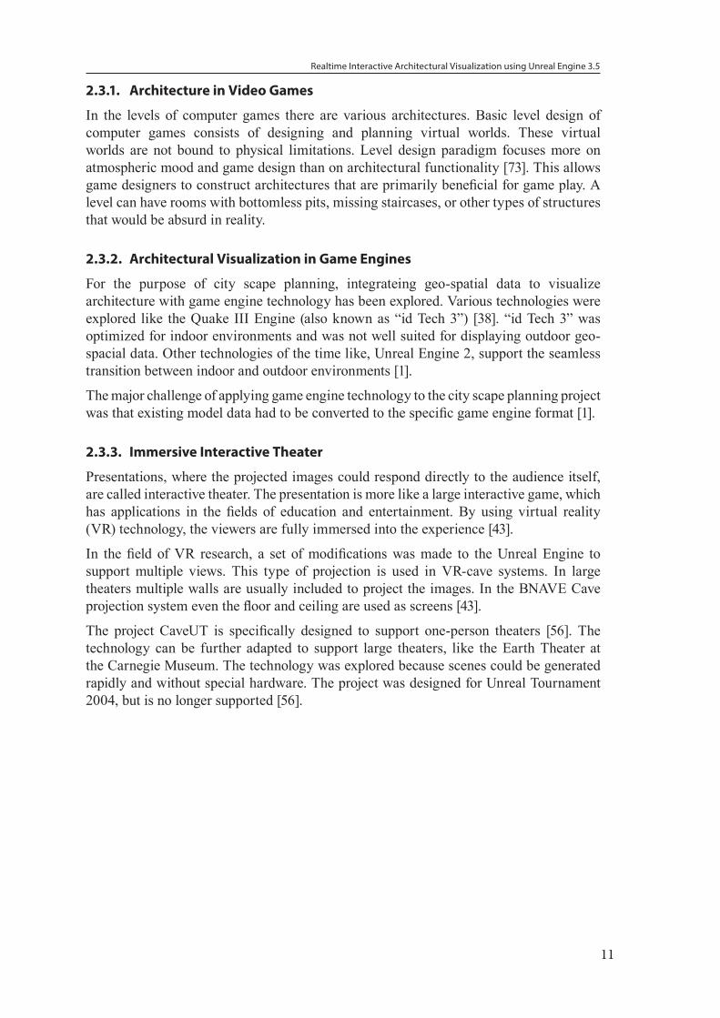
2.3.1. Architecture in Video Games
In the levels of computer games there are various architectures. Basic level design of computer games consists of designing and planning virtual worlds. These virtual worlds are not bound to physical limitations. Level design paradigm focuses more on atmospheric mood and game design than on architectural functionality [73]. This allows game designers to construct architectures that are primarily beneficial for game play. A level can have rooms with bottomless pits, missing staircases, or other types of structures that would be absurd in reality.
2.3.2. Architectural Visualization in Game Engines
For the purpose of city scape planning, integrateing geo-spatial data to visualize architecture with game engine technology has been explored. Various technologies were explored like the Quake III Engine (also known as “id Tech 3”) [38]. “id Tech 3” was optimized for indoor environments and was not well suited for displaying outdoor geo-spacial data. Other technologies of the time like, Unreal Engine 2, support the seamless transition between indoor and outdoor environments [1].
The major challenge of applying game engine technology to the city scape planning project was that existing model data had to be converted to the specific game engine format [1].
2.3.3. Immersive Interactive Theater
Presentations, where the projected images could respond directly to the audience itself, are called interactive theater. The presentation is more like a large interactive game, which has applications in the fields of education and entertainment. By using virtual reality (VR) technology, the viewers are fully immersed into the experience [43].
In the field of VR research, a set of modifications was made to the Unreal Engine to support multiple views. This type of projection is used in VR-cave systems. In large theaters multiple walls are usually included to project the images. In the BNAVE Cave projection system even the floor and ceiling are used as screens [43].
The project CaveUT is specifically designed to support one-person theaters [56]. The technology can be further adapted to support large theaters, like the Earth Theater at the Carnegie Museum. The technology was explored because scenes could be generated rapidly and without special hardware. The project was designed for Unreal Tournament 2004, but is no longer supported [56].
Realtime Interactive Architectural Visualization using Unreal Engine 3.5
12
3. Prototype requirementsIn this chapter the general requirements of the prototype are analyzed and defined.
It covers the topics animation production pipeline and Unreal Engine production pipeline. It continues with data available for visualization and interaction possibilites. In the last part we specify the technical requirements.
3.1. Animation Production PipelineWe are going to look at the general process how 3D visualizations are produced by studio environments. This same process is applied to architectural visualization. In a typical studio a team of specialized artists and technical directors (TD) are available for working on the project [21]. TDs are artists that specialize in the field of lighting, rendering, rigging, and other areas.
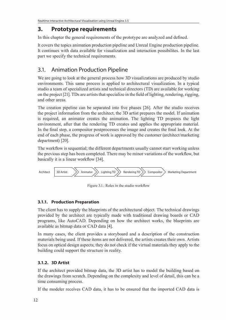
The creation pipeline can be separated into five phases [26]. After the studio receives the project information from the architect, the 3D artist prepares the model. If animation is required, an animator creates the animation. The lighting TD prepares the light environment, after that the rendering TD creates and applies the appropriate material. In the final step, a compositor postprocesses the image and creates the final look. At the end of each phase, the progress of work is approved by the customer (architect/marketing department) [20].
The workflow is sequential; the different departments usually cannot start working unless the previous step has been completed. There may be minor variations of the workflow, but basically it is a linear workflow [34].
Architect 3D Artist Animator Lighting TD CompositorRendering TD Marketing Department
Figure 3.1.: Roles in the studio workflow
3.1.1. Production Preparation
The client has to supply the blueprints of the architectural object. The technical drawings provided by the architect are typically made with traditional drawing boards or CAD programs, like AutoCAD. Depending on how the architect works, the blueprints are available as bitmap data or CAD data [4].
In many cases, the client provides a storyboard and a description of the construction materials being used. If these items are not delivered, the artists creates their own. Artists focus on optical design aspects; they do not check if the virtual materials they apply to the building could support the structure in reality.
3.1.2. 3D Artist
If the architect provided bitmap data, the 3D artist has to model the building based on the drawings from scratch. Depending on the complexity and level of detail, this can be a time consuming process.
If the modeler receives CAD data, it has to be ensured that the imported CAD data is
Realtime Interactive Architectural Visualization using Unreal Engine 3.5
13
suitable for visualization. A typical problem is overlapping geometry. This happens when the same geometry is exported multiple times. An example is a double-sided window. Another common problem is that unneeded geometry artificats may be imported that require correction. These issues have to be manually corrected by the artist.
The CAD data is represented in 3D authoring software as NURBS (non-uniform rational basis spline) objects. At the time of rendering, the objects are automatically converted into polygonal objects. Common problem when using NURBS are visible seams between objects resulting in holes in the geometry [27]. The permanent way to eliminate all seams is to convert these objects into polygon objects and stitch the geometry. This ensures that no errors occur during the render process.
When the artist has completed his work, the completed scene is passed to the next production step.
3.1.3. Animation
The typical animation for architecture is a fly-through of the model. The animator creates a virtual camera, defines a movement path, and animates the camera movement.
If the animation is more complex, for example, like opening of blinds, the animator has to create a simple animation rig to control the blinds and then create the animation. For more complex animations an additional professional Rigging TD is needed.
The animation is added to the scene as provided by the 3D artist and then passed to the next production step.
3.1.4. Lighting and Rendering
To properly light a scene all camera positions have to be defined beforehand. Virtual lights are then added to the scene to create a specific mood. Architectural lighting uses warm evening lighting to create the impression of a pleasant ambiance, or nighttime lighting with many different lightsources to make it visually interesting [74].
Depending on the realism of the scene, light probes of real lights are made and integrated into the scene. In practice, the Lighting TD and Rendering TD work closely together to create a realistic rendering.
The Rendering TD has to ensure that the scene is optimized for the render process. He has to select and modify the materials so that they are effective and time efficient for rendering. This means, for example, that objects that are in the background and barely visible do not have very complex shaders.
When the scene is finalized, the render process creates for every frame of the animation an image. This image sequence is then passed to the next production step.
3.1.5. Post processing
The Compositor uses tools like “The Foundry - Nuke” [64] or “Adobe - AfterEffects” [6] to enhance the visual quality of the images. The sequence is color graded to create a specific mood. To further enhance the image, visual effects, like “bloom” or “lens flares”, are added.
Depth of field is a common tool to emphasize photorealism. While 3D render engines
Realtime Interactive Architectural Visualization using Unreal Engine 3.5
14
have the capability to render “depth of field”, in most cases, it is more efficient to add blurring in the post processing step.
As final step, the Compositor converts the image sequence into a movie clip.
3.2. UDK Production PipelineThe UDK production pipeline requires steps simuliar to the animation pipeline. In addition to the professionals required for creating an animation, programmers are needed to configure the game engine.
3.2.1. Overview
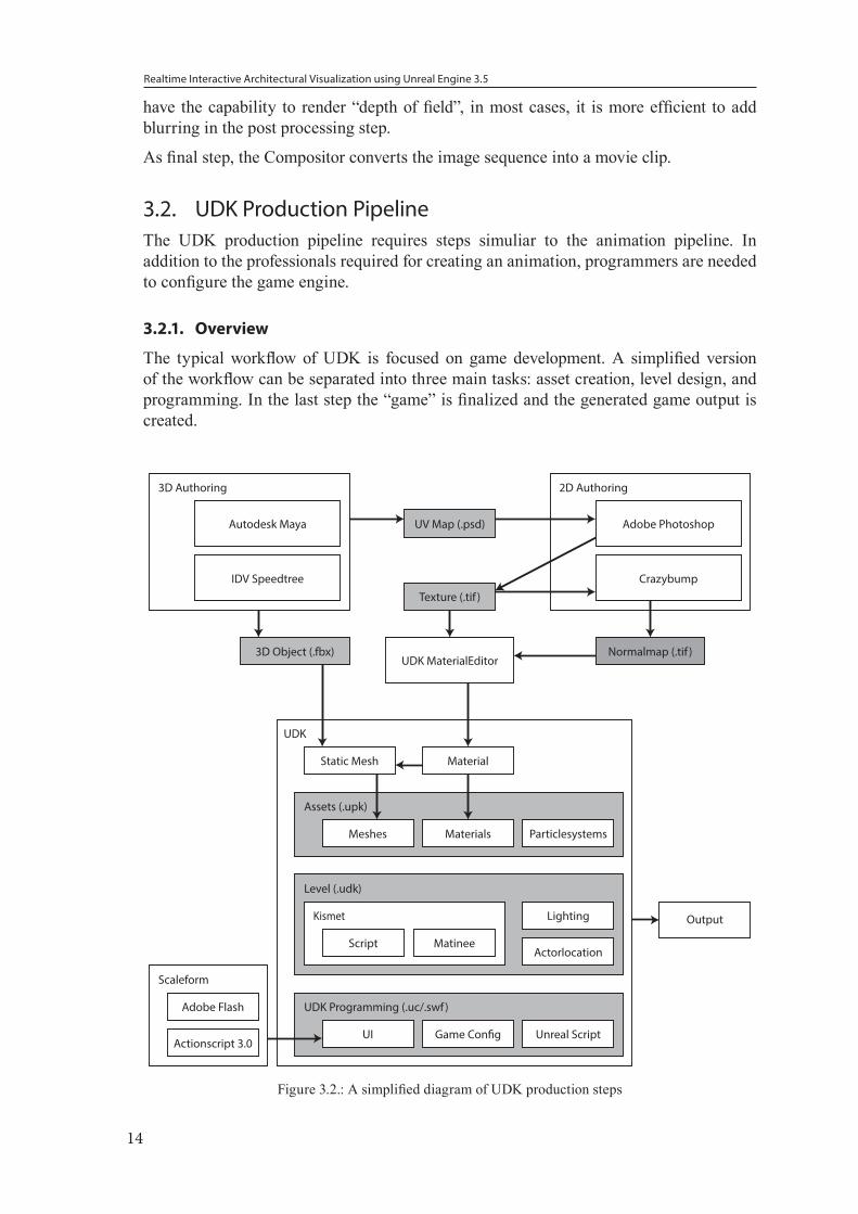
The typical workflow of UDK is focused on game development. A simplified version of the workflow can be separated into three main tasks: asset creation, level design, and programming. In the last step the “game” is finalized and the generated game output is created.
Materials
Material
Output
Static Mesh
UDK MaterialEditor
Meshes
Actorlocation
LightingKismet
Script Matinee
Particlesystems
UDK
Assets (.upk)
Level (.udk)
Autodesk Maya UV Map (.psd)
Texture (.tif )
Normalmap (.tif )
IDV Speedtree
3D Object (.fbx)
3D Authoring
Adobe Flash
Actionscript 3.0
Scaleform
UI Unreal ScriptGame Con�g
UDK Programming (.uc/.swf)
Adobe Photoshop
Crazybump
2D Authoring
Figure 3.2.: A simplified diagram of UDK production steps
Realtime Interactive Architectural Visualization using Unreal Engine 3.5
15
3.2.2. Asset Creation
There are three main types of assets required for creating a basic UDK Game:
• 3D assets, containing geometry
• 2D textures
• Flash files (.swf), containing the graphical user interface
Assets that are created in external programes are imported and managed in the UDK Editor. Each of these asset types have their own workflow.
3D Assets
UDK supports two main types of geometry: binary space partitioning (BSP) and static meshes. BSP geometry is directly created in the Unreal Editor, but is discouraged to use due to potential performance issues.
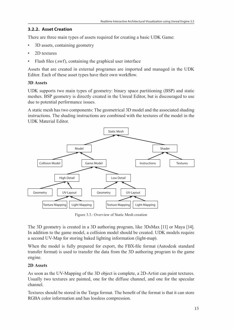
A static mesh has two components: The geometrical 3D model and the associated shading instructions. The shading instructions are combined with the textures of the model in the UDK Material Editor.
Static Mesh
Model Shader
Collision Model Game Model
High Detail Low Detail
Geometry UV-Layout
Texture Mapping Light Mapping
Instructions Textures
Geometry UV-Layout
Texture Mapping Light Mapping
Figure 3.3.: Overview of Static Mesh creation
The 3D geometry is created in a 3D authoring program, like 3DsMax [11] or Maya [14]. In addition to the game model, a collision model should be created. UDK models require a second UV-Map for storing baked lighting information (light-map).
When the model is fully prepared for export, the FBX-file format (Autodesk standard transfer format) is used to transfer the data from the 3D authoring program to the game engine.
2D Assets
As soon as the UV-Mapping of the 3D object is complete, a 2D-Artist can paint textures. Usually two textures are painted, one for the diffuse channel, and one for the specular channel.
Textures should be stored in the Targa format. The benefit of the format is that it can store RGBA color information and has lossless compression.
Realtime Interactive Architectural Visualization using Unreal Engine 3.5
16
Flash Assets
Scaleform is a middleware solution to allow the playback of Flash files in a 3D environment. These Flash elements are used to create a graphical user interface for the game environment as well as the menu. Scaleform implements a subset of Actionscript 3.0 commands, allowing dynamic functionality.
These assets can be created with Adobe Flash [7] or any alternative program, as UDK requires the compiled flash format (.swf).
Other Assets
UDK also provides the possibility to import other types of file formats, for example, video files (Blink Format) or tree models (SpeedTree files).
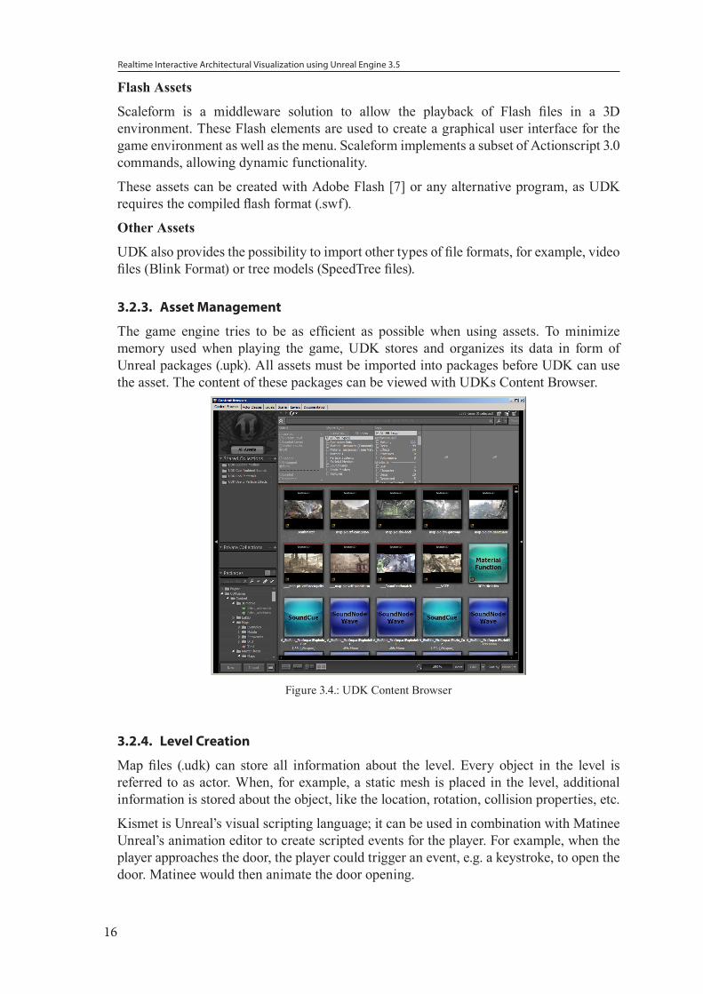
3.2.3. Asset Management
The game engine tries to be as efficient as possible when using assets. To minimize memory used when playing the game, UDK stores and organizes its data in form of Unreal packages (.upk). All assets must be imported into packages before UDK can use the asset. The content of these packages can be viewed with UDKs Content Browser.
Figure 3.4.: UDK Content Browser
3.2.4. Level Creation
Map files (.udk) can store all information about the level. Every object in the level is referred to as actor. When, for example, a static mesh is placed in the level, additional information is stored about the object, like the location, rotation, collision properties, etc.
Kismet is Unreal’s visual scripting language; it can be used in combination with Matinee Unreal’s animation editor to create scripted events for the player. For example, when the player approaches the door, the player could trigger an event, e.g. a keystroke, to open the door. Matinee would then animate the door opening.
Realtime Interactive Architectural Visualization using Unreal Engine 3.5
17
To create a playable level, a starting location in form of a player spawn point has to be defined, basic geometry and a light actor has to be placed.
3.2.5. Programming/Scripting
The UDK can be modified with configuration files and with the UnrealScript language. The C++ interface of the Unreal Engine 3, however, is not available for the UDK.
The core settings are designed for gaming purposes, limiting game time, providing a player inventory, etc. These settings are configured in a “game type” class and a “player controller” class.
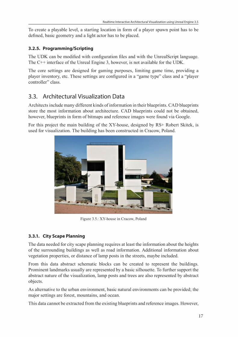
3.3. Architectural Visualization DataArchitects include many different kinds of information in their blueprints. CAD blueprints store the most information about architecture. CAD blueprints could not be obtained, however, blueprints in form of bitmaps and reference images were found via Google.
For this project the main building of the XY-house, designed by RS+ Robert Skitek, is used for visualization. The building has been constructed in Cracow, Poland.
Figure 3.5.: XY-house in Cracow, Poland
3.3.1. City Scape Planning
The data needed for city scape planning requires at least the information about the heights of the surrounding buildings as well as road information. Additional information about vegetation properties, or distance of lamp posts in the streets, maybe included.
From this data abstract schematic blocks can be created to represent the buildings. Prominent landmarks usually are represented by a basic silhouette. To further support the abstract nature of the visualization, lamp posts and trees are also represented by abstract objects.
As alternative to the urban environment, basic natural environments can be provided; the major settings are forest, mountains, and ocean.
This data cannot be extracted from the existing blueprints and reference images. However,
Realtime Interactive Architectural Visualization using Unreal Engine 3.5
18
other tools, like Google Earth, can provide access to such types of data. As alternative, random generated city data can be used for a proof of concept.
3.3.2. Main Building Visualization
Data about the exterior design and floor layout of a building are usually stored in form of blueprints as well as reference images. This data can be used to model the building as well as indicate the usage of different rooms. Room usage can be displayed in an abstract fashion; it is also common to include furniture.
3.3.3. Other Data that could be Visualized
The following data, if available, could be also shown in the visualization:
• Information about the pipe works or electrical wiring could be displayed by making the walls transparent.
• Historic data of a building that show the modifications made over time
• Multiple design ideas for a facade
• Information about escape routes of a building in the form of animated arrows
3.4. Interactive ElementsThe user should be able to interact with the environment by being able to control various aspects of the visualization. Besides basic interactions, the user should be able to control the time of day and to switch between the surrounding environments.
3.4.1. Basic interactions
The user should be able to walk around the environment and explore the building from any angle. He should be able to open doors and activate artificial lighting in the environment.
3.4.2. Time of Day Lighting
A time of day visualization is used to determine how the building will be lit by the sun at any time of the day. This visualization can uncover potential lighting problems and influence the placement of windows.
3.5. Technical SpecificationsThe minimum hardware requirements to run the visualization is:
• 2.0+ GHz processor
• 2 GB system RAM
• SM3-compatible video card
• 3 GB Free hard drive space
Realtime Interactive Architectural Visualization using Unreal Engine 3.5
19
4. Maya Plugin UDKToolboxWe decided to use Autodesk Maya, because it provides several tools to import CAD data and to create assets for the Unreal Engine; however, the process using the default Maya tools is very time consuming and requires multiple repetitive steps that make it inefficient and error prone. To increase efficency, we designed a plugin to automate parts of this process and increase the efficiency when creating assets for UDK.
In this chapter we describe the FBX workflow, the requirements for writing the plugin, and the features we provide with the plugin. In the end we will present the optimized workflow and discuss its limitations.
4.1. Analyzing the WorkflowWe analyzed the proposed FBX workflow from Epic Games [10]. In addition, we observed students using it. Potential issues were uncovered and used as requirements for defining features.
4.1.1. FBX workflow
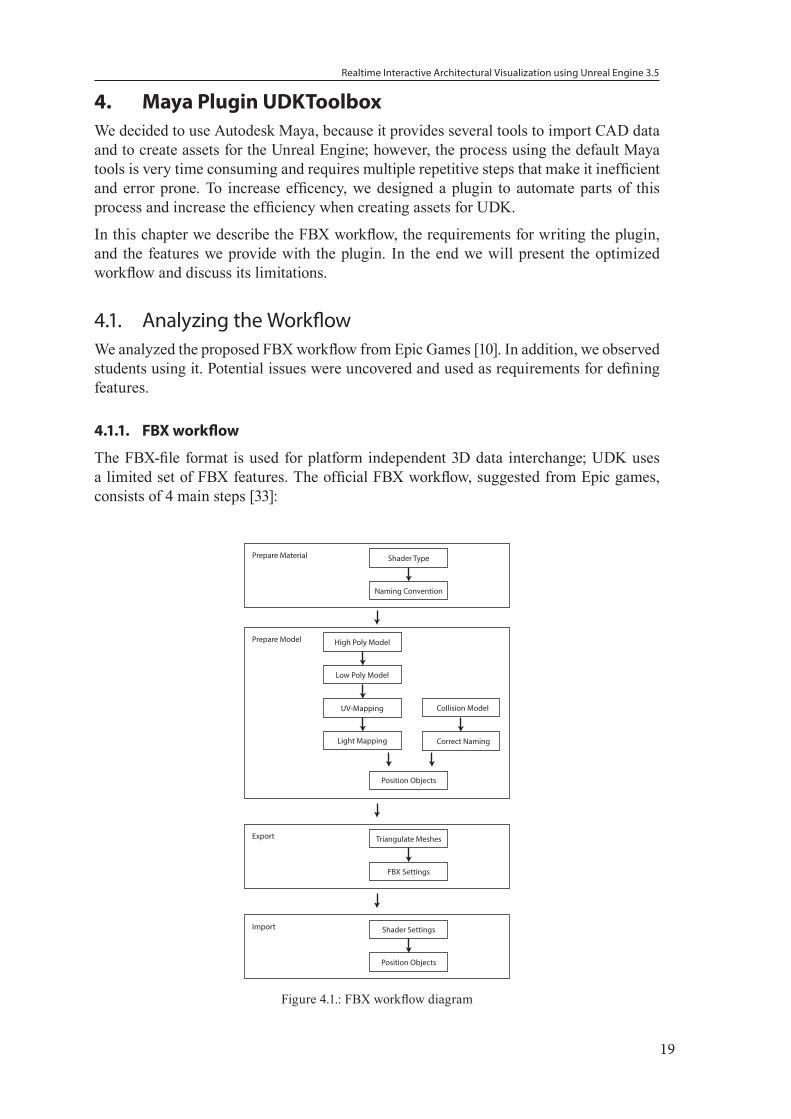
The FBX-file format is used for platform independent 3D data interchange; UDK uses a limited set of FBX features. The official FBX workflow, suggested from Epic games, consists of 4 main steps [33]:
Prepare Material Shader Type
Naming Convention
Export Triangulate Meshes
FBX Settings
Import Shader Settings
Position Objects
Light Mapping
Prepare Model High Poly Model
Low Poly Model
UV-Mapping
Position Objects
Collision Model
Correct Naming
Figure 4.1.: FBX workflow diagram
Realtime Interactive Architectural Visualization using Unreal Engine 3.5
20
Preparing the Material
As first step we select the material type. UDK only supports the basic types of materials (lambert, blinn, or phong shader). More advanced materials, like mental rays “mia_material”, are not supported and cause import errors.
Similar limitations apply to texture files. All textures used must be stored as Targa or Tiff file. For asset management purposes, it is best practice to name the textures with an identifying prefix, like “TEX_”, to ensure that the texture file has a unique identifier.
Preparing the Model
Architectural data is stored in the form of CAD data. This data is imported in Maya as NURBS geometry that has to be converted to polygonal geometry. The topology should consist entirely of quads or triangles. When processing the model, it usually consist of multiple objects that have to be unified.
To optimize the model for performance as few as possible polygons should be used. Normal maps can be used to add details without increasing the polygon count [77]. To create normal maps, a high-poly object and the corresponding low-poly object is needed; it is calculated by measuring the difference between the objects and storing the data in an image file.
The model requires a second UV-map to serve as lightmap [76]. It is important to note that to avoid artifacts, the UV-shells in the map do not touch each other and the map requires a minimum of 5% padding.
It is optional to include a collision model. A collision model is a tightly fit low polygonal object encompassing the original object to be used in the physics simulation of UDK. 3D artists can model a collision model manually; in many cases it is sufficient to use simple primitive objects, like cubes or spheres. UDK associates the collision model with its model through a naming convention. The collision model must have the same name as the original-model with the prefix “UCX_” attached. During the import process UDK analyses the object names and automatically combines the two objects to a single object. Alternatively many types of collision models can be generated manually by the game engine.
Exporting the Model with Material
In Maya it is required that the FBX-Exporter has to be enabled. It is a UDK requirement that every model has to be exported as its own file.
The final 3D model must consist entirely of triangular polygons. This can be ensured by enabling “Triangulation” in the FBX-export settings. The UDK specific export options can be stored as an individual preset file.
Information of the location of the pivot point is not exported. UDK assumes the pivot point is at the origin. It is best practice to position all objects at the orgin to avoid placement errors.
Importing the Model with Material
The positions of the objects created in Maya are not transferred. To accuratly reproduce the positioning in Maya, the positions need to be converted from Maya units to Unreal units and manually entered for each object.
Realtime Interactive Architectural Visualization using Unreal Engine 3.5
21
Further, translucent materials are imported as solid material and have to be adjusted in the material editor.
4.1.2. Observations
The participants of the course “Project Competence Multimedia: Unreal Development” [47] had the task of creating a simple game using the Unreal Engine. While working on the game several observations were made:
General
In many cases the students could not successfully export objects, they were puzzled what went wrong. In most cases, it was a simple typing error in naming the collision object. In other cases, it was because the mesh was not triangulated, or it had a faulty topology. Even after several successful exports, the students still failed at the export process. The team leaders provided a step-by-step guide that simultaneously served as checklist for the export process.
It was observed that already exported objects were imported to Maya to verify that objects were at the right scale.
Grid size
When the students were working on UDK related objects, they set grid size to the same size used in the Unreal Engine. However, the students found themselves switching constantly from the common Maya grid size to the Unreal grid size depending on the project they were working on.
Scene organization
To organize the scene the students used the display-layer features of Maya. They created their own layer “collisions” to store the associated collision objects.
Errors
Even after having learned how to export objects successfully and using the guilde, the students experienced the same errors in the exporting process. In most cases, the lightmap was missing
4.1.3. Conclusions
Even though the FBX workflow has only four major steps, the steps are complicated and errors do occur. Many of the errors could be avoided if the user had tools augmenting the process.
The most time consuming process is laying out objects. This process is further lengthened by not having the ability to export the positions from Maya to UDK. This forces the user to repeat this task. Automating this process would significantly increase efficiency for architectural visualizations.
In addition, these processes could be also automated:
• The creation of primitive collision objects
• Creation of primitive lightmaps
• Export of multiple objects to single files.
Realtime Interactive Architectural Visualization using Unreal Engine 3.5
22
4.2. Plugin DevelopmentMaya has a built-in coding environment, though, for most programming tasks it appears not to be well suited. We present here the tools used while creating the plugin.
4.2.1. Prior Plugins
For the Unreal Engine 2, before the FBX workflow was introduced, Epic Games had its own dedicated ActorX plugin for Maya to handle the export of objects. However, this plugin was discontinued [67]. The plugin exported single objects correctly. Most features were dedicated to the correct export of animated objects.
4.2.2. Programming Language
Maya supports several programming languages: Maya Embedded Language (Mel), Python, PyMel, C++, and QT. Developing C++/QT-Plugins have the highest performance and widest range of features. The compiled code is constrained to a specific version of Maya. The Mel code and Python code share practically the same interface. However, Mel code lacks performance and object oriented programming. We decided to use the PyMel Maya API to create the plugin because it supports object oriented programming.
4.2.3. Development Environment
Maya has a built in “script editor” with the capability of highlighting code. Using this editor automatically adds the code to the running environment. In many cases, declared variables cannot be changed without restarting Maya.
An external development environment allows generating random named files that are loaded as code to Maya and allow quick changes to the code. We used Eclipse as IDE with the PyDev Extension and the Eclipse Maya Editor 3.0.0. The PyDev Extension was configured to use the Maya native Python 2.7 interpreter. In addition, auto completion features were enabled by using the Maya pypredef files.
4.2.4. Source Versioning Tools
While developing the plugin, the Perforce software version management was used. Perforce enables subversioning of UDK, Maya, and Python script files [53].
4.2.5. Testing
We tested the plugin on Maya 2013 SP2 on Windows 7 64bit. We did not test it on other types of operating systems because UDK only runs on the Windows platform.
4.3. Plugin for Optimized WorkflowFeatures derived from the observations as well as minor scripts for workflow enhancements were added to the final feature set.
4.3.1. Fast Grid Size Switching
Though not mentioned in the FBX workflow, Unreal uses its own “Unreal Units (uu)”-
Realtime Interactive Architectural Visualization using Unreal Engine 3.5
23
format 1 cm = 0.525 uu [72]. 3D artists usually work with a grid size based on meters or centimeters [26]. The default Maya grid size is based on centimeters. The user has to open several submenus to change these settings.
The plugin allows the user to switch between the centimeter grid size and the UDK grid size with the push of a single button.
4.3.2. Reference 3D Models
In game development, reference objects are represented by a simple cube. These cubes can be used in the level creation process and are replaced by fully modeled objects. A simple feature to quickly create cubes of appropriate sizes was added to the plugin.
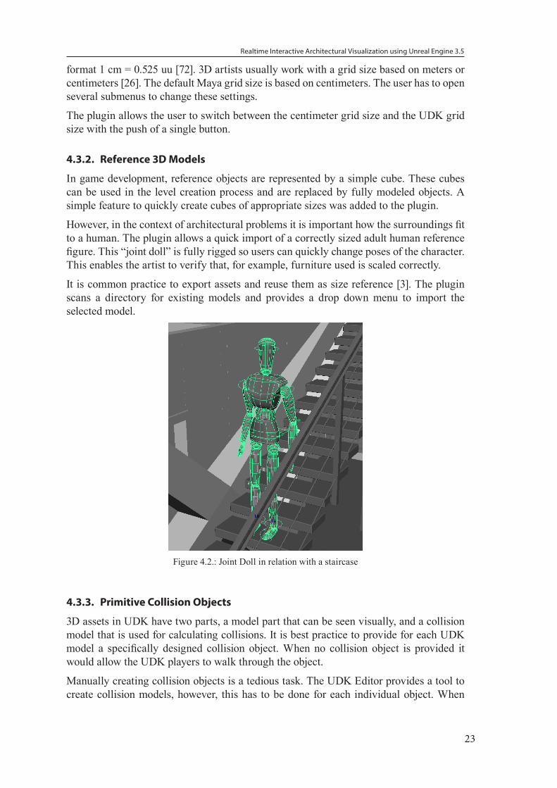
However, in the context of architectural problems it is important how the surroundings fit to a human. The plugin allows a quick import of a correctly sized adult human reference figure. This “joint doll” is fully rigged so users can quickly change poses of the character. This enables the artist to verify that, for example, furniture used is scaled correctly.
It is common practice to export assets and reuse them as size reference [3]. The plugin scans a directory for existing models and provides a drop down menu to import the selected model.
Figure 4.2.: Joint Doll in relation with a staircase
4.3.3. Primitive Collision Objects
3D assets in UDK have two parts, a model part that can be seen visually, and a collision model that is used for calculating collisions. It is best practice to provide for each UDK model a specifically designed collision object. When no collision object is provided it would allow the UDK players to walk through the object.
Manually creating collision objects is a tedious task. The UDK Editor provides a tool to create collision models, however, this has to be done for each individual object. When
Realtime Interactive Architectural Visualization using Unreal Engine 3.5
24
creating the collision model in Maya, the model has to be placed at the exact same position as the original object and named correctly.
The plugin provides three ways to create basic collision objects: Box, sphere, and duplication.
The box collision object can be used for most parts of a building, like windows, walls, floors, and ceilings. The plugin calculates a bounding box around the object and then creates it as a collision object.
The sphere collision object is suited for complex and round shapes, like chandeliers. The radius of the collision sphere is calculated based on the size of the bounding box.
Collision objects created by duplication provide a quick way to test complex objects in the UDK.
The plugin names the collision object correctly and parents it to the original object. This ensures that object and collision object move together.
4.3.4. UV-Mapping and Lightmaps
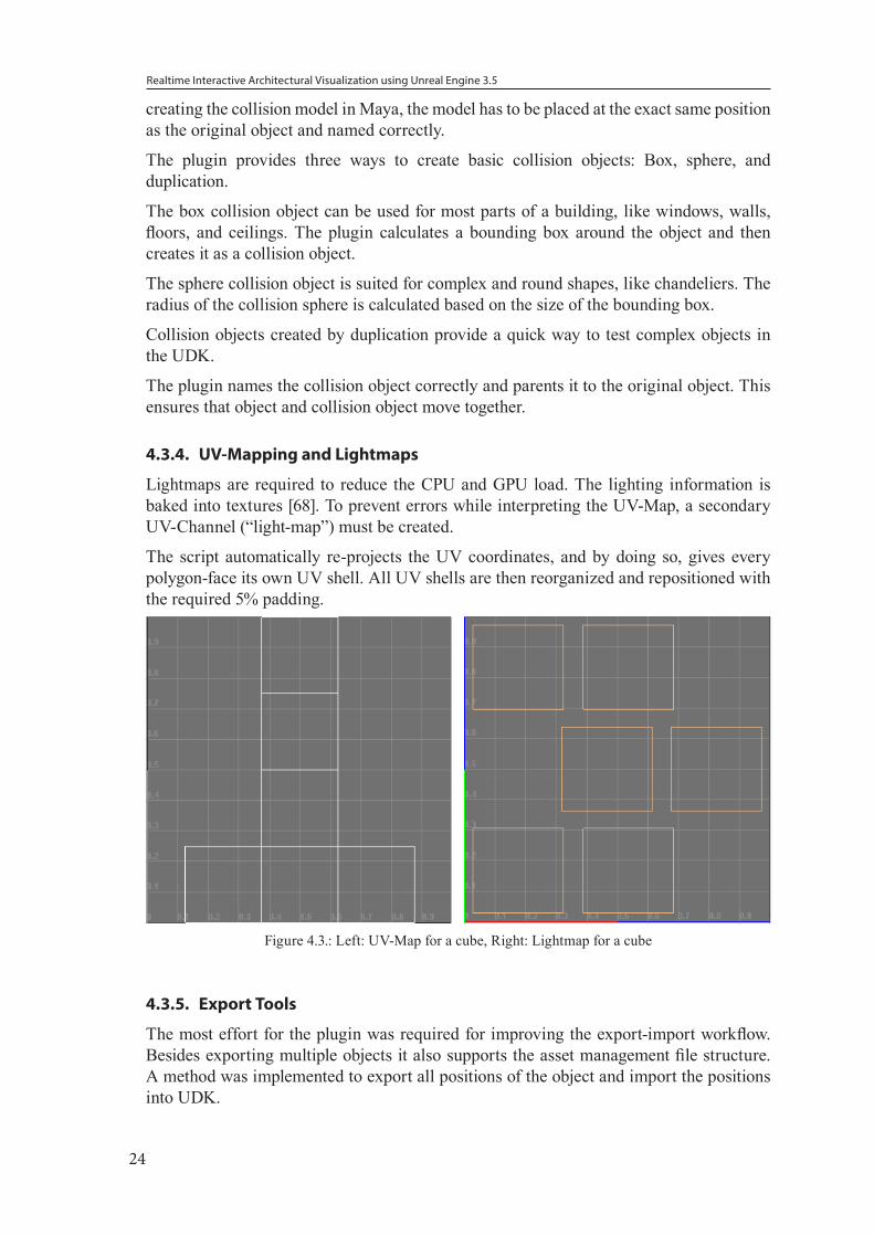
Lightmaps are required to reduce the CPU and GPU load. The lighting information is baked into textures [68]. To prevent errors while interpreting the UV-Map, a secondary UV-Channel (“light-map”) must be created.
The script automatically re-projects the UV coordinates, and by doing so, gives every polygon-face its own UV shell. All UV shells are then reorganized and repositioned with the required 5% padding.
Figure 4.3.: Left: UV-Map for a cube, Right: Lightmap for a cube
4.3.5. Export Tools
The most effort for the plugin was required for improving the export-import workflow. Besides exporting multiple objects it also supports the asset management file structure. A method was implemented to export all positions of the object and import the positions into UDK.
Realtime Interactive Architectural Visualization using Unreal Engine 3.5
25
Direct Transfer of Map
We explored the possibility of creating a direct connection between the UDK Editor and Maya with the help of C++ or network features. Due to limitations by Epic Games for the UDK we determined this was not possible. Thus the user has to manually import the exported assets.
Asset Management
A commonly overlooked feature of UDK is that all imported assets keep a reference to the original FBX-file. Exporting all files in the same folder structure allows rapid re-import of assets.
The main scene folders to create are: “sourceimages” (for textures/Photoshop files), “scenes” (for Maya scene files), and “fbxExport” (for the original FBX-files).
The plugin has the option to always export FBX-files to the same folder.
Shader Naming
A minor timesaver was introduced to automatically add a prefix “MAT_” to the material name and the prefix “TEX_” texture files. This ensures a standardized format and uniqueness of the names avoiding common errors.
Multiple Mesh Export
The standard export operation exports all selected objects to a single file. UDK, however, needs every object stored in its own file. Initially we created a method to move the object to the origin, then export each object as a single file, and then move the objects back to its original position.
While this is the correct way to export optimized assets for the UDK, it is only needed if assets have to be reusable. As in architectural projects the geometry of the building is unique, it makes this feature unnecessary. To reduce the complexity of the plugin, we removed this feature in the final version.
T3D - Level Export
To export the level correctly, besides the model itself, the positions, rotation, and scale of the assets have to be stored, and then imported to a UDK map.
While researching the problem, no solution could be found using the official documentation. Even the deprecated official ActorX plugin did not offer this feature. However, we discovered that UnrealText file format (.t3d) is used for level import. The main use for the file format is to allow the import of custom BSP-Brushes. This file format is deprecated and no official documentation is available for the file format [71].
To investigate the file format, we exported a level and discovered that information is stored in plain text. The text is structured simililar to a markup-language. Methodically we removed data structures and then reimported the file to see if the remaining information was still importable.
The initial file had 35000 lines. We noticed that texture files were represented in binary. Simply removing the binary data from the file resulted in errors. Removing the entire “PackageTexture” section of the file allowed the remaining data to be imported without problems. It became apparent that the UnrealText file did not store any information about
Realtime Interactive Architectural Visualization using Unreal Engine 3.5
26
the 3D geometry and only stored a reference to the corresponding Unreal Package that contained the object.
We removed all information not directly related to the static mesh UDK actor. We also removed the “MapPackage” and “Surface” sections of the code. The import of the remaining 24 lines of code worked without problems.
The file now contained just information about attributes regarding the actors that were being set by default. As we were only interested in the location, rotation, and scale attributes of the object, all other attributes were removed. The file was reimported successfully. However, there were no rotation and scale attributes defined in the file.
We speculated by using a different actor and setting values for the rotation and scale attributes that the information would be stored in the t3d file. We repeated the entire process and, as expected, the attributes “DrawScale3D” and “Rotation” showed up in the t3d file.
This provided us the basis for writing the function “export_T3D” to generate the file based on the objects present in the Maya scene. The script adds a unique “Actor” block for every object and converts the translation and scale from cm to uu. Rotation values are represented with the full integer range in UDK, so the Maya rotation values have to be converted with angle/360 * sys.maxint. An example of a t3d file is shown in the appendix.
It is important to note that this method only works for objects that are already present in UDK packages.
Transfer of the Scene from Maya to UDK
In the final implementation, the “level export” exports all objects as FBX-files and stores them in a folder, the folder name indicates the package name while importing these objects in UDK. In addition it exports the t3d file.
Due to the lack of a direct connection between Maya and UDK the user must manually import the FBX-files to the correct package, then save the package, and finally import the t3d file.
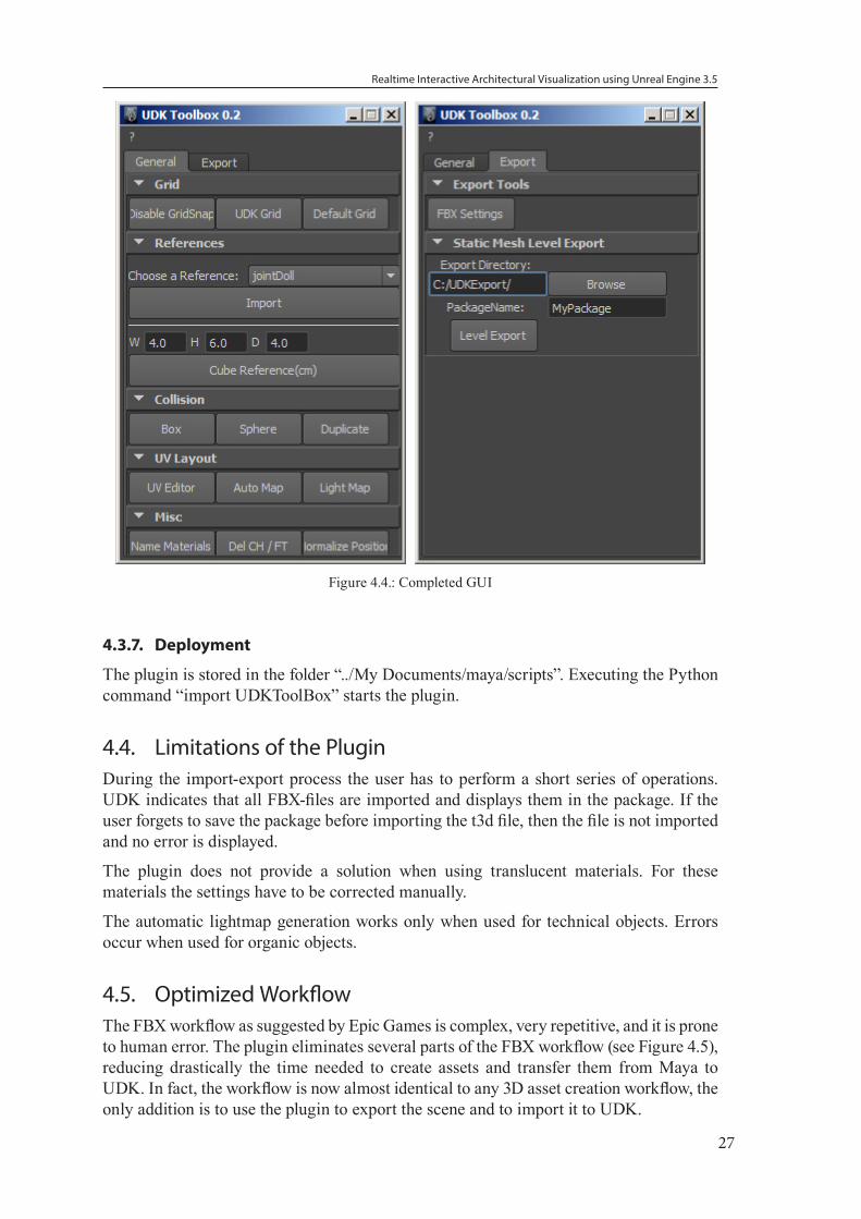
4.3.6. User Interface
The user interface was created using the default Maya Python API. The PyQT interface was not used as no callback functions were required for the interface.
Visual cues from the Maya Attribute Editor interface were used to design the plugin. Functions are organized in two tabs “General” and “Export”.
Realtime Interactive Architectural Visualization using Unreal Engine 3.5
27
Figure 4.4.: Completed GUI
4.3.7. Deployment
The plugin is stored in the folder “../My Documents/maya/scripts”. Executing the Python command “import UDKToolBox” starts the plugin.
4.4. Limitations of the PluginDuring the import-export process the user has to perform a short series of operations. UDK indicates that all FBX-files are imported and displays them in the package. If the user forgets to save the package before importing the t3d file, then the file is not imported and no error is displayed.
The plugin does not provide a solution when using translucent materials. For these materials the settings have to be corrected manually.
The automatic lightmap generation works only when used for technical objects. Errors occur when used for organic objects.
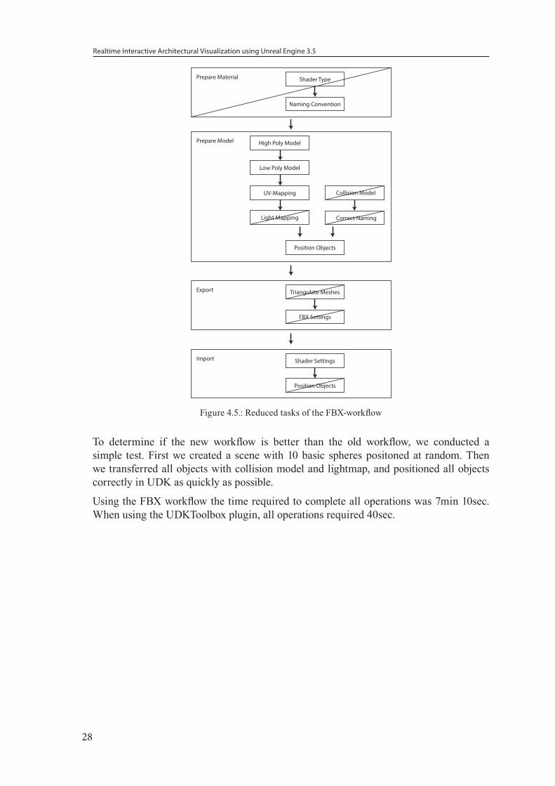
4.5. Optimized Workflow The FBX workflow as suggested by Epic Games is complex, very repetitive, and it is prone to human error. The plugin eliminates several parts of the FBX workflow (see Figure 4.5), reducing drastically the time needed to create assets and transfer them from Maya to UDK. In fact, the workflow is now almost identical to any 3D asset creation workflow, the only addition is to use the plugin to export the scene and to import it to UDK.
Realtime Interactive Architectural Visualization using Unreal Engine 3.5
28
Prepare Material Shader Type
Naming Convention
Export Triangulate Meshes
FBX Settings
Import Shader Settings
Position Objects
Light Mapping
Prepare Model High Poly Model
Low Poly Model
UV-Mapping
Position Objects
Collision Model
Correct Naming
Figure 4.5.: Reduced tasks of the FBX-workflow
To determine if the new workflow is better than the old workflow, we conducted a simple test. First we created a scene with 10 basic spheres positoned at random. Then we transferred all objects with collision model and lightmap, and positioned all objects correctly in UDK as quickly as possible.
Using the FBX workflow the time required to complete all operations was 7min 10sec. When using the UDKToolbox plugin, all operations required 40sec.
Realtime Interactive Architectural Visualization using Unreal Engine 3.5
29
5. UDK FrameworkIn this chapter we will discuss how we extended the Unreal Engine to serve as a framework for architectural visualization.
5.1. UDK Framework DesignOur goal was to develop an open framework that not only could support our prototype for architectural visualization but to also allow rapid display of other types of architecture and to make it extensible for including new features.
5.1.1. UDK Terminology
Visualization is treated the same way as a UDK Game. To create a UDK Game, four major components are needed [8]: A game definition (written in UnrealScript), an Unreal Package (containing the assets), an Unreal Map (defining the environment), and the game engine configuration files. The UDK Editor is used to create Unreal Maps, similar to a Maya scene, and Unreal Packages. A standard text editor is used to create Unreal Script files and configuration files.
UDK Maps
Maps (also called levels) store information about the environment, properties of actors (position, rotation, etc.) and Kismet, Unreal’s visual scripting engine. A UDK actor is defined by a reference to an object in an UnrealPackage or an instance of an actor-class-object. Examples of actors are: “static mesh”, “lights” etc.
A “spawn point” actor defines the location of the player when the game starts. The starting map must contain a “spawn point”.
Additional maps can be loaded during runtime using level streaming methods.
UDK Packages
UDK packages are independent from UDK maps. They are optimized to store and manage assets. The package compresses and optimizes the assets to minimize memory consumption. The size of a package should not exceed 256MB.
A special package component is a Prefab. Prefabs are collections of actors and associated Kismet that are stored in a package and are reusable. For example, to open a door in UDK, the mesh, a trigger, a matinee sequence to animate the door opening and its Kismet script are stored as prefab.
Unreal Script Classes
Unreal Script Classes define the game type, player handling, Kismet nodes, and Actor Classes.
UDK has several types of games available. For example, “UT-Deathmatch” uses the first-person perspective. This game type can be modified to suit architectural visualization. While visualization is not a game, to access the rendering capabilities of the Unreal Engine, a simple UDK Gametype without game elements must be defined.
When Unreal Script files are modified, the code must be recompiled, and the UDK Editor or UDK Game has to be restarted.
Realtime Interactive Architectural Visualization using Unreal Engine 3.5
30
Game Engine Configuration Files
Many settings concerning the render engine are set in the configuration files, for example, “Anti-Aliasing-Quality” settings or display resolution.
5.1.2. Ideal workflow for architectural visualization with UDK
The artist/architect should only have to import the building and the rest of the system is already configured to present the building in UDK.
To accomplish this goal, we identified potential elements that are present in every type of architectural visualization. If possible, these elements should only be created once and then reused in further architectural visualization projects.
5.1.3. Framework Setup
We created following structure for the framework:
UDK Maps
Unreal has the possibility of “Level streaming”, this allows multiple maps to be combined at runtime into a single map. The original map is then called the “Persistent Level”, which serves at the same time as the startup level. The feature is used to create a seemingly endless environment without the need for loading screens.
In our framework, however, we are using it simply as a layer organization tool. Multiple levels are used to manage the featueres in dedicated maps. Parts of the visualization are split into different categories and their corresponding maps: “building”, “Kismet scripts”, “time of day”, “city environment”, “nature environment”, “helper assets”.
The benefit of such a setup is that now only the “building”-map has to be exchanged to create a different architectural visualization. In addition, the level setup can be easily extended with features if necessary.
UDK Packages
The uniqueness of every architectural project is the actual building. Separating the geometry of the building and the materials into its own package allows the materials created for the visualization to be reused.
Prefabs are stored in the “architectural_visualization_assets” package.
Unreal Script Classes
The framework includes an architectural visualization game type class to control the engine that does not have to be further modified.
Game Engine Configuration Files
The Unreal Engine configuration files are modified depending on the hardware used. However, the configuration settings can be set to a low-end environment removing the need to modify these files further.
5.1.4. Asset Management
UDK organizes its assets in packages (.upk). However, to create assets for UDK one has to utilize a 3D content creation tool for mesh creation, as well as 2D imaging programs for
Realtime Interactive Architectural Visualization using Unreal Engine 3.5
31
texturing and a Flash authoring tool. For this project, Autodesk Maya, Adobe Photoshop, and Adobe Flash were used for asset creation.
3D Asset Management
3D models are stored as maya-Ascii-files (.ma) for maximal backwards compatibility. To separate the newly created assets from the UDK default files, the folder “Archviz” was added.
The “Maya” subfolder was set up as a default maya project folder, using “scenes” to store the maya files, “sourceimages” for textures/references (as well as Photoshop files).
The “FBX Export” subfolder stores the exported models.
2D Asset Management
2D Textures and images created in Photoshop are stored as Photoshop Files (.psd) and then exported as UDK readable Targa files (.tga).
Texture files have to be saved as square images with RGB or RGBA channels. For optimal performance, the texture files have a length represented by a power of two but not larger than 4096.
Flash File Management
UDK uses Scaleform to render GUI elements. Scaleform requires all Flash swf-files to be stored in the specific path “..\UDK\UDKGame\Flash”.
To use the Flash elements they have to be imported into their own Unreal package and then applied as a texture to an actor.
UDK Level Management
We are using the default directory “...\UDK\UDKGame\Content\Maps” to store the UDK-maps.
5.2. MaterialsMaterials used for architectural visualization should support the following attributes: diffuse reflections, specular reflections, and refractions. To demonstrate the material shader capabilites we are using a Utah teapot as standard reference object.
During the material creation process the artist should be communicating with the architect. It is easy to create material shaders that are visually pleasing, however, it may not be feasible to build the building with the suggested materials [41].
5.2.1. Default UDK Material
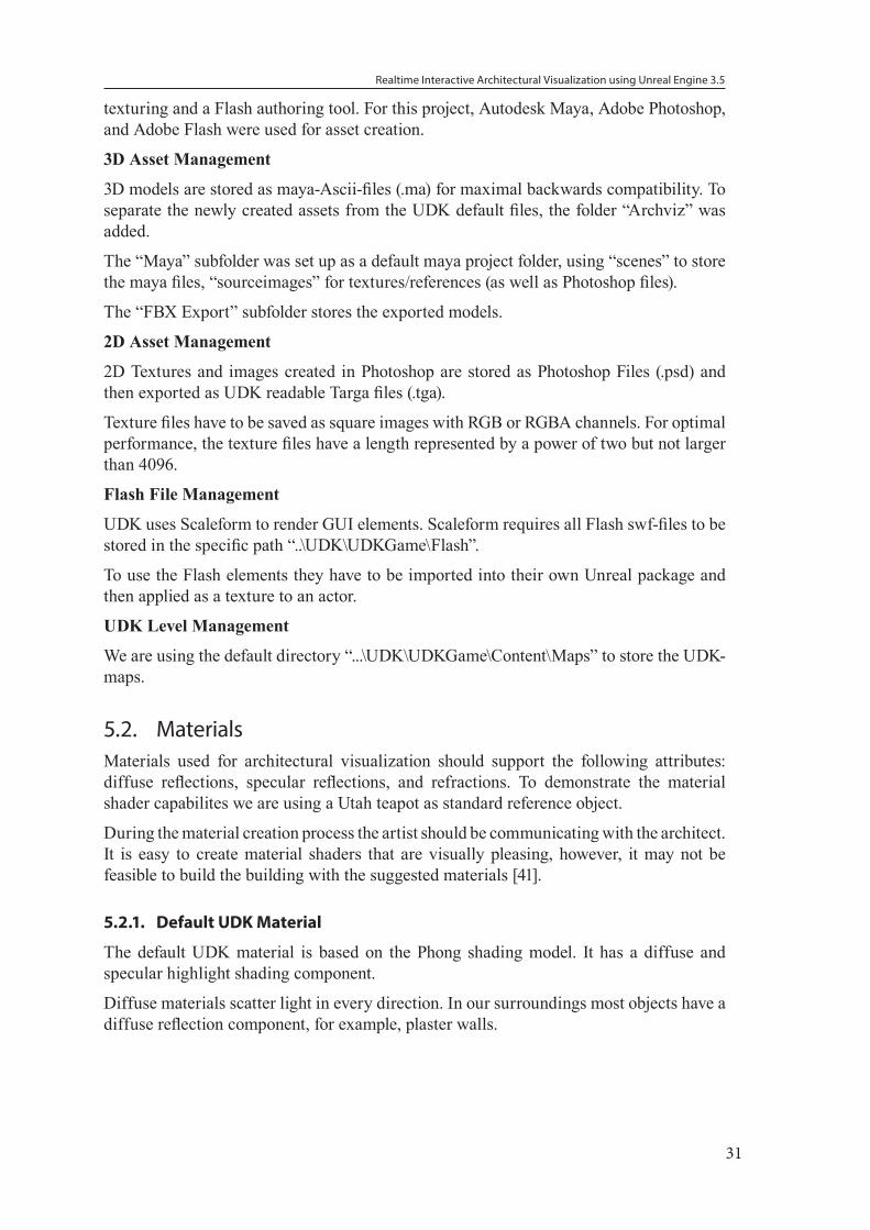
The default UDK material is based on the Phong shading model. It has a diffuse and specular highlight shading component.
Diffuse materials scatter light in every direction. In our surroundings most objects have a diffuse reflection component, for example, plaster walls.
Realtime Interactive Architectural Visualization using Unreal Engine 3.5
32
Figure 5.1.: Gray diffuse reflection
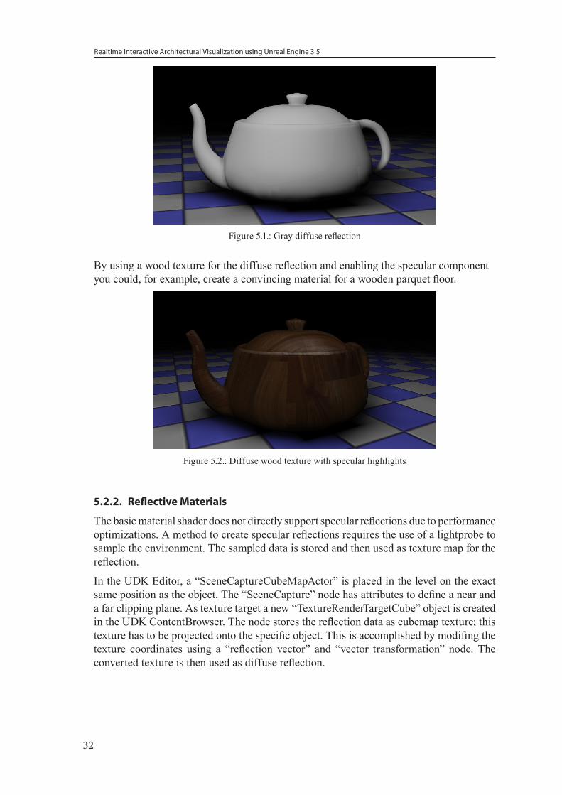
By using a wood texture for the diffuse reflection and enabling the specular component you could, for example, create a convincing material for a wooden parquet floor.
Figure 5.2.: Diffuse wood texture with specular highlights
5.2.2. Reflective Materials
The basic material shader does not directly support specular reflections due to performance optimizations. A method to create specular reflections requires the use of a lightprobe to sample the environment. The sampled data is stored and then used as texture map for the reflection.
In the UDK Editor, a “SceneCaptureCubeMapActor” is placed in the level on the exact same position as the object. The “SceneCapture” node has attributes to define a near and a far clipping plane. As texture target a new “TextureRenderTargetCube” object is created in the UDK ContentBrowser. The node stores the reflection data as cubemap texture; this texture has to be projected onto the specific object. This is accomplished by modifing the texture coordinates using a “reflection vector” and “vector transformation” node. The converted texture is then used as diffuse reflection.
Realtime Interactive Architectural Visualization using Unreal Engine 3.5
33
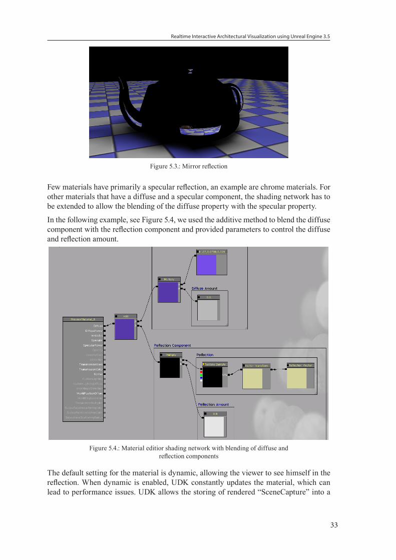
Figure 5.3.: Mirror reflection
Few materials have primarily a specular reflection, an example are chrome materials. For other materials that have a diffuse and a specular component, the shading network has to be extended to allow the blending of the diffuse property with the specular property.
In the following example, see Figure 5.4, we used the additive method to blend the diffuse component with the reflection component and provided parameters to control the diffuse and reflection amount.
Figure 5.4.: Material editior shading network with blending of diffuse and reflection components
The default setting for the material is dynamic, allowing the viewer to see himself in the reflection. When dynamic is enabled, UDK constantly updates the material, which can lead to performance issues. UDK allows the storing of rendered “SceneCapture” into a
Realtime Interactive Architectural Visualization using Unreal Engine 3.5
34
static texture file. Static reflections are calculated only once when the level is generated and then never updated.
In addition to the potential performance issues, the method requires that for each object that uses a direct reflection component, a unique material and accompanying light probe must be placed. This process can be very time consuming for the artist. It is generally discouraged to use reflective materials in UDK.
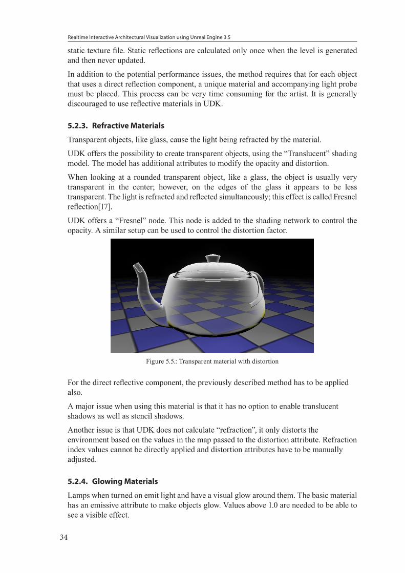
5.2.3. Refractive Materials
Transparent objects, like glass, cause the light being refracted by the material.
UDK offers the possibility to create transparent objects, using the “Translucent” shading model. The model has additional attributes to modify the opacity and distortion.
When looking at a rounded transparent object, like a glass, the object is usually very transparent in the center; however, on the edges of the glass it appears to be less transparent. The light is refracted and reflected simultaneously; this effect is called Fresnel reflection[17].
UDK offers a “Fresnel” node. This node is added to the shading network to control the opacity. A similar setup can be used to control the distortion factor.
Figure 5.5.: Transparent material with distortion
For the direct reflective component, the previously described method has to be applied also.
A major issue when using this material is that it has no option to enable translucent shadows as well as stencil shadows.
Another issue is that UDK does not calculate “refraction”, it only distorts the environment based on the values in the map passed to the distortion attribute. Refraction index values cannot be directly applied and distortion attributes have to be manually adjusted.
5.2.4. Glowing Materials
Lamps when turned on emit light and have a visual glow around them. The basic material has an emissive attribute to make objects glow. Values above 1.0 are needed to be able to see a visible effect.

Realtime Interactive Architectural Visualization using Unreal Engine 3.5
35
The glow does not actively emit light. However, the property can be used to create the material of the lampshades and by placing light sources near the lamp it appears that the lamp would be actively emitting light into the scene.
Figure 5.6.: Glowing material Glow Value 4.0
5.2.5. Adjusting Materials during Gameplay
The UDK shading system has the feature to use the “ParameterValue” nodes. These nodes function as named variables. An instance of the material can be created, however, the “ParameterValues” can be overridden. This allows complex shading networks to be easily reused for multiple variations of the material.
In addition, the system has the possibility to modify these values dynamically. To enable this functionality, the “MaterialInstance” has to be created, and a “MaterialInstanceActor” is added to the level for managing it. Using Kismet the “ParameterValues” can be set to a specific value. As alternative a “Matinee” sequence can be used to change the “ParameterValues” over time.
5.3. LightingWe discuss the basics of the UDK’s lighting system and how it can be used in an architectural context.
5.3.1. Light Placement
When lighting for animation is used it is common practice to use 3-point lighting: a key-light, fill-light, and rim-light. The light sources in most cases cannot be seen and can be simulated by using basic virtual lights [75].
However, this type of lighting setup is created based on the camera position. For lighting in interactive 3D environments it is important to place lights in a plausible fashion and independent from the camera. In addition, because the user can explore the environment, in most cases the user should be able to see the source of the light.
5.3.2. Direct Light
UDK provides four common basic light types: Point light, Spotlight, Directional Light, and Skylight (a type of ambient light).
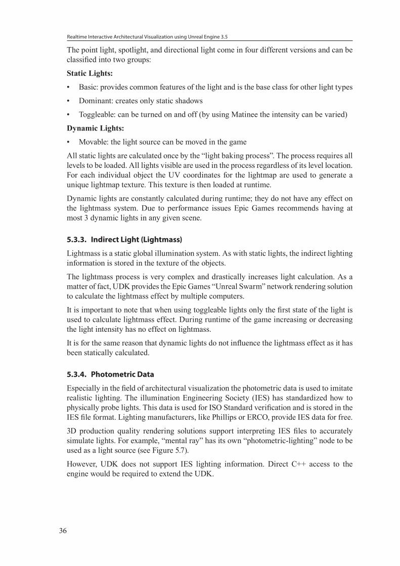
Realtime Interactive Architectural Visualization using Unreal Engine 3.5
36
The point light, spotlight, and directional light come in four different versions and can be classified into two groups:
Static Lights:
• Basic: provides common features of the light and is the base class for other light types
• Dominant: creates only static shadows
• Toggleable: can be turned on and off (by using Matinee the intensity can be varied)
Dynamic Lights:
• Movable: the light source can be moved in the game
All static lights are calculated once by the “light baking process”. The process requires all levels to be loaded. All lights visible are used in the process regardless of its level location. For each individual object the UV coordinates for the lightmap are used to generate a unique lightmap texture. This texture is then loaded at runtime.
Dynamic lights are constantly calculated during runtime; they do not have any effect on the lightmass system. Due to performance issues Epic Games recommends having at most 3 dynamic lights in any given scene.
5.3.3. Indirect Light (Lightmass)
Lightmass is a static global illumination system. As with static lights, the indirect lighting information is stored in the texture of the objects.
The lightmass process is very complex and drastically increases light calculation. As a matter of fact, UDK provides the Epic Games “Unreal Swarm” network rendering solution to calculate the lightmass effect by multiple computers.
It is important to note that when using toggleable lights only the first state of the light is used to calculate lightmass effect. During runtime of the game increasing or decreasing the light intensity has no effect on lightmass.
It is for the same reason that dynamic lights do not influence the lightmass effect as it has been statically calculated.
5.3.4. Photometric Data
Especially in the field of architectural visualization the photometric data is used to imitate realistic lighting. The illumination Engineering Society (IES) has standardized how to physically probe lights. This data is used for ISO Standard verification and is stored in the IES file format. Lighting manufacturers, like Phillips or ERCO, provide IES data for free.
3D production quality rendering solutions support interpreting IES files to accurately simulate lights. For example, “mental ray” has its own “photometric-lighting” node to be used as a light source (see Figure 5.7).
However, UDK does not support IES lighting information. Direct C++ access to the engine would be required to extend the UDK.
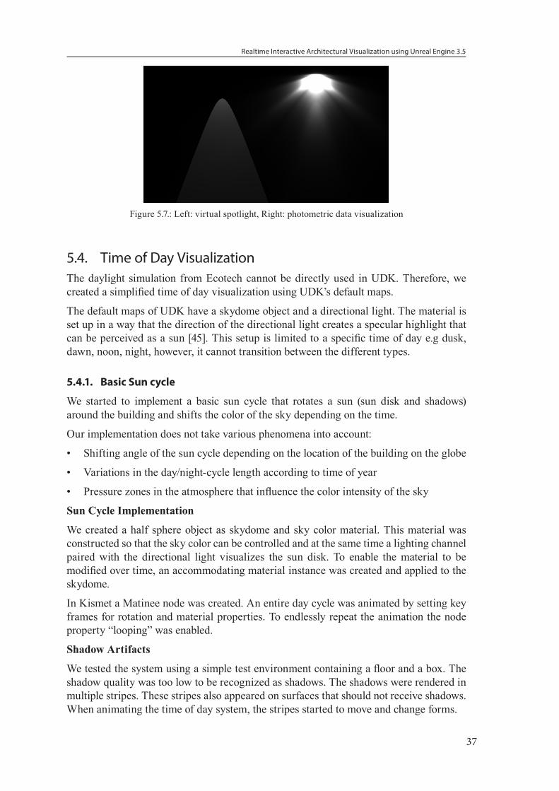
Realtime Interactive Architectural Visualization using Unreal Engine 3.5
37
Figure 5.7.: Left: virtual spotlight, Right: photometric data visualization
5.4. Time of Day VisualizationThe daylight simulation from Ecotech cannot be directly used in UDK. Therefore, we created a simplified time of day visualization using UDK’s default maps.
The default maps of UDK have a skydome object and a directional light. The material is set up in a way that the direction of the directional light creates a specular highlight that can be perceived as a sun [45]. This setup is limited to a specific time of day e.g dusk, dawn, noon, night, however, it cannot transition between the different types.
5.4.1. Basic Sun cycle
We started to implement a basic sun cycle that rotates a sun (sun disk and shadows) around the building and shifts the color of the sky depending on the time.
Our implementation does not take various phenomena into account:
• Shifting angle of the sun cycle depending on the location of the building on the globe
• Variations in the day/night-cycle length according to time of year
• Pressure zones in the atmosphere that influence the color intensity of the sky
Sun Cycle Implementation
We created a half sphere object as skydome and sky color material. This material was constructed so that the sky color can be controlled and at the same time a lighting channel paired with the directional light visualizes the sun disk. To enable the material to be modified over time, an accommodating material instance was created and applied to the skydome.
In Kismet a Matinee node was created. An entire day cycle was animated by setting key frames for rotation and material properties. To endlessly repeat the animation the node property “looping” was enabled.
Shadow Artifacts
We tested the system using a simple test environment containing a floor and a box. The shadow quality was too low to be recognized as shadows. The shadows were rendered in multiple stripes. These stripes also appeared on surfaces that should not receive shadows. When animating the time of day system, the stripes started to move and change forms.
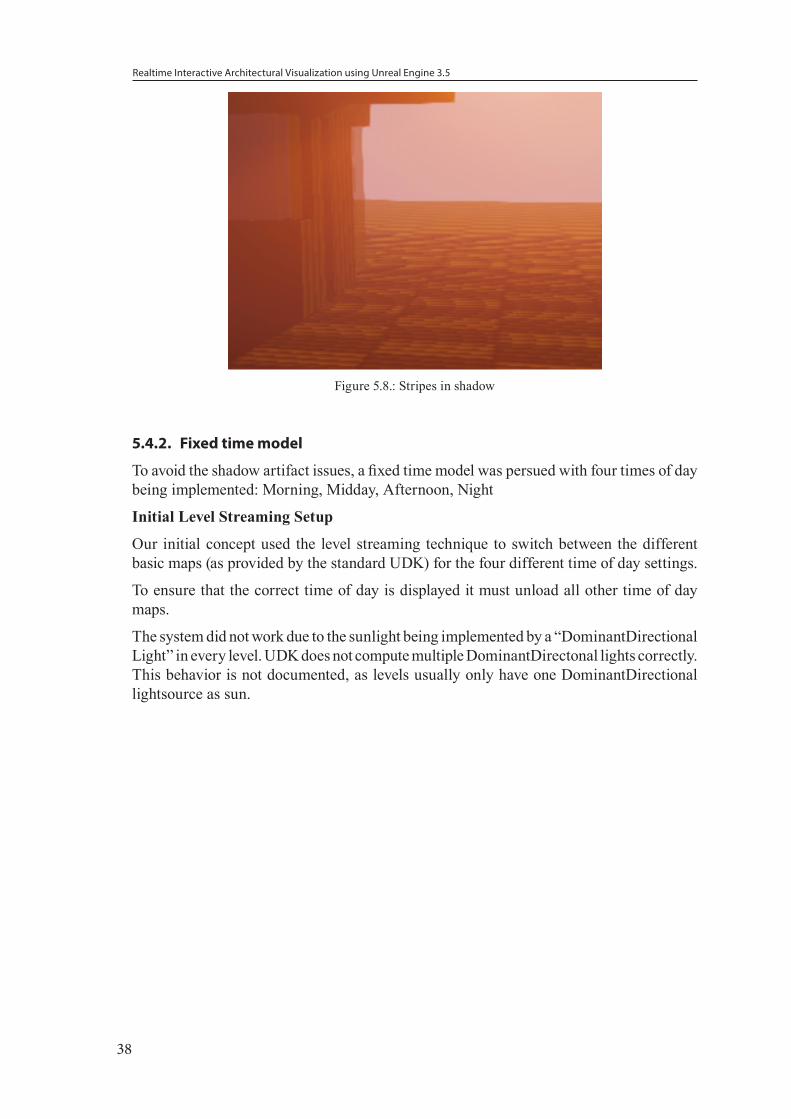
Realtime Interactive Architectural Visualization using Unreal Engine 3.5
38
Figure 5.8.: Stripes in shadow
5.4.2. Fixed time model
To avoid the shadow artifact issues, a fixed time model was persued with four times of day being implemented: Morning, Midday, Afternoon, Night
Initial Level Streaming Setup
Our initial concept used the level streaming technique to switch between the different basic maps (as provided by the standard UDK) for the four different time of day settings.
To ensure that the correct time of day is displayed it must unload all other time of day maps.
The system did not work due to the sunlight being implemented by a “DominantDirectional Light” in every level. UDK does not compute multiple DominantDirectonal lights correctly. This behavior is not documented, as levels usually only have one DominantDirectional lightsource as sun.
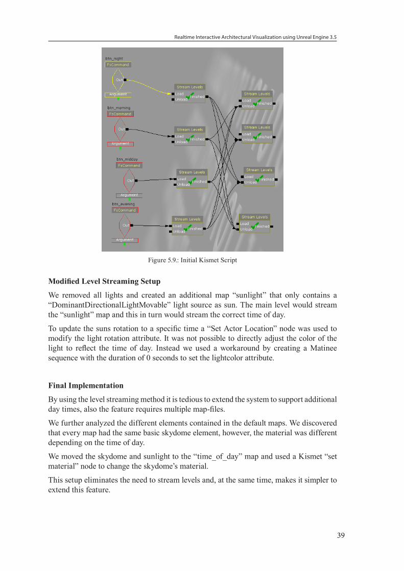
Realtime Interactive Architectural Visualization using Unreal Engine 3.5
39
Figure 5.9.: Initial Kismet Script
Modified Level Streaming Setup
We removed all lights and created an additional map “sunlight” that only contains a “DominantDirectionalLightMovable” light source as sun. The main level would stream the “sunlight” map and this in turn would stream the correct time of day.
To update the suns rotation to a specific time a “Set Actor Location” node was used to modify the light rotation attribute. It was not possible to directly adjust the color of the light to reflect the time of day. Instead we used a workaround by creating a Matinee sequence with the duration of 0 seconds to set the lightcolor attribute.
Final Implementation
By using the level streaming method it is tedious to extend the system to support additional day times, also the feature requires multiple map-files.
We further analyzed the different elements contained in the default maps. We discovered that every map had the same basic skydome element, however, the material was different depending on the time of day.
We moved the skydome and sunlight to the “time_of_day” map and used a Kismet “set material” node to change the skydome’s material.
This setup eliminates the need to stream levels and, at the same time, makes it simpler to extend this feature.
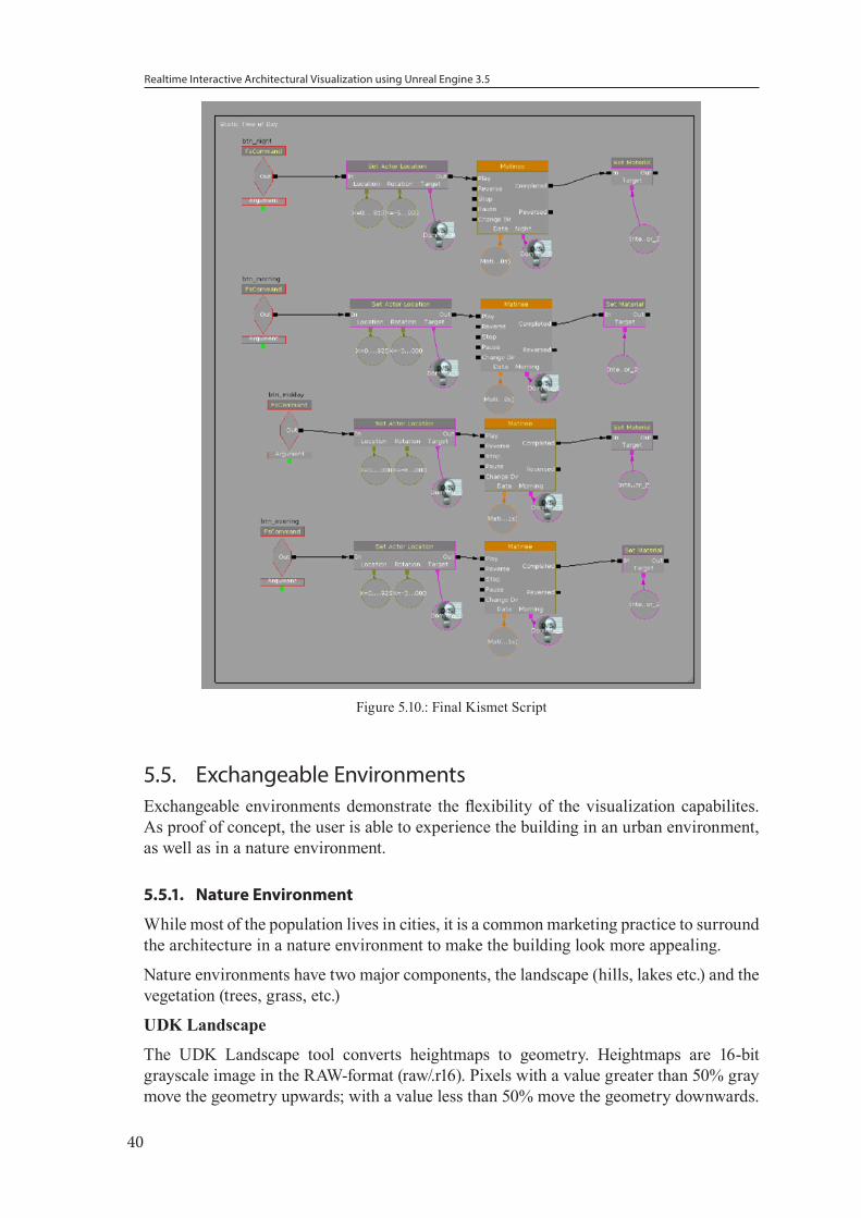
Realtime Interactive Architectural Visualization using Unreal Engine 3.5
40
Figure 5.10.: Final Kismet Script
5.5. Exchangeable EnvironmentsExchangeable environments demonstrate the flexibility of the visualization capabilites. As proof of concept, the user is able to experience the building in an urban environment, as well as in a nature environment.
5.5.1. Nature Environment
While most of the population lives in cities, it is a common marketing practice to surround the architecture in a nature environment to make the building look more appealing.
Nature environments have two major components, the landscape (hills, lakes etc.) and the vegetation (trees, grass, etc.)
UDK Landscape
The UDK Landscape tool converts heightmaps to geometry. Heightmaps are 16-bit grayscale image in the RAW-format (raw/.r16). Pixels with a value greater than 50% gray move the geometry upwards; with a value less than 50% move the geometry downwards.
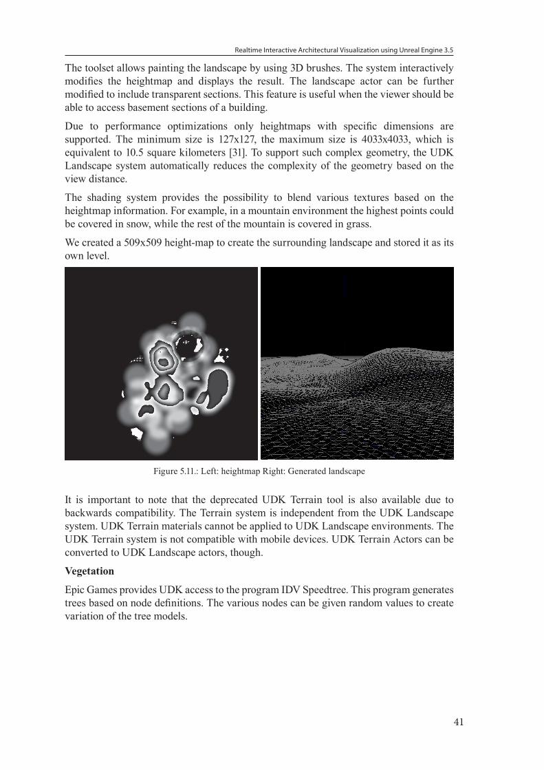
Realtime Interactive Architectural Visualization using Unreal Engine 3.5
41
The toolset allows painting the landscape by using 3D brushes. The system interactively modifies the heightmap and displays the result. The landscape actor can be further modified to include transparent sections. This feature is useful when the viewer should be able to access basement sections of a building.
Due to performance optimizations only heightmaps with specific dimensions are supported. The minimum size is 127x127, the maximum size is 4033x4033, which is equivalent to 10.5 square kilometers [31]. To support such complex geometry, the UDK Landscape system automatically reduces the complexity of the geometry based on the view distance.
The shading system provides the possibility to blend various textures based on the heightmap information. For example, in a mountain environment the highest points could be covered in snow, while the rest of the mountain is covered in grass.
We created a 509x509 height-map to create the surrounding landscape and stored it as its own level.
Figure 5.11.: Left: heightmap Right: Generated landscape
It is important to note that the deprecated UDK Terrain tool is also available due to backwards compatibility. The Terrain system is independent from the UDK Landscape system. UDK Terrain materials cannot be applied to UDK Landscape environments. The UDK Terrain system is not compatible with mobile devices. UDK Terrain Actors can be converted to UDK Landscape actors, though.
Vegetation
Epic Games provides UDK access to the program IDV Speedtree. This program generates trees based on node definitions. The various nodes can be given random values to create variation of the tree models.
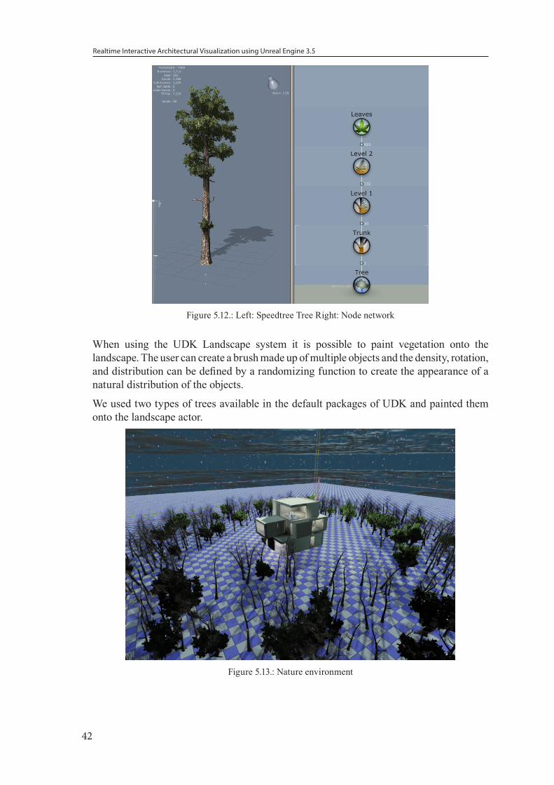
Realtime Interactive Architectural Visualization using Unreal Engine 3.5
42
Figure 5.12.: Left: Speedtree Tree Right: Node network
When using the UDK Landscape system it is possible to paint vegetation onto the landscape. The user can create a brush made up of multiple objects and the density, rotation, and distribution can be defined by a randomizing function to create the appearance of a natural distribution of the objects.
We used two types of trees available in the default packages of UDK and painted them onto the landscape actor.
Figure 5.13.: Nature environment
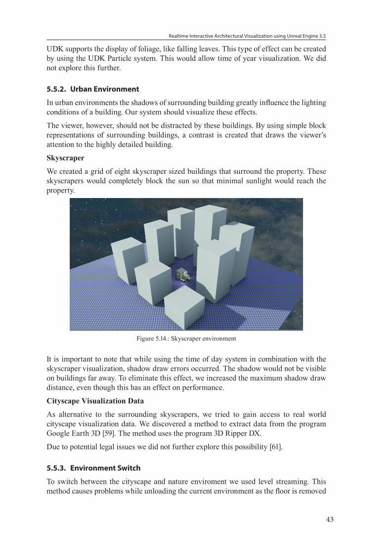
Realtime Interactive Architectural Visualization using Unreal Engine 3.5
43
UDK supports the display of foliage, like falling leaves. This type of effect can be created by using the UDK Particle system. This would allow time of year visualization. We did not explore this further.
5.5.2. Urban Environment
In urban environments the shadows of surrounding building greatly influence the lighting conditions of a building. Our system should visualize these effects.
The viewer, however, should not be distracted by these buildings. By using simple block representations of surrounding buildings, a contrast is created that draws the viewer’s attention to the highly detailed building.
Skyscraper
We created a grid of eight skyscraper sized buildings that surround the property. These skyscrapers would completely block the sun so that minimal sunlight would reach the property.
Figure 5.14.: Skyscraper environment
It is important to note that while using the time of day system in combination with the skyscraper visualization, shadow draw errors occurred. The shadow would not be visible on buildings far away. To eliminate this effect, we increased the maximum shadow draw distance, even though this has an effect on performance.
Cityscape Visualization Data
As alternative to the surrounding skyscrapers, we tried to gain access to real world cityscape visualization data. We discovered a method to extract data from the program Google Earth 3D [59]. The method uses the program 3D Ripper DX.
Due to potential legal issues we did not further explore this possibility [61].
5.5.3. Environment Switch
To switch between the cityscape and nature enviroment we used level streaming. This method causes problems while unloading the current environment as the floor is removed
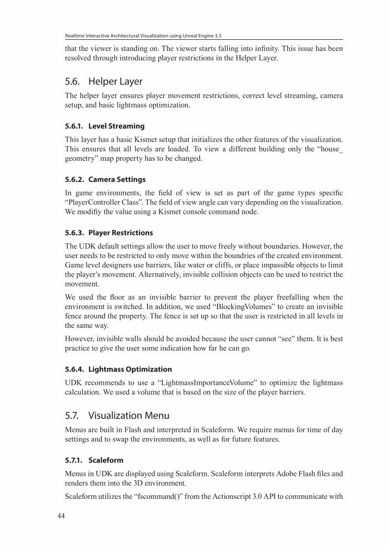
Realtime Interactive Architectural Visualization using Unreal Engine 3.5
44
that the viewer is standing on. The viewer starts falling into infinity. This issue has been resolved through introducing player restrictions in the Helper Layer.
5.6. Helper LayerThe helper layer ensures player movement restrictions, correct level streaming, camera setup, and basic lightmass optimization.
5.6.1. Level Streaming
This layer has a basic Kismet setup that initializes the other features of the visualization. This ensures that all levels are loaded. To view a different building only the “house_geometry” map property has to be changed.
5.6.2. Camera Settings
In game environments, the field of view is set as part of the game types specific “PlayerController Class”. The field of view angle can vary depending on the visualization. We modifiy the value using a Kismet console command node.
5.6.3. Player Restrictions
The UDK default settings allow the user to move freely without boundaries. However, the user needs to be restricted to only move within the boundries of the created environment. Game level designers use barriers, like water or cliffs, or place impassible objects to limit the player’s movement. Alternatively, invisible collision objects can be used to restrict the movement.
We used the floor as an invisible barrier to prevent the player freefalling when the environment is switched. In addition, we used “BlockingVolumes” to create an invisible fence around the property. The fence is set up so that the user is restricted in all levels in the same way.
However, invisible walls should be avoided because the user cannot “see” them. It is best practice to give the user some indication how far he can go.
5.6.4. Lightmass Optimization
UDK recommends to use a “LightmassImportanceVolume” to optimize the lightmass calculation. We used a volume that is based on the size of the player barriers.
5.7. Visualization MenuMenus are built in Flash and interpreted in Scaleform. We require menus for time of day settings and to swap the environments, as well as for future features.
5.7.1. Scaleform
Menus in UDK are displayed using Scaleform. Scaleform interprets Adobe Flash files and renders them into the 3D environment.
Scaleform utilizes the “fscommand()” from the Actionscript 3.0 API to communicate with

Realtime Interactive Architectural Visualization using Unreal Engine 3.5
45
the UDK environment. The command was originally designed to be used to communicate between the Flash Player and the Web browser or ActiveX component thus limiting the command to broadcast strings.
5.7.2. Graphical User Interface
The basic menu allows the direct control of the static time of day visualization in form of four buttons labeled “Midday”, “Afternoon”, “Night” and “Morning. Two buttons are available for the environment control.
Mouse cursor
The user should be able to use the menu using the mouse; however, UDK automatically hides the mouse cursor.
To enable the user to see a mouse pointer an image of a cursor was added as the top layer of the Flash file. An Actionscript command enables the mouse to drag the image, thus visualing the mouse position.
ActionScript Code
Due to the limitation to only broadcast strings, we decided that for the “click” event of the button the variable name of that button is broadcast to UDK.
All buttons are stored in an array for extensibility of the menu design. Upon initialization of the Flash file, a “MouseEvent” listener is added to all objects in the array.
When a new button is added to the GUI, only the array has to be updated, no other code has to be modified.
Kismet Script
A keyboard input event for the “R”-key activates the “GFXMenuNode” to display the menu.Fscommand event nodes are added to control the environment and time of day.
5.8. UDK ConfigurationWe attempted to keep the core UDK configuration in its default state to enable rapid development of visualizations without the need to modfiy code.
5.8.1. “None” Gametype
When the UnrealEngine starts it uses the gametype class to load all the rules of the environment. This class, for example, handles how long a “game” can run.
Originally we started working on a visualization gametype that disables all game features of the game engine.
During the development, Epic Game released an updated version of the UDK (November 2012). This version made it easy to create visualizations as it introduced the “None” gametype. This gametype allows the game engine to be used without any game rules, which is ideal for visualization.
5.8.2. UDK Configuration Files
We made no changes to the UDK configuration files; the default resolution is 1280x720.

Realtime Interactive Architectural Visualization using Unreal Engine 3.5
46
5.8.3. Keymapping
We kept the default navigation scheme of the WASD movement. The WASD keys are used on QUERTY keyboards because it is more ergonomical than the arrow keys when using a righthanded mouse. As default, the key E is mapped as “Use”-key.
We added the “R”-key to the keymap (using Kismet) to open the visualization menu.
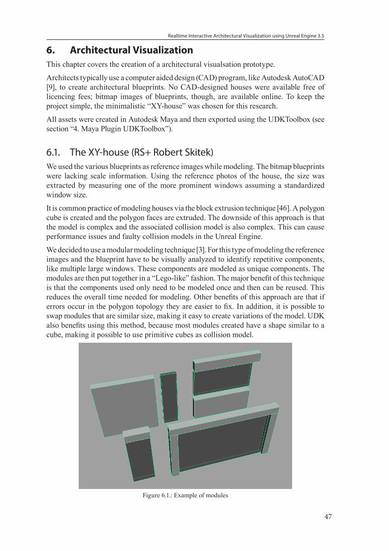
Realtime Interactive Architectural Visualization using Unreal Engine 3.5
47
6. Architectural Visualization This chapter covers the creation of a architectural visualsation prototype.
Architects typically use a computer aided design (CAD) program, like Autodesk AutoCAD [9], to create architectural blueprints. No CAD-designed houses were available free of licencing fees; bitmap images of blueprints, though, are available online. To keep the project simple, the minimalistic “XY-house” was chosen for this research.
All assets were created in Autodesk Maya and then exported using the UDKToolbox (see section “4. Maya Plugin UDKToolbox”).
6.1. The XY-house (RS+ Robert Skitek)We used the various blueprints as reference images while modeling. The bitmap blueprints were lacking scale information. Using the reference photos of the house, the size was extracted by measuring one of the more prominent windows assuming a standardized window size.
It is common practice of modeling houses via the block extrusion technique [46]. A polygon cube is created and the polygon faces are extruded. The downside of this approach is that the model is complex and the associated collision model is also complex. This can cause performance issues and faulty collision models in the Unreal Engine.
We decided to use a modular modeling technique [3]. For this type of modeling the reference images and the blueprint have to be visually analyzed to identify repetitive components, like multiple large windows. These components are modeled as unique components. The modules are then put together in a “Lego-like” fashion. The major benefit of this technique is that the components used only need to be modeled once and then can be reused. This reduces the overall time needed for modeling. Other benefits of this approach are that if errors occur in the polygon topology they are easier to fix. In addition, it is possible to swap modules that are similar size, making it easy to create variations of the model. UDK also benefits using this method, because most modules created have a shape similar to a cube, making it possible to use primitive cubes as collision model.
Figure 6.1.: Example of modules
Realtime Interactive Architectural Visualization using Unreal Engine 3.5
48
Based on the reference images, we created basic models for the living room area to make it easier for the user to perceive the scale of the building.
The materials used for these objects are described in “5.2. Materials” on page 31.
Figure 6.2.: Completed XY-house
6.2. Interior Lighting Models of lamps were created and the GUI was extended to support interactions with those lamps.
6.2.1. Lamp Models
We created three different types of lamps, a large ball shaped lamp, a flat lamp, and a chandelier.
The design of each of lamps followed the same principle. A mesh for the entire lamp was created. To be able to make the lampshade glow the mesh was then separated into a “lampshade” and “non-lampshade” part making it easier to apply materials.
An alternative process to have similar control of the material would be using texture maps, however, for each lamp a unique texture map would have had to be created and the material network for each lamp recreated.
The lamp model has no collision model due to the fact that lamps are hanging from the ceiling and usually do not obstruct walking in the room.
In UDK the lamps were placed and accompanying “ToggleableStaticLight” actors and “Trigger” actors were added for direct interaction.
6.2.2. GUI Extension
The framework GUI was extended to support controls for the individual lights as well as an all lights on/off switch. In addition, several controls were added to display light combinations.
Realtime Interactive Architectural Visualization using Unreal Engine 3.5
49
In Flash two sections “Light Combinations” and “Lights” were added. The buttons controlling the lights were organized in rows according to floor.
Kismet Script
When toggling the lamp the light and the material have to turn off or on. To be able to control the material effect individually, for each lamp a unique material instance of the glow material was created and applied to each lamp. The lamp trigger activates when using the “Use”-key (“E”) or the menu.
The glow property of the material is controlled by a Matinee sequence. To simulate incandescent light bulbs a zero-second animation was used to toggle the glow property on or off.
However, the Matinee sequence could also be used to animate the glow property and the light intensity in synchronization to simulate the flickering/slow start of compact fluorescent lamps.
Support for “all lights on/off” and light combinations adds complexity to the Kismet script. These events have to connect to all individual light sequences.
To simplify the script we introduced a “Switch” node. The “Switch” node takes an input and maps it to one of several outputs depending on its counter. By disabling the counter and manually setting the index, the node can be used as an array node.
Using an “int counter” node all lights can be turned on/off; by including simple conditions to the script, light combinations can be set.
The switch node is useful to preserve existing light combinations when more lights are added.
6.3. Frame RateWe measured the performance of the system in three environments. The average frame rate was:
No environment 80fps
City environment 70fps
Nature environment 14fps
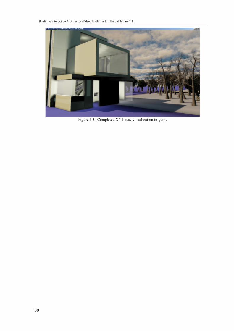
Realtime Interactive Architectural Visualization using Unreal Engine 3.5
50
Figure 6.3.: Completed XY-house visualization in-game
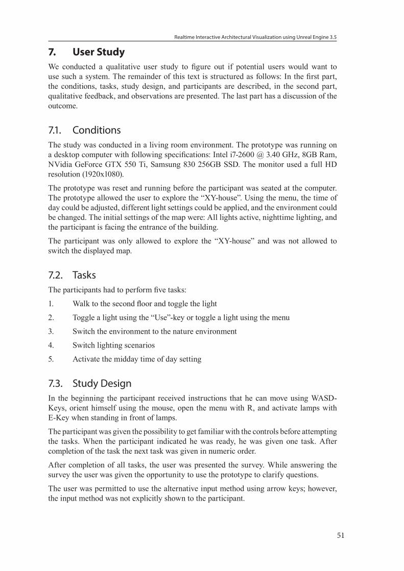
Realtime Interactive Architectural Visualization using Unreal Engine 3.5
51
7. User StudyWe conducted a qualitative user study to figure out if potential users would want to use such a system. The remainder of this text is structured as follows: In the first part, the conditions, tasks, study design, and participants are described, in the second part, qualitative feedback, and observations are presented. The last part has a discussion of the outcome.
7.1. ConditionsThe study was conducted in a living room environment. The prototype was running on a desktop computer with following specifications: Intel i7-2600 @ 3.40 GHz, 8GB Ram, NVidia GeForce GTX 550 Ti, Samsung 830 256GB SSD. The monitor used a full HD resolution (1920x1080).
The prototype was reset and running before the participant was seated at the computer. The prototype allowed the user to explore the “XY-house”. Using the menu, the time of day could be adjusted, different light settings could be applied, and the environment could be changed. The initial settings of the map were: All lights active, nighttime lighting, and the participant is facing the entrance of the building.
The participant was only allowed to explore the “XY-house” and was not allowed to switch the displayed map.
7.2. TasksThe participants had to perform five tasks:
1. Walk to the second floor and toggle the light
2. Toggle a light using the “Use”-key or toggle a light using the menu
3. Switch the environment to the nature environment
4. Switch lighting scenarios
5. Activate the midday time of day setting
7.3. Study DesignIn the beginning the participant received instructions that he can move using WASD-Keys, orient himself using the mouse, open the menu with R, and activate lamps with E-Key when standing in front of lamps.
The participant was given the possibility to get familiar with the controls before attempting the tasks. When the participant indicated he was ready, he was given one task. After completion of the task the next task was given in numeric order.
After completion of all tasks, the user was presented the survey. While answering the survey the user was given the opportunity to use the prototype to clarify questions.
The user was permitted to use the alternative input method using arrow keys; however, the input method was not explicitly shown to the participant.
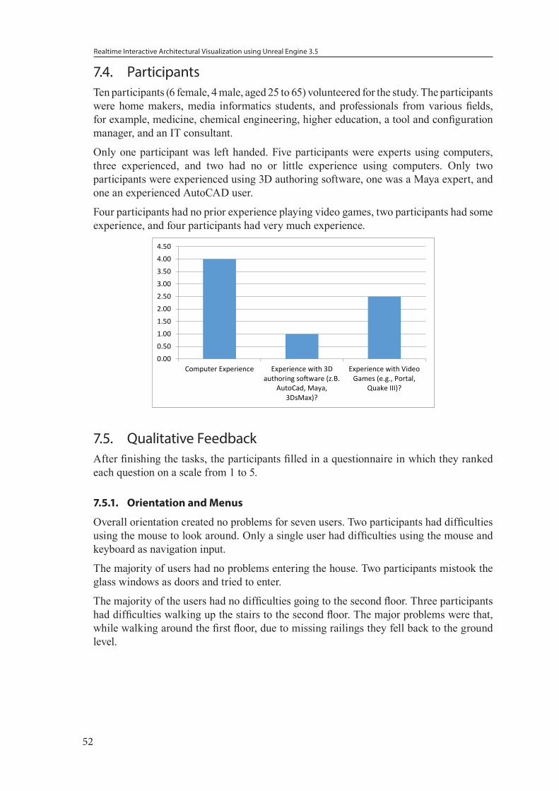
Realtime Interactive Architectural Visualization using Unreal Engine 3.5
52
7.4. ParticipantsTen participants (6 female, 4 male, aged 25 to 65) volunteered for the study. The participants were home makers, media informatics students, and professionals from various fields, for example, medicine, chemical engineering, higher education, a tool and configuration manager, and an IT consultant.
Only one participant was left handed. Five participants were experts using computers, three experienced, and two had no or little experience using computers. Only two participants were experienced using 3D authoring software, one was a Maya expert, and one an experienced AutoCAD user.
Four participants had no prior experience playing video games, two participants had some experience, and four participants had very much experience.
0.00
0.50
1.00
1.50
2.00
2.50
3.00
3.50
4.00
4.50
Computer Experience Experience with 3Dauthoring software (z.B.
AutoCad, Maya,3DsMax)?
Experience with VideoGames (e.g., Portal,
Quake III)?
0.00
0.50
1.00
1.50
2.00
2.50
3.00
3.50
4.00
4.50
Computer Experience Experience with 3Dauthoring software (z.B.
AutoCad, Maya,3DsMax)?
Experience with VideoGames (e.g., Portal,
Quake III)?
7.5. Qualitative FeedbackAfter finishing the tasks, the participants filled in a questionnaire in which they ranked each question on a scale from 1 to 5.
7.5.1. Orientation and Menus
Overall orientation created no problems for seven users. Two participants had difficulties using the mouse to look around. Only a single user had difficulties using the mouse and keyboard as navigation input.
The majority of users had no problems entering the house. Two participants mistook the glass windows as doors and tried to enter.
The majority of the users had no difficulties going to the second floor. Three participants had difficulties walking up the stairs to the second floor. The major problems were that, while walking around the first floor, due to missing railings they fell back to the ground level.
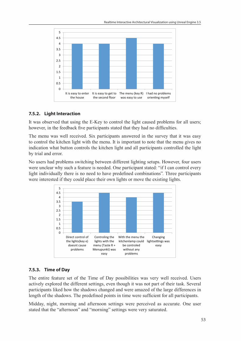
Realtime Interactive Architectural Visualization using Unreal Engine 3.5
53
0
0.5
1
1.5
2
2.5
3
3.5
4
4.5
5
It is easy to enterthe house
It is easy to get tothe second floor
The menu (key R)was easy to use
I had no problemsorienting myself
7.5.2. Light Interaction
It was observed that using the E-Key to control the light caused problems for all users; however, in the feedback five participants stated that they had no difficulties.
The menu was well received. Six participants answered in the survey that it was easy to control the kitchen light with the menu. It is important to note that the menu gives no indication what button controls the kitchen light and all participants controlled the light by trial and error.
No users had problems switching between different lighting setups. However, four users were unclear why such a feature is needed. One participant stated: “if I can control every light individually there is no need to have predefined combinations”. Three participants were interested if they could place their own lights or move the existing lights.
00.5
11.5
22.5
33.5
44.5
5
Direct control ofthe lights(key e)
doesnt causeproblems
Controling thelights with the
menu (Taste R +Menupunkt) was
easy
With the menu thekitchenlamp could
be controledwithout any
problems
Changinglightsettings was
easy
7.5.3. Time of Day
The entire feature set of the Time of Day possibilities was very well received. Users actively explored the different settings, even though it was not part of their task. Several participants liked how the shadows changed and were amazed of the large differences in length of the shadows. The predefined points in time were sufficient for all participants.
Midday, night, morning and afternoon settings were perceived as accurate. One user stated that the “afternoon” and “morning” settings were very saturated.
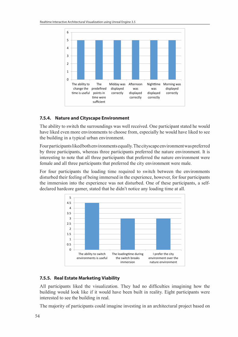
Realtime Interactive Architectural Visualization using Unreal Engine 3.5
54
0
1
2
3
4
5
6
The ability tochange thetime is useful
Thepredefined
points intime weresufficient
Midday wasdisplayedcorrectly
Afternoonwas
displayedcorrectly
Nighttimewas
displayedcorrectly
Morning wasdisplayedcorrectly
7.5.4. Nature and Cityscape Environment
The ability to switch the surroundings was well received. One participant stated he would have liked even more environments to choose from, especially he would have liked to see the building in a typical urban environment.
Four participants liked both environments equally. The cityscape environment was preferred by three participants, whereas three participants preferred the nature environment. It is interesting to note that all three participants that preferred the nature environment were female and all three participants that preferred the city environment were male.
For four participants the loading time required to switch between the environments disturbed their feeling of being immersed in the experience, however, for four participants the immersion into the experience was not disturbed. One of these participants, a self-declared hardcore gamer, stated that he didn’t notice any loading time at all.
00.5
11.5
22.5
33.5
44.5
5
The ability to switchenvironments is useful
The loadingtime duringthe switch breaks
immersion
I prefer the cityenvironment over thenature environment
7.5.5. Real Estate Marketing Viability
All participants liked the visualization. They had no difficulties imagining how the building would look like if it would have been built in reality. Eight participants were interested to see the building in real.
The majority of participants could imagine investing in an architectural project based on
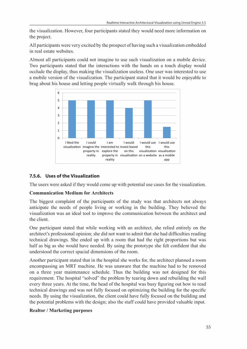
Realtime Interactive Architectural Visualization using Unreal Engine 3.5
55
the visualization. However, four participants stated they would need more information on the project.
All participants were very excited by the prospect of having such a visualization embedded in real estate websites.
Almost all participants could not imagine to use such visualization on a mobile device. Two participants stated that the interactions with the hands on a touch display would occlude the display, thus making the visualization useless. One user was interested to use a mobile version of the visualization. The participant stated that it would be enjoyable to brag about his house and letting people virtually walk through his house.
0
1
2
3
4
5
6
I liked thevisualization
I couldimagine theproperty in
reality
I aminterested toexplore theproperty in
reality
I wouldinvest based
on thisvisualization
I would usethis
visualizationon a website
I would usethis
visualizationas a mobile
app
7.5.6. Uses of the Visualization
The users were asked if they would come up with potential use cases for the visualization.
Communication Medium for Architects
The biggest complaint of the participants of the study was that architects not always anticipate the needs of people living or working in the building. They believed the visualization was an ideal tool to improve the communication between the architect and the client.
One participant stated that while working with an architect, she relied entirely on the architect’s professional opinion; she did not want to admit that she had difficulties reading technical drawings. She ended up with a room that had the right proportions but was half as big as she would have needed. By using the prototype she felt confident that she understood the correct spacial dimensions of the room.
Another participant stated that in the hospital she works for, the architect planned a room encompassing an MRT machine. He was unaware that the machine had to be removed on a three year maintenance schedule. Thus the building was not designed for this requirement. The hospital “solved” the problem by tearing down and rebuilding the wall every three years. At the time, the head of the hospital was busy figuring out how to read technical drawings and was not fully focused on optimizing the building for the specific needs. By using the visualization, the client could have fully focused on the building and the potential problems with the design; also the staff could have provided valuable input.
Realtor / Marketing purposes
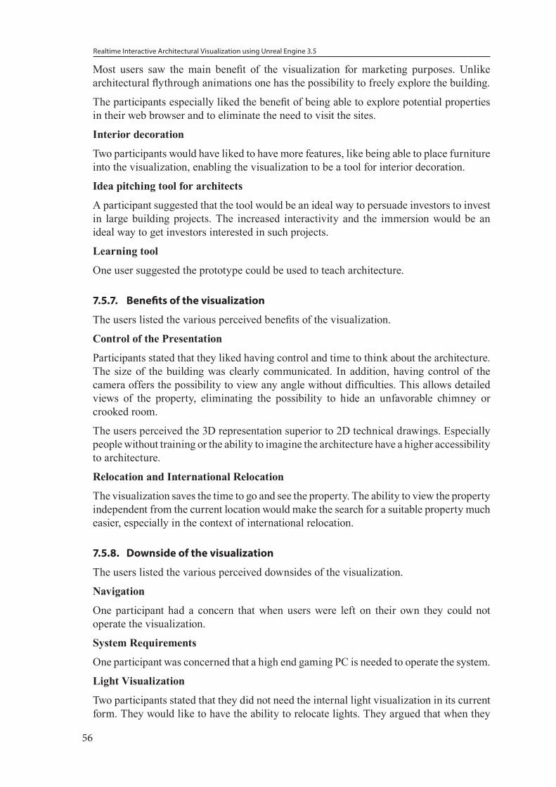
Realtime Interactive Architectural Visualization using Unreal Engine 3.5
56
Most users saw the main benefit of the visualization for marketing purposes. Unlike architectural flythrough animations one has the possibility to freely explore the building.
The participants especially liked the benefit of being able to explore potential properties in their web browser and to eliminate the need to visit the sites.
Interior decoration
Two participants would have liked to have more features, like being able to place furniture into the visualization, enabling the visualization to be a tool for interior decoration.
Idea pitching tool for architects
A participant suggested that the tool would be an ideal way to persuade investors to invest in large building projects. The increased interactivity and the immersion would be an ideal way to get investors interested in such projects.
Learning tool
One user suggested the prototype could be used to teach architecture.
7.5.7. Benefits of the visualization
The users listed the various perceived benefits of the visualization.
Control of the Presentation
Participants stated that they liked having control and time to think about the architecture. The size of the building was clearly communicated. In addition, having control of the camera offers the possibility to view any angle without difficulties. This allows detailed views of the property, eliminating the possibility to hide an unfavorable chimney or crooked room.
The users perceived the 3D representation superior to 2D technical drawings. Especially people without training or the ability to imagine the architecture have a higher accessibility to architecture.
Relocation and International Relocation
The visualization saves the time to go and see the property. The ability to view the property independent from the current location would make the search for a suitable property much easier, especially in the context of international relocation.
7.5.8. Downside of the visualization
The users listed the various perceived downsides of the visualization.
Navigation
One participant had a concern that when users were left on their own they could not operate the visualization.
System Requirements
One participant was concerned that a high end gaming PC is needed to operate the system.
Light Visualization
Two participants stated that they did not need the internal light visualization in its current form. They would like to have the ability to relocate lights. They argued that when they
Realtime Interactive Architectural Visualization using Unreal Engine 3.5
57
would move into the house they would put in different types of lamps.
Surroundings
Two participants stated that the visualization is not connected to the actual surroundings making the displayed surroundings feel too abstract and unnatural.
7.5.9. General Feedback
The participants were giving the option to give general feedback.
Season Visualization
One participant suggested a feature to visualize seasons to even more emphasize how the building would look throuout the year.
Glass Material
One participant stated that he did not like the reflections of the glass material; he would have expected to see himself in the glass when walking near the glass window. This way he had no way to distinguish between an empty space and a window.
Usability
A participant had problems activating/deactivating the lights with the E-Key. The user suggested adding a targeting cross hair that indicates if the use function is available or not.
7.6. ObservationsHere are some observations on how the participants were using the prototype.
7.6.1. WASD input method
Seven participants utilized the WASD controls without having any explicit demonstration or information from the study conductor. The remaining 3 participants had never before played computer games and needed an introduction to the controls.
Performing actions using the E-Key was familiar due to similar use in video games. On the other hand, opening the menu with the R-Key was unfamiliar to all participants and had to be explained. Users expected to be able to open the menu using the escape key. No participant utilized the arrow keys for navigation.
7.6.2. Personal
All participants reacted to the prototype in a rather personal way; they immediatly drew comparisions with their current living arrangements or work environment.
7.6.3. Age
Participants of age 60+ did not see any practical use for the prototype. It was a nice gimmick without any practical use. However, when asked about their current living situation it was revealed that they lived in their home for more than 30 years and did not have any intension of relocating,
Participants of age 40-50, were housewives, primarily wanted to use the prototype for interior planning.
Realtime Interactive Architectural Visualization using Unreal Engine 3.5
58
Students of age 20-30 strongly wanted to see website integration of the prototype.
7.7. DiscussionThe study shows, even though the sample size is small, a clear tendency that the users were very engaged in the visualization. None of the participants had major difficulties using the system. Minor usability features could be added to create a smoother user experience.
The viewers were neither aware of the artificial nature of the sky visualization nor of the lighting design aspects. Average users take lighting for granted. The users were not aware of the lighting system specifically designed for architectural light visualization.
The biggest influence on the perception of the visualization appeared to be dependent on the plan to relocate or invest in a property. If the user is happy with his current living arrangement and has no interest to invest, the viewer has no interest in the visualization.
The prototype gives the user the ability to control the visualization and view the building from any angle in different times of day. This tool would make the visualization a powerful marketing tool to appeal to the average user.
Realtime Interactive Architectural Visualization using Unreal Engine 3.5
59
8. SummaryThe project analyzed the capabilities of using Unreal game technology to be applied in the field of architectural visualization. Maya was used to convert architectural data into UDK assets. This required the creation of a plugin to streamline the workflow. The aim was to lower the entry barrier for professionals and increase efficiency, as well as allowing rapid prototyping of 3D visualizations.
Game engine development requires knowledge of different fields: 3D modeling (hard surface modeling, texturing, normal mapping), UDK features (Kismet Visual Scripting, Matinee Animation, UnrealScript), and Scaleform (Flash, ActionScript 3.0).
A modular UDK architectural visualization framework was created with following features: configuration of the UDK to support architectural visualization, exchangeable environments, time of day visualization, interior lighting, basic architectural materials, and interface for architectural interaction. The modular nature of the framework allows components of the framework to be easily updated and extended. The core of the framework can be used as the foundation for different types of visualizations not limited to architectural visualization.
Using the Maya plugin drastically reduces the time needed to create 3D assets; at the same time 3D artists require no explicit knowledge of the FBX workflow and the plugin is self-explanatory. In combination with the framework this reduces the entry barrier to work with UDK. Newcomers to the systems only require basic knowledge of 3D modeling, UDK, and optionally Flash, to create visualizations.
The framework was used to represent the XY-house. The lighting features available in the UDK were further explored to be able to provide interior lighting. A qualitative study was performed where users could interact with the visualization.
The visualization was positively received. The participants were pleased to see a 3D visualized building instead of having to deal with technical drawings. They felt that this would be a good communication medium to confidently provide their ideas to the architect.
8.1. Comments on the Lighting SystemWe tried to focus on the specialized needs of architectural light simulation. One major aspect is the accurate representation of sunlight. For this there are two considerations: the light source is constantly moving, and the light changes its color. This requires the interior bounce light to be updated dynamically. Full dynamic lights are needed to fulfill these requirements. UDK’s partially dynamic lights do not calculate bounce light. Lighting artists overcome this problem by introducing additional light sources that visualize bounce light [75]. However, this technique only creates an approximation and is not based on a simulation model used for architectural light planning. Another important aspect is the support of IES light files as previously mentioned in (see section “5.3.4. Photometric Data”).
Due to the restrictions of the freely available UDK, it cannot be extended with external code to support a full dynamic lighting model. However, the next release of Unreal Engine 4 will support spherical harmonics [57] that are used for dynamic indirect light calculations. At this time, Epic Games has not provided any indication, that it will support the use of IES files.
Realtime Interactive Architectural Visualization using Unreal Engine 3.5
60
As alternative to UDK it is possible to consider open source engines, like GarageGames Torque 3D [35]. At this time the engines do not support full dynamic lights, and other features available in UDK are missing. However, they provide open access to the engine enabling programmers to implement missing features.
8.2. Future WorkUDK is a gaming platform that can be used for serious research [36]. Already now in the field of military and medical research game technology is used for training purposes.
The prototype framework we created covers the basic features needed for architectural visualization. More advanced features could be added to the system, like a weather system, or adding animated characters and vehicles to create a living city visualization. The time of day feature could be extended to a time of year visualization allowing the user to switch between various seasons of the year.
UDK has the possiblity to utilize different types of input devices. For example, mobile touch screen devices could be used to navigate in 3D environments, or tangible input devices, like “Tangible Blocks” [51], could be used to interact with the 3D environment.
Mozilla and Epic Games has been announced that UDK is being ported to WebGL to enable 3D experiences on the Web [49]. These features make it possible to create browser integrated architectural marketing tools.
The visualization itself does not have to be limited to display-only static buildings; it could be extended to support the visualization of development steps made over the years. This kind of visualization helps people pre-visualize renovations. This would be very useful, for example, for large government projects, so that the public could see how it will change the environment and vocalize their concerns.
The visualization would not have to be limited to a single user experience. By using UDK’s multiplayer features it would be possible to create a collaborative workspace, where the user could directly interact with other people.
It would be interestesting to investigate dual screen interactions found in modern consoles, like the Nintendo Wii U [50] that has an integrated touchscreen in its controller. The Microsoft XBox supports SmartGlass [48], a system that allows mobile devices to serve as second screen and remote controller. UDKs broad range of cross-plattform and mobile device support would allow the rapid development of interaction prototypes for these consoles.
Realtime Interactive Architectural Visualization using Unreal Engine 3.5
61
9. References
[1] 1. Fritsch D, Kada M. Visualization using game engines. 2004.
[2] 3D Cluny III. 1. Dec. 2012. <http://strabic.fr/Cluny-III-en-3D.html>
[3] 3D Motive, Modular Building Workflow. 21. Mar. 2013. <https://www.3dmotive.com/f101001>
[4] 3ds Max 8 Architectural Visualization, Brian L.Smith
[5] A-HSN. (n.d.). Azuma House by Tadao Ando. 1. Mar. 2013, <http://courtyard-house.blogspot.de/2010/06/azuma-house-by-tadao-ando.html>
[6] Adobe After Effects, 20. Mar. 2013. <http://www.adobe.com/products/aftereffects.html>
[7] Adobe Flash, 20. Mar. 2013. <http://www.adobe.com/products/flash.html>
[8] Amresh, A., & Okita, A. (2010). Unreal Game Development. Natick: A K Peters, Ltd.
[9] Autodesk, I. (n.d.). AutoCAD-Funktionen. May 28, 2012, <http://www.autodesk.de/adsk/servlet/pc/index?siteID=403786&id=14564212>
[10] Autodesk. 3D Data Interchange Technology. 20. Mar. 2013. <http://usa.autodesk.com/fbx/>
[11] Autodesk 3DsMax, 20. Mar. 2013. <http://usa.autodesk.com/3ds-max/>
[12] Autodesk Ecotect Analysis, 27. Mar. 2013. <http://usa.autodesk.com/ecotect-analysis/>
[13] Autodesk Ecotect Analysis Visualize sustainable design <http://images.autodesk.com/adsk/files/autodesk_ecotect_analysis_2011_brochure.pdf>
[14] Autodesk Software Maya. 1. Oct. 2012. <http://usa.autodesk.com/maya/>
[15] Berger, Warren. “Future Quest: Go Where No Real Estate Company Has Gone Before.” Real Estate Today. January 1994
[16] Busby, J., Parrish, Z. & Wilson, J., Mastering Unreal Technology Volume I: Basic Level Design Concepts with Unreal Engine 3
[17] Busby, J., Parrish, Z. & Wilson, J., Mastering Unreal Technology Volume II: Advanced Level Design Concepts with Unreal Engine 3
[18] Chen L, Architectural Visualization. 2004.
[19] Christian Père, Sébastien Faucher, Cluny : de la gestion de données à la réalité augmentée, 2007
[20] Circus Productions, CIRKUS’ ANIMATION ABC – HOW IT WORKS… 1. March 2013 <http://cirkus.co.nz/blog/2010/02/cirkus-animation-abc-how-it-works/>
[21] Computer Animation: Expert Advice on Breaking into the buisiness
[22] Creating Customer Utopia Through Your Customer Experience, 27. Mar. 2013. <http://www.ravetopia.com/triggering-your-word-of-marketing-strategy-through-your-customer-experience>
Realtime Interactive Architectural Visualization using Unreal Engine 3.5
62
[23] CryTek, Official CryEngine 3 Free SDK Documentation, 20. Oct. 2012. <http://freesdk.crydev.net/dashboard.action>
[24] Crytek, Visuals, 20. Mar. 2013. <http://www.myCryEngine.com/index.php?conid=8>
[25] Crytek. Visuals. 1.Oct. 2012. <http://myCryEngine.com/index.php?conid=8>
[26] Derakhshani, D., (2012), Introducing to Maya 2013, John Wiley & Sons
[27] Digital Tutors, CG 101, 2012
[28] Ecotect: Shadows & Sunlight Hours, 27. Mar. 2013. <http://sustainabilityworkshop.autodesk.com/buildings/ecotect-shadows-sunlight-hours>
[29] Epic Games, Introducing Unreal Engine 4, 5 Dec. 2012. <http://www.unrealengine.com/unreal_engine_4/>
[30] Epic Games, Introduction to UDK Training Videos, 2007
[31] Epic Games, Landscape Creation, 20. Mar. 2013. <http://udn.epicgames.com/Three/LandscapeCreating.html>
[32] Epic Games. Epic Games Announces the Unreal Development Kit Powered by Unreal Engine. 1.10.2012 <http://www.udk.com/launch>
[33] Epic Games. FBX workflow. 1. Oct. 2012. <http://udn.epicgames.com/Three/FBXStaticMeshPipeline.html>
[34] Escape Studios, VFX Career Bible, 2013
[35] GarageGames. Torque 3D. 20. Mar. 2013. <http://www.garagegames.com/products/torque-3d>
[36] Holt T., Games get serious, Computer Games for Visualization and More. 20. Mar. 2013. < http://dusk.geo.orst.edu/Pickup/holt_serious_games.pdf>
[37] IBM France, Artway Editions, Cluny : ou, “mémoires de pierres”, 1993, VHS video
[38] idSoft. Get Quake 3 engine open source. 11. Nov. 2012. <http://ioquake3.org/get-it/>
[39] IGN Entertainment. Unreal Engine 3: Official Samaritian Demo. 7. Oct. 2012. <http://www.youtube.com/watch?v=RSXyztq_0uM>
[40] Interview Curtis Edwards
[41] Interview TUM Architekturinformatik
[42] iRay, Speed, Simplicity, Quality
[43] Jacobsen, Jeffrey, Hwang, Zimmy, Unreal Tournament for immersive Interactive Theater, 2002
[44] Joshua Buck, jbUDK Tools 20. Mar. 2013. <http://www.cgartistry.com/code.html>
[45] Julio Juarez, UDK Sun
[46] Karan Shah, Create A 3D Floor Plan Model From An Architectural Schematic In Blender, 2012, 20.Mar. 2013, < http://cg.tutsplus.com/tutorials/blender/create-a-3d-floor-plan-model-from-an-architectural-schematic-in-blender/>
Realtime Interactive Architectural Visualization using Unreal Engine 3.5
63
[47] LMU-Munich, LFE Medieninformatik, “Projektkompetenz Multimedia: Unreal Development”, Sommersemester 2012, <http://www.medien.ifi.lmu.de/lehre/ss12/pkmu/>
[48] Microsoft XBox SmartGlass, 27. Mar. 2013. <http://www.xbox.com/en-US/smartglass>
[49] Mozilla is Unlocking the Power of the Web as a Platform for Gaming, 27. Mar. 2013. <http://blog.mozilla.org/blog/2013/03/27/mozilla-is-unlocking-the-power-of-the-web-as-a-platform-for-gaming/>
[50] Nintendo Wii U, 27. Mar. 2013. < http://www.nintendo.de/Wii-U/Wii-U-344102.html>
[51] P.Baudisch, Lumino: Tangible Blocks for Tabletop Computers Based on Glass Fiber Bundles
[52] Papam Studios. UDK Study: Day cycle Simulation, Work in Progress. 1. Nov. 2012 <http://www.papamstudios.com/projects.html>
[53] Perforce, Software Version Management, 20. Mar. 2013. <http://www.perforce.com/>
[54] Preview of Autodesk Ecotect Analysis 2010, 27. Mar. 2013. <http://www.youtube.com/watch?v=BKZ35xh4ofw>
[55] Prof. Dr. Hermann Parzinger, Neuordnung der Kunstsammlungen der Stiftung Preußischer Kulturbesitz, 30. Nov. 2012. <http://www.rotary1940.de/berlin/00_aktuell/parzinger_kunstsammlung.php?mydesign=tuerkis&client=berlin&client_wID=888&print=true>
[56] PublicVR, CaveUT. 5. Dec 2012. http://publicvr.org/html/pro_caveut.html
[57] Ramamoorthi, Ravi, and Pat Hanrahan. “An efficient representation for irradiance environment maps.” Proceedings of the 28th annual conference on Computer graphics and interactive techniques. ACM, 2001.
[58] Recoil Games. Rochard Screenshot. 21. Mar. 2013. <http://www.rochardthegame.com/en/screenshots/>
[59] Rman197, Extract Google Earth models to 3ds max tutorial, 20. Mar. 2013. <http://www.youtube.com/watch?v=18QbZyuy2JY>
[60] Rodrigo Zacharias, Decorated Suite, 1. Dec 2012. <http://www.cgarchitect.com/2012/12/decorated-suite>
[61] Roman Lut, 3D Ripper DX , 20. Mar. 2013. <http://www.deep-shadows.com/hax/3DRipperDX.htm>
[62] RTT AG, System requirements and installation. 2012
[63] Team Black Mesa Modification. About the Mod. 11. Nov 2012. <http://wiki.blackmesasource.com/Black_Mesa:About_the_Mod>
[64] The Foundry Nuke, 27. Mar. 2013 <www.thefoundry.co.uk/products/nuke/>
[65] Tiffany Ortis, Is Solar Design a Straitjacket for Architecture?
[66] Ubisoft Farcry 3, 20. Oct. 2012. <http://myCryEngine.com/index.php?conid=69&id=18>
Realtime Interactive Architectural Visualization using Unreal Engine 3.5
64
[67] UDK Documentation, ActorX Plugin, http://udn.epicgames.com/Two/ActorX.html
[68] UDK Documentation, Level optimization guide, 20. Oct. 2012. <http://udn.epicgames.com/Three/LevelOptimization.html>
[69] Unity Technologies. Unrivaled Power Meets Unparalleled Productivity. 1. Oct. 2012. <http://unity3d.com/unity/engine/>
[70] Unreal Engine 4 - GT.TV Exclusive Development Walkthrough <http://www.youtube.com/watch?v=MOvfn1p92_8>
[71] UnrealWiki, Legacy:T3D File. 20. Mar. 2013. <http://wiki.beyondunreal.com/Legacy:T3D_File>
[72] Unreal Wiki, Legacy:Unreal Unit, 20. 0ct. 2012, <http://wiki.beyondunreal.com/Legacy:Unreal_Unit>
[73] Valve, Half-Life 2 raising the bar, Prima Games, Roseville 2004
[74] Viktor Fretyan, Lighting La Salle - Indoor Illumination Tutorial Series
[75] Wissler V, Illuminated Pixel, 2012, Cengage Learning
[76] World of Level Design. UDK: 18 Important Principles for Creating and Using Lightmaps in UDK (Lightmapping Basics). 1.Oct. 2012. <http://www.worldofleveldesign.com/categories/udk/udk-lightmaps-01-basics-and-important-principles-for-creating-using-lightmaps.php>
[77] Yanni Hajioannou, 2013, 20. Mar. 2013. <http://gamedev.tutsplus.com/articles/glossary/quick-tip-what-is-a-normal-map/>
[78]

Realtime Interactive Architectural Visualization using Unreal Engine 3.5
65
10. Contents of attached DVD/01 _ References
/02 _ UDKToolBoxPlugin
/03 _ MayaModels
/04 _ UDKFramework
/05 _ Antrittsvortrag
/06 _ Abschlussvortrag
/07 _ Thesis
UDKInstall-Architectura.exe (final visualization)
Interactive _ Architectural _ Visualization.pdf (this document as pdf-file)
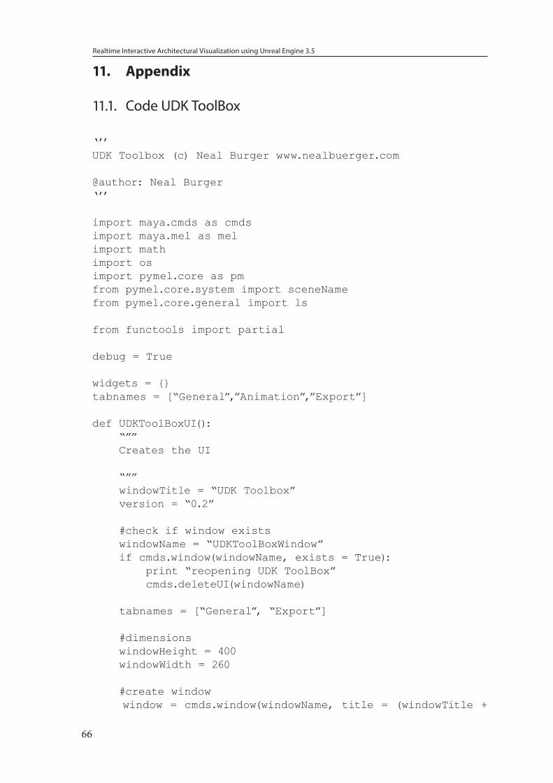
Realtime Interactive Architectural Visualization using Unreal Engine 3.5
66
11. Appendix
11.1. Code UDK ToolBox
‘’’UDK Toolbox (c) Neal Burger www.nealbuerger.com
@author: Neal Burger‘’’
import maya.cmds as cmdsimport maya.mel as melimport mathimport osimport pymel.core as pmfrom pymel.core.system import sceneNamefrom pymel.core.general import ls
from functools import partial
debug = True
widgets = {}tabnames = [“General”,”Animation”,”Export”]
def UDKToolBoxUI(): “”” Creates the UI “”” windowTitle = “UDK Toolbox” version = “0.2” #check if window exists windowName = “UDKToolBoxWindow” if cmds.window(windowName, exists = True): print “reopening UDK ToolBox” cmds.deleteUI(windowName) tabnames = [“General”, “Export”] #dimensions windowHeight = 400 windowWidth = 260 #create window window = cmds.window(windowName, title = (windowTitle +
Realtime Interactive Architectural Visualization using Unreal Engine 3.5
67
“ “ + version), wh = (windowWidth, windowHeight), sizeable = False, mbv=True, mnb = True, mxb=False, menuBar = True) cmds.menu( label=’?’, helpMenu=True) cmds.menuItem(“About”) cmds.columnLayout(w= 255, h = 350) widgets[“tabLayout”] = cmds.tabLayout(imw = 5, imh = 5) for item in tabnames: widgets[(item + “ _ tab”)] = cmds.columnLayout(w = 254, h = 350, parent = widgets[“tabLayout”]) cmds.tabLayout(widgets[“tabLayout”], edit = True, tabLabel = (widgets[(item + “ _ tab”)], item)) createTab(item) cmds.showWindow(window) def createTab(name): “”” Creates a Tab for the UI Call the function from UDKToolBox() name: Name of the Tab “”” categoryWidth = 250 threeBtnWidth = 80 oneBtnWidth = 3*threeBtnWidth btnHeight = 30 tabname = (name + “ _ tab”) if name == tabnames[0]: categoriesGeneral = [“Grid”, “References”, “Collision”, “UV Layout”, “Misc”] for item in categoriesGeneral: widgets[(tabname + item)] = cmds.frameLayout(label = item, collapsable = True, parent = widgets[tabname]) parent = cmds.rowColumnLayout(nr = 1, w=categoryWidth, p = widgets[(tabname + item)]) if item == categoriesGeneral[0]: widgets[“grid _ btn”] = cmds.button( w= threeBtnWidth, h = btnHeight, c= toggleGridSnap, p = parent) toggleGridSnap(“init”) cmds.button( w=threeBtnWidth, h=btnHeight, label=”UDK Grid”, c=partial(changeGridSettings,”udk”), p = parent) cmds.button( w=threeBtnWidth, h=btnHeight, label=”Default Grid”, c=partial(changeGridSettings,”default”), p = parent) if item == categoriesGeneral[1]:
Realtime Interactive Architectural Visualization using Unreal Engine 3.5
68
parent = cmds.rowColumnLayout(nr = 5, w=categoryWidth, p = widgets[(tabname + item)]) widgets[“references _ import”] = “references _import” cmds.optionMenu( widgets[“references _ import”], w=categoryWidth, label=”Choose a Reference: “, p = parent) populateReferenceImportMenu() cmds.button( h=btnHeight, w = oneBtnWidth, label=”Import”, c = referencesImport, p = parent) cmds.separator(h=10, p = parent) cmds.rowColumnLayout( nr=1, cs=[(1,2), (3,3), (5,3)], p= parent ) cmds.text(w=10, label=”W”) widgets[“references _ wField”] = “references _wField” cmds.floatField( widgets[“references _ wField”], w=40, min=0, v=4.0, pre=1 ) cmds.text(w=10, label=”H”) widgets[“references _ hField”] = “references _hField” cmds.floatField( widgets[“references _ hField”], w=40, min=0, v=6.0, pre=1 ) cmds.text(w=10, label=”D”) widgets[“references _ dField”] = “references _dField” cmds.floatField( widgets[“references _ dField”], w=40, min=0, v=4.0, pre=1 ) cmds.button( h=btnHeight, w=oneBtnWidth, label=”Cube Reference(cm)”, c = referenceCube, p = parent) if item == categoriesGeneral[2]: cmds.button( w=threeBtnWidth, h=btnHeight, label=”Box”, c=partial(createCollision,”box”), p = parent) cmds.button( w=threeBtnWidth, h=btnHeight, label=”Sphere”, c=partial(createCollision,”sphere”), p = parent) cmds.button( w=threeBtnWidth, h=btnHeight, label=”Duplicate”, c=partial(createCollision,”duplicate”), p = parent) if item == categoriesGeneral[3]: cmds.button( w=threeBtnWidth, h=btnHeight, label=”UV Editor”, c=uv _ openUVEditor, p = parent) cmds.button( w=threeBtnWidth, h=btnHeight, label=”Auto Map”, c=uv _ autoMap, p = parent) cmds.button( w=threeBtnWidth, h=btnHeight, label=”Light Map”, c=uv _ lightMap, p = parent) if item == categoriesGeneral[4]:
Realtime Interactive Architectural Visualization using Unreal Engine 3.5
69
cmds.button( w=threeBtnWidth, h=btnHeight, label=”Name Materials”, c=applyTextureNaming, p = parent) cmds.button( w=threeBtnWidth, h=btnHeight, label=”Del CH /& FT”, c=cleanup, p = parent) cmds.button( w=threeBtnWidth, h=btnHeight, label=”Normalize Position”, c=normalizePosition, p = parent) elif name == tabnames[1]: categoriesAnimation = [“Set Animations”] for item in categoriesAnimation: widgets[(tabname + item)] = cmds.frameLayout(label = item, collapsable = True, parent = widgets[tabname]) elif name == tabnames[2]: ‘’’TODO: Add Animation Export’’’ categoriesExport = [“Export Tools”, “Static Mesh Level Export” ] for item in categoriesExport: widgets[(tabname + item)] = cmds.frameLayout(label = item, collapsable = True, parent = widgets[tabname]) parent = cmds.rowColumnLayout(nr = 1, w=categoryWidth, p = widgets[(tabname + item)]) if item == categoriesExport[0]: #Validate ‘’’ cmds.button( w=threeBtnWidth, h=btnHeight, label=”Validate”, c=uv _ openUVEditor, p = parent) cmds.button( w=81, h=30, label=”FBX Export”, c=uv _ openUVEditor) ‘’’ cmds.button( w=81, h=30, label=”FBX Settings”, c=export _ fbxSettings) elif item == categoriesExport[1]: #Export Actor cmds.rowColumnLayout( numberOfColumns=2) cmds.text( label=’Export Directory: ‘ ) cmds.text(label = “”) widgets[“export _ Dir”] = cmds.textField(text = “C:/UDKExport/”) cmds.button(label = “Browse”, c = export _browse) cmds.text( label=’PackageName: ‘ ) widgets[“export _ packagename”] = cmds.textField(text = “MyPackage”)
cmds.rowColumnLayout( numberOfColumns=1, columnAttach=(1, ‘right’, 0), columnWidth=[(1, 100), (2, 250)] ) cmds.separator(h=10, p = parent)
Realtime Interactive Architectural Visualization using Unreal Engine 3.5
70
cmds.button( w=81, h=30, label=”Level Export”, c=export _ Level)
################################################################################################
#Grid def changeGridSettings(mode, *args): #default settings s, sp, div, ncp, fcp, gac, ghc, gc, trans = 12, 5, 5, 0.1, 10000.0, 1, 3, 3, 100.1 cmds.grid ( size=s, spacing=sp, divisions=div ) if mode == “udk”: #sets UDK grid settings s, sp, div, ncp, fcp, gac, ghc, gc, trans = 512, 16, 1, 0.1, 160000.0, 1, 3, 2, 10000.0 cmds.grid ( size=(sp * 32), spacing=sp, divisions=div ) cmds.displayColor ( ‘gridAxis’, gac, c=True, dormant=True ) cmds.displayColor ( ‘gridHighlight’, ghc, c=True, dormant=True ) cmds.displayColor ( ‘grid’, gc, c=True, dormant=True ) cmds.setAttr ( ‘perspShape.farClipPlane’, fcp ) cmds.setAttr ( ‘perspShape.nearClipPlane’, ncp) cmds.setAttr ( ‘topShape.farClipPlane’, fcp ) cmds.setAttr ( ‘topShape.nearClipPlane’, ncp ) cmds.setAttr ( ‘sideShape.farClipPlane’, fcp ) cmds.setAttr ( ‘sideShape.nearClipPlane’, ncp ) cmds.setAttr ( ‘frontShape.farClipPlane’, fcp ) cmds.setAttr ( ‘frontShape.nearClipPlane’, ncp ) cmds.setAttr ( ‘top.translateY’, trans ) cmds.setAttr ( ‘front.translateZ’, trans ) cmds.setAttr ( ‘side.translateX’, trans ) mel.eval(“fitPanel -selected;”)
def toggleGridSnap(*args): mode = cmds.snapMode(q=True, gr = True) if args[0] != “init”: if mode: cmds.snapMode(gr=False) print “here” else: cmds.snapMode(gr=True) if mode:
Realtime Interactive Architectural Visualization using Unreal Engine 3.5
71
cmds.button(widgets[“grid _ btn”], e= True, label =”Enable GridSnap” ) else: cmds.button(widgets[“grid _ btn”], e= True, label =”Disable GridSnap” )
################################################################################################
#References
def populateReferenceImportMenu(): projectPath = os.path.dirname( _ _ file _ _ ) + “/UDKToolBox/ReferenceObjects” files = os.listdir(projectPath) for item in files: if (item.rpartition(“.”)[2] == “mb”) or (item.rpartition(“.”)[2] == “ma”): niceName = item.rpartition(“.”)[0] cmds.menuItem(label = niceName, parent = widgets[“references _ import”]) def referencesImport(*args): sel = cmds.optionMenu(widgets[“references _ import”], q = True, select=True) - 1 projectPath = os.path.dirname( _ _ file _ _ ) + “/UDKToolBox/ReferenceObjects” item = projectPath + “/” + os.listdir(projectPath)[sel] cmds.file(item, i = True, gr = True, ra = True, pr = True, ns = item.rpartition(“.”)[0] ) def referenceCube(*args): width = cmds.floatField(widgets[“references _ wField”], q=True, v=True) height = cmds.floatField(widgets[“references _ hField”], q=True, v=True) depth = cmds.floatField(widgets[“references _ dField”], q=True, v=True) cmds.polyCube(n = “ref _ cube”,w=calc _ cm _ to _ uu(width), h=calc _ cm _ to _ uu(height), d=calc _ cm _ to _ uu(depth), sx = width, sy = height, sz = depth) cmds.move ( 0, ((height*16)/2), 0 ) def calc _ cm _ to _ uu(value): return value * 16
################################################################################################
Realtime Interactive Architectural Visualization using Unreal Engine 3.5
72
#Collision
def createCollision(mode, *args): createCollisionDisplayLayer();
selection = cmds.ls(selection = True) for item in selection: #check if boundingBox exists if not cmds.objExists((“UCX _ ” + item)): name = item #prevent Bounding Boxes to get Collision Objects if item.rpartition(“ _ ”)[0] != “UCX”: if mode == “duplicate”: boundingBox = cmds.duplicate(item, n = (“UCX _ ” + item)) else: #create bounding box x, y, z = cmds.polyEvaluate(name, boundingBox=True,accurateEvaluation=True); boundingBox = None; #Center Pivot originalPivot = cmds.xform(name, query=True, piv=True ) cmds.xform(name, centerPivots=True) piv = cmds.xform(name, query=True, piv=True ) #create Bounding Box width = x[1] - x[0]; height = y[1] - y[0]; depth = z[1] - z[0]; boundingBox = cmds.polyCube(n = (“UCX _ ”+name), w = width, h = height, d=depth, ch = False); if mode == “sphere”: #create Sphere radius = 0.0; for i in range(0,7): print i vtx = cmds.pointPosition((boundingBox[0] + “.vtx[%s]” % i)) xd = vtx[0]-piv[0] yd = vtx[1]-piv[1] zd = vtx[2]-piv[2]
Realtime Interactive Architectural Visualization using Unreal Engine 3.5
73
distance = math.sqrt(math.fabs(xd*xd + yd*yd + zd*zd)) if distance > radius: radius = distance print radius cmds.delete(boundingBox) boundingBox = cmds.polySphere(n = (“UCX _ ”+name), r=radius, sx = 16, sy = 16, ch = False) #Translate Bounding Box to Original Object trans = cmds.xform(name, query=True, translation=True) cmds.xform(boundingBox, translation = (piv[0] + trans[0], piv[1] + trans[1], piv[2] + trans[2]) ) cmds.makeIdentity(boundingBox, apply=True, t=1, r=1, s=1, n=2 ) cmds.xform(name, piv= (originalPivot[0], originalPivot[1], originalPivot[2])) #Parent to original Object cmds.parent(boundingBox, name) cmds.editDisplayLayerMembers(“collision _DisplayLayer”, boundingBox) cmds.select(name) else: print (“%s has a collision Object” % item) cmds.setAttr(“%s.visibility” % (“UCX _ ” + item), 1) cmds.setAttr(“%s.visibility” % (“collision _ DisplayLayer”), 1) def createCollisionDisplayLayer(): collisionLayerName = “collision _ DisplayLayer” if not cmds.objExists(collisionLayerName): cmds.createDisplayLayer(n=collisionLayerName, empty = True) cmds.setAttr(“%s.displayType” % collisionLayerName, 1)
################################################################################################
#UV Layoutdef uv _ openUVEditor(*args): mel.eval(“TextureViewWindow”) def uv _ autoMap(*args): selection = cmds.ls(selection = True) for item in selection: pm.select(item)
Realtime Interactive Architectural Visualization using Unreal Engine 3.5
74
cmds.polyAutoProjection(item, planes = 6, optimize = 1, layout = 2, scaleMode = 1, n = “autoprojection”, ws = 0, uvs = “map1”)
def uv _ lightMap(*args): lightmapName = “lightMap” selection = cmds.ls(selection = True) for item in selection: pm.select(item) indices = cmds.polyUVSet(item, query=True, allUVSetsIndices=True) createUVSet = True for i in indices[:]: name = cmds.getAttr(item +”.uvSet[“+str(i)+”].uvSetName”) if name == lightmapName: createUVSet = False if createUVSet: cmds.polyUVSet(item, create = True, uvSet = lightmapName) cmds.polyAutoProjection(item, planes = 6, optimize = 1, layout = 2, scaleMode = 1, ws = 0, uvs = lightmapName) cmds.polyLayoutUV(item, layout = 2, percentageSpace = 3, scale = 2, se = 1, rbf = 2, uvs= lightmapName) ################################################################################################
# Verificationdef verification(): geometry = cmds.ls(geometry = True) for geo in geometry: if checkNurbs(geo): print “Error convert %s to Polygon” % geo else: transform = cmds.listRelatives(geo, parent = True) [0] if not checkCollision(transform): print (“Error no collision object for %s” % geo) return False if not check _ lightmapExists(transform): print (“Error no LightMap %s” % geo) return False return True
def checkNurbs(obj): return cmds.nodeType(obj) == “nurbsSurface”
Realtime Interactive Architectural Visualization using Unreal Engine 3.5
75
def checkCollision(obj): if obj.rpartition(“ _ ”)[0] == “UCX”: return True return cmds.objExists(“UCX _ %s” % obj) def check _ lightmapExists(obj): if obj.rpartition(“ _ ”)[0] == “UCX”: return True lightmapName = “lightMap” indices = cmds.polyUVSet(obj, query=True, allUVSetsIndices=True)
for i in indices[:]: name = cmds.getAttr(obj +”.uvSet[“+str(i)+”].uvSetName”) if name == lightmapName: return True
return False
def applyTextureNaming(*args): materials = cmds.ls(mat=True) for mat in materials: if (cmds.nodeType(mat) == “lambert”) or (cmds.nodeType(mat) == “blinn”) or (cmds.nodeType(mat) == “phong”): #Format material Name if mat.rpartition(“ _ ”)[0] != “MAT” and mat != “lambert1”: mat = cmds.rename(mat, (“MAT _ ” + mat)) #Format Color / Diffuse node = cmds.connectionInfo(‘%s.color’ % mat, sfd = True).rpartition(“.”)[0] if node != “”: if cmds.nodeType(node) == ‘file’: filename = cmds.getAttr(“%s.fileTextureName” % node).rpartition(“/”)[2] if filename.partition(“ _ ”)[0] != “TX” or filename.rpartition(“ _ ”)[2] != “D” : path = cmds.getAttr(“%s.fileTextureName” % node) newFilePath = path.rpartition(“/”)[0] + “/TX _ %s _ D.” % mat.rpartition(“ _ ”)[2] + path.rpartition(“.”)[2] cmds.setAttr(“%s.fileTextureName” % node, newFilePath, type = “string”) os.rename(path, newFilePath)
#format Normal Map node = cmds.connectionInfo(‘%s.normalCamera’ % mat,
Realtime Interactive Architectural Visualization using Unreal Engine 3.5
76
sfd = True).rpartition(“.”)[0] if node != “”: if cmds.nodeType(node) == ‘bump2d’: node = cmds.connectionInfo(‘%s.bumpValue’ % node, sfd = True).rpartition(“.”)[0] if cmds.nodeType(node) == ‘file’: filename = cmds.getAttr(“%s.fileTextureName” % node).rpartition(“/”)[2] if filename.partition(“ _ ”)[0] != “TX” or filename.rpartition(“ _ ”)[2] != “N” : path = cmds.getAttr(“%s.fileTextureName” % node) newFilePath = path.rpartition(“/”)[0] + “/TX _ %s _ N.” % mat.rpartition(“ _ ”)[2] + path.rpartition(“.”)[2] cmds.setAttr(“%s.fileTextureName” % node, newFilePath, type = “string”) os.rename(path, newFilePath)
if (cmds.nodeType(mat) != “lambert”): print “here” #format specular (not available on lambert) node = cmds.connectionInfo(‘%s.specularColor’ % mat, sfd = True).rpartition(“.”)[0] if node != “”: if cmds.nodeType(node) == ‘file’: filename = cmds.getAttr(“%s.fileTextureName” % node).rpartition(“/”)[2] if filename.partition(“ _ ”)[0] != “TX” or filename.rpartition(“ _ ”)[2] != “S” : path = cmds.getAttr(“%s.fileTextureName” % node) newFilePath = path.rpartition(“/”)[0] + “/TX _ %s _ S.” % mat.rpartition(“ _ ”)[2] + path.rpartition(“.”)[2] cmds.setAttr(“%s.fileTextureName” % node, newFilePath, type = “string”) os.rename(path, newFilePath) def normalizePosition(*args): selection = cmds.ls(selection=True) for item in selection: print item bb = cmds.xform(item, q = True, ws = True, bb = True) cmds.xform(item, ws = True, rp = (bb[0], bb[1], bb[2]), sp = (bb[0], bb[1], bb[2])) cmds.move(0,0,0, item, a = True, rpr = True)
Realtime Interactive Architectural Visualization using Unreal Engine 3.5
77
cmds.makeIdentity(item, apply=True, t=1, r=1, s=1, n=2 ) cmds.delete(item, ch = True)
def cleanup(*args): items = cmds.ls(selection = True) for item in items: cmds.makeIdentity(item, apply=True, t=1, r=1, s=1, n=2 ) cmds.delete(item, ch = True)
################################################################################################def export _ Level(*args): ‘’’TODO: Prior verification’’’ ‘’’TODO: Check if Selection != 0’’’ filepath = cmds.textField(widgets[“export _ Dir”], q = True, tx=True) packagename = cmds.textField(widgets[“export _ packagename”], q = True, tx=True) selection = ls(selection = True) if 0 == len(selection): cmds.confirmDialog(title = “Error”, message = “No valid selection has been made”, button = “OK”) else: selection2 = ls(selection = True) export _ T3D(filepath, packagename,selection) export _ FBX(filepath, packagename,selection2) cmds.confirmDialog(title = “Export Completed”, message = “Export Successful! \n Next steps: \n 1) Import FBX-files to UDK \n 2) Save the Package \n 3) Import T3D File”, button=”OK”) def export _ FBX(filepath, packagename, selection): directory = filepath + “/” + packagename + “/” if not os.path.exists(directory): os.makedirs(directory) for i in selection: if i.rpartition(“ _ ”)[0] != “UCX”: pm.select(i) if cmds.objExists((“UCX _ ” + i)): cmds.select((“UCX _ ” + i), tgl = True) cmds.file(directory + i +”.fbx”, es = True, type = “FBX export”, f = True) def export _ T3D(filepath, packagename, selection): pm.ls(sl = True) sceneTitle = “” + sceneName()
Realtime Interactive Architectural Visualization using Unreal Engine 3.5
78
if (sceneTitle.rpartition(“.”)[2] == “mb”) or (sceneTitle.rpartition(“.”)[2] == “ma”): sceneTitle = sceneTitle.rpartition(“.”)[0] sceneTitle = sceneTitle.rpartition(“/”)[2] elif len(sceneTitle) == 0: sceneTitle = “untitled” try: # This tries to open an existing file but creates a new file if necessary. print filepath + str(sceneTitle) +”.t3d” f = open(filepath + str(sceneTitle) +”.t3d”, “w”) try: f.write(‘Begin Map Name=’ + str(sceneTitle) + ‘\n’ ) f.write(‘\tBegin Level NAME=PersistentLevel\n’) for i in selection: actorName = i f.write(“\tBegin Actor Class=StaticMeshActor Name=%s Archetype=StaticMeshActor’Engine.Default _ _StaticMeshActor’\n” % actorName) f.write(“\t\tBegin Object Class=StaticMeshComponent Name=StaticMeshComponent0 Archetype=StaticMeshComponent’Engine.Default _ _ StaticMeshActor:StaticMeshComponent0’\n”) f.write(“\t\tStaticMesh=StaticMesh’%s.%s’\n” % (packagename, actorName)) f.write(‘\t\tEndObject\n’) loc = pm.xform(i, q = True, t=True, ws=True) rot = pm.xform(i, q = True, ro=True, ws=True) scale = pm.xform(i, q = True, s=True) f.write(‘\tLocation=(X=%f,Y=%f,Z=%f)\n’ % (loc[0], loc[1], loc[2])) f.write(‘\tRotation=(Roll=%f,Pitch=%f,Yaw=%f)\n’ % (rot[0], rot[1], rot[2])) f.write(‘\tDrawScale3D=(X=%f,Y=%f,Z=%f)\n’ % (scale[0], scale[1], scale[2])) f.write(‘\tEnd Actor\n’) f.write(‘\tEnd Level\n’) f.write(‘End Map\n’) finally: f.close() except IOError: pass
Realtime Interactive Architectural Visualization using Unreal Engine 3.5
79
def export _ browse(*args): indir = cmds.fileDialog2(fileMode = 2, okCaption = “Select”)[0] cmds.textField(widgets[“export _ Dir”], e = True, text = indir)
def export _ fbxSettings(*args): mel.eval(“FBXUICallBack -1 editExportPresetInNewWindow fbx;”)
11.2. Example T3D FileBegin Map Name=Untitled _ 2 Begin Level NAME=PersistentLevel Begin Actor Class=StaticMeshActor Name=StaticMeshActor _ 0 Archetype=StaticMeshActor’Engine.Default _ _ StaticMeshActor’ Begin Object Class=StaticMeshComponent Name=StaticMeshComponent0 ObjName=StaticMeshComponent _ 1 Archetype=StaticMeshComponent’Engine.Default _ _ StaticMeshActor:StaticMeshComponent0’ StaticMesh=StaticMesh’ASC _ Floor2.SM.Mesh.S _ ASC _Floor2 _ SM _ Stairs _ Simple _ 01’ End Object Location=(X=868.000000,Y=31.000000,Z=1.000000) Rotation=(Roll=0.000000,Pitch=0.000000,Yaw=0.000000) DrawScale3D=(X=2241.742760,Y=2241.742760,Z=2241.742760) End Actor End LevelEnd Map
11.3. ActionScript Codeimport flash.events.MouseEvent;import flash.system.fscommand;import flash.display.SimpleButton;
mc _ cursor1.x = mouseX;mc _ cursor1.y = mouseY;mc _ cursor1.startDrag();
var btn _ arr:Array = new Array();btn _ arr.push( btn _ first _ one, btn _ first _ two, btn _ first _ three, btn _ first _ four, btn _ first _ five, btn _ second _ one,
Realtime Interactive Architectural Visualization using Unreal Engine 3.5
80
btn _ second _ two, btn _ second _ three, btn _ second _ four, btn _ third _ one, btn _ night, btn _ morning, btn _ evening, btn _ midday, btn _ city, btn _ nature, btn _ lamppost, btn _ cancel, btn _ allLights, btn _ lightsetting1, btn _ lightsetting2, btn _ lightsetting3 );
//register EventListenerfor (var i:int = 0; i < btn _ arr.length; i++){ btn _ arr[i].addEventListener(MouseEvent.CLICK, sendFscommand);}
//Send Commands to Scaleformfunction sendFscommand(e:MouseEvent):void{ var button:SimpleButton = SimpleButton(e.target) trace(button.name); fscommand(button.name);}
stop();