Embed Size (px)
Citation preview
BEDIENUNGSANLEITUNGUSER MANUALMODE D‘EMPLOI
DE | EN | FR
EXACTLY WHAT YOU NEED.
ECOLINE ELT 220
2
DE
1 ALLGEMEINE HINWEISE 3
2 BEDIENELEMENTE 5
Anzeigen im Display 6
Bedienfeld 6
3 BEDIENUNG 7
Vorbereitung zur Messung 7
Einschalten 7
Zustandsanzeige Batterie / Akku 7
Austausch Batterie / Akku 8
Nullsetzung des Horizontalkreises (0-SET) 8
Elektronische V-Kreis-Angleichung 8
Umschaltung Zählrichtung des Horizontalkreises (HAR/HAL) 9
Feststellung der Horizontalkreisablesung 9
Umschaltung von Höhenwinkel auf Prozent (%) 9
Wiederholung Winkelmessung (repetitionsweise Winkelmessung) 9
Distanzmessung mit dem Fadenkreuz 10
Automatische Abschaltung 10
Beleuchtung des Displays 10
Einstellung von Geräteparametern 11
Parameter setzen 11
4 TECHNISCHE DATEN 12
5 SICHERHEITSHINWEISE 13
Garantie 13
Bestimmungsgemäße Verwendung 13
Umgang und Pflege 14
Warn- und Sicherheitshinweise 14
Umstände, die das Messergebnis verfälschen können 14
Elektromagnetische Verträglichkeit 14
CE-Konformität 14
Haftungsausschluss 15
Laserklassifizierung 15
INHALTSVERZEICHNIS
3
DE
ALLGEMEINE HINWEISE
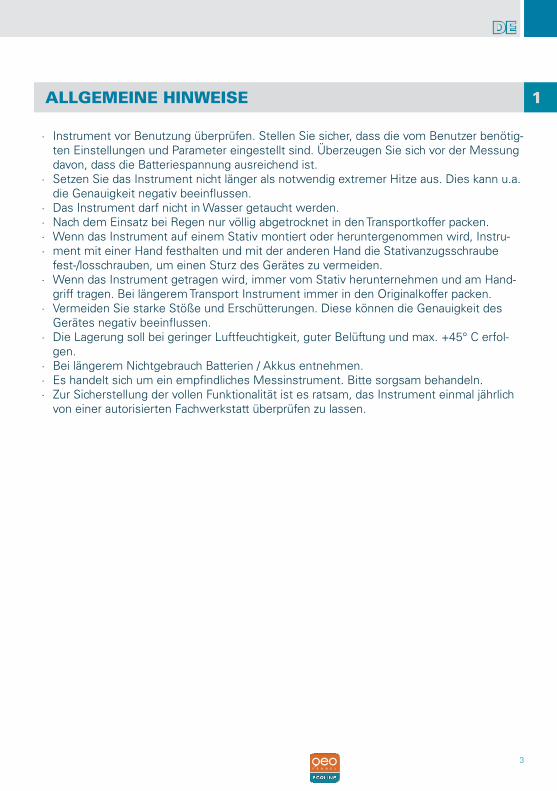
∙ Instrument vor Benutzung überprüfen. Stellen Sie sicher, dass die vom Benutzer benötig-ten Einstellungen und Parameter eingestellt sind. Überzeugen Sie sich vor der Messung davon, dass die Batteriespannung ausreichend ist.
∙ Setzen Sie das Instrument nicht länger als notwendig extremer Hitze aus. Dies kann u.a. die Genauigkeit negativ beeinflussen.
∙ Das Instrument darf nicht in Wasser getaucht werden. ∙ Nach dem Einsatz bei Regen nur völlig abgetrocknet in den Transportkoffer packen. ∙ Wenn das Instrument auf einem Stativ montiert oder heruntergenommen wird, Instru- ∙ ment mit einer Hand festhalten und mit der anderen Hand die Stativanzugsschraube
fest-/losschrauben, um einen Sturz des Gerätes zu vermeiden. ∙ Wenn das Instrument getragen wird, immer vom Stativ herunternehmen und am Hand-
griff tragen. Bei längerem Transport Instrument immer in den Originalkoffer packen. ∙ Vermeiden Sie starke Stöße und Erschütterungen. Diese können die Genauigkeit des
Gerätes negativ beeinflussen. ∙ Die Lagerung soll bei geringer Luftfeuchtigkeit, guter Belüftung und max. +45° C erfol-
gen. ∙ Bei längerem Nichtgebrauch Batterien / Akkus entnehmen. ∙ Es handelt sich um ein empfindliches Messinstrument. Bitte sorgsam behandeln. ∙ Zur Sicherstellung der vollen Funktionalität ist es ratsam, das Instrument einmal jährlich
von einer autorisierten Fachwerkstatt überprüfen zu lassen.
1

4
DE
5
DE
BEDIENELEMENTE
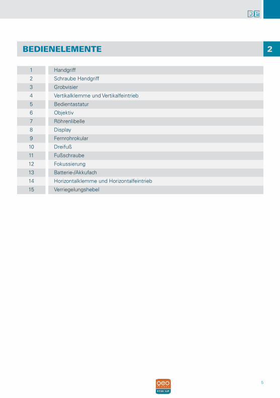
1 Handgriff
2 Schraube Handgriff
3 Grobvisier
4 Vertikalklemme und Vertikalfeintrieb
5 Bedientastatur
6 Objektiv
7 Röhrenlibelle
8 Display
9 Fernrohrokular
10 Dreifuß
11 Fußschraube
12 Fokussierung
13 Batterie-/Akkufach
14 Horizontalklemme und Horizontalfeintrieb
15 Verriegelungshebel
2
6
DE
ANZEIGE IM DISPLAY
BEDIENFELD
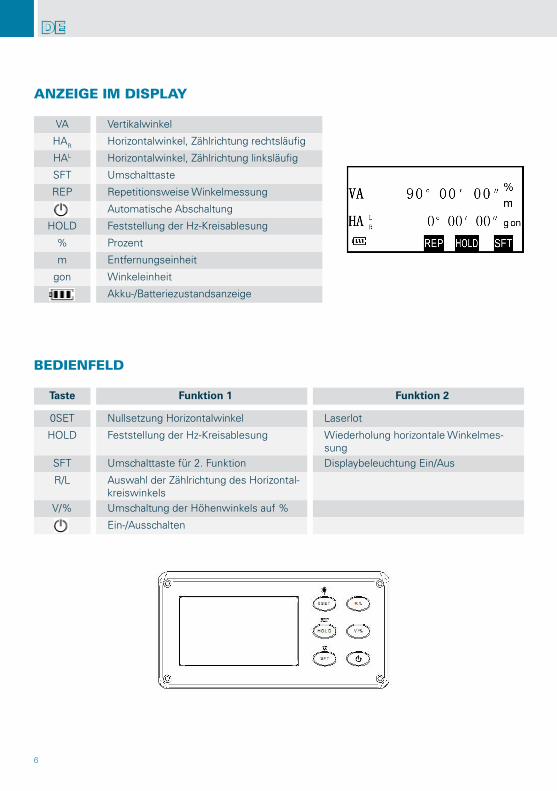
VA Vertikalwinkel
HAR Horizontalwinkel, Zählrichtung rechtsläufig
HAL Horizontalwinkel, Zählrichtung linksläufig
SFT Umschalttaste
REP Repetitionsweise Winkelmessung
Automatische Abschaltung
HOLD Feststellung der Hz-Kreisablesung
% Prozent
m Entfernungseinheit
gon Winkeleinheit
Akku-/Batteriezustandsanzeige
Taste Funktion 1 Funktion 2
0SET Nullsetzung Horizontalwinkel Laserlot
HOLD Feststellung der Hz-Kreisablesung Wiederholung horizontale Winkelmes-sung
SFT Umschalttaste für 2. Funktion Displaybeleuchtung Ein/Aus
R/L Auswahl der Zählrichtung des Horizontal-kreiswinkels
V/% Umschaltung der Höhenwinkels auf %
Ein-/Ausschalten
7
DE
VORBEREITUNG ZUR MESSUNG
BEDIENUNG
EINSCHALTEN
ZUSTANDSANZEIGE BATTERIE / AKKU
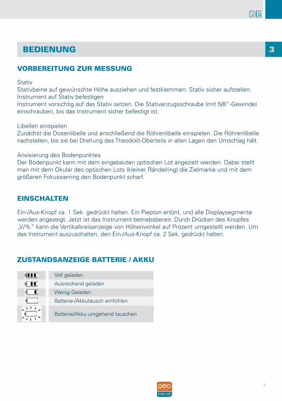
StativStativbeine auf gewünschte Höhe ausziehen und festklemmen. Stativ sicher aufstellen.Instrument auf Stativ befestigenInstrument vorsichtig auf das Stativ setzen. Die Stativanzugsschraube (mit 5/8“-Gewinde) einschrauben, bis das Instrument sicher befestigt ist.
Libellen einspielenZunächst die Dosenlibelle und anschließend die Röhrenlibelle einspielen. Die Röhrenlibelle nachstellen, bis sie bei Drehung des Theodolit-Oberteils in allen Lagen den Umschlag hält.
Anvisierung des BodenpunktesDer Bodenpunkt kann mit dem eingebauten optischen Lot angezielt werden. Dabei stellt man mit dem Okular des optischen Lots (kleiner Rändelring) die Zielmarke und mit dem größeren Fokussierring den Bodenpunkt scharf.
Ein-/Aus-Knopf ca. 1 Sek. gedrückt halten. Ein Piepton ertönt, und alle Displaysegmente werden angezeigt. Jetzt ist das Instrument betriebsbereit. Durch Drücken des Knopfes „V/%“ kann die Vertikalkreisanzeige von Höhenwinkel auf Prozent umgestellt werden. Um das Instrument auszuschalten, den Ein-/Aus-Knopf ca. 2 Sek. gedrückt halten.
Voll geladen
Ausreichend geladen
Wenig Geladen
Batterie-/Akkutausch emfohlen
Batterie/Akku umgehend tauschen
3
8
DE
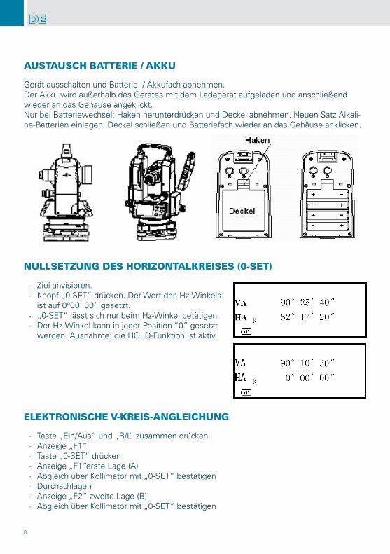
AUSTAUSCH BATTERIE / AKKU
NULLSETZUNG DES HORIZONTALKREISES (0-SET)
ELEKTRONISCHE V-KREIS-ANGLEICHUNG
Gerät ausschalten und Batterie- / Akkufach abnehmen.Der Akku wird außerhalb des Gerätes mit dem Ladegerät aufgeladen und anschließend wieder an das Gehäuse angeklickt.Nur bei Batteriewechsel: Haken herunterdrücken und Deckel abnehmen. Neuen Satz Alkali-ne-Batterien einlegen. Deckel schließen und Batteriefach wieder an das Gehäuse anklicken.
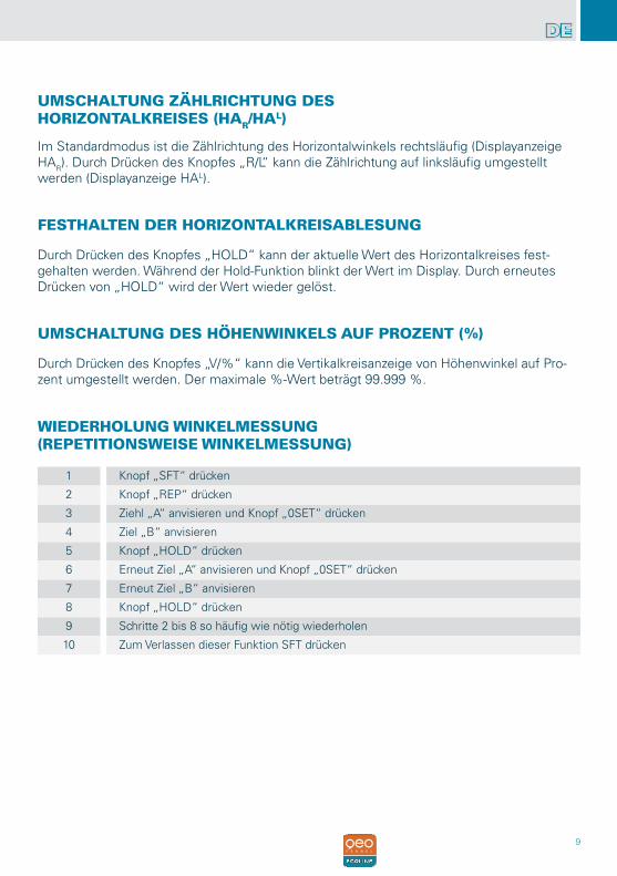
∙ Ziel anvisieren. ∙ Knopf „0-SET“ drücken. Der Wert des Hz-Winkels
ist auf 0°00’ 00” gesetzt. ∙ „0-SET“ lässt sich nur beim Hz-Winkel betätigen. ∙ Der Hz-Winkel kann in jeder Position “0” gesetzt
werden. Ausnahme: die HOLD-Funktion ist aktiv.
∙ Taste „Ein/Aus“ und „R/L“ zusammen drücken ∙ Anzeige „F1“ ∙ Taste „0-SET“ drücken ∙ Anzeige „F1“erste Lage (A) ∙ Abgleich über Kollimator mit „0-SET“ bestätigen ∙ Durchschlagen ∙ Anzeige „F2“ zweite Lage (B) ∙ Abgleich über Kollimator mit „0-SET“ bestätigen
9
DE
UMSCHALTUNG ZÄHLRICHTUNG DESHORIZONTALKREISES (HAR/HAL)
FESTHALTEN DER HORIZONTALKREISABLESUNG
UMSCHALTUNG DES HÖHENWINKELS AUF PROZENT (%)
WIEDERHOLUNG WINKELMESSUNG(REPETITIONSWEISE WINKELMESSUNG)
Im Standardmodus ist die Zählrichtung des Horizontalwinkels rechtsläufig (Displayanzeige HAR). Durch Drücken des Knopfes „R/L“ kann die Zählrichtung auf linksläufig umgestellt werden (Displayanzeige HAL).
Durch Drücken des Knopfes „HOLD“ kann der aktuelle Wert des Horizontalkreises fest-gehalten werden. Während der Hold-Funktion blinkt der Wert im Display. Durch erneutes Drücken von „HOLD“ wird der Wert wieder gelöst.
Durch Drücken des Knopfes „V/%“ kann die Vertikalkreisanzeige von Höhenwinkel auf Pro-zent umgestellt werden. Der maximale %-Wert beträgt 99.999 %.
1 Knopf „SFT“ drücken
2 Knopf „REP“ drücken
3 Ziehl „A“ anvisieren und Knopf „0SET“ drücken
4 Ziel „B“ anvisieren
5 Knopf „HOLD“ drücken
6 Erneut Ziel „A“ anvisieren und Knopf „0SET“ drücken
7 Erneut Ziel „B“ anvisieren
8 Knopf „HOLD“ drücken
9 Schritte 2 bis 8 so häufig wie nötig wiederholen
10 Zum Verlassen dieser Funktion SFT drücken
10
DE
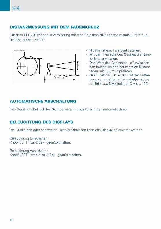
Mit dem ELT 220 können in Verbindung mit einer Teleskop-Nivellierlatte manuell Entfernun-gen gemessen werden.
Das Gerät schaltet sich bei Nichtbenutzung nach 20 Minuten automatisch ab.
Bei Dunkelheit oder schlechten Lichtverhältnissen kann das Display beleuchtet werden.
Beleuchtung Einschalten:Knopf „SFT“ ca. 2 Sek. gedrückt halten.
Beleuchtung Ausschalten:Knopf „SFT“ erneut ca. 2 Sek. gedrückt halten.
DISTANZMESSUNG MIT DEM FADENKREUZ
AUTOMATISCHE ABSCHALTUNG
BELEUCHTUNG DES DISPLAYS
∙ Nivellierlatte auf Zielpunkt stellen. ∙ Mit dem Fernrohr des Gerätes die Nivel-
lierlatte anvisieren. ∙ Den Wert des Abschnitts „d“ zwischen
den beiden kleinen horizontalen Distanz-fäden mit 100 multiplizieren.
∙ Das Ergebnis „D“ entspricht der Entfer-nung vom Instrumentenmittelpunkt bis zur Teleskop-Nivellierlatte (D = d x 100).
11
DE
∙ Knopf „Ein/Aus“ und „0Set“ gleichzeitig drücken. ∙ Um die gewünschten Ziffern (1-4) anzuwählen, Taste „0SET“ oder „HOLD“ drücken. ∙ Um den Parameter umzustellen die Taste „R/L“ oder „V/%“ drücken. ∙ Um das Menü zu verlassen „SFT“ drücken. ∙ Die geänderten Parameter bleiben auch nach Aus-/Einschalten des Gerätes gespeichert.
EINSTELLUNG VON GERÄTEPARAMETERN
PARAMETER SETZEN
Ziffer Parameter Setzen
1 Vertikale Winkelanzeige Umschaltung zwischen Zenith und horizontal
Setting ONhorizontal
Setting OFFzenith
2 Automatische Abschaltung Abschaltung Ein-/Ausschal-ten
Setting ONEin
Setting OFFAus
3 Minimale Winkeleinheit Umschaltung zwischen 10“ und 20“
Setting ON10“
Setting OFF20“
4 Winkeleinheit Umschaltung zwischen DEG (Grad) und GON
Setting ONGON
Setting OFFDEG (Grad)
12
DE
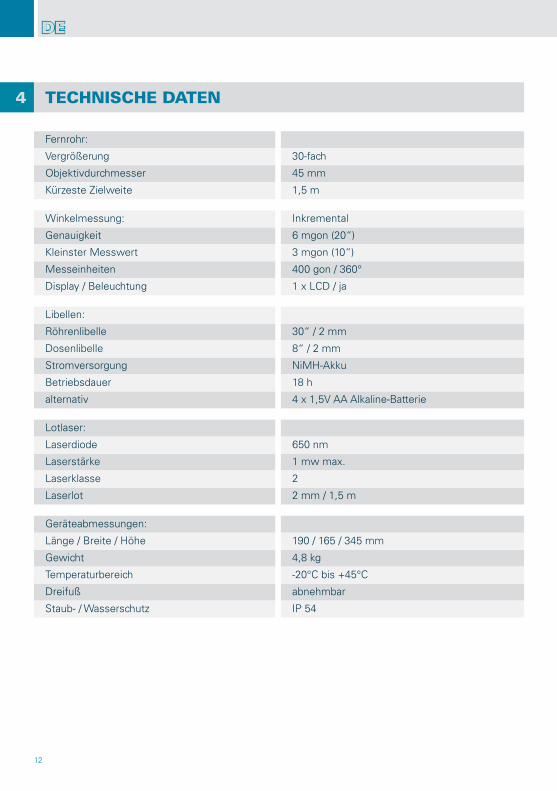
TECHNISCHE DATEN
Fernrohr:
Vergrößerung 30-fach
Objektivdurchmesser 45 mm
Kürzeste Zielweite 1,5 m
Winkelmessung: Inkremental
Genauigkeit 6 mgon (20“)
Kleinster Messwert 3 mgon (10“)
Messeinheiten 400 gon / 360°
Display / Beleuchtung 1 x LCD / ja
Libellen:
Röhrenlibelle 30“ / 2 mm
Dosenlibelle 8“ / 2 mm
Stromversorgung NiMH-Akku
Betriebsdauer 18 h
alternativ 4 x 1,5V AA Alkaline-Batterie
Lotlaser:
Laserdiode 650 nm
Laserstärke 1 mw max.
Laserklasse 2
Laserlot 2 mm / 1,5 m
Geräteabmessungen:
Länge / Breite / Höhe 190 / 165 / 345 mm
Gewicht 4,8 kg
Temperaturbereich -20°C bis +45°C
Dreifuß abnehmbar
Staub- / Wasserschutz IP 54
4
13
DE
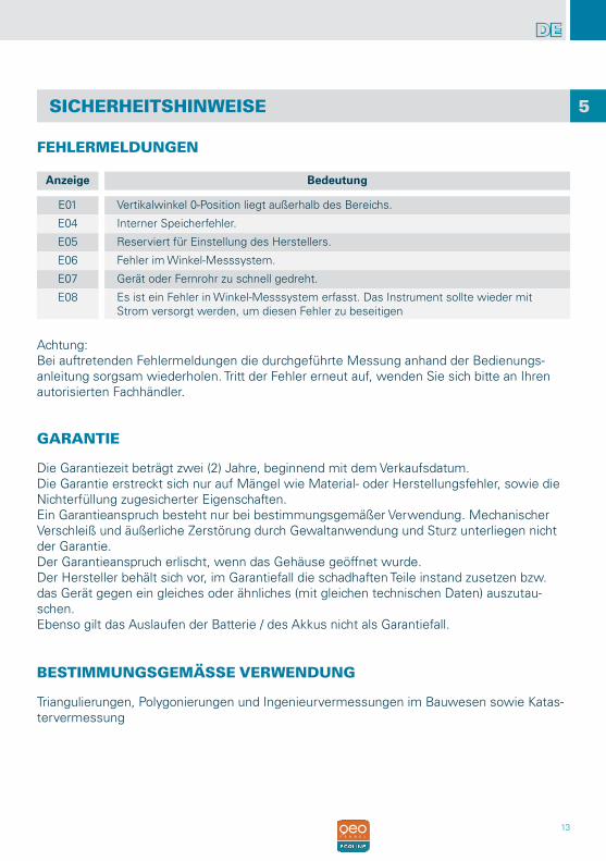
SICHERHEITSHINWEISE
FEHLERMELDUNGEN
Anzeige Bedeutung
E01 Vertikalwinkel 0-Position liegt außerhalb des Bereichs.
E04 Interner Speicherfehler.
E05 Reserviert für Einstellung des Herstellers.
E06 Fehler im Winkel-Messsystem.
E07 Gerät oder Fernrohr zu schnell gedreht.
E08 Es ist ein Fehler in Winkel-Messsystem erfasst. Das Instrument sollte wieder mit Strom versorgt werden, um diesen Fehler zu beseitigen
GARANTIE
Die Garantiezeit beträgt zwei (2) Jahre, beginnend mit dem Verkaufsdatum.Die Garantie erstreckt sich nur auf Mängel wie Material- oder Herstellungsfehler, sowie die Nichterfüllung zugesicherter Eigenschaften.Ein Garantieanspruch besteht nur bei bestimmungsgemäßer Verwendung. Mechanischer Verschleiß und äußerliche Zerstörung durch Gewaltanwendung und Sturz unterliegen nicht der Garantie.Der Garantieanspruch erlischt, wenn das Gehäuse geöffnet wurde.Der Hersteller behält sich vor, im Garantiefall die schadhaften Teile instand zusetzen bzw. das Gerät gegen ein gleiches oder ähnliches (mit gleichen technischen Daten) auszutau-schen.Ebenso gilt das Auslaufen der Batterie / des Akkus nicht als Garantiefall.
5
BESTIMMUNGSGEMÄSSE VERWENDUNG
Triangulierungen, Polygonierungen und Ingenieurvermessungen im Bauwesen sowie Katas-tervermessung
Achtung:Bei auftretenden Fehlermeldungen die durchgeführte Messung anhand der Bedienungs-anleitung sorgsam wiederholen. Tritt der Fehler erneut auf, wenden Sie sich bitte an Ihren autorisierten Fachhändler.
14
DE
UMGANG UND PFLEGE
CE-KONFORMITÄT
WARN- UND SICHERHEITSHINWEISE
UMSTÄNDE, DIE DAS MESSERGEBNIS VERFÄLSCHEN KÖNNENV
ELEKTROMAGNETISCHE VERTRÄGLICHKEIT
Messinstrumente generell sorgsam behandeln. Nach Benutzung mit weichem Tuch reinigen (ggfs. Tuch in etwas Wasser tränken). Wenn das Gerät feucht war, sorgsam trocknen. Erst in den Koffer oder die Tasche packen, wenn es absolut trocken ist. Transport nur in Originalbe-hälter oder -tasche.
Es kann nicht generell ausgeschlossen werden, dass das Gerät andere Geräte stört (z.B. Navigationseinrichtungen) oder durch andere Geräte gestört wird (z.B. elektromagnetische Strahlung bei erhöhter Feldstärke z.B. in der unmittelbaren Nähe von Industrieanlagen oder Rundfunksendern).
Das Gerät hat das CE-Zeichen gemäß den Normen EN 55011:2007 EN 61000-6-1:2007.
∙ Bitte richten Sie sich nach den Anweisungen der Bedienungsanleitung. ∙ Anleitung vor Benutzung des Gerätes lesen. ∙ Instrument nur für Vermessungen benutzen. ∙ Niemals das Gehäuse öffnen. Reparaturen nur vom autorisierten Fachhändler durchfüh-
ren lassen. ∙ Keine Warn- oder Sicherheitshinweise entfernen. ∙ Instrument nicht in Kinderhände gelangen lassen. ∙ Gerät nicht in explosionsgefährdeter Umgebung betreiben.
Messungen durch Glas- oder Plastikscheiben;Sturz oder starker Stoß. Bitte Genauigkeit überprüfen.Große Temperaturveränderungen: Wenn das Gerät aus warmer Umgebung in eine kalte oder umgekehrt gebracht wird, vor Benutzung einige Minuten warten.
15
DE
HAFTUNGSAUSSCHLUSS
∙ Der Benutzer dieses Produktes ist angehalten, sich exakt an die Anweisungen der Bedie-nungsanleitung zu halten. Alle Geräte sind vor der Auslieferung genauestens überprüft worden. Der Anwender sollte sich trotzdem vor jeder Anwendung von der Genauigkeit des Gerätes überzeugen.
∙ Der Hersteller und sein Vertreter haften nicht für fehlerhafte oder absichtlich falsche Ver-wendung sowie daraus eventuell resultierende Folgeschäden und entgangenen Gewinn.
∙ Der Hersteller und sein Vertreter haften nicht für Folgeschäden und entgangenen Ge-winn durch Naturkatastrophen wie z.B. Erdbeben, Sturm, Flut, usw. sowie Feuer, Unfall, Eingriffe durch Dritte oder einer Verwendung außerhalb der üblichen Einsatzbereiche.
∙ Der Hersteller und sein Vertreter haften nicht für Schäden und entgangenen Gewinn durch geänderte oder verlorene Daten, Unterbrechung des Geschäftsbetriebes usw., die durch das Produkt oder die nicht mögliche Verwendung des Produktes verursacht wurden.
∙ Der Hersteller und sein Vertreter haften nicht für Schäden und entgangenen Gewinn resultierend aus einer nicht anleitungsgemäßen Bedienung.
∙ Der Hersteller und sein Vertreter haften nicht für Schäden, die durch unsachgemäße Verwendung oder in Verbindung mit Produkten anderer Hersteller verursacht wurden.
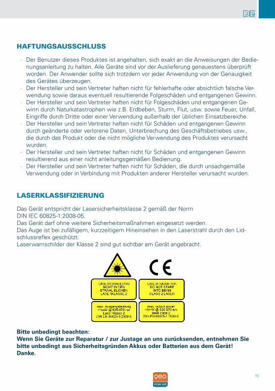
LASERKLASSIFIZIERUNG
Das Gerät entspricht der Lasersicherheitsklasse 2 gemäß der NormDIN IEC 60825-1:2008-05.Das Gerät darf ohne weitere Sicherheitsmaßnahmen eingesetzt werden.Das Auge ist bei zufälligem, kurzzeitigem Hineinsehen in den Laserstrahl durch den Lid-schlussreflex geschützt.Laserwarnschilder der Klasse 2 sind gut sichtbar am Gerät angebracht.
Bitte unbedingt beachten:Wenn Sie Geräte zur Reparatur / zur Justage an uns zurücksenden, entnehmen Sie bitte unbedingt aus Sicherheitsgründen Akkus oder Batterien aus dem Gerät!Danke.
16
EN
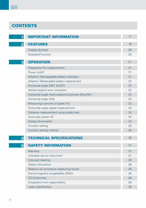
1 IMPORTANT INFORMATION 17
2 FEATURES 19
Display Symbols 20
Keyboard Function 20
3 OPERATION 21
Preparation for measurement 21
Power on/off 21
Alkaline / Rechargeable battery indication 21
Alkaline / Rechargable battery replacement 22
Horizontal angle 0SET (0-SET) 22
Vertical angle 0 error correction 22
Horizontal angle clockwise/anti-clockwise (HAR/HAL) 23
Horizontal angle Hold 23
Measuring a percent of grade (%) 23
Horizontal angle repeat measurement 23
Distance measurement using stadia lines 24
Automatic power off 24
Display Illumination 24
Function setting 25
Function setting method 25
4 TECHNICAL SPECIFICATIONS 26
5 SAFETY INFORMATION 27
Warranty 27
Intended use on instrument 27
Care and cleaning 28
Safety instructions 28
Reasons for erroneous measuring results 28
Electromagnetic acceptability (EMC) 28
CE-Conformity 28
Exceptions from responsibility 29
Laser classification 29
CONTENTS
17
EN
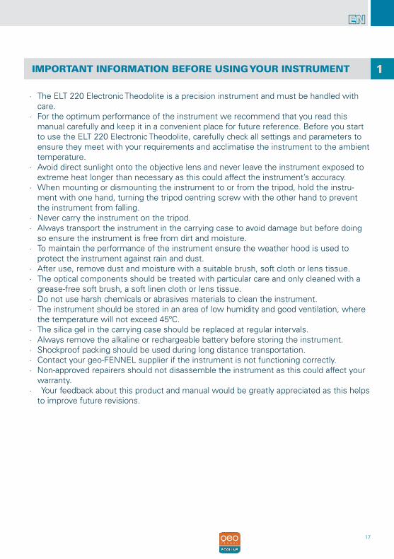
IMPORTANT INFORMATION BEFORE USING YOUR INSTRUMENT
∙ The ELT 220 Electronic Theodolite is a precision instrument and must be handled with care.
∙ For the optimum performance of the instrument we recommend that you read this manual carefully and keep it in a convenient place for future reference. Before you start to use the ELT 220 Electronic Theodolite, carefully check all settings and parameters to ensure they meet with your requirements and acclimatise the instrument to the ambient temperature.
∙ Avoid direct sunlight onto the objective lens and never leave the instrument exposed to extreme heat longer than necessary as this could affect the instrument’s accuracy.
∙ When mounting or dismounting the instrument to or from the tripod, hold the instru-ment with one hand, turning the tripod centring screw with the other hand to prevent the instrument from falling.
∙ Never carry the instrument on the tripod. ∙ Always transport the instrument in the carrying case to avoid damage but before doing
so ensure the instrument is free from dirt and moisture. ∙ To maintain the performance of the instrument ensure the weather hood is used to
protect the instrument against rain and dust. ∙ After use, remove dust and moisture with a suitable brush, soft cloth or lens tissue. ∙ The optical components should be treated with particular care and only cleaned with a
grease-free soft brush, a soft linen cloth or lens tissue. ∙ Do not use harsh chemicals or abrasives materials to clean the instrument. ∙ The instrument should be stored in an area of low humidity and good ventilation, where
the temperature will not exceed 45ºC. ∙ The silica gel in the carrying case should be replaced at regular intervals. ∙ Always remove the alkaline or rechargeable battery before storing the instrument. ∙ Shockproof packing should be used during long distance transportation. ∙ Contact your geo-FENNEL supplier if the instrument is not functioning correctly. ∙ Non-approved repairers should not disassemble the instrument as this could affect your
warranty. ∙ Your feedback about this product and manual would be greatly appreciated as this helps
to improve future revisions.
1
18
EN
19
EN
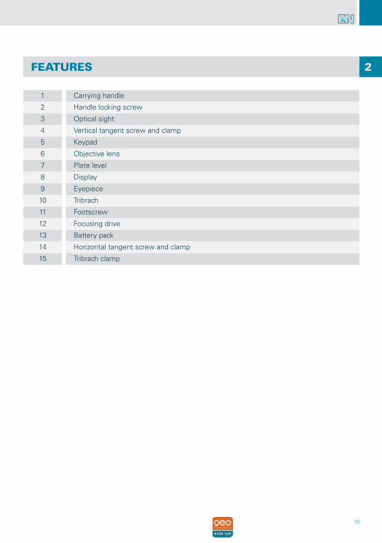
FEATURES 2
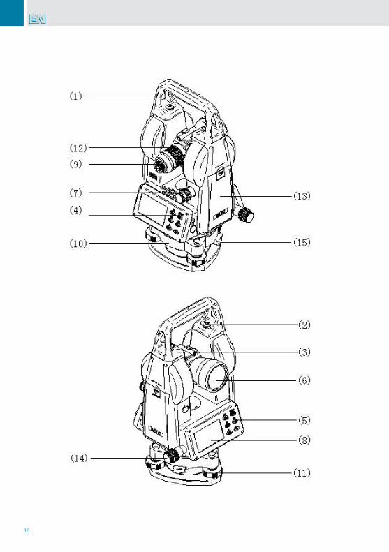
1 Carrying handle
2 Handle locking screw
3 Optical sight
4 Vertical tangent screw and clamp
5 Keypad
6 Objective lens
7 Plate level
8 Display
9 Eyepiece
10 Tribrach
11 Footscrew
12 Focusing drive
13 Battery pack
14 Horizontal tangent screw and clamp
15 Tribrach clamp
20
EN
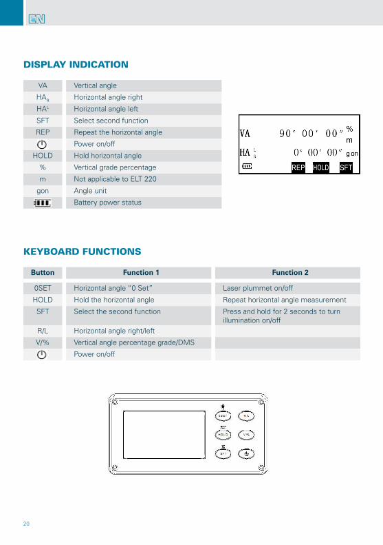
DISPLAY INDICATION
KEYBOARD FUNCTIONS
VA Vertical angle
HAR Horizontal angle right
HAL Horizontal angle left
SFT Select second function
REP Repeat the horizontal angle
Power on/off
HOLD Hold horizontal angle
% Vertical grade percentage
m Not applicable to ELT 220
gon Angle unit
Battery power status
Button Function 1 Function 2
0SET Horizontal angle “0 Set” Laser plummet on/off
HOLD Hold the horizontal angle Repeat horizontal angle measurement
SFT Select the second function Press and hold for 2 seconds to turn illumination on/off
R/L Horizontal angle right/left
V/% Vertical angle percentage grade/DMS
Power on/off
21
EN
PREPARATION FOR MEASUREMENT
OPERATION
POWER ON
ALKALINE / RECHARGEABLE BATTERY INDICATION
Level and centrer the instrument precisely to ensure optimum performance.
Setting up the instrument and tripodExtend the tripod legs to a suitable height and tighten the locking screw.Attach the instrument onto the tripod carefully. With the tripod centring screw slightly loose move the instrument across the tripod head until the laser plum-met is in coincidence with the ground point.Level the instrument with the circular bubble vialUse footscrews 1& 2 to move the air bubble in the circular vial so it is centred left to right. Use footscrew 3 to move the air bubble to the centre of the vial.
Accurately level the instrument with the plate levelRelease the horizontal clamp and rotate the instrument until the plate level is parallel with the footscrew 1& 2. Centre the plate level bubble using the same two footscrews. Turn the instrument 90°and centre the bubble using footscrew 3.Repeat this procedure until the bubble in the plate level is centred in all positions.
Please observe the relationship between the direction of rotation of the footscrews and the moving direction of the bubble.
When pressing the power button for 1 sec. an audio tone sounds followed by a test period of about 2 seconds when all segments are displayed on the LCD to confirm the instrument is ready for usePress the power button and hold for 2 seconds to power off the instrument.
Full power
Effective
Low power but still effective
Very low power, replace the alkaline battery / recharge NiMH battery pack
Instrument will shortly power/off automatically.Replace alkaline battery / recharge NiMH battery pack immediately
3
22
EN
CHANGE THE BATTERIES
HORIZONTAL ANGLE OSET (0SET)
VERTICAL ANGLE 0 ERROR CORRECTION
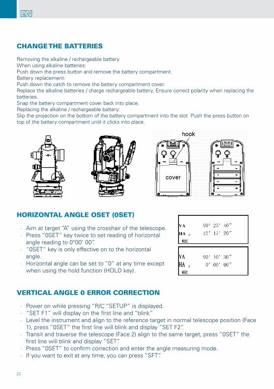
Removing the alkaline / rechargeable batteryWhen using alkaline batteries:Push down the press button and remove the battery compartment.Battery replacement:Push down the catch to remove the battery compartment cover.Replace the alkaline batteries / charge rechargeable battery. Ensure correct polarity when replacing the batteries.Snap the battery compartment cover back into place.Replacing the alkaline / rechargeable battery:Slip the projection on the bottom of the battery compartment into the slot. Push the press button on top of the battery compartment until it clicks into place.
∙ Aim at target “A” using the crosshair of the telescope. ∙ Press “0SET“ key twice to set reading of horizontal
angle reading to 0°00’ 00”. ∙ “0SET“ key is only effective on to the horizontal
angle. ∙ Horizontal angle can be set to “0“ at any time except
when using the hold function (HOLD key).
∙ Power on while pressing “R/L“, “SETUP” is displayed. ∙ “SET F1” will display on the first line and “blink” ∙ Level the instrument and align to the reference target in normal telescope position (Face
1), press “0SET“ the first line will blink and display “SET F2”. ∙ Transit and traverse the telescope (Face 2) align to the same target, press “0SET“ the
first line will blink and display “SET”. ∙ Press “0SET“ to confirm correction and enter the angle measuring mode. ∙ If you want to exit at any time, you can press “SFT“.
23
EN
HORIZONTAL ANGLE CLOCKWISE/ANTI-CLOCKWISE (HAR/HAL)
HORIZONTAL ANGLE “HOLD”
MEASURING A PERCENT OF GRADE (SLOPE MEASUREMENT %)
ANGULAR REPEATED MEASUREMENT
Aim at target “A” using the crosshair of the telescope.Press “R/L“ key, to change transform horizontal angle mode HAR into the mode HAL. Measuring by mode HAL. “R/L“ key has no effect on the vertical angle.Press “R/L“ key once again to change mode HAL into mode HAR
Turn the tangent screw until you have the required horizontal angle.Press “HOLD“ key once, and the value of the horizontal angle “blinks”.Press “HOLD“ key once again to hold the horizontal angle.Aim at the target.Press “HOLD“ key, once again to release at the required horizontal angle.The “HOLD“ key has no effect on the vertical angle.
Press “V%“ the display of vertical angle switches to percent of grade. Press “V%“ again.The display reverts back to normal angle measurement mode.
1 Press “SFT“ key
2 Press “REP“ key
3 Aim at a target “A” and press “0SET“ key
4 Aim the target “B“
5 Press “HOLD“ key
6 Aim the target “A” once again and press “0SET“ key
7 Aim the target “B” once again
8 Press “HOLD“ key
9 Repeat 2-8 to measure the desired number of repetitions
10 Press “SFT“ to exit from this mode
24
EN
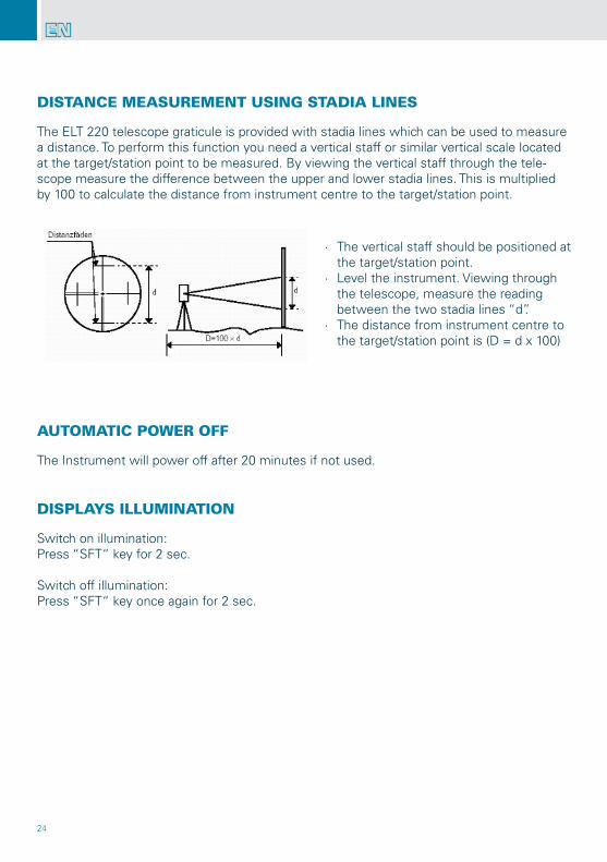
The ELT 220 telescope graticule is provided with stadia lines which can be used to measure a distance. To perform this function you need a vertical staff or similar vertical scale located at the target/station point to be measured. By viewing the vertical staff through the tele-scope measure the difference between the upper and lower stadia lines. This is multiplied by 100 to calculate the distance from instrument centre to the target/station point.
The Instrument will power off after 20 minutes if not used.
Switch on illumination:Press “SFT“ key for 2 sec.
Switch off illumination:Press “SFT“ key once again for 2 sec.
DISTANCE MEASUREMENT USING STADIA LINES
AUTOMATIC POWER OFF
DISPLAYS ILLUMINATION
∙ The vertical staff should be positioned at the target/station point.
∙ Level the instrument. Viewing through the telescope, measure the reading between the two stadia lines “d”.
∙ The distance from instrument centre to the target/station point is (D = d x 100)
25
EN
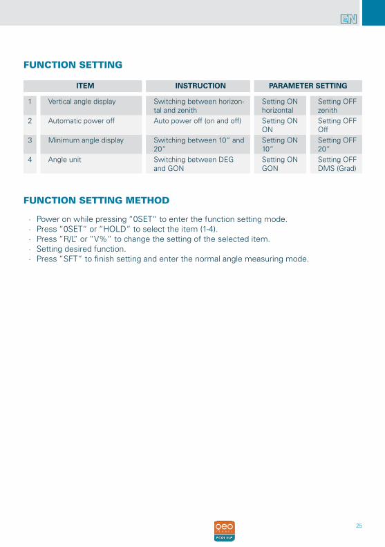
∙ Power on while pressing “0SET“ to enter the function setting mode. ∙ Press “0SET“ or “HOLD“ to select the item (1-4). ∙ Press “R/L“ or “V%“ to change the setting of the selected item. ∙ Setting desired function. ∙ Press “SFT“ to finish setting and enter the normal angle measuring mode.
FUNCTION SETTING
FUNCTION SETTING METHOD
ITEM INSTRUCTION PARAMETER SETTING
1 Vertical angle display Switching between horizon-tal and zenith
Setting ONhorizontal
Setting OFFzenith
2 Automatic power off Auto power off (on and off) Setting ONON
Setting OFFOff
3 Minimum angle display Switching between 10“ and 20“
Setting ON10“
Setting OFF20“
4 Angle unit Switching between DEG and GON
Setting ONGON
Setting OFFDMS (Grad)
26
EN
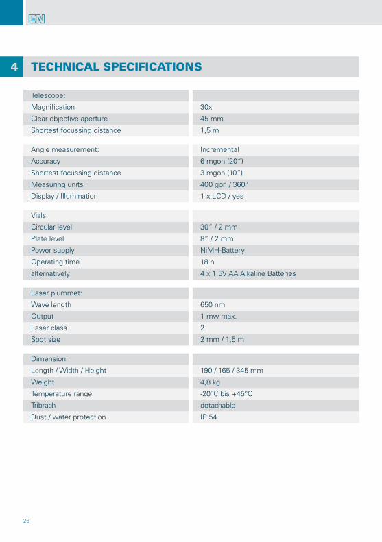
TECHNICAL SPECIFICATIONS
Telescope:
Magnification 30x
Clear objective aperture 45 mm
Shortest focussing distance 1,5 m
Angle measurement: Incremental
Accuracy 6 mgon (20“)
Shortest focussing distance 3 mgon (10“)
Measuring units 400 gon / 360°
Display / Illumination 1 x LCD / yes
Vials:
Circular level 30“ / 2 mm
Plate level 8“ / 2 mm
Power supply NiMH-Battery
Operating time 18 h
alternatively 4 x 1,5V AA Alkaline Batteries
Laser plummet:
Wave length 650 nm
Output 1 mw max.
Laser class 2
Spot size 2 mm / 1,5 m
Dimension:
Length / Width / Height 190 / 165 / 345 mm
Weight 4,8 kg
Temperature range -20°C bis +45°C
Tribrach detachable
Dust / water protection IP 54
4
27
EN
SAFETY INFORMATION
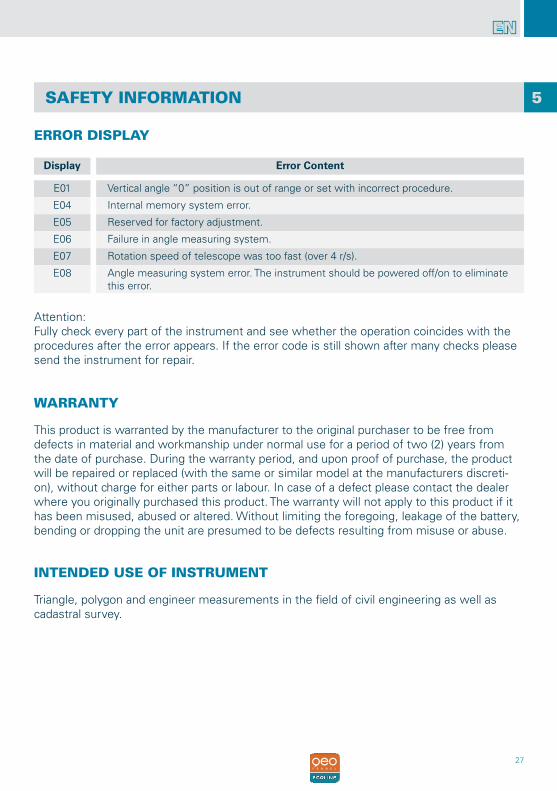
ERROR DISPLAY
Display Error Content
E01 Vertical angle “0” position is out of range or set with incorrect procedure.
E04 Internal memory system error.
E05 Reserved for factory adjustment.
E06 Failure in angle measuring system.
E07 Rotation speed of telescope was too fast (over 4 r/s).
E08 Angle measuring system error. The instrument should be powered off/on to eliminate this error.
WARRANTY
This product is warranted by the manufacturer to the original purchaser to be free from defects in material and workmanship under normal use for a period of two (2) years from the date of purchase. During the warranty period, and upon proof of purchase, the product will be repaired or replaced (with the same or similar model at the manufacturers discreti-on), without charge for either parts or labour. In case of a defect please contact the dealer where you originally purchased this product. The warranty will not apply to this product if it has been misused, abused or altered. Without limiting the foregoing, leakage of the battery, bending or dropping the unit are presumed to be defects resulting from misuse or abuse.
5
INTENDED USE OF INSTRUMENT
Triangle, polygon and engineer measurements in the field of civil engineering as well as cadastral survey.
Attention:Fully check every part of the instrument and see whether the operation coincides with the procedures after the error appears. If the error code is still shown after many checks please send the instrument for repair.
28
EN
CARE AND CLEANING
CE-CONFORMITY
SAFETY INSTRUCTIONS
SPECIFIC REASONS FOR ERRONEOUS MEASURING RESULTS
ELECTROMAGNETIC ACCEPTABILITY (EMC)
Please handle measuring instruments with care.After use, remove dust and moisture with a suitable brush, soft cloth or lens tissue.The optical components should be treated with particular care and only cleaned with a grease-free soft brush, a soft linen cloth or lens tissue.Always transport the instrument in the carrying case to avoid damage but before doing so ensure the instrument is free from dirt and moisture.Only transport the instrument in its original carrying case/container.
It cannot be completely excluded that this instrument will disturb other instruments (e.g. navigation systems); will be disturbed by other instruments (e.g. intensive electromagnetic radiation nearby industrial facilities or radio transmitters).
Instrument has CE-mark according to EN 55011:2007, EN 61000-6-1:2007.
∙ Please follow the instructions detailed in User Manual. ∙ Only use the instrument for its intended applications. ∙ Do not open instrument housing. Repairs should be carried out by authorized workshops
only. Please contact your local geo-FENNEL dealer. ∙ Do not remove warning labels or safety instructions. ∙ Keep instrument away from children. ∙ Do not use instrument in explosive environment.
Measurements through glass or plastic windows.Dirty optical components or laser emitting window.After instrument has been dropped or hit. Please check accuracy.Large fluctuation of temperature: acclimatise the instrument to the ambient temperature.
29
EN
EXCEPTIONS FROM RESPONSIBILITY
∙ The user of this product is expected to follow the instructions given in the User Manu-al. Although all instruments leave our warehouse in perfect condition and adjustment the user is expected to carry out periodic checks of the product’s accuracy and general performance.
∙ The manufacturer, or its representatives, assumes no responsibility of results of a faulty or intentional usage or misuse including any direct, indirect, consequential damage, and loss of profits.
∙ The manufacturer, or its representatives, assumes no responsibility for consequential damage, and loss of profits by any disaster (earthquake, storm, flood etc.), fire, accident, or an act of a third party and/or a usage in other than usual conditions.
∙ The manufacturer, or its representatives, assumes no responsibility for any damage, and loss of profits due to a change of data, loss of data and interruption of business etc., caused by using the product or an unusable product.
∙ The manufacturer, or its representatives, assumes no responsibility for any damage, and loss of profits caused by usage other than explained in the User Manual.
∙ The manufacturer, or its representatives, assumes no responsibility for damage caused by wrong movement or action due to connecting with other products.
LASER CLASSIFICATION
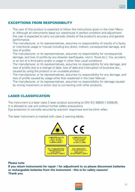
The instrument is a laser class 2 laser product according to DIN IEC 60825-1:2008-05.It is allowed to use unit without further safety precautions.Eye protection is normally secured by aversion responses and the blink reflex.
The laser instrument is marked with class 2 warning labels.
Please note:If you return instruments for repair / for adjustment to us please disconnect batteries or rechargeable batteries from the instrument - this is for safety reasons! Thank you.
30
FR
1 IMPORTANT 31
2 CARACTÉRISTIQUES 33
Indication de l‘écran 34
Panneau de commande 34
3 OPÉRATION 35
Préparation pour la mesure 35
Marche 35
Témoin piles Alcalines / batterie rechargeable 35
Remplacement piles alcalines / batterie rechargeable 36
Paramètrage angle 0 horizontal (0SET) 36
Correction d‘erreur sur l‘angle vertical 0 36
Mode conversion de l‘horizontal vers la droite et vers la gauche en tournant l‘incrément (HAR/HAL)
37
Blocage et déblocage de l‘angle horizontal 37
Mesure du pourcentage de pente (%) 37
Mesure angulaire répétée 37
Mesure de la distance 38
Arrêt automatique 38
Eclairage de l‘écran 38
Paramètrage des fonctions 39
Procédé de paramètrage des fonctions 39
4 SPÉCIFICATIONS TECHNIQUES 40
5 CONSIGNES DE SÉCURITÉ 41
Garantie 41
Utilisation appropriée de l‘instrument 41
Entretien et nettoyage 42
Consignes de sécurité 42
Rraisons spécifiques pour résultats de mesure erronés 42
Compatibilité électromagnétique (EMC) 42
Conformité CE 42
Exclusion de responsabilité 43
Classification du laser 43
TABLE DES MATIERES
31
FR
IMPORTANT LIRE AVANT D‘UTILISER VOTRE INSTRUMENT
∙ Faire un contrôle complet de l‘appareil avant de l‘utiliser. Assurez-vous que les fonctions de l‘instrument, alimentation, les réglages d‘origine et des paramètres répondent à vos besoins avant de l‘utiliser.
∙ Pour éviter les rayons directs du soleil sur la lentille de l‘appareil, ne jamais laisser l‘appareil se trouvant sous une chaleur importante plus longtemps que nécessaire, ou cela pourrait affecter la précision de l‘ instrument.
∙ Lors du montage ou du démontage de l‘instrument sur le trépied, tenir l‘instrument avec une main, faire tourner la vis centrale du trépied avec l‘autre main pour empêcher l‘appareil de tomber. Si l‘instrument doit être bougé tout en étant fixé sur le trépied, tenir l‘instrument le plus verticalement possible. Ne transportez jamais l‘appareil horizon-talement au-dessus de votre épaule. Tout transport sur une longue distance doit être effectué avec l‘instrument dans son étui.
∙ Mettez l‘instrument dans son étui pour éviter extrusion, accident et chocs pendant le transport. Coussin anti-choc doit être nécessairement mis à l‘intérieur de la mallette de transport pendant le transport sur une longue distance.
∙ Nettoyer la saleté sur la surface du verre et sur la coque à l‘aide d‘un chiffon ou d‘une brosse après l‘utilisation de l‘instrument. Sécher l‘instrument immédiatement après une utilisation sous la pluie.
∙ Ne pas utiliser de produits chimiques pour nettoyer la surface du verre et les compo-sants en plastique. Un simple chiffon imbibé d‘eau est nécessaire .
∙ Utilisez un coton absorbant ou un tissu spécial lunettes pour nettoyer les pièces op-tiques qui sont exposés. Mouchoir, des vêtements ou d‘autres choses de ce genre sont interdites pour le nettoyage.
∙ L‘instrument doit être stocké dans une zone de faible humidité et bien aérés, où la tem-pérature ne doit pas dépasser 110 º F ( 45 º C). Il est nécessaire de remplacer le déshyd-ratant régulièrement dans la mallette.
∙ Toujours enlever la pile alcaline / batterie rechargeable avant de ranger l‘appareil. ∙ S‘il vous plaît contacter notre société si les fonctions de l‘ instrument paraissent anorma-
les. Les réparateurs non professionnels ne sont pas autorisés à démonter l‘appareil.
1

32
FR
33
FR
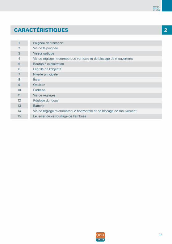
CARACTÉRISTIQUES
1 Poignée de transport
2 Vis de la poignée
3 Viseur optique
4 Vis de réglage micrométrique verticale et de blocage de mouvement
5 Bouton d‘exploitation
6 Lentille de l‘objectif
7 Nivelle principale
8 Écran
9 Oculaire
10 Embase
11 Vis de réglages
12 Réglage du focus
13 Batterie
14 Vis de réglage micrométrique horizontale et de blocage de mouvement
15 Le levier de verrouillage de l‘embase
2
34
FR
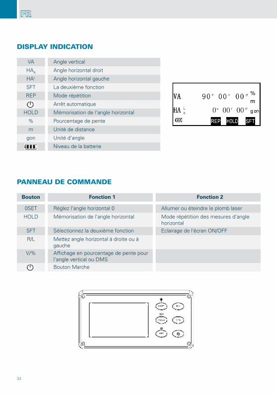
DISPLAY INDICATION
PANNEAU DE COMMANDE
VA Angle vertical
HAR Angle horizontal droit
HAL Angle horizontal gauche
SFT La deuxième fonction
REP Mode répétition
Arrêt automatique
HOLD Mémorisation de l‘angle horizontal
% Pourcentage de pente
m Unité de distance
gon Unité d‘angle
Niveau de la batterie
Bouton Fonction 1 Fonction 2
0SET Réglez l‘angle horizontal 0 Allumer ou éteindre le plomb laser
HOLD Mémorisation de l‘angle horizontal Mode répétition des mesures d‘angle horizontal
SFT Sélectionnez la deuxième fonction Eclairage de l‘écran ON/OFF
R/L Mettez angle horizontal à droite ou à gauche
V/% Affichage en pourcentage de pente pour l‘angle vertical ou DMSBouton Marche
35
FR
MISE EN STATION DU THÉODOLITE
OPÉRATION
MISE EN MARCHE
TÉMOIN DE PILES / BATTERIE RECHARGEABLE
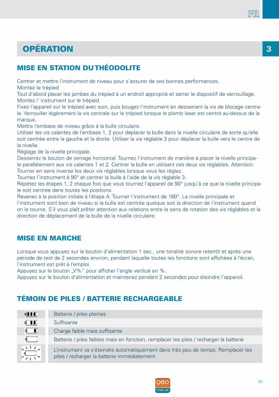
Centrer et mettre l‘instrument de niveau pour s‘assurer de ses bonnes performances.Montez le trépiedTout d‘abord placer les jambes du trépied à un endroit approprié et serrer le dispositif de verrouillage.Montez l‘ instrument sur le trépied.Fixez l‘appareil sur le trépied avec soin, puis bougez l‘instrument en desserrant la vis de blocage centra-le. Verrouiller légèrement la vis centrale sur le trépied lorsque le plomb laser est centré au-dessus de la marque.Mettre l‘embase de niveau grâce à la bulle circulaire.Utiliser les vis calantes de l‘embase 1, 2 pour déplacer la bulle dans la nivelle circulaire de sorte qu‘elle soit centrée entre la gauche et la droite. Utiliser la vis réglable 3 pour déplacer la bulle vers le centre de la nivelle.Réglage de la nivelle principale.Desserrez le bouton de serrage horizontal. Tournez l‘instrument de manière à placer la nivelle principa-le parallèlement aux vis calantes 1 et 2. Centrer la bulle en utilisant ces deux vis réglables. Attention: Tourner en sens inverse les deux vis réglables lorsque vous les réglez.Tournez l‘instrument à 90° et centrer la bulle à l‘aide de la vis réglable 3.Répétez les étapes 1, 2 chaque fois que vous tournez l‘appareil de 90° jusqu‘à ce que la nivelle principa-le soit centrée dans toutes les positions.Revenez à la position initiale à l‘étape A. Tourner l‘instrument de 180°. La nivelle principale et l‘instrument sont bien de niveau si la bulle est centrée quelque soit la direction de l‘instrument quand on le tourne. S‘il vous plaît prêter attention aux relations entre le sens de rotation des vis réglables et la direction de déplacement de la bulle de la nivelle circulaire.
Lorsque vous appuyez sur le bouton d‘alimentation 1 sec., une tonalité sonore retentit et après une période de test de 2 secondes environ, pendant laquelle toutes les fonctions sont affichées à l‘écran, l‘instrument est prêt à l‘emploi.Appuyez sur le bouton „V%“ pour afficher l‘angle vertical en %.Appuyez sur le bouton d‘alimentation et maintenez pendant 2 secondes pour éteindre l‘appareil.
Batterie / piles pleines
Suffisante
Charge faible mais suffisante
Batterie / piles faibles mais en fonction, remplacer les piles / recharger la batterie
L‘instrument va s‘éteindre automatiquement dans trés peu de temps. Remplacer les piles / recharger la batterie immédiatement
3
36
FR
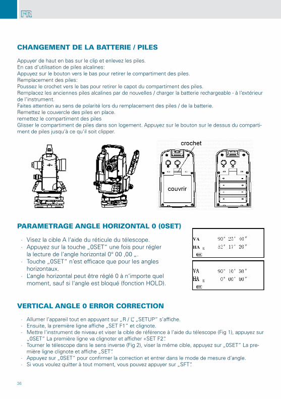
CHANGEMENT DE LA BATTERIE / PILES
PARAMETRAGE ANGLE HORIZONTAL 0 (0SET)
VERTICAL ANGLE 0 ERROR CORRECTION
Appuyer de haut en bas sur le clip et enlevez les piles.En cas d‘utilisation de piles alcalines:Appuyez sur le bouton vers le bas pour retirer le compartiment des piles.Remplacement des piles:Poussez le crochet vers le bas pour retirer le capot du compartiment des piles.Remplacez les anciennes piles alcalines par de nouvelles / charger la batterie rechargeable - à l‘extérieur de l‘instrument. Faites attention au sens de polarité lors du remplacement des piles / de la batterie.Remettez le couvercle des piles en place.remettez le compartiment des pilesGlisser le compartiment de piles dans son logement. Appuyez sur le bouton sur le dessus du comparti-ment de piles jusqu‘à ce qu‘il soit clipper.
∙ Visez la cible A l‘aide du réticule du télescope. ∙ Appuyez sur la touche „0SET“ une fois pour régler
la lecture de l‘angle horizontal 0° 00 ‚00 „. ∙ Touche „0SET“ n‘est efficace que pour les angles
horizontaux. ∙ L‘angle horizontal peut être réglé 0 à n‘importe quel
moment, sauf si l‘angle est bloqué (fonction HOLD).
∙ Allumer l‘appareil tout en appuyant sur „R / L“, „SETUP“ s‘affiche. ∙ Ensuite, la première ligne affiche „SET F1“ et clignote. ∙ Mettre l‘instrument de niveau et viser la cible de référence à l‘aide du télescope (Fig 1), appuyez sur
„0SET“ La première ligne va clignoter et afficher «SET F2“. ∙ Tourner le télescope dans le sens inverse (Fig 2), viser la même cible, appuyez sur „0SET“ La pre-
mière ligne clignote et affiche „SET“. ∙ Appuyez sur „0SET“ pour confirmer la correction et entrer dans le mode de mesure d‘angle. ∙ Si vous voulez quitter à tout moment, vous pouvez appuyer sur „SFT“.
37
FR
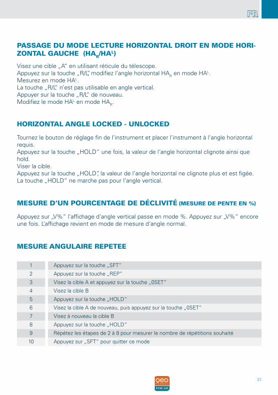
PASSAGE DU MODE LECTURE HORIZONTAL DROIT EN MODE HORI-ZONTAL GAUCHE (HAR/HAL)
HORIZONTAL ANGLE LOCKED - UNLOCKED
MESURE D‘UN POURCENTAGE DE DÉCLIVITÉ (MESURE DE PENTE EN %)
MESURE ANGULAIRE REPETEE
Visez une cible „A“ en utilisant réticule du télescope.Appuyez sur la touche „R/L“, modifiez l‘angle horizontal HAR en mode HAL.Mesurez en mode HAL.La touche „R/L“ n’est pas utilisable en angle vertical.Appuyer sur la touche „R/L“ de nouveau.Modifiez le mode HAL en mode HAR.
Tournez le bouton de réglage fin de l‘instrument et placer l‘instrument à l‘angle horizontal requis.Appuyez sur la touche „HOLD“ une fois, la valeur de l‘angle horizontal clignote ainsi que hold.Viser la cible.Appuyez sur la touche „HOLD“, la valeur de l‘angle horizontal ne clignote plus et est figée.La touche „HOLD“ ne marche pas pour l‘angle vertical.
Appuyez sur „V%“ l‘affichage d‘angle vertical passe en mode %. Appuyez sur „V%“ encore une fois. L‘affichage revient en mode de mesure d‘angle normal.
1 Appuyez sur la touche „SFT“
2 Appuyez sur la touche „REP“
3 Visez la cible A et appuyez sur la touche „0SET“
4 Visez la cible B
5 Appuyez sur la touche „HOLD“
6 Visez la cible A de nouveau, puis appuyez sur la touche „0SET“
7 Visez à nouveau la cible B
8 Appuyez sur la touche „HOLD“
9 Répétez les étapes de 2 à 8 pour mesurer le nombre de répétitions souhaité
10 Appuyez sur „SFT“ pour quitter ce mode
38
FR
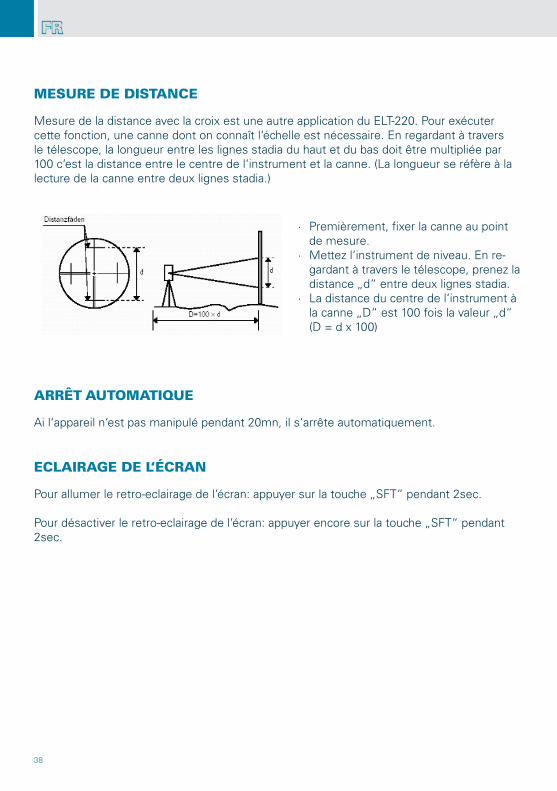
Mesure de la distance avec la croix est une autre application du ELT-220. Pour exécuter cette fonction, une canne dont on connaît l‘échelle est nécessaire. En regardant à travers le télescope, la longueur entre les lignes stadia du haut et du bas doit être multipliée par 100 c‘est la distance entre le centre de l‘instrument et la canne. (La longueur se réfère à la lecture de la canne entre deux lignes stadia.)
Ai l‘appareil n‘est pas manipulé pendant 20mn, il s‘arrête automatiquement.
Pour allumer le retro-eclairage de l‘écran: appuyer sur la touche „SFT“ pendant 2sec.
Pour désactiver le retro-eclairage de l‘écran: appuyer encore sur la touche „SFT“ pendant 2sec.
MESURE DE DISTANCE
ARRÊT AUTOMATIQUE
ECLAIRAGE DE L‘ÉCRAN
∙ Premièrement, fixer la canne au point de mesure.
∙ Mettez l‘instrument de niveau. En re-gardant à travers le télescope, prenez la distance „d“ entre deux lignes stadia.
∙ La distance du centre de l‘instrument à la canne „D“ est 100 fois la valeur „d“ (D = d x 100)
39
FR
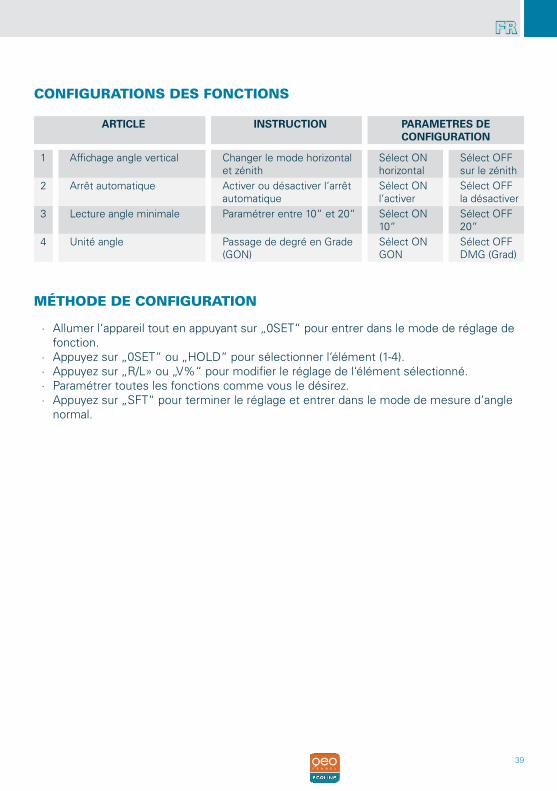
∙ Allumer l‘appareil tout en appuyant sur „0SET“ pour entrer dans le mode de réglage de fonction.
∙ Appuyez sur „0SET“ ou „HOLD“ pour sélectionner l‘élément (1-4). ∙ Appuyez sur „R/L» ou „V%“ pour modifier le réglage de l‘élément sélectionné. ∙ Paramétrer toutes les fonctions comme vous le désirez. ∙ Appuyez sur „SFT“ pour terminer le réglage et entrer dans le mode de mesure d‘angle
normal.
CONFIGURATIONS DES FONCTIONS
MÉTHODE DE CONFIGURATION
ARTICLE INSTRUCTION PARAMETRES DECONFIGURATION
1 Affichage angle vertical Changer le mode horizontal et zénith
Sélect ONhorizontal
Sélect OFFsur le zénith
2 Arrêt automatique Activer ou désactiver l‘arrêt automatique
Sélect ONl‘activer
Sélect OFFla désactiver
3 Lecture angle minimale Paramétrer entre 10“ et 20“ Sélect ON10“
Sélect OFF20“
4 Unité angle Passage de degré en Grade (GON)
Sélect ONGON
Sélect OFFDMG (Grad)
40
FR
TECHNICAL SPECIFICATIONS
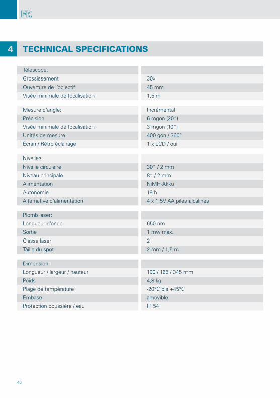
Télescope:
Grossissement 30x
Ouverture de l‘objectif 45 mm
Visée minimale de focalisation 1,5 m
Mesure d‘angle: Incrémental
Précision 6 mgon (20“)
Visée minimale de focalisation 3 mgon (10“)
Unités de mesure 400 gon / 360°
Écran / Rétro éclairage 1 x LCD / oui
Nivelles:
Nivelle circulaire 30“ / 2 mm
Niveau principale 8“ / 2 mm
Alimentation NiMH-Akku
Autonomie 18 h
Alternative d‘alimentation 4 x 1,5V AA piles alcalines
Plomb laser:
Longueur d‘onde 650 nm
Sortie 1 mw max.
Classe laser 2
Taille du spot 2 mm / 1,5 m
Dimension:
Longueur / largeur / hauteur 190 / 165 / 345 mm
Poids 4,8 kg
Plage de température -20°C bis +45°C
Embase amovible
Protection poussière / eau IP 54
4
41
FR
CONSIGNES DE SÉCURITÉ
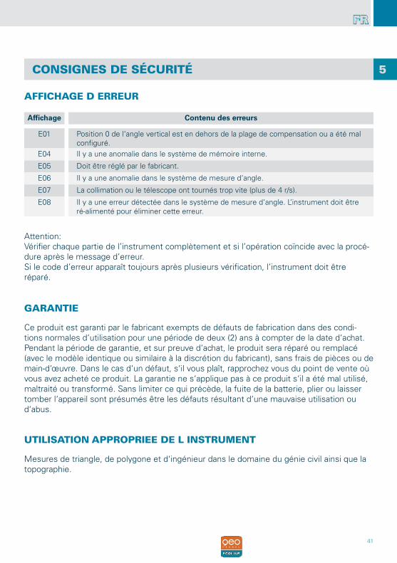
AFFICHAGE D ERREUR
Affichage Contenu des erreurs
E01 Position 0 de l‘angle vertical est en dehors de la plage de compensation ou a été mal configuré.
E04 Il y a une anomalie dans le système de mémoire interne.
E05 Doit être réglé par le fabricant.
E06 Il y a une anomalie dans le système de mesure d‘angle.
E07 La collimation ou le télescope ont tournés trop vite (plus de 4 r/s).
E08 Il y a une erreur détectée dans le système de mesure d‘angle. L‘instrument doit être ré-alimenté pour éliminer cette erreur.
GARANTIE
Ce produit est garanti par le fabricant exempts de défauts de fabrication dans des condi-tions normales d‘utilisation pour une période de deux (2) ans à compter de la date d‘achat. Pendant la période de garantie, et sur preuve d‘achat, le produit sera réparé ou remplacé (avec le modèle identique ou similaire à la discrétion du fabricant), sans frais de pièces ou de main-d‘œuvre. Dans le cas d‘un défaut, s‘il vous plaît, rapprochez vous du point de vente où vous avez acheté ce produit. La garantie ne s‘applique pas à ce produit s‘il a été mal utilisé, maltraité ou transformé. Sans limiter ce qui précède, la fuite de la batterie, plier ou laisser tomber l‘appareil sont présumés être les défauts résultant d‘une mauvaise utilisation ou d‘abus.
5
UTILISATION APPROPRIEE DE L INSTRUMENT
Mesures de triangle, de polygone et d‘ingénieur dans le domaine du génie civil ainsi que la topographie.
Attention:Vérifier chaque partie de l’instrument complètement et si l’opération coïncide avec la procé-dure après le message d’erreur.Si le code d’erreur apparaît toujours après plusieurs vérification, l’instrument doit êtreréparé.
42
FR
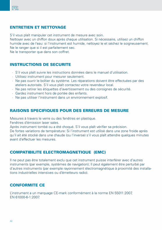
ENTRETIEN ET NETTOYAGE
CONFORMITE CE
INSTRUCTIONS DE SECURITE
RAISONS SPECIFIQUES POUR DES ERREURS DE MESURE
COMPATIBILITE ELECTROMAGNETIQUE (EMC)
S‘il vous plaît manipuler cet instrument de mesure avec soin.Nettoyer avec un chiffon doux après chaque utilisation. Si nécessaire, utilisez un chiffon humide avec de l‘eau: si l‘instrument est humide, nettoyez le et séchez le soigneusement.Ne le ranger que si il est parfaitement sec.Ne le transporter que dans son coffret.
Il ne peut pas être totalement exclu que cet instrument puisse interférer avec d‘autres instruments (par exemple, systèmes de navigation); Il peut également être perturbé par d‘autres instruments (par exemple rayonnement électromagnétique à proximité des installa-tions industrielles intensives ou d‘émetteurs radio).
L‘instrument a un marquage CE-mark conformément à la norme EN 55011:2007,EN 61000-6-1:2007.
∙ S‘il vous plaît suivre les instructions données dans le manuel d‘utilisation. ∙ Utilisez instrument pour mesurer seulement. ∙ Ne pas ouvrir le boîtier du système. Les réparations doivent être effectuées par des
ateliers autorisés. S‘il vous plaît contactez votre revendeur local. ∙ Ne pas retirer les étiquettes d‘avertissement ou des consignes de sécurité. ∙ Gardez instrument hors de portée des enfants. ∙ Ne pas utiliser l‘instrument dans un environnement explosif.
Mesures à travers le verre ou des fenêtres en plastique.Fenêtres d‘émission laser sales.Après instrument tombé ou a été choqué. S‘il vous plaît vérifier sa précision.De fortes variations de température: Si l‘instrument est utilisé dans une zone froide après qu‘il ait été stocké dans une chaude (ou l‘inverse) s‘il vous plaît attendre quelques minutes avant d‘effectuer les mesures.
43
FR
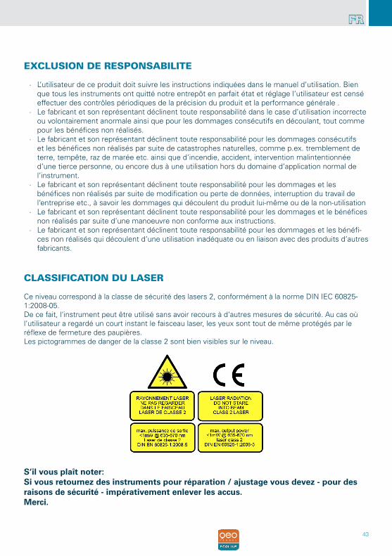
EXCLUSION DE RESPONSABILITE
∙ L‘utilisateur de ce produit doit suivre les instructions indiquées dans le manuel d‘utilisation. Bien que tous les instruments ont quitté notre entrepôt en parfait état et réglage l‘utilisateur est censé effectuer des contrôles périodiques de la précision du produit et la performance générale .
∙ Le fabricant et son représentant déclinent toute responsabilité dans le case d‘utilisation incorrecte ou volontairement anormale ainsi que pour les dommages consécutifs en découlant, tout comme pour les bénéfices non réalisés.
∙ Le fabricant et son représentant déclinent toute responsabilité pour les dommages consécutifs et les bénéfices non réalisés par suite de catastrophes naturelles, comme p.ex. tremblement de terre, tempête, raz de marée etc. ainsi que d‘incendie, accident, intervention malintentionnée d‘une tierce personne, ou encore dus à une utilisation hors du domaine d‘application normal de l‘instrument.
∙ Le fabricant et son représentant déclinent toute responsabilité pour les dommages et les bénéfices non réalisés par suite de modification ou perte de données, interruption du travail de l‘entreprise etc., à savoir les dommages qui découlent du produit lui-même ou de la non-utilisation
∙ Le fabricant et son représentant déclinent toute responsabilité pour les dommages et le bénéfices non réalisés par suite d‘une manoeuvre non conforme aux instructions.
∙ Le fabricant et son représentant déclinent toute responsabilité pour les dommages et les bénéfi-ces non réalisés qui découlent d‘une utilisation inadéquate ou en liaison avec des produits d‘autres fabricants.
CLASSIFICATION DU LASER
Ce niveau correspond à la classe de sécurité des lasers 2, conformément à la norme DIN IEC 60825- 1:2008-05. De ce fait, l‘instrument peut être utilisé sans avoir recours à d‘autres mesures de sécurité. Au cas où l‘utilisateur a regardé un court instant le faisceau laser, les yeux sont tout de même protégés par le réflexe de fermeture des paupières.Les pictogrammes de danger de la classe 2 sont bien visibles sur le niveau.
S‘il vous plaît noter:Si vous retournez des instruments pour réparation / ajustage vous devez - pour des raisons de sécurité - impérativement enlever les accus. Merci.

Technische Änderungen vorbehalten.All instruments subject to technical changes.
Sous réserve de modifications techniques.
11/2013


![LOTUS ELISE 220 CUP - Lotus am Ringlotus-am-ring.de/Elise-220-Cup.pdf · LOTUSCARS.COM ELISE 220 CUP TECHNISCHE DATEN LEISTUNG Max. Leistung 220 PS [162 kW] bei 6.800 U\min Max. Drehmoment](https://img.pdfslide.org/doc/110x75/5a9e1fca7f8b9ad2298d9ae2/lotus-elise-220-cup-lotus-am-ringlotus-am-ringdeelise-220-cup-elise-220-cup.jpg)