Embed Size (px)
Citation preview
7/28/2019 Sauer90-ServiceManual.pdf
http://slidepdf.com/reader/full/sauer90-servicemanualpdf 1/72
Series 90 Pumps
Service Manual
7/28/2019 Sauer90-ServiceManual.pdf
http://slidepdf.com/reader/full/sauer90-servicemanualpdf 2/72
2 520L0818 • Rev AB • April 2008
Series 90 Axial Piston Closed Circuit Pumps
Service Manual
© 2008 Sauer-Danfoss. All rights reserved.
Sauer-Danfoss accepts no responsibility for possible errors in catalogs, brochures and other printed material.
Sauer-Danfoss reserves the right to alter its products without prior notice. This also applies to products
already ordered provided that such alterations aren’t in conict with agreed specications. All trademarks in
this material are properties of their respective owners. Sauer-Danfoss and the Sauer-Danfoss logotype are
trademarks of the Sauer-Danfoss Group.
Front cover illustrations: F000539, F300856, F101411
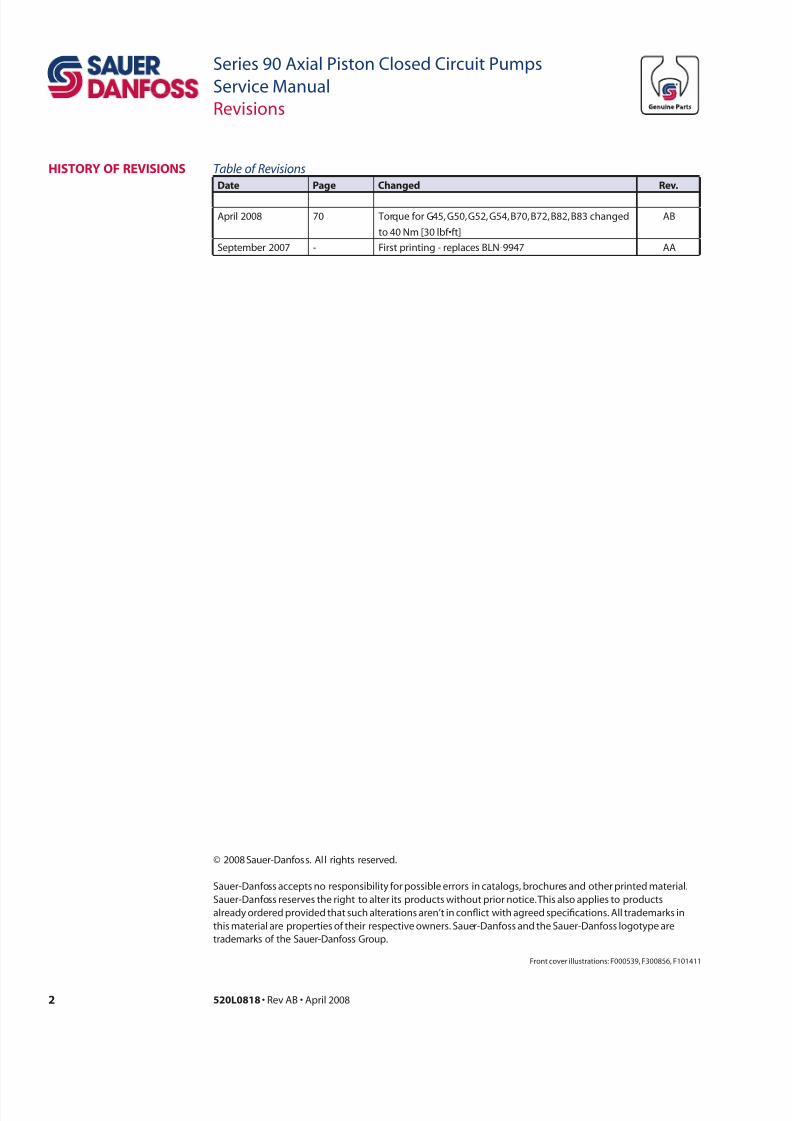
Revisions
Table o Revisions
D P Chd R.
April 2008 70 Torque for G45, G50, G52, G54, B70, B72, B82, B83 changed
to 40 Nm [30 lbf•ft]
AB
September 2007 - First printing - replaces BLN-9947 AA
HistoRy o Revisions
7/28/2019 Sauer90-ServiceManual.pdf
http://slidepdf.com/reader/full/sauer90-servicemanualpdf 3/72
3520L0818 • Rev AB • April 2008
Series 90 Axial Piston Closed Circuit Pumps
Service Manual
Contents
intRoDuCtion
oPeRation
oPeRating
PaRameteRs
teCHniCaL
sPeCiiCations
Overview ...........................................................................................................................................................6
Warranty ............................................................................................................................................................6
General instructions ...................................................................................................................................... 6Safety precautions .........................................................................................................................................7
Unintended machine movement .......................................................................................................7
Flammable cleaning solvents ............................................................................................................... 7
Fluid under pressure ................................................................................................................................7
Personal safety ...........................................................................................................................................7
Symbols used in Sauer-Danfoss literature.............................................................................................8
Design ................................................................................................................................................................9
The system circuit.........................................................................................................................................10
Charge pump .................................................................................................................................................12
Charge relief valve........................................................................................................................................12Multi-function valves ..................................................................................................................................12
Pressure limiter and high pressure relief valves ................................................................................13
System check valves ....................................................................................................................................13
Bypass valves .................................................................................................................................................13
Speed sensors ................................................................................................................................................13
Filtration options ..........................................................................................................................................14
Pressure override (POR) – 180 frame size only ...................................................................................14
Manual displacement control (MDC) ....................................................................................................15
Non-linear MDC ............................................................................................................................................15
Solenoid override valve for MDC ............................................................................................................15
Neutral start switch (NSS) ..........................................................................................................................15
Hydraulic displacement control (HDC) .................................................................................................15
Electric displacement control (EDC) ......................................................................................................15
Automotive control (FBA II B)...................................................................................................................15
3-Position (FNR) electric control .............................................................................................................15
Overview .........................................................................................................................................................16
Input speed ....................................................................................................................................................16
System pressure ............................................................................................................................................16
Charge pressure ............................................................................................................................................17
Charge inlet pressure ..................................................................................................................................17
Case pressure .................................................................................................................................................17
Temperature and viscosity ........................................................................................................................18
Temperature .............................................................................................................................................18Viscosity......................................................................................................................................................18
Fluid and lter recommendations ..........................................................................................................19
Overview .........................................................................................................................................................20
Features and options ..................................................................................................................................20
Operating parameters ................................................................................................................................20
Fluid specications ......................................................................................................................................20
7/28/2019 Sauer90-ServiceManual.pdf
http://slidepdf.com/reader/full/sauer90-servicemanualpdf 4/72
4 520L0818 • Rev AB • April 2008
Series 90 Axial Piston Closed Circuit Pumps
Service Manual
Contents
initiaL staRtuP
PRoCeDuRes
PRessuRe
measuRements
tRoubLesHooting
aDjustments
General ............................................................................................................................................................21
Start-up procedure ......................................................................................................................................21
Required tools ...............................................................................................................................................23
Port locations and gauge installation ...................................................................................................23
Overview .........................................................................................................................................................26
Neutral difcult or impossible to nd ...................................................................................................26
System operating hot .................................................................................................................................26
Transmission operates normally in one direction only ..................................................................27
System will not operate in either direction.........................................................................................27
Low motor output torque .........................................................................................................................28
Improper motor output speed ................................................................................................................28System noise or vibration ..........................................................................................................................28
System response is sluggish .....................................................................................................................29
Standard procedures, inspections, and adjustments ......................................................................30
Adjustments ...................................................................................................................................................31
Charge pressure relief valve adjustment .............................................................................................31
Multi-function valve pressure adjustment ..........................................................................................33
Engaging the bypass function.................................................................................................................35
Pressure override (POR) valve pressure adjustment (option for 180 frame size) ..................36
Displacement limiter adjustment ...........................................................................................................37
Standard manual displacement control (MDC) adjustment.........................................................37
Non-linear manual displacement control (MDC) ..............................................................................38
MDC neutral start switch (NSS) adjustments .....................................................................................39
Neutral start switch eccentric plug adjustment (condition i) .................................................41
NSS deadband adjustment (conditions ii & iii) .............................................................................42
Checking switch continuity ......................................................................................................................44
Hydraulic displacement control (HDC) and electric displacement control (EDC)
adjustment .....................................................................................................................................................45
Speed sensor adjustment..........................................................................................................................46
7/28/2019 Sauer90-ServiceManual.pdf
http://slidepdf.com/reader/full/sauer90-servicemanualpdf 5/72
5520L0818 • Rev AB • April 2008
Series 90 Axial Piston Closed Circuit Pumps
Service Manual
Contents
minoR RePaiR
toRque CHaRt
Standard procedures ..................................................................................................................................47
Shaft seal and shaft replacement ...........................................................................................................48
Multi-function valve cartridges ...............................................................................................................50Multi-function valve cartridges - pre 1988 ..........................................................................................52
Pressure override valve (option for 180 frame size) .........................................................................53
Charge pressure relief valve .....................................................................................................................54
Auxiliary pad ..................................................................................................................................................55
Charge pump .................................................................................................................................................56
Adding an Auxiliary pad to a pump previously without one .......................................................58
Integral charge pressure lter replacement .......................................................................................59
Pump control cover plate ..........................................................................................................................60
Displacement control orices ..................................................................................................................61
Displacement control orice check valve ...........................................................................................61
Displacement control adapter plate (early production 130 pumps only) ...............................61
Manual displacement control (MDC) ....................................................................................................62Solenoid override valve for MDC ............................................................................................................63
Solenoid override valve for MDC with pressure released brake .................................................64
Hydraulic and electric displacement controls ...................................................................................65
Pressure control pilot (PCP) for electric displacement control (EDC) ........................................66
3-Position (FNR) electric control .............................................................................................................67
Displacement control lter screens .......................................................................................................68
Speed sensor ..................................................................................................................................................68
Fastener size and torque chart ................................................................................................................69
Plug size and torque chart ........................................................................................................................70
Fasteners and plugs .....................................................................................................................................70
7/28/2019 Sauer90-ServiceManual.pdf
http://slidepdf.com/reader/full/sauer90-servicemanualpdf 6/72
6 520L0818 • Rev AB • April 2008
Series 90 Axial Piston Closed Circuit Pumps
Service Manual
Introduction
oveRview
Follow these general procedures when repairing Series 90 variable displacement closed
circuit pumps.
wRemove the unit
Prior to performing major repairs, remove the unit from the vehicle/machine. Chock
the wheels on the vehicle or lock the mechanism to inhibit movement. Be aware that
hydraulic uid may be under high pressure and/or hot. Inspect the outside of the pump
and ttings for damage. Cap hoses after removal to prevent contamination.
e Keep it clean
Cleanliness is a primary means of assuring satisfactory pump life, on either new or
repaired units. Clean the outside of the pump thoroughly before disassembly. Take care
to avoid contamination of the system ports. Cleaning parts by using a clean solvent wash
and air drying is usually adequate.
As with any precision equipment, keep all parts free of foreign materials and chemicals.
Protect all exposed sealing surfaces and open cavities from damage and foreign material.If left unattended, cover the pump with a protective layer of plastic.
d Replace all O-rings and gaskets
Use new O-rings and gaskets during reassembly. Lightly lubricate all O-rings with clean
petroleum jelly prior to assembly.
t Secure the unit
For repair, place the unit in a stable position with the shaft pointing downward. It will be
necessary to secure the pump while removing and torquing end covers, controls, and
valves.
geneRaL instRuCtions
waRRanty Performing installation, maintenance, and minor repairs according to the procedures in
this manual will not affect your warranty. Major repairs requiring the removal of a unit’s
rear or side cover voids the warranty unless done by a Sauer-Danfoss Authorized Service
Center.
This manual includes information for the installation, maintenance, and minor repair of
Series 90 axial piston closed circuit pumps. It includes a description of the unit and its
individual components, troubleshooting information, and minor repair procedures.
Performing minor repairs requires you remove the unit from the vehicle/machine.
Thoroughly clean the unit before beginning maintenance or repair activities. Since dirt
and contamination are the greatest enemies of any type of hydraulic equipment, follow
cleanliness requirements strictly. This is especially important when changing the system
lter and when removing hoses or plumbing.
A worldwide network of Sauer-Danfoss Global Service Partners (GSPs) is available for
major repairs. Sauer-Danfoss trains GSPs and certies their facilities on a regular basis.
You can locate your nearest ASC using the distributor locator at www.sauer-danfoss.com.
Click on the Sales and Service link.
7/28/2019 Sauer90-ServiceManual.pdf
http://slidepdf.com/reader/full/sauer90-servicemanualpdf 7/72
7520L0818 • Rev AB • April 2008
Series 90 Axial Piston Closed Circuit Pumps
Service Manual
Introduction
saety PReCautions Always consider safety precautions before beginning a service procedure. Protect
yourself and others from injury. Take the following general precautions whenever servicing a
hydraulic system.
udd ch
W wr
Unintended movement of the machine or mechanism may cause injury to the technician
or bystanders. To protect against unintended movement, secure the machine or disable/
disconnect the mechanism while servicing.
ll cl l
W wr
Some cleaning solvents are ammable. To avoid possible re, do not use cleaning
solvents in an area where a source of ignition may be present.
ld dr prr
W wr
Escaping hydraulic uid under pressure can have sufcient force to penetrate your skin
causing serious injury and/or infection. This uid may also be hot enough to cause burns.
Use caution when dealing with hydraulic uid under pressure. Relieve pressure in the
system before removing hoses, ttings, gauges, or components. Never use your hand
or any other body part to check for leaks in a pressurized line. Seek medical attention
immediately if you are cut by hydraulic uid.
Prl
W wr
Protect yourself from injury. Use proper safety equipment, including safety glasses, at all
times.
7/28/2019 Sauer90-ServiceManual.pdf
http://slidepdf.com/reader/full/sauer90-servicemanualpdf 8/72
8 520L0818 • Rev AB • April 2008
Series 90 Axial Piston Closed Circuit Pumps
Service Manual
Introduction
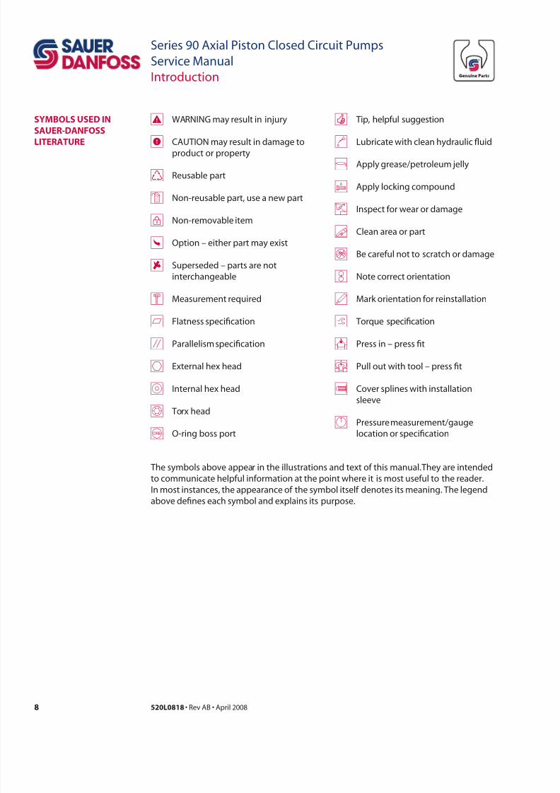
WARNING may result in injury
CAUTION may result in damage toproduct or property
Reusable part
Non-reusable part, use a new part
Non-removable item
Option – either part may exist
Superseded – parts are not
interchangeable
Measurement required
Flatness specication
Parallelism specication
External hex head
Internal hex head
Torx head
O-ring boss port
Tip, helpful suggestion
Lubricate with clean hydraulic uid
Apply grease/petroleum jelly
Apply locking compound
Inspect for wear or damage
Clean area or part
Be careful not to scratch or damage
Note correct orientation
Mark orientation for reinstallation
Torque specication
Press in – press t
Pull out with tool – press t
Cover splines with installation
sleeve
Pressure measurement/gauge
location or specication
symboLs useD in
saueR-Danoss
LiteRatuRe
The symbols above appear in the illustrations and text of this manual. They are intended
to communicate helpful information at the point where it is most useful to the reader.
In most instances, the appearance of the symbol itself denotes its meaning. The legend
above denes each symbol and explains its purpose.
7/28/2019 Sauer90-ServiceManual.pdf
http://slidepdf.com/reader/full/sauer90-servicemanualpdf 9/72
9520L0818 • Rev AB • April 2008
Series 90 Axial Piston Closed Circuit Pumps
Service Manual
Introduction
Design
P106 648E
Slider block Servo piston
Servo arm
Displacement control
Cradle bearing
Charge pump Swashplate Cradle guide
Feedback linkage
Roller bearing
Shaft
PistonSlipper
Valve plate
Cylinder block
Input shaft
Rear
bushing
Bushing
seal
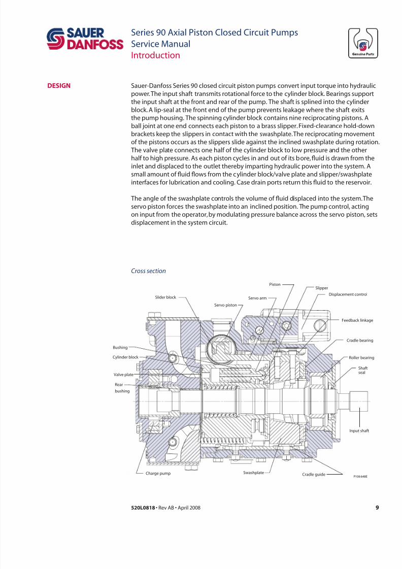
Cross section
Sauer-Danfoss Series 90 closed circuit piston pumps convert input torque into hydraulic
power. The input shaft transmits rotational force to the cylinder block. Bearings support
the input shaft at the front and rear of the pump. The shaft is splined into the cylinderblock. A lip-seal at the front end of the pump prevents leakage where the shaft exits
the pump housing. The spinning cylinder block contains nine reciprocating pistons. A
ball joint at one end connects each piston to a brass slipper. Fixed-clearance hold-down
brackets keep the slippers in contact with the swashplate. The reciprocating movement
of the pistons occurs as the slippers slide against the inclined swashplate during rotation.
The valve plate connects one half of the cylinder block to low pressure and the other
half to high pressure. As each piston cycles in and out of its bore, uid is drawn from the
inlet and displaced to the outlet thereby imparting hydraulic power into the system. A
small amount of uid ows from the cylinder block/valve plate and slipper/swashplate
interfaces for lubrication and cooling. Case drain ports return this uid to the reservoir.
The angle of the swashplate controls the volume of uid displaced into the system. Theservo piston forces the swashplate into an inclined position. The pump control, acting
on input from the operator, by modulating pressure balance across the servo piston, sets
displacement in the system circuit.
7/28/2019 Sauer90-ServiceManual.pdf
http://slidepdf.com/reader/full/sauer90-servicemanualpdf 10/72
10 520L0818 • Rev AB • April 2008
Series 90 Axial Piston Closed Circuit Pumps
Service Manual
Introduction
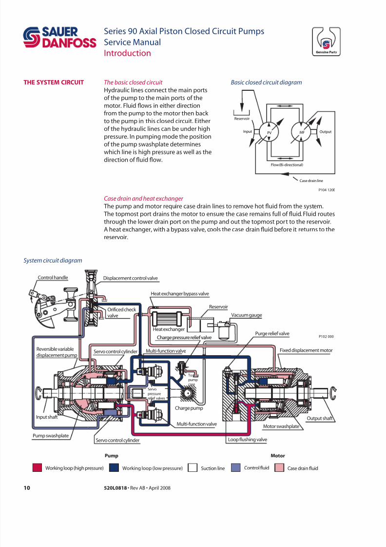
tHe system CiRCuit The basic closed circuit
Hydraulic lines connect the main ports
of the pump to the main ports of themotor. Fluid ows in either direction
from the pump to the motor then back
to the pump in this closed circuit. Either
of the hydraulic lines can be under high
pressure. In pumping mode the position
of the pump swashplate determines
which line is high pressure as well as the
direction of uid ow.
Case drain and heat exchanger
The pump and motor require case drain lines to remove hot uid from the system.
The topmost port drains the motor to ensure the case remains full of uid. Fluid routes
through the lower drain port on the pump and out the topmost port to the reservoir.
A heat exchanger, with a bypass valve, cools the case drain uid before it returns to the
reservoir.
Pump Motor
Working loop (low pressure) Control fluidSuction line Case drain fluidWorking loop (high pressure)
Motor swashplate
Loop flushing valve
Displacement control valve
Heat exchanger bypass valve
Reservoir
Vacuum gauge
Purge relief valve
Fixed displacement motor
Output shaftMulti-function valve
Charge pump
Topump
caseServopressurerelief valves
Servo control cylinderPump swashplate
Input shaft
Reversible variabledisplacement pump
Servo control cylinder
Heat exchanger
Multi-function valve
Charge pressure relief valve
Orificed check valve
Control handle
P102 000
Input PV MF
Case drain line
Output
Flow (Bi-directional)
Reservoir
P104 120E
Basic closed circuit diagram
System circuit diagram
7/28/2019 Sauer90-ServiceManual.pdf
http://slidepdf.com/reader/full/sauer90-servicemanualpdf 11/72
11520L0818 • Rev AB • April 2008
Series 90 Axial Piston Closed Circuit Pumps
Service Manual
Introduction
P104 126E
M4
M5
L2SL1
X5
M1
M2
A
B
M3
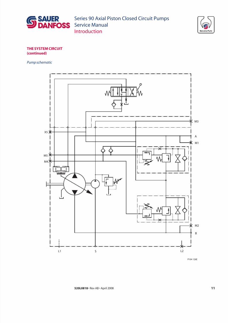
tHe system CiRCuit
(cd)
Pump schematic
7/28/2019 Sauer90-ServiceManual.pdf
http://slidepdf.com/reader/full/sauer90-servicemanualpdf 12/72
12 520L0818 • Rev AB • April 2008
Series 90 Axial Piston Closed Circuit Pumps
Service Manual
Operation
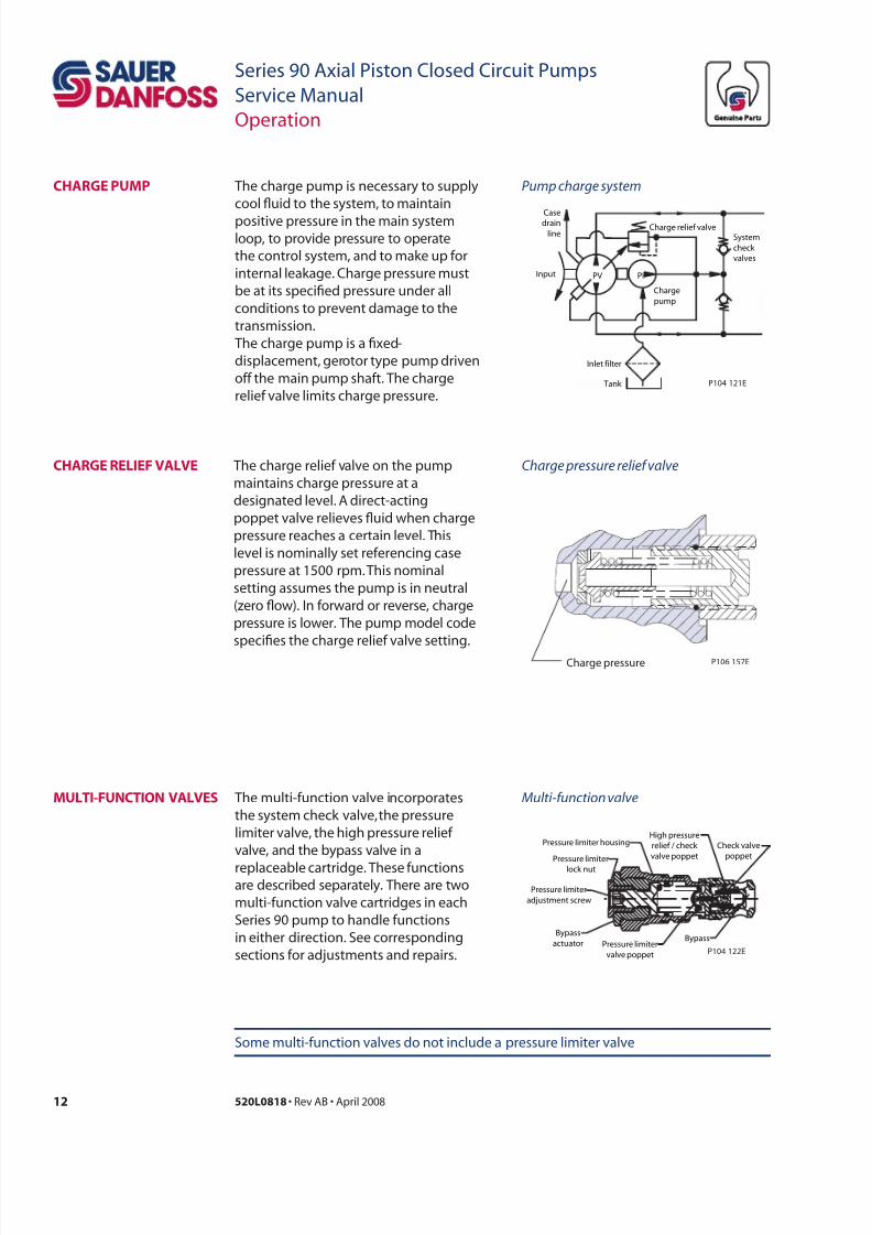
CHaRge PumP The charge pump is necessary to supply
cool uid to the system, to maintain
positive pressure in the main systemloop, to provide pressure to operate
the control system, and to make up for
internal leakage. Charge pressure must
be at its specied pressure under all
conditions to prevent damage to the
transmission.
The charge pump is a xed-
displacement, gerotor type pump driven
off the main pump shaft. The charge
relief valve limits charge pressure.
CHaRge ReLie vaLve The charge relief valve on the pump
maintains charge pressure at a
designated level. A direct-acting
poppet valve relieves uid when charge
pressure reaches a certain level. This
level is nominally set referencing case
pressure at 1500 rpm. This nominal
setting assumes the pump is in neutral
(zero ow). In forward or reverse, charge
pressure is lower. The pump model code
species the charge relief valve setting.
muLti-unCtion vaLves The multi-function valve incorporates
the system check valve, the pressure
limiter valve, the high pressure relief
valve, and the bypass valve in a
replaceable cartridge. These functionsare described separately. There are two
multi-function valve cartridges in each
Series 90 pump to handle functions
in either direction. See corresponding
sections for adjustments and repairs.
Some multi-function valves do not include a pressure limiter valve
Casedrain
lineCharge relief valve
Charge
pump
System
check
valves
Input
Inlet filter
Tank
PV PF
P104 121E
Pump charge system
Multi-unction valve
High pressure
relief / check
valve poppet
Pressure limiter
valve poppet
Bypass
actuator
Pressure limiter
adjustment screw
Pressure limiter
lock nut
Pressure limiter housing Check valve
poppet
Bypass
P104 122E
Charge pressure P106 157E
Charge pressure relie valve
7/28/2019 Sauer90-ServiceManual.pdf
http://slidepdf.com/reader/full/sauer90-servicemanualpdf 13/72
13520L0818 • Rev AB • April 2008
Series 90 Axial Piston Closed Circuit Pumps
Service Manual
Operation
PRessuRe LimiteR anD
HigH PRessuRe ReLie
vaLves
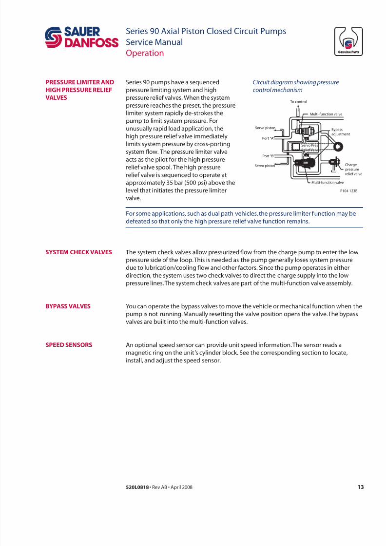
Series 90 pumps have a sequenced
pressure limiting system and high
pressure relief valves. When the systempressure reaches the preset, the pressure
limiter system rapidly de-strokes the
pump to limit system pressure. For
unusually rapid load application, the
high pressure relief valve immediately
limits system pressure by cross-porting
system ow. The pressure limiter valve
acts as the pilot for the high pressure
relief valve spool. The high pressure
relief valve is sequenced to operate at
approximately 35 bar (500 psi) above the
level that initiates the pressure limitervalve.
For some applications, such as dual path vehicles, the pressure limiter function may be
defeated so that only the high pressure relief valve function remains.
system CHeCk vaLves The system check valves allow pressurized ow from the charge pump to enter the low
pressure side of the loop. This is needed as the pump generally loses system pressure
due to lubrication/cooling ow and other factors. Since the pump operates in either
direction, the system uses two check valves to direct the charge supply into the low
pressure lines. The system check valves are part of the multi-function valve assembly.
byPass vaLves You can operate the bypass valves to move the vehicle or mechanical function when the
pump is not running. Manually resetting the valve position opens the valve. The bypass
valves are built into the multi-function valves.
Circuit diagram showing pressure
control mechanism
Servo Pres.
Relief Valve
Charge
pressure
relief valve
Multi-function valve
Multi-function valve
To control
Servo piston
Servo piston
Port "A"
Port "B"
Bypass
adjustment
P104 123E
An optional speed sensor can provide unit speed information. The sensor reads a
magnetic ring on the unit’s cylinder block. See the corresponding section to locate,
install, and adjust the speed sensor.
sPeeD sensoRs
7/28/2019 Sauer90-ServiceManual.pdf
http://slidepdf.com/reader/full/sauer90-servicemanualpdf 14/72
14 520L0818 • Rev AB • April 2008
Series 90 Axial Piston Closed Circuit Pumps
Service Manual
Operation
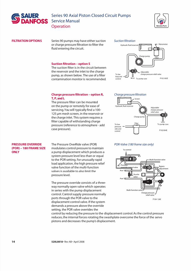
iLtRation oPtions Series 90 pumps may have either suction
or charge pressure ltration to lter the
uid entering the circuit.
To pump case
Charge pump
Hydraulic fluid reservoir
Filter To lowpressureside andcontrol
Screen
Adjustablecharge pressurerelief valve
P102 004E
Charge pumpFilter
Hydraulic fluid reservoir
Adjustablecharge pressure relief valve
To pump case
To lowloop andcontrol
Manometer
P102 003E
Suction fltration
Charge pressure fltration
The Pressure OverRide valve (POR)
modulates control pressure to maintain
a pump displacement which produces a
system pressure level less than or equal
to the POR setting. For unusually rapid
load application, the high pressure relief
valve function of the multi-function
valves is available to also limit the
pressure level.
The pressure override consists of a three-
way normally open valve which operates
in series with the pump displacementcontrol. Control supply pressure normally
ports through the POR valve to the
displacement control valve. If the system
demands a pressure above the override
setting, the POR valve overrides the
PRessuRe oveRRiDe
(PoR) – 180 Rame size
onLy
POR-Valve (180 rame size only)
Shuttle
valve
Multi-function valve
Multi-function valve
Bypass
adjustment
Charge pressure
relief valve
Pressure
override control valve
To control
Port "A"
Port "B"
P104 124E
control by reducing the pressure to the displacement control. As the control pressure
reduces, the internal forces rotating the swashplate overcome the force of the servo
pistons and decreases the pump’s displacement.
sc flr – p s
The suction lter is in the circuit between
the reservoir and the inlet to the charge
pump, as shown below. The use of a lter
contamination monitor is recommended.
Chr prr flr – p R,t, P, d L
The pressure lter can be mounted
on the pump or remotely for ease of
servicing. You will typically nd a 100-
125 µm mesh screen, in the reservoir or
the charge inlet. This system requires a
lter capable of withstanding charge
pressure (reference to atmosphere - add
case pressure).
7/28/2019 Sauer90-ServiceManual.pdf
http://slidepdf.com/reader/full/sauer90-servicemanualpdf 15/72
15520L0818 • Rev AB • April 2008
Series 90 Axial Piston Closed Circuit Pumps
Service Manual
Operation
The manual displacement control converts a mechanical input signal to a hydraulic
signal using a spring-centered four-way servo valve. This valve ports hydraulic pressure
to either side of a dual-acting servo piston. The servo piston rotates the cradleswashplate through an angular rotation of ±17°, varying the pump’s displacement from
full in one direction to full in the opposite direction.The angular position of the pump
swashplate is proportional to the rotation of the control input shaft.
manuaL DisPLaCement
ContRoL (mDC)
The hydraulic displacement control uses a hydraulic input signal to operate a spring-
centered four-way servo valve. This valve ports hydraulic pressure to either side of a
dual-acting servo piston. The servo piston rotates the cradle swashplate through an
angular rotation of ±17°, thus varying the pump’s displacement from full displacement in
one direction to full displacement in the opposite direction. The angular position of the
pump swashplate is proportional to input pressure.
non-LineaR mDC The non-linear manual displacement control operates in the same manner except that it
is designed so the change in the angular position of the pump swashplate progressively
increases as the control input shaft is rotated toward its maximum displacement position.
soLenoiD oveRRiDe
vaLve oR mDC
A solenoid override valve option is available for the MDC. This safety feature returns the
swashplate to zero displacement. It is available in normally open (activate to allow) ornormally closed (activate to disallow) options..
neutRaL staRt switCH
(nss)
The neutral start switch is an optional feature available with the MDC. When connected
properly with the vehicle’s electrical system, the neutral start switch ensures that the
prime mover can start only when the control is in neutral position.
HyDRauLiC
DisPLaCement
ContRoL (HDC)
eLeCtRiC DisPLaCement
ContRoL (eDC)
The electric displacement control uses a Pressure Control Pilot (PCP) valve to modulate
pressure balance across the spring-centered four-way servo valve. The PCP valve
converts a DC electrical input signal to a hydraulic signal. The servo valve ports hydraulic
pressure to either side of a dual-acting servo piston. The servo piston rotates the
swashplate through an angular rotation of ±17°, varying the pump’s displacement. The
angular position of the swashplate is proportional to the EDC input.
automotive ContRoL(ba ii b)
The automotive control allows the operator to drive a vehicle similar to an automobilewith an automatic transmission. The automotive control includes a three-position
electric control to provide direction control.
3-Position (nR)
eLeCtRiC ContRoL
This control utilizes a 12 or 24 Vdc electrically operated spool valve to port pressure to
either side of the pump servo piston. Energizing one of the solenoids causes the pump
to go to its maximum displacement in the corresponding direction. All functions of the
three-position (FNR) electric control are preset at the factory
7/28/2019 Sauer90-ServiceManual.pdf
http://slidepdf.com/reader/full/sauer90-servicemanualpdf 16/72
16 520L0818 • Rev AB • April 2008
Series 90 Axial Piston Closed Circuit Pumps
Service Manual
Operating parameters
oveRview This section denes the operating parameters and limitations for Series 90 pumps with
regard to input speeds and pressures. For actual parameters, refer to the operating
parameters for each displacement.
m pd is the lowest input speed recommended during engine idle condition.
Operating below minimum speed limits the pump’s ability to maintain adequate ow for
lubrication and power transmission.
C pd is the highest input speed recommended at full power condition.
Operating at or below this speed should yield satisfactory product life.
mx pd is the highest operating speed permitted. Exceeding maximum speed
reduces product life and can cause loss of hydrostatic power and braking capacity. Never
exceed the maximum speed limit under any operating conditions.
When determining speed limits for a particular application see Sauer-Danfoss
publication bLn-9884 Pressure and speed limits.
WWarning
udd hcl r ch hrd
Exceeding maximum speed may cause a loss of hydrostatic drive line power and braking
capacity. You must provide a braking system, redundant to the hydrostatic transmission,
sufcient to stop and hold the vehicle or machine in the event of hydrostatic drive power
loss.
s prr is the differential pressure between system ports A and B. It is the
dominant operating variable affecting hydraulic unit life. High system pressure, which
results from high load, reduces expected life. System pressure must remain at or below
continuous pressure during normal operation to achieve expected life.
C prr is the average, regularly occurring operating pressure. Operating
at or below this pressure should yield satisfactory product life.
mx prr is the highest intermittent pressure allowed. Maximum machine
load should never exceed this pressure. For all applications, the load should move below
this pressure.
All pressure limits are differential pressures referenced to low loop (charge) pressure.
Subtract low loop pressure from gauge readings to compute the differential.
system PRessuRe
inPut sPeeD
7/28/2019 Sauer90-ServiceManual.pdf
http://slidepdf.com/reader/full/sauer90-servicemanualpdf 17/72
17520L0818 • Rev AB • April 2008
Series 90 Axial Piston Closed Circuit Pumps
Service Manual
Operating parameters
Case PRessuRe
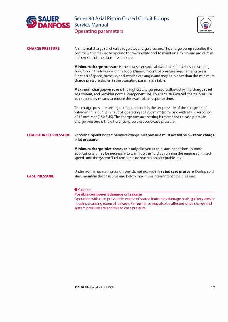
An internal charge relief valve regulates charge pressure. The charge pump supplies the
control with pressure to operate the swashplate and to maintain a minimum pressure in
the low side of the transmission loop.
m chr prr is the lowest pressure allowed to maintain a safe working
condition in the low side of the loop. Minimum control pressure requirements are a
function of speed, pressure, and swashplate angle, and may be higher than the minimum
charge pressure shown in the operating parameters table.
mx chr prr is the highest charge pressure allowed by the charge relief
adjustment, and provides normal component life. You can use elevated charge pressure
as a secondary means to reduce the swashplate response time.
The charge pressure setting in the order code is the set pressure of the charge relief
valve with the pump in neutral, operating at 1800 min-1
(rpm), and with a uid viscosityof 32 mm2 /sec (150 SUS). The charge pressure setting is referenced to case pressure.
Charge pressure is the differential pressure above case pressure.
At normal operating temperature charge inlet pressure must not fall below rd chr
l prr.
m chr l prr is only allowed at cold start conditions. In some
applications it may be necessary to warm up the uid by running the engine at limited
speed until the system uid temperature reaches an acceptable level.
Under normal operating conditions, do not exceed the rd c prr. During cold
start, maintain the case pressure below maximum intermittent case pressure.
CCaution
Pl cp d r l
Operation with case pressure in excess of stated limits may damage seals, gaskets, and/or
housings, causing external leakage. Performance may also be affected since charge and
system pressure are additive to case pressure.
CHaRge inLet PRessuRe
CHaRge PRessuRe
7/28/2019 Sauer90-ServiceManual.pdf
http://slidepdf.com/reader/full/sauer90-servicemanualpdf 18/72
18 520L0818 • Rev AB • April 2008
Series 90 Axial Piston Closed Circuit Pumps
Service Manual
Operating parameters
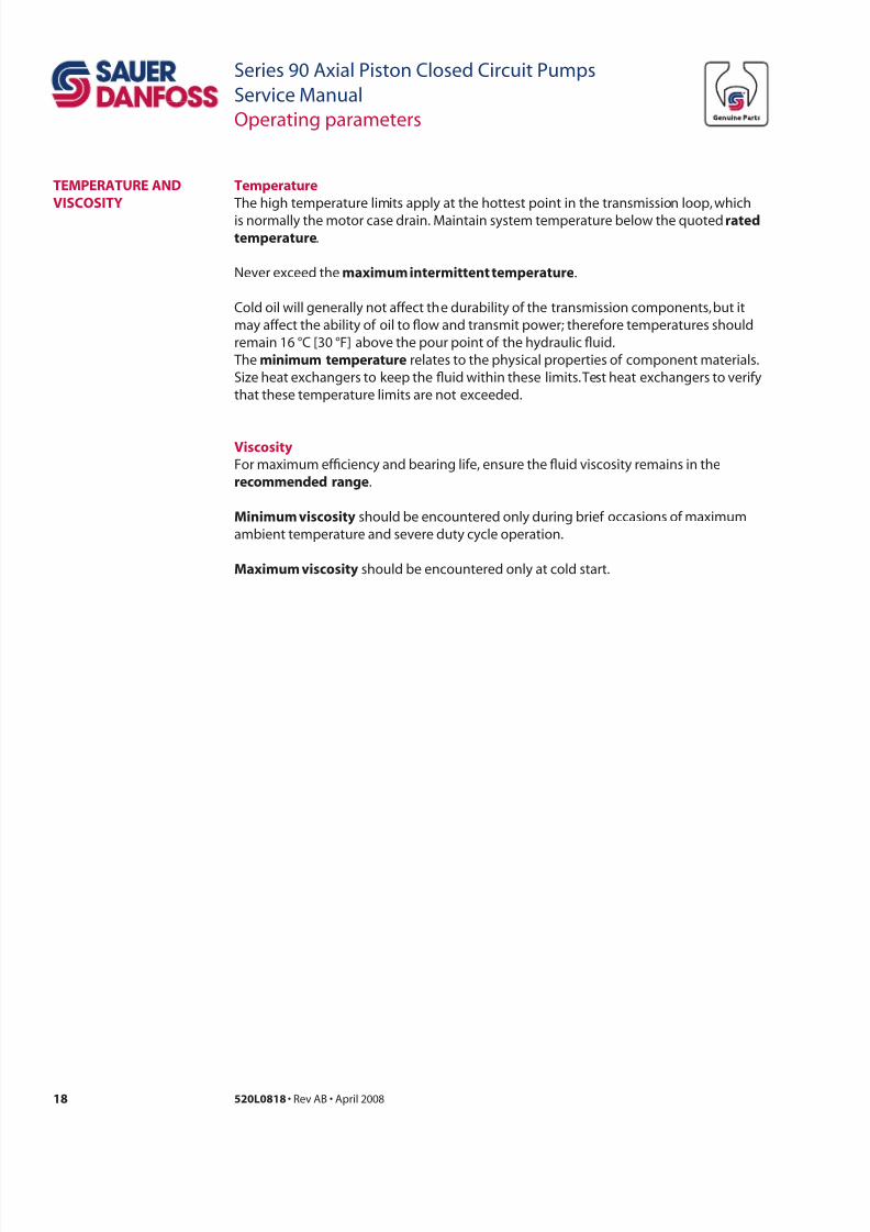
tprr
The high temperature limits apply at the hottest point in the transmission loop, which
is normally the motor case drain. Maintain system temperature below the quoted rdprr.
Never exceed the x r prr.
Cold oil will generally not affect the durability of the transmission components, but it
may affect the ability of oil to ow and transmit power; therefore temperatures should
remain 16 °C [30 °F] above the pour point of the hydraulic uid.
The prr relates to the physical properties of component materials.
Size heat exchangers to keep the uid within these limits. Test heat exchangers to verify
that these temperature limits are not exceeded.
vc
For maximum efciency and bearing life, ensure the uid viscosity remains in the
rcdd r.
m c should be encountered only during brief occasions of maximum
ambient temperature and severe duty cycle operation.
mx c should be encountered only at cold start.
temPeRatuRe anD
visCosity
7/28/2019 Sauer90-ServiceManual.pdf
http://slidepdf.com/reader/full/sauer90-servicemanualpdf 19/72
19520L0818 • Rev AB • April 2008
Series 90 Axial Piston Closed Circuit Pumps
Service Manual
Operating parameters
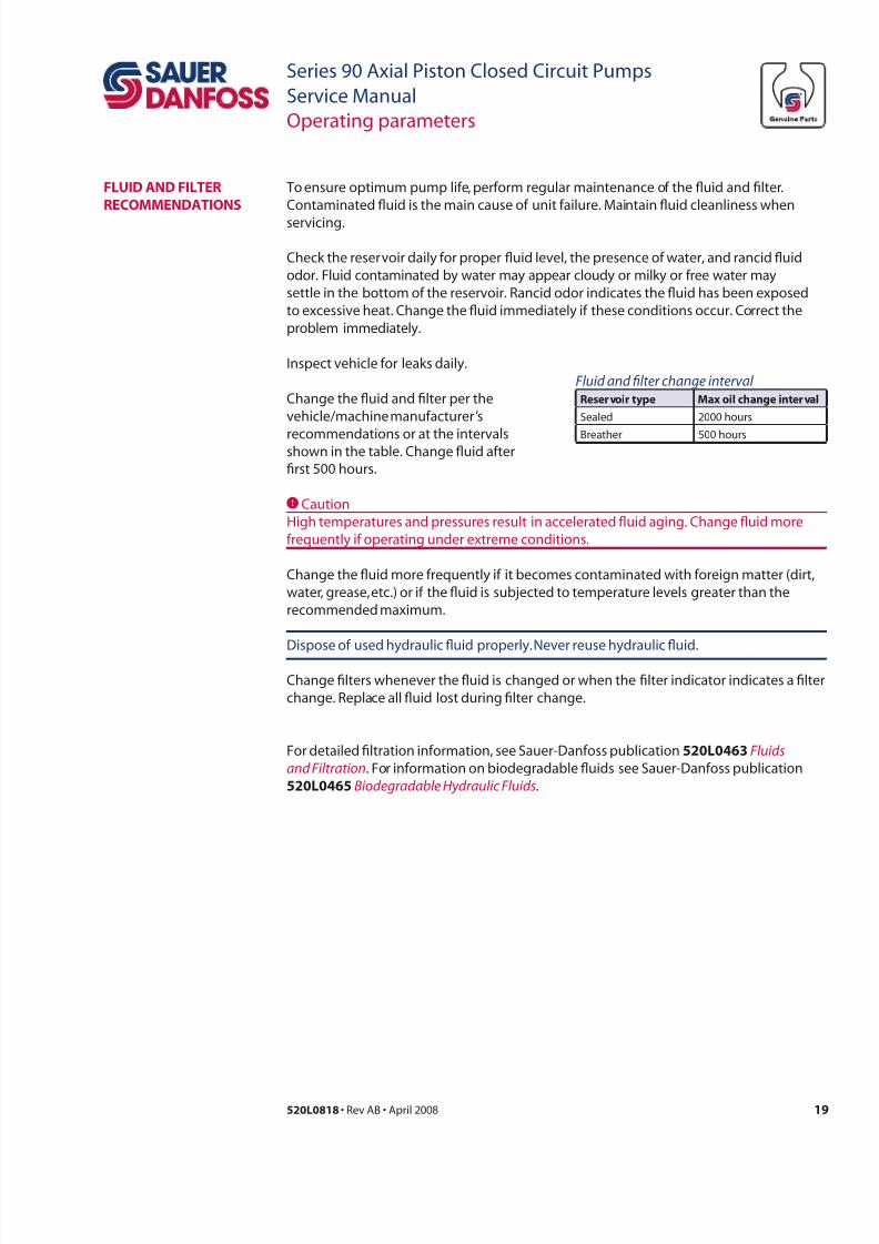
To ensure optimum pump life, perform regular maintenance of the uid and lter.
Contaminated uid is the main cause of unit failure. Maintain uid cleanliness when
servicing.
Check the reservoir daily for proper uid level, the presence of water, and rancid uid
odor. Fluid contaminated by water may appear cloudy or milky or free water may
settle in the bottom of the reservoir. Rancid odor indicates the uid has been exposed
to excessive heat. Change the uid immediately if these conditions occur. Correct the
problem immediately.
Inspect vehicle for leaks daily.
Change the uid and lter per the
vehicle/machine manufacturer’s
recommendations or at the intervalsshown in the table. Change uid after
rst 500 hours.
CCaution
High temperatures and pressures result in accelerated uid aging. Change uid more
frequently if operating under extreme conditions.
Change the uid more frequently if it becomes contaminated with foreign matter (dirt,
water, grease, etc.) or if the uid is subjected to temperature levels greater than the
recommended maximum.
Dispose of used hydraulic uid properly. Never reuse hydraulic uid.
Change lters whenever the uid is changed or when the lter indicator indicates a lter
change. Replace all uid lost during lter change.
LuiD anD iLteR
ReCommenDations
Fluid and flter change interval
Rrr p mx l ch rl
Sealed 2000 hours
Breather 500 hours
For detailed ltration information, see Sauer-Danfoss publication 520L0463 Fluids
and Filtration. For information on biodegradable uids see Sauer-Danfoss publication
520L0465 Biodegradable Hydraulic Fluids.
7/28/2019 Sauer90-ServiceManual.pdf
http://slidepdf.com/reader/full/sauer90-servicemanualpdf 20/72
20 520L0818 • Rev AB • April 2008
Series 90 Axial Piston Closed Circuit Pumps
Service Manual
Technical specications
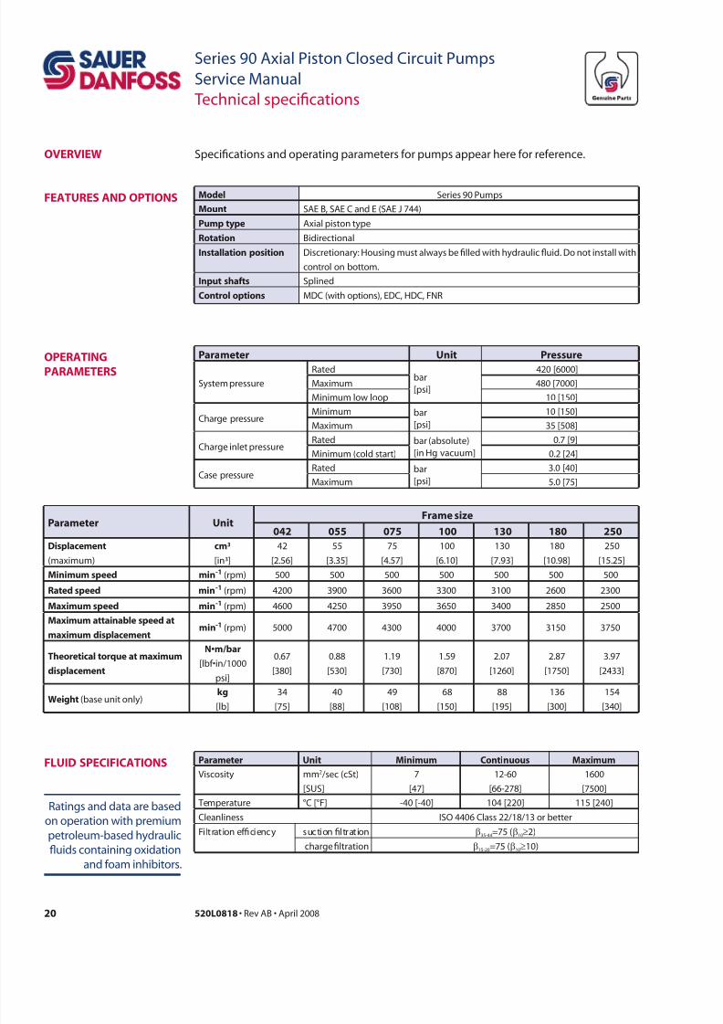
Prr ur
042 055 075 100 130 180 250
Dplc
(maximum)
c³
[in³]
42
[2.56]
55
[3.35]
75
[4.57]
100
[6.10]
130
[7.93]
180
[10.98]
250
[15.25]
m pd -1 (rpm) 500 500 500 500 500 500 500
Rd pd -1 (rpm) 4200 3900 3600 3300 3100 2600 2300
mx pd -1 (rpm) 4600 4250 3950 3650 3400 2850 2500
mx l pd
x dplc-1 (rpm) 5000 4700 4300 4000 3700 3150 3750
thrcl r x
dplc
N•m/bar
[lbf•in/1000
psi]
0.67
[380]
0.88
[530]
1.19
[730]
1.59
[870]
2.07
[1260]
2.87
[1750]
3.97
[2433]
wh (base unit only)
[lb]
34
[75]
40
[88]
49
[108]
68
[150]
88
[195]
136
[300]
154
[340]
oveRview
mdl Series 90 Pumps
m SAE B, SAE C and E (SAE J 744)
Pp p Axial piston type
R Bidirectional
ill p Discretionary: Housing must always be lled with hydraulic uid. Do not install with
control on bottom.
ip h Splined
Crl p MDC (with options), EDC, HDC, FNR
eatuRes anD oPtions
Specications and operating parameters for pumps appear here for reference.
Prr u m C mx
Viscosity mm2 /sec (cSt)
[SUS]
7
[47]
12-60
[66-278]
1600
[7500]
Temperature °C [°F] -40 [-40] 104 [220] 115 [240]
Cleanliness ISO 4406 Class 22/18/13 or better
Filtration efciency suction ltration β35-44=75 (β10≥2)
charge ltration β15-20=75 (β10≥10)
Ratings and data are based
on operation with premium
petroleum-based hydraulic
uids containing oxidation
and foam inhibitors.
LuiD sPeCiiCations
Prr u Prr
System pressure
Ratedbar
[psi]
420 [6000]
Maximum 480 [7000]
Minimum low loop 10 [150]
Charge pressureMinimum bar
[psi]
10 [150]
Maximum 35 [508]
Charge inlet pressureRated bar (absolute)
[in Hg vacuum]
0.7 [9]
Minimum (cold start) 0.2 [24]
Case pressureRated bar
[psi]
3.0 [40]
Maximum 5.0 [75]
oPeRatingPaRameteRs
7/28/2019 Sauer90-ServiceManual.pdf
http://slidepdf.com/reader/full/sauer90-servicemanualpdf 21/72
21520L0818 • Rev AB • April 2008
Series 90 Axial Piston Closed Circuit Pumps
Service Manual
Initial start-up procedure
Follow this procedure when starting-up a new pump installation or when restarting an
installation in which the pump was removed.
W Warning
Unintended movement of the machine or mechanism may cause injury to the technician
or bystanders. To protect against unintended movement, secure the machine or disable/
disconnect the mechanism while servicing.
Prior to installing the pump, inspect for shipping damage.
1. Ensure that the hydraulic uid and system components (reservoir, hoses, valves,
ttings, and heat exchanger) are clean and free of contamination.
2. Install new system lter element(s) if necessary. Check that inlet line ttings are
properly tightened and there are no air leaks.
3. Install the pump. Install a 50 bar [1000 psi] gauge in the charge pressure gauge port
M3.
4. Fill the housing by adding ltered uid in the upper case drain port. Open the case
plug in the top of the control to assist with air bleed.
5. Fill the reservoir with hydraulic uid of the recommended type and viscosity. Use a
10-micron ller lter. Fill inlet line from reservoir to pump.
6. Disconnect the pump control input signal.
After start-up the uid level in the reservoir may drop due to lling of the system
components. Check the level in the reservoir to maintain a full uid level throughout the
start-up procedure.
C Caution
Damage to hydraulic components may occur from failure to maintain uid supply.
7. Use a common method to disable the engine to prevent the engine from starting.
Crank the starter for several seconds. Do not to exceed the engine manufacturer’s
recommendation. Wait 30 seconds and then crank the engine a second time.
This operation helps remove air from the system lines. Rell the reservoir to
recommended full uid level.
geneRaL
staRt-uP PRoCeDuRe
7/28/2019 Sauer90-ServiceManual.pdf
http://slidepdf.com/reader/full/sauer90-servicemanualpdf 22/72
22 520L0818 • Rev AB • April 2008
Series 90 Axial Piston Closed Circuit Pumps
Service Manual
Initial start-up procedure
8. When charge pressure reaches 3.5 bar [50 psi], enable and start engine. Let the
engine run for a minimum of 30 seconds at low idle to allow the air to work itself out
of the system. Check for leaks at all line connections and listen for cavitation. Check for proper uid level in reservoir.
CCaution
Air entrapment in uid under high pressure may damage hydraulic components.
CCaution
Do not run at maximum pressure until system is free of air and uid has been thoroughly
ltered.
9. When adequate charge pressure is established (as shown in model code), increase
engine speed to normal operating rpm to further purge residual air from the system.
10. Shut off the engine. Connect the pump control signal. Start the engine, checking to
be certain the pump remains in neutral. Run the engine at normal operating speed
and carefully check for forward and reverse control operation.
11. Continue to cycle between forward and reverse for at least ve minutes to bleed all
air and ush system contaminants out of loop.
Normal charge pressure uctuation may occur during forward and reverse operation.
12. Check that the reservoir is full. Remove charge pressure gauge. The pump is now
ready for operation.
staRt-uP PRoCeDuRe
(cd)
7/28/2019 Sauer90-ServiceManual.pdf
http://slidepdf.com/reader/full/sauer90-servicemanualpdf 23/72
23520L0818 • Rev AB • April 2008
Series 90 Axial Piston Closed Circuit Pumps
Service Manual
Pressure measurement
RequiReD tooLs You can perform the service procedures described in this manual using common
mechanic’s tools. Special tools, if required are shown. Use calibrated pressure gauges to
ensure accuracy. Use snubbers to protect pressure gauges.
PoRt LoCations anD
gauge instaLLation
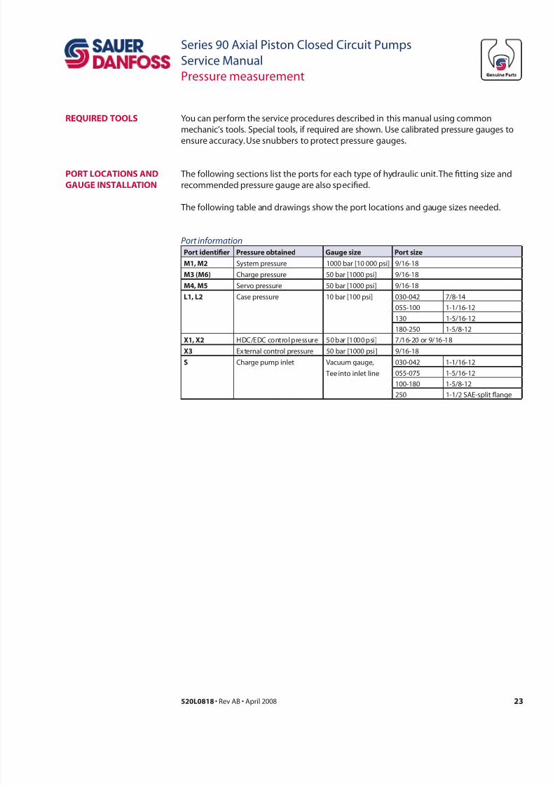
The following sections list the ports for each type of hydraulic unit. The tting size and
recommended pressure gauge are also specied.
The following table and drawings show the port locations and gauge sizes needed.
Port inormation
Pr dfr Prr d g Pr
m1, m2 System pressure 1000 bar [10 000 psi] 9/16-18
m3 (m6) Charge pressure 50 bar [1000 psi] 9/16-18m4, m5 Servo pressure 50 bar [1000 psi] 9/16-18
L1, L2 Case pressure 10 bar [100 psi] 030-042 7/8-14
055-100 1-1/16-12
130 1-5/16-12
180-250 1-5/8-12
X1, X2 HDC/EDC control pressure 50 bar [1000 psi] 7/16-20 or 9/16-18
X3 External control pressure 50 bar [1000 psi] 9/16-18
s Charge pump inlet Vacuum gauge,
Tee into inlet line
030-042 1-1/16-12
055-075 1-5/16-12
100-180 1-5/8-12
250 1-1/2 SAE-split ange
7/28/2019 Sauer90-ServiceManual.pdf
http://slidepdf.com/reader/full/sauer90-servicemanualpdf 24/72
24 520L0818 • Rev AB • April 2008
Series 90 Axial Piston Closed Circuit Pumps
Service Manual
Pressure measurement
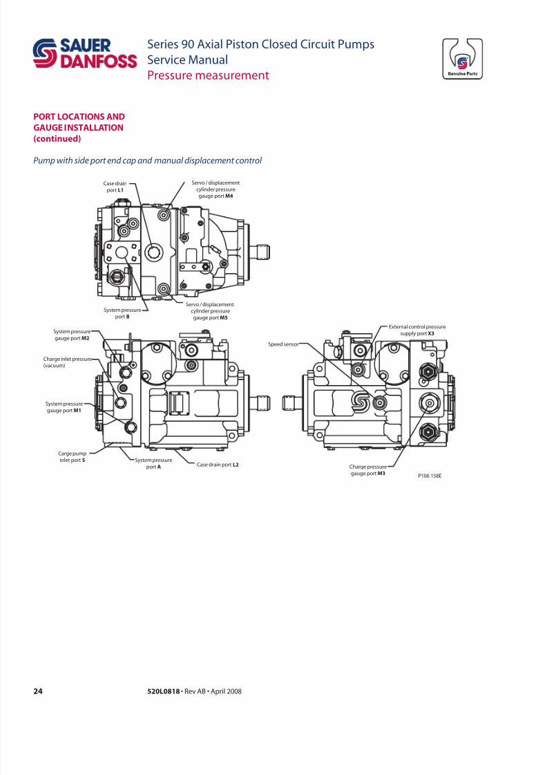
Pump with side port end cap and manual displacement control
Servo / displacement
cylinder pressure
gauge portM5
Servo / displacement
cylinder pressure
gauge portM4
Case drain
port L1
System pressure
port B
External control pressure
supply port X3
Charge pressure
gauge portM3
Speed sensor
P106 158E
System pressure
gauge port M2
System pressure
gauge portM1
System pressure
port A Case drain port L2
Carge pump
inlet port S
Charge inlet pressure
(vacuum)
PoRt LoCations anD
gauge instaLLation
(cd)
7/28/2019 Sauer90-ServiceManual.pdf
http://slidepdf.com/reader/full/sauer90-servicemanualpdf 25/72
25520L0818 • Rev AB • April 2008
Series 90 Axial Piston Closed Circuit Pumps
Service Manual
Pressure measurement
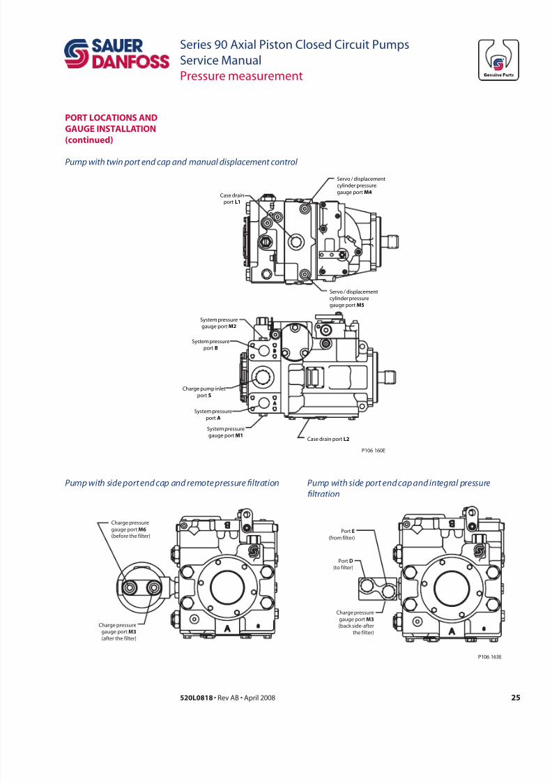
Pump with twin port end cap and manual displacement control
Pump with side port end cap and remote pressure fltration Pump with side port end cap and integral pressure
fltration
Servo / displacement
cylinder pressure
gauge port M5
Servo / displacement
cylinder pressure
gauge port M4Case drain
port L1
System pressure
gauge portM2
System pressure
gauge portM1Case drain port L2
System pressure
port B
Charge pump inlet
port S
System pressureport A
P106 160E
Charge pressure
gauge portM3
(after the filter)
Charge pressure
gauge portM6
(before the filter)
Charge pressure
gauge portM3
(back side-after
the filter)
Port E
(from filter)
PortD
(to filter)
P106 163E
PoRt LoCations anD
gauge instaLLation
(cd)
7/28/2019 Sauer90-ServiceManual.pdf
http://slidepdf.com/reader/full/sauer90-servicemanualpdf 26/72
26 520L0818 • Rev AB • April 2008
Series 90 Axial Piston Closed Circuit Pumps
Service Manual
Troubleshooting
This section provides general steps to follow if certain undesirable system conditions
occur. Follow the steps in a section until you solve the problem. Some of the items
are system specic. For areas covered in this manual, we reference the section. Alwaysobserve the safety precautions listed in the Introduction section (page 6) and those
relating to your specic equipment.
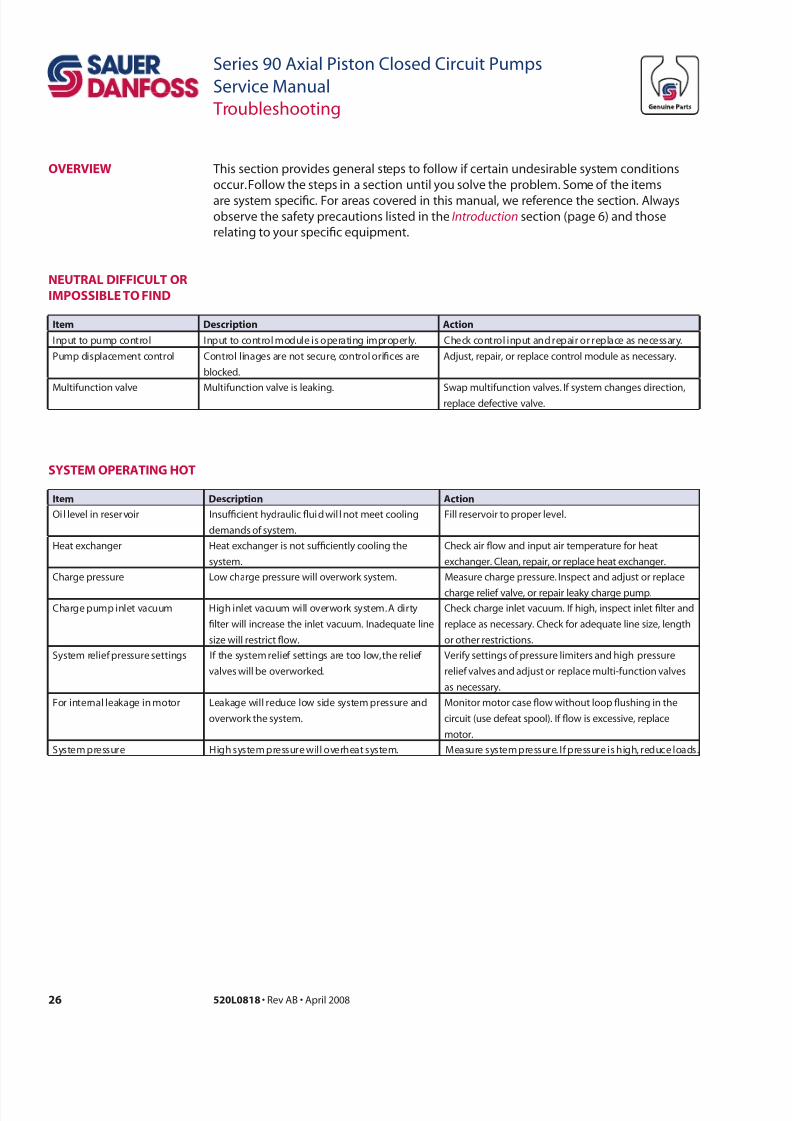
oveRview
i Dcrp ac
Input to pump control Input to control module is operating improperly. Check control input and repair or replace as necessary.
Pump displacement control Control linages are not secure, control orices are
blocked.
Adjust, repair, or replace control module as necessary.
Multifunction valve Multifunction valve is leaking. Swap multifunction valves. If system changes direction,replace defective valve.
i Dcrp ac
Oil level in reservoir Insufcient hydraulic uid wil l not meet cooling
demands of system.
Fill reservoir to proper level.
Heat exchanger Heat exchanger is not sufciently cooling the
system.
Check air ow and input air temperature for heat
exchanger. Clean, repair, or replace heat exchanger.
Charge pressure Low charge pressure will overwork system. Measure charge pressure. Inspect and adjust or replace
charge relief valve, or repair leaky charge pump.
Charge pump inlet vacuum High inlet vacuum will overwork system. A dirty
lter will increase the inlet vacuum. Inadequate line
size will restrict ow.
Check charge inlet vacuum. If high, inspect inlet lter and
replace as necessary. Check for adequate line size, length
or other restrictions.
System relief pressure settings If the system relief settings are too low, the relief
valves will be overworked.
Verify settings of pressure limiters and high pressure
relief valves and adjust or replace multi-function valves
as necessary.
For internal leakage in motor Leakage will reduce low side system pressure and
overwork the system.
Monitor motor case ow without loop ushing in the
circuit (use defeat spool). If ow is excessive, replace
motor.
System pressure High system pressure will overheat system. Measure system pressure. If pressure is high, reduce loads.
neutRaL DiiCuLt oR
imPossibLe to inD
system oPeRating Hot
7/28/2019 Sauer90-ServiceManual.pdf
http://slidepdf.com/reader/full/sauer90-servicemanualpdf 27/72
27520L0818 • Rev AB • April 2008
Series 90 Axial Piston Closed Circuit Pumps
Service Manual
Troubleshooting
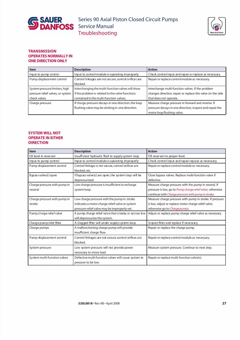
i Dcrp ac
Input to pump control Input to control module is operating improperly. Check control input and repair or replace as necessary.
Pump displacement control Control linkages are not secure, control orices are
blocked.
Repair or replace control module as necessary.
System pressure limiters, high
pressure relief valves, or system
check valves
Interchanging the multi-function valves will show
if the problem is related to the valve functions
contained in the multi-function valves.
Interchange multi-function valves. If the problem
changes direction, repair or replace the valve on the side
that does not operate.
Charge pressure If charge pressure decays in one direction, the loop
ushing valve may be sticking in one direction.
Measure charge pressure in forward and reverse. If
pressure decays in one direction, inspect and repair the
motor loop ushing valve.
i Dcrp ac
Oil level in reservoir Insufcient hydraul ic uid to supply system loop Fill reservoir to proper level.
Input to pump control Input to control module is operating improperly Check control input and repair replace as necessary.
Pump displacement control Control linkage is not secure, control orices are
blocked, etc.
Repair or replace control module as necessary.
Bypass valve(s) open If bypass valve(s) are open, the system loop will be
depressurized.
Close bypass valves. Replace multi-function valve if
defective.
Charge pressure with pump in
neutral
Low charge pressure is insufcient to recharge
system loop.
Measure charge pressure with the pump in neutral. If
pressure is low, go to Pump charge relie valve; otherwise
continue with Charge pressure with pump in stroke.
Charge pressure with pump in
stroke
Low charge pressure with the pump in stroke
indicates a motor charge relief valve or system
pressure relief valve may be improperly set.
Measure charge pressure with pump in stroke. If pressure
is low, adjust or replace motor charge relief valve,
otherwise go to Charge pumps.
Pump charge relief valve A pump charge relief valve that is leaky or set too low
will depressurize the system.
Adjust or replace pump charge relief valve as necessary.
Charge pump inlet lter A clogged lter will under supply system loop. Inspect lter and replace if necessary.
Charge pumps A malfunctioning charge pump will provide
insufcient charge ow.
Repair or replace the charge pump.
Pump displacement control Control linkages are not secure, control orices areblocked.
Repair or replace control module as necessary.
System pressure Low system pressure will not provide power
necessary to move load.
Measure system pressure. Continue to next step.
System multi-function valves Defective multi-function valves will cause system to
pressure to be low.
Repair or replace multi-function valve(s).
tRansmission
oPeRates noRmaLLy in
one DiReCtion onLy
system wiLL not
oPeRate in eitHeR
DiReCtion

7/28/2019 Sauer90-ServiceManual.pdf
http://slidepdf.com/reader/full/sauer90-servicemanualpdf 28/72
28 520L0818 • Rev AB • April 2008
Series 90 Axial Piston Closed Circuit Pumps
Service Manual
Troubleshooting
i Dcrp ac
System pressure at motor Low system pressure at the motor will reduce torque Measure system pressure at motor. If pressure limiter
setting is low, increase setting.
Variable motor stuck at
minimum displacement
Minimum motor displacement yields low output
torque.
Check control supply pressure or repair displacement
control. Check motor control orices.
Internal leakage Internal leakage will reduce system pressure. Check for leaking O-rings, gaskets and other ttings.
Repair unit as required, or replace leaking unit.
i Dcrp ac
Oil level in reservoir Insufcient hydraulic uid will reduce motor speed. Fill oil to proper level.
Pump output ow Incorrect outow wil l affect output speed. Incorrect
output ow indicates the swashplate is out of
position.
Measure pump output and check for proper pump speed.
Ensure the pump is in full stroke.
Variable motor displacement
control
If variable motor displacement control is not
functioning correctly, variable motor swashplate may
be in wrong position.
See if variable motor displacement control is responding.
If not, repair or replace control.
Internal leakage Internal leakage will reduce system pressure. Check for leaking O-rings, gaskets, and other ttings.
Repair unit as required, or replace leaky unit.
Low motoR outPut
toRque
imPRoPeR motoR
outPut sPeeD
i Dcrp ac
Oil in reser voir Insufcient hydraulic uid will lead to cavitation. Fill reservoir to proper level.
Air in system Air bubbles will lead to cavitation. Look for foam in reservoir. Check for leaks on inlet side
system loop and repair. Afterwards, let reservoir settle
until foam dissipates. Run system at low speed to move
system uid to reservoir. Repeat.
Pump inlet vacuum High inlet vacuum causes noise. A dirty lter will
increase the inlet vacuum.
Inspect and replace lter as necessary. Check for proper
suction line size.
Shaft couplings A loose shaft coupling will cause excessive noise. Replace loose shaft coupling or replace pump or motor.
Shaft alignment Misaligned shafts cause noise. Align shafts.
system noise oR
vibRation
7/28/2019 Sauer90-ServiceManual.pdf
http://slidepdf.com/reader/full/sauer90-servicemanualpdf 29/72
29520L0818 • Rev AB • April 2008
Series 90 Axial Piston Closed Circuit Pumps
Service Manual
Troubleshooting
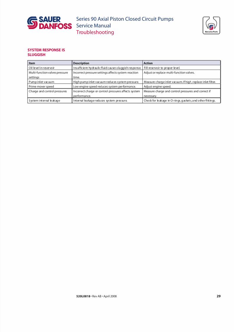
i Dcrp ac
Oil level in reservoir Insufcient hydraulic uid causes sluggish response. Fill reservoir to proper level.
Multi-function valves pressure
settings
Incorrect pressure settings affects system reaction
time.
Adjust or replace multi-function valves.
Pump inlet vacuum High pump inlet vacuum reduces system pressure. Measure charge inlet vacuum. If high, replace inlet lter.
Prime mover speed Low engine speed reduces system per formance. Adjust engine speed.
Charge and control pressures Incorrect charge or control pressures affects system
performance.
Measure charge and control pressures and correct if
necessary.
System internal leakage Internal leakage reduces system pressure. Check for leakage in O-rings, gaskets, and other ttings.
system ResPonse is
sLuggisH
7/28/2019 Sauer90-ServiceManual.pdf
http://slidepdf.com/reader/full/sauer90-servicemanualpdf 30/72
30 520L0818 • Rev AB • April 2008
Series 90 Axial Piston Closed Circuit Pumps
Service Manual
Adjustments
stanDaRD
PRoCeDuRes,
insPeCtions, anDaDjustments
Before working on the pump, clean the outside of the pump.
CC
Contamination can damage internal components and void your warranty. Take
precautions to ensure system cleanliness when removing and reinstalling system lines.
1. With the prime mover off, thoroughly clean the outside of the pump.
2. If removing the pump, tag each hydraulic line connected to the pump. If hydraulic
lines are disconnected, plug each open port with a clean plug, to ensure that dirt and
contamination do not get into the pump.
3. Ensure the surrounding areas are clean and free of contaminants.
4. Inspect the system for contamination.
5. Visually inspect the hydraulic uid for signs of system contamination, uid
discoloration, foam in the uid, sludge, or small metal particles.
6. If there are signs of contamination in the hydraulic uid, replace all lters, drain and
ush the hydraulic system, and ll with the correct ltered hydraulic uid.
7. Flush the lines before replacing the hydraulic uid.
7/28/2019 Sauer90-ServiceManual.pdf
http://slidepdf.com/reader/full/sauer90-servicemanualpdf 31/72
31520L0818 • Rev AB • April 2008
Series 90 Axial Piston Closed Circuit Pumps
Service Manual
Adjustments
aDjustments This section offers instruction on inspection and adjustment of pump components. Read
through the entire related section before beginning a service activity. Refer to Pressure
measurements, pages 23, 24 and 25, for location of gauge ports and suggested gaugesizes.
CHaRge PRessuRe
ReLie vaLve
aDjustment
The following procedure explains how to check and adjust the charge pressure relief
valve.
Wwr
The following procedure
may require the vehicle/
machine to be disabled
(wheels raised off the
ground, work functiondisconnected, etc.) in order
to prevent injury to the
technician and bystanders.
Take necessary safety
precautions before moving
the vehicle/machine.
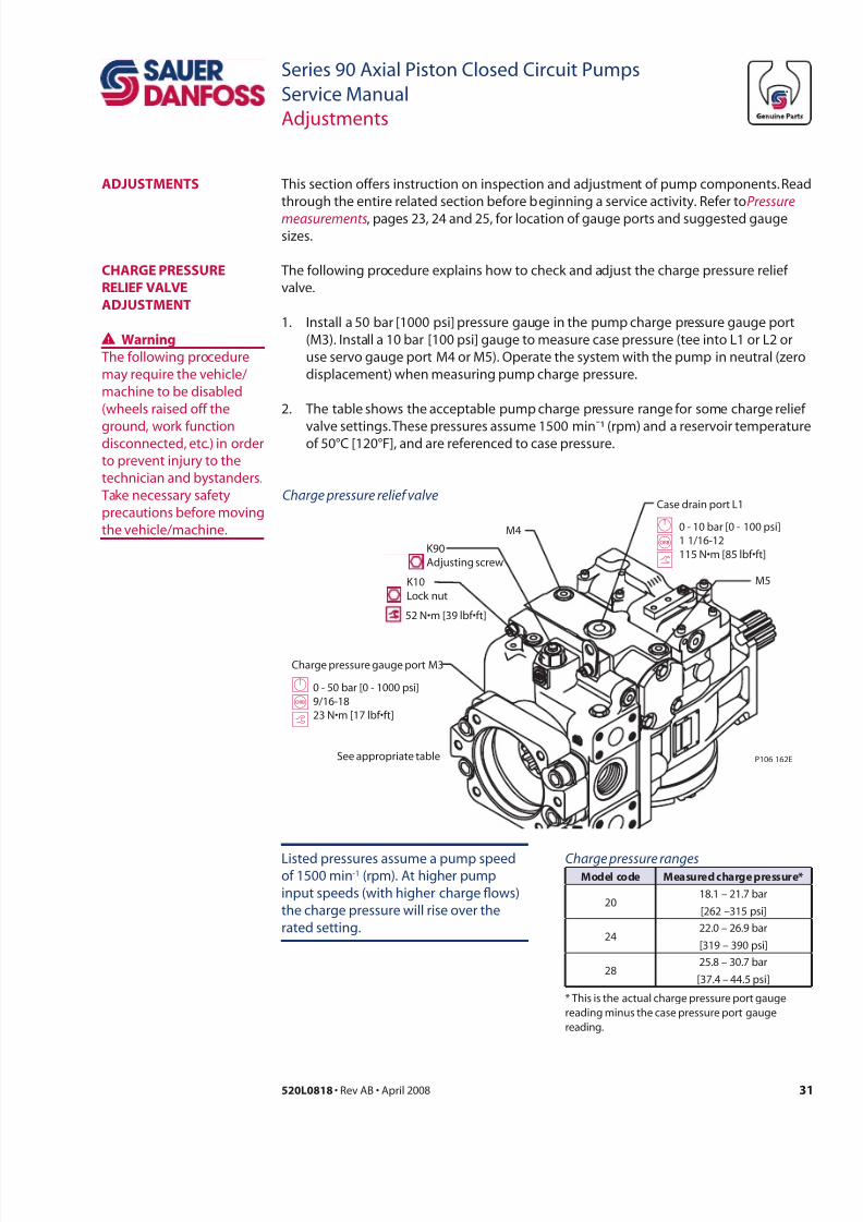
Listed pressures assume a pump speedof 1500 min-1 (rpm). At higher pump
input speeds (with higher charge ows)
the charge pressure will rise over the
rated setting.
Charge pressure rangesmdl cd mrd chr prr*
2018.1 – 21.7 bar
[262 –315 psi]
2422.0 – 26.9 bar
[319 – 390 psi]
2825.8 – 30.7 bar
[37.4 – 44.5 psi]
* This is the actual charge pressure port gauge
reading minus the case pressure port gauge
reading.
Charge pressure gauge port M3
K90
Adjusting screw
K10
Lock nut
Case drain port L1
52 N•m [39 lbf•ft]
GBt
GBt
0 - 10 bar [0 - 100 psi]1 1/16-12
115 N•m [85 lbf•ft]
0 - 50 bar [0 - 1000 psi]
9/16-1823 N•m [17 lbf•ft]
P106 162ESee appropriate table
M4
M5
Charge pressure relie valve
1. Install a 50 bar [1000 psi] pressure gauge in the pump charge pressure gauge port
(M3). Install a 10 bar [100 psi] gauge to measure case pressure (tee into L1 or L2 or
use servo gauge port M4 or M5). Operate the system with the pump in neutral (zero
displacement) when measuring pump charge pressure.
2. The table shows the acceptable pump charge pressure range for some charge relief
valve settings. These pressures assume 1500 min¯¹ (rpm) and a reservoir temperatureof 50°C [120°F], and are referenced to case pressure.
7/28/2019 Sauer90-ServiceManual.pdf
http://slidepdf.com/reader/full/sauer90-servicemanualpdf 32/72
32 520L0818 • Rev AB • April 2008
Series 90 Axial Piston Closed Circuit Pumps
Service Manual
Adjustments
3. Earlier production Series 90 pumps have a shim adjustable charge pressure relief
valve. Shim kits are available from Sauer-Danfoss. Remove the plug using a 1in hex
wrench and exchange shims behind the spring to adjust charge pressure. Torqueplug to 68 N•m [50 lbf•ft].
4. Later production Series 90 pumps have an external screw-adjustable charge
pressure relief valve. Loosen locknut (K10) and turn the adjusting screw (K90) using a
screwdriver or 1/2 in. hex wrench to adjust charge pressure setting.
Lock nut wrench size
r wrch
030 – 100 1-1/16 inch
130 – 250 1-5/8 inch
5. Clockwise rotation of the plug increases the setting and counterclockwise rotation
decreases the setting (at a rate of approximately 3.9 bar [50 psi] per turn). Torque
lock nut to 52 N•m [39 lbf•ft].
6. Once you achieve the desired charge pressure setting, remove the gauges and plug
the ports.
CHaRge PRessuRe
ReLie vaLve
aDjustment(cd)
7/28/2019 Sauer90-ServiceManual.pdf
http://slidepdf.com/reader/full/sauer90-servicemanualpdf 33/72
33520L0818 • Rev AB • April 2008
Series 90 Axial Piston Closed Circuit Pumps
Service Manual
Adjustments
muLti-unCtion vaLve
PRessuRe aDjustment
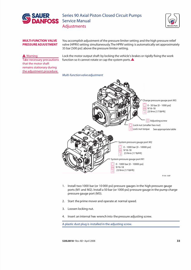
You accomplish adjustment of the pressure limiter setting and the high pressure relief
valve (HPRV) setting simultaneously. The HPRV setting is automatically set approximately
35 bar [500 psi] above the pressure limiter setting.
Lock the motor output shaft by locking the vehicle’s brakes or rigidly xing the work
function so it cannot rotate or cap the system ports.WWWarning
Take necessary precautions
that the motor shaft
remains stationary during
the adjustment procedure.
1. Install two 1000 bar (or 10 000 psi) pressure gauges in the high pressure gauge
ports (M1 and M2). Install a 50 bar (or 1000 psi) pressure gauge in the pump chargepressure gauge port (M3).
2. Start the prime mover and operate at normal speed.
3. Loosen locking nut.
4. Insert an internal hex wrench into the pressure adjusting screw.
A plastic dust plug is installed in the adjusting screw.
Charge pressure gauge port M3
System pressure gauge port M2
GBt
GBt
0 - 1000 bar [0 - 10000 psi]9/16-18
23 N•m [17 lbf•ft]
0 - 50 bar [0 - 1000 psi]9/16-18
23 N•m [17 lbf•ft]
P106 168E
See appropriate table
System pressure gauge port M1
GBt
0 - 1000 bar [0 - 10000 psi]9/16-18
23 N•m [17 lbf•ft]
Adjusting screw
Lock nut (smaller hex nut)
Lock nut torqueth
I
Multi-unction valve adjustment
7/28/2019 Sauer90-ServiceManual.pdf
http://slidepdf.com/reader/full/sauer90-servicemanualpdf 34/72
34 520L0818 • Rev AB • April 2008
Series 90 Axial Piston Closed Circuit Pumps
Service Manual
Adjustments
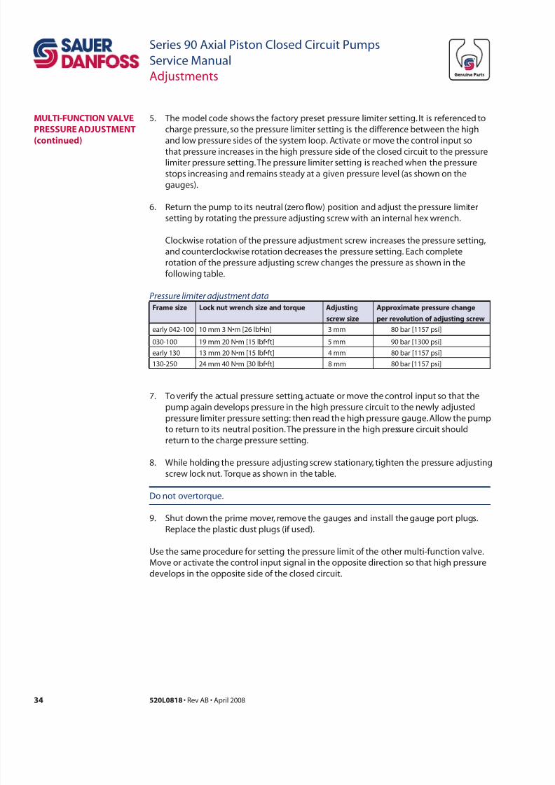
5. The model code shows the factory preset pressure limiter setting. It is referenced to
charge pressure, so the pressure limiter setting is the difference between the high
and low pressure sides of the system loop. Activate or move the control input sothat pressure increases in the high pressure side of the closed circuit to the pressure
limiter pressure setting. The pressure limiter setting is reached when the pressure
stops increasing and remains steady at a given pressure level (as shown on the
gauges).
6. Return the pump to its neutral (zero ow) position and adjust the pressure limiter
setting by rotating the pressure adjusting screw with an internal hex wrench.
Clockwise rotation of the pressure adjustment screw increases the pressure setting,
and counterclockwise rotation decreases the pressure setting. Each complete
rotation of the pressure adjusting screw changes the pressure as shown in the
following table.
7. To verify the actual pressure setting, actuate or move the control input so that the
pump again develops pressure in the high pressure circuit to the newly adjusted
pressure limiter pressure setting: then read the high pressure gauge. Allow the pump
to return to its neutral position. The pressure in the high pressure circuit should
return to the charge pressure setting.
8. While holding the pressure adjusting screw stationary, tighten the pres sure adjusting
screw lock nut. Torque as shown in the table.
Do not overtorque.
9. Shut down the prime mover, remove the gauges and install the gauge port plugs.
Replace the plastic dust plugs (if used).
Use the same procedure for setting the pressure limit of the other multi-function valve.Move or activate the control input signal in the opposite direction so that high pressure
develops in the opposite side of the closed circuit.
Pressure limiter adjustment data
r Lc rch d r ad
cr
apprx prr ch
pr rl d cr
early 042-100 10 mm 3 N•m [26 lbf•in] 3 mm 80 bar [1157 psi]
030-100 19 mm 20 N•m [15 lbf•ft] 5 mm 90 bar [1300 psi]
early 130 13 mm 20 N•m [15 lbf•ft] 4 mm 80 bar [1157 psi]
130-250 24 mm 40 N•m [30 lbf•ft] 8 mm 80 bar [1157 psi]
muLti-unCtion vaLve
PRessuRe aDjustment
(cd)
7/28/2019 Sauer90-ServiceManual.pdf
http://slidepdf.com/reader/full/sauer90-servicemanualpdf 35/72
35520L0818 • Rev AB • April 2008
Series 90 Axial Piston Closed Circuit Pumps
Service Manual
Adjustments
engaging tHe byPass
unCtion
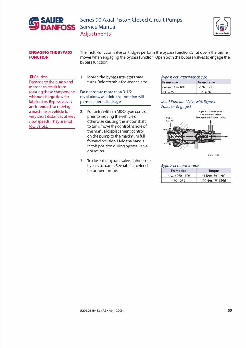
The multi-function valve cartridges perform the bypass function. Shut down the prime
mover when engaging the bypass function. Open both the bypass valves to engage the
bypass function.
Bypass actuator wrench size
r wrch
newer 030 – 100 1-1/16 inch
130 – 250 1-3/8 inch
1. loosen the bypass actuator three
turns. Refer to table for wrench size.
Do not rotate more than 3-1/2
revolutions, as additional rotation will
permit external leakage.
2. For units with an MDC-type control,
prior to moving the vehicle or
otherwise causing the motor shaftto turn, move the control handle of
the manual displacement control
on the pump to the maximum full
forward position. Hold the handle
in this position during bypass valve
operation.
3. To close the bypass valve, tighten the
bypass actuator. See table provided
for proper torque.
CCaution
Damage to the pump and
motor can result from
rotating these components
without charge ow for
lubrication. Bypass valves
are intended for moving
a machine or vehicle for
very short distances at very
slow speeds. They are nottow valves.
Multi-Function Valve with Bypass
Function Engaged
Bypass
actuator
Opening bypass valve
allows flow to circuit
through multi-function valves
P104 144E
Bypass actuator torque
r tr
newer 030 – 100 41 N•m [30 lbf•ft]
130 – 250 100 N•m [75 lbf•ft]
7/28/2019 Sauer90-ServiceManual.pdf
http://slidepdf.com/reader/full/sauer90-servicemanualpdf 36/72
36 520L0818 • Rev AB • April 2008
Series 90 Axial Piston Closed Circuit Pumps
Service Manual
Adjustments
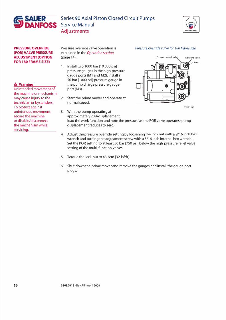
1. Install two 1000 bar [10 000 psi]
pressure gauges in the high pressure
gauge ports (M1 and M2). Install a
50 bar [1000 psi] pressure gauge in
the pump charge pressure gauge
port (M3).
2. Start the prime mover and operate at
normal speed.
3. With the pump operating atapproximately 20% displacement,
PRessuRe oveRRiDe
(PoR) vaLve PRessuRe
aDjustment (oPtionoR 180 Rame size)
Pressure override valve operation is
explained in the Operation section
(page 14).
Pressure override valve or 180 rame size
Pressure override valve
Lock nut
Adjusting screw
P104 145E
load the work function and note the pressure as the POR valve operates (pump
displacement reduces to zero).
4. Adjust the pressure override setting by loosening the lock nut with a 9/16 inch hex
wrench and turning the adjustment screw with a 3/16 inch internal hex wrench.
Set the POR setting to at least 50 bar [750 psi] below the high pressure relief valve
setting of the multi-function valves.
5. Torque the lock nut to 43 N•m [32 lbf•ft].
6. Shut down the prime mover and remove the gauges and install the gauge port
plugs.
Wwr
Unintended movement of
the machine or mechanism
may cause injury to the
technician or bystanders.
To protect against
unintended movement,secure the machine
or disable/disconnect
the mechanism while
servicing.
7/28/2019 Sauer90-ServiceManual.pdf
http://slidepdf.com/reader/full/sauer90-servicemanualpdf 37/72
37520L0818 • Rev AB • April 2008
Series 90 Axial Piston Closed Circuit Pumps
Service Manual
Adjustments
CCaution
Take care in adjusting
displacement limiters to
avoid undesirable ow or
speed conditions. Re-
torque lock nut (F212)
after every adjustment to
prevent an unexpectedchange in operating
conditions and to prevent
external leakage during
unit operation.
DisPLaCement LimiteR
aDjustment
You can limit the maximum displacement in either direction.
1. Loosen the lock nut (F212) whileholding the adjusting screw (F213)
steady.
2. Rotate the adjusting screw some
amount (using information in the
following table).CRotating the
adjusting screw clockwise decreases
the maximum displacement of the
pump while rotating the adjusting
screw counterclockwise increases
the maximum displacement.
3 One turn of the adjusting screw
changes the maximum displacement
as shown in table below
3. After establishing the desired
maximum displacement setting,
torque the lock nut to the torque
shown in table below.
r Lc rch d r ad
cr
apprx dplc ch
pr rl d cr
030 13 mm 24 N•m [18 lbf•ft] 4 mm 2.8 cm³/(rev) [0.17 in³/rev]
042 13 mm 24 N•m [18 lbf•ft] 4 mm 3.5 cm³/(rev) [0.21 in³/rev]
055 13 mm 24 N•m [18 lbf•ft] 4 mm 4.2 cm³/rev [0.26 in³/rev]
075 13 mm 24 N•m [18 lbf•ft] 4 mm 5.1 cm³/rev [0.31 in³/rev]
100 13 mm 24 N•m [18 lbf•ft] 4 mm 6.2 cm³/rev [0.38 in³/rev]
130 17 mm 48 N•m [35 lbf•ft] 5 mm 8.8 cm³/rev [0.53 in³/rev]
180 19 mm 125 N•m [92 lbf•ft] 6 mm 12.5 cm³/rev [0.76 in³/rev]
250 19 mm 125 N•m [92 lbf•ft] 6 mm 17.3 cm³/rev [1.06 in³/rev]
IAdjusting screw
Lock nut
Lock nut torque
P106 164E
F212
F213
Displacement limiter adjustment
There are no adjustable elements in the manual displacement control. Centering springs
and washers on each end of the control spool hold it in its neutral position. Since thereis no centering spring on the control input shaft, the shaft automatically assumes the
appropriate position when the control is installed on the pump.
stanDaRD manuaL
DisPLaCementContRoL (mDC)
aDjustment
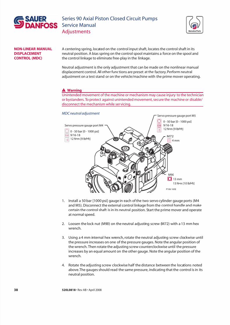
7/28/2019 Sauer90-ServiceManual.pdf
http://slidepdf.com/reader/full/sauer90-servicemanualpdf 38/72
38 520L0818 • Rev AB • April 2008
Series 90 Axial Piston Closed Circuit Pumps
Service Manual
Adjustments
A centering spring, located on the control input shaft, locates the control shaft in its
neutral position. A bias spring on the control spool maintains a force on the spool and
the control linkage to eliminate free-play in the linkage.
Neutral adjustment is the only adjustment that can be made on the nonlinear manual
displacement control. All other functions are preset at the factory. Perform neutral
adjustment on a test stand or on the vehicle/machine with the prime mover operating.
Wwr
Unintended movement of the machine or mechanism may cause injury to the technician
or bystanders. To protect against unintended movement, secure the machine or disable/
disconnect the mechanism while servicing.
1. Install a 50 bar [1000 psi] gauge in each of the two servo cylinder gauge ports (M4
and M5). Disconnect the external control linkage from the control handle and make
certain the control shaft is in its neutral position. Start the prime mover and operate
at normal speed.
2. Loosen the lock nut (M90) on the neutral adjusting screw (M72) with a 13 mm hex
wrench.
3. Using a 4 mm internal hex wrench, rotate the neutral adjusting screw clockwise until
the pressure increases on one of the pressure gauges. Note the angular position of
the wrench. Then rotate the adjusting screw counterclockwise until the pressure
increases by an equal amount on the other gauge. Note the angular position of the
wrench.
4. Rotate the adjusting screw clockwise half the distance between the locations noted
above. The gauges should read the same pressure, indicating that the control is in its
neutral position.
non-LineaR manuaL
DisPLaCement
ContRoL (mDC)
Servo pressure gauge port M4
Servo pressure gauge port M5
GBt
0 - 50 bar [0 - 1000 psi]
9/16-18
12 N•m [9 lbf•ft] 0 - 50 bar [0 - 1000 psi]
9/16-18
12 N•m [9 lbf•ft]
P106 165E
13 mm
13 N•m [10 lbf•ft]
I4 mm
M90
M72
MDC neutral adjustment
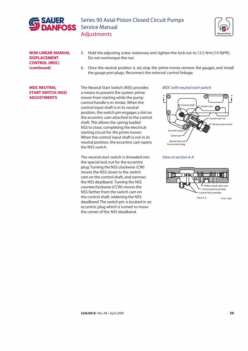
7/28/2019 Sauer90-ServiceManual.pdf
http://slidepdf.com/reader/full/sauer90-servicemanualpdf 39/72
39520L0818 • Rev AB • April 2008
Series 90 Axial Piston Closed Circuit Pumps
Service Manual
Adjustments
5. Hold the adjusting screw stationary and tighten the lock nut to 13.5 N•m [10 lbf•ft].
Do not overtorque the nut.
6. Once the neutral position is set, stop the prime mover, remove the gauges, and install
the gauge port plugs. Reconnect the external control linkage.
The Neutral Start Switch (NSS) provides
a means to prevent the system prime
mover from starting while the pump
control handle is in-stroke. When the
control input shaft is in its neutral
position, the switch pin engages a slot on
the eccentric cam attached to the control
shaft. This allows the spring loadedNSS to close, completing the electrical
starting circuit for the prime mover.
When the control input shaft is not in its
neutral position, the eccentric cam opens
the NSS switch.
The neutral start switch is threaded into
the special lock nut for the eccentric
plug. Turning the NSS clockwise (CW)
moves the NSS closer to the switch
cam on the control shaft, and narrows
the NSS deadband. Turning the NSS
counterclockwise (CCW) moves the
NSS farther from the switch cam on
the control shaft, widening the NSS
deadband. The switch pin is located in an
eccentric plug which is turned to move
the center of the NSS deadband.
mDC neutRaL
staRt switCH (nss)
aDjustments
Control link assembly
Control spool assembly
Orifice check valve seat
Neutral start switch
Eccentric plug
Switch pin
Special lock nut
for eccentric plug
Switch lock nut
AA
Control shaft Switch cam
P104 146EView A-A
MDC with neutral start switch
View at section A-A
non-LineaR manuaL
DisPLaCement
ContRoL (mDC)(cd)
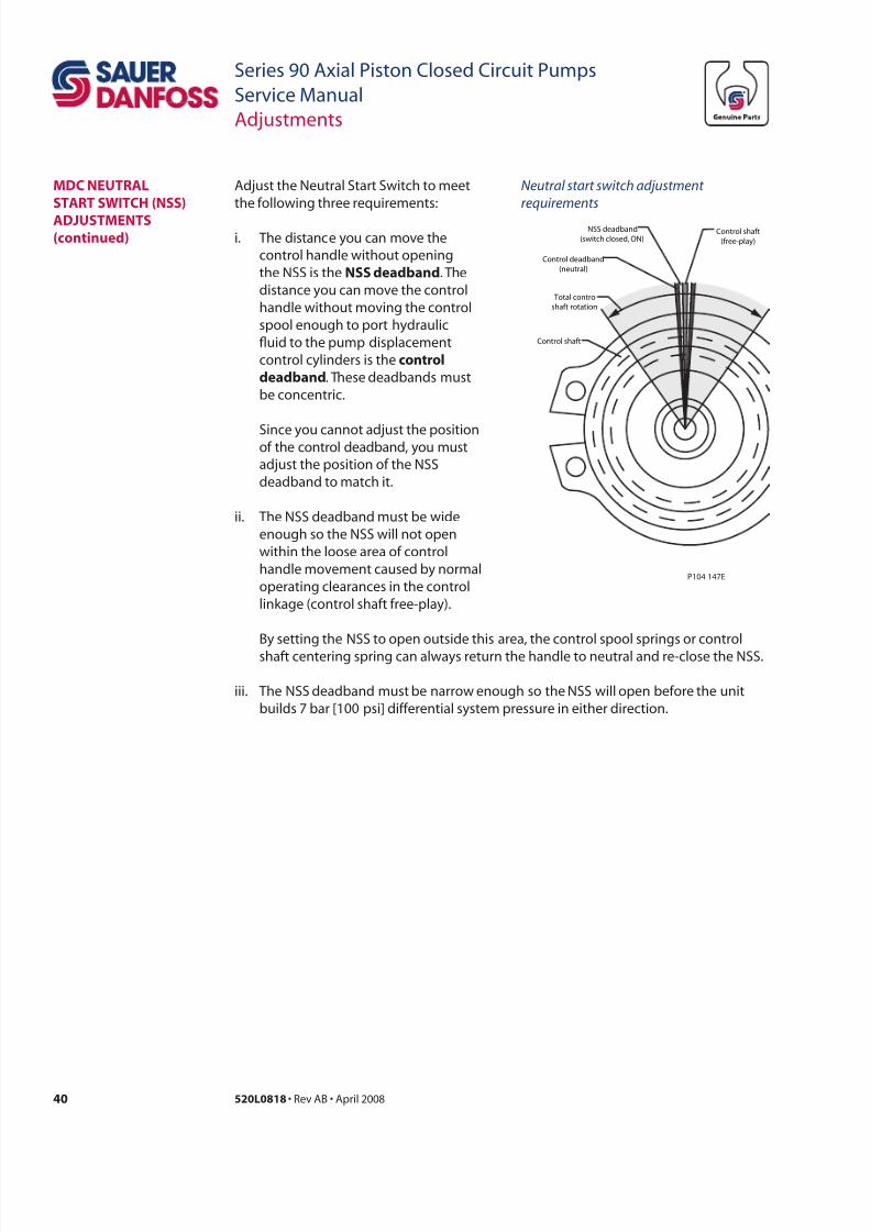
7/28/2019 Sauer90-ServiceManual.pdf
http://slidepdf.com/reader/full/sauer90-servicemanualpdf 40/72
40 520L0818 • Rev AB • April 2008
Series 90 Axial Piston Closed Circuit Pumps
Service Manual
Adjustments
Adjust the Neutral Start Switch to meet
the following three requirements:
i. The distance you can move the
control handle without opening
the NSS is the nss ddd. The
distance you can move the control
handle without moving the control
spool enough to port hydraulic
uid to the pump displacement
control cylinders is the crl
ddd. These deadbands must
be concentric.
Since you cannot adjust the positionof the control deadband, you must
adjust the position of the NSS
deadband to match it.
ii. The NSS deadband must be wide
enough so the NSS will not open
within the loose area of control
handle movement caused by normal
operating clearances in the control
linkage (control shaft free-play).
Control shaft
(free-play)
Control shaft
Total control
shaft rotation
Control deadband
(neutral)
NSS deadband
(switch closed, ON)
P104 147E
Neutral start switch adjustment
requirements
By setting the NSS to open outside this area, the control spool springs or control
shaft centering spring can always return the handle to neutral and re-close the NSS.
iii. The NSS deadband must be narrow enough so the NSS will open before the unit
builds 7 bar [100 psi] differential system pressure in either direction.
mDC neutRaL
staRt switCH (nss)
aDjustments(cd)
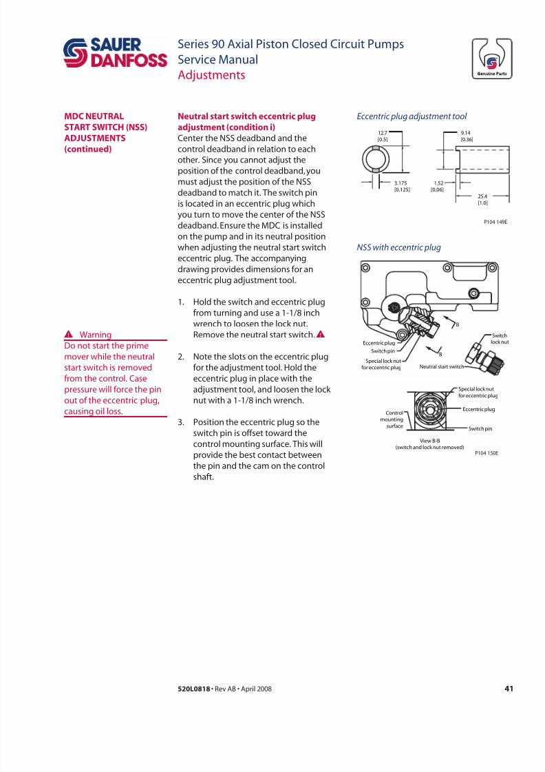
7/28/2019 Sauer90-ServiceManual.pdf
http://slidepdf.com/reader/full/sauer90-servicemanualpdf 41/72
41520L0818 • Rev AB • April 2008
Series 90 Axial Piston Closed Circuit Pumps
Service Manual
Adjustments
Center the NSS deadband and thecontrol deadband in relation to each
other. Since you cannot adjust the
position of the control deadband, you
must adjust the position of the NSS
deadband to match it. The switch pin
is located in an eccentric plug which
you turn to move the center of the NSS
deadband. Ensure the MDC is installed
on the pump and in its neutral position
when adjusting the neutral start switch
eccentric plug. The accompanying
drawing provides dimensions for aneccentric plug adjustment tool.
1. Hold the switch and eccentric plug
from turning and use a 1-1/8 inch
wrench to loosen the lock nut.
Remove the neutral start switch.WW Warning
Do not start the prime
mover while the neutral
start switch is removed
from the control. Case
pressure will force the pin
out of the eccentric plug,
causing oil loss.
2. Note the slots on the eccentric plug
for the adjustment tool. Hold the
eccentric plug in place with the
adjustment tool, and loosen the lock
nut with a 1-1/8 inch wrench.
3. Position the eccentric plug so the
switch pin is offset toward the
control mounting surface. This will
provide the best contact between
the pin and the cam on the control
shaft.
nrl r ch ccrc pl
d (cd )12.7[0.5]
9.14[0.36]
3.175
[0.125]
1.52
[0.06]
25.4
[1.0]
P104 149E
Eccentric plug adjustment tool
Neutral start switch
Switch
lock nutEccentric plug
Switch pin
Special lock nut
for eccentric plug
Eccentric plug
Switch pin
Special lock nut
for eccentric plug
Control
mounting
surface
View B-B
(switch and lock nut removed)P104 150E
B
B
NSS with eccentric plug
mDC neutRaL
staRt switCH (nss)
aDjustments(cd)
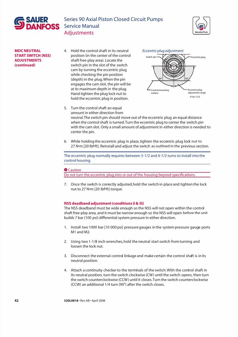
7/28/2019 Sauer90-ServiceManual.pdf
http://slidepdf.com/reader/full/sauer90-servicemanualpdf 42/72
42 520L0818 • Rev AB • April 2008
Series 90 Axial Piston Closed Circuit Pumps
Service Manual
Adjustments
The NSS deadband must be wide enough so the NSS will not open within the control
shaft free-play area, and it must be narrow enough so the NSS will open before the unit
builds 7 bar (100 psi) differential system pressure in either direction.
1. Install two 1000 bar [10 000 psi] pressure gauges in the system pressure gauge ports
M1 and M2.
2. Using two 1-1/8 inch wrenches, hold the neutral start switch from turning and
loosen the lock nut.
3. Disconnect the external control linkage and make certain the control shaft is in its
neutral position.
4. Attach a continuity checker to the terminals of the switch. With the control shaft in
its neutral position, turn the switch clockwise (CW) until the switch opens, then turn
the switch counterclockwise (CCW) until it closes. Turn the switch counterclockwise
(CCW) an additional 1/4 turn (90°) after the switch closes.
nss ddd d (cd & )
4. Hold the control shaft in its neutral
position (in the center of the control
shaft free-play area). Locate theswitch pin in the slot of the switch
cam by turning the eccentric plug
while checking the pin position
(depth) in the plug. When the pin
engages the cam slot, the pin will be
at its maximum depth in the plug.
Hand tighten the plug lock nut to
hold the eccentric plug in position.
5. Turn the control shaft an equal
amount in either direction from
CCaution
Do not turn the eccentric plug into or out of the housing beyond specications.
7. Once the switch is correctly adjusted, hold the switch in place and tighten the lock
nut to 27 N•m [20 lbf•ft] torque.
Eccentric plugSwitch pin
Eccentric plug
adjustment range
90°90°
Control mounting
surface
P104 151E
Eccentric plug adjustment
neutral. The switch pin should move out of the eccentric plug an equal distancewhen the control shaft is turned. Turn the eccentric plug to center the switch pin
with the cam slot. Only a small amount of adjustment in either direction is needed to
center the pin.
6. While holding the eccentric plug in place, tighten the eccentric plug lock nut to
27 N•m [20 lbf•ft]. Reinstall and adjust the switch as outlined in the previous section.
The eccentric plug normally requires between 5-1/2 and 6-1/2 turns to install into the
control housing.
mDC neutRaL
staRt switCH (nss)
aDjustments(cd)
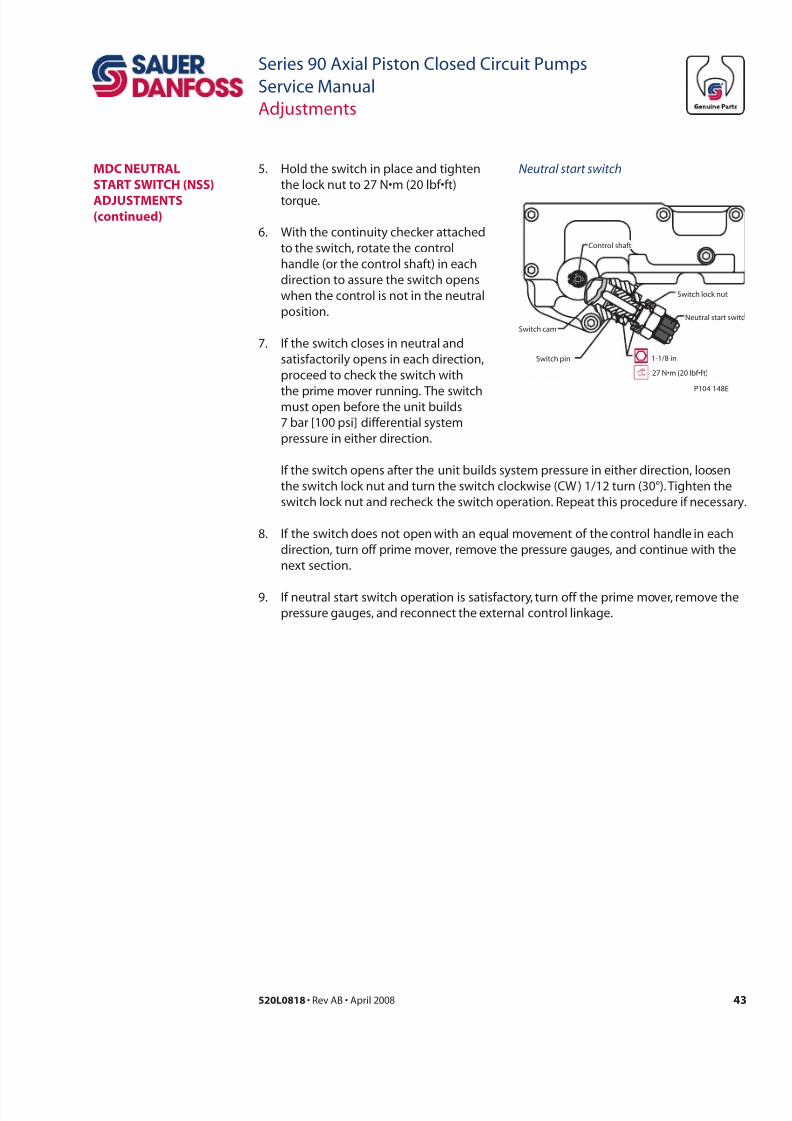
7/28/2019 Sauer90-ServiceManual.pdf
http://slidepdf.com/reader/full/sauer90-servicemanualpdf 43/72
43520L0818 • Rev AB • April 2008
Series 90 Axial Piston Closed Circuit Pumps
Service Manual
Adjustments
Switch pin 1-1/8 in
Neutral start switc
Switch lock nut
Control shaft
P104 148E
Switch cam
27 N•m (20 lbf•f t)
Neutral start switch5. Hold the switch in place and tighten
the lock nut to 27 N•m (20 lbf•ft)
torque.
6. With the continuity checker attached
to the switch, rotate the control
handle (or the control shaft) in each
direction to assure the switch opens
when the control is not in the neutral
position.
7. If the switch closes in neutral and
satisfactorily opens in each direction,
proceed to check the switch with
the prime mover running. The switchmust open before the unit builds
7 bar [100 psi] differential system
pressure in either direction.
If the switch opens after the unit builds system pressure in either direction, loosen
the switch lock nut and turn the switch clockwise (CW ) 1/12 turn (30°). Tighten the
switch lock nut and recheck the switch operation. Repeat this procedure if necessary.
8. If the switch does not open with an equal movement of the control handle in each
direction, turn off prime mover, remove the pressure gauges, and continue with the
next section.
9. If neutral start switch operation is satisfactory, turn off the prime mover, remove the
pressure gauges, and reconnect the external control linkage.
mDC neutRaL
staRt switCH (nss)
aDjustments(cd)
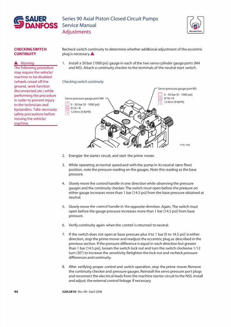
7/28/2019 Sauer90-ServiceManual.pdf
http://slidepdf.com/reader/full/sauer90-servicemanualpdf 44/72
44 520L0818 • Rev AB • April 2008
Series 90 Axial Piston Closed Circuit Pumps
Service Manual
Adjustments
Recheck switch continuity to determine whether additional adjustment of the eccentric
plug is necessary.WCHeCking switCH
Continuity
W Warning
The following procedure
may require the vehicle/
machine to be disabled
(wheels raised off the
ground, work function
disconnected, etc.) while
performing the procedure
in order to prevent injury
to the technician and
bystanders. Take necessary
safety precautions beforemoving the vehicle/
machine.
2. Energize the starter circuit, and start the prime mover.
3. While operating at normal speed and with the pump in its neutral (zero ow)
position, note the pressure reading on the gauges. Note this reading as the base
pressure.
4. Slowly move the control handle in one direction while observing the pressure
gauges and the continuity checker. The switch must open before the pressure on
either gauge increases more than 1 bar [14.5 psi] from the base pressure obtained at
neutral.
5. Slowly move the control handle in the opposite direction. Again, The switch must
open before the gauge pressure increases more than 1 bar [14.5 psi] from base
pressure.
6. Verify continuity again when the control is returned to neutral.
7. If the switch does not open at base pressure plus 0 to 1 bar [0 to 14.5 psi] in either
direction, stop the prime mover and readjust the eccentric plug as described in the
previous section. If the pressure difference is equal in each direction but greater
than 1 bar [14.5 psi], loosen the switch lock nut and turn the switch clockwise 1/12
turn (30°) to increase the sensitivity. Retighten the lock nut and recheck pressure
differences and continuity.
8. After verifying proper control and switch operation, stop the prime mover. Remove
the continuity checker and pressure gauges. Reinstall the servo pressure port plugs
and reconnect the electrical leads from the machine starter circuit to the NSS. Install
and adjust, the external control linkage if necessary.
Servo pressure gauge port M4
Servo pressure gauge port M5
GBtG
B
t
0 - 50 bar [0 - 1000 psi]
9/16-18
12 N•m [9 lbf•ft] 0 - 50 bar [0 - 1000 psi]9/16-18
12 N•m [9 lbf•ft]
P106 166E
Checking switch continuity
1. Install a 50 bar [1000 psi] gauge in each of the two servo cylinder gauge ports (M4
and M5). Attach a continuity checker to the terminals of the neutral start switch.
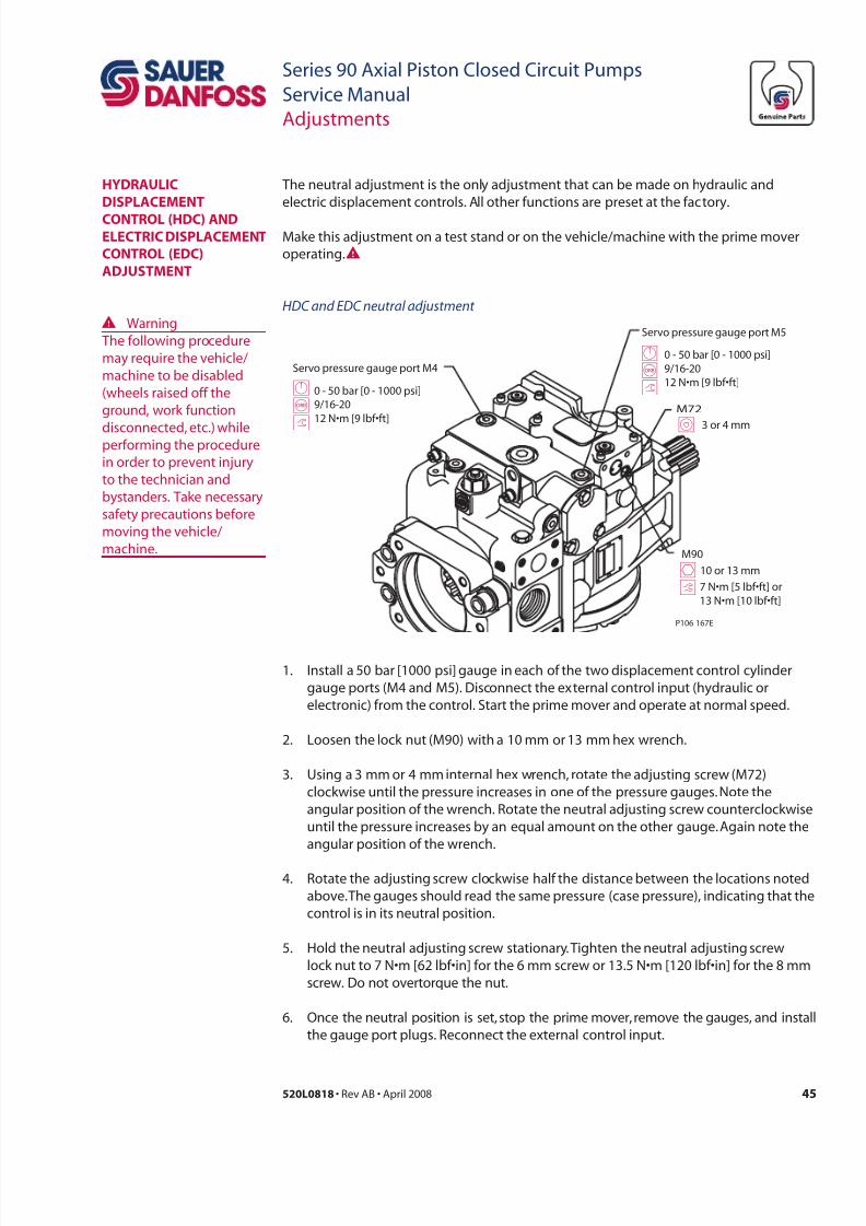
7/28/2019 Sauer90-ServiceManual.pdf
http://slidepdf.com/reader/full/sauer90-servicemanualpdf 45/72
45520L0818 • Rev AB • April 2008
Series 90 Axial Piston Closed Circuit Pumps
Service Manual
Adjustments
The neutral adjustment is the only adjustment that can be made on hydraulic and
electric displacement controls. All other functions are preset at the factory.
Make this adjustment on a test stand or on the vehicle/machine with the prime mover
operating.W
W Warning
The following procedure
may require the vehicle/
machine to be disabled
(wheels raised off the
ground, work function
disconnected, etc.) whileperforming the procedure
in order to prevent injury
to the technician and
bystanders. Take necessary
safety precautions before
moving the vehicle/
machine.
1. Install a 50 bar [1000 psi] gauge in each of the two displacement control cylinder
gauge ports (M4 and M5). Disconnect the external control input (hydraulic or
electronic) from the control. Start the prime mover and operate at normal speed.
2. Loosen the lock nut (M90) with a 10 mm or 13 mm hex wrench.
3. Using a 3 mm or 4 mm internal hex wrench, rotate the adjusting screw (M72)
clockwise until the pressure increases in one of the pressure gauges. Note the
angular position of the wrench. Rotate the neutral adjusting screw counterclockwise
until the pressure increases by an equal amount on the other gauge. Again note the
angular position of the wrench.
4. Rotate the adjusting screw clockwise half the distance between the locations noted
above. The gauges should read the same pressure (case pressure), indicating that the
control is in its neutral position.
5. Hold the neutral adjusting screw stationary. Tighten the neutral adjusting screw
lock nut to 7 N•m [62 lbf•in] for the 6 mm screw or 13.5 N•m [120 lbf•in] for the 8 mm
screw. Do not overtorque the nut.
6. Once the neutral position is set, stop the prime mover, remove the gauges, and install
the gauge port plugs. Reconnect the external control input.
HyDRauLiC
DisPLaCement
ContRoL (HDC) anDeLeCtRiC DisPLaCement
ContRoL (eDC)
aDjustment
Servo pressure gauge port M4
Servo pressure gauge port M5
GBtG
B
t
0 - 50 bar [0 - 1000 psi]
9/16-2012 N•m [9 lbf•ft]
0 - 50 bar [0 - 1000 psi]9/16-20
12 N•m [9 lbf•ft]
P106 167E
10 or 13 mm
7 N•m [5 lbf•ft] or
13 N•m [10 lbf•ft]
I 3 or 4 mm
M90
M72
th
HDC and EDC neutral adjustment
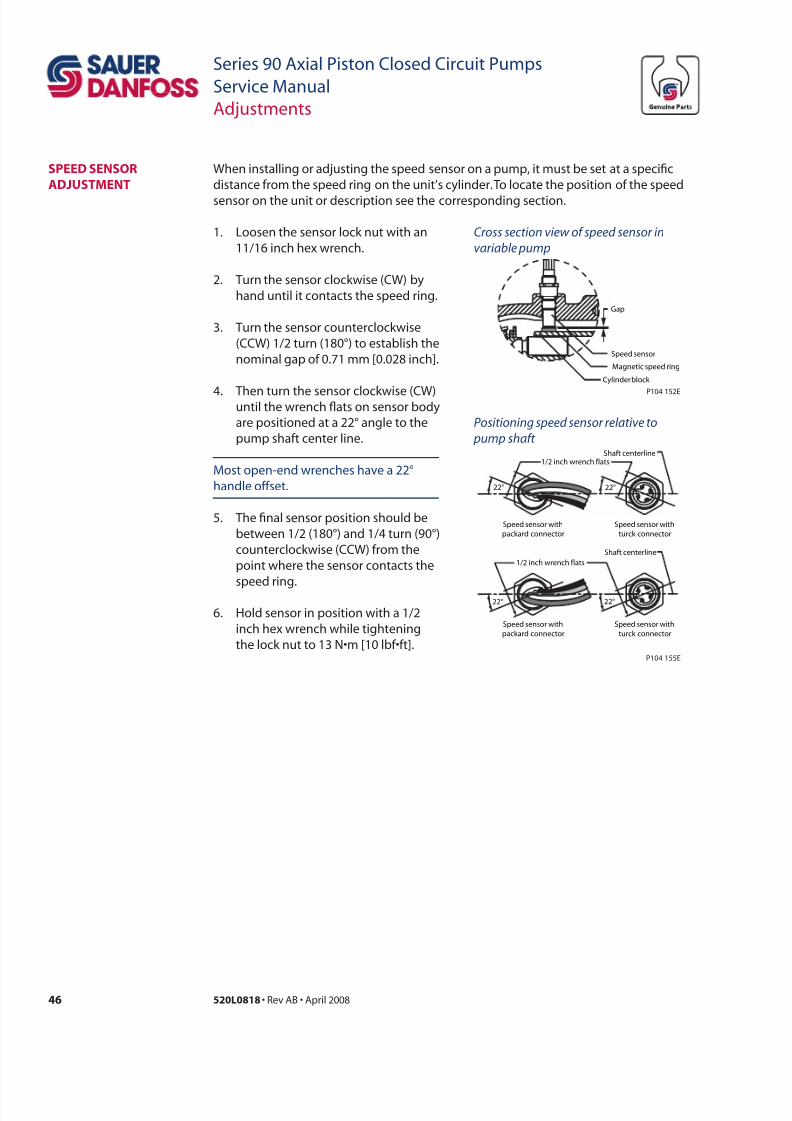
7/28/2019 Sauer90-ServiceManual.pdf
http://slidepdf.com/reader/full/sauer90-servicemanualpdf 46/72
46 520L0818 • Rev AB • April 2008
Series 90 Axial Piston Closed Circuit Pumps
Service Manual
Adjustments
1. Loosen the sensor lock nut with an
11/16 inch hex wrench.
2. Turn the sensor clockwise (CW) by
hand until it contacts the speed ring.
3. Turn the sensor counterclockwise
(CCW) 1/2 turn (180°) to establish the
nominal gap of 0.71 mm [0.028 inch].
4. Then turn the sensor clockwise (CW)until the wrench ats on sensor body
are positioned at a 22° angle to the
pump shaft center line.
Most open-end wrenches have a 22°
handle offset.
5. The nal sensor position should be
between 1/2 (180°) and 1/4 turn (90°)
counterclockwise (CCW) from the
point where the sensor contacts the
speed ring.
6. Hold sensor in position with a 1/2
inch hex wrench while tightening
the lock nut to 13 N•m [10 lbf•ft].
sPeeD sensoR
aDjustment
When installing or adjusting the speed sensor on a pump, it must be set at a specic
distance from the speed ring on the unit’s cylinder. To locate the position of the speed
sensor on the unit or description see the corresponding section.
Cross section view o speed sensor in
variable pump
Positioning speed sensor relative to
pump shat
Magnetic speed ring
Speed sensor
Gap
P104 152E
Cylinder block
1/2 inch wrench flats
22°
Speed sensor with
packard connector
22°
Speed sensor with
turck connector
1/2 inch wrench flats
22°
Speed sensor with
packard connector
22°
Speed sensor with
turck connector
Shaft centerline
Shaft centerline
P104 155E
7/28/2019 Sauer90-ServiceManual.pdf
http://slidepdf.com/reader/full/sauer90-servicemanualpdf 47/72
47520L0818 • Rev AB • April 2008
Series 90 Axial Piston Closed Circuit Pumps
Service Manual
Minor repair
stanDaRD PRoCeDuRes R h pp
Before working on the pump, clean the outside of the pump. If the pump has an auxiliary
pump attached, remove both pumps as a single unit. Tag and cap all hydraulic lines asthey are disconnected and plug all open ports to ensure that contamination does not
enter the system.
CC
Contamination can damage internal components and void your warranty. Take
precautions to ensure system cleanliness when removing and reinstalling system lines
Dl
1. With the prime mover off, thoroughly clean the outside of the pump.
2. Tag, cap, and disconnect each hydraulic line connected to the pump. As hydrauliclines are disconnected, plug each open port, to ensure that dirt and contamination
do not enter the system.
3. Remove the pump and its auxiliary pump (if applicable) as a single unit.
ipc
4. Ensure the work surface and surrounding area are clean and free of contaminants.
5. Inspect the system for contamination.
6. Look at the hydraulic uid for signs of system contamination, uid discoloration,
foam, sludge, or small metal particles.
Rl
7. Before replacing the pump on the machine, replace all lters and drain and ll the
hydraulic system with the correct hydraulic uid.
8. Flush the lines before replacing the hydraulic uid.
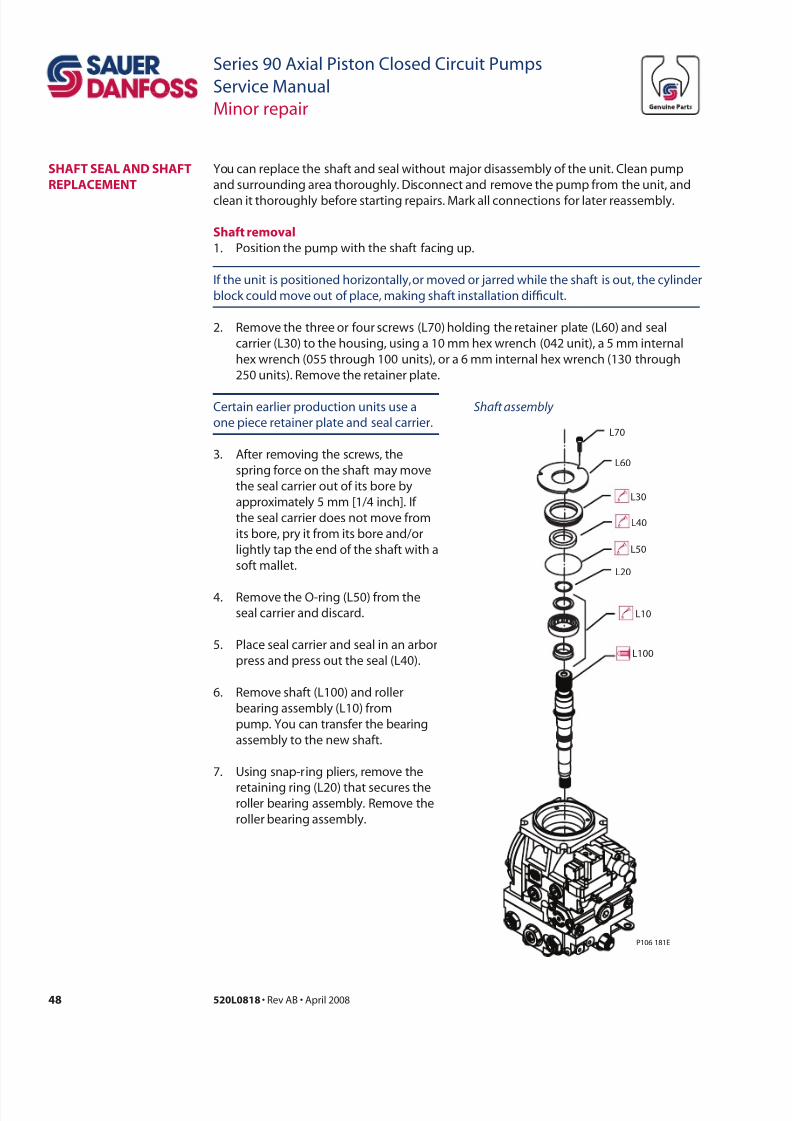
7/28/2019 Sauer90-ServiceManual.pdf
http://slidepdf.com/reader/full/sauer90-servicemanualpdf 48/72
48 520L0818 • Rev AB • April 2008
Series 90 Axial Piston Closed Circuit Pumps
Service Manual
Minor repair
sHat seaL anD sHat
RePLaCement
You can replace the shaft and seal without major disassembly of the unit. Clean pump
and surrounding area thoroughly. Disconnect and remove the pump from the unit, and
clean it thoroughly before starting repairs. Mark all connections for later reassembly.
sh rl
1. Position the pump with the shaft facing up.
If the unit is positioned horizontally, or moved or jarred while the shaft is out, the cylinder
block could move out of place, making shaft installation difcult.
2. Remove the three or four screws (L70) holding the retainer plate (L60) and seal
carrier (L30) to the housing, using a 10 mm hex wrench (042 unit), a 5 mm internal
hex wrench (055 through 100 units), or a 6 mm internal hex wrench (130 through
250 units). Remove the retainer plate.
L100
L10
L20
L50
L40
L30
L60
L70
P106 181E
Shat assembly Certain earlier production units use a
one piece retainer plate and seal carrier.
3. After removing the screws, the
spring force on the shaft may move
the seal carrier out of its bore by
approximately 5 mm [1/4 inch]. If
the seal carrier does not move from
its bore, pry it from its bore and/or
lightly tap the end of the shaft with a
soft mallet.
4. Remove the O-ring (L50) from the
seal carrier and discard.
5. Place seal carrier and seal in an arbor
press and press out the seal (L40).
6. Remove shaft (L100) and roller
bearing assembly (L10) from
pump. You can transfer the bearing
assembly to the new shaft.
7. Using snap-ring pliers, remove the
retaining ring (L20) that secures theroller bearing assembly. Remove the
roller bearing assembly.
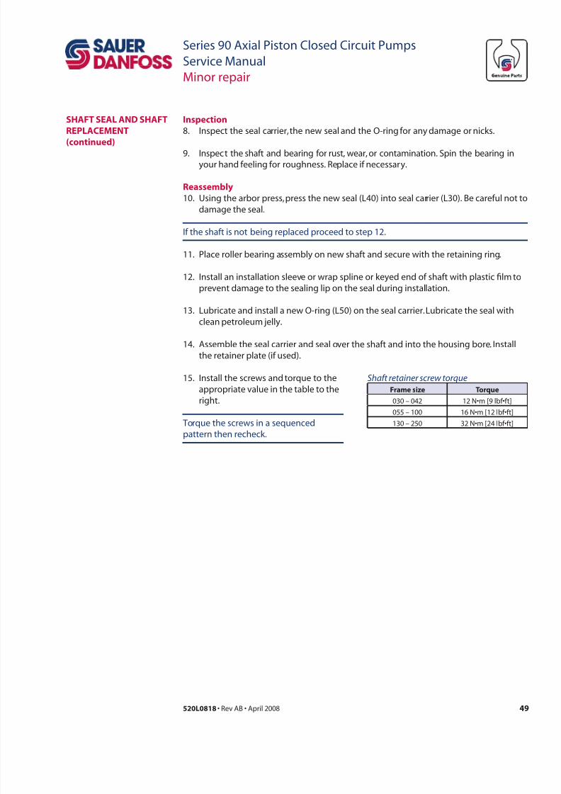
7/28/2019 Sauer90-ServiceManual.pdf
http://slidepdf.com/reader/full/sauer90-servicemanualpdf 49/72
49520L0818 • Rev AB • April 2008
Series 90 Axial Piston Closed Circuit Pumps
Service Manual
Minor repair
ipc
8. Inspect the seal carrier, the new seal and the O-ring for any damage or nicks.
9. Inspect the shaft and bearing for rust, wear, or contamination. Spin the bearing in
your hand feeling for roughness. Replace if necessary.
Rl
10. Using the arbor press, press the new seal (L40) into seal carrier (L30). Be careful not to
damage the seal.
If the shaft is not being replaced proceed to step 12.
11. Place roller bearing assembly on new shaft and secure with the retaining ring.
12. Install an installation sleeve or wrap spline or keyed end of shaft with plastic lm toprevent damage to the sealing lip on the seal during installation.
13. Lubricate and install a new O-ring (L50) on the seal carrier. Lubricate the seal with
clean petroleum jelly.
14. Assemble the seal carrier and seal over the shaft and into the housing bore. Install
the retainer plate (if used).
15. Install the screws and torque to the
appropriate value in the table to the
right.
Shat retainer screw torque
r tr
030 – 042 12 N•m [9 lbf•ft]
055 – 100 16 N•m [12 lbf•ft]
130 – 250 32 N•m [24 lbf•ft] Torque the screws in a sequenced
pattern then recheck.
sHat seaL anD sHat
RePLaCement
(cd)
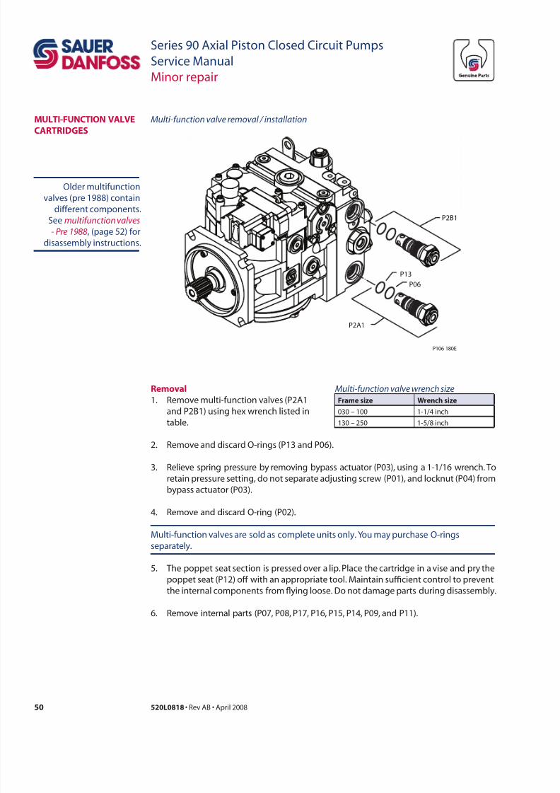
7/28/2019 Sauer90-ServiceManual.pdf
http://slidepdf.com/reader/full/sauer90-servicemanualpdf 50/72
50 520L0818 • Rev AB • April 2008
Series 90 Axial Piston Closed Circuit Pumps
Service Manual
Minor repair
2. Remove and discard O-rings (P13 and P06).
3. Relieve spring pressure by removing bypass actuator (P03), using a 1-1/16 wrench. To
retain pressure setting, do not separate adjusting screw (P01), and locknut (P04) from
bypass actuator (P03).
4. Remove and discard O-ring (P02).
Multi-function valves are sold as complete units only. You may purchase O-rings
separately.
5. The poppet seat section is pressed over a lip. Place the cartridge in a vise and pry the
poppet seat (P12) off with an appropriate tool. Maintain sufcient control to prevent
the internal components from ying loose. Do not damage parts during disassembly.
6. Remove internal parts (P07, P08, P17, P16, P15, P14, P09, and P11).
muLti-unCtion vaLve
CaRtRiDges
Multi-unction valve wrench size
r wrch
030 – 100 1-1/4 inch
130 – 250 1-5/8 inch
Rl
1. Remove multi-function valves (P2A1
and P2B1) using hex wrench listed in
table.
P2B1
P2A1
P06
P13
P106 180E
Multi-unction valve removal / installation
Older multifunction
valves (pre 1988) contain
different components.
See multiunction valves
- Pre 1988, (page 52) for
disassembly instructions.
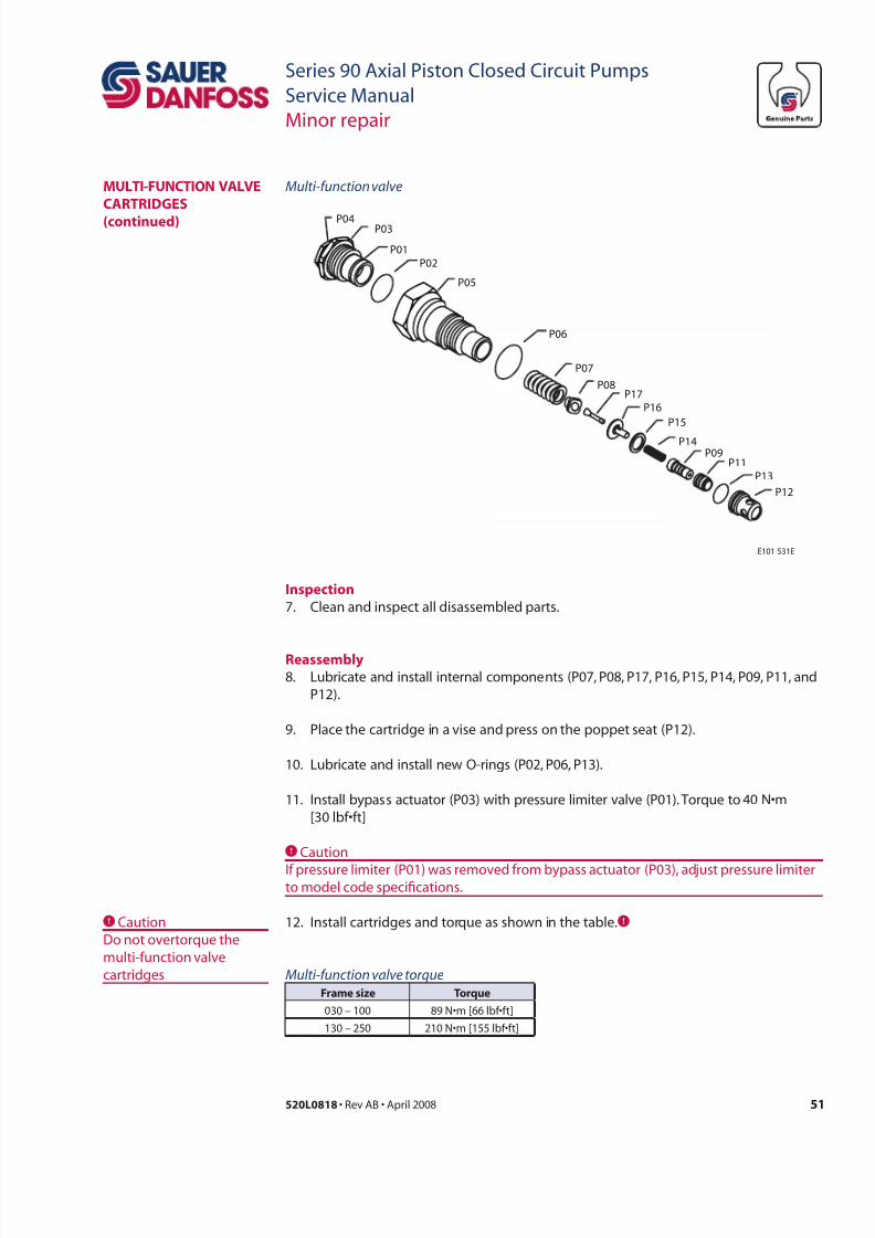
7/28/2019 Sauer90-ServiceManual.pdf
http://slidepdf.com/reader/full/sauer90-servicemanualpdf 51/72
51520L0818 • Rev AB • April 2008
Series 90 Axial Piston Closed Circuit Pumps
Service Manual
Minor repair
P12
E101 531E
P13
P14
P09P11
P06
P05
P07
P15
P16
P17P08
P03P04
P02
P01
Multi-unction valvemuLti-unCtion vaLve
CaRtRiDges
(cd)
ipc
7. Clean and inspect all disassembled parts.
Rl
8. Lubricate and install internal components (P07, P08, P17, P16, P15, P14, P09, P11, and
P12).
9. Place the cartridge in a vise and press on the poppet seat (P12).
10. Lubricate and install new O-rings (P02, P06, P13).
11. Install bypass actuator (P03) with pressure limiter valve (P01). Torque to 40 N•m
[30 lbf•ft]
CCaution
If pressure limiter (P01) was removed from bypass actuator (P03), adjust pressure limiterto model code specications.
12. Install cartridges and torque as shown in the table.C
Multi-unction valve torque
r tr
030 – 100 89 N•m [66 lbf•ft]
130 – 250 210 N•m [155 lbf•ft]
CCaution
Do not overtorque the
multi-function valve
cartridges
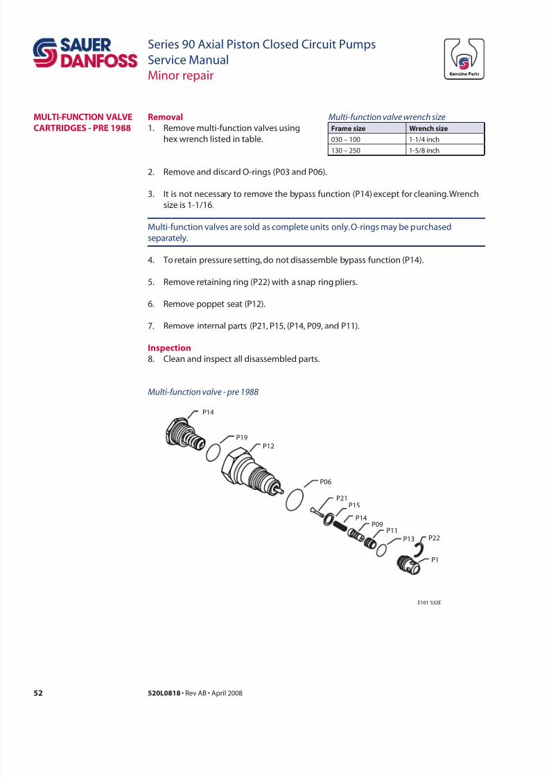
7/28/2019 Sauer90-ServiceManual.pdf
http://slidepdf.com/reader/full/sauer90-servicemanualpdf 52/72
52 520L0818 • Rev AB • April 2008
Series 90 Axial Piston Closed Circuit Pumps
Service Manual
Minor repair
muLti-unCtion vaLve
CaRtRiDges - PRe 1988
P1
E101 532E
P13
P14
P09P11
P06
P12
P15
P21
P14
P19
P22
Multi-unction valve - pre 1988
2. Remove and discard O-rings (P03 and P06).
3. It is not necessary to remove the bypass function (P14) except for cleaning. Wrench
size is 1-1/16.
Multi-function valves are sold as complete units only. O-rings may be purchased
separately.
4. To retain pressure setting, do not disassemble bypass function (P14).
5. Remove retaining ring (P22) with a snap ring pliers.
6. Remove poppet seat (P12).
7. Remove internal parts (P21, P15, (P14, P09, and P11).
ipc
8. Clean and inspect all disassembled parts.
Multi-unction valve wrench size
r wrch
030 – 100 1-1/4 inch
130 – 250 1-5/8 inch
Rl
1. Remove multi-function valves using
hex wrench listed in table.
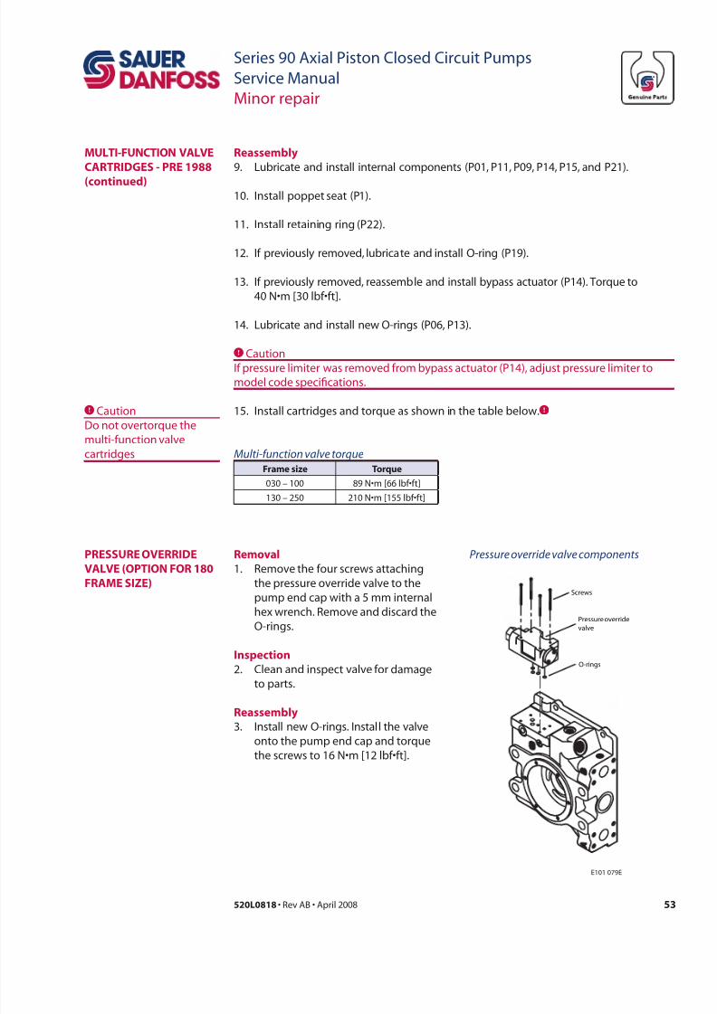
7/28/2019 Sauer90-ServiceManual.pdf
http://slidepdf.com/reader/full/sauer90-servicemanualpdf 53/72
53520L0818 • Rev AB • April 2008
Series 90 Axial Piston Closed Circuit Pumps
Service Manual
Minor repair
Rl
1. Remove the four screws attaching
the pressure override valve to the
pump end cap with a 5 mm internal
hex wrench. Remove and discard the
O-rings.
ipc
2. Clean and inspect valve for damage
to parts.
Rl3. Install new O-rings. Install the valve
onto the pump end cap and torque
the screws to 16 N•m [12 lbf•ft].
PRessuRe oveRRiDe
vaLve (oPtion oR 180
Rame size)
Pressure override valve components
Pressure override
valve
O-rings
Screws
E101 079E
Rl
9. Lubricate and install internal components (P01, P11, P09, P14, P15, and P21).
10. Install poppet seat (P1).
11. Install retaining ring (P22).
12. If previously removed, lubricate and install O-ring (P19).
13. If previously removed, reassemble and install bypass actuator (P14). Torque to
40 N•m [30 lbf•ft].
14. Lubricate and install new O-rings (P06, P13).
CCautionIf pressure limiter was removed from bypass actuator (P14), adjust pressure limiter to
model code specications.
15. Install cartridges and torque as shown in the table below.C
Multi-unction valve torque
r tr
030 – 100 89 N•m [66 lbf•ft]
130 – 250 210 N•m [155 lbf•ft]
CCaution
Do not overtorque the
multi-function valve
cartridges
muLti-unCtion vaLve
CaRtRiDges - PRe 1988
(cd)
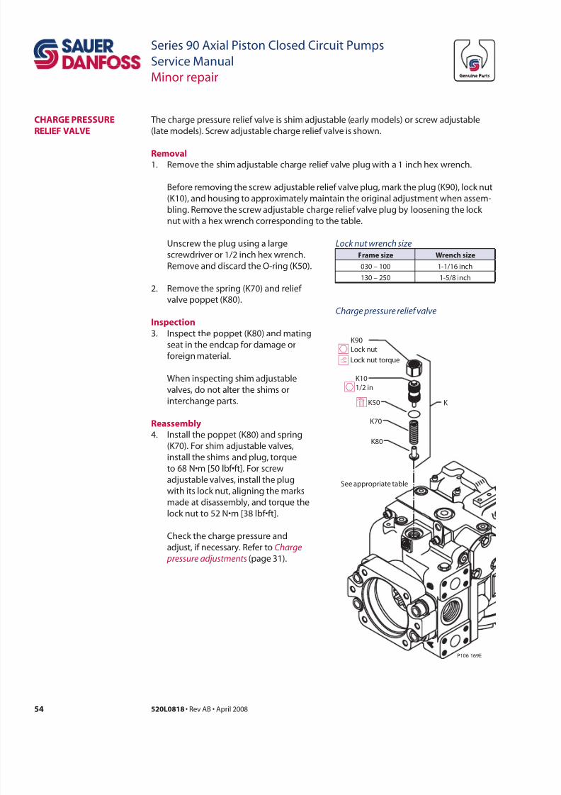
7/28/2019 Sauer90-ServiceManual.pdf
http://slidepdf.com/reader/full/sauer90-servicemanualpdf 54/72
54 520L0818 • Rev AB • April 2008
Series 90 Axial Piston Closed Circuit Pumps
Service Manual
Minor repair
The charge pressure relief valve is shim adjustable (early models) or screw adjustable
(late models). Screw adjustable charge relief valve is shown.
Rl
1. Remove the shim adjustable charge relief valve plug with a 1 inch hex wrench.
Before removing the screw adjustable relief valve plug, mark the plug (K90), lock nut
(K10), and housing to approximately maintain the original adjustment when assem-
bling. Remove the screw adjustable charge relief valve plug by loosening the lock
nut with a hex wrench corresponding to the table.
CHaRge PRessuRe
ReLie vaLve
Unscrew the plug using a large
screwdriver or 1/2 inch hex wrench.
Remove and discard the O-ring (K50).
2. Remove the spring (K70) and relief
valve poppet (K80).
ipc
3. Inspect the poppet (K80) and mating
seat in the endcap for damage or
foreign material.
When inspecting shim adjustable
valves, do not alter the shims or
interchange parts.
Rl
4. Install the poppet (K80) and spring
(K70). For shim adjustable valves,
install the shims and plug, torque
to 68 N•m [50 lbf•ft]. For screw
adjustable valves, install the plug
with its lock nut, aligning the marks
made at disassembly, and torque the
lock nut to 52 N•m [38 lbf•ft].
Check the charge pressure and
adjust, if necessary. Refer to Charge
pressure adjustments (page 31).
Lock nut wrench size
r wrch
030 – 100 1-1/16 inch
130 – 250 1-5/8 inch
K10
1/2 in
K90
Lock nut
Lock nut torque
P106 169E
See appropriate table
K K50
K70
K80
d
h
ht
Charge pressure relie valve
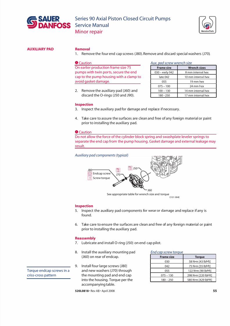
7/28/2019 Sauer90-ServiceManual.pdf
http://slidepdf.com/reader/full/sauer90-servicemanualpdf 55/72
55520L0818 • Rev AB • April 2008
Series 90 Axial Piston Closed Circuit Pumps
Service Manual
Minor repair
auXiLiaRy PaD Rl
1. Remove the four end cap screws (J80). Remove and discard special washers (J70).
Aux. pad screw wrench size
r wrch
030 – early 042 8 mm internal hex
late 042 10 mm internal hex
055 19 mm hex
075 – 100 24 mm hex
100 – 130 14 mm internal hex
180 –250 17 mm internal hex
2. Remove the auxiliary pad (J60) and
discard the O-rings (J50 and J90).
Auxiliary pad components (typical)
J70
J60
J50
J80
E101 084E
Endcap screw
Screw torque
See appropriate table for wrench size and torque
CCaution
On earlier production frame size 75
pumps with twin ports, secure the end
cap to the pump housing with a clamp to
avoid gasket damage.
CCaution
Do not allow the force of the cylinder block spring and swashplate leveler springs to
separate the end cap from the pump housing. Gasket damage and external leakage may
result.
ipc
3. Inspect the auxiliary pad for damage and replace if necessary.
4. Take care to assure the surfaces are clean and free of any foreign material or paint
prior to installing the auxiliary pad.
8. Install the auxiliary mounting pad
(J60) on rear of endcap.
ipc
5. Inspect the auxiliary pad components for wear or damage and replace if any is
found.
6. Take care to ensure the surfaces are clean and free of any foreign material or paint
prior to installing the auxiliary pad.
Rl
7. Lubricate and install O-ring (J50) on end cap pilot.
9. Install four large screws (J80)
and new washers (J70) through
the mounting pad and end cap
into the housing. Torque per the
accompanying table.
End cap screw torque
r tr
030 58 N•m [43 lbf•ft]
042 75 N•m [55 lbf•ft]
055 122 N•m [90 lbf•ft]
075 – 130 298 N•m [220 lbf•ft]
180 – 250 580 N•m [429 lbf•ft]
Torque endcap screws in a
criss-cross pattern
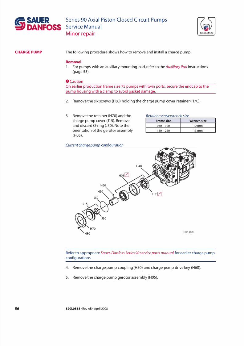
7/28/2019 Sauer90-ServiceManual.pdf
http://slidepdf.com/reader/full/sauer90-servicemanualpdf 56/72
56 520L0818 • Rev AB • April 2008
Series 90 Axial Piston Closed Circuit Pumps
Service Manual
Minor repair
The following procedure shows how to remove and install a charge pump.
Rl1. For pumps with an auxiliary mounting pad, refer to the Auxiliary Pad instructions
(page 55).
CCaution
On earlier production frame size 75 pumps with twin ports, secure the endcap to the
pump housing with a clamp to avoid gasket damage.
2. Remove the six screws (H80) holding the charge pump cover retainer (H70).
CHaRge PumP
3. Remove the retainer (H70) and the
charge pump cover (J15). Removeand discard O-ring (J50). Note the
orientation of the gerotor assembly
(H05).
Retainer screw wrench size
r wrch 030 – 100 10 mm
130 – 250 13 mm
Refer to appropriate Sauer-Danoss Series 90 service parts manual for earlier charge pump
congurations.
4. Remove the charge pump coupling (H50) and charge pump drive key (H60).
5. Remove the charge pump gerotor assembly (H05).
E101 082EH80
H70
J15
J30
J50
H50
H60
H05
H40
H31
Current charge pump confguration
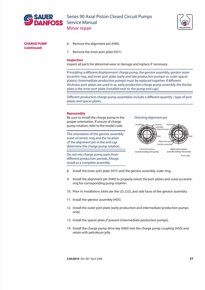
7/28/2019 Sauer90-ServiceManual.pdf
http://slidepdf.com/reader/full/sauer90-servicemanualpdf 57/72
57520L0818 • Rev AB • April 2008
Series 90 Axial Piston Closed Circuit Pumps
Service Manual
Minor repair
If installing a different displacement charge pump, the gerotor assembly, gerotor outer
eccentric ring, and inner port plate (early and late production pumps) or outer spacer
plate(s) (intermediate production pumps) must be replaced together. If different
thickness port plates are used in an early production charge pump assembly, the thicker
plate is the inner port plate (installed next to the pump end cap).
Different production charge pump assemblies include a different quantity / type of port
plates and spacer plates.
Rl
Be sure to install the charge pump in the
proper orientation. If unsure of charge
pump rotation, refer to the model code.
The orientation of the gerotor assembly
outer eccentric ring and the location
of the alignment pin in the end cap
determine the charge pump rotation..
Do not mix charge pump parts from
different production periods. Always
install as a complete assembly.
6. Remove the alignment pin (H40).
7. Remove the inner port plate (H31).
ipc
Inspect all parts for abnormal wear or damage and replace if necessary.
CHaRge PumP
(cd)
Orienting alignment pin
Inlet
Discharge
Alignment pin
Gerotor assembly
Right hand rotation
(outside looking into pump)
Gerotor
assembly
Inlet
Discharge
Left hand rotation
(outside looking into pump)
Alignment pin
P104 160E
8. Install the inner port plate (H31) and the gerotor assembly outer ring.
9. Install the alignment pin (H40) to properly orient the port plates and outer eccentric
ring for corresponding pump rotation.
10. Prior to installation, lubricate the I.D., O.D., and side faces of the gerotor assembly.
11. Install the gerotor assembly (H05).
12. Install the outer port plate (early production and intermediate production pumps
only).
13. Install the spacer plate, if present (intermediate production pumps).
14. Install the charge pump drive key (H60) into the charge pump coupling (H50) and
retain with petroleum jelly.
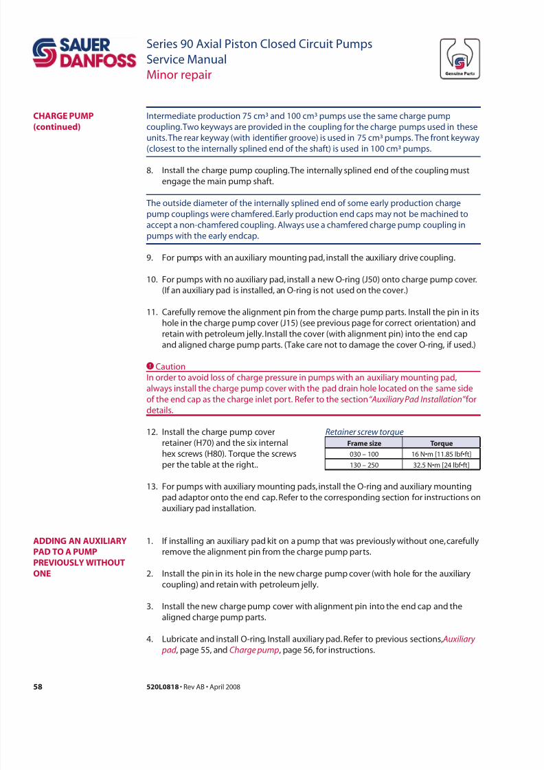
7/28/2019 Sauer90-ServiceManual.pdf
http://slidepdf.com/reader/full/sauer90-servicemanualpdf 58/72
58 520L0818 • Rev AB • April 2008
Series 90 Axial Piston Closed Circuit Pumps
Service Manual
Minor repair
Intermediate production 75 cm³ and 100 cm³ pumps use the same charge pump
coupling. Two keyways are provided in the coupling for the charge pumps used in these
units. The rear keyway (with identier groove) is used in 75 cm³ pumps. The front keyway(closest to the internally splined end of the shaft) is used in 100 cm³ pumps.
8. Install the charge pump coupling. The internally splined end of the coupling must
engage the main pump shaft.
The outside diameter of the internally splined end of some early production charge
pump couplings were chamfered. Early production end caps may not be machined to
accept a non-chamfered coupling. Always use a chamfered charge pump coupling in
pumps with the early endcap.
9. For pumps with an auxiliary mounting pad, install the auxiliary drive coupling.
10. For pumps with no auxiliary pad, install a new O-ring (J50) onto charge pump cover.
(If an auxiliary pad is installed, an O-ring is not used on the cover.)
11. Carefully remove the alignment pin from the charge pump parts. Install the pin in its
hole in the charge pump cover (J15) (see previous page for correct orientation) and
retain with petroleum jelly. Install the cover (with alignment pin) into the end cap
and aligned charge pump parts. (Take care not to damage the cover O-ring, if used.)
CCaution
In order to avoid loss of charge pressure in pumps with an auxiliary mounting pad,
always install the charge pump cover with the pad drain hole located on the same side
of the end cap as the charge inlet port. Refer to the section “Auxiliary Pad Installation” for
details.
12. Install the charge pump cover
retainer (H70) and the six internal
hex screws (H80). Torque the screws
per the table at the right..
13. For pumps with auxiliary mounting pads, install the O-ring and auxiliary mounting
pad adaptor onto the end cap. Refer to the corresponding section for instructions on
auxiliary pad installation.
Retainer screw torque
r tr
030 – 100 16 N•m [11.85 lbf•ft]
130 – 250 32.5 N•m [24 lbf•ft]
CHaRge PumP
(cd)
aDDing an auXiLiaRyPaD to a PumP
PReviousLy witHout
one
1. If installing an auxiliary pad kit on a pump that was previously without one, carefullyremove the alignment pin from the charge pump parts.
2. Install the pin in its hole in the new charge pump cover (with hole for the auxiliary
coupling) and retain with petroleum jelly.
3. Install the new charge pump cover with alignment pin into the end cap and the
aligned charge pump parts.
4. Lubricate and install O-ring. Install auxiliary pad. Refer to previous sections, Auxiliary
pad , page 55, and Charge pump, page 56, for instructions.
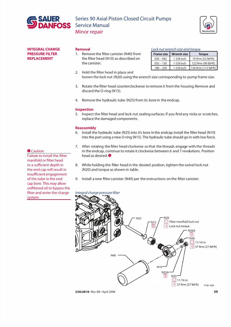
7/28/2019 Sauer90-ServiceManual.pdf
http://slidepdf.com/reader/full/sauer90-servicemanualpdf 59/72
59520L0818 • Rev AB • April 2008
Series 90 Axial Piston Closed Circuit Pumps
Service Manual
Minor repair
integRaL CHaRge
PRessuRe iLteR
RePLaCement
Rl
1. Remove the lter canister (N40) from
the lter head (N10) as described onthe canister.
2. Hold the lter head in place and
N25
N15
N20
N10
N40
N35
N36A
N36
N35A
11/16 in
37 N•m [27 lbf•f t]
11/16 in
37 N•m [27 lbf•f t]
Filter manifold lock nut
Lock nut torque
P106 182E
Integral charge pressure flter
Rl
6. Install the hydraulic tube (N25) into it’s bore in the endcap. Install the lter head (N10)
into the port using a new O-ring (N15). The hydraulic tube should go in with low force.
7. After rotating the lter head clockwise so that the threads engage with the threads
in the endcap, continue to rotate it clockwise between 6 and 7 revolutions. Position
head as desired.C
8. While holding the lter head in the desired position, tighten the swivel lock nut
(N20) and torque as shown in table.
9. Install a new lter canister (N40) per the instructions on the lter canister.
Lock nut wrench size and torque
r wrch tr
030 – 042 1-3/8 inch 70 N•m [52 lbf•ft]
055 – 130 1-5/8 inch 122 N•m [90 lbf•ft]
180 – 250 1-5/8 inch 156 N•m [115 lbf•ft ]
loosen the lock nut (N20) using the wrench size corresponding to pump frame size.
3. Rotate the lter head counterclockwise to remove it from the housing. Remove and
discard the O-ring (N15).
4. Remove the hydraulic tube (N25) from its bore in the endcap.
ipc
5. Inspect the lter head and lock nut sealing surfaces. If you nd any nicks or scratches,replace the damaged components.
CCaution
Failure to install the lter
manifold or lter head
to a sufcient depth in
the end cap will result in
insufcient engagement
of the tube in the end
cap bore. This may allow
unltered oil to bypass the
lter and enter the charge
system.
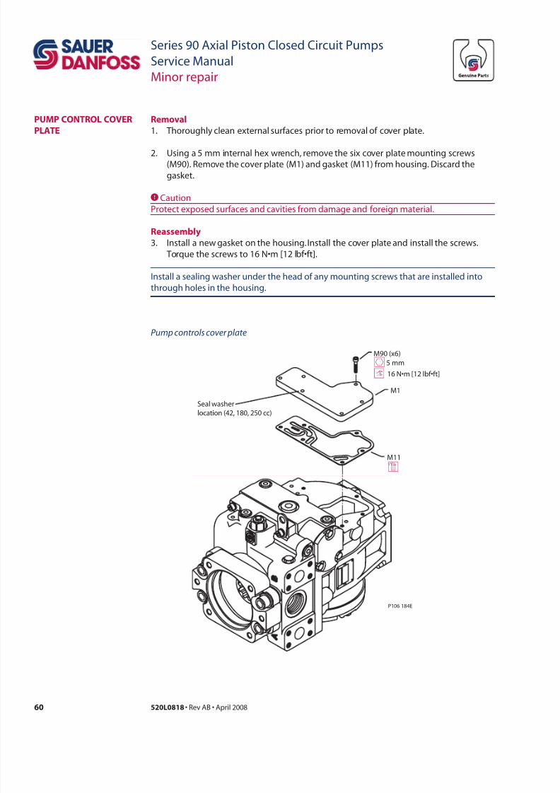
7/28/2019 Sauer90-ServiceManual.pdf
http://slidepdf.com/reader/full/sauer90-servicemanualpdf 60/72
60 520L0818 • Rev AB • April 2008
Series 90 Axial Piston Closed Circuit Pumps
Service Manual
Minor repair
Rl
1. Thoroughly clean external surfaces prior to removal of cover plate.
2. Using a 5 mm internal hex wrench, remove the six cover plate mounting screws
(M90). Remove the cover plate (M1) and gasket (M11) from housing. Discard the
gasket.
CCaution
Protect exposed surfaces and cavities from damage and foreign material.
Rl
3. Install a new gasket on the housing. Install the cover plate and install the screws.
Torque the screws to 16 N•m [12 lbf•ft].
Install a sealing washer under the head of any mounting screws that are installed intothrough holes in the housing.
PumP ContRoL CoveR
PLate
P106 184E
M90 (x6)
M1
M11
d
h5 mm
Seal washer
location (42, 180, 250 cc)
16 N•m [12 lbf•ft]
Pump controls cover plate
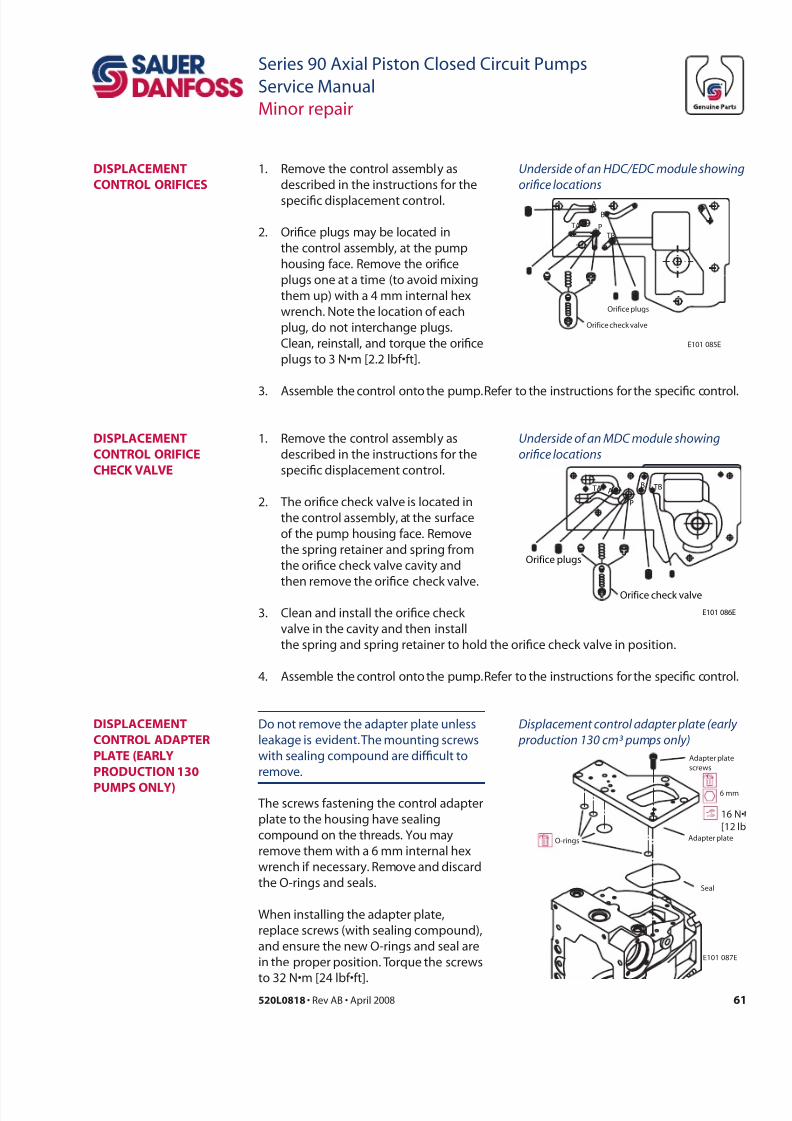
7/28/2019 Sauer90-ServiceManual.pdf
http://slidepdf.com/reader/full/sauer90-servicemanualpdf 61/72
61520L0818 • Rev AB • April 2008
Series 90 Axial Piston Closed Circuit Pumps
Service Manual
Minor repair
1. Remove the control assembly as
described in the instructions for the
specic displacement control.
2. Orice plugs may be located in
the control assembly, at the pump
housing face. Remove the orice
plugs one at a time (to avoid mixing
them up) with a 4 mm internal hex
wrench. Note the location of each
plug, do not interchange plugs.
Clean, reinstall, and torque the orice
plugs to 3 N•m [2.2 lbf•ft].
DisPLaCement
ContRoL oRiiCes
Underside o an HDC/EDC module showing
orifce locations
P
B
A
TB
TA
Orifice check valve
Orifice plugs
E101 085E
Do not remove the adapter plate unless
leakage is evident. The mounting screws
with sealing compound are difcult to
remove.
The screws fastening the control adapter
plate to the housing have sealing
compound on the threads. You may
remove them with a 6 mm internal hex
wrench if necessary. Remove and discard
the O-rings and seals.
When installing the adapter plate,
replace screws (with sealing compound),
and ensure the new O-rings and seal are
in the proper position. Torque the screws
to 32 N•m [24 lbf•ft].
DisPLaCement
ContRoL oRiiCe
CHeCk vaLve
DisPLaCement
ContRoL aDaPteR
PLate (eaRLy
PRoDuCtion 130
PumPs onLy)
Underside o an MDC module showing
orifce locations
Displacement control adapter plate (early
production 130 cm³ pumps only)
P
BA
TB TA
Orifice check valve
Orifice plugs
E101 086E
E101 087E
Adapter plate
screws
Adapter plate
Seal
O-rings
6 mm
16 N•
[12 lb
1. Remove the control assembly as
described in the instructions for the
specic displacement control.
2. The orice check valve is located in
the control assembly, at the surface
of the pump housing face. Remove
the spring retainer and spring from
the orice check valve cavity and
then remove the orice check valve.
3. Clean and install the orice check
valve in the cavity and then install
the spring and spring retainer to hold the orice check valve in position.
4. Assemble the control onto the pump. Refer to the instructions for the specic control.
3. Assemble the control onto the pump. Refer to the instructions for the specic control.
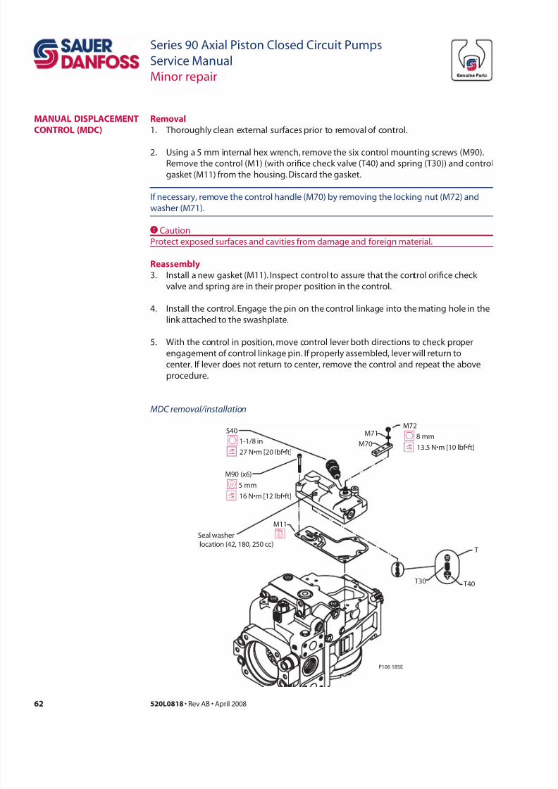
7/28/2019 Sauer90-ServiceManual.pdf
http://slidepdf.com/reader/full/sauer90-servicemanualpdf 62/72
62 520L0818 • Rev AB • April 2008
Series 90 Axial Piston Closed Circuit Pumps
Service Manual
Minor repair
Rl
1. Thoroughly clean external surfaces prior to removal of control.
2. Using a 5 mm internal hex wrench, remove the six control mounting screws (M90).
Remove the control (M1) (with orice check valve (T40) and spring (T30)) and control
gasket (M11) from the housing. Discard the gasket.
If necessary, remove the control handle (M70) by removing the locking nut (M72) and
washer (M71).
CCaution
Protect exposed surfaces and cavities from damage and foreign material.
Rl
3. Install a new gasket (M11). Inspect control to assure that the control orice check valve and spring are in their proper position in the control.
4. Install the control. Engage the pin on the control linkage into the mating hole in the
link attached to the swashplate.
5. With the control in position, move control lever both directions to check proper
engagement of control link age pin. If properly assembled, lever will return to
center. If lever does not return to center, remove the control and repeat the above
procedure.
manuaL DisPLaCement
ContRoL (mDC)
P106 185E
T
T30 T40
M90 (x6)
M11
M70
M72M71 S40
Seal washer
location (42, 180, 250 cc)
d
I5 mm
h1-1/8 in h8 mm
13.5 N•m [10 lbf•ft]
16 N•m [12 lbf•ft]
27 N•m [20 lbf•ft]
MDC removal/installation
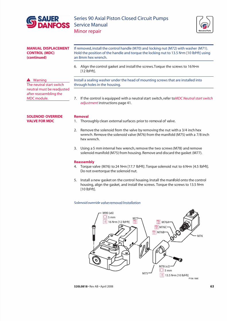
7/28/2019 Sauer90-ServiceManual.pdf
http://slidepdf.com/reader/full/sauer90-servicemanualpdf 63/72
63520L0818 • Rev AB • April 2008
Series 90 Axial Piston Closed Circuit Pumps
Service Manual
Minor repair
Install a sealing washer under the head of mounting screws that are installed into
through holes in the housing.
7. If the control is equipped with a neutral start switch, refer to MDC Neutral start switch
adjustment instructions page 41.
soLenoiD oveRRiDe
vaLve oR mDC
Rl
1. Thoroughly clean external surfaces prior to removal of valve.
2. Remove the solenoid from the valve by removing the nut with a 3/4 inch hex
wrench. Remove the solenoid valve (M76) from the manifold (M75) with a 7/8 inch
hex wrench.
3. Using a 5 mm internal hex wrench, remove the two screws (M78) and remove
solenoid manifold (M75) from housing. Remove and discard the gasket (M77).
Rl
4. Torque valve (M76) to 24 N•m [17.7 lbf•ft]. Torque solenoid nut to 6 N•m [4.5 lbf•ft].
Do not overtorque the solenoid nut.
5. Install a new gasket on the control housing. Install the manifold onto the control
housing, align the gasket, and install the screws. Torque the screws to 13.5 N•m
[10 lbf•ft].
If removed, install the control handle (M70) and locking nut (M72) with washer (M71).
Hold the position of the handle and torque the locking nut to 13.5 N•m [10 lbf•ft] using
an 8mm hex wrench.
6. Align the control gasket and install the screws. Torque the screws to 16 N•m
[12 lbf•ft].
manuaL DisPLaCement
ContRoL (mDC)
(cd)
P106 186E
M78 (x2)
M75
M90 (x6)
M77
M76B
M76C
M76A
M76
5 mm
5 mm
16 N•m [12 lbf•ft]
13.5 N•m [10 lbf•ft]
Solenoid override valve removal/installation
W Warning
The neutral start switch
neutral must be readjusted
after reassembling the
MDC module.
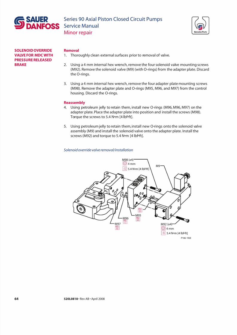
7/28/2019 Sauer90-ServiceManual.pdf
http://slidepdf.com/reader/full/sauer90-servicemanualpdf 64/72
64 520L0818 • Rev AB • April 2008
Series 90 Axial Piston Closed Circuit Pumps
Service Manual
Minor repair
Rl
1. Thoroughly clean external surfaces prior to removal of valve.
2. Using a 4 mm internal hex wrench, remove the four solenoid valve mounting screws
(M92). Remove the solenoid valve (M9) (with O-rings) from the adapter plate. Discard
the O-rings.
3. Using a 4 mm internal hex wrench, remove the four adapter plate mounting screws
(M98). Remove the adapter plate and O-rings (M95, M96, and M97) from the control
housing. Discard the O-rings.
Rl
4. Using petroleum jelly to retain them, install new O-rings (M96, M96, M97) on the
adapter plate. Place the adapter plate into position and install the screws (M98).
Torque the screws to 5.4 N•m [4 lbf•ft].
5. Using petroleum jelly to retain them, install new O-rings onto the solenoid valve
assembly (M9) and install the solenoid valve onto the adapter plate. Install the
screws (M92) and torque to 5.4 N•m [4 lbf•ft].
soLenoiD oveRRiDe
vaLve oR mDC witH
PRessuRe ReLeaseDbRake
P106 192E
M95M96
M97
M98 (x4)
M9
M92 (x4)
4 mm
4 mm
5.4 N•m [4 lbf•f t]
5.4 N•m [4 lbf•f t]
Solenoid override valve removal/installation
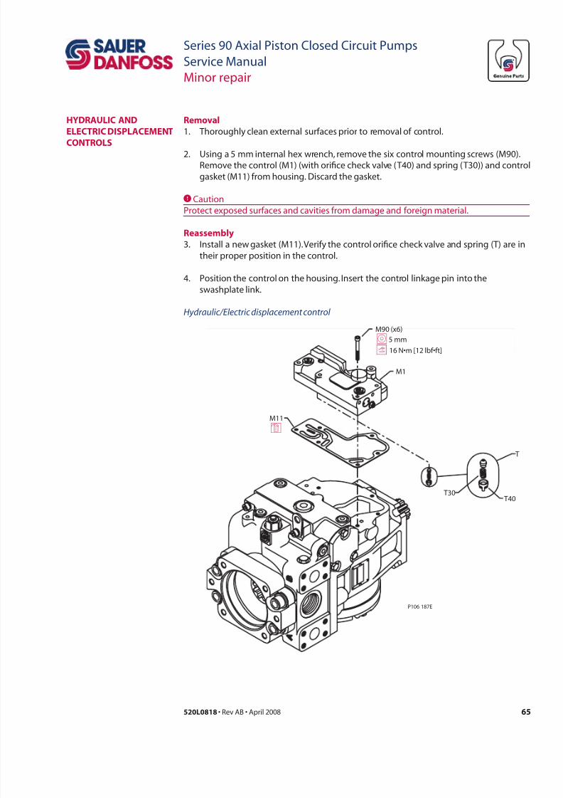
7/28/2019 Sauer90-ServiceManual.pdf
http://slidepdf.com/reader/full/sauer90-servicemanualpdf 65/72
65520L0818 • Rev AB • April 2008
Series 90 Axial Piston Closed Circuit Pumps
Service Manual
Minor repair
Rl
1. Thoroughly clean external surfaces prior to removal of control.
2. Using a 5 mm internal hex wrench, remove the six control mounting screws (M90).
Remove the control (M1) (with orice check valve (T40) and spring (T30)) and control
gasket (M11) from housing. Discard the gasket.
CCaution
Protect exposed surfaces and cavities from damage and foreign material.
Rl
3. Install a new gasket (M11). Verify the control orice check valve and spring (T) are in
their proper position in the control.
4. Position the control on the housing. Insert the control linkage pin into theswashplate link.
HyDRauLiC anD
eLeCtRiC DisPLaCement
ContRoLs
P106 187E
T
T30 T40
M90 (x6)
M1
M11d
I5 mm
16 N•m [12 lbf•ft]
Hydraulic/Electric displacement control

7/28/2019 Sauer90-ServiceManual.pdf
http://slidepdf.com/reader/full/sauer90-servicemanualpdf 66/72
66 520L0818 • Rev AB • April 2008
Series 90 Axial Piston Closed Circuit Pumps
Service Manual
Minor repair
Rl1. Thoroughly clean external surfaces of control.
2. Using a 4 mm internal hex wrench, remove the four screws (M98) and remove the
PCP (M9).
ipc
3. Check surfaces for nicks or damage. Clean internal screens.
Rl
4. Install new O-rings (M96 and M97) in PCP Housing. Place PCP against EDC housing
and install the screws (M98). Torque to 5.4 N•m [4 lbf•ft].
Do not remove black plastic cover from the aluminum plate. This is not a serviceable item
and will void the product warranty.
PRessuRe ContRoLPiLot (PCP) oR
eLeCtRiC DisPLaCement
5. With the control in position, move control assembly left and right to check
engagement of pin in the link. Proper engagement is indicated by an increasingresistance as the control is moved away from center position. Non-engagement of
pin is indicated by lack of spring force. In case of non-engagement, remove control
and repeat the above procedure.
6. Align the control gasket and install the screws. Torque the screws to 16 N•m
[12 lbf•ft].
Install a sealing washer under the head of any mounting screws that are installed into
through holes in the housing.
P106 194E
M97
M96 (x3)
M90 (x6)
M9
5 mm
M98 (x4)
4 mm
Seal washer
location
(42, 180, 250 cc)
16 N•m [12 lbf•ft]
5.4 N•m [4 lbf•f t]
PCP removal/installation
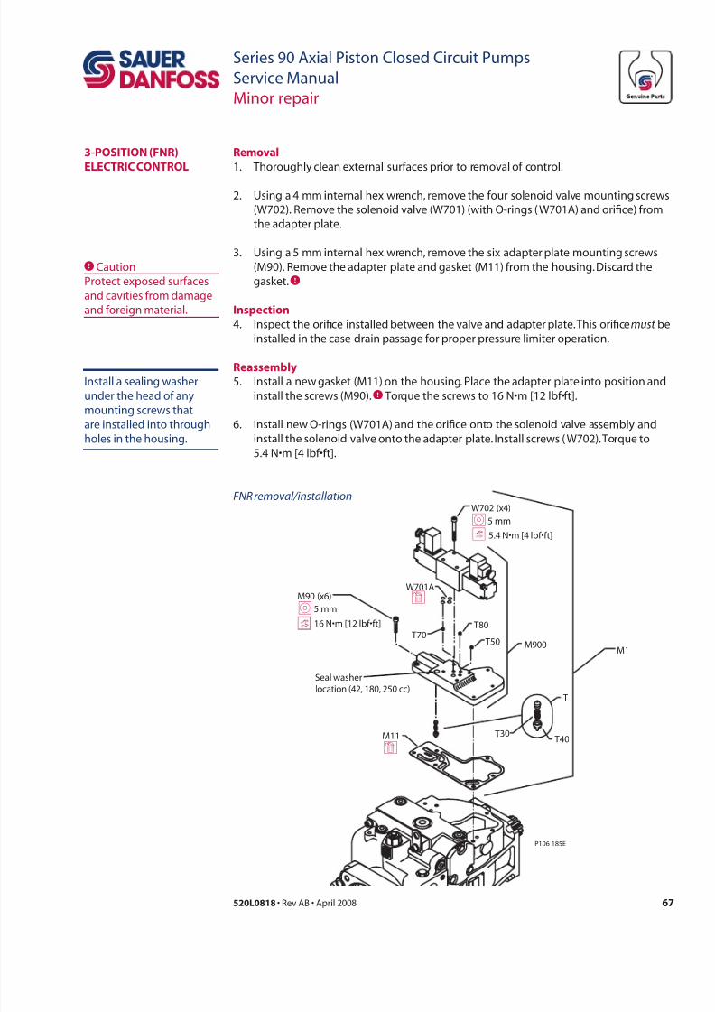
7/28/2019 Sauer90-ServiceManual.pdf
http://slidepdf.com/reader/full/sauer90-servicemanualpdf 67/72
67520L0818 • Rev AB • April 2008
Series 90 Axial Piston Closed Circuit Pumps
Service Manual
Minor repair
P106 185E
M11
M90 (x6)
T80 T70
T50
T
T30 T40
W701A
M900M1
dI5 mm
d
W702 (x4)
I5 mm
Seal washer
location (42, 180, 250 cc)
16 N•m [12 lbf•ft]
5.4 N•m [4 lbf•ft]
FNR removal/installation
Rl
1. Thoroughly clean external surfaces prior to removal of control.
2. Using a 4 mm internal hex wrench, remove the four solenoid valve mounting screws
(W702). Remove the solenoid valve (W701) (with O-rings ( W701A) and orice) from
the adapter plate.
3. Using a 5 mm internal hex wrench, remove the six adapter plate mounting screws
(M90). Remove the adapter plate and gasket (M11) from the housing. Discard the
gasket.C
ipc
4. Inspect the orice installed between the valve and adapter plate. This orice must be
installed in the case drain passage for proper pressure limiter operation.
Rl
5. Install a new gasket (M11) on the housing. Place the adapter plate into position and
install the screws (M90).C Torque the screws to 16 N•m [12 lbf•ft].
6. Install new O-rings (W701A) and the orice onto the solenoid valve assembly and
install the solenoid valve onto the adapter plate. Install screws ( W702). Torque to
5.4 N•m [4 lbf•ft].
3-Position (nR)
eLeCtRiC ContRoL
CCaution
Protect exposed surfaces
and cavities from damage
and foreign material.
Install a sealing washer
under the head of any
mounting screws that
are installed into through
holes in the housing.

7/28/2019 Sauer90-ServiceManual.pdf
http://slidepdf.com/reader/full/sauer90-servicemanualpdf 68/72
68 520L0818 • Rev AB • April 2008
Series 90 Axial Piston Closed Circuit Pumps
Service Manual
Minor repair
Rl
1. Loosen the lock nut using a 11/16 in hex wrench.
2. Unscrew the speed sensor (B83) from the pump housing. Remove and discard the
O-ring (B83A).
Rl
3. Install a new O-ring before reinstalling the sensor.
4. Reinstall the speed sensor (with lock nut and O-ring) into the housing. Adjust the
gap between the sensor and the magnetic speed ring as instructed in Speed sensor
adjustment (page 46) and torque the sensor lock nut to 13 N•m [10 lbf•ft].
5. If a speed sensor is not installed, use a 1/4 in internal hex wrench to torque the
housing plug (B83) to 40 N•m [30 lbf•ft].
sPeeD sensoR
Typical location o speed sensor
E101 095E
B83 O-ring plug
B83
B83A
B83A
40 N•m [30 lbf•ft]
40 N•m [30 lbf•ft]
DisPLaCement
ContRoL iLteR
sCReens
If the pump is equipped with control
lter screens in the pump housing (late
production), press them into position(with the rounded edge of the lter
screens facing the control) until they are
ush to 2.0 mm [0.08 inch] below the
surface of the housing.
P106 690E
B90
Filter screen installation
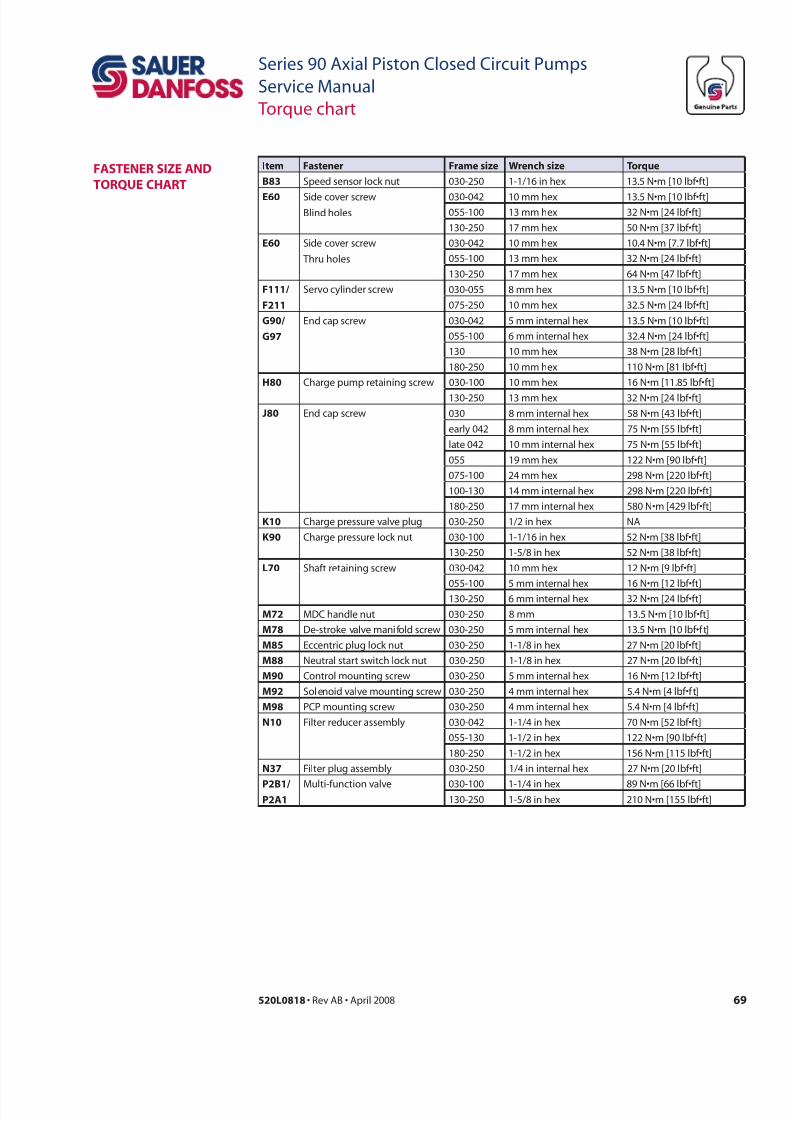
7/28/2019 Sauer90-ServiceManual.pdf
http://slidepdf.com/reader/full/sauer90-servicemanualpdf 69/72
69520L0818 • Rev AB • April 2008
Series 90 Axial Piston Closed Circuit Pumps
Service Manual
Torque chart
asteneR size anD
toRque CHaRt
i r r wrch tr
b83 Speed sensor lock nut 030-250 1-1/16 in hex 13.5 N•m [10 lbf•ft]
e60 Side cover screwBlind holes
030-042 10 mm hex 13.5 N•m [10 lbf•ft]055-100 13 mm hex 32 N•m [24 lbf•ft]
130-250 17 mm hex 50 N•m [37 lbf•ft]
e60 Side cover screw
Thru holes
030-042 10 mm hex 10.4 N•m [7.7 lbf•ft]
055-100 13 mm hex 32 N•m [24 lbf•ft]
130-250 17 mm hex 64 N•m [47 lbf•ft]
F111/
211
Servo cylinder screw 030-055 8 mm hex 13.5 N•m [10 lbf•ft]
075-250 10 mm hex 32.5 N•m [24 lbf•ft]
G90/
g97
End cap screw 030-042 5 mm internal hex 13.5 N•m [10 lbf•ft]
055-100 6 mm internal hex 32.4 N•m [24 lbf•ft]
130 10 mm hex 38 N•m [28 lbf•ft]
180-250 10 mm hex 110 N•m [81 lbf•ft]
H80 Charge pump retaining screw 030-100 10 mm hex 16 N•m [11.85 lbf•ft]
130-250 13 mm hex 32 N•m [24 lbf•ft]
j80 End cap screw 030 8 mm internal hex 58 N•m [43 lbf•ft]
early 042 8 mm internal hex 75 N•m [55 lbf•ft]
late 042 10 mm internal hex 75 N•m [55 lbf•ft]
055 19 mm hex 122 N•m [90 lbf•ft]
075-100 24 mm hex 298 N•m [220 lbf•ft]
100-130 14 mm internal hex 298 N•m [220 lbf•ft]
180-250 17 mm internal hex 580 N•m [429 lbf•ft]
k10 Charge pressure valve plug 030-250 1/2 in hex NA
k90 Charge pressure lock nut 030-100 1-1/16 in hex 52 N•m [38 lbf•ft]
130-250 1-5/8 in hex 52 N•m [38 lbf•ft]
L70 Shaft retaining screw 030-042 10 mm hex 12 N•m [9 lbf•ft]
055-100 5 mm internal hex 16 N•m [12 lbf•ft]
130-250 6 mm internal hex 32 N•m [24 lbf•ft]
m72 MDC handle nut 030-250 8 mm 13.5 N•m [10 lbf•ft]
m78 De-stroke valve manifold screw 030-250 5 mm internal hex 13.5 N•m [10 lbf•f t]
m85 Eccentric plug lock nut 030-250 1-1/8 in hex 27 N•m [20 lbf•ft]
m88 Neutral start switch lock nut 030-250 1-1/8 in hex 27 N•m [20 lbf•ft]
m90 Control mounting screw 030-250 5 mm internal hex 16 N•m [12 lbf•ft]
m92 Solenoid valve mounting screw 030-250 4 mm internal hex 5.4 N•m [4 lbf•f t]
m98 PCP mounting screw 030-250 4 mm internal hex 5.4 N•m [4 lbf•ft]
n10 Filter reducer assembly 030-042 1-1/4 in hex 70 N•m [52 lbf•ft]
055-130 1-1/2 in hex 122 N•m [90 lbf•ft]
180-250 1-1/2 in hex 156 N•m [115 lbf•ft]
n37 Filter plug assembly 030-250 1/4 in internal hex 27 N•m [20 lbf•ft]
P2B1/P2a1
Multi-function valve 030-100 1-1/4 in hex 89 N•m [66 lbf•ft]130-250 1-5/8 in hex 210 N•m [155 lbf•ft]
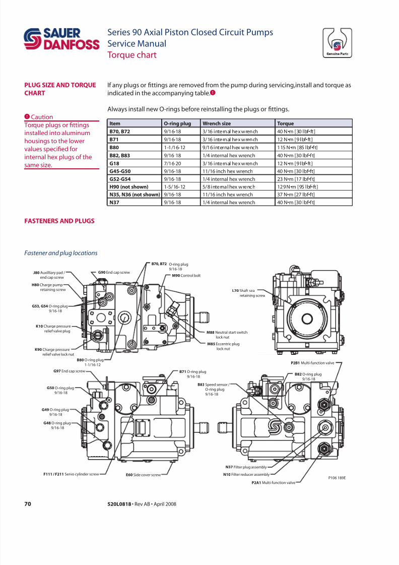
7/28/2019 Sauer90-ServiceManual.pdf
http://slidepdf.com/reader/full/sauer90-servicemanualpdf 70/72
70 520L0818 • Rev AB • April 2008
Series 90 Axial Piston Closed Circuit Pumps
Service Manual
Torque chart
If any plugs or ttings are removed from the pump during servicing,install and torque as
indicated in the accompanying table.C Always install new O-rings before reinstalling the plugs or ttings.
CCaution
Torque plugs or ttings
installed into aluminum
housings to the lower
values specied for
internal hex plugs of the
same size.
i o-r pl wrch tr
b70, b72 9/16-18 3/16 internal hex wrench 40 N•m [30 lbf•ft]
b71 9/16-18 3/16 internal hex wrench 12 N•m [9 lbf•ft]
b80 1-1/16-12 9/16 internal hex wrench 115 N•m [85 lbf•ft]
b82, b83 9/16-18 1/4 internal hex wrench 40 N•m [30 lbf•f t]
g18 7/16-20 3/16 internal hex wrench 12 N•m [9 lbf•ft]
g45-g50 9/16-18 11/16 inch hex wrench 40 N•m [30 lbf•ft]
g52-g54 9/16-18 1/4 internal hex wrench 23 N•m [17 lbf•f t]
H90 ( h) 1-5/16-12 5/8 internal hex wrench 129 N•m [95 lbf•ft]
n35, n36 ( h) 9/16-18 11/16 inch hex wrench 37 N•m [27 lbf•ft]
n37 9/16-18 1/4 internal hex wrench 40 N•m [30 lbf•f t]
PLug size anD toRque
CHaRt
Fastener and plug locations
O-ring plug
9/16-18
B82 O-ring plug
9/16-18
N10 Filter reducer assembly
B83 Speed sensor /
O-ring plug
9/16-18
P106 189E
P2A1 Multi-function valve
M88 Neutral start switch
lock nut
P2B1 Multi-function valve
K90 Charge pressure
relief valve lock nut
N37 Filter plug assembly
G97 End cap screw
M90 Control bolt
H80 Charge pump
retaining screw
J80 Auxilliary pad /
end cap screw
F111 / F211 Servo cylinder screw
G90 End cap screw
E60 Side cover screw
K10 Charge pressure
relief valve plug
L70 Shaft seal
retaining screw
M85 Eccentric plug
lock nut
B70, B72
G50 O-ring plug
9/16-18
G49 O-ring plug
9/16-18
G48 O-ring plug
9/16-18
G53, G54 O-ring plug
9/16-18
B80 O-ring plug
1-1/16-12
B71 O-ring plug
9/16-18
asteneRs anD PLugs
7/28/2019 Sauer90-ServiceManual.pdf
http://slidepdf.com/reader/full/sauer90-servicemanualpdf 71/72
71520L0818 • Rev AB • April 2008
Series 90 Axial Piston Closed Circuit Pumps
Service Manual
Notes
7/28/2019 Sauer90-ServiceManual.pdf
http://slidepdf.com/reader/full/sauer90-servicemanualpdf 72/72
sr-D ml Pr d Crl s
– mr Ldr wrldd
Sauer-Danfoss is a comprehensive supplier providing complete
systems to the global mobile market.
Sauer-Danfoss serves markets such as agriculture, construction, road
building, material handling, municipal, forestry, turf care, and many
others.
We offer our customers optimum solutions for their needs and
develop new products and systems in close cooperation and
partnership with them.
Sauer-Danfoss specializes in integrating a full range of system
components to provide vehicle designers with the most advanced
total system design.
Sauer-Danfoss provides comprehensive worldwide service for its
products through an extensive network of Global Service Partners
strategically located in all parts of the world.
ouR PRoDuCts
Hydrostatic transmissions
Hydraulic power steering
Electric power steering
Electrohydraulic power steering
Closed and open circuit axial pistonpumps and motors
Gear pumps and motors
Bent axis motors
Orbital motors
Transit mixer drives
Planetary compact gears
Proportional valves
Directional spool valves
Cartridge valves
Hydraulic integrated circuits
Hydrostatic transaxles
Integrated systems
Fan drive systems
Electrohydraulics
Microcontrollers and software
Electric motors and inverters
Joysticks and control handlesDisplays
Local address:
Sauer-Danfoss (US) Company2800 East 13th Street
Ames, IA 50010, USA
Sauer-Danfoss ApSDK-6430 Nordborg, Denmark
Phone: +45 7488 4444