Embed Size (px)
Citation preview
I E16x346 Rev:00 23.01.2009 Page 1 of 61
Postfach 1106, D71301 WaiblingenEsslinger Str. 26, WN-Hegnach Tel.: 07151/956230 Fax: 07151/956250 E-Mail: [email protected] Internet: www.braun-tacho.de ualität zertifiziert nach ISO 9001 Q
Channel A Channel B Channel C
Description
Trip-System E16x346 for Overspeed Protection
and with Voters for external Trip Release Conditions
P
E
Generator E1697
1 2 3 4
Channel A
Auto-Test
Channel B Channel C
P
E
Monitor E1667
1 2 3 4
Trip
SP3RPM
P
E
Monitor E1667
1234
Trip
SP3RPM
P
E
Monitor E1667
1 2 3 4
Trip
SP3 RPM
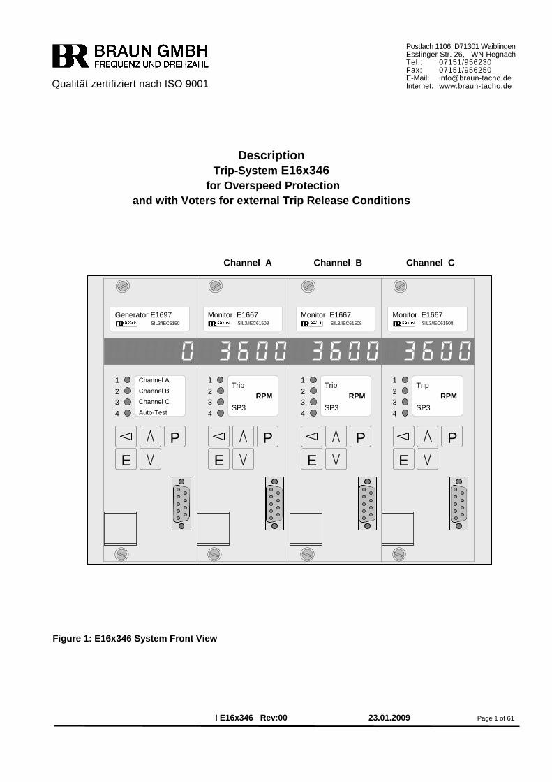
SIL3/IEC6150 SIL3/IEC61508 SIL3/IEC61508SIL3/IEC61508 Figure 1: E16x346 System Front View
Contents Page 1 General Informations ..................................................................................................4 1.1 System Applications .......................................................................................................4 1.2 Key Features ...................................................................................................................4 1.3 Ordering Key ...................................................................................................................5 2 System Structure and I/Os ...................................................................................... 5 2.1 System Structure ...............................................................................................................5 2.1.1 Speed Sensors .................................................................................................................5 2.1.2 System Components............................................................................................................5 2.1.3 System Design.....................................................................................................................5 2.1.4 System Structure Diagrams ..............................................................................................6,7 2.1.5 System Wiring Diagrams...................................................................................................8,9 2.2 System Inputs ..................................................................................................................10 2.2.1 Speed Signal Inputs...........................................................................................................10 2.2.2 Direction Signal Inputs .......................................................................................................10 2.2.3 Input Reset of Alarms ........................................................................................................10 2.2.4 Input Block Test .................................................................................................................10 2.2.5 Input Start Auto-Test..........................................................................................................10 2.2.6 Inputs Test I, Test II, Test III ..............................................................................................10 2.2.7 Inputs Starter (Override of SP2).........................................................................................10 2.2.8 Inputs 2nd Value SP1..........................................................................................................10 2.2.9 Inputs Feedback from Solenoid Valve Block......................................................................11 2.2.10 Inputs for Voter 1 .............................................................................................................11 2.2.11 Inputs for Voter 2 … 6 ......................................................................................................11 2.3 System Outputs ...............................................................................................................12 2.3.1 Outputs Alarm System Fault 1 and System Fault 2 ...........................................................12 2.3.2 Outputs Sensor Signal Repeater .......................................................................................12 2.3.3 Outputs Channel Warning Alarm .......................................................................................12 2.3.4 Outputs Speed Alarm SP3.................................................................................................12 2.3.5 Analog Output ....................................................................................................................12 2.3.6 Direction Alarm Outputs.....................................................................................................13 2.3.7 Logic Output Speed Trip ....................................................................................................13 2.3.8 Output Trip-Circuit IV ........................................................................................................13 2.3.9 Outputs Trip-Circuits I, II, III ..............................................................................................13 2.3.10 Logic Outputs LO1 through LO6 .......................................................................................13 2.4 Power Supply ...................................................................................................................13
I E16E346 Rev:00 Page 2 of 61
3 Technical Specifications ............................................................................................14 3.1 Technical Data of Inputs ..............................................................................................14 3.1.1 Technical Data of Speed Signal Inputs ...........................................................................14 3.1.2 Technical Data of Direction Signal Inputs .......................................................................14 3.1.3 Technical Data of Logic Signal Inputs ............................................................................14 3.1.4 Technical Data of Logic Signal Inputs for Voter 1 ...........................................................14 3.2 Technical Data of Outputs ........................................................................................15 3.2.1 Technical Data of Speed Signal Repeater Outputs ..........................................................15 3.2.2 Technical Data of Analog Outputs ..................................................................................15 3.2.3 Technical Data of Opto-Relay Outputs .............................................................................15 3.2.4 Technical Data of Logic Outputs ......................................................................................15 3.2.5 Technical Data of Trip-Circuit IV ....................................................................................15 3.2.6 Technical Data of Trip-Circuits I, II, III ..............................................................................15 3.4 Technical Data of Power Supply ....................................................................................16 3.5 Installation Conditions ....................................................................................................16 3.5 Protection Grade..............................................................................................................16 3.6 Connectors .......................................................................................................................16 3.7 Conformity to Standards .................................................................................................16 3.8 Dimensions of E16A346 ..................................................................................................17 3.9 Dimensions of E16E346 ..................................................................................................18 4 Description of Monitor E1667 .........................................................................................23 4.1 Display and Frontside Operational Elements ...............................................................23 4.1.1 Front View of Monitor E1667 ............................................................................................23 4.1.2 Display during Test Procedures ......................................................................................23 4.1.3 Values accessible during normal operation ....................................................................23 4.1.4 Special Display Mode 1 ...................................................................................................24 4.1.5 Special Display Mode 2 ...................................................................................................24 4.1.6 Frontside Reset of Alarms and Error Codes ...................................................................24 4.1.7 Data Interface .................................................................................................................24 4.2 Functions of Monitor E1667 ...........................................................................................25 4.2.1 Speed Measurement ........................................................................................................25 4.2.2 Functions for Overspeed Protection ..................................................................................25 4.2.3 Functions for External Trip by Voters ...............................................................................25 4.2.4 Selftest of Monitor E1667 ................................................................................................25 5 Description of Testgenerator E1697...............................................................................26 5.1 Display and Frontside Operational Elements ...............................................................26 5.1.1 Front View of Testgenerator E1697 .................................................................................26 5.1.2 Display during Test Procedures ......................................................................................26 5.1.3 Values accessible during normal operation ....................................................................26 5.1.4 Frontside Reset of Alarms and Error Codes ...................................................................27 5.1.5 Frontside Start of a Monitor-Test Sequence ....................................................................27 5.1.6 Frontside Start of a Trip-Line-Test Sequence ....................................................................27 5.1.7 Data Interface .................................................................................................................27 5.2 Functions of Testgenerator E1697 ................................................................................28 5.2.1 Test of Feedback Signals ................................................................................................28 5.2.2 Monitor-Test Sequence .....................................................................................................28 5.2.3 Trip-Line-Test Sequence (Test of 2oo3 solenoid valve block) .........................................28 5.2.4 Crosscheck between CPUs of Testgenerator .................................................................28
I E16E346 Rev:00 Page 3 of 61
5.2.5 Selftest of CPUS of Testgenerator ..................................................................................29 6 Programming of the Modules .........................................................................................30 6.1 Programming of the Modules via Front Keyboard........................................................30 6.2 Programming of the Modules via PROFIBUS-Interface ................................................31 6.3 Programming of the Modules via RS232-Interface .......................................................31 7 Parameters of Monitor E1667..........................................................................................32 7.1 Summary of Parameters of Monitor E1667 ...............................................................32-34 7.2 Description of Parameters and Adjustments of MonitorE1667...............................35-55 8 Parameters of Testgenerator E1697 ...............................................................................56 8.1 Summary of Parameters of Testgenerator E1697 .........................................................56 8.2 Description of Parameters and Adjustments of Testgenerator E1697 ...................57-61
I E16E346 Rev:00 Page 4 of 61
1 General Informations
1.1 System Applications Protection of rotating machinery such as turbines, expanders, compressors and motors with safety requirements SIL3/IEC61508 and/or API 670 versus Overspeed and other Critical Con-ditions. Trip is released by shut down of the Trip Circuits (Trip-Lines) for the 2oo3 Solenoid Valve Block if:
• 2oo3 monitors detect Overspeed condition • 2oo3 sensor signals are detected as faulty by monitors • 2oo3 monitors detect External Trip-Condition
1.2 Key Features of System E16x346 Trip Release Function is SIL3/IEC61508 compliant as stand alone unit (without external testing by DCS or by operator). Total Response Time to Trip Condition : < 15 milliseconds Maximum Safety at Maximum Availability by :
• TMR (Triple Modular Redundancy) with three monitors E1667. • Triple speed measurement and evaluation by each monitor . • Variable overspeed setpoint depending on acceleration. • Monitoring versus lowspeed as protection versus incorrect mounting of speed sen-
sors. • Permanent monitoring of speed sensors. • Evaluation of external Trip-Condition signals by voters in each monitor. Response to
signals selectable for each voter individually (1oo2, 2oo3, low/high= trip, response time).
• Permanent monitoring of monitors by testgenerator with cyclic full automatic tests or externally triggered tests..
• Permanent monitoring of 2oo3 Solenoid Valve Block by testgenerator with cyclic full automatic or externally triggered tests.
• Each Trip Line (trip circuit) in 2oo3 technique. • Trip Lines I, II, III, IV formed by safety relays with force guided contact sets. • Trip-Line-Monitoring with Trip-Lock Function (selectable):
The outputs of the Trip Lines to the 2oo3 Solenoid Valve Block are permanently monitored. If the Trip-Lock Function is engaged, a trip condition is detected and locked if 2oo3 trip lines are in trip condition.
Remote test of solenoid valve block by test signals from DCS possible. Display in each module for measured values and diagnostics. Alarm outputs via opto relays to DCS. Free extra setpoint from each monitor. Up to 6 speed setpoints with 2oo3 logic outputs (if voters are not required). Sensor signal repeater outputs, free floating and push/pull. Parameters may be set by front keys or by RS232-Interface or by Profibus-Interface.
I E16E346 Rev:00 Page 5 of 61
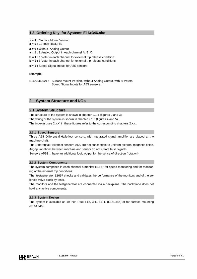
1.3 Ordering Key for Systems E16x346.abc x = A : Surface Mount Version x = E : 19-Inch Rack File
a = 0 : without Analog Output a = 1 : 1 Analog Output in each channel A, B, C
b = 1 : 1 Voter in each channel for external trip release condition b = 2 : 6 Voter in each channel for external trip release conditions
c = 1 : Speed Signal Inputs for A5S sensors
Example: E16A346.021 : Surface Mount Version, without Analog Output, with 6 Voters, Speed Signal Inputs for A5S sensors
2 System Structure and I/Os
2.1 System Structure The structure of the system is shown in chapter 2.1.4 (figures 2 and 3). The wiring of the system is shown in chapter 2.1.5 (figures 4 and 5). The indexes „see 2.x.x“ in these figures refer to the corresponding chapters 2.x.x..
2.1.1 Speed Sensors Three A5S Differential-Halleffect sensors, with integrated signal amplifier are placed at the machine shaft. The Differential Halleffect sensors A5S are not susceptible to uniform external magnetic fields. Airgap variations between machine and sensor do not create false signals. Sensors A5S3… have an additional logic output for the sense of direction (rotation).
2.1.2 System Components The system comprises in each channel a monitor E1667 for speed monitoring and for monitor-ing of the external trip conditions. The testgenerator E1697 checks and validates the performance of the monitors and of the so-lenoid valve block by tests. The monitors and the testgenerator are connected via a backplane. The backplane does not hold any active components.
2.1.3 System Design The system is available as 19-Inch Rack File, 3HE 84TE (E16E346) or for surface mounting (E16A346).
I E16E346 Rev:00 Page 6 of 61
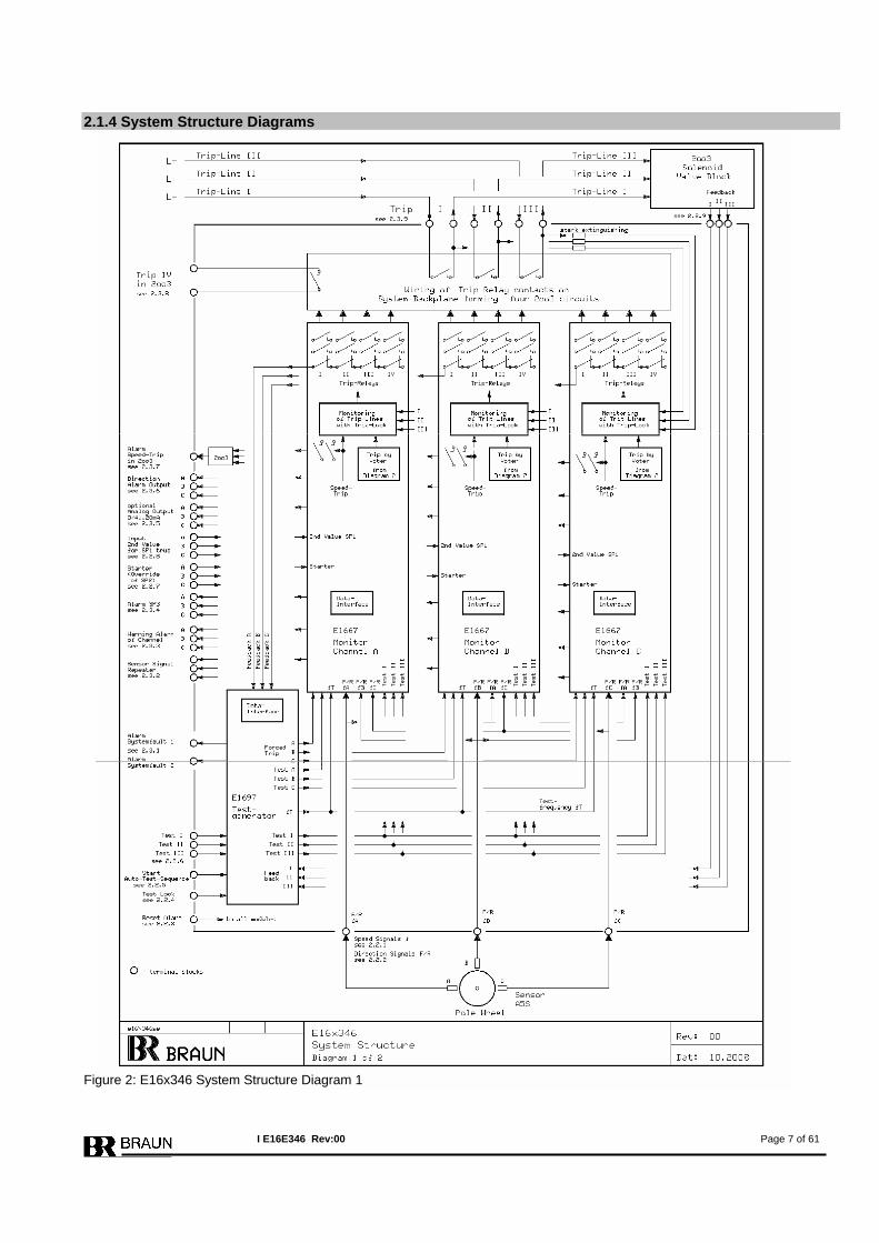
2.1.4 System Structure Diagrams Figure 2: E16x346 System Structure Diagram 1
I E16E346 Rev:00 Page 7 of 61
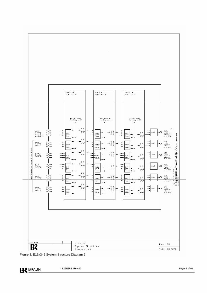
Figure 3: E16x346 System Structure Diagram 2
I E16E346 Rev:00 Page 8 of 61
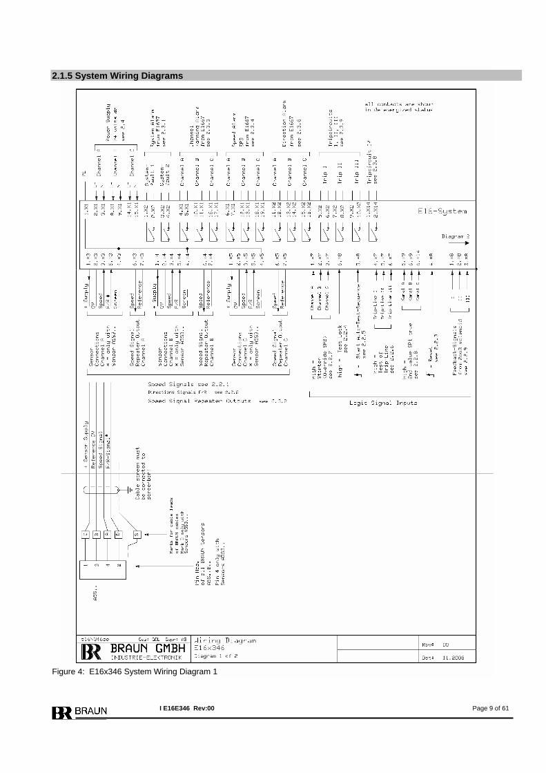
2.1.5 System Wiring Diagrams Figure 4: E16x346 System Wiring Diagram 1
I E16E346 Rev:00 Page 9 of 61
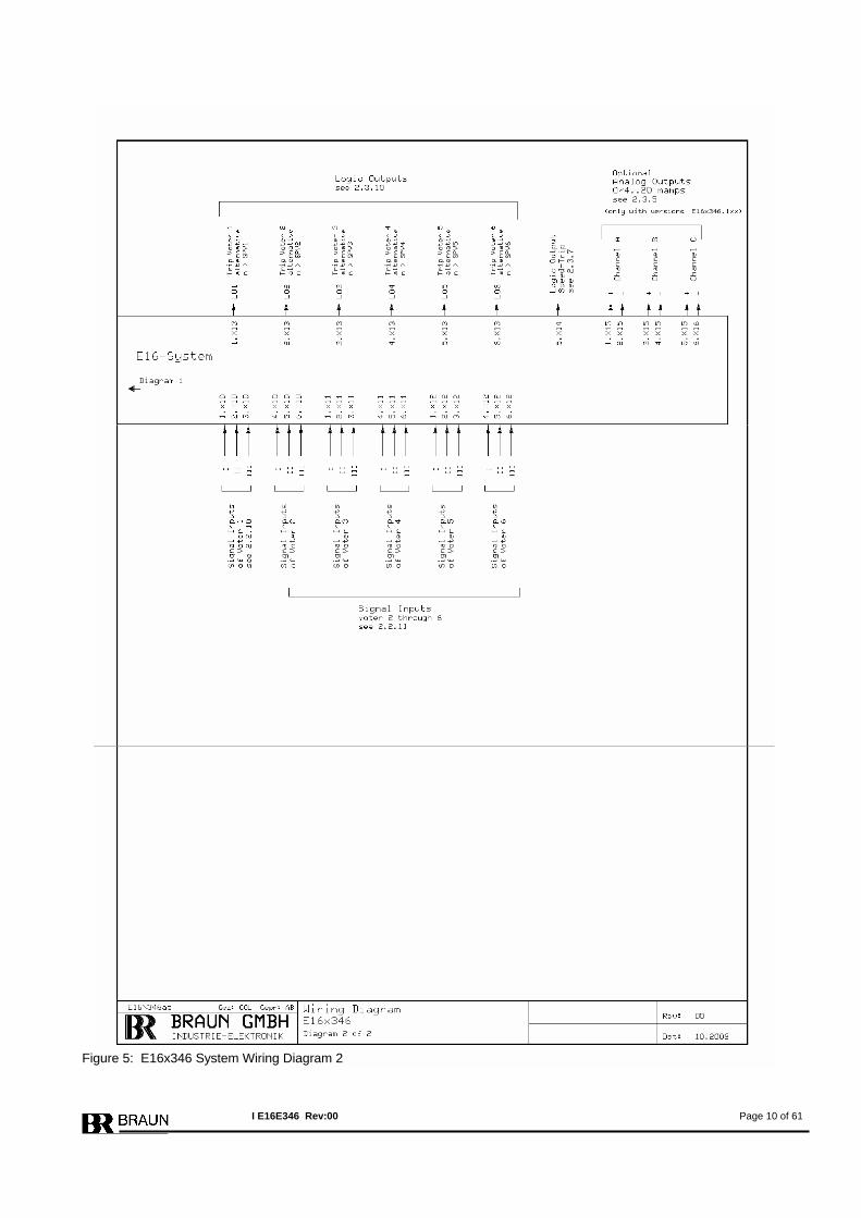
Figure 5: E16x346 System Wiring Diagram 2
I E16E346 Rev:00 Page 10 of 61
2.2 Inputs of the System
2.2.1 Speed Signal Inputs The speed signal inputs match the values of the sensors A5S. The speed signals are internally wired to all three monitors in parallel. Technical Data of inputs see 3.1.1.
2.2.2 Direction Signal Inputs (F/R = Forward/Reverse) The direction signal inputs match the values of the sensors A5S3… The direction signals are internally wired to all three monitors in parallel. Technical Data of inputs see 3.1.2.
2.2.3 Input Reset of Alarms The Reset signal is internally connected to all modules in parallel. It resets a no longer prevailing, but latched alarm or trip condition. A signal transition from low to high will reset a latched alarm. Minimum Time of Reset Signal: > 1 second Technical Data of input see 3.1.3.
2.2.4 Input Test Lock A high signal will cancel a running test and inhibit further tests as long as the signal is high. If the signal is true for more than 60 minutes, the alarms Systemfault 1 and Systemfault 2 are released. Technical Data of input see 3.1.3.
2.2.5 Input Start Auto-Test-Sequence A signal transition from low to high will start an Auto-Test-Sequence. First the test (if se-lected, see step P03.01 of E1697) of the trip lines for the solenoid valve block is per-formed, two minutes later the test of the monitors is performed.
Technical Data of input see 3.1.3.
2.2.6 Inputs Test I , Test II, Test III The inputs Test I, II, III are enabled, if the testgenerator E1697 is programmed to external solenoid valve test (see step P03.01 of E1697). If the input is high, the corresponding Trip-Line will switch to trip condition. The inputs are inhibited versus each other. If two or three inputs are high at the same time, no test is performed. Technical Data of inputs see 3.1.3.
2.2.7 Inputs Starter (Override of SP2) Each monitor has one input for the starter condition. As long as the input is high, the starter condition is true. During starter condition the monitoring versus lowspeed (SP2) is disabled. Technical Data of inputs see 3.1.3.
2.2.8 Inputs 2nd Value SP1 Each monitor has one input to select a 2nd value for SP1 (trip setpoint). As long as the input is high, value SP1L (see step P03.03 of E1667) is true. With open input (low), value SP1H (see P03.00 of E1667) is true. Technical Data of inputs see 3.1.3.
I E16E346 Rev:00 Page 11 of 61
2.2.9 Inputs Feedback from Solenoid Valve Block The feedback inputs are connected to the testgenerator E1697. The inputs are only monitored if the auto test mode for solenoid valve block is selected (see step P03.01 of E1697). The signal truth level (high or low = trip condition) is selectable (see step P03.03 of E1697). Technical Data of input see 3.1.3.
2.2.10 Inputs for Voter 1 The input signals for Voter 1 are internally connected to all monitors in parallel. The input load of Voter 1 meets the requirements for the redundant outputs of a failsafe PLC (load > 45 mamps per input). The signal truth level (high or low = trip condition), the voting principle (1oo2, 2oo2, 2oo3) and the response time is selectable. Configuration of the voter is done in steps P10.xx of E1667. Technical Data of inputs for Voter 1 see 3.1.4.
2.2.11 Inputs for Voters 2 … 6 The input signals for Voters 2 … 6 are internally connected to all monitors in parallel. The signal truth level (high or low = trip condition), the voting principle (1oo2, 2oo2, 2oo3) and the response time is selectable for each voter individually. Configuration of voters is done in steps P11.xx to P15.xx of E1667. Technical Data of inputs for Voter 2 … 6 see 3.1.3. Note: Systems E16x346.x1x do not have inputs for Voters 2 … 6 .
I E16E346 Rev:00 Page 12 of 61
2.3 Outputs of the System
2.3.1 Outputs Systemfault 1 and Systemfault 2 The alarms Systemfault 1 and Systemfault 2 from testgenerator E1697 are released if:
• a channel does not show correct response • a channel releases a sensor fault alarm • the feedback signals from the solenoid valve block do not show correct response (if
monitored) • one or more channels signalize a nonconformity of their voter inputs
If the alarms Systemfault 1 and Systemfault 2 do not have the same status, the testgenerator E1697 itself has a malfunction. Technical Data of outputs see 3.2.3.
2.3.2 Speed Signal Repeater Outputs Each channel repeats the speed signal of its main sensor (channel A repeats sensor A) to the periphery. Technical Data of outputs see 3.2.1.
2.3.3 Outputs Channel Warning Alarm The channel warning alarm (for each channel individually) is released if :
• Channel releases trip (due to overspeed resp. voter), if selected. Selection in step P02.11 of E1667.
• Deviation of its own sensors versus both sensors of neighbour channels, if moni-tored.
Selection in steps P02.07 through P02.09 of E1667. • Measured speed lower than SP2 (after starter condition), if monitored.
Selection in step P02.06 of E1667. • Sensor Circuit Fault, if monitored.
Selections in steps P02.04 and P02.05 of E1667. Note: The channel warning alarm is not released, if the channel detects a nonconformity at its voter inputs. This status is forwarded to the testgenerator which then releases the alarms System Fault 1 and System Fault 2. Technical Data of outputs see 3.2.3.
2.3.4 Outputs Speed Alarm SP3 Each channel has a free adjustable speed alarm output SP3. Configuration of SP3 in steps P05.xx of E1667. Technical Data of outputs see 3.2.3.
2.3.5 Analog Outputs (Option) The (optional) analog outputs have a range of 0/4..20 mamps. Configuration of the analog output in steps P06.xx of E1667. Technical Data of outputs see 3.2.2.
I E16E346 Rev:00 Page 13 of 61
2.3.6 Direction Alarm Outputs If operated with sensors A5S3… , the sense of direction is signalized. Each channel votes the direction input signals 2oo3. Each channel has a direction alarm out-put. Technical Data of outputs see 3.2.3.
2.3.7 Speed Trip Logic Output (2oo3 voted) Speed Trip Logic Output is released, as long as the machine is in overspeed status. Output high: no speed trip Output low: speed trip Technical Data of output see 3.2.4.
2.3.8 Output Tripcircuit IV Tripcircuit IV is a 2oo3-circuit, formed by the contacts of safety trip relays IV of channels A,B,C. Trip is released if minimum two monitors E1667 are in trip status. Tripcircuit IV is intended to signalize the trip to a DCS or PLC. Tripcircuit IV is rated SIL3/IEC61508.
2.3.9 Outputs Tripcircuit I, II, III The tripcircuits I, II, III are 2oo3-circuits formed by the contacts of safety trip relays I resp. II, resp. III of channels A,B,C. Trip is released if minimum two monitors E1667 are in trip status. Tripcircuits I, II, III are intended to supply shutdown solenoid valves. Tripcircuits I, II, III are rated SIL3/IEC61508.
2.3.10 Logic Outputs LO1 through LO6 (voted 2oo3) The logic outputs LO may be assigned to signalize a voter trip or to a speed setpoint. If assigned to Voter Trip: Output high: no trip of Voter Output low: trip of Voter If assigned to speed setpoint: Output high/low if n > SP is selectable.
2.4 Power Supply Each channel must be supplied with 24 volts dc (18..40 volts). The Test Generator E1697 is fed by an internal power rail. Technical Data see 3.3.
I E16E346 Rev:00 Page 14 of 61
3 Technical Specifications 3.1 Technical Data of Inputs 3.1.1 Technical Data of Speed Signal Inputs Maximum Input Frequency: 50 kHz Maximum Signal Voltage: 30 volts Input low at : < 3 volts Input high at : > 7 volts Impedance : approx. 5 kohms Sensor Supply: approx. 11 volts, maximum 80 mamps Inputs are free floating. 3.1.2 Technical Data of Direction Inputs Maximum Signal Voltage: 30 volts Input low at : < 3 volts Input high at : > 7 volts Impedance : approx. 22 kohms Same Reference as Speed Signal Inputs. 3.1.3 Technical Data of Binary Inputs (excluding Voter 1) Input high : 18..48 volts (nominal current at 24 volts: 6 mamps) Input low : < 3 volts or open input Reference: negative pole of power supply 3.1.4 Technical Data of Binary Inputs of Voter 1 Input high : 18..30 volts (nominal current at 24 volts: 45 mamps) Input low : < 3 volts or open input Reference: negative pole of power supply
I E16E346 Rev:00 Page 15 of 61
3.2 Technical Data of Outputs 3.2.1 Technical Data of Sensor Signal Repeater Outputs High-Level : > 20 volts with max. load, (maximum 26 volts without load) Low-Level : < 2 volts, with max. load Maximum load: 1 kohms Outputs are shortcircuit proof and free floating (also versus each other). 3.2.2 Technical Data of Analog Outputs Range: 0/4…20 mamps Resolution: 12 Bit Maximum load: 500 ohms Linearity error : < 0.1% Outputs are shortcircuit proof and free floating (also versus each other). 3.2.3 Technical Data of Opto-Relay Outputs Maximum rating: 50 volts dc / 50 mamps. Outputs are shortcircuit proof and free floating (also versus each other). 3.2.4 Technical Data of Logic Outputs The outputs are fed from the system power supply. Reference: L- (negative pole of power supply). High-Level: Power supply L+ minus 2 volts Low-Level : < 3 volts Maximum output current : 50 mamps Outputs are shortcircuit proof. 3.2.5 Technical Data of Trip-Circuit IV Maximum rating: 50 volts dc / 50 mamps. Output is not shortcircuit proof. Output is free floating. 3.2.6 Technical Data of Trip-Circuits I, II, III Maximum rating: 50 volts dc / 3 amps / 75 watts Maximum rating for DC13-applications: 24 volts / 3 amps Outputs are not shortcircuit proof (permanent currents exceeding 8 amps will destroy outputs). Impedance: 10 kohms versus L- (negative pole of power supply) For inductive type loads, external spark extinguishing means must be provided. Total response time (trip relays de-energize to trip) from trip event until trip circuits are in trip condition: < 15 milliseconds.
I E16E346 Rev:00 Page 16 of 61
3.3 Technical Data of Power Supply 3x 24 volts dc / 0.5 amps (18…40 volts) Maximum consumption of system : 20 watts
3.4 Installation Conditions Ambient temperature in operation: 0°C..+55°C Ambient temperature in storage: -20°C..+85°C Relative humidity < 75% To be installed in dry cabinets in airconditioned rooms.
3.5 Protection Grade IP20 Insulation Class I
3.6 Connectors Plug-In Cage-Clamp Connectors, type Phoenix Combicon FK-MLP1,5/…ST-3,5
3.7 Conformity to Standards SIL3/IEC61508, API 670, 2006/95/EU, EN 61010-1, 2004/108/EU, EN 61000-6-2, EN 61000-6-4
I E16E346 Rev:00 Page 17 of 61
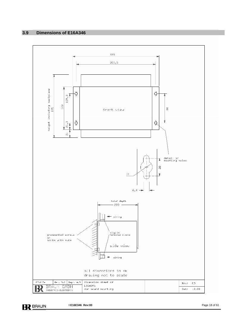
3.9 Dimensions of E16A346
I E16E346 Rev:00 Page 18 of 61
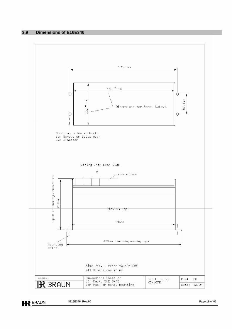
3.9 Dimensions of E16E346
I E16E346 Rev:00 Page 19 of 61

This page left blank intentionally.
I E16E346 Rev:00 Page 20 of 61

This page left blank intentionally.
I E16E346 Rev:00 Page 21 of 61

This page left blank intentionally.
I E16E346 Rev:00 Page 22 of 61
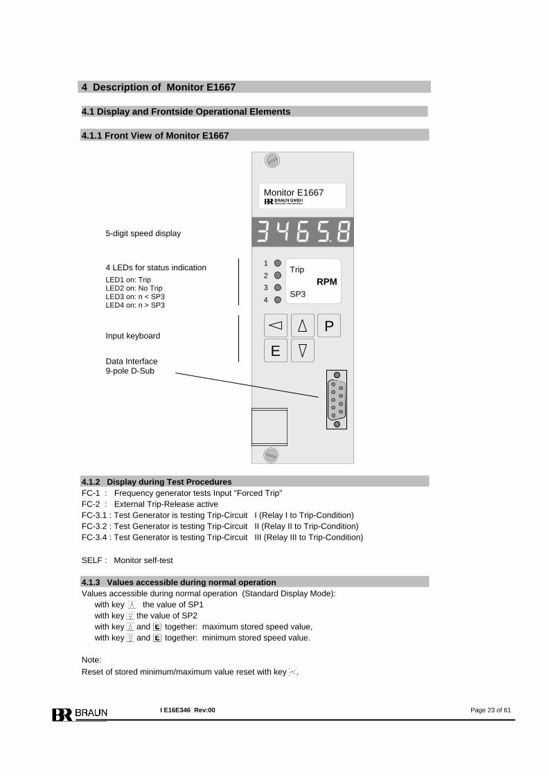
4 Description of Monitor E1667 4.1 Display and Frontside Operational Elements 4.1.1 Front View of Monitor E1667
4.1.2 Display during Test Procedures FC-1 : Frequency generator tests Input "Forced Trip" FC-2 : External Trip-Release active FC-3.1 : Test Generator is testing Trip-Circuit I (Relay I to Trip-Condition) FC-3.2 : Test Generator is testing Trip-Circuit II (Relay II to Trip-Condition) FC-3.4 : Test Generator is testing Trip-Circuit III (Relay III to Trip-Condition) SELF : Monitor self-test 4.1.3 Values accessible during normal operation Values accessible during normal operation (Standard Display Mode):
with key the value of SP1 with key the value of SP2 with key and together: maximum stored speed value, with key and together: minimum stored speed value.
Note: Reset of stored minimum/maximum value reset with key .
5-digit speed display
Input keyboard
4 LEDs for status indication
LED1 on: Trip LED2 on: No Trip LED3 on: n < SP3 LED4 on: n > SP3
P
E
Monitor E1667
1
2 3
4
Trip
SP3RPM
Data Interface 9-pole D-Sub
I E16E346 Rev:00 Page 23 of 61
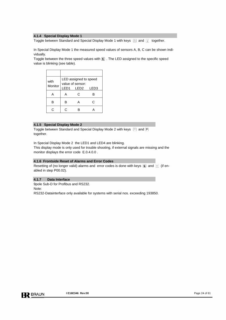
4.1.4 Special Display Mode 1 Toggle between Standard and Special Display Mode 1 with keys and together.
In Special Display Mode 1 the measured speed values of sensors A, B, C can be shown indi-vidually. Toggle between the three speed values with . The LED assigned to the specific speed value is blinking (see table).
with Monitor
LED assigned to speed value of sensor: LED1 LED2 LED3
A A C B
B B A C
C C B A
4.1.5 Special Display Mode 2 Toggle between Standard and Special Display Mode 2 with keys and together. In Special Display Mode 2 the LED1 and LED4 are blinking. This display mode is only used for trouble shooting, if external signals are missing and the monitor displays the error code E.0.4.0.0 . 4.1.6 Frontside Reset of Alarms and Error Codes Resetting of (no longer valid) alarms and error codes is done with keys and (if en-abled in step P00.02). 4.1.7 Data Interface 9pole Sub-D for Profibus and RS232. Note: RS232-Datainterface only available for systems with serial nos. exceeding 193850.
I E16E346 Rev:00 Page 24 of 61
4.2 Functions of Monitor 1667 For a detailed description of the individual functions refer to chapter 7 . 4.2.1 Speed Measurement Each monitor receives the signal from the three sensors and calculates the speed from each signal. For the further evaluation it selects (depending on parameter settings) the calculated speed value derived of its own sensor or the mean value of all three speed values. Speed calculation is done by measuring the time in between the pulses. The minimum meas-urement time is 5 milliseconds. To compensate for an imperfect gear, a predivider may be introduced to reduce the signal fre-quency to 1 pulse per revolution. 4.2.2 Functions for Overspeed Protection Overspeed protection is done by :
• Monitoring of Sensors • Monitoring versus lowspeed as protection versus incorrect mounting of speed sen-
sors. • Monitoring versus overspeed
4.2.3 Functions for External Trip by Voters Trip is released, if one of the voters detects an external trip condition. Voters may be configured as 1oo2, 2oo2, 2oo3 or 3oo3. High or low Input-Level as trip condi-tion and response time is selectable. 4.2.4 Selftest of Monitor Selftest is performed at an interval of 2 hours. Execution of Selftest is signalized on display with message SELF. Selftest of the monitors are inhibited versus each other. The Selftest routine includes
• CPU RAM-Test • CPU EEPROMTest • CPU Command-Test • CPU Register-Test • Voter Signalinput-Test
If the Selftest detects a malfunction, the monitor is set to trip-status.
I E16E346 Rev:00 Page 25 of 61
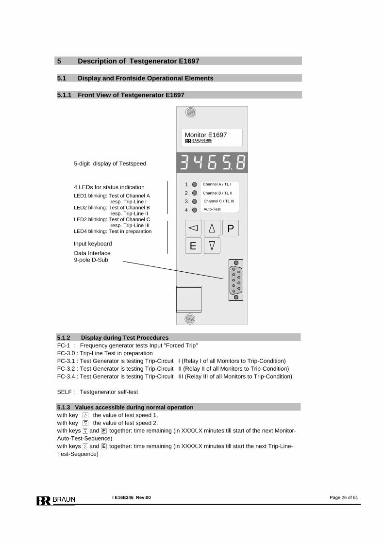
5 Description of Testgenerator E1697 5.1 Display and Frontside Operational Elements 5.1.1 Front View of Testgenerator E1697
5.1.2 Display during Test Procedures FC-1 : Frequency generator tests Input "Forced Trip" FC-3.0 : Trip-Line Test in preparation FC-3.1 : Test Generator is testing Trip-Circuit I (Relay I of all Monitors to Trip-Condition) FC-3.2 : Test Generator is testing Trip-Circuit II (Relay II of all Monitors to Trip-Condition) FC-3.4 : Test Generator is testing Trip-Circuit III (Relay III of all Monitors to Trip-Condition) SELF : Testgenerator self-test 5.1.3 Values accessible during normal operation with key the value of test speed 1, with key the value of test speed 2. with keys and together: time remaining (in XXXX.X minutes till start of the next Monitor-Auto-Test-Sequence) with keys and together: time remaining (in XXXX.X minutes till start the next Trip-Line-Test-Sequence)
5-digit display of Testspeed
Input keyboard
4 LEDs for status indication
LED1 blinking: Test of Channel A resp. Trip-Line I LED2 blinking: Test of Channel B resp. Trip-Line II LED2 blinking: Test of Channel C resp. Trip-Line III LED4 blinking: Test in preparation P
E
Monitor E1697
1
2 3
4
Channel C / TL III
Channel B / TL II
Auto-Test
Channel A / TL I
Data Interface 9-pole D-Sub
I E16E346 Rev:00 Page 26 of 61
5.1.4 Frontside Reset of Alarms and Error Codes Resetting of (no longer valid) alarms and error messages is done with key . 5.1.5 Manual Start of a Monitor-Test Sequence The test routine can be activated from the front of the test generator by pressing keys and
simultaneously. 5.1.6 Manual Start of a Trip-Line-Test Sequence The test routine can be activated from the front of the test generator by pressing keys and
simultaneously. 5.1.7 Data Interface 9pole Sub-D for Profibus and RS232. Note: RS232-Datainterface only available for systems with serial nos. exceeding 193850.
I E16E346 Rev:00 Page 27 of 61
5.2 Functions of Testgenerator 1697 For a detailed description of the individual functions refer to chapter 8 . 5.2.1 Test of Feedback Signals During normal operation the trip and alarm feedback signals of the monitors and the Trip-Lines are permanently checked. If one or more monitors or Trip-Lines are in alarm or trip status, the testgenerator releases its alarm outputs “System Fault 1” and “System Fault 2”. Monitor test and Trip-Line test is inhibited during this status.
5.2.2 Monitor-Test Sequence During the monitor test sequence each monitor is sequentially subjected to a test sequence consisting of two simulated test speeds followed by a ‚Forced Trip’ signal. The time interval of these tests is programmable.
1st Step: Each channel is sequentially provided with a testspeed 1 (n >SP1) to which the channel under test must respond with trip release. 2nd Step: Each channel is sequentially provided with a testspeed 2 (n < SP1) to which the channel under test must not respond with trip release.
3rd Step: The ‘Forced Trip’ control input of each channel is sequentially activated to which the channel under test must respond with trip release. During this step the monitor is provided with Test speed 2 (n < SP1)
In the event of an incorrect response the test will be discontinued and the testgenerator re-leases the alarms System Fault 1 and 2. 5.2.3 Trip-Line-Test Sequence (Test of 2oo3 solenoid valve block) The Testgenerator commands the monitors to put sequentially the trip relays I, II or III to trip condition. By doing so the designated Trip-Line to the solenoid valve is in trip condition. The condition of the solenoid valve is passed back to the E16 system. The testing of Trip-Line I must provide the response of Trip I. The testing of Trip-Line II must provide the response of Trip II. The testing of Trip-Line III must provide the response of Trip III. In the event of an incorrect response the test will be discontinued and the testgenerator re-leases the alarm System Fault 1 and 2. 5.2.4 Cross-check between CPUs of Testgenerator The testgenerator incorporates two redundant CPUs. Both CPUs must perform identically to release a test sequence. In case of failure of one CPU no test is released, but alarm System Fault 1 or 2 is released.
I E16E346 Rev:00 Page 28 of 61
5.2.5 Selftest of CPUs Selftest is performed after each monitor test sequence. Execution of Selftest is signalized on display with message SELF. The Selftest of both CPU routine includes
• CPU RAM-Test • CPU EEPROMTest • CPU Command-Test • CPU Register-Test
If the Selftest detects a malfunction, alarm System Fault 1 or 2 is released.
I E16E346 Rev:00 Page 29 of 61
6 Programming of the Modules
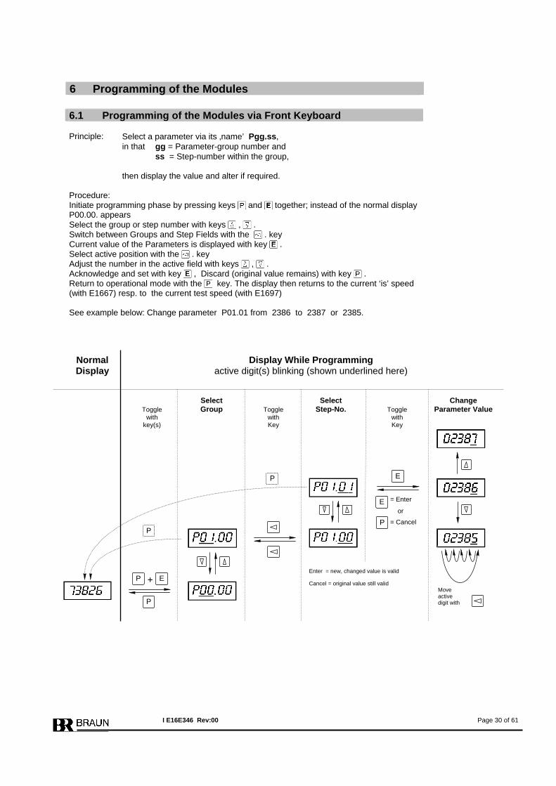
6.1 Programming of the Modules via Front Keyboard Principle:
Select a parameter via its ‚name’ Pgg.ss, in that gg = Parameter-group number and ss = Step-number within the group, then display the value and alter if required.
Procedure: Initiate programming phase by pressing keys and together; instead of the normal display P00.00. appears Select the group or step number with keys , . Switch between Groups and Step Fields with the . key Current value of the Parameters is displayed with key . Select active position with the . key Adjust the number in the active field with keys , . Acknowledge and set with key , Discard (original value remains) with key . Return to operational mode with the key. The display then returns to the current ‘is’ speed (with E1667) resp. to the current test speed (with E1697)
See example below: Change parameter P01.01 from 2386 to 2387 or 2385.
Move active digit with
Normal Display While Programming Display active digit(s) blinking (shown underlined here) Select Select Change Toggle Group Toggle Step-No. Toggle Parameter Value with with with key(s) Key Key
+
P
P E
E
E = Enter
or
= Cancel P
P
P
Cancel = original value still valid
Enter = new, changed value is valid
I E16E346 Rev:00 Page 30 of 61
6.2 Programming of the Modules via PROFIBUS-Interface Only possible for OEM with special interface-software by BRAUN. 6.3 Programming of the Modules via RS232-Interface Only possible for OEM with special interface-software. Note: RS232-Datainterface only available for systems with serial nos. exceeding 193850.
I E16E346 Rev:00 Page 31 of 61
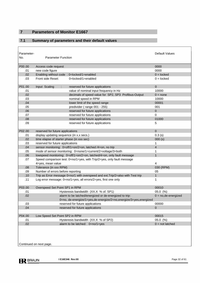
7 Parameters of Monitor E1667 7.1 Summary of parameters and their default values
Parameter- Default Values No. Parameter Function P00 .00 Access code request 0000 .01 new code figure 0000 .02 Enabling without code : 0=locked/1=enabled 0 = locked .03 Front side Reset: 0=locked/1=enabled 0 = locked P01 .00 Input Scaling : reserved for future applications 0 .01 value of nominal input frequency in Hz 10000 .02 decimals of speed value for SP2, SP3 Profibus-Output 0 = none .03 nominal speed in RPM 10000 .04 lower limit of the speed range 00001 .05 predivider ( range 001 - 255) 001 .06 reserved for future applications 0 .07 reserved for future applications 0 .08 reserved for future applications 01000 .09 reserved for future applications 5 P02 .00 reserved for future applications 0 .01 display updating sequence (in x.x secs.) 0.3 (s) .02 time elapse of starter phase (in xxx sec) 000 (s) .03 reserved for future applications 1 .04 sensor monitoring: 0=off/1=on/2=on, latched /4=on, no trip 4 .05 mode of sensor monitoring: 0=none/1=current/2=voltage/3=both 1 .06 lowspeed monitoring: 0=off/1=on/2=on, latched/4=on, only fault message 1 .07 Speed comparison test: 0=no/1=yes, with Trip/2=yes, only fault message 4=yes, mean value 4 .08 Tolerance (in xxx RPM) 030 (RPM) .09 Number of errors before reporting 05 .10 Trip as Error message 0=no/1 with overspeed and ext.Trip/2=also with Test trip 1 .11 Log error message: 0=no/1=yes, all errors/2=yes, first one only 1 P03 .00 Overspeed Set Point SP1 in RPM 00010 .01 Hysteresis bandwidth (XX.X % of. SP1) 05.0 (%) .02 alarm to be latched/energized or de-energized to trip: 0 = no,de-energized 0=no, de-energize/1=yes,de-energize/2=no,energize/3=yes,energized .03 reserved for future applications 00000 .04 reserved for future applications 0 P04 .00 Low Speed Set Point SP2 in RPM 00015 .01 Hysteresis bandwidth (XX.X % of SP2) 05.0 (%) .02 alarm to be latched: 0=no/1=yes 0 = not latched Continued on next page.
I E16E346 Rev:00 Page 32 of 61
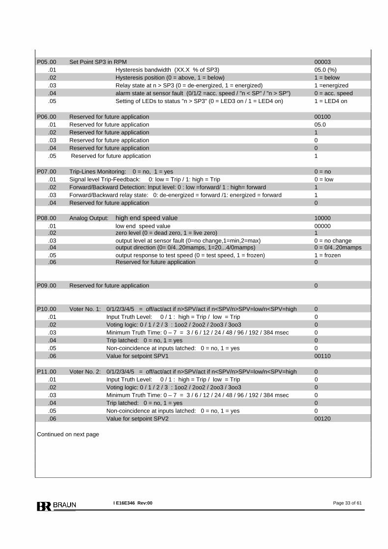
P05 .00 Set Point SP3 in RPM 00003 .01 Hysteresis bandwidth (XX.X % of SP3) 05.0 (%) .02 Hysteresis position (0 = above, 1 = below) 1 = below .03 Relay state at n > SP3 (0 = de-energized, 1 = energized) 1 =energized .04 alarm state at sensor fault (0/1/2 =acc. speed / "n < SP" / "n > SP") 0 = acc. speed .05 Setting of LEDs to status "n > SP3" (0 = LED3 on / 1 = LED4 on) 1 = LED4 on P06 .00 Reserved for future application 00100 .01 Reserved for future application 05.0 .02 Reserved for future application 1 .03 Reserved for future application 0 .04 Reserved for future application 0 .05 Reserved for future application 1 P07 .00 Trip-Lines Monitoring: 0 = no, 1 = yes 0 = no .01 Signal level Trip-Feedback: 0: low = Trip / 1: high = Trip 0 = low .02 Forward/Backward Detection: Input level: 0 : low =forward/ 1 : high= forward 1 .03 Forward/Backward relay state: 0: de-energized = forward /1: energized = forward 1 .04 Reserved for future application 0 P08 .00 Analog Output: high end speed value 10000 .01 low end speed value 00000 .02 zero level (0 = dead zero, 1 = live zero) 1 .03 output level at sensor fault (0=no change,1=min,2=max) 0 = no change .04 output direction (0= 0/4..20mamps, 1=20...4/0mamps) 0 = 0/4..20mamps .05 output response to test speed (0 = test speed, 1 = frozen) 1 = frozen .06 Reserved for future application 0 P09 .00 Reserved for future application 0 P10 .00 Voter No. 1: 0/1/2/3/4/5 = off/act/act if n>SPV/act if n<SPV/n>SPV=low/n<SPV=high 0 .01 Input Truth Level: 0 / 1 : high = Trip / low = Trip 0 .02 Voting logic: 0 / 1 / 2 / 3 : 1oo2 / 2oo2 / 2oo3 / 3oo3 0 .03 Minimum Truth Time: 0 – 7 = 3 / 6 / 12 / 24 / 48 / 96 / 192 / 384 msec 0 .04 Trip latched: 0 = no, 1 = yes 0 .05 Non-coincidence at inputs latched: 0 = no, 1 = yes 0 .06 Value for setpoint SPV1 00110 P11 .00 Voter No. 2: 0/1/2/3/4/5 = off/act/act if n>SPV/act if n<SPV/n>SPV=low/n<SPV=high 0 .01 Input Truth Level: 0 / 1 : high = Trip / low = Trip 0 .02 Voting logic: 0 / 1 / 2 / 3 : 1oo2 / 2oo2 / 2oo3 / 3oo3 0 .03 Minimum Truth Time: 0 – 7 = 3 / 6 / 12 / 24 / 48 / 96 / 192 / 384 msec 0 .04 Trip latched: 0 = no, 1 = yes 0 .05 Non-coincidence at inputs latched: 0 = no, 1 = yes 0 .06 Value for setpoint SPV2 00120 Continued on next page
I E16E346 Rev:00 Page 33 of 61
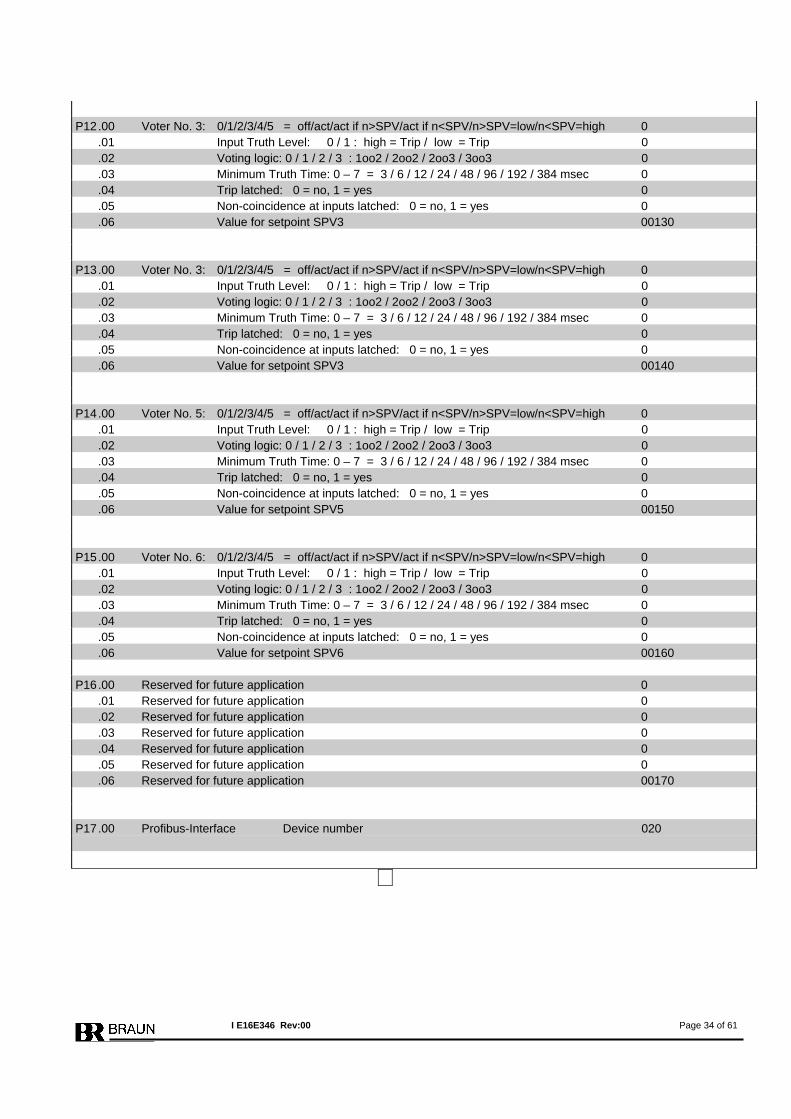
P12 .00 Voter No. 3: 0/1/2/3/4/5 = off/act/act if n>SPV/act if n<SPV/n>SPV=low/n<SPV=high 0 .01 Input Truth Level: 0 / 1 : high = Trip / low = Trip 0 .02 Voting logic: 0 / 1 / 2 / 3 : 1oo2 / 2oo2 / 2oo3 / 3oo3 0 .03 Minimum Truth Time: 0 – 7 = 3 / 6 / 12 / 24 / 48 / 96 / 192 / 384 msec 0 .04 Trip latched: 0 = no, 1 = yes 0 .05 Non-coincidence at inputs latched: 0 = no, 1 = yes 0 .06 Value for setpoint SPV3 00130 P13 .00 Voter No. 3: 0/1/2/3/4/5 = off/act/act if n>SPV/act if n<SPV/n>SPV=low/n<SPV=high 0 .01 Input Truth Level: 0 / 1 : high = Trip / low = Trip 0 .02 Voting logic: 0 / 1 / 2 / 3 : 1oo2 / 2oo2 / 2oo3 / 3oo3 0 .03 Minimum Truth Time: 0 – 7 = 3 / 6 / 12 / 24 / 48 / 96 / 192 / 384 msec 0 .04 Trip latched: 0 = no, 1 = yes 0 .05 Non-coincidence at inputs latched: 0 = no, 1 = yes 0 .06 Value for setpoint SPV3 00140 P14 .00 Voter No. 5: 0/1/2/3/4/5 = off/act/act if n>SPV/act if n<SPV/n>SPV=low/n<SPV=high 0 .01 Input Truth Level: 0 / 1 : high = Trip / low = Trip 0 .02 Voting logic: 0 / 1 / 2 / 3 : 1oo2 / 2oo2 / 2oo3 / 3oo3 0 .03 Minimum Truth Time: 0 – 7 = 3 / 6 / 12 / 24 / 48 / 96 / 192 / 384 msec 0 .04 Trip latched: 0 = no, 1 = yes 0 .05 Non-coincidence at inputs latched: 0 = no, 1 = yes 0 .06 Value for setpoint SPV5 00150 P15 .00 Voter No. 6: 0/1/2/3/4/5 = off/act/act if n>SPV/act if n<SPV/n>SPV=low/n<SPV=high 0 .01 Input Truth Level: 0 / 1 : high = Trip / low = Trip 0 .02 Voting logic: 0 / 1 / 2 / 3 : 1oo2 / 2oo2 / 2oo3 / 3oo3 0 .03 Minimum Truth Time: 0 – 7 = 3 / 6 / 12 / 24 / 48 / 96 / 192 / 384 msec 0 .04 Trip latched: 0 = no, 1 = yes 0 .05 Non-coincidence at inputs latched: 0 = no, 1 = yes 0 .06 Value for setpoint SPV6 00160 P16 .00 Reserved for future application 0 .01 Reserved for future application 0 .02 Reserved for future application 0 .03 Reserved for future application 0 .04 Reserved for future application 0 .05 Reserved for future application 0 .06 Reserved for future application 00170 P17 .00 Profibus-Interface Device number 020
I E16E346 Rev:00 Page 34 of 61
7.2 Description of Parameters and Adjustments of Monitor E1667
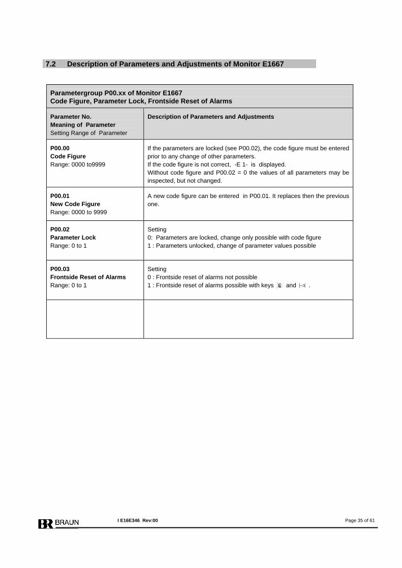
Parametergroup P00.xx of Monitor E1667 Code Figure, Parameter Lock, Frontside Reset of Alarms
Parameter No. Meaning of Parameter Setting Range of Parameter
Description of Parameters and Adjustments
P00.00 Code Figure Range: 0000 to9999
If the parameters are locked (see P00.02), the code figure must be entered prior to any change of other parameters. If the code figure is not correct, -E 1- is displayed. Without code figure and P00.02 = 0 the values of all parameters may be inspected, but not changed.
P00.01 New Code Figure Range: 0000 to 9999
A new code figure can be entered in P00.01. It replaces then the previous one.
P00.02 Parameter Lock Range: 0 to 1
Setting 0: Parameters are locked, change only possible with code figure 1 : Parameters unlocked, change of parameter values possible
P00.03 Frontside Reset of Alarms Range: 0 to 1
Setting 0 : Frontside reset of alarms not possible 1 : Frontside reset of alarms possible with keys and .
I E16E346 Rev:00 Page 35 of 61
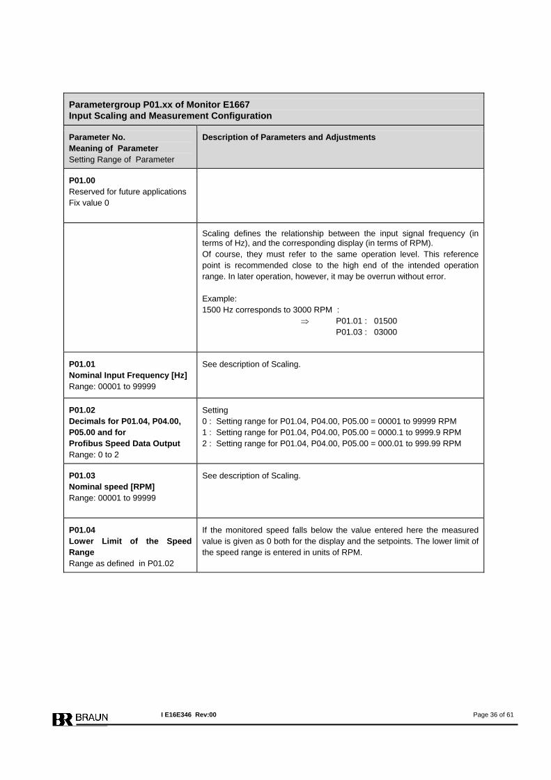
Parametergroup P01.xx of Monitor E1667 Input Scaling and Measurement Configuration
Parameter No. Meaning of Parameter Setting Range of Parameter
Description of Parameters and Adjustments
P01.00 Reserved for future applications Fix value 0
Scaling defines the relationship between the input signal frequency (in terms of Hz), and the corresponding display (in terms of RPM). Of course, they must refer to the same operation level. This reference point is recommended close to the high end of the intended operation range. In later operation, however, it may be overrun without error. Example: 1500 Hz corresponds to 3000 RPM : ⇒ P01.01 : 01500 P01.03 : 03000
P01.01 Nominal Input Frequency [Hz] Range: 00001 to 99999
See description of Scaling.
P01.02 Decimals for P01.04, P04.00, P05.00 and for Profibus Speed Data Output Range: 0 to 2
Setting 0 : Setting range for P01.04, P04.00, P05.00 = 00001 to 99999 RPM 1 : Setting range for P01.04, P04.00, P05.00 = 0000.1 to 9999.9 RPM 2 : Setting range for P01.04, P04.00, P05.00 = 000.01 to 999.99 RPM
P01.03 Nominal speed [RPM] Range: 00001 to 99999
See description of Scaling.
P01.04 Lower Limit of the Speed Range Range as defined in P01.02
If the monitored speed falls below the value entered here the measured value is given as 0 both for the display and the setpoints. The lower limit of the speed range is entered in units of RPM.
I E16E346 Rev:00 Page 36 of 61
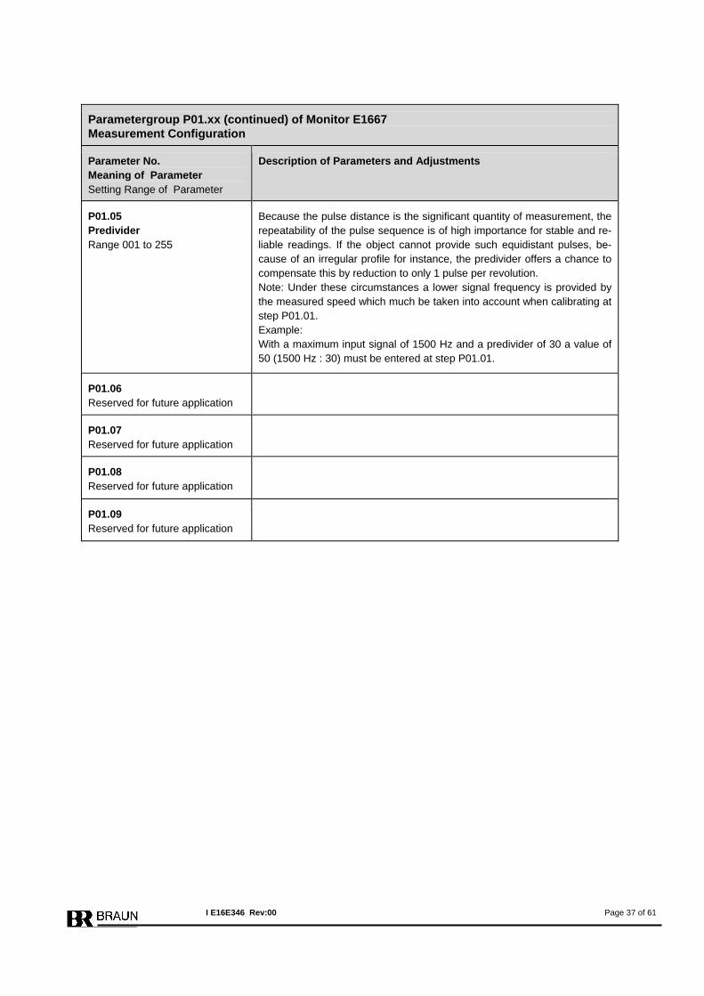
Parametergroup P01.xx (continued) of Monitor E1667 Measurement Configuration
Parameter No. Meaning of Parameter Setting Range of Parameter
Description of Parameters and Adjustments
P01.05 Predivider Range 001 to 255
Because the pulse distance is the significant quantity of measurement, the repeatability of the pulse sequence is of high importance for stable and re-liable readings. If the object cannot provide such equidistant pulses, be-cause of an irregular profile for instance, the predivider offers a chance to compensate this by reduction to only 1 pulse per revolution. Note: Under these circumstances a lower signal frequency is provided by the measured speed which much be taken into account when calibrating at step P01.01. Example: With a maximum input signal of 1500 Hz and a predivider of 30 a value of 50 (1500 Hz : 30) must be entered at step P01.01.
P01.06 Reserved for future application
P01.07 Reserved for future application
P01.08 Reserved for future application
P01.09 Reserved for future application
I E16E346 Rev:00 Page 37 of 61
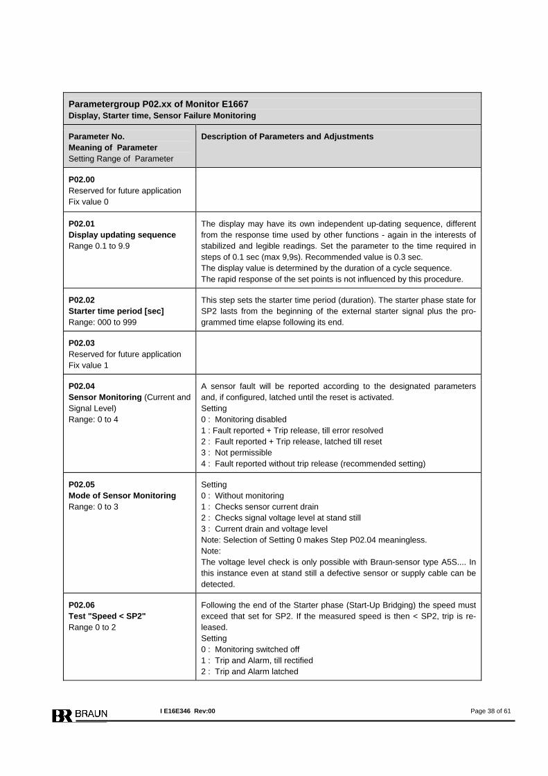
Parametergroup P02.xx of Monitor E1667 Display, Starter time, Sensor Failure Monitoring
Parameter No. Meaning of Parameter Setting Range of Parameter
Description of Parameters and Adjustments
P02.00 Reserved for future application Fix value 0
P02.01 Display updating sequence Range 0.1 to 9.9
The display may have its own independent up-dating sequence, different from the response time used by other functions - again in the interests of stabilized and legible readings. Set the parameter to the time required in steps of 0.1 sec (max 9,9s). Recommended value is 0.3 sec. The display value is determined by the duration of a cycle sequence. The rapid response of the set points is not influenced by this procedure.
P02.02 Starter time period [sec] Range: 000 to 999
This step sets the starter time period (duration). The starter phase state for SP2 lasts from the beginning of the external starter signal plus the pro-grammed time elapse following its end.
P02.03 Reserved for future application Fix value 1
P02.04 Sensor Monitoring (Current and Signal Level) Range: 0 to 4
A sensor fault will be reported according to the designated parameters and, if configured, latched until the reset is activated. Setting 0 : Monitoring disabled 1 : Fault reported + Trip release, till error resolved 2 : Fault reported + Trip release, latched till reset 3 : Not permissible 4 : Fault reported without trip release (recommended setting)
P02.05 Mode of Sensor Monitoring Range: 0 to 3
Setting 0 : Without monitoring 1 : Checks sensor current drain 2 : Checks signal voltage level at stand still 3 : Current drain and voltage level Note: Selection of Setting 0 makes Step P02.04 meaningless. Note: The voltage level check is only possible with Braun-sensor type A5S.... In this instance even at stand still a defective sensor or supply cable can be detected.
P02.06 Test "Speed < SP2" Range 0 to 2
Following the end of the Starter phase (Start-Up Bridging) the speed must exceed that set for SP2. If the measured speed is then < SP2, trip is re-leased. Setting 0 : Monitoring switched off 1 : Trip and Alarm, till rectified 2 : Trip and Alarm latched
I E16E346 Rev:00 Page 38 of 61
Parametergroup P02.xx (continued) of Monitor E1667 Sensor Failure Monitoring
Parameter No. Meaning of Parameter Setting Range of Parameter
Description of Parameters and Adjustments
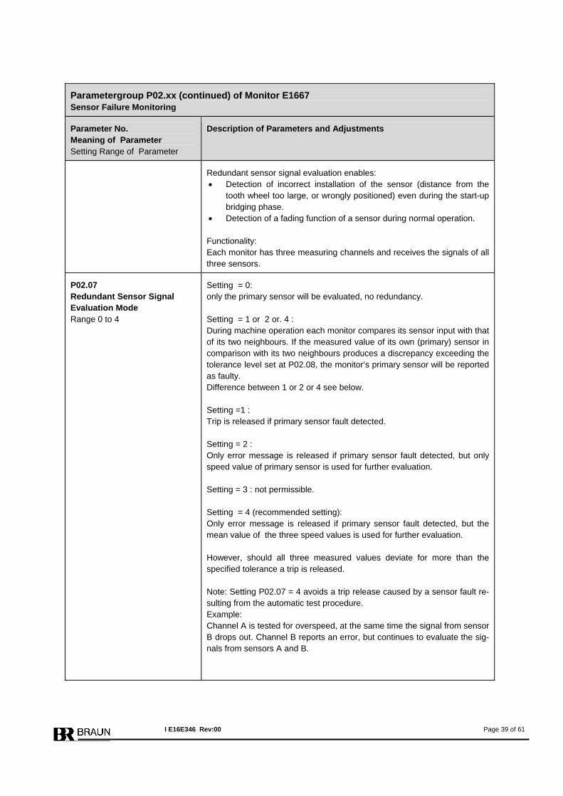
Redundant sensor signal evaluation enables: • Detection of incorrect installation of the sensor (distance from the
tooth wheel too large, or wrongly positioned) even during the start-up bridging phase.
• Detection of a fading function of a sensor during normal operation. Functionality: Each monitor has three measuring channels and receives the signals of all three sensors.
P02.07 Redundant Sensor Signal Evaluation Mode Range 0 to 4
Setting = 0: only the primary sensor will be evaluated, no redundancy. Setting = 1 or 2 or. 4 : During machine operation each monitor compares its sensor input with that of its two neighbours. If the measured value of its own (primary) sensor in comparison with its two neighbours produces a discrepancy exceeding the tolerance level set at P02.08, the monitor’s primary sensor will be reported as faulty. Difference between 1 or 2 or 4 see below. Setting =1 : Trip is released if primary sensor fault detected. Setting = 2 : Only error message is released if primary sensor fault detected, but only speed value of primary sensor is used for further evaluation. Setting = 3 : not permissible. Setting = 4 (recommended setting): Only error message is released if primary sensor fault detected, but the mean value of the three speed values is used for further evaluation. However, should all three measured values deviate for more than the specified tolerance a trip is released. Note: Setting P02.07 = 4 avoids a trip release caused by a sensor fault re-sulting from the automatic test procedure. Example: Channel A is tested for overspeed, at the same time the signal from sensor B drops out. Channel B reports an error, but continues to evaluate the sig-nals from sensors A and B.
I E16E346 Rev:00 Page 39 of 61
Parametergroup P02.xx (continued) of Monitor E1667 Sensor Failure Monitoring
Parameter No. Meaning of Parameter Setting Range of Parameter
Description of Parameters and Adjustments
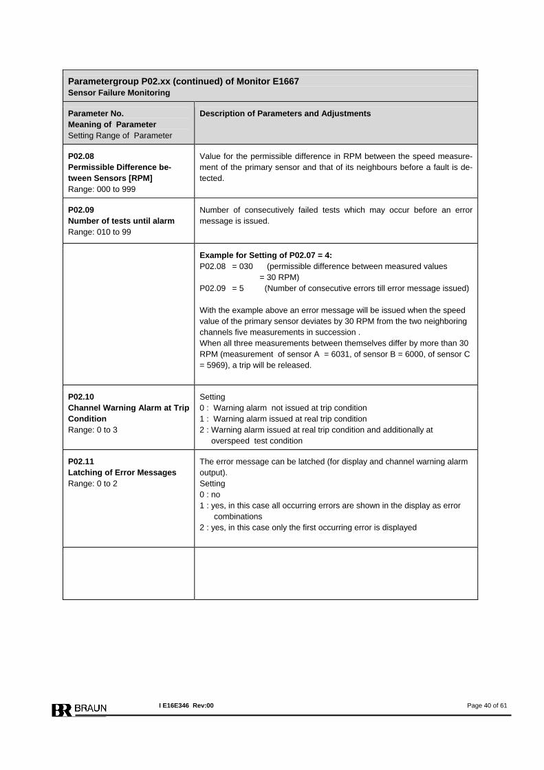
P02.08 Permissible Difference be-tween Sensors [RPM] Range: 000 to 999
Value for the permissible difference in RPM between the speed measure-ment of the primary sensor and that of its neighbours before a fault is de-tected.
P02.09 Number of tests until alarm Range: 010 to 99
Number of consecutively failed tests which may occur before an error message is issued.
Example for Setting of P02.07 = 4: P02.08 = 030 (permissible difference between measured values = 30 RPM) P02.09 = 5 (Number of consecutive errors till error message issued) With the example above an error message will be issued when the speed value of the primary sensor deviates by 30 RPM from the two neighboring channels five measurements in succession . When all three measurements between themselves differ by more than 30 RPM (measurement of sensor A = 6031, of sensor B = 6000, of sensor C = 5969), a trip will be released.
P02.10 Channel Warning Alarm at Trip Condition Range: 0 to 3
Setting 0 : Warning alarm not issued at trip condition 1 : Warning alarm issued at real trip condition 2 : Warning alarm issued at real trip condition and additionally at overspeed test condition
P02.11 Latching of Error Messages Range: 0 to 2
The error message can be latched (for display and channel warning alarm output). Setting 0 : no 1 : yes, in this case all occurring errors are shown in the display as error combinations 2 : yes, in this case only the first occurring error is displayed
I E16E346 Rev:00 Page 40 of 61
Parametergroup P03.xx of Monitor E1667 Overspeed Alarm SP1
Parameter No. Meaning of Parameter Setting Range of Parameter
Description of Parameters and Adjustments
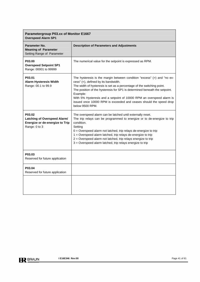
P03.00 Overspeed Setpoint SP1 Range: 00001 to 99999
The numerical value for the setpoint is expressed as RPM.
P03.01 Alarm Hysteresis Width Range: 00.1 to 99.9
The hysteresis is the margin between condition "excess" (>) and "no ex-cess" (<), defined by its bandwidth. The width of hysteresis is set as a percentage of the switching point. The position of the hysteresis for SP1 is determined beneath the setpoint. Example: With 5% Hysteresis and a setpoint of 10000 RPM an overspeed alarm is issued once 10000 RPM is exceeded and ceases should the speed drop below 9500 RPM.
P03.02 Latching of Overspeed Alarm/ Energize or de-energize to Trip Range: 0 to 3
The overspeed alarm can be latched until externally reset. The trip relays can be programmed to energize or to de-energize to trip condition. Setting 0 = Overspeed alarm not latched, trip relays de-energize to trip 1 = Overspeed alarm latched, trip relays de-energize to trip 2 = Overspeed alarm not latched, trip relays energize to trip 3 = Overspeed alarm latched, trip relays energize to trip
P03.03 Reserved for future application
P03.04 Reserved for future application
I E16E346 Rev:00 Page 41 of 61
Parametergroup P04.xx of Monitor E1667 Lowspeed Alarm SP2
Parameter No. Meaning of Parameter Setting Range of Parameter
Description of Parameters and Adjustments
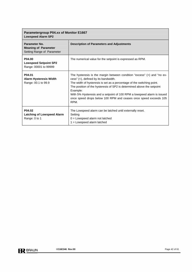
P04.00 Lowspeed Setpoint SP2 Range: 00001 to 99999
The numerical value for the setpoint is expressed as RPM.
P04.01 Alarm Hysteresis Width Range: 00.1 to 99.9
The hysteresis is the margin between condition "excess" (>) and "no ex-cess" (<), defined by its bandwidth. The width of hysteresis is set as a percentage of the switching point. The position of the hysteresis of SP2 is determined above the setpoint Example: With 5% Hysteresis and a setpoint of 100 RPM a lowspeed alarm is issued once speed drops below 100 RPM and ceases once speed exceeds 105 RPM.
P04.02 Latching of Lowspeed Alarm Range: 0 to 1
The Lowspeed alarm can be latched until externally reset. Setting 0 = Lowspeed alarm not latched 1 = Lowspeed alarm latched
I E16E346 Rev:00 Page 42 of 61
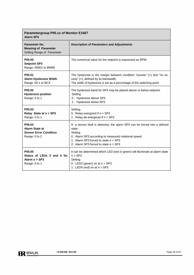
Parametergroup P05.xx of Monitor E1667 Alarm SP3
Parameter No. Meaning of Parameter Setting Range of Parameter
Description of Parameters and Adjustments
P05.00 Setpoint SP3 Range: 00001 to 99999
The numerical value for the setpoint is expressed as RPM.
P05.01 Alarm Hysteresis Width Range: 00.1 to 99.9
The hysteresis is the margin between condition "excess" (>) and "no ex-cess" (<), defined by its bandwidth. The width of hysteresis is set as a percentage of the switching point.
P05.02 Hysteresis position Range: 0 to 1
The hysteresis band for SP3 may be placed above or below setpoint. Setting 0 : Hysteresis above SP3 1 : Hysteresis below SP3
P05.03 Relay State at n > SP3 Range: 0 to 1
Setting 0 : Relay energized if n > SP3 1 : Relay de-energized if n > SP3
P05.04 Alarm State at Sensor Error Condition Range: 0 to 2
If a sensor fault is detected, the alarm SP3 can be forced into a defined state. Setting 0 : Alarm SP3 according to measured rotational speed 1: Alarm SP3 forced to state n < SP3 2: Alarm SP3 forced to state n > SP3
P05.05 Status of LEDs 3 and 4 for Alarm n > SP3 Range: 0 to 1
It can be determined which LED (red or green) will illuminate at alarm state n > SP3. Setting 0 : LED3 (green) on at n > SP3 1 : LED4 (red) on at n > SP3
I E16E346 Rev:00 Page 43 of 61
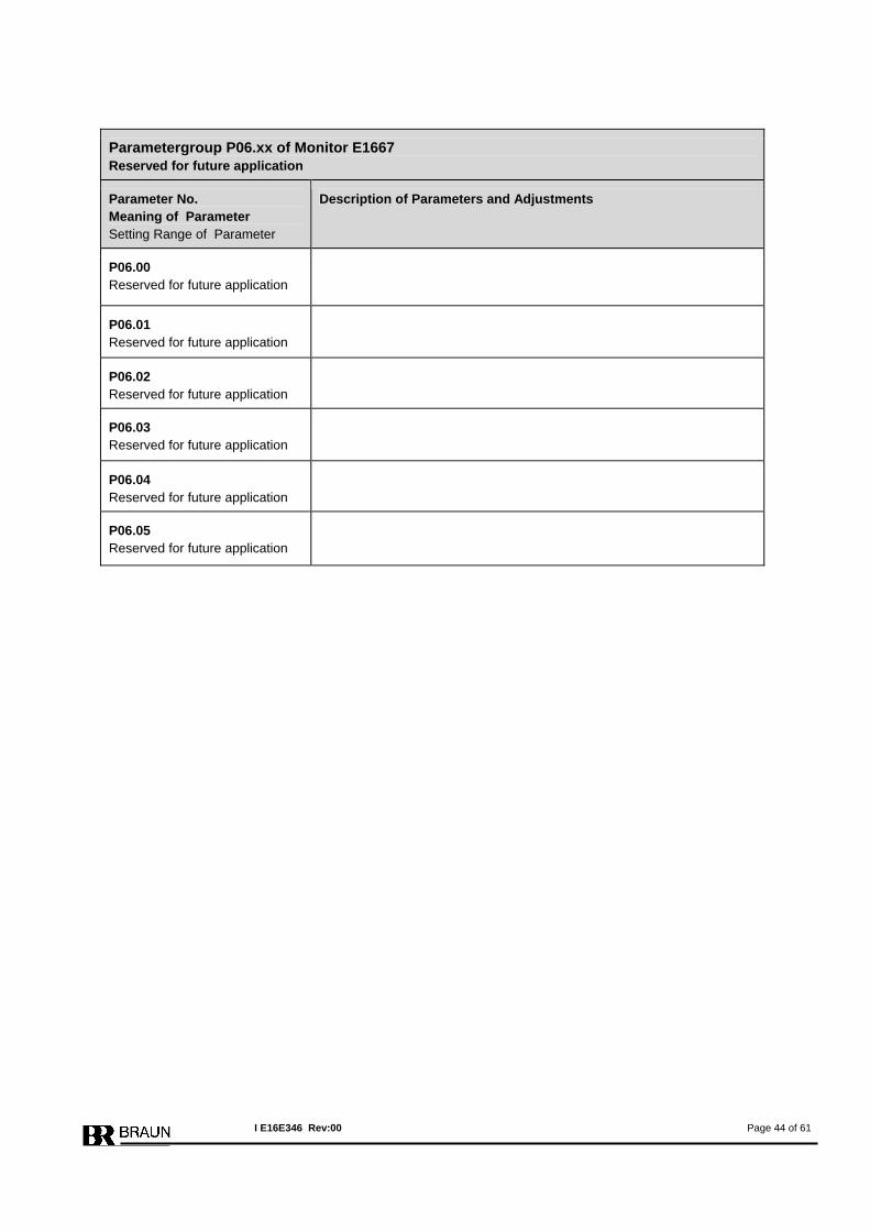
Parametergroup P06.xx of Monitor E1667 Reserved for future application
Parameter No. Meaning of Parameter Setting Range of Parameter
Description of Parameters and Adjustments
P06.00 Reserved for future application
P06.01 Reserved for future application
P06.02 Reserved for future application
P06.03 Reserved for future application
P06.04 Reserved for future application
P06.05 Reserved for future application
I E16E346 Rev:00 Page 44 of 61
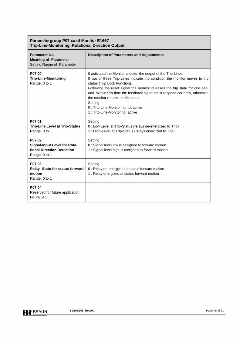
Parametergroup P07.xx of Monitor E1667 Trip-Line-Monitoring, Rotational Direction Output
Parameter No. Meaning of Parameter Setting Range of Parameter
Description of Parameters and Adjustments
P07.00 Trip-Line-Monitoring Range: 0 to 1
If activated the Monitor checks the output of the Trip-Lines. If two or three Trip-Lines indicate trip condition the monitor moves to trip status (Trip Lock Function). Following the reset signal the monitor releases the trip state for one sec-ond. Within this time the feedback signal must respond correctly, otherwise the monitor returns to trip status. Setting 0 : Trip-Line-Monitoring not active 1 : Trip-Line-Monitoring active
P07.01 Trip-Line Level at Trip-Status Range: 0 to 1
Setting 0 : Low Level at Trip-Status (relays de-energized to Trip) 1 : High-Level at Trip-Status (relays energized to Trip)
P07.02 Signal-Input Level for Rota-tional Direction Detection Range: 0 to 1
Setting 0 : Signal level low is assigned to forward motion 1 : Signal level high is assigned to forward motion
P07.03 Relay State for status forward motion Range: 0 to 1
Setting 0 : Relay de-energized at status forward motion 1 : Relay energized at status forward motion
P07.04 Reserved for future application. Fix value 0
I E16E346 Rev:00 Page 45 of 61
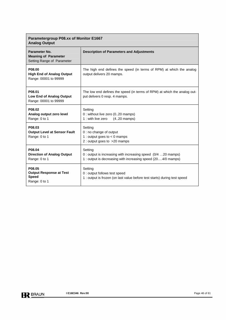
Parametergroup P08.xx of Monitor E1667 Analog Output
Parameter No. Meaning of Parameter Setting Range of Parameter
Description of Parameters and Adjustments
P08.00 High End of Analog Output Range: 00001 to 99999
The high end defines the speed (in terms of RPM) at which the analog output delivers 20 mamps.
P08.01 Low End of Analog Output Range: 00001 to 99999
The low end defines the speed (in terms of RPM) at which the analog out-put delivers 0 resp. 4 mamps.
P08.02 Analog output zero level Range: 0 to 1
Setting 0 : without live zero (0..20 mamps) 1 : with live zero (4..20 mamps)
P08.03 Output Level at Sensor Fault Range: 0 to 1
Setting 0 : no change of output 1 : output goes to < 0 mamps 2 : output goes to >20 mamps
P08.04 Direction of Analog Output Range: 0 to 1
Setting 0 : output is increasing with increasing speed (0/4 …20 mamps) 1 : output is decreasing with increasing speed (20….4/0 mamps)
P08.05 Output Response at Test Speed Range: 0 to 1
Setting 0 : output follows test speed 1 : output is frozen (on last value before test starts) during test speed
I E16E346 Rev:00 Page 46 of 61
Parametergroup P09.xx of Monitor E1667 Reserved for future application
Parameter No. Meaning of Parameter Setting Range of Parameter
Description of Parameters and Adjustments
P09.00 Reserved for future application
I E16E346 Rev:00 Page 47 of 61

Parametergroup P10.xx of Monitor E1667 Voter 1 , Logic Output LO1
Parameter No. Meaning of Parameter Setting Range of Parameter
Description of Parameters and Adjustments
P10.00 Voter 1 active resp. LO1 Range: 0 to 5
Setting 0 : Voter inactive 1 : Voter always active (over entire speed range) 2 : Voter only active, if n > SPV1 3 : Voter only active, if n < SPV1 4 : Voter inactive, output LO1 low, if n > SPV1 5 : Voter inactive, output LO1 high, if n > SPV1
P10.01 Input Truth Level Range: 0 to 1
Setting 0 = high level at inputs is assigned to trip condition 1 = low level at inputs is assigned to trip condition
P10.02 Voting Logic Range: 0 to 3
Selectable Voting Logics are: 1oo2 : trip is released if 1of 2 inputs signalizes trip condition 2oo2 : trip is released if 2 of 2 inputs signalize trip condition 2oo3 : trip is released if 2 of 3 inputs signalize trip condition 3oo3 : trip is released if 3 of 3 inputs signalize trip condition Setting 0 : 1oo2 (only inputs 1 and 2 of voter 1 are monitored) 1 : 2oo2 (only inputs 1 and 2 of voter 1 are monitored) 2 : 2oo3 (all three inputs of voter 1 are monitored) 3 : 3oo3 (all three inputs of voter 1 are monitored)
P10.03 Minimum Truth Time Range: 0 to 7
If the trip signal at the input is shorter than the minimum truth time, the signal is not valid (anti bouncing filter). Setting for minimal truth time: 0 : 3 msec 1 : 6 msec 2 : 12 msec 3 : 24 msec 4 : 48 msec 5 : 96 msec 6 : 192 msec 7 : 384 msec
P10.04 Trip by Voter 1 latched Range: 0 to 1
Setting 0 : trip by voter 1 is not latched 1 : trip by voter 1 is latched until reset
P10.05 Discrepancy at Inputs latched Range: 0 to 1
Setting 0 : Discrepancy at inputs of voter 1 is not latched 1 : Non-coincidence at inputs of voter 1 is latched until reset
P10.06 Setpoint SPV1 Range: 00001 to 99999
Depending on setting of P10.00, SPV1 controls the activity of voter 1 or controls directly the output LO1. SPV1 is set in terms of RPM.
I E16E346 Rev:00 Page 48 of 61
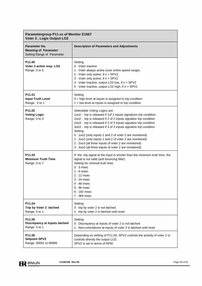
Parametergroup P11.xx of Monitor E1667 Voter 2 , Logic Output LO2
Parameter No. Meaning of Parameter Setting Range of Parameter
Description of Parameters and Adjustments
P11.00 Voter 2 active resp. LO2 Range: 0 to 5
Setting 0 : Voter inactive 1 : Voter always active (over entire speed range) 2 : Voter only active, if n > SPV2 3 : Voter only active, if n < SPV2 4 : Voter inactive, output LO2 low, if n > SPV2 5 : Voter inactive, output LO2 high, if n > SPV2
P11.01 Input Truth Level Range: 0 to 1
Setting 0 = high level at inputs is assigned to trip condition 1 = low level at inputs is assigned to trip condition
P11.02 Voting Logic Range: 0 to 3
Selectable Voting Logics are: 1oo2 : trip is released if 1of 2 inputs signalizes trip condition 2oo2 : trip is released if 2 of 2 inputs signalize trip condition 2oo3 : trip is released if 2 of 3 inputs signalize trip condition 3oo3 : trip is released if 3 of 3 inputs signalize trip condition Setting 0 : 1oo2 (only inputs 1 and 2 of voter 2 are monitored) 1 : 2oo2 (only inputs 1 and 2 of voter 2 are monitored) 2 : 2oo3 (all three inputs of voter 2 are monitored) 3 : 3oo3 (all three inputs of voter 2 are monitored)
P11.03 Minimum Truth Time Range: 0 to 7
If the trip signal at the input is shorter than the minimum truth time, the signal is not valid (anti bouncing filter). Setting for minimal truth time: 0 : 3 msec 1 : 6 msec 2 : 12 msec 3 : 24 msec 4 : 48 msec 5 : 96 msec 6 : 192 msec 7 : 384 msec
P11.04 Trip by Voter 2 latched Range: 0 to 1
Setting 0 : trip by voter 2 is not latched 1 : trip by voter 2 is latched until reset
P11.05 Discrepancy at Inputs latched Range: 0 to 1
Setting 0 : Discrepancy at inputs of voter 2 is not latched 1 : Non-coincidence at inputs of voter 2 is latched until reset
P11.06 Setpoint SPV2 Range: 00001 to 99999
Depending on setting of P11.00, SPV2 controls the activity of voter 2 or controls directly the output LO2. SPV2 is set in terms of RPM.
I E16E346 Rev:00 Page 49 of 61

Parametergroup P12.xx of Monitor E1667 Voter 3 , Logic Output LO3
Parameter No. Meaning of Parameter Setting Range of Parameter
Description of Parameters and Adjustments
P12.00 Voter 3 active resp. LO3 Range: 0 to 5
Setting 0 : Voter inactive 1 : Voter always active (over entire speed range) 2 : Voter only active, if n > SPV3 3 : Voter only active, if n < SPV3 4 : Voter inactive, output LO3 low, if n > SPV3 5 : Voter inactive, output LO3 high, if n > SPV3
P12.01 Input Truth Level Range: 0 to 1
Setting 0 = high level at inputs is assigned to trip condition 1 = low level at inputs is assigned to trip condition
P12.02 Voting Logic Range: 0 to 3
Selectable Voting Logics are: 1oo2 : trip is released if 1of 2 inputs signalizes trip condition 2oo2 : trip is released if 2 of 2 inputs signalize trip condition 2oo3 : trip is released if 2 of 3 inputs signalize trip condition 3oo3 : trip is released if 3 of 3 inputs signalize trip condition Setting 0 : 1oo2 (only inputs 1 and 2 of voter 3 are monitored) 1 : 2oo2 (only inputs 1 and 2 of voter 3 are monitored) 2 : 2oo3 (all three inputs of voter 3 are monitored) 3 : 3oo3 (all three inputs of voter 3 are monitored)
P12.03 Minimum Truth Time Range: 0 to 7
If the trip signal at the input is shorter than the minimum truth time, the signal is not valid (anti bouncing filter). Setting for minimal truth time: 0 : 3 msec 1 : 6 msec 2 : 12 msec 3 : 24 msec 4 : 48 msec 5 : 96 msec 6 : 192 msec 7 : 384 msec
P12.04 Trip by Voter3 latched Range: 0 to 1
Setting 0 : trip by voter 3 is not latched 1 : trip by voter 3 is latched until reset
P12.05 Discrepancy at Inputs latched Range: 0 to 1
Setting 0 : Discrepancy at inputs of voter 3 is not latched 1 : Non-coincidence at inputs of voter 3 is latched until reset
P12.06 Setpoint SPV3 Range: 00001 to 99999
Depending on setting of P12.00, SPV3 controls the activity of voter 3 or controls directly the output LO3. SPV3 is set in terms of RPM.
I E16E346 Rev:00 Page 50 of 61

Parametergroup P13.xx of Monitor E1667 Voter 4 , Logic Output LO4
Parameter No. Meaning of Parameter Setting Range of Parameter
Description of Parameters and Adjustments
P13.00 Voter 4 active resp. LO4 Range: 0 to 5
Setting 0 : Voter inactive 1 : Voter always active (over entire speed range) 2 : Voter only active, if n > SPV4 3 : Voter only active, if n < SPV4 4 : Voter inactive, output LO4 low, if n > SPV4 5 : Voter inactive, output LO4 high, if n > SPV4
P13.01 Input Truth Level Range: 0 to 1
Setting 0 = high level at inputs is assigned to trip condition 1 = low level at inputs is assigned to trip condition
P13.02 Voting Logic Range: 0 to 3
Selectable Voting Logics are: 1oo2 : trip is released if 1of 2 inputs signalizes trip condition 2oo2 : trip is released if 2 of 2 inputs signalize trip condition 2oo3 : trip is released if 2 of 3 inputs signalize trip condition 3oo3 : trip is released if 3 of 3 inputs signalize trip condition Setting 0 : 1oo2 (only inputs 1 and 2 of voter 4 are monitored) 1 : 2oo2 (only inputs 1 and 2 of voter 4 are monitored) 2 : 2oo3 (all three inputs of voter 4 are monitored) 3 : 3oo3 (all three inputs of voter 4 are monitored)
P13.03 Minimum Truth Time Range: 0 to 7
If the trip signal at the input is shorter than the minimum truth time, the signal is not valid (anti bouncing filter). Setting for minimal truth time: 0 : 3 msec 1 : 6 msec 2 : 12 msec 3 : 24 msec 4 : 48 msec 5 : 96 msec 6 : 192 msec 7 : 384 msec
P13.04 Trip by Voter 4 latched Range: 0 to 1
Setting 0 : trip by voter 4 is not latched 1 : trip by voter 4 is latched until reset
P13.05 Discrepancy at Inputs latched Range: 0 to 1
Setting 0 : Discrepancy at inputs of voter 4 is not latched 1 : Non-coincidence at inputs of voter 4 is latched until reset
P13.06 Setpoint SPV4 Range: 00001 to 99999
Depending on setting of P13.00, SPV4 controls the activity of voter 4 or controls directly the output LO4. SPV4 is set in terms of RPM.
I E16E346 Rev:00 Page 51 of 61

Parametergroup P14.xx of Monitor E1667 Voter 5 , Logic Output LO5
Parameter No. Meaning of Parameter Setting Range of Parameter
Description of Parameters and Adjustments
P14.00 Voter 5 active resp. LO5 Range: 0 to 5
Setting 0 : Voter inactive 1 : Voter always active (over entire speed range) 2 : Voter only active, if n > SPV5 3 : Voter only active, if n < SPV5 4 : Voter inactive, output LO5 low, if n > SPV5 5 : Voter inactive, output LO5 high, if n > SPV5
P14.01 Input Truth Level Range: 0 to 1
Setting 0 = high level at inputs is assigned to trip condition 1 = low level at inputs is assigned to trip condition
P14.02 Voting Logic Range: 0 to 3
Selectable Voting Logics are: 1oo2 : trip is released if 1of 2 inputs signalizes trip condition 2oo2 : trip is released if 2 of 2 inputs signalize trip condition 2oo3 : trip is released if 2 of 3 inputs signalize trip condition 3oo3 : trip is released if 3 of 3 inputs signalize trip condition Setting 0 : 1oo2 (only inputs 1 and 2 of voter 5 are monitored) 1 : 2oo2 (only inputs 1 and 2 of voter 5 are monitored) 2 : 2oo3 (all three inputs of voter 5 are monitored) 3 : 3oo3 (all three inputs of voter 5 are monitored)
P14.03 Minimum Truth Time Range: 0 to 7
If the trip signal at the input is shorter than the minimum truth time, the signal is not valid (anti bouncing filter). Setting for minimal truth time: 0 : 3 msec 1 : 6 msec 2 : 12 msec 3 : 24 msec 4 : 48 msec 5 : 96 msec 6 : 192 msec 7 : 384 msec
P14.04 Trip by Voter 5 latched Range: 0 to 1
Setting 0 : trip by voter 5 is not latched 1 : trip by voter 5 is latched until reset
P14.05 Discrepancy at Inputs latched Range: 0 to 1
Setting 0 : Discrepancy at inputs of voter 5 is not latched 1 : Non-coincidence at inputs of voter 5 is latched until reset
P14.06 Setpoint SPV5 Range: 00001 to 99999
Depending on setting of P14.00, SPV5 controls the activity of voter 5 or controls directly the output LO5. SPV5 is set in terms of RPM.
I E16E346 Rev:00 Page 52 of 61

Parametergroup P15.xx of Monitor E1667 Voter 6 , Logic Output LO6
Parameter No. Meaning of Parameter Setting Range of Parameter
Description of Parameters and Adjustments
P15.00 Voter 6 active resp. LO6 Range: 0 to 5
Setting 0 : Voter inactive 1 : Voter always active (over entire speed range) 2 : Voter only active, if n > SPV6 3 : Voter only active, if n < SPV6 4 : Voter inactive, output LO6 low, if n > SPV6 5 : Voter inactive, output LO6 high, if n > SPV6
P15.01 Input Truth Level Range: 0 to 1
Setting 0 = high level at inputs is assigned to trip condition 1 = low level at inputs is assigned to trip condition
P15.02 Voting Logic Range: 0 to 3
Selectable Voting Logics are: 1oo2 : trip is released if 1of 2 inputs signalizes trip condition 2oo2 : trip is released if 2 of 2 inputs signalize trip condition 2oo3 : trip is released if 2 of 3 inputs signalize trip condition 3oo3 : trip is released if 3 of 3 inputs signalize trip condition Setting 0 : 1oo2 (only inputs 1 and 2 of voter 6 are monitored) 1 : 2oo2 (only inputs 1 and 2 of voter 6 are monitored) 2 : 2oo3 (all three inputs of voter 6 are monitored) 3 : 3oo3 (all three inputs of voter 6 are monitored)
P15.03 Minimum Truth Time Range: 0 to 7
If the trip signal at the input is shorter than the minimum truth time, the signal is not valid (anti bouncing filter). Setting for minimal truth time: 0 : 3 msec 1 : 6 msec 2 : 12 msec 3 : 24 msec 4 : 48 msec 5 : 96 msec 6 : 192 msec 7 : 384 msec
P15.04 Trip by Voter 6 latched Range: 0 to 1
Setting 0 : trip by voter 6 is not latched 1 : trip by voter 6 is latched until reset
P15.05 Discrepancy at Inputs latched Range: 0 to 1
Setting 0 : Discrepancy at inputs of voter 6 is not latched 1 : Non-coincidence at inputs of voter 6 is latched until reset
P15.06 Setpoint SPV6 Range: 00001 to 99999
Depending on setting of P15.00, SPV6 controls the activity of voter 6 or controls directly the output LO6. SPV5 is set in terms of RPM.
I E16E346 Rev:00 Page 53 of 61
Parametergroup P16.xx of Monitor E1667 Reserved for future application
Parameter No. Meaning of Parameter Setting Range of Parameter
Description of Parameters and Adjustments
P16.00 Reserved for future application
P16.01 Reserved for future application
P16.02 Reserved for future application
P16.03 Reserved for future application
P16.04 Reserved for future application
P16.05 Reserved for future application
P16.06 Reserved for future application
I E16E346 Rev:00 Page 54 of 61

Parametergroup P17.xx of Monitor E1667 PROFIBUS
Parameter No. Meaning of Parameter Setting Range of Parameter
Description of Parameters and Adjustments
P17.00 Device No for PROFIBUS Range: 001 to 125
All members of the PROFIBUS-Communication must have different device nos.
I E16E346 Rev:00 Page 55 of 61
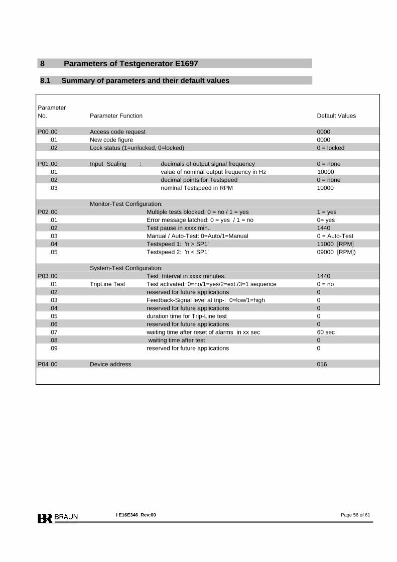
8 Parameters of Testgenerator E1697 8.1 Summary of parameters and their default values
Parameter No. Parameter Function Default Values P00 .00 Access code request 0000 .01 New code figure 0000 .02 Lock status (1=unlocked, 0=locked) 0 = locked P01 .00 Input Scaling : decimals of output signal frequency 0 = none .01 value of nominal output frequency in Hz 10000 .02 decimal points for Testspeed 0 = none .03 nominal Testspeed in RPM 10000 Monitor-Test Configuration: P02 .00 Multiple tests blocked: 0 = no / 1 = yes 1 = yes .01 Error message latched: 0 = yes / 1 = no 0= yes .02 Test pause in xxxx min.. 1440 .03 Manual / Auto-Test: 0=Auto/1=Manual 0 = Auto-Test .04 Testspeed 1: 'n > SP1' 11000 [RPM] .05 Testspeed 2: 'n < SP1' 09000 [RPM]) System-Test Configuration: P03 .00 Test Interval in xxxx minutes. 1440 .01 TripLine Test Test activated: 0=no/1=yes/2=ext./3=1 sequence 0 = no .02 reserved for future applications 0 .03 Feedback-Signal level at trip-: 0=low/1=high 0 .04 reserved for future applications 0 .05 duration time for Trip-Line test 0 .06 reserved for future applications 0 .07 waiting time after reset of alarms in xx sec 60 sec .08 waiting time after test 0 .09 reserved for future applications 0 P04 .00 Device address 016
I E16E346 Rev:00 Page 56 of 61
8.2 Description of Parameters and Adjustments of Testgenerator E1697
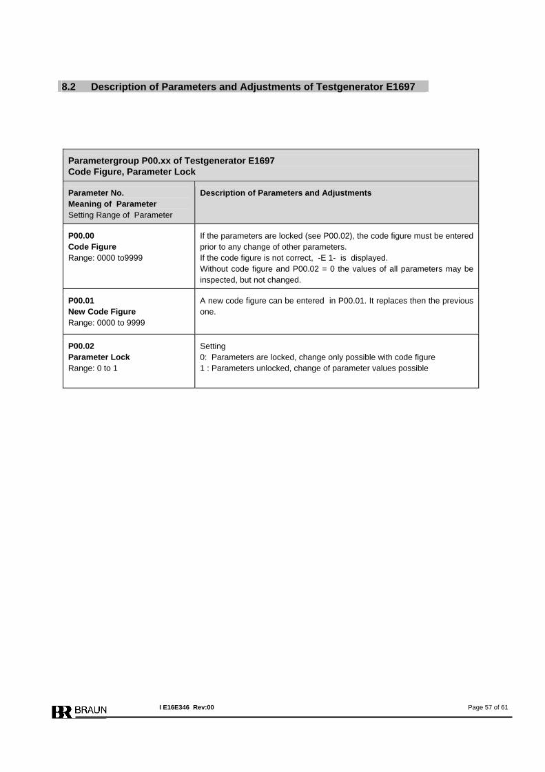
Parametergroup P00.xx of Testgenerator E1697 Code Figure, Parameter Lock
Parameter No. Meaning of Parameter Setting Range of Parameter
Description of Parameters and Adjustments
P00.00 Code Figure Range: 0000 to9999
If the parameters are locked (see P00.02), the code figure must be entered prior to any change of other parameters. If the code figure is not correct, -E 1- is displayed. Without code figure and P00.02 = 0 the values of all parameters may be inspected, but not changed.
P00.01 New Code Figure Range: 0000 to 9999
A new code figure can be entered in P00.01. It replaces then the previous one.
P00.02 Parameter Lock Range: 0 to 1
Setting 0: Parameters are locked, change only possible with code figure 1 : Parameters unlocked, change of parameter values possible
I E16E346 Rev:00 Page 57 of 61
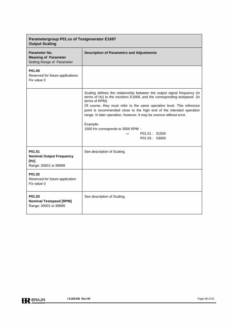
Parametergroup P01.xx of Testgenerator E1697 Output Scaling
Parameter No. Meaning of Parameter Setting Range of Parameter
Description of Parameters and Adjustments
P01.00 Reserved for future applications Fix value 0
Scaling defines the relationship between the output signal frequency (in terms of Hz) to the monitors E1668, and the corresponding testspeed (in terms of RPM). Of course, they must refer to the same operation level. This reference point is recommended close to the high end of the intended operation range. In later operation, however, it may be overrun without error. Example: 1500 Hz corresponds to 3000 RPM : ⇒ P01.01 : 01500 P01.03 : 03000
P01.01 Nominal Output Frequency [Hz] Range: 00001 to 99999
See description of Scaling.
P01.02 Reserved for future application Fix value 0
P01.03 Nominal Testspeed [RPM] Range: 00001 to 99999
See description of Scaling.
I E16E346 Rev:00 Page 58 of 61
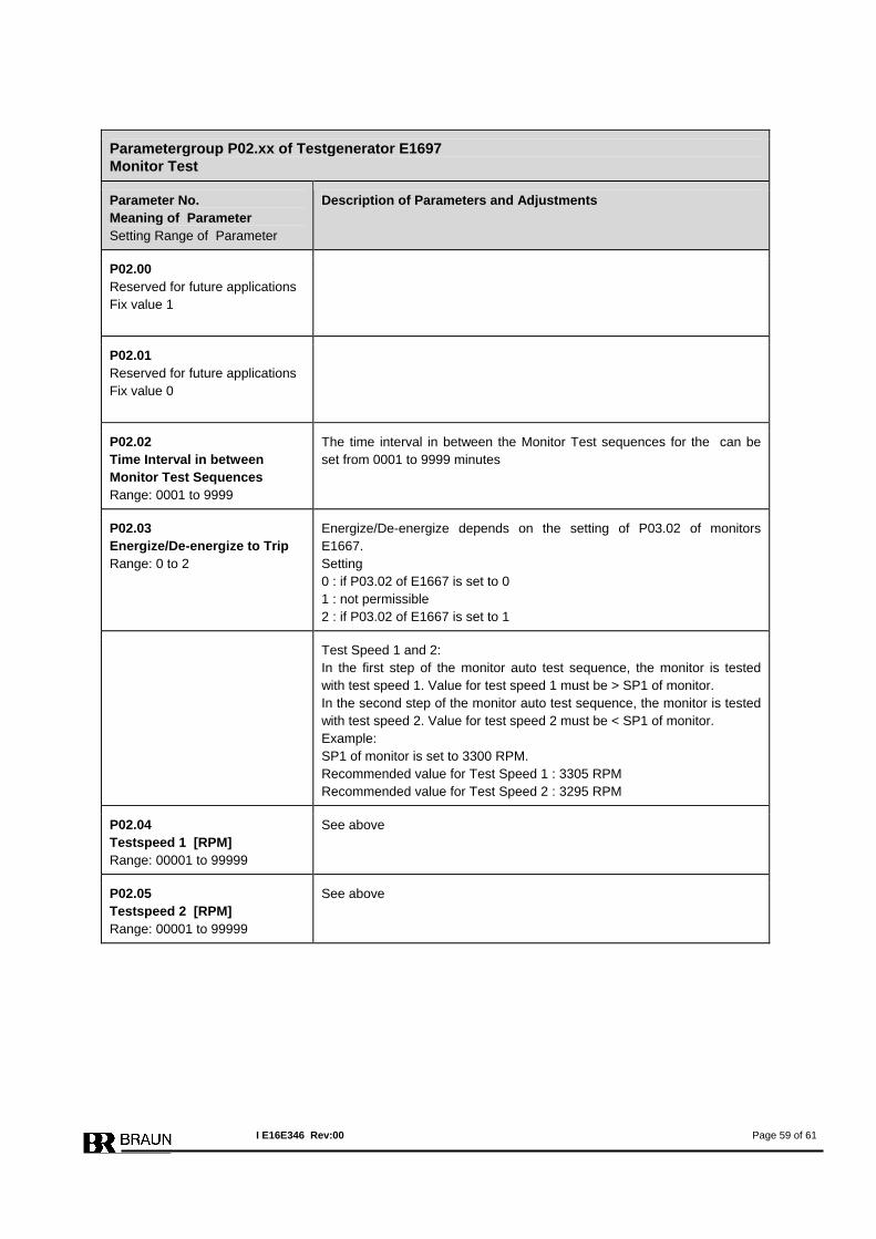
Parametergroup P02.xx of Testgenerator E1697 Monitor Test
Parameter No. Meaning of Parameter Setting Range of Parameter
Description of Parameters and Adjustments
P02.00 Reserved for future applications Fix value 1
P02.01 Reserved for future applications Fix value 0
P02.02 Time Interval in between Monitor Test Sequences Range: 0001 to 9999
The time interval in between the Monitor Test sequences for the can be set from 0001 to 9999 minutes
P02.03 Energize/De-energize to Trip Range: 0 to 2
Energize/De-energize depends on the setting of P03.02 of monitors E1667. Setting 0 : if P03.02 of E1667 is set to 0 1 : not permissible 2 : if P03.02 of E1667 is set to 1
Test Speed 1 and 2: In the first step of the monitor auto test sequence, the monitor is tested with test speed 1. Value for test speed 1 must be > SP1 of monitor. In the second step of the monitor auto test sequence, the monitor is tested with test speed 2. Value for test speed 2 must be < SP1 of monitor. Example: SP1 of monitor is set to 3300 RPM. Recommended value for Test Speed 1 : 3305 RPM Recommended value for Test Speed 2 : 3295 RPM
P02.04 Testspeed 1 [RPM] Range: 00001 to 99999
See above
P02.05 Testspeed 2 [RPM] Range: 00001 to 99999
See above
I E16E346 Rev:00 Page 59 of 61
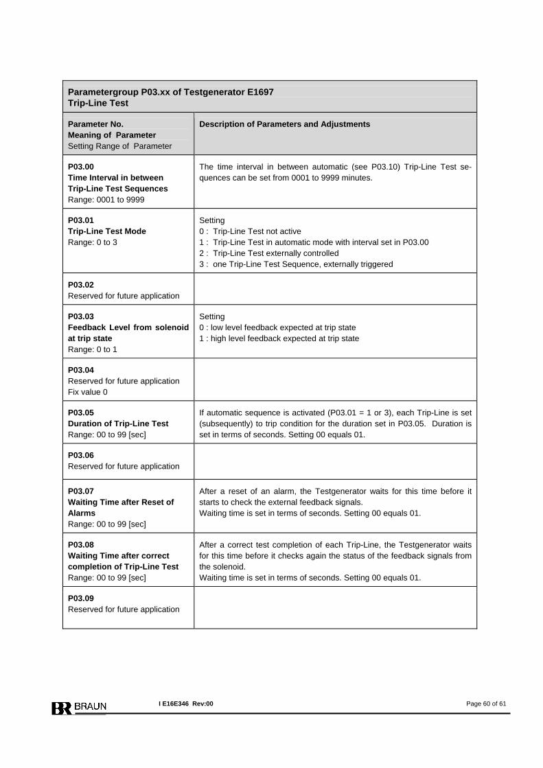
Parametergroup P03.xx of Testgenerator E1697 Trip-Line Test
Parameter No. Meaning of Parameter Setting Range of Parameter
Description of Parameters and Adjustments
P03.00 Time Interval in between Trip-Line Test Sequences Range: 0001 to 9999
The time interval in between automatic (see P03.10) Trip-Line Test se-quences can be set from 0001 to 9999 minutes.
P03.01 Trip-Line Test Mode Range: 0 to 3
Setting 0 : Trip-Line Test not active 1 : Trip-Line Test in automatic mode with interval set in P03.00 2 : Trip-Line Test externally controlled 3 : one Trip-Line Test Sequence, externally triggered
P03.02 Reserved for future application
P03.03 Feedback Level from solenoid at trip state Range: 0 to 1
Setting 0 : low level feedback expected at trip state 1 : high level feedback expected at trip state
P03.04 Reserved for future application Fix value 0
P03.05 Duration of Trip-Line Test Range: 00 to 99 [sec]
If automatic sequence is activated (P03.01 = 1 or 3), each Trip-Line is set (subsequently) to trip condition for the duration set in P03.05. Duration is set in terms of seconds. Setting 00 equals 01.
P03.06 Reserved for future application
P03.07 Waiting Time after Reset of Alarms Range: 00 to 99 [sec]
After a reset of an alarm, the Testgenerator waits for this time before it starts to check the external feedback signals. Waiting time is set in terms of seconds. Setting 00 equals 01.
P03.08 Waiting Time after correct completion of Trip-Line Test Range: 00 to 99 [sec]
After a correct test completion of each Trip-Line, the Testgenerator waits for this time before it checks again the status of the feedback signals from the solenoid. Waiting time is set in terms of seconds. Setting 00 equals 01.
P03.09 Reserved for future application
I E16E346 Rev:00 Page 60 of 61
Parametergroup P04.xx of Testgenerator E1697 PROFIBUS
Parameter No. Meaning of Parameter Setting Range of Parameter
Description of Parameters and Adjustments
P04.00 Device No for PROFIBUS Range: 001 to 125
All members of the PROFIBUS-Communication must have different device nos.
I E16E346 Rev:00 Page 61 of 61

![NRW-Bildreferenzkatalog - Private Abwasserleitungen...Bildreferenzkatalog „Private Abwasserleitungen“ Seite 1 Haarrisse Beschreibung gemäß DIN EN 13508-2 [2]: Ein Riss, der nur](https://img.pdfslide.org/doc/110x75/5f4516b0fd766d513857de75/nrw-bildreferenzkatalog-private-abwasserleitungen-bildreferenzkatalog-aprivate.jpg)