Embed Size (px)
Citation preview
Titelseite 210 mm
Bremsenkomponenten und BremssystemeBrake Components and Brake Systems
für Spezialserien und Nutzfahrzeugefor Special Series and Commercial Vehicles
SVB15
ATE – A Trademark of the Continental Corporation
Postfach 90 01 20 · D-60441 Frankfurt a. M. Tel. +49 (0) 69 7603-1 · Fax +49 (0) 69 761061
www.ate.de©20
15 C
ontin
enta
l Aft
erm
arke
t Gm
bH
Rückseite 210 mm
C3
Bremsen-Ersatzteilprogramm Brake Parts Program
2014ATE Classic
WK 6 Bremsen-Servicegeräteund Werkzeuge
Bitte fordern Sie unsere aktuellen Kataloge an.
Please ask for our current catalogues.
© 2015 Continental Aftermarket GmbH
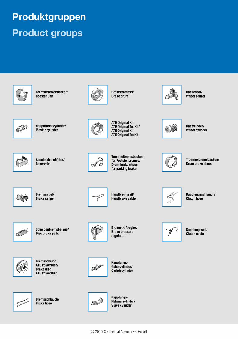
Radsensor/Wheel sensor
Radzylinder/Wheel cylinder
Kupplungsschlauch/Clutch hose
Kupplungs-Nehmerzylinder/Slave cylinder
Kupplungsseil/Clutch cable
Kupplungs-Geberzylinder/Clutch cylinder
Bremstrommel/Brake drum
Trommelbremsbackenfür Feststellbremse/Drum brake shoesfor parking brake
Handbremsseil/Handbrake cable
Bremskraftregler/Brake pressureregulator
ATE Original KitATE Original TopKit/ATE Original KitATE Original TopKit
Hauptbremszylinder/Master cylinder
Ausgleichsbehälter/Reservoir
BremsscheibeATE PowerDisc/Brake disc ATE PowerDisc
Bremsschlauch/Brake hose
Bremssattel/Brake caliper
Scheibenbremsbeläge/Disc brake pads
Bremskraftverstärker/Booster unit
Trommelbremsbacken/Drum brake shoes
Produktgruppen
Product groups
© 2015 Continental Aftermarket GmbH
3.Umschlagseite 210 mm1. Umschlagseite 210 mm
C3
Bremsen-Ersatzteilprogramm Brake Parts Program
2014ATE Classic
WK 6 Bremsen-Servicegeräteund Werkzeuge
Bitte fordern Sie unsere aktuellen Kataloge an.
Please ask for our current catalogues.
© 2015 Continental Aftermarket GmbH
Radsensor/Wheel sensor
Radzylinder/Wheel cylinder
Kupplungsschlauch/Clutch hose
Kupplungs-Nehmerzylinder/Slave cylinder
Kupplungsseil/Clutch cable
Kupplungs-Geberzylinder/Clutch cylinder
Bremstrommel/Brake drum
Trommelbremsbackenfür Feststellbremse/Drum brake shoesfor parking brake
Handbremsseil/Handbrake cable
Bremskraftregler/Brake pressureregulator
ATE Original KitATE Original TopKit/ATE Original KitATE Original TopKit
Hauptbremszylinder/Master cylinder
Ausgleichsbehälter/Reservoir
BremsscheibeATE PowerDisc/Brake disc ATE PowerDisc
Bremsschlauch/Brake hose
Bremssattel/Brake caliper
Scheibenbremsbeläge/Disc brake pads
Bremskraftverstärker/Booster unit
Trommelbremsbacken/Drum brake shoes
Produktgruppen
Product groups
© 2015 Continental Aftermarket GmbH
3.Umschlagseite 210 mm1. Umschlagseite 210 mm
1© 2015 Continental Aftermarket GmbH
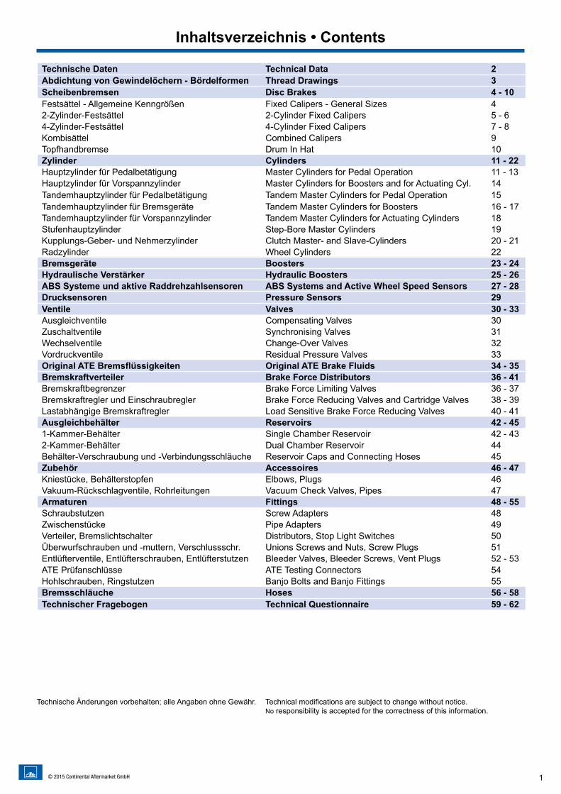
Technische Daten Technical Data 2Abdichtung von Gewindelöchern - Bördelformen Thread Drawings 3Scheibenbremsen Disc Brakes 4 - 10Festsättel - Allgemeine Kenngrößen Fixed Calipers - General Sizes 42-Zylinder-Festsättel 2-Cylinder Fixed Calipers 5 - 64-Zylinder-Festsättel 4-Cylinder Fixed Calipers 7 - 8Kombisättel Combined Calipers 9Topfhandbremse Drum In Hat 10Zylinder Cylinders 11 - 22Hauptzylinder für Pedalbetätigung Master Cylinders for Pedal Operation 11 - 13Hauptzylinder für Vorspannzylinder Master Cylinders for Boosters and for Actuating Cyl. 14Tandemhauptzylinder für Pedalbetätigung Tandem Master Cylinders for Pedal Operation 15Tandemhauptzylinder für Bremsgeräte Tandem Master Cylinders for Boosters 16 - 17Tandemhauptzylinder für Vorspannzylinder Tandem Master Cylinders for Actuating Cylinders 18Stufenhauptzylinder Step-Bore Master Cylinders 19Kupplungs-Geber- und Nehmerzylinder Clutch Master- and Slave-Cylinders 20 - 21Radzylinder Wheel Cylinders 22Bremsgeräte Boosters 23 - 24Hydraulische Verstärker Hydraulic Boosters 25 - 26ABS Systeme und aktive Raddrehzahlsensoren ABS Systems and Active Wheel Speed Sensors 27 - 28Drucksensoren Pressure Sensors 29Ventile Valves 30 - 33Ausgleichventile Compensating Valves 30Zuschaltventile Synchronising Valves 31Wechselventile Change-Over Valves 32Vordruckventile Residual Pressure Valves 33Original ATE Bremsflüssigkeiten Original ATE Brake Fluids 34 - 35Bremskraftverteiler Brake Force Distributors 36 - 41Bremskraftbegrenzer Brake Force Limiting Valves 36 - 37Bremskraftregler und Einschraubregler Brake Force Reducing Valves and Cartridge Valves 38 - 39Lastabhängige Bremskraftregler Load Sensitive Brake Force Reducing Valves 40 - 41Ausgleichbehälter Reservoirs 42 - 451-Kammer-Behälter Single Chamber Reservoir 42 - 432-Kammer-Behälter Dual Chamber Reservoir 44Behälter-Verschraubung und -Verbindungsschläuche Reservoir Caps and Connecting Hoses 45Zubehör Accessoires 46 - 47Kniestücke, Behälterstopfen Elbows, Plugs 46Vakuum-Rückschlagventile, Rohrleitungen Vacuum Check Valves, Pipes 47Armaturen Fittings 48 - 55Schraubstutzen Screw Adapters 48Zwischenstücke Pipe Adapters 49Verteiler, Bremslichtschalter Distributors, Stop Light Switches 50Überwurfschrauben und -muttern, Verschlussschr. Unions Screws and Nuts, Screw Plugs 51Entlüfterventile, Entlüfterschrauben, Entlüfterstutzen Bleeder Valves, Bleeder Screws, Vent Plugs 52 - 53ATE Prüfanschlüsse ATE Testing Connectors 54Hohlschrauben, Ringstutzen Banjo Bolts and Banjo Fittings 55Bremsschläuche Hoses 56 - 58Technischer Fragebogen Technical Questionnaire 59 - 62
Inhaltsverzeichnis • Contents
Technische Änderungen vorbehalten; alle Angaben ohne Gewähr. Technical modifications are subject to change without notice.No responsibility is accepted for the correctness of this information.
2 © 2015 Continental Aftermarket GmbH
Continental hat nur dafür einzustehen, dass die Liefergegenstände den von Continental Teves zur Verfügung gestellten Zeichnungen, Spezifikationen und sonstigen Daten entsprechen.
Der Besteller hingegen hat zu prüfen, ob die Liefergegenstände für den speziellen - vom Besteller vorgesehenen - Verwendungszweck geeignet sind.
Continental prüft für den vorgesehenen Verwendungszweck konstruktiv nur für den Fall, dass dies ausdrücklich zwischen Conti-nental Teves und dem Besteller vertraglich vereinbart ist und nur mit Hindblick auf die Angaben, die der Besteller für diese Prüfung macht.
Die Durchführung von Fahr- bzw. Betriebsversuchen sowie die Erteilung der technischen Freigabe des Liefergegenstandes mit Hin-blick auf den vom Besteller vorgesehenen Verwendungszweck ist in jedem Falle Sache des Bestellers.
Continental shall only be responsible that the delivered goods correspond to the drawings, specifications, and other data that were provided by Continental Teves.
The purchaser has to verify whether the delivered goods are suitable for the special purpose intended by the purchaser.
Continental have to check the planned purpose in the constructive way only in case Continental Teves and the purchaser agreed upon by contract and only according to the data provided by the purchaser for this examination.
The performance of driving and operating tests and the granting of technical approval for the supplied article with regard to the applica-tion intended by the customer is in any event the responsibility of the customer.
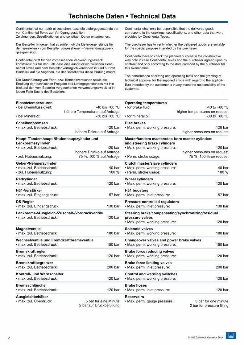
Technische Daten • Technical Data
Einsatztemperaturen• bei Bremsflüssigkeit: -40 bis +80 °C höhere Temperaturen auf Anfrage• bei Mineralöl: -30 bis +80 °C
Scheibenbremsen• max. zul. Betriebsdruck: 120 bar höhere Drücke auf Anfrage Haupt-/Tandemhaupt-/Stufenhauptzylinder und Lenkbremszylinder • max. zul. Betriebsdruck: 120 bar höhere Drücke auf Anfrage• zul. Hubausnutzung: 75 %, 100 % auf Anfrage Geber-/Nehmerzylinder • max. zul. Betriebsdruck: 40 bar• zul. Hubausnutzung: 100 % Radzylinder • max. zul. Betriebsdruck: 120 bar H31-Verstärker • max. zul. Eingangsdruck: 57 bar DS-Regler • max. zul. Eingangsdruck: 130 bar Lenkbrems-/Ausgleich-/Zuschalt-/Vordruckventile • max. zul. Betriebsdruck: 120 bar
Magnetventile • max. zul. Betriebsdruck: 180 bar Wechselventile und Fremdkraftbremsventile • max. zul. Betriebsdruck: 150 bar Bremskraftregler • max. zul. Betriebsdruck: 120 bar Bremskraftbegrenzer • max. zul. Betriebsdruck: 200 bar Kontroll- und Warnschalter • max. zul. Betriebsdruck: 120 bar Bremsschläuche • max. zul. Betriebsdruck: 120 bar Ausgleichbehälter • max. zul. Überdruck: 5 bar für eine Minute 2 bar zur Druckbefüllung
Operating temperatures • for brake fluid: -40 to +80 °C higher temperatures on request• for mineral oil: -30 to +80 °C Disc brakes • Max. perm. working pressure: 120 bar higher pressures on request Master/tandem master/step-bore master cylinders and steering brake cylinders • Max. perm. working pressure: 120 bar higher pressures on request• Perm. stroke usage: 75 %, 100 % on request Clutch master/slave cylinders • Max. perm. working pressure: 40 bar• Perm. stroke usage: 100 % Wheel cylinders • Max. perm. working pressure: 120 bar H31 boosters • Max. perm. inlet pressure: 57 bar Pressure-controlled regulators • Max. perm. inlet pressure: 130 bar Steering brake/compensating/synchronizing/residual pressure valves • Max. perm. working pressure: 120 bar Solenoid valves • Max. perm. working pressure: 180 bar Changeover valves and power brake valves • Max. perm. working pressure: 150 bar Brake force reducing valves • Max. perm. working pressure: 120 bar Brake force limiting valves • Max. perm. inlet pressure: 200 bar Control and warning switches • Max. perm. working pressure: 120 bar Brake hoses • Max. perm. inlet pressure: 120 bar Reservoirs • Max. perm. gauge pressure: 5 bar for one minute 2 bar for pressure filling
3© 2015 Continental Aftermarket GmbH
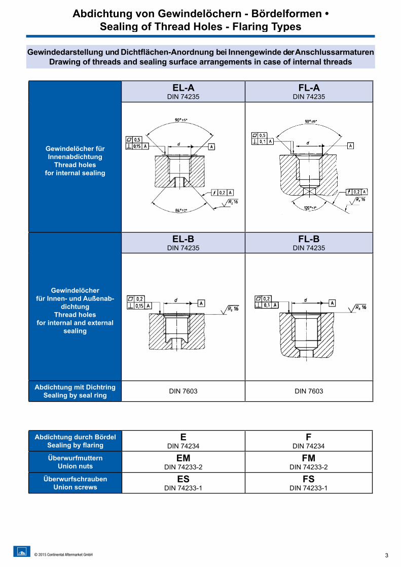
Gewindedarstellung und Dichtflächen-Anordnung bei Innengewinde der Anschlussarmaturen Drawing of threads and sealing surface arrangements in case of internal threads
Gewindelöcher für Innenabdichtung
Thread holes for internal sealing
EL-ADIN 74235
FL-ADIN 74235
Gewindelöcher für Innen- und Außenab-
dichtungThread holes
for internal and external sealing
EL-BDIN 74235
FL-BDIN 74235
Abdichtung mit DichtringSealing by seal ring DIN 7603 DIN 7603
Abdichtung von Gewindelöchern - Bördelformen • Sealing of Thread Holes - Flaring Types
Abdichtung durch Bördel Sealing by flaring
EDIN 74234
FDIN 74234
ÜberwurfmutternUnion nuts
EMDIN 74233-2
FMDIN 74233-2
ÜberwurfschraubenUnion screws
ESDIN 74233-1
FSDIN 74233-1
4 © 2015 Continental Aftermarket GmbH
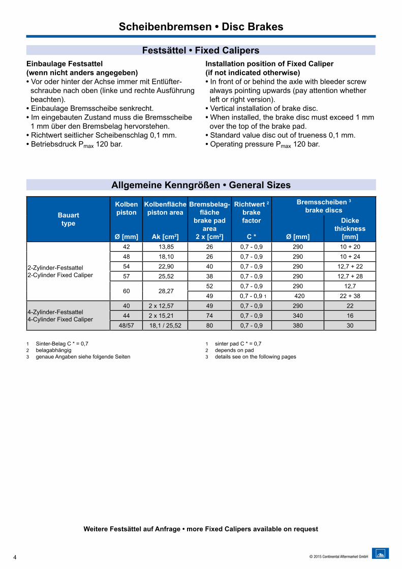
Festsättel • Fixed CalipersEinbaulage Festsattel (wenn nicht anders angegeben)• Vor oder hinter der Achse immer mit Entlüfter-
schraube nach oben (linke und rechte Ausführung beachten).
• Einbaulage Bremsscheibe senkrecht. • Im eingebauten Zustand muss die Bremsscheibe
1 mm über den Bremsbelag hervorstehen. • Richtwert seitlicher Scheibenschlag 0,1 mm.• Betriebsdruck Pmax 120 bar.
Installation position of Fixed Caliper(if not indicated otherwise)• In front of or behind the axle with bleeder screw
always pointing upwards (pay attention whether left or right version).
• Vertical installation of brake disc. • When installed, the brake disc must exceed 1 mm
over the top of the brake pad. • Standard value disc out of trueness 0,1 mm.• Operating pressure Pmax 120 bar.
Allgemeine Kenngrößen • General Sizes
Bauarttype
Kolbenpiston
Ø [mm]
Kolbenflächepiston area
Ak [cm2]
Bremsbelag-fläche
brake padarea
2 x [cm2]
Richtwert 2
brake factor
C *
Bremsscheiben 3
brake discs
Ø [mm]
Dickethickness
[mm]
2-Zylinder-Festsattel2-Cylinder Fixed Caliper
42 13,85 26 0,7 - 0,9 290 10 + 2048 18,10 26 0,7 - 0,9 290 10 + 2454 22,90 40 0,7 - 0,9 290 12,7 + 2257 25,52 38 0,7 - 0,9 290 12,7 + 28
60 28,2752 0,7 - 0,9 290 12,749 0,7 - 0,9 1 420 22 + 38
4-Zylinder-Festsattel4-Cylinder Fixed Caliper
40 2 x 12,57 49 0,7 - 0,9 290 2244 2 x 15,21 74 0,7 - 0,9 340 16
48/57 18,1 / 25,52 80 0,7 - 0,9 380 30
1 Sinter-Belag C * = 0,72 belagabhängig3 genaue Angaben siehe folgende Seiten
1 sinter pad C * = 0,72 depends on pad3 details see on the following pages
Weitere Festsättel auf Anfrage • more Fixed Calipers available on request
Scheibenbremsen • Disc Brakes
5© 2015 Continental Aftermarket GmbH
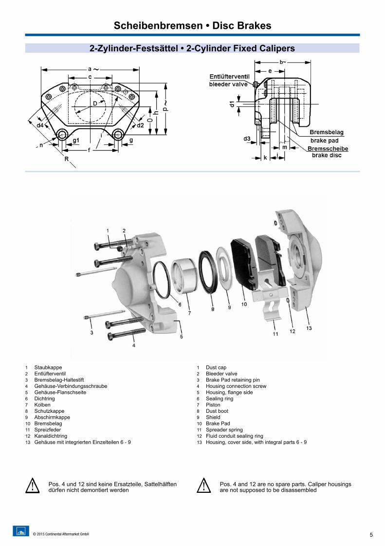
2-Zylinder-Festsättel • 2-Cylinder Fixed Calipers
1 Staubkappe2 Entlüfterventil3 Bremsbelag-Haltestift4 Gehäuse-Verbindungsschraube5 Gehäuse-Flanschseite6 Dichtring7 Kolben8 Schutzkappe9 Abschirmkappe10 Bremsbelag11 Spreizfeder12 Kanaldichtring13 Gehäuse mit integrierten Einzelteilen 6 - 9
1 Dust cap 2 Bleeder valve 3 Brake Pad retaining pin 4 Housing connection screw 5 Housing, flange side 6 Sealing ring 7 Piston 8 Dust boot 9 Shield 10 Brake Pad 11 Spreader spring 12 Fluid conduit sealing ring 13 Housing, cover side, with integral parts 6 - 9
Scheibenbremsen • Disc Brakes
Pos. 4 und 12 sind keine Ersatzteile, Sattelhälften dürfen nicht demontiert werden
Pos. 4 and 12 are no spare parts. Caliper housings are not supposed to be disassembled
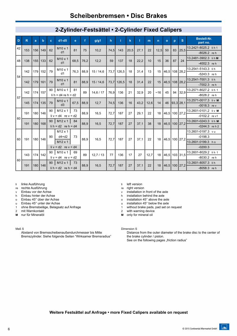
6 © 2015 Continental Aftermarket GmbH
li linke Ausführungre rechte Ausführungv Einbau vor der Achseh Einbau hinter der Achseo Einbau 45° über der Achseu Einbau 45° unter der Achse1 ohne Bremsbeläge, Belagsatz auf Anfrage2 mit WarnkontaktM nur für Mineralöl
Maß S Abstand von Bremsscheibenaußendurchmesser bis Mitte
Bremszylinder. Siehe folgende Seiten “Wirksamer Bremsradius”
li left versionre right versionv installation in front of the axleh installation behind the axleo installation 45° above the axleu installation 45° below the axle1 without brake pads, pad set on request2 with warning deviceM only for mineral oil
Dimension S Distance from the outer diameter of the brake disc to the center of the brake cylinder / piston. See on the following pages „friction radius”
2-Zylinder-Festsättel • 2-Cylinder Fixed Calipers
D R a b c d1-d5 e f g/g1 h i k l m n o p S Bestell-Nr.part no.
42 153 156 149 62 M10 x 1d1 81 75 10,2 74,5 143 20,5 27,1 22 12,5 50 83 25,5
13.2421-8025.2 li h 1
-8026.2 re h
48 138 155 133 62 M10 x 1d1 68,5 76,2 12,2 59 137 18 22,2 10 15 36 87 24
13.2481-3902.3 li h M
-4002.3 re h
54142 179 152 79 M10 x 1
d1 76,3 88,9 15 / 14,6 73,7 126,5 18 31,4 13 15 46,5 108 28,213.2541-5143.3 li h
-5243.3 re h
142 179 161 79 M10 x 1d1 81 88,9 15 / 14,6 73,7 126,5 18 31,4 22 15 46,5 108 28,2
13.2541-7001.3 li h
-7002.3 re h
57142 174 157
90 M10 x 1 8189 14,6 / 17 76,9 136 21 32,9 20 ~16 45 94 32,9
13.2571-8027.2 li h 1
li h = d4 re h = d2 -8028.2 re h
145 174 135 79 M10 x 1d3 67,5 88,9 12,7 74,5 136 16 43,2 12,6 14 46 93,3 28,1
13.2571-0017.3 li v M
-0018.3 re v
60191 180 146
90 M12 x 1 7388,9 16,5 72,7 187 27 29,1 22 18 46,5 100 27,2
13.2601-0101.2 li v M
li v = d4 re v = d2 -0102.2 re v 1
191 180 16890 M12 x 1 84
88,9 16,5 72,7 187 27 37,1 38 18 46,5 100 27,213.2601-0243.3 li h M
li h = d2 re h = d4 -0244.3 re h 2
60 191 180 14690
M12 x 173
88,9 16,5 72,7 187 27 37,1 22 18 46,5 100 27,2
13.2601-0197.3 v u
d4+d2 -0198.3M12 x 1 13.2601.0199.3 h o
li v = d2 re v = d4 -0200.3
60
143 174 14290 M10 x 1 69
89 12,7 / 13 77 136 17 27 12,7 18 46,5 103 31,513.2601-8029.2 li h 1
li v = d4 re v = d2 -8030.2 re h
191 180 14690 M12 x 1 73
88,9 16,5 72,7 187 27 37,1 22 18 46,5 100 27,213.2601-8057.3 li h
li h = d2 re h = d4 -8058.3 re h
Weitere Festsättel auf Anfrage • more Fixed Calipers available on request
Scheibenbremsen • Disc Brakes
7© 2015 Continental Aftermarket GmbH
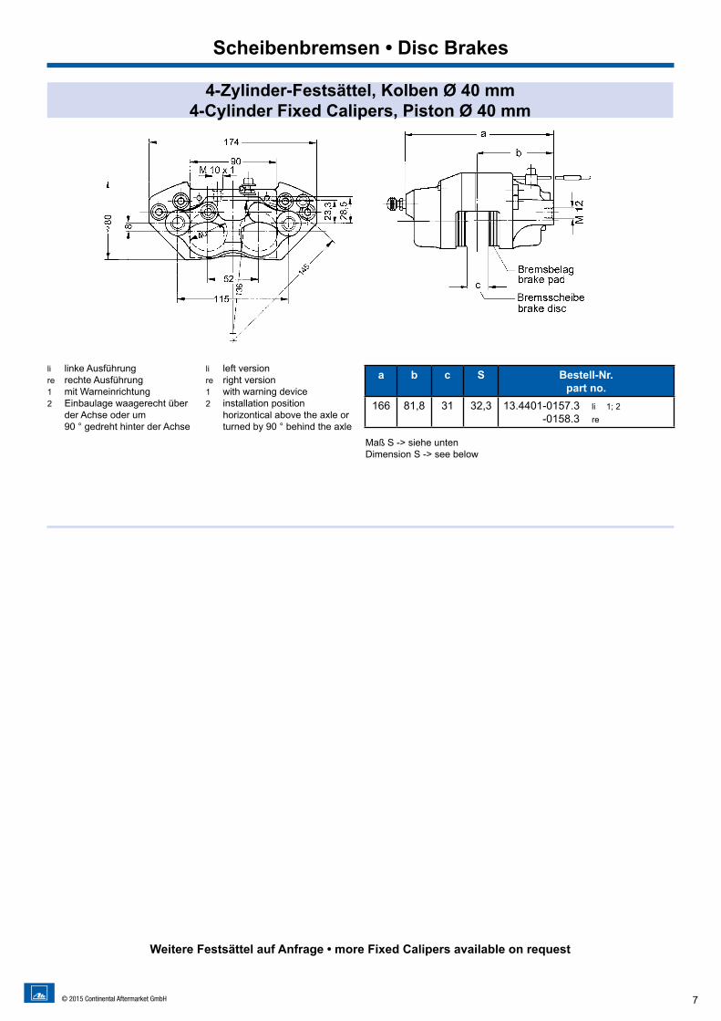
Scheibenbremsen • Disc Brakes4-Zylinder-Festsättel, Kolben Ø 40 mm
4-Cylinder Fixed Calipers, Piston Ø 40 mm
li linke Ausführungre rechte Ausführung1 mit Warneinrichtung2 Einbaulage waagerecht über
der Achse oder um 90 ° gedreht hinter der Achse
li left versionre right version1 with warning device2 installation position
horizontical above the axle or turned by 90 ° behind the axle
a b c S Bestell-Nr.part no.
166 81,8 31 32,3 13.4401-0157.3 li 1; 2 -0158.3 re
Weitere Festsättel auf Anfrage • more Fixed Calipers available on request
Maß S -> siehe untenDimension S -> see below
Scheibenbremsen • Disc Brakes

4-Zylinder-Festsättel, Kolben Ø 44 mm • 4-Cylinder Fixed Calipers, Piston Ø 44 mm
S Bestell-Nr.part no.
3313.4441-8017.2 li 1
-8018.2 re
3313.4441-8015.2 li 2
-8016.2 re
li linke Ausführungre rechte Ausführung1 1-Kreis-Anschluss2 2-Kreis-Anschluss
li left versionre right version1 single circuit connection2 dual circuit connection
Maß S -> siehe untenDimension S -> see below
Wirksamer Bremsradius (Rw) • Friction Radius (Rw)
DA BremsscheibenaußendurchmesserS Abstand von Bremsscheibenaußendurchmesser bis Mitte
Bremszylinder (Bremskolben)
DA outer diameter of brake disc S distance from the outer diameter of the brake disc to the center
of the brake cylinder / piston
Scheibenbremsen • Disc Brakes
Weitere Festsättel auf Anfrage • more Fixed Calipers available on request
8 © 2015 Continental Aftermarket GmbH
9
Kombisättel • Combined Calipers
Weitere Informationen auf Anfrage • more information on request
Scheibenbremsen • Disc Brakes
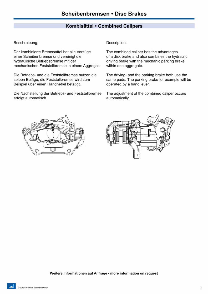
Beschreibung:
Der kombinierte Bremssattel hat alle Vorzüge einer Scheibenbremse und vereinigt diehydraulische Betriebsbremse mit der mechanischen Feststellbremse in einem Aggregat.
Die Betriebs- und die Feststellbremse nutzen die selben Beläge, die Feststellbremse wird zum Beispiel über einen Handhebel betätigt.
Die Nachstellung der Betriebs- und Feststellbremseerfolgt automatisch.
Description:
The combined caliper has the advantagesof a disk brake and also combines the hydraulicdriving brake with the mechanic parking brakewithin one aggregate.
The driving- and the parking brake both use the same pads. The parking brake for example will be operated by a hand lever.
The adjustment of the combined caliper occurs automatically.
© 2015 Continental Aftermarket GmbH
10 © 2015 Continental Aftermarket GmbH
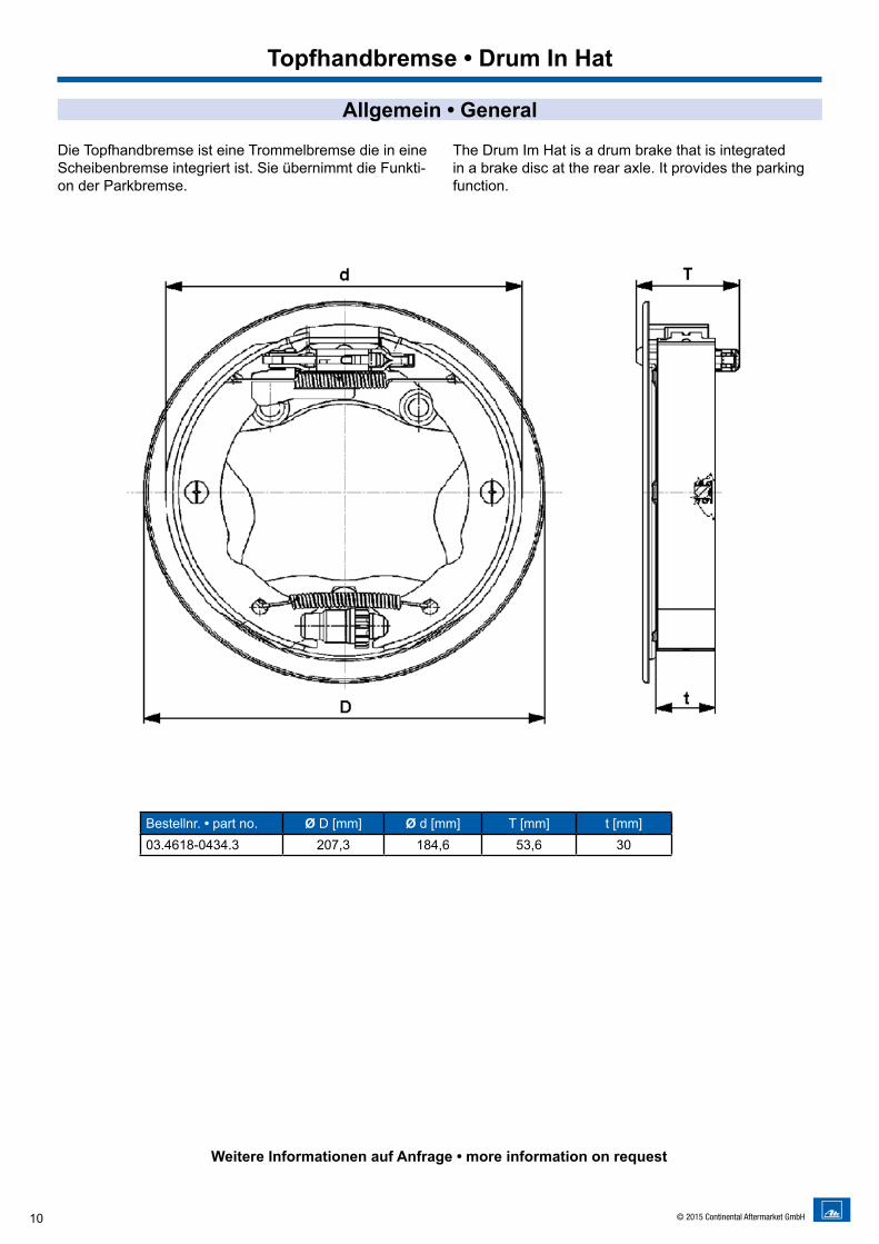
Topfhandbremse • Drum In Hat
Bestellnr. • part no. Ø D [mm] Ø d [mm] T [mm] t [mm]03.4618-0434.3 207,3 184,6 53,6 30
Die Topfhandbremse ist eine Trommelbremse die in eine Scheibenbremse integriert ist. Sie übernimmt die Funkti-on der Parkbremse.
The Drum Im Hat is a drum brake that is integrated in a brake disc at the rear axle. It provides the parking function.
Allgemein • General
Weitere Informationen auf Anfrage • more information on request
11© 2015 Continental Aftermarket GmbH
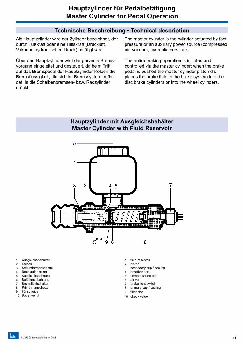
Als Hauptzylinder wird der Zylinder bezeichnet, der durch Fußkraft oder eine Hilfskraft (Druckluft, Vakuum, hydraulischen Druck) betätigt wird.
Über den Hauptzylinder wird der gesamte Brems-vorgang eingeleitet und gesteuert, da beim Tritt auf das Bremspedal der Hauptzylinder-Kolben die Bremsflüssigkeit, die sich im Bremssystem befin-det, in die Scheibenbremsen- bzw. Radzylinder drückt.
The master cylinder is the cylinder actuated by foot pressure or an auxiliary power source (compressed air, vacuum, hydraulic pressure).
The entire braking operation is initiated and controlled via the master cylinder; when the brake pedal is pushed the master cylinder piston dis-places the brake fluid in the brake system into the disc brake cylinders or into the wheel cylinders.
Technische Beschreibung • Technical description
Hauptzylinder mit AusgleichsbehälterMaster Cylinder with Fluid Reservoir
1 Ausgleichsbehälter2 Kolben3 Sekundärmanschette4 Nachlaufbohrung5 Ausgleichsbohrung6 Belüftungsbohrung7 Bremslichtschalter8 Primärmanschette9 Füllscheibe10 Bodenventil
1 fluid reservoir2 piston3 secondary cup / sealing4 breather port5 compensating port6 air vent7 brake light switch8 primary cup / sealing9 filler disc10 check value
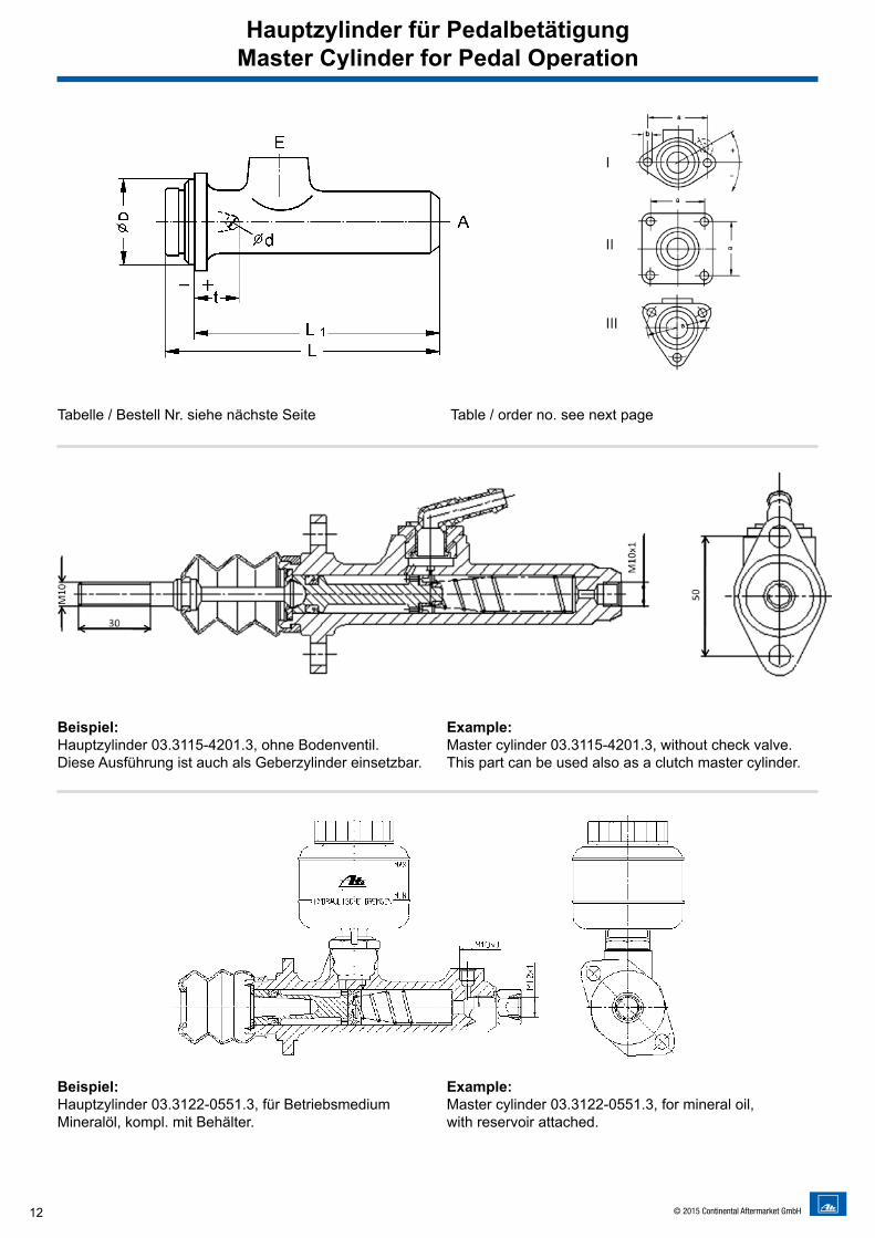
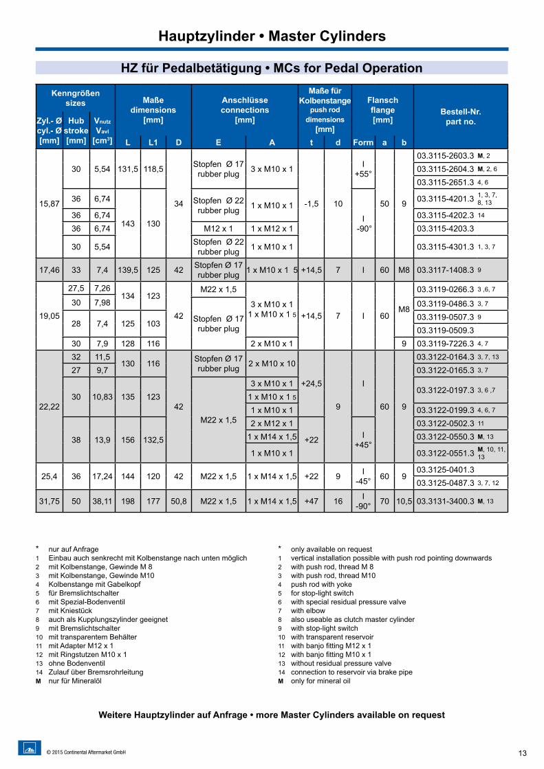
Hauptzylinder für PedalbetätigungMaster Cylinder for Pedal Operation
12 © 2015 Continental Aftermarket GmbH
Tabelle / Bestell Nr. siehe nächste Seite Table / order no. see next page
Beispiel:Hauptzylinder 03.3115-4201.3, ohne Bodenventil. Diese Ausführung ist auch als Geberzylinder einsetzbar.
Example:Master cylinder 03.3115-4201.3, without check valve. This part can be used also as a clutch master cylinder.
Beispiel: Hauptzylinder 03.3122-0551.3, für Betriebsmedium Mineralöl, kompl. mit Behälter.
Example: Master cylinder 03.3122-0551.3, for mineral oil, with reservoir attached.
Hauptzylinder für PedalbetätigungMaster Cylinder for Pedal Operation
13© 2015 Continental Aftermarket GmbH
* nur auf Anfrage 1 Einbau auch senkrecht mit Kolbenstange nach unten möglich 2 mit Kolbenstange, Gewinde M 8 3 mit Kolbenstange, Gewinde M10 4 Kolbenstange mit Gabelkopf 5 für Bremslichtschalter 6 mit Spezial-Bodenventil 7 mit Kniestück 8 auch als Kupplungszylinder geeignet 9 mit Bremslichtschalter 10 mit transparentem Behälter 11 mit Adapter M12 x 1 12 mit Ringstutzen M10 x 1 13 ohne Bodenventil14 Zulauf über Bremsrohrleitung M nur für Mineralöl
* only available on request1 vertical installation possible with push rod pointing downwards2 with push rod, thread M 83 with push rod, thread M104 push rod with yoke5 for stop-light switch6 with special residual pressure valve7 with elbow8 also useable as clutch master cylinder9 with stop-light switch10 with transparent reservoir11 with banjo fitting M12 x 112 with banjo fitting M10 x 113 without residual pressure valve14 connection to reservoir via brake pipeM only for mineral oil
Weitere Hauptzylinder auf Anfrage • more Master Cylinders available on request
HZ für Pedalbetätigung • MCs for Pedal Operation
Kenngrößensizes Maße
dimensions [mm]
Anschlüsseconnections
[mm]
Maße fürKolbenstange
push rod dimensions
[mm]
Flanschflange[mm]
Bestell-Nr.part no.Zyl.- Ø
cyl.- Ø [mm]
Hubstroke[mm]
Vnutz
Vavl
[cm3] L L1 D E A t d Form a b
15,87
30 5,54 131,5 118,5
34
Stopfen Ø 17rubber plug 3 x M10 x 1
-1,5 10
I+55°
50 9
03.3115-2603.3 M, 2
03.3115-2604.3 M, 2, 6
03.3115-2651.3 4, 6
36 6,74
143 130
Stopfen Ø 22rubber plug 1 x M10 x 1
I -90°
03.3115-4201.3 1, 3, 7, 8, 13
36 6,74 03.3115-4202.3 14
36 6,74 M12 x 1 1 x M12 x 1 03.3115-4203.3
30 5,54 Stopfen Ø 22rubber plug 1 x M10 x 1 03.3115-4301.3 1, 3, 7
17,46 33 7,4 139,5 125 42 Stopfen Ø 17 rubber plug 1 x M10 x 1 5 +14,5 7 I 60 M8 03.3117-1408.3 9
19,05
27,5 7,26134 123
42
M22 x 1,5
3 x M10 x 11 x M10 x 1 5 +14,5 7 I 60
M8
03.3119-0266.3 3 ,6, 7
30 7,98
Stopfen Ø 17rubber plug
03.3119-0486.3 3, 7
28 7,4 125 10303.3119-0507.3 9
03.3119-0509.330 7,9 128 116 2 x M10 x 1 9 03.3119-7226.3 4, 7
22,22
32 11,5130 116
42
Stopfen Ø 17rubber plug 2 x M10 x 10
+24,5
9
I
60 9
03.3122-0164.3 3, 7, 13
27 9,7 03.3122-0165.3 3, 7
30 10,83 135 123
M22 x 1,5
3 x M10 x 103.3122-0197.3 3, 6 ,7
1 x M10 x 1 51 x M10 x 1 03.3122-0199.3 4, 6, 7
38 13,9 156 132,5
2 x M12 x 1
+22 I+45°
03.3122-0502.3 11
1 x M14 x 1,5 03.3122-0550.3 M, 13
1 x M10 x 1 03.3122-0551.3 M, 10, 11, 13
25,4 36 17,24 144 120 42 M22 x 1,5 1 x M14 x 1,5 +22 9 I-45° 60 9
03.3125-0401.303.3125-0487.3 3, 7, 12
31,75 50 38,11 198 177 50,8 M22 x 1,5 1 x M14 x 1,5 +47 16 I-90° 70 10,5 03.3131-3400.3 M, 13
Hauptzylinder • Master Cylinders
14 © 2015 Continental Aftermarket GmbH
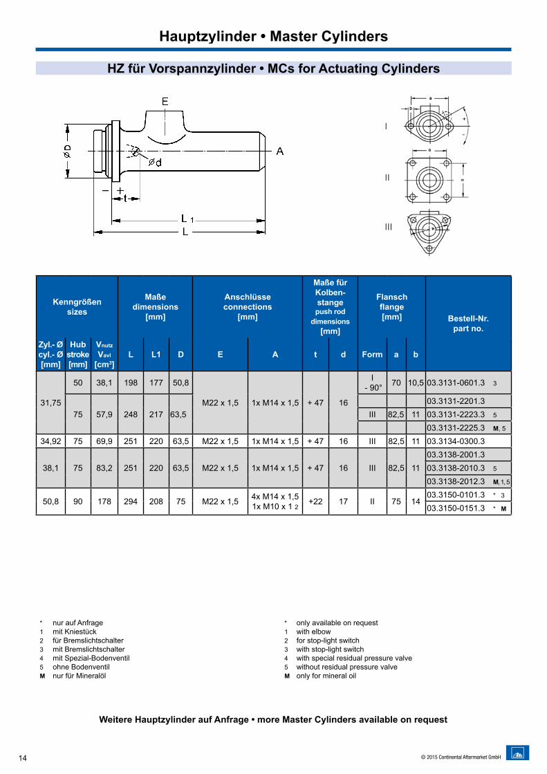
HZ für Vorspannzylinder • MCs for Actuating Cylinders
* nur auf Anfrage1 mit Kniestück2 für Bremslichtschalter3 mit Bremslichtschalter4 mit Spezial-Bodenventil5 ohne BodenventilM nur für Mineralöl
* only available on request 1 with elbow2 for stop-light switch3 with stop-light switch4 with special residual pressure valve5 without residual pressure valveM only for mineral oil
Hauptzylinder • Master Cylinders
Kenngrößensizes
Maßedimensions
[mm]
Anschlüsseconnections
[mm]
Maße fürKolben- stangepush rod
dimensions[mm]
Flanschflange[mm] Bestell-Nr.
part no.
Zyl.- Øcyl.- Ø [mm]
Hubstroke[mm]
Vnutz
Vavl
[cm3]L L1 D E A t d Form a b
31,75
50 38,1 198 177 50,8
M22 x 1,5 1x M14 x 1,5 + 47 16
I - 90° 70 10,5 03.3131-0601.3 3
75 57,9 248 217 63,503.3131-2201.3
III 82,5 11 03.3131-2223.3 5
03.3131-2225.3 M, 5
34,92 75 69,9 251 220 63,5 M22 x 1,5 1x M14 x 1,5 + 47 16 III 82,5 11 03.3134-0300.3
38,1 75 83,2 251 220 63,5 M22 x 1,5 1x M14 x 1,5 + 47 16 III 82,5 1103.3138-2001.303.3138-2010.3 5
03.3138-2012.3 M, 1, 5
50,8 90 178 294 208 75 M22 x 1,5 4x M14 x 1,51x M10 x 1 2 +22 17 II 75 14
03.3150-0101.3 * 3
03.3150-0151.3 * M
Weitere Hauptzylinder auf Anfrage • more Master Cylinders available on request
15© 2015 Continental Aftermarket GmbH
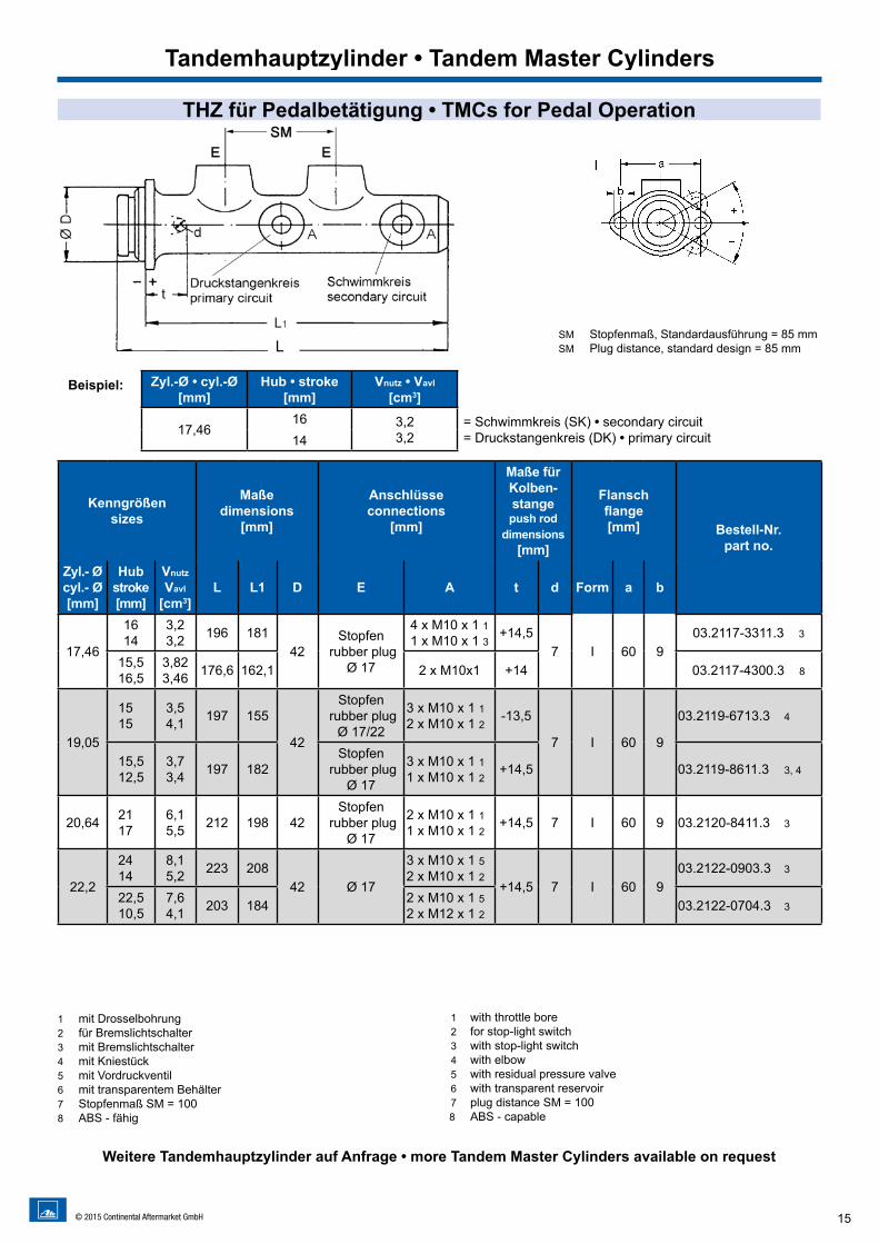
THZ für Pedalbetätigung • TMCs for Pedal Operation
SM Stopfenmaß, Standardausführung = 85 mmSM Plug distance, standard design = 85 mm
Kenngrößensizes
Maßedimensions
[mm]
Anschlüsseconnections
[mm]
Maße fürKolben- stangepush rod
dimensions[mm]
Flanschflange[mm] Bestell-Nr.
part no.
Zyl.- Øcyl.- Ø [mm]
Hubstroke[mm]
Vnutz
Vavl
[cm3]L L1 D E A t d Form a b
17,46
1614
3,23,2 196 181
42Stopfen
rubber plug Ø 17
4 x M10 x 1 11 x M10 x 1 3 +14,5
7 I 60 903.2117-3311.3 3
15,516,5
3,82 3,46 176,6 162,1 2 x M10x1 +14 03.2117-4300.3 8
19,05
1515
3,54,1 197 155
42
Stopfen rubber plug
Ø 17/22
3 x M10 x 1 12 x M10 x 1 2 -13,5
7 I 60 9
03.2119-6713.3 4
15,512,5
3,73,4 197 182
Stopfen rubber plug
Ø 17
3 x M10 x 1 11 x M10 x 1 2 +14,5 03.2119-8611.3 3, 4
20,64 2117
6,15,5 212 198 42
Stopfen rubber plug
Ø 17
2 x M10 x 1 11 x M10 x 1 2 +14,5 7 I 60 9 03.2120-8411.3 3
22,2
2414
8,15,2 223 208
42 Ø 17
3 x M10 x 1 52 x M10 x 1 2
+14,5 7 I 60 903.2122-0903.3 3
22,510,5
7,64,1 203 184 2 x M10 x 1 5
2 x M12 x 1 2 03.2122-0704.3 3
Zyl.-Ø • cyl.-Ø [mm]
Hub • stroke[mm]
Vnutz • Vavl
[cm3]L
17,4616 3,2
3,2= Schwimmkreis (SK) • secondary circuit= Druckstangenkreis (DK) • primary circuit14
1 mit Drosselbohrung2 für Bremslichtschalter3 mit Bremslichtschalter4 mit Kniestück5 mit Vordruckventil6 mit transparentem Behälter7 Stopfenmaß SM = 1008 ABS - fähig
1 with throttle bore2 for stop-light switch3 with stop-light switch4 with elbow5 with residual pressure valve6 with transparent reservoir7 plug distance SM = 1008 ABS - capable
Weitere Tandemhauptzylinder auf Anfrage • more Tandem Master Cylinders available on request
Tandemhauptzylinder • Tandem Master Cylinders
Beispiel:
L
16 © 2015 Continental Aftermarket GmbH
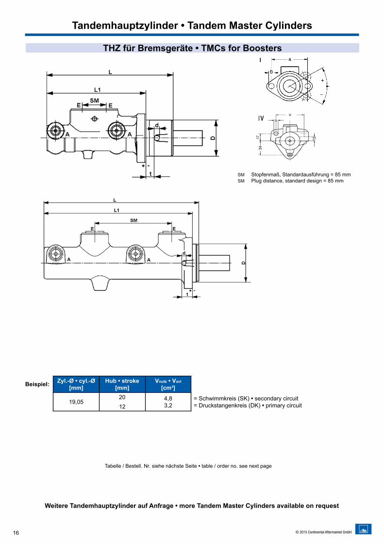
THZ für Bremsgeräte • TMCs for Boosters
SM Stopfenmaß, Standardausführung = 85 mmSM Plug distance, standard design = 85 mm
Tandemhauptzylinder • Tandem Master Cylinders
Zyl.-Ø • cyl.-Ø [mm]
Hub • stroke[mm]
Vnutz • Vavl
[cm3]
19,0520 4,8
3,2= Schwimmkreis (SK) • secondary circuit= Druckstangenkreis (DK) • primary circuit12
Beispiel:
Tabelle / Bestell. Nr. siehe nächste Seite • table / order no. see next page
Weitere Tandemhauptzylinder auf Anfrage • more Tandem Master Cylinders available on request
17© 2015 Continental Aftermarket GmbH
THZ für Bremsgeräte • TMCs for Boosters
Kenngrößensizes
Maßedimensions
[mm]
Anschlüsseconnections
[mm]
Maße fürKolben- stangepush rod
dimensions[mm]
Flanschflange[mm] Bestell-Nr.
part no.
Zyl.- Øcyl.-Ø [mm]
Hubstroke[mm]
Vnutz
Vavl
[cm3]L L1 D E A t d Form a b
19,05 2012
4,83,2 181,3 162,5 42
Stopfen rubber plug
Ø 173 x M10 x 1 2 +0,5 7,1 I 60 9 03.2119-6207.3
20,64
2313
6,84,2 185,8 167
42
Stopfen rubber plug
Ø 22
3 x M10 x 1 2 +0,5
7,1 I 60 9
03.2120-1142.3
1614
4,44,4 147 114,2
4 x M10 x 1 2 -22,303.2120-2031.3 6
1618
5,25,2 146 110 03.2120-3943.3 3
16,510
4,63,1 181,3 162,5
Stopfen rubber plug
Ø 173 x M10 x 1 2 +0,5 03.2120-4504.3
22,2
16,510
5,53,7 175,5 157,5
42
Stopfen rubber plug
Ø 173 x M10 x 1 2
+0,57,1 I 60 9
03.2122-0142.3
1816
6,16,1 184,5 166 Stopfen
rubber plug Ø 22
2 x M10 x 1 2 03.2122-6912.3
1917
6,36,4 139,7 103,7 4 x M10 x 1 2 -22,3 03.2122-9612.3 6
23,81
1913
7,35,4 178,2 159,7
42Stopfen
rubber plug Ø 22
2 x M10 x 1 21 x M10 x 1 3
+0,5 7,1 I 60 9
03.2123-0291.3
2410
9,55,2 193,5 175 2 x M10 x 1 2 03.2123-6002.3
1917
7,47,4 184,5 166 4 x M10 x 1 2 03.2123-8512.3
25,4
1715
7,27,2 178,3 159,5
42
Stopfen rubber plug
Ø 172 x M12 x 1 1
+0,5 7,1 I 60 9
03.2125-1302.3
2313
10,56,4 173,5 155
Stopfen rubber plug
Ø 222 x M10 x 1 2 03.2125-1902.3
26,99 1917
9,69,5 173,5 155 42
Stopfen rubber plug
Ø 22
2 x M10 x 1 2+0,5 7,1 I 60 9
03.2126-0511.3 4
2 x M10 x 1 2 03.2126-0512.3
30 2822
17,915,3 223 204,5 46
Stopfen rubber plug
Ø 22
1 x M10 x 1 21 x M14 x 1,5 2 +0,5 7,1 IV 58,9 9 03.2130-0102.3 5
1 mit Vordruckventil2 mit Drosselbohrung3 für Bremslichtschalter4 nur für hydr. Verstärker H315 nur für Vakuumverstärker6 Kompaktbauweise7 ABS/ESC - fähig8 Zentralventil
1 with residual pressure valve2 with restrictor bore3 for stop-light switch4 only for booster H315 only for vacuum booster 6 compact design7 ABS/ESC - capable8 central valve
Weitere Tandemhauptzylinder auf Anfrage • more Tandem Master Cylinders available on request
Tandemhauptzylinder • Tandem Master Cylinders

18 © 2015 Continental Aftermarket GmbH
THZ für Vorspannzylinder • TMCs for Actuating Cylinders
Kenngrößensizes
Maßedimensions
[mm]
Anschlüsseconnections
[mm]
Maße fürKolben- stangepush rod
dimensions[mm]
Flanschflange[mm] Bestell-Nr.
part no.
Zyl.- Øcyl.- Ø [mm]
Hubstroke[mm]
VnutzVavl
[cm3]L L1 D E A t d Form a b
22,2 1715
5,55,5 176,3 157,5 42
Stopfen rubber plug
Ø 172 x M12 x 1 1 +0,5 7 I 60 9 03.2122-4902.3
1 mit Vordruckventil2 mit Drosselbohrung3 mit Kniestück4 mit Bodenventil
1 with residual pressure valve2 with restrictor bore3 with elbow4 with residual pressure valve
Weitere Tandemhauptzylinder auf Anfrage • more Tandem Master Cylinders available on request
Tandemhauptzylinder • Tandem Master Cylinders
SM Stopfenmaß, Standardausführung = 85 mmSM Plug measure, standard design = 85 mm
Zyl.-Ø • cyl.-Ø [mm]
Hub • stroke[mm]
Vnutz • Vavl
[cm3]
22,217 5,5
5,5= Schwimmkreis (SK) • secondary circuit= Druckstangenkreis (DK) • primary circuit15
Beispiel:
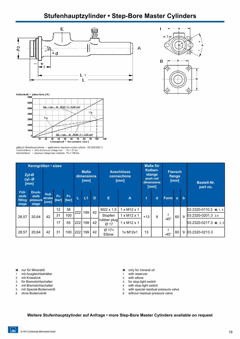
19© 2015 Continental Aftermarket GmbH
Kenngrößen • sizesMaße
dimensions[mm]
Anschlüsseconnections
[mm]
Maße fürKolben- stangepush rod
dimensions[mm]
Flanschflange[mm] Bestell-Nr.
part no.
Zyl-Ø cyl.-Ø[mm]
Füll-stufefillingstage
Druck-stufe
pressurestage
Hubstroke[mm]
PU[bar]
PA[bar] L L1 D E A t d Form a b
28,57 20,64 42
12 38222 199 42
M22 x 1,5 1 x M12 x 1
+13 9 I-45° 60 9
03.2320-0110.3 M, 1, 5
31 100 Stopfen rubber plug
Ø 17
1 x M12 x 1 03.2320-0201.3 2,4
17 55 222 199 42 1 x M12 x 1 03.2320-0217.3 M, 2, 5
28,57 20,64 42 31 100 222 199 42 Ø 17+ Elbow 1x M12x1 13 I
-45° 60 9 03.2320-0213.3
M nur für Mineralöl1 mit Ausgleichbehälter2 mit Kniestück3 für Bremslichtschalter4 mit Bremslichtschalter5 mit Spezial-Bodenventil6 ohne Bodenventil
M only for mineral oil1 with reservoir2 with elbow3 for stop-light switch4 with stop-light switch5 with special residual pressure valve6 without residual pressure valve
Stufenhauptzylinder • Step-Bore Master Cylinders
Weitere Stufenhauptzylinder auf Anfrage • more Step-Bore Master Cylinders available on request
20 © 2015 Continental Aftermarket GmbH
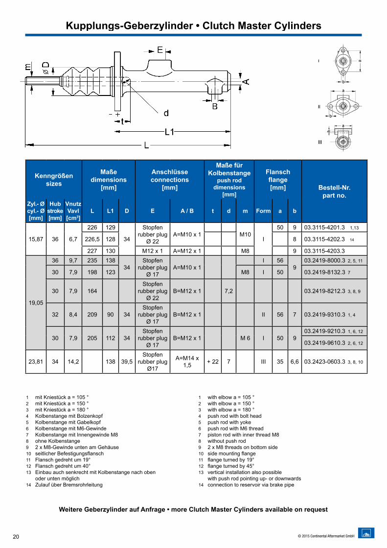
1 mit Kniestück a = 105 °2 mit Kniestück a = 150 °3 mit Kniestück a = 180 °4 Kolbenstange mit Bolzenkopf5 Kolbenstange mit Gabelkopf6 Kolbenstange mit M6-Gewinde7 Kolbenstange mit Innengewinde M88 ohne Kolbenstange9 2 x M8-Gewinde unten am Gehäuse10 seitlicher Befestigungsflansch11 Flansch gedreht um 19°12 Flansch gedreht um 40°13 Einbau auch senkrecht mit Kolbenstange nach oben
oder unten möglich14 Zulauf über Bremsrohrleitung
1 with elbow a = 105 °2 with elbow a = 150 °3 with elbow a = 180 °4 push rod with bolt head5 push rod with yoke6 push rod with M6 thread7 piston rod with inner thread M88 without push rod9 2 x M8 threads on bottom side10 side mounting flange11 flange turned by 19°12 flange turned by 45°13 vertical installation also possible
with push rod pointing up- or downwards14 connection to reservoir via brake pipe
Kenngrößensizes
Maßedimensions
[mm]
Anschlüsseconnections
[mm]
Maße fürKolbenstange
push rod dimensions
[mm]
Flanschflange[mm] Bestell-Nr.
part no.Zyl.- Øcyl.- Ø [mm]
Hubstroke[mm]
VnutzVavl[cm3]
L L1 D E A / B t d m Form a b
15,87 36 6,7
226 129
34
Stopfenrubber plug
Ø 22A=M10 x 1 M10
I
50 9 03.3115-4201.3 1,13
226,5 128 8 03.3115-4202.3 14
227 130 M12 x 1 A=M12 x 1 M8 9 03.3115-4203.3
19,05
36 9,7 235 13834
Stopfenrubber plug
Ø 17A=M10 x 1
I 569
03.2419-8000.3 2, 5, 11
30 7,9 198 123 M8 I 50 03.2419-8132.3 7
30 7,9 164Stopfen
rubber plug Ø 22
B=M12 x 1 7,2 03.2419-8212.3 3, 8, 9
32 8,4 209 90 34Stopfen
rubber plugØ 17
B=M12 x 1 II 56 7 03.2419-9310.3 1, 4
30 7,9 205 112 34Stopfen
rubber plugØ 17
B=M12 x 1 M 6 I 50 903.2419-9210.3 1, 6, 12
03.2419-9610.3 2, 6, 12
23,81 34 14,2 138 39,5Stopfen
rubber plugØ17
A=M14 x 1,5 + 22 7 III 35 6,6 03.2423-0603.3 3, 8, 10
Weitere Geberzylinder auf Anfrage • more Clutch Master Cylinders available on request
Kupplungs-Geberzylinder • Clutch Master Cylinders
21© 2015 Continental Aftermarket GmbH
Kenngrößensizes
Maßedimensions
[mm]
Anschlüsseconnections
[mm]
Maße fürKolbenstange
push rod dimensions
[mm]
Flanschflange[mm] Bestell-Nr.
part no.Zyl.- Øcyl.- Ø [mm]
Hubstroke[mm]
VnutzVavl[cm3]
L L1 D E A / B t d m Form a b
15,87 36 6,7
226 129
34
Stopfenrubber plug
Ø 22A=M10 x 1 M10
I
50 9 03.3115-4201.3 1,13
226,5 128 8 03.3115-4202.3 14
227 130 M12 x 1 A=M12 x 1 M8 9 03.3115-4203.3
19,05
36 9,7 235 13834
Stopfenrubber plug
Ø 17A=M10 x 1
I 569
03.2419-8000.3 2, 5, 11
30 7,9 198 123 M8 I 50 03.2419-8132.3 7
30 7,9 164Stopfen
rubber plug Ø 22
B=M12 x 1 7,2 03.2419-8212.3 3, 8, 9
32 8,4 209 90 34Stopfen
rubber plugØ 17
B=M12 x 1 II 56 7 03.2419-9310.3 1, 4
30 7,9 205 112 34Stopfen
rubber plugØ 17
B=M12 x 1 M 6 I 50 903.2419-9210.3 1, 6, 12
03.2419-9610.3 2, 6, 12
23,81 34 14,2 138 39,5Stopfen
rubber plugØ17
A=M14 x 1,5 + 22 7 III 35 6,6 03.2423-0603.3 3, 8, 10
Zyl.- Øcyl.- Ø [mm]
Hubstroke[mm]
Kolbenfläche piston area
[cm2]
max. Schluckvolumenmax. vol. required
[cm3]
Anschlüsseconnections
A [mm]
Maßedimensions [mm] Bestell-Nr.
part no.L L1 L2 D
19,05 24 2,85 6,84 M10 x 1 77 49 33 28,4 03.2519-1402.3 20,64 23 3,35 7,70 M10 x 1 126 69,7 32,2 28,4 03.2520-1001.3 1
25,411,5
5,075,83 M12 x 1 130 58 31 35 03.2525-1802.3 1, 2
22,5 11,40 M12 x 1 140 52 39,5 37 03.2525-2201.3 1, 3
Zyl.- Øcyl.- Ø [mm]
Hubstroke[mm]
Kolbenfläche piston area
[cm2]
max. Schluckvolumenmax. vol. required
[cm3]
Anschlüsseconnections
A [mm]
Maßedimensions [mm] Bestell-Nr.
part no.L L1 L2 d a
20,64 23 3,35 7,70 M10 x 1 152 111 65,3 9 60 03.2520-1201.3 1, 4, 6
23,81 20 4,45 8,90 M12 x 1151 107
78 960 03.2523-0811.3 1
152 105 57,203.2523-1210.303.2523-1310.3
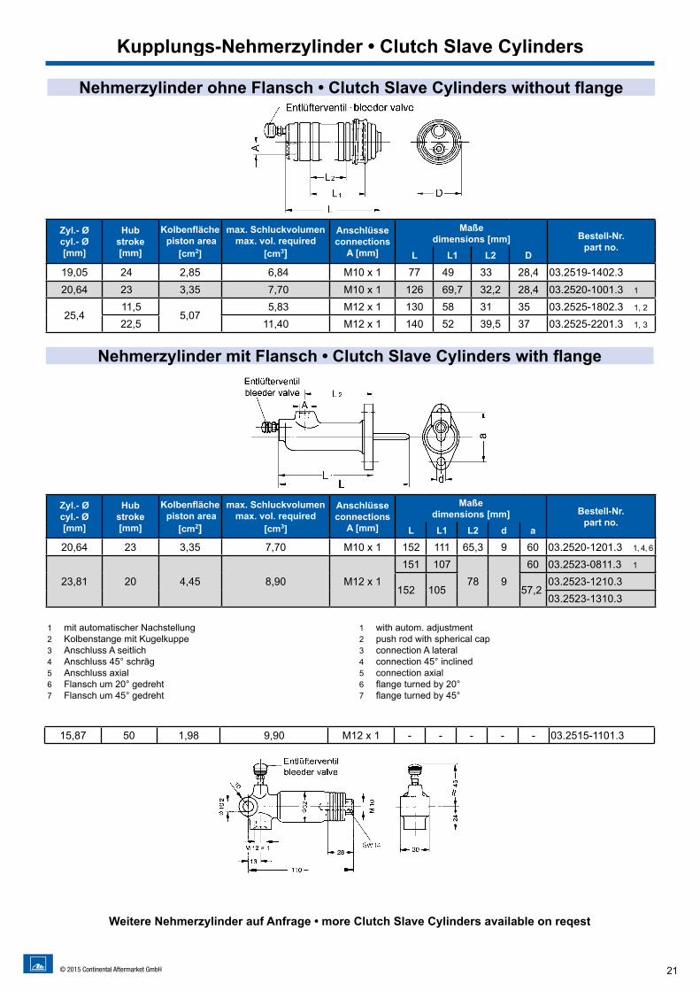
Nehmerzylinder ohne Flansch • Clutch Slave Cylinders without flange
Nehmerzylinder mit Flansch • Clutch Slave Cylinders with flange
15,87 50 1,98 9,90 M12 x 1 - - - - - 03.2515-1101.3
1 mit automatischer Nachstellung2 Kolbenstange mit Kugelkuppe3 Anschluss A seitlich4 Anschluss 45° schräg5 Anschluss axial6 Flansch um 20° gedreht7 Flansch um 45° gedreht
1 with autom. adjustment2 push rod with spherical cap3 connection A lateral4 connection 45° inclined5 connection axial6 flange turned by 20°7 flange turned by 45°
Weitere Nehmerzylinder auf Anfrage • more Clutch Slave Cylinders available on reqest
Kupplungs-Nehmerzylinder • Clutch Slave Cylinders
22 © 2015 Continental Aftermarket GmbH
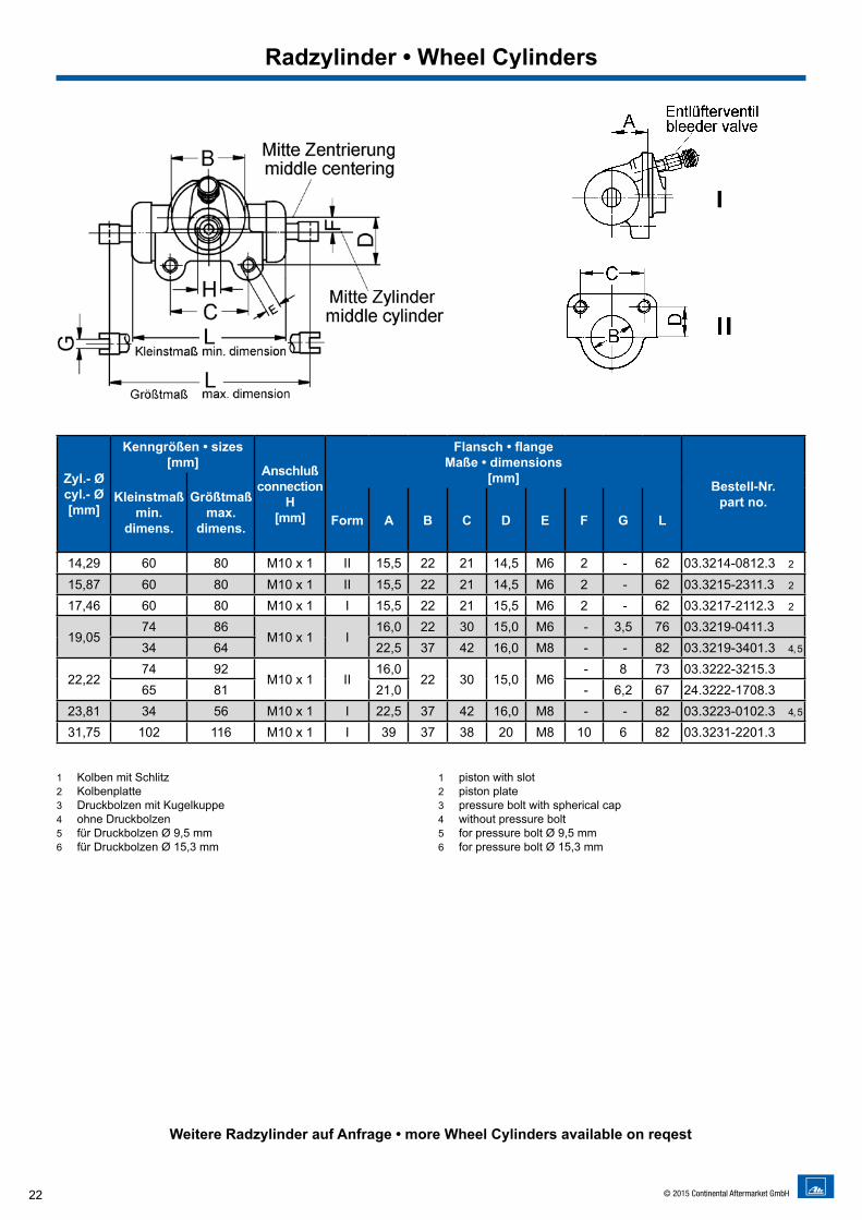
Zyl.- Ø cyl.- Ø [mm]
Kenngrößen • sizes[mm] Anschluß
connectionH
[mm]
Flansch • flange Maße • dimensions
[mm] Bestell-Nr.part no.Kleinstmaß
min. dimens.
Größtmaßmax.
dimens. Form A B C D E F G L
14,29 60 80 M10 x 1 II 15,5 22 21 14,5 M6 2 - 62 03.3214-0812.3 2
15,87 60 80 M10 x 1 II 15,5 22 21 14,5 M6 2 - 62 03.3215-2311.3 2
17,46 60 80 M10 x 1 I 15,5 22 21 15,5 M6 2 - 62 03.3217-2112.3 2
19,0574 86
M10 x 1 I16,0 22 30 15,0 M6 - 3,5 76 03.3219-0411.3
34 64 22,5 37 42 16,0 M8 - - 82 03.3219-3401.3 4, 5
22,2274 92
M10 x 1 II16,0
22 30 15,0 M6 - 8 73 03.3222-3215.3
65 81 21,0 - 6,2 67 24.3222-1708.323,81 34 56 M10 x 1 I 22,5 37 42 16,0 M8 - - 82 03.3223-0102.3 4, 5
31,75 102 116 M10 x 1 I 39 37 38 20 M8 10 6 82 03.3231-2201.3
1 Kolben mit Schlitz2 Kolbenplatte3 Druckbolzen mit Kugelkuppe4 ohne Druckbolzen5 für Druckbolzen Ø 9,5 mm6 für Druckbolzen Ø 15,3 mm
1 piston with slot2 piston plate3 pressure bolt with spherical cap4 without pressure bolt5 for pressure bolt Ø 9,5 mm6 for pressure bolt Ø 15,3 mm
Weitere Radzylinder auf Anfrage • more Wheel Cylinders available on reqest
Radzylinder • Wheel Cylinders
23© 2015 Continental Aftermarket GmbH
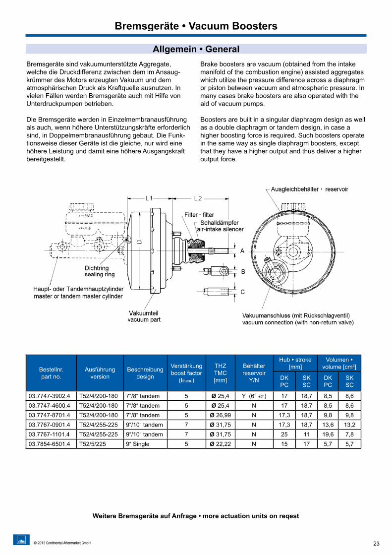
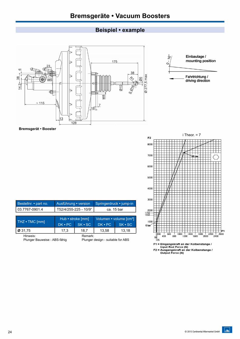
Bremsgeräte sind vakuumunterstützte Aggregate, welche die Druckdifferenz zwischen dem im Ansaug-krümmer des Motors erzeugten Vakuum und dem atmosphärischen Druck als Kraftquelle ausnutzen. In vielen Fällen werden Bremsgeräte auch mit Hilfe von Unterdruckpumpen betrieben.
Die Bremsgeräte werden in Einzelmembranausführung als auch, wenn höhere Unterstützungskräfte erforderlich sind, in Doppelmembranausführung gebaut. Die Funk-tionsweise dieser Geräte ist die gleiche, nur wird eine höhere Leistung und damit eine höhere Ausgangskraft bereitgestellt.
Brake boosters are vacuum (obtained from the intake manifold of the combustion engine) assisted aggregates which utilize the pressure difference across a diaphragm or piston between vacuum and atmospheric pressure. In many cases brake boosters are also operated with the aid of vacuum pumps.
Boosters are built in a singular diaphragm design as well as a double diaphragm or tandem design, in case a higher boosting force is required. Such boosters operate in the same way as single diaphragm boosters, except that they have a higher output and thus deliver a higher output force.
Allgemein • General
Bremsgeräte • Vacuum Boosters
Bestellnr. part no.
Ausführungversion
Beschreibungdesign
Verstärkungboost factor
(Itheor.)
THZTMC [mm]
Behälterreservoir
Y/N
Hub • stroke [mm]
Volumen • volume [cm³]
DK PC
SK SC
DK PC
SK SC
03.7747-3902.4 T52/4/200-180 7“/8“ tandem 5 Ø 25,4 Y (6° ±2°) 17 18,7 8,5 8,603.7747-4600.4 T52/4/200-180 7“/8“ tandem 5 Ø 25,4 N 17 18,7 8,5 8,603.7747-8701.4 T52/4/200-180 7“/8“ tandem 5 Ø 26,99 N 17,3 18,7 9,8 9,803.7767-0901.4 T52/4/255-225 9“/10“ tandem 7 Ø 31,75 N 17,3 18,7 13,6 13,203.7767-1101.4 T52/4/255-225 9“/10“ tandem 7 Ø 31,75 N 25 11 19,6 7,803.7854-6501.4 T52/5/225 9“ Single 5 Ø 22,22 N 15 17 5,7 5,7
Weitere Bremsgeräte auf Anfrage • more actuation units on reqest
24 © 2015 Continental Aftermarket GmbH
Bestellnr. • part no. Ausführung • version Springerdruck • jump-in03.7767-0901.4 T52/4/255-225 - 10/9“ ca. 15 bar
THZ • TMC [mm]Hub • stroke [mm] Volumen • volume [cm³]
DK • PC SK • SC DK • PC SK • SCØ 31,75 17,3 18,7 13,58 13,18
Bremsgerät • Boosteri Theor. = 7
Bremsgeräte • Vacuum Boosters
Hinweis: Plunger Bauweise - ABS-fähig
Remark: Plunger design - suitable for ABS
Beispiel • example
25© 2015 Continental Aftermarket GmbH
Hydraulischer Verstärker • Hydraulic Booster
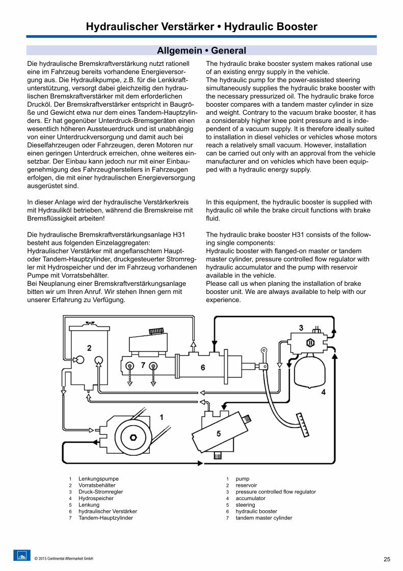
Allgemein • GeneralDie hydraulische Bremskraftverstärkung nutzt rationell eine im Fahrzeug bereits vorhandene Energieversor-gung aus. Die Hydraulikpumpe, z.B. für die Lenkkraft-unterstützung, versorgt dabei gleichzeitig den hydrau-lischen Bremskraftverstärker mit dem erforderlichen Drucköl. Der Bremskraftverstärker entspricht in Baugrö-ße und Gewicht etwa nur dem eines Tandem-Hauptzylin-ders. Er hat gegenüber Unterdruck-Bremsgeräten einen wesentlich höheren Aussteuerdruck und ist unabhängig von einer Unterdruckversorgung und damit auch bei Dieselfahrzeugen oder Fahrzeugen, deren Motoren nur einen geringen Unterdruck erreichen, ohne weiteres ein-setzbar. Der Einbau kann jedoch nur mit einer Einbau-genehmigung des Fahrzeugherstellers in Fahrzeugen erfolgen, die mit einer hydraulischen Energieversorgung ausgerüstet sind.
In dieser Anlage wird der hydraulische Verstärkerkreis mit Hydrauliköl betrieben, während die Bremskreise mit Bremsflüssigkeit arbeiten!
Die hydraulische Bremskraftverstärkungsanlage H31 besteht aus folgenden Einzelaggregaten:Hydraulischer Verstärker mit angeflanschtem Haupt- oder Tandem-Hauptzylinder, druckgesteuerter Stromreg-ler mit Hydrospeicher und der im Fahrzeug vorhandenen Pumpe mit Vorratsbehälter.Bei Neuplanung einer Bremskraftverstärkungsanlage bitten wir um Ihren Anruf. Wir stehen Ihnen gern mit unserer Erfahrung zu Verfügung.
The hydraulic brake booster system makes rational use of an existing enrgy supply in the vehicle.The hydraulic pump for the power-assisted steering simultaneously supplies the hydraulic brake booster with the necessary pressurized oil. The hydraulic brake force booster compares with a tandem master cylinder in size and weight. Contrary to the vacuum brake booster, it has a considerably higher knee point pressure and is inde-pendent of a vacuum supply. It is therefore ideally suited to installation in diesel vehicles or vehicles whose motors reach a relatively small vacuum. However, installation can be carried out only with an approval from the vehicle manufacturer and on vehicles which have been equip-ped with a hydraulic energy supply.
In this equipment, the hydraulic booster is supplied with hydraulic oil while the brake circuit functions with brake fluid.
The hydraulic brake booster H31 consists of the follow-ing single components:Hydraulic booster with flanged-on master or tandem master cylinder, pressure controlled flow regulator with hydraulic accumulator and the pump with reservoir available in the vehicle.Please call us when planing the installation of brake booster unit. We are always available to help with our experience.
1 Lenkungspumpe2 Vorratsbehälter3 Druck-Stromregler4 Hydrospeicher5 Lenkung6 hydraulischer Verstärker7 Tandem-Hauptzylinder
1 pump2 reservoir3 pressure controlled flow regulator4 accumulator5 steering6 hydraulic booster7 tandem master cylinder
26 © 2015 Continental Aftermarket GmbH
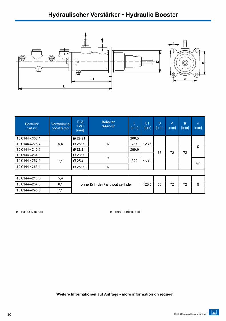
Hydraulischer Verstärker • Hydraulic Booster
Weitere Informationen auf Anfrage • more information on request
M nur für Mineralöl M only for mineral oil
Bestellnr. part no.
Verstärkungboost factor
THZTMC [mm]
Behälterreservoir
L [mm]
L1 [mm]
D [mm]
A [mm]
B [mm]
d [mm]
10.0144-4300.45,4
Ø 23,81N
206,5123,5
68 72 72
910.0144-4278.4 Ø 26,99 28710.0144-4216.3 Ø 22,2 289,910.0144-4234.3
7,1
Ø 26,99Y
158,510.0144-4257.4 Ø 25,4 322M8
10.0144-4263.4 Ø 26,99 N
10.0144-4210.3 5,4
ohne Zylinder / without cylinder 123,5 68 72 72 910.0144-4234.3 6,1
10.0144-4245.3 7,1
27© 2015 Continental Aftermarket GmbH
ABS/ESC Systeme • ABS/ESC Systems
Leistungen • What you getModerne Hochleistungs-ABS/ESC Systeme MK70,MK25 und MK100 mit folgenden Funktionen: • Anti-lock Braking System (ABS) • Active Yaw Control (AYC) • Electronic Brake force Distribution (EBD) • Hydraulic Brake Assist (HBA) • Traction Control System (TCS)Weitere Funktionen auf Anfrage.
Advanced high performance ABS/ESC systems MK70,MK25 and MK100 with with following functions: • Anti-lock Braking System (ABS) • Active Yaw Control (AYC) • Electronic Brake force Distribution (EBD) • Hydraulic Brake Assist (HBA) • Traction Control System (TCS)More functions available on request
Fahrzeug- und SystemvoraussetzungenVehicle- and system preconditions
• S/W oder X Aufteilung • Heckantrieb oder Frontantriebsversion• Aktive Raddrehzahlsensoren• Lenkwinkelsensor (für ESC)• CAN Schnittstelle (für ESC)
• F/R or X split• RWD or FWD• Active wheel speed sensors• Steering Angle Sensor (for ESC)• CAN Interface (for ESC)
Projektablauf • Project procedure• Fahrzeugauslegung• Prototypaufbau• Raddrehzahlsensoreinbau sowie Kabelverlegung (falls erforderlich)• Einbau des Systems und der Sensorik• Einbau der Messtechnik• Fahrversuche auf Untergründen mit hohen und niedrigen Reibwerten• Anpassung der Regelparameter• Freigabe des Systems und Vorbereitung für den Serienanlauf• Unterstützung zur Homologation auf Anfrage• Bereitstellung von Diagnosesoftware für End-of-Line-Test und Werkstatt
• Vehicle configuration • Prototype construction• Wheel speed sensor installation and wiring (if necessary)• Installation of ABS system including sensors • Installation of measurement instruments • Driving tests on surfaces with high and low friction coefficients• Tuning of control parameters• System release and preparation for product start • Homologation support upon request • Provision of diagnosis software for end-of-line test and service stations
Individuelle ABS/ESC Systeme für Klein- und Spezialserien Individual ABS/ESC Systems for Small and Special Series
Ihren Spezifikationen entsprechend stellen wir für Sie ein individuelles ABS/ESC System zusammen.
According to your specifications we design an individual ABS/ESC system for you.
ABS/ESC-Großserien-Technologie...
jetzt auch für Kleinserien verfügbar!
ABS/ESC Large SeriesTechnology...
now also available for Small Series!
28 © 2015 Continental Aftermarket GmbH
Fahrzeug- und SystemvoraussetzungenVehicle- and system preconditions
Leistungen • What you getZu unserem ABS/ESC System können wir Ihnen auch den benötigten Raddrehzahlsensor anbieten. Dieser aus der Großserie abgeleitete aktive Sensor überzeugt durch seine Zuverlässigkeit und Robustheit. Aufgrund seiner großen Luftspalttoleranz kann er mit wenig Aufwand im Fahrzeug adaptiert werden.
We can also supply you the necessary wheel speed sensor for your ABS/ESC system. This active sensor, derived from the large series production, features high reliability and robustness. Due to its large air gap tolerance it can be fitted to the vehicle with little effort.
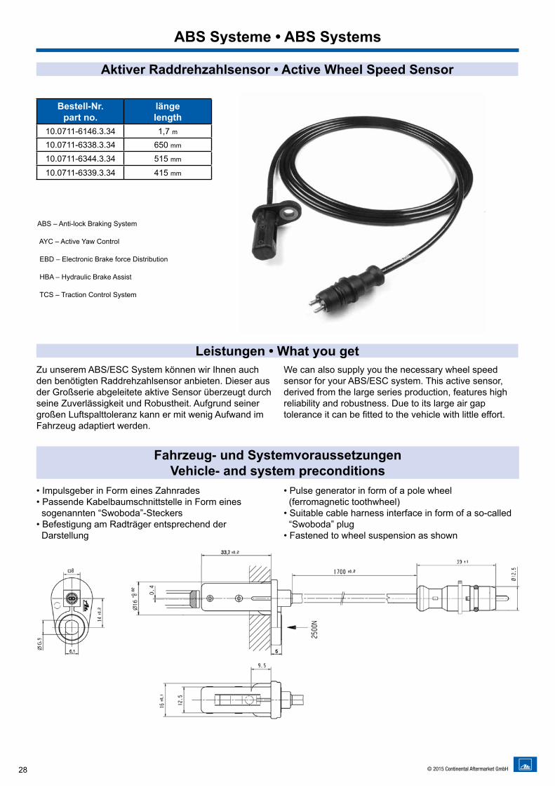
• Impulsgeber in Form eines Zahnrades• Passende Kabelbaumschnittstelle in Form eines sogenannten “Swoboda”-Steckers• Befestigung am Radträger entsprechend der Darstellung
• Pulse generator in form of a pole wheel (ferromagnetic toothwheel)• Suitable cable harness interface in form of a so-called “Swoboda” plug• Fastened to wheel suspension as shown
ABS Systeme • ABS Systems
Aktiver Raddrehzahlsensor • Active Wheel Speed Sensor
Bestell-Nr.part no.
länge length
10.0711-6146.3.34 1,7 m10.0711-6338.3.34 650 mm
10.0711-6344.3.34 515 mm
10.0711-6339.3.34 415 mm
ABS – Anti-lock Braking System
AYC – Active Yaw Control
EBD – Electronic Brake force Distribution
HBA – Hydraulic Brake Assist
TCS – Traction Control System
29© 2015 Continental Aftermarket GmbH
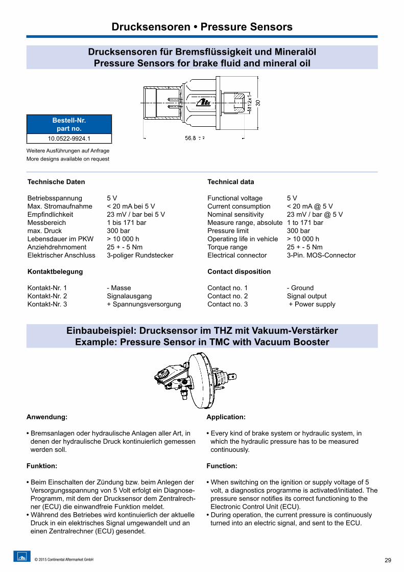
Drucksensoren für Bremsflüssigkeit und MineralölPressure Sensors for brake fluid and mineral oil
Einbaubeispiel: Drucksensor im THZ mit Vakuum-VerstärkerExample: Pressure Sensor in TMC with Vacuum Booster
Anwendung:
• Bremsanlagen oder hydraulische Anlagen aller Art, in denen der hydraulische Druck kontinuierlich gemessen werden soll.
Funktion:
• Beim Einschalten der Zündung bzw. beim Anlegen der Versorgungsspannung von 5 Volt erfolgt ein Diagnose-Programm, mit dem der Drucksensor dem Zentralrech-ner (ECU) die einwandfreie Funktion meldet.
• Während des Betriebes wird kontinuierlich der aktuelle Druck in ein elektrisches Signal umgewandelt und an einen Zentralrechner (ECU) gesendet.
Application:
• Every kind of brake system or hydraulic system, in which the hydraulic pressure has to be measured continuously.
Function:
• When switching on the ignition or supply voltage of 5 volt, a diagnostics programme is activated/initiated. The pressure sensor notifies its correct functioning to the Electronic Control Unit (ECU).
• During operation, the current pressure is continuously turned into an electric signal, and sent to the ECU.
Drucksensoren • Pressure Sensors
Bestell-Nr.part no.
10.0522-9924.1
Weitere Ausführungen auf AnfrageMore designs available on request
Technische Daten
Betriebsspannung 5 VMax. Stromaufnahme < 20 mA bei 5 VEmpfindlichkeit 23 mV / bar bei 5 VMessbereich 1 bis 171 bar max. Druck 300 barLebensdauer im PKW > 10 000 h Anziehdrehmoment 25 + - 5 NmElektrischer Anschluss 3-poliger Rundstecker
Kontaktbelegung
Kontakt-Nr. 1 - MasseKontakt-Nr. 2 SignalausgangKontakt-Nr. 3 + Spannungsversorgung
Technical data Functional voltage 5 VCurrent consumption < 20 mA @ 5 VNominal sensitivity 23 mV / bar @ 5 VMeasure range, absolute 1 to 171 barPressure limit 300 barOperating life in vehicle > 10 000 hTorque range 25 + - 5 NmElectrical connector 3-Pin. MOS-Connector Contact disposition
Contact no. 1 - GroundContact no. 2 Signal outputContact no. 3 + Power supply
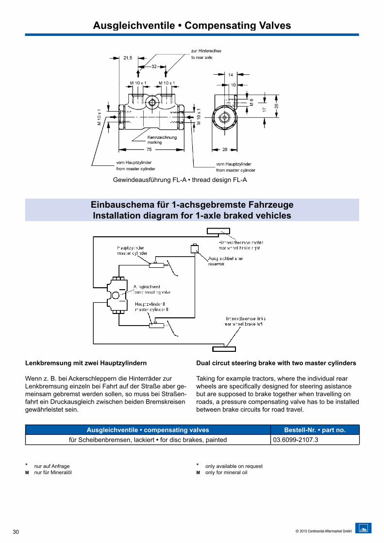
30 © 2015 Continental Aftermarket GmbH
Einbauschema für 1-achsgebremste FahrzeugeInstallation diagram for 1-axle braked vehicles
Lenkbremsung mit zwei Hauptzylindern
Wenn z. B. bei Ackerschleppern die Hinterräder zur Lenkbremsung einzeln bei Fahrt auf der Straße aber ge-meinsam gebremst werden sollen, so muss bei Straßen-fahrt ein Druckausgleich zwischen beiden Bremskreisen gewährleistet sein.
Dual circut steering brake with two master cylinders
Taking for example tractors, where the individual rear wheels are specifically designed for steering asistance but are supposed to brake together when travelling on roads, a pressure compensating valve has to be installed between brake circuits for road travel.
Ausgleichventile • compensating valves Bestell-Nr. • part no.für Scheibenbremsen, lackiert • for disc brakes, painted 03.6099-2107.3
* nur auf Anfrage M nur für Mineralöl
* only available on request M only for mineral oil
Ausgleichventile • Compensating Valves
Gewindeausführung FL-A • thread design FL-A
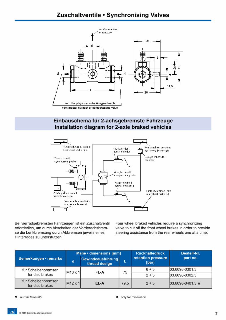
31© 2015 Continental Aftermarket GmbH
Bemerkungen • remarksMaße • dimensions [mm] Rückhaltedruck
retention pressure [bar]
Bestell-Nr.part no.
d Gewindeausführung thread design L
für Scheibenbremsenfor disc brakes M10 x 1 FL-A 75
6 + 3 03.6098-0301.32 + 3 03.6098-0302.3
für Scheibenbremsen for disc brakes M12 x 1 EL-A 79,5 2 + 3 03.6098-0401.3 M
M nur für Mineralöl M only for mineral oil
Bei vierradgebremsten Fahrzeugen ist ein Zuschaltventil erforderlich, um durch Abschalten der Vorderachsbrem-se die Lenkbremsung durch Abbremsen jeweils eines Hinterrades zu unterstützen.
Four wheel braked vehicles require a synchronizing valve to cut off the front wheel brakes in order to provide steering assistance from the rear wheels one at a time.
Einbauschema für 2-achsgebremste FahrzeugeInstallation diagram for 2-axle braked vehicles
Zuschaltventile • Synchronising Valves
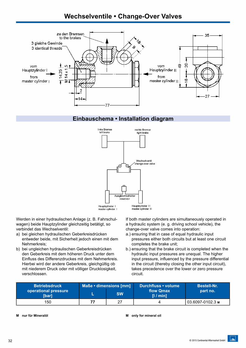
32 © 2015 Continental Aftermarket GmbH
Betriebsdruckoperational pressure
[bar]
Maße • dimensions [mm] Durchfluss • volume flow Qmax
[l / min]
Bestell-Nr.part no.
L SW
150 77 27 4 03.6097-0102.3 M
Werden in einer hydraulischen Anlage (z. B. Fahrschul-wagen) beide Hauptzylinder gleichzeitig betätigt, soverbindet das Wechselventil:a) bei gleichen hydraulischen Geberkreisdrücken
entweder beide, mit Sicherheit jedoch einen mit dem Nehmerkreis;
b) bei ungleichen hydraulischen Geberkreisdrücken den Geberkreis mit dem höheren Druck unter dem Einfluss des Differenzdruckes mit dem Nehmerkreis. Hierbei wird der andere Geberkreis, gleichgültig ob mit niederem Druck oder mit völliger Drucklosigkeit, verschlossen.
If both master cylinders are simultaneously operated in a hydraulic system (e. g. driving school vehicle), thechange-over valve comes into operation:a.) ensuring that in case of equal hydraulic input
pressures either both circuits but at least one circuit completes the brake unit;
b.) ensuring that the brake circuit is completed when the hydraulic input pressures are unequal. The higher input pressure, influenced by the pressure differential in the circuit (thereby closing the other input circuit), takes precedence over the lower or zero pressure circuit.
Einbauschema • Installation diagram
Wechselventile • Change-Over Valves
M nur für Mineralöl M only for mineral oil
33© 2015 Continental Aftermarket GmbH
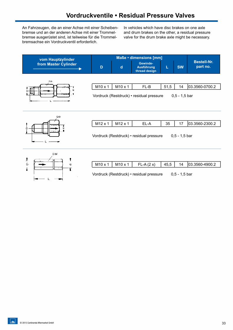
An Fahrzeugen, die an einer Achse mit einer Scheiben-bremse und an der anderen Achse mit einer Trommel-bremse ausgerüstet sind, ist teilweise für die Trommel-bremsachse ein Vordruckventil erforderlich.
In vehicles which have disc brakes on one axleand drum brakes on the other, a residual pressure valve for the drum brake axle might be necessary.
Vordruckventile • Residual Pressure Valves
M10 x 1 M10 x 1 FL-B 51,5 14 03.3560-0700.2
Vordruck (Restdruck) • residual pressure 0,5 - 1,5 bar
M12 x 1 M12 x 1 EL-A 35 17 03.3560-2300.2
Vordruck (Restdruck) • residual pressure 0,5 - 1,5 bar
M10 x 1 M10 x 1 FL-A (2 x) 45,5 14 03.3560-4900.2
Vordruck (Restdruck) • residual pressure 0,5 - 1,5 bar
vom Hauptzylinder from Master Cylinder
►
Maße • dimensions [mm]Bestell-Nr.
part no.D dGewinde-
Ausführungthread design
L SW
34 © 2015 Continental Aftermarket GmbH
ATE Bremsflüssigkeiten (ausser LHM PLUS) dürfen nicht in Bremsanlagen eingefüllt werden, die für den Betrieb mit Mineral-Hydrauliköl ausgelegt sind.ATE Brake Fluids (except LHM PLUS) must not be poured into brake systems that are designed for use with mineral hydraulic oil.
DOT = US-amerikanisches Sicherheitsgesetz für BremsflüssigkeitDOT = US Department of Transportation legal safety standards for brake fluids
Zur Erhaltung der Funktionssicherheit der Bremsanlage muss Bremsflüssigkeit entsprechend der vom Fahrzeughersteller vorgegebenen Qualität und den Wechselintervallen gewechselt werden.To maintain the functional reliability of the brake system, brake fluid must be changed according to the specifications of the vehicle manufacturer (quality and change interval).
für Fahrzeugbaujahre bis ca. 1990for vehicles built up to 1990
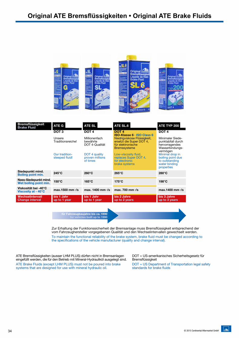
Bremsflüssigkeit ATE G ATE SL ATE SL.6 ATE TYP 200Brake Fluid DOT 3 DOT 4 DOT 4 DOT 4 ISO-Klasse 6 · ISO Class 6 Unsere Millionenfach Niedrigviskose Flüssigkeit, Minimaler Siede- Traditionsreiche! bewährte ersetzt die Super DOT 4, punkt abfall durch DOT 4-Qualität für elektronische hervorragendes Bremssysteme Wasserbindungs- vermögen Our tradition- DOT 4 quality Low-viscosity fluid, Minimal drop in steeped fluid! proven millions replaces Super DOT 4, boiling point due of times for electronic to outstanding brake systems water binding propertiesSiedepunkt mind.Boiling point min. 245°C 260°C 265°C 280°C
Nass-Siedepunkt mind.Wet boiling point min. 150°C 165°C 175°C 198°C
Viskosität bei -40°C Viscosity at - 40°C max.1500 mm 2/s max. 1400 mm 2/s max. 700 mm 2/s max.1400 mm 2/s
Wechselintervall bis 1 Jahr bis 1 Jahr bis 2 Jahre bis 3 Jahre Change interval up to 1 year up to 1 year up to 2 years up to 3 years
The new racing quality
Original ATE Bremsflüssigkeiten • Original ATE Brake Fluids
35© 2015 Continental Aftermarket GmbH
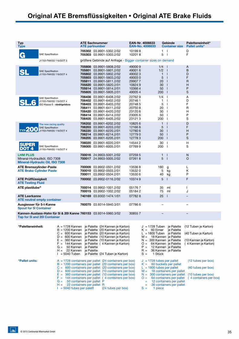
*Paletteneinheit: A = 1728 Kannen je Palette (24 Kannen je Karton) J = 1728 Tuben je Palette (12 Tuben je Karton) B = 1200 Kannen je Palette (20 Kannen je Karton) K = 60 Eimer je Palette C = 600 Kannen je Palette (20 Kannen je Karton) L = 1800 Tuben je Palette (40 Tuben je Karton) D = 600 Kannen je Palette (10 Kannen je Karton) M = 18 Kannen je Palette E = 360 Kannen je Palette (10 Kannen je Karton) N = 300 Kannen je Palette (10 Kannen je Karton) F = 144 Kannen je Palette ( 4 Kannen je Karton) O = 64 Kannen je Palette ( 4 Kannen je Karton) G = 50 Kannen je Palette P = 12 Kannen je Palette H = 22 Kannen je Palette R = 36 Kannen je Palette I = 5040 Tuben je Palette (24 Tuben je Karton) S = 1 Stück
*Pallet units: A = 1728 containers per pallet (24 containers per box) J = 1728 tubes per pallet (12 tubes per box) B = 1200 containers per pallet (20 containers per box) K = 60 buckets per pallet C = 600 containers per pallet (20 containers per box) L = 1800 tubes per pallet (40 tubes per box) D = 600 containers per pallet (10 containers per box) M = 18 containers per pallet E = 360 containers per pallet (10 containers per box) N = 300 containers per pallet (10 tubes per box) F = 144 containers per pallet ( 4 containers per box) O = 64 containers per pallet ( 4 containers per box) G = 50 containers per pallet P = 12 containers per pallet H = 22 containers per pallet R = 36 containers per pallet I = 5040 tubes per palett (24 tubes per box) S = 1 piece
Typ ATE Sachnummer EAN-Nr. 4006633 Gebinde Paletteneinheit*Type ATE partnumber EAN-No. 4006633 Container size Pallet units* 705302 03.9901-5302.2/02 10199 8 1 l D 705303 03.9901-5303.2/02 10201 8 5 l F
705808 03.9901-5808.2/02 49000 9 1/4 l A 705801 03.9901-5801.2/02 49001 6 1/2 l B 705802 03.9901-5802.2/02 49002 3 1 l D 705803 03.9901-5803.2/02 49003 0 5 l F 705811 03.9901-5811.2/02 29907 7 20 l R 705820 03.9901-5820.2/01 10824 9 30 l H 705814 03.9901-5814.2/01 10366 4 50 l P 705805 03.9901-5805.2/01 49005 4 200 l S
706408 03.9901-6408.2/02 22762 9 1/4 l A 706402 03.9901-6402.2/02 20746 1 1 l D 706403 03.9901-6403.2/02 20748 5 5 l F 706411 03.9901-6411.2/02 20750 8 20 l R 706420 03.9901-6420.2/02 23120 6 30 l H 706414 03.9901-6414.2/02 23005 6 50 l P 706405 03.9901-6405.2/02 23121 3 200 I S
706202 03.9901-6202.2/02 10825 6 1 l D 706203 03.9901-6203.2/02 12166 8 5 l F 706220 03.9901-6220.2/01 12780 6 30 l H 706214 03.9901-6214.2/01 12779 0 50 l P 706205 03.9901-6205.2/01 12778 3 200 l S
706020 03.9901-6020.2/01 14544 2 30 I H 706005 03.9901-6005.2/01 07769 9 200 I S
LHM PLUS 700016 24.9903-5001.2/02 07259 5 1 l NMineral-Hydrauliköl, ISO 7308 700017 24.9903-5005.2/02 07261 8 5 l OMineral-Hydraulic Oil, ISO 7308ATE Bremszylinder-Paste 700009 03.9902-0501.2/02 13536 8 180 g L ATE Brake Cylinder Paste 700010 03.9902-0503.2/01 13532 0 5 kg K 700011 03.9902-0504.2/01 13530 6 40 kg P ATE Prüfflüssigkeit 700002 03.9902-0116.2/02 10374 9 5 l FATE Testing Fluid
ATE plastilube® 700014 03.9902-1001.2/02 05176 7 35 ml I 700015 03.9902-1002.2/02 05184 2 75 ml J
ATE Leerkanne 740169 03.9302-1474.1/01 07782 8 25 l – ATE neutral empty container Ausgiesser für 5-l-Kanne 760070 03.9314-5940.3/01 07786 6 – – Spout for 5l Container
Kannen-Auslass-Hahn für 5l & 20l Kanne 760153 03.9314-5960.3/02 30855 7 – – Tap for 5l and 20l Container
SAE Spezifikation
J1703-FMVSS 116/DOT 3
SAE Spezifikation J1703-FMVSS 116/DOT 4
SAE Spezifikation J1703-FMVSS 116/DOT 4
SAE Spezifikation J1703-FMVSS 116/DOT 4 ISO Klasse 6 - niedrigviskos
SAE Spezifikation J1703-FMVSS 116/DOT 4
größere Gebinde auf Anfrage - Bigger container sizes on demand
The new racing quality
Original ATE Bremsflüssigkeiten • Original ATE Brake Fluids
36 © 2015 Continental Aftermarket GmbH
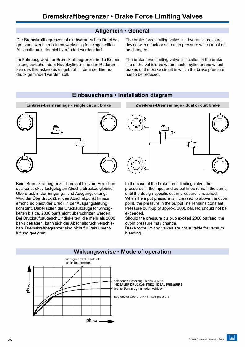
Der Bremskraftbegrenzer ist ein hydraulisches Druckbe-grenzungsventil mit einem werkseitig festeingestellten Abschaltdruck, der nicht verändert werden darf.
Im Fahrzeug wird der Bremskraftbegrenzer in die Brems-leitung zwischen dem Hauptzylinder und den Radbrem-sen des Bremskreises eingebaut, in dem der Brems-druck gemindert werden soll.
The brake force limiting valve is a hydraulic pressure device with a factory-set cut-in pressure which must not be changed.
The brake force limiting valve is installed in the brake line of the vehicle between master cylinder and wheel brakes of the brake circuit in which the brake pressure has to be reduced.
Beim Bremskraftbegrenzer herrscht bis zum Erreichen des konstruktiv festgelegten Abschaltdruckes gleicher Überdruck in der Eingangs- und Ausgangsleitung. Wird der Überdruck über den Abschaltpunkt hinaus erhöht, so bleibt der Druck in der Ausgangsleitung konstant. Dabei sollen die Druckaufbaugeschwindig-keiten bis ca. 2000 bar/s nicht überschritten werden. Bei Druckaufbaugeschwindigkeiten, die mehr als 2000 bar/s betragen, kann sich der Abschaltdruck verschie-ben. Bremskraftbegrenzer sind nicht für Vakuument- lüftung geeignet.
In the case of the brake force limiting valve, the pressures in the input and output lines remain the same until the design-specific cut-in pressure is reached. When the input pressure is increased to above the cut-in point, the pressure in the output line remains constant. Pressure built-up of approx. 2000 bar/sec should not be exceeded.Should the pressure built-up exceed 2000 bar/sec, the cut-in pressure may change. Brake force limiting valves are not suitable for vacuum bleeding.
Einbauschema • Installation diagram
Wirkungsweise • Mode of operation
Allgemein • General
Einkreis-Bremsanlage • single circuit brake
Bremskraftbegrenzer • Brake Force Limiting Valves
Zweikreis-Bremsanlage • dual circuit brake
37© 2015 Continental Aftermarket GmbH
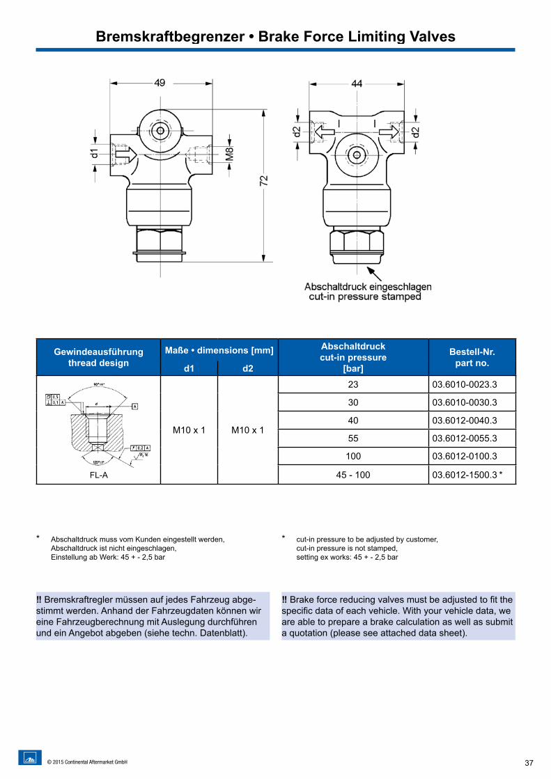
* Abschaltdruck muss vom Kunden eingestellt werden, Abschaltdruck ist nicht eingeschlagen, Einstellung ab Werk: 45 + - 2,5 bar
* cut-in pressure to be adjusted by customer, cut-in pressure is not stamped, setting ex works: 45 + - 2,5 bar
Bremskraftbegrenzer • Brake Force Limiting Valves
‼ Bremskraftregler müssen auf jedes Fahrzeug abge-stimmt werden. Anhand der Fahrzeugdaten können wir eine Fahrzeugberechnung mit Auslegung durchführen und ein Angebot abgeben (siehe techn. Datenblatt).
‼ Brake force reducing valves must be adjusted to fit the specific data of each vehicle. With your vehicle data, we are able to prepare a brake calculation as well as submit a quotation (please see attached data sheet).
Gewindeausführungthread design
Maße • dimensions [mm] Abschaltdruckcut-in pressure
[bar]
Bestell-Nr.part no.d1 d2
FL-A
M10 x 1 M10 x 1
23 03.6010-0023.3
30 03.6010-0030.3
40 03.6012-0040.3
55 03.6012-0055.3
100 03.6012-0100.3
45 - 100 03.6012-1500.3 *
38 © 2015 Continental Aftermarket GmbH
Funktionsbeschreibung • Description of function
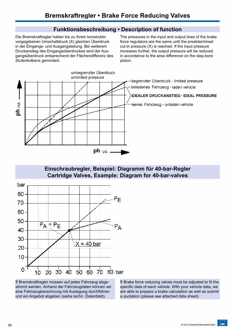
Einschraubregler, Beispiel: Diagramm für 40-bar-ReglerCartridge Valves, Example: Diagram for 40-bar-valves
Die Bremskraftregler haben bis zu ihrem konstruktiv vorgegebenen Umschaltdruck (X) gleichen Überdruck in der Eingangs- und Ausgangsleitung. Bei weiterem Druckanstieg des Eingangsüberdruckes wird der Aus-gangsüberdruck entsprechend der Flächendifferenz des Stufenkolbens gemindert.
The pressures in the input and output lines of the brake force regulators are the same until the predetermined cut-in pressure (X) is reached. If the input pressure increases further, the output pressure will be reduced in accordance to the area difference on the step-bore piston.
Bremskraftregler • Brake Force Reducing Valves
‼ Bremskraftregler müssen auf jedes Fahrzeug abge-stimmt werden. Anhand der Fahrzeugdaten können wir eine Fahrzeugberechnung mit Auslegung durchführen und ein Angebot abgeben (siehe techn. Datenblatt).
‼ Brake force reducing valves must be adjusted to fit the specific data of each vehicle. With your vehicle data, we are able to prepare a brake calculation as well as submit a quotation (please see attached data sheet).
39© 2015 Continental Aftermarket GmbH
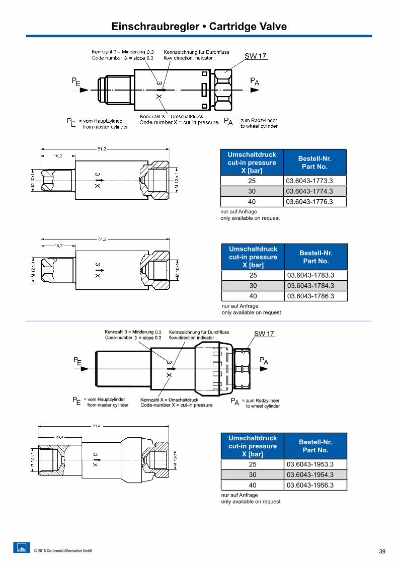
Umschaltdruckcut-in pressure
X [bar]
Bestell-Nr.Part No.
25 03.6043-1773.330 03.6043-1774.340 03.6043-1776.3
nur auf Anfrageonly available on request
Umschaltdruckcut-in pressure
X [bar]
Bestell-Nr.Part No.
25 03.6043-1783.330 03.6043-1784.340 03.6043-1786.3
nur auf Anfrageonly available on request
Umschaltdruckcut-in pressure
X [bar]
Bestell-Nr.Part No.
25 03.6043-1953.330 03.6043-1954.340 03.6043-1956.3
nur auf Anfrageonly available on request
Einschraubregler • Cartridge Valve
40 © 2015 Continental Aftermarket GmbH
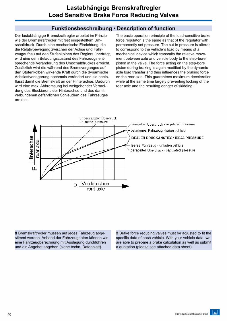
Funktionsbeschreibung • Description of functionDer lastabhängige Bremskraftregler arbeitet im Prinzip wie der Bremskraftregler mit fest eingestelltem Um-schaltdruck. Durch eine mechanische Einrichtung, die die Relativbewegung zwischen der Achse und Fahr-zeugaufbau auf den Stufenkolben des Reglers überträgt, wird eine dem Beladungszustand des Fahrzeugs ent-sprechende Veränderung des Umschaltdruckes erreicht.Zusätzlich wird die während des Bremsvorganges auf den Stufenkolben wirkende Kraft durch die dynamische Achslastverlagerung nochmals verändert und sie beein-flusst damit die Bremskraft an der Hinterachse. Dadurch wird eine max. Abbremsung bei weitgehender Vermei-dung des Blockierens der Hinterachse und des damit verbundenen gefährlichen Schleudern des Fahrzeuges erreicht.
The basic operation principle of the load-sensitive brake force regulator is the same as that of the regulator with permanently set pressure. The cut-in pressure is altered to correspond to the vehicle´s load by means of a mechanical device which transmits the relative move-ment between axle and vehicle body to the step-bore piston in the valve. The force acting on the step-bore piston during braking is again modified by the dynamic axle load transfer and thus influences the braking force on the rear axle. This guarantees maximum deceleration while at the same time largely preventing locking of the rear axle and the resulting danger of skidding.
Lastabhängige BremskraftreglerLoad Sensitive Brake Force Reducing Valves
‼ Bremskraftregler müssen auf jedes Fahrzeug abge-stimmt werden. Anhand der Fahrzeugdaten können wir eine Fahrzeugberechnung mit Auslegung durchführen und ein Angebot abgeben (siehe techn. Datenblatt).
‼ Brake force reducing valves must be adjusted to fit the specific data of each vehicle. With your vehicle data, we are able to prepare a brake calculation as well as submit a quotation (please see attached data sheet).
41© 2015 Continental Aftermarket GmbH
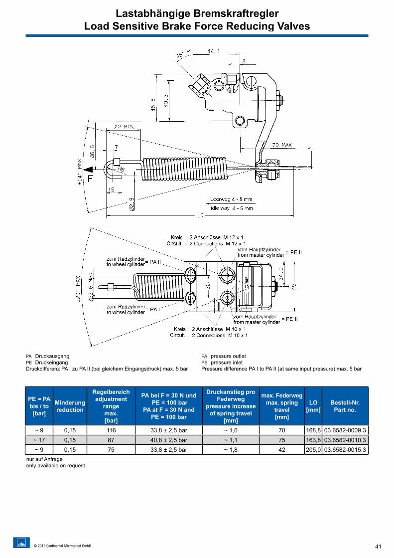
PA DruckausgangPE DruckeingangDruckdifferenz PA I zu PA II (bei gleichem Eingangsdruck) max. 5 bar
PA pressure outletPE pressure inletPressure difference PA I to PA II (at same input pressure) max. 5 bar
PE = PAbis / to [bar]
Minderungreduction
Regelbereichadjustment
rangemax. [bar]
PA bei F = 30 N und PE = 100 bar
PA at F = 30 N and PE = 100 bar
Druckanstieg pro Federweg
pressure increase of spring travel
[mm]
max. Federwegmax. spring
travel [mm]
LO[mm]
Bestell-Nr.Part no.
~ 9 0,15 116 33,8 ± 2,5 bar ~ 1,6 70 168,8 03.6582-0009.3~ 17 0,15 87 40,8 ± 2,5 bar ~ 1,1 75 163,8 03.6582-0010.3~ 9 0,15 75 33,8 ± 2,5 bar ~ 1,8 42 205,0 03.6582-0015.3
nur auf Anfrageonly available on request
Lastabhängige BremskraftreglerLoad Sensitive Brake Force Reducing Valves
D
42 © 2015 Continental Aftermarket GmbH
Ausgleichbehälter • Reservoirs
CBA
1-Kammer-Behälter • Single Chamber Reservoirs
43© 2015 Continental Aftermarket GmbH
Ausgleichbehälter • Reservoirs
1 mit Warneinrichtung, Flachstecker 6,3 x 0,8, um 360° drehbar2 ohne Befestigungsschelle3 mit Gewinde R 18 x 1/8” für Zwischenstück, anstatt Maß Ø 10 mmM nur für Mineralöl
1 with warning device, contact 6,3 x 0,8, turnable 360°2 without fastening clamp3 with thread R 18 x 1/8”, instead of dimension Ø 10 mmM only for mineral oil
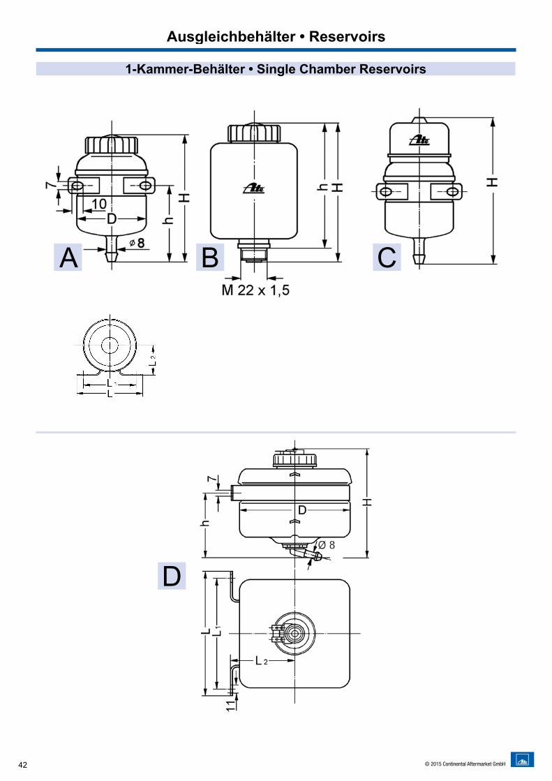
1-Kammer-Behälter • Single Chamber Reservoirs
Nennvolumen nominal volumes
V [l]
Ausführungversion
Maßedimensions [mm] Bemerkungen
remarksBestell-Nr.
part no.D H h L L1 L2
0,08A
5490
38 84 64 37 für Schlauchverbindung for hose connection
03.3508-1706.3C 114,5 03.3508-1712.3
0,13 B 6892 79,5
- - - zum Aufschrauben for screw connection
03.3508-0401.392,5 80 03.3508-0451.3 M
0,2 A 65
111,2
6784 64 37
für Schlauchverbindung for hose connection
03.3508-0264.3117 03.3508-0277.3 1
111,2 - - - 03.3508-0278.3 2111,8 84 64 37 03.3508-0281.3 M
0,35 B 78128 116
- - - zum Aufschrauben for screw connection
03.3508-0501.3142 130 03.3508-0503.3 1
128,2 115,7 03.3508-0551.3 M
0,5
A
80
151109
98 78 46
für Schlauchverbindung for hose connection
03.3508-4903.3152 03.3508-4905.3 M
160,5 03.3508-4906.3 1
A 3
168 126 mit Zwischenstück M18x1,5 with adapter M18x1,5 03.3509-0100.3
173 131
mit Zwischenstück Ø 9für Schlauchverbindung
with adapter Ø 9 for hose connection
03.3509-0600.3
1,0 D 130x130 131 78 181 160 76 für Schlauchverbindung for hose connection 03.3558-0001.3 1
Weitere Behälter auf Anfrage • more Reservoirs available on reqest
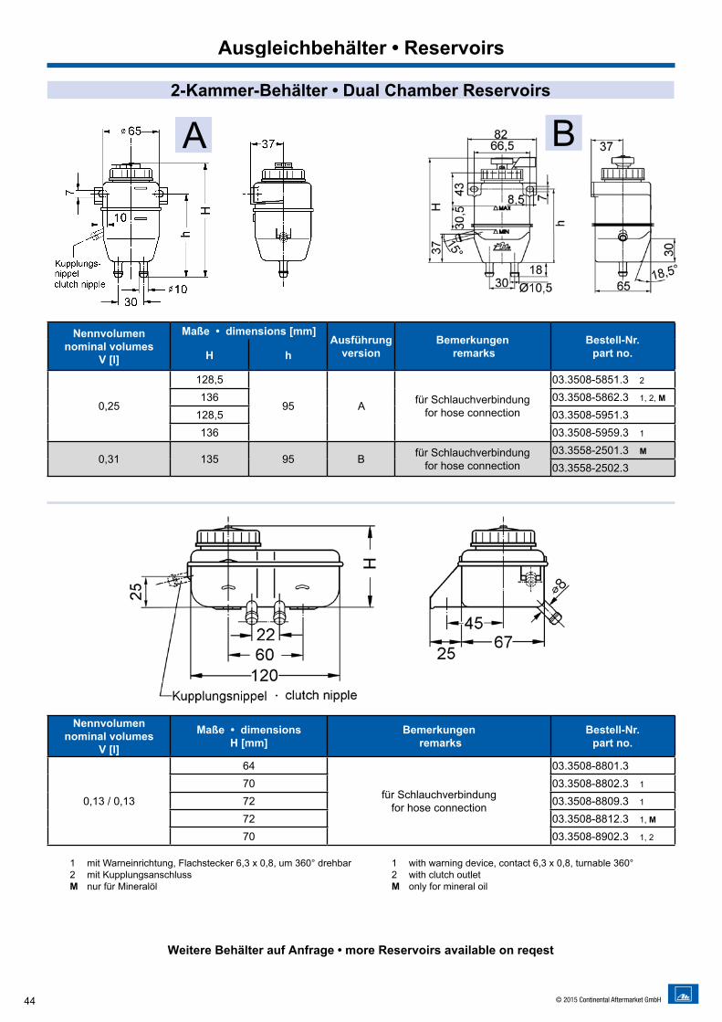
A B
44 © 2015 Continental Aftermarket GmbH
Ausgleichbehälter • Reservoirs
Nennvolumen nominal volumes
V [l]
Maße • dimensions [mm]Ausführung
versionBemerkungen
remarksBestell-Nr.
part no.H h
0,25
128,5
95 A für Schlauchverbindungfor hose connection
03.3508-5851.3 2
136 03.3508-5862.3 1, 2, M
128,5 03.3508-5951.3136 03.3508-5959.3 1
0,31 135 95 B für Schlauchverbindungfor hose connection
03.3558-2501.3 M
03.3558-2502.3
Nennvolumen nominal volumes
V [l]
Maße • dimensionsH [mm]
Bemerkungen remarks
Bestell-Nr.part no.
0,13 / 0,13
64
für Schlauchverbindungfor hose connection
03.3508-8801.370 03.3508-8802.3 1
72 03.3508-8809.3 1
72 03.3508-8812.3 1, M
70 03.3508-8902.3 1, 2
1 mit Warneinrichtung, Flachstecker 6,3 x 0,8, um 360° drehbar 2 mit Kupplungsanschluss M nur für Mineralöl
1 with warning device, contact 6,3 x 0,8, turnable 360°2 with clutch outletM only for mineral oil
Weitere Behälter auf Anfrage • more Reservoirs available on reqest
2-Kammer-Behälter • Dual Chamber Reservoirs
45© 2015 Continental Aftermarket GmbH
Ausgleichbehälter • Reservoirs
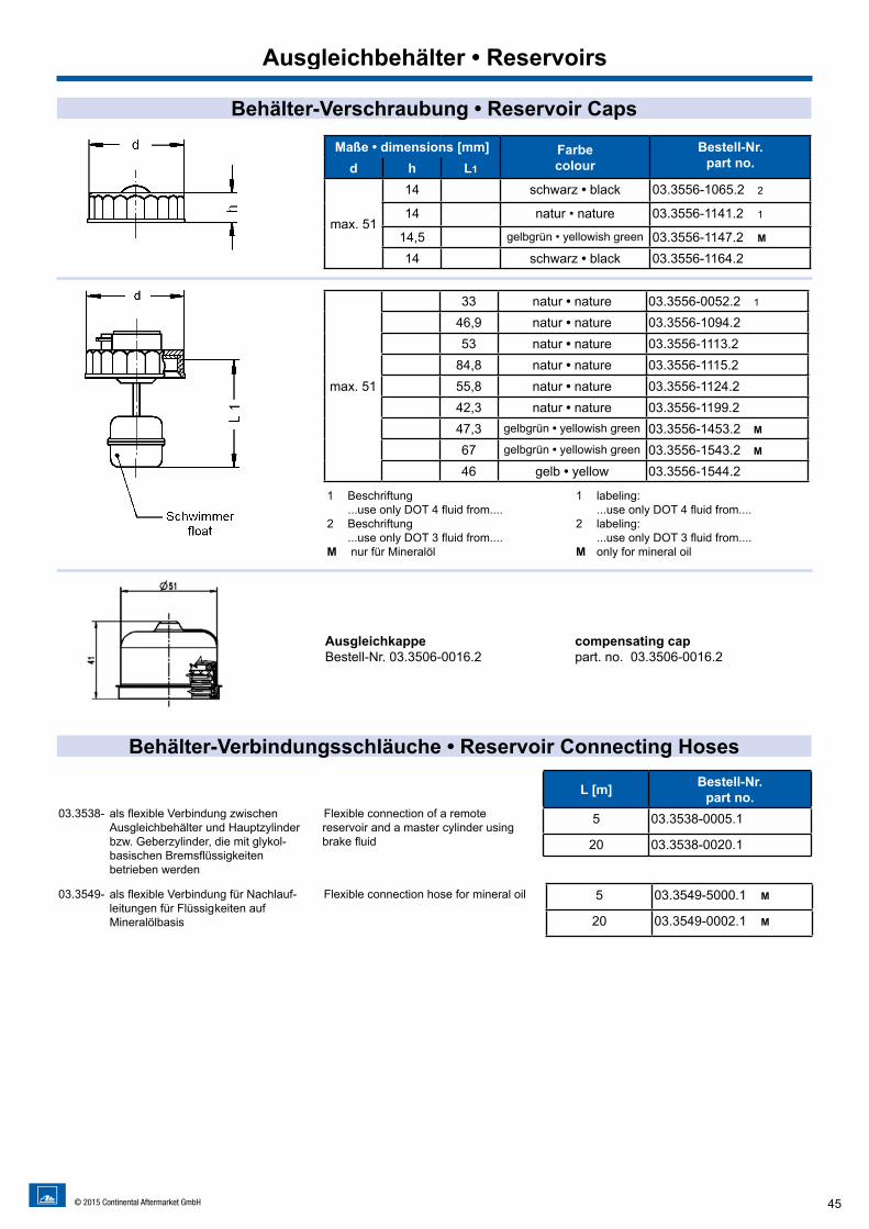
Behälter-Verschraubung • Reservoir Caps
Behälter-Verbindungsschläuche • Reservoir Connecting Hoses
Maße • dimensions [mm] Farbecolour
Bestell-Nr. part no.d h L1
max. 51
14 schwarz • black 03.3556-1065.2 2
14 natur • nature 03.3556-1141.2 1
14,5 gelbgrün • yellowish green 03.3556-1147.2 M
14 schwarz • black 03.3556-1164.2
max. 51
33 natur • nature 03.3556-0052.2 1
46,9 natur • nature 03.3556-1094.253 natur • nature 03.3556-1113.2
84,8 natur • nature 03.3556-1115.255,8 natur • nature 03.3556-1124.242,3 natur • nature 03.3556-1199.247,3 gelbgrün • yellowish green 03.3556-1453.2 M
67 gelbgrün • yellowish green 03.3556-1543.2 M
46 gelb • yellow 03.3556-1544.2
1 Beschriftung ...use only DOT 4 fluid from....
2 Beschriftung ...use only DOT 3 fluid from....
M nur für Mineralöl
1 labeling: ...use only DOT 4 fluid from....
2 labeling: ...use only DOT 3 fluid from....
M only for mineral oil
L [m] Bestell-Nr. part no.
5 03.3538-0005.1
20 03.3538-0020.1
5 03.3549-5000.1 M
20 03.3549-0002.1 M
03.3538- als flexible Verbindung zwischen Ausgleichbehälter und Hauptzylinder bzw. Geberzylinder, die mit glykol- basischen Bremsflüssigkeiten betrieben werden
Flexible connection of a remote reservoir and a master cylinder using brake fluid
03.3549- als flexible Verbindung für Nachlauf- leitungen für Flüssig keiten auf Mineralölbasis
Flexible connection hose for mineral oil
AusgleichkappeBestell-Nr. 03.3506-0016.2
compensating cappart. no. 03.3506-0016.2
46 © 2015 Continental Aftermarket GmbH
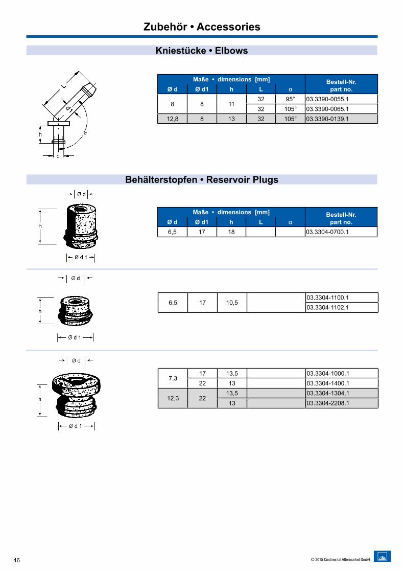
Kniestücke • Elbows
Zubehör • Accessories
Behälterstopfen • Reservoir Plugs
Maße • dimensions [mm] Bestell-Nr.part no.Ø d Ø d1 h L α
8 8 1132 95° 03.3390-0055.132 105° 03.3390-0065.1
12,8 8 13 32 105° 03.3390-0139.1
7,317 13,5 03.3304-1000.122 13 03.3304-1400.1
12,3 2213,5 03.3304-1304.113 03.3304-2208.1
6,5 17 10,5 03.3304-1100.103.3304-1102.1
Maße • dimensions [mm] Bestell-Nr.part no.Ø d Ø d1 h L α
6,5 17 18 03.3304-0700.1
47© 2015 Continental Aftermarket GmbH
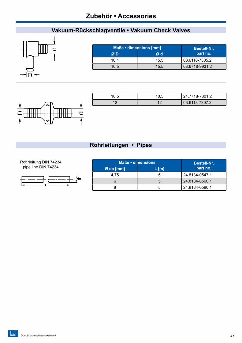
Zubehör • Accessories
Vakuum-Rückschlagventile • Vakuum Check Valves
Rohrleitungen • Pipes
Maße • dimensions [mm] Bestell-Nr.part no.Ø D Ø d
10,1 15,5 03.6118-7305.210,5 15,5 03.6718-9931.2
10,5 10,5 24.7718-7301.212 12 03.6118-7307.2
Maße • dimensions Bestell-Nr.part no.Ø da [mm] L [m]
4,75 5 24.8134-0547.16 5 24.8134-0560.18 5 24.8134-0580.1
Rohrleitung DIN 74234pipe line DIN 74234
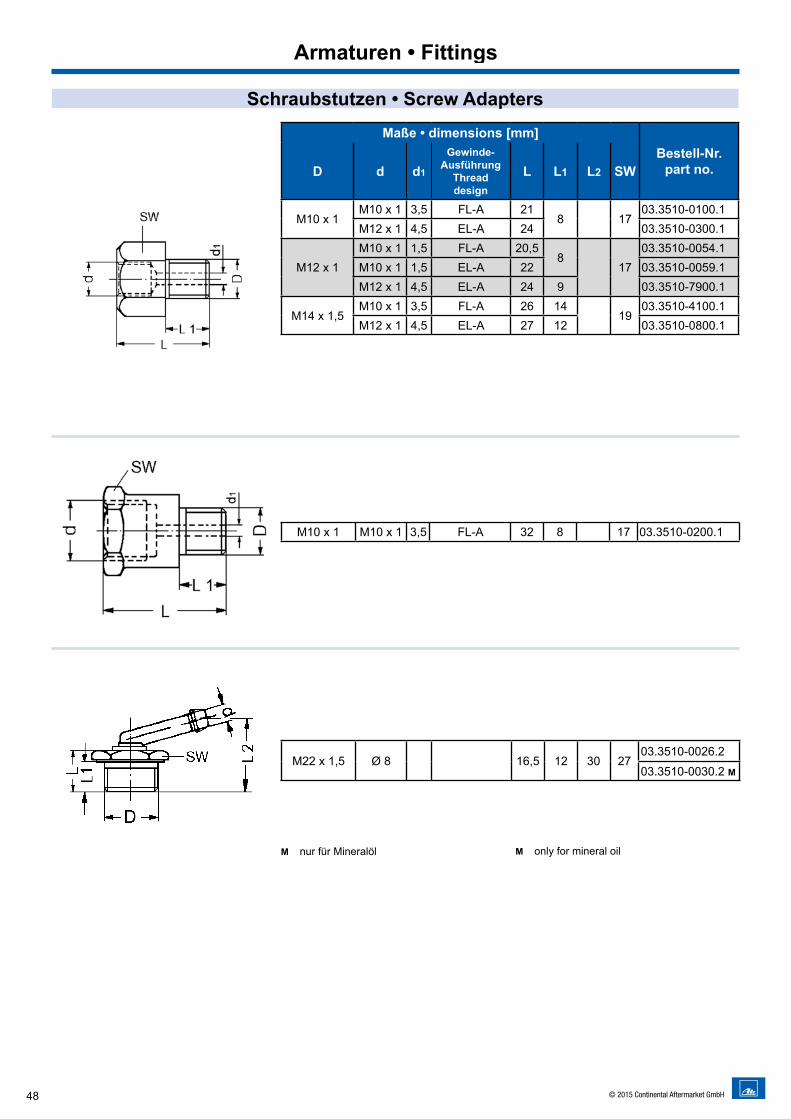
48 © 2015 Continental Aftermarket GmbH
Maße • dimensions [mm]Bestell-Nr.
part no.D d d1
Gewinde-Ausführung
Thread design
L L1 L2 SW
M10 x 1M10 x 1 3,5 FL-A 21
8 1703.3510-0100.1
M12 x 1 4,5 EL-A 24 03.3510-0300.1
M12 x 1M10 x 1 1,5 FL-A 20,5
817
03.3510-0054.1M10 x 1 1,5 EL-A 22 03.3510-0059.1M12 x 1 4,5 EL-A 24 9 03.3510-7900.1
M14 x 1,5M10 x 1 3,5 FL-A 26 14
1903.3510-4100.1
M12 x 1 4,5 EL-A 27 12 03.3510-0800.1
M10 x 1 M10 x 1 3,5 FL-A 32 8 17 03.3510-0200.1
M22 x 1,5 Ø 8 16,5 12 30 2703.3510-0026.2
03.3510-0030.2 M
M nur für Mineralöl M only for mineral oil
Schraubstutzen • Screw Adapters
Armaturen • Fittings
49© 2015 Continental Aftermarket GmbH
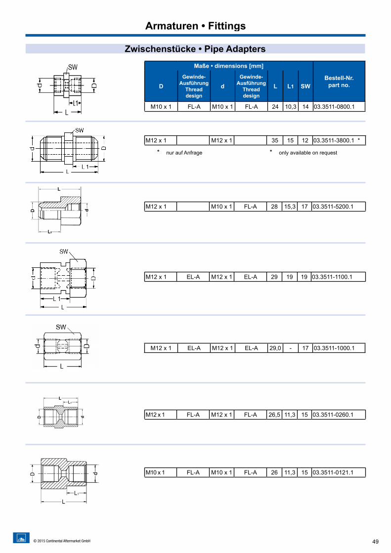
Zwischenstücke • Pipe Adapters
Armaturen • Fittings
Maße • dimensions [mm]
Bestell-Nr.part no.D
Gewinde-Ausführung
Thread design
dGewinde-
AusführungThread design
L L1 SW
M10 x 1 FL-A M10 x 1 FL-A 24 10,3 14 03.3511-0800.1
M12 x 1 M12 x 1 35 15 12 03.3511-3800.1 *
M12 x 1 M10 x 1 FL-A 28 15,3 17 03.3511-5200.1
M12 x 1 EL-A M12 x 1 EL-A 29 19 19 03.3511-1100.1
* nur auf Anfrage * only available on request
M12 x 1 EL-A M12 x 1 EL-A 29,0 - 17 03.3511-1000.1
M12 x 1 FL-A M12 x 1 FL-A 26,5 11,3 15 03.3511-0260.1
M10 x 1 FL-A M10 x 1 FL-A 26 11,3 15 03.3511-0121.1
50 © 2015 Continental Aftermarket GmbH
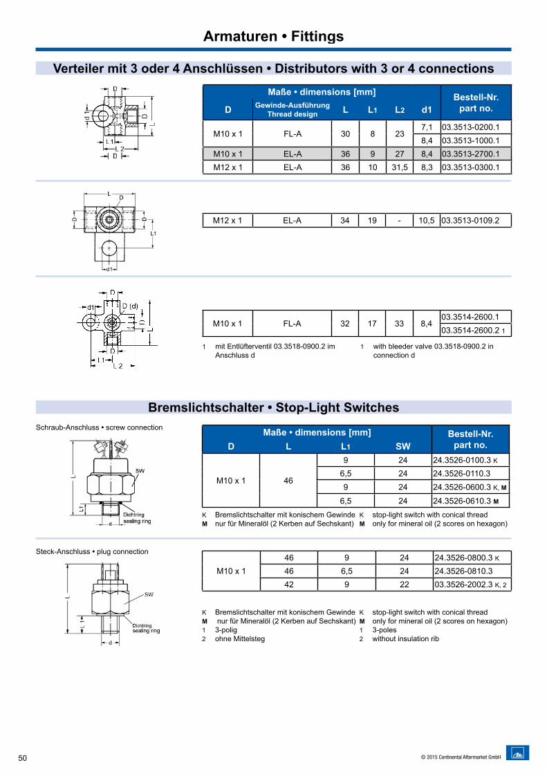
Verteiler mit 3 oder 4 Anschlüssen • Distributors with 3 or 4 connections
Bremslichtschalter • Stop-Light Switches
Maße • dimensions [mm] Bestell-Nr.part no.D Gewinde-Ausführung
Thread design L L1 L2 d1
M10 x 1 FL-A 30 8 237,1 03.3513-0200.18,4 03.3513-1000.1
M10 x 1 EL-A 36 9 27 8,4 03.3513-2700.1M12 x 1 EL-A 36 10 31,5 8,3 03.3513-0300.1
M12 x 1 EL-A 34 19 - 10,5 03.3513-0109.2
M10 x 1 FL-A 32 17 33 8,403.3514-2600.103.3514-2600.2 1
1 mit Entlüfterventil 03.3518-0900.2 im Anschluss d
1 with bleeder valve 03.3518-0900.2 in connection d
Maße • dimensions [mm] Bestell-Nr.part no.D L L1 SW
M10 x 1 46
9 24 24.3526-0100.3 K6,5 24 24.3526-0110.39 24 24.3526-0600.3 K, M
6,5 24 24.3526-0610.3 M
M10 x 146 9 24 24.3526-0800.3 K46 6,5 24 24.3526-0810.342 9 22 03.3526-2002.3 K, 2
K Bremslichtschalter mit konischem GewindeM nur für Mineralöl (2 Kerben auf Sechskant)
K stop-light switch with conical threadM only for mineral oil (2 scores on hexagon)
K Bremslichtschalter mit konischem GewindeM nur für Mineralöl (2 Kerben auf Sechskant)1 3-polig2 ohne Mittelsteg
K stop-light switch with conical threadM only for mineral oil (2 scores on hexagon)1 3-poles2 without insulation rib
Schraub-Anschluss • screw connection
Steck-Anschluss • plug connection
Armaturen • Fittings
51© 2015 Continental Aftermarket GmbH
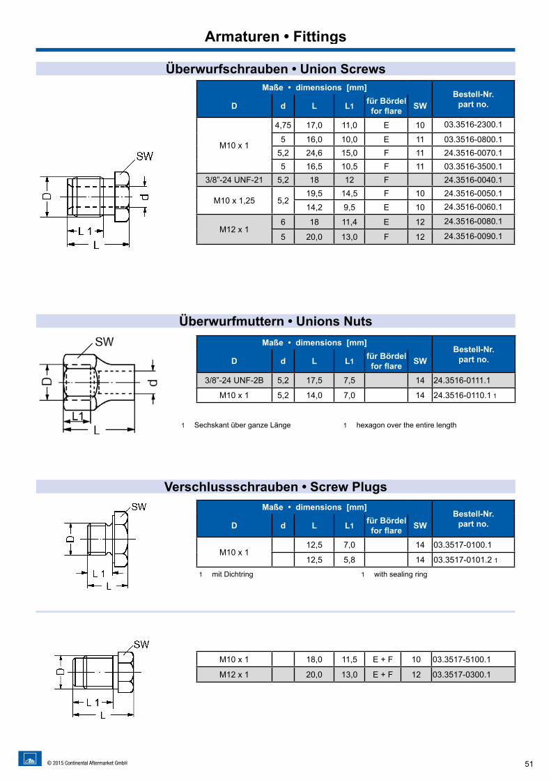
Überwurfschrauben • Union Screws
Überwurfmuttern • Unions Nuts
Verschlussschrauben • Screw Plugs
Maße • dimensions [mm]Bestell-Nr.
part no.D d L L1 für Bördelfor flare SW
M10 x 1
4,75 17,0 11,0 E 10 03.3516-2300.1
5 16,0 10,0 E 11 03.3516-0800.15,2 24,6 15,0 F 11 24.3516-0070.15 16,5 10,5 F 11 03.3516-3500.1
3/8”-24 UNF-21 5,2 18 12 F 24.3516-0040.1
M10 x 1,25 5,219,5 14,5 F 10 24.3516-0050.1
14,2 9,5 E 10 24.3516-0060.1
M12 x 16 18 11,4 E 12 24.3516-0080.1
5 20,0 13,0 F 12 24.3516-0090.1
1 Sechskant über ganze Länge 1 hexagon over the entire length
M10 x 1 18,0 11,5 E + F 10 03.3517-5100.1
M12 x 1 20,0 13,0 E + F 12 03.3517-0300.1
Armaturen • Fittings
1 mit Dichtring 1 with sealing ring
Maße • dimensions [mm]Bestell-Nr.
part no.D d L L1 für Bördelfor flare SW
3/8”-24 UNF-2B 5,2 17,5 7,5 14 24.3516-0111.1
M10 x 1 5,2 14,0 7,0 14 24.3516-0110.1 1
Maße • dimensions [mm]Bestell-Nr.
part no.D d L L1 für Bördelfor flare SW
M10 x 112,5 7,0 14 03.3517-0100.1
12,5 5,8 14 03.3517-0101.2 1
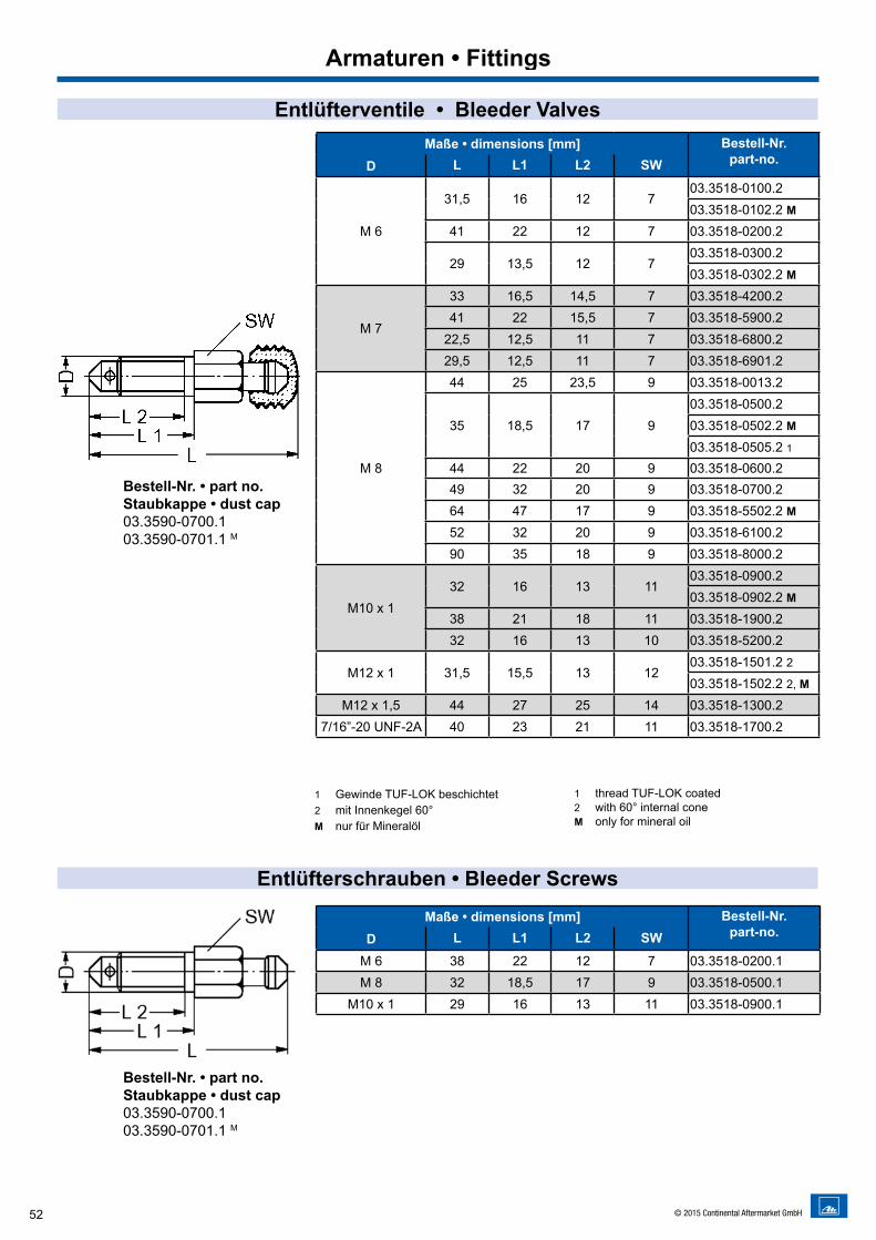
52 © 2015 Continental Aftermarket GmbH
Entlüfterventile • Bleeder ValvesMaße • dimensions [mm] Bestell-Nr.
part-no.D L L1 L2 SW
M 6
31,5 16 12 703.3518-0100.203.3518-0102.2 M
41 22 12 7 03.3518-0200.2
29 13,5 12 703.3518-0300.203.3518-0302.2 M
M 7
33 16,5 14,5 7 03.3518-4200.241 22 15,5 7 03.3518-5900.2
22,5 12,5 11 7 03.3518-6800.229,5 12,5 11 7 03.3518-6901.2
M 8
44 25 23,5 9 03.3518-0013.2
35 18,5 17 903.3518-0500.203.3518-0502.2 M03.3518-0505.2 1
44 22 20 9 03.3518-0600.249 32 20 9 03.3518-0700.264 47 17 9 03.3518-5502.2 M52 32 20 9 03.3518-6100.290 35 18 9 03.3518-8000.2
M10 x 132 16 13 11
03.3518-0900.203.3518-0902.2 M
38 21 18 11 03.3518-1900.232 16 13 10 03.3518-5200.2
M12 x 1 31,5 15,5 13 1203.3518-1501.2 203.3518-1502.2 2, M
M12 x 1,5 44 27 25 14 03.3518-1300.27/16”-20 UNF-2A 40 23 21 11 03.3518-1700.2
1 Gewinde TUF-LOK beschichtet2 mit Innenkegel 60°M nur für Mineralöl
1 thread TUF-LOK coated 2 with 60° internal coneM only for mineral oil
Entlüfterschrauben • Bleeder Screws
Bestell-Nr. • part no.Staubkappe • dust cap03.3590-0700.103.3590-0701.1 M
Armaturen • Fittings
Maße • dimensions [mm] Bestell-Nr. part-no.D L L1 L2 SW
M 6 38 22 12 7 03.3518-0200.1M 8 32 18,5 17 9 03.3518-0500.1
M10 x 1 29 16 13 11 03.3518-0900.1
Bestell-Nr. • part no.Staubkappe • dust cap03.3590-0700.103.3590-0701.1 M
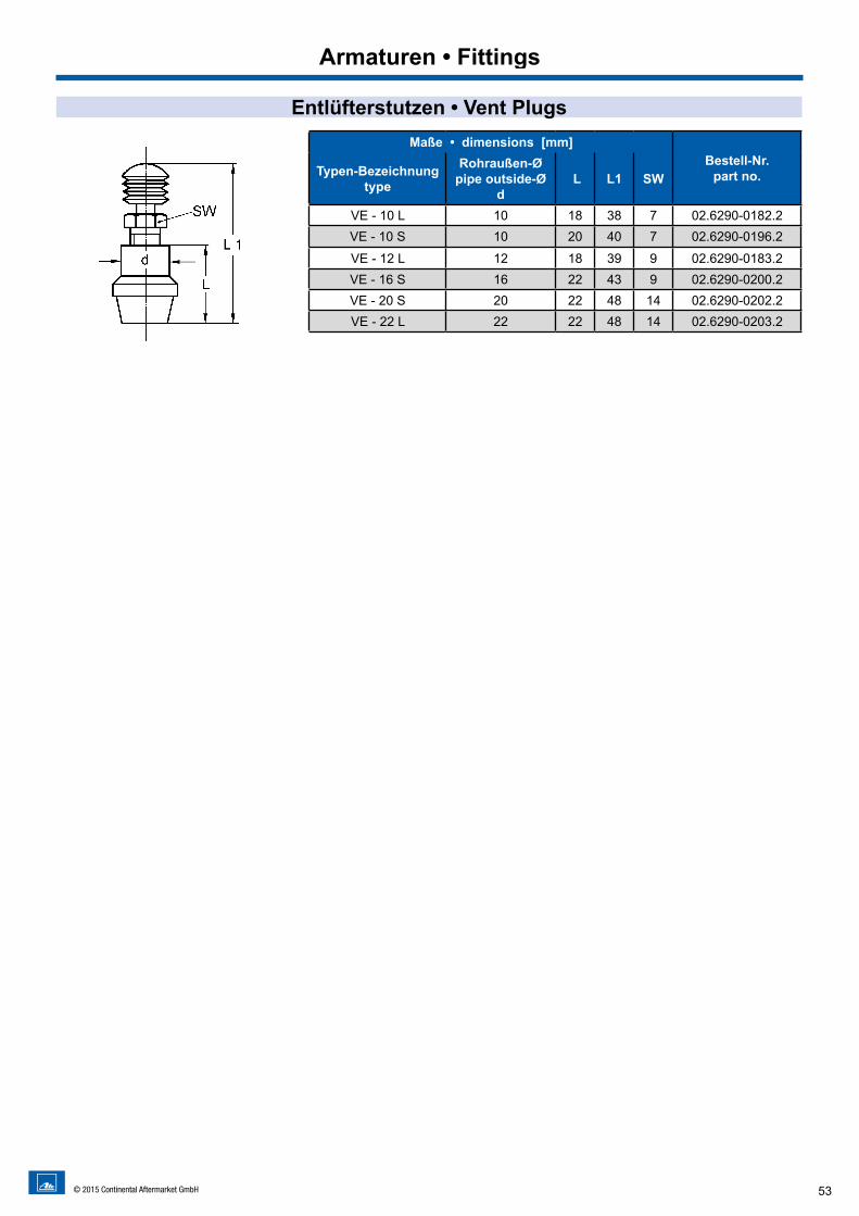
53© 2015 Continental Aftermarket GmbH
Entlüfterstutzen • Vent PlugsMaße • dimensions [mm]
Bestell-Nr.part no.Typen-Bezeichnung
type
Rohraußen-Øpipe outside-Ø
d L L1 SW
VE - 10 L 10 18 38 7 02.6290-0182.2VE - 10 S 10 20 40 7 02.6290-0196.2
VE - 12 L 12 18 39 9 02.6290-0183.2VE - 16 S 16 22 43 9 02.6290-0200.2VE - 20 S 20 22 48 14 02.6290-0202.2VE - 22 L 22 22 48 14 02.6290-0203.2
Armaturen • Fittings
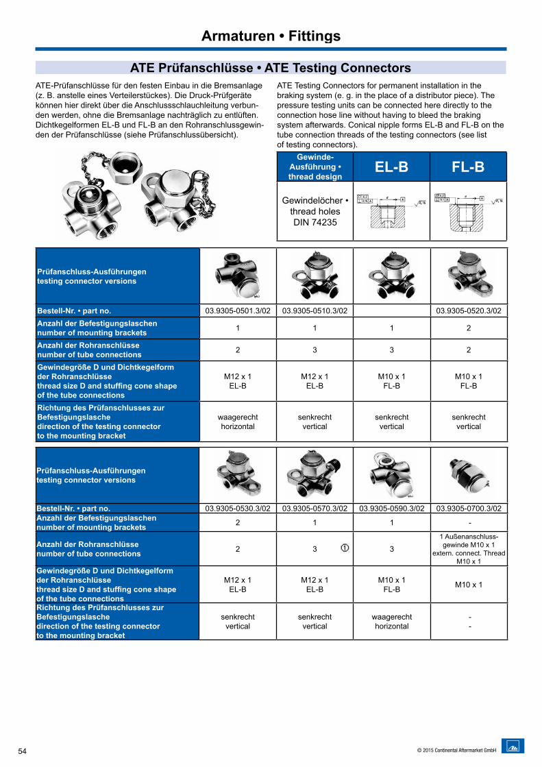
54 © 2015 Continental Aftermarket GmbH
Armaturen • Fittings
ATE Prüfanschlüsse • ATE Testing ConnectorsATE-Prüfanschlüsse für den festen Einbau in die Bremsanlage (z. B. anstelle eines Verteilerstückes). Die Druck-Prüfgeräte können hier direkt über die Anschlussschlauchleitung verbun-den werden, ohne die Bremsanlage nachträglich zu entlüften.Dichtkegelformen EL-B und FL-B an den Rohranschlussgewin-den der Prüfanschlüsse (siehe Prüfanschlussübersicht).
ATE Testing Connectors for permanent installation in the braking system (e. g. in the place of a distributor piece). The pressure testing units can be connected here directly to the connection hose line without having to bleed the braking system afterwards. Conical nipple forms EL-B and FL-B on the tube connection threads of the testing connectors (see list of testing connectors).
Gewinde-Ausführung • thread design
EL-B FL-B
Gewindelöcher •thread holesDIN 74235
Prüfanschluss-Ausführungentesting connector versions ^^
Bestell-Nr. • part no. 03.9305-0501.3/02 03.9305-0510.3/02 03.9305-0520.3/02Anzahl der Befestigungslaschennumber of mounting brackets 1 1 1 2
Anzahl der Rohranschlüssenumber of tube connections 2 3 3 2
Gewindegröße D und Dichtkegelformder Rohranschlüssethread size D and stuffing cone shapeof the tube connections
M12 x 1EL-B
M12 x 1EL-B
M10 x 1FL-B
M10 x 1FL-B
Richtung des Prüfanschlusses zurBefestigungslaschedirection of the testing connectorto the mounting bracket
waagerechthorizontal
senkrechtvertical
senkrecht vertical
senkrechtvertical
Prüfanschluss-Ausführungentesting connector versions
Bestell-Nr. • part no. 03.9305-0530.3/02 03.9305-0570.3/02 03.9305-0590.3/02 03.9305-0700.3/02Anzahl der Befestigungslaschennumber of mounting brackets 2 1 1 -
Anzahl der Rohranschlüssenumber of tube connections 2 3 3
1 Außenanschluss-gewinde M10 x 1
extern. connect. Thread M10 x 1
Gewindegröße D und Dichtkegelformder Rohranschlüssethread size D and stuffing cone shapeof the tube connections
M12 x 1EL-B
M12 x 1EL-B
M10 x 1FL-B M10 x 1
Richtung des Prüfanschlusses zurBefestigungslaschedirection of the testing connectorto the mounting bracket
senkrechtvertical
senkrechtvertical
waagerechthorizontal
- -
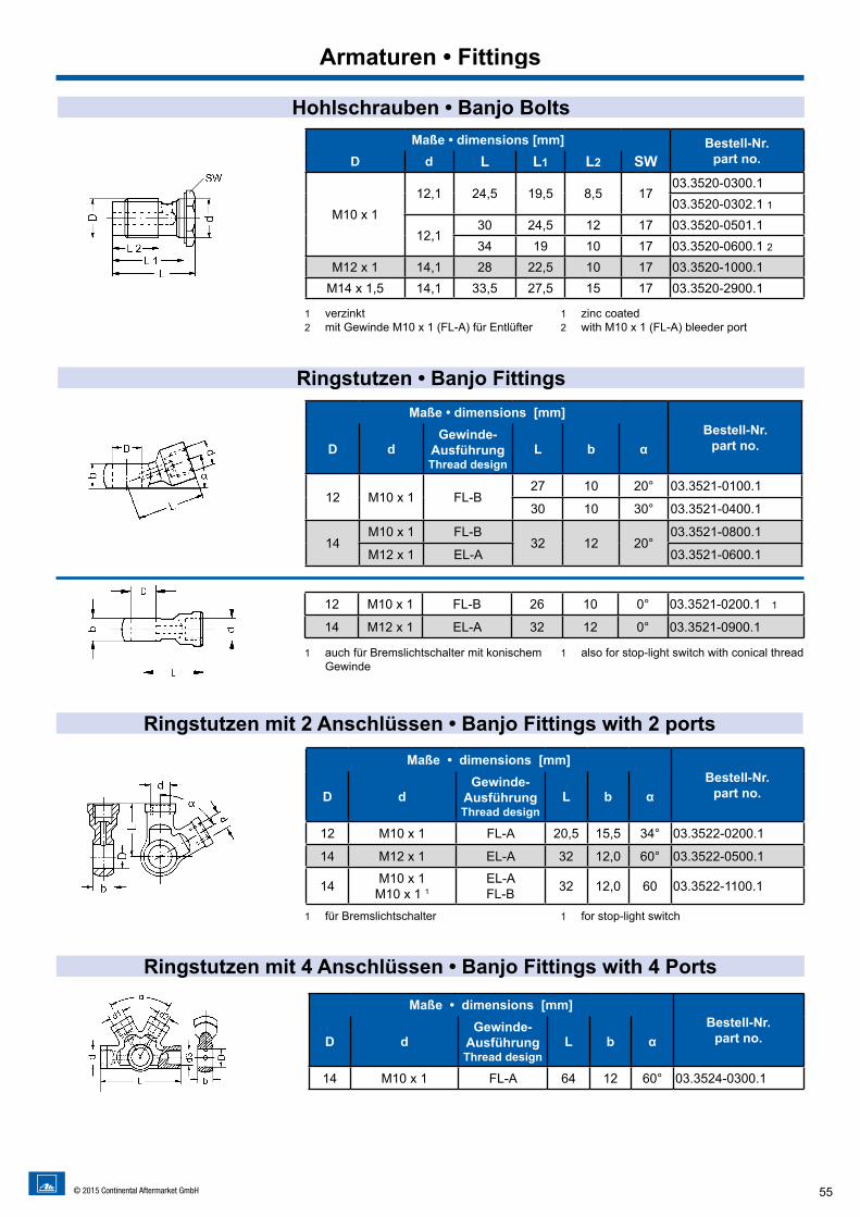
55© 2015 Continental Aftermarket GmbH
Hohlschrauben • Banjo Bolts
Ringstutzen • Banjo Fittings
Maße • dimensions [mm] Bestell-Nr.part no.D d L L1 L2 SW
M10 x 112,1 24,5 19,5 8,5 17
03.3520-0300.103.3520-0302.1 1
12,130 24,5 12 17 03.3520-0501.134 19 10 17 03.3520-0600.1 2
M12 x 1 14,1 28 22,5 10 17 03.3520-1000.1M14 x 1,5 14,1 33,5 27,5 15 17 03.3520-2900.1
1 verzinkt 2 mit Gewinde M10 x 1 (FL-A) für Entlüfter
1 zinc coated2 with M10 x 1 (FL-A) bleeder port
Maße • dimensions [mm]Bestell-Nr.
part no.D dGewinde-
AusführungThread design
L b α
12 M10 x 1 FL-B27 10 20° 03.3521-0100.1
30 10 30° 03.3521-0400.1
14M10 x 1 FL-B
32 12 20°03.3521-0800.1
M12 x 1 EL-A 03.3521-0600.1
12 M10 x 1 FL-B 26 10 0° 03.3521-0200.1 1
14 M12 x 1 EL-A 32 12 0° 03.3521-0900.1
1 auch für Bremslichtschalter mit konischem Gewinde
1 also for stop-light switch with conical thread
Armaturen • Fittings
Ringstutzen mit 2 Anschlüssen • Banjo Fittings with 2 ports
Ringstutzen mit 4 Anschlüssen • Banjo Fittings with 4 Ports
Maße • dimensions [mm]Bestell-Nr.
part no.D dGewinde-
AusführungThread design
L b α
12 M10 x 1 FL-A 20,5 15,5 34° 03.3522-0200.1
14 M12 x 1 EL-A 32 12,0 60° 03.3522-0500.1
14 M10 x 1M10 x 1 1
EL-AFL-B 32 12,0 60 03.3522-1100.1
Maße • dimensions [mm]Bestell-Nr.
part no.D dGewinde-
AusführungThread design
L b α
14 M10 x 1 FL-A 64 12 60° 03.3524-0300.1
1 für Bremslichtschalter 1 for stop-light switch
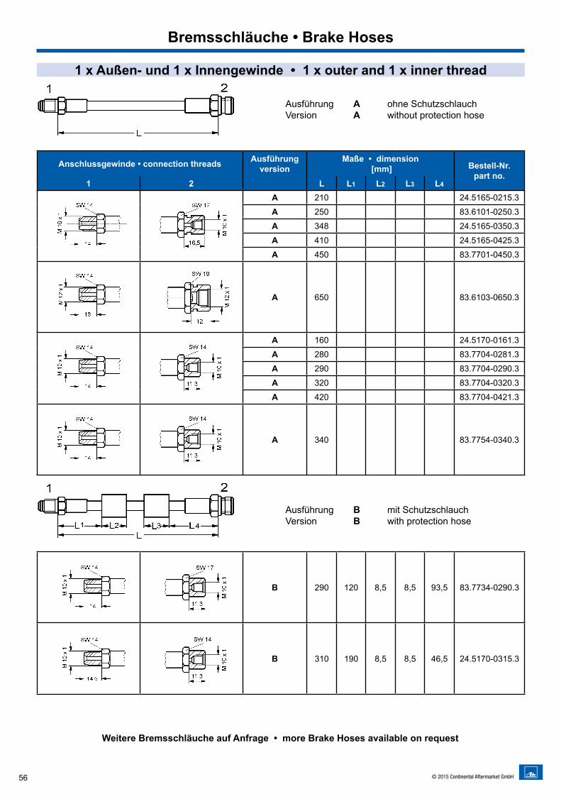
56 © 2015 Continental Aftermarket GmbH
1 x Außen- und 1 x Innengewinde • 1 x outer and 1 x inner thread
Weitere Bremsschläuche auf Anfrage • more Brake Hoses available on request
Ausführung A ohne SchutzschlauchVersion A without protection hose
Ausführung B mit SchutzschlauchVersion B with protection hose
Bremsschläuche • Brake Hoses
Anschlussgewinde • connection threads Ausführungversion
Maße • dimension [mm] Bestell-Nr.
part no.1 2 L L1 L2 L3 L4
A 210 24.5165-0215.3
A 250 83.6101-0250.3
A 348 24.5165-0350.3
A 410 24.5165-0425.3
A 450 83.7701-0450.3
A 650 83.6103-0650.3
A 160 24.5170-0161.3
A 280 83.7704-0281.3
A 290 83.7704-0290.3
A 320 83.7704-0320.3
A 420 83.7704-0421.3
A 340 83.7754-0340.3
B 290 120 8,5 8,5 93,5 83.7734-0290.3
B 310 190 8,5 8,5 46,5 24.5170-0315.3
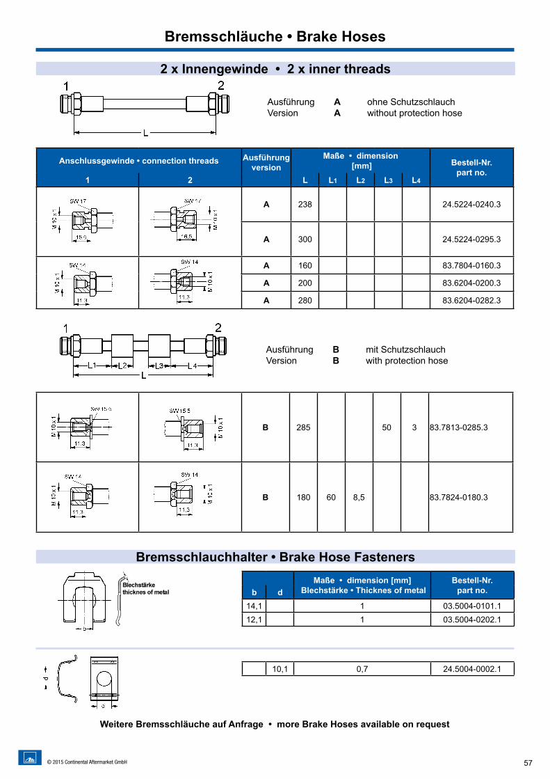
B 285 50 3 83.7813-0285.3
B 180 60 8,5 83.7824-0180.3
57© 2015 Continental Aftermarket GmbH
2 x Innengewinde • 2 x inner threads
Ausführung A ohne SchutzschlauchVersion A without protection hose
Ausführung B mit SchutzschlauchVersion B with protection hose
Bremsschlauchhalter • Brake Hose Fasteners
Weitere Bremsschläuche auf Anfrage • more Brake Hoses available on request
Maße • dimension [mm] Blechstärke • Thicknes of metal
Bestell-Nr.part no.b d
14,1 1 03.5004-0101.112,1 1 03.5004-0202.1
10,1 0,7 24.5004-0002.1
Bremsschläuche • Brake Hoses
Anschlussgewinde • connection threads Ausführungversion
Maße • dimension [mm] Bestell-Nr.
part no.1 2 L L1 L2 L3 L4
A 238 24.5224-0240.3
A 300 24.5224-0295.3
A 160 83.7804-0160.3
A 200 83.6204-0200.3
A 280 83.6204-0282.3
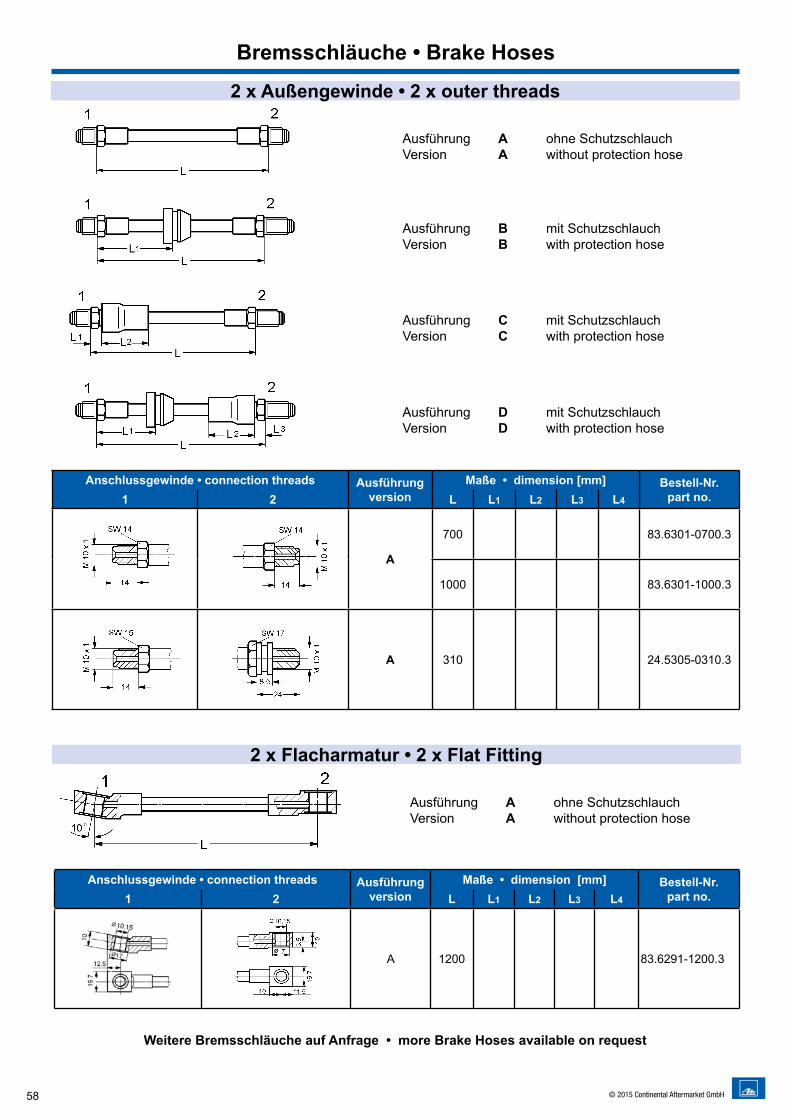
58 © 2015 Continental Aftermarket GmbH
Ausführung A ohne SchutzschlauchVersion A without protection hose
Ausführung B mit SchutzschlauchVersion B with protection hose
Ausführung C mit SchutzschlauchVersion C with protection hose
Ausführung D mit SchutzschlauchVersion D with protection hose
Weitere Bremsschläuche auf Anfrage • more Brake Hoses available on request
Bremsschläuche • Brake Hoses
Anschlussgewinde • connection threads Ausführungversion
Maße • dimension [mm] Bestell-Nr.part no.1 2 L L1 L2 L3 L4
A
700 83.6301-0700.3
1000 83.6301-1000.3
A 310 24.5305-0310.3
Anschlussgewinde • connection threads Ausführungversion
Maße • dimension [mm] Bestell-Nr.part no.1 2 L L1 L2 L3 L4
A 1200 83.6291-1200.3
2 x Flacharmatur • 2 x Flat Fitting
Ausführung A ohne SchutzschlauchVersion A without protection hose
2 x Außengewinde • 2 x outer threads
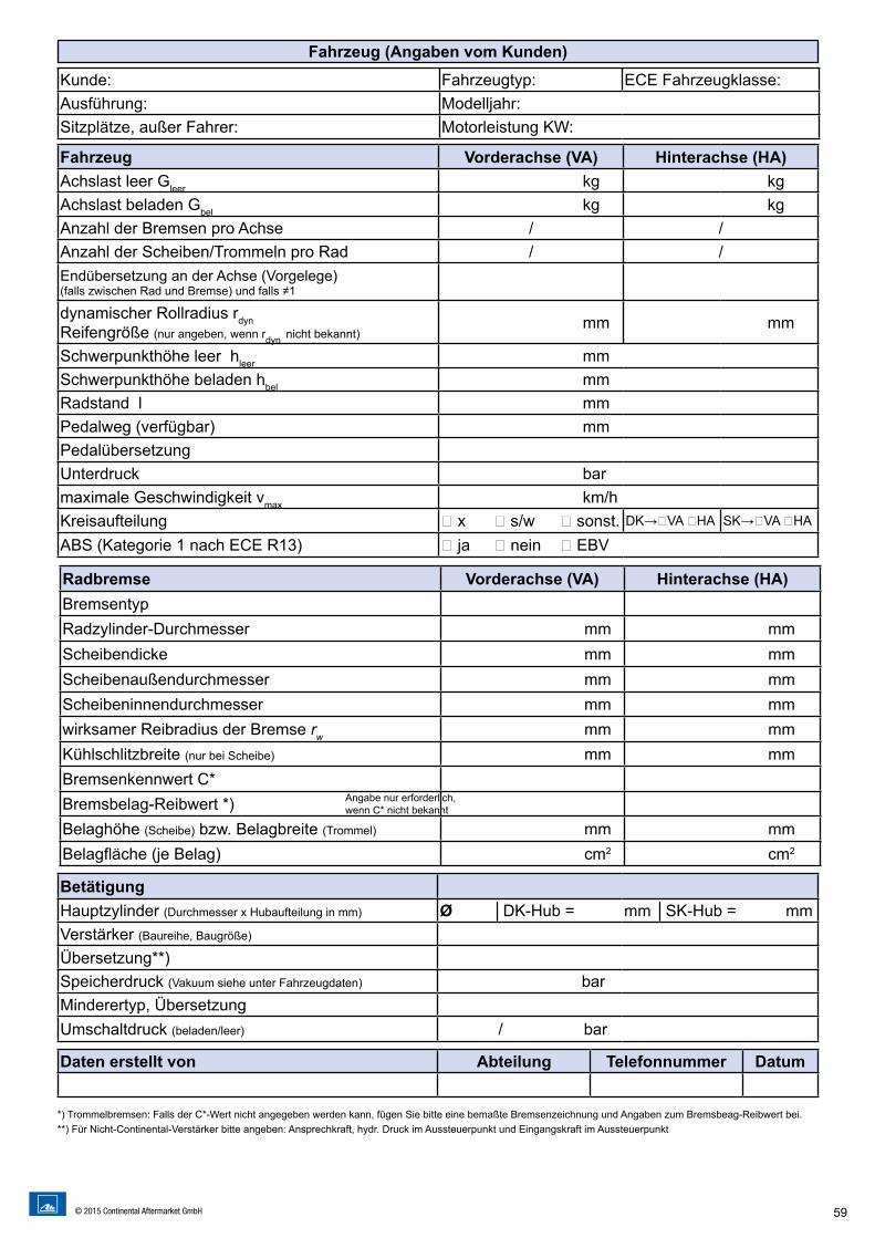
59© 2015 Continental Aftermarket GmbH
Fahrzeug (Angaben vom Kunden)
Kunde: Fahrzeugtyp: ECE Fahrzeugklasse:Ausführung: Modelljahr:Sitzplätze, außer Fahrer: Motorleistung KW:
Fahrzeug Vorderachse (VA) Hinterachse (HA)Achslast leer Gleer kg kgAchslast beladen Gbel kg kgAnzahl der Bremsen pro Achse / /Anzahl der Scheiben/Trommeln pro Rad / /Endübersetzung an der Achse (Vorgelege)(falls zwischen Rad und Bremse) und falls ≠1
dynamischer Rollradius rdynReifengröße (nur angeben, wenn rdyn nicht bekannt) mm mm
Schwerpunkthöhe leer hleer mmSchwerpunkthöhe beladen hbel mmRadstand l mmPedalweg (verfügbar) mmPedalübersetzungUnterdruck barmaximale Geschwindigkeit vmax km/hKreisaufteilung � x � s/w � sonst. DK→�VA �HA SK→�VA �HA
ABS (Kategorie 1 nach ECE R13) � ja � nein � EBV
BetätigungHauptzylinder (Durchmesser x Hubaufteilung in mm) Ø │DK-Hub = mm │SK-Hub = mmVerstärker (Baureihe, Baugröße)
Übersetzung**)Speicherdruck (Vakuum siehe unter Fahrzeugdaten) barMinderertyp, ÜbersetzungUmschaltdruck (beladen/leer) / bar
Daten erstellt von Abteilung Telefonnummer Datum
Radbremse Vorderachse (VA) Hinterachse (HA)BremsentypRadzylinder-Durchmesser mm mmScheibendicke mm mmScheibenaußendurchmesser mm mmScheibeninnendurchmesser mm mmwirksamer Reibradius der Bremse rw mm mmKühlschlitzbreite (nur bei Scheibe) mm mmBremsenkennwert C*Bremsbelag-Reibwert *) Belaghöhe (Scheibe) bzw. Belagbreite (Trommel) mm mmBelagfläche (je Belag) cm2 cm2
Angabe nur erforderlich, wenn C* nicht bekannt
*) Trommelbremsen: Falls der C*-Wert nicht angegeben werden kann, fügen Sie bitte eine bemaßte Bremsenzeichnung und Angaben zum Bremsbeag-Reibwert bei.**) Für Nicht-Continental-Verstärker bitte angeben: Ansprechkraft, hydr. Druck im Aussteuerpunkt und Eingangskraft im Aussteuerpunkt
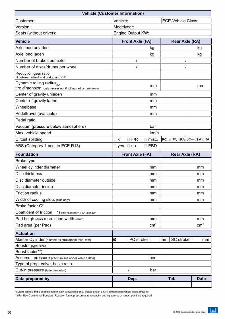
60 © 2015 Continental Aftermarket GmbH
Foundation Front Axle (FA) Rear Axle (RA)Brake typeWheel cylinder diameter mm mmDisc thickness mm mmDisc diameter outside mm mmDisc diameter inside mm mmFriction radius mm mmWidth of cooling slots (disc only) mm mmBrake factor C*Coefficent of friction *) only necessary, if C* unknown
Pad heigh (disc) resp. shoe width (drum) mm mmPad area (per Pad) cm2 cm2
Vehicle (Customer Information)
Customer: Vehicle: ECE-Vehicle Class:Version: Modelyear:Seats (without driver): Engine Output KW:
Vehicle Front Axle (FA) Rear Axle (RA)Axle load unladen kg kgAxle load laden kg kgNumber of brakes per axle / /Number of discs/drums per wheel / /Reduction gear ratio(if between wheel and brake) and if ≠1
Dynamic rolling radiusdyntire dimension (only necessary, if rolling radius unknown)
mm mm
Center of gravity unladen mmCenter of gravity laden mmWheelbase mmPedaltravel (available) mmPedal ratioVacuum (pressure below atmosphere) barMax. vehicle speed km/hCircuit splitting � x � F/R � misc. PC→�FA �RA SC→�FA �RA
ABS (Category 1 acc. to ECE R13) � yes � no � EBD
*) Drum Brakes: If the coefficient of friction is available only, please attach a fully dimensioned wheel brake drawing.**) For Non-Ate Boosters: Reaction force, pressure at runout point and input force at runout point are required.
ActuationMaster Cylinder (diameter x stroke(prim./sec. mm) Ø │PC stroke = mm │SC stroke = mmBooster (type, size)
Boost factor**)Accumul. pressure (vacuum see under vehicle data) barType of prop. valve, basic ratioCut-in pressure (laden/unladen) / bar
Data prepared by Dep. Tel. Date
*) Drum Brakes: If the coefficient of friction is available only, please attach a fully dimensioned wheel brake drawing.**) For Non-Continental-Boosters: Reaction force, pressure at runout point and input force at runout point are required.
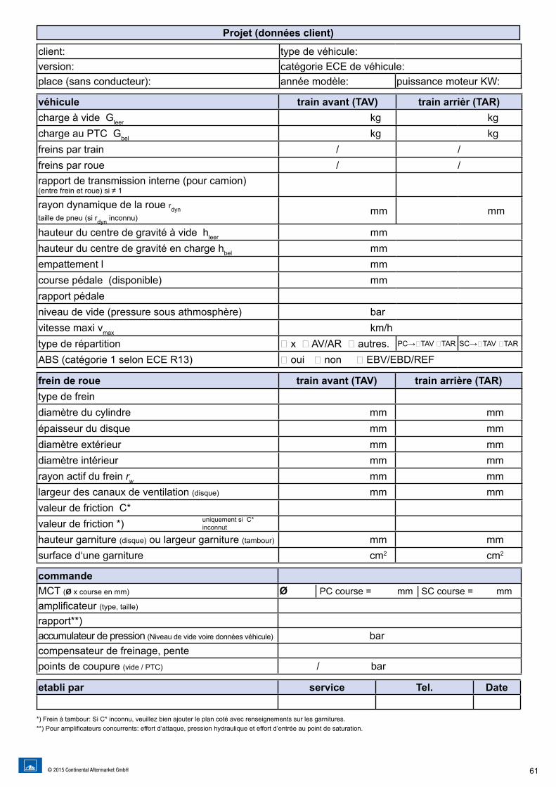
61© 2015 Continental Aftermarket GmbH
Projet (données client)
frein de roue train avant (TAV) train arrière (TAR)type de freindiamètre du cylindre mm mmépaisseur du disque mm mmdiamètre extérieur mm mmdiamètre intérieur mm mmrayon actif du frein rw mm mmlargeur des canaux de ventilation (disque) mm mmvaleur de friction C*valeur de friction *) hauteur garniture (disque) ou largeur garniture (tambour) mm mmsurface d‘une garniture cm2 cm2
client: type de véhicule:version: catégorie ECE de véhicule:place (sans conducteur): année modèle: puissance moteur KW:
véhicule train avant (TAV) train arrièr (TAR)charge à vide Gleer kg kgcharge au PTC Gbel kg kgfreins par train / /freins par roue / /rapport de transmission interne (pour camion)(entre frein et roue) si ≠ 1
rayon dynamique de la roue rdyntaille de pneu (si rdyn inconnu) mm mm
hauteur du centre de gravité à vide hleer mmhauteur du centre de gravité en charge hbel mmempattement l mmcourse pédale (disponible) mmrapport pédaleniveau de vide (pressure sous athmosphère) barvitesse maxi vmax km/htype de répartition � x � AV/AR � autres. PC→�TAV �TAR SC→�TAV �TAR
ABS (catégorie 1 selon ECE R13) � oui � non � EBV/EBD/REF
uniquement si C* inconnut
commandeMCT (Ø x course en mm) Ø │PC course = mm │SC course = mmamplificateur (type, taille)
rapport**)accumulateur de pression (Niveau de vide voire données véhicule) barcompensateur de freinage, pentepoints de coupure (vide / PTC) / bar
etabli par service Tel. Date
*) Frein à tambour: Si C* inconnu, veuillez bien ajouter le plan coté avec renseignements sur les garnitures.**) Pour amplificateurs concurrents: effort d‘attaque, pression hydraulique et effort d‘entrée au point de saturation.
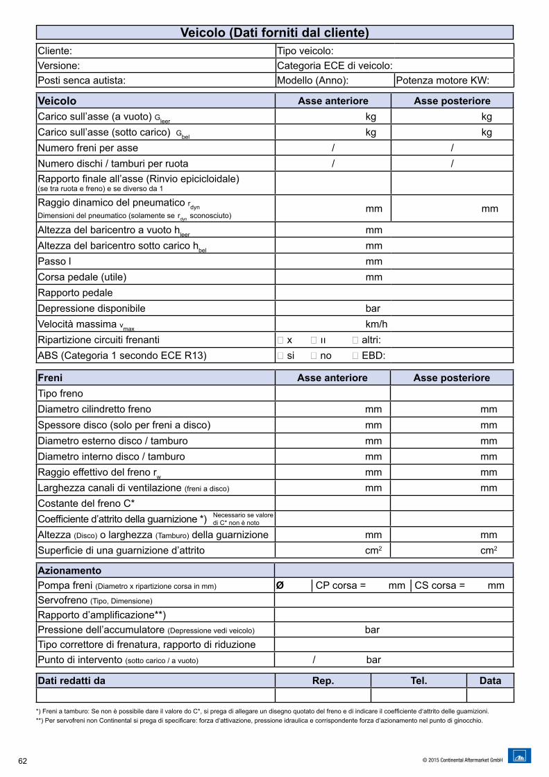
62 © 2015 Continental Aftermarket GmbH
Veicolo (Dati forniti dal cliente)
Freni Asse anteriore Asse posterioreTipo frenoDiametro cilindretto freno mm mmSpessore disco (solo per freni a disco) mm mmDiametro esterno disco / tamburo mm mmDiametro interno disco / tamburo mm mmRaggio effettivo del freno rw mm mmLarghezza canali di ventilazione (freni a disco) mm mmCostante del freno C*Coefficiente d’attrito della guarnizione *) Altezza (Disco) o larghezza (Tamburo) della guarnizione mm mmSuperficie di una guarnizione d’attrito cm2 cm2
Cliente: Tipo veicolo: Versione: Categoria ECE di veicolo:Posti senca autista: Modello (Anno): Potenza motore KW:
Veicolo Asse anteriore Asse posterioreCarico sull’asse (a vuoto) Gleer kg kgCarico sull’asse (sotto carico) Gbel kg kgNumero freni per asse / /Numero dischi / tamburi per ruota / /Rapporto finale all’asse (Rinvio epicicloidale)(se tra ruota e freno) e se diverso da 1
Raggio dinamico del pneumatico rdynDimensioni del pneumatico (solamente se rdyn sconosciuto) mm mm
Altezza del baricentro a vuoto hleer mmAltezza del baricentro sotto carico hbel mmPasso l mmCorsa pedale (utile) mmRapporto pedaleDepressione disponibile barVelocità massima vmax km/hRipartizione circuiti frenanti � x � ıı � altri:ABS (Categoria 1 secondo ECE R13) � si � no � EBD:
Necessario se valore di C* non è noto
AzionamentoPompa freni (Diametro x ripartizione corsa in mm) Ø │CP corsa = mm │CS corsa = mmServofreno (Tipo, Dimensione)
Rapporto d’amplificazione**)Pressione dell’accumulatore (Depressione vedi veicolo) barTipo correttore di frenatura, rapporto di riduzionePunto di intervento (sotto carico / a vuoto) / bar
Dati redatti da Rep. Tel. Data
*) Freni a tamburo: Se non è possibile dare il valore do C*, si prega di allegare un disegno quotato del freno e di indicare il coefficiente d‘attrito delle guamizioni.**) Per servofreni non Continental si prega di specificare: forza d‘attivazione, pressione idraulica e corrispondente forza d‘azionamento nel punto di ginocchio.

63© 2015 Continental Aftermarket GmbH

64 © 2015 Continental Aftermarket GmbH

Titelseite 210 mm
Bremsenkomponenten und BremssystemeBrake Components and Brake Systems
für Spezialserien und Nutzfahrzeugefor Special Series and Commercial Vehicles
SVB15
ATE – A Trademark of the Continental Corporation
Postfach 90 01 20 · D-60441 Frankfurt a. M. Tel. +49 (0) 69 7603-1 · Fax +49 (0) 69 761061
www.ate.de©20
15 C
ontin
enta
l Aft
erm
arke
t Gm
bH
Rückseite 210 mm