Embed Size (px)
Citation preview
Technische DatenTechnical Data
2
RADOLID-Kappen: Schutz und Sicherheit, im Test bewiesen!RADOLID Caps: Protection and safety, proven in the test!
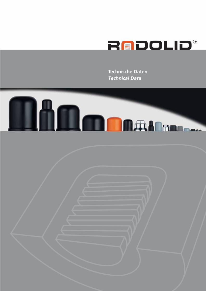
Der Salznebelsprühtest
Das Ergebnis nach1296 Stunden Dauertest:Im Gegensatz zur ersten,ungeschützten Reihe kannbei den, durch verschiedeneKappentypen (von links nachrechts: Serie SW, Serie BM,Serie ASW) geschütztenVerschraubungen nurgeringfügige Korrosionfestgestellt werden.
Korrosionstest CASSnach DIN 500211296 Stunden Dauertest
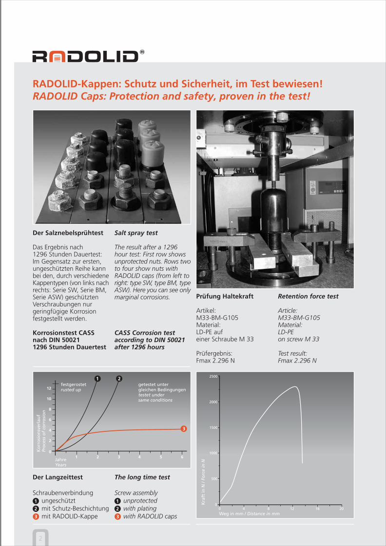
Prüfung Haltekraft
Artikel:M33-BM-G105Material:LD-PE aufeiner Schraube M 33
Prüfergebnis:Fmax 2.296 N
2
4
6
8
10
12
01 2 3 4 5 6
JahreYears
Ko
rro
sio
nsv
erla
uf
Pro
cess
of
corr
osi
on
festgerostetrusted up
1 2getestet untergleichen Bedingungentestet undersame conditions
Der Langzeittest
Schraubenverbindungungeschütztmit Schutz-Beschichtungmit RADOLID-Kappe
1
2
3
3
The long time test
Screw assemblyunprotectedwith platingwith RADOLID caps
1
2
3
Salt spray test
The result after a 1296hour test: First row showsunprotected nuts. Rows twoto four show nuts withRADOLID caps (from left toright: type SW, type BM, typeASW). Here you can see onlymarginal corrosions.
CASS Corrosion testaccording to DIN 50021after 1296 hours
Retention force test
Article:M33-BM-G105Material:LD-PEon screw M 33
Test result:Fmax 2.296 N
Weg in mm / Distance in mm
Kra
ft in
N /
Forc
e in
N
SCHRAUBKAPPEN BM für Bolzen und MutternSCREW CAPS BM for bolts and nuts
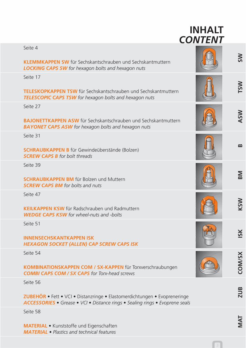
INHALTCONTENT
3
TELESKOPKAPPEN TSW für Sechskantschrauben und SechskantmutternTELESCOPIC CAPS TSW for hexagon bolts and hexagon nuts
KLEMMKAPPEN SW für Sechskantschrauben und SechskantmutternLOCKING CAPS SW for hexagon bolts and hexagon nuts
BAJONETTKAPPEN ASW für Sechskantschrauben und SechskantmutternBAYONET CAPS ASW for hexagon bolts and hexagon nuts
KEILKAPPEN KSW für Radschrauben und RadmutternWEDGE CAPS KSW for wheel-nuts and -bolts
SCHRAUBKAPPEN B für Gewindeüberstände (Bolzen)SCREW CAPS B for bolt threads
SCHRAUBKAPPEN BM für Bolzen und MutternSCREW CAPS BM for bolts and nuts
INNENSECHSKANTKAPPEN ISKHEXAGON SOCKET (ALLEN) CAP SCREW CAPS ISK
SWTS
WA
SWB
BM
KSW
ISK
CO
M/S
XZU
BM
AT
KOMBINATIONSKAPPEN COM / SX-KAPPEN für TorxverschraubungenCOMBI CAPS COM / SX CAPS for Torx-head screws
ZUBEHÖR • Fett • VCI • Distanzringe • Elastomerdichtungen • EvopreneringeACCESSORIES • Grease • VCI • Distance rings • Sealing rings • Evoprene seals
MATERIAL • Kunststoffe und EigenschaftenMATERIAL • Plastics and technical features
Seite 4
Seite 17
Seite 27
Seite 31
Seite 39
Seite 47
Seite 51
Seite 54
Seite 56
Seite 58
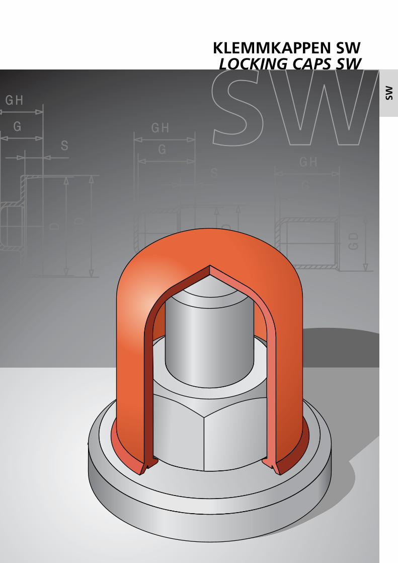
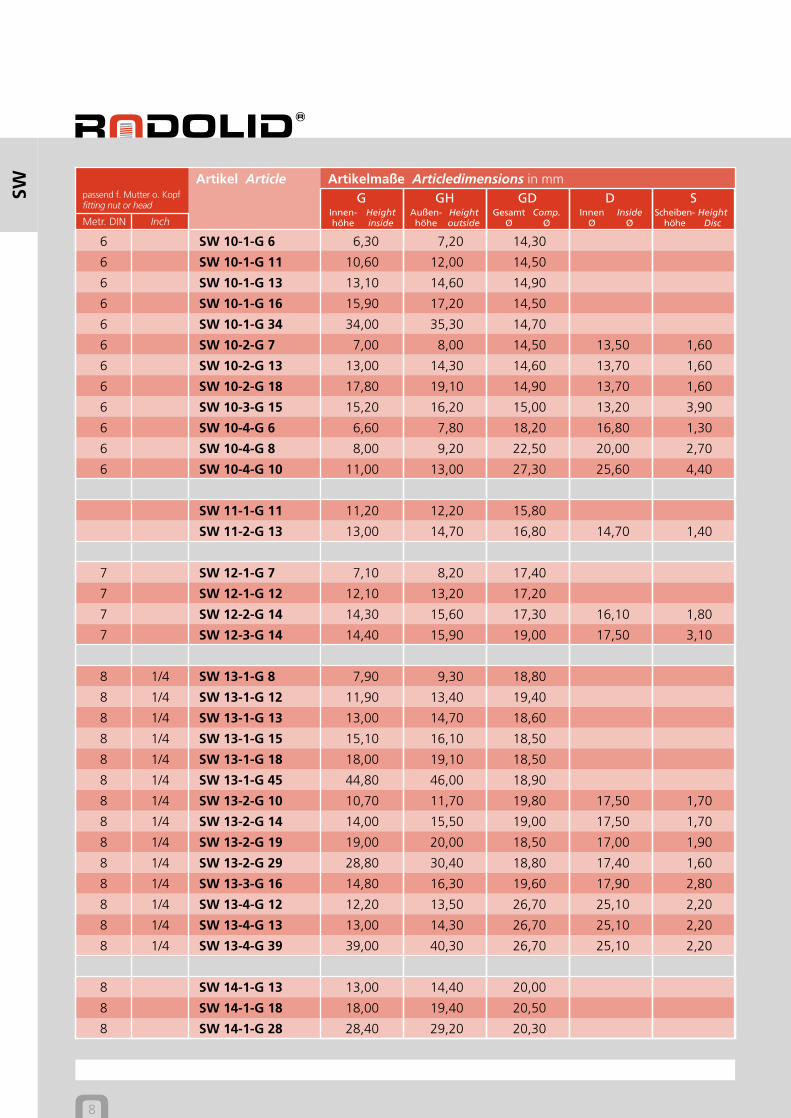
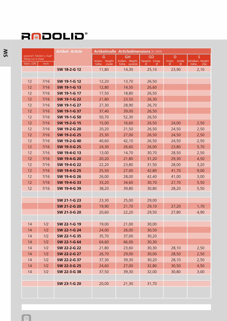
KLEMMKAPPEN SWLOCKING CAPS SW
SW
HohlkehleCircular groove
6
SW
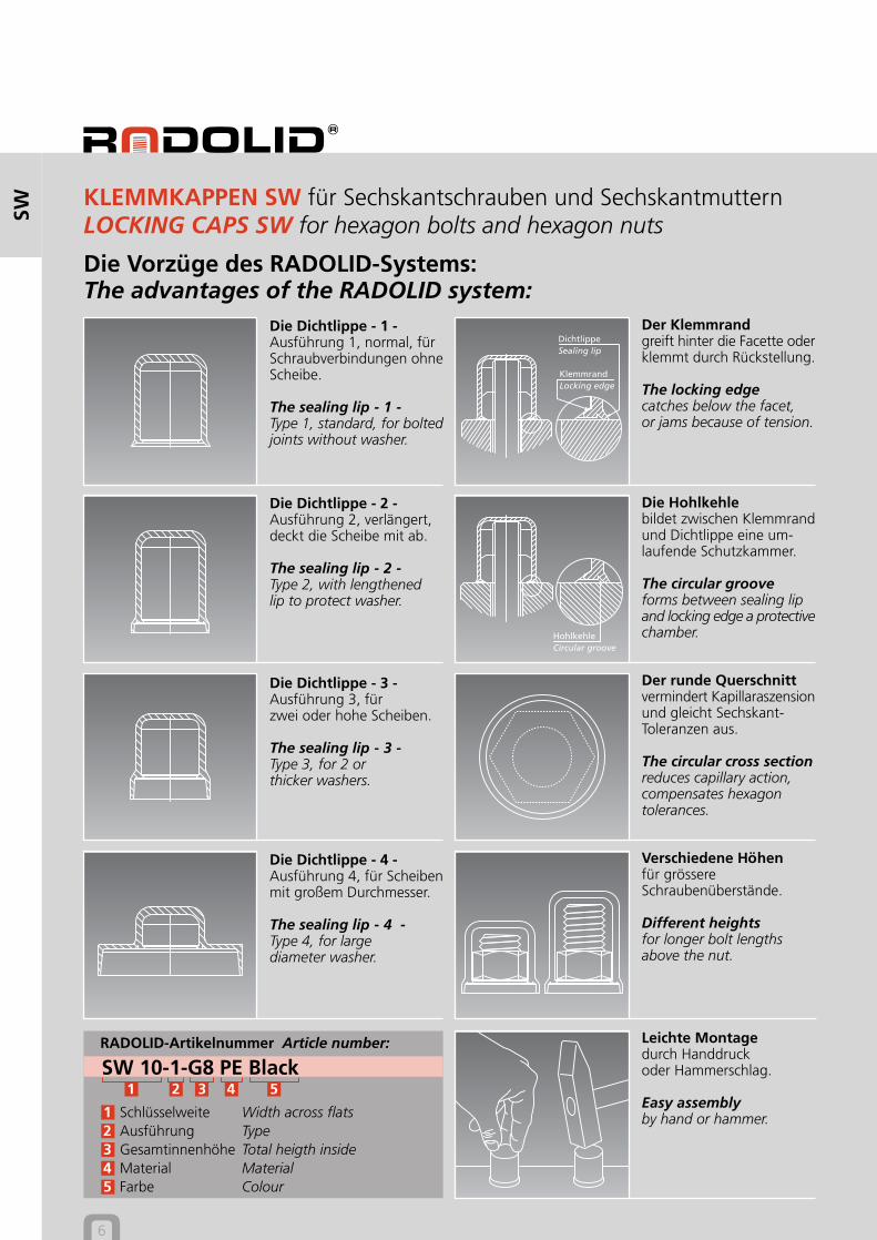
RADOLID-Artikelnummer Article number:
SW 10-1-G8 PE Black1 2 3 4 5
1 Schlüsselweite Width across flats2 Ausführung Type3 Gesamtinnenhöhe Total heigth inside4 Material Material5 Farbe Colour
Der Klemmrandgreift hinter die Facette oderklemmt durch Rückstellung.
The locking edgecatches below the facet,or jams because of tension.
Die Vorzüge des RADOLID-Systems:The advantages of the RADOLID system:
Der runde Querschnittvermindert Kapillaraszensionund gleicht Sechskant-Toleranzen aus.
The circular cross sectionreduces capillary action,compensates hexagontolerances.
Die Dichtlippe - 1 -Ausführung 1, normal, fürSchraubverbindungen ohneScheibe.
The sealing lip - 1 -Type 1, standard, for boltedjoints without washer.
Die Dichtlippe - 2 -Ausführung 2, verlängert,deckt die Scheibe mit ab.
The sealing lip - 2 -Type 2, with lengthenedlip to protect washer.
Die Dichtlippe - 3 -Ausführung 3, fürzwei oder hohe Scheiben.
The sealing lip - 3 -Type 3, for 2 orthicker washers.
Die Dichtlippe - 4 -Ausführung 4, für Scheibenmit großem Durchmesser.
The sealing lip - 4 -Type 4, for largediameter washer.
Verschiedene Höhenfür grössereSchraubenüberstände.
Different heightsfor longer bolt lengthsabove the nut.
Leichte Montagedurch Handdruckoder Hammerschlag.
Easy assemblyby hand or hammer.
Die Hohlkehlebildet zwischen Klemmrandund Dichtlippe eine um-laufende Schutzkammer.
The circular grooveforms between sealing lipand locking edge a protectivechamber.
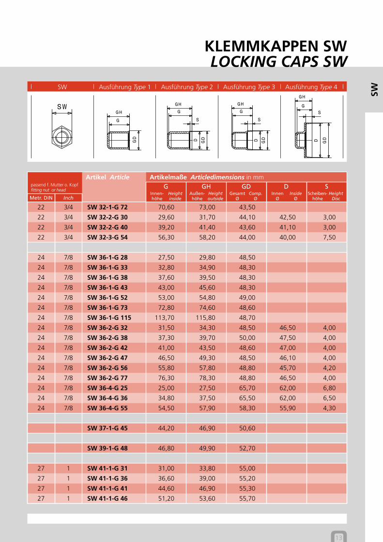
KLEMMKAPPEN SW für Sechskantschrauben und SechskantmutternLOCKING CAPS SW for hexagon bolts and hexagon nuts
KlemmrandLocking edge
DichtlippeSealing lip
Heightinside
Innen-höhe
Heightoutside
Außen-höhe
Comp.Ø
GesamtØ
InsideØ
InnenØ
HeightDisc
Scheiben-höhe
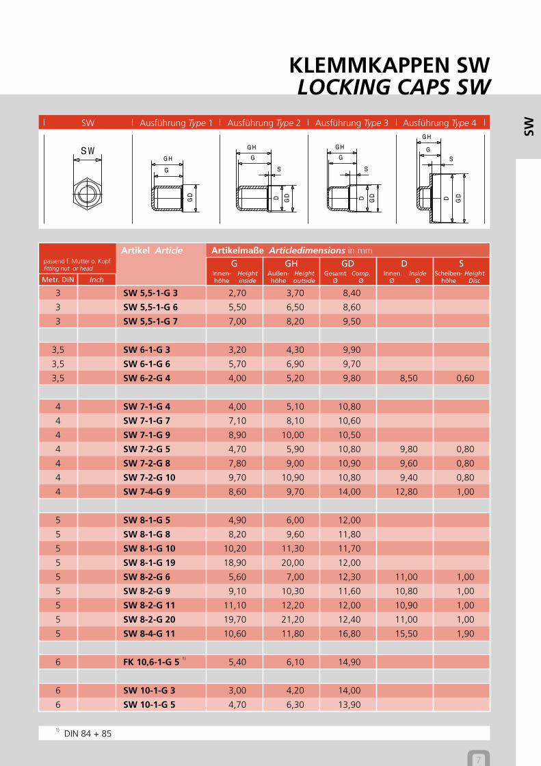
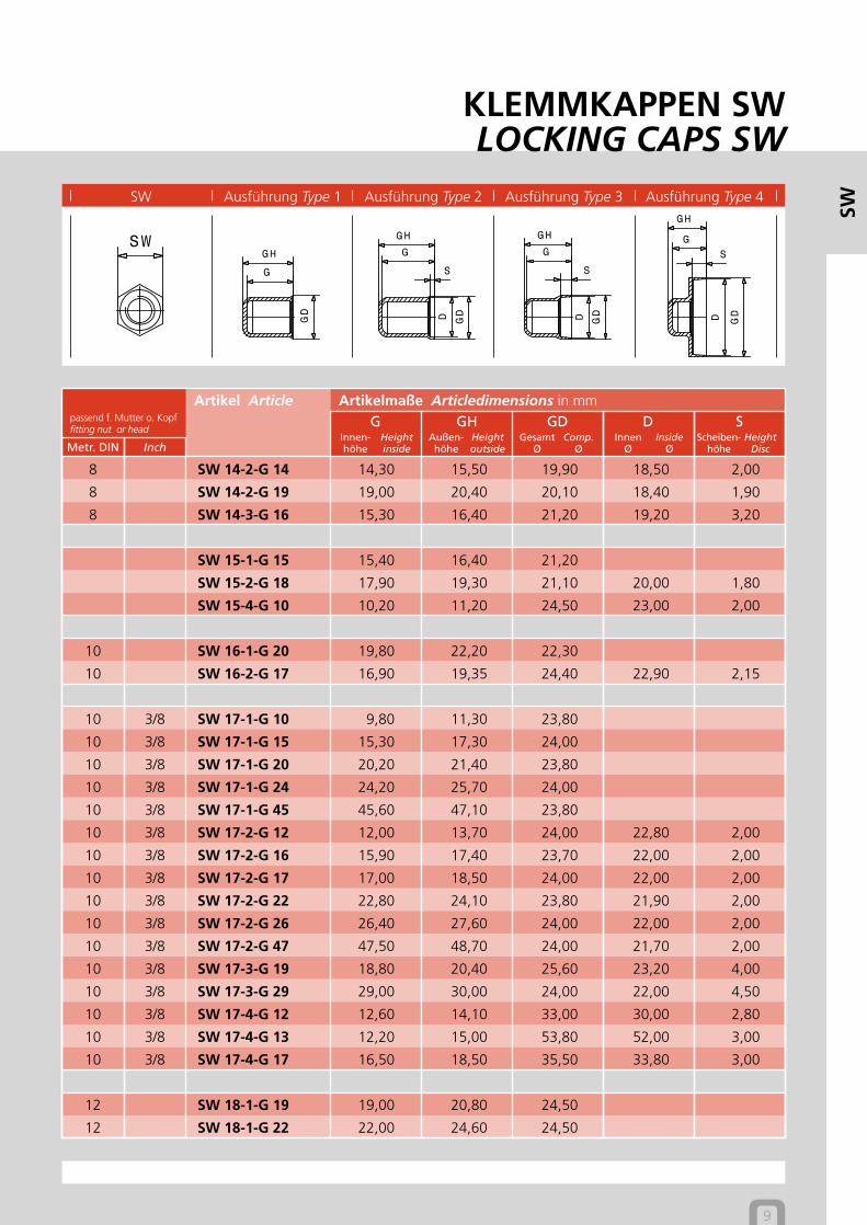
SW Ausführung Type 1 Ausführung Type 2 Ausführung Type 3 Ausführung Type 4
KLEMMKAPPEN SWLOCKING CAPS SW
7
Artikelmaße Articledimensions in mmpassend f. Mutter o. Kopffitting nut or head
Artikel ArticleG GH GD D S
Metr. DIN Inch
SW
3 SW 5,5-1-G 3 2,70 3,70 8,40
3 SW 5,5-1-G 6 5,50 6,50 8,60
3 SW 5,5-1-G 7 7,00 8,20 9,50
3,5 SW 6-1-G 3 3,20 4,30 9,90
3,5 SW 6-1-G 6 5,70 6,90 9,70
3,5 SW 6-2-G 4 4,00 5,20 9,80 8,50 0,60
4 SW 7-1-G 4 4,00 5,10 10,80
4 SW 7-1-G 7 7,10 8,10 10,60
4 SW 7-1-G 9 8,90 10,00 10,50
4 SW 7-2-G 5 4,70 5,90 10,80 9,80 0,80
4 SW 7-2-G 8 7,80 9,00 10,90 9,60 0,80
4 SW 7-2-G 10 9,70 10,90 10,80 9,40 0,80
4 SW 7-4-G 9 8,60 9,70 14,00 12,80 1,00
5 SW 8-1-G 5 4,90 6,00 12,00
5 SW 8-1-G 8 8,20 9,60 11,80
5 SW 8-1-G 10 10,20 11,30 11,70
5 SW 8-1-G 19 18,90 20,00 12,00
5 SW 8-2-G 6 5,60 7,00 12,30 11,00 1,00
5 SW 8-2-G 9 9,10 10,30 11,60 10,80 1,00
5 SW 8-2-G 11 11,10 12,20 12,00 10,90 1,00
5 SW 8-2-G 20 19,70 21,20 12,40 11,00 1,00
5 SW 8-4-G 11 10,60 11,80 16,80 15,50 1,90
6 FK 10,6-1-G 5 1)5,40 6,10 14,90
6 SW 10-1-G 3 3,00 4,20 14,00
6 SW 10-1-G 5 4,70 6,30 13,90
1) DIN 84 + 85
Heightinside
Innen-höhe
Heightoutside
Außen-höhe
Comp.Ø
GesamtØ
InsideØ
InnenØ
HeightDisc
Scheiben-höhe
8
Artikelmaße Articledimensions in mmpassend f. Mutter o. Kopffitting nut or head
Artikel ArticleG GH GD D S
Metr. DIN Inch
SW
6 SW 10-1-G 6 6,30 7,20 14,30
6 SW 10-1-G 11 10,60 12,00 14,50
6 SW 10-1-G 13 13,10 14,60 14,90
6 SW 10-1-G 16 15,90 17,20 14,50
6 SW 10-1-G 34 34,00 35,30 14,70
6 SW 10-2-G 7 7,00 8,00 14,50 13,50 1,60
6 SW 10-2-G 13 13,00 14,30 14,60 13,70 1,60
6 SW 10-2-G 18 17,80 19,10 14,90 13,70 1,60
6 SW 10-3-G 15 15,20 16,20 15,00 13,20 3,90
6 SW 10-4-G 6 6,60 7,80 18,20 16,80 1,30
6 SW 10-4-G 8 8,00 9,20 22,50 20,00 2,70
6 SW 10-4-G 10 11,00 13,00 27,30 25,60 4,40
SW 11-1-G 11 11,20 12,20 15,80
SW 11-2-G 13 13,00 14,70 16,80 14,70 1,40
7 SW 12-1-G 7 7,10 8,20 17,40
7 SW 12-1-G 12 12,10 13,20 17,20
7 SW 12-2-G 14 14,30 15,60 17,30 16,10 1,80
7 SW 12-3-G 14 14,40 15,90 19,00 17,50 3,10
8 1/4 SW 13-1-G 8 7,90 9,30 18,80
8 1/4 SW 13-1-G 12 11,90 13,40 19,40
8 1/4 SW 13-1-G 13 13,00 14,70 18,60
8 1/4 SW 13-1-G 15 15,10 16,10 18,50
8 1/4 SW 13-1-G 18 18,00 19,10 18,50
8 1/4 SW 13-1-G 45 44,80 46,00 18,90
8 1/4 SW 13-2-G 10 10,70 11,70 19,80 17,50 1,70
8 1/4 SW 13-2-G 14 14,00 15,50 19,00 17,50 1,70
8 1/4 SW 13-2-G 19 19,00 20,00 18,50 17,00 1,90
8 1/4 SW 13-2-G 29 28,80 30,40 18,80 17,40 1,60
8 1/4 SW 13-3-G 16 14,80 16,30 19,60 17,90 2,80
8 1/4 SW 13-4-G 12 12,20 13,50 26,70 25,10 2,20
8 1/4 SW 13-4-G 13 13,00 14,30 26,70 25,10 2,20
8 1/4 SW 13-4-G 39 39,00 40,30 26,70 25,10 2,20
8 SW 14-1-G 13 13,00 14,40 20,00
8 SW 14-1-G 18 18,00 19,40 20,50
8 SW 14-1-G 28 28,40 29,20 20,30
Heightinside
Innen-höhe
Heightoutside
Außen-höhe
Comp.Ø
GesamtØ
InsideØ
InnenØ
HeightDisc
Scheiben-höhe
SW Ausführung Type 1 Ausführung Type 2 Ausführung Type 3 Ausführung Type 4
KLEMMKAPPEN SWLOCKING CAPS SW
9
Artikelmaße Articledimensions in mmpassend f. Mutter o. Kopffitting nut or head
Artikel ArticleG GH GD D S
Metr. DIN Inch
SW
8 SW 14-2-G 14 14,30 15,50 19,90 18,50 2,00
8 SW 14-2-G 19 19,00 20,40 20,10 18,40 1,90
8 SW 14-3-G 16 15,30 16,40 21,20 19,20 3,20
SW 15-1-G 15 15,40 16,40 21,20
SW 15-2-G 18 17,90 19,30 21,10 20,00 1,80
SW 15-4-G 10 10,20 11,20 24,50 23,00 2,00
10 SW 16-1-G 20 19,80 22,20 22,30
10 SW 16-2-G 17 16,90 19,35 24,40 22,90 2,15
10 3/8 SW 17-1-G 10 9,80 11,30 23,80
10 3/8 SW 17-1-G 15 15,30 17,30 24,00
10 3/8 SW 17-1-G 20 20,20 21,40 23,80
10 3/8 SW 17-1-G 24 24,20 25,70 24,00
10 3/8 SW 17-1-G 45 45,60 47,10 23,80
10 3/8 SW 17-2-G 12 12,00 13,70 24,00 22,80 2,00
10 3/8 SW 17-2-G 16 15,90 17,40 23,70 22,00 2,00
10 3/8 SW 17-2-G 17 17,00 18,50 24,00 22,00 2,00
10 3/8 SW 17-2-G 22 22,80 24,10 23,80 21,90 2,00
10 3/8 SW 17-2-G 26 26,40 27,60 24,00 22,00 2,00
10 3/8 SW 17-2-G 47 47,50 48,70 24,00 21,70 2,00
10 3/8 SW 17-3-G 19 18,80 20,40 25,60 23,20 4,00
10 3/8 SW 17-3-G 29 29,00 30,00 24,00 22,00 4,50
10 3/8 SW 17-4-G 12 12,60 14,10 33,00 30,00 2,80
10 3/8 SW 17-4-G 13 12,20 15,00 53,80 52,00 3,00
10 3/8 SW 17-4-G 17 16,50 18,50 35,50 33,80 3,00
12 SW 18-1-G 19 19,00 20,80 24,50
12 SW 18-1-G 22 22,00 24,60 24,50
Heightinside
Innen-höhe
Heightoutside
Außen-höhe
Comp.Ø
GesamtØ
InsideØ
InnenØ
HeightDisc
Scheiben-höhe
10
Artikelmaße Articledimensions in mmpassend f. Mutter o. Kopffitting nut or head
Artikel ArticleG GH GD D S
Metr. DIN Inch
SW
SW 18-2-G 12 11,80 14,30 25,10 23,90 2,10
12 7/16 SW 19-1-G 12 12,20 13,70 26,50
12 7/16 SW 19-1-G 13 12,80 14,50 26,60
12 7/16 SW 19-1-G 17 17,50 18,80 26,50
12 7/16 SW 19-1-G 22 21,80 23,50 26,30
12 7/16 SW 19-1-G 27 27,30 28,90 26,70
12 7/16 SW 19-1-G 37 37,40 39,00 26,50
12 7/16 SW 19-1-G 50 50,70 52,30 26,50
12 7/16 SW 19-2-G 15 15,00 16,60 26,50 24,00 2,50
12 7/16 SW 19-2-G 20 20,20 21,50 26,50 24,50 2,50
12 7/16 SW 19-2-G 25 25,30 27,00 26,50 24,50 2,50
12 7/16 SW 19-2-G 40 40,60 42,10 26,50 24,50 2,50
12 7/16 SW 19-3-G 25 24,30 26,60 26,00 23,80 5,70
12 7/16 SW 19-4-G 13 13,00 14,70 30,70 28,50 2,50
12 7/16 SW 19-4-G 20 20,20 21,80 31,20 29,30 4,50
12 7/16 SW 19-4-G 22 22,20 23,80 31,50 28,00 3,20
12 7/16 SW 19-4-G 25 25,50 27,00 42,80 41,70 9,00
12 7/16 SW 19-4-G 26 26,00 28,00 42,40 41,00 3,00
12 7/16 SW 19-4-G 33 33,20 34,60 30,70 27,70 5,50
12 7/16 SW 19-4-G 39 38,20 39,80 30,80 28,20 5,50
SW 21-1-G 23 23,30 25,00 29,00
SW 21-2-G 20 19,90 21,70 29,10 27,20 1,70
SW 21-3-G 20 20,60 22,20 29,50 27,80 4,90
14 1/2 SW 22-1-G 19 19,00 21,00 30,00
14 1/2 SW 22-1-G 24 24,00 26,00 30,50
14 1/2 SW 22-1-G 35 35,70 37,00 30,20
14 1/2 SW 22-1-G 64 64,60 66,00 30,30
14 1/2 SW 22-2-G 22 21,80 23,60 30,30 28,10 2,50
14 1/2 SW 22-2-G 27 26,70 29,00 30,00 28,50 2,50
14 1/2 SW 22-2-G 37 37,30 39,30 30,20 28,10 2,50
14 1/2 SW 22-3-G 25 24,60 27,00 32,80 30,50 4,50
14 1/2 SW 22-3-G 38 37,50 39,30 32,00 30,80 3,00
SW 23-1-G 20 20,00 21,30 31,70
Heightinside
Innen-höhe
Heightoutside
Außen-höhe
Comp.Ø
GesamtØ
InsideØ
InnenØ
HeightDisc
Scheiben-höhe
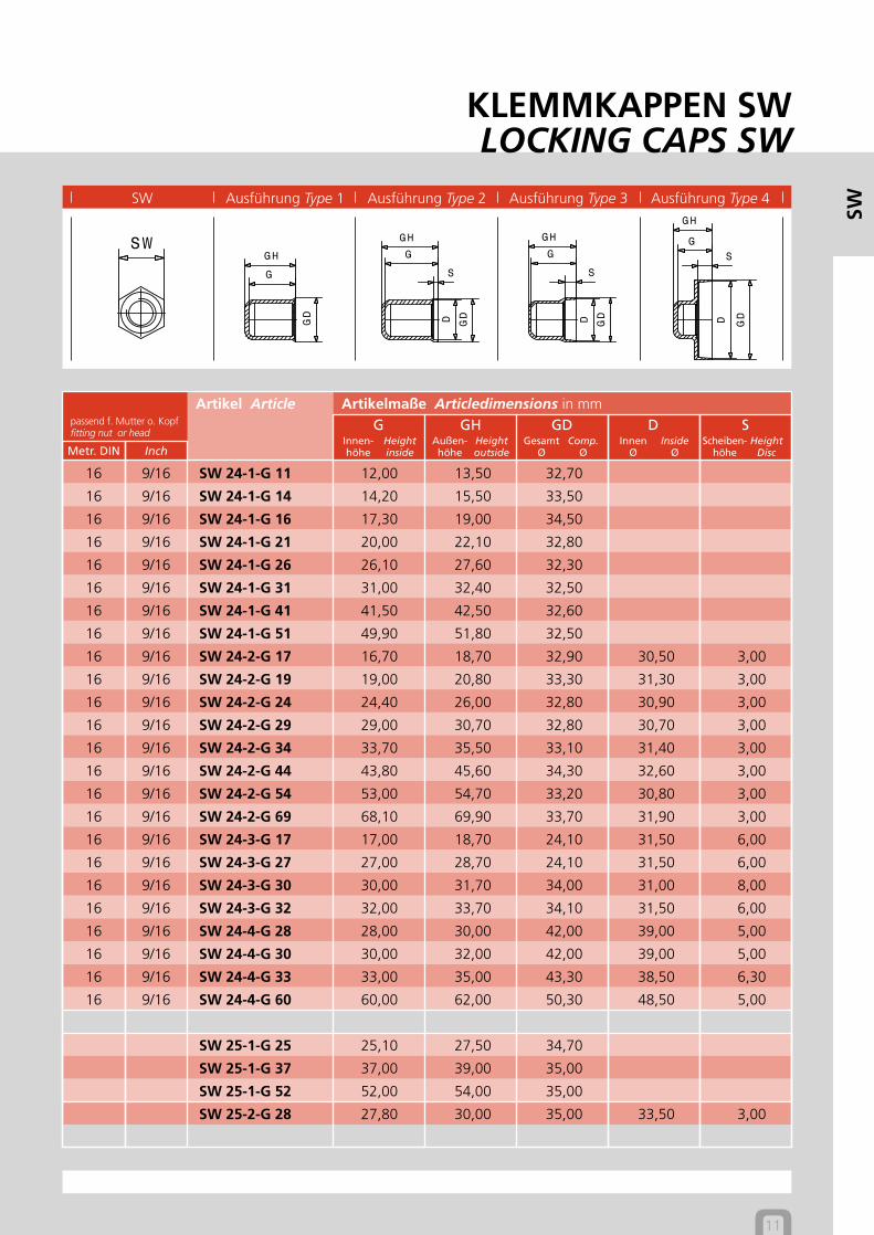
SW Ausführung Type 1 Ausführung Type 2 Ausführung Type 3 Ausführung Type 4
KLEMMKAPPEN SWLOCKING CAPS SW
11
Artikelmaße Articledimensions in mmpassend f. Mutter o. Kopffitting nut or head
Artikel ArticleG GH GD D S
Metr. DIN Inch
SW
16 9/16 SW 24-1-G 11 12,00 13,50 32,70
16 9/16 SW 24-1-G 14 14,20 15,50 33,50
16 9/16 SW 24-1-G 16 17,30 19,00 34,50
16 9/16 SW 24-1-G 21 20,00 22,10 32,80
16 9/16 SW 24-1-G 26 26,10 27,60 32,30
16 9/16 SW 24-1-G 31 31,00 32,40 32,50
16 9/16 SW 24-1-G 41 41,50 42,50 32,60
16 9/16 SW 24-1-G 51 49,90 51,80 32,50
16 9/16 SW 24-2-G 17 16,70 18,70 32,90 30,50 3,00
16 9/16 SW 24-2-G 19 19,00 20,80 33,30 31,30 3,00
16 9/16 SW 24-2-G 24 24,40 26,00 32,80 30,90 3,00
16 9/16 SW 24-2-G 29 29,00 30,70 32,80 30,70 3,00
16 9/16 SW 24-2-G 34 33,70 35,50 33,10 31,40 3,00
16 9/16 SW 24-2-G 44 43,80 45,60 34,30 32,60 3,00
16 9/16 SW 24-2-G 54 53,00 54,70 33,20 30,80 3,00
16 9/16 SW 24-2-G 69 68,10 69,90 33,70 31,90 3,00
16 9/16 SW 24-3-G 17 17,00 18,70 24,10 31,50 6,00
16 9/16 SW 24-3-G 27 27,00 28,70 24,10 31,50 6,00
16 9/16 SW 24-3-G 30 30,00 31,70 34,00 31,00 8,00
16 9/16 SW 24-3-G 32 32,00 33,70 34,10 31,50 6,00
16 9/16 SW 24-4-G 28 28,00 30,00 42,00 39,00 5,00
16 9/16 SW 24-4-G 30 30,00 32,00 42,00 39,00 5,00
16 9/16 SW 24-4-G 33 33,00 35,00 43,30 38,50 6,30
16 9/16 SW 24-4-G 60 60,00 62,00 50,30 48,50 5,00
SW 25-1-G 25 25,10 27,50 34,70
SW 25-1-G 37 37,00 39,00 35,00
SW 25-1-G 52 52,00 54,00 35,00
SW 25-2-G 28 27,80 30,00 35,00 33,50 3,00
Heightinside
Innen-höhe
Heightoutside
Außen-höhe
Comp.Ø
GesamtØ
InsideØ
InnenØ
HeightDisc
Scheiben-höhe
12
Artikelmaße Articledimensions in mmpassend f. Mutter o. Kopffitting nut or head
Artikel ArticleG GH GD D S
Metr. DIN Inch
SW
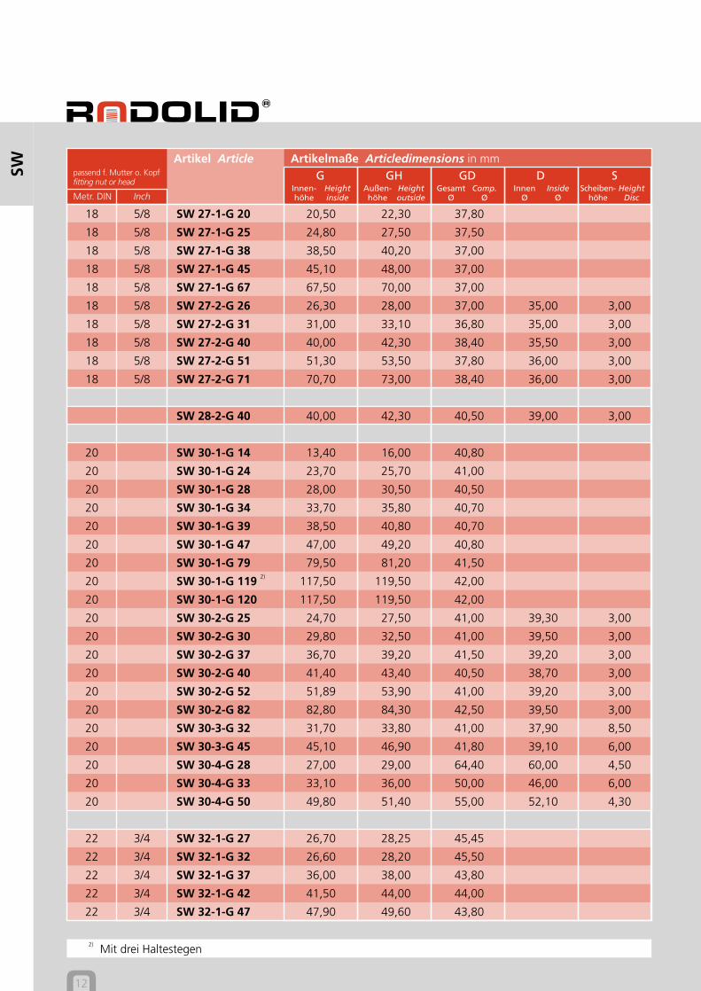
18 5/8 SW 27-1-G 20 20,50 22,30 37,80
18 5/8 SW 27-1-G 25 24,80 27,50 37,50
18 5/8 SW 27-1-G 38 38,50 40,20 37,00
18 5/8 SW 27-1-G 45 45,10 48,00 37,00
18 5/8 SW 27-1-G 67 67,50 70,00 37,00
18 5/8 SW 27-2-G 26 26,30 28,00 37,00 35,00 3,00
18 5/8 SW 27-2-G 31 31,00 33,10 36,80 35,00 3,00
18 5/8 SW 27-2-G 40 40,00 42,30 38,40 35,50 3,00
18 5/8 SW 27-2-G 51 51,30 53,50 37,80 36,00 3,00
18 5/8 SW 27-2-G 71 70,70 73,00 38,40 36,00 3,00
SW 28-2-G 40 40,00 42,30 40,50 39,00 3,00
20 SW 30-1-G 14 13,40 16,00 40,80
20 SW 30-1-G 24 23,70 25,70 41,00
20 SW 30-1-G 28 28,00 30,50 40,50
20 SW 30-1-G 34 33,70 35,80 40,70
20 SW 30-1-G 39 38,50 40,80 40,70
20 SW 30-1-G 47 47,00 49,20 40,80
20 SW 30-1-G 79 79,50 81,20 41,50
20 SW 30-1-G 119 2)117,50 119,50 42,00
20 SW 30-1-G 120 117,50 119,50 42,00
20 SW 30-2-G 25 24,70 27,50 41,00 39,30 3,00
20 SW 30-2-G 30 29,80 32,50 41,00 39,50 3,00
20 SW 30-2-G 37 36,70 39,20 41,50 39,20 3,00
20 SW 30-2-G 40 41,40 43,40 40,50 38,70 3,00
20 SW 30-2-G 52 51,89 53,90 41,00 39,20 3,00
20 SW 30-2-G 82 82,80 84,30 42,50 39,50 3,00
20 SW 30-3-G 32 31,70 33,80 41,00 37,90 8,50
20 SW 30-3-G 45 45,10 46,90 41,80 39,10 6,00
20 SW 30-4-G 28 27,00 29,00 64,40 60,00 4,50
20 SW 30-4-G 33 33,10 36,00 50,00 46,00 6,00
20 SW 30-4-G 50 49,80 51,40 55,00 52,10 4,30
22 3/4 SW 32-1-G 27 26,70 28,25 45,45
22 3/4 SW 32-1-G 32 26,60 28,20 45,50
22 3/4 SW 32-1-G 37 36,00 38,00 43,80
22 3/4 SW 32-1-G 42 41,50 44,00 44,00
22 3/4 SW 32-1-G 47 47,90 49,60 43,80
2) Mit drei Haltestegen
Heightinside
Innen-höhe
Heightoutside
Außen-höhe
Comp.Ø
GesamtØ
InsideØ
InnenØ
HeightDisc
Scheiben-höhe
SW Ausführung Type 1 Ausführung Type 2 Ausführung Type 3 Ausführung Type 4
KLEMMKAPPEN SWLOCKING CAPS SW
13
Artikelmaße Articledimensions in mmpassend f. Mutter o. Kopffitting nut or head
Artikel ArticleG GH GD D S
Metr. DIN Inch
SW
22 3/4 SW 32-1-G 72 70,60 73,00 43,50
22 3/4 SW 32-2-G 30 29,60 31,70 44,10 42,50 3,00
22 3/4 SW 32-2-G 40 39,20 41,40 43,60 41,10 3,00
22 3/4 SW 32-3-G 54 56,30 58,20 44,00 40,00 7,50
24 7/8 SW 36-1-G 28 27,50 29,80 48,50
24 7/8 SW 36-1-G 33 32,80 34,90 48,30
24 7/8 SW 36-1-G 38 37,60 39,50 48,30
24 7/8 SW 36-1-G 43 43,00 45,60 48,30
24 7/8 SW 36-1-G 52 53,00 54,80 49,00
24 7/8 SW 36-1-G 73 72,80 74,60 48,60
24 7/8 SW 36-1-G 115 113,70 115,80 48,70
24 7/8 SW 36-2-G 32 31,50 34,30 48,50 46,50 4,00
24 7/8 SW 36-2-G 38 37,30 39,70 50,00 47,50 4,00
24 7/8 SW 36-2-G 42 41,00 43,50 48,60 47,00 4,00
24 7/8 SW 36-2-G 47 46,50 49,30 48,50 46,10 4,00
24 7/8 SW 36-2-G 56 55,80 57,80 48,80 45,70 4,20
24 7/8 SW 36-2-G 77 76,30 78,30 48,80 46,50 4,00
24 7/8 SW 36-4-G 25 25,00 27,50 65,70 62,00 6,80
24 7/8 SW 36-4-G 36 34,80 37,50 65,50 62,00 6,50
24 7/8 SW 36-4-G 55 54,50 57,90 58,30 55,90 4,30
SW 37-1-G 45 44,20 46,90 50,60
SW 39-1-G 48 46,80 49,90 52,70
27 1 SW 41-1-G 31 31,00 33,80 55,00
27 1 SW 41-1-G 36 36,60 39,00 55,20
27 1 SW 41-1-G 41 44,60 46,90 55,30
27 1 SW 41-1-G 46 51,20 53,60 55,70
Heightinside
Innen-höhe
Heightoutside
Außen-höhe
Comp.Ø
GesamtØ
InsideØ
InnenØ
HeightDisc
Scheiben-höhe
14
Artikelmaße Articledimensions in mmpassend f. Mutter o. Kopffitting nut or head
Artikel ArticleG GH GD D S
Metr. DIN Inch
SW
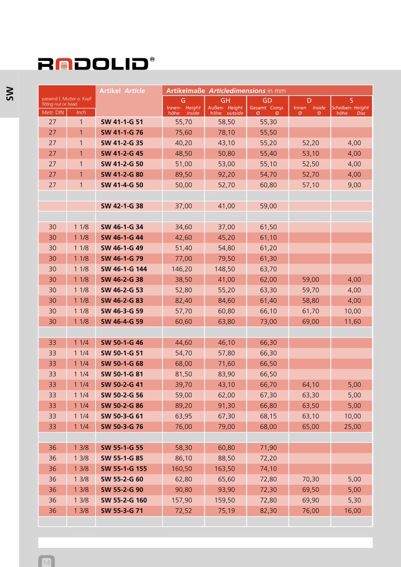
27 1 SW 41-1-G 51 55,70 58,50 55,30
27 1 SW 41-1-G 76 75,60 78,10 55,50
27 1 SW 41-2-G 35 40,20 43,10 55,20 52,20 4,00
27 1 SW 41-2-G 45 48,50 50,80 55,40 53,10 4,00
27 1 SW 41-2-G 50 51,00 53,00 55,10 52,50 4,00
27 1 SW 41-2-G 80 89,50 92,20 54,70 52,70 4,00
27 1 SW 41-4-G 50 50,00 52,70 60,80 57,10 9,00
SW 42-1-G 38 37,00 41,00 59,00
30 1 1/8 SW 46-1-G 34 34,60 37,00 61,50
30 1 1/8 SW 46-1-G 44 42,60 45,20 61,10
30 1 1/8 SW 46-1-G 49 51,40 54,80 61,20
30 1 1/8 SW 46-1-G 79 77,00 79,50 61,30
30 1 1/8 SW 46-1-G 144 146,20 148,50 63,70
30 1 1/8 SW 46-2-G 38 38,50 41,00 62,00 59,00 4,00
30 1 1/8 SW 46-2-G 53 52,80 55,20 63,30 59,70 4,00
30 1 1/8 SW 46-2-G 83 82,40 84,60 61,40 58,80 4,00
30 1 1/8 SW 46-3-G 59 57,70 60,80 66,10 61,70 10,00
30 1 1/8 SW 46-4-G 59 60,60 63,80 73,00 69,00 11,60
33 1 1/4 SW 50-1-G 46 44,60 46,10 66,30
33 1 1/4 SW 50-1-G 51 54,70 57,80 66,30
33 1 1/4 SW 50-1-G 68 68,00 71,60 66,50
33 1 1/4 SW 50-1-G 81 81,50 83,90 66,50
33 1 1/4 SW 50-2-G 41 39,70 43,10 66,70 64,10 5,00
33 1 1/4 SW 50-2-G 56 59,00 62,00 67,30 63,30 5,00
33 1 1/4 SW 50-2-G 86 89,20 91,30 66,80 63,50 5,00
33 1 1/4 SW 50-3-G 61 63,95 67,30 68,15 63,10 10,00
33 1 1/4 SW 50-3-G 76 76,00 79,00 68,00 65,00 25,00
36 1 3/8 SW 55-1-G 55 58,30 60,80 71,90
36 1 3/8 SW 55-1-G 85 86,10 88,50 72,20
36 1 3/8 SW 55-1-G 155 160,50 163,50 74,10
36 1 3/8 SW 55-2-G 60 62,80 65,60 72,80 70,30 5,00
36 1 3/8 SW 55-2-G 90 90,80 93,90 72,30 69,50 5,00
36 1 3/8 SW 55-2-G 160 157,90 159,50 72,80 69,90 5,30
36 1 3/8 SW 55-3-G 71 72,52 75,19 82,30 76,00 16,00
Heightinside
Innen-höhe
Heightoutside
Außen-höhe
Comp.Ø
GesamtØ
InsideØ
InnenØ
HeightDisc
Scheiben-höhe
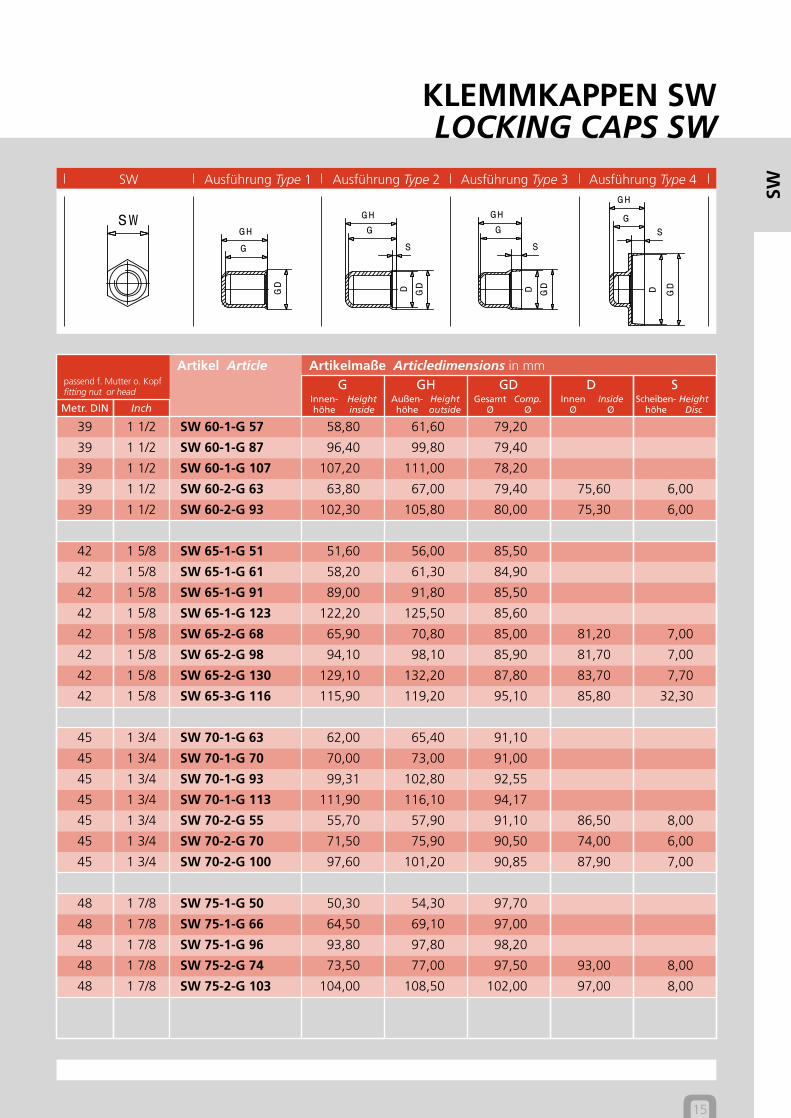
SW Ausführung Type 1 Ausführung Type 2 Ausführung Type 3 Ausführung Type 4
KLEMMKAPPEN SWLOCKING CAPS SW
15
Artikelmaße Articledimensions in mmpassend f. Mutter o. Kopffitting nut or head
Artikel ArticleG GH GD D S
Metr. DIN Inch
SW
39 1 1/2 SW 60-1-G 57 58,80 61,60 79,20
39 1 1/2 SW 60-1-G 87 96,40 99,80 79,40
39 1 1/2 SW 60-1-G 107 107,20 111,00 78,20
39 1 1/2 SW 60-2-G 63 63,80 67,00 79,40 75,60 6,00
39 1 1/2 SW 60-2-G 93 102,30 105,80 80,00 75,30 6,00
42 1 5/8 SW 65-1-G 51 51,60 56,00 85,50
42 1 5/8 SW 65-1-G 61 58,20 61,30 84,90
42 1 5/8 SW 65-1-G 91 89,00 91,80 85,50
42 1 5/8 SW 65-1-G 123 122,20 125,50 85,60
42 1 5/8 SW 65-2-G 68 65,90 70,80 85,00 81,20 7,00
42 1 5/8 SW 65-2-G 98 94,10 98,10 85,90 81,70 7,00
42 1 5/8 SW 65-2-G 130 129,10 132,20 87,80 83,70 7,70
42 1 5/8 SW 65-3-G 116 115,90 119,20 95,10 85,80 32,30
45 1 3/4 SW 70-1-G 63 62,00 65,40 91,10
45 1 3/4 SW 70-1-G 70 70,00 73,00 91,00
45 1 3/4 SW 70-1-G 93 99,31 102,80 92,55
45 1 3/4 SW 70-1-G 113 111,90 116,10 94,17
45 1 3/4 SW 70-2-G 55 55,70 57,90 91,10 86,50 8,00
45 1 3/4 SW 70-2-G 70 71,50 75,90 90,50 74,00 6,00
45 1 3/4 SW 70-2-G 100 97,60 101,20 90,85 87,90 7,00
48 1 7/8 SW 75-1-G 50 50,30 54,30 97,70
48 1 7/8 SW 75-1-G 66 64,50 69,10 97,00
48 1 7/8 SW 75-1-G 96 93,80 97,80 98,20
48 1 7/8 SW 75-2-G 74 73,50 77,00 97,50 93,00 8,00
48 1 7/8 SW 75-2-G 103 104,00 108,50 102,00 97,00 8,00
Heightinside
Innen-höhe
Heightoutside
Außen-höhe
Comp.Ø
GesamtØ
InsideØ
InnenØ
HeightDisc
Scheiben-höhe
16
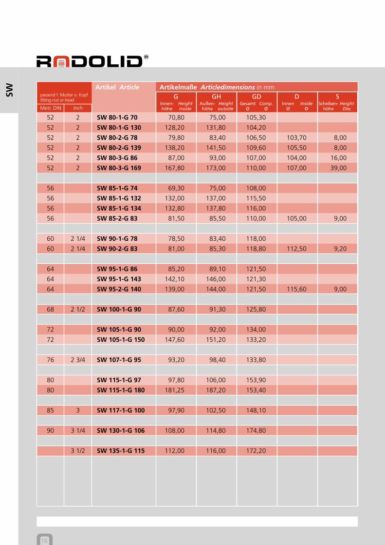
Artikelmaße Articledimensions in mmpassend f. Mutter o. Kopffitting nut or head
Artikel ArticleG GH GD D S
Metr. DIN Inch
SW
52 2 SW 80-1-G 70 70,80 75,00 105,30
52 2 SW 80-1-G 130 128,20 131,80 104,20
52 2 SW 80-2-G 78 79,80 83,40 106,50 103,70 8,00
52 2 SW 80-2-G 139 138,20 141,50 109,60 105,50 8,00
52 2 SW 80-3-G 86 87,00 93,00 107,00 104,00 16,00
52 2 SW 80-3-G 169 167,80 173,00 110,00 107,00 39,00
56 SW 85-1-G 74 69,30 75,00 108,00
56 SW 85-1-G 132 132,00 137,00 115,50
56 SW 85-1-G 134 132,80 137,80 116,00
56 SW 85-2-G 83 81,50 85,50 110,00 105,00 9,00
60 2 1/4 SW 90-1-G 78 78,50 83,40 118,00
60 2 1/4 SW 90-2-G 83 81,00 85,30 118,80 112,50 9,20
64 SW 95-1-G 86 85,20 89,10 121,50
64 SW 95-1-G 143 142,10 146,00 121,30
64 SW 95-2-G 140 139,00 144,00 121,50 115,60 9,00
68 2 1/2 SW 100-1-G 90 87,60 91,30 125,80
72 SW 105-1-G 90 90,00 92,00 134,00
72 SW 105-1-G 150 147,60 151,20 133,20
76 2 3/4 SW 107-1-G 95 93,20 98,40 133,80
80 SW 115-1-G 97 97,80 106,00 153,90
80 SW 115-1-G 180 181,25 187,20 153,40
85 3 SW 117-1-G 100 97,90 102,50 148,10
90 3 1/4 SW 130-1-G 106 108,00 114,80 174,80
3 1/2 SW 135-1-G 115 112,00 116,00 172,20
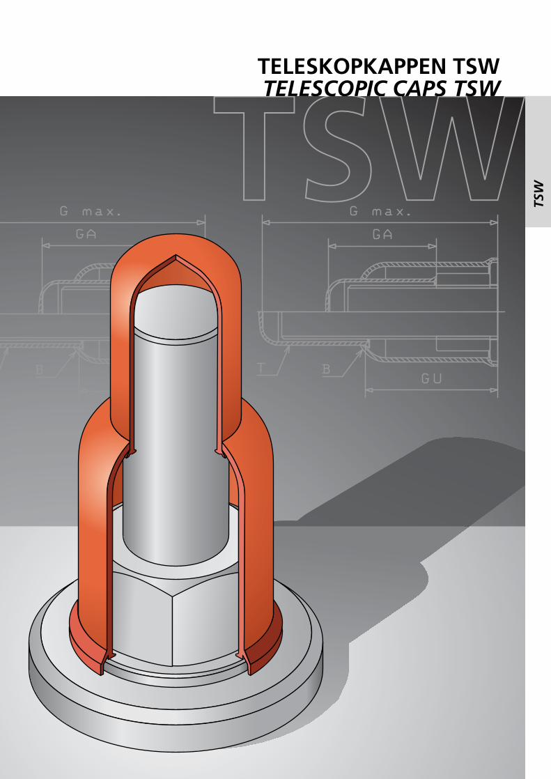
TELESKOPKAPPEN TSWTELESCOPIC CAPS TSW
TSW
TSW
Der Klemmrandgreift hinter die Facette oderklemmt durch Rückstellung.
The locking edgecatches below the facet,or jams because of tension.
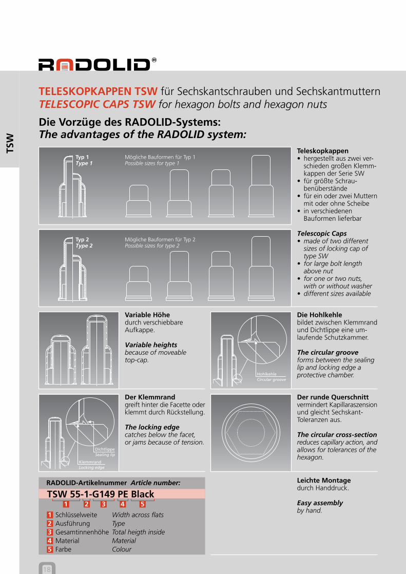
Die Vorzüge des RADOLID-Systems:The advantages of the RADOLID system:
Der runde Querschnittvermindert Kapillaraszensionund gleicht Sechskant-Toleranzen aus.
The circular cross-sectionreduces capillary action, andallows for tolerances of thehexagon.
Teleskopkappen• hergestellt aus zwei ver-
schieden großen Klemm-kappen der Serie SW
• für größte Schrau-benüberstände
• für ein oder zwei Mutternmit oder ohne Scheibe
• in verschiedenenBauformen lieferbar
Telescopic Caps• made of two different
sizes of locking cap oftype SW
• for large bolt lengthabove nut
• for one or two nuts,with or without washer
• different sizes available
Leichte Montagedurch Handdruck.
Easy assemblyby hand.
Variable Höhedurch verschiebbareAufkappe.
Variable heightsbecause of moveabletop-cap.
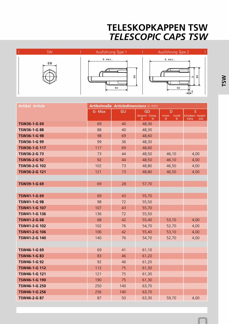
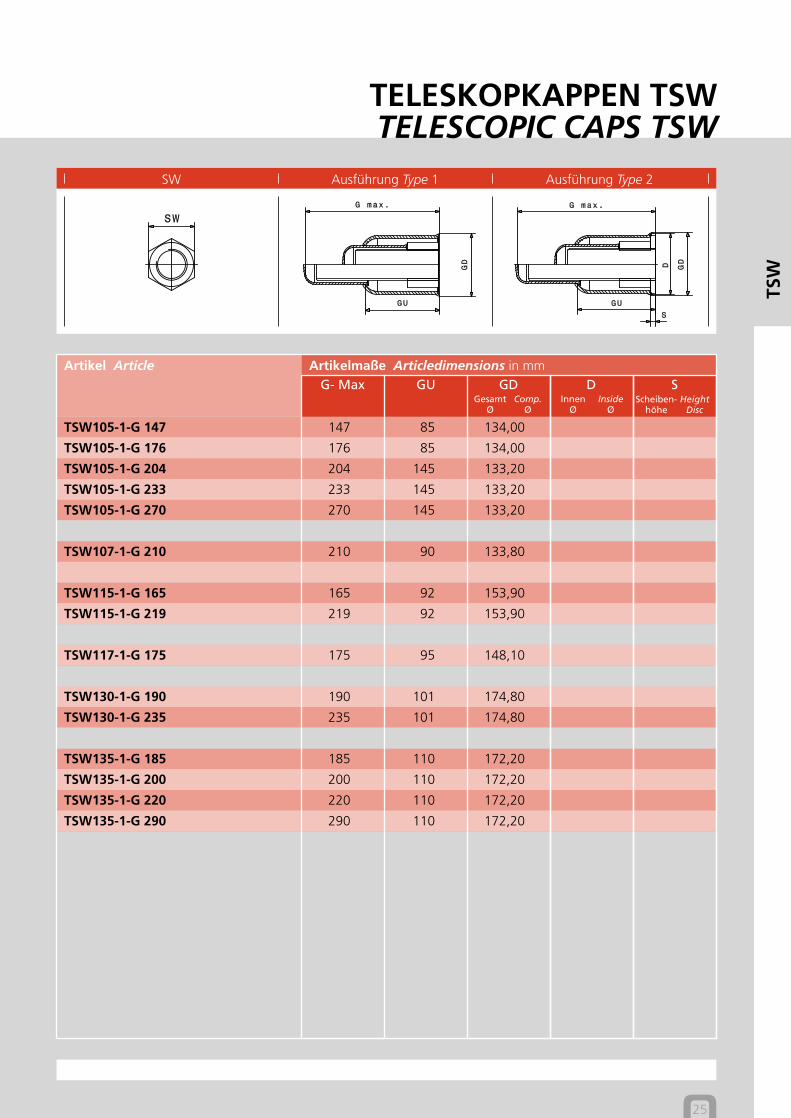
TELESKOPKAPPEN TSW für Sechskantschrauben und SechskantmutternTELESCOPIC CAPS TSW for hexagon bolts and hexagon nuts
Die Hohlkehlebildet zwischen Klemmrandund Dichtlippe eine um-laufende Schutzkammer.
The circular grooveforms between the sealinglip and locking edge aprotective chamber.
Typ 1 Mögliche Bauformen für Typ 1Type 1 Possible sizes for type 1
Typ 2 Mögliche Bauformen für Typ 2Type 2 Possible sizes for type 2
DichtlippeSealing lip
18
TSW
RADOLID-Artikelnummer Article number:
TSW 55-1-G149 PE Black1 2 3 4 5
1 Schlüsselweite Width across flats2 Ausführung Type3 Gesamtinnenhöhe Total heigth inside4 Material Material5 Farbe Colour
HohlkehleCircular groove
KlemmrandLocking edge
Comp.Ø
GesamtØ
InsideØ
InnenØ
SW Ausführung Type 1 Ausführung Type 2
TELESKOPKAPPEN TSWTELESCOPIC CAPS TSW
HeightDisc
Scheiben-höhe
19
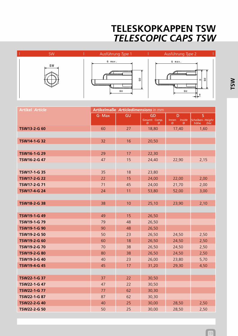
Artikelmaße Articledimensions in mmArtikel ArticleG- Max GU GD D S
TSW
TSW13-2-G 60 60 27 18,80 17,40 1,60
TSW14-1-G 32 32 16 20,50
TSW16-1-G 29 29 17 22,30
TSW16-2-G 47 47 15 24,40 22,90 2,15
TSW17-1-G 35 35 18 23,80
TSW17-2-G 22 22 15 24,00 22,00 2,00
TSW17-2-G 71 71 45 24,00 21,70 2,00
TSW17-4-G 24 24 11 53,80 52,00 3,00
TSW18-2-G 38 38 10 25,10 23,90 2,10
TSW19-1-G 49 49 15 26,50
TSW19-1-G 79 79 48 26,50
TSW19-1-G 90 90 48 26,50
TSW19-2-G 50 50 23 26,50 24,50 2,50
TSW19-2-G 60 60 18 26,50 24,50 2,50
TSW19-2-G 70 70 38 26,50 24,50 2,50
TSW19-2-G 80 80 38 26,50 24,50 2,50
TSW19-3-G 40 40 23 26,00 23,80 5,70
TSW19-4-G 45 45 17 31,20 29,30 4,50
TSW22-1-G 37 37 22 30,50
TSW22-1-G 47 47 22 30,50
TSW22-1-G 77 77 62 30,30
TSW22-1-G 87 87 62 30,30
TSW22-2-G 40 40 25 30,00 28,50 2,50
TSW22-2-G 50 50 25 30,00 28,50 2,50
Comp.Ø
GesamtØ
InsideØ
InnenØ
HeightDisc
Scheiben-höhe
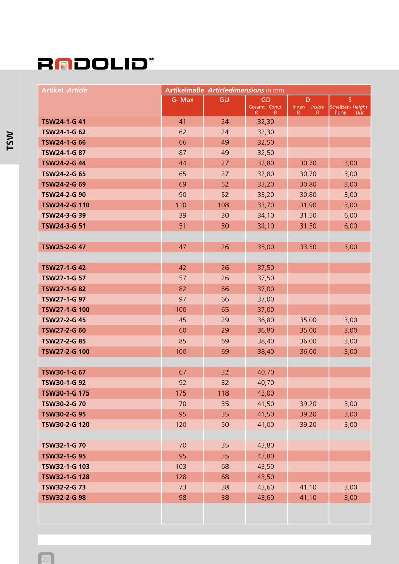
20
Artikelmaße Articledimensions in mmArtikel ArticleG- Max GU GD D S
TSW
TSW24-1-G 41 41 24 32,30
TSW24-1-G 62 62 24 32,30
TSW24-1-G 66 66 49 32,50
TSW24-1-G 87 87 49 32,50
TSW24-2-G 44 44 27 32,80 30,70 3,00
TSW24-2-G 65 65 27 32,80 30,70 3,00
TSW24-2-G 69 69 52 33,20 30,80 3,00
TSW24-2-G 90 90 52 33,20 30,80 3,00
TSW24-2-G 110 110 108 33,70 31,90 3,00
TSW24-3-G 39 39 30 34,10 31,50 6,00
TSW24-3-G 51 51 30 34,10 31,50 6,00
TSW25-2-G 47 47 26 35,00 33,50 3,00
TSW27-1-G 42 42 26 37,50
TSW27-1-G 57 57 26 37,50
TSW27-1-G 82 82 66 37,00
TSW27-1-G 97 97 66 37,00
TSW27-1-G 100 100 65 37,00
TSW27-2-G 45 45 29 36,80 35,00 3,00
TSW27-2-G 60 60 29 36,80 35,00 3,00
TSW27-2-G 85 85 69 38,40 36,00 3,00
TSW27-2-G 100 100 69 38,40 36,00 3,00
TSW30-1-G 67 67 32 40,70
TSW30-1-G 92 92 32 40,70
TSW30-1-G 175 175 118 42,00
TSW30-2-G 70 70 35 41,50 39,20 3,00
TSW30-2-G 95 95 35 41,50 39,20 3,00
TSW30-2-G 120 120 50 41,00 39,20 3,00
TSW32-1-G 70 70 35 43,80
TSW32-1-G 95 95 35 43,80
TSW32-1-G 103 103 68 43,50
TSW32-1-G 128 128 68 43,50
TSW32-2-G 73 73 38 43,60 41,10 3,00
TSW32-2-G 98 98 38 43,60 41,10 3,00
Comp.Ø
GesamtØ
InsideØ
InnenØ
SW Ausführung Type 1 Ausführung Type 2
TELESKOPKAPPEN TSWTELESCOPIC CAPS TSW
HeightDisc
Scheiben-höhe
21
Artikelmaße Articledimensions in mmArtikel ArticleG- Max GU GD D S
TSW
TSW36-1-G 69 69 40 48,30
TSW36-1-G 88 88 40 48,30
TSW36-1-G 98 98 69 48,60
TSW36-1-G 99 99 36 48,30
TSW36-1-G 117 117 69 48,60
TSW36-2-G 73 73 44 48,50 46,10 4,00
TSW36-2-G 92 92 44 48,50 46,10 4,00
TSW36-2-G 102 102 73 48,80 46,50 4,00
TSW36-2-G 121 121 73 48,80 46,50 4,00
TSW39-1-G 69 69 28 57,70
TSW41-1-G 69 69 43 55,70
TSW41-1-G 98 98 72 55,50
TSW41-1-G 107 107 43 55,70
TSW41-1-G 136 136 72 55,50
TSW41-2-G 68 68 42 55,40 53,10 4,00
TSW41-2-G 102 102 76 54,70 52,70 4,00
TSW41-2-G 106 106 42 55,40 53,10 4,00
TSW41-2-G 140 140 76 54,70 52,70 4,00
TSW46-1-G 69 69 41 61,10
TSW46-1-G 83 83 46 61,20
TSW46-1-G 92 92 46 61,20
TSW46-1-G 112 112 75 61,30
TSW46-1-G 121 121 75 61,30
TSW46-1-G 190 190 75 61,30
TSW46-1-G 250 250 140 63,70
TSW46-1-G 256 256 140 63,70
TSW46-2-G 87 87 50 63,30 59,70 4,00
Comp.Ø
GesamtØ
InsideØ
InnenØ
HeightDisc
Scheiben-höhe
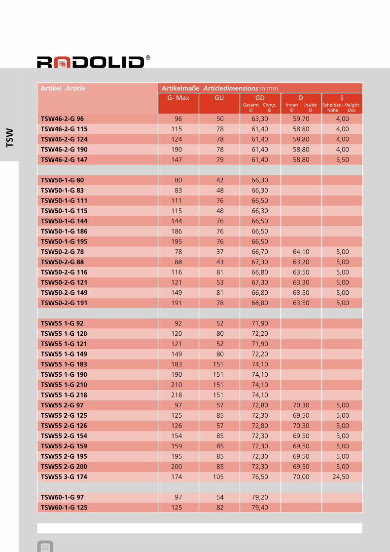
22
Artikelmaße Articledimensions in mmArtikel ArticleG- Max GU GD D S
TSW
TSW46-2-G 96 96 50 63,30 59,70 4,00
TSW46-2-G 115 115 78 61,40 58,80 4,00
TSW46-2-G 124 124 78 61,40 58,80 4,00
TSW46-2-G 190 190 78 61,40 58,80 4,00
TSW46-2-G 147 147 79 61,40 58,80 5,50
TSW50-1-G 80 80 42 66,30
TSW50-1-G 83 83 48 66,30
TSW50-1-G 111 111 76 66,50
TSW50-1-G 115 115 48 66,30
TSW50-1-G 144 144 76 66,50
TSW50-1-G 186 186 76 66,50
TSW50-1-G 195 195 76 66,50
TSW50-2-G 78 78 37 66,70 64,10 5,00
TSW50-2-G 88 88 43 67,30 63,20 5,00
TSW50-2-G 116 116 81 66,80 63,50 5,00
TSW50-2-G 121 121 53 67,30 63,30 5,00
TSW50-2-G 149 149 81 66,80 63,50 5,00
TSW50-2-G 191 191 78 66,80 63,50 5,00
TSW55 1-G 92 92 52 71,90
TSW55 1-G 120 120 80 72,20
TSW55 1-G 121 121 52 71,90
TSW55 1-G 149 149 80 72,20
TSW55 1-G 183 183 151 74,10
TSW55 1-G 190 190 151 74,10
TSW55 1-G 210 210 151 74,10
TSW55 1-G 218 218 151 74,10
TSW55 2-G 97 97 57 72,80 70,30 5,00
TSW55 2-G 125 125 85 72,30 69,50 5,00
TSW55 2-G 126 126 57 72,80 70,30 5,00
TSW55 2-G 154 154 85 72,30 69,50 5,00
TSW55 2-G 159 159 85 72,30 69,50 5,00
TSW55 2-G 195 195 85 72,30 69,50 5,00
TSW55 2-G 200 200 85 72,30 69,50 5,00
TSW55 3-G 174 174 105 76,50 70,00 24,50
TSW60-1-G 97 97 54 79,20
TSW60-1-G 125 125 82 79,40
Comp.Ø
GesamtØ
InsideØ
InnenØ
SW Ausführung Type 1 Ausführung Type 2
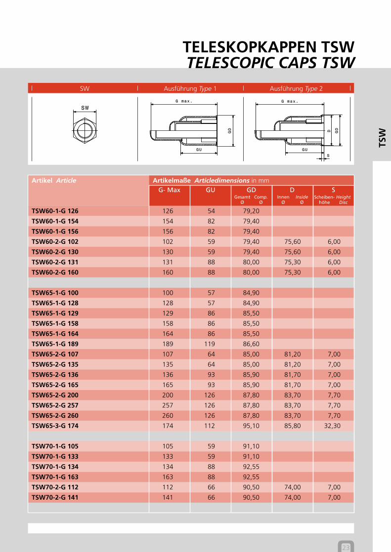
TELESKOPKAPPEN TSWTELESCOPIC CAPS TSW
HeightDisc
Scheiben-höhe
23
Artikelmaße Articledimensions in mmArtikel ArticleG- Max GU GD D S
TSW
TSW60-1-G 126 126 54 79,20
TSW60-1-G 154 154 82 79,40
TSW60-1-G 156 156 82 79,40
TSW60-2-G 102 102 59 79,40 75,60 6,00
TSW60-2-G 130 130 59 79,40 75,60 6,00
TSW60-2-G 131 131 88 80,00 75,30 6,00
TSW60-2-G 160 160 88 80,00 75,30 6,00
TSW65-1-G 100 100 57 84,90
TSW65-1-G 128 128 57 84,90
TSW65-1-G 129 129 86 85,50
TSW65-1-G 158 158 86 85,50
TSW65-1-G 164 164 86 85,50
TSW65-1-G 189 189 119 86,60
TSW65-2-G 107 107 64 85,00 81,20 7,00
TSW65-2-G 135 135 64 85,00 81,20 7,00
TSW65-2-G 136 136 93 85,90 81,70 7,00
TSW65-2-G 165 165 93 85,90 81,70 7,00
TSW65-2-G 200 200 126 87,80 83,70 7,70
TSW65-2-G 257 257 126 87,80 83,70 7,70
TSW65-2-G 260 260 126 87,80 83,70 7,70
TSW65-3-G 174 174 112 95,10 85,80 32,30
TSW70-1-G 105 105 59 91,10
TSW70-1-G 133 133 59 91,10
TSW70-1-G 134 134 88 92,55
TSW70-1-G 163 163 88 92,55
TSW70-2-G 112 112 66 90,50 74,00 7,00
TSW70-2-G 141 141 66 90,50 74,00 7,00
Comp.Ø
GesamtØ
InsideØ
InnenØ
HeightDisc
Scheiben-höhe
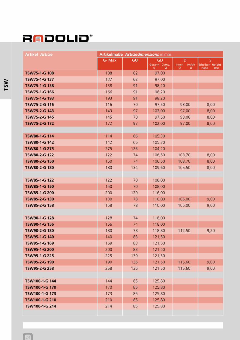
24
Artikelmaße Articledimensions in mmArtikel ArticleG- Max GU GD D S
TSW
TSW75-1-G 108 108 62 97,00
TSW75-1-G 137 137 62 97,00
TSW75-1-G 138 138 91 98,20
TSW75-1-G 166 166 91 98,20
TSW75-1-G 193 193 91 98,20
TSW75-2-G 116 116 70 97,50 93,00 8,00
TSW75-2-G 143 143 97 102,00 97,00 8,00
TSW75-2-G 145 145 70 97,50 93,00 8,00
TSW75-2-G 172 172 97 102,00 97,00 8,00
TSW80-1-G 114 114 66 105,30
TSW80-1-G 142 142 66 105,30
TSW80-1-G 275 275 125 104,20
TSW80-2-G 122 122 74 106,50 103,70 8,00
TSW80-2-G 150 150 74 106,50 103,70 8,00
TSW80-2-G 180 180 134 109,60 105,50 8,00
TSW85-1-G 122 122 70 108,00
TSW85-1-G 150 150 70 108,00
TSW85-1-G 200 200 129 116,00
TSW85-2-G 130 130 78 110,00 105,00 9,00
TSW85-2-G 158 158 78 110,00 105,00 9,00
TSW90-1-G 128 128 74 118,00
TSW90-1-G 156 156 74 118,00
TSW90-2-G 180 180 78 118,80 112,50 9,20
TSW95-1-G 140 140 83 121,50
TSW95-1-G 169 169 83 121,50
TSW95-1-G 200 200 83 121,50
TSW95-1-G 225 225 139 121,30
TSW95-2-G 190 190 136 121,50 115,60 9,00
TSW95-2-G 258 258 136 121,50 115,60 9,00
TSW100-1-G 144 144 85 125,80
TSW100-1-G 170 170 85 125,80
TSW100-1-G 173 173 85 125,80
TSW100-1-G 210 210 85 125,80
TSW100-1-G 214 214 85 125,80
Comp.Ø
GesamtØ
InsideØ
InnenØ
SW Ausführung Type 1 Ausführung Type 2
TELESKOPKAPPEN TSWTELESCOPIC CAPS TSW
HeightDisc
Scheiben-höhe
25
Artikelmaße Articledimensions in mmArtikel ArticleG- Max GU GD D S
TSW
TSW105-1-G 147 147 85 134,00
TSW105-1-G 176 176 85 134,00
TSW105-1-G 204 204 145 133,20
TSW105-1-G 233 233 145 133,20
TSW105-1-G 270 270 145 133,20
TSW107-1-G 210 210 90 133,80
TSW115-1-G 165 165 92 153,90
TSW115-1-G 219 219 92 153,90
TSW117-1-G 175 175 95 148,10
TSW130-1-G 190 190 101 174,80
TSW130-1-G 235 235 101 174,80
TSW135-1-G 185 185 110 172,20
TSW135-1-G 200 200 110 172,20
TSW135-1-G 220 220 110 172,20
TSW135-1-G 290 290 110 172,20
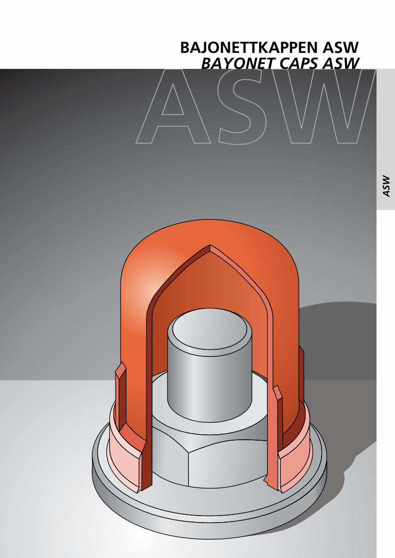
BAJONETTKAPPEN ASWBAYONET CAPS ASW
ASW
ASW
28
ASW
RADOLID-Artikelnummer Article number:
ASW 55-1-G76 PE Black1 2 3 4 5
1 Schlüsselweite Width across flats2 Ausführung Type3 Gesamtinnenhöhe Total heigth inside4 Material Material5 Farbe Colour
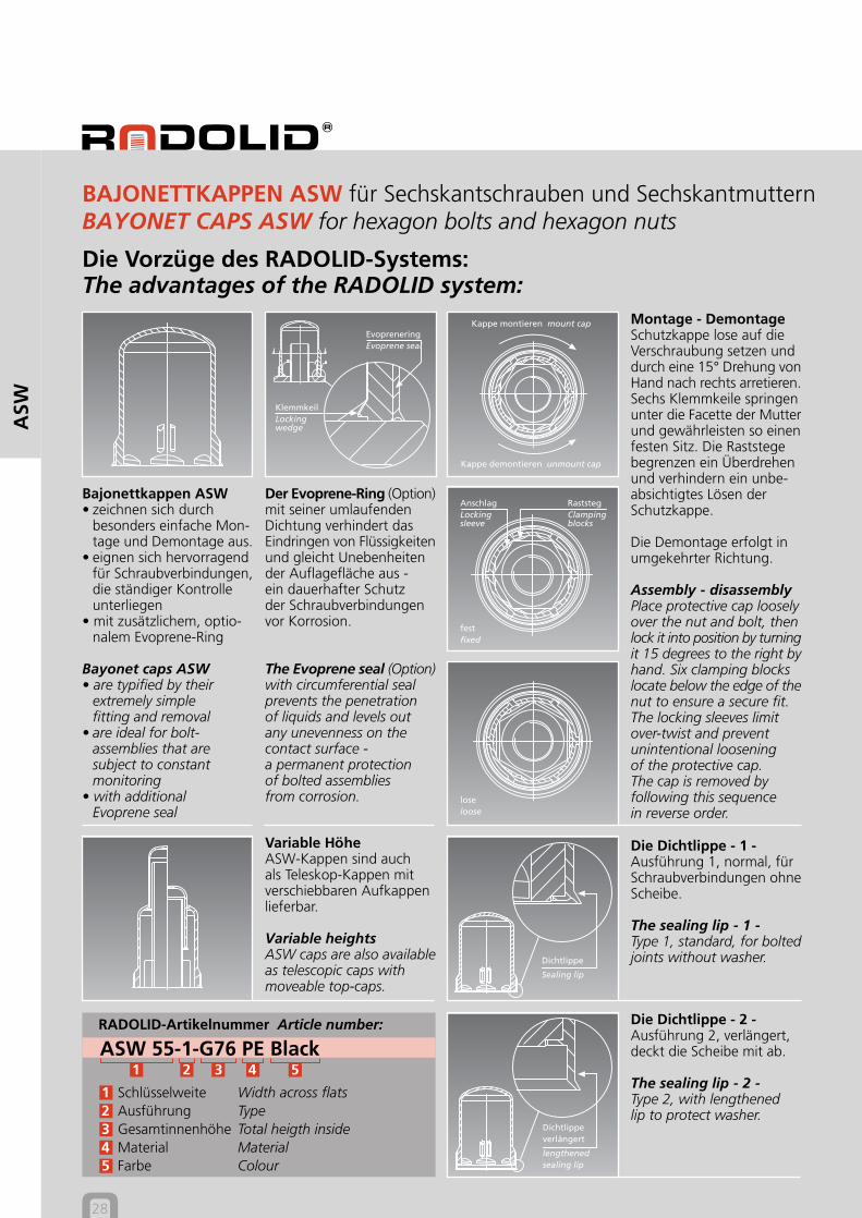
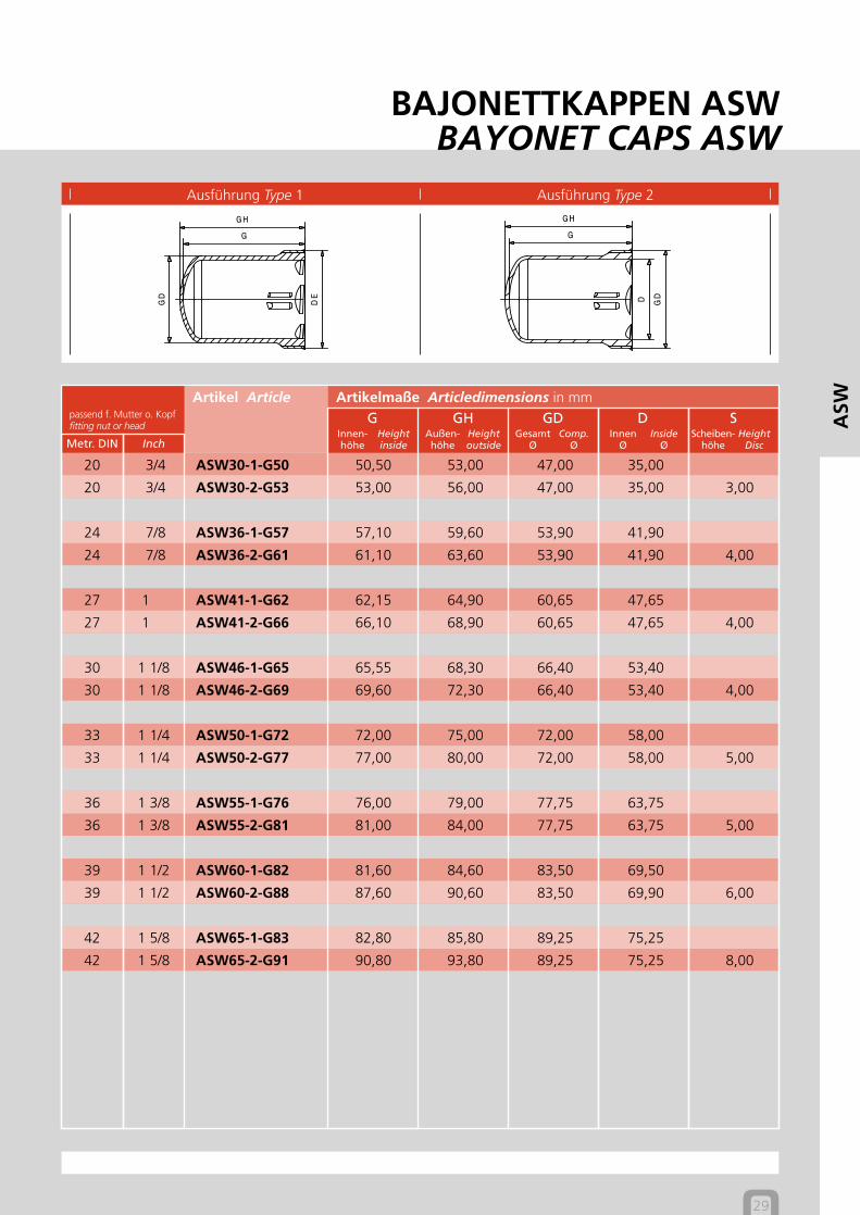
BAJONETTKAPPEN ASW für Sechskantschrauben und SechskantmutternBAYONET CAPS ASW for hexagon bolts and hexagon nuts
Die Vorzüge des RADOLID-Systems:The advantages of the RADOLID system:
KlemmkeilLockingwedge
EvopreneringEvoprene seal
Kappe montieren mount cap
Kappe demontieren unmount cap
festfixed
RaststegClampingblocks
AnschlagLockingsleeve
loseloose
Der Evoprene-Ring (Option)mit seiner umlaufendenDichtung verhindert dasEindringen von Flüssigkeitenund gleicht Unebenheitender Auflagefläche aus -ein dauerhafter Schutzder Schraubverbindungenvor Korrosion.
The Evoprene seal (Option)with circumferential sealprevents the penetrationof liquids and levels outany unevenness on thecontact surface -a permanent protectionof bolted assembliesfrom corrosion.
Bajonettkappen ASW• zeichnen sich durch
besonders einfache Mon-tage und Demontage aus.
• eignen sich hervorragendfür Schraubverbindungen,die ständiger Kontrolleunterliegen
• mit zusätzlichem, optio-nalem Evoprene-Ring
Bayonet caps ASW• are typified by their
extremely simplefitting and removal
• are ideal for bolt-assemblies that aresubject to constantmonitoring
• with additionalEvoprene seal
Montage - DemontageSchutzkappe lose auf dieVerschraubung setzen unddurch eine 15° Drehung vonHand nach rechts arretieren.Sechs Klemmkeile springenunter die Facette der Mutterund gewährleisten so einenfesten Sitz. Die Raststegebegrenzen ein Überdrehenund verhindern ein unbe-absichtigtes Lösen derSchutzkappe.
Die Demontage erfolgt inumgekehrter Richtung.
Assembly - disassemblyPlace protective cap looselyover the nut and bolt, thenlock it into position by turningit 15 degrees to the right byhand. Six clamping blockslocate below the edge of thenut to ensure a secure fit.The locking sleeves limitover-twist and preventunintentional looseningof the protective cap.The cap is removed byfollowing this sequencein reverse order.
Die Dichtlippe - 1 -Ausführung 1, normal, fürSchraubverbindungen ohneScheibe.
The sealing lip - 1 -Type 1, standard, for boltedjoints without washer.
Die Dichtlippe - 2 -Ausführung 2, verlängert,deckt die Scheibe mit ab.
The sealing lip - 2 -Type 2, with lengthenedlip to protect washer.
Dichtlippe
Sealing lip
Dichtlippeverlängert
lengthenedsealing lip
Variable HöheASW-Kappen sind auchals Teleskop-Kappen mitverschiebbaren Aufkappenlieferbar.
Variable heightsASW caps are also availableas telescopic caps withmoveable top-caps.
Heightinside
Innen-höhe
Heightoutside
Außen-höhe
Comp.Ø
GesamtØ
InsideØ
InnenØ
HeightDisc
Scheiben-höhe
Ausführung Type 1
BAJONETTKAPPEN ASWBAYONET CAPS ASW
Ausführung Type 2
29
Artikelmaße Articledimensions in mmpassend f. Mutter o. Kopffitting nut or head
Artikel ArticleG GH GD D S
Metr. DIN Inch
ASW
20 3/4 ASW30-1-G50 50,50 53,00 47,00 35,00
20 3/4 ASW30-2-G53 53,00 56,00 47,00 35,00 3,00
24 7/8 ASW36-1-G57 57,10 59,60 53,90 41,90
24 7/8 ASW36-2-G61 61,10 63,60 53,90 41,90 4,00
27 1 ASW41-1-G62 62,15 64,90 60,65 47,65
27 1 ASW41-2-G66 66,10 68,90 60,65 47,65 4,00
30 1 1/8 ASW46-1-G65 65,55 68,30 66,40 53,40
30 1 1/8 ASW46-2-G69 69,60 72,30 66,40 53,40 4,00
33 1 1/4 ASW50-1-G72 72,00 75,00 72,00 58,00
33 1 1/4 ASW50-2-G77 77,00 80,00 72,00 58,00 5,00
36 1 3/8 ASW55-1-G76 76,00 79,00 77,75 63,75
36 1 3/8 ASW55-2-G81 81,00 84,00 77,75 63,75 5,00
39 1 1/2 ASW60-1-G82 81,60 84,60 83,50 69,50
39 1 1/2 ASW60-2-G88 87,60 90,60 83,50 69,90 6,00
42 1 5/8 ASW65-1-G83 82,80 85,80 89,25 75,25
42 1 5/8 ASW65-2-G91 90,80 93,80 89,25 75,25 8,00
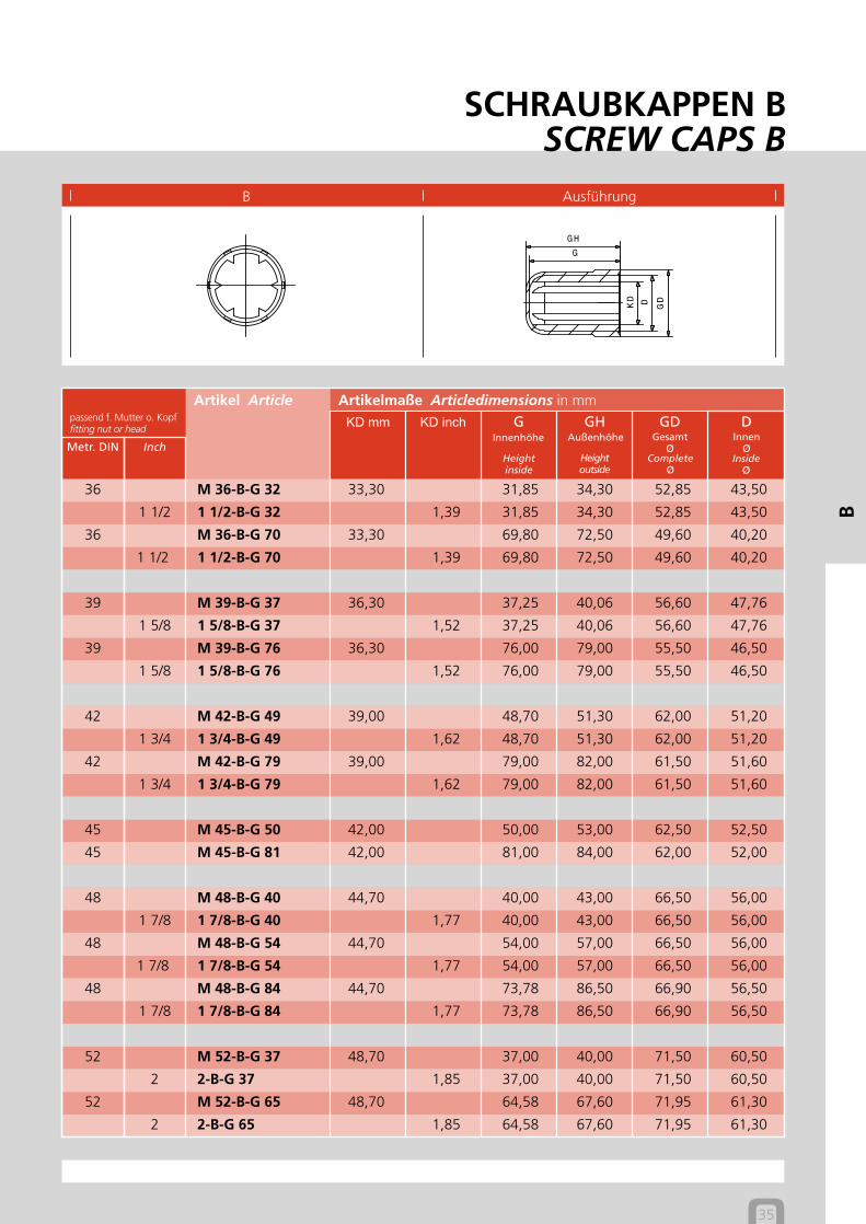
SCHRAUBKAPPEN BSCREW CAPS B
B
B
32
B
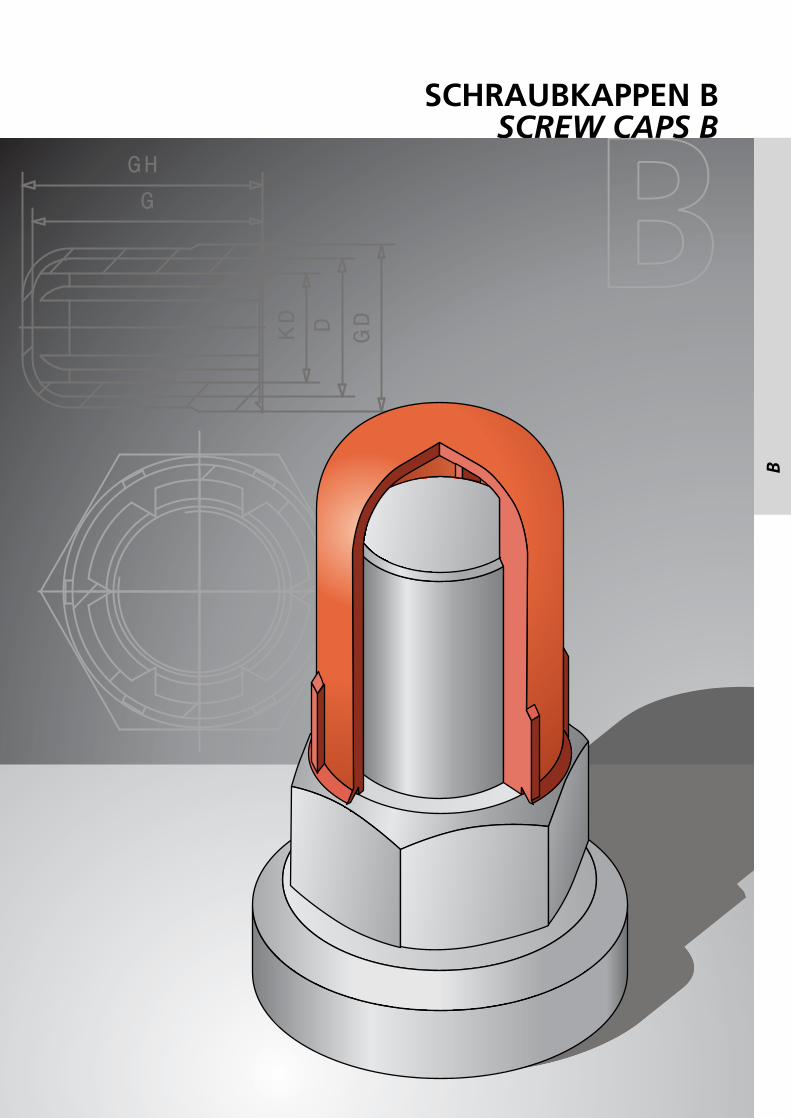
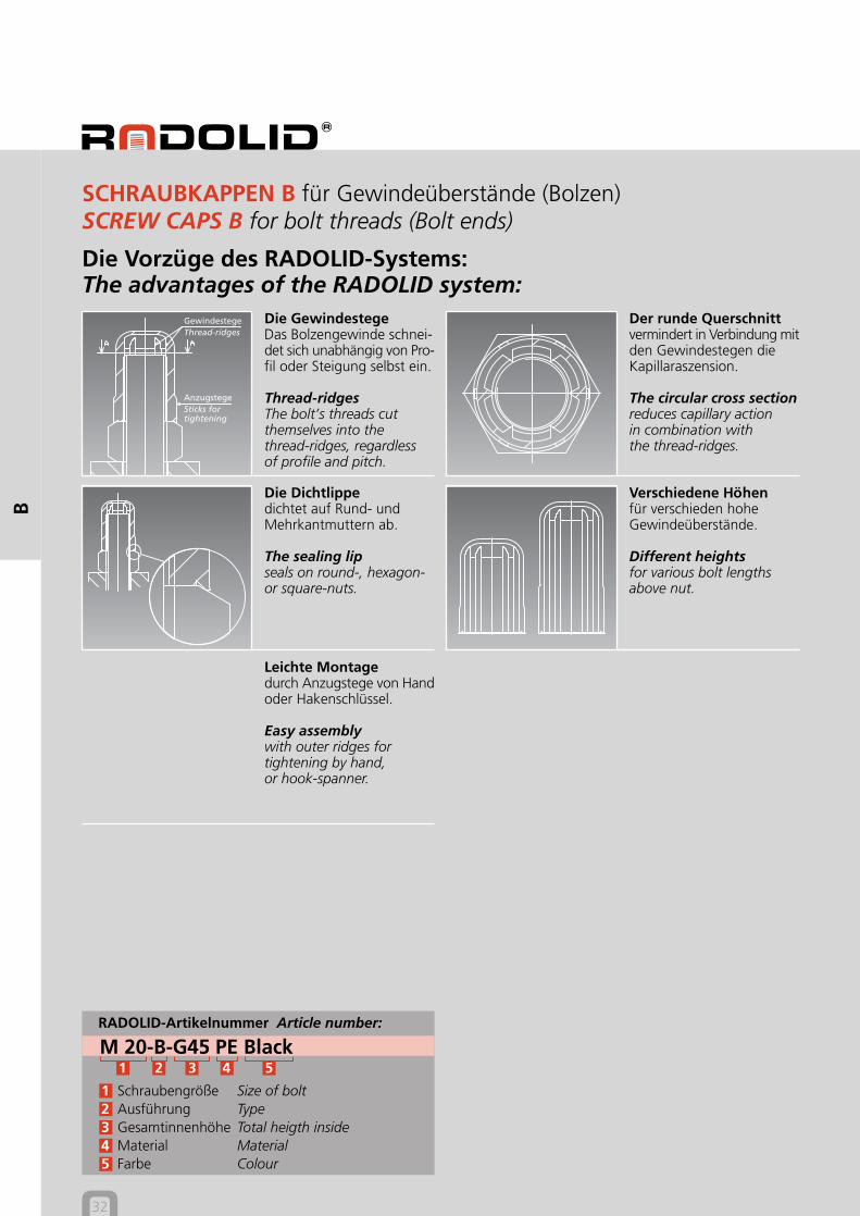
Verschiedene Höhenfür verschieden hoheGewindeüberstände.
Different heightsfor various bolt lengthsabove nut.
GewindestegeThread-ridges
AnzugstegeSticks fortightening
Leichte Montagedurch Anzugstege von Handoder Hakenschlüssel.
Easy assemblywith outer ridges fortightening by hand,or hook-spanner.
RADOLID-Artikelnummer Article number:
M 20-B-G45 PE Black1 2 3 4 5
1 Schraubengröße Size of bolt2 Ausführung Type3 Gesamtinnenhöhe Total heigth inside4 Material Material5 Farbe Colour
SCHRAUBKAPPEN B für Gewindeüberstände (Bolzen)SCREW CAPS B for bolt threads (Bolt ends)
Die Dichtlippedichtet auf Rund- undMehrkantmuttern ab.
The sealing lipseals on round-, hexagon-or square-nuts.
Die GewindestegeDas Bolzengewinde schnei-det sich unabhängig von Pro-fil oder Steigung selbst ein.
Thread-ridgesThe bolt’s threads cutthemselves into thethread-ridges, regardlessof profile and pitch.
Der runde Querschnittvermindert in Verbindung mitden Gewindestegen dieKapillaraszension.
The circular cross sectionreduces capillary actionin combination withthe thread-ridges.
Die Vorzüge des RADOLID-Systems:The advantages of the RADOLID system:

B Ausführung
SCHRAUBKAPPEN BSCREW CAPS B
Heightinside
Innenhöhe
Heightoutside
Außenhöhe
CompleteØ
GesamtØ
InsideØ
InnenØ
33
Artikelmaße Articledimensions in mmpassend f. Mutter o. Kopffitting nut or head
Artikel Article
Metr. DIN Inch
B
KD mm KD inch G GH GD D
6 M 6-B-G 6 5,40 6,30 7,10 10,50 7,00
6 M 6-B-G 12 5,40 11,30 12,90 10,70 7,00
6 M 6-B-G 17 5,40 16,70 18,20 10,90 6,92
8 M 8-B-G 12 7,20 12,03 13,18 13,47 9,20
5/16 5/16-B-G 12 0,28 12,03 13,18 13,47 9,20
8 M 8-B-G 22 7,20 21,50 22,60 12,80 9,20
5/16 5/16-B-G 22 0,28 21,50 22,60 12,80 9,20
10 M 10-B-G 15 9,00 14,80 15,80 15,00 12,00
3/8 3/8-B-G 15 0,33 14,80 15,80 15,00 12,00
10 M 10-B-G 25 9,00 24,60 25,60 15,11 11,13
3/8 3/8-B-G 25 0,33 24,60 25,60 15,11 11,13
12 M 12-B-G 15 10,90 14,40 15,95 17,85 13,02
1/2 1/2-B-G 15 0,45 14,40 15,95 17,85 13,02
12 M 12-B-G 27 10,90 36,30 27,70 18,20 13,10
1/2 1/2-B-G 27 0,45 36,30 27,70 18,20 13,10
14 M 14-B-G 15 12,70 15,00 16,00 21,00 15,00
9/16 9/16-B-G 15 0,51 15,00 16,00 21,00 15,00
14 M 14-B-G 32 12,70 32,00 33,00 21,00 15,00
9/16 9/16-B-G 32 0,51 32,00 33,00 21,00 15,00
16 M 16-B-G 15 14,70 15,00 16,85 22,72 17,00
5/8 5/8-B-G 15 0,56 15,00 16,85 22,72 17,00
16 M 16-B-G 36 14,70 36,00 37,00 23,00 17,00
5/8 5/8-B-G 36 0,56 36,00 37,00 23,00 17,00
Heightinside
Innenhöhe
Heightoutside
Außenhöhe
CompleteØ
GesamtØ
InsideØ
InnenØ
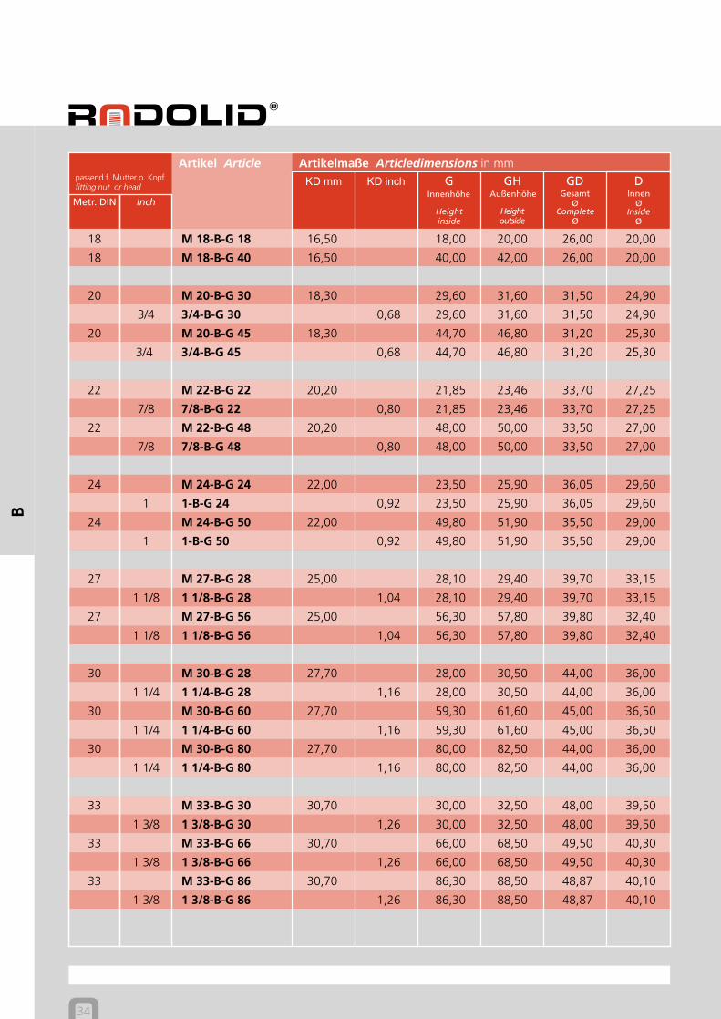
34
Artikelmaße Articledimensions in mmpassend f. Mutter o. Kopffitting nut or head
Artikel Article
KD mm KD inch G GH GD D
Metr. DIN Inch
B
18 M 18-B-G 18 16,50 18,00 20,00 26,00 20,00
18 M 18-B-G 40 16,50 40,00 42,00 26,00 20,00
20 M 20-B-G 30 18,30 29,60 31,60 31,50 24,90
3/4 3/4-B-G 30 0,68 29,60 31,60 31,50 24,90
20 M 20-B-G 45 18,30 44,70 46,80 31,20 25,30
3/4 3/4-B-G 45 0,68 44,70 46,80 31,20 25,30
22 M 22-B-G 22 20,20 21,85 23,46 33,70 27,25
7/8 7/8-B-G 22 0,80 21,85 23,46 33,70 27,25
22 M 22-B-G 48 20,20 48,00 50,00 33,50 27,00
7/8 7/8-B-G 48 0,80 48,00 50,00 33,50 27,00
24 M 24-B-G 24 22,00 23,50 25,90 36,05 29,60
1 1-B-G 24 0,92 23,50 25,90 36,05 29,60
24 M 24-B-G 50 22,00 49,80 51,90 35,50 29,00
1 1-B-G 50 0,92 49,80 51,90 35,50 29,00
27 M 27-B-G 28 25,00 28,10 29,40 39,70 33,15
1 1/8 1 1/8-B-G 28 1,04 28,10 29,40 39,70 33,15
27 M 27-B-G 56 25,00 56,30 57,80 39,80 32,40
1 1/8 1 1/8-B-G 56 1,04 56,30 57,80 39,80 32,40
30 M 30-B-G 28 27,70 28,00 30,50 44,00 36,00
1 1/4 1 1/4-B-G 28 1,16 28,00 30,50 44,00 36,00
30 M 30-B-G 60 27,70 59,30 61,60 45,00 36,50
1 1/4 1 1/4-B-G 60 1,16 59,30 61,60 45,00 36,50
30 M 30-B-G 80 27,70 80,00 82,50 44,00 36,00
1 1/4 1 1/4-B-G 80 1,16 80,00 82,50 44,00 36,00
33 M 33-B-G 30 30,70 30,00 32,50 48,00 39,50
1 3/8 1 3/8-B-G 30 1,26 30,00 32,50 48,00 39,50
33 M 33-B-G 66 30,70 66,00 68,50 49,50 40,30
1 3/8 1 3/8-B-G 66 1,26 66,00 68,50 49,50 40,30
33 M 33-B-G 86 30,70 86,30 88,50 48,87 40,10
1 3/8 1 3/8-B-G 86 1,26 86,30 88,50 48,87 40,10
B Ausführung
SCHRAUBKAPPEN BSCREW CAPS B
Heightinside
Innenhöhe
Heightoutside
Außenhöhe
CompleteØ
GesamtØ
InsideØ
InnenØ
35
Artikelmaße Articledimensions in mmpassend f. Mutter o. Kopffitting nut or head
Artikel Article
Metr. DIN Inch
B
KD mm KD inch G GH GD D
36 M 36-B-G 32 33,30 31,85 34,30 52,85 43,50
1 1/2 1 1/2-B-G 32 1,39 31,85 34,30 52,85 43,50
36 M 36-B-G 70 33,30 69,80 72,50 49,60 40,20
1 1/2 1 1/2-B-G 70 1,39 69,80 72,50 49,60 40,20
39 M 39-B-G 37 36,30 37,25 40,06 56,60 47,76
1 5/8 1 5/8-B-G 37 1,52 37,25 40,06 56,60 47,76
39 M 39-B-G 76 36,30 76,00 79,00 55,50 46,50
1 5/8 1 5/8-B-G 76 1,52 76,00 79,00 55,50 46,50
42 M 42-B-G 49 39,00 48,70 51,30 62,00 51,20
1 3/4 1 3/4-B-G 49 1,62 48,70 51,30 62,00 51,20
42 M 42-B-G 79 39,00 79,00 82,00 61,50 51,60
1 3/4 1 3/4-B-G 79 1,62 79,00 82,00 61,50 51,60
45 M 45-B-G 50 42,00 50,00 53,00 62,50 52,50
45 M 45-B-G 81 42,00 81,00 84,00 62,00 52,00
48 M 48-B-G 40 44,70 40,00 43,00 66,50 56,00
1 7/8 1 7/8-B-G 40 1,77 40,00 43,00 66,50 56,00
48 M 48-B-G 54 44,70 54,00 57,00 66,50 56,00
1 7/8 1 7/8-B-G 54 1,77 54,00 57,00 66,50 56,00
48 M 48-B-G 84 44,70 73,78 86,50 66,90 56,50
1 7/8 1 7/8-B-G 84 1,77 73,78 86,50 66,90 56,50
52 M 52-B-G 37 48,70 37,00 40,00 71,50 60,50
2 2-B-G 37 1,85 37,00 40,00 71,50 60,50
52 M 52-B-G 65 48,70 64,58 67,60 71,95 61,30
2 2-B-G 65 1,85 64,58 67,60 71,95 61,30
Heightinside
Innenhöhe
Heightoutside
Außenhöhe
CompleteØ
GesamtØ
InsideØ
InnenØ
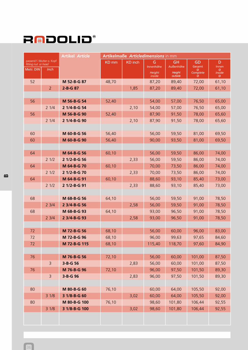
36
Artikelmaße Articledimensions in mmpassend f. Mutter o. Kopffitting nut or head
Artikel Article
KD mm KD inch G GH GD D
Metr. DIN Inch
B
52 M 52-B-G 87 48,70 87,20 89,40 72,00 61,10
2 2-B-G 87 1,85 87,20 89,40 72,00 61,10
56 M 56-B-G 54 52,40 54,00 57,00 76,50 65,00
2 1/4 2 1/4-B-G 54 2,10 54,00 57,00 76,50 65,00
56 M 56-B-G 90 52,40 87,90 91,50 78,00 65,60
2 1/4 2 1/4-B-G 90 2,10 87,90 91,50 78,00 65,60
60 M 60-B-G 56 56,40 56,00 59,50 81,00 69,50
60 M 60-B-G 90 56,40 90,00 93,50 81,00 69,50
64 M 64-B-G 56 60,10 56,00 59,50 86,00 74,00
2 1/2 2 1/2-B-G 56 2,33 56,00 59,50 86,00 74,00
64 M 64-B-G 70 60,10 70,00 73,50 86,00 74,00
2 1/2 2 1/2-B-G 70 2,33 70,00 73,50 86,00 74,00
64 M 64-B-G 91 60,10 88,60 93,10 85,40 73,00
2 1/2 2 1/2-B-G 91 2,33 88,60 93,10 85,40 73,00
68 M 68-B-G 56 64,10 56,00 59,50 91,00 78,50
2 3/4 2 3/4-B-G 56 2,58 56,00 59,50 91,00 78,50
68 M 68-B-G 93 64,10 93,00 96,50 91,00 78,50
2 3/4 2 3/4-B-G 93 2,58 93,00 96,50 91,00 78,50
72 M 72-B-G 56 68,10 56,00 60,00 96,00 83,00
72 M 72-B-G 96 68,10 96,00 99,63 97,65 84,60
72 M 72-B-G 115 68,10 115,40 118,70 97,60 84,90
76 M 76-B-G 56 72,10 56,00 60,00 101,00 87,50
3 3-B-G 56 2,83 56,00 60,00 101,00 87,50
76 M 76-B-G 96 72,10 96,00 97,50 101,50 89,30
3 3-B-G 96 2,83 96,00 97,50 101,50 89,30
80 M 80-B-G 60 76,10 60,00 64,00 105,50 92,00
3 1/8 3 1/8-B-G 60 3,02 60,00 64,00 105,50 92,00
80 M 80-B-G 100 76,10 98,60 101,80 106,44 92,55
3 1/8 3 1/8-B-G 100 3,02 98,60 101,80 106,44 92,55

B Ausführung
SCHRAUBKAPPEN BSCREW CAPS B
Heightinside
Innenhöhe
Heightoutside
Außenhöhe
CompleteØ
GesamtØ
InsideØ
InnenØ
37
Artikelmaße Articledimensions in mmpassend f. Mutter o. Kopffitting nut or head
Artikel Article
Metr. DIN Inch
B
KD mm KD inch G GH GD D
85 M 85-B-G 100 78,04 100,00 104,00 105,50 92,00
3 1/4 3 1/4-B-G 100 3,09 100,00 104,00 105,50 92,00
90 M 90-B-G 64 86,10 64,00 68,00 115,50 102,00
3 1/2 3 1/2-B-G 64 3,34 64,00 68,00 115,50 102,00
90 M 90-B-G 100 86,10 98,70 102,00 116,90 104,24
3 1/2 3 1/2-B-G 100 3,34 98,70 102,00 116,90 104,24
100 M 100-B-G 76 96,10 76,00 81,00 129,00 112,00
3 3/4 3 3/4-B-G 76 3,59 76,00 81,00 129,00 112,00
100 M 100-B-G 105 96,10 105,00 110,00 129,00 112,00
3 3/4 3 3/4-B-G 105 3,59 105,00 110,00 129,00 112,00
4 4-B-G 150 3,84 105,00 110,00 129,00 112,00
110 M 110-B-G 76 106,10 76,00 81,00 139,00 122,50
4 1/4 4 1/4-B-G 76 4,14 76,00 81,00 139,00 122,50
110 M 110-B-G 105 106,10 102,70 106,80 141,50 124,20
4 1/4 4 1/4-B-G 105 4,14 102,70 106,80 141,50 124,20
4 1/2 4 1/2-B-G 105 4,39 105,00 110,00 139,00 122,50
120 M 120-B-G 126 116,10 126,00 131,00 152,00 135,00
4 3/4 4 3/4-B-G 126 4,64 126,00 131,00 152,00 135,00
125 M 125-B-G 126 121,10 125,00 129,40 150,20 133,40
5 5-B-G 126 4,89 125,00 129,40 150,20 133,40
Heightinside
Innenhöhe
Heightoutside
Außenhöhe
CompleteØ
GesamtØ
InsideØ
InnenØ
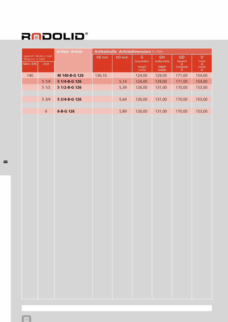
38
Artikelmaße Articledimensions in mmpassend f. Mutter o. Kopffitting nut or head
Artikel Article
KD mm KD inch G GH GD D
Metr. DIN Inch
B
140 M 140-B-G 126 136,10 124,00 129,00 171,00 154,00
5 1/4 5 1/4-B-G 126 5,14 124,00 129,00 171,00 154,00
5 1/2 5 1/2-B-G 126 5,39 126,00 131,00 170,00 153,00
5 3/4 5 3/4-B-G 126 5,64 126,00 131,00 170,00 153,00
6 6-B-G 126 5,89 126,00 131,00 170,00 153,00
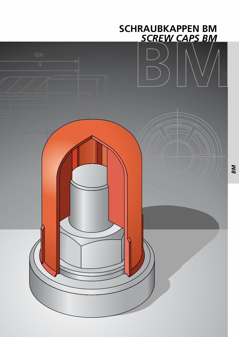
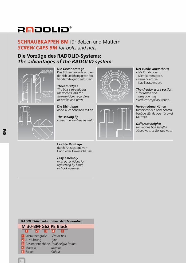
SCHRAUBKAPPEN BMSCREW CAPS BM
BM
BM
40
BM
RADOLID-Artikelnummer Article number:
M 30-BM-G62 PE Black1 2 3 4 5
1 Schraubengröße Size of bolt2 Ausführung Type3 Gesamtinnenhöhe Total heigth inside4 Material Material5 Farbe Colour
Die Vorzüge des RADOLID-Systems:The advantages of the RADOLID system:
Der runde Querschnitt• für Rund- oder
Mehrkantmuttern.• vermindert die
Kapillaraszension.
The circular cross section• for round and
hexagon nuts• reduces capillary action.
Die GewindestegeDas Bolzengewinde schnei-det sich unabhängig von Pro-fil oder Steigung selbst ein.
Thread-ridgesThe bolt’s threads cutthemselves into thethread-ridges,regardlessof profile and pitch.
Die Dichtlippedeckt auch Scheiben mit ab.
The sealing lipcovers the washers as well.
SCHRAUBKAPPEN BM für Bolzen und MutternSCREW CAPS BM for bolts and nuts
Verschiedene Höhenfür verschieden hohe Schrau-benüberstände oder für zweiMuttern.
Different heightsfor various bolt lengthsabove nuts or for two nuts.
GewindestegeThread-ridges
AnzugstegeSticks fortightening
Leichte Montagedurch Anzugstege vonHand oder Hakenschlüssel.
Easy assemblywith outer ridges fortightening by hand,or hook-spanner.
Heightinside
Innenhöhe
Heightoutside
Außenhöhe
CompleteØ
GesamtØ
InsideØ
InnenØ
BM Ausführung
SCHRAUBKAPPEN BMSCREW CAPS BM
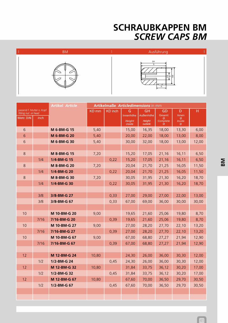
41
Artikelmaße Articledimensions in mmpassend f. Mutter o. Kopffitting nut or head
Artikel Article KD mm KD inch G GH GD D H
Metr. DIN Inch
BM
6 M 6-BM-G 15 5,40 15,00 16,35 18,00 13,30 6,00
6 M 6-BM-G 20 5,40 20,00 22,00 18,00 13,00 8,00
6 M 6-BM-G 30 5,40 30,00 32,00 18,00 13,00 12,00
8 M 8-BM-G 15 7,20 15,20 17,05 21,16 16,11 6,50
1/4 1/4-BM-G 15 0,22 15,20 17,05 21,16 16,11 6,50
8 M 8-BM-G 20 7,20 20,04 21,70 21,25 16,05 11,50
1/4 1/4-BM-G 20 0,22 20,04 21,70 21,25 16,05 11,50
8 M 8-BM-G 30 7,20 30,05 31,95 21,30 16,20 18,70
1/4 1/4-BM-G 30 0,22 30,05 31,95 21,30 16,20 18,70
3/8 3/8-BM-G 27 0,33 27,00 29,00 27,00 22,00 13,00
3/8 3/8-BM-G 67 0,33 67,00 69,00 36,00 30,00 30,00
10 M 10-BM-G 20 9,00 19,65 21,60 25,06 19,80 8,70
7/16 7/16-BM-G 20 0,39 19,65 21,60 25,06 19,80 8,70
10 M 10-BM-G 27 9,00 27,00 28,20 27,70 22,10 13,20
7/16 7/16-BM-G 27 0,39 27,00 28,20 27,70 22,10 13,20
10 M 10-BM-G 67 9,00 67,00 68,80 27,27 21,94 12,90
7/16 7/16-BM-G 67 0,39 67,00 68,80 27,27 21,94 12,90
12 M 12-BM-G 24 10,80 24,30 26,00 36,00 30,30 12,00
1/2 1/2-BM-G 24 0,45 24,30 26,00 36,00 30,30 12,00
12 M 12-BM-G 32 10,80 31,84 33,75 36,12 30,20 17,00
1/2 1/2-BM-G 32 0,45 31,84 33,75 36,12 30,20 17,00
12 M 12-BM-G 67 10,80 67,60 70,00 36,50 29,70 30,50
1/2 1/2-BM-G 67 0,45 67,60 70,00 36,50 29,70 30,50
Heightinside
Innenhöhe
Heightoutside
Außenhöhe
CompleteØ
GesamtØ
InsideØ
InnenØ
42
Artikelmaße Articledimensions in mmpassend f. Mutter o. Kopffitting nut or head
Artikel Article KD mm KD inch G GH GD D H
Metr. DIN Inch
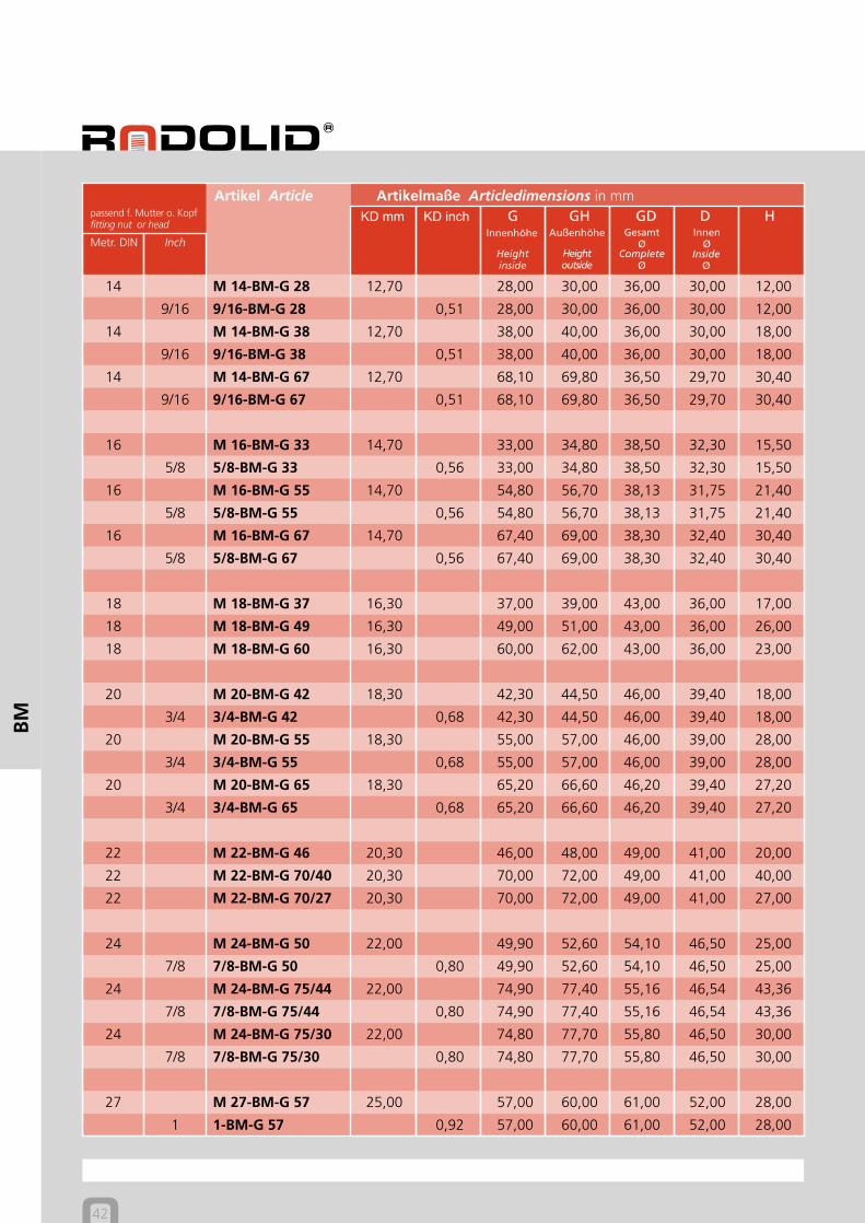
BM
14 M 14-BM-G 28 12,70 28,00 30,00 36,00 30,00 12,00
9/16 9/16-BM-G 28 0,51 28,00 30,00 36,00 30,00 12,00
14 M 14-BM-G 38 12,70 38,00 40,00 36,00 30,00 18,00
9/16 9/16-BM-G 38 0,51 38,00 40,00 36,00 30,00 18,00
14 M 14-BM-G 67 12,70 68,10 69,80 36,50 29,70 30,40
9/16 9/16-BM-G 67 0,51 68,10 69,80 36,50 29,70 30,40
16 M 16-BM-G 33 14,70 33,00 34,80 38,50 32,30 15,50
5/8 5/8-BM-G 33 0,56 33,00 34,80 38,50 32,30 15,50
16 M 16-BM-G 55 14,70 54,80 56,70 38,13 31,75 21,40
5/8 5/8-BM-G 55 0,56 54,80 56,70 38,13 31,75 21,40
16 M 16-BM-G 67 14,70 67,40 69,00 38,30 32,40 30,40
5/8 5/8-BM-G 67 0,56 67,40 69,00 38,30 32,40 30,40
18 M 18-BM-G 37 16,30 37,00 39,00 43,00 36,00 17,00
18 M 18-BM-G 49 16,30 49,00 51,00 43,00 36,00 26,00
18 M 18-BM-G 60 16,30 60,00 62,00 43,00 36,00 23,00
20 M 20-BM-G 42 18,30 42,30 44,50 46,00 39,40 18,00
3/4 3/4-BM-G 42 0,68 42,30 44,50 46,00 39,40 18,00
20 M 20-BM-G 55 18,30 55,00 57,00 46,00 39,00 28,00
3/4 3/4-BM-G 55 0,68 55,00 57,00 46,00 39,00 28,00
20 M 20-BM-G 65 18,30 65,20 66,60 46,20 39,40 27,20
3/4 3/4-BM-G 65 0,68 65,20 66,60 46,20 39,40 27,20
22 M 22-BM-G 46 20,30 46,00 48,00 49,00 41,00 20,00
22 M 22-BM-G 70/40 20,30 70,00 72,00 49,00 41,00 40,00
22 M 22-BM-G 70/27 20,30 70,00 72,00 49,00 41,00 27,00
24 M 24-BM-G 50 22,00 49,90 52,60 54,10 46,50 25,00
7/8 7/8-BM-G 50 0,80 49,90 52,60 54,10 46,50 25,00
24 M 24-BM-G 75/44 22,00 74,90 77,40 55,16 46,54 43,36
7/8 7/8-BM-G 75/44 0,80 74,90 77,40 55,16 46,54 43,36
24 M 24-BM-G 75/30 22,00 74,80 77,70 55,80 46,50 30,00
7/8 7/8-BM-G 75/30 0,80 74,80 77,70 55,80 46,50 30,00
27 M 27-BM-G 57 25,00 57,00 60,00 61,00 52,00 28,00
1 1-BM-G 57 0,92 57,00 60,00 61,00 52,00 28,00

Heightinside
Innenhöhe
Heightoutside
Außenhöhe
CompleteØ
GesamtØ
InsideØ
InnenØ
BM Ausführung
SCHRAUBKAPPEN BMSCREW CAPS BM
43
Artikelmaße Articledimensions in mmpassend f. Mutter o. Kopffitting nut or head
Artikel Article KD mm KD inch G GH GD D H
Metr. DIN Inch
BM
27 M 27-BM-G 80/48 25,00 79,40 82,65 63,95 54,56 48,00
1 1-BM-G 80/48 0,92 79,40 82,65 63,95 54,56 48,00
27 M 27-BM-G 80/33 25,00 80,10 82,30 64,05 54,47 33,00
1 1-BM-G 80/33 0,92 80,10 82,30 64,05 54,47 33,00
30 M 30-BM-G 62 27,70 61,50 64,40 68,70 59,00 30,80
1 1/8 1 1/8-BM-G 62 1,04 61,50 64,40 68,70 59,00 30,80
30 M 30-BM-G 95/54 27,70 95,10 98,10 68,85 57,50 53,60
1 1/8 1 1/8-BM-G 95/54 1,04 95,10 98,10 68,85 57,50 53,60
30 M 30-BM-G 95/36 27,70 94,50 97,30 69,00 57,00 36,40
1 1/8 1 1/8-BM-G 95/36 1,04 94,50 97,30 69,00 57,00 36,40
33 M 33-BM-G 69 30,70 69,00 72,00 73,00 62,00 32,00
1 1/4 1 1/4-BM-G 69 1,16 69,00 72,00 73,00 62,00 32,00
33 M 33-BM-G 105/44 30,70 105,00 108,00 73,00 62,00 44,00
1 1/4 1 1/4-BM-G 105/44 1,16 105,00 108,00 73,00 62,00 44,00
33 M 33-BM-G 105/40 30,70 105,00 108,20 73,00 61,60 40,00
1 1/4 1 1/4-BM-G 105/40 1,16 105,00 108,20 73,00 61,60 40,00
36 M 36-BM-G 74 33,30 74,00 78,00 79,00 68,00 32,00
1 3/8 1 3/8-BM-G 74 1,26 74,00 78,00 79,00 68,00 32,00
36 M 36-BM-G 80/45 33,30 79,20 81,10 78,80 67,98 45,80
1 3/8 1 3/8-BM-G 80/45 1,26 79,20 81,10 78,80 67,98 45,80
36 M 36-BM-G 115/65 33,30 113,50 116,40 80,65 69,55 65,00
1 3/8 1 3/8-BM-G 115/65 1,26 113,50 116,40 80,65 69,55 65,00
36 M 36-BM-G 115/43 33,30 114,40 117,70 80,50 69,00 43,00
1 3/8 1 3/8-BM-G 115/43 1,26 114,40 117,70 80,50 69,00 43,00
Heightinside
Innenhöhe
Heightoutside
Außenhöhe
CompleteØ
GesamtØ
InsideØ
InnenØ
44
Artikelmaße Articledimensions in mmpassend f. Mutter o. Kopffitting nut or head
Artikel Article KD mm KD inch G GH GD D H
Metr. DIN Inch
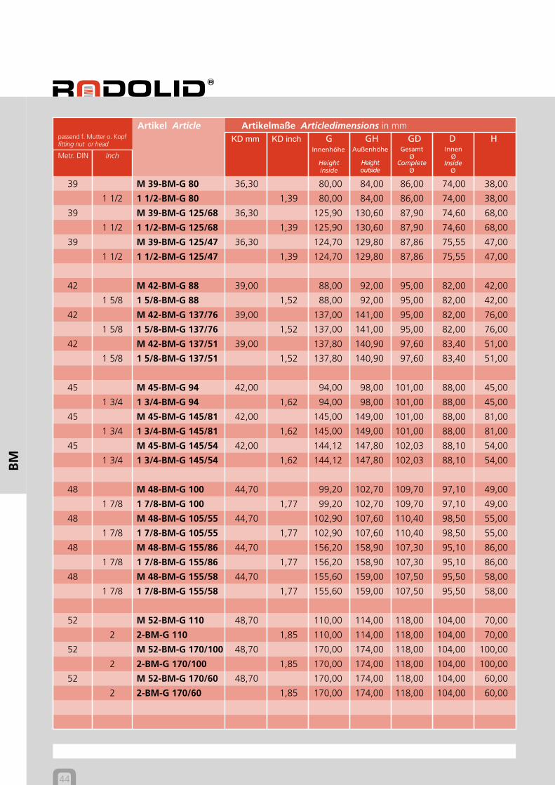
BM
39 M 39-BM-G 80 36,30 80,00 84,00 86,00 74,00 38,00
1 1/2 1 1/2-BM-G 80 1,39 80,00 84,00 86,00 74,00 38,00
39 M 39-BM-G 125/68 36,30 125,90 130,60 87,90 74,60 68,00
1 1/2 1 1/2-BM-G 125/68 1,39 125,90 130,60 87,90 74,60 68,00
39 M 39-BM-G 125/47 36,30 124,70 129,80 87,86 75,55 47,00
1 1/2 1 1/2-BM-G 125/47 1,39 124,70 129,80 87,86 75,55 47,00
42 M 42-BM-G 88 39,00 88,00 92,00 95,00 82,00 42,00
1 5/8 1 5/8-BM-G 88 1,52 88,00 92,00 95,00 82,00 42,00
42 M 42-BM-G 137/76 39,00 137,00 141,00 95,00 82,00 76,00
1 5/8 1 5/8-BM-G 137/76 1,52 137,00 141,00 95,00 82,00 76,00
42 M 42-BM-G 137/51 39,00 137,80 140,90 97,60 83,40 51,00
1 5/8 1 5/8-BM-G 137/51 1,52 137,80 140,90 97,60 83,40 51,00
45 M 45-BM-G 94 42,00 94,00 98,00 101,00 88,00 45,00
1 3/4 1 3/4-BM-G 94 1,62 94,00 98,00 101,00 88,00 45,00
45 M 45-BM-G 145/81 42,00 145,00 149,00 101,00 88,00 81,00
1 3/4 1 3/4-BM-G 145/81 1,62 145,00 149,00 101,00 88,00 81,00
45 M 45-BM-G 145/54 42,00 144,12 147,80 102,03 88,10 54,00
1 3/4 1 3/4-BM-G 145/54 1,62 144,12 147,80 102,03 88,10 54,00
48 M 48-BM-G 100 44,70 99,20 102,70 109,70 97,10 49,00
1 7/8 1 7/8-BM-G 100 1,77 99,20 102,70 109,70 97,10 49,00
48 M 48-BM-G 105/55 44,70 102,90 107,60 110,40 98,50 55,00
1 7/8 1 7/8-BM-G 105/55 1,77 102,90 107,60 110,40 98,50 55,00
48 M 48-BM-G 155/86 44,70 156,20 158,90 107,30 95,10 86,00
1 7/8 1 7/8-BM-G 155/86 1,77 156,20 158,90 107,30 95,10 86,00
48 M 48-BM-G 155/58 44,70 155,60 159,00 107,50 95,50 58,00
1 7/8 1 7/8-BM-G 155/58 1,77 155,60 159,00 107,50 95,50 58,00
52 M 52-BM-G 110 48,70 110,00 114,00 118,00 104,00 70,00
2 2-BM-G 110 1,85 110,00 114,00 118,00 104,00 70,00
52 M 52-BM-G 170/100 48,70 170,00 174,00 118,00 104,00 100,00
2 2-BM-G 170/100 1,85 170,00 174,00 118,00 104,00 100,00
52 M 52-BM-G 170/60 48,70 170,00 174,00 118,00 104,00 60,00
2 2-BM-G 170/60 1,85 170,00 174,00 118,00 104,00 60,00

Heightinside
Innenhöhe
Heightoutside
Außenhöhe
CompleteØ
GesamtØ
InsideØ
InnenØ
BM Ausführung
SCHRAUBKAPPEN BMSCREW CAPS BM
45
Artikelmaße Articledimensions in mmpassend f. Mutter o. Kopffitting nut or head
Artikel Article KD mm KD inch G GH GD D H
Metr. DIN Inch
BM
56 M 56-BM-G 115/60 52,40 113,50 117,40 126,90 112,65 60,00
2 1/4 2 1/4-BM-G 115/60 2,10 113,50 117,40 126,90 112,65 60,00
56 M 56-BM-G 118 52,40 118,00 122,00 121,00 107,00 56,00
2 1/4 2 1/4-BM-G 118 2,10 118,00 122,00 121,00 107,00 56,00
56 M 56-BM-G 180/102 52,40 180,00 184,00 121,00 107,00 102,00
2 1/4 2 1/4-BM G 180/102 2,10 180,00 184,00 121,00 107,00 102,00
56 M 56-BM-G 180/70 52,40 181,20 184,50 119,40 106,10 70,50
2 1/4 2 1/4-BM-G 180/70 2,10 181,20 184,50 119,40 106,10 70,50
60 M 60-BM-G 126 56,40 126,00 130,00 129,00 114,00 59,00
60 M 60-BM-G 180/107 56,40 181,50 184,80 127,50 113,00 107,00
60 M 60-BM-G 180/75 56,40 180,00 184,00 129,00 114,00 75,00
64 M 64-BM-G 134 60,10 133,80 139,50 138,60 122,00 66,00
2 1/2 2 1/2-BM-G 134 2,33 133,80 139,50 138,60 122,00 66,00
64 M 64-BM-G 135/67 60,10 135,00 139,00 138,00 121,00 65,00
2 1/2 2 1/2-BM-G 135/67 2,33 135,00 139,00 138,00 121,00 65,00
64 M 64-BM-G 180/113 60,10 180,70 184,70 140,28 122,60 113,00
2 1/2 2 1/2-BM-G 180/113 2,33 180,70 184,70 140,28 122,60 113,00
64 M 64-BM-G 180/75 60,10 180,90 185,00 139,20 122,20 75,00
2 1/2 2 1/2-BM-G 180/75 2,33 180,90 185,00 139,20 122,20 75,00
68 M 68-BM-G 143 64,10 143,00 148,00 141,00 124,00 66,00
68 M 68-BM-G 180/120 64,10 180,00 185,00 141,00 124,00 120,00
68 M 68-BM-G 180/80 64,10 180,00 185,00 141,00 124,00 80,00
72 M 72-BM-G 152 68,10 152,00 157,00 146,00 129,00 70,00
2 3/4 2 3/4-BM-G 152 2,58 152,00 157,00 146,00 129,00 70,00
Heightinside
Innenhöhe
Heightoutside
Außenhöhe
CompleteØ
GesamtØ
InsideØ
InnenØ
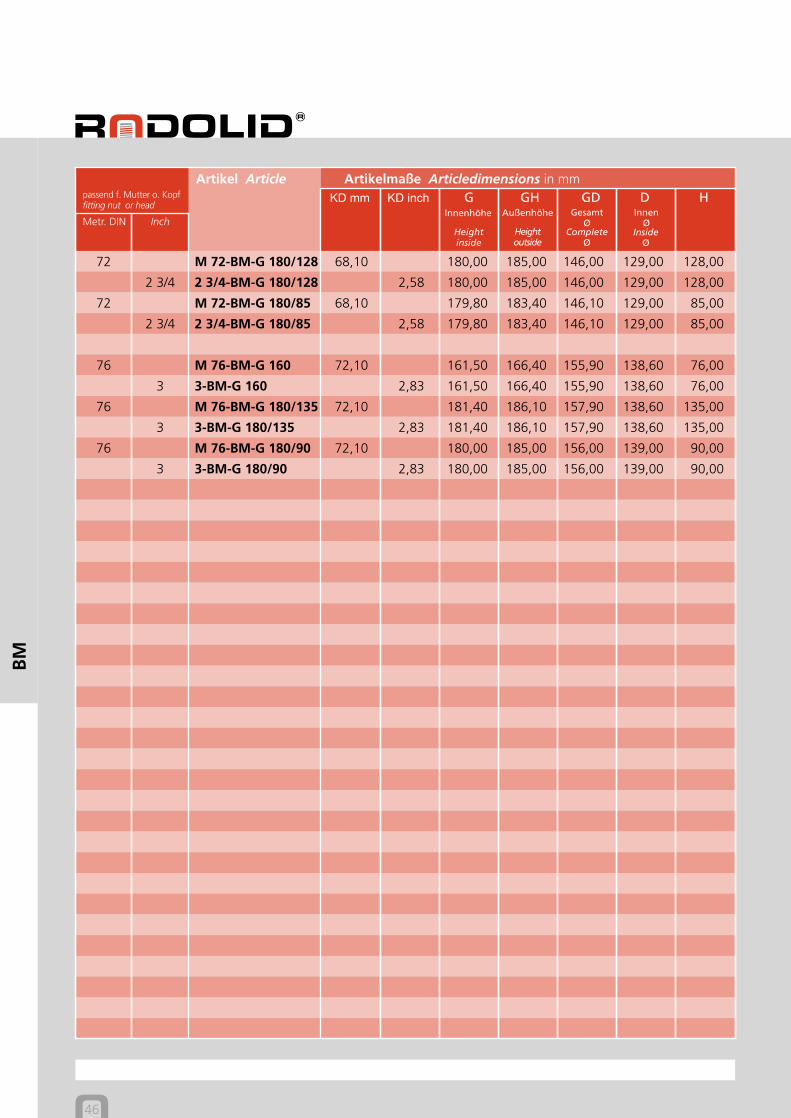
46
Artikelmaße Articledimensions in mmpassend f. Mutter o. Kopffitting nut or head
Artikel Article KD mm KD inch G GH GD D H
Metr. DIN Inch
BM
72 M 72-BM-G 180/128 68,10 180,00 185,00 146,00 129,00 128,00
2 3/4 2 3/4-BM-G 180/128 2,58 180,00 185,00 146,00 129,00 128,00
72 M 72-BM-G 180/85 68,10 179,80 183,40 146,10 129,00 85,00
2 3/4 2 3/4-BM-G 180/85 2,58 179,80 183,40 146,10 129,00 85,00
76 M 76-BM-G 160 72,10 161,50 166,40 155,90 138,60 76,00
3 3-BM-G 160 2,83 161,50 166,40 155,90 138,60 76,00
76 M 76-BM-G 180/135 72,10 181,40 186,10 157,90 138,60 135,00
3 3-BM-G 180/135 2,83 181,40 186,10 157,90 138,60 135,00
76 M 76-BM-G 180/90 72,10 180,00 185,00 156,00 139,00 90,00
3 3-BM-G 180/90 2,83 180,00 185,00 156,00 139,00 90,00
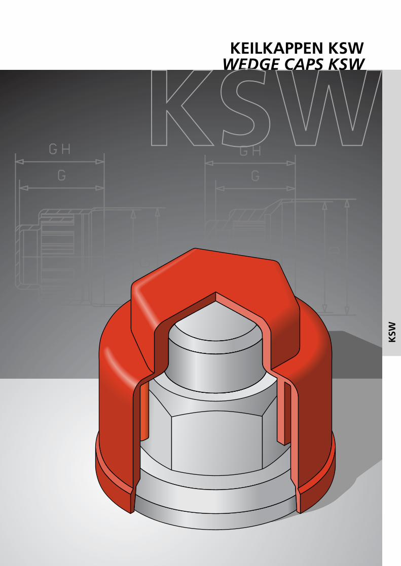
KEILKAPPEN KSWWEDGE CAPS KSW
KSW
KSW
48
KSW
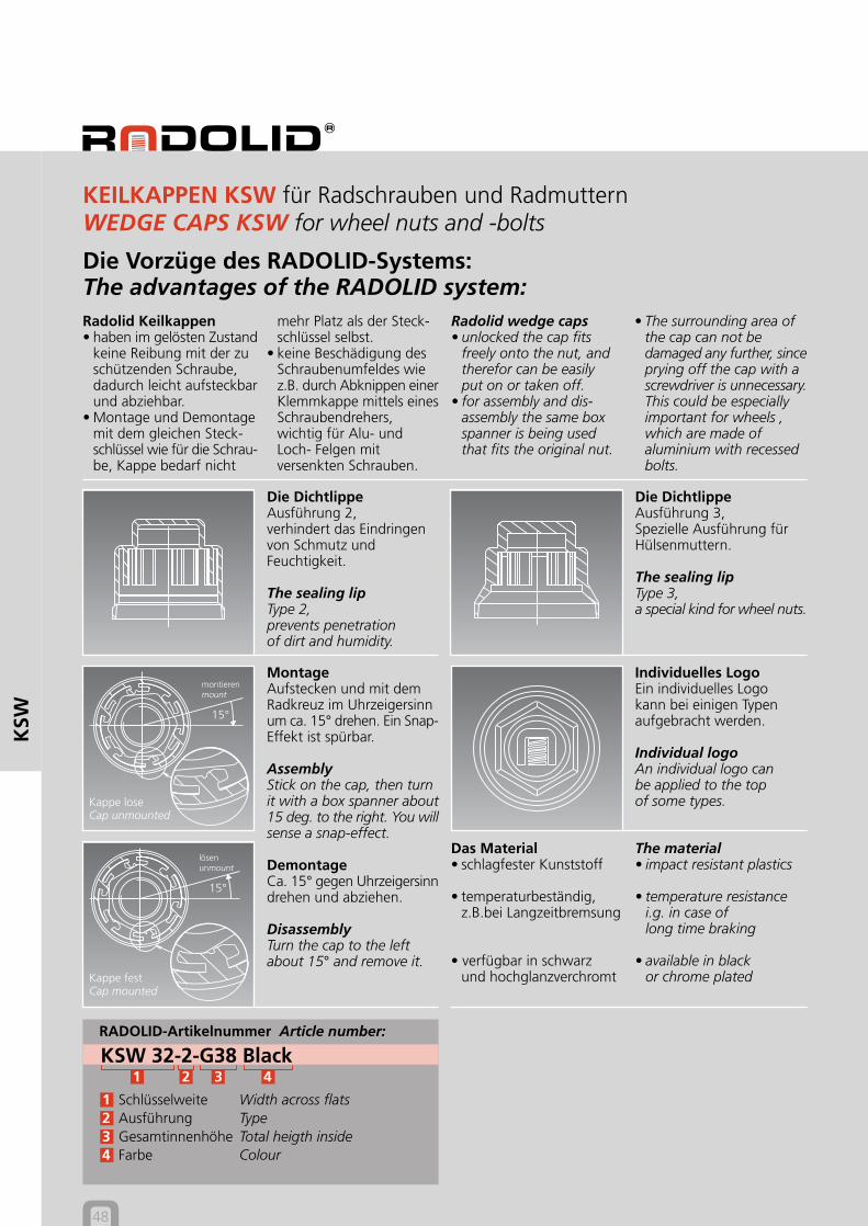
RADOLID-Artikelnummer Article number:
KSW 32-2-G38 Black1 2 3 4
1 Schlüsselweite Width across flats2 Ausführung Type3 Gesamtinnenhöhe Total heigth inside4 Farbe Colour
mehr Platz als der Steck-schlüssel selbst.
• keine Beschädigung desSchraubenumfeldes wiez.B. durch Abknippen einerKlemmkappe mittels einesSchraubendrehers,wichtig für Alu- undLoch- Felgen mitversenkten Schrauben.
• The surrounding area ofthe cap can not bedamaged any further, sinceprying off the cap with ascrewdriver is unnecessary.This could be especiallyimportant for wheels ,which are made ofaluminium with recessedbolts.
Die Vorzüge des RADOLID-Systems:The advantages of the RADOLID system:Radolid Keilkappen• haben im gelösten Zustand
keine Reibung mit der zuschützenden Schraube,dadurch leicht aufsteckbarund abziehbar.
• Montage und Demontagemit dem gleichen Steck-schlüssel wie für die Schrau-be, Kappe bedarf nicht
MontageAufstecken und mit demRadkreuz im Uhrzeigersinnum ca. 15° drehen. Ein Snap-Effekt ist spürbar.
AssemblyStick on the cap, then turnit with a box spanner about15 deg. to the right. You willsense a snap-effect.
DemontageCa. 15° gegen Uhrzeigersinndrehen und abziehen.
DisassemblyTurn the cap to the leftabout 15° and remove it.
KEILKAPPEN KSW für Radschrauben und RadmutternWEDGE CAPS KSW for wheel nuts and -bolts
Radolid wedge caps• unlocked the cap fits
freely onto the nut, andtherefor can be easilyput on or taken off.
• for assembly and dis-assembly the same boxspanner is being usedthat fits the original nut.
Die DichtlippeAusführung 2,verhindert das Eindringenvon Schmutz undFeuchtigkeit.
The sealing lipType 2,prevents penetrationof dirt and humidity.
Die DichtlippeAusführung 3,Spezielle Ausführung fürHülsenmuttern.
The sealing lipType 3,a special kind for wheel nuts.
Das Material• schlagfester Kunststoff
• temperaturbeständig,z.B.bei Langzeitbremsung
• verfügbar in schwarzund hochglanzverchromt
The material• impact resistant plastics
• temperature resistancei.g. in case oflong time braking
• available in blackor chrome plated
Individuelles LogoEin individuelles Logokann bei einigen Typenaufgebracht werden.
Individual logoAn individual logo canbe applied to the topof some types.
Kappe festCap mounted
Kappe loseCap unmounted
15°
montierenmount
15°
lösenunmount
Heightinside
Innen-höhe
Heightoutside
Außen-höhe
Comp.Ø
GesamtØ
InsideØ
InnenØ
Ausführung Type 2
KEILKAPPEN KSWWEDGE CAPS KSW
Ausführung Type 3
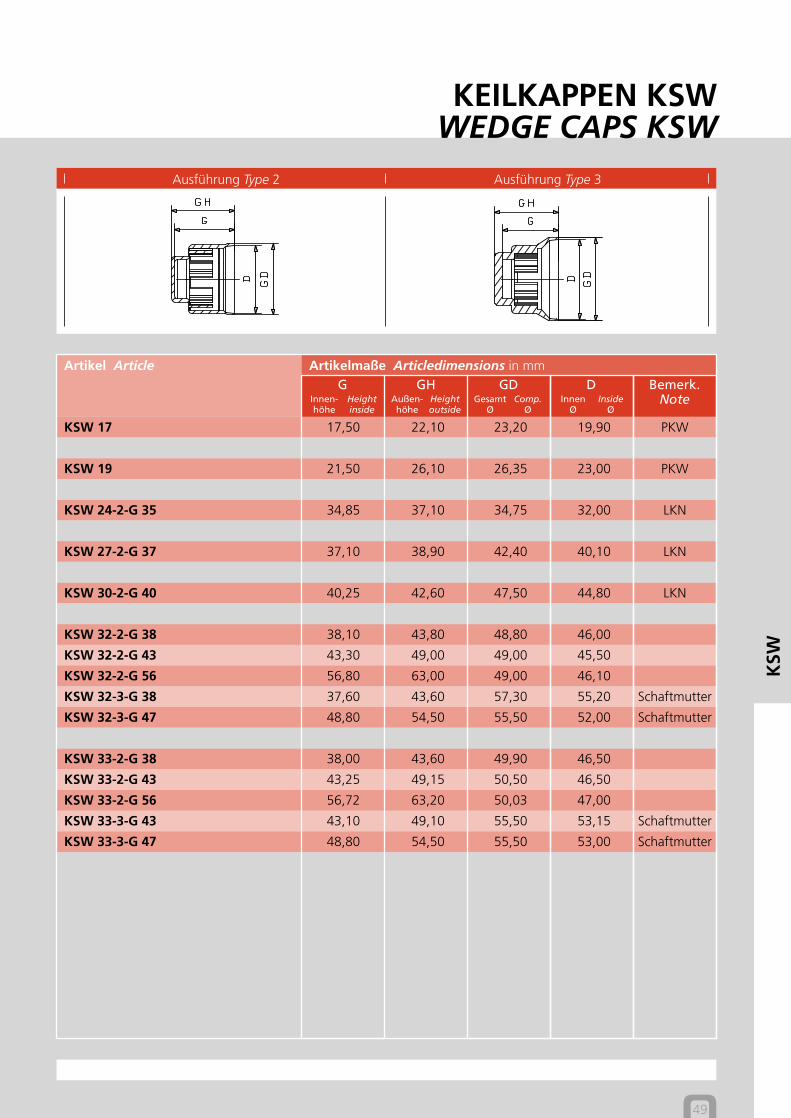
49
Artikelmaße Articledimensions in mmArtikel ArticleG GH GD D Bemerk.
Note
KSW
KSW 17 17,50 22,10 23,20 19,90 PKW
KSW 19 21,50 26,10 26,35 23,00 PKW
KSW 24-2-G 35 34,85 37,10 34,75 32,00 LKN
KSW 27-2-G 37 37,10 38,90 42,40 40,10 LKN
KSW 30-2-G 40 40,25 42,60 47,50 44,80 LKN
KSW 32-2-G 38 38,10 43,80 48,80 46,00
KSW 32-2-G 43 43,30 49,00 49,00 45,50
KSW 32-2-G 56 56,80 63,00 49,00 46,10
KSW 32-3-G 38 37,60 43,60 57,30 55,20 Schaftmutter
KSW 32-3-G 47 48,80 54,50 55,50 52,00 Schaftmutter
KSW 33-2-G 38 38,00 43,60 49,90 46,50
KSW 33-2-G 43 43,25 49,15 50,50 46,50
KSW 33-2-G 56 56,72 63,20 50,03 47,00
KSW 33-3-G 43 43,10 49,10 55,50 53,15 Schaftmutter
KSW 33-3-G 47 48,80 54,50 55,50 53,00 Schaftmutter
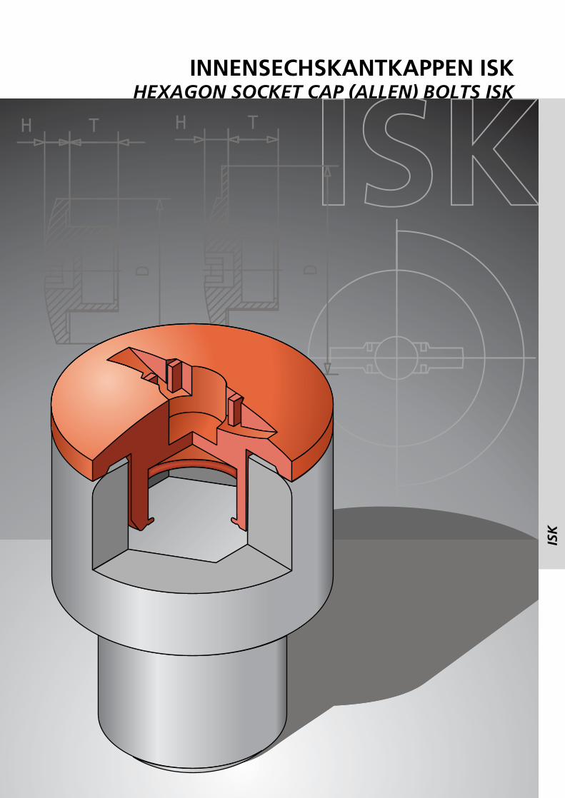
INNENSECHSKANTKAPPEN ISKHEXAGON SOCKET CAP (ALLEN) BOLTS ISK
ISK
ISK
52
ISK
ISK Kappefestfixed
30°
Arretier-KeileArretier blocks
ISK Kappeloseloose
Klemm-Keillocking block
RADOLID-Artikelnummer Article number:
ISK 8-1-T5 / D16 PA1 2 3 4 5
1 Schlüsselweite Width across flats2 Ausführung Type3 Einstecktiefe Press in deep4 Außendurchmesser Outside diameter5 Material Material
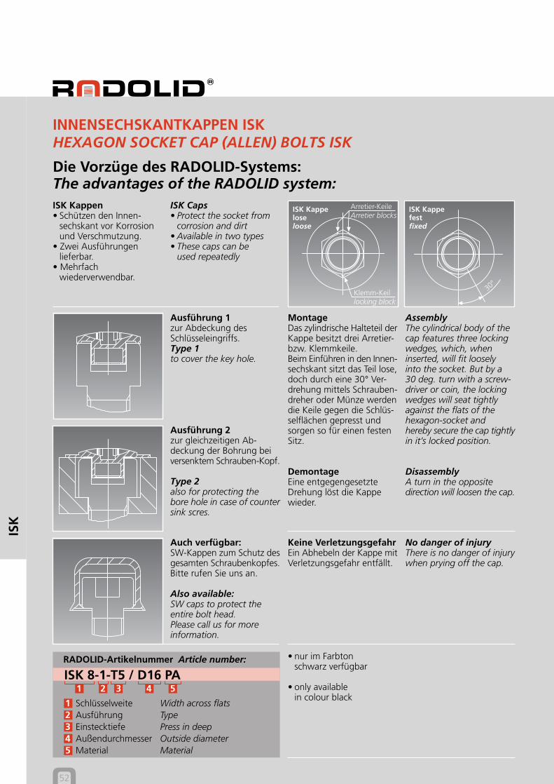
Die Vorzüge des RADOLID-Systems:The advantages of the RADOLID system:ISK Kappen• Schützen den Innen-
sechskant vor Korrosionund Verschmutzung.
• Zwei Ausführungenlieferbar.
• Mehrfachwiederverwendbar.
INNENSECHSKANTKAPPEN ISKHEXAGON SOCKET CAP (ALLEN) BOLTS ISK
Ausführung 1zur Abdeckung desSchlüsseleingriffs.Type 1to cover the key hole.
AssemblyThe cylindrical body of thecap features three lockingwedges, which, wheninserted, will fit looselyinto the socket. But by a30 deg. turn with a screw-driver or coin, the lockingwedges will seat tightlyagainst the flats of thehexagon-socket andhereby secure the cap tightlyin it’s locked position.
DisassemblyA turn in the oppositedirection will loosen the cap.
ISK Caps• Protect the socket from
corrosion and dirt• Available in two types• These caps can be
used repeatedly
MontageDas zylindrische Halteteil derKappe besitzt drei Arretier-bzw. Klemmkeile.Beim Einführen in den Innen-sechskant sitzt das Teil lose,doch durch eine 30° Ver-drehung mittels Schrauben-dreher oder Münze werdendie Keile gegen die Schlüs-selflächen gepresst undsorgen so für einen festenSitz.
DemontageEine entgegengesetzteDrehung löst die Kappewieder.
Ausführung 2zur gleichzeitigen Ab-deckung der Bohrung beiversenktem Schrauben-Kopf.
Type 2also for protecting thebore hole in case of countersink scres.
Auch verfügbar:SW-Kappen zum Schutz desgesamten Schraubenkopfes.Bitte rufen Sie uns an.
Also available:SW caps to protect theentire bolt head.Please call us for moreinformation.
• nur im Farbtonschwarz verfügbar
• only availablein colour black
No danger of injuryThere is no danger of injurywhen prying off the cap.
Keine VerletzungsgefahrEin Abhebeln der Kappe mitVerletzungsgefahr entfällt.
INNENSECHSKANTKAPPEN ISKHEXAGON SOCKET CAP (ALLEN) BOLTS ISK
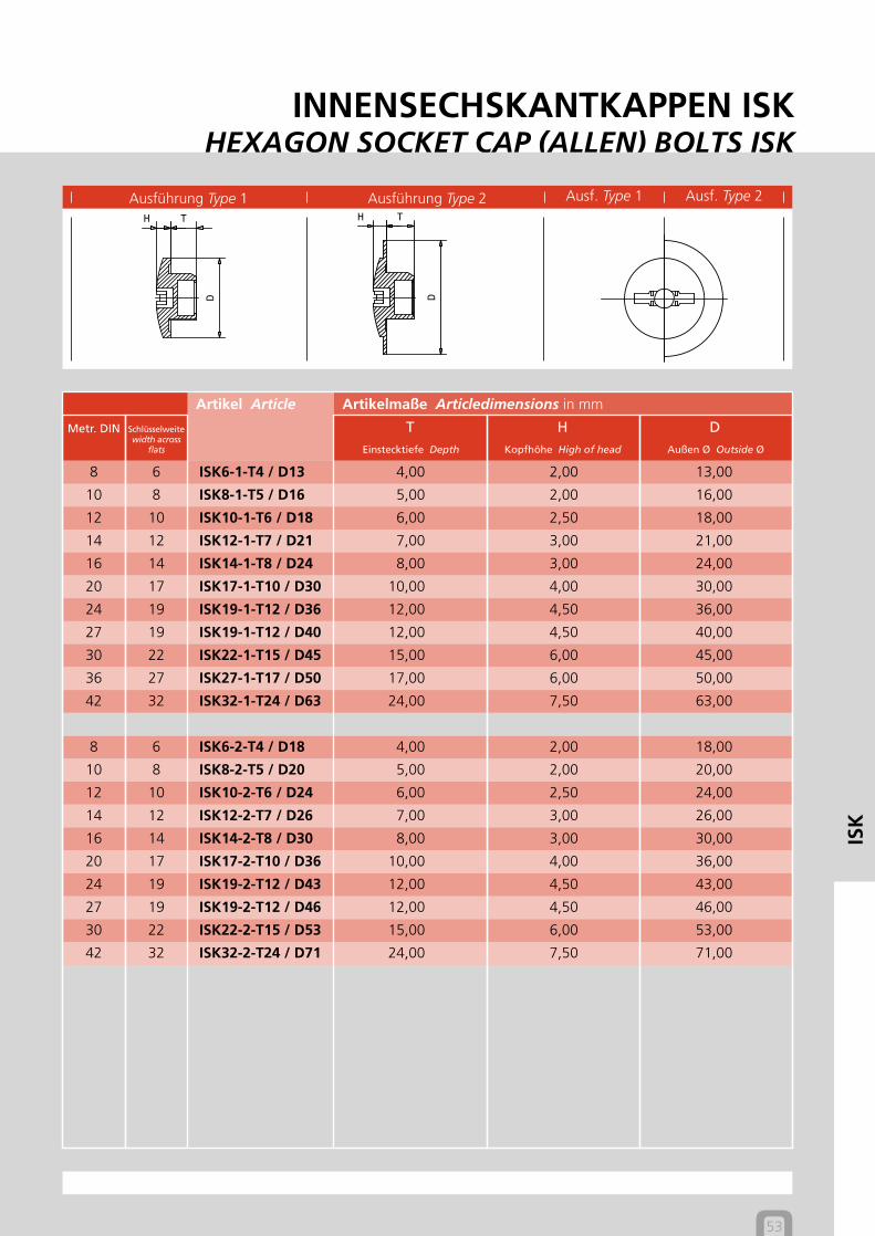
Außen Ø Outside Ø
Ausführung Type 1 Ausführung Type 2 Ausf. Type 1 Ausf. Type 2
Einstecktiefe Depth Kopfhöhe High of head
53
Artikelmaße Articledimensions in mm
Schlüsselweitewidth across
flats
Artikel Article
TMetr. DIN H D
ISK
8 6 ISK6-1-T4 / D13 4,00 2,00 13,00
10 8 ISK8-1-T5 / D16 5,00 2,00 16,00
12 10 ISK10-1-T6 / D18 6,00 2,50 18,00
14 12 ISK12-1-T7 / D21 7,00 3,00 21,00
16 14 ISK14-1-T8 / D24 8,00 3,00 24,00
20 17 ISK17-1-T10 / D30 10,00 4,00 30,00
24 19 ISK19-1-T12 / D36 12,00 4,50 36,00
27 19 ISK19-1-T12 / D40 12,00 4,50 40,00
30 22 ISK22-1-T15 / D45 15,00 6,00 45,00
36 27 ISK27-1-T17 / D50 17,00 6,00 50,00
42 32 ISK32-1-T24 / D63 24,00 7,50 63,00
8 6 ISK6-2-T4 / D18 4,00 2,00 18,00
10 8 ISK8-2-T5 / D20 5,00 2,00 20,00
12 10 ISK10-2-T6 / D24 6,00 2,50 24,00
14 12 ISK12-2-T7 / D26 7,00 3,00 26,00
16 14 ISK14-2-T8 / D30 8,00 3,00 30,00
20 17 ISK17-2-T10 / D36 10,00 4,00 36,00
24 19 ISK19-2-T12 / D43 12,00 4,50 43,00
27 19 ISK19-2-T12 / D46 12,00 4,50 46,00
30 22 ISK22-2-T15 / D53 15,00 6,00 53,00
42 32 ISK32-2-T24 / D71 24,00 7,50 71,00
KOMBINATIONSKAPPEN COM / SX KAPPENCOMBI CAPS COM / SX CAPS
54
CO
M/S
X
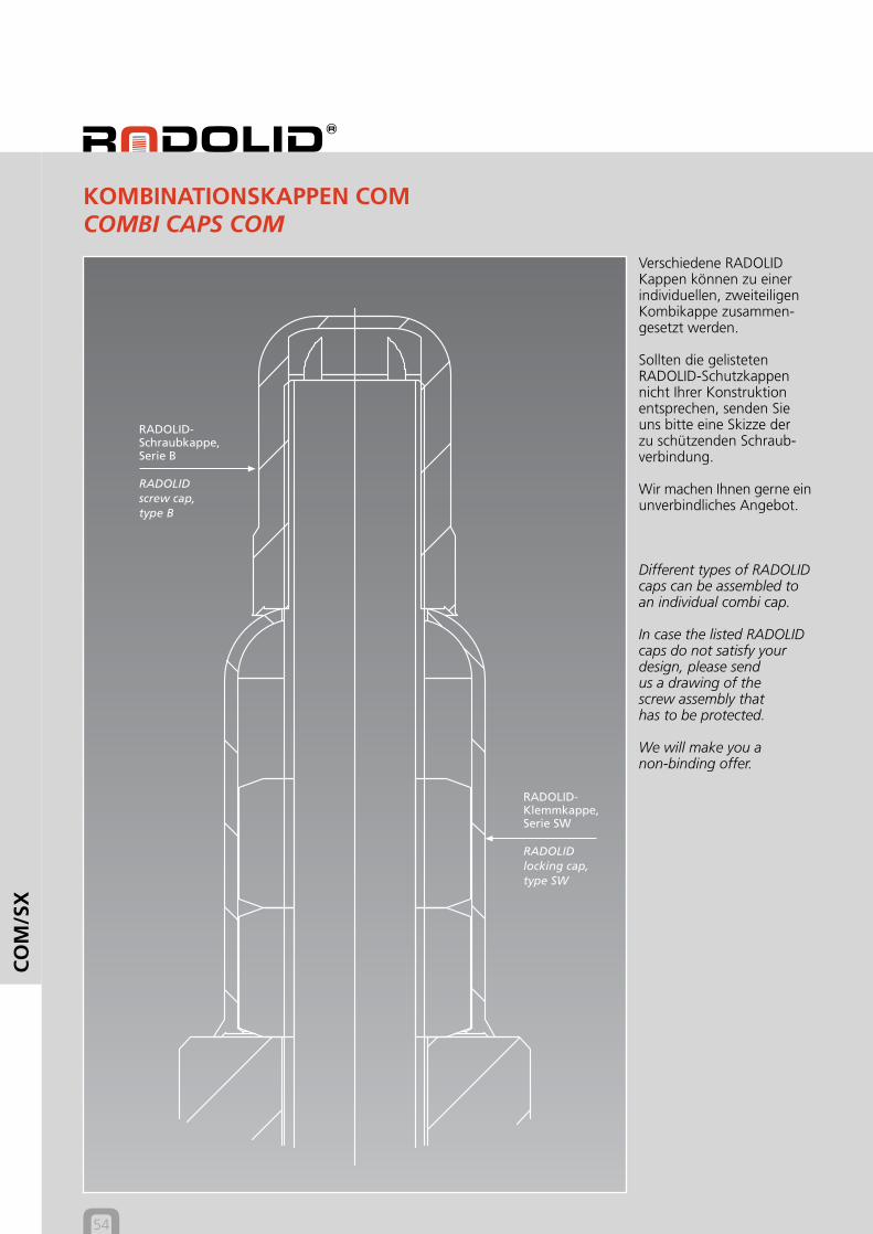
Verschiedene RADOLIDKappen können zu einerindividuellen, zweiteiligenKombikappe zusammen-gesetzt werden.
Sollten die gelistetenRADOLID-Schutzkappennicht Ihrer Konstruktionentsprechen, senden Sieuns bitte eine Skizze derzu schützenden Schraub-verbindung.
Wir machen Ihnen gerne einunverbindliches Angebot.
Different types of RADOLIDcaps can be assembled toan individual combi cap.
In case the listed RADOLIDcaps do not satisfy yourdesign, please sendus a drawing of thescrew assembly thathas to be protected.
We will make you anon-binding offer.
KOMBINATIONSKAPPEN COMCOMBI CAPS COM
RADOLID-Schraubkappe,Serie B
RADOLIDscrew cap,type B
RADOLID-Klemmkappe,Serie SW
RADOLIDlocking cap,type SW
KOMBINATIONSKAPPEN COM / SX KAPPENCOMBI CAPS COM / SX CAPS
55
CO
M/S
X
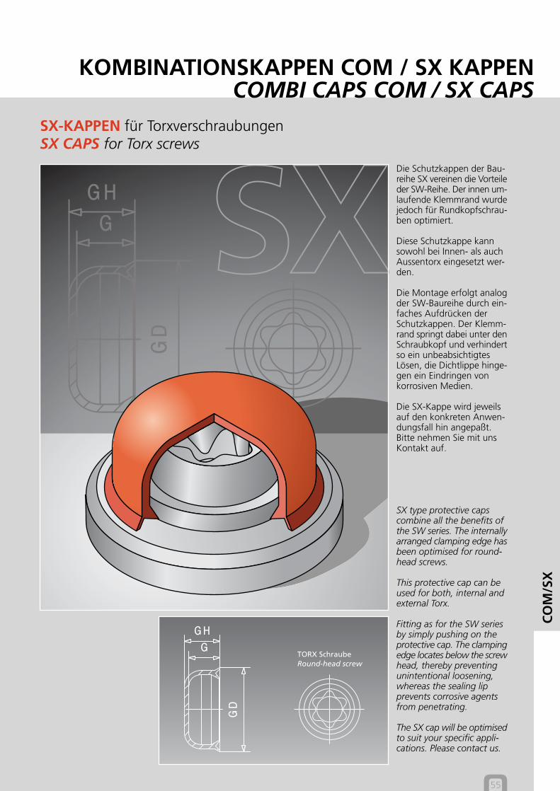
SX-KAPPEN für TorxverschraubungenSX CAPS for Torx screws
Die Schutzkappen der Bau-reihe SX vereinen die Vorteileder SW-Reihe. Der innen um-laufende Klemmrand wurdejedoch für Rundkopfschrau-ben optimiert.
Diese Schutzkappe kannsowohl bei Innen- als auchAussentorx eingesetzt wer-den.
Die Montage erfolgt analogder SW-Baureihe durch ein-faches Aufdrücken derSchutzkappen. Der Klemm-rand springt dabei unter denSchraubkopf und verhindertso ein unbeabsichtigtesLösen, die Dichtlippe hinge-gen ein Eindringen vonkorrosiven Medien.
Die SX-Kappe wird jeweilsauf den konkreten Anwen-dungsfall hin angepaßt.Bitte nehmen Sie mit unsKontakt auf.
SX type protective capscombine all the benefits ofthe SW series. The internallyarranged clamping edge hasbeen optimised for round-head screws.
This protective cap can beused for both, internal andexternal Torx.
Fitting as for the SW seriesby simply pushing on theprotective cap. The clampingedge locates below the screwhead, thereby preventingunintentional loosening,whereas the sealing lipprevents corrosive agentsfrom penetrating.
The SX cap will be optimisedto suit your specific appli-cations. Please contact us.
TORX SchraubeRound-head screw
56
ZUB
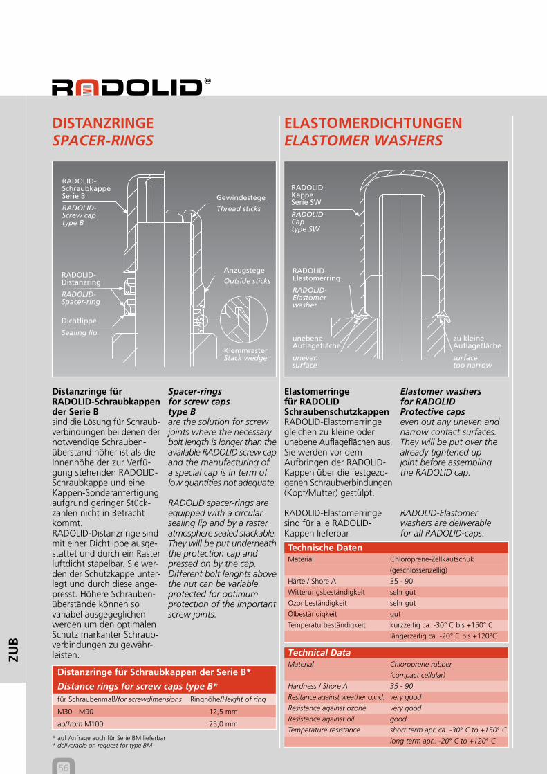
Distanzringe fürRADOLID-Schraubkappender Serie Bsind die Lösung für Schraub-verbindungen bei denen dernotwendige Schrauben-überstand höher ist als dieInnenhöhe der zur Verfü-gung stehenden RADOLID-Schraubkappe und eineKappen-Sonderanfertigungaufgrund geringer Stück-zahlen nicht in Betrachtkommt.RADOLID-Distanzringe sindmit einer Dichtlippe ausge-stattet und durch ein Rasterluftdicht stapelbar. Sie wer-den der Schutzkappe unter-legt und durch diese ange-presst. Höhere Schrauben-überstände können sovariabel ausgegeglichenwerden um den optimalenSchutz markanter Schraub-verbindungen zu gewähr-leisten.
DISTANZRINGESPACER-RINGS
ELASTOMERDICHTUNGENELASTOMER WASHERS
Spacer-ringsfor screw capstype Bare the solution for screwjoints where the necessarybolt length is longer than theavailable RADOLID screw capand the manufacturing ofa special cap is in term oflow quantities not adequate.
RADOLID spacer-rings areequipped with a circularsealing lip and by a rasteratmosphere sealed stackable.They will be put underneaththe protection cap andpressed on by the cap.Different bolt lenghts abovethe nut can be variableprotected for optimumprotection of the importantscrew joints.
Elastomerringefür RADOLIDSchraubenschutzkappenRADOLID-Elastomerringegleichen zu kleine oderunebene Auflageflächen aus.Sie werden vor demAufbringen der RADOLID-Kappen über die festgezo-genen Schraubverbindungen(Kopf/Mutter) gestülpt.
RADOLID-Elastomerringesind für alle RADOLID-Kappen lieferbar
Distanzringe für Schraubkappen der Serie B*
Distance rings for screw caps type B*für Schraubenmaß/for screwdimensions Ringhöhe/Height of ring
M30 - M90 12,5 mm
ab/from M100 25,0 mm
* auf Anfrage auch für Serie BM lieferbar* deliverable on request for type BM
RADOLID-SchraubkappeSerie B
RADOLID-Screw captype B
RADOLID-Distanzring
RADOLID-Spacer-ring
Dichtlippe
Sealing lip
Gewindestege
Thread sticks
Anzugstege
Outside sticks
KlemmrasterStack wedge
RADOLID-KappeSerie SW
RADOLID-Captype SW
RADOLID-Elastomerring
RADOLID-Elastomerwasher
unevensurface
unebeneAuflagefläche
surfacetoo narrow
zu kleineAuflagefläche
Elastomer washersfor RADOLIDProtective capseven out any uneven andnarrow contact surfaces.They will be put over thealready tightened upjoint before assemblingthe RADOLID cap.
RADOLID-Elastomerwashers are deliverablefor all RADOLID-caps.
Technische DatenMaterial Chloroprene-Zellkautschuk
(geschlossenzellig)
Härte / Shore A 35 - 90
Witterungsbeständigkeit sehr gut
Ozonbeständigkeit sehr gut
Ölbeständigkeit gut
Temperaturbeständigkeit kurzzeitig ca. -30° C bis +150° Clängerzeitig ca. -20° C bis +120°C
Technical DataMaterial Chloroprene rubber
(compact cellular)
Hardness / Shore A 35 - 90
Resitance against weather cond. very good
Resistance against ozone very good
Resistance against oil good
Temperature resistance short term apr. ca. -30° C to +150° Clong term apr.. -20° C to +120° C
ZUBEHÖRACCESSORIES
57
StahlSteel
SW-KappeSW cap
VCI
ZUB
EVOPRENERINGEEVOPRENE SEALS
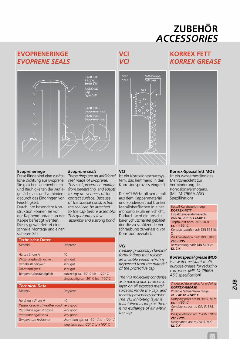
EvopreneringeDiese Ringe sind eine zusätz-liche Dichtung aus Evoprene.Sie gleichen Unebenheitenund Rauhigkeiten der Aufla-gefläche aus und verhinderndadurch das Eindringen vonFeuchtigkeit.Durch ihre besondere Kon-struktion können sie vorder Kappenmontage an derKappe befestigt werden.Dieses gewährleistet eineschnelle Montage und einensicheren Sitz.
Evoprene sealsThese rings are an additionalseal made of Evoprene.This seal prevents humidityfrom penetrating, and adaptsto any unevenness of thecontact surface. Becauseof the special constructionthe seal can be attachedto the cap before assembly.This guarantees fast assembly and a strong bond.
VCIVCI
KORREX FETTKORREX GREASE
VCIist ein Korrosionsschutzsys-tem, das hemmend in denKorrosionsprozess eingreift.
Der VCI-Wirkstoff verdampftaus dem Kappenmaterialund kondensiert auf blankenMetalloberflächen in einermonomolekularen Schicht.Dadurch wird ein unsicht-barer Schutzmantel gebildet,der die zu schützende Ver-schraubung zuverlässig vorKorrosion bewahrt.
VCIcontains proprietary chemicalformulations that releasean invisible vapor, which isdispensed from the materialof the protective cap.
The VCI molecules condenseas a microscopic protectivelayer on all exposed metalsurfaces inside the cap, andthereby preventing corrosion.The VCI inhibiting layer ismaintained as long as thereis no exchange of air withinthe cap.
RADOLID-KappeSerie SW
RADOLID-Captype SW
RADOLID-Evoprenering
RADOLID-Evoprene seal
Korrex-Spezialfett MOSist ein wasserbeständigesMehrzweckfett zurVerminderung desKorrosionsvermögens.(MIL-M-7966A ASG-Spezifikation)
Bestell-Kurzbezeichnung:KORREX-FETTEinsatztemperaturbereich:von ca. -50° bis +140° CTropfpunkt nach DIN 51801:ca. + 190° CKonsistenzstufe nach DIN 51818:2Walkpenetration nach DIN 51805:265 / 295Bezeichnung nach DIN 51802:KL 2 K
Korrex special grease MOSis a water-resistant multi-purpose grease for reducingcorrosion. (MIL M-7966AASG specification)
Shortened designation for ordering:KORREX-GREASEPossible temperature range:ca. -50° to +140° CDropping point acc.to DIN 51801:ca. + 190° CConsistency acc. to DIN 51818:2Walkpenetration acc. to DIN 51805:265 / 295Designation acc.to DIN 51802:KL 2 K
Technische DatenMaterial Evoprene
Härte / Shore A 40
Witterungsbeständigkeit sehr gut
Ozonbeständigkeit sehr gut
Ölbeständigkeit sehr gut
Temperaturbeständigkeit kurzzeitig ca. -30° C bis +120° Clängerzeitig ca. -20° C bis +100°C
Technical DataMaterial Evoprene
Hardness / Shore A 40
Resistance against weather cond. very good
Resistance against ozone very good
Resistance against oil very good
Temperature resistance short term apr. ca. -30° C to +120° Clong term apr.. -20° C to +100° C
WERKSTOFFEMATERIALS
MA
T
Kunststoff-bezeichnung
Description ofplastic
DichteDensity
G/cm3
HärteHardness
Durchgangs-spannung
Breakdownvoltage
nach/according to DIN
KV/ mmkurzzeitigshort-time
dauerndconstancy
TemperaturbeständigkeitTemperature resistance
Bemerkung
Note
Standard-Werkstoff Standard material
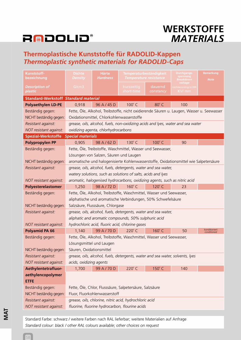
Polyaethylen LD-PE 0,918 96 A / 45 D 100˚ C 80˚ C 100
Beständig gegen: Fette, Öle, Alkohol, Treibstoffe, nicht oxidierende Säuren u. Laugen, Wasser u. Seewasser
NICHT beständig gegen: Oxidationsmittel, Chlorkohlenwasserstoffe
Resistant against: grease, oils, alcohol, fuels, non-oxidizing acids and lyes, water and sea water
NOT resistant against: oxidizing agenta, chlorhydrocarbons
Spezial-Werkstoffe Special materials
Polypropylen PP 0,905 98 A / 62 D 130˚ C 100˚ C 90
Beständig gegen: Fette, Öle, Treibstoffe, Waschmittel, Wasser und Seewasser,
Lösungen von Salzen, Säuren und Laugen
NICHT beständig gegen: aromatische und halogenisierte Kohlenwasserstoffe, Oxidationsmittel wie Salpetersäure
Resistant against: grease, oils, alcohol, fuels, detergents, water and sea water,
watery solutions, such as solutions of salts, acids and lyes
NOT resistant against: aromatic, halogenised hydrocarbons, oxidizing agents, such as nitric acid
Polyesterelastomer 1,250 98 A / 72 D 160˚ C 120˚ C 23
Beständig gegen: Fette, Öle, Alkohol, Treibstoffe, Waschmittel, Wasser und Seewasser,
aliphatische und aromatische Verbindungen, 50% Schwefelsäure
NICHT beständig gegen: Salzsäure, Flusssäure, Chlorgase
Resistant against: grease, oils, alcohol, fuels, detergents, water and sea water,
aliphatic and aromatic compounds, 50% sulphuric acid
NOT resistant against: hydrochloric acid, fluoric acid, chlorine gases
Polyamid PA 66 1,140 99 A / 70 D 220˚ C 160˚ C 50
Beständig gegen: Fette, Öle, Alkohol, Treibstoffe, Waschmittel, Wasser und Seewasser,
Lösungsmittel und Laugen
NICHT beständig gegen: Säuren, Oxidationsmittel
Resistant against: grease, oils, alcohol, fuels, detergents, water and sea water, solvents, lyes
NOT resistant against: acids, oxidizing agents
Aethylentetrafluor- 1,700 99 A / 70 D 220˚ C 150˚ C 140
aethylencopolymer
ETFE
Beständig gegen: Fette, Öle, Chlor, Flusssäure, Salpetersäure, Salzsäure
NICHT beständig gegen: Fluor, Fluorkohlenwasserstoff
Resistant against: grease, oils, chlorine, nitric acid, hydrochloric acid
NOT resistant against: fluorine, fluorine hydrocarbon, flourine acids
Thermoplastische Kunststoffe für RADOLID-KappenThermoplastic synthetic materials for RADOLID-Caps
Standard Farbe: schwarz / weitere Farben nach RAL lieferbar; weitere Materialien auf Anfrage
Standard colour: black / other RAL colours available; other choices on request
konditioniertconditioned
58
MANSCHETTENGASKETS
59
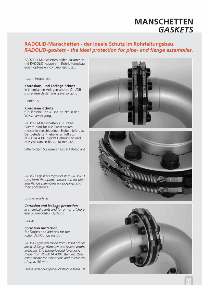
RADOLID-Manschetten - der ideale Schutz im Rohrleitungsbau.RADOLID-gaskets - the ideal protection for pipe- and flange assemblies.
RADOLID-Manschetten bilden zusammenmit RADOLID-Kappen im Rohrleitungsbaueinen optimalen Korrosionsschutz...
...zum Beispiel als
Korrosions- und Leckage-Schutzin chemischen Anlagen und im On-/Off-shore-Bereich der Energieversorgung.
...oder als
Korrosions-Schutzfür Flansche und Ausbaustücke in derWasserversorgung.
RADOLID-Manschetten aus EPDM-Gummi sind für alle Flanschdurch-messer in verschiedenen Breiten lieferbar.Der gefederte Knebelverschluß ausNIROSTA 4301 gleicht Dehnungen undMasstoleranzen bis zu 30 mm aus.
Bitte fordern Sie unseren Extra-Katalog an!
RADOLID-gaskets together with RADOLIDcaps form the optimal protection for pipeand flange assemblies for pipelines andtheir accessories...
...for example as
Corrosion and leakage protectionin chemical plants and for on- or offshoreenergy distribution systems.
...or as
Corrosion protectionfor flanges and add-ons for thewater-distribution sector.
RADOLID-gaskets made from EPDM rubberare in all flange-diameters and several widthsavailable. The spring-loaded lever-locksmade from NIROSTA 4301 stainless steelcompensate for expansions and tolerancesof up to 30 mm.
Please order our special catalogue from us!
Radolid Thiel GmbH
Lösenbacher Landstraße 166D-58509 LüdenscheidTelefon +49 (0) 23 51/ 97 94 94Telefax +49 (0) 23 51/ 97 94 90E-mail [email protected] www.radolid.de