Embed Size (px)
Citation preview
1
1
The ITER Neutral Beam system: status of the project and review of the main technological issues
presented by
V. Antoni
Consorzio RFX, Euratom-ENEA Association, Padova, Italy
2
2
M. Bigi, A. De Lorenzi, D.Marcuzzi, A. Masiello, V. Toigo, P.Zaccaria,P.Agostinetti, G. Anaclerio, S. Dal Bello, M. Dalla Palma, E.Gaio, L. Grando, F. Milani, R. Nocentini, L. Novello, S. Peruzzo, N. Pilan, N. Pomaro, R. Piovan, F.Sattin, G. Serianni, M. Spolaore, M. Valisa, B. Zaniol, L. Zanotto, G.RostagniConsorzio RFX, Padova, ItalyS. Sandri, M. PillonENEA, Frascati, ItalyM. Cavenago, P. SpolaoreINFN, Padova, ItalyR. Hemsworth, D. Boilson, J.J. Cordier, B. De Esch, L. Svensson,CEA,Cadarache, FranceM. Liniers, A. López-Fraguas, J. Alonso,CIEMAT, Madrid, SpainA.Antipenkov, , M.Dremel, C.Day,FZK, Karlsruhe, GermanyE. Speth,H.D.Falter, U. Fantz, P. Franzen, B.Heinemann, W. Kraus, C. Martens, R.Riedl,IPP, Garching, GermanyT. T. Jones, B Chuilon , S. J. Cox, A. Emmanoulidis, M. Gilber M Kovari, Cs Jones G. Lawrence, M.J. Loughlin, D. Martin, J Milnes, E. Surrey, Y. Xue , C. Waldon, M J WatsonUKAEA, Culham, United KingdomT. Bonicelli, I. Benfatto, P. Barabaschi, P.L. Mondino,EFDA,GarchingA.TangaITER Team
co-authors
3
3
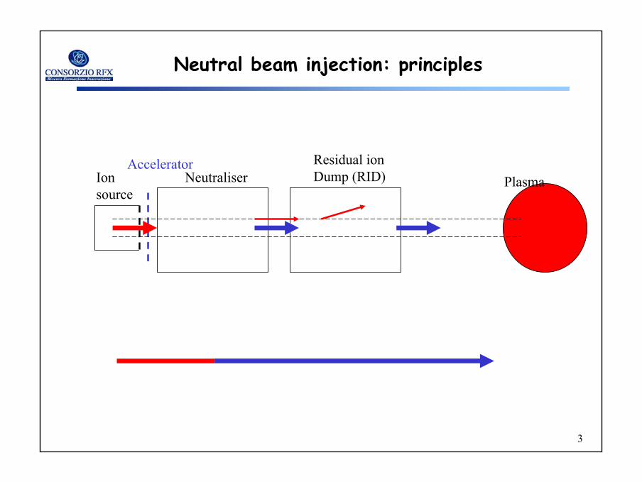
Neutral beam injection: principles
Ion source
NeutraliserResidual ion Dump (RID)
AcceleratorPlasma
4
4
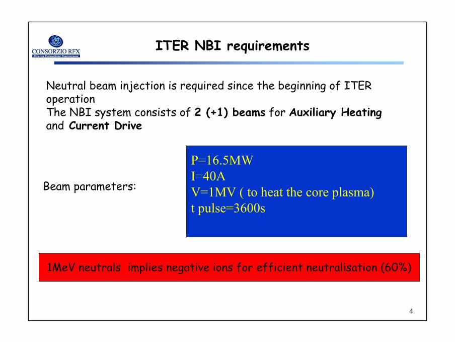
ITER NBI requirements
Neutral beam injection is required since the beginning of ITER operationThe NBI system consists of 2 (+1) beams for Auxiliary Heating and Current Drive
P=16.5MWI=40AV=1MV ( to heat the core plasma)t pulse=3600s
Beam parameters:
1MeV neutrals implies negative ions for efficient neutralisation (60%)
5
5
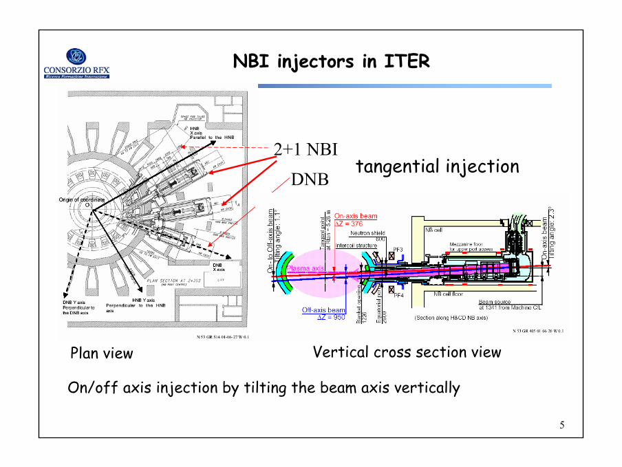
NBI injectors in ITER
DNB
2+1 NBItangential injection
On/off axis injection by tilting the beam axis vertically
Plan view Vertical cross section view
6
6
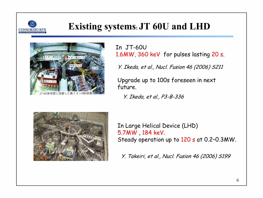
Existing systems: JT 60U and LHD
In JT-60U 1.6MW, 360 keV for pulses lasting 20 s.
In Large Helical Device (LHD) 5.7MW , 184 keV. Steady operation up to 120 s at 0.2–0.3MW.
Y. Takeiri, et al., Nucl. Fusion 46 (2006) S199
Y. Ikeda, et al., Nucl. Fusion 46 (2006) S211
Upgrade up to 100s foreseen in next future.
Y. Ikeda, et al., P3-B-336
7
7
Project revision: EU activities
Since 2003 an extensive activity promoted and co-ordinated by EFDA and carried out by six EU Associations (CEA, CIEMAT, FZK, IPP, ENEA-RFX and UKAEA) has been performed in Europe aimed to:
a) revise and update the NBI design for ITER [1]
b) bring the design of the alternative concepts for ion source and accelerator to the same level of detail of the reference design
c) adapt the design to a generic Test Facility.
[1] “ITER Technical Basis”, edited by IAEA, Vienna 2002
8
8
The NBI sub-systems
The NBI system can be separated in 4 subsystems:
a) The Injector
b) The Power Supply and Voltage Distribution System
c) The Control and Data Acquisition System
d) The Auxiliary System.
9
9
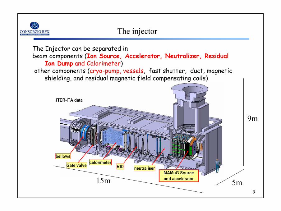
The Injector can be separated in beam components (Ion Source, Accelerator, Neutralizer, Residual
Ion Dump and Calorimeter) other components (cryo-pump, vessels, fast shutter, duct, magnetic
shielding, and residual magnetic field compensating coils)
The injector
15m 5m
9m
10
10
Beam formation
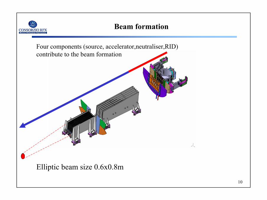
Four components (source, accelerator,neutraliser,RID) contribute to the beam formation
Elliptic beam size 0.6x0.8m
11
11
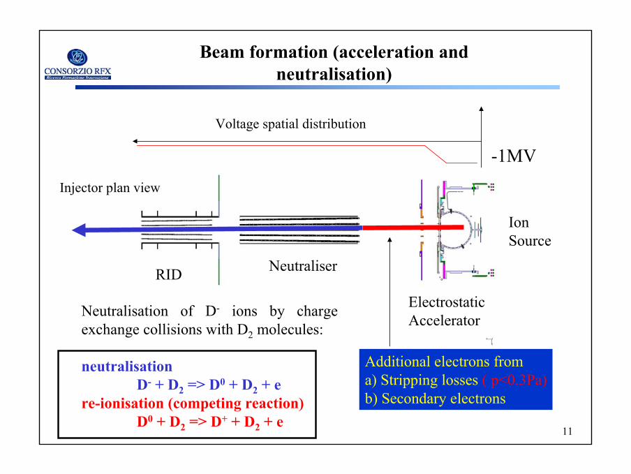
Beam formation (acceleration and neutralisation)
RID Neutraliser
ElectrostaticAccelerator
IonSource
Additional electrons from a) Stripping losses ( p<0.3Pa)b) Secondary electrons
-1MV
Neutralisation of D- ions by chargeexchange collisions with D2 molecules:
neutralisationD- + D2 => D0 + D2 + e
re-ionisation (competing reaction)D0 + D2 => D+ + D2 + e
Injector plan view
Voltage spatial distribution
12
12
POWER SUPPLY
BEAM SOURCE
BEAM LINE
TRANSMISSION LINE
POWER SUPPLY
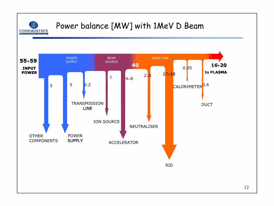
0.05
2÷4
INPUTPOWER
4÷81
17÷20to PLASMA
55÷59
5
40
NEUTRALISER
CALORIMETER
RID
ION SOURCE
DUCT
0.6
POWER SUPPLY
BEAM BEAM LINE
OTHERCOMPONENTS
LINE
SUPPLY
0.05
2÷5
ACCELERATOR
INPUTPOWER
4÷81
16÷20to PLASMA
55÷59
5
40
0.25
SOURCE
17÷1817÷18
Power balance [MW] with 1MeV D Beam
13
13
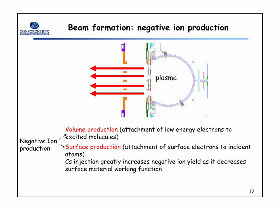
Beam formation: negative ion production
Surface production (attachment of surface electrons to incident atoms)Cs injection greatly increases negative ion yield as it decreases surface material working function
Negative Ion production
Volume production (attachment of low energy electrons to excited molecules)
plasma
14
14
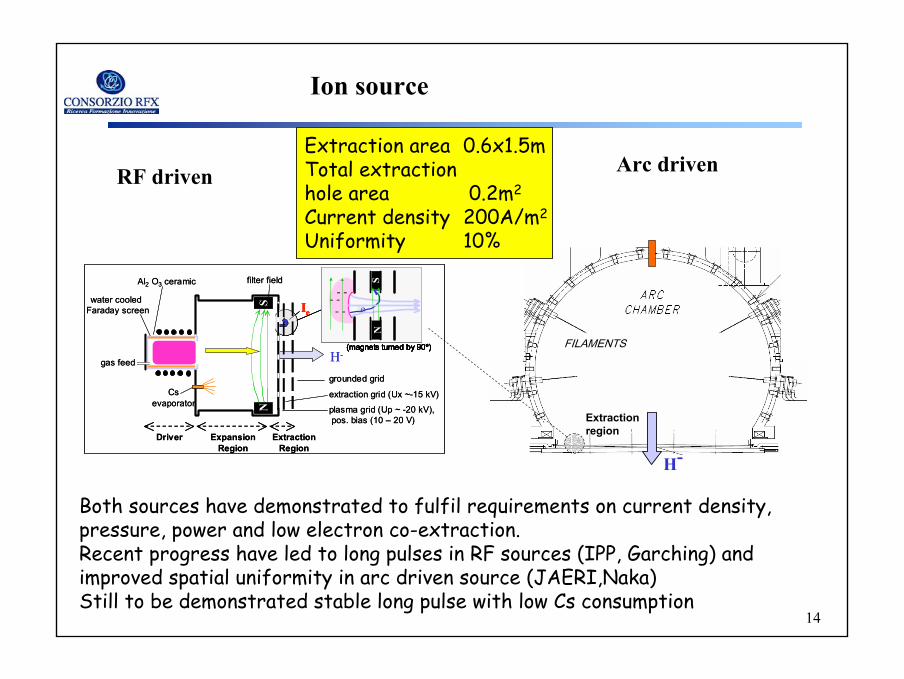
Ion source
H-
Ie- -
NS
e- -
- -
(magnets turned by 90º)
plasma grid (Up ~ -20 kV),pos. bias (10 – 20 V)
grounded grid
extraction grid (Ux ~-15 kV)Csevaporator
water cooled Faraday screen
Al2 O3 ceramic
gas feed
filter field
NS
Driver ExpansionRegion
ExtractionRegion
H-
Ie- -
NS
e- -
- -
(magnets turned by 90º)
Ie- -
NS
e- -
- -
(magnets turned by 90º)
- -
NS
e- -
- -
(magnets turned by 90º)
- -
NS
e- -
- -
(magnets turned by 90º)
- -
NS
e- -
- -
(magnets turned by 90º)
plasma grid (Up ~ -20 kV),pos. bias (10 – 20 V)
grounded grid
extraction grid (Ux ~-15 kV)Csevaporator
water cooled Faraday screen
Al2 O3 ceramic
gas feed
filter field
NSS
Driver ExpansionRegion
ExtractionRegion
FILAMENTS
H-
RF driven Arc driven
Extractionregion
Both sources have demonstrated to fulfil requirements on current density, pressure, power and low electron co-extraction. Recent progress have led to long pulses in RF sources (IPP, Garching) and improved spatial uniformity in arc driven source (JAERI,Naka)Still to be demonstrated stable long pulse with low Cs consumption
Extraction area 0.6x1.5mTotal extraction hole area 0.2m2
Current density 200A/m2
Uniformity 10%
15
15
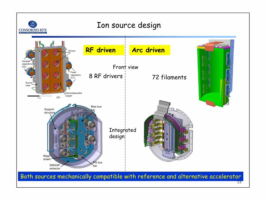
Ion source design
Support structure
SINGAP extractor
Magn shield
PG bus bar
Bias bus bar
Variable capacitors(C2)
Drivers
Source case
Fixed capacitors(C1)
Electrodepositedcopper(b)1 m
RF driven Arc driven
Front view
Both sources mechanically compatible with reference and alternative accelerator
8 RF drivers 72 filaments
Integrateddesign
16
16
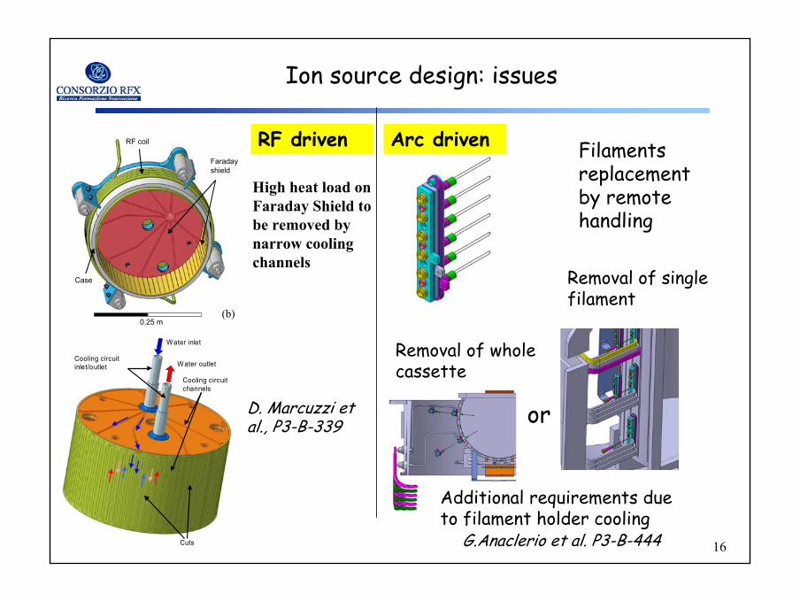
RF coil
Case
Faraday shield
(b)0.25 m
Cooling circuit inlet/outlet
Cooling circuit channels
Cuts
Water inlet
Water outlet
High heat load on Faraday Shield tobe removed bynarrow coolingchannels
Removal of wholecassette
Removal of single filament
G.Anaclerio et al. P3-B-444
Ion source design: issues
RF driven Arc driven
D. Marcuzzi et al., P3-B-339 or
Additional requirements due to filament holder cooling
Filamentsreplacementby remote handling
17
17
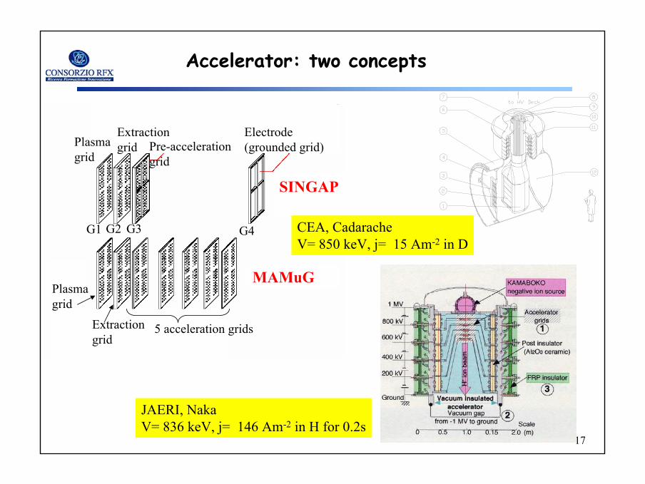
Accelerator: two concepts
SINGAP
MAMuG
-990 kVPlasma grid
Extraction grid Pre-acceleration
grid
Electrode (grounded grid)
G1 G2 G3 G4
Plasma grid
Extraction grid
5 acceleration grids
JAERI, NakaV= 836 keV, j= 146 Am-2 in H for 0.2s
CEA, CadaracheV= 850 keV, j= 15 Am-2 in D
18
18
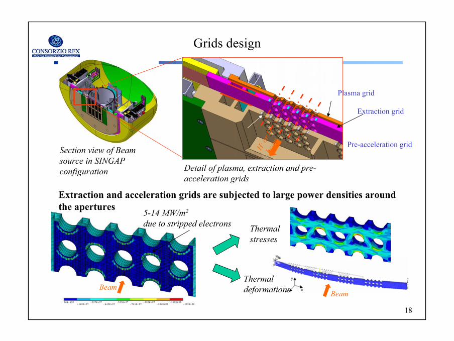
Section view of Beamsource in SINGAP configuration Detail of plasma, extraction and pre-
acceleration grids
Plasma grid
Extraction grid
Pre-acceleration gridH- or
D-
beam
Grids design
5-14 MW/m2
due to stripped electrons
Extraction and acceleration grids are subjected to large power densities aroundthe apertures
Thermalstresses
Thermaldeformations Beam
Beam
19
19
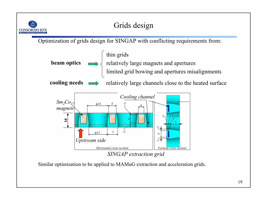
Optimization of grids design for SINGAP with conflicting requirements from:
thin gridsrelatively large magnets and apertureslimited grid bowing and apertures misalignments
beam optics
cooling needs relatively large channels close to the heated surface
Grids design
φ13 7
φ15 5 4
1 3
6
5
1 1
7
1 1
1
Horizontal cross section Vertical cross section
Sm2Co17magnets
Cooling channel
SINGAP extraction grid
Similar optimisation to be applied to MAMuG extraction and acceleration grids.
10
Upstream side
20
20
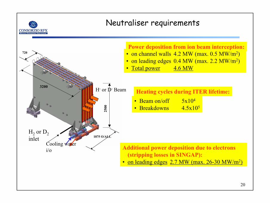
Neutraliser requirements
2500
3200
1875 O/ALL
720
H2 or D2inlet
Cooling water i/o
H- or D- Beam
• on channel walls 4.2 MW (max. 0.5 MW/m2)• on leading edges 0.4 MW (max. 2.2 MW/m2)• Total power 4.6 MW
Power deposition from ion beam interception:
• Beam on/off 5x10⁴
• Breakdowns 4.5x10⁵
Heating cycles during ITER lifetime:
Additional power deposition due to electrons(stripping losses in SINGAP):
• on leading edges 2.7 MW (max. 26-30 MW/m2)
21
21
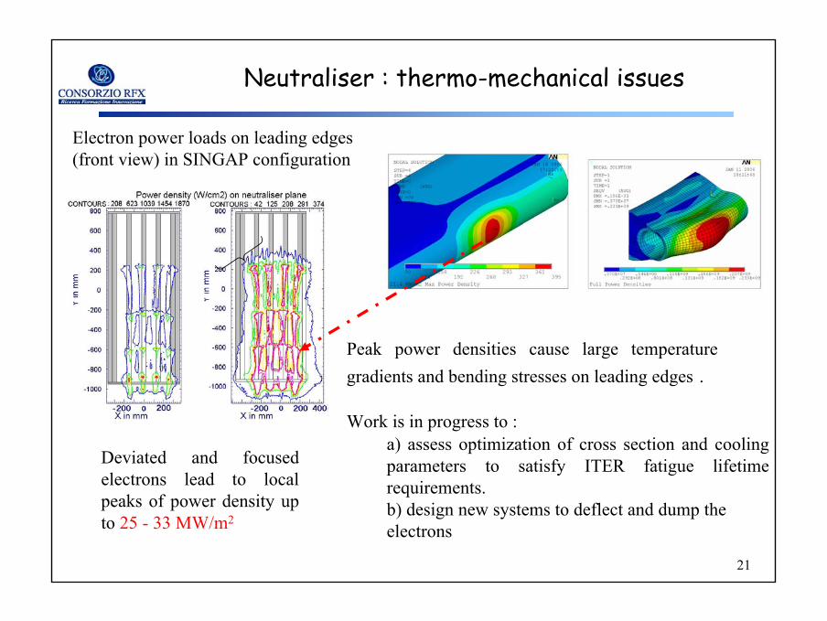
Electron power loads on leading edges(front view) in SINGAP configuration
Neutraliser : thermo-mechanical issues
Deviated and focusedelectrons lead to localpeaks of power density up to 25 - 33 MW/m2
Peak power densities cause large temperature gradients and bending stresses on leading edges .
Work is in progress to :a) assess optimization of cross section and cooling parameters to satisfy ITER fatigue lifetime requirements.b) design new systems to deflect and dump the electrons
22
22
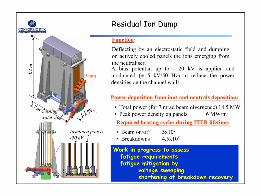
Residual Ion Dump
Function:
Deflecting by an electrostatic field and dumping on actively cooled panels the ions emerging fromthe neutraliser.
Coolingwater i/o
BeamA bias potential up to - 20 kV is applied and modulated (± 5 kV/50 Hz) to reduce the power densities on the channel walls.
Insulated panels-20 kV
2.7 m
3.2
m
1.3 m• Total power (for 7 mrad beam divergence) 18.5 MW• Peak power density on panels 6 MW/m2
• Beam on/off 5x10⁴
• Breakdowns 4.5x10⁵
Power deposition from ions and neutrals deposition:
Required heating cycles during ITER lifetime:
Work in progress to assessfatigue requirementsfatigue mitigation by
voltage sweeping shortening of breakdown recovery
23
23
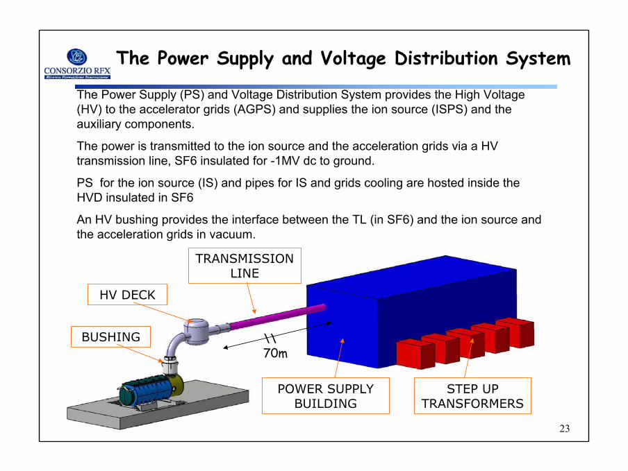
The Power Supply and Voltage Distribution System
The Power Supply (PS) and Voltage Distribution System provides the High Voltage (HV) to the accelerator grids (AGPS) and supplies the ion source (ISPS) and the auxiliary components.
The power is transmitted to the ion source and the acceleration grids via a HV transmission line, SF6 insulated for -1MV dc to ground.
PS for the ion source (IS) and pipes for IS and grids cooling are hosted inside the HVD insulated in SF6
An HV bushing provides the interface between the TL (in SF6) and the ion source and the acceleration grids in vacuum.
STEP UP TRANSFORMERS
POWER SUPPLY BUILDING
TRANSMISSION LINE
HV DECK
BUSHING \\70m
24
24
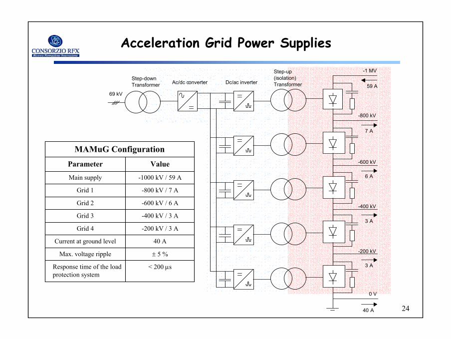
Acceleration Grid Power Supplies
0 V
-1 MV
Ac/dc converter Dc/ac inverter
Step-up (isolation)Transformer
-800 kV
-600 kV
-400 kV
-200 kV
69 kV59 A
7 A
6 A
3 A
3 A
40 A
Step-down Transformer
MAMuG Configuration
< 200 µsResponse time of the load protection system
± 5 %Max. voltage ripple
40 ACurrent at ground level
-200 kV / 3 AGrid 4
-400 kV / 3 AGrid 3
-600 kV / 6 AGrid 2
-800 kV / 7 AGrid 1
-1000 kV / 59 AMain supply
ValueParameter
25
25
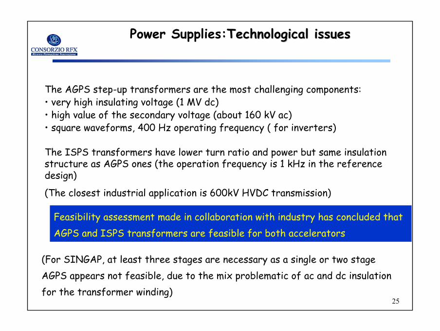
The AGPS step-up transformers are the most challenging components:• very high insulating voltage (1 MV dc)• high value of the secondary voltage (about 160 kV ac) • square waveforms, 400 Hz operating frequency ( for inverters)
The ISPS transformers have lower turn ratio and power but same insulation structure as AGPS ones (the operation frequency is 1 kHz in the reference design)
(The closest industrial application is 600kV HVDC transmission)
Power Supplies:TechnologicalTechnological issuesissues
(For SINGAP, at least three stages are necessary as a single or two stage AGPS appears not feasible, due to the mix problematic of ac and dc insulation for the transformer winding)
Feasibility assessment made in collaboration with industry has concluded that AGPS and ISPS transformers are feasible for both accelerators
26
26
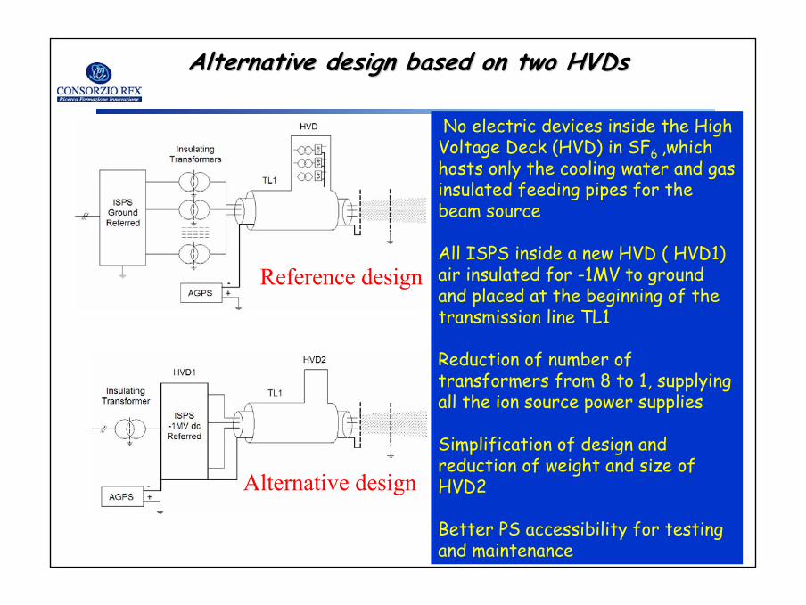
Alternative design based on two Alternative design based on two HVDsHVDs
Reference design
Alternative design
No electric devices inside the High Voltage Deck (HVD) in SF6 ,which hosts only the cooling water and gas insulated feeding pipes for the beam source
All ISPS inside a new HVD ( HVD1) air insulated for -1MV to ground and placed at the beginning of the transmission line TL1
Reduction of number of transformers from 8 to 1, supplying all the ion source power supplies
Simplification of design and reduction of weight and size of HVD2
Better PS accessibility for testing and maintenance
27
27
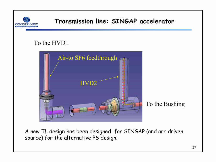
Transmission line: SINGAP accelerator
A new TL design has been designed for SINGAP (and arc drivensource) for the alternative PS design.
To the HVD1
HVD2
To the Bushing
Air-to SF6 feedthrough
28
28
Transmission line: Open issues
• Cooling water for beam services
•Current leakage depending on temperature.
•Metal corrosion due to electrolysis.
•SF6-epoxy insulation [1]
•Surface charge accumulation on spacers.
•Radiation Induced Conductivity effects on spacers electric fielddistribution.
•Metal particles
•Effectiveness increase of manufacturing-installation procedures for particle control.
•Design adaptation of the spacer and screens to cope with the unavoidable presence of particles inside the TLs and HVD
[1] A. De Lorenzi, et al (P3-B-382).
29
29
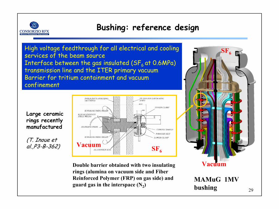
Bushing: reference design
High voltage feedthrough for all electrical and cooling services of the beam sourceInterface between the gas insulated (SF6 at 0.6MPa) transmission line and the ITER primary vacuum Barrier for tritium containment and vacuum confinement
SF6Vacuum
Double barrier obtained with two insulating rings (alumina on vacuum side and Fiber Reinforced Polymer (FRP) on gas side) and guard gas in the interspace (N2)
Large ceramic rings recently manufactured
(T. Inoue et al.,P3-B-362)
SF6
Vacuum
MAMuG 1MV bushing
30
30
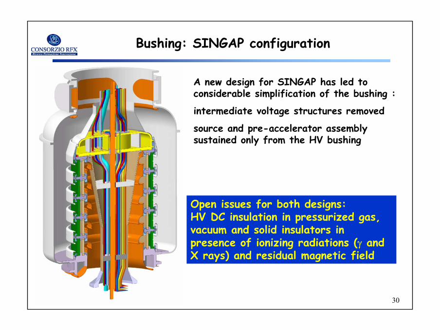
Bushing: SINGAP configuration
A new design for SINGAP has led to considerable simplification of the bushing :
intermediate voltage structures removed
source and pre-accelerator assembly sustained only from the HV bushing
Open issues for both designs:HV DC insulation in pressurized gas, vacuum and solid insulators in presence of ionizing radiations (γ and X rays) and residual magnetic field
31
31
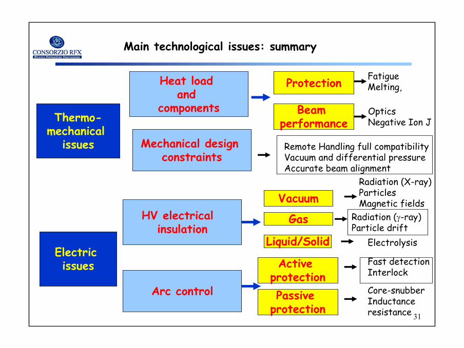
Main technological issues: summary
Thermo-mechanical
issues
Electric issues
Heat load and
components
Mechanical design constraints
Protection
Beamperformance
FatigueMelting,
OpticsNegative Ion J
Remote Handling full compatibility Vacuum and differential pressureAccurate beam alignment
HV electrical insulation
Arc control
Vacuum
Gas
Radiation (X-ray)ParticlesMagnetic fields
ElectrolysisLiquid/Solid
Radiation (γ-ray)Particle drift
ActiveprotectionPassive
protection
Fast detectionInterlock
Core-snubberInductanceresistance
32
32
Test Facility
• As most of the issues are strongly coupled, those of them still open can be tackled and solved only by testing a full scale NBI at full performance in D and H.
• A Test Facility where to install and operate a NBI before operation in ITER is therefore mandatory in order to provide a reliable system.
• Such a Test Facility should also allow all the needed adjustments and modifications to be performed in order to optimise the system.
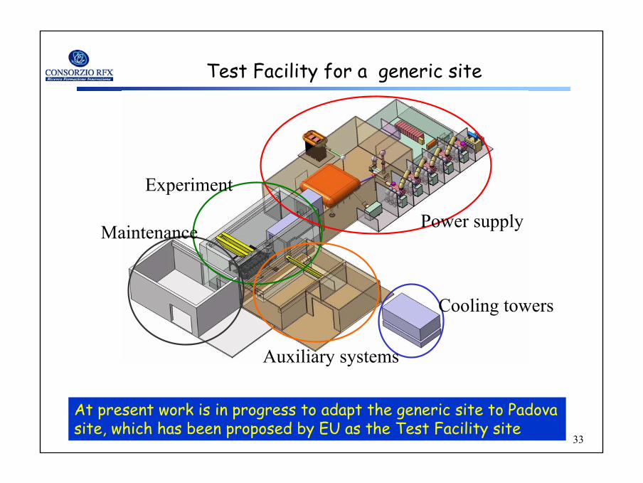
• In the framework of the EU activities a schematic design for a generic site has been prepared
33
33
Power supplyMaintenance
Experiment
Auxiliary systems
Cooling towers
At present work is in progress to adapt the generic site to Padovasite, which has been proposed by EU as the Test Facility site
Test Facility for a generic site
34
34
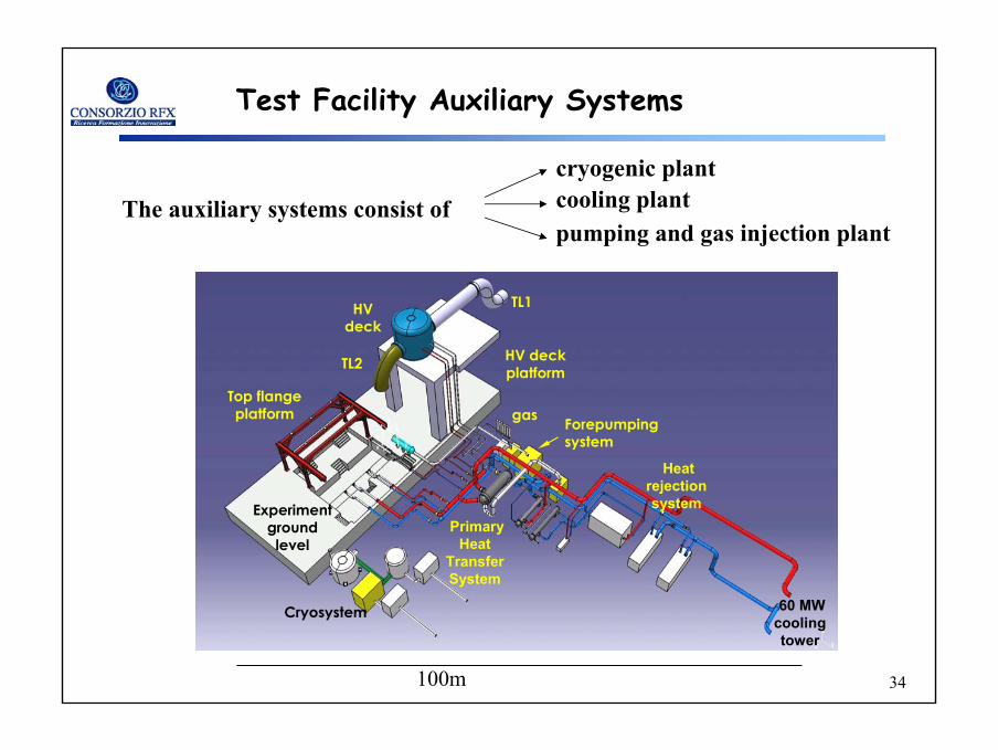
Test Facility Auxiliary Systems
Cryosystem
Forepumpingsystem
Top flange platform
60 MW cooling tower
Heat rejection system
Primary Heat
Transfer System
HV deck
TL2
TL1
HV deckplatform
Experiment ground
level
gas
100m
The auxiliary systems consist of
cryogenic plantcooling plantpumping and gas injection plant
35
35
Conclusions
A thorough revision activity of the ITER NBI design promoted by EU has led to the identification of several technological issues.
Some of the issues have been solved, others are in the process of being solved, others remains open.
The complexity of the design suggests the construction of a Test Facilty to test the NBI before operation in ITER.
Several posters give more details
36
36
Today POSTERS
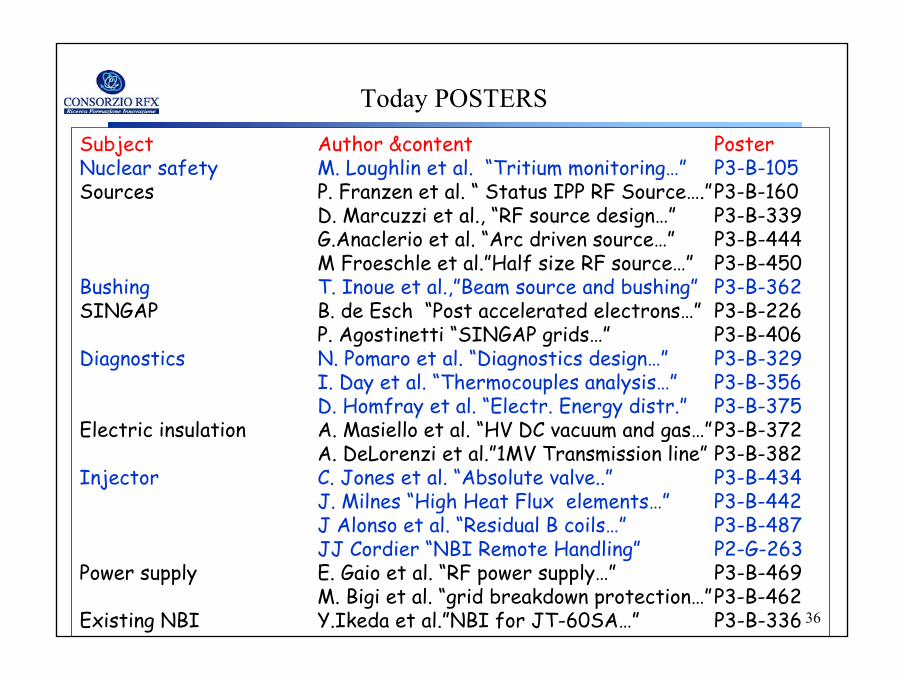
Subject Author &content PosterNuclear safety M. Loughlin et al. “Tritium monitoring…” P3-B-105Sources P. Franzen et al. “ Status IPP RF Source….”P3-B-160
D. Marcuzzi et al., “RF source design…” P3-B-339G.Anaclerio et al. “Arc driven source…” P3-B-444M Froeschle et al.”Half size RF source…” P3-B-450
Bushing T. Inoue et al.,”Beam source and bushing” P3-B-362SINGAP B. de Esch “Post accelerated electrons…” P3-B-226
P. Agostinetti “SINGAP grids…” P3-B-406Diagnostics N. Pomaro et al. “Diagnostics design…” P3-B-329
I. Day et al. “Thermocouples analysis…” P3-B-356D. Homfray et al. “Electr. Energy distr.” P3-B-375
Electric insulation A. Masiello et al. “HV DC vacuum and gas…”P3-B-372A. DeLorenzi et al.”1MV Transmission line” P3-B-382
Injector C. Jones et al. “Absolute valve..” P3-B-434J. Milnes “High Heat Flux elements…” P3-B-442J Alonso et al. “Residual B coils…” P3-B-487JJ Cordier “NBI Remote Handling” P2-G-263
Power supply E. Gaio et al. “RF power supply…” P3-B-469M. Bigi et al. “grid breakdown protection…”P3-B-462
Existing NBI Y.Ikeda et al.”NBI for JT-60SA…” P3-B-336
37
37
38
38
Spare slides

39
39
• simplification of the high voltage transmission line and bushing
• less critical and smaller postinsulators forgrids support
• plane grids (plasma, extraction and pre-acceleration)
• easier horizontal and vertical beam steering by means of translations of the grounded grid
SINGAP accelerator
The SINGAP accelerator has been designed

40
40
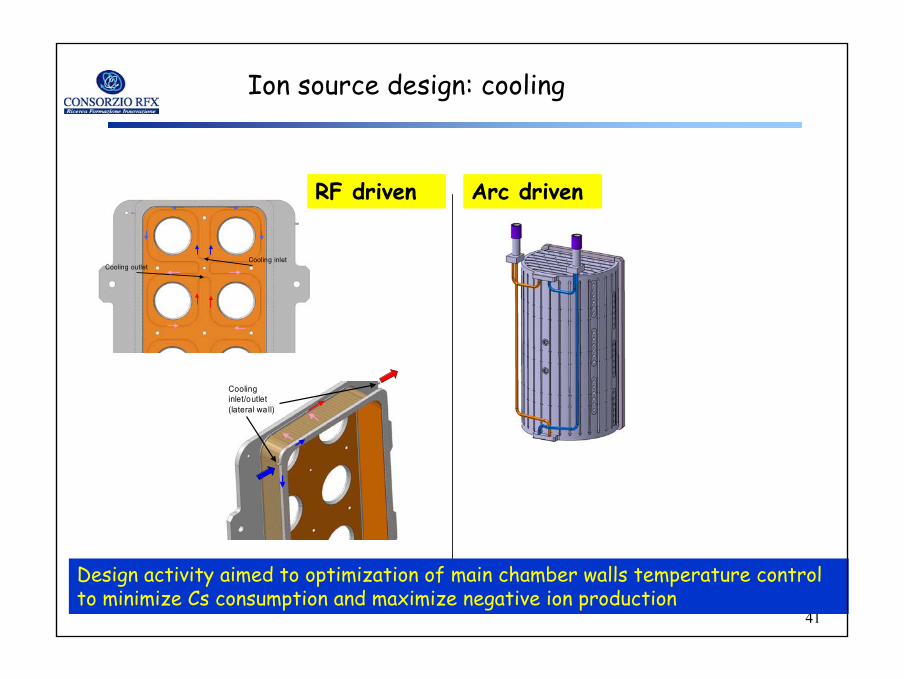
Cooling inletCooling outlet
Cooling inlet/outlet (lateral wall)
Design activity aimed to optimization of main chamber walls temperature control to minimize Cs consumption and maximize negative ion production
Ion source design: cooling
RF driven Arc driven
41
41
Cooling inletCooling outlet
Cooling inlet/outlet (lateral wall)
Design activity aimed to optimization of main chamber walls temperature control to minimize Cs consumption and maximize negative ion production
Ion source design: cooling
RF driven Arc driven
42
42
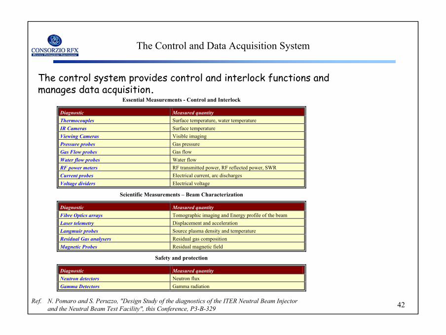
Essential Measurements - Control and Interlock
Diagnostic Measured quantity Thermocouples Surface temperature, water temperature IR Cameras Surface temperature Viewing Cameras Visible imaging Pressure probes Gas pressure Gas Flow probes Gas flow Water flow probes Water flow RF power meters RF transmitted power, RF reflected power, SWR Current probes Electrical current, arc discharges Voltage dividers Electrical voltage
Scientific Measurements – Beam Characterization
Diagnostic Measured quantity Fibre Optics arrays Tomographic imaging and Energy profile of the beam Laser telemetry Displacement and acceleration Langmuir probes Source plasma density and temperature Residual Gas analysers Residual gas composition Magnetic Probes Residual magnetic field
Safety and protection
Diagnostic Measured quantity Neutron detectors Neutron flux Gamma Detectors Gamma radiation
The control system provides control and interlock functions and manages data acquisition.
The Control and Data Acquisition System
Ref. N. Pomaro and S. Peruzzo, "Design Study of the diagnostics of the ITER Neutral Beam Injector and the Neutral Beam Test Facility", this Conference, P3-B-329
43
43
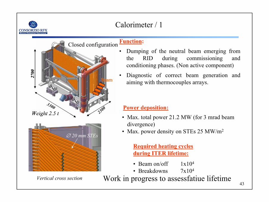
Calorimeter / 1
Function:
• Dumping of the neutral beam emerging fromthe RID during commissioning and conditioning phases. (Non active component)
• Diagnostic of correct beam generation and aiming with thermocouples arrays.
Vertical cross section
∅ 20 mm STEs
• Max. total power 21.2 MW (for 3 mrad beamdivergence)
• Max. power density on STEs 25 MW/m2
Power deposition:
• Beam on/off 1x10⁴
• Breakdowns 7x10⁴
Required heating cyclesduring ITER lifetime:
Weight 2.5 t
Beam
2700
3300230
0Weight 2.5 t
BeamBeam
2700
3300230
0
Closed configuration
Work in progress to assessfatiue lifetime
44
44
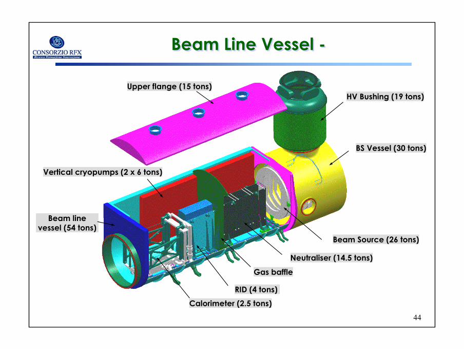
Upper flange (15 tons)
Vertical cryopumps (2 x 6 tons)
Calorimeter (2.5 tons)
HV Bushing (19 tons)
Gas baffle
RID (4 tons)
Neutraliser (14.5 tons)
Beam Source (26 tons)
BS Vessel (30 tons)
Beam Line Vessel -Beam Line Vessel -
Beam line vessel (54 tons)
45
45
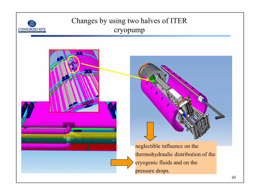
Changes by using two halves of ITER cryopump
neglectible influence on thethermohydraulic distribution of thecryogenic fluids and on thepressure drops.
46
46
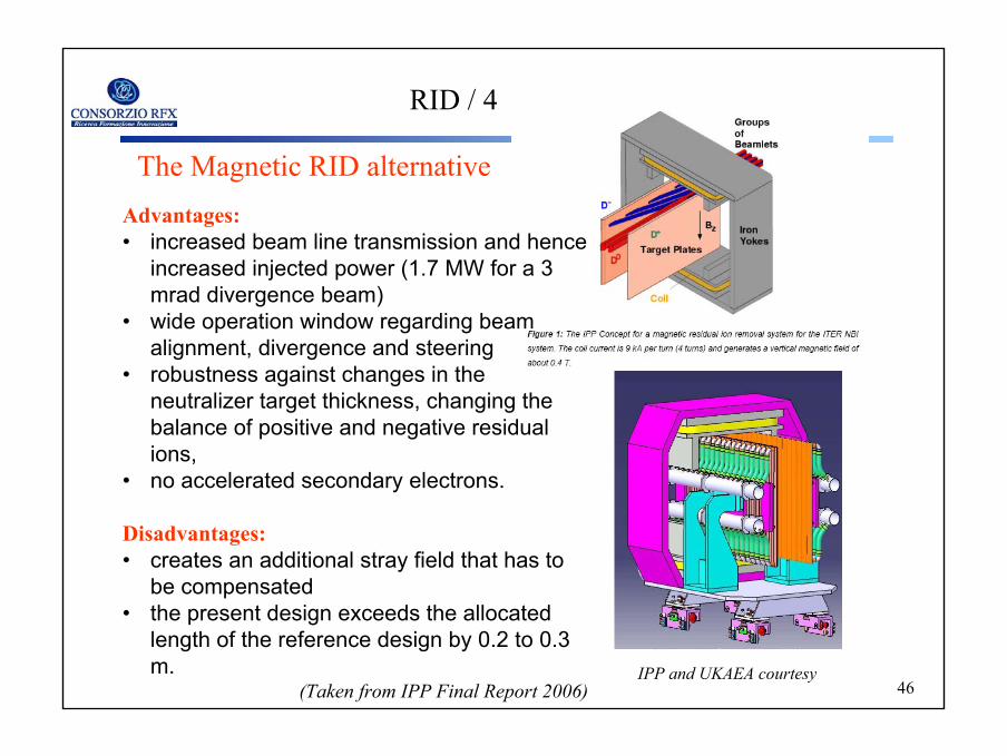
RID / 4
The Magnetic RID alternative
IPP and UKAEA courtesy
Advantages:• increased beam line transmission and hence
increased injected power (1.7 MW for a 3 mrad divergence beam)
• wide operation window regarding beamalignment, divergence and steering
• robustness against changes in the neutralizer target thickness, changing the balance of positive and negative residualions,
• no accelerated secondary electrons.
Disadvantages:• creates an additional stray field that has to
be compensated• the present design exceeds the allocated
length of the reference design by 0.2 to 0.3 m.
(Taken from IPP Final Report 2006)
47
47
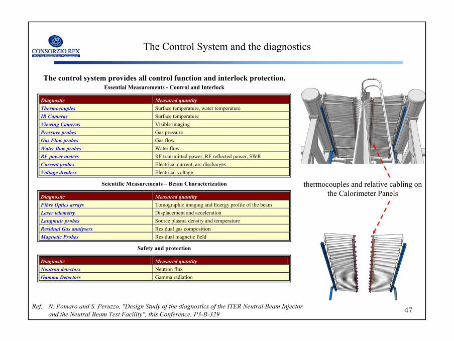
Essential Measurements - Control and Interlock
Diagnostic Measured quantity Thermocouples Surface temperature, water temperature IR Cameras Surface temperature Viewing Cameras Visible imaging Pressure probes Gas pressure Gas Flow probes Gas flow Water flow probes Water flow RF power meters RF transmitted power, RF reflected power, SWR Current probes Electrical current, arc discharges Voltage dividers Electrical voltage
Scientific Measurements – Beam Characterization
Diagnostic Measured quantity Fibre Optics arrays Tomographic imaging and Energy profile of the beam Laser telemetry Displacement and acceleration Langmuir probes Source plasma density and temperature Residual Gas analysers Residual gas composition Magnetic Probes Residual magnetic field
Safety and protection
Diagnostic Measured quantity Neutron detectors Neutron flux Gamma Detectors Gamma radiation
The control system provides all control function and interlock protection.
thermocouples and relative cabling on the Calorimeter Panels
The Control System and the diagnostics
Ref. N. Pomaro and S. Peruzzo, "Design Study of the diagnostics of the ITER Neutral Beam Injector and the Neutral Beam Test Facility", this Conference, P3-B-329
48
48
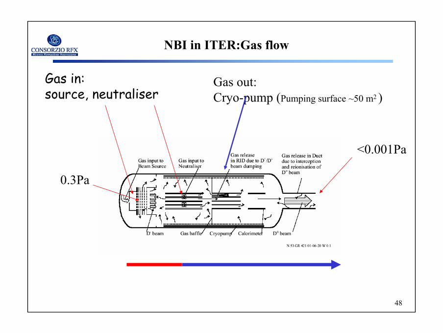
NBI in ITER:Gas flow
Gas in: source, neutraliser
0.3Pa
<0.001Pa
Gas out: Cryo-pump (Pumping surface ~50 m2 )
49
49
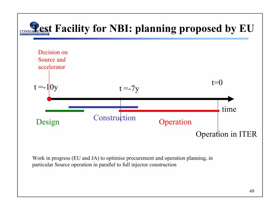
Test Facility for NBI: planning proposed by EU
time
Operation in ITER
t=0t =-7yt =-10y
OperationConstructionDesign
Decision on Source and accelerator
Work in progress (EU and JA) to optimise procurement and operation planning, in particular Source operation in parallel to full injector construction
50
50
The Power Supply System of the ITER NB InjectorLoad protection in case of grid breakdownLoad protection in case of grid breakdown
In case of grid breakdown (a routine events) the energy stored in the filter and stray capacitance is discharged and can damage the grids.
Protection by DC breakers is not feasible due to the high voltagePassive protections (core snubbers) plus fast switch-off of the inverters is foreseen
Status of the workStatus of the workRevision of the analyses of the reference designImprovement of the model simulated (unprotected stray capacitances, rectifier diodes)Analysis of the core snubber modeling and design (concentrated or distributed )Assessment of the passive and active protections for the SINGAP case [3]
[3 M. Bigi, V. Toigo, L. Zanotto, “Protections Against Grid Breakdowns in the ITER Neutral Beam Injector Power Supplies”, ID469 this conference

51
51
Thermomechanical issues
1)Heat load and effect on componentscomponents protection ( localised enhanced heat load and surface
damages , coolant leakage, outgassing, sputtering) fatigue and thermal cycles and sweeping
beam performance ( source wall temperature and current density (negative ion production), optics and deformation of the grids
2) Mechanical design and constraintsRemote Handling full compatibility vacuum and differential pressure requirementsaccurate beam alignment
52
52
Electric issues
1) HV electrical insulation in different mediavacuum ( radiation: X rays, particles emitted by thermal emission, sputtering, arcs , effect of magnetic fields both residual and applied)gas (radiation: gamma rays, drift of chargesliquid or solid vacuum. (electrolysis)
2) Arc controlmaximum energy tolerable to avoid de-conditioning
passive (core snubber , resistance, inductance)Protection
active (fast detection and intervention system)
53
53
5 accelerationgrids
Plasma and extraction grids
-200
-400
-600
-800
-1 M
V
0 kV
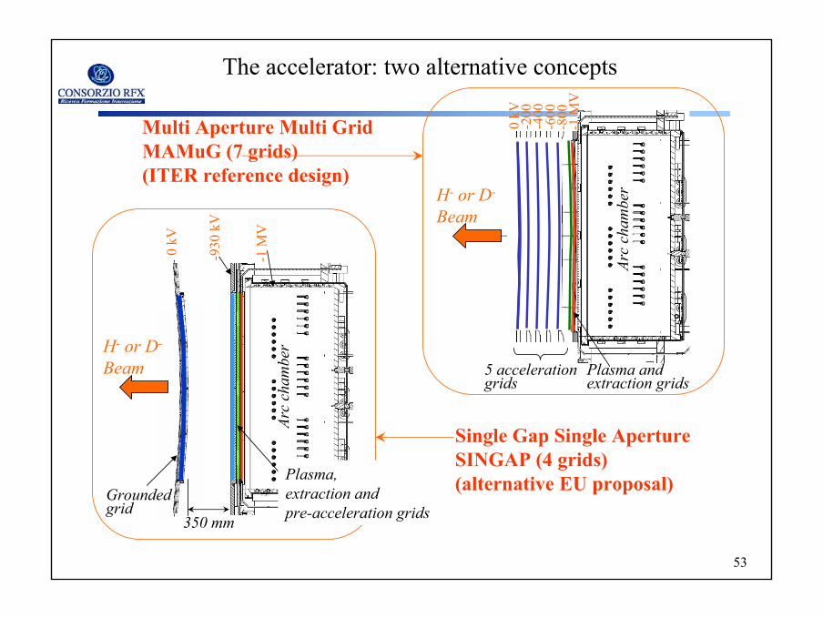
Multi Aperture Multi GridMAMuG (7 grids)(ITER reference design)
H- or D-
Beam
Single Gap Single ApertureSINGAP (4 grids)(alternative EU proposal)
350 mm
H- or D-
Beam
The accelerator: two alternative concepts
Plasma,extraction andpre-acceleration grids
Groundedgrid
0 kV
-930
kV
-1 M
VAr
cch
ambe
r
Arc
cham
ber
54
54
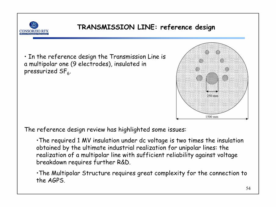
TRANSMISSION LINE: reference design
• In the reference design the Transmission Line is a multipolar one (9 electrodes), insulated in pressurized SF6.
1500 mm
250 mm
The reference design review has highlighted some issues:
•The required 1 MV insulation under dc voltage is two times the insulation obtained by the ultimate industrial realization for unipolar lines: the realization of a multipolar line with sufficient reliability against voltage breakdown requires further R&D.
•The Multipolar Structure requires great complexity for the connection to the AGPS.