Embed Size (px)
Citation preview
Lehrstuhl fur Elektrische Antriebssysteme und Leistungselektronikder Technischen Universitat Munchen
The Performance Improvementsof Self-sensing Control
for Permanent Magnet Synchronous MachinesXiaocan Wang
Vollstaendiger Abdruck der von der Fakultat fur Elektrotechnik und Informations-technik der Technischen Universitat Munchen zur Erlangung des akademischenGrades eines
Doktor-Ingenieurs
genehmigten Dissertation.
Vorsitzender: Univ.-Prof. Dr.-Ing. Hans-Georg HerzogPrufer der Dissertation:
1. Univ.-Prof. Dr.-Ing. Ralph M. Kennel2. Univ.-Prof. Dr.-Ing. Dieter GerlingUniversitat der Bundeswehr Munchen
Die Dissertation wurde am 30.09.2014bei der Technischen Universitat Muncheneingereicht und durch die Fakultat fur Elektrotechnik und Informationstechnik am03.02.2015angenommen.


I
Acknowledgments
This dissertation is a cumulative work involving the contributions of many peo-ple. Without their support, this dissertation would not have come to completion.This research work has been carried out during the years 2010-2014 in the Insti-tute for Electrical Drive Systems and Power Electronics, Technical University ofMunich. First, I would like to express my sincere thanks to mysupervisor, Prof.Dr.-Ing. Ralph M. Kennel, for his valuable comments and guidance throughout thework as well as for allowing me a high degree of freedom in my research activities.His inspiring guidance and encouragement have been of enormous significance tome.
I am indebted to my another advisor, Prof. Robert D. Lorenz, for the opportuni-ties and guidance that he has given. His unselfish support andtraining have greatlyenhanced my skills in almost every aspect of my professionallife. I have truly en-joyed my time at WEMPEC, University of Wisconsin-Madison inNovember 2013.Many brilliant people including, Wei, Chen-Yun, Larry and Kang as well as theother students have made it a pleasure to learn and work there.
I am appreciate the help of Prof. Dr.-Ing. Dieter Gerling in University of FederalDefense Munich, that he is very kind to provide the lab equipments of the Depart-ment of Electrical Drives and Actuators free to me. He gives us the permission toenable the collaboration and also pays much attention aboutmy doctoral thesis.
In addition, I wish to send my warmest thanks to Peter, Fengxiang, Zhixun, Dr.Gao, Dr. Dajaku and all our EAL and EAA team members during these years, fortheir close co-operation, for making the time spent in Munich worthwhile and helpin every day life.
The financial support of the Chinese Council Scholarship is gratefully acknowl-edged.
I am deeply indebted to my big family for giving me all best fora good life basisand encouraged me during my work. The help of my mother takingcare of my sonmake my Ph.D research work to be continued on. Finally, I would like to thank myhusband Wei for his love, understanding and support, and ourlovely son Leon forhis big smiles.

III
Abstract
This thesis presents a general solution for the problem of position self-sensingwith surface-mounted permanent magnet synchronous machines at zero and lowspeeds using high frequency signal injection, and introduces two different novel de-signs of interior permanent magnet synchronous machines with concentrated wind-ings which are attractive to the self-sensing control system and have been verified byrespective experimental results. Furthermore, considering the efficiency optimiza-tion, the extra losses in a permanent magnet synchronous machine resulting fromthe high frequency injection are analyzed. By using the proposed observer-basedmodel predictive torque control scheme, the closed-loop self-sensing technology ofa permanent magnet synchronous machine can be achieved.
Kurzzusammenfassung
Diese Arbeit zeigt eine funktionsfahige Losung fur die Geberlose Positionserfas-sung bei niedrigen Drehzahlen und im Stillstand fur permanenterregte Synchron-maschinen mit Oberflachenmagneten mit Hilfe der Einspeisung hochfrequenter Sig-nale. Zwei unterschiedliche neuartige Maschinendesigns von Synchronmaschinenmit vergrabenen Magneten und konzentrierten Wicklungen die fur die GeberloseRegelung geeignet sind wurden vermessen. Weiterhin wurdendie zusatzlichen Ver-luste, die in der permanenterregten Synchronmaschine aufgrund der hochfrequentenSignale entstehen analysiert mit dem Ziel der Wirkungsgradoptimierung. Durch dievorgestellte Methode der modellpradiktiven Drehmomentregelung wird ein Geber-lose Regelung fur die permanenterregte Synchronmaschinerealisiert, die auf einemBeobachter basierend.

CONTENTS V
Contents
Acknowledgments I
Abstract III
1 Introduction 11.1 Background . . . . . . . . . . . . . . . . . . . . . . . . . . . . . . 11.2 Contributions . . . . . . . . . . . . . . . . . . . . . . . . . . . . . 3
2 The State-of-the-Art Review 52.1 Overview of Permanent Magnet Synchronous Machines . . . .. . . 5
2.1.1 Surface-mounted PMSMs . . . . . . . . . . . . . . . . . . 52.1.2 Interior PMSMs . . . . . . . . . . . . . . . . . . . . . . . 72.1.3 Stator Winding Types . . . . . . . . . . . . . . . . . . . . . 8
2.2 Traditional Control Strategies . . . . . . . . . . . . . . . . . . . .. 102.2.1 Field-Oriented Control . . . . . . . . . . . . . . . . . . . . 102.2.2 Direct Torque Control . . . . . . . . . . . . . . . . . . . . 11
2.3 Self-sensing Control . . . . . . . . . . . . . . . . . . . . . . . . . 142.3.1 Back-Electromotive Force and State Observers . . . . . .. 142.3.2 High-Frequency Injection Control . . . . . . . . . . . . . . 16
2.4 Model Predictive Control . . . . . . . . . . . . . . . . . . . . . . . 192.5 Loss Minimization Control . . . . . . . . . . . . . . . . . . . . . . 21
3 Self-sensing Control of SPMSMs Based on Different High-FrequencyInjection Methods 253.1 Mathematical Model of PMSMs . . . . . . . . . . . . . . . . . . . 253.2 High-Frequency Model of SPMSMs . . . . . . . . . . . . . . . . . 273.3 Rotating Vector Injection Method for SPMSMs . . . . . . . . . .. 293.4 Pulsating Vector Injection Method For SPMSMs . . . . . . . . .. 32

VI CONTENTS
3.5 Implementation and Experimental Results . . . . . . . . . . . .. . 343.5.1 Hardware Description . . . . . . . . . . . . . . . . . . . . 343.5.2 Experimental Results . . . . . . . . . . . . . . . . . . . . . 35
3.6 Summary . . . . . . . . . . . . . . . . . . . . . . . . . . . . . . . 38
4 Estimation Accuracy Analysis for Injection-based Self-sensing Controlof IPMSMs 394.1 Novel CW-IPMSMs Design . . . . . . . . . . . . . . . . . . . . . 404.2 Machine Modeling and HF Injection Method . . . . . . . . . . . . 434.3 Analysis of Estimation Accuracy . . . . . . . . . . . . . . . . . . . 44
4.3.1 Saliency Analysis . . . . . . . . . . . . . . . . . . . . . . . 454.3.2 Cross Saturation Effect . . . . . . . . . . . . . . . . . . . . 474.3.3 High Frequency Inductance Effect . . . . . . . . . . . . . . 494.3.4 High Frequency Resistance Effect . . . . . . . . . . . . . . 504.3.5 FEM Results of Harmonic Distortion . . . . . . . . . . . . 51
4.4 Implementation and Experimental Results . . . . . . . . . . . .. . 554.4.1 Hardware Description . . . . . . . . . . . . . . . . . . . . 554.4.2 Experimental Results of Harmonic Distortion . . . . . . .. 554.4.3 Experimental Results of Estimation Accuracy . . . . . . .57
4.5 Summary . . . . . . . . . . . . . . . . . . . . . . . . . . . . . . . 60
5 Losses Analysis in IPMSMs Resulting from HF Injection for Self-sensingControl 635.1 New Stator Topology of IPMSM-2 . . . . . . . . . . . . . . . . . . 635.2 Analysis of MMF with HF Injection . . . . . . . . . . . . . . . . . 645.3 Analysis of Losses by HF Currents Harmonics . . . . . . . . . . .. 675.4 Proposed Analytical Solution of Eddy Current Loss with HF Injection 69
5.4.1 Specified Boundary of IPMSM-2 . . . . . . . . . . . . . . 705.4.2 Loss calculation of IPMSM-2 . . . . . . . . . . . . . . . . 70
5.5 Summary . . . . . . . . . . . . . . . . . . . . . . . . . . . . . . . 76
6 Observer-based Self-sensing Model Predictive Control ofIPMSMs 776.1 Model Predictive Torque Control with Finite Control Setof IPMSMs 786.2 Gopinath-Style Stator Flux Linkage Observer . . . . . . . . .. . . 796.3 Full-order Luenberger Rotor Position Observer . . . . . . .. . . . 816.4 Enhanced Luenberger-style Saliency Tracking Rotor Position Ob-
server . . . . . . . . . . . . . . . . . . . . . . . . . . . . . . . . . 836.5 Simulation Results . . . . . . . . . . . . . . . . . . . . . . . . . . 856.6 Implementation and Experimental Results . . . . . . . . . . . .. . 87

CONTENTS VII
6.7 Summary . . . . . . . . . . . . . . . . . . . . . . . . . . . . . . . 89
7 Conclusions and Future Work 917.1 Conclusions . . . . . . . . . . . . . . . . . . . . . . . . . . . . . . 917.2 Recommended Future Work . . . . . . . . . . . . . . . . . . . . . 92
A List of Nomenclature and Abbreviations 95A.1 Nomenclature . . . . . . . . . . . . . . . . . . . . . . . . . . . . . 95A.2 Abbreviations . . . . . . . . . . . . . . . . . . . . . . . . . . . . . 97
Appendix 94
B List of Publications 99B.1 Published Conference Papers . . . . . . . . . . . . . . . . . . . . . 99B.2 Published Journal Papers . . . . . . . . . . . . . . . . . . . . . . . 100B.3 Submitted Journal Papers . . . . . . . . . . . . . . . . . . . . . . . 100
Bibliography 101

VIII CONTENTS
1
CHAPTER 1
Introduction
1.1 Background
Permanent magnet synchronous machines (PMSMs) are widely used in low andmedium power applications such as computer peripheral equipments, robotics, ad-justable speed drives and electric vehicles. PMSMs have numerous advantages incomparison to other machines that are conventionally used for AC motor drives.The stator current of the induction machines contains magnetizing as well as torque-producing components. The use of permanent magnets in the rotor of PMSMsmakes it unnecessary to supply magnetizing current throughthe stator for constantair-gap flux, and the stator current is only needed to producethe torque. Hence forthe same torque output, PMSMs will operate at a higher power factor (because ofthe absence of magnetizing current), and will be more efficient than induction ma-chines. The development of PMSMs aims to remove the foregoing disadvantagesof the excited synchronous machines by replacing the field coils, DC power supplyand slip rings with the permanent magnet [1] [2].
Control strategies of electrical machines are the key points of high-performanceservo-drive systems. Since PMSMs are widely used in industrial applications, thecontrol system of PMSMs has become a focus research topic forthe last decades [3].
Nowadays the control performance of the electric drives still has space of im-provements [4]. The traditional control methods field-oriented control (FOC) anddirect torque control (DTC) are the most popular high-performance control strate-gies, and position sensors such as the resolver or the absolute encoder are requiredin the high-performance electric drive system in order to determine the rotor posi-tion. However, in industrial applications, the presence ofsuch a position encoder
2 CHAPTER 1. INTRODUCTION
reveals several disadvantages in the areas of cost, reliability, machine size, and noiseinterference. Therefore, there has been much research on eliminating the positionencoder mounted to the rotor of the electric machines by obtaining the rotor posi-tion information indirectly. This control method without aposition sensor in theelectric drives is called sensorless control, and is named as self-sensing control inthis thesis, i.e. using the motor itself as the sensor [5].
Self-sensing control methods can be divided into three categories:
• Based on the back electromotive force (back-EMF) or extended EMF meth-ods;
• Based on the mathematical models of electrical machines using state ob-servers;
• Based on the high-frequency (HF) injection.
The self-sensing control with HF injection method shows good rotor position/speedestimation results at zero & low speed [6] [7]. The HF injection signal (current orvoltage) is superimposed to the fundamental excitation. The applied signals inter-act with the rotor saliency or magnetic anisotropy of the motor, and the resultingresponse (voltage or current) is tracked to extract rotor position information.
Self-sensing control methods are applied in only a small fraction of all motordrive and actuator applications. A lot of schemes and concepts for self-sensingAC drive control providing good operation during standstill are already publishedin [8] [9] [10] [11] [12]. Acceptance by industry, however, is not very extended.The main reasons for hesitations in industry are enhanced processing performancebeing necessary for the controller or signal processor additional sensors or hardwareparameters to be adjusted with respect to self-sensing control.
Self-sensing control of different kinds of PMSMs in the whole speed range is stilla challenge [13]. The industry is concerned regarding aboutthe excellent perfor-mance of the self-sensing control at each operation point [14] [15] [16] [17]. Theestimated position and speed need to be very accurate in someareas, such as theaircraft industry, textile industry and so on.
Self-sensing control of PMSMs is attractive for the industry communities sincethe additional encoder can be relieved from the rotor, whichis a kind of modernelectrical drive systems. More than half of the electrical energy provided is used toproduce mechanical motion by electric drives. Unfortunately, most of these drivesare based on old technology and dissipate 25% to 40% of the supplied energy whichcould be saved by modern electrical drive systems and power electronics. Thisshows the importance and significance of the efficiency optimization of the elec-tric drives using modern control methods. However, for the self-sensing control of
1.2. CONTRIBUTIONS 3
PMSMs based on the HF injection method, there are some extra losses due to theinjection signals. How to make a balance between the cost of the position encoderand the extra losses consumption is a new topic for the modernindustry. The lossesin PMSMs resulting from the HF injection are need to be researched.
1.2 Contributions
In this thesis, the mainly two types of PMSMs: surface-mounted permanent magnetsynchronous machines (SPMSMs) and interior permanent magnet synchronous ma-chines (IPMSMs) are investigated and analyzed. In order to realize the self-sensingcontrol of PMSMs in the whole speed range, HF injection method is used at zero &very low speed, and the observer-based self-sensing model predictive torque controlmethod is implemented at medium and high speed.
The SPMSMs do not have the saliency phenomena in their geometry resulting indifficulties to implement the sailency-tracking self-sensing control strategies. Com-mercial SPMSM has been adapted for self-sensing applications by using the rotatingand pulsating HF voltage vector injection methods. The experimental results verifythat the SPMSM can reach very high performance with good self-sensing propertiesregarding the accuracy of the estimated position/speed of electric drives.
The IPMSMs have highlights due to the geometric saliency especially for theself-sensing control based on HF injection method. Two different novel designs ofIPMSMs with concentrated windings (CW-IPMSMs) having lower space harmoniccontents are tested and analyzed. Based on the machine design and HF injectionself-sensing control method, the investigation insight the advantages and future ap-plication of the new designed CW-IPMSMs, which are essential and have not beendone before. On the machine design side, these two novel designed machines havebeen proven to have lower losses even when including the eddycurrent losses. Onthe control performance side, it has been analyzed that HF current responses ofPMSMs, with and without considering eddy current effects, are significantly differ-ent. Thus, due to the significant eddy current loss reduction, it is a promising topicto apply the self-sensing method for the new machines in order to get the optimalefficiency and control performance of the electric drives.
Considering the efficiency optimization, the losses in IPMSMs resulting from theHF injection for the self-sensing control are analyzed. Theconventional losses cal-culation is mainly based on the finite element method (FEM), which are exhaustedtime consuming. A analytical solution is proposed to designthe eddy current lossmodel. This technology can be used both with and without the HF injection in themachine, and also is meaningful when the machine is operatedunder extra high

4 CHAPTER 1. INTRODUCTION
speed.When the machines are operated under medium and high speed, the back-EMF
which is proportional to the speed can be utilized to do the position & speed estima-tion. The self-sensing control method of IPMSMs is implemented by the enhancedLuenberger-style back-EMF tracking observer. Furthermore, the self-sensing con-trol strategy is based on the model predictive control with finite control set (FCS-MPC), and the Gopinath-style stator flux linkage observer isused to do the fluxestimation which has not been done before.
5
CHAPTER 2
The State-of-the-Art Review
2.1 Overview of Permanent Magnet Synchronous Ma-chines
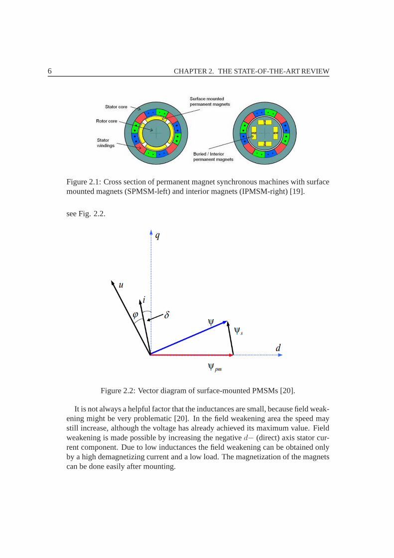
Permanent magnet synchronous machines (PMSMs) have been widely used in var-ious motion control applications. To maximize the power conversion performance,PMSMs need a systematic design. The objective of this section is to initiate a gen-eral review of PMSMs. PMSMs mainly can be classified into two types: surface-mounted permanent magnet synchronous machines (SPMSMs) and interior perma-nent magnet synchronous machines (IPMSMs). The general topologies of SPMSMsand IPMSMs are shown in Fig. 2.1. Usually, IPMSMs are used forhigh speed ap-plication because of the reluctance torque, and also for bigtorque response applica-tion because the high permanent-magnets mechanical strength; SPMSMs are usedfor constant speed application because of the smooth air-gap flux density [18].
2.1.1 Surface-mounted PMSMs
The simplest and probably the cheapest rotor construction of PMSMs can be ob-tained by using surface-mounted permanent magnets [20]. The SPMSM is also themost commonly used model nowadays. Most motors for servo drives are SPMSMs.The armature reaction of this machine type is remarkably small, and the magnetshave a relative permeability similar to that of air, thus theeffective air-gap lengthis large and the magnetizing inductances are very low. This means that the statorflux-linkage is almost equal to the flux linkage created by thepermanent magnets,
6 CHAPTER 2. THE STATE-OF-THE-ART REVIEW
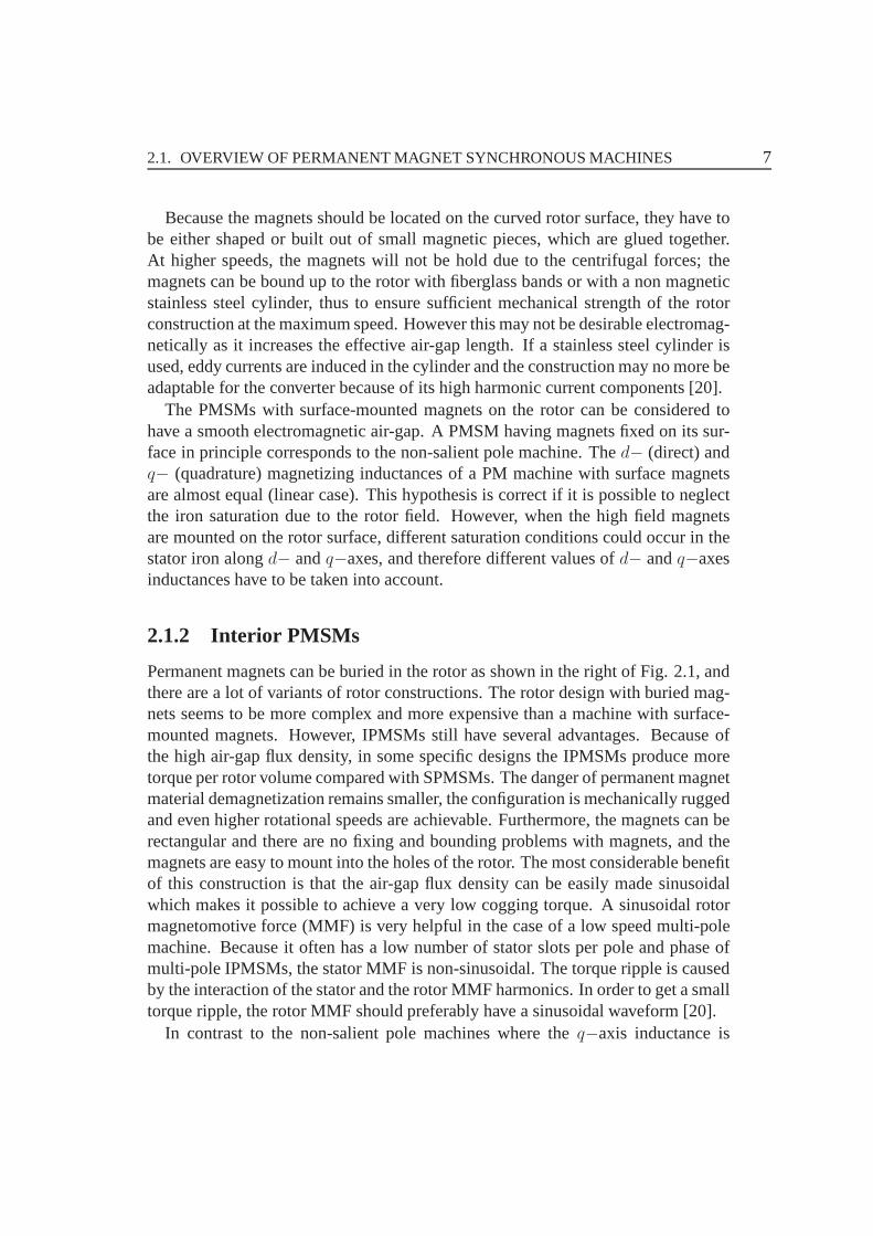
Figure 2.1: Cross section of permanent magnet synchronous machines with surfacemounted magnets (SPMSM-left) and interior magnets (IPMSM-right) [19].
see Fig. 2.2.
Figure 2.2: Vector diagram of surface-mounted PMSMs [20].
It is not always a helpful factor that the inductances are small, because field weak-ening might be very problematic [20]. In the field weakening area the speed maystill increase, although the voltage has already achieved its maximum value. Fieldweakening is made possible by increasing the negatived− (direct) axis stator cur-rent component. Due to low inductances the field weakening can be obtained onlyby a high demagnetizing current and a low load. The magnetization of the magnetscan be done easily after mounting.
2.1. OVERVIEW OF PERMANENT MAGNET SYNCHRONOUS MACHINES 7
Because the magnets should be located on the curved rotor surface, they have tobe either shaped or built out of small magnetic pieces, whichare glued together.At higher speeds, the magnets will not be hold due to the centrifugal forces; themagnets can be bound up to the rotor with fiberglass bands or with a non magneticstainless steel cylinder, thus to ensure sufficient mechanical strength of the rotorconstruction at the maximum speed. However this may not be desirable electromag-netically as it increases the effective air-gap length. If astainless steel cylinder isused, eddy currents are induced in the cylinder and the construction may no more beadaptable for the converter because of its high harmonic current components [20].
The PMSMs with surface-mounted magnets on the rotor can be considered tohave a smooth electromagnetic air-gap. A PMSM having magnets fixed on its sur-face in principle corresponds to the non-salient pole machine. Thed− (direct) andq− (quadrature) magnetizing inductances of a PM machine with surface magnetsare almost equal (linear case). This hypothesis is correct if it is possible to neglectthe iron saturation due to the rotor field. However, when the high field magnetsare mounted on the rotor surface, different saturation conditions could occur in thestator iron alongd− andq−axes, and therefore different values ofd− andq−axesinductances have to be taken into account.
2.1.2 Interior PMSMs
Permanent magnets can be buried in the rotor as shown in the right of Fig. 2.1, andthere are a lot of variants of rotor constructions. The rotordesign with buried mag-nets seems to be more complex and more expensive than a machine with surface-mounted magnets. However, IPMSMs still have several advantages. Because ofthe high air-gap flux density, in some specific designs the IPMSMs produce moretorque per rotor volume compared with SPMSMs. The danger of permanent magnetmaterial demagnetization remains smaller, the configuration is mechanically ruggedand even higher rotational speeds are achievable. Furthermore, the magnets can berectangular and there are no fixing and bounding problems with magnets, and themagnets are easy to mount into the holes of the rotor. The mostconsiderable benefitof this construction is that the air-gap flux density can be easily made sinusoidalwhich makes it possible to achieve a very low cogging torque.A sinusoidal rotormagnetomotive force (MMF) is very helpful in the case of a lowspeed multi-polemachine. Because it often has a low number of stator slots perpole and phase ofmulti-pole IPMSMs, the stator MMF is non-sinusoidal. The torque ripple is causedby the interaction of the stator and the rotor MMF harmonics.In order to get a smalltorque ripple, the rotor MMF should preferably have a sinusoidal waveform [20].
In contrast to the non-salient pole machines where theq−axis inductance is
8 CHAPTER 2. THE STATE-OF-THE-ART REVIEW
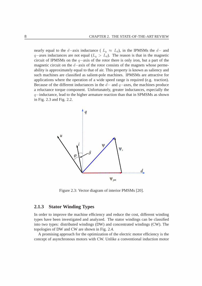
nearly equal to thed−axis inductance (Lq ≈ Ld), in the IPMSMs thed− andq−axes inductances are not equal (Lq > Ld). The reason is that in the magneticcircuit of IPMSMs on theq−axis of the rotor there is only iron, but a part of themagnetic circuit on thed−axis of the rotor consists of the magnets whose perme-ability is approximately equal to that of air. This propertyis known as saliency andsuch machines are classified as salient-pole machines. IPMSMs are attractive forapplications where the operation of a wide speed range is required (e.g. traction).Because of the different inductances in thed− andq−axes, the machines producea reluctance torque component. Unfortunately, greater inductances, especially theq−inductance, lead to the higher armature reaction than that in SPMSMs as shownin Fig. 2.3 and Fig. 2.2.
Figure 2.3: Vector diagram of interior PMSMs [20].
2.1.3 Stator Winding Types
In order to improve the machine efficiency and reduce the cost, different windingtypes have been investigated and analyzed. The stator windings can be classifiedinto two types: distributed windings (DW) and concentratedwindings (CW). Thetopologies of DW and CW are shown in Fig. 2.4.
A promising approach for the optimization of the electric motor efficiency is theconcept of asynchronous motors with CW. Unlike a conventional induction motor
2.1. OVERVIEW OF PERMANENT MAGNET SYNCHRONOUS MACHINES 9
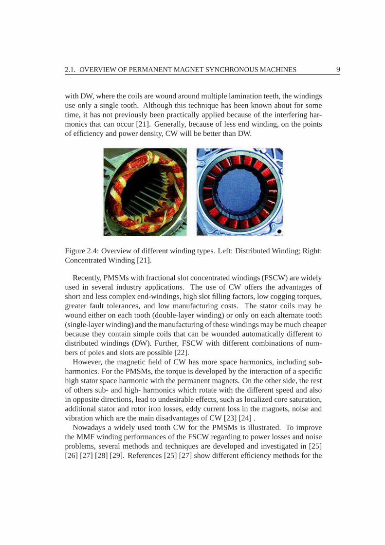
with DW, where the coils are wound around multiple lamination teeth, the windingsuse only a single tooth. Although this technique has been known about for sometime, it has not previously been practically applied because of the interfering har-monics that can occur [21]. Generally, because of less end winding, on the pointsof efficiency and power density, CW will be better than DW.
Figure 2.4: Overview of different winding types. Left: Distributed Winding; Right:Concentrated Winding [21].
Recently, PMSMs with fractional slot concentrated windings (FSCW) are widelyused in several industry applications. The use of CW offers the advantages ofshort and less complex end-windings, high slot filling factors, low cogging torques,greater fault tolerances, and low manufacturing costs. Thestator coils may bewound either on each tooth (double-layer winding) or only oneach alternate tooth(single-layer winding) and the manufacturing of these windings may be much cheaperbecause they contain simple coils that can be wounded automatically different todistributed windings (DW). Further, FSCW with different combinations of num-bers of poles and slots are possible [22].
However, the magnetic field of CW has more space harmonics, including sub-harmonics. For the PMSMs, the torque is developed by the interaction of a specifichigh stator space harmonic with the permanent magnets. On the other side, the restof others sub- and high- harmonics which rotate with the different speed and alsoin opposite directions, lead to undesirable effects, such as localized core saturation,additional stator and rotor iron losses, eddy current loss in the magnets, noise andvibration which are the main disadvantages of CW [23] [24] .
Nowadays a widely used tooth CW for the PMSMs is illustrated.To improvethe MMF winding performances of the FSCW regarding to power losses and noiseproblems, several methods and techniques are developed andinvestigated in [25][26] [27] [28] [29]. References [25] [27] show different efficiency methods for the
10 CHAPTER 2. THE STATE-OF-THE-ART REVIEW
reduction of winding sub-harmonics such as using winding coils with different turnsper coil-side or using magnetic flux barriers in the specific stator core locations.However, another new solution for reduction simultaneously the sub- and high-MMF harmonics of the FSCW is presented in [26]. An alternative technique forreduction simultaneously the sub- and high- MMF harmonics is presented in [30].
2.2 Traditional Control Strategies
In industry, the field-oriented control (FOC) and direct torque control (DTC) arethe two most widely used control strategies for AC drives. Until now, both controlmethods can provide good dynamic control performance of airgap torque, which isusually the primary input to the process or system that the motor is driving.
2.2.1 Field-Oriented Control
Vector control of AC drives was raised up in the early 1970s, which has epoch -making meaning to the industry in the beginning mainly for induction machines.In order to improve the performance of machine control, it ischaracterized by asmooth rotation over the entire speed range of the machine, full torque control atzero speed, fast accelerations, and decelerations. Vectorcontrol techniques are usedfor three-phase AC motors to achieve these control objectives. The vector controltechniques are also called as field-oriented control (FOC).The basic idea of theFOC algorithm is to decompose a stator current into a magnetic field-generatingpart and a torque-generating part. Both components can be controlled separatelyafter decomposition. The structure of the motor controlleris then as simple as a DCmachine [11].
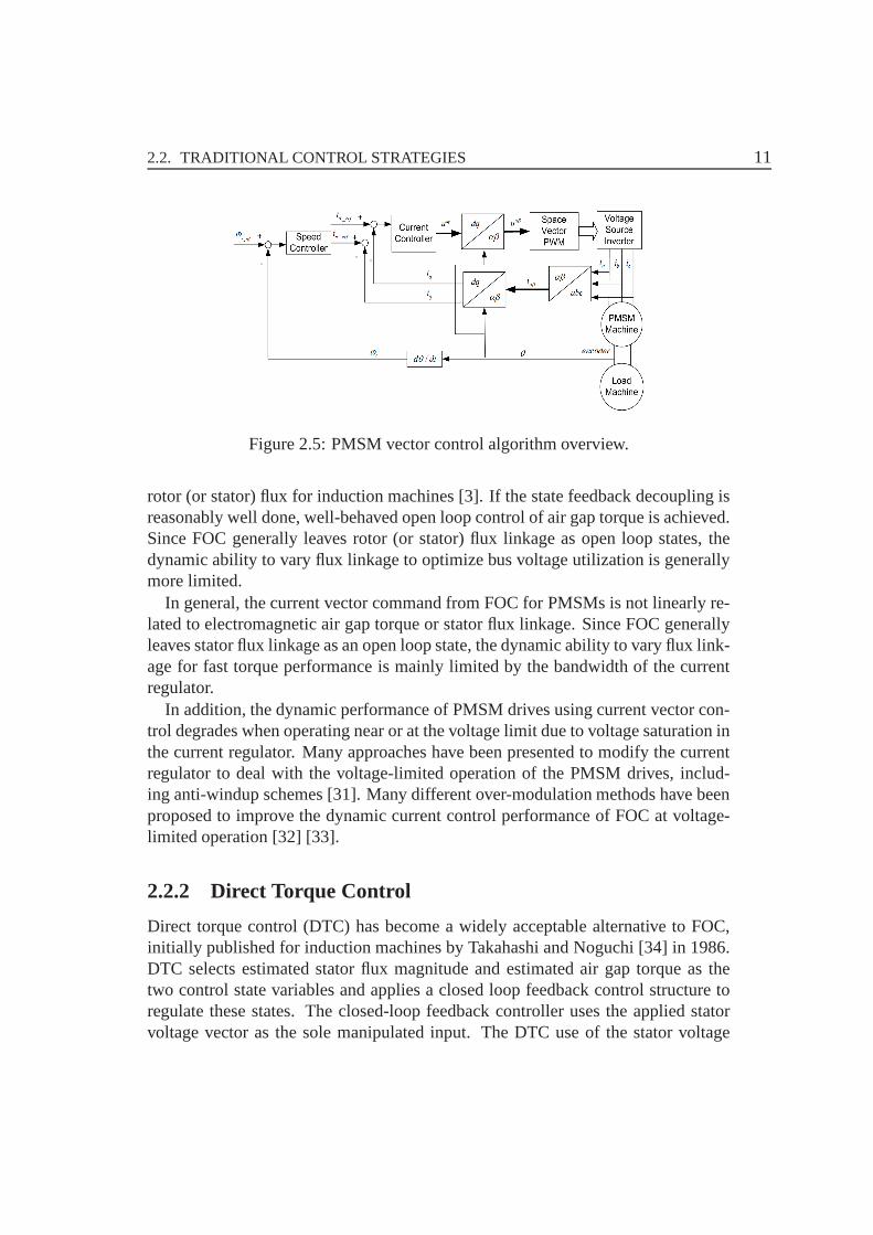
The overview block diagram of the implemented field-oriented control algorithmof PMSM is illustrated in Fig. 2.5. To achieve the high control performance ofPMSMs in real-time, the algorithm needs the feedback signals. The essential feed-back signals are three-phase stator currents. For the stator voltage, the regulatoroutput is used. For correct operation, the control structure presented requires rotorposition and speed information. The slow control loop executes the speed controllerand lower priority control tasks. The output of the PI speed controller sets aq−axiscurrent reference for the torque producing. The fast control loop is the PI currentcontroller, outputs of which are voltages in rotating reference frame.
FOC selects thed− andq−axes stator current vector components as control feed-back variables and then uses slip with the closed loop currents as ”effective” manip-ulated inputs to achieve decoupling state feedback (or feed-forward) on estimated
2.2. TRADITIONAL CONTROL STRATEGIES 11
Figure 2.5: PMSM vector control algorithm overview.
rotor (or stator) flux for induction machines [3]. If the state feedback decoupling isreasonably well done, well-behaved open loop control of airgap torque is achieved.Since FOC generally leaves rotor (or stator) flux linkage as open loop states, thedynamic ability to vary flux linkage to optimize bus voltage utilization is generallymore limited.
In general, the current vector command from FOC for PMSMs is not linearly re-lated to electromagnetic air gap torque or stator flux linkage. Since FOC generallyleaves stator flux linkage as an open loop state, the dynamic ability to vary flux link-age for fast torque performance is mainly limited by the bandwidth of the currentregulator.
In addition, the dynamic performance of PMSM drives using current vector con-trol degrades when operating near or at the voltage limit dueto voltage saturation inthe current regulator. Many approaches have been presentedto modify the currentregulator to deal with the voltage-limited operation of thePMSM drives, includ-ing anti-windup schemes [31]. Many different over-modulation methods have beenproposed to improve the dynamic current control performance of FOC at voltage-limited operation [32] [33].
2.2.2 Direct Torque Control
Direct torque control (DTC) has become a widely acceptable alternative to FOC,initially published for induction machines by Takahashi and Noguchi [34] in 1986.DTC selects estimated stator flux magnitude and estimated air gap torque as thetwo control state variables and applies a closed loop feedback control structure toregulate these states. The closed-loop feedback controller uses the applied statorvoltage vector as the sole manipulated input. The DTC use of the stator voltage
12 CHAPTER 2. THE STATE-OF-THE-ART REVIEW
vector as its manipulated input is advantageous since it is the only actual physicalmanipulated input in the system.
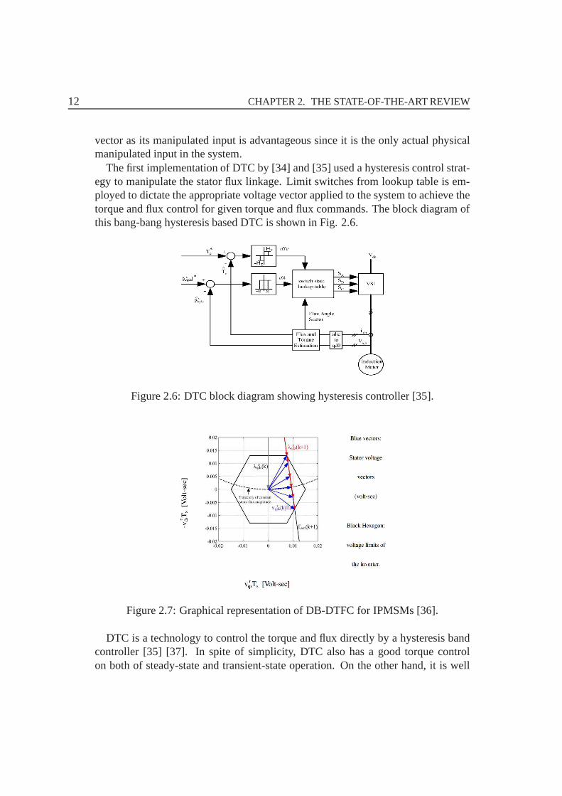
The first implementation of DTC by [34] and [35] used a hysteresis control strat-egy to manipulate the stator flux linkage. Limit switches from lookup table is em-ployed to dictate the appropriate voltage vector applied tothe system to achieve thetorque and flux control for given torque and flux commands. Theblock diagram ofthis bang-bang hysteresis based DTC is shown in Fig. 2.6.
Figure 2.6: DTC block diagram showing hysteresis controller [35].
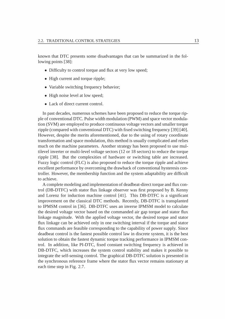
Figure 2.7: Graphical representation of DB-DTFC for IPMSMs[36].
DTC is a technology to control the torque and flux directly by ahysteresis bandcontroller [35] [37]. In spite of simplicity, DTC also has a good torque controlon both of steady-state and transient-state operation. On the other hand, it is well
2.2. TRADITIONAL CONTROL STRATEGIES 13
known that DTC presents some disadvantages that can be summarized in the fol-lowing points [38]:
• Difficulty to control torque and flux at very low speed;
• High current and torque ripple;
• Variable switching frequency behavior;
• High noise level at low speed;
• Lack of direct current control.
In past decades, numerous schemes have been proposed to reduce the torque rip-ple of conventional DTC. Pulse width modulation (PWM) and space vector modula-tion (SVM) are employed to produce continuous voltage vectors and smaller torqueripple (compared with conventional DTC) with fixed switching frequency [39] [40].However, despite the merits aforementioned, due to the using of rotary coordinatetransformation and space modulation, this method is usually complicated and reliesmuch on the machine parameters. Another strategy has been proposed to use mul-tilevel inverter or multi-level voltage sectors (12 or 18 sectors) to reduce the torqueripple [38]. But the complexities of hardware or switching table are increased.Fuzzy logic control (FLC) is also proposed to reduce the torque ripple and achieveexcellent performance by overcoming the drawback of conventional hysteresis con-troller. However, the membership function and the system adaptability are difficultto achieve.
A complete modeling and implementation of deadbeat-directtorque and flux con-trol (DB-DTFC) with stator flux linkage observer was first proposed by B. Kennyand Lorenz for induction machine control [41]. This DB-DTFCis a significantimprovement on the classical DTC methods. Recently, DB-DTFC is transplantedto IPMSM control in [36]. DB-DTFC uses an inverse IPMSM modelto calculatethe desired voltage vector based on the commanded air gap torque and stator fluxlinkage magnitude. With the applied voltage vector, the desired torque and statorflux linkage can be achieved only in one switching interval ifthe torque and statorflux commands are feasible corresponding to the capability of power supply. Sincedeadbeat control is the fastest possible control law in discrete system, it is the bestsolution to obtain the fastest dynamic torque tracking performance in IPMSM con-trol. In addition, like PI-DTC, fixed constant switching frequency is achieved inDB-DTFC, which increases the system control stability and makes it possible tointegrate the self-sensing control. The graphical DB-DTFCsolution is presented inthe synchronous reference frame where the stator flux vectorremains stationary ateach time step in Fig. 2.7.
14 CHAPTER 2. THE STATE-OF-THE-ART REVIEW
2.3 Self-sensing Control
In the high quality control system of electric drives, thereis a mechanical sensor inthe rotor of the electric machine to measure the position andspeed. There are manyproblems related to the mechanical sensor in the real application, such as the highcost of the high accuracy and quick response sensor, the error with the actual rotorposition when the concentrically problem appears after theinstallation of the sen-sor, the reliability of the system is reduced by using the sensor and so on. In orderto reduce the cost and improve the robustness of the drive system, the mechanicalsensors (tachometers, position encoders) need to remove from the control systemof electric drives. In large-scale production, the absenceof the position sensor im-plies a worthwhile cost reduction. In addition, the presence of a position sensorrepresents a possible source of fault. This is not desirablein applications like trans-portation systems and electrical vehicles, in which a high grade of fault immunityis required.
Self-sensing control of PMSMs is known since 1990s and has became popularsince the first decade of this century. The modern self-sensing control methods forPMSMs can be divided into two categories: the first one is based on back elec-tromotive force (back EMF) information [8] [9] [10] and the mathematical modelsof PMSMs using state observers; the second one is based on tracking of position-dependent spatial saliency using high-frequency(HF) injection [14] [15] [42].
2.3.1 Back-Electromotive Force and State Observers
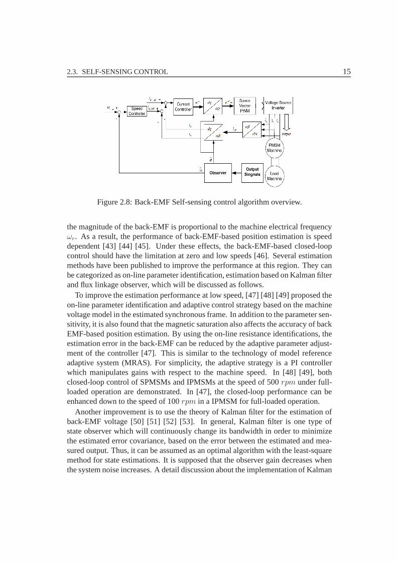
Within the last decades, several improvements have been made in the technologyof closed-loop self-sensing control. The basis of back-electromotive force (back-EMF) for self-sensing control methods are based on the integration of the machineback-EMF to estimate the flux position [9] [10]. The overviewblock diagram ofthe implemented self-sensing control algorithm of PMSM is illustrated in Fig. 2.8.The position information in back-EMF can be extracted from the voltage equation2.1 of the machine in stationary reference frame.
us = Rsis +d
dt(Lsis) + jωrΨpm (2.1)
whereΨpm = ψpmejθ, andjωrΨpm is called the back-EMF including the position
information .It is noteworthy that the parameters of resistance and inductance have to been
known in order to estimate the position of the PM flux linkage,Ψpm. This impliesthat the flux estimation accuracy is dependent on these two parameters. In addition,
2.3. SELF-SENSING CONTROL 15
Figure 2.8: Back-EMF Self-sensing control algorithm overview.
the magnitude of the back-EMF is proportional to the machineelectrical frequencyωr. As a result, the performance of back-EMF-based position estimation is speeddependent [43] [44] [45]. Under these effects, the back-EMF-based closed-loopcontrol should have the limitation at zero and low speeds [46]. Several estimationmethods have been published to improve the performance at this region. They canbe categorized as on-line parameter identification, estimation based on Kalman filterand flux linkage observer, which will be discussed as follows.
To improve the estimation performance at low speed, [47] [48] [49] proposed theon-line parameter identification and adaptive control strategy based on the machinevoltage model in the estimated synchronous frame. In addition to the parameter sen-sitivity, it is also found that the magnetic saturation alsoaffects the accuracy of backEMF-based position estimation. By using the on-line resistance identifications, theestimation error in the back-EMF can be reduced by the adaptive parameter adjust-ment of the controller [47]. This is similar to the technology of model referenceadaptive system (MRAS). For simplicity, the adaptive strategy is a PI controllerwhich manipulates gains with respect to the machine speed. In [48] [49], bothclosed-loop control of SPMSMs and IPMSMs at the speed of 500rpm under full-loaded operation are demonstrated. In [47], the closed-loop performance can beenhanced down to the speed of 100rpm in a IPMSM for full-loaded operation.
Another improvement is to use the theory of Kalman filter for the estimation ofback-EMF voltage [50] [51] [52] [53]. In general, Kalman filter is one type ofstate observer which will continuously change its bandwidth in order to minimizethe estimated error covariance, based on the error between the estimated and mea-sured output. Thus, it can be assumed as an optimal algorithmwith the least-squaremethod for state estimations. It is supposed that the observer gain decreases whenthe system noise increases. A detail discussion about the implementation of Kalman
16 CHAPTER 2. THE STATE-OF-THE-ART REVIEW
filter can be found in [50]. Some limitations on position estimation at low speed arealso mentioned. The important caveat for using Kalman filteris the selection ofthe coefficients to achieve the optimal estimation performance. It is essential tocombine the Kalman filter with some on-line system identification techniques todemonstrate the most effective mode in the back-EMF-based closed-loop system.
The position estimation based on the flux linkage observer has been demonstratedthe improved performance at low speeds. Because the flux linkage does not changewith respect to the speed, the low speed estimation performance can be improvedcomparing to the conventional back EMF estimation technique [54] [55] [56]. How-ever, this technique still has the limitation at very low speed. In [54], a SPMSMclosed-loop control was limited to speeds greater than 10rpm. Although a non-linear flux observer is developed, zero speed closed-loop control still cannot beachieved. The flux estimation technique can have better performance in IPMSMsdrives. In [55] [56], the zero and low speed closed-loop control is achieved in anIPMSM. The resistance estimation and decoupling are the keypoints for low speedclosed-loop control using flux linkage observer. However, resistance decoupling atzero and low speed is more difficult in SPMSMs because the resistance componentis primarily dominant since the inductance component is quite low. It can be seenthat the estimation of flux linkage can have the deterministic impact on the positionestimation. When the speed is sufficient high, the flux observer can precisely pre-dict the flux property because the back EMF is sufficient high.In contrast to lowspeed operation, the current model can be included to improve the flux estimationaccuracy [57] [58].
However, since the amplitude of back EMF is proportional to the rotor speed, itfails in the very low-speed region. The small or zero back-EMF voltage will haveserious effects on the accuracy of the estimated rotor position. In summary of theback-EMF-based estimation method, it can achieve better estimation performanceat the medium and high speed range.
2.3.2 High-Frequency Injection Control
Further researchers have found that the machine anisotropic properties provide ad-ditional information on the field angle or the position of therotor. This inherentproperty makes it possible to use transient excitations by injected signals havingother frequencies than the fundamental. HF injection self-sensing control showsgood rotor position estimation results at low speed and zerospeed. Unlike back-EMF estimation techniques, the injection-based saliency-tracking techniques usemachine spatial saliencies for the position estimation. Recently, it appears morepopular because of the capability to overcome the limitation of closed-loop control
2.3. SELF-SENSING CONTROL 17
at low speed.
A. Rotating Vector Injection
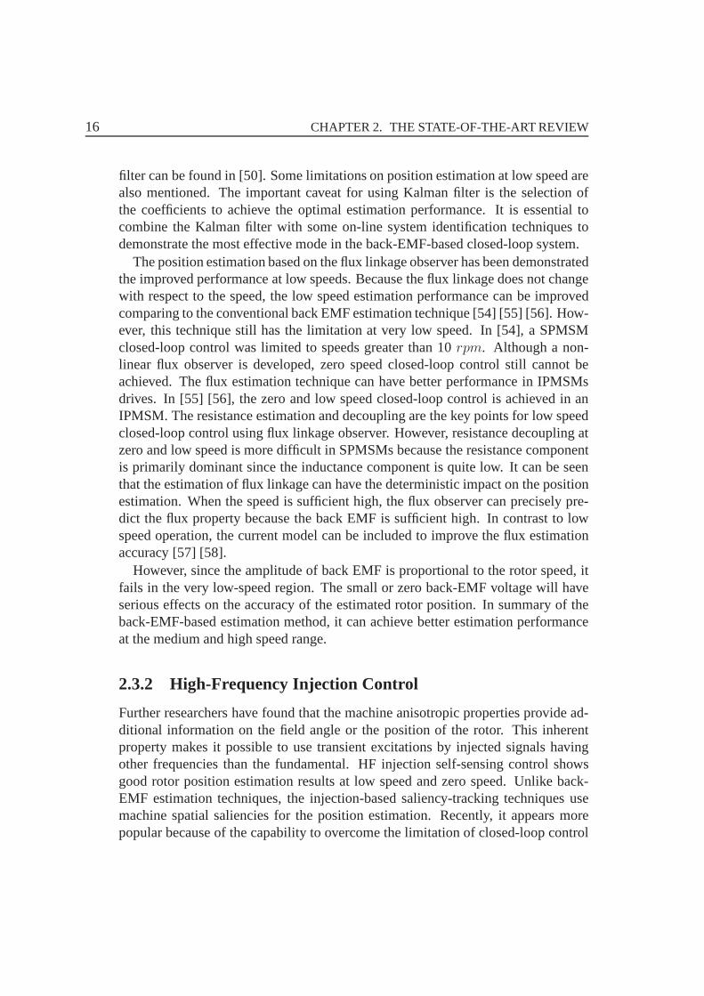
The trajectory of carrier stator currentisc with rotating vector carrier voltage signalinjection of PMSMs is shown in Fig. 2.10 which is a ellipse. Itis difficult to get theposition information from the ellipse directly. The proportion between the long andminor axes of the ellipse isLq /Ld. If the value is approaching to 1, the ovality is lowand it is very difficult to realize the position extraction. Therefore, the modulationmethod is used to recover the position information from the carrier stator currentisc.
Figure 2.9: The trajectory of carrier stator currentisc .
Rotating vector carrier voltage signal injection of PMSMs have first been reportedin [59] [60] [61]. These present a new standstill rotor position detecting algorithmfor PMSMs without any position sensor. By injecting high frequency current to thestator of the machine, the proposed algorithm provides the standstill rotor positionwith reasonable accuracy as well as the direction of magnetization.
The position information in the spatial saliency can be extracted by measuringeither negative sequence current [62] [63] [64] [14] [15] [65] or neutral voltage [66][16]. For the negative current measurement, the estimationsignal processing can
18 CHAPTER 2. THE STATE-OF-THE-ART REVIEW
be classified intoarctan current calculation [67], current peak value detection [65],phase locked loop (PLL) state filter and tracking observer [62] [63] [64] [14] [15].
Kim et. al [68] compare different estimation methods for theself-sensing con-trol. It is concluded that botharctan calculation and current peak value detectionare sensitive to noise unless an extensive low-pass filter isapplied after the esti-mated signals. The performance of state filter and tracking observer are all basedon the vector cross-product. The main difference between them is that the trackingobserver included a mechanical model including an estimated moment of inertiaand the command feed-forward (CFF) of estimated torque. As aresult, the trackingobserver can provide the parameter insensitive zero phase lag tracking performancewithin the observer bandwidth, and the parameter sensitivezero phase lag trackingbeyond its bandwidth. However, it is not possible to achievethis lag tracking in thestate filter.
B. Pulsating Vector Injection
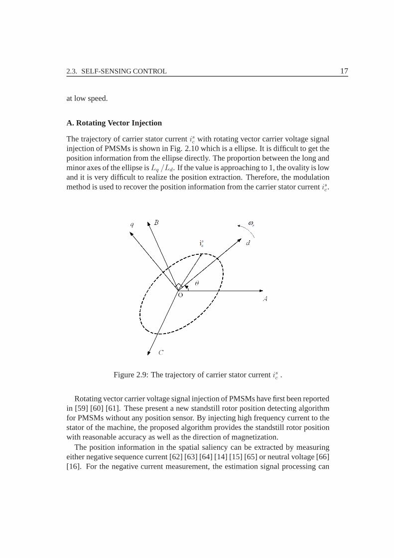
Pulsating vector carrier voltage injection is firstly proposed by Corley and Lorenz in1998 [12]. Instead of a constant amplitude rotating in the stationary frame (rotatingvector injection), a pulsating vector superimposes an amplitude-modulated voltageor current in the estimatedd− or q−axis synchronous frame is illustrated in Fig.2.10. dq means the rotor position estimation axes.
Figure 2.10: Pulsating voltage injection algorithm overview.
2.4. MODEL PREDICTIVE CONTROL 19
Since the pulsating vector voltage can be injected either inrotor d− or q−axis, itis interesting to investigate the estimation performance in both of them. Ford−axisvoltage injection, it can produce less torque ripple because the carrier vector doesnot contribute to any torque production [69]. The same authors have also proposeda two-step injection process for the purpose of polarity identification [70]. It isconcluded thatd−axis injection can be better to preserve power conversion perfor-mance.
However, theq−axis pulsating injection has been found to have a unique ad-vantage for reducing the inverter dead-time harmonics because the inducedd−axiscurrent must be zero at the steady state. In other words, the challenge of invertercompensation, parasitically capacitor charging and discharging [71], and zero cur-rent clamping [72] as phase currents cross the zero, is avoided if the injection angleis perpendicular to the magnetic axis of the machine [73]. A switching injectionmethod betweend− and q−axes based on the operating condition has been pro-posed by [74]. This injection strategy is suitable for SPMSMs, in which thed−axisfundamental current is always zero.
Very recently, a new signal injection method based on the voltage type of squarewave has been simultaneously proposed by [75] [76] and [73].The authors claimthat no low-pass filter is required by using a very high frequency (5 kHz) squarewave voltage injection to successfully separate the fundamental and carrier compo-nents. Especially in [76], the speed controller bandwidth can be enhanced to 50 Hzin a IPMSM drive using the proposed square-wave voltage injection.
2.4 Model Predictive Control
Although PMSM has many advantages like high torque density,high efficiency andso on, it still has many problems in drive system for example coupling, nonlinearand time-varying of parameters and so on. Thus the traditional methods cannotget the expected control performance. The modern control strategies are the newdeveloping directions.
Cascaded control is the state of the art in power electronicsand drives since sev-eral decades. It is not possible to expect serious changes within a short time, be-cause cascaded control is easy to realize, easy to implementand robust in operation.Furthermore industry seems to be satisfied with the performance of cascaded con-trol there is no strong pressure to improve performance fromthat side. There are,however, serious drawbacks of cascaded control: its linearconcept, the need of anextremely fast operating inner loop, etc. Academics shouldlook out for a better con-cept to have it available, when the demand for better performing control schemes
20 CHAPTER 2. THE STATE-OF-THE-ART REVIEW
occurs again from industry. Conventional DTC has an obviousdisadvantage: thetorque ripple is considerable. To tackle this drawbacks, many research efforts havebeen performed.
Predictive control methods are developed to improve the performance of the drivesystem. Predictive control is a very wide class of controllers that have found ratherrecent application in the control of power converters and drive systems. Researchon this topic has been increased in the last years due to the possibilities of today’smicroprocessors used for the control.
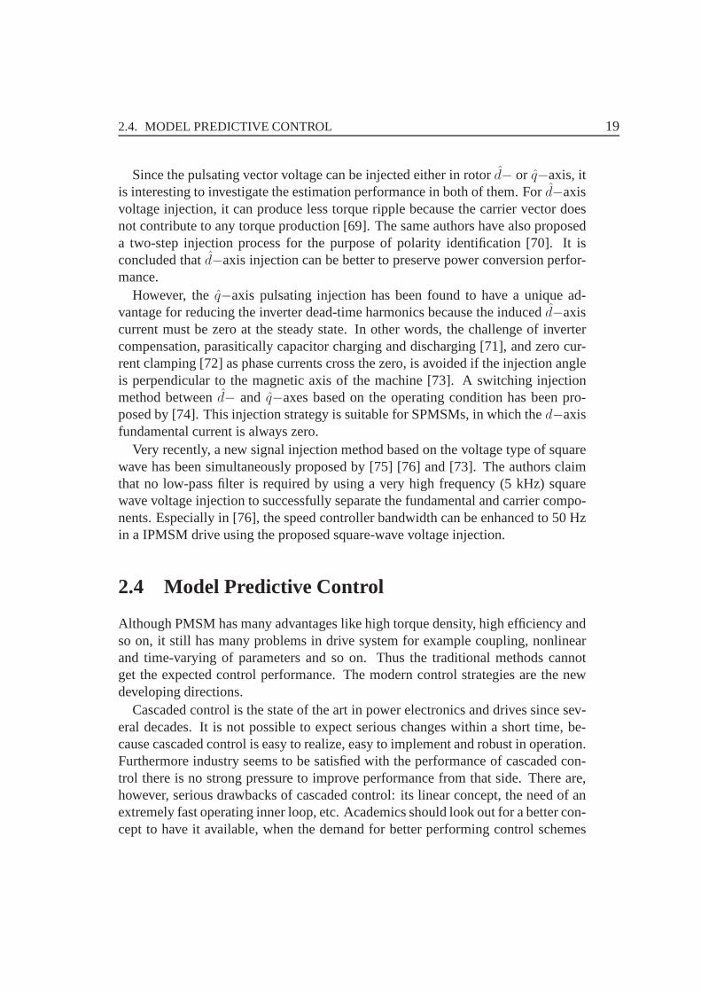
Model predictive control (MPC) is an alternative optimization and predictive con-trol strategy. It is widely used in the industry communitiesboth for electric drivesand power electronics, because it’s easy to do implementation [77] [78]. The MPCtechniques normally have been classified into two main categories: MPC with con-tinuous control set and MPC with finite control set (FCS-MPC)[79]. The MPC withcontinuous control set can avoid the cascaded control and provides fixed switch-ing frequency, but the pulse width modulation (PWM) or spacevector modulationis still needed. The FCS-MPC utilizes the inherent discretenature of the powerconverter without modulator to solve the optimization problem using a single costfunction, and has variable switching frequency. The MPC scheme is described asFig. 2.12.
Figure 2.11: Model predictive control scheme [79].
MPC also referred to as receding horizon control, is the one among the so-calledadvanced control techniques (usually understood as techniques more advanced thana standard PID control) which has been extremely successfulin practical appli-cations in recent decades, exerting a great influence on research and developmentdirections of industrial control systems. Applications and theoretical results are inthe books [77] [80] [81] and survey papers [82] [83] [84] [85]. An attractive featureof MPC is that it can handle general constrained nonlinear systems with multiple
2.5. LOSS MINIMIZATION CONTROL 21
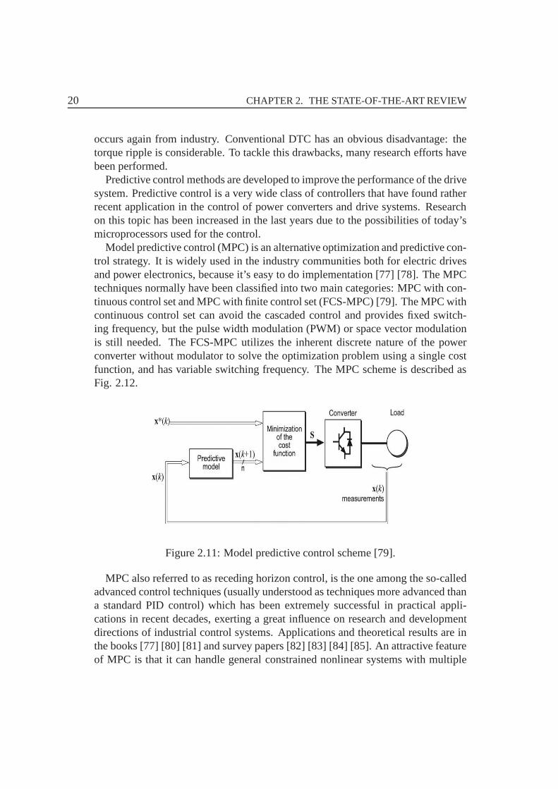
inputs and outputs in a unified and clear manner. Consideringall the possible com-binations of switching functions, seven distinct voltage vectors are obtained. Theseare shown in Fig. 2.12.
Figure 2.12: Voltage vectors generated by the voltage source inverter.
2.5 Loss Minimization Control
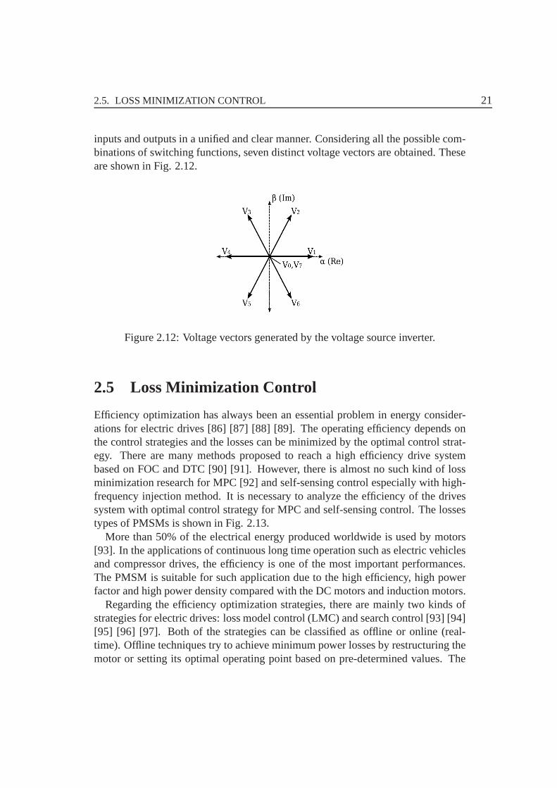
Efficiency optimization has always been an essential problem in energy consider-ations for electric drives [86] [87] [88] [89]. The operating efficiency depends onthe control strategies and the losses can be minimized by theoptimal control strat-egy. There are many methods proposed to reach a high efficiency drive systembased on FOC and DTC [90] [91]. However, there is almost no such kind of lossminimization research for MPC [92] and self-sensing control especially with high-frequency injection method. It is necessary to analyze the efficiency of the drivessystem with optimal control strategy for MPC and self-sensing control. The lossestypes of PMSMs is shown in Fig. 2.13.
More than 50% of the electrical energy produced worldwide isused by motors[93]. In the applications of continuous long time operationsuch as electric vehiclesand compressor drives, the efficiency is one of the most important performances.The PMSM is suitable for such application due to the high efficiency, high powerfactor and high power density compared with the DC motors andinduction motors.
Regarding the efficiency optimization strategies, there are mainly two kinds ofstrategies for electric drives: loss model control (LMC) and search control [93] [94][95] [96] [97]. Both of the strategies can be classified as offline or online (real-time). Offline techniques try to achieve minimum power losses by restructuring themotor or setting its optimal operating point based on pre-determined values. The
22 CHAPTER 2. THE STATE-OF-THE-ART REVIEW
Figure 2.13: The losses types of PMSMs.
drawback of offline techniques is that the losses or the loss model cannot be affectedany more by the loss minimization techniques while the motoris running, unless themotor is stopped, restructured, or the operating point is reset. The difference is thatthe loss model of LMC is only built according to machine parameters, while theloss model of SC also takes into account the losses of the power electronics.
The principle of LMC is that an accurate machine model shouldbe built andit includes the machine losses over the full operating speedrange. Based on thespeed and current signals, the minimum losses can be achieved by using optimalarmature current or optimal flux linkage. Based on LMC method, the machineparameters are nearly known, thus the accuracy of the iron loss and PM loss becomea key point of the accuracy of LMC. In [95] [97] the authors model the iron loss ofelectrical machines, predict and analyze the possible parameters of iron loss, butfinally it do not give a clear and fixed strategy for optimizingiron loss. Reference[93] introduces an optimization method to get the optimald− axis current basedon vector control strategy. However, it does not introduce how to get the accurateresistanceRFe parameter for the iron loss in order to fix at the rated operation.Some researchers analyze the iron loss and PM loss based on finite element method(FEM). However, most of them do not take into account the influence of controlstrategies.
The loss minimization control can be combined with the modern control strate-gies such as MPC and self-sensing control. For example, the self-sensing controlmethod based on the HF injection, there are some extra lossesdue to the injectionsignals. The losses resulting from the HF injection are needed to be analyzed. It isdifficult to find a loss minimization control algorithm for HFinjection-based self-

2.5. LOSS MINIMIZATION CONTROL 23
sensing control scheme directly. The best way is to analyze the additional losses inthe machines, in order to find a balance between the cost of theposition encoderand the extra losses consumption.

24 CHAPTER 2. THE STATE-OF-THE-ART REVIEW

25
CHAPTER 3
Self-sensing Control of SPMSMs Based on DifferentHigh-Frequency Injection Methods
The magnetic and mechanical design of the PMSMs has impact onthe performanceof self-sensing control with HF injection [13]. The surface-mounted PMSMs do nothave the saliency phenomena in the structure compared with the interior PMSMs.The experimental results of the SPMSM presented in this chapter show the self-sensing control scheme having no limitations with respect to a minimal speed; thedrive is able to provide full torque in self-sensing operation even at standstill. Thecontrol behavior of position and speed control is equal to a servo drive with resolverfeedback. Future developments and possibilities will be discussed.
3.1 Mathematical Model of PMSMs
In order to build the mathematic model of PMSMs, the presumptions are shown asfollowing:
• The positive direction of electromotive force (EMF) and thepositive directionof the current is opposite;
• The positive direction of the speed and electromagnetic torque is the counter-clockwise direction;
• Ignoring of the iron saturation effects and the eddy current& hysteresis losses;
• The conductivity of the permanent magnet is zero;
• There is no amortisseur winding in the rotor;
26CHAPTER 3. SELF-SENSING CONTROL OF SPMSMS BASED ON DIFFERENT
HIGH-FREQUENCY INJECTION METHODS
• The electromotive force (EMF) of phase winding is sinusoidal [1].
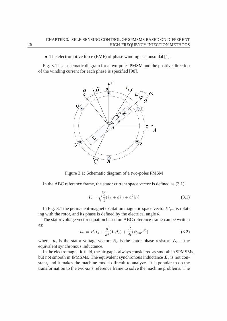
Fig. 3.1 is a schematic diagram for a two-poles PMSM and the positive directionof the winding current for each phase is specified [98].
Figure 3.1: Schematic diagram of a two-poles PMSM
In the ABC reference frame, the stator current space vector is defined as (3.1).
is =
√2
3(iA + aiB + a2iC) (3.1)
In Fig. 3.1 the permanent-magnet excitation magnetic spacevectorΨpm is rotat-ing with the rotor, and its phase is defined by the electrical angleθ.
The stator voltage vector equation based on ABC reference frame can be writtenas:
us = Rsis +d
dt(Lsis) +
d
dt(ψpme
jθ) (3.2)
where,us is the stator voltage vector;Rs is the stator phase resistor;Ls is theequivalent synchronous inductance.
In the electromagnetic field, the air-gap is always considered as smooth in SPMSMs,but not smooth in IPMSMs. The equivalent synchronous inductanceLs is not con-stant, and it makes the machine model difficult to analyze. Itis popular to do thetransformation to the two-axis reference frame to solve themachine problems. The

3.2. HIGH-FREQUENCY MODEL OF SPMSMS 27
axis of the fundamental of the permanent-magnet excitationmagnetic field is de-fined asd−axis, andq-axis has a phase lead90 to d-axis along with the directionof the rotating in Fig. 3.1. Thedq-axis reference frame can be seen as the rotatingcomplex plane, where, thed-axis is the real-axis and theq-axis is the imaginary-axis.
Transformation (3.2) to the rotor fixed direct and quadrature axis (dq-axis) resultsin (3.3).
ud = Rsid +ddtψd − ωrψq
uq = Rsiq +ddtψq + ωrψd
(3.3)
The electromagnetic torque equation of the PMSMs is shown as(3.4).
Te = PΨs × is (3.4)
where, the flux linkage and the current in thedq-axis can be expressed as (3.5).
Ψs = ψd + jψq
is = id + jiq(3.5)
Substituting (3.5) into (3.4), the electromagnetic torqueequation in thedq-axisresult in (3.6).
Te = P [ψdiq − ψqid] (3.6)
The mechanical equation of the PMSMs is (3.7).
Te − TL = Jdωm
dt+Rωm (3.7)
3.2 High-Frequency Model of SPMSMs
Compared with the salient-pole PMSMs, the SPMSMs do not havethe saliencyphenomena in the structure. When under the main flux path saturation condition,SPMSMs have the saliency phenomena effects. It is importantto point out that satu-ration saliency is also exist in IPMSMs, but for SPMSMs thereis only the saturationsaliency in the mostly conditions [61] [98].
In thedq-axis reference frame as shown in Fig. 3.1, the flux leakage function canbe described as following:
ψd = Ldid + ψpm
ψq = Lqiq(3.8)
28CHAPTER 3. SELF-SENSING CONTROL OF SPMSMS BASED ON DIFFERENT
HIGH-FREQUENCY INJECTION METHODS
There is a permanent-magnet excitation magnetic field vector Ψpm in thed−axisdirection. If this magnetic field is big enough, the magneticflux path in thed−axiswill have saturation. When the machine is under load condition, due to the super-imposing of the armature magnetic field, the saturation of the d−axis will increaseor decrease.ψpm can be described as:
ψpm = Lmdif (3.9)
whereLmd is the excited inductance of the d-axis main magnetic flux path; if is theequivalent excited current.
Substituting (3.9) into (3.8), the flux linkage ofd−axis can be rewritten as:
ψd = (Lmd + Lsσ)id + Lmdif
= Lsσid + Lsσ(id + if)(3.10)
For the excited magnetic field of the main magnetic flux path ofthed−axis, itcan be described as:
ψmd = Lmd(id + if) (3.11)
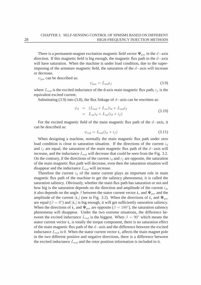
When designing a machine, normally the main magnetic flux path under zeroload condition is close to saturation situation. If the directions of the currentidandif are equal, the saturation of the main magnetic flux path of thed−axis willincrease, and the inductanceLmd will decrease that could be seen from the Fig. 3.2.On the contrary, if the directions of the currentid andif are opposite, the saturationof the main magnetic flux path will decrease, even then the saturation situation willdisappear and the inductanceLmd will increase.
Therefore the currentid of the stator current plays an important role in mainmagnetic flux path of the machine to get the saliency phenomena; it is called thesaturation saliency. Obviously, whether the main flux path has saturation or not andhow big is the saturation depends on the direction and amplitude of the currentid,it also depends on the angleβ between the stator current vectoris andΨpm and theamplitude of the current|is| (see in Fig. 3.2). When the directions ofis andΨpm
are equal (β = 0) and|is| is big enough, it will get sufficiently saturation saliency.When the directions ofis andΨpm are opposite (β = 180), the saturation saliencyphenomena will disappear. Under the two extreme situations, the difference be-tween the excited inductanceLmd is the biggest. Whenβ = 90 which means thestator current vectoris is totally the torque component, there is no saturation effectof the main magnetic flux path of thed−axis and the difference between the excitedinductanceLmd is 0. When the stator current vectoris affects the main magnet polein the two different positive and negative directions, there is a difference betweenthe excited inductanceLmd and the rotor position information is included in it.
3.3. ROTATING VECTOR INJECTION METHOD FOR SPMSMS 29
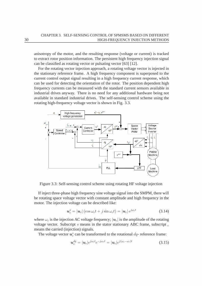
Figure 3.2: The magnetization curve of the main magnetic fluxpath of thed−axis.
The equation of the stator voltage of PMSMs based ondq− axis in fundamentalfrequency can be rewritten from (3.3):
ud = Rsid + Lddiddt
− ωrLqiq
uq = Rsiq + Lqdiqdt
+ ωrLdid + ωrψpm
(3.12)
When a HF voltage or current vector signal is injected, the carrier stator voltageequation normally ignores the resistance and the electromotive force (EMF), be-cause these are much lower than the inductance voltage for high frequencies andcan therefore be changed as:
ud = Lddiddt
uq = Lqdiqdt
(3.13)
3.3 Rotating Vector Injection Method for SPMSMs
The high-frequency injection signal (current or voltage) is superimposed on the fun-damental excitation. The applied signals interact with therotor saliency or magnetic
30CHAPTER 3. SELF-SENSING CONTROL OF SPMSMS BASED ON DIFFERENT
HIGH-FREQUENCY INJECTION METHODS
anisotropy of the motor, and the resulting response (voltage or current) is trackedto extract rotor position information. The persistent highfrequency injection signalcan be classified as rotating vector or pulsating vector [63][12].
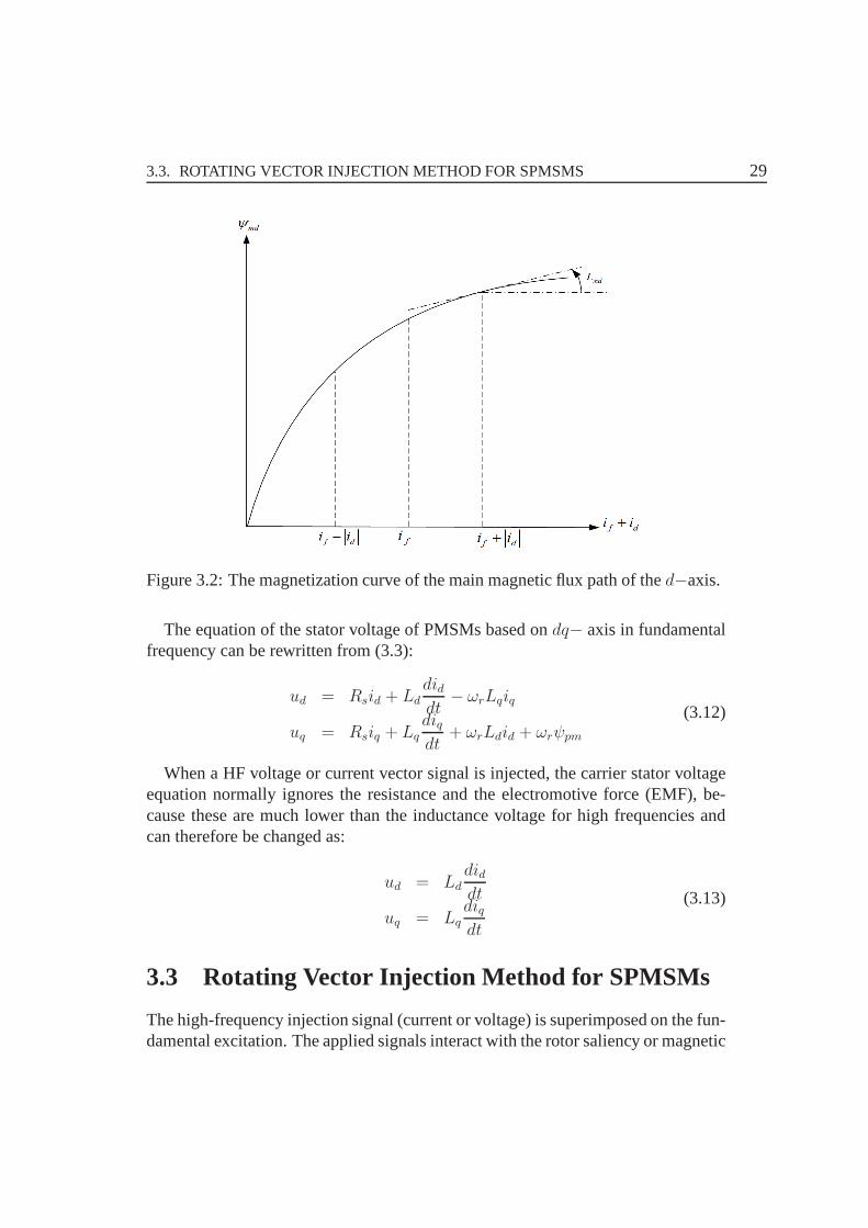
For the rotating vector injection approach, a rotating voltage vector is injected inthe stationary reference frame. A high frequency componentis superposed to thecurrent control output signal resulting in a high frequencycurrent response, whichcan be used for detecting the orientation of the rotor. The position dependent highfrequency currents can be measured with the standard current sensors available inindustrial drives anyway. There is no need for any additional hardware being notavailable in standard industrial drives. The self-sensingcontrol scheme using therotating high-frequency voltage vector is shown in Fig. 3.3.
Figure 3.3: Self-sensing control scheme using rotating HF voltage injection
If inject three-phase high frequency sine voltage signal into the SMPM, there willbe rotating space voltage vector with constant amplitude and high frequency in themotor. The injection voltage can be described like:
usc = |uc| (cosωct + j sinωct) = |uc| e
jωct (3.14)
whereωc is the injection AC voltage frequency;|uc| is the amplitude of the rotatingvoltage vector. Subscripts means in the stator stationary ABC frame, subscriptc
means the carried (injection) signals.The voltage vectorus
c can be transformed to the rotationaldq- reference frame:
udqc = |uc|e
jωcte−jωrt = |uc|ej(ωc−ωr)t (3.15)

3.3. ROTATING VECTOR INJECTION METHOD FOR SPMSMS 31
The known stator voltage (3.2) normally ignores the resistance and the electro-motive force (EMF) when a HF voltage vector signal is injected and can thereforebe changed as [14]:
us =d
dt(Lsis) (3.16)
The voltage vectorudqc can be rewritten as:
udqc = Ldq
didqcdt
(3.17)
where
Ldq =
[Ld 0
0 Lq
](3.18)
Thereforedidqcdt
= L−1dq |uc|e
j(ωc−ωr)t (3.19)
The carrier stator current indq-axis derived from (3.19) results in:
idqc =−j |uc|
ωcLdLq[1
2(Ld + Lq)e
j(ωc−ωr)t +1
2(Ld − Lq)e
−j(ωc−ωr)t] (3.20)
Transformation (3.20) to the stationary reference frame results in:
isc = idqc ejωrt (3.21)
then
isc =−j |uc|
ωcLdLq[1
2(Ld + Lq)e
jωct +1
2(Ld − Lq)e
j(−ωc+2ωr)t]
= −j |ip| ejωct − j |in| e
−j(ωct+2θ)(3.22)
where
|ip| =Ld + Lq
2LdLq
|uc|
ωc=
ΣL
ΣL2 −∆L2
|uc|
ωc
|in| =Ld − Lq
2LdLq
|uc|
ωc=
∆L
ΣL2 −∆L2
|uc|
ωc
(3.23)
ΣL = 1/2(Ld + Lq) ∆L = 1/2(Lq − Ld) (3.24)
Equation (3.23) describes that the superimposed stator current vector can be de-parted into two components: one vectorip is rotating in positive direction according

32CHAPTER 3. SELF-SENSING CONTROL OF SPMSMS BASED ON DIFFERENT
HIGH-FREQUENCY INJECTION METHODS
to the injection angular speedωc ; the other vectorin is rotating in negative direc-
tion according to the angular speed−ωc + 2ωr (ωr =dθ
dt), and the rotational speed
informationωr only is included in the vectorin [5].In order to get the estimated rotor position information, atfirst using (3.23) to
multiply ejωct will get
iscejωct = −j |ip| e
j2ωct − j |in| ej2ωrt (3.25)
The sensorless control scheme in Fig. 3.3 uses only the second term on the right-side of (3.25), because only this part includes the speed information.
The second step is using a low-pass filter (LPF) in order to extractωr from thehigh frequency carrier current. After the LPF (3.23) will bechanged as
(iscejωct)LPF = −j |in| e
j2ωrt (3.26)
The third step is using the phase-locked loop (PLL) block in Fig. 3.4 to esti-mate the speed and the rotor position information. The inputof PLL is (3.26), andmultiply with [cos 2θ sin 2θ]T will get
|in| sin(2θ − 2θ) ≈ 2 |in| θ − 2θ (3.27)
Then use the PI controller to get the estimate speed and use the integral part toget the estimated angle in the closed-loop self-sensing control system.
Figure 3.4: The PLL block
3.4 Pulsating Vector Injection Method For SPMSMs
For the rotor design of the surface-mounted PMSMs, the valueof d−axis inductanceLd andq−axis inductanceLq can be considered as unequal when the machine istested. The saliency ratio of SPMSMs is very small when the machine is undertested. The pulsating injection is carried out by superimposing a voltage or currentvector at the estimated synchronous reference frame, and itwould be robust to localsaliency [6].

3.4. PULSATING VECTOR INJECTION METHOD FOR SPMSMS 33
Figure 3.5: Pulsating voltage injection into the estimatedd−axis.
If the high frequency voltage is injected into the estimatedd−axis in thedq ref-erence frame shown as Fig.3.5, the voltage vector can be written like:
udc = Uc cos(ωct) (3.28)
where,ωc andUc is the pulsating frequency and the amplitude of the voltage,re-spectively. It can be seen in Fig.3.5, the pulsating voltagevectorud
c is located in thed−axis and its pulsating range is|po| = |oq| = Uc.
Transformation (3.28) to thedq−axis reference frame results in:
udc = Uc cos(ωct)e
j(θ−θ) (3.29)
If θ = θ, the pulsating voltage vectoruc is directly along with thed−axis andits resulting pulsating magnetic filed is added with the excited magnetic filedΨPM .Therefore it induces the saliency saturation of the excitedmagnetic flux path andresult in the modulation effects forud
c [15]. Whenuc deviates thed−axis, themodulation effects are changed and these will affect the carrier current. The positioninformation is included in the current and is derived as [74]:
idqc =Uc
ωcsinωct[
1
Ldcos(θ − θ) + j
1
Lqsin(θ − θ)] (3.30)

34CHAPTER 3. SELF-SENSING CONTROL OF SPMSMS BASED ON DIFFERENT
HIGH-FREQUENCY INJECTION METHODS
It demonstrates|idqc | the amplitude of the carrier current is connected with thepulsating voltage, frequency and the estimation error.
Transformation (3.30) to the stationary reference frame results in:
isc = idqc ejθ
=−jUc
4ωcLdLq[(Ld + Lq)e
j(ωct+θ) − (Ld − Lq)ej(ωct+θ−2γ)]
+ [−(Ld + Lq)ej(−ωct+θ) + (Ld − Lq)e
j(−ωct+θ−2γ)]
= ip + in
(3.31)
whereγ = θ − θ, ip andinis the positive and negative current component, respec-tively.
In order to get the position information, the carrier current isc need to be demod-ulated. Making the transformation, it means using (3.31) multiply e−j(ωct+θ):
ipe−j(ωct+θ) =
−jUc
4ωcLdLq
[(Ld + Lq)− (Ld − Lq)ej(2θ−2θ)] (3.32)
ine−j(ωct+θ) =
−jUc
4ωcLdLq[(Ld − Lq)e
j(−2ωct−2γ) − (Ld + Lq)ej(−2ωct)] (3.33)
Obviously the current in (3.33) is the high frequency component and can be easilyfiltered by the low pass filter (LPF). These is only the estimation error2∆θ in (3.32),where
∆θ = θ − θ (3.34)
Equation (3.32) can be rewritten as:
ipe−j(ωct+θ) =
Uc
4ωcLdLq
−(Ld−Lq) sin 2∆θ− j[(Ld+Lq)− (Ld−Lq) cos 2∆θ]
(3.35)
3.5 Implementation and Experimental Results
3.5.1 Hardware Description
The proposed self-sensing control methods have been testedon an experimental testbench. It consists of a surface-mounted permanent-magnet synchronous machineand a 2.2 kW squirrel-cage induction machine. The IM driven by a commercialLTi inverter, is used as load machine. The SPMSM is driven by amodified SEW11.2 kVA inverter which provides full control of IGBT gates.A self-made 1.4 GHz
3.5. IMPLEMENTATION AND EXPERIMENTAL RESULTS 35
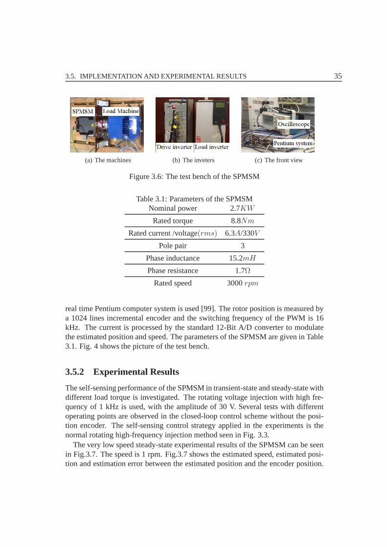
(a) The machines (b) The inveters (c) The front view
Figure 3.6: The test bench of the SPMSM
Table 3.1: Parameters of the SPMSMNominal power 2.7KW
Rated torque 8.8Nm
Rated current /voltage(rms) 6.3A/330V
Pole pair 3
Phase inductance 15.2mH
Phase resistance 1.7Ω
Rated speed 3000rpm
real time Pentium computer system is used [99]. The rotor position is measured bya 1024 lines incremental encoder and the switching frequency of the PWM is 16kHz. The current is processed by the standard 12-Bit A/D converter to modulatethe estimated position and speed. The parameters of the SPMSM are given in Table3.1. Fig. 4 shows the picture of the test bench.
3.5.2 Experimental Results
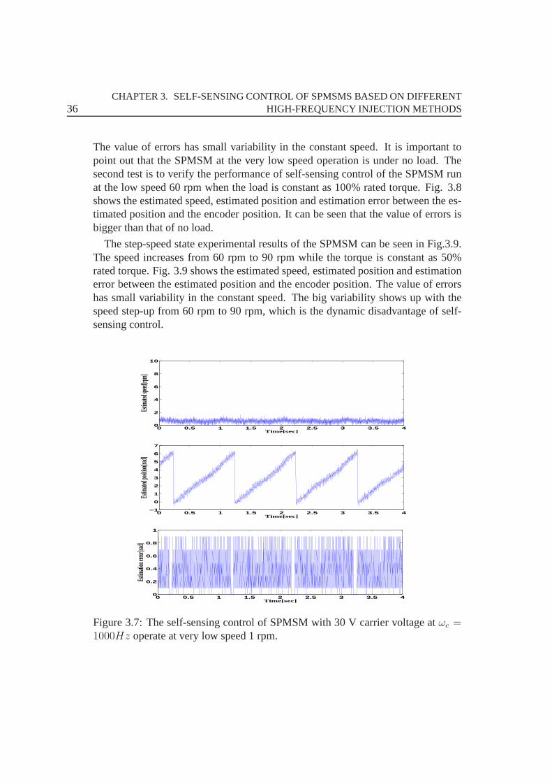
The self-sensing performance of the SPMSM in transient-state and steady-state withdifferent load torque is investigated. The rotating voltage injection with high fre-quency of 1 kHz is used, with the amplitude of 30 V. Several tests with differentoperating points are observed in the closed-loop control scheme without the posi-tion encoder. The self-sensing control strategy applied inthe experiments is thenormal rotating high-frequency injection method seen in Fig. 3.3.
The very low speed steady-state experimental results of theSPMSM can be seenin Fig.3.7. The speed is 1 rpm. Fig.3.7 shows the estimated speed, estimated posi-tion and estimation error between the estimated position and the encoder position.
36CHAPTER 3. SELF-SENSING CONTROL OF SPMSMS BASED ON DIFFERENT
HIGH-FREQUENCY INJECTION METHODS
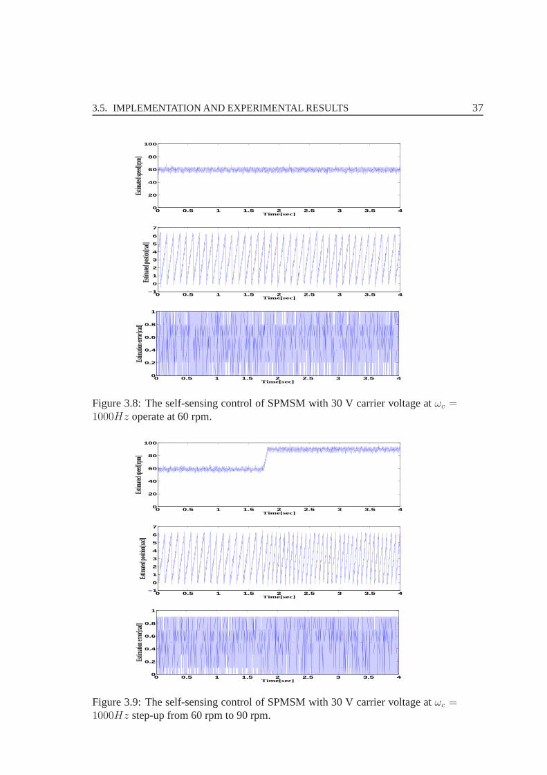
The value of errors has small variability in the constant speed. It is important topoint out that the SPMSM at the very low speed operation is under no load. Thesecond test is to verify the performance of self-sensing control of the SPMSM runat the low speed 60 rpm when the load is constant as 100% rated torque. Fig. 3.8shows the estimated speed, estimated position and estimation error between the es-timated position and the encoder position. It can be seen that the value of errors isbigger than that of no load.
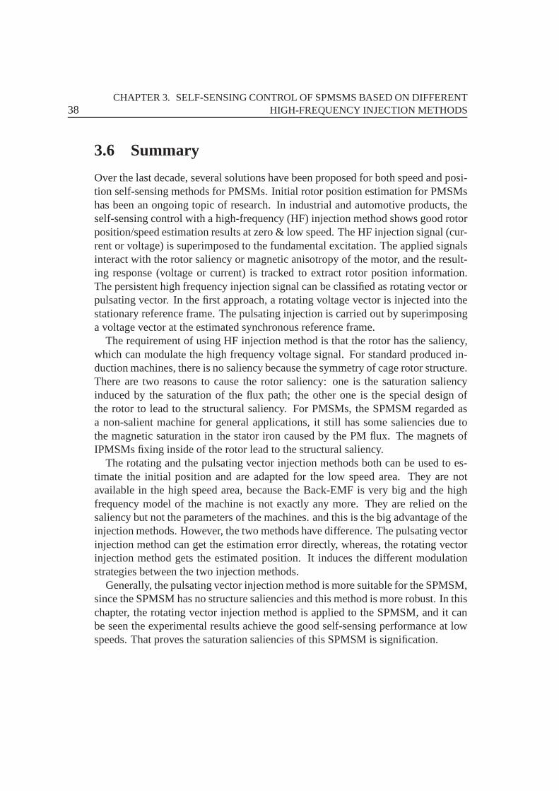
The step-speed state experimental results of the SPMSM can be seen in Fig.3.9.The speed increases from 60 rpm to 90 rpm while the torque is constant as 50%rated torque. Fig. 3.9 shows the estimated speed, estimatedposition and estimationerror between the estimated position and the encoder position. The value of errorshas small variability in the constant speed. The big variability shows up with thespeed step-up from 60 rpm to 90 rpm, which is the dynamic disadvantage of self-sensing control.
0 0.5 1 1.5 2 2.5 3 3.5 40
2
4
6
8
10
Time[sec]
Estim
ated s
peed[r
pm]
0 0.5 1 1.5 2 2.5 3 3.5 4−1
0
1
2
3
4
5
6
7
Time[sec]
Estim
ated p
osition
[rad]
0 0.5 1 1.5 2 2.5 3 3.5 40
0.2
0.4
0.6
0.8
1
Time[sec]
Estim
ation e
rror[ra
d]
Figure 3.7: The self-sensing control of SPMSM with 30 V carrier voltage atωc =1000Hz operate at very low speed 1 rpm.
3.5. IMPLEMENTATION AND EXPERIMENTAL RESULTS 37
0 0.5 1 1.5 2 2.5 3 3.5 40
20
40
60
80
100
Time[sec]
Estim
ated s
peed[r
pm]
0 0.5 1 1.5 2 2.5 3 3.5 4−1
0
1
2
3
4
5
6
7
Time[sec]
Estim
ated p
ostion
[rad]
0 0.5 1 1.5 2 2.5 3 3.5 40
0.2
0.4
0.6
0.8
1
Time[sec]
Estim
ation e
rror[ra
d]
Figure 3.8: The self-sensing control of SPMSM with 30 V carrier voltage atωc =1000Hz operate at 60 rpm.
0 0.5 1 1.5 2 2.5 3 3.5 40
20
40
60
80
100
Time[sec]
Estim
ated s
peed[r
pm]
0 0.5 1 1.5 2 2.5 3 3.5 4−1
0
1
2
3
4
5
6
7
Time[sec]
Estim
ated p
osition
[rad]
0 0.5 1 1.5 2 2.5 3 3.5 40
0.2
0.4
0.6
0.8
1
Time[sec]
Estim
ation e
rror[ra
d]
Figure 3.9: The self-sensing control of SPMSM with 30 V carrier voltage atωc =1000Hz step-up from 60 rpm to 90 rpm.
38CHAPTER 3. SELF-SENSING CONTROL OF SPMSMS BASED ON DIFFERENT
HIGH-FREQUENCY INJECTION METHODS
3.6 Summary
Over the last decade, several solutions have been proposed for both speed and posi-tion self-sensing methods for PMSMs. Initial rotor position estimation for PMSMshas been an ongoing topic of research. In industrial and automotive products, theself-sensing control with a high-frequency (HF) injectionmethod shows good rotorposition/speed estimation results at zero & low speed. The HF injection signal (cur-rent or voltage) is superimposed to the fundamental excitation. The applied signalsinteract with the rotor saliency or magnetic anisotropy of the motor, and the result-ing response (voltage or current) is tracked to extract rotor position information.The persistent high frequency injection signal can be classified as rotating vector orpulsating vector. In the first approach, a rotating voltage vector is injected into thestationary reference frame. The pulsating injection is carried out by superimposinga voltage vector at the estimated synchronous reference frame.
The requirement of using HF injection method is that the rotor has the saliency,which can modulate the high frequency voltage signal. For standard produced in-duction machines, there is no saliency because the symmetryof cage rotor structure.There are two reasons to cause the rotor saliency: one is the saturation saliencyinduced by the saturation of the flux path; the other one is thespecial design ofthe rotor to lead to the structural saliency. For PMSMs, the SPMSM regarded asa non-salient machine for general applications, it still has some saliencies due tothe magnetic saturation in the stator iron caused by the PM flux. The magnets ofIPMSMs fixing inside of the rotor lead to the structural saliency.
The rotating and the pulsating vector injection methods both can be used to es-timate the initial position and are adapted for the low speedarea. They are notavailable in the high speed area, because the Back-EMF is very big and the highfrequency model of the machine is not exactly any more. They are relied on thesaliency but not the parameters of the machines. and this is the big advantage of theinjection methods. However, the two methods have difference. The pulsating vectorinjection method can get the estimation error directly, whereas, the rotating vectorinjection method gets the estimated position. It induces the different modulationstrategies between the two injection methods.
Generally, the pulsating vector injection method is more suitable for the SPMSM,since the SPMSM has no structure saliencies and this method is more robust. In thischapter, the rotating vector injection method is applied tothe SPMSM, and it canbe seen the experimental results achieve the good self-sensing performance at lowspeeds. That proves the saturation saliencies of this SPMSMis signification.
39
CHAPTER 4
Estimation Accuracy Analysis for Injection-basedSelf-sensing Control of IPMSMs
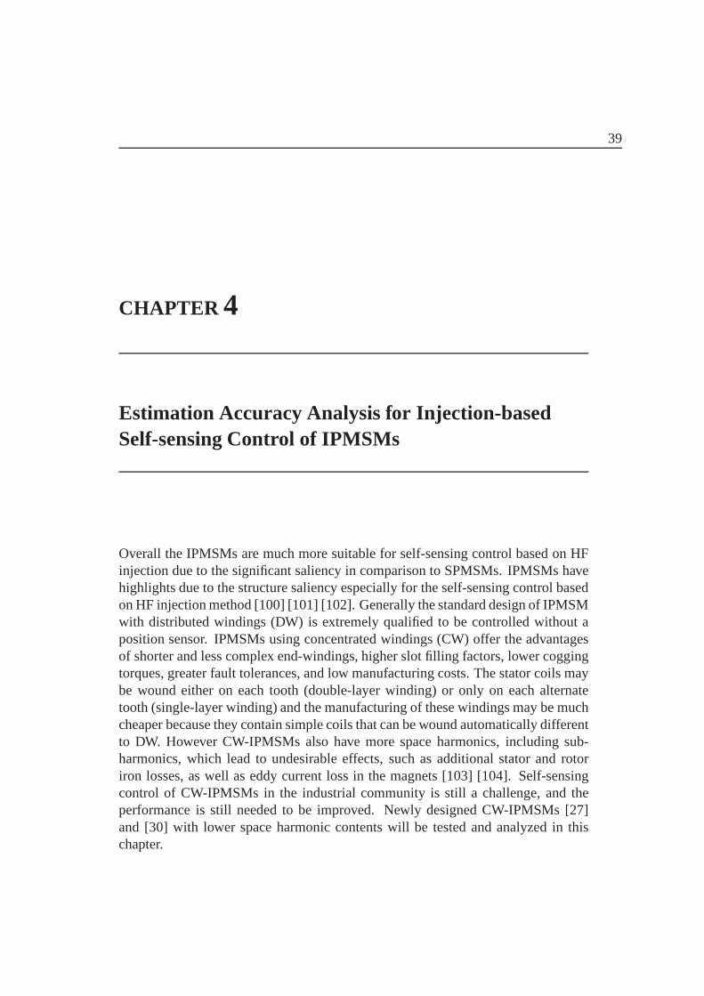
Overall the IPMSMs are much more suitable for self-sensing control based on HFinjection due to the significant saliency in comparison to SPMSMs. IPMSMs havehighlights due to the structure saliency especially for theself-sensing control basedon HF injection method [100] [101] [102]. Generally the standard design of IPMSMwith distributed windings (DW) is extremely qualified to be controlled without aposition sensor. IPMSMs using concentrated windings (CW) offer the advantagesof shorter and less complex end-windings, higher slot filling factors, lower coggingtorques, greater fault tolerances, and low manufacturing costs. The stator coils maybe wound either on each tooth (double-layer winding) or onlyon each alternatetooth (single-layer winding) and the manufacturing of these windings may be muchcheaper because they contain simple coils that can be wound automatically differentto DW. However CW-IPMSMs also have more space harmonics, including sub-harmonics, which lead to undesirable effects, such as additional stator and rotoriron losses, as well as eddy current loss in the magnets [103][104]. Self-sensingcontrol of CW-IPMSMs in the industrial community is still a challenge, and theperformance is still needed to be improved. Newly designed CW-IPMSMs [27]and [30] with lower space harmonic contents will be tested and analyzed in thischapter.
40CHAPTER 4. ESTIMATION ACCURACY ANALYSIS FOR INJECTION-BASED
SELF-SENSING CONTROL OF IPMSMS
(a) IPMSM1 (b) IPMSM2
(c) IPMSM3 (d) IPMSM-3 Star& Delta wind-ing connection
Figure 4.1: Winding layout topology of three IPMSMs
4.1 Novel CW-IPMSMs Design
Two novel designed CW-IPMSMs will be analyzed and tested in the chapter. Inorder to compare these with the conventional machines, three CW-IPMSMs withdifferent stator design are comparatively demonstrated, which are shown in the fol-lowing Table 4.1. All the three IPMSMs contain concentrateddouble-layer wind-ings, and their winding topology can be seen in Fig. 4.1. The technical parametersof the two novel CW-IPMSMs are shown in Table 4.2. The IPMSM-1without tech-nical date is only the simulation model in purpose to do the comparison.
There are many possible slot number and pole number combinations for PM ma-chines with concentrated windings.The winding layout and the winding factor of aPM machine with concentrated winding depend on its combination of pole and slot
4.1. NOVEL CW-IPMSMS DESIGN 41
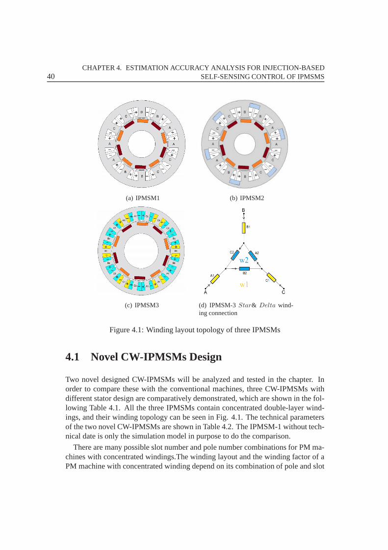
Table 4.1: Three CW-IPMSMsIPMSM1 conventional 12-teeth /10-poles
IPMSM2 novel 12-teeth /10-poles
IPMSM3 novel 18-teeth /10-poles
Table 4.2: Parameters of novel IPMSMsParameters IPMSM2 IPMSM3
Nominal power 425W 31KW
Rated torque 2Nm 200Nm
Rated current /voltage(rms) 50A/8.5V 100A/310V
Pole pair 5 5
d / q-axis inductance 0.05mH/0.095mH 0.76mH/1.168mH
Resistance 10mΩ 32mΩ
Rated/maximum speed 2000/4000rpm 4000/14000rpm
number. Therefore, this combination should be chosen carefully in order to max-imize the fundamental (magnetomotive force (MMF) working harmonic) windingfactor and minimize the eddy current losses. Single-layer windings are preferredto double-layer windings when a high fundamental winding factor and high fault-tolerance are required. Otherwise, double-layer windingsare preferable to limit thelosses and torque ripple. The air-gap flux density sub-harmonics of IPMSM-2 canbe reduced since the fractional slot tooth concentrated windings use magnetic fluxbarriers in the stator yoke [27], The 5th air-gap flux densityharmonic of IPMSM-2 induces the torque as the fundamental, and the flux density harmonics spectrumcomparison results with conventional 12 teeth/10-poles can be seen in Fig. 4.2. Itcan be seen that the low- and high- specific harmonics such as the1st and11th ofIPMSM-2 can be reduced or completely canceled. It’s proved for IPMSM-2: thesub-harmonics can be reduced more than 60%, power loss can bereduced up to40.6% for the stator iron losses, 60% for the rotor iron losses and up to 80% for themagnet losses.
A novel method for reducing simultaneously the sub- MMF-harmonics of thefractional slot concentrated windings (FSCW) is presentedin [30]. The well known12-teeth/10-poles winding is considered during the optimization of its MMF char-acteristics. The reduction of unwanted harmonics is performed by increasing the
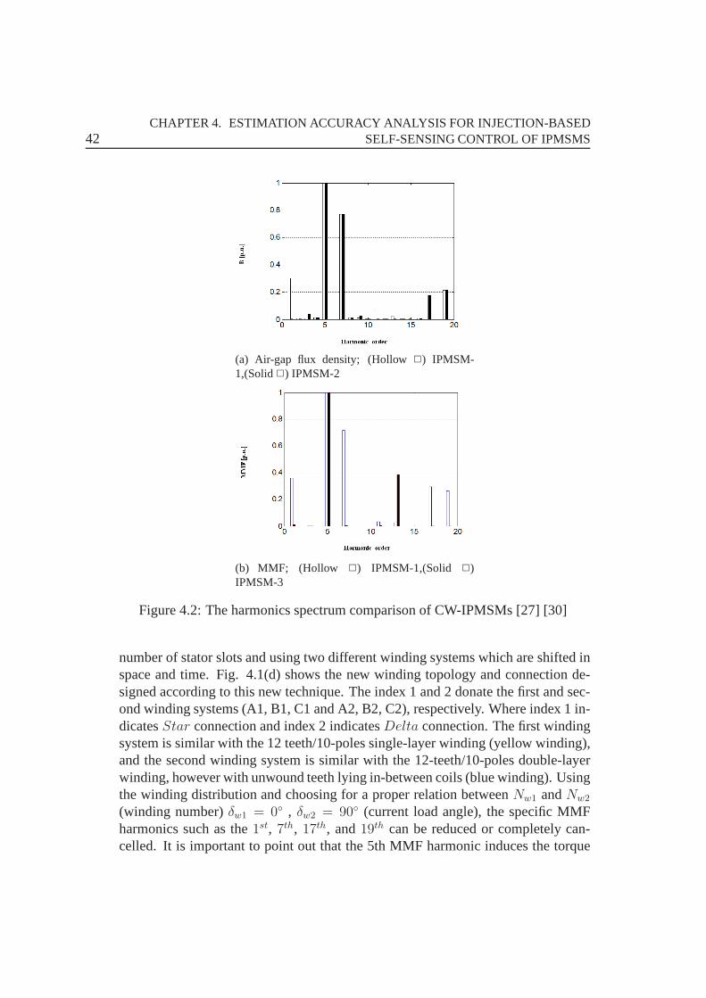
42CHAPTER 4. ESTIMATION ACCURACY ANALYSIS FOR INJECTION-BASED
SELF-SENSING CONTROL OF IPMSMS
(a) Air-gap flux density; (Hollow) IPMSM-1,(Solid) IPMSM-2
(b) MMF; (Hollow ) IPMSM-1,(Solid )IPMSM-3
Figure 4.2: The harmonics spectrum comparison of CW-IPMSMs[27] [30]
number of stator slots and using two different winding systems which are shifted inspace and time. Fig. 4.1(d) shows the new winding topology and connection de-signed according to this new technique. The index 1 and 2 donate the first and sec-ond winding systems (A1, B1, C1 and A2, B2, C2), respectively. Where index 1 in-dicatesStar connection and index 2 indicatesDelta connection. The first windingsystem is similar with the 12 teeth/10-poles single-layer winding (yellow winding),and the second winding system is similar with the 12-teeth/10-poles double-layerwinding, however with unwound teeth lying in-between coils(blue winding). Usingthe winding distribution and choosing for a proper relationbetweenNw1 andNw2
(winding number)δw1 = 0 , δw2 = 90 (current load angle), the specific MMFharmonics such as the1st, 7th, 17th, and19th can be reduced or completely can-celled. It is important to point out that the 5th MMF harmonicinduces the torque
4.2. MACHINE MODELING AND HF INJECTION METHOD 43
as the fundamental. Fig. 4.2 compares MMF harmonics spectrum results for theconventional 12 teeth/10-poles and the new 18 teeth/10-poles winding. It can beseen that most of the sub- and high- MMF harmonics of IPMSM-3 are cancelled.IPMSM-3 with the new winding type the radial force modes of low order (mode-2)the sub-harmonics of which are reduced about 70%, the statorand rotor iron lossesare reduced 30% and the magnet losses are reduced 80%.
The advantage of novel designed machines with reduced sub-harmonics bringingeddy current reduction is not only a great benefit to the machine loss, but also at-tractive to the self-sensing control with HF injection. This chapter focuses on theHF injection-based self-sensing method of these two new designed CW-IPMSMs,in order to evaluate the control performance of self-sensing technology.
4.2 Machine Modeling and HF Injection Method
A summary of the used symbols is given in appendix. The statorflux linkage vectorequation of IPMSMs can be expressed as
Ψs = Lsis +Ψpm (4.1)
where
Ls =
[ΣL+∆L cos 2θ ∆L sin 2θ
∆L sin 2θ ΣL−∆L cos 2θ
](4.2)
ΣL = 1/2(Ld + Lq) ∆L = 1/2(Lq − Ld) (4.3)
The stator voltage vector equation can be expressed as
us = Rsis +dΨs
dt(4.4)
When a HF voltage or current vector signal is injected, the stator voltage equationnormally ignores the resistance and the electromotive force (EMF), because theseare much lower than the inductance voltage for high frequencies and can thereforebe simplified to
us = Lsdisdt
(4.5)
If a three-phase HF sine voltage signal is injected into the IPMSMs, a rotatingspace voltage vector with constant amplitude and high speedin the machines willbe achieved. The injection voltage can be described as
usc = |uc|(cosωct+ jsinωct) = |uc|e
jωct (4.6)
44CHAPTER 4. ESTIMATION ACCURACY ANALYSIS FOR INJECTION-BASED
SELF-SENSING CONTROL OF IPMSMS
whereωc is the injection AC voltage frequency,|uc| is the amplitude of rotatingvoltage vector.
The induced carrier current vectorisc can be calculated as
isc = −j|ip|ejωct +−j|in|e
j(−ωct+2θ) (4.7)
where
|ip| =ΣL
ΣL2 −∆L2
|uc|
ωc
(4.8)
|in| =∆L
ΣL2 −∆L2
|uc|
ωc(4.9)
Equation (4.7) describes the superimposed stator current vector composed twocomponents: one vectorip is rotating in positive direction according to the injectionangular speedωc ; the other vectorin is rotating in negative direction according to
the angular speed−ωc + 2ωr (ωr =dθ
dt), and the rotational speed informationωr
only is included in the vectorin.This chapter focuses on the rotating HF voltage injection method, but in the case
of pulsating signal injection with different signal processing the performance wouldbe different. Especially, pulsating signal injection would be robust to local saliencyand cross saturation. In order to prove the novel machine design is attractive to theself-sensing control, the less robust injection method is used.
4.3 Analysis of Estimation Accuracy
There are many sources which affect the estimation accuracyin the self-sensingsystem of IPMSMs based on HF injection, these are saturation, eddy current, HFrotor/stator resistance, temperature, carrier voltage distortion, inverter-nonlinearityand so on. One of the major issues is saturation effects [16] [42] [105] which in-clude: 1) signal-to-noise-ratio (SNR) changing with the saliency ratio of the ma-chine; 2) cross saturation depending on the stator rotor design when the machine isunder load; 3) harmonic distortion caused by secondary saliencies and saturation-induced saliencies.
These saliencies depend on the flux waveform in the air gap that is a function ofthe stator and rotor design, and they can be reduced by a proper machine design.Due to the new designed IPMSMs have the advantage of lower sub- & high- MMFharmonics and lower eddy current loss. These characteristics are investigated toprove the new machines being more qualified to be controlled without an encoder.
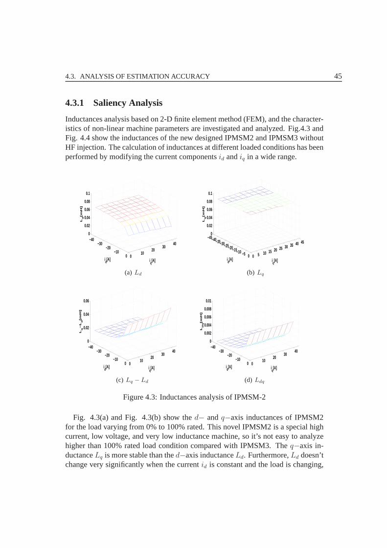
4.3. ANALYSIS OF ESTIMATION ACCURACY 45
4.3.1 Saliency Analysis
Inductances analysis based on 2-D finite element method (FEM), and the character-istics of non-linear machine parameters are investigated and analyzed. Fig.4.3 andFig. 4.4 show the inductances of the new designed IPMSM2 and IPMSM3 withoutHF injection. The calculation of inductances at different loaded conditions has beenperformed by modifying the current componentsid andiq in a wide range.
010
2030
40
0−10
−20−30
−400
0.02
0.04
0.06
0.08
0.1
iq[A]i
d[A]
Ld[m
H]
(a) Ld
0 5 10 15 20 25 30 35 40 45
0−5−10−15−20−25−30−35−40−450
0.02
0.04
0.06
0.08
0.1
iq[A]i
d[A]
Lq[m
H]
(b) Lq
010
2030
40
0−10
−20−30
−400
0.02
0.04
0.06
iq[A]i
d[A]
Lq−
Ld[m
H]
(c) Lq − Ld
010
2030
40
0−10
−20−30
−400
0.002
0.004
0.006
0.008
0.01
iq[A]i
d[A]
Ldq[m
H]
(d) Ldq
Figure 4.3: Inductances analysis of IPMSM-2
Fig. 4.3(a) and Fig. 4.3(b) show thed− andq−axis inductances of IPMSM2for the load varying from 0% to 100% rated. This novel IPMSM2 is a special highcurrent, low voltage, and very low inductance machine, so it’s not easy to analyzehigher than 100% rated load condition compared with IPMSM3.The q−axis in-ductanceLq is more stable than thed−axis inductanceLd. Furthermore,Ld doesn’tchange very significantly when the currentid is constant and the load is changing,
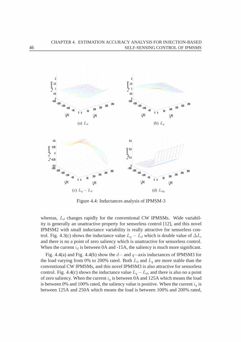
46CHAPTER 4. ESTIMATION ACCURACY ANALYSIS FOR INJECTION-BASED
SELF-SENSING CONTROL OF IPMSMS
0 50 100 150 200 250
0−50
−100−150
−200−250
0
0.5
1
1.5
2
iq[A]i
d[A]
Ld[m
H]
(a) Ld
0 50 100 150 200 250
0−50
−100−150
−200−250
0
0.5
1
1.5
2
iq[A]i
d[A]
Lq[m
H]
(b) Lq
0 50 100 150 200 250
0−50
−100−150
−200−250−0.5
−0.25
0
0.25
0.5
iq[A]i
d[A]
Lq−
Ld[m
H]
(c) Lq − Ld
0 50 100 150 200 250
0−50
−100−150
−200−250
0
0.1
0.2
0.3
iq[A]i
d[A]
Ldq[m
H]
(d) Ldq
Figure 4.4: Inductances analysis of IPMSM-3
whereas,Ld changes rapidly for the conventional CW IPMSMs. Wide variabil-ity is generally an unattractive property for sensorless control [12], and this novelIPMSM2 with small inductance variability is really attractive for sensorless con-trol. Fig. 4.3(c) shows the inductance valueLq − Ld which is double value of∆L,and there is no a point of zero saliency which is unattractivefor sensorless control.When the currentid is between 0A and -15A, the saliency is much more significant.
Fig. 4.4(a) and Fig. 4.4(b) show thed− andq−axis inductances of IPMSM3 forthe load varying from 0% to 200% rated. BothLd andLq are more stable than theconventional CW IPMSMs, and this novel IPMSM3 is also attractive for sensorlesscontrol. Fig. 4.4(c) shows the inductance valueLq −Ld, and there is also no a pointof zero saliency. When the currentiq is between 0A and 125A which means the loadis between 0% and 100% rated, the saliency value is positive.When the currentiq isbetween 125A and 250A which means the load is between 100% and200% rated,
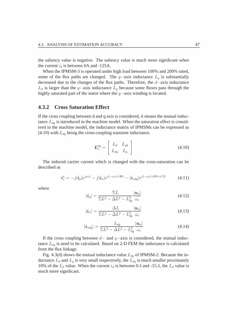
4.3. ANALYSIS OF ESTIMATION ACCURACY 47
the saliency value is negative. The saliency value is much more significant whenthe currentid is between 0A and -125A.
When the IPMSM-3 is operated under high load between 100% and200% rated,some of the flux paths are changed. Theq−axis inductanceLq is substantiallydecreased due to the changes of the flux paths. Therefore, thed−axis inductanceLd is larger than theq−axis inductanceLq because some fluxes pass through thehighly saturated part of the stator where theq−axis winding is located.
4.3.2 Cross Saturation Effect
If the cross coupling between d and q axis is considered, it means the mutual induc-tanceLdq is introduced in the machine model. When the saturation effect is consid-ered in the machine model, the inductance matrix of IPMSMs can be expressed as(4.10) withLdq being the cross-coupling transient inductance.
Ldqs =
[Ld Lqd
Ldq Lq
](4.10)
The induced carrier current which is changed with the cross-saturation can bedescribed as
isc = −j|ip|ejωct − j|in|e
j(−ωct+2θ) − |indq|ej(−ωct+2θ+π/2) (4.11)
where
|ip| =ΣL
ΣL2 −∆L2 − L2dq
|uc|
ωc(4.12)
|in| =∆L
ΣL2 −∆L2 − L2dq
|uc|
ωc
(4.13)
|indq| =Ldq
ΣL2 −∆L2 − L2dq
|uc|
ωc(4.14)
If the cross coupling betweend− andq−axis is considered, the mutual induc-tanceLdq is need to be calculated. Based on 2-D FEM the inductance is calculatedfrom the flux linkage.
Fig. 4.3(d) shows the mutual inductance valueLdq of IPMSM-2. Because the in-ductanceLd andLq is very small respectively, theLdq is much smaller proximately10% of theLd value. When the currentid is between 0A and -15A, theLd value ismuch more significant.
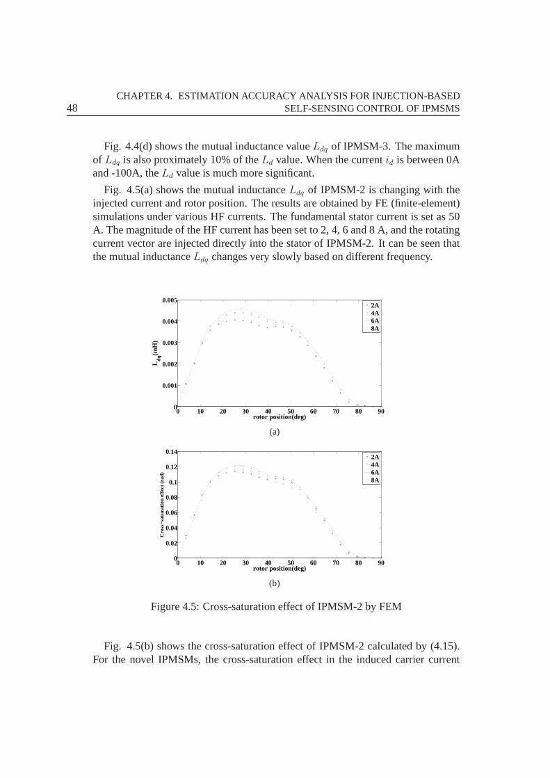
48CHAPTER 4. ESTIMATION ACCURACY ANALYSIS FOR INJECTION-BASED
SELF-SENSING CONTROL OF IPMSMS
Fig. 4.4(d) shows the mutual inductance valueLdq of IPMSM-3. The maximumof Ldq is also proximately 10% of theLd value. When the currentid is between 0Aand -100A, theLd value is much more significant.
Fig. 4.5(a) shows the mutual inductanceLdq of IPMSM-2 is changing with theinjected current and rotor position. The results are obtained by FE (finite-element)simulations under various HF currents. The fundamental stator current is set as 50A. The magnitude of the HF current has been set to 2, 4, 6 and 8 A,and the rotatingcurrent vector are injected directly into the stator of IPMSM-2. It can be seen thatthe mutual inductanceLdq changes very slowly based on different frequency.
0 10 20 30 40 50 60 70 80 900
0.001
0.002
0.003
0.004
0.005
rotor position(deg)
Ldq
(mH
)
2A4A6A8A
(a)
0 10 20 30 40 50 60 70 80 900
0.02
0.04
0.06
0.08
0.1
0.12
0.14
rotor position(deg)
Cro
ss−
satu
ratio
n ef
fect
(ra
d)
2A4A6A8A
(b)
Figure 4.5: Cross-saturation effect of IPMSM-2 by FEM
Fig. 4.5(b) shows the cross-saturation effect of IPMSM-2 calculated by (4.15).For the novel IPMSMs, the cross-saturation effect in the induced carrier current

4.3. ANALYSIS OF ESTIMATION ACCURACY 49
(4.11) is very small and the resulting position estimated error is also not significant.
Φ = sin−1(Ldq
ΣL2 −∆L2 − L2dq
) (4.15)
4.3.3 High Frequency Inductance Effect
If using the HF injection method for self-sensing control ofIPMSMs, it is necessaryto analyze the frequency response of inductances. Fig. 4.6 shows the results mea-sured by theBode100 which is a vector network analyzer. This impedance analyzercan get the transient impedances in a frequency range from 1 Hz to 40 MHz, whenmachines are operated at stand still.
Fig. 4.6(a) shows that the phase inductance between the phase endpoint and theneutral point for IPMSM-2 changes significantly when the frequency is between 10Hz and 100 Hz. The inductances decrease slowly when the frequency is between100 Hz and 1000 Hz, and this period with small variability is generally an attractiveproperty for self-sensing control.
The line inductance between the phase endpoint and another for IPMSM-3 changesvery slowly between 100 Hz and 1000 Hz in Fig. 4.6(b). The resonance effects at 35Hz and 100 Hz can be explained as follows. At lower frequencies the serial stand-still inductance of IPMSM-3 is around 1 mH. The figure shows that the inductancestarts decreasing at a frequency around 35 Hz and shows a resonance at 100 Hz. Fora frequency higher than the resonance frequency, the coil has a capacitive behaviorexcept within a small frequency range where it regains inductive characteristic. Thisindicates a parallel resonance as the inductance is active for low frequency whilstthe capacitive part is active for high frequency.
The analysis of inductances with different frequency can help in the choice ofHF signal which is important for self-sensing. Finally, thecarrier frequency of theinjected HF voltage needs to be chosen carefully. On the one hand, the frequencyof the voltage injected needs to be chosen far from the fundamental machine oper-ating frequency to achieve signal separation with high bandwidth and nearly zerophase distortion. On the other hand, the carrier frequency cannot be set too closeto the switching frequency because the sinusoidal waveforminjected will be dis-torted if there are not enough sample points in one sinusoidal cycle of the carrierhigh frequency voltage. Furthermore, considering the inductance, the choice of HFsignal should avoid the wide variability period. In this chapter, 800 Hz is selectedto ensure nearly a sinusoidal waveform with smaller harmonics.
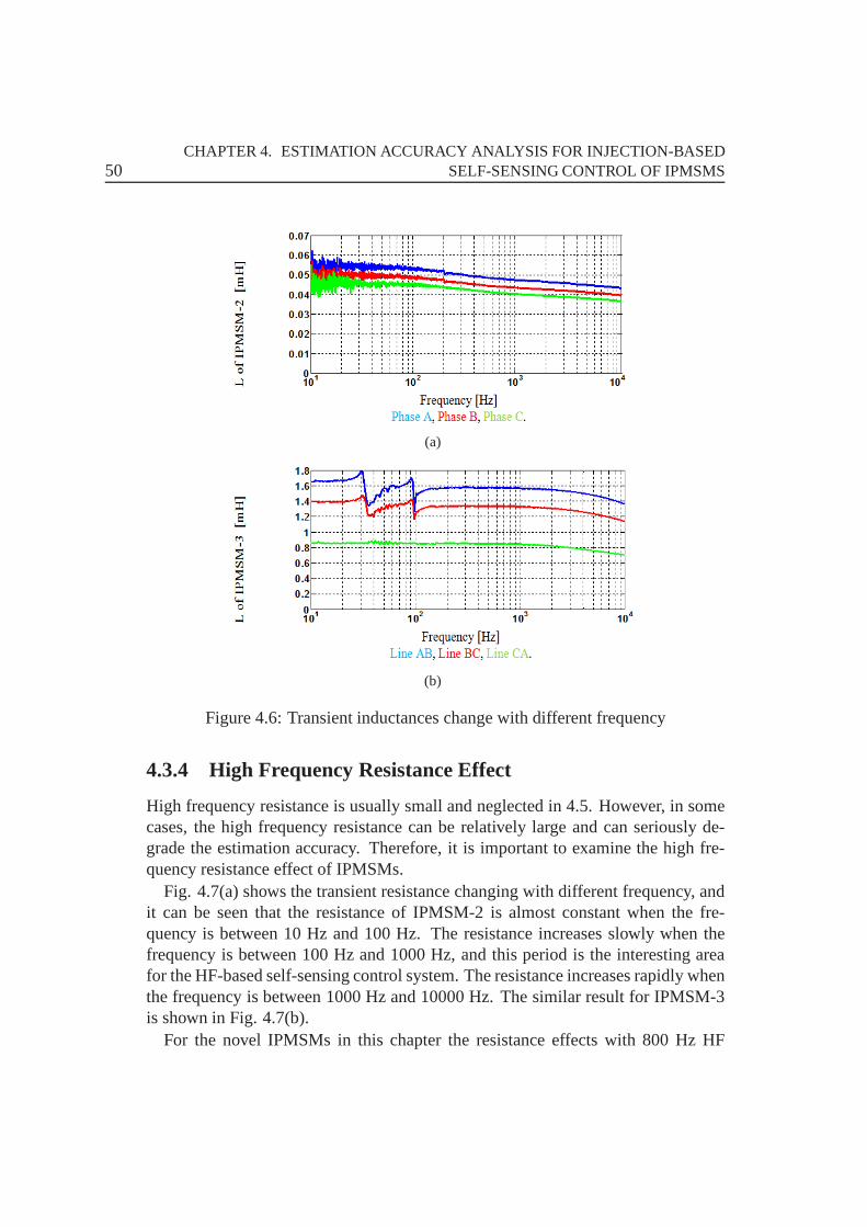
50CHAPTER 4. ESTIMATION ACCURACY ANALYSIS FOR INJECTION-BASED
SELF-SENSING CONTROL OF IPMSMS
(a)
(b)
Figure 4.6: Transient inductances change with different frequency
4.3.4 High Frequency Resistance Effect
High frequency resistance is usually small and neglected in4.5. However, in somecases, the high frequency resistance can be relatively large and can seriously de-grade the estimation accuracy. Therefore, it is important to examine the high fre-quency resistance effect of IPMSMs.
Fig. 4.7(a) shows the transient resistance changing with different frequency, andit can be seen that the resistance of IPMSM-2 is almost constant when the fre-quency is between 10 Hz and 100 Hz. The resistance increases slowly when thefrequency is between 100 Hz and 1000 Hz, and this period is theinteresting areafor the HF-based self-sensing control system. The resistance increases rapidly whenthe frequency is between 1000 Hz and 10000 Hz. The similar result for IPMSM-3is shown in Fig. 4.7(b).
For the novel IPMSMs in this chapter the resistance effects with 800 Hz HF
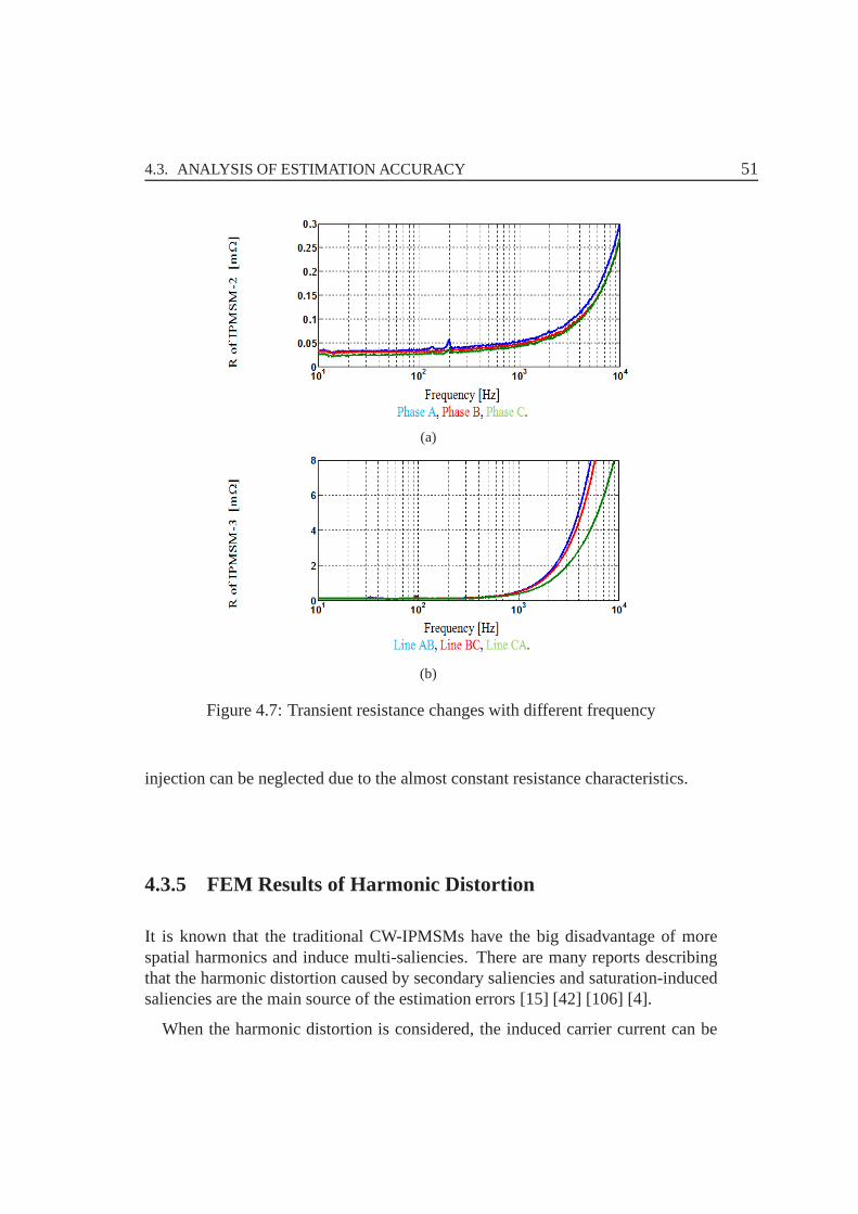
4.3. ANALYSIS OF ESTIMATION ACCURACY 51
(a)
(b)
Figure 4.7: Transient resistance changes with different frequency
injection can be neglected due to the almost constant resistance characteristics.
4.3.5 FEM Results of Harmonic Distortion
It is known that the traditional CW-IPMSMs have the big disadvantage of morespatial harmonics and induce multi-saliencies. There are many reports describingthat the harmonic distortion caused by secondary saliencies and saturation-inducedsaliencies are the main source of the estimation errors [15][42] [106] [4].
When the harmonic distortion is considered, the induced carrier current can be
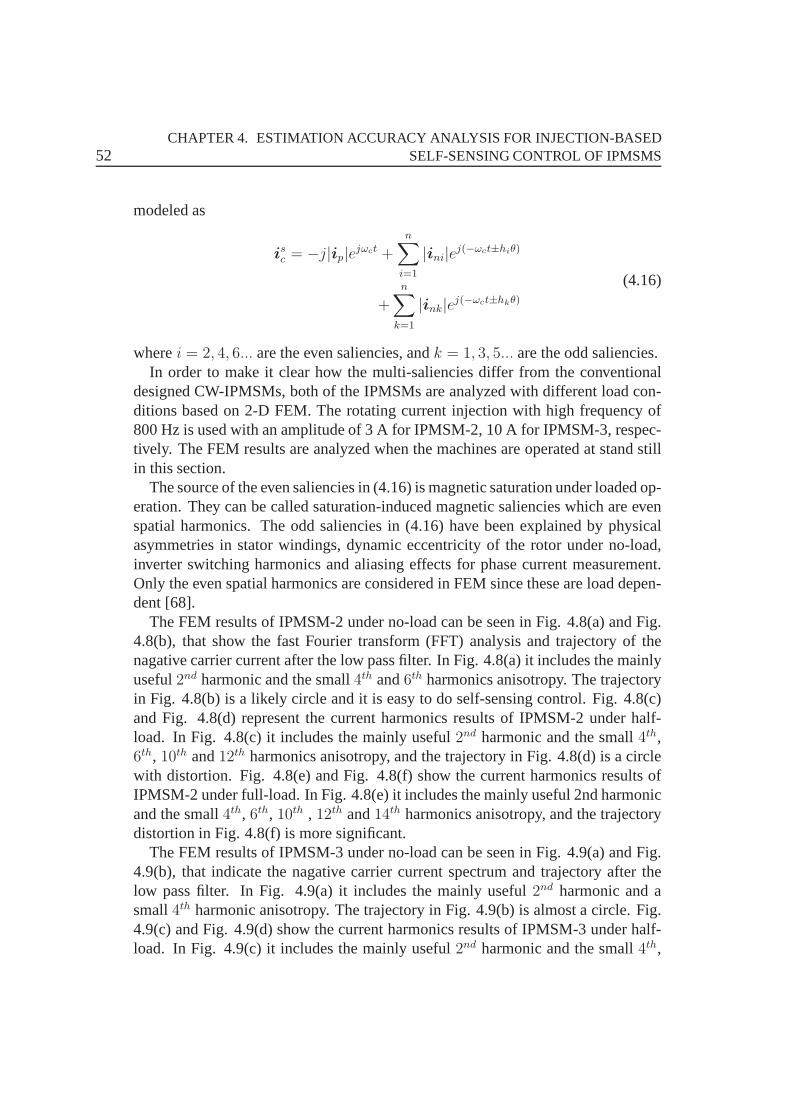
52CHAPTER 4. ESTIMATION ACCURACY ANALYSIS FOR INJECTION-BASED
SELF-SENSING CONTROL OF IPMSMS
modeled as
isc = −j|ip|ejωct +
n∑
i=1
|ini|ej(−ωct±hiθ)
+n∑
k=1
|ink|ej(−ωct±hkθ)
(4.16)
wherei = 2, 4, 6... are the even saliencies, andk = 1, 3, 5... are the odd saliencies.In order to make it clear how the multi-saliencies differ from the conventional
designed CW-IPMSMs, both of the IPMSMs are analyzed with different load con-ditions based on 2-D FEM. The rotating current injection with high frequency of800 Hz is used with an amplitude of 3 A for IPMSM-2, 10 A for IPMSM-3, respec-tively. The FEM results are analyzed when the machines are operated at stand stillin this section.
The source of the even saliencies in (4.16) is magnetic saturation under loaded op-eration. They can be called saturation-induced magnetic saliencies which are evenspatial harmonics. The odd saliencies in (4.16) have been explained by physicalasymmetries in stator windings, dynamic eccentricity of the rotor under no-load,inverter switching harmonics and aliasing effects for phase current measurement.Only the even spatial harmonics are considered in FEM since these are load depen-dent [68].
The FEM results of IPMSM-2 under no-load can be seen in Fig. 4.8(a) and Fig.4.8(b), that show the fast Fourier transform (FFT) analysisand trajectory of thenagative carrier current after the low pass filter. In Fig. 4.8(a) it includes the mainlyuseful2nd harmonic and the small4th and6th harmonics anisotropy. The trajectoryin Fig. 4.8(b) is a likely circle and it is easy to do self-sensing control. Fig. 4.8(c)and Fig. 4.8(d) represent the current harmonics results of IPMSM-2 under half-load. In Fig. 4.8(c) it includes the mainly useful2nd harmonic and the small4th,6th, 10th and12th harmonics anisotropy, and the trajectory in Fig. 4.8(d) is acirclewith distortion. Fig. 4.8(e) and Fig. 4.8(f) show the current harmonics results ofIPMSM-2 under full-load. In Fig. 4.8(e) it includes the mainly useful 2nd harmonicand the small4th, 6th, 10th , 12th and14th harmonics anisotropy, and the trajectorydistortion in Fig. 4.8(f) is more significant.
The FEM results of IPMSM-3 under no-load can be seen in Fig. 4.9(a) and Fig.4.9(b), that indicate the nagative carrier current spectrum and trajectory after thelow pass filter. In Fig. 4.9(a) it includes the mainly useful2nd harmonic and asmall4th harmonic anisotropy. The trajectory in Fig. 4.9(b) is almost a circle. Fig.4.9(c) and Fig. 4.9(d) show the current harmonics results ofIPMSM-3 under half-load. In Fig. 4.9(c) it includes the mainly useful2nd harmonic and the small4th,
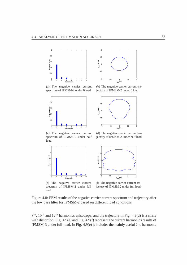
4.3. ANALYSIS OF ESTIMATION ACCURACY 53
0 2 4 6 8 10 12 140
0.2
0.4
0.6
0.8
1
Harmonic order
Cu
rre
nt
[p.u
.]
(a) The nagative carrier currentspectrum of IPMSM-2 under 0 load
−1 −0.5 0 0.5 1−1
−0.5
0
0.5
1
ialpha
[p.u.]
i be
ta [
p.u
.]
(b) The nagative carrier current tra-jectory of IPMSM-2 under 0 load
0 2 4 6 8 10 12 140
0.2
0.4
0.6
0.8
1
Harmonic order
Cu
rre
nt [p
.u.]
(c) The nagative carrier currentspectrum of IPMSM-2 under halfload
−1 −0.5 0 0.5 1−1
−0.5
0
0.5
1
ialpha
[p.u.]
i be
ta [p
.u.]
(d) The nagative carrier current tra-jectory of IPMSM-2 under half load
0 2 4 6 8 10 12 140
0.2
0.4
0.6
0.8
1
Harmonic order
Cu
rre
nt
[p.u
.]
(e) The nagative carrier currentspectrum of IPMSM-2 under fullload
−1 −0.5 0 0.5 1−1
−0.5
0
0.5
1
ialpha
[p.u.]
i be
ta [p
.u.]
(f) The nagative carrier current tra-jectory of IPMSM-2 under full load
Figure 4.8: FEM results of the negative carrier current spectrum and trajectory afterthe low pass filter for IPMSM-2 based on different load conditions
8th, 10th and12th harmonics anisotropy, and the trajectory in Fig. 4.9(d) is acirclewith distortion. Fig. 4.9(e) and Fig. 4.9(f) represent the current harmonics results ofIPMSM-3 under full-load. In Fig. 4.9(e) it includes the mainly useful 2nd harmonic
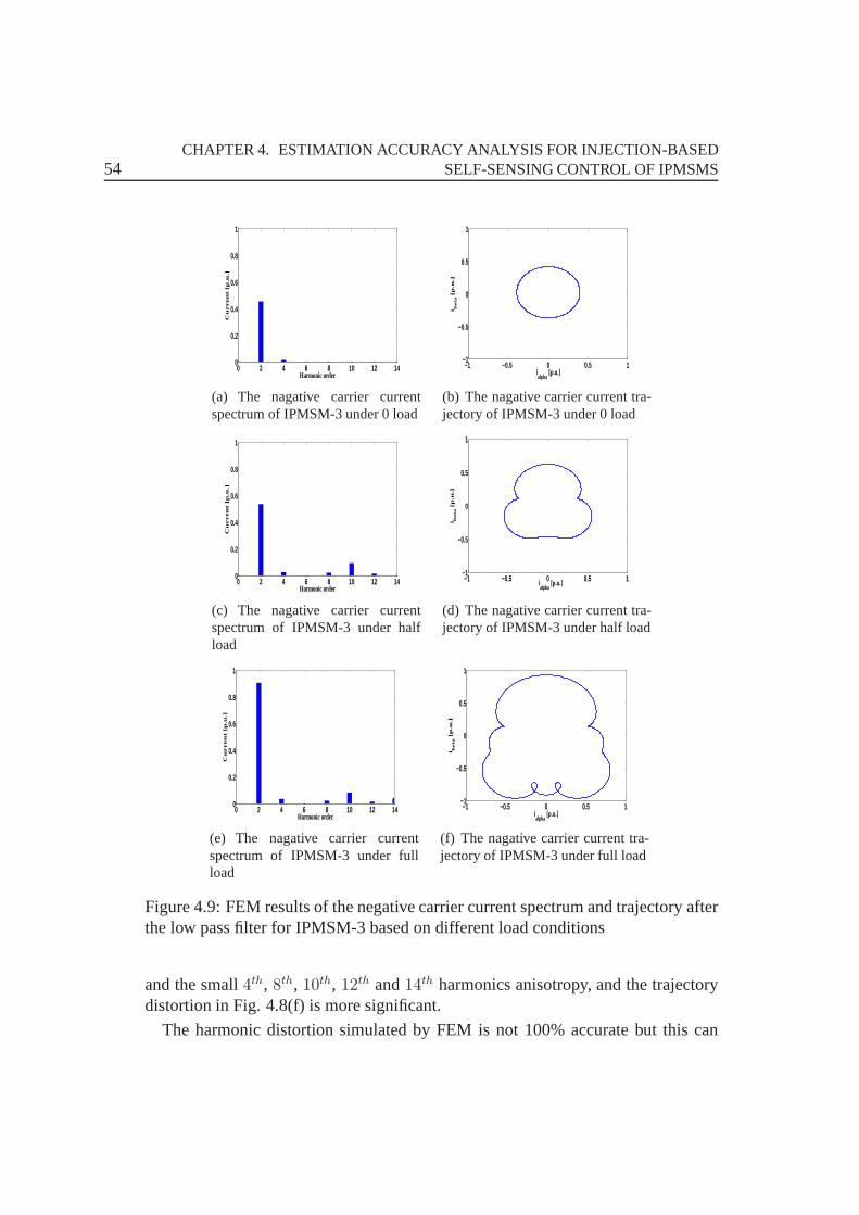
54CHAPTER 4. ESTIMATION ACCURACY ANALYSIS FOR INJECTION-BASED
SELF-SENSING CONTROL OF IPMSMS
0 2 4 6 8 10 12 140
0.2
0.4
0.6
0.8
1
Harmonic order
Cu
rre
nt
[p.u
.]
(a) The nagative carrier currentspectrum of IPMSM-3 under 0 load
−1 −0.5 0 0.5 1−1
−0.5
0
0.5
1
ialpha
[p.u.]
i be
ta [
p.u
.]
(b) The nagative carrier current tra-jectory of IPMSM-3 under 0 load
0 2 4 6 8 10 12 140
0.2
0.4
0.6
0.8
1
Harmonic order
Cu
rre
nt
[p.u
.]
(c) The nagative carrier currentspectrum of IPMSM-3 under halfload
−1 −0.5 0 0.5 1−1
−0.5
0
0.5
1
ialpha
[p.u.]
i be
ta [
p.u
.]
(d) The nagative carrier current tra-jectory of IPMSM-3 under half load
0 2 4 6 8 10 12 140
0.2
0.4
0.6
0.8
1
Harmonic order
Cu
rre
nt
[p.u
.]
(e) The nagative carrier currentspectrum of IPMSM-3 under fullload
−1 −0.5 0 0.5 1−1
−0.5
0
0.5
1
ialpha
[p.u.]
i be
ta [
p.u
.]
(f) The nagative carrier current tra-jectory of IPMSM-3 under full load
Figure 4.9: FEM results of the negative carrier current spectrum and trajectory afterthe low pass filter for IPMSM-3 based on different load conditions
and the small4th, 8th, 10th, 12th and14th harmonics anisotropy, and the trajectorydistortion in Fig. 4.8(f) is more significant.
The harmonic distortion simulated by FEM is not 100% accurate but this can

4.4. IMPLEMENTATION AND EXPERIMENTAL RESULTS 55
show the load dependency characteristics of the novel IPMSMs. It can be seen inFig. 4.8 and Fig. 4.9 that the different current harmonics affect the current circletrajectory, which affects the estimation accuracy of self-sensing control. For thenovel designed machines the distortion is not serious compared with the conven-tional machines which even can be a triangle trajectory.
4.4 Implementation and Experimental Results
4.4.1 Hardware Description
Both of the CW-IPMSMs test benches are based on the dSPACE real-time controlplatform, and there is no test bench for IPMSM-1 since it is only a simulation model.The control system utilizes the dSPACE development platform as the controller andgenerates the real-time code for the control algorithm and motor model. The controlparameters can be tuned on-line.
The IPMSM-2 is supplied by a modified MACCON 2 k VA inverter which pro-vides full control over the MOSFETs, and the actual rotor position is measured bya 4096 lines absolute encoder. The IPMSM-3 is supplied by a modified 50 k VA in-verter which provides full control over the IGBT gates, and the actual rotor positionis measured by a 4096 lines incremental encoder. In the experiments, the switchingfrequency of PWM for IPMSM-2 is 16 kHz, and for IPMSM-3 is 10 kHz. Fig. 4.10shows the test benches of IPMSMs, and the technical data of IPMSMs is given inTable 4.2.
4.4.2 Experimental Results of Harmonic Distortion
The harmonic distortion can be easily seen from the experimental results of current.The rotating voltage injection with high frequency of 800 Hzis used with an am-plitude of 3 V for IPMSM-2 and 10 V for IPMSM-3, respectively.Both machinesare tested and measured at the electrical rotor speed of4π rad/s (10 Hz) with theposition encoder.
Fig. 4.11(a) and Fig. 4.11(b) shows the fast fourier transform (FFT) analysisof the negative current vectorin under no-load, and the most noticeable secondarysaliencies around the negative-sequence component are induced at(−ωc − 2ωr)and(−ωc ± 4ωr). It can be seen the magnitude of the wanted(−ωc + 2ωr) (780HZ) component is definitely bigger than the even−2nd and−4nd harmonics. Forthe half-load condition in Fig. 4.11(c) and Fig. 4.11(d), the harmonic distortion iscaused by saliencies that are induced at(−ωc ± 4ωr), (−ωc ± 6ωr), (−ωc ± 8ωr),(−ωc ± 12ωr) , (−ωc ± 14ωr)and(−ωc − 2ωr) . Furthermore, the magnitude of
56CHAPTER 4. ESTIMATION ACCURACY ANALYSIS FOR INJECTION-BASED
SELF-SENSING CONTROL OF IPMSMS
(a) The test bench of IPMSM-2 (b) The front view of IPMSM-2
(c) The test bench of IPMSM-3 (d) The front view of IPMSM-3
Figure 4.10: The test benches of novel IPMSMs
the (−ωc + 2ωr) (780 HZ) component is bigger than that under no-load, and themagnitudes of the other harmonic orders are also increased.However, the increasedharmonics compared with the dominant spatial saliency (780Hz) are much smaller,whereas, these harmonics are very big in the conventional IPMSMs and have to usethe decoupled compensation method.
Fig. 4.12 shows the carrier current sequence rotates at twice the electrical rotorspeed with a likely circular trajectory without fundamental current when under no-load and half-load condition. The trajectory is normally not a circle for the conven-tional design IPMSMs especially under load. The novel designed IPMSMs havethe big advantage of lower spatial harmonics, which inducesthe lower harmonicdistortion of the current.
Since the harmonic distortion is not serious in the novel IPMSMs, it again provesthat these new design are really attractive for self-sensing control especially basedon a HF injection method and it makes accurately self-sensing control easily withoutdecoupling the harmonic distortion. However, if some industry communities needvery precisely self-sensing control performances, these novel IPMSMs also need todecouple the multi-saliencies harmonics.
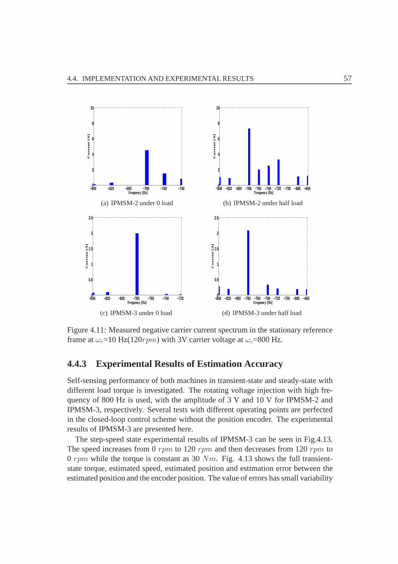
4.4. IMPLEMENTATION AND EXPERIMENTAL RESULTS 57
−840 −820 −800 −780 −760 −7400
2
4
6
8
10
Frequency [Hz]
Cu
rre
nt
[A]
(a) IPMSM-2 under 0 load
−840 −820 −800 −780 −760 −740 −720 −700 −680 −6600
2
4
6
8
10
Frequency [Hz]
Cu
rre
nt
[A]
(b) IPMSM-2 under half load
−840 −820 −800 −780 −760 −740 −7200
0.5
1
1.5
2
2.5
Frequency [Hz]
Cu
rre
nt
[A]
(c) IPMSM-3 under 0 load
−840 −820 −800 −780 −760 −740 −720 −700 −680 −6600
0.5
1
1.5
2
2.5
Cu
rre
nt
[A]
Frequency [Hz]
(d) IPMSM-3 under half load
Figure 4.11: Measured negative carrier current spectrum inthe stationary referenceframe atωr=10 Hz(120rpm) with 3V carrier voltage atωc=800 Hz.
4.4.3 Experimental Results of Estimation Accuracy
Self-sensing performance of both machines in transient-state and steady-state withdifferent load torque is investigated. The rotating voltage injection with high fre-quency of 800 Hz is used, with the amplitude of 3 V and 10 V for IPMSM-2 andIPMSM-3, respectively. Several tests with different operating points are perfectedin the closed-loop control scheme without the position encoder. The experimentalresults of IPMSM-3 are presented here.
The step-speed state experimental results of IPMSM-3 can beseen in Fig.4.13.The speed increases from 0rpm to 120rpm and then decreases from 120rpm to0 rpm while the torque is constant as 30Nm. Fig. 4.13 shows the full transient-state torque, estimated speed, estimated position and estimation error between theestimated position and the encoder position. The value of errors has small variability
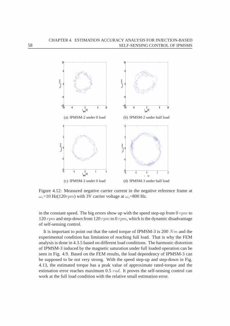
58CHAPTER 4. ESTIMATION ACCURACY ANALYSIS FOR INJECTION-BASED
SELF-SENSING CONTROL OF IPMSMS
−10 −6 0 6 10−10
−6
0
6
10
ialpha
[A]
i be
ta[A
]
(a) IPMSM-2 under 0 load
−10 −6 0 6 10−10
−6
0
6
10
i be
ta[A
]
ialpha
[A]
(b) IPMSM-2 under half load
−2 −1 0 1 2−2
−1
0
1
2
ialpha
[A]
i be
ta[A
]
(c) IPMSM-3 under 0 load
−2 −1 0 1 2−2
−1
0
1
2
i be
ta[A
]
i [A]
(d) IPMSM-3 under half load
Figure 4.12: Measured negative carrier current in the negative reference frame atωr=10 Hz(120rpm) with 3V carrier voltage atωc=800 Hz.
in the constant speed. The big errors show up with the speed step-up from 0rpm to120rpm and step-down from 120rpm to 0rpm, which is the dynamic disadvantageof self-sensing control.
It is important to point out that the rated torque of IPMSM-3 is 200Nm and theexperimental condition has limitation of reaching full load. That is why the FEManalysis is done in 4.3.5 based on different load conditions. The harmonic distortionof IPMSM-3 induced by the magnetic saturation under full loaded operation can beseen in Fig. 4.9. Based on the FEM results, the load dependency of IPMSM-3 canbe supposed to be not very strong. With the speed step-up and step-down in Fig.4.13, the estimated torque has a peak value of approximate rated-torque and theestimation error reaches maximum 0.5rad. It proves the self-sensing control canwork at the full load condition with the relative small estimation error.
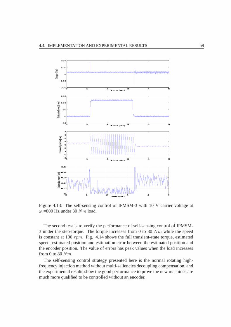
4.4. IMPLEMENTATION AND EXPERIMENTAL RESULTS 59
0 1 2 3 4 5−200
−100
0
100
200
Time [sec]
Torqu
e [Nm]
0 1 2 3 4 5−50
0
50
100
150
Time [sec]
Estim
ated s
peed [r
pm]
0 1 2 3 4 5−1
0
1
2
3
4
5
6
7
Time [sec]
Estim
ated p
osition
[rad]
0 1 2 3 4 50
0.1
0.2
0.3
0.4
0.5
Time [sec]
Estim
ation e
rror [r
ad]
Figure 4.13: The self-sensing control of IPMSM-3 with 10 V carrier voltage atωc=800 Hz under 30Nm load.
The second test is to verify the performance of self-sensingcontrol of IPMSM-3 under the step-torque. The torque increases from 0 to 80Nm while the speedis constant at 100rpm. Fig. 4.14 shows the full transient-state torque, estimatedspeed, estimated position and estimation error between theestimated position andthe encoder position. The value of errors has peak values when the load increasesfrom 0 to 80Nm.
The self-sensing control strategy presented here is the normal rotating high-frequency injection method without multi-saliencies decoupling compensation, andthe experimental results show the good performance to provethe new machines aremuch more qualified to be controlled without an encoder.
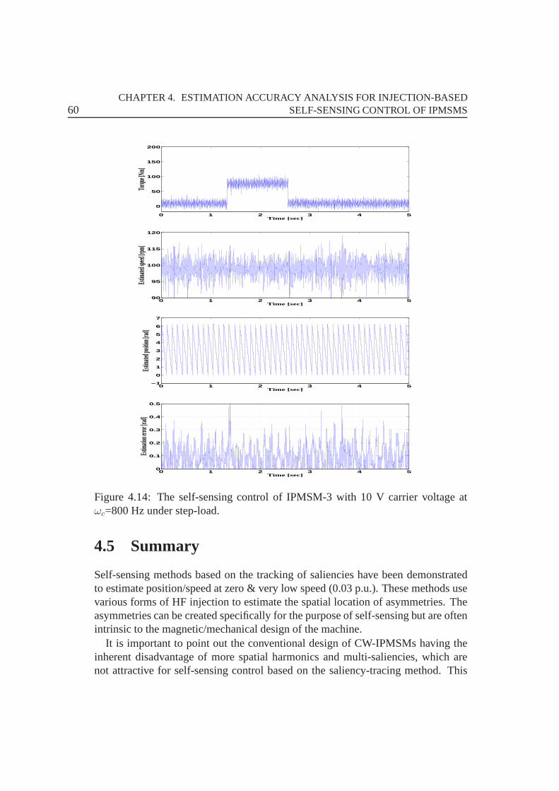
60CHAPTER 4. ESTIMATION ACCURACY ANALYSIS FOR INJECTION-BASED
SELF-SENSING CONTROL OF IPMSMS
0 1 2 3 4 5
0
50
100
150
200
Time [sec]
Torqu
e [Nm]
0 1 2 3 4 590
95
100
115
120
Time [sec]
Estim
ated s
peed [r
pm]
0 1 2 3 4 5−1
0
1
2
3
4
5
6
7
Time [sec]
Estim
ated p
osition
[rad]
0 1 2 3 4 50
0.1
0.2
0.3
0.4
0.5
Estim
ation e
rror [r
ad]
Time [sec]
Figure 4.14: The self-sensing control of IPMSM-3 with 10 V carrier voltage atωc=800 Hz under step-load.
4.5 Summary
Self-sensing methods based on the tracking of saliencies have been demonstratedto estimate position/speed at zero & very low speed (0.03 p.u.). These methods usevarious forms of HF injection to estimate the spatial location of asymmetries. Theasymmetries can be created specifically for the purpose of self-sensing but are oftenintrinsic to the magnetic/mechanical design of the machine.
It is important to point out the conventional design of CW-IPMSMs having theinherent disadvantage of more spatial harmonics and multi-saliencies, which arenot attractive for self-sensing control based on the saliency-tracing method. This

4.5. SUMMARY 61
chapter focuses on how the machine design affects the saliency-based self-sensingmethod.
There are two novel CW-IPMSM designs, and both of them have lower sub-harmonics content. The IPMSM-2 has fractional slot tooth concentrated windingsusing magnetic flux barriers in stator yoke. The IPMSM-3 has anew winding typeconsisting of two winding systems are shifted in space and time to each other for aspecific angle, the number of slots per pole and per phase for the winding systemsis different, and also the winding systems are characterized with a different numberof turns per coil. Using such a combination, the specific MMF harmonics for theconsidered concentrated winding can be reduced or completely canceled.
According to these new machine design techniques, the two novel CW-IPMSMsfor self-sensing application are tested and their characteristics are compared withthe conventional machines. Both of them are attractive for self-sensing especiallybased on the HF injection method at low constant speed & torque with smallerestimation errors. It could be proved that the novel machinedesign can improveself-sensing capability and the estimation accuracy of self-sensing.
Considering the novel design of the CW-IPMSMs, the evaluation of self-sensingcontrol is done to prove their design merit. The obtained results show that thenew stator design brings significant advantages over the conventional design. Theself-sensing control connected with the machine design is promising research forindustry and will be a popular topic in the future. In order toget more accurateestimated results, especially for the CW-IPMSMs, the improvement of the machinedesign can be used to do high performance of self-sensing control.

62CHAPTER 4. ESTIMATION ACCURACY ANALYSIS FOR INJECTION-BASED
SELF-SENSING CONTROL OF IPMSMS
63
CHAPTER 5
Losses Analysis in IPMSMs Resulting from HFInjection for Self-sensing Control
A novel designed CW-IPMSM with reduction of low space (low-order) harmon-ics named IPMSM-2 is introduced in Chapter 4. This chapter analyzes the eddycurrent loss distributions in IPMSM-2 using injection-based self-sensing positionestimation. The novel machine design can reduce the influence of the HF signalinduced iron and magnet losses for self-sensing control. Firstly, the magnetomo-tive force (MMF) of CW-IPMSMs with HF Injection between the single-layer anddouble-layer windings are compared. Secondly, the HF currents harmonics betweenthe IPMSM-2 and the conventional IPMSM are compared. Finally, the general an-alytical solution is proposed to solve the losses calculation problem in IPMSMs,which is available for investigating the iron and magnet losses resulting from theHF injection.
5.1 New Stator Topology of IPMSM-2
The realization of the new stator core with flux barriers in the stator yoke can be per-formed by modifying the stator yoke structure in different ways such as using holesof different shapes, using stator slots with different slotdepth or dividing completelythe stator yoke in specific locations. Of course, as is mentioned previously, the newstator topology is related with different additional advantages receptively [27].
The new stator structure of IPMSM-2 is using different slot depth, and the coil-sides in the corresponding slots can be shift away from the slot-opening region toreduce proximity effect in the winding conductors which is presently mostly near
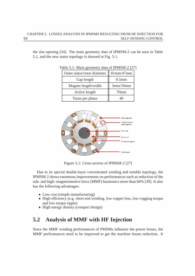
64CHAPTER 5. LOSSES ANALYSIS IN IPMSMS RESULTING FROM HF INJECTION FOR
SELF-SENSING CONTROL
the slot opening [24]. The main geometry data of IPMSM-2 can be seen in Table5.1, and the new stator topology is showed in Fig. 5.1.
Table 5.1: Main geometry data of IPMSM-2 [27]
Outer stator/rotor diameter 81mm/47mm
Gap length 0.5mm
Magnet length/width 3mm/10mm
Active length 70mm
Turns per phase 40
Figure 5.1: Cross section of IPMSM-2 [27]
Due to its special double-layer concentrated winding and notable topology, theIPMSM-2 shows enormous improvements on performances such as reduction of thesub- and high- magnetomotive force (MMF) harmonics more than 60% [30]. It alsohas the following advantages:
• Low cost (simple manufacturing)• High efficiency (e.g. short end winding, low copper loss, lowcogging torque
and low torque ripple)• High energy density (compact design)
5.2 Analysis of MMF with HF Injection
Since the MMF winding performances of PMSMs influence the power losses, theMMF performances need to be improved to get the machine losses reduction. It
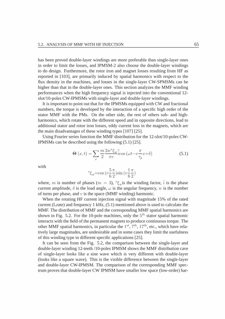
5.2. ANALYSIS OF MMF WITH HF INJECTION 65
has been proved double-layer windings are more preferable than single-layer onesin order to limit the losses, and IPMSM-2 also choose the double-layer windingsto do design. Furthermore, the rotor iron and magnet losses resulting from HF asreported in [103], are primarily induced by spatial harmonics with respect to theflux density in the machines, and losses in the single-layer CW-SPMSMs can behigher than that in the double-layer ones. This section analyzes the MMF windingperformances when the high frequency signal is injected into the conventional 12-slot/10-poles CW-IPMSMs with single-layer and double-layer windings.
It is important to point out that for the IPMSMs equipped withCW and fractionalnumbers, the torque is developed by the interaction of a specific high order of thestator MMF with the PMs. On the other side, the rest of others sub- and high-harmonics, which rotate with the different speed and in opposite directions, lead toadditional stator and rotor iron losses, eddy current loss in the magnets, which arethe main disadvantages of these winding types [107] [25].
Using Fourier series function the MMF distribution for the 12-slot/10-poles CW-IPMSMs can be described using the following (5.1) [25].
Θ (x, t) =∑
v
m
2
2wvξwπv
icos (ωt−v πτpx+δ) (5.1)
withvξw=cos (v
5
6
π
2)sin (v
1
6
π
2)
where,m is number of phases (m = 3), vξwis the winding factor,i is the phasecurrent amplitude,δ is the load angle,ω is the angular frequency,w is the numberof turns per phase, andv is the space (MMF winding) harmonic.
When the rotating HF current injection signal with magnitude 15% of the ratedcurrent (I rate) and frequency 1 kHz, (5.1) mentioned above is used to calculate theMMF. The distribution of MMF and the corresponding MMF spatial harmonics areshown in Fig. 5.2. For the 10-pole machines, only the5th stator spatial harmonicinteracts with the field of the permanent magnets to produce continuous torque. Theother MMF spatial harmonics, in particular the1st, 7th, 17th, etc., which have rela-tively large magnitudes, are undesirable and in some cases they limit the usefulnessof this winding type in different specific applications [25].
It can be seen from the Fig. 5.2, the comparison between the single-layer anddouble-layer winding 12-teeth /10-poles IPMSM shows the MMF distribution caveof single-layer looks like a sine wave which is very different with double-layer(looks like a square wave). This is the visible difference between the single-layerand double-layer CW-IPMSM. The comparison of the corresponding MMF spec-trum proves that double-layer CW IPMSM have smaller low space (low-order) har-
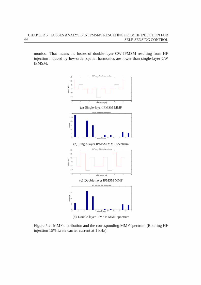
66CHAPTER 5. LOSSES ANALYSIS IN IPMSMS RESULTING FROM HF INJECTION FOR
SELF-SENSING CONTROL
monics. That means the losses of double-layer CW IPMSM resulting from HFinjection induced by low-order spatial harmonics are lowerthan single-layer CWIPMSM.
0 1 2 3 4 5 6 7−15
−10
−5
0
5
10
15
Rotor position [rad]
Sta
tor
MM
F
MMF curve of single layer winding
(a) Single-layer IPMSM MMF
0 2 4 6 8 10 12 14 16 18 200
5
10
15
20
25
30
Harmonic order
Mag
nitu
de
FFT of single layer winding MMF
(b) Single-layer IPMSM MMF spectrum
0 1 2 3 4 5 6 7−30
−20
−10
0
10
20
30
Rotor position [rad]
Sta
tor
MM
F
MMF curve of double layer winding
(c) Double-layer IPMSM MMF
0 2 4 6 8 10 12 14 16 18 200
5
10
15
20
Harmonic order
Ma
gn
itud
e
FFT of double layer winding MMF
(d) Double-layer IPMSM MMF spectrum
Figure 5.2: MMF distribution and the corresponding MMF spectrum (Rotating HFinjection 15% Irate carrier current at 1 kHz)
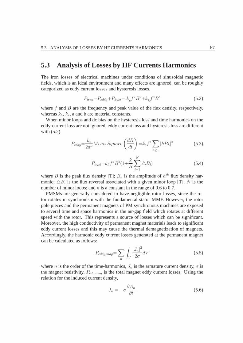
5.3. ANALYSIS OF LOSSES BY HF CURRENTS HARMONICS 67
5.3 Analysis of Losses by HF Currents Harmonics
The iron losses of electrical machines under conditions of sinusoidal magneticfields, which is an ideal environment and many effects are ignored, can be roughlycategorized as eddy current losses and hysteresis losses.
Piron=Peddy+Physt= kef2B2+k
hfaBb (5.2)
wheref andB are the frequency and peak value of the flux density, respectively,whereaskh, ke, a and b are material constants.
When minor loops and dc bias on the hysteresis loss and time harmonics on theeddy-current loss are not ignored, eddy current loss and hysteresis loss are differentwith (5.2).
Peddy=ke2π2
Mean Square
(dB
dt
)=kef
2∑
h≥1
|hBh|2 (5.3)
Physt=khfaBb(1+
k
B
N∑
i=1
Bi) (5.4)
whereB is the peak flux density [T];Bh is the amplitude ofhth flux density har-monic;Bi is the flux reversal associated with a given minor loop [T];N is thenumber of minor loops; andk is a constant in the range of 0.6 to 0.7.
PMSMs are generally considered to have negligible rotor losses, since the ro-tor rotates in synchronism with the fundamental stator MMF.However, the rotorpole pieces and the permanent magnets of PM synchronous machines are exposedto several time and space harmonics in the air-gap field whichrotates at differentspeed with the rotor. This represents a source of losses which can be significant.Moreover, the high conductivity of permanent magnet materials leads to significanteddy current losses and this may cause the thermal demagnetization of magnets.Accordingly, the harmonic eddy current losses generated atthe permanent magnetcan be calculated as follows:
Peddy,mag=∑
n
∫
V
|Jn|2
2σdV (5.5)
wheren is the order of the time-harmonics,Jn is the armature current density,σ isthe magnet resistivity,Pedd,mag is the total magnet eddy current losses. Using therelation for the induced current density,
Jn = −σ∂An
∂t(5.6)
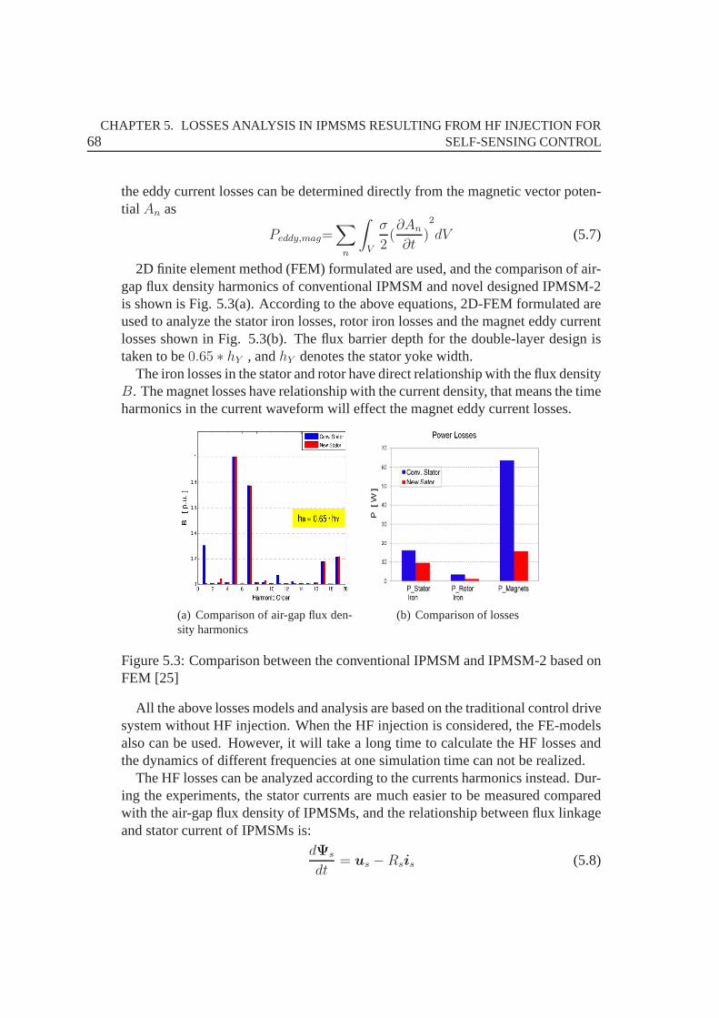
68CHAPTER 5. LOSSES ANALYSIS IN IPMSMS RESULTING FROM HF INJECTION FOR
SELF-SENSING CONTROL
the eddy current losses can be determined directly from the magnetic vector poten-tial An as
Peddy,mag=∑
n
∫
V
σ
2(∂An
∂t)2
dV (5.7)
2D finite element method (FEM) formulated are used, and the comparison of air-gap flux density harmonics of conventional IPMSM and novel designed IPMSM-2is shown is Fig. 5.3(a). According to the above equations, 2D-FEM formulated areused to analyze the stator iron losses, rotor iron losses andthe magnet eddy currentlosses shown in Fig. 5.3(b). The flux barrier depth for the double-layer design istaken to be0.65 ∗ hY , andhY denotes the stator yoke width.
The iron losses in the stator and rotor have direct relationship with the flux densityB. The magnet losses have relationship with the current density, that means the timeharmonics in the current waveform will effect the magnet eddy current losses.
(a) Comparison of air-gap flux den-sity harmonics
(b) Comparison of losses
Figure 5.3: Comparison between the conventional IPMSM and IPMSM-2 based onFEM [25]
All the above losses models and analysis are based on the traditional control drivesystem without HF injection. When the HF injection is considered, the FE-modelsalso can be used. However, it will take a long time to calculate the HF losses andthe dynamics of different frequencies at one simulation time can not be realized.
The HF losses can be analyzed according to the currents harmonics instead. Dur-ing the experiments, the stator currents are much easier to be measured comparedwith the air-gap flux density of IPMSMs, and the relationshipbetween flux linkageand stator current of IPMSMs is:
dΨs
dt= us − Rsis (5.8)
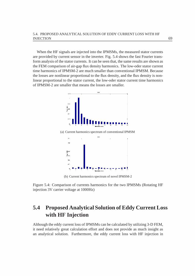
5.4. PROPOSED ANALYTICAL SOLUTION OF EDDY CURRENT LOSS WITHHFINJECTION 69
When the HF signals are injected into the IPMSMs, the measured stator currentsare provided by current sensor in the inverter. Fig. 5.4 shows the fast Fourier trans-form analysis of the stator currents. It can be seen that, thesame results are shown asthe FEM comparison of air-gap flux density harmonics. The low-oder stator currenttime harmonics of IPMSM-2 are much smaller than conventional IPMSM. Becausethe losses are nonlinear proportional to the flux density, and the flux density is non-linear proportional to the stator current, the low-oder stator current time harmonicsof IPMSM-2 are smaller that means the losses are smaller.
(a) Current harmonics spectrum of conventional IPMSM
(b) Current harmonics spectrum of novel IPMSM-2
Figure 5.4: Comparison of currents harmonics for the two IPMSMs (Rotating HFinjection 3V carrier voltage at 1000Hz)
5.4 Proposed Analytical Solution of Eddy Current Losswith HF Injection
Although the eddy current loss of IPMSMs can be calculated byutilizing 3-D FEM,it need relatively great calculation effort and does not provide as much insight asan analytical solution. Furthermore, the eddy current losswith HF injection in

70CHAPTER 5. LOSSES ANALYSIS IN IPMSMS RESULTING FROM HF INJECTION FOR
SELF-SENSING CONTROL
IPMSMs is necessarily analyzed by analytical techniques, since the eddy currentloss with HF injection may cause significant or extra heatingof IPMSMs. Thissection proposes a general and simplified analytical methodto calculate or predictthe eddy current loss in IPMSMs by field solution.
5.4.1 Specified Boundary of IPMSM-2
To predict the eddy current loss in IPMSM-2, the time-varying field distribution isformulated in 2-D polar coordinates. It is known the magnetic field can only becalculated in the closed area. The IPMSM-2 is divided into 5 closed regions as 5rings as shown in Fig. 5.5. In order to simplify the calculation and the model offield distribution, the following assumptions are made.
• End-effects are ignored;
• Induced eddy current is axially-directed;
• Each defined region is closed and the permeability variationin each region isneglected.
5.4.2 Loss calculation of IPMSM-2
To calculate the eddy current loss in defined regions, the available analytical methodis based on the Poynting’s theorem. Poynting’s method easesthe loss calculationwhen the model is formulated in polar co-ordinates, since the integration of Besselfunctions with complex arguments is often problematic. Therefore, Poynting’s the-orem is employed, with (5.9) rewritten as:
P =1
2σ
∫ θ2
θ1
Re(JzH∗θ )r=RLaRdθ (5.9)
whereJ is the eddy current density induced in axial direction,Hθ is the tangentialcomponent of the magnetic field at the surface of the conducting region of radiusR, in which the average eddy current loss is to be calculated.θ1 andθ2 define theangle which is spanned by the conducting region, e.g. the pole-arc when calculatingthe loss per magnet segment, and2π when calculating the loss in the retainingsleeve [108].
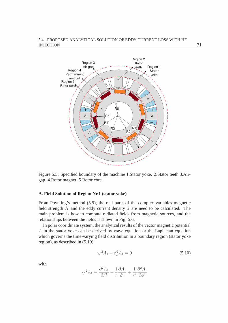
5.4. PROPOSED ANALYTICAL SOLUTION OF EDDY CURRENT LOSS WITHHFINJECTION 71
Figure 5.5: Specified boundary of the machine 1.Stator yoke.2.Stator teeth.3.Air-gap. 4.Rotor magnet. 5.Rotor core.
A. Field Solution of Region Nr.1 (stator yoke)
From Poynting’s method (5.9), the real parts of the complex variables magneticfield strengthH and the eddy current densityJ are need to be calculated. Themain problem is how to compute radiated fields from magnetic sources, and therelationships between the fields is shown in Fig. 5.6.
In polar cooridinate system, the analytical results of the vector magnetic potentialA in the stator yoke can be derived by wave equation or the Laplacian equationwhich governs the time-varying field distribution in a boundary region (stator yokeregion), as described in (5.10).
2A1 + β2ρA1 = 0 (5.10)
with
2A1 =∂2A1
∂r2+
1
r
∂A1
∂r+
1
r2∂2A1
∂φ2
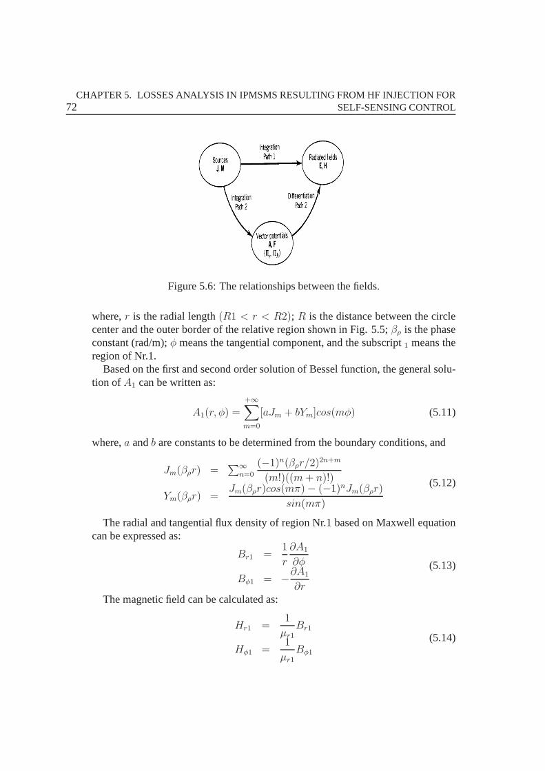
72CHAPTER 5. LOSSES ANALYSIS IN IPMSMS RESULTING FROM HF INJECTION FOR
SELF-SENSING CONTROL
Figure 5.6: The relationships between the fields.
where,r is the radial length(R1 < r < R2); R is the distance between the circlecenter and the outer border of the relative region shown in Fig. 5.5;βρ is the phaseconstant (rad/m);φ means the tangential component, and the subscript1 means theregion of Nr.1.
Based on the first and second order solution of Bessel function, the general solu-tion ofA1 can be written as:
A1(r, φ) =
+∞∑
m=0
[aJm + bYm]cos(mφ) (5.11)
where,a andb are constants to be determined from the boundary conditions, and
Jm(βρr) =∑∞
n=0
(−1)n(βρr/2)2n+m
(m!)((m+ n)!)
Ym(βρr) =Jm(βρr)cos(mπ)− (−1)nJm(βρr)
sin(mπ)
(5.12)
The radial and tangential flux density of region Nr.1 based onMaxwell equationcan be expressed as:
Br1 =1
r
∂A1
∂φ
Bφ1 = −∂A1
∂r
(5.13)
The magnetic field can be calculated as:
Hr1 =1
µr1Br1
Hφ1 =1
µr1
Bφ1
(5.14)

5.4. PROPOSED ANALYTICAL SOLUTION OF EDDY CURRENT LOSS WITHHFINJECTION 73
whereµr1 is the relative permeability of the stator yoke.The boundary conditions are shown in:
Br1|r=R1 = 0
Bφ1|r=R1 = 0(5.15)
B. Field Solution of Region Nr.2 (stator teeth)
Different with region 1, the area of stator teeth can be seen as an area with loss andexcitation source. When the wave equation is used to calculate the vector magneticpotentialA2, the alternative function is described as:
2A2 + β2ρA2 = µr2J2 (5.16)
whereJ2 is the induced eddy current density of stator teeth.The solution ofA2 is:
A2(r, φ) =
+∞∑
m=0
[aJm + bYm]cos(mφ) + E0 (5.17)
where,R2 < r < R3, a andb are constants to be determined from the boundaryconditions;Jm andYm are the same as described in (5.12); one may utilize the waveequation and appropriate boundary conditions to yield a specific solutionE0.
The boundary conditions seen in (5.18) can be used to so the anti-solution forcoefficient in (5.17).
Br1 =1
r
∂A1
∂φ= Br2 =
1
r
∂A2
∂φ
Bφ1 = −∂A1
∂r= Bφ2 = −
∂A2
∂r
(5.18)
One key point of region 2 is the equivalent excitation current density which cantake into account of the space harmonics of the stator MMF dueto stator slottingand the time harmonics due to the non-sinusoidal stator phase current. To achievethe equivalent current density, a proposed solution in [109] is employed, whichintroduces an approximate relationship between the max values of stator windingMMF (Θ (x, t)max) and equivalent excitation stator currentIvmax
, as expressed in:
Θ (x, t)max =2
πIvmax
τpv2
(5.19)
where,Θ (x, t) = Θ (x, t)max cos(vθ) (5.20)

74CHAPTER 5. LOSSES ANALYSIS IN IPMSMS RESULTING FROM HF INJECTION FOR
SELF-SENSING CONTROL
and
Iv(θ) = Ivmaxcos(vθ) (5.21)
where,p is the number of poles,v is the space harmonic orderv = 1, 3, 5, ...,∞,
andτpv = 2πR2
pv.
Based on winding type, the stator winding MMF of IPMSM-2 can be obtained as(5.1), the winding factor for the new 12-slots/10-poles winding with winding coilswith different turns per coil side (Fig. 5.7) can be described as,
vξw,new=n2
n2 + n1[sin(v
π
2)− sin(v
π
3)] +
n2 − n1
n2 + n1sin(v
π
3) (5.22)
Figure 5.7: 12-teeth /10-poles winding topology with different number of turns percoil side. [25]
The equivalent excite current results in:
Iv(θ) =(Θ (x, t) π)
τpv(5.23)
The equivalent excite current density is:
J2 =Iv(θ)
S2(5.24)
where,S2 is the acreage of stator teeth area.

5.4. PROPOSED ANALYTICAL SOLUTION OF EDDY CURRENT LOSS WITHHFINJECTION 75
C. Field Solution of Region Nr.3 (air-gap)
Boundary region Nr.3 is the air-gap area without loss and source-free, and the waveequation (5.26) is used to solveA3.
2A3 + 0 = 0 (5.25)
i.e.∂2A3
∂r2+
1
r
∂A3
∂r+
1
r2∂2A3
∂φ2= 0 (5.26)
where,R3 < r < R4.The general solution ofA3 is:
A3(r, φ) =+∞∑
n=1
+∞∑
m=−∞
[arm + br−m]sin(nωrt + vα+ θu) (5.27)
wherea andb are constants to be determined from the boundary conditions, n is theorder of time harmonic,v is the order of spatial harmonic , andθu is the phase angleof current harmonic.
D. Field Solution of Region Nr.4 (permanent magnet)
Boundary region Nr.4 (R4 < r < R5) is the rotor magnet area with loss and source,and the field solution is the same as that for region Nr.2. However, the analyticalmethod can not get the material properties. Especially based on different frequencythe B-H curve is different. Therefore, the flux density of boundary area Nr.4 needto be corrected by using FEM.
Figure 5.8: A B-H curve for a typical ferromagnetic material[110].
76CHAPTER 5. LOSSES ANALYSIS IN IPMSMS RESULTING FROM HF INJECTION FOR
SELF-SENSING CONTROL
The corrected radial and tangential flux density can be expressed as:
Br4 =1
r
∂A4
∂φ
Bφ4 = −∂A4
∂r
(5.28)
5.5 Summary
Based on the HF injection method, two 12-teeth/10-poles PM machines with dif-ferent windings layer are investigated and their performances are compared. Theanalysis verified that the conventional 12-teeth/10-polesPM machine with double-layer windings has reduced1st, 7th and13th MMF harmonics significantly.
A novel method for reducing the sub-harmonics of the air-gapflux density for thefractional slot tooth (12-teeth/10-poles) concentrated windings using flux barriers instator yoke is presented. Considering the losses, the obtained results show that thenew stator design brings significant advantages of reduced losses over the conven-tional design. The experimental results of the stator current with HF injection signalprove the efficiency improvement of the novel designed machine.
Since the HF injection method is so attractive for self-sensing control of PMSMs,the HF losses need to be researched. Up to now, the HF losses have not beeninvestigated very much and the analytical method has not been applied in this filed.
The analytical solution of the eddy current loss model for IPMSM is proposed inthis chapter. It considers the stator windings type and the non-linear performanceof the permanent magnet. The accuracy of the proposed solution can be improvedby simplified equivalent exciting stator current method andthe iteration of the hys-teresis loop of PM.
For the purpose of finding a balance between the cost of the position encoderand the extra HF losses consumption, the novel machine design is considered. Itis difficult to find a loss minimization control algorithm forHF injection-basedself-sensing control scheme directly. In order to prove theHF losses of the novelmachine are reduced compared with the conventional ones, more analysis and ex-periments need to do in the future.

77
CHAPTER 6
Observer-based Self-sensing Model PredictiveControl of IPMSMs
Although the observer-based self-sensing control techniques are very popular anduniversal, the model predictive control (MPC) schemes are not developed basedon all types of observers. Observer is the key technology fornext generation mo-tor drives. Observer-based state filters are in order to reduce parameter sensitiv-ity. Speed-adaptive full-order observers are, arguably, the most popular schemesbased on the fundamental excitation, due to their accuracy and versatility. Mostadaptive schemes employ the linear time-variable motor model, and are realized asLuenberger observers, sliding mode observers, or Kalman filters. Usually, these ob-servers are realized in a single reference frame and, whatever that frame is, at leastone term of the motor model contains the rotor speed. Thus, the observer must bespeed adaptive.
This chapter will explain how to use the saliency tracking observer for the po-sition & speed estimations, and introduce the Gopinath-style flux linkage observerfor the flux estimation in the model predictive control with finite control set (FCS-MPC) scheme. In implementation, the Gopinath-style observer is considered forobtaining good flux estimation, and the saliency tracking observer can get accurateposition & speed estimations. The experimental results confirm that this controlstrategy has very fast dynamics and it can adapt a very wide speed range and showsgood performance both at transient and steady states.
78CHAPTER 6. OBSERVER-BASED SELF-SENSING MODEL PREDICTIVE CONTROL OF
IPMSMS
6.1 Model Predictive Torque Control with Finite Con-trol Set of IPMSMs
The electromagnetic torque of IPMSMs is given as
Te =3
2P (ψPM iq + (Ld − Lq)idiq) (6.1)
For the IPMSMs the relations between the stator and rotor flux, current, speedand electromagnetic torque can be described as the following ordinary differentialequations (ODEs):
disdt
= L−1s (us − Rsis −
∂Ls
∂θ− jωΨPM) (6.2)
dω
dt=P
J(Te − TL) (6.3)
dθ
dt= ω (6.4)
Internal discrete-time model of the electric drive is necessary, which is used topredict the future evolution of the controlled output variables for a sequence ofcontrol inputs over a prediction horizon (one sampling periodTs). The FCS-MPCis based on the Euler method to predict the flux and electromagnetic torque in theelectric drives, and the forward Euler discretization is shown:
dx
dt=x(k + 1)− x(k)
Ts(6.5)
Omitting the tedious derivation a standard discrete current function of PMSMcan be described as (6.6). The coefficient matrices are described in (6.7), (6.8) and(6.9).
is(k + 1) = Ais(k) +Bus(k) + C (6.6)
where
A =
1−RsTsLd
LqTsωe(k)
Ld
−LdTsωe(k)
Lq
1−RsTsLq
(6.7)
B =
TsLd
0
0TsLq
(6.8)
6.2. GOPINATH-STYLE STATOR FLUX LINKAGE OBSERVER 79
C =
0
−−ψPMTsωe(k)
Lq
(6.9)
Based on the machine model, the stator flux and electrical torque at(k + 1)th
sampling period can be predicted as:
Ψs(k + 1) = Ψs(k) + (us(k)− Rsis(k))Ts (6.10)
Te(k + 1) =3
2P Ψs(k + 1)is(k + 1) (6.11)
Considering the discrete nature of power converters, it is possible to simplifythe optimization problem of MPC by avoiding the use of modulators. Taking intoaccount the finite set of possible switching states of the power converter, whichdepends on the possible combinations of the on/off switching states of the powerswitches, the optimization problem is reduced to the evaluation of all possible statesand the selection of the one which minimizes the given cost function. In addition tothis, if the horizon length is set toN = 1, the calculation of the optimal actuation isvery simple and easy to implement experimentally, as will beshown in this chapter.
The proposed model predictive torque control method is a FCS-MPC methodwhich is designed by pre-considering a torque-band. An appropriate cost functionis defined as following:
g = |T ∗e (k)− Te(k + 1)|+ g||Ψs(k)|
∗ − |Ψs(k + 1)|| (6.12)
whereT ∗e (k) is the reference torque andTe(k + 1) is the predicted electrical torque
for a given switching state,|Ψs(k)|∗ is the reference amplitude for the stator flux,
and|Ψs(k+1)| is the amplitude of the predicted stator flux. The weighting factorgallows one to adjust the importance of the flux error with respect to the torque error.
The optimization method of FCS-MPC focuses on the flux error.Therefore, ac-curate flux estimation is very important to this control scheme. In the conventionalFCS-MPC method, the flux is calculated directly by the equations of discrete ma-chine model. However, IPMSM state equations contain cross-coupling stator fluxlinkage. Flux observer which can do the decoupling is necessary for FCS-MPCtechnology.
6.2 Gopinath-Style Stator Flux Linkage Observer
Since stator flux linkage is not measurable, modified Gopinath-style flux linkageobservers have been developed to estimate stator flux linkage in the continuous
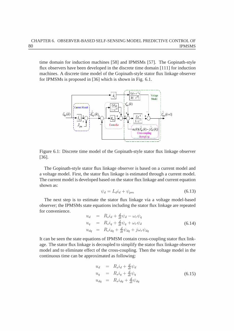
80CHAPTER 6. OBSERVER-BASED SELF-SENSING MODEL PREDICTIVE CONTROL OF
IPMSMS
time domain for induction machines [58] and IPMSMs [57]. TheGopinath-styleflux observers have been developed in the discrete time domain [111] for inductionmachines. A discrete time model of the Gopinath-style stator flux linkage observerfor IPMSMs is proposed in [36] which is shown in Fig. 6.1.
Figure 6.1: Discrete time model of the Gopinath-style stator flux linkage observer[36].
The Gopinath-style stator flux linkage observer is based on acurrent model anda voltage model. First, the stator flux linkage is estimated through a current model.The current model is developed based on the stator flux linkage and current equationshown as:
ψd = Ldid + ψpm (6.13)
The next step is to estimate the stator flux linkage via a voltage model-basedobserver; the IPMSMs state equations including the stator flux linkage are repeatedfor convenience.
ud = Rsid +ddtψd − ωrψq
uq = Rsiq +ddtψq + ωrψd
udq = Rsidq +ddtψdq + jωrψdq
(6.14)
It can be seen the state equations of IPMSM contain cross-coupling stator flux link-age. The stator flux linkage is decoupled to simplify the stator flux linkage observermodel and to eliminate effect of the cross-coupling. Then the voltage model in thecontinuous time can be approximated as following:
ud = Rsid +ddtψd
uq = Rsiq +ddtψq
udq = Rsidq +ddtψdq
(6.15)

6.3. FULL-ORDER LUENBERGER ROTOR POSITION OBSERVER 81
The Gopinath-style stator flux linkage observer utilizes a controller between thecurrent and voltage models. To estimate the stator flux linkage in a discrete timedomain, a discrete time model of the stator flux linkage should be developed seenin Fig. 6.1.
This chapter will combine the Gopinath-style stator flux linkage observer withthe FCS-MPC. The estimated stator flux linkage of the next sampling time is usedas the flux prediction value to solve the optimization problem, which can be seen inFig. 6.7.
6.3 Full-order Luenberger Rotor Position Observer
This section develops an effective self-sensing control ofPMSM drive by using afull-order Luenberger state observer for the rotor position estimation. The observeris based on theαβ stator reference frame dynamic model and no mechanical pa-rameters are involved. Its structure is therefore very simple, and it can be realizedat a low computation burden.
The circuit equation of a IPMSM in theαβ reference frame can be transformedfrom (6.2) in theabc reference frame and results in:
iαβ =1
Lduαβ −
Rs
Ldiαβ − jω(Ld − Lq)iαβ + e0 (6.16)
where
e0 = [ωψPM − (Ld − Lq)1
iq− ω(Ld − Lq)id]e
j(θ+π/2) (6.17)
The state and output equations of IPMSMs are
x = Ax +Bu
y = Cx(6.18)
wherex = [iα iβ ψPMα ψPMβ]
T (6.19)
u = [uα uβ]T (6.20)
y = [iα iβ ]T (6.21)
A =
−Rs
Lq
ωLq
Ld
0 0
−ωLd
Lq−Rs
Lq−ψPM
Lq0
0 0 0 0
0 0 1 0
(6.22)
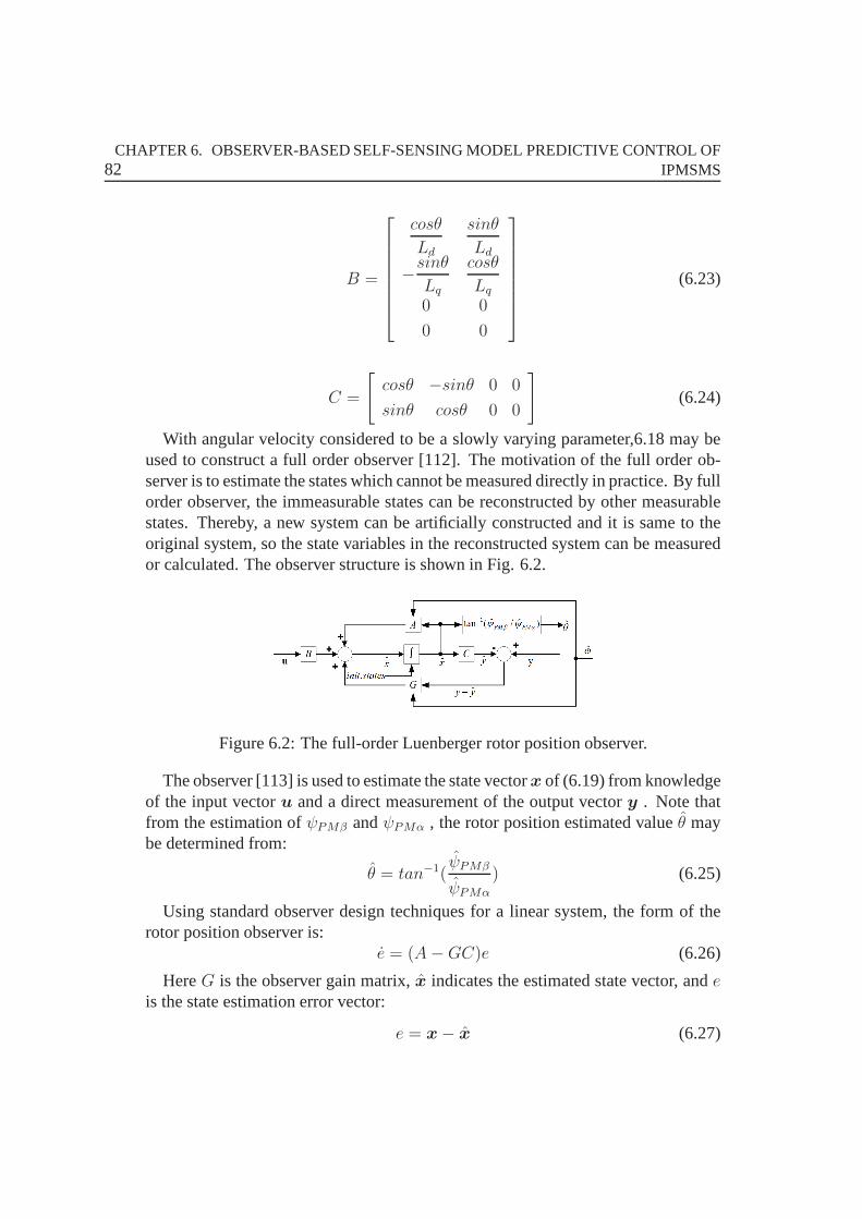
82CHAPTER 6. OBSERVER-BASED SELF-SENSING MODEL PREDICTIVE CONTROL OF
IPMSMS
B =
cosθ
Ld
sinθ
Ld
−sinθ
Lq
cosθ
Lq
0 0
0 0
(6.23)
C =
[cosθ −sinθ 0 0
sinθ cosθ 0 0
](6.24)
With angular velocity considered to be a slowly varying parameter,6.18 may beused to construct a full order observer [112]. The motivation of the full order ob-server is to estimate the states which cannot be measured directly in practice. By fullorder observer, the immeasurable states can be reconstructed by other measurablestates. Thereby, a new system can be artificially constructed and it is same to theoriginal system, so the state variables in the reconstructed system can be measuredor calculated. The observer structure is shown in Fig. 6.2.
Figure 6.2: The full-order Luenberger rotor position observer.
The observer [113] is used to estimate the state vectorx of (6.19) from knowledgeof the input vectoru and a direct measurement of the output vectory . Note thatfrom the estimation ofψPMβ andψPMα , the rotor position estimated valueθ maybe determined from:
θ = tan−1(ψPMβ
ψPMα
) (6.25)
Using standard observer design techniques for a linear system, the form of therotor position observer is:
e = (A−GC)e (6.26)
HereG is the observer gain matrix,x indicates the estimated state vector, andeis the state estimation error vector:
e = x− x (6.27)
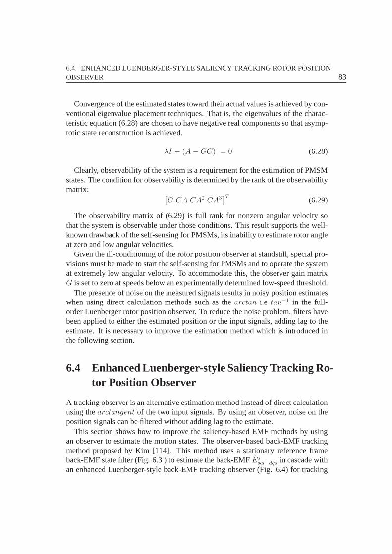
6.4. ENHANCED LUENBERGER-STYLE SALIENCY TRACKING ROTOR POSITIONOBSERVER 83
Convergence of the estimated states toward their actual values is achieved by con-ventional eigenvalue placement techniques. That is, the eigenvalues of the charac-teristic equation (6.28) are chosen to have negative real components so that asymp-totic state reconstruction is achieved.
|λI − (A−GC)| = 0 (6.28)
Clearly, observability of the system is a requirement for the estimation of PMSMstates. The condition for observability is determined by the rank of the observabilitymatrix: [
C CA CA2 CA3]T
(6.29)
The observability matrix of (6.29) is full rank for nonzero angular velocity sothat the system is observable under those conditions. This result supports the well-known drawback of the self-sensing for PMSMs, its inabilityto estimate rotor angleat zero and low angular velocities.
Given the ill-conditioning of the rotor position observer at standstill, special pro-visions must be made to start the self-sensing for PMSMs and to operate the systemat extremely low angular velocity. To accommodate this, theobserver gain matrixG is set to zero at speeds below an experimentally determined low-speed threshold.
The presence of noise on the measured signals results in noisy position estimateswhen using direct calculation methods such as thearctan i.e tan−1 in the full-order Luenberger rotor position observer. To reduce the noise problem, filters havebeen applied to either the estimated position or the input signals, adding lag to theestimate. It is necessary to improve the estimation method which is introduced inthe following section.
6.4 Enhanced Luenberger-style Saliency Tracking Ro-tor Position Observer
A tracking observer is an alternative estimation method instead of direct calculationusing thearctangent of the two input signals. By using an observer, noise on theposition signals can be filtered without adding lag to the estimate.
This section shows how to improve the saliency-based EMF methods by usingan observer to estimate the motion states. The observer-based back-EMF trackingmethod proposed by Kim [114]. This method uses a stationary reference frameback-EMF state filter (Fig. 6.3 ) to estimate the back-EMFEs
sal−dqs in cascade withan enhanced Luenberger-style back-EMF tracking observer (Fig. 6.4) for tracking
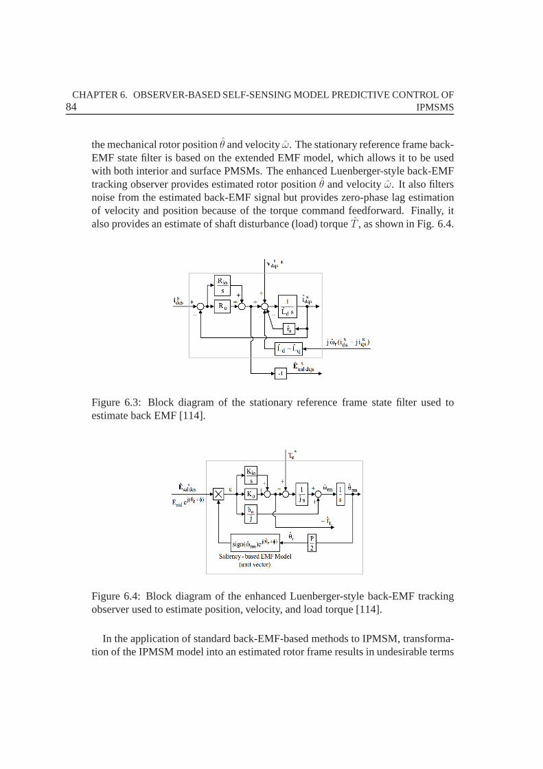
84CHAPTER 6. OBSERVER-BASED SELF-SENSING MODEL PREDICTIVE CONTROL OF
IPMSMS
the mechanical rotor positionθ and velocityω. The stationary reference frame back-EMF state filter is based on the extended EMF model, which allows it to be usedwith both interior and surface PMSMs. The enhanced Luenberger-style back-EMFtracking observer provides estimated rotor positionθ and velocityω. It also filtersnoise from the estimated back-EMF signal but provides zero-phase lag estimationof velocity and position because of the torque command feedforward. Finally, italso provides an estimate of shaft disturbance (load) torque T , as shown in Fig. 6.4.
Figure 6.3: Block diagram of the stationary reference framestate filter used toestimate back EMF [114].
Figure 6.4: Block diagram of the enhanced Luenberger-styleback-EMF trackingobserver used to estimate position, velocity, and load torque [114].
In the application of standard back-EMF-based methods to IPMSM, transforma-tion of the IPMSM model into an estimated rotor frame resultsin undesirable terms
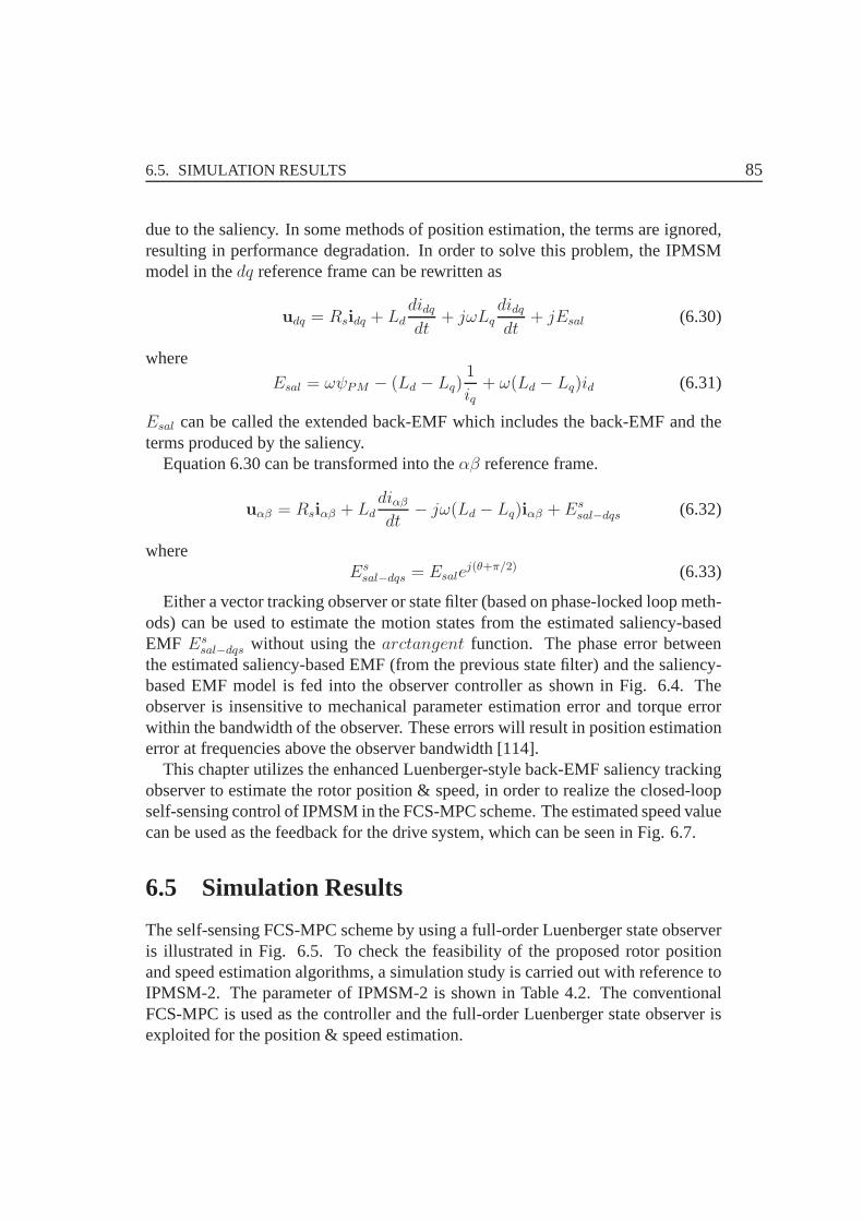
6.5. SIMULATION RESULTS 85
due to the saliency. In some methods of position estimation,the terms are ignored,resulting in performance degradation. In order to solve this problem, the IPMSMmodel in thedq reference frame can be rewritten as
udq = Rsidq + Lddidqdt
+ jωLqdidqdt
+ jEsal (6.30)
where
Esal = ωψPM − (Ld − Lq)1
iq+ ω(Ld − Lq)id (6.31)
Esal can be called the extended back-EMF which includes the back-EMF and theterms produced by the saliency.
Equation 6.30 can be transformed into theαβ reference frame.
uαβ = Rsiαβ + Lddiαβdt
− jω(Ld − Lq)iαβ + Essal−dqs (6.32)
whereEs
sal−dqs = Esalej(θ+π/2) (6.33)
Either a vector tracking observer or state filter (based on phase-locked loop meth-ods) can be used to estimate the motion states from the estimated saliency-basedEMF Es
sal−dqs without using thearctangent function. The phase error betweenthe estimated saliency-based EMF (from the previous state filter) and the saliency-based EMF model is fed into the observer controller as shown in Fig. 6.4. Theobserver is insensitive to mechanical parameter estimation error and torque errorwithin the bandwidth of the observer. These errors will result in position estimationerror at frequencies above the observer bandwidth [114].
This chapter utilizes the enhanced Luenberger-style back-EMF saliency trackingobserver to estimate the rotor position & speed, in order to realize the closed-loopself-sensing control of IPMSM in the FCS-MPC scheme. The estimated speed valuecan be used as the feedback for the drive system, which can be seen in Fig. 6.7.
6.5 Simulation Results
The self-sensing FCS-MPC scheme by using a full-order Luenberger state observeris illustrated in Fig. 6.5. To check the feasibility of the proposed rotor positionand speed estimation algorithms, a simulation study is carried out with reference toIPMSM-2. The parameter of IPMSM-2 is shown in Table 4.2. The conventionalFCS-MPC is used as the controller and the full-order Luenberger state observer isexploited for the position & speed estimation.
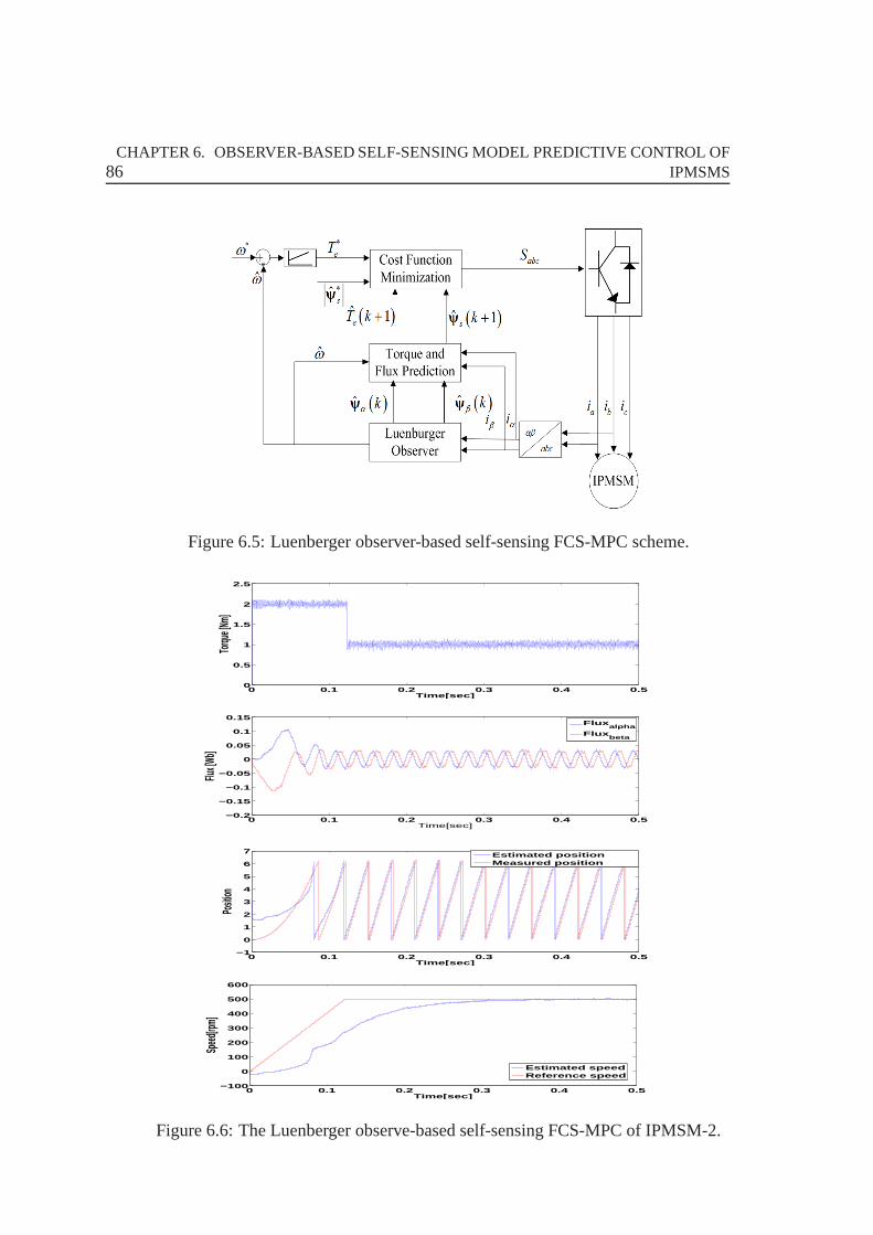
86CHAPTER 6. OBSERVER-BASED SELF-SENSING MODEL PREDICTIVE CONTROL OF
IPMSMS
Figure 6.5: Luenberger observer-based self-sensing FCS-MPC scheme.
0 0.1 0.2 0.3 0.4 0.50
0.5
1
1.5
2
2.5
Time[sec]
Torqu
e [Nm]
0 0.1 0.2 0.3 0.4 0.5−0.2
−0.15
−0.1
−0.05
0
0.05
0.1
0.15
Time[sec]
Flux [W
b]
Fluxalpha
Fluxbeta
0 0.1 0.2 0.3 0.4 0.5−1
0
1
2
3
4
5
6
7
Time[sec]
Positi
on
Estimated positionMeasured position
0 0.1 0.2 0.3 0.4 0.5−100
0
100
200
300
400
500
600
Time[sec]
Speed
[rpm]
Estimated speedReference speed
Figure 6.6: The Luenberger observe-based self-sensing FCS-MPC of IPMSM-2.
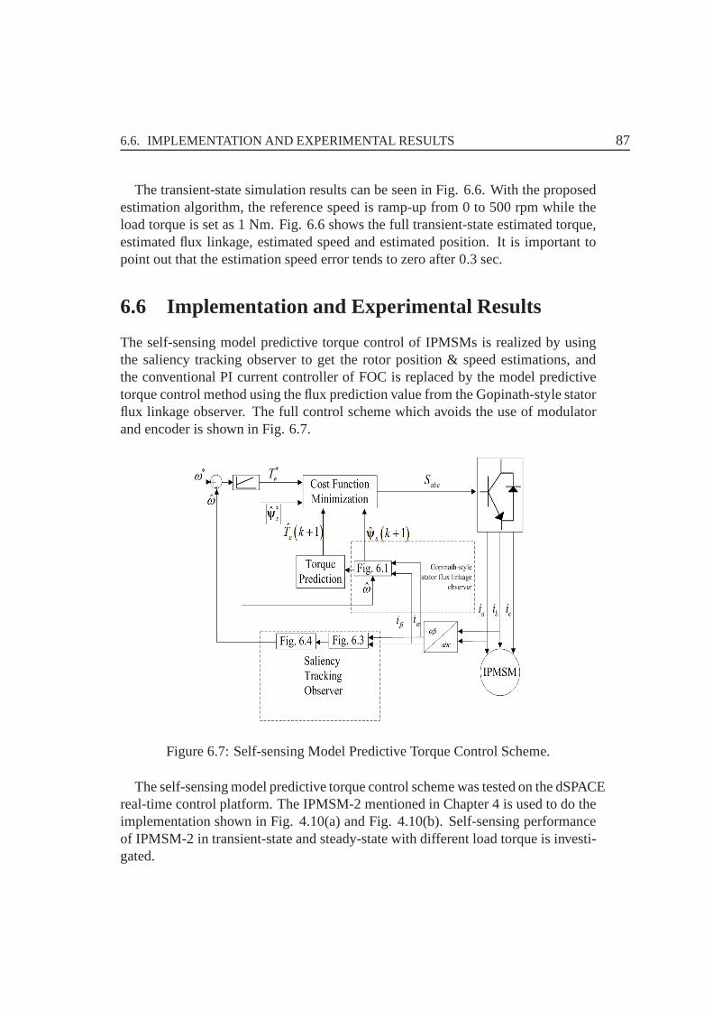
6.6. IMPLEMENTATION AND EXPERIMENTAL RESULTS 87
The transient-state simulation results can be seen in Fig. 6.6. With the proposedestimation algorithm, the reference speed is ramp-up from 0to 500 rpm while theload torque is set as 1 Nm. Fig. 6.6 shows the full transient-state estimated torque,estimated flux linkage, estimated speed and estimated position. It is important topoint out that the estimation speed error tends to zero after0.3 sec.
6.6 Implementation and Experimental Results
The self-sensing model predictive torque control of IPMSMsis realized by usingthe saliency tracking observer to get the rotor position & speed estimations, andthe conventional PI current controller of FOC is replaced bythe model predictivetorque control method using the flux prediction value from the Gopinath-style statorflux linkage observer. The full control scheme which avoids the use of modulatorand encoder is shown in Fig. 6.7.
Figure 6.7: Self-sensing Model Predictive Torque Control Scheme.
The self-sensing model predictive torque control scheme was tested on the dSPACEreal-time control platform. The IPMSM-2 mentioned in Chapter 4 is used to do theimplementation shown in Fig. 4.10(a) and Fig. 4.10(b). Self-sensing performanceof IPMSM-2 in transient-state and steady-state with different load torque is investi-gated.
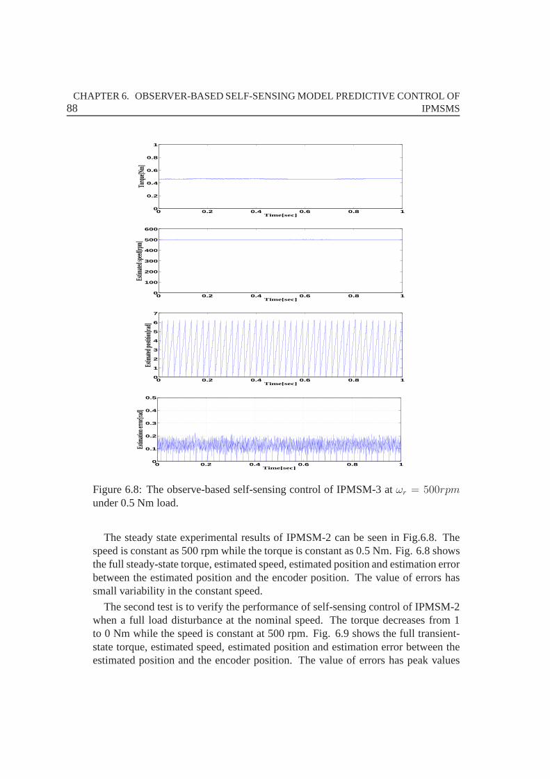
88CHAPTER 6. OBSERVER-BASED SELF-SENSING MODEL PREDICTIVE CONTROL OF
IPMSMS
0 0.2 0.4 0.6 0.8 10
0.2
0.4
0.6
0.8
1
Time[sec]
Torqu
e[Nm]
0 0.2 0.4 0.6 0.8 10
100
200
300
400
500
600
Time[sec]
Estim
ated s
peed
[rpm]
0 0.2 0.4 0.6 0.8 10
1
2
3
4
5
6
7
Time[sec]
Estim
ated p
ostitio
n[rad
]
0 0.2 0.4 0.6 0.8 10
0.1
0.2
0.3
0.4
0.5
Time[sec]
Estim
ation e
rror[ra
d]
Figure 6.8: The observe-based self-sensing control of IPMSM-3 at ωr = 500rpmunder 0.5 Nm load.
The steady state experimental results of IPMSM-2 can be seenin Fig.6.8. Thespeed is constant as 500 rpm while the torque is constant as 0.5 Nm. Fig. 6.8 showsthe full steady-state torque, estimated speed, estimated position and estimation errorbetween the estimated position and the encoder position. The value of errors hassmall variability in the constant speed.
The second test is to verify the performance of self-sensingcontrol of IPMSM-2when a full load disturbance at the nominal speed. The torquedecreases from 1to 0 Nm while the speed is constant at 500 rpm. Fig. 6.9 shows the full transient-state torque, estimated speed, estimated position and estimation error between theestimated position and the encoder position. The value of errors has peak values
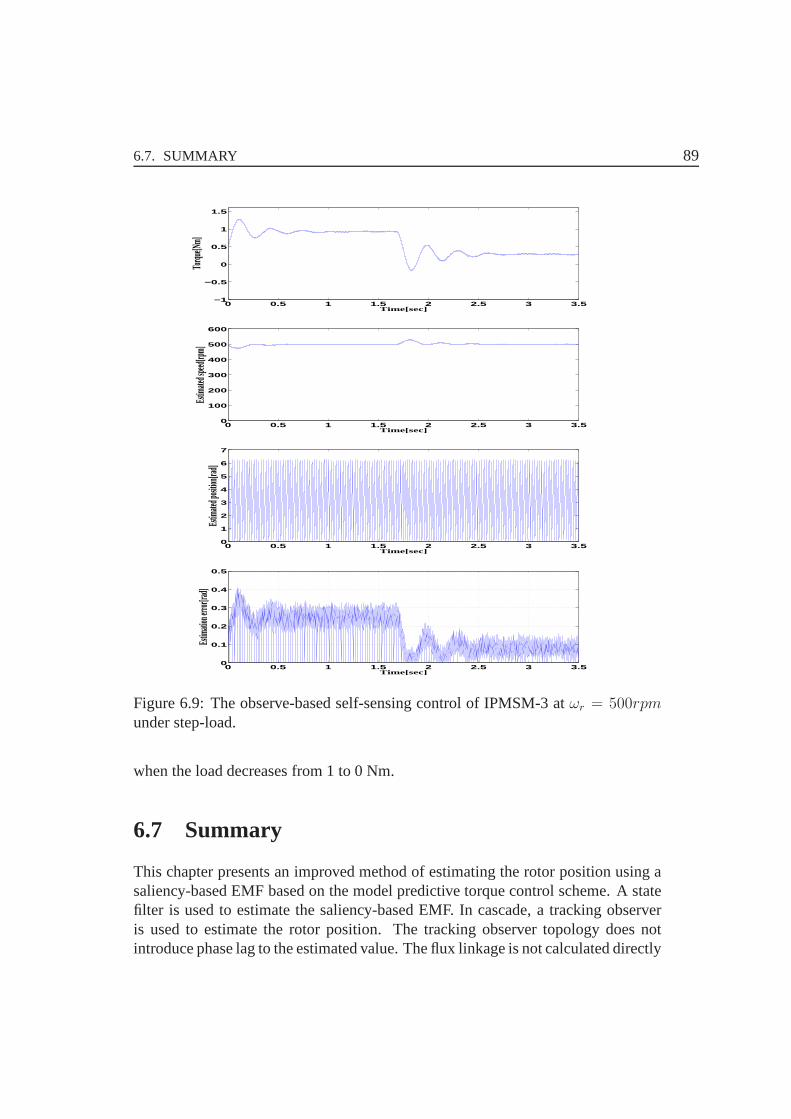
6.7. SUMMARY 89
0 0.5 1 1.5 2 2.5 3 3.5−1
−0.5
0
0.5
1
1.5
Time[sec]
Torqu
e[Nm]
0 0.5 1 1.5 2 2.5 3 3.50
100
200
300
400
500
600
Time[sec]
Estim
ated s
peed
[rpm]
0 0.5 1 1.5 2 2.5 3 3.50
1
2
3
4
5
6
7
Time[sec]
Estim
ated p
osition
[rad]
0 0.5 1 1.5 2 2.5 3 3.50
0.1
0.2
0.3
0.4
0.5
Time[sec]
Estim
ation e
rror[ra
d]
Figure 6.9: The observe-based self-sensing control of IPMSM-3 at ωr = 500rpmunder step-load.
when the load decreases from 1 to 0 Nm.
6.7 Summary
This chapter presents an improved method of estimating the rotor position using asaliency-based EMF based on the model predictive torque control scheme. A statefilter is used to estimate the saliency-based EMF. In cascade, a tracking observeris used to estimate the rotor position. The tracking observer topology does notintroduce phase lag to the estimated value. The flux linkage is not calculated directly

90CHAPTER 6. OBSERVER-BASED SELF-SENSING MODEL PREDICTIVE CONTROL OF
IPMSMS
by the equations of discrete machine model in the FCS-MPC scheme, which isestimated by the Gopinath-style stator flux linkage observer. The following pointssummarize the work presented.
• The model predictive torque control of IPMSMs is introduced.
• The full-order Luenburger rotor position observer is explicated based on acontinuous IPMSM model.
• The Gopinath-style stator flux linkage observer based on a discrete IPMSMmodel is used to provide estimated flux value in the FCS-MPC scheme.
• The enhanced Luenberger-style back-EMF tracking observeris implementedto estimate the rotor position and velocity.
91
CHAPTER 7
Conclusions and Future Work
7.1 Conclusions
Self-sensing control of PMSMs has been very popular in the industry for many yearsand it still has space to do performance improvements. This thesis is focus on theself-sensing control topic and demonstrate the state-of-the -art review in Chapter 2.
In Chapter 3, the mathematical model of PMSMs is introduced firstly. Secondly,the high-frequency model of the surface-mounted PMSMs is built. There are mainlytwo kinds of high-frequency injection methods: rotating and pulsating vector injec-tion. Both methods are elaborated. Furthermore, the advantages and disadvantageare discussed. The implementation and experiments are doneby an commercialSPMSM. The experimental results show the high frequency injection method hasgood estimation performance at very low & zero speed.
In chapter 4, two novel interior PMSMs are introduced and areapplied to do theself-sensing control strategy. At first the machine design and the IPMSMs modelare present. Secondly, the IPMSMs model with high-frequency is built. There aremany effects will decrease the estimation accuracy: saliency, cross Saturation, highfrequency inductance, high frequency resistance and harmonic distortion. All thepossible reasons based on the two novel IPMSMs are analyzed in this chapter. Theimplementation and experiments are done by using the conventional high frequencyrotating vector injection method. It proved that the novel IPMSMs have very highestimation accuracy.
In chapter 5, the new stator topology of IPMSM-2 is demonstrated. Firstly, lossesin this IPMSM-2 resulting from high frequency injection forself-sensing control isanalyzed by MMF calculated. Secondly, the high frequency losses are analyzed
92 CHAPTER 7. CONCLUSIONS AND FUTURE WORK
by the currents harmonics from the experimental results of injection-based self-sensing control of IPMSM-2. Finally, the new high frequencylosses analyticalmethod based on Poynting’s theorem is proposed in this chapter. It will take a shortcomputational time to calculate the HF losses by the analytical method.
In chapter 6, the self-sensing control of PMSMs is implemented using the back-EMF at medium and high speed. Firstly, the conventional model predictive torquecontrol method is introduced, which is an alternative control method from FOC andDTC. Secondly, the Gopinath-style stator flux linkage observer is applied to do theflux estimation in the model predictive torque control scheme. Thirdly, the full-order Luenberger rotor position observer is built and the simulation results can beseen in this chapter. The enhanced Luenberger-style saliency tracking rotor positionobserver is achieved by calculating the back-EMF. Finally,the implementation andexperiments are done based on the conventional model predictive torque controlmethod, and the Gopinath-style stator flux linkage observeris realized to do theflux estimation, and the enhanced Luenberger-style saliency tracking rotor positionobserver is completed the self-sensing control.
The conclusion and the recommended future work is shown in this chapter 7.
7.2 Recommended Future Work
Based on the work presented, the following topics have been identified for furtherinvestigation:
• Integration of the saliency-based high frequency injection self-sensing methodinto the low switching frequency MPC with continuous control set.
Since MPC with continuous control set achieves desired torque and stator fluxwith constant switching frequency, the high frequency injection-based self-sensingmethod can be integrated into MPC with continuous control set. For high switchingfrequency operation, the frequency of injected voltage hasa wide range of options.In contrast, for low switching frequency operation, the frequency of the injectedsinusoidal voltage needs to be set low to ensure enough points for one cycle of theinjected sinusoidal voltage. However, a torque pulsation will be introduced whenthe injected voltage has the frequency compatible to the fundamental frequency.Thus, the PWM switching frequency signal injection based self-sensing methodshould be integrated to the low switching frequency MPC to achieve desired torqueand flux without position sensor. The performance of the low switching frequency,self-sensing, MPC with continuous control set needs to be investigated for bothnormal and deep field weakening operation with low switchingfrequencies.

7.2. RECOMMENDED FUTURE WORK 93
• Evaluation of the power losses generated from different high frequency injec-tion methods.
In this thesis, the calculation of losses from high frequency injection effects isproposed by a new analytical method, however, in order to getthe accurate resultsmore research need to do. Saliency-based self-sensing method can be implementedbased on either rotating or pulsating high frequency voltage injection. Lots of pa-pers have been published on comparison of different injection methods in terms ofthe position estimation accuracy. However, the power losses from different high fre-quency injection methods have not been discussed or investigated. Since dynamicloss modeling has the capability of capturing the dynamic loss generated from thehigh frequency voltage injection in self-sensing methods,it should be utilized toevaluate the performance of different injection methods, such as sinusoidal waveinjection and square wave injection, in terms of power losses.
• Investigation of different flux observers can be used in the conventional modelpredictive torque control method.
Flux observer is the key point of the electric drives and not very popular used inthe FCS-MPC scheme. This thesis proposes a Gopinath-Style observer for the fluxestimation in IPMSM under both steady state and transient operations. It wouldbe better if this observer be changed to such as sliding mode observers, or Kalmanfilters, in order to find a optimization solution of the most accurate flux estimation.
• Investigation of excess loss and rotor loss based on FEM for different classesof electrical machines.
In this thesis, the stator iron losses, rotor iron losses andthe magnet eddy currentlosses of IPMSM-2 based on FEM is shown. However, the excess loss and therotor loss due to the leakage flux are not taken into account. The experimentallyestimated iron loss coefficients can partially cover the excess loss and rotor loss.However, the detailed investigation of these losses has notbeen performed. FEMcould be a good method to investigate the both losses for different machines.

94 CHAPTER 7. CONCLUSIONS AND FUTURE WORK

95
APPENDIX A
List of Nomenclature and Abbreviations
A.1 Nomenclature
The following list only contains relevant symbols and bold symbol means spacevector.
i, I current space vectoru voltage space vectorΨ flux linkage space vectorR resistanceL inductanceθ rotor position angleδ current load angleω speedN number of turns per coilP pole pair number or powerΘ magnetomotive forceJ induced current densityA magnetic vector potentialB flux densityr, R radial lengthTe electromagnetic torqueTL load torqueTs sample period

96 APPENDIX A. LIST OF NOMENCLATURE AND ABBREVIATIONS
The following list only contains relevant subscripts.
ˆ estimated quantity˙ time derivative operatord/dt∗ reference quantitys statorr rotorc carrier (injection) signalsα, β stator fixed Cartesian axisd, q rotor fixed direct and quadrature axisΣ,∆ mean and difference valuep, n positive and negative directionw1, w2 winding system 1 and 2 of IPMSM-3pm,mag permanent-magneteddy eddy-currenthyst hysteresis

A.2. ABBREVIATIONS 97
A.2 Abbreviations
PMSMs Permanent magnet synchronous machinesSPMSMs Surface-mounted permanent magnet synchronous machinesIPMSMs Interior permanent magnet synchronous machinesCW Concentrated windingsDW Distributed windingsHF High frequencyFEM Finite element methodsMMF Magnetomotive forceFFT Fast Fourier transformFS Fractional slotCFF Command feed-forwardEMF Electromotive ForceMRAS Model reference adaptive systemPWM Pulse width modulationSVM Space vector modulationFLC Fuzzy logic controlDTC Direct torque controlFOC Field-Oriented ControlDB-DTFC Deadbeat-direct torque and flux controlPID Proportional-integral-derivativeLMC Loss model controlFCS-MPC Model predictive control with finite control set

98 APPENDIX A. LIST OF NOMENCLATURE AND ABBREVIATIONS

99
APPENDIX B
List of Publications
B.1 Published Conference Papers
• Xiaocan Wang, R. Kennel, Zhixun Ma and Jianbo Gao, ”Analysisof permanent-magnet machine for sensorless control based on high-frequency signal injec-tion,” Power Electronics and Motion Control Conference (IPEMC), 2012 7thInternational , vol.4, pp.2367,2371, 2-5 June 2012.
• Xiaocan Wang, Wei Xie, R. Kennel and D. Gerling, ”Sensorlesscontrol ofa novel IPMSM based on high-frequency injection,” Power Electronics andApplications (EPE), 2013 15th European Conference on , pp.1,8, 2-6 Sept.2013.
• Wei Xie, Xiaocan Wang, G. Dajaku, D. Gerling and R. Kennel, ”Improvementand comparison of efficiency and low cost drive system based on DTC andDTC-SVM,” Electric Machines & Drives Conference (IEMDC), 2013 IEEEInternational , pp.1261,1266, 12-15 May 2013.
• Wei Xie, Fengxiang Wang, Xiaocan Wang, G. Dajaku, D. Gerlingand R.Kennel, ”Analysis of high efficiency and low cost drive system of IPMSM byusing two-steps model predictive torque control,” ControlConference (CCC),2013 32nd Chinese, pp.4114,4119, 26-28 July 2013.
• Wei Xie, Xiaocan Wang, G. Dajaku, D. Gerling and R. Kennel, ”Analysisand improvement of high efficiency and low cost drive system based on di-rect torque control,” Power Electronics and Applications (EPE), 2013 15thEuropean Conference on, pp.1,10, 2-6 Sept. 2013.
• Xiaocan Wang, R. Kennel, Wei Xie and D. Gerling, ”Analysis oflosses in anovel IPMSM resulting from high-frequency injection for sensorless control,”
100 APPENDIX B. LIST OF PUBLICATIONS
Sensorless Control for Electrical Drives and Predictive Control of ElectricalDrives and Power Electronics (SLED/PRECEDE), 2013 IEEE InternationalSymposium on, pp.1,5, 17-19 Oct. 2013.
B.2 Published Journal Papers
• Xiaocan Wang, Wei Xie, G. Dajaku, R. Kennel, D. Gerling and R.D. Lorenz,”Position Self-Sensing Evaluation of Novel CW-IPMSMs witha HF Injec-tion Method,” Industry Applications, IEEE Transactions on, vol.50, no.5,pp.3325,3334, Sept.-Oct. 2014
B.3 Submitted Journal Papers
• Wei Xie, Xiaocan Wang, Fengxiang Wang, D. Gerling and R. Kennel, ”Dy-namic Loss Minimization of Finite Control Set Model Predictive Torque Con-trol for Electric Drive System,” IEEE Transactions on PowerElectronics.
• Wei Xie, Xiaocan Wang, Fengxiang Wang, Wei Xu, D. Gerling, R.Kenneland R. D. Lorenz,, ”Deadbeat Model Predictive Torque Control for Perma-nent Magnet Synchronous Machines,” IEEE Transactions on Industrial Elec-tronics.
BIBLIOGRAPHY 101
Bibliography
[1] D. Novotny, T. Lipo, and T.M.Jahns,Introduction to electric machines andDrives. WisPERC Administrator, 2009.
[2] P. Guglielmi, M. Pastorelli, G. Pellegrino, and A. Vagati, “Position-sensorless control of permanent-magnet-assisted synchronous reluctancemotor,” Industry Applications, IEEE Transactions on, vol. 40, no. 2, pp. 615–622, 2004.
[3] D. Novotny and T. Lipo,Vector Control and Dynamics of AC Drives. NewYork: Oxford Univ, 1996.
[4] A. Faggion, E. Fornasiero, N. Bianchi, and S. Bolognani,“Sensorless capa-bility of fractional-slot surface-mounted PM motors,”Industry Applications,IEEE Transactions on, vol. 49, no. 3, pp. 1325–1332, 2013.
[5] C.-Y. Yu, J. Tamura, D. Reigosa, and R. Lorenz, “Positionself-sensing eval-uation of a FI-IPMSM based on high-frequency signal injection methods,”Industry Applications, IEEE Transactions on, vol. 49, no. 2, pp. 880–888,2013.
[6] L. A. S. Ribeiro, M. Degner, F. Briz, and R. Lorenz, “Comparison of car-rier signal voltage and current injection for the estimation of flux angle orrotor position,” inIndustry Applications Conference, 1998. Thirty-Third IASAnnual Meeting. The 1998 IEEE, vol. 1, 1998, pp. 452–459.
[7] M. Linke, R. Kennel, and J. Holtz, “Sensorless speed and position controlof synchronous machines using alternating carrier injection,” in Electric Ma-chines and Drives Conference, 2003. IEMDC’03. IEEE International, vol. 2,2003, pp. 1211–1217 vol.2.
102 BIBLIOGRAPHY
[8] R. Wu and G. Slemon, “A permanent magnet motor drive without a shaftsensor,” inIndustry Applications Society Annual Meeting, vol. 1, 1990, pp.553–558.
[9] E. Robeischl, M. Schroedl, and M. Krammer, “Position-sensorless biaxialposition control with industrial PM motor drives based on INFORM- andback EMF model,” inIECON 02 Industrial Electronics Society, IEEE 200228th Annual Conference of the, vol. 1, 2002, pp. 668–673.
[10] A. Eilenberger and M. Schroedl, “Extended back EMF model for PM syn-chronous machines with different inductances in d- and q-axis,” in PowerElectronics and Motion Control Conference, 2008. EPE-PEMC 2008. 13th,2008, pp. 945–948.
[11] Freescale, “Sensorless PMSM Vector Control with a Sliding Mode Observerfor Compressors Using MC56F8013,” Freescale Semiconductor, Tech. Rep.,09/2008.
[12] M. Corley and R. Lorenz, “Rotor position and velocity estimation for asalient-pole permanent magnet synchronous machine at standstill and highspeeds,”Industry Applications, IEEE Transactions on, vol. 34, no. 4, pp.784–789, 1998.
[13] R. Kennel, “Encoderless control of synchronous machines with permanentmagnets - impact of magnetic design,” inOptimization of Electrical andElectronic Equipment (OPTIM), 2010 12th International Conference on,2010, pp. 19–24.
[14] F. Briz, M. Degner, A. Diez, and R. Lorenz, “Measuring, modeling, anddecoupling of saturation-induced saliencies in carrier-signal injection-basedsensorless ac drives,”Industry Applications, IEEE Transactions on, vol. 37,no. 5, pp. 1356–1364, 2001.
[15] ——, “Static and dynamic behavior of saturation-induced saliencies and theireffect on carrier-signal-based sensorless AC drives,”Industry Applications,IEEE Transactions on, vol. 38, no. 3, pp. 670–678, 2002.
[16] P. Garcia, F. Briz, M. Degner, and D. Diaz-Reigosa, “Accuracy, bandwidth,and stability limits of carrier-signal-injection-based sensorless control meth-ods,” Industry Applications, IEEE Transactions on, vol. 43, no. 4, pp. 990–1000, 2007.
BIBLIOGRAPHY 103
[17] Z. Zhu, Y. Li, D. Howe, and C. Bingham, “Compensation forrotor positionestimation error due to cross-coupling magnetic saturation in signal injectionbased sensorless control of PM brushless AC motors,” inElectric MachinesDrives Conference, 2007. IEMDC ’07. IEEE International, vol. 1, 2007, pp.208–213.
[18] M. Zeraoulia, M. Benbouzid, and D. Diallo, “Electric motor drive selectionissues for HEV propulsion systems: A comparative study,”Vehicular Tech-nology, IEEE Transactions on, vol. 55, no. 6, pp. 1756–1764, 2006.
[19] Control of permanent magnet synchronous motors for au-tomotive applications. [Online]. Available: http://wwwlea.uni-paderborn.de/forschung/pmsm-control.html
[20] G. Dajaku, “Electromagnetic and thermal modeling of highly utilized PMmachines,” Ph.D. dissertation, University of Federal Defense Munich, 2006.
[21] Optimising new motor designs for electric vehicle. [Online]. Available:http://www.dpaonthenet.net/article/62178
[22] D. Ishak, Z. Zhu, and D. Howe, “Comparison of PM brushless motors, havingeither all teeth or alternate teeth wound,”Energy Conversion, IEEE Transac-tions on, vol. 21, no. 1, pp. 95–103, 2006.
[23] N. Bianchi and E. Fornasiero, “Index of rotor losses in three-phase fractional-slot permanent magnet machines,”Electric Power Applications, IET, vol. 3,no. 5, pp. 381–388, 2009.
[24] G. Dajaku and D. Gerling, “Magnetic radial force density of the PM machinewith 12-teeth/10-poles winding topology,” inElectric Machines and DrivesConference, 2009. IEMDC ’09. IEEE International, 2009, pp. 1715–1720.
[25] ——, “Eddy current loss minimization in rotor magnets ofPM machinesusing high-efficiency 12-teeth/10-slots winding topology,” in Electrical Ma-chines and Systems (ICEMS), 2011 International Conference on, 2011, pp.1–6.
[26] ——, “A novel 24-slots/10-poles winding topology for electric machines,” inElectric Machines Drives Conference (IEMDC), 2011 IEEE International,2011, pp. 65–70.
104 BIBLIOGRAPHY
[27] ——, “A novel 12-teeth/10-poles PM machine with flux barriers in statoryoke,” in Electrical Machines (ICEM), 2012 XXth International Conferenceon, 2012, pp. 36–40.
[28] E. Fornasiero, L. Alberti, N. Bianchi, and S. Bolognani, “Considerationson selecting fractional-slot nonoverlapped coil windings,” Industry Applica-tions, IEEE Transactions on, vol. 49, no. 3, pp. 1316–1324, 2013.
[29] G. Dajaku, “Elektrische maschine,” Patent DE 102 008 054 284 A1.
[30] G. Dajaku and D. Gerling, “A novel tooth concentrated winding withlow space harmonic contents,” inElectric Machines Drives Conference(IEMDC), 2013 IEEE International, 2013, pp. 755–760.
[31] L. Xu and S. Li, “Torque control patching and anti-windup and bumplesstransfer conditioning of current regulators for high-speed PMSM systems,”in Power Electronics Specialists Conference, 2001. PESC. 2001 IEEE 32ndAnnual, vol. 3, 2001, pp. 1679–1682 vol. 3.
[32] J. Holtz, W. Lotzkat, and A. Khambadkone, “On continuous control of PWMinverters in the overmodulation range including the six-step mode,”PowerElectronics, IEEE Transactions on, vol. 8, no. 4, pp. 546–553, 1993.
[33] J. Jung and K. Nam, “A dynamic decoupling control schemefor high-speedoperation of induction motors,”Industrial Electronics, IEEE Transactionson, vol. 46, no. 1, pp. 100–110, 1999.
[34] I. Takahashi and T. Noguchi, “A new quick-response and high-efficiency con-trol strategy of an induction motor,”Industry Applications, IEEE Transac-tions on, vol. IA-22, no. 5, pp. 820–827, 1986.
[35] I. Takahashi and Y. Ohmori, “High-performance direct torque control ofan induction motor,”Industry Applications, IEEE Transactions on, vol. 25,no. 2, pp. 257–264, 1989.
[36] J. S. Lee, C.-H. Choi, J.-K. Seok, and R. Lorenz, “Deadbeat-direct torqueand flux control of interior permanent magnet synchronous machines withdiscrete time stator current and stator flux linkage observer,” Industry Appli-cations, IEEE Transactions on, vol. 47, no. 4, pp. 1749–1758, 2011.
[37] T. Habetler, F. Profumo, M. Pastorelli, and L. Tolbert,“Direct torque con-trol of induction machines using space vector modulation,”Industry Appli-cations, IEEE Transactions on, vol. 28, no. 5, pp. 1045–1053, 1992.
BIBLIOGRAPHY 105
[38] G. Escobar, A. Stankovic, E. Galvan, J. Carrasco, and R.Ortega, “A familyof switching control strategies for the reduction of torqueripple in DTC,”Control Systems Technology, IEEE Transactions on, vol. 11, no. 6, pp. 933–939, 2003.
[39] L. Zhong, M. Rahman, W. Y. Hu, and K. W. Lim, “Analysis of direct torquecontrol in permanent magnet synchronous motor drives,”Power Electronics,IEEE Transactions on, vol. 12, no. 3, pp. 528–536, 1997.
[40] H. Ziane, J.-M. Retif, and T. Rekioua, “Fixed-switching-frequency DTC con-trol for PM synchronous machine with minimum torque ripples,” Electricaland Computer Engineering, Canadian Journal of, vol. 33, no. 3/4, pp. 183–189, 2008.
[41] R. Lorenz, “The emerging role of dead-beat, direct torque and flux controlin the future of induction machine drives,” inOptimization of Electrical andElectronic Equipment, 2008. OPTIM 2008. 11th International Conferenceon, 2008, pp. XIX–XXVII.
[42] D. Reigosa, P. Garcia, D. Raca, F. Briz, and R. Lorenz, “Measurement andadaptive decoupling of cross-saturation effects and secondary saliencies insensorless controlled IPM synchronous machines,”Industry Applications,IEEE Transactions on, vol. 44, no. 6, pp. 1758–1767, 2008.
[43] J. Urresty, J. Riba, and L. Romeral, “A back-EMF based method to detectmagnet failures in PMSMs,”Magnetics, IEEE Transactions on, vol. 49, no. 1,pp. 591–598, 2013.
[44] Z. Wang, K. Lu, and F. Blaabjerg, “A simple startup strategy based oncurrent regulation for back-EMF-based sensorless controlof PMSM,year=2012, volume=27, number=8, pages=3817-3825, keywords=closedloop systems;electric current control;electric potential;permanent magnetmachines;sensorless machine control;synchronous machines;closed-loopcurrent regulation;control simplicity;general design guideline;high machineefficiency;industrial applications;interior PMSM;load conditions;low-cost solution;motor parameter variation;permanent magnet synchronousmachines;position estimation;simple startup strategy;simple-structureback-EMF-based sensorless controller;starting method;surface-mountedPMSM;Acceleration;Permanent magnet motors;Rotors;Sensorless con-trol;Switches;Synchronous motors;Torque;Back-EMF;current regula-tion;permanent magnet synchronous machine (PMSM);sensorless con-
106 BIBLIOGRAPHY
trol;startup strategy, doi=10.1109/TPEL.2012.2186464,issn=0885-8993,,”Power Electronics, IEEE Transactions on.
[45] K. Lu, X. Lei, and F. Blaabjerg, “Artificial inductance concept to compen-sate nonlinear inductance effects in the back EMF-based sensorless controlmethod for PMSM,”Energy Conversion, IEEE Transactions on, vol. 28,no. 3, pp. 593–600, 2013.
[46] R. Hejny and R. Lorenz, “Evaluating the practical low-speed limits for back-EMF tracking-based sensorless speed control using drive stiffness as a keymetric,” Industry Applications, IEEE Transactions on, vol. 47, no. 3, pp.1337–1343, 2011.
[47] Y. Inoue, Y. Kawaguchi, S. Morimoto, and M. Sanada, “Performance im-provement of sensorless IPMSM drives in a low-speed region using on-line parameter identification,”Industry Applications, IEEE Transactions on,vol. 47, no. 2, pp. 798–804, 2011.
[48] S. Ichikawa, M. Tomita, S. Doki, and S. Okuma, “Sensorless control ofpermanent-magnet synchronous motors using online parameter identificationbased on system identification theory,”Industrial Electronics, IEEE Trans-actions on, vol. 53, no. 2, pp. 363–372, 2006.
[49] ——, “Sensorless control of synchronous reluctance motors based on ex-tended EMF models considering magnetic saturation with online parameteridentification,”Industry Applications, IEEE Transactions on, vol. 42, no. 5,pp. 1264–1274, 2006.
[50] S. Bolognani, L. Tubiana, and M. Zigliotto, “Extended kalman filter tuningin sensorless PMSM drives,”Industry Applications, IEEE Transactions on,vol. 39, no. 6, pp. 1741–1747, 2003.
[51] S. Bolognani, M. Zigliotto, and M. Zordan, “Extended-range PMSM sen-sorless speed drive based on stochastic filtering,”Power Electronics, IEEETransactions on, vol. 16, no. 1, pp. 110–117, 2001.
[52] T.-F. Chan, P. Borsje, and W. Wang, “Application of unscented kalman filterto sensorless permanent-magnet synchronous motor drive,”in Electric Ma-chines and Drives Conference, 2009. IEMDC ’09. IEEE International, 2009,pp. 631–638.
BIBLIOGRAPHY 107
[53] J.-S. Jang, B.-G. Park, T.-S. Kim, D. M. Lee, and D.-S. Hyun, “Parallelreduced-order extended kalman filter for PMSM sensorless drives,” in In-dustrial Electronics, 2008. IECON 2008. 34th Annual Conference of IEEE,2008, pp. 1326–1331.
[54] G. Foo and M. Rahman, “Sensorless direct torque and flux-controlled IPMsynchronous motor drive at very low speed without signal injection,” Indus-trial Electronics, IEEE Transactions on, vol. 57, no. 1, pp. 395–403, 2010.
[55] J. Lee, J. Hong, K. Nam, R. Ortega, L. Praly, and A. Astolfi, “Sensorlesscontrol of surface-mount permanent-magnet synchronous motors based on anonlinear observer,”Power Electronics, IEEE Transactions on, vol. 25, no. 2,pp. 290–297, 2010.
[56] G. Foo and M. Rahman, “Direct torque control of an IPM-synchronous motordrive at very low speed using a sliding-mode stator flux observer,” PowerElectronics, IEEE Transactions on, vol. 25, no. 4, pp. 933–942, 2010.
[57] A. Yoo and S.-K. Sul, “Design of flux observer robust to interior permanent-magnet synchronous motor flux variation,”Industry Applications, IEEETransactions on, vol. 45, no. 5, pp. 1670–1677, 2009.
[58] P. Jansen and R. Lorenz, “A physically insightful approach to the design andaccuracy assessment of flux observers for field oriented induction machinedrives,”Industry Applications, IEEE Transactions on, vol. 30, no. 1, pp. 101–110, 1994.
[59] J. Kim and S.-K. Sul, “New stand-still position detection strategy for PMSMdrive without rotational transducers,” inApplied Power Electronics Confer-ence and Exposition, 1994. APEC ’94. Conference Proceedings 1994., NinthAnnual, 1994, pp. 363–369 vol.1.
[60] S. Ostlund and M. Brokemper, “Initial rotor position detections for an inte-grated PM synchronous motor drive,” inIndustry Applications Conference,1995. Thirtieth IAS Annual Meeting, IAS ’95., Conference Record of the 1995IEEE, vol. 1, 1995, pp. 741–747 vol.1.
[61] D.-W. Chung, J.-K. Kang, and S.-K. Sul, “Initial rotor position detection ofPMSM at standstill without rotational transducer,” inElectric Machines andDrives, 1999. International Conference IEMD ’99, 1999, pp. 785–787.
108 BIBLIOGRAPHY
[62] P. Jansen and R. Lorenz, “Transducerless position and velocity estimation ininduction and salient AC machines,”Industry Applications, IEEE Transac-tions on, vol. 31, no. 2, pp. 240–247, 1995.
[63] M. Degner and R. Lorenz, “Using multiple saliencies forthe estimationof flux, position, and velocity in AC machines,” inIndustry ApplicationsConference, 1997. Thirty-Second IAS Annual Meeting, IAS ’97., ConferenceRecord of the 1997 IEEE, vol. 1, 1997, pp. 760–767 vol.1.
[64] F. Briz, A. Diez, and M. Degner, “Dynamic operation of carrier-signal-injection-based sensorless direct field-oriented AC drives,” Industry Appli-cations, IEEE Transactions on, vol. 36, no. 5, pp. 1360–1368, 2000.
[65] A. Consoli, G. Scarcella, and A. Testa, “Industry application of zero-speedsensorless control techniques for PM synchronous motors,”Industry Appli-cations, IEEE Transactions on, vol. 37, no. 2, pp. 513–521, 2001.
[66] F. Briz, M. Degner, P. Garcia, and J. Guerrero, “Rotor position estimation ofAC machines using the zero-sequence carrier-signal voltage,” Industry Ap-plications, IEEE Transactions on, vol. 41, no. 6, pp. 1637–1646, 2005.
[67] C. Wang and L. Xu, “A novel approach for sensorless control of PM ma-chines down to zero speed without signal injection or special PWM tech-nique,” Power Electronics, IEEE Transactions on, vol. 19, no. 6, pp. 1601–1607, 2004.
[68] H. Kim, M. Harke, and R. Lorenz, “Sensorless control of interior permanent-magnet machine drives with zero-phase lag position estimation,” IndustryApplications, IEEE Transactions on, vol. 39, no. 6, pp. 1726–1733, 2003.
[69] J.-I. Ha and S.-K. Sul, “Sensorless field-orientation control of an inductionmachine by high-frequency signal injection,”Industry Applications, IEEETransactions on, vol. 35, no. 1, pp. 45–51, 1999.
[70] J.-I. Ha, K. Ide, T. Sawa, and S.-K. Sul, “Sensorless rotor position estimationof an interior permanent-magnet motor from initial states,” Industry Applica-tions, IEEE Transactions on, vol. 39, no. 3, pp. 761–767, 2003.
[71] J. Guerrero, M. Leetmaa, F. Briz, A. Zamarron, and R. Lorenz, “Inverternonlinearity effects in high-frequency signal-injection-based sensorless con-trol methods,”Industry Applications, IEEE Transactions on, vol. 41, no. 2,pp. 618–626, 2005.
BIBLIOGRAPHY 109
[72] C.-H. Choi and J.-K. Seok, “Compensation of zero-current clamping effectsin high-frequency-signal-injection-based sensorless pmmotor drives,”Indus-try Applications, IEEE Transactions on, vol. 43, no. 5, pp. 1258–1265, 2007.
[73] W. Hammel and R. Kennel, “Integration of alternating carrier injection inposition sensorless control without any filtering,” inEnergy ConversionCongress and Exposition, 2009. ECCE 2009. IEEE, 2009, pp. 3830–3836.
[74] C.-H. Choi and J.-K. Seok, “Pulsating signal injection-based axis switchingsensorless control of surface-mounted permanent-magnet motors for minimalzero-current clamping effects,”Industry Applications, IEEE Transactions on,vol. 44, no. 6, pp. 1741–1748, 2008.
[75] Y. Yoon and S. Sul, “Sensorless control for induction machines based onsquare-wave voltage injection,”Power Electronics, IEEE Transactions on,vol. PP, no. 99, pp. 1–1, 2013.
[76] Y.-D. Yoon, S.-K. Sul, S. Morimoto, and K. Ide, “High-bandwidth sensorlessalgorithm for ac machines based on square-wave-type voltage injection,”In-dustry Applications, IEEE Transactions on, vol. 47, no. 3, pp. 1361–1370,2011.
[77] A. Linder, R. Kanchan, R. Kennel, and P. Stolze,Model-Based PredictiveControl of Electric Drives. Cuvillier Verlag Gottingen, Munich, Germany,2010.
[78] R. Kennel and D. Schoder, “A predictive control strategy for converters,” inIFAC Control Power Electron. Elect. Drives, 1983, pp. 415–422.
[79] P. Cortes, M. Kazmierkowski, R. Kennel, D. Quevedo, andJ. Rodriguez,“Predictive control in power electronics and drives,”Industrial Electronics,IEEE Transactions on, vol. 55, no. 12, pp. 4312–4324, 2008.
[80] E. F. Camacho and C. Bordons,Model Predictive Control.NewYork:Springer-Verlag, 1999.
[81] J. M. Maciejowski,Predictive Control With Constraints. Englewood Cliffs,NJ: Prentice-Hall, 2002.
[82] A. Linder and R. Kennel, “Model predictive control for electrical drives,”in Power Electronics Specialists Conference, 2005. PESC ’05. IEEE 36th,2005, pp. 1793–1799.
110 BIBLIOGRAPHY
[83] H. Miranda, P. Cortes, J. Yuz, and J. Rodriguez, “Predictive torque controlof induction machines based on state-space models,”Industrial Electronics,IEEE Transactions on, vol. 56, no. 6, pp. 1916–1924, 2009.
[84] P. Cortes, G. Ortiz, J. Yuz, J. Rodriguez, S. Vazquez, and L. Franquelo,“Model predictive control of an inverter with output LC filter for UPS ap-plications,”Industrial Electronics, IEEE Transactions on, vol. 56, no. 6, pp.1875 –1883, june 2009.
[85] P. Cortes ands, A. Wilson, S. Kouro, J. Rodriguez, and H.Abu-Rub, “Modelpredictive control of multilevel cascaded H-bridge inverters,”Industrial Elec-tronics, IEEE Transactions on, vol. 57, no. 8, pp. 2691 –2699, aug. 2010.
[86] H. Huang, E. Fuchs, and J. White, “Optimization of single-phase inductionmotor design. II. the maximum efficiency and minimum cost of an optimaldesign,”Energy Conversion, IEEE Transactions on, vol. 3, no. 2, pp. 357–366, 1988.
[87] M. Benbouzid and N. Nait Said, “An efficiency-optimization controller forinduction motor drives,”Power Engineering Review, IEEE, vol. 18, no. 5,pp. 63–64, 1998.
[88] C. Liu, K. Chau, W. Li, and C. Yu, “Efficiency optimization of a permanent-magnet hybrid brushless machine using dc field current control,” Magnetics,IEEE Transactions on, vol. 45, no. 10, pp. 4652–4655, 2009.
[89] H. Rehman and L. Xu, “Alternative energy vehicles drivesystem: Control,flux and torque estimation, and efficiency optimization,”Vehicular Technol-ogy, IEEE Transactions on, vol. 60, no. 8, pp. 3625–3634, 2011.
[90] M. Hajian, J. Soltani, G. Markadeh, and S. Hosseinnia, “Adaptive nonlineardirect torque control of sensorless IM drives with efficiency optimization,”Industrial Electronics, IEEE Transactions on, vol. 57, no. 3, pp. 975–985,2010.
[91] A. Taheri, A. Rahmati, and S. Kaboli, “Efficiency improvement in DTC ofsix-phase induction machine by adaptive gradient descent of flux,” PowerElectronics, IEEE Transactions on, vol. 27, no. 3, pp. 1552–1562, 2012.
[92] W. Xie, F. Wang, X. Wang, G. Dajaku, D. Gerling, and R. Kennel, “Analysisof high efficiency and low cost drive system of ipmsm by using two-stepsmodel predictive torque control,” inControl Conference (CCC), 2013 32ndChinese, 2013, pp. 4114–4119.
BIBLIOGRAPHY 111
[93] S. Morimoto, Y. Tong, Y. Takeda, and T. Hirasa, “Loss minimization con-trol of permanent magnet synchronous motor drives,”Industrial Electronics,IEEE Transactions on, vol. 41, no. 5, pp. 511–517, 1994.
[94] H. Kouns, J.-S. Lai, and C. Konrad, “Analysis of a traction induction motordrive operating under maximum efficiency and maximum torqueper ampereconditions,” inApplied Power Electronics Conference and Exposition, 2004.APEC ’04. Nineteenth Annual IEEE, vol. 1, 2004, pp. 545–551 Vol.1.
[95] C. Cavallaro, A. Di Tommaso, R. Miceli, A. Raciti, G. Galluzzo, and M. Tra-panese, “Efficiency enhancement of permanent-magnet synchronous motordrives by online loss minimization approaches,”Industrial Electronics, IEEETransactions on, vol. 52, no. 4, pp. 1153–1160, 2005.
[96] C. Mi, G. Slemon, and R. Bonert, “Modeling of iron lossesof surface-mounted permanent magnet synchronous motors,” inIndustry ApplicationsConference, 2001. Thirty-Sixth IAS Annual Meeting. Conference Record ofthe 2001 IEEE, vol. 4, 2001, pp. 2585–2591 vol.4.
[97] ——, “Modeling of iron losses of permanent-magnet synchronous motors,”Industry Applications, IEEE Transactions on, vol. 39, no. 3, pp. 734–742,2003.
[98] X. Wang, R. Kennel, Z. Ma, and J. Gao, “Analysis of permanent-magnetmachine for sensorless control based on high-frequency signal injection,” inPower Electronics and Motion Control Conference (IPEMC), 2012 7th Inter-national, vol. 4, June 2012, pp. 2367–2371.
[99] A. A. N. N. A.-S. Ameen and R. Kennel, “Design of a digitalsystem dedi-cated for electrical drive applications,”EPE Journal, vol. 20, no. 4, pp. 37–44, 2010.
[100] X. Wang, W. Xie, R. Kennel, and D. Gerling, “Sensorlesscontrol of a novelIPMSM based on high-frequency injection,” inPower Electronics and Appli-cations (EPE), 2013 15th European Conference on, 2013, pp. 1–8.
[101] W. Xie, X. Wang, G. Dajaku, D. Gerling, and R. Kennel, “Improvementand comparison of efficiency and low cost drive system based on DTC andDTC-SVM,” in Electric Machines Drives Conference (IEMDC), 2013 IEEEInternational, May 2013, pp. 1261–1266.
112 BIBLIOGRAPHY
[102] D. Reigosa, K. Akatsu, N. Limsuwan, Y. Shibukawa, and R. Lorenz, “Self-sensing comparison of fractional slot pitch winding versusdistributed wind-ing for FW- and FI-IPMSMs based on carrier signal injection at very lowspeed,”Industry Applications, IEEE Transactions on, vol. 46, no. 6, pp.2467–2474, 2010.
[103] S.-C. Yang and R. Lorenz, “Analysis of iron and magnet losses in surface-permanent-magnet machines resulting from injection-based self-sensing po-sition estimation,”Industry Applications, IEEE Transactions on, vol. 48,no. 6, pp. 1901–1910, 2012.
[104] J. Hu, J. Liu, and L. Xu, “Eddy current effects on rotor position estimationand magnetic pole identification of PMSM at zero and low speeds,” PowerElectronics, IEEE Transactions on, vol. 23, no. 5, pp. 2565–2575, Sept 2008.
[105] D. Reigosa, P. Garcia, F. Briz, D. Raca, and R. Lorenz, “Modeling andadaptive decoupling of high-frequency resistance and temperature effects incarrier-based sensorless control of PM synchronous machines,”Industry Ap-plications, IEEE Transactions on, vol. 46, no. 1, pp. 139–149, 2010.
[106] N. Bianchi and S. Bolognani, “Influence of rotor geometry of an interior PMmotor on sensorless control feasibility,” inIndustry Applications Conference,2005. Fourtieth IAS Annual Meeting. Conference Record of the 2005, vol. 4,2005, pp. 2553–2560 Vol. 4.
[107] X. Wang, R. Kennel, W. Xie, and D. Gerling, “Analysis oflosses in a novelIPMSM resulting from high-frequency injection for sensorless control,” inSensorless Control for Electrical Drives and Predictive Control of ElectricalDrives and Power Electronics (SLED/PRECEDE), 2013 IEEE InternationalSymposium on, Oct 2013, pp. 1–5.
[108] Z. Zhu, K. Ng, N. Schofield, and D. Howe, “Improved analytical modellingof rotor eddy current loss in brushless machines equipped with surface-mounted permanent magnets,”Electric Power Applications, IEE Proceed-ings -, vol. 151, no. 6, pp. 641–650, Nov 2004.
[109] F. Deng, “Improved analytical modeling of commutation losses includingspace harmonic effects in permanent magnet brushless DC motors,” in In-dustry Applications Conference, 1998. Thirty-Third IAS Annual Meeting. The1998 IEEE, vol. 1, Oct 1998, pp. 380–386 vol.1.
BIBLIOGRAPHY 113
[110] B-h curve. [Online]. Available: http://www.electronics-micros.com/electrical/b-h-curve/
[111] N. West and R. Lorenz, “Digital implementation of stator and rotor flux-linkage observers and a stator-current observer for deadbeat direct torquecontrol of induction machines,”Industry Applications, IEEE Transactionson, vol. 45, no. 2, pp. 729–736, March 2009.
[112] D. Luenberger, “An introduction to observers,”Automatic Control, IEEETransactions on, vol. 16, no. 6, pp. 596–602, Dec 1971.
[113] T. Batzel and K. Lee, “Electric propulsion with the sensorless permanentmagnet synchronous motor: model and approach,”Energy Conversion, IEEETransactions on, vol. 20, no. 4, pp. 818–825, Dec 2005.
[114] H. Kim, “On-line parameter estimation, current regulation, and self-sensingfor IPM synchronous machine drives,” Ph.D. dissertation, University ofWisconsin-Madison, 2004.