Embed Size (px)
Citation preview
Januar 2007
Diese Anleitung ist nach unserem derzeitigen Kenntnis-stand verfasst. Rechtliche Ansprüche auf Richtigkeit bestehen nicht. Technische Änderungen vorbehalten.
Sehen Sie auch in unserem Katalog oder im Internet unter www.touratech.com
DIN EN ISO 9001:2000
Zertifikat 15 100 42285
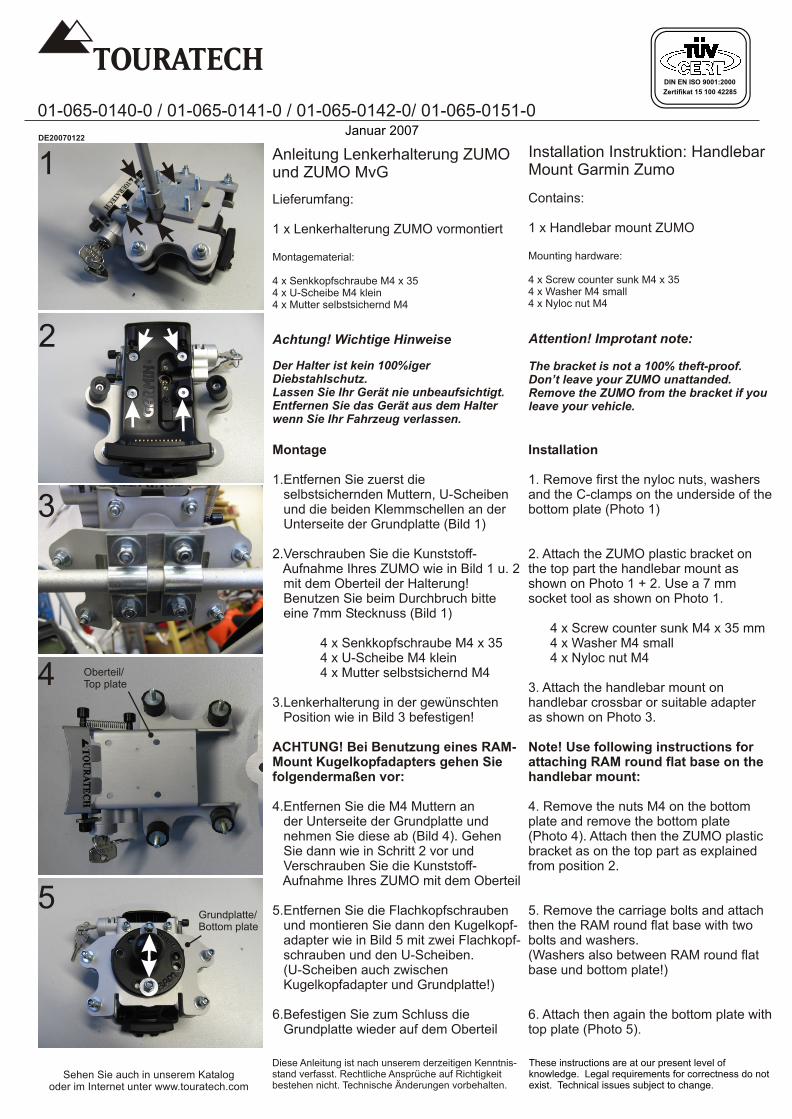
Montage
1.Entfernen Sie zuerst die selbstsichernden Muttern, U-Scheiben und die beiden Klemmschellen an der Unterseite der Grundplatte (Bild 1)
2.Verschrauben Sie die Kunststoff- Aufnahme Ihres ZUMO wie in Bild 1 u. 2 mit dem Oberteil der Halterung! Benutzen Sie beim Durchbruch bitte eine 7mm Stecknuss (Bild 1)
4 x Senkkopfschraube M4 x 354 x U-Scheibe M4 klein4 x Mutter selbstsichernd M4
3.Lenkerhalterung in der gewünschten Position wie in Bild 3 befestigen!
ACHTUNG! Bei Benutzung eines RAM-Mount Kugelkopfadapters gehen Sie folgendermaßen vor:
4.Entfernen Sie die M4 Muttern an der Unterseite der Grundplatte und nehmen Sie diese ab (Bild 4). Gehen Sie dann wie in Schritt 2 vor und Verschrauben Sie die Kunststoff- Aufnahme Ihres ZUMO mit dem Oberteil
5.Entfernen Sie die Flachkopfschrauben und montieren Sie dann den Kugelkopf- adapter wie in Bild 5 mit zwei Flachkopf- schrauben und den U-Scheiben. (U-Scheiben auch zwischen Kugelkopfadapter und Grundplatte!)
6.Befestigen Sie zum Schluss die Grundplatte wieder auf dem Oberteil
Achtung! Wichtige Hinweise
Der Halter ist kein 100%iger Diebstahlschutz.Lassen Sie Ihr Gerät nie unbeaufsichtigt.Entfernen Sie das Gerät aus dem Halter wenn Sie Ihr Fahrzeug verlassen.
Installation Instruktion: HandlebarMount Garmin Zumo
Lieferumfang:
1 x Lenkerhalterung ZUMO vormontiert
Montagematerial:
4 x Senkkopfschraube M4 x 354 x U-Scheibe M4 klein4 x Mutter selbstsichernd M4
01-065-0140-0 / 01-065-0141-0 / 01-065-0142-0/ 01-065-0151-0
Installation
1. Remove first the nyloc nuts, washers and the C-clamps on the underside of the bottom plate (Photo 1)
2. Attach the ZUMO plastic bracket on the top part the handlebar mount as shown on Photo 1 + 2. Use a 7 mm socket tool as shown on Photo 1.
4 x Screw counter sunk M4 x 35 mm4 x Washer M4 small4 x Nyloc nut M4
3. Attach the handlebar mount on handlebar crossbar or suitable adapter as shown on Photo 3.
Note! Use following instructions for attaching RAM round flat base on the handlebar mount:
4. Remove the nuts M4 on the bottom plate and remove the bottom plate (Photo 4). Attach then the ZUMO plastic bracket as on the top part as explained from position 2.
5. Remove the carriage bolts and attach then the RAM round flat base with two bolts and washers.(Washers also between RAM round flat base und bottom plate!)
6. Attach then again the bottom plate with top plate (Photo 5).
Attention! Improtant note:
The bracket is not a 100% theft-proof.Don’t leave your ZUMO unattanded.Remove the ZUMO from the bracket if you leave your vehicle.
Contains:
1 x Handlebar mount ZUMO
Mounting hardware:
4 x Screw counter sunk M4 x 354 x Washer M4 small4 x Nyloc nut M4
Anleitung Lenkerhalterung ZUMO und ZUMO MvG
These instructions are at our present level of knowledge. Legal requirements for correctness do not exist. Technical issues subject to change.
DE20070122
2
1
4
3
5Grundplatte/Bottom plate
Oberteil/Top plate
DIN EN ISO 9001:2000
Zertifikat 15 100 42285
01-065-0140-0 / 01-065-0141-0 / 01-065-0142-0
Diese Anleitung ist nach unserem derzeitigen Kenntnis-stand verfasst. Rechtliche Ansprüche auf Richtigkeit bestehen nicht. Technische Änderungen vorbehalten.
Sehen Sie auch in unserem Katalog oder im Internet unter www.touratech.com
These instructions are at our present level of knowledge. Legal requirements for correctness do not exist. Technical issues subject to change.
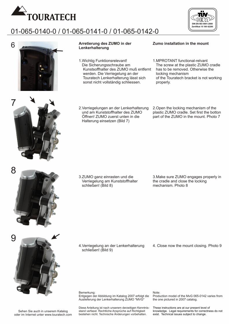
Arretierung des ZUMO in der Lenkerhalterung
1.Wichtig Funktionsrelevant! Die Sicherungsschraube am Kunstsoffhalter des ZUMO muß entfernt werden. Die Verriegelung an der Touratech Lenkerhalterung lässt sich sonst nicht vollständig schliessen.
2.Verriegelungen an der Lenkerhalterung und am Kunststoffhalter des ZUMO Öffnen! ZUMO zuerst unten in die Halterung einsetzen (Bild 7)
3.ZUMO ganz einrasten und die Verriegelung am Kunststoffhalter schließen! (Bild 8)
4.Verriegelung an der Lenkerhalterung schließen! (Bild 9)
Bemerkung:Entgegen der Abbildung im Katalog 2007 erfolgt die Auslieferung der Lenkerhalterung ZUMO *MVG*
6
7
8
Zumo installation in the mount
1.MPROTANT functional-relvant The screw at the plastic ZUMO cradle has to be removed. Otherwise the locking mechanism of the Touratech bracket is not working properly.
2.Open the locking mechanism of the plastic ZUMO cradle. Set first the botton part of the ZUMO in the mount. Photo 7
3.Make sure ZUMO engages properly in the cradle and close the locking mechanism. Photo 8
4. Close now the mount closing. Photo 9
Note:Production model of the MvG 065-0142 varies from the one pictured in 2007 catalog.
9