Embed Size (px)
Citation preview
W Ä R M E A U S TA U S C H E R
H E AT E X C H A N G E R S
É C H A N G E U R S D E C H A L E U R
Katalog Nr. 8801, Kapitel 6
Catalogue No. 8801, Section 6
Catalogue No 8801, Chapitre 6
B Ü C H I – T H E W A Y T O G E T R E S U L T S !®
176040_buechi_Kapitel_6_Waermetauscher_mit Pantone_176040_buechi_Kapitel_6_Waermeaustauscher 07.07.17 07:11 Seite 1
®
Seite
6.2 Einführung Wäremeaustauscher6.3 Spiralkühler aus Borosilicatglas6.6 Spiralkühler «büchiflex» 0,4–1,6 m2
6.8 Rückflusskondensator 1–1,3 m2
6.10 Kondensator/Kühler 1–1,3 m2
6.11 Produktkühler 0,1–1,0 m2
6.12 Rohrbündel-Wärmeaustauscher6.15 Rohrbündel-Wärmeaustauscher6.18 Rohrbündel-Wärmeaustauscher, Ausführung A,
ohne Sicherheitskammer6.19 Rohrbündel-Wärmeaustauscher, Ausführung B,
ohne Sicherheitskammer6.20 Rohrbündel-Wärmeaustauscher, Ausführung B,
mit Sicherheitskammer6.21 Wärmeaustauscher aus Metall6.23 Mehrfach-Heizkerze 0,1–10,0 m2
6.24 Einsatzheizer6.25 Spiralkondensator 0,4–1,3 m2
6.26 Emaillierter Kondensator6.27 Kühlfalle6.28 Mantelrohr DN 15–1506.29 Fragebogen
Hinweis:Alle grundlegenden Daten und Angaben zum Appa-rate- und Rohrleitungsbau mit Borosilicatglas 3.3 sindim Kapitel 2 des Kataloges Nr. 8801 enthalten.
Dort finden Sie detaillierte Aussagen über:• Werkstoffeigenschaften• Einsatzmöglichkeiten• «büchiglas»-Verbindungssysteme• Montage und Inbetriebnahme• Sicherheitsbestimmungen im Apparate- und Rohr-
leitungsbau mit Borosilicatglas 3.3.
Bitte geben Sie bei Ihrer Bestellung immer die vollständigeBestell-Nummer an, um Rückfragen und Lieferverzögerungenzu vermeiden!
Inhaltsverzeichnis
176040_buechi_Kapitel_6_Waermetauscher_mit Pantone_176040_buechi_Kapitel_6_Waermeaustauscher 07.07.17 07:11 Seite 2
6.1®
Page
6.2 Introduction to heat exchangers6.3 Spiral coolers made of borosilicate glass6.6 Spiral cooler «büchiflex» 0.4–1.6 m2
6.8 Reflux condenser 1–1.3 m2
6.10 Condenser/Cooler 1–1.3 m2
6.11 Product cooler 0.1–1.0 m2
6.12 Shell-and-tube heat exchanger6.15 Shell-and-tube heat exchanger6.18 Shell-and-tube heat exchanger, type A6.19 Shell-and-tube heat exchanger, type B,
without safety chamber6.20 Shell-and-tube heat exchanger, type B,
with safety chamber6.21 Metal heat exchangers6.23 Multiple heating cartridge 0.1–10.0 m2
6.24 Immersion heat exchanger6.25 Spiralcondenser 0.4–1.3 m2
6.26 Glass lined steel condensator6.27 Cooling trap6.28 Jacketed tube DN 15–1506.29 Questionnaire
Page
6.2 Introduction sur les échangeurs de chaleur6.3 Réfrigérants spiralés en verre au borosilicat6.6 Réfrigérant spiralé «büchiflex» 0,4–1,6 m2
6.8 Condenseur à reflux 1–1,3 m2
6.10 Condenseur/Réfrigérant 1–1,3 m2
6.11 Réfrigérant de produit 0,1–1,0 m2
6.12 Echangeurs de chaleur à faisceau tubulaire6.15 Echangeurs de chaleur à faisceau tubulaire6.18 Echangeurs de chaleur à faisceau tubulaire,
exécution A, sans chambre de sécurité6.19 Echangeurs de chaleur à faisceau tubulaire,
exécution B, sans chambre de sécurité6.20 Echangeurs de chaleur à faisceau tubulaire,
exécution B, avec chambre de sécurité6.21 Echangeurs de chaleur en métal6.23 Bougie chauffante multiple 0,1–10,0 m2
6.24 Organes de chauffage6.25 Réfrigérant spiralé 0,4–1,3 m2
6.26 Condenseur émaillée6.27 Piège cryogénique6.28 Tube à double enveloppe DN 15–1506.29 Questionnaire
Note:All basic data and information relating to borosilicateglass 3.3 apparatus and piping constructions are con-tained in section 2 of cataloge No. 8801.
There you will find detailed information concerning:• Properties of materials• Applications• «büchiglas» connecting systems• Assembly and start-up• Safety regulations pertaining to the construction
of apparatus and piping systems with borosilicateglass 3.3
Please state the complete order number when ordering to avoidunnecessary queries and delivery delays!
Remarque:Toutes les données et indications fondamentales pourla construction d’appareils et de tuyauteries en verre auborosilicate 3.3 sont mentionnées dans le chapitre 2du catalogue no 8801.
Vous y trouverez des indications détaillées sur:• les caractéristiques des matières• les possibilités d’utilisation• les systèmes de raccordement «büchiglas»• le montage et la mise en service• les dispositions de sécurité dans la construction d’ap-
pareils et de tuyauteries en verre au borosilicate 3.3
Veuillez toujours indiquer le numéro de référence complet dans votrecommande de manière à éviter des questions et retards de livraison!
Table of contents Table des matières
176040_buechi_Kapitel_6_Waermetauscher_mit Pantone_176040_buechi_Kapitel_6_Waermeaustauscher 07.07.17 07:11 Seite 1
6.2 ®
Wärmeaustauscher aus hochkorrosions-beständigen Werkstoffen sind im Chemie-anlagenbau von überragender Bedeu-tung. Bei zahlreichen Verfahren in derchemischen Verfahrenstechnik muss Wär-me zu- oder abgeführt werden.
«büchiglasuster» bietet dem Anwenderein breitgefächertes Lieferprogramm vonWärmeaustauschern an. Dies stellt eineoptimale Lösung von unterschiedlichstenAufgabenstellungen sicher. Die in derPraxis bewärten Konstruktionen zeichnensich durch universelle Korrosionsbestän-digkeit und hohe Austauschleistung aus.Die verwendeten Werkstoffe wie Borosili-catglas 3.3, Tantal, Titan, Hastelloy, Sili-ziumcarbid (Keramik) Edelstähle, PTFE,KALREZ®* usw. erlauben eine hohe Be-triebssicherheit bei Arbeiten mit aggres-sivsten Medien.
Heat exchangers made of highly corro-sion-résistant materials are of paramountimportance in the construction of chemi-cal installations. Heat must be supplied orremoved in many of the processes in che-mical process technologies.
«büchiglasuster» offers the user a widerange of heat exchangers. These ensureoptimum solutions to greatly differingproblems. The tested and proven designsare characterized by virtually unlimitedcorrosion resistance and by high heat ex-change efficiency. The materials usedsuch as borosilicate glass 3.3, tantalum,titanium, hastelloy, Silicon Carbide (ce-ramic), stainless steels, PTFE, KALREZ®*,etc., provide a high level of operatingsafety when aggressive media are beingprocessed.
Des échangeurs de chaleur en matièreshautement résistantes à la corrosion sontd’une importance déterminante dans laconstruction d’installations chimiques. Dela chaleur doit être apportée ou enlevéedans de nombreux procédés de géniechimique.
«büchiglasuster» offre à l’utilisateur unprogramme de livraison très diversifiéd’échangeurs de chaleur. Ceci garantitde trouver une solution optimale aux pro-blèmes les plus divers posés. Les construc-tions éprouvées dans la pratique se distin-guent par une résistance universelle à lacorrosion et une puissance d’échangeélevée. Les matières utilisées telles queverre au borosilicate 3.3, tantale, titanehastelloy, carbure de silicium (ceramic),aciers inoxydables, PTFE, KALREZ®* etc.assurent une haute sécurité d’exploitationdans l’utilisation des fluides les plusagressifs.
Einführung Wärmeaustauscher
Introduction to heat exchangers
Introduction sur les échangeurs
Deutsch English Français
176040_buechi_Kapitel_6_Waermetauscher_mit Pantone_176040_buechi_Kapitel_6_Waermeaustauscher 07.07.17 07:11 Seite 2
6.3®
Die Wärmeaustauscher sind vollständigaus Borosilikatglas 3.3 gefertigt. DieAustauscherspiralen sind mit dem Mantelverschmolzen. Daraus resultieren folgen-de Hauptvorteile:• Keine Dichtstellen zwischen Mantel-
und Rohrseite.• Hervorragende Korrosionsbeständig-
keit durch ausschliessliche Verwen-dung von Borosilicatglas.
• Herstellung reinster Produkte durchglatte und porenfreie Oberfläche.
• Keine Angabe von Schwermetallen.
«büchiglasuster» liefert diesen Austau-schertyp in verschiedenen Bauformen undAustauschflächen von 0,15–1,6 m2.Grössere Austauschflächen lassen sichdurch Kombinationen mehrerer Spiralküh-ler realisieren (siehe 6.5).
Der zulässige Betriebsüberdruck in denSpiralen beträgt bei allen Austauscher-typen 3 bar. Dabei sind nachstehendeHinweise für den Einsatz von Spiralküh-lern und das Anschlussschema zu beach-ten (siehe 6.5).
Der zulässige Betriebsüberdruck im Man-tel entspricht den Angaben, die im einfüh-renden Katalogkapitel 2 «Technische In-formationen» in Abhängigkeit der Nenn-werte und der Temperaturdifferenz ∆Tausgeführt sind.
These heat exchanges are made entirelyof borosilicate glass 3.3. The exchangespiral and jacket are fused together. Thisresults in the following main advantages:• No jacket/tube joints requiring seals• Outstanding corrosion resistance due
to the use of borosilicate glass only• Smooth, pore-free surface permits the
manufacture of the purest products• No release of heavy metals
«büchiglasuster» supplies this type ofheat exchanger in various configura-tions and with heat transfer areas from0.15–1.6 m2.
Larger surface can be obtained by com-bining several spiral coolers (see 6.5).
The permissible operating pressure in thespirals is 3 bar (gauge) for all heatexchanger types. However, the instruc-tions given below for the use of spiralcoolers and the connecting diagram mustbe observed (see 6.5).
The permissible operating pressure(gauge) in the jacket depends on thenominal internal diameter and the tem-perature difference ∆T according to theinformation given in catalogue section 2«Technical information».
Ces échangeurs de chaleur sont entière-ment fabriqués en verre au borosilicate3.3. Les spirales des échangeurs sont fon-dues avec l’enveloppe. Il en résulte lesprincipaux avantages suivants:• pas de joint d’étanchéité nécessaire
entre l’enveloppe et le tube.• résistance exceptionnelle à la corro-
sion par l’utilisation exclusive de verreau borosilicate
• fabrication de produits de la plushaute pureté par une surface lisse etsans pore
• pas de dépôt de métaux lourds.
«büchiglasuster» fournit ce type d’échan-geur dans différentes formes de construc-tion et avec des surfaces d’échange de0,15–1,6 m2.
Des surfaces d’échange plus importantespeuvent être obtenues par la combinai-son de plusieurs réfrigérants spiralés (voir6.5).
La surpression de service admissible dansles spirales s’élève pour tous les typesd’échangeurs à 3 bars. A ce sujet, le sché-ma de raccordement et les instructions ci-dessous doivent être observés pour l’utili-sation des réfrigérants spiralés (6.5). Lasurpression de service admissible dansl’enveloppe correspond aux indicationsqui sont mentionnées dans le chapitred’introduction du catalogue 2 «informa-tions techniques» en fonction du diamètrenominal et de la différence de tempéra-ture ∆T.
Spiralkühler aus Borosilikatglas
Spiral coolers made of borosilicate glass
Réfrigérants spiralés en verre au borosilicate
Deutsch English Français
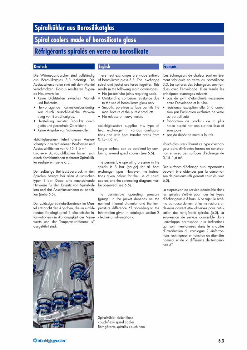
Spiralkühler «büchiflex»«büchiflex» spiral coolerRéfrigérants spiralés «büchiflex»
176040_buechi_Kapitel_6_Waermetauscher_mit Pantone_176040_buechi_Kapitel_6_Waermeaustauscher 07.07.17 07:11 Seite 3
6.4 ®
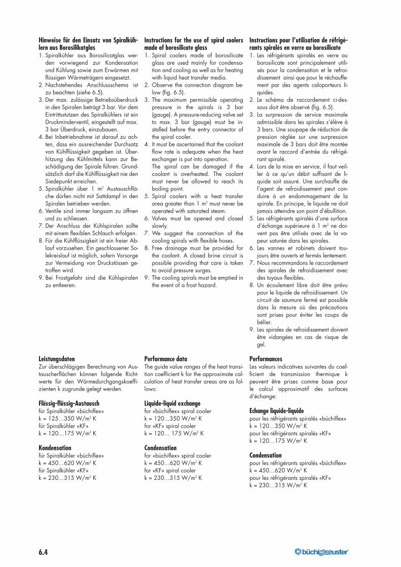
Hinweise für den Einsatz von Spiralküh-lern aus Borosilikatglas1. Spiralkühler aus Borosilicatglas wer-
den vorwiegend zur Kondensationund Kühlung sowie zum Erwärmen mitflüssigen Wärmeträgern eingesetzt.
2. Nachstehendes Anschlussschema istzu beachten (siehe 6.5).
3. Der max. zulässige Betriebsüberdruckin den Spiralen beträgt 3 bar. Vor demEintrittsstutzen des Spiralkühlers ist einDruckminderventil, eingestellt auf max.3 bar Überdruck, einzubauen.
4. Bei Inbetriebnahme ist darauf zu ach-ten, dass ein ausreichender Durchsatzvon Kühlflüssigkeit gegeben ist. Über-hitzung des Kühlmittels kann zur Be-schädigung der Spirale führen. Grund-sätzlich darf die Kühlflüssigkeit nie denSiedepunkt erreichen.
5. Spiralkühler über 1 m2 Austauschflä-che dürfen nicht mit Sattdampf in denSpiralen betrieben werden.
6. Ventile sind immer langsam zu öffnenund zu schliessen.
7. Der Anschluss der Kühlspiralen solltemit einem flexiblen Schlauch erfolgen.
8. Für die Kühlflüssigkeit ist ein freier Ab-lauf vorzusehen. Ein geschlossener So-lekreislauf ist möglich, sofern Vorsorgezur Vermeidung von Druckstössen ge-troffen wird.
9. Bei Frostgefahr sind die Kühlspiralenzu entleeren.
LeistungsdatenZur überschlägigen Berechnung von Aus-tauscherflächen können folgende Richt-werte für den Wärmedurchgangskoeffi-zienten k zugrunde gelegt werden.
Flüssig-flüssig-Austauschfür Spiralkühler «büchiflex»k = 125…350 W/m2 Kfür Spiralkühler «KF»k = 120…175 W/m2 K
Kondensationfür Spiralkühler «büchiflex»k = 450…620 W/m2 Kfür Spiralkühler «KF»k = 230…315 W/m2 K
Instructions for the use of spiral coolersmade of borosilicate glass1. Spiral coolers made of borosilicate
glass are used mainly for condensa-tion and cooling as well as for heatingwith liquid heat transfer media.
2. Observe the connection diagram be-low (fig. 6.5).
3. The maximum permissible operatingpressure in the spirals is 3 bar(gauge). A pressure-reducing valve setto max. 3 bar (gauge) must be in-stalled before the entry connector ofthe spiral cooler.
4. It must be ascertained that the coolantflow rate is adequate when the heatexchanger is put into operation.The spiral can be damaged if thecoolant is overheated. The coolantmust never be allowed to reach itsboiling point.
5. Spiral coolers with a heat transferarea greater than 1 m2 must never beoperated with saturated steam.
6. Valves must be opened and closedslowly.
7. We suggest the connection of thecooling spirals with flexible hoses.
8. Free drainage must be provided forthe coolant. A closed brine circuit ispossible providing that care is takento avoid pressure surges.
9. The cooling spirals must be emptied inthe event of a frost hazard.
Performance dataThe guide value ranges of the heat transi-tion coefficient k for the approximate cal-culation of heat transfer areas are as fol-lows:
Liquide-liquid exchangefor «büchiflex» spiral coolerk = 120…350 W/m2 Kfor «KF» spiral coolerk = 120… 175 W/m2 K
Condensationfor «büchiflex» spiral coolerk = 450…620 W/m2 Kfor «KF» spiral coolerk = 230…315 W/m2 K
Instructions pour l’utilisation de réfrigé-rants spiralés en verre au borosilicate1. Les réfrigérants spiralés en verre au
borosilicate sont principalement utili-sés pour la condensation et le refroi-dissement ainsi que pour le réchauffe-ment par des agents caloporteurs li-quides.
2. Le schéma de raccordement ci-des-sous doit être observé (fig. 6.5).
3. La surpression de service maximaleadmissible dans les spirales s’élève à3 bars. Une soupape de réduction depression réglée sur une surpressionmaximale de 3 bars doit être montéeavant le raccord d’entrée du réfrigé-rant spiralé.
4. Lors de la mise en service, il faut veil-ler à ce qu’un débit suffisant de li-quide soit assuré. Une surchauffe del’agent de refroidissement peut con-duire à un endommagement de laspirale. En principe, le liquide ne doitjamais atteindre son point d’ébullition.
5. Les réfrigérants spiralés d’une surfaced’échange supérieure à 1 m2 ne doi-vent pas être utilisés avec de la va-peur saturée dans les spirales.
6. Les vannes et robinets doivent tou-jours être ouverts et fermés lentement.
7. Nous recommandons le raccordementdes spirales de refroidissement avecdes tuyaux flexibles.
8. Un écoulement libre doit être prévupour le liquide de refroidissement. Uncircuit de saumure fermé est possibledans la mesure où des précautionssont prises pour éviter les coups debélier.
9. Les spirales de refroidissement doiventêtre vidangées en cas de risque degel.
PerformancesLes valeurs indicatives suivantes du coef-ficient de transmission thermique kpeuvent être prises comme base pourle calcul approximatif des surfacesd’échange:
Echange liquide-liquidepour les réfrigérants spiralés «büchiflex»k = 120…350 W/m2 Kpour les réfrigérants spiralés «KF»k = 120…175 W/m2 K
Condensationpour les réfrigérants spiralés «büchiflex»k = 450…620 W/m2 Kpour les réfrigérants spiralés «KF»k = 230…315 W/m2 K
176040_buechi_Kapitel_6_Waermetauscher_mit Pantone_176040_buechi_Kapitel_6_Waermeaustauscher 07.07.17 07:11 Seite 4
6.5®
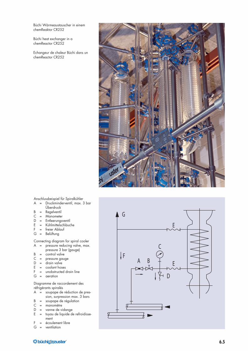
Anschlussbeispiel für SpiralkühlerA = Druckminderventil, max. 3 bar
ÜberdruckB = RegelventilC = ManometerD = EntleerungsventilE = KühlmittelschläucheF = freier AblaufG = Belüftung
Connecting diagram for spiral coolerA = pressure reducing valve, max.
pressure 3 bar (gauge)B = control valveC = pressure gaugeD = drain valveE = coolant hosesF = unobstructed drain lineG = aeration
Diagramme de raccordement desréfrigérants spiralésA = soupape de réduction de pres-
sion, surpression max. 3 barsB = soupape de régulationC = manomètreD = vanne de vidangeE = tuyau de liquide de refroidisse-
mentF = écoulement libreG = ventilation
E
EA B
C
D
G
F
Büchi Wärmeaustauscher in einemchemReaktor CR252
Büchi heat exchanger in achemReactor CR252
Echangeur de chaleur Büchi dans unchemReactor CR252
176040_buechi_Kapitel_6_Waermetauscher_mit Pantone_176040_buechi_Kapitel_6_Waermeaustauscher 07.07.17 07:11 Seite 5
6.6 ®
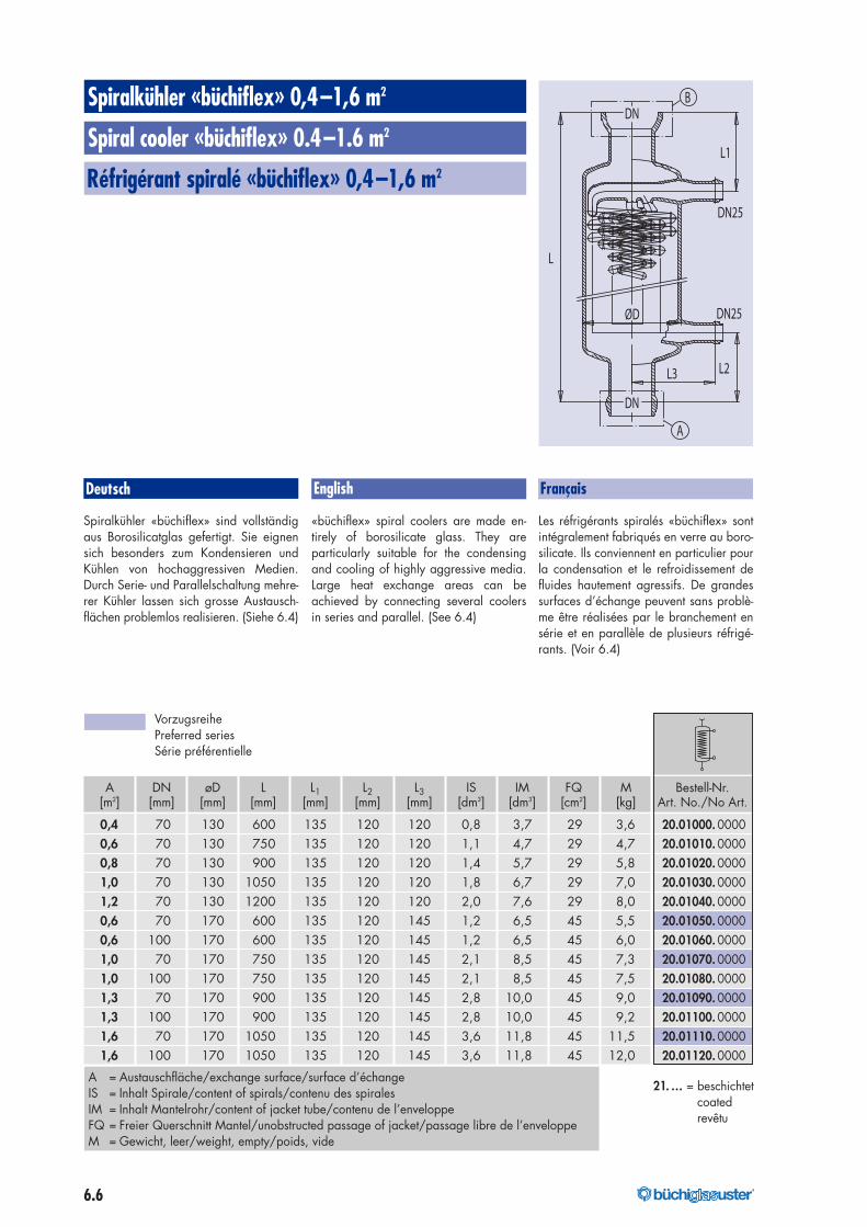
A DN øD L L1 L2 L3 IS IM FQ M Bestell-Nr.[m2] [mm] [mm] [mm] [mm] [mm] [mm] [dm3] [dm3] [cm2] [kg] Art. No./No Art.
0,4 70 130 600 135 120 120 0,8 3,7 29 3,6 20.01000. 00000,6 70 130 750 135 120 120 1,1 4,7 29 4,7 20.01010. 00000,8 70 130 900 135 120 120 1,4 5,7 29 5,8 20.01020. 00001,0 70 130 1050 135 120 120 1,8 6,7 29 7,0 20.01030. 00001,2 70 130 1200 135 120 120 2,0 7,6 29 8,0 20.01040. 00000,6 70 170 600 135 120 145 1,2 6,5 45 5,5 20.01050. 00000,6 100 170 600 135 120 145 1,2 6,5 45 6,0 20.01060. 00001,0 70 170 750 135 120 145 2,1 8,5 45 7,3 20.01070. 00001,0 100 170 750 135 120 145 2,1 8,5 45 7,5 20.01080. 00001,3 70 170 900 135 120 145 2,8 10,0 45 9,0 20.01090. 00001,3 100 170 900 135 120 145 2,8 10,0 45 9,2 20.01100. 00001,6 70 170 1050 135 120 145 3,6 11,8 45 11,5 20.01110. 00001,6 100 170 1050 135 120 145 3,6 11,8 45 12,0 20.01120. 0000
Spiralkühler «büchiflex» sind vollständigaus Borosilicatglas gefertigt. Sie eignensich besonders zum Kondensieren undKühlen von hochaggressiven Medien.Durch Serie- und Parallelschaltung mehre-rer Kühler lassen sich grosse Austausch-flächen problemlos realisieren. (Siehe 6.4)
«büchiflex» spiral coolers are made en-tirely of borosilicate glass. They areparticularly suitable for the condensingand cooling of highly aggressive media.Large heat exchange areas can beachieved by connecting several coolersin series and parallel. (See 6.4)
Les réfrigérants spiralés «büchiflex» sontintégralement fabriqués en verre au boro-silicate. Ils conviennent en particulier pourla condensation et le refroidissement defluides hautement agressifs. De grandessurfaces d’échange peuvent sans problè-me être réalisées par le branchement ensérie et en parallèle de plusieurs réfrigé-rants. (Voir 6.4)
A = Austauschfläche/exchange surface/surface d’échangeIS = Inhalt Spirale/content of spirals/contenu des spiralesIM = Inhalt Mantelrohr/content of jacket tube/contenu de l’enveloppeFQ = Freier Querschnitt Mantel/unobstructed passage of jacket/passage libre de l’enveloppeM = Gewicht, leer/weight, empty/poids, vide
DN
DN
DN25
DN25
B
A
L1
L2L3
L
ØD
VorzugsreihePreferred seriesSérie préférentielle
21. … = beschichtetcoatedrevêtu
Spiralkühler «büchiflex» 0,4–1,6 m2
Spiral cooler «büchiflex» 0.4–1.6 m2
Réfrigérant spiralé «büchiflex» 0,4–1,6 m2
Deutsch English Français
176040_buechi_Kapitel_6_Waermetauscher_mit Pantone_176040_buechi_Kapitel_6_Waermeaustauscher 07.07.17 07:11 Seite 6
6.7®
0.5 1.0 1.5 5.0
110
100
90
80
70
60
50
40
30
20
10
2.0 2.5 3.0 3.5 4.0 4.5
120
1301.6 m2
1.3 m2
1.0 m21.2 m2
1.0 m20.6 m20.8 m20.6 m2
0.4 m2
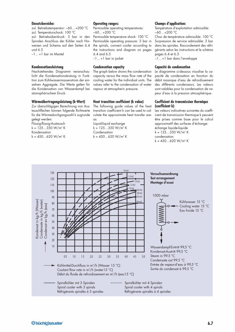
Kühlmittel-Durchfluss in m3/h (Wasser 15 °C)Coolant flow rate in m3/h (water15 °C)Débit du fluide de refroidissement en m3/h (eau15 °C)
Spiralkühler mit 3 Spiralen Spiralkühler mit 4 SpiralenSpiral cooler with 3 spirals Spiral cooler with 4 spiralsRéfrigérants spiralés à 3 spirales Réfrigérants spiralés à 4 spirales
Kond
ensa
tin
kg/h
(Was
ser)
Con
dens
ate
inkg
/h(w
ater
)C
onde
nsat
enkg
/h(e
au)
VersuchsanordnungTest arrangementMontage d’essai
1000 mbar
Kühlwasser 15 °CCooling water 15 °CEau froide 15 °C
Wasserdampf-Eintritt 99,5 °CKondensat-Austritt 99,5 °CSteam in 99.5 °CCondensate out 99.5 °CEntrée de vapeur-d’eau à 99,5 °CSortie du condensat à 99,5 °C
Einsatzbereiche:zul. Betriebstemperatur: –60…+200 °Czul. Temperaturschock: 100 °Czul. Betriebsüberdruck: 3 bar in denSpiralen Anschluss der Kühler nach Hin-weisen und Schema auf den Seiten 6.4und 6.5–1…+1 bar im Mantel
KondensationsleistungNachstehendes Diagramm veranschau-licht die Kondensationsleistung in Funk-tion zum Kühlwassermassenstrom der ein-zelnen Aggregate. Die Werte gelten fürdie Kondensation von Wasserdampf beiatomsphärischem Druck.
Wärmeübertragungsleistung (k-Wert)Zur überschlägigen Berechnung von Aus-tauschflächen können folgende Richtwertefür die Wärmedurchgangszahl k zugrundegelegt werden:Flüssig-flüssig-Austauschk = 125…350 W/m2 KKondensationk = 450…620 W/m2 K
Operating ranges:Permissible operating temperatures:–60…+200 °CPermissible temperature shock: 100 °CPermissible operating pressure: 3 bar inthe spirals, connect cooler according tothe instructions and diagram on pages6.4 and 6.5–1…+1 bar in jacket
Condensation capacityThe graph below shows the condensationcapacity versus the mass flow rate of thecooling water for the individual units. Thevalues refer to the condensation of watervapour at atmospheric pressure.
Heat transition coefficient (k value)The following guide values of the heattransition coefficient k can be used to cal-culate the approximate heat transfer are-as:Liquid-liquid exchangek = 125…350 W/m2 KCondensationk = 450…620 W/m2 K
Champs d’application:Température d’exploitation admissible:–60…+200 °CChoc de température admissible: 100 °CSurpression de service admissible: 3 bardans les spirales. Raccordement des réfri-gérants selon les instructions et le schémapages 6.4 et 6.5–1…+1 bar dans l’enveloppe
Capacité de condensationLe diagramme ci-dessous visualise la ca-pacité de condensation en fonction dudébit massique d’eau de refroidissementdes différents condenseurs. Les valeurssont valables pour la condensation de va-peur d’eau à la pression atmosphérique.
Coefficient de transmission thermique(coefficient k)Les valeurs indicatives suivantes du coeffi-cient de transmission thermique k peuventêtre prises comme base pour le calculapproximatif des surfaces d’échange:échange liquide-liquidek = 125…350 W/m2 Kcondensationk = 450…620 W/m2 K
176040_buechi_Kapitel_6_Waermetauscher_mit Pantone_176040_buechi_Kapitel_6_Waermeaustauscher 07.07.17 07:11 Seite 7
6.8 ®
Rückflusskondensator 1–1,3 m2
Reflux condenser 1–1.3 m2
Condenseur à reflux 1–1,3 m2
Deutsch FrançaisEnglish
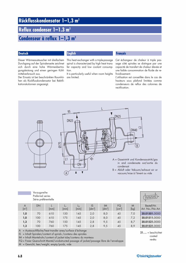
Dieser Wärmeaustauscher mit dreifachemDurchgang auf der Spiralenseite zeichnetsich durch eine hohe Wärmeübertra-gungsleistung und einen geringen Kühl-mittelverbrauch aus.Der Einsatz ist bei beschränkten Raumhö-hen als Rückflusskondensator bei Rektifi-kationskolonnen angezeigt.
This heat exchanger with a triple-passagespiral is characterized by high heat trans-fer capacity and low coolant consump-tion.It is particularly useful when room heightsare limited.
Cet échangeur de chaleur à triple pas-sage côté spirales se distingue par unecapacité de transfert de chaleur élevée etune faible consommation de fluide de re-froidissement.L’utilisation est conseillée dans le cas dehauteurs sous plafond limitées commecondenseurs de reflux des colonnes derectification.
DN25DN25
A
DN40
DN
B
95o
L
L1
95
Ø170
L2
A DN L L1 L2 IS IM FQ M Bestell-Nr.[m2] [mm] [mm] [mm] [dm3] [dm3] [cm2] [kg] Art. No./No Art.
1,0 70 610 150 145 2,0 8,0 45 7,0 20.01501.00001,0 100 610 175 145 2,0 8,0 45 7,2 20.01511.00001,3 70 760 150 145 2,8 9,5 45 8,7 20.01521.00001,3 100 760 175 145 2,8 9,5 45 8,9 20.01531.0000
A = Austauschfläche/heat transfer area/surface d’échangeIS = Inhalt Spiralen/content of spirals /contenu des spiralesIM = Inhalt Mantelrohr/content of jacket tube/contenu du manteauFQ = Freier Querschnitt Mantel/unobstructed passage of jacket/passage libre de l’enveloppeM = Gewicht, leer/weight, empty/poids, vide
A = Gaseintritt und Kondensaustritt/gasin and condensate out/sortie ducondensat
B = Abluft oder Vakuum/exhaust air orvacuum/mise à l’évent ou vide
VorzugsreihePreferred seriesSérie préférentielle
21. … = beschichtetcoatedrevêtu
176040_buechi_Kapitel_6_Waermetauscher_mit Pantone_176040_buechi_Kapitel_6_Waermeaustauscher 07.07.17 07:11 Seite 8
6.9®
0.5 1.0 1.5 2.0
110
100
90
80
70
60
50
40
30
20
10
Kühlmittel-Durchflussin m3/h (Wasser 15 °C)Coolant flow ratein m3/h (water15 °C)Débit du fluide derefroidissement en m3/h(eau15 °C)
Kond
ensa
tin
kg/h
(Was
ser)
Con
dens
ate
inkg
/h(w
ater
)C
onde
nsat
enkg
/h(e
au)
KondensationsleistungCondensation capacityCapacité de condensation
VersuchsanordnungTest arrangementArrangement d’essai
Kühlwasser 15 °CCooling water 15 °CEau froide 15 °C
1000 mbar
Wasserdampf-Eintritt 99,5 °CKondensat-Austritt 99,5 °CSteam in 99.5 °CCondensate out 99.5 °CEntrée de vapeur-d’eau à 99,5 °CSortie du condensat à 99,5 °C
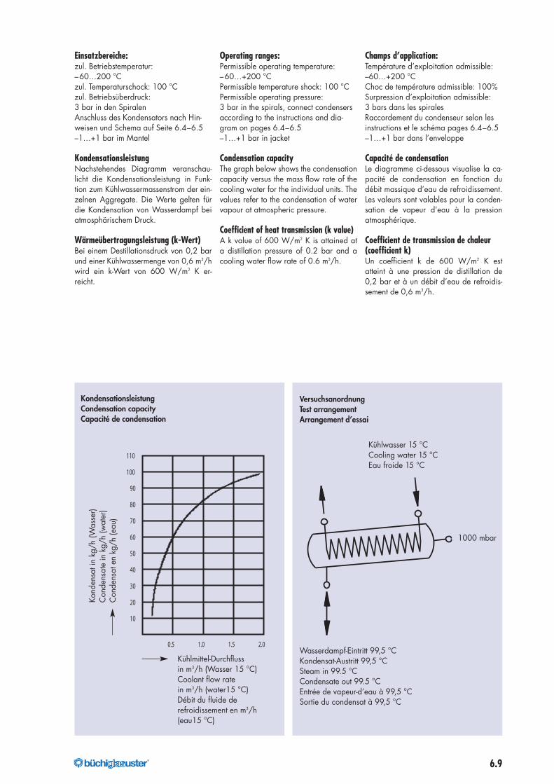
Einsatzbereiche:zul. Betriebstemperatur:–60…200 °Czul. Temperaturschock: 100 °Czul. Betriebsüberdruck:3 bar in den SpiralenAnschluss des Kondensators nach Hin-weisen und Schema auf Seite 6.4–6.5–1…+1 bar im Mantel
KondensationsleistungNachstehendes Diagramm veranschau-licht die Kondensationsleistung in Funk-tion zum Kühlwassermassenstrom der ein-zelnen Aggregate. Die Werte gelten fürdie Kondensation von Wasserdampf beiatmosphärischem Druck.
Wärmeübertragungsleistung (k-Wert)Bei einem Destillationsdruck von 0,2 barund einer Kühlwassermenge von 0,6 m3/hwird ein k-Wert von 600 W/m2 K er-reicht.
Operating ranges:Permissible operating temperature:–60…+200 °CPermissible temperature shock: 100 °CPermissible operating pressure:3 bar in the spirals, connect condensersaccording to the instructions and dia-gram on pages 6.4–6.5–1…+1 bar in jacket
Condensation capacityThe graph below shows the condensationcapacity versus the mass flow rate of thecooling water for the individual units. Thevalues refer to the condensation of watervapour at atmospheric pressure.
Coefficient of heat transmission (k value)A k value of 600 W/m2 K is attained ata distillation pressure of 0.2 bar and acooling water flow rate of 0.6 m3/h.
Champs d’application:Température d’exploitation admissible:–60…+200 °CChoc de température admissible: 100%Surpression d’exploitation admissible:3 bars dans les spiralesRaccordement du condenseur selon lesinstructions et le schéma pages 6.4–6.5–1…+1 bar dans l’enveloppe
Capacité de condensationLe diagramme ci-dessous visualise la ca-pacité de condensation en fonction dudébit massique d’eau de refroidissement.Les valeurs sont valables pour la conden-sation de vapeur d’eau à la pressionatmosphérique.
Coefficient de transmission de chaleur(coefficient k)Un coefficient k de 600 W/m2 K estatteint à une pression de distillation de0,2 bar et à un débit d’eau de refroidis-sement de 0,6 m3/h.
176040_buechi_Kapitel_6_Waermetauscher_mit Pantone_176040_buechi_Kapitel_6_Waermeaustauscher 07.07.17 07:11 Seite 9
6.10 ®
Kondensator/Kühler 1–1,3 m2
Condenser/Cooler 1–1.3 m2
Condenseur/Réfrigérant 1–1,3 m2
Deutsch FrançaisEnglish
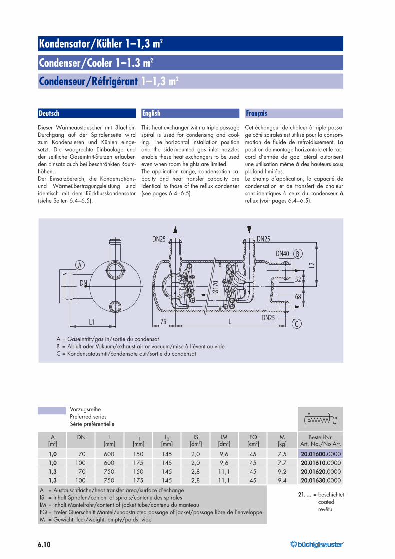
Dieser Wärmeaustauscher mit 3fachemDurchgang auf der Spiralenseite wirdzum Kondensieren und Kühlen einge-setzt. Die waagrechte Einbaulage undder seitliche Gaseintritt-Stutzen erlaubenden Einsatz auch bei beschränkten Raum-höhen.Der Einsatzbereich, die Kondensations-und Wärmeübertragungsleistung sindidentisch mit dem Rückflusskondensator(siehe Seiten 6.4–6.5).
This heat exchanger with a triple-passagespiral is used for condensing and cool-ing. The horizontal installation positionand the side-mounted gas inlet nozzlesenable these heat exchangers to be usedeven when room heights are limited.The application range, condensation ca-pacity and heat transfer capacity areidentical to those of the reflux condenser(see pages 6.4–6.5).
Cet échangeur de chaleur à triple passa-ge côté spirales est utilisé pour la consom-mation de fluide de refroidissement. Laposition de montage horizontale et le rac-cord d’entrée de gaz latéral autorisentune utilisation même à des hauteurs sousplafond limitées.Le champ d’application, la capacité decondensation et de transfert de chaleursont identiques à ceux du condenseur àreflux (voir pages 6.4–6.5).
1.0 m 2
DN25 DN25
DN40
DN25C
A
B
DN
L2
LL1 75
68
Ø170
52
A DN L L1 L2 IS IM FQ M Bestell-Nr.[m2] [mm] [mm] [mm] [dm3] [dm3] [cm2] [kg] Art. No./No Art.
1,0 70 600 150 145 2,0 9,6 45 7,5 20.01600.00001,0 100 600 175 145 2,0 9,6 45 7,7 20.01610.00001,3 70 750 150 145 2,8 11,1 45 9,2 20.01620.00001,3 100 750 175 145 2,8 11,1 45 9,4 20.01630.0000
A = Austauschfläche/heat transfer area/surface d’échangeIS = Inhalt Spiralen/content of spirals/contenu des spiralesIM = Inhalt Mantelrohr/content of jacket tube/contenu du manteauFQ = Freier Querschnitt Mantel/unobstructed passage of jacket/passage libre de l’enveloppeM = Gewicht, leer/weight, empty/poids, vide
A = Gaseintritt/gas in/sortie du condensatB = Abluft oder Vakuum/exhaust air or vacuum/mise à l’évent ou videC = Kondensataustritt/condensate out/sortie du condensat
VorzugsreihePreferred seriesSérie préférentielle
21. … = beschichtetcoatedrevêtu
176040_buechi_Kapitel_6_Waermetauscher_mit Pantone_176040_buechi_Kapitel_6_Waermeaustauscher 07.07.17 07:11 Seite 10
6.11®
Produktkühler 0,1–1,0 m2
Product cooler 0.1–1.0 m2
Réfrigérant de produit 0,1–1,0 m2
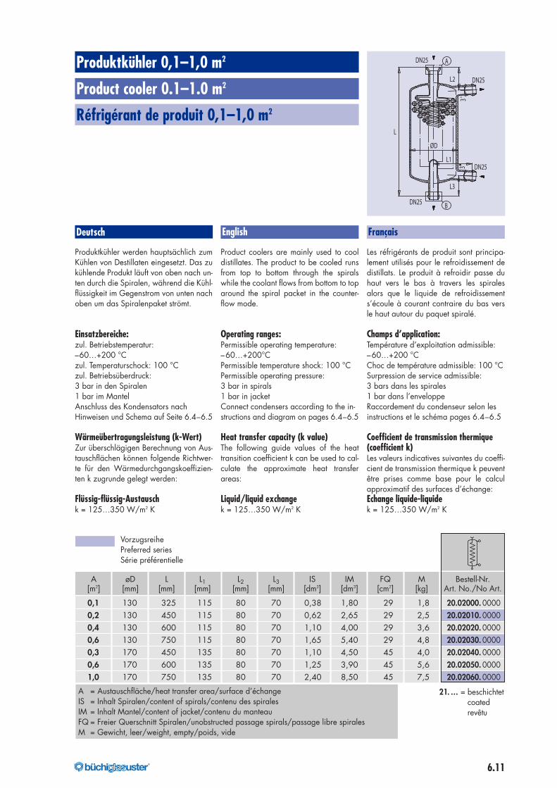
A øD L L1 L2 L3 IS IM FQ M Bestell-Nr.[m2] [mm] [mm] [mm] [mm] [mm] [dm3] [dm3] [cm2] [kg] Art. No./No Art.
0,1 130 325 115 80 70 0,38 1,80 29 1,8 20.02000. 00000,2 130 450 115 80 70 0,62 2,65 29 2,5 20.02010. 00000,4 130 600 115 80 70 1,10 4,00 29 3,6 20.02020. 00000,6 130 750 115 80 70 1,65 5,40 29 4,8 20.02030. 00000,3 170 450 135 80 70 1,10 4,50 45 4,0 20.02040. 00000,6 170 600 135 80 70 1,25 3,90 45 5,6 20.02050. 00001,0 170 750 135 80 70 2,40 8,50 45 7,5 20.02060. 0000
Deutsch FrançaisEnglish
Produktkühler werden hauptsächlich zumKühlen von Destillaten eingesetzt. Das zukühlende Produkt läuft von oben nach un-ten durch die Spiralen, während die Kühl-flüssigkeit im Gegenstrom von unten nachoben um das Spiralenpaket strömt.
Einsatzbereiche:zul. Betriebstemperatur:–60…+200 °Czul. Temperaturschock: 100 °Czul. Betriebsüberdruck:3 bar in den Spiralen1 bar im MantelAnschluss des Kondensators nachHinweisen und Schema auf Seite 6.4–6.5
Wärmeübertragungsleistung (k-Wert)Zur überschlägigen Berechnung von Aus-tauschflächen können folgende Richtwer-te für den Wärmedurchgangskoeffizien-ten k zugrunde gelegt werden:
Flüssig-flüssig-Austauschk = 125…350 W/m2 K
Product coolers are mainly used to cooldistillates. The product to be cooled runsfrom top to bottom through the spiralswhile the coolant flows from bottom to toparound the spiral packet in the counter-flow mode.
Operating ranges:Permissible operating temperature:–60…+200°CPermissible temperature shock: 100 °CPermissible operating pressure:3 bar in spirals1 bar in jacketConnect condensers according to the in-structions and diagram on pages 6.4–6.5
Heat transfer capacity (k value)The following guide values of the heattransition coefficient k can be used to cal-culate the approximate heat transferareas:
Liquid/liquid exchangek = 125…350 W/m2 K
Les réfrigérants de produit sont principa-lement utilisés pour le refroidissement dedistillats. Le produit à refroidir passe duhaut vers le bas à travers les spiralesalors que le liquide de refroidissements’écoule à courant contraire du bas versle haut autour du paquet spiralé.
Champs d’application:Température d’exploitation admissible:–60…+200 °CChoc de température admissible: 100 °CSurpression de service admissible:3 bars dans les spirales1 bar dans l’enveloppeRaccordement du condenseur selon lesinstructions et le schéma pages 6.4–6.5
Coefficient de transmission thermique(coefficient k)Les valeurs indicatives suivantes du coeffi-cient de transmission thermique k peuventêtre prises comme base pour le calculapproximatif des surfaces d’échange:Echange liquide-liquidek = 125…350 W/m2 K
DN25
DN25
A
B
DN25
DN25
ØD
L
3o3o
L3
L2
L1
VorzugsreihePreferred seriesSérie préférentielle
21. … = beschichtetcoatedrevêtu
A = Austauschfläche/heat transfer area/surface d’échangeIS = Inhalt Spiralen/content of spirals/contenu des spiralesIM = Inhalt Mantel/content of jacket/contenu du manteauFQ = Freier Querschnitt Spiralen/unobstructed passage spirals/passage libre spiralesM = Gewicht, leer/weight, empty/poids, vide
176040_buechi_Kapitel_6_Waermetauscher_mit Pantone_176040_buechi_Kapitel_6_Waermeaustauscher 07.07.17 07:11 Seite 11
6.12 ®
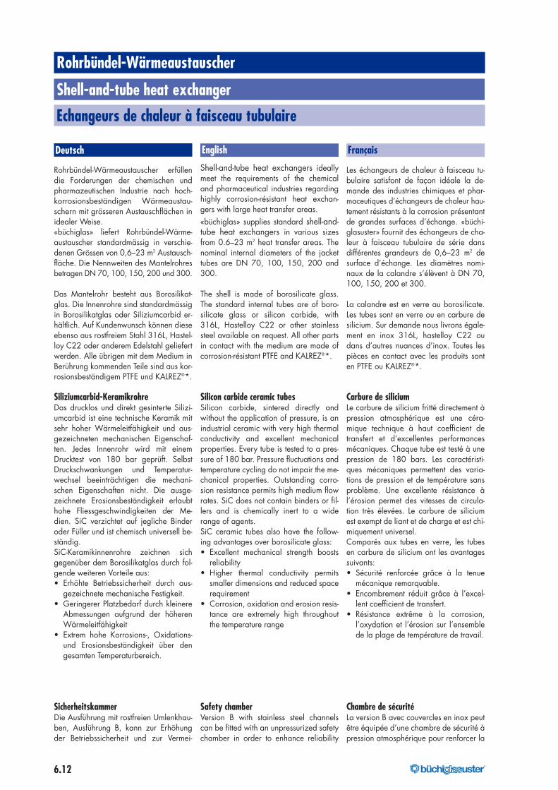
Rohrbündel-Wärmeaustauscher erfüllendie Forderungen der chemischen undpharmazeutischen Industrie nach hoch-korrosionsbeständigen Wärmeaustau-schern mit grösseren Austauschflächen inidealer Weise.«büchiglas» liefert Rohrbündel-Wärme-austauscher standardmässig in verschie-denen Grössen von 0,6–23 m2 Austausch-fläche. Die Nennweiten des Mantelrohresbetragen DN 70, 100, 150, 200 und 300.
Das Mantelrohr besteht aus Borosilikat-glas. Die Innenrohre sind standardmässigin Borosilikatglas oder Siliziumcarbid er-hältlich. Auf Kundenwunsch können dieseebenso aus rostfreiem Stahl 316L, Hastel-loy C22 oder anderem Edelstahl geliefertwerden. Alle übrigen mit dem Medium inBerührung kommenden Teile sind aus kor-rosionsbeständigem PTFE und KALREZ®*.
Siliziumcarbid-KeramikrohreDas drucklos und direkt gesinterte Silizi-umcarbid ist eine technische Keramik mitsehr hoher Wärmeleitfähigkeit und aus-gezeichneten mechanischen Eigenschaf-ten. Jedes Innenrohr wird mit einemDrucktest von 180 bar geprüft. SelbstDruckschwankungen und Temperatur-wechsel beeinträchtigen die mechani-schen Eigenschaften nicht. Die ausge-zeichnete Erosionsbeständigkeit erlaubthohe Fliessgeschwindigkeiten der Me-dien. SiC verzichtet auf jegliche Binderoder Füller und ist chemisch universell be-ständig.SiC-Keramikinnenrohre zeichnen sichgegenüber dem Borosilikatglas durch fol-gende weiteren Vorteile aus:• Erhöhte Betriebssicherheit durch aus-
gezeichnete mechanische Festigkeit.• Geringerer Platzbedarf durch kleinere
Abmessungen aufgrund der höherenWärmeleitfähigkeit
• Extrem hohe Korrosions-, Oxidations-und Erosionsbeständigkeit über dengesamten Temperaturbereich.
SicherheitskammerDie Ausführung mit rostfreien Umlenkhau-ben, Ausführung B, kann zur Erhöhungder Betriebssicherheit und zur Vermei-
Shell-and-tube heat exchangers ideallymeet the requirements of the chemicaland pharmaceutical industries regardinghighly corrosion-résistant heat exchan-gers with large heat transfer areas.«büchiglas» supplies standard shell-and-tube heat exchangers in various sizesfrom 0.6–23 m2 heat transfer areas. Thenominal internal diameters of the jackettubes are DN 70, 100, 150, 200 and300.
The shell is made of borosilicate glass.The standard internal tubes are of boro-silicate glass or silicon carbide, with316L, Hastelloy C22 or other stainlesssteel available on request. All other partsin contact with the medium are made ofcorrosion-résistant PTFE and KALREZ®*.
Silicon carbide ceramic tubesSilicon carbide, sintered directly andwithout the application of pressure, is anindustrial ceramic with very high thermalconductivity and excellent mechanicalproperties. Every tube is tested to a pres-sure of 180 bar. Pressure fluctuations andtemperature cycling do not impair the me-chanical properties. Outstanding corro-sion resistance permits high medium flowrates. SiC does not contain binders or fil-lers and is chemically inert to a widerange of agents.SiC ceramic tubes also have the follow-ing advantages over borosilicate glass:• Excellent mechanical strength boosts
reliability• Higher thermal conductivity permits
smaller dimensions and reduced spacerequirement
• Corrosion, oxidation and erosion resis-tance are extremely high throughoutthe temperature range
Safety chamberVersion B with stainless steel channelscan be fitted with an unpressurized safetychamber in order to enhance reliability
Les échangeurs de chaleur à faisceau tu-bulaire satisfont de façon idéale la de-mande des industries chimiques et phar-maceutiques d’échangeurs de chaleur hau-tement résistants à la corrosion présentantde grandes surfaces d’échange. «büchi-glasuster» fournit des échangeurs de cha-leur à faisceau tubulaire de série dansdifférentes grandeurs de 0,6–23 m2 desurface d’échange. Les diamètres nomi-naux de la calandre s’élèvent à DN 70,100, 150, 200 et 300.
La calandre est en verre au borosilicate.Les tubes sont en verre ou en carbure desilicium. Sur demande nous livrons égale-ment en inox 316L, hastelloy C22 oudans d’autres nuances d’inox. Toutes lespièces en contact avec les produits sonten PTFE ou KALREZ®*.
Carbure de siliciumLe carbure de silicium fritté directement àpression atmosphérique est une céra-mique technique à haut coefficient detransfert et d’excellentes performancesmécaniques. Chaque tube est testé à unepression de 180 bars. Les caractéristi-ques mécaniques permettent des varia-tions de pression et de température sansproblème. Une excellente résistance àl’érosion permet des vitesses de circula-tion très élevées. Le carbure de siliciumest exempt de liant et de charge et est chi-miquement universel.Comparés aux tubes en verre, les tubesen carbure de silicium ont les avantagessuivants:• Sécurité renforcée grâce à la tenue
mécanique remarquable.• Encombrement réduit grâce à l’excel-
lent coefficient de transfert.• Résistance extrême à la corrosion,
l’oxydation et l’érosion sur l’ensemblede la plage de température de travail.
Chambre de sécuritéLa version B avec couvercles en inox peutêtre équipée d’une chambre de sécurité àpression atmosphérique pour renforcer la
Rohrbündel-Wärmeaustauscher
Shell-and-tube heat exchanger
Echangeurs de chaleur à faisceau tubulaire
Deutsch English Français
176040_buechi_Kapitel_6_Waermetauscher_mit Pantone_176040_buechi_Kapitel_6_Waermeaustauscher 07.07.17 07:11 Seite 12
6.13®
dung von Cross-Kontaminationen zwi-schen Prozess- und Serviceseite mit einerdrucklosen Sicherheitskammer ausgerüs-tet werden. Die sich zwischen der PTFE-Lochplatte und der Umlenkhaube befin-dende Zwischenplatte bildet den Hohl-raum für die Sicherheitskammer. Dieseverhindert, dass der Druck des Kühlmedi-ums direkt auf die PTFE-Lochplatte wirkenkann. Die bei einer allfälligen Undichtheitaustretende Flüssigkeit, produkt- oderkühlseitig, wird im Hohlraum derZwischenplatte aufgefangen und über ei-ne Öffnung kontrolliert abgeleitet. Fernerbesteht die Möglichkeit, über das optio-nale Anschliessen eines Flüssigkeitsde-tektors eine allfällige Leckage an eineWarte zu signalisieren.
CE-KennzeichnungDie Rohrbündel-Wärmeaustauscher wer-den in Übereinstimmung mit der harmoni-sierten Europäischen Druckgeräte-Richtli-nie 97/23/EG (PED) sowie der NormEN 1595 (Druckbehälter aus Glas) aus-gelegt, gefertigt und geprüft. Die Konfor-mität wird mit dem CE- Zeichen am Appa-rat und einer Konformitätserklärung be-stätigt.
Sei es als Einzelaggregat oder innerhalbeiner kompletten Glasinstallation: «büchi-glas»-Rohrbündel-Wärmeaustauscher bie-ten eindeutige Vorteile wie:• Universelle Korrosionsbeständigkeit• Ausgezeichneten Wärmeübergang• Bleibende Dichtheit dank Einsatz von
KALREZ®-Dichtungen für die Abdich-tung der Innenrohre
• Geringste Druckverluste• Kompakte Bauweise im Baukastensys-
tem• Servicefreundliche Konstruktion
Der besondere Vorteil der Rohrbündel-Wärmeaustauscher liegt in den hohenWärmeübertragsleistungen.
and prevent cross-contamination betweenthe process and service sides. The back-ingplate located between the PTFE tubesheet and the channel forms the cavity forthe safety chamber, which keeps the pres-sure of the coolant from acting directly onthe PTFE tube sheet. Liquid escaping onthe product or coolant side in case ofleaks is trapped in the cavity of the back-ing plate and discharged in controlledfashion through a port. If an optionalliquid detector is installed, any leaks oc-curring can also be reported on a controlpanel.
CE MarkingTubular heat exchangers are designed,manufactured and tested in accordancewith harmonized European PressureEquipment Directive 97/23/EG (PED)and standard EN 1595 (glass pressurevessels). Conformity is indicated by theCE symbol on the equipment togetherwith a declaration of conformity.
Whether as an individual unit or as partof a complete glass installation, «büchi-glas» shell and tube heat exchangersoffer distinctive advantages such as:• Virtually unlimited corrosion resistance• Excellent heat transfer characteristics• Permanent tightness due to the use of
KALREZ® gaskets for sealing the inter-nal tubes
• Extremely low pressure loss• Compact, modular design• Simple servicing requirements
The particular advantage offered by thetube-type heat exchangers is the veryhigh heat transfer performance.
sécurité et éviter une contamination croi-sée.Une deuxième plaque entre la plaque tu-bulaire en PTFE et le capot en inox mé-nage un espace pour la chambre de sé-curité, ce qui permet d’éviter que la pres-sion du fluide de refroidissement nes’exerce directement sur la plaque enPTFE.En cas de défaut d’étanchéité côté pro-duit ou côté fluide de refroidissement, lafuite se retrouve dans la chambre de sé-curité et est évacuée par un orifice, ce quipermet un contrôle visuel.
Marquage CELes échangeurs tubulaires sont fabriquéset contrôlés dans le respect des normeseuropéennes concernant les appareils àpression 97/23 CE (PED) ainsi que lanorme EN 1595. Cette conformité leurpermet d’être estampillés CE.
Que ce soit sous la forme d’un appareilindépendant ou à l’intérieur d’une instal-lation complète en verre: les échangeursde chaleur à faisceau tubulaire «büchi-glas» offrent des avantages uniques telsque:• résistance universelle à la corrosiorn• transfert de chaleur exceptionnel• étanchéité durable par l’utilisation de
joints KALREZ® pour l’étanchéité destubes intérieurs
• perte de pression minimale• construction compacte dans un sys-
tème modulaire• construction facilitant le service.
L’avantage particulier de l’échangeur dechaleur à faisceau tubulaire réside dansses performances de transmission de cha-leur élevées.
* Kalrez® ist ein eingetragenes Markenzeichen von DuPont Elastomers* Kalrez® is a registered trademark of DuPont Elastomers* Kalrez® est une marque déposée de DuPont Dow Elastomers
176040_buechi_Kapitel_6_Waermetauscher_mit Pantone_176040_buechi_Kapitel_6_Waermeaustauscher 07.07.17 07:11 Seite 13
6.14 ®
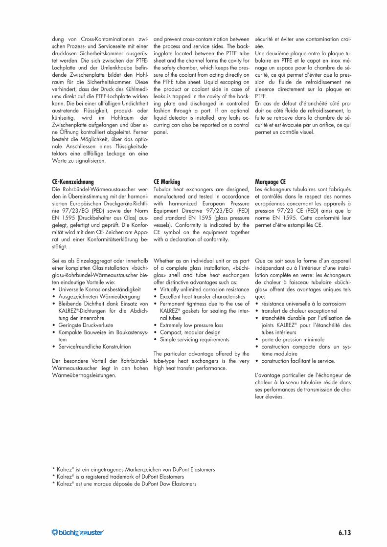
Typ A – Rohrbündelwärmetauscher Typ Amit Glashaube und Glasinnenrohren.
Typ A Shell and tube heat exchangerwith glass dome and glass tubes inside.
Echangeur tubulaire type A avec dômeen verre et tubes internes en verre.
Typ B – Rohrbündelwärmetauscher mitStahlumlenkhaube und Glasinnenrohren.
Typ B Shell and tube heat exchangerwith flow guide dome and glass tubesinside.
Echangeur tubulaire type B avec cou-vercle de renvoi en acier et tubesinternes en verre.
Rohrbündelwärmetauscher mit Stahl-umlenkhaube und Sicherheitskammerund SiC-Innenrohren.
Shell and tube heat exchanger with steeldome and safety chamber and SiC tubesinside.
Echangeur tubulaire type B avecchambre de sécurité et tubes internesen SiC.
LeistungsdatenZur überschlägigen Berechnung von Aus-tauscherflächen können folgende Richt-werte für den Wärmedurchgangkoeffi-zienten k zugrunde gelegt werden:
Flüssig-flüssig-AustauschBorosilikatglas: k = 150…550 W/m2 KSic: k = 750…2500 W/m2 K
KondensationBorosilikatglas: k = 500…700 W/m2 KSic: k = 1500…3000 W/m2 K
Die Einsatzbereiche (Druck und Tempera-tur) für die verschiedenen Ausführungensind den Apparatebeschreibungen aufden Seiten 6.19 zu entnehmen.
Performance dataThe guide value ranges of the heat transi-tion coefficient k for the approximate cal-culation of heat transfer areas are as fol-lows.
Liquid-liquid exchangeBorosilicate glass: k = 150…550 W/m2 KSic: k = 750…2500 W/m2 K
CondensationBorosilicate glass: k = 500…700 W/m2 KSic: k = 1500…3000 W/m2 K
See the apparatus descriptions on pages6.19 for the pressure and temperatureranges of the various versions.
PerformancesLes valeurs indicatives de coefficient detransmission thermique k suivantespeuvent être prises comme base pour lecalcul approximatif des surfaces d’échan-geur.
Echange liquide-liquideverre au borosilicate:k = 150…550 W/m2 KSic: k = 750…2500 W/m2 K
Condensationverre au borosilicate:k = 500…700 W/m2 KSic: k = 1500…3000 W/m2 KLes champs d’application (pression ettempérature) des exécutions les plus di-verses sont mentionnés dans les descrip-tions d’appareils à la page 6.19.
176040_buechi_Kapitel_6_Waermetauscher_mit Pantone_176040_buechi_Kapitel_6_Waermeaustauscher 07.07.17 07:11 Seite 14
6.15®
Rohrbündel-Wärmeaustauscher
Shell-and-tube heat exchanger
Echangeur de chaleur à faisceau tubulaire
Deutsch FrançaisEnglish
Rohrbündel-Wärmeaustauscher von «bü-chiglas» stehen in zwei verschiedenenGrundausführungen mit Austauschflächenvon 2,5–23 m2 zur Verfügung.
Ausführungen ARohr- und Mantelseite korrosionsfestDiese Ausführungen mit Glashauben eig-net sich bosonders für den Wärmeaus-tausch zwischen zwei aggressiven Me-dien. Die Innenrohre sind standardmäs-sig in Borosilikatglas oder Siliziumcarbiderhältlich. Auf Kundenwunsch könnendiese ebenso aus rostfreiem Stahl 316L,Hastelloy C22 oder anderem Edelstahlgeliefert werden. Alle übrigen mit demMedium in Berührung kommenden Teilesind aus korrosionsbeständigem PTFEund KALREZ®*.Bleibende Dichtheit, auch bei extremenBetriebsbedingungen, sind das Resultatdieser aufwändigen Abdichtung.
Technische Informationen zu den SiC-Innenrohren finden Sie auf Seite 6.19 indiesem Katalog.
Für die Ausführung A ist keine Sicher-heitskammer erhältlich!
«büchiglas» shell-and-tube heat exchan-gers are available in two basic configu-rations with heat transfer area from2.5–23 m2.
Configuration ACorrosion-resistant tube and jacketThis configuration with glass domes isparticularly suitable for the exchange ofheat between two aggressive media. Thestandard tubes are of borosilicate glassor silicon carbide, with 316L, HastelloyC22 or other stainless steel available onrequest. All other parts in contact with themedium are made of corrosion-resistantPTFE and KALREZ®*.This sophisticated sealing method resultsin joints that remain tight even under ex-treme operating conditions.
For specifications on SiC internal tubes,see on page 6.19 in this catalog.
The safety chamber is not available onversion A.
Les échangeurs de chaleur à faisceau tubu-laire de «büchiglas» sont disponibles dansdeux exécutions de base differentes offrantdes surfaces d'échange de 2,5–23 m2.
Exécution ACôté tube et enveloppe résistantà la corrosionCette exécution avec couvercles en verreconvient tout particulièrement pourl’échange de chaleur entre deux fluidesagressifs. Les tubes standard sont enverre au borosilicate ou en carbure de si-licium. Sur demande ils peuvent être éga-lement en inox 316L, en hastelloy C22ou dans une autre nuance d'inox. Toutesles autres pièces en contact avec les pro-duits sont en PTFE ou KALREZ®*.L’étanchéité permanente même dans desconditions d’exploitation extrêmes est ob-tenue par ce joint coûteux.
Vous trouverez les informations techni-ques concernant les tubes au carbure desilicium page 6.19 de ce catalogue.
La version A ne peut pas être fabriquéeavec une chambre de sécurité.
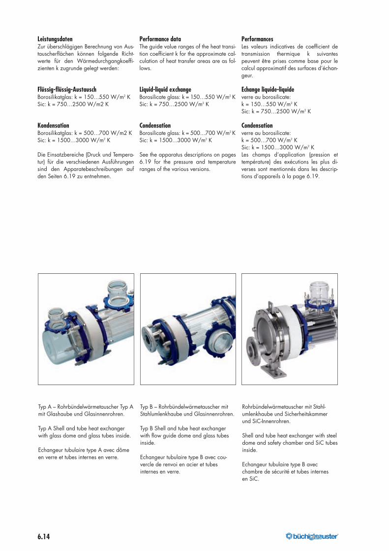
Rohrbündel-Wärmeaustauscher Ausführung AShell-and-tube heat exchanger, configuration AEchangeur de chaleur à faisceau tubulaire exécution A
176040_buechi_Kapitel_6_Waermetauscher_mit Pantone_176040_buechi_Kapitel_6_Waermeaustauscher 07.07.17 07:11 Seite 15
6.16 ®
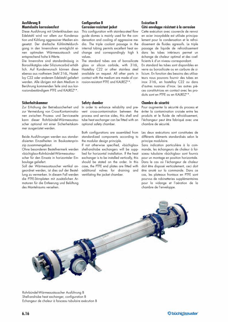
Ausführung BMantelseite korrosionsfestDiese Ausführung mit Umlenkhauben ausEdelstahl wird vor allem zur Kondensa-tion und Kühlung aggressiver Medien ein-gesetzt. Der dreifache Kühlmitteldurch-gang in den Innenrohren ermöglicht ei-nen optimalen Wärmeaustausch undentsprechend hohe k-Werte.Die Innenrohre sind standardmässig inBorosilikatglas oder Siliziumcarbid erhält-lich. Auf Kundenwunsch können dieseebenso aus rostfreiem Stahl 316L, Hastel-loy C22 oder anderem Edelstahl geliefertwerden. Alle übrigen mit dem Medium inBerührung kommenden Teile sind aus kor-rosionsbeständigem PTFE und KALREZ®*.
SicherheitskammerZur Erhöhung der Betriebssicherheit undzur Vermeidung von Cross-Kontaminatio-nen zwischen Prozess- und Serviceseitekann dieser Rohrbündel-Wärmeaustau-scher optional mit einer Sicherheitskam-mer ausgerüstet werden.
Beide Ausführungen werden aus standar-disierten Einzelheiten im Baukastenprin-zip zusammengebaut.Ohne besonderen Bestellvermerk werden«büchiglas»-Rohrbündel-Wärmeaustau-scher für den Einsatz in horizontaler Ein-baulage geliefert.Soll der Wärmeaustauscher vertikal an-geordnet werden, ist dies auf der Bestel-lung zu vermerken. In diesem Fall werdendie PTFE-Stirnplaten mit zusätzlichen Ar-maturen für die Entleerung und Belüftungdes Mantelraums versehen.
Configuration BCorrosion-resistant jacketThis configuration with stainless-steel flowguide domes is mainly used for the con-densation and cooling of aggressive me-dia. The triple coolant passage in theinternal tubing permits excellent heat ex-change and correspondingly high kvalues.The standard tubes are of borosilicateglass or silicon carbide, with 316L,Hastelloy C22 or other stainless steelavailable on request. All other parts incontact with the medium are made of cor-rosion-resistant PTFE and KALREZ®*.
Safety chamberIn order to enhance reliability and pre-vent cross-contamination between theprocess and service sides, this shell andtube heat exchanger can be fitted with anoptional safety chamber.
Both configurations are assembled fromstandardized components according tothe modular design principle.If not otherwise specified, «büchiglas»shell-and-tube exchangers will be supp-lied for horizontal installation. If the heatexchanger is to be installed vertically, thisshould be stated on the order. In thiscase, the PTFE end plates are fitted withadditional valves for draining andventilating the jacket chamber.
Exécution BCôté enveloppe résistant à la corrosionCette exécution avec couvercle de renvoien acier inoxydable est utilisée principa-lement pour la condensation et le refroi-dissement de fluides agressifs. Le triplepassage de liquide de refroidissementdans les tubes intérieurs permet unéchange de chaleur optimal et des coef-ficients k d’un niveau correspondant.En standard les tubes sont disponibles enverre au borosilicate ou en carbure de si-licium. En fonction des besoins des utilisa-teurs nous pouvons fournir des tubes eninox 316L, en hastelloy C22 ou dansd'autres nuances d'inox. Les autres piè-ces constitutrices en contact avec les pro-duits sont en PTFE ou en KALREZ®*.
Chambre de sécuritéPour augmenter la sécurité du process etéviter la contamination croisée entre lesproduits et le fluide de refroidissement,l'échangeur peut être fabriqué avec unechambre de sécurité.
Les deux exécutions sont constituées dedifférents éléments standardisés selon leprincipe modulaire.Sans indication particulière à la com-mande, les échangeurs de chaleur à fai-sceau tubulaire «büchiglas» sont fournispour un montage en position horizontale.Dans le cas où l’échangeur de chaleurdoit être disposé verticalement, ceci doitêtre anoté sur la commande. Dans cecas, les plateaux frontaux en PTFE sontpourvus de robinetteries supplémentairespour la vidange et l’aération de lachambre de l’enveloppe.
Les informations techniques sur les tubes
Rohrbündel-Wärmeaustauscher Ausführung BShell-and-tube heat exchanger, configuration BEchangeur de chaleur à faisceau tubulaire exécution B
176040_buechi_Kapitel_6_Waermetauscher_mit Pantone_176040_buechi_Kapitel_6_Waermeaustauscher 07.07.17 07:11 Seite 16
6.17®
Technische Informationen zu den SiC-Innenrohren sowie der Sicherheitskam-mer finden Sie auf Seite 6.6 in diesemKatalog.
Alle Austauschertypen können mantelsei-tig mit der «Glassprotect-P»-Glasbeschich-tung versehen werden.
Leistungsdaten und AuslegungRohrbündel-Wärmeaustauscher von «bü-chiglasuster» zeichnen sich durch hoheWärmeübertragungsleistungen aus.Das bewährte und wirtschaftliche Baukas-tensystem erlaubt eine kundenspezifischeAnpassung an die jeweils vorliegendeAufgabenstellung. Zur überschlägigen Be-rechnung von Austauschflächen sind inder nachstehenden Tabelle einige typi-sche Wärmedurchgangszahlen aufge-führt.
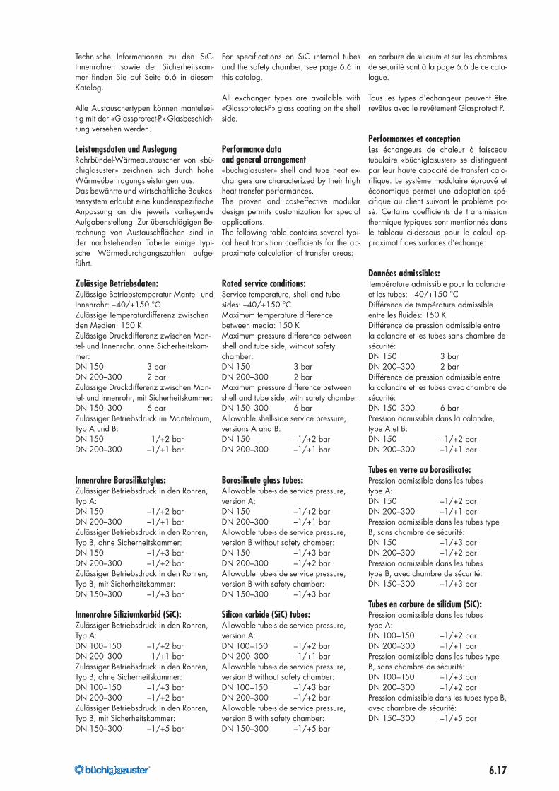
Zulässige Betriebsdaten:Zulässige Betriebstemperatur Mantel- undInnenrohr: –40/+150 °CZulässige Temperaturdifferenz zwischenden Medien: 150 KZulässige Druckdifferenz zwischen Man-tel- und Innenrohr, ohne Sicherheitskam-mer:DN 150 3 barDN 200–300 2 barZulässige Druckdifferenz zwischen Man-tel- und Innenrohr, mit Sicherheitskammer:DN 150–300 6 barZulässiger Betriebsdruck im Mantelraum,Typ A und B:DN 150 –1/+2 barDN 200–300 –1/+1 bar
Innenrohre Borosilikatglas:Zulässiger Betriebsdruck in den Rohren,Typ A:DN 150 –1/+2 barDN 200–300 –1/+1 barZulässiger Betriebsdruck in den Rohren,Typ B, ohne Sicherheitskammer:DN 150 –1/+3 barDN 200–300 –1/+2 barZulässiger Betriebsdruck in den Rohren,Typ B, mit Sicherheitskammer:DN 150–300 –1/+3 bar
Innenrohre Siliziumkarbid (SiC):Zulässiger Betriebsdruck in den Rohren,Typ A:DN 100–150 –1/+2 barDN 200–300 –1/+1 barZulässiger Betriebsdruck in den Rohren,Typ B, ohne Sicherheitskammer:DN 100–150 –1/+3 barDN 200–300 –1/+2 barZulässiger Betriebsdruck in den Rohren,Typ B, mit Sicherheitskammer:DN 150–300 –1/+5 bar
For specifications on SiC internal tubesand the safety chamber, see page 6.6 inthis catalog.
All exchanger types are available with«Glassprotect-P» glass coating on the shellside.
Performance dataand general arrangement«büchiglasuster» shell and tube heat ex-changers are characterized by their highheat transfer performances.The proven and cost-effective modulardesign permits customization for specialapplications.The following table contains several typi-cal heat transition coefficients for the ap-proximate calculation of transfer areas:
Rated service conditions:Service temperature, shell and tubesides: –40/+150 °CMaximum temperature differencebetween media: 150 KMaximum pressure difference betweenshell and tube side, without safetychamber:DN 150 3 barDN 200–300 2 barMaximum pressure difference betweenshell and tube side, with safety chamber:DN 150–300 6 barAllowable shell-side service pressure,versions A and B:DN 150 –1/+2 barDN 200–300 –1/+1 bar
Borosilicate glass tubes:Allowable tube-side service pressure,version A:DN 150 –1/+2 barDN 200–300 –1/+1 barAllowable tube-side service pressure,version B without safety chamber:DN 150 –1/+3 barDN 200–300 –1/+2 barAllowable tube-side service pressure,version B with safety chamber:DN 150–300 –1/+3 bar
Silicon carbide (SiC) tubes:Allowable tube-side service pressure,version A:DN 100–150 –1/+2 barDN 200–300 –1/+1 barAllowable tube-side service pressure,version B without safety chamber:DN 100–150 –1/+3 barDN 200–300 –1/+2 barAllowable tube-side service pressure,version B with safety chamber:DN 150–300 –1/+5 bar
en carbure de silicium et sur les chambresde sécurité sont à la page 6.6 de ce cata-logue.
Tous les types d'échangeur peuvent êtrerevêtus avec le revêtement Glasprotect P.
Performances et conceptionLes échangeurs de chaleur à faisceautubulaire «büchiglasuster» se distinguentpar leur haute capacité de transfert calo-rifique. Le système modulaire éprouvé etéconomique permet une adaptation spé-cifique au client suivant le problème po-sé. Certains coefficients de transmissionthermique typiques sont mentionnés dansle tableau ci-dessous pour le calcul ap-proximatif des surfaces d’échange:
Données admissibles:Température admissible pour la calandreet les tubes: –40/+150 °CDifférence de température admissibleentre les fluides: 150 KDifférence de pression admissible entrela calandre et les tubes sans chambre desécurité:DN 150 3 barDN 200–300 2 barDifférence de pression admissible entrela calandre et les tubes avec chambre desécurité:DN 150–300 6 barPression admissible dans la calandre,type A et B:DN 150 –1/+2 barDN 200–300 –1/+1 bar
Tubes en verre au borosilicate:Pression admissible dans les tubestype A:DN 150 –1/+2 barDN 200–300 –1/+1 barPression admissible dans les tubes typeB, sans chambre de sécurité:DN 150 –1/+3 barDN 200–300 –1/+2 barPression admissible dans les tubestype B, avec chambre de sécurité:DN 150–300 –1/+3 bar
Tubes en carbure de silicium (SiC):Pression admissible dans les tubestype A:DN 100–150 –1/+2 barDN 200–300 –1/+1 barPression admissible dans les tubes typeB, sans chambre de sécurité:DN 100–150 –1/+3 barDN 200–300 –1/+2 barPression admissible dans les tubes type B,avec chambre de sécurité:DN 150–300 –1/+5 bar
176040_buechi_Kapitel_6_Waermetauscher_mit Pantone_176040_buechi_Kapitel_6_Waermeaustauscher 07.07.17 07:11 Seite 17
6.18 ®
Rohrbündel-Wärmeaustauscher, Ausführung A, ohne Sicherheitskammer
Shell-and-tube heat exchanger, typeA, without safety chamber
Echangeurs de chaleur à faisceau tubulaire, exécution A, sans chambre de sécurité
Deutsch FrançaisEnglish
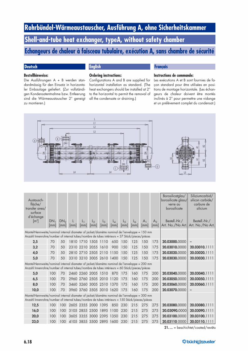
Bestellhinweise:Die Ausführungen A + B werden stan-dardmässig für den Einsatz in horizonta-ler Einbaulage geliefert. (Zur vollständi-gen Kondensatentnahme bzw. Entleerungsind die Wärmeaustauscher 2° geneigtzu montieren.)
Ordering instructions:Configurations A and B are supplied forhorizontal installation as standard. (Theheat exchangers should be installed at 2°to the horizontal to permit the removal ofall the condensate or draining.)
Instructions de commande:Les exécutions A et B sont fournies de fa-çon standard pour être utilisées en posi-tions de montage horizontale. (Les échan-geurs de chaleur doivent être montésinclinés à 2° pour permettre une vidangeet un prélèvement complet du condensat.)
DN1DN2
DN2DN1
A
DC
B
L3
DN
L1
L4
DN
L2
L4 L5L6
A1 A2
A1 A2
L
Borosilicatglas/ Siliziumcarbid/Austausch- borosilicate glass/ silicon carbide/
fläche/ verre au carbure detransfer area/ borosilicate silicium
surfaced’échange
[m2] DN1 DN2 L L1 L2 L3 L4 L5 L6 A1 A2 Bestell.-Nr./ Bestell.-Nr./[mm] [mm] [mm] [mm] [mm] [mm] [mm] [mm] [mm] [mm] [mm] Art. No./No Art. Art. No./No Art.
Mantel-Nennweite/nominal internal diameter of jacket/diamètre nominal de l’enveloppe = 150 mmAnzahl Innenrohre/number of internal tubes/nombre de tubes intérieurs = 37 Stück/pieces/pièces
2,5 70 50 1810 1710 1505 1110 650 150 125 150 175 20.03000.0000 –3,2 70 50 2310 2210 2055 1610 900 150 125 150 175 20.03010.0000 20.03010.11114,0 70 50 2810 2710 2505 2110 1150 150 125 150 175 20.03020.0000 20.03020.11115,0 70 50 3310 3210 3005 2610 1400 150 125 150 175 20.03030.0000 20.03030.1111
Mantel-Nennweite/nominal internal diameter of jacket/diamètre nominal de l’enveloppe = 200 mmAnzahl Innenrohre/number of internal tubes/nombre de tubes intérieurs = 60 Stück/pieces/pièces
5,0 100 70 2460 2260 2005 1510 870 175 160 175 200 20.03040.0000 20.03040.11116,5 100 70 2960 2760 2505 2010 1120 175 160 175 200 20.03050.0000 20.03050.11118,0 100 70 3460 3260 3005 2510 1370 175 160 175 200 20.03060.0000 20.03060.111110,0 100 70 3960 3760 3505 3010 1620 175 160 175 200 20.03070.0000 –
Mantel-Nennweite/nominal internal diameter of jacket/diamètre nominal de l’enveloppe = 300 mmAnzahl Innenrohre/number of internal tubes/nombre de tubes intérieurs = 150 Stück/pieces/pièces
12,5 100 100 2605 2355 2000 1395 850 230 215 275 275 20.03080.0000 20.03080.111116,0 100 100 3105 2855 2500 1895 1100 230 215 275 275 20.03090.0000 20.03090.111120,0 100 100 3605 3355 3000 2395 1350 230 215 275 275 20.03100.0000 20.03100.111123,0 100 100 4105 3855 3500 2895 1600 230 215 275 275 20.03110.0000 20.03110.1111
21. … = beschichtet/coated/revêtu
176040_buechi_Kapitel_6_Waermetauscher_mit Pantone_176040_buechi_Kapitel_6_Waermeaustauscher 07.07.17 07:11 Seite 18
6.19®
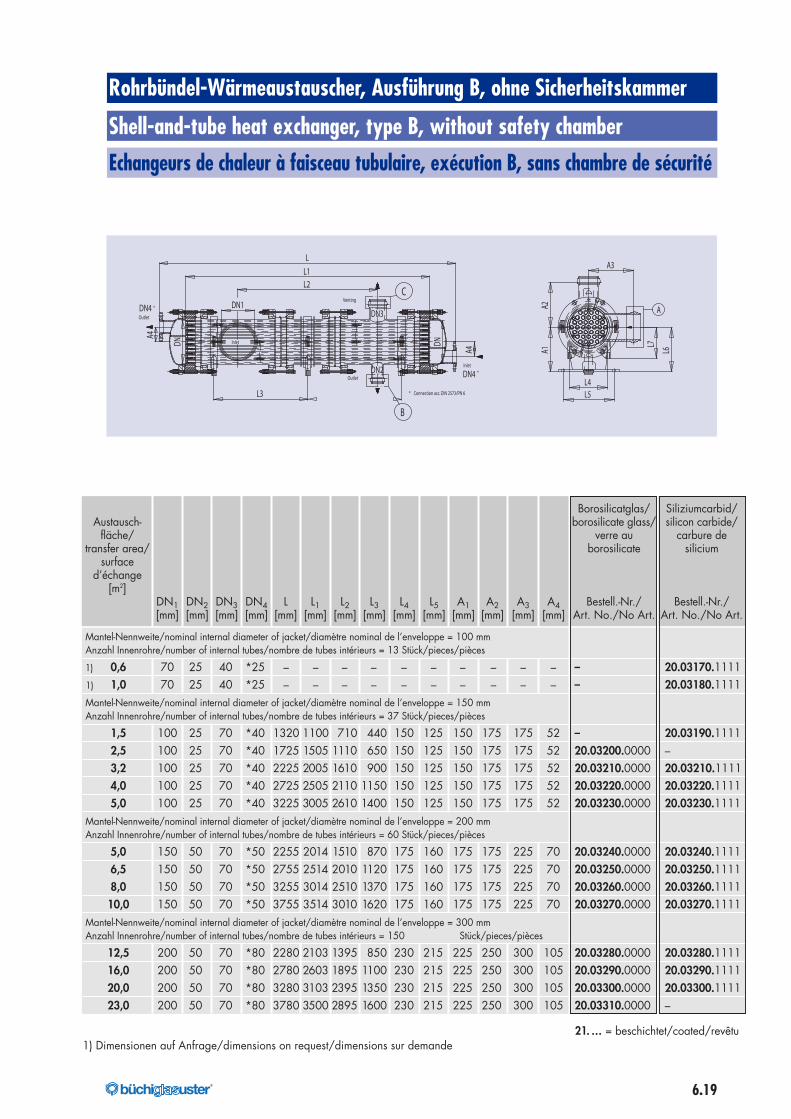
Rohrbündel-Wärmeaustauscher, Ausführung B, ohne Sicherheitskammer
Shell-and-tube heat exchanger, type B, without safety chamber
Echangeurs de chaleur à faisceau tubulaire, exécution B, sans chambre de sécurité
A
L5
L6
L7
A1A2
L4
A3
Borosilicatglas/ Siliziumcarbid/Austausch- borosilicate glass/ silicon carbide/
fläche/ verre au carbure detransfer area/ borosilicate silicium
surfaced’échange
[m2]DN1 DN2 DN3 DN4 L L1 L2 L3 L4 L5 A1 A2 A3 A4 Bestell.-Nr./ Bestell.-Nr./[mm] [mm] [mm] [mm] [mm] [mm] [mm] [mm] [mm] [mm] [mm] [mm] [mm] [mm] Art. No./No Art. Art. No./No Art.
Mantel-Nennweite/nominal internal diameter of jacket/diamètre nominal de l’enveloppe = 100 mmAnzahl Innenrohre/number of internal tubes/nombre de tubes intérieurs = 13 Stück/pieces/pièces
1) 0,6 70 25 40 *25 – – – – – – – – – – – 20.03170.11111) 1,0 70 25 40 *25 – – – – – – – – – – – 20.03180.1111Mantel-Nennweite/nominal internal diameter of jacket/diamètre nominal de l’enveloppe = 150 mmAnzahl Innenrohre/number of internal tubes/nombre de tubes intérieurs = 37 Stück/pieces/pièces
1,5 100 25 70 *40 1320 1100 710 440 150 125 150 175 175 52 – 20.03190.11112,5 100 25 70 *40 1725 1505 1110 650 150 125 150 175 175 52 20.03200.0000 –3,2 100 25 70 *40 2225 2005 1610 900 150 125 150 175 175 52 20.03210.0000 20.03210.11114,0 100 25 70 *40 2725 2505 2110 1150 150 125 150 175 175 52 20.03220.0000 20.03220.11115,0 100 25 70 *40 3225 3005 2610 1400 150 125 150 175 175 52 20.03230.0000 20.03230.1111
Mantel-Nennweite/nominal internal diameter of jacket/diamètre nominal de l’enveloppe = 200 mmAnzahl Innenrohre/number of internal tubes/nombre de tubes intérieurs = 60 Stück/pieces/pièces
5,0 150 50 70 *50 2255 2014 1510 870 175 160 175 175 225 70 20.03240.0000 20.03240.11116,5 150 50 70 *50 2755 2514 2010 1120 175 160 175 175 225 70 20.03250.0000 20.03250.11118,0 150 50 70 *50 3255 3014 2510 1370 175 160 175 175 225 70 20.03260.0000 20.03260.111110,0 150 50 70 *50 3755 3514 3010 1620 175 160 175 175 225 70 20.03270.0000 20.03270.1111
Mantel-Nennweite/nominal internal diameter of jacket/diamètre nominal de l’enveloppe = 300 mmAnzahl Innenrohre/number of internal tubes/nombre de tubes intérieurs = 150 Stück/pieces/pièces
12,5 200 50 70 *80 2280 2103 1395 850 230 215 225 250 300 105 20.03280.0000 20.03280.111116,0 200 50 70 *80 2780 2603 1895 1100 230 215 225 250 300 105 20.03290.0000 20.03290.111120,0 200 50 70 *80 3280 3103 2395 1350 230 215 225 250 300 105 20.03300.0000 20.03300.111123,0 200 50 70 *80 3780 3500 2895 1600 230 215 225 250 300 105 20.03310.0000 –
1) Dimensionen auf Anfrage/dimensions on request/dimensions sur demande21. … = beschichtet/coated/revêtu
Outlet
Inlet
Outlet
Venting
Inlet
Connection acc. DIN 2573/PN 6*
*
*
C
B
DN4
DN4
DN3
DN2
A4
DN1
A4
L
DN
L3
DN
L2L1
176040_buechi_Kapitel_6_Waermetauscher_mit Pantone_176040_buechi_Kapitel_6_Waermeaustauscher 07.07.17 07:11 Seite 19
6.20 ®
Borosilicatglas/ Siliziumcarbid/Austausch- borosilicate glass/ silicon carbide/
fläche/ verre au carbire detransfer area/ borosilicate silicium
surfaced’echange
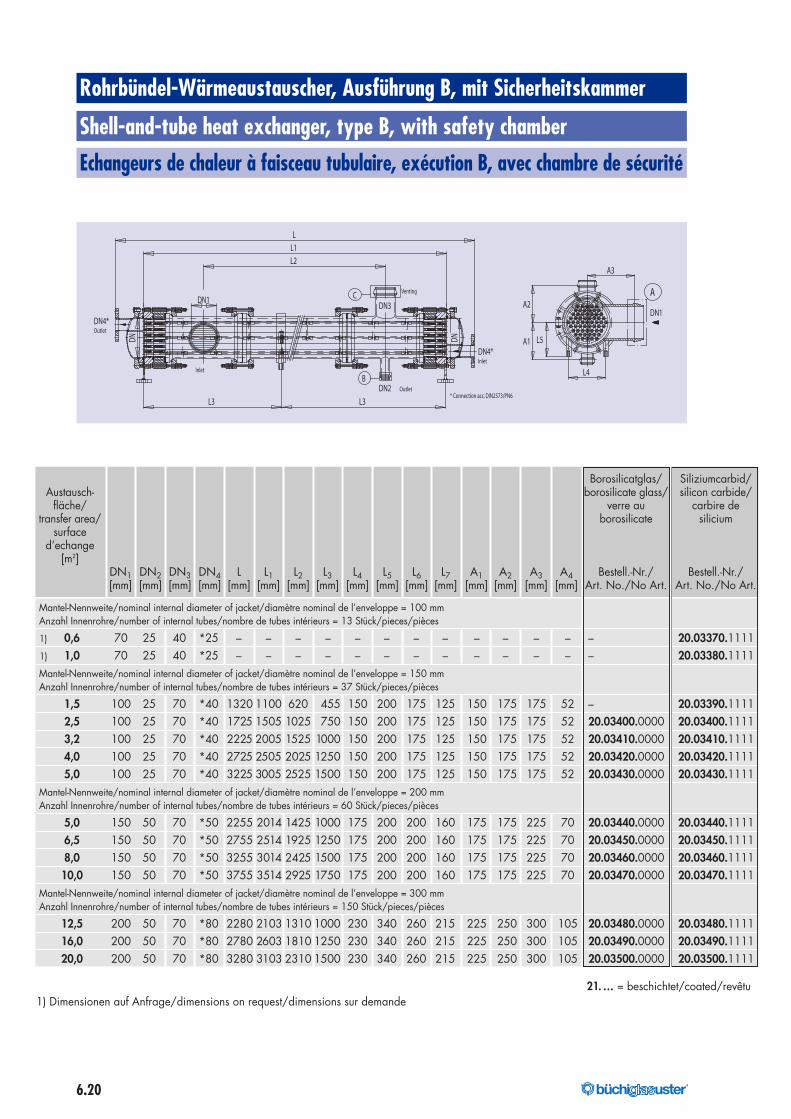
[m2]DN1 DN2 DN3 DN4 L L1 L2 L3 L4 L5 L6 L7 A1 A2 A3 A4 Bestell.-Nr./ Bestell.-Nr./[mm] [mm] [mm] [mm] [mm] [mm] [mm] [mm] [mm] [mm] [mm] [mm] [mm] [mm] [mm] [mm] Art. No./No Art. Art. No./No Art.
Mantel-Nennweite/nominal internal diameter of jacket/diamètre nominal de l’enveloppe = 100 mmAnzahl Innenrohre/number of internal tubes/nombre de tubes intérieurs = 13 Stück/pieces/pièces
1) 0,6 70 25 40 *25 – – – – – – – – – – – – – 20.03370.11111) 1,0 70 25 40 *25 – – – – – – – – – – – – – 20.03380.1111Mantel-Nennweite/nominal internal diameter of jacket/diamètre nominal de l’enveloppe = 150 mmAnzahl Innenrohre/number of internal tubes/nombre de tubes intérieurs = 37 Stück/pieces/pièces
1,5 100 25 70 *40 1320 1100 620 455 150 200 175 125 150 175 175 52 – 20.03390.11112,5 100 25 70 *40 1725 1505 1025 750 150 200 175 125 150 175 175 52 20.03400.0000 20.03400.11113,2 100 25 70 *40 2225 2005 1525 1000 150 200 175 125 150 175 175 52 20.03410.0000 20.03410.11114,0 100 25 70 *40 2725 2505 2025 1250 150 200 175 125 150 175 175 52 20.03420.0000 20.03420.11115,0 100 25 70 *40 3225 3005 2525 1500 150 200 175 125 150 175 175 52 20.03430.0000 20.03430.1111
Mantel-Nennweite/nominal internal diameter of jacket/diamètre nominal de l’enveloppe = 200 mmAnzahl Innenrohre/number of internal tubes/nombre de tubes intérieurs = 60 Stück/pieces/pièces
5,0 150 50 70 *50 2255 2014 1425 1000 175 200 200 160 175 175 225 70 20.03440.0000 20.03440.11116,5 150 50 70 *50 2755 2514 1925 1250 175 200 200 160 175 175 225 70 20.03450.0000 20.03450.11118,0 150 50 70 *50 3255 3014 2425 1500 175 200 200 160 175 175 225 70 20.03460.0000 20.03460.111110,0 150 50 70 *50 3755 3514 2925 1750 175 200 200 160 175 175 225 70 20.03470.0000 20.03470.1111
Mantel-Nennweite/nominal internal diameter of jacket/diamètre nominal de l’enveloppe = 300 mmAnzahl Innenrohre/number of internal tubes/nombre de tubes intérieurs = 150 Stück/pieces/pièces
12,5 200 50 70 *80 2280 2103 1310 1000 230 340 260 215 225 250 300 105 20.03480.0000 20.03480.111116,0 200 50 70 *80 2780 2603 1810 1250 230 340 260 215 225 250 300 105 20.03490.0000 20.03490.111120,0 200 50 70 *80 3280 3103 2310 1500 230 340 260 215 225 250 300 105 20.03500.0000 20.03500.1111
1) Dimensionen auf Anfrage/dimensions on request/dimensions sur demande21. … = beschichtet/coated/revêtu
Rohrbündel-Wärmeaustauscher, Ausführung B, mit Sicherheitskammer
Shell-and-tube heat exchanger, type B, with safety chamber
Echangeurs de chaleur à faisceau tubulaire, exécution B, avec chambre de sécurité
A
DN1
A3
A2
L5
L4
A1
Inlet
Outlet
Outlet
Venting
Inlet
* Connection acc. DIN2573/PN6
DN4*
DN2
DN4*
CDN3
B
L3 L3
L2
L
L1
DN1
DN DN
176040_buechi_Kapitel_6_Waermetauscher_mit Pantone_176040_buechi_Kapitel_6_Waermeaustauscher 07.07.17 07:11 Seite 20
6.21®
Wärmeaustauscher aus Metall
Metal heat exchangers
Echangeurs de chaleur en métal
Deutsch FrançaisEnglish
Metall-Wärmeaustauscher werden über-all dort eingesetzt, wo Glas-Wärmeaus-tauscher durch die gegebenen Betriebs-drücke nicht mehr genügen. In der Praxiswerden sie vor allem als Heizer, die mitSattdampf beaufschlagt werden, einge-setzt.
Neben ausgezeichneten Wärmeübertra-gungsleistungen bieten Metall-Wärme-austauscher eine Reihe weiterer Vorteilewie:• Hohe Betriebssicherheit• Kompakte Bauweise und kleine
Austauschflächen• Keine Reduzierung des Heizdampf-
druckes in den meisten Fällen
Zum Bau von Metall-Wärmeaustauschernwerden vorwiegend folgende Metalleverwendet:• Hochlegierte Edelstähle 1.4435
und 1.4571• Hastelloy• Titan• Tantal
Tantal entspricht in seinem Korrosionsver-halten weitgehend dem von Borosilicat-glas und ist somit genauso universell ein-setzbar.
Aus der Vielzahl der möglichen Baufor-men sind im Lieferprogramm die folgen-den Typen enthalten, die sich problemlosin das «büchiglas»-Apparatebaupro-gramm einfügen.• Schlangen-Wärmeaustauscher• Einfach-Heizkerzen• Mehrfach-Heizkerzen
Heizkerzen werden hauptsächlich beiUmlaufverdampfern eingesetzt. Heizker-zen aus Tantal sind standardmässig mitAustauschflächen von 0,05–10 m2 liefer-bar. Durch die hohe Wärmeleitfähigkeitdes Materials und die optimale Konstruk-tion werden hervorragende Wärmeüber-tragungsleistungen erreicht.
Metal heat exchangers are used wher-ever the operating pressure exceeds themaximum permissible pressure for glassheat exchangers. In practical applica-tions, they are primarily used as heatersthat can be operated with saturatedsteam.
In addition to excellent heat transfer per-formances, metal heat exchangers offer aseries of additional advantages such as:• High operational safety• Compact design and small heat
transfer areas• No reduction of the heating-steam
pressure in most cases
The following metals are normally usedfor the manufacture of metal heat ex-changers:• High-alloy stainless steels 1.4435
and 1.4571• Hastelloy• Titanium• Tantalum
The corrosion behavior of tantalum isvery similar to that of borosilicate glass; itcan therefore be used for the same vir-tually unlimited range of applications.
From the multitude of possible configura-tions, the following types are included inthe heat exchanger line which form an in-tegral part of the «büchiglas» apparatusconstruction programme.• Spiral heat exchanger• Simple heating cartridges• Multiple heating cartridges
Heating cartridges are used mainly in cir-culation evaporators. Standard tantalumheating cartridges can be suppliedwith heat exchange areas from 0.05–10 m2. Outstanding heat transfer perfor-mances are achieved as a result of thehigh conductivity ot the material and theoptimized design.
Les échangeurs de chaleur métalliquessont utilisés partout où les échangeurs dechaleur en verre ne suffisent plus du faitdes pressions de service données. Dansla pratique, ils sont principalement utiliséscomme réchauffeurs fonctionnant à lavapeur saturée.
Les échangeurs de chaleur métalliquesoffrent, en dehors de performances detransfert de chaleur exceptionnelles, unesérie d’autres avantages tels que:• haute sécurité d’exploitation• construction compacte et petites
surfaces d’échange• pas de réduction de la pression de
vapeur de chauffage dans la plupartdes cas.
Les métaux suivants sont principalementutilisés pour la construction d’échangeursde chaleur métalliques:• aciers inoxydables à haute teneur
en alliage 1.4435 et 1.4571• hastelloy• titane• tantale
Le tantale correspond largement au verreau borosilicate du point de vue de soncomportement à la corrosion et en consé-quence est tout aussi utilisable universelle-ment.
A partir du grande nombre de formes deconstruction possibles, les types suivantsqui s’insèrent sans problème dans le pro-gramme du construction d’appareils«büchiglas» sont compris dans le pro-gramme de livraison.• Echangeurs de chaleur à serpentin• Bougies chauffantes simples• Bougies chauffantes multiples
Les bougies chauffantes sont principale-ment utilisées dans les évaporateurs àcirculation. Les bougies chauffantes entantale sont disponibles en série avec dessurfaces d’échange de 0,05–10 m2. Despuissances de transfert calorifiquesexceptionnelles sont obtenues du fait dela haute conductiblilité thermique dumatériau et de la construction optimale.
176040_buechi_Kapitel_6_Waermetauscher_mit Pantone_176040_buechi_Kapitel_6_Waermeaustauscher 07.07.17 07:11 Seite 21
6.22 ®
LeistungsdatenZur überschlägigen Berechnung von Aus-tauscherflächen für Metall-Wärmeaustau-scher kann folgender Richtwert für denWärmedurchgangskoeffizient k zugrun-de gelegt werden:
k = 1500…2500 W/m2 K
Für alle Bauformen liegen in der Praxisüberprüfte Auslegungsdaten vor, die eineexakte Berechnung ermöglichen.
Performance dataThe following guide value range of theheat transmission coefficient k can beused to calculate the approximate heattransfer areas for metal heat exchangers:
k = 1500…2500 W/m2 K
Empirical design data, which permitexact calculation, are available for allconfigurations.
PerformancesLa valeur indicative du coefficient detransmission thermique k peut être prisecomme base pour le calcul approximatifdes surface d’échangeurs de chaleur mé-talliques:
k = 1500…2500 W/m2 K
Des données de conception vérifiéesdans la pratique qui permettent un calculexact sont disponibles pour toutes les for-mes de construction.
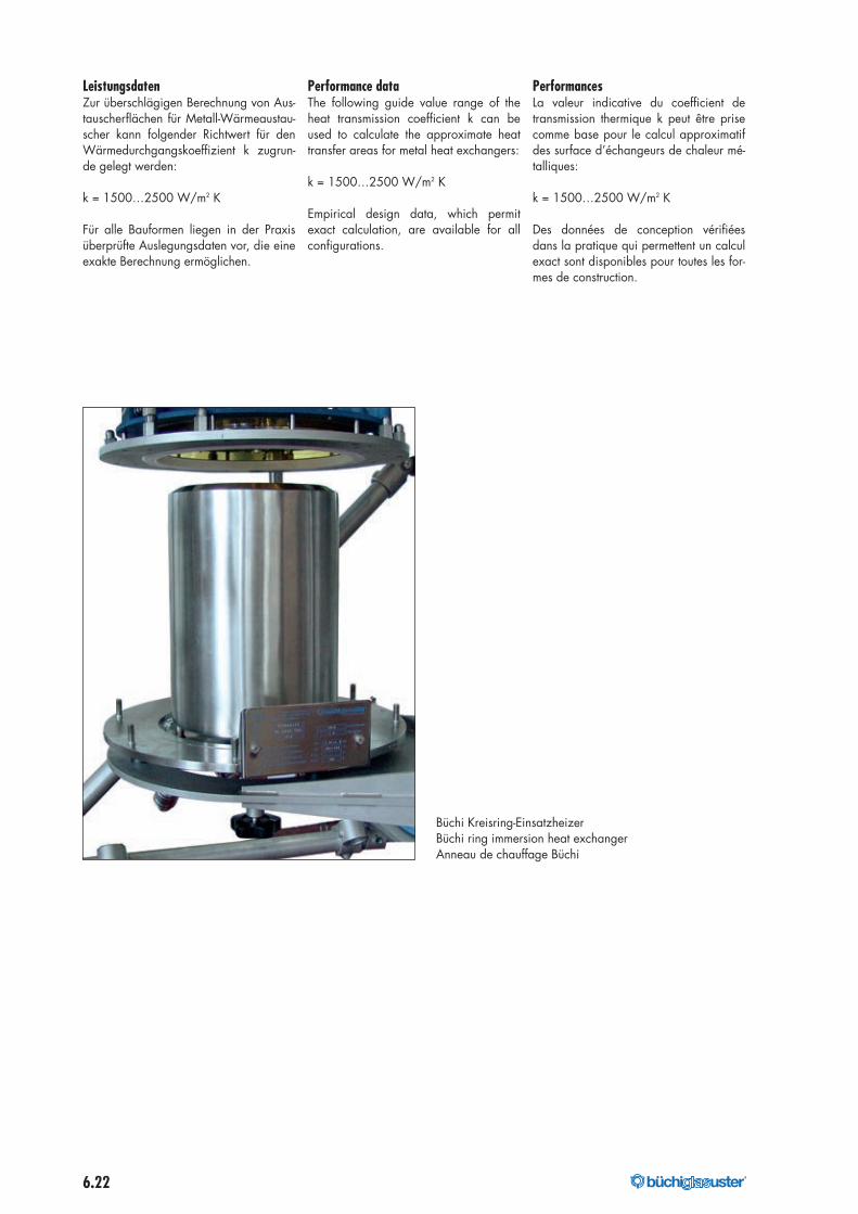
Büchi Kreisring-EinsatzheizerBüchi ring immersion heat exchangerAnneau de chauffage Büchi
176040_buechi_Kapitel_6_Waermetauscher_mit Pantone_176040_buechi_Kapitel_6_Waermeaustauscher 07.07.17 07:12 Seite 22
6.23®
Mehrfach-Heizkerze 0,1–10,0 m2
Multiple heating cartridge 0.1–10.0 m2
Bougie chauffante multiple 0,1–10,0 m2
Deutsch FrançaisEnglish
Diese Wärmeaustauscher mit mehrerenHeizkerzen werden hauptsächlich alsHeizer bei Umlaufverdampfern eingesetztund ermöglichen hohe Warmeübertra-gungsleistungen.
Der Einbau erfolgt bei DN 150 in einGlasrohr mit «büchiglas»-Planschliff. BeiDN 200–600 in ein Glasrohr mit «KF»-Planschliff.
Der Ablaufstutzen DN2 kann direkt mitdem «büchiglas»-Planschliff angeschlos-sen werden.
Einsatzbereiche für Tantal:zul. Betriebstemperatur:–10…+205 °Czul. Betriebsdruck inden Heizkerzen: 10 bar
These heat exchangers with multiple hea-ting cartridges are mainly used as heatersin circulation evaporators and permit highheat transfer capacities
The DN 150 size is built into a glass tubewith a «büchiglas» plane joint. The DN200–600 sizes are built into a glass tubewith a «KF» plane joint.
The DN2 drain connectors can be connec-ted directly to the «büchiglas» plane joint.
Operating ranges for Tantalum:Maximum operating temperatures:–10…+205 °CMaximum operating pressure in theheating cartridges: 10 bar
Ces échangeurs de chaleur avec plusieursbougies chauffantes sont principalementutilisés comme réchauffeurs dans les éva-porateurs à circulation et autorisent descapacités de transmission thermique éle-vées.
Le montage intervient en cas de DN 150dans un tube de verre à rodage plan«buchiglas» et pour les DN 200–600dans un tube de verre à rodage plan«KF».
Le raccord d’écoulement DN2peut être directement raccordé au rodageplan «büchiglas» et au raccord «PS».
Champs d’applications pour tantale:Température d’exploitation admissible:–10… +205 °CPression de service admissible dans lesbougies chauffantes: 10 bars
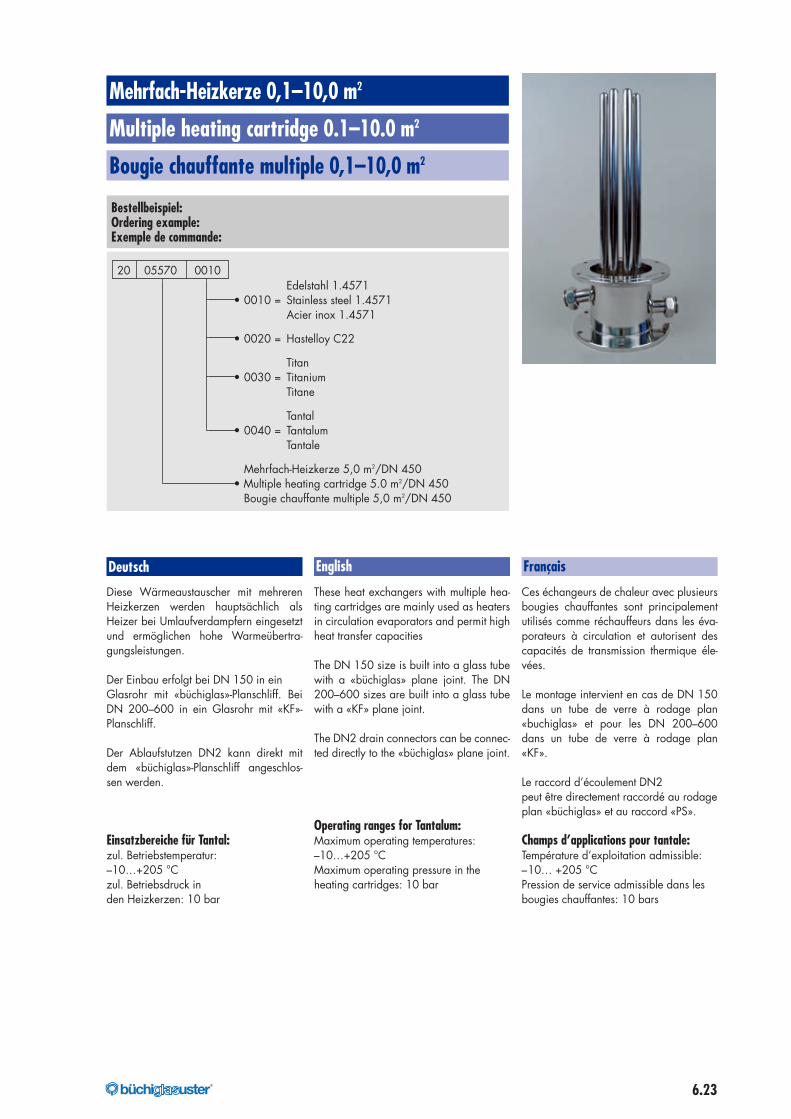
Bestellbeispiel:Ordering example:Exemple de commande:
Edelstahl 1.4571• 0010 = Stainless steel 1.4571
Acier inox 1.4571
• 0020 = Hastelloy C22
Titan• 0030 = Titanium
Titane
Tantal• 0040 = Tantalum
Tantale
Mehrfach-Heizkerze 5,0 m2/DN 450• Multiple heating cartridge 5.0 m2/DN 450
Bougie chauffante multiple 5,0 m2/DN 450
20 05570 0010
176040_buechi_Kapitel_6_Waermetauscher_mit Pantone_176040_buechi_Kapitel_6_Waermeaustauscher 07.07.17 07:12 Seite 23
6.24 ®
Deutsch FrançaisEnglish
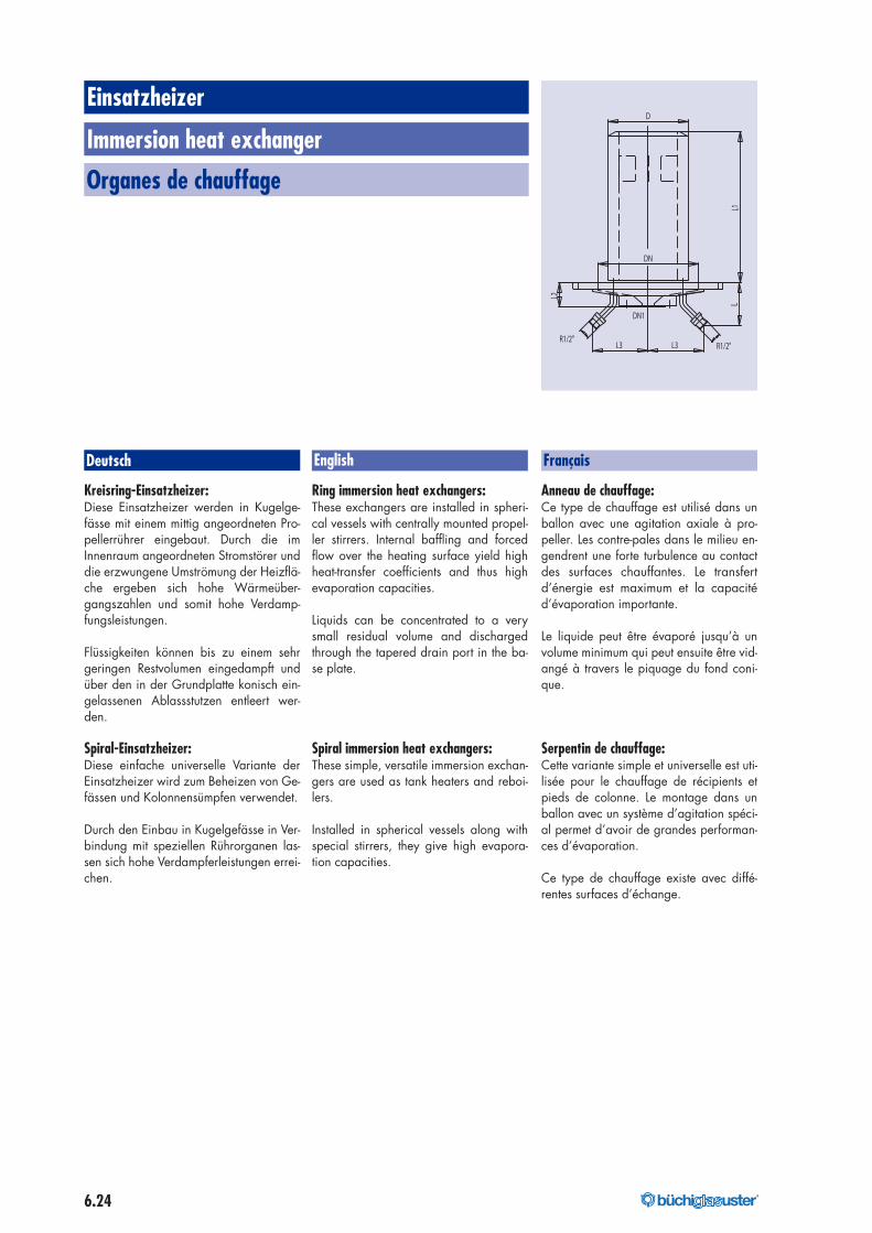
Kreisring-Einsatzheizer:Diese Einsatzheizer werden in Kugelge-fässe mit einem mittig angeordneten Pro-pellerrührer eingebaut. Durch die imInnenraum angeordneten Stromstörer unddie erzwungene Umströmung der Heizflä-che ergeben sich hohe Wärmeüber-gangszahlen und somit hohe Verdamp-fungsleistungen.
Flüssigkeiten können bis zu einem sehrgeringen Restvolumen eingedampft undüber den in der Grundplatte konisch ein-gelassenen Ablassstutzen entleert wer-den.
Spiral-Einsatzheizer:Diese einfache universelle Variante derEinsatzheizer wird zum Beheizen von Ge-fässen und Kolonnensümpfen verwendet.
Durch den Einbau in Kugelgefässe in Ver-bindung mit speziellen Rührorganen las-sen sich hohe Verdampferleistungen errei-chen.
Ring immersion heat exchangers:These exchangers are installed in spheri-cal vessels with centrally mounted propel-ler stirrers. Internal baffling and forcedflow over the heating surface yield highheat-transfer coefficients and thus highevaporation capacities.
Liquids can be concentrated to a verysmall residual volume and dischargedthrough the tapered drain port in the ba-se plate.
Spiral immersion heat exchangers:These simple, versatile immersion exchan-gers are used as tank heaters and reboi-lers.
Installed in spherical vessels along withspecial stirrers, they give high evapora-tion capacities.
Anneau de chauffage:Ce type de chauffage est utilisé dans unballon avec une agitation axiale à pro-peller. Les contre-pales dans le milieu en-gendrent une forte turbulence au contactdes surfaces chauffantes. Le transfertd’énergie est maximum et la capacitéd’évaporation importante.
Le liquide peut être évaporé jusqu’à unvolume minimum qui peut ensuite être vid-angé à travers le piquage du fond coni-que.
Serpentin de chauffage:Cette variante simple et universelle est uti-lisée pour le chauffage de récipients etpieds de colonne. Le montage dans unballon avec un système d’agitation spéci-al permet d’avoir de grandes performan-ces d’évaporation.
Ce type de chauffage existe avec diffé-rentes surfaces d’échange.
Einsatzheizer
Immersion heat exchanger
Organes de chauffage
DN1
D
L3 L3
LL1
R1/2"R1/2"
L2
DN
176040_buechi_Kapitel_6_Waermetauscher_mit Pantone_176040_buechi_Kapitel_6_Waermeaustauscher 07.07.17 07:12 Seite 24
6.25®
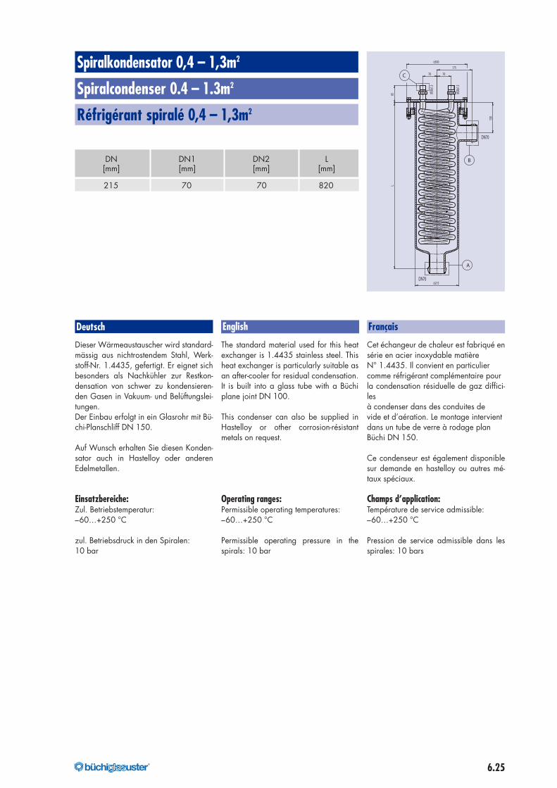
DN DN1 DN2 L[mm] [mm] [mm] [mm]
215 70 70 820
Spiralkondensator 0,4 – 1,3m2
Spiralcondenser 0.4 – 1.3m2
Réfrigérant spiralé 0,4 – 1,3m2
õ300
175
150
L
õ215
70 70
85
DN70
DN70
B
A
C
M30x
1.5
M30x
1.5
Deutsch FrançaisEnglish
Dieser Wärmeaustauscher wird standard-mässig aus nichtrostendem Stahl, Werk-stoff-Nr. 1.4435, gefertigt. Er eignet sichbesonders als Nachkühler zur Restkon-densation von schwer zu kondensieren-den Gasen in Vakuum- und Belüftungslei-tungen.Der Einbau erfolgt in ein Glasrohr mit Bü-chi-Planschliff DN 150.
Auf Wunsch erhalten Sie diesen Konden-sator auch in Hastelloy oder anderenEdelmetallen.
Einsatzbereiche:Zul. Betriebstemperatur:–60…+250 °C
zul. Betriebsdruck in den Spiralen:10 bar
The standard material used for this heatexchanger is 1.4435 stainless steel. Thisheat exchanger is particularly suitable asan after-cooler for residual condensation.It is built into a glass tube with a Büchiplane joint DN 100.
This condenser can also be supplied inHastelloy or other corrosion-résistantmetals on request.
Operating ranges:Permissible operating temperatures:–60…+250 °C
Permissible operating pressure in thespirals: 10 bar
Cet échangeur de chaleur est fabriqué ensérie en acier inoxydable matièreN° 1.4435. Il convient en particuliercomme réfrigérant complémentaire pourla condensation résiduelle de gaz diffici-lesà condenser dans des conduites devide et d’aération. Le montage intervientdans un tube de verre à rodage planBüchi DN 150.
Ce condenseur est également disponiblesur demande en hastelloy ou autres mé-taux spéciaux.
Champs d’application:Température de service admissible:–60…+250 °C
Pression de service admissible dans lesspirales: 10 bars
176040_buechi_Kapitel_6_Waermetauscher_mit Pantone_176040_buechi_Kapitel_6_Waermeaustauscher 07.07.17 07:12 Seite 25
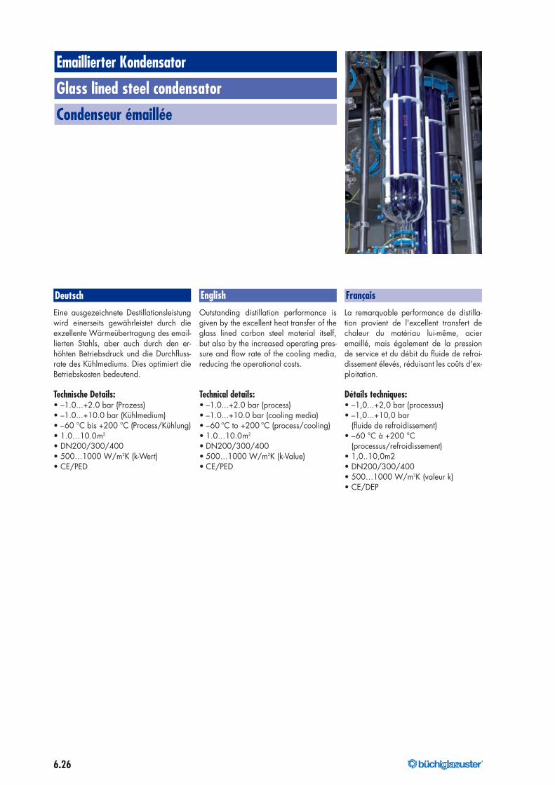
6.26 ®
Emaillierter Kondensator
Glass lined steel condensator
Condenseur émaillée
Deutsch FrançaisEnglish
Eine ausgezeichnete Destillationsleistungwird einerseits gewährleistet durch dieexzellente Wärmeübertragung des email-lierten Stahls, aber auch durch den er-höhten Betriebsdruck und die Durchfluss-rate des Kühlmediums. Dies optimiert dieBetriebskosten bedeutend.
Technische Details:• –1.0...+2.0 bar (Prozess)• –1.0...+10.0 bar (Kühlmedium)• –60 °C bis +200 °C (Process/Kühlung)• 1.0…10.0m2
• DN200/300/400• 500…1000 W/m2K (k-Wert)• CE/PED
Outstanding distillation performance isgiven by the excellent heat transfer of theglass lined carbon steel material itself,but also by the increased operating pres-sure and flow rate of the cooling media,reducing the operational costs.
Technical details:• –1.0...+2.0 bar (process)• –1.0...+10.0 bar (cooling media)• –60 °C to +200 °C (process/cooling)• 1.0…10.0m2
• DN200/300/400• 500…1000 W/m2K (k-Value)• CE/PED
La remarquable performance de distilla-tion provient de l'excellent transfert dechaleur du matériau lui-même, acieremaillé, mais également de la pressionde service et du débit du fluide de refroi-dissement élevés, réduisant les coûts d'ex-ploitation.
Détails techniques:• –1,0...+2,0 bar (processus)• –1,0...+10,0 bar
(fluide de refroidissement)• –60 °C à +200 °C
(processus/refroidissement)• 1,0..10,0m2• DN200/300/400• 500…1000 W/m2K (valeur k)• CE/DEP
176040_buechi_Kapitel_6_Waermetauscher_mit Pantone_176040_buechi_Kapitel_6_Waermeaustauscher 07.07.17 07:12 Seite 26
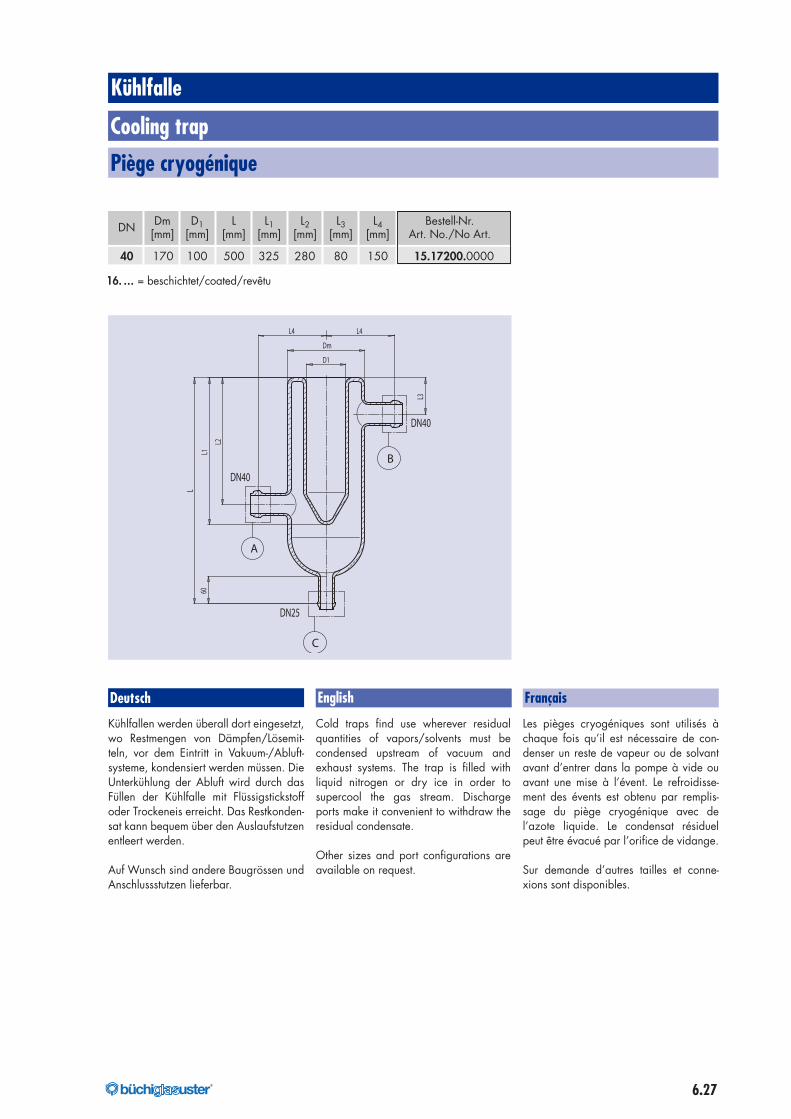
6.27®
L
L3
L1
L2
60
L4 L4
Dm
D1
DN40
DN40
DN25
A
B
C
Kühlfalle
Cooling trap
Piège cryogénique
Deutsch FrançaisEnglish
Kühlfallen werden überall dort eingesetzt,wo Restmengen von Dämpfen/Lösemit-teln, vor dem Eintritt in Vakuum-/Abluft-systeme, kondensiert werden müssen. DieUnterkühlung der Abluft wird durch dasFüllen der Kühlfalle mit Flüssigstickstoffoder Trockeneis erreicht. Das Restkonden-sat kann bequem über den Auslaufstutzenentleert werden.
Auf Wunsch sind andere Baugrössen undAnschlussstutzen lieferbar.
Cold traps find use wherever residualquantities of vapors/solvents must becondensed upstream of vacuum andexhaust systems. The trap is filled withliquid nitrogen or dry ice in order tosupercool the gas stream. Dischargeports make it convenient to withdraw theresidual condensate.
Other sizes and port configurations areavailable on request.
Les pièges cryogéniques sont utilisés àchaque fois qu’il est nécessaire de con-denser un reste de vapeur ou de solvantavant d’entrer dans la pompe à vide ouavant une mise à l’évent. Le refroidisse-ment des évents est obtenu par remplis-sage du piège cryogénique avec del’azote liquide. Le condensat résiduelpeut être évacué par l’orifice de vidange.
Sur demande d’autres tailles et conne-xions sont disponibles.
DN Dm D1 L L1 L2 L3 L4 Bestell-Nr.[mm] [mm] [mm] [mm] [mm] [mm] [mm] Art. No./No Art.
40 170 100 500 325 280 80 150 15.17200.0000
16. … = beschichtet/coated/revêtu
176040_buechi_Kapitel_6_Waermetauscher_mit Pantone_176040_buechi_Kapitel_6_Waermeaustauscher 07.07.17 07:12 Seite 27
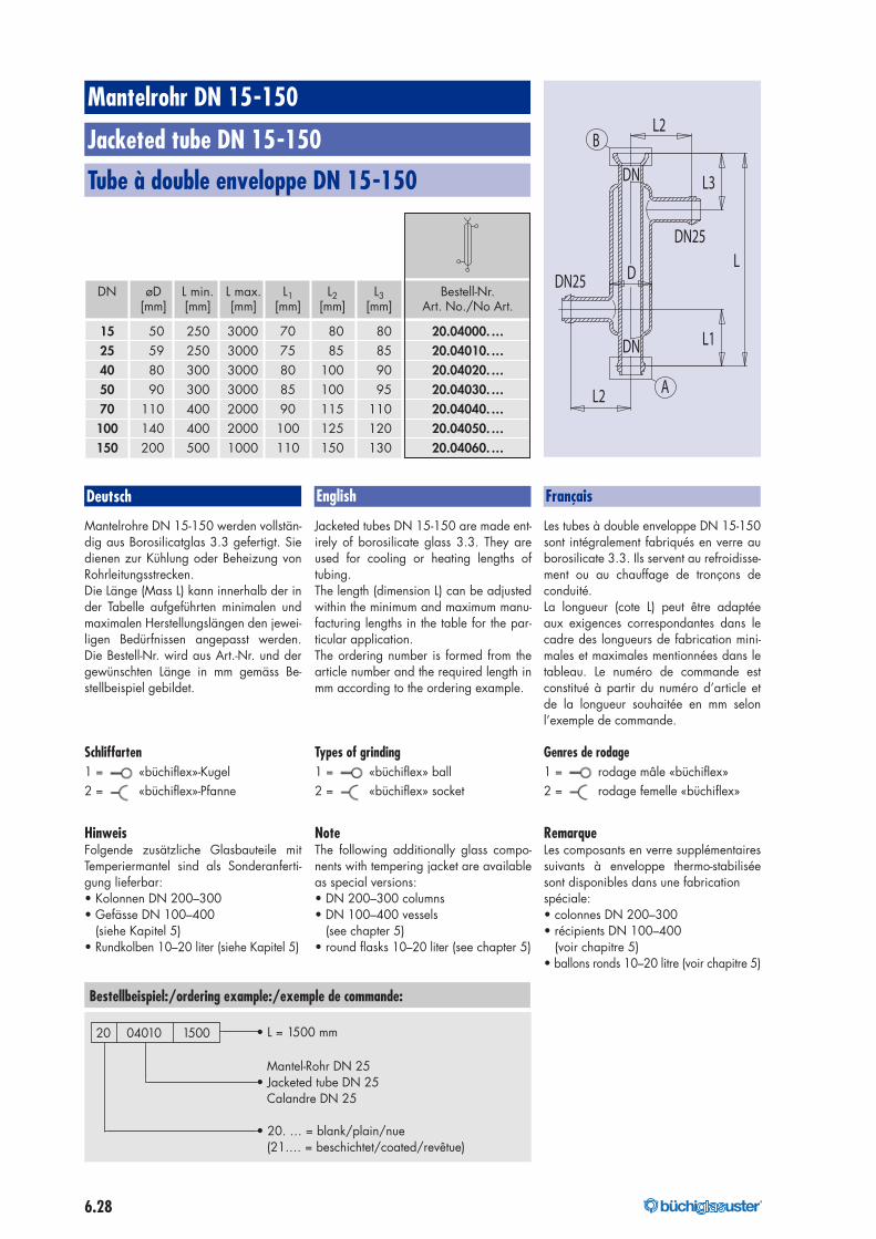
6.28 ®
Mantelrohr DN 15-150
Jacketed tube DN 15-150
Tube à double enveloppe DN 15-150
DN øD L min. L max. L1 L2 L3 Bestell-Nr.[mm] [mm] [mm] [mm] [mm] [mm] Art. No./No Art.
15 50 250 3000 70 80 80 20.04000.…25 59 250 3000 75 85 85 20.04010.…40 80 300 3000 80 100 90 20.04020.…50 90 300 3000 85 100 95 20.04030.…70 110 400 2000 90 115 110 20.04040.…
100 140 400 2000 100 125 120 20.04050.…150 200 500 1000 110 150 130 20.04060.…
Bestellbeispiel:/ordering example:/exemple de commande:
• L = 1500 mm
Mantel-Rohr DN 25• Jacketed tube DN 25
Calandre DN 25
• 20. … = blank/plain/nue(21.… = beschichtet/coated/revêtue)
20 04010 1500
Deutsch FrançaisEnglish
Mantelrohre DN 15-150 werden vollstän-dig aus Borosilicatglas 3.3 gefertigt. Siedienen zur Kühlung oder Beheizung vonRohrleitungsstrecken.Die Länge (Mass L) kann innerhalb der inder Tabelle aufgeführten minimalen undmaximalen Herstellungslängen den jewei-ligen Bedürfnissen angepasst werden.Die Bestell-Nr. wird aus Art.-Nr. und dergewünschten Länge in mm gemäss Be-stellbeispiel gebildet.
Schliffarten1 = «büchiflex»-Kugel2 = «büchiflex»-Pfanne
HinweisFolgende zusätzliche Glasbauteile mitTemperiermantel sind als Sonderanferti-gung lieferbar:• Kolonnen DN 200–300• Gefässe DN 100–400
(siehe Kapitel 5)• Rundkolben 10–20 liter (siehe Kapitel 5)
Jacketed tubes DN 15-150 are made ent-irely of borosilicate glass 3.3. They areused for cooling or heating lengths oftubing.The length (dimension L) can be adjustedwithin the minimum and maximum manu-facturing lengths in the table for the par-ticular application.The ordering number is formed from thearticle number and the required length inmm according to the ordering example.
Types of grinding1 = «büchiflex» ball2 = «büchiflex» socket
NoteThe following additionally glass compo-nents with tempering jacket are availableas special versions:• DN 200–300 columns• DN 100–400 vessels
(see chapter 5)• round flasks 10–20 liter (see chapter 5)
Les tubes à double enveloppe DN 15-150sont intégralement fabriqués en verre auborosilicate 3.3. Ils servent au refroidisse-ment ou au chauffage de tronçons deconduité.La longueur (cote L) peut être adaptéeaux exigences correspondantes dans lecadre des longueurs de fabrication mini-males et maximales mentionnées dans letableau. Le numéro de commande estconstitué à partir du numéro d’article etde la longueur souhaitée en mm selonl’exemple de commande.
Genres de rodage1 = rodage mâle «büchiflex»2 = rodage femelle «büchiflex»
RemarqueLes composants en verre supplémentairessuivants à enveloppe thermo-stabiliséesont disponibles dans une fabricationspéciale:• colonnes DN 200–300• récipients DN 100–400
(voir chapitre 5)• ballons ronds 10–20 litre (voir chapitre 5)
B
A
DN25
DN25
DN
DN
L2
L2
L
L3
D
L1
176040_buechi_Kapitel_6_Waermetauscher_mit Pantone_176040_buechi_Kapitel_6_Waermeaustauscher 07.07.17 07:12 Seite 28
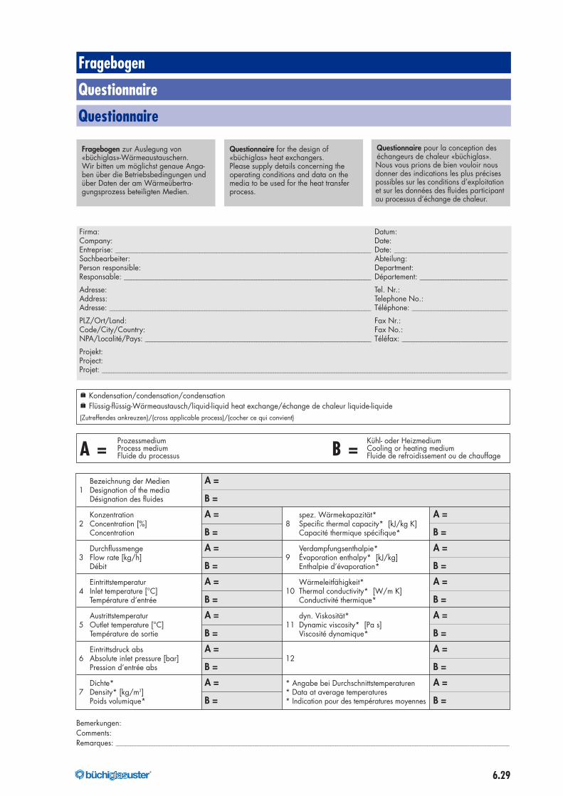
6.29®
Fragebogen
Questionnaire
Questionnaire
Fragebogen zur Auslegung von«büchiglas»-Wärmeaustauschern.Wir bitten um möglichst genaue Anga-ben über die Betriebsbedingungen undüber Daten der am Wärmeübertra-gungsprozess beteiligten Medien.
Questionnaire for the design of«büchiglas» heat exchangers.Please supply details concerning theoperating conditions and data on themedia to be used for the heat transferprocess.
Questionnaire pour la conception deséchangeurs de chaleur «büchiglas».Nous vous prions de bien vouloir nousdonner des indications les plus précisespossibles sur les conditions d’exploitationet sur les données des fluides participantau processus d’échange de chaleur.
Firma: Datum:Company: Date:Entreprise: __________________________________________________________________________________________________________ Date: _______________________________________________Sachbearbeiter: Abteilung:Person responsible: Department:Responsable: ______________________________________________________________________________________________________ Département: _____________________________________
Adresse: Tel. Nr.:Address: Telephone No.:Adresse: _____________________________________________________________________________________________________________ Téléphone: ________________________________________
PLZ/Ort/Land: Fax Nr.:Code/City/Country: Fax No.:NPA/Localité/Pays: _______________________________________________________________________________________________ Téléfax: ____________________________________________
Projekt:Project:Projet: ____________________________________________________________________________________________________________________________________________________________________________
e Kondensation/condensation/condensatione Flüssig-flüssig-Wärmeaustausch/liquid-liquid heat exchange/échange de chaleur liquide-liquide(Zutreffendes ankreuzen)/(cross applicable process)/(cocher ce qui convient)
Prozessmedium Kühl- oder Heizmedium
A = Process medium B = Cooling or heating mediumFluide du processus Fluide de refroidissement ou de chauffage
Bezeichnung der Medien A =1 Designation of the media
Désignation des fluides B =
Konzentration A = spez. Wärmekapazität* A =2 Concentration [%] 8 Specific thermal capacity* [kJ/kg K]
Concentration B = Capacité thermique spécifique* B =
Durchflussmenge A = Verdampfungsenthalpie* A =3 Flow rate [kg/h] 9 Évaporation enthalpy* [kJ/kg]
Débit B = Enthalpie d’évaporation* B =
Eintrittstemperatur A = Wärmeleitfähigkeit* A =4 Inlet temperature [°C] 10 Thermal conductivity* [W/m K]
Température d’entrée B = Conductivité thermique* B =
Austrittstemperatur A = dyn. Viskosität* A =5 Outlet temperature [°C] 11 Dynamic viscosity* [Pa s]
Température de sortie B = Viscosité dynamique* B =
Eintrittsdruck abs A = A =6 Absolute inlet pressure [bar] 12
Pression d’entrée abs B = B =
Dichte* A = * Angabe bei Durchschnittstemperaturen A =7 Density* [kg/m3] * Data at average temperatures
Poids volumique* B = * Indication pour des températures moyennes B =
Bemerkungen:Comments:Remarques: ___________________________________________________________________________________________________________________________________________________________________
176040_buechi_Kapitel_6_Waermetauscher_mit Pantone_176040_buechi_Kapitel_6_Waermeaustauscher 07.07.17 07:12 Seite 29

40.9
P206
.A00
7/07
.17
®Büchi AG +41 44 905 51 11Gschwaderstrasse12 [email protected] Uster, Switzerland www.buchiglas.com
176040_buechi_Kapitel_6_Waermetauscher_mit Pantone_176040_buechi_Kapitel_6_Waermeaustauscher 07.07.17 07:12 Seite 30