Embed Size (px)
Citation preview
INSTALLATION MANUALR410A Split Series
INVERTER Models FTXS50FV1B FTKS50FV1BFTXS60FV1B FTKS60FV1BFTXS71FV1B FTKS71FV1BFTX50GV1BFTX60GV1BFTX71GV1BNON-INVERTER Models FTYN50FV1B FTN50FV1BFTYN60FV1B FTN60FV1B
English
Français
Nederlands
Español
Italiano
ΕλληνικÜ
Portugues
Рóссêий
Türkçe
Deutsch
Installation manualR410A Split series
InstallationsanleitungSplit-Baureihe R410A
Manuel d’installationSérie split R410A
MontagehandleidingR410A Split-systeem
Manual de instalaciónSerie Split R410A
Manuale d’installazioneSerie Multiambienti R410A
Εγχειρßδιο εγκατÜστασηòδιαιροýìενηò σειρÜò R410A
Manual de Instalação Série split R410A
Рóêоводство по монтажóСерия R410A с раздельной óстановêой
Montaj kýlavuzlarý R410A Split serisi
00_CV_3P190114-1C.fm Page 1 Tuesday, November 17, 2009 5:28 PM
Um
eda
Cen
ter
Bld
g., 2
-4-1
2, N
akaz
aki-N
ishi
,K
ita-k
u, O
saka
, 530
-832
3 Ja
pan
DA
IKIN
IND
US
TR
IES
, LT
D.
Low
Vol
tage
200
6/95
/EC
Ele
ctro
mag
netic
Com
patib
ility
200
4/10
8/E
C*
3SB64526-5F
Shi
nri S
ada
Man
ager
Qua
lity
Con
trol
Dep
artm
ent
25th
. of N
ov. 2
009
DA
IKIN
.TC
F.0
15 M
18/1
1-20
09
FT
KS
50F
V1B
, FT
KS
60F
V1B
, FT
KS
71F
V1B
,F
TX
S50
FV
1B, F
TX
S60
FV
1B, F
TX
S71
FV
1B,
FT
X50
GV
1B, F
TX
60G
V1B
, FT
X71
GV
1B,
FT
YN
50F
V1B
, FT
YN
60F
V1B
, FT
N50
FV
1B, F
TN
60F
V1B
KE
MA
Qu
alit
y B
.V.
7473
6-K
RQ
/EM
C97
-495
7
3SB64526-5F.fm Page 1 Saturday, November 28, 2009 11:31 AM
1 ■English
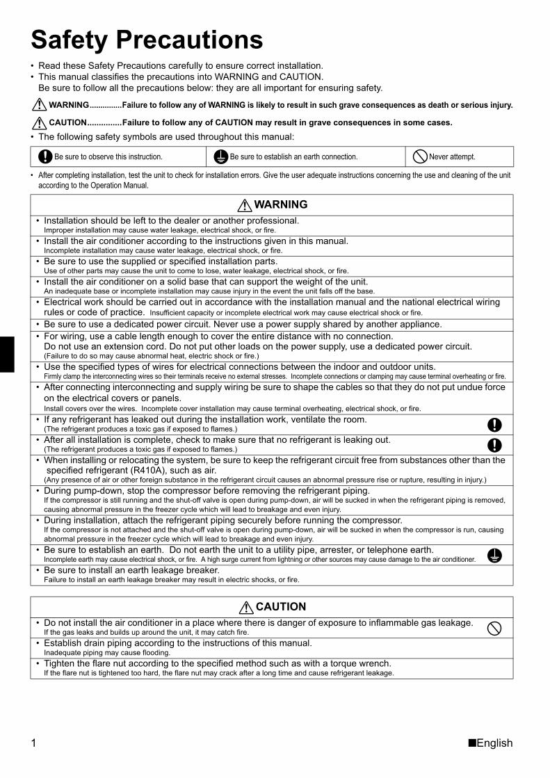
Safety Precautions• Read these Safety Precautions carefully to ensure correct installation.• This manual classifies the precautions into WARNING and CAUTION.
Be sure to follow all the precautions below: they are all important for ensuring safety.
WARNING...............Failure to follow any of WARNING is likely to result in such grave consequences as death or serious injury.
CAUTION...............Failure to follow any of CAUTION may result in grave consequences in some cases.• The following safety symbols are used throughout this manual:
• After completing installation, test the unit to check for installation errors. Give the user adequate instructions concerning the use and cleaning of the unit according to the Operation Manual.
Be sure to observe this instruction. Be sure to establish an earth connection. Never attempt.
WARNING• Installation should be left to the dealer or another professional.
Improper installation may cause water leakage, electrical shock, or fire.• Install the air conditioner according to the instructions given in this manual.
Incomplete installation may cause water leakage, electrical shock, or fire.• Be sure to use the supplied or specified installation parts.
Use of other parts may cause the unit to come to lose, water leakage, electrical shock, or fire.• Install the air conditioner on a solid base that can support the weight of the unit.
An inadequate base or incomplete installation may cause injury in the event the unit falls off the base.• Electrical work should be carried out in accordance with the installation manual and the national electrical wiring
rules or code of practice. Insufficient capacity or incomplete electrical work may cause electrical shock or fire.• Be sure to use a dedicated power circuit. Never use a power supply shared by another appliance.• For wiring, use a cable length enough to cover the entire distance with no connection.
Do not use an extension cord. Do not put other loads on the power supply, use a dedicated power circuit.(Failure to do so may cause abnormal heat, electric shock or fire.)
• Use the specified types of wires for electrical connections between the indoor and outdoor units.Firmly clamp the interconnecting wires so their terminals receive no external stresses. Incomplete connections or clamping may cause terminal overheating or fire.
• After connecting interconnecting and supply wiring be sure to shape the cables so that they do not put undue force on the electrical covers or panels.Install covers over the wires. Incomplete cover installation may cause terminal overheating, electrical shock, or fire.
• If any refrigerant has leaked out during the installation work, ventilate the room.(The refrigerant produces a toxic gas if exposed to flames.)
• After all installation is complete, check to make sure that no refrigerant is leaking out.(The refrigerant produces a toxic gas if exposed to flames.)
• When installing or relocating the system, be sure to keep the refrigerant circuit free from substances other than the specified refrigerant (R410A), such as air.
(Any presence of air or other foreign substance in the refrigerant circuit causes an abnormal pressure rise or rupture, resulting in injury.)• During pump-down, stop the compressor before removing the refrigerant piping.
If the compressor is still running and the shut-off valve is open during pump-down, air will be sucked in when the refrigerant piping is removed, causing abnormal pressure in the freezer cycle which will lead to breakage and even injury.
• During installation, attach the refrigerant piping securely before running the compressor.If the compressor is not attached and the shut-off valve is open during pump-down, air will be sucked in when the compressor is run, causing abnormal pressure in the freezer cycle which will lead to breakage and even injury.
• Be sure to establish an earth. Do not earth the unit to a utility pipe, arrester, or telephone earth.Incomplete earth may cause electrical shock, or fire. A high surge current from lightning or other sources may cause damage to the air conditioner.
• Be sure to install an earth leakage breaker.Failure to install an earth leakage breaker may result in electric shocks, or fire.
CAUTION• Do not install the air conditioner in a place where there is danger of exposure to inflammable gas leakage.
If the gas leaks and builds up around the unit, it may catch fire.• Establish drain piping according to the instructions of this manual.
Inadequate piping may cause flooding.• Tighten the flare nut according to the specified method such as with a torque wrench.
If the flare nut is tightened too hard, the flare nut may crack after a long time and cause refrigerant leakage.
01_EN_3P190114-1C.fm Page 1 Tuesday, December 1, 2009 4:43 PM
■English 2
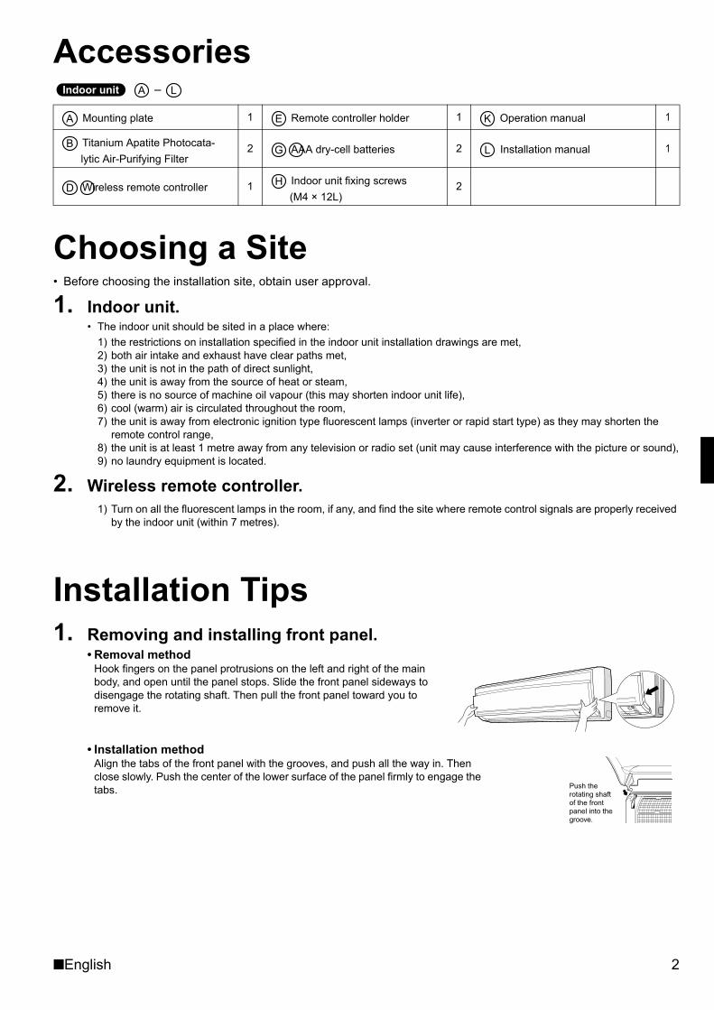
Accessories –
Choosing a Site• Before choosing the installation site, obtain user approval.
1. Indoor unit.• The indoor unit should be sited in a place where:
1) the restrictions on installation specified in the indoor unit installation drawings are met,2) both air intake and exhaust have clear paths met,3) the unit is not in the path of direct sunlight,4) the unit is away from the source of heat or steam,5) there is no source of machine oil vapour (this may shorten indoor unit life),6) cool (warm) air is circulated throughout the room,7) the unit is away from electronic ignition type fluorescent lamps (inverter or rapid start type) as they may shorten the
remote control range,8) the unit is at least 1 metre away from any television or radio set (unit may cause interference with the picture or sound),9) no laundry equipment is located.
2. Wireless remote controller.1) Turn on all the fluorescent lamps in the room, if any, and find the site where remote control signals are properly received
by the indoor unit (within 7 metres).
Installation Tips1. Removing and installing front panel.
• Removal methodHook fingers on the panel protrusions on the left and right of the main body, and open until the panel stops. Slide the front panel sideways to disengage the rotating shaft. Then pull the front panel toward you to remove it.
• Installation methodAlign the tabs of the front panel with the grooves, and push all the way in. Then close slowly. Push the center of the lower surface of the panel firmly to engage the tabs.
Mounting plate 1 Remote controller holder 1 Operation manual 1
Titanium Apatite Photocata-lytic Air-Purifying Filter
2 AAA dry-cell batteries 2 Installation manual 1
Wireless remote controller 1 Indoor unit fixing screws (M4 × 12L)
2
������ ���� � �
� � �
�� �
��
Push the rotating shaft of the front panel into the groove.
01_EN_3P190114-1C.fm Page 2 Tuesday, December 1, 2009 4:43 PM
3 ■English
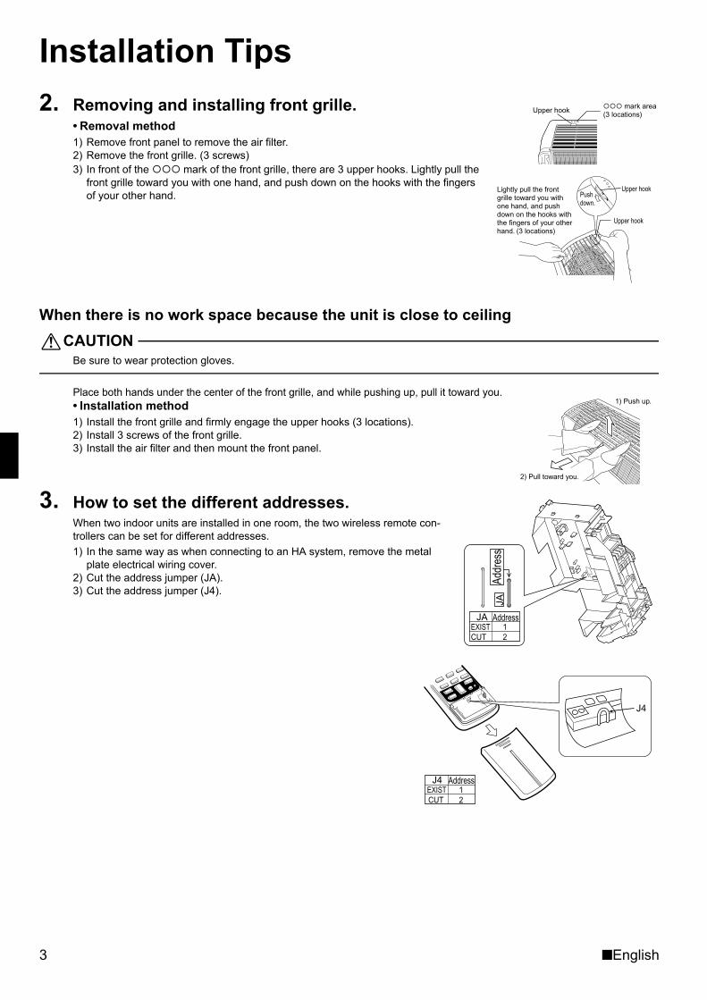
Installation Tips2. Removing and installing front grille.
• Removal method1) Remove front panel to remove the air filter.2) Remove the front grille. (3 screws)3) In front of the mark of the front grille, there are 3 upper hooks. Lightly pull the
front grille toward you with one hand, and push down on the hooks with the fingers of your other hand.
When there is no work space because the unit is close to ceilingCAUTION
Be sure to wear protection gloves.
Place both hands under the center of the front grille, and while pushing up, pull it toward you.• Installation method1) Install the front grille and firmly engage the upper hooks (3 locations).2) Install 3 screws of the front grille.3) Install the air filter and then mount the front panel.
3. How to set the different addresses.When two indoor units are installed in one room, the two wireless remote con-trollers can be set for different addresses.1) In the same way as when connecting to an HA system, remove the metal
plate electrical wiring cover.2) Cut the address jumper (JA).3) Cut the address jumper (J4).
��� mark area (3 locations)
Upper hook
Lightly pull the front grille toward you with one hand, and push down on the hooks with the fingers of your other hand. (3 locations)
Pushdown.
Upper hook
Upper hook
1) Push up.
2) Pull toward you.
Addr
ess
JA
AddressJAEXIST 1CUT 2
AddressJ4EXIST 1 CUT 2
J4
01_EN_3P190114-1C.fm Page 3 Tuesday, December 1, 2009 4:43 PM
■English 4
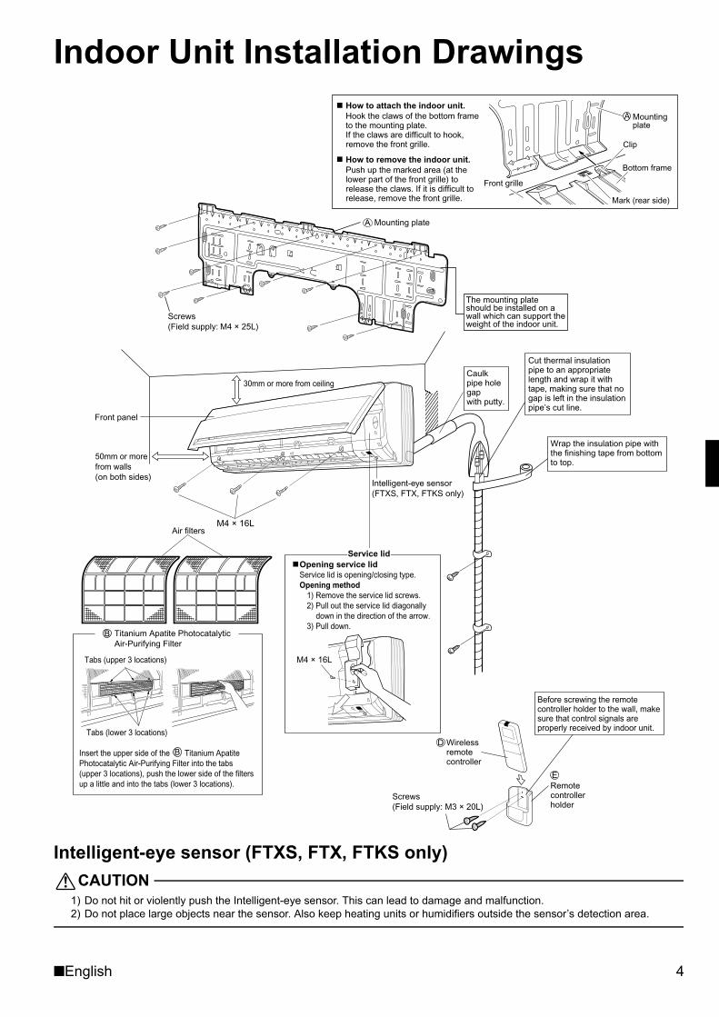
Indoor Unit Installation Drawings
Intelligent-eye sensor (FTXS, FTX, FTKS only)CAUTION
1) Do not hit or violently push the Intelligent-eye sensor. This can lead to damage and malfunction.2) Do not place large objects near the sensor. Also keep heating units or humidifiers outside the sensor’s detection area.
M4 × 16L
M4 × 16L
30mm or more from ceiling
Front panel
50mm or more from walls (on both sides)
Intelligent-eye sensor(FTXS, FTX, FTKS only)
Service lidOpening service lidService lid is opening/closing type.Opening method
1) Remove the service lid screws.2) Pull out the service lid diagonally
down in the direction of the arrow.3) Pull down.
Wrap the insulation pipe with the finishing tape from bottom to top.
Cut thermal insulation pipe to an appropriate length and wrap it with tape, making sure that no gap is left in the insulation pipe’s cut line.
Caulk pipe hole gap with putty.
The mounting plate should be installed on a wall which can support the weight of the indoor unit.
D
ERemote controller holder
Wireless remote controller
Before screwing the remote controller holder to the wall, make sure that control signals are properly received by indoor unit.
B Titanium Apatite Photocatalytic Air-Purifying Filter
Tabs (upper 3 locations)
Tabs (lower 3 locations)
Air filters
Insert the upper side of the Titanium Apatite Photocatalytic Air-Purifying Filter into the tabs (upper 3 locations), push the lower side of the filters up a little and into the tabs (lower 3 locations).
B
How to attach the indoor unit.Hook the claws of the bottom frameto the mounting plate.If the claws are difficult to hook,remove the front grille.
How to remove the indoor unit.Push up the marked area (at thelower part of the front grille) torelease the claws. If it is difficult torelease, remove the front grille.
Front grille
A Mountingplate
Clip
Bottom frame
Mark (rear side)
Screws (Field supply: M4 × 25L)
A Mounting plate
Screws (Field supply: M3 × 20L)
01_EN_3P190114-1C.fm Page 4 Tuesday, December 1, 2009 4:43 PM
5 ■English
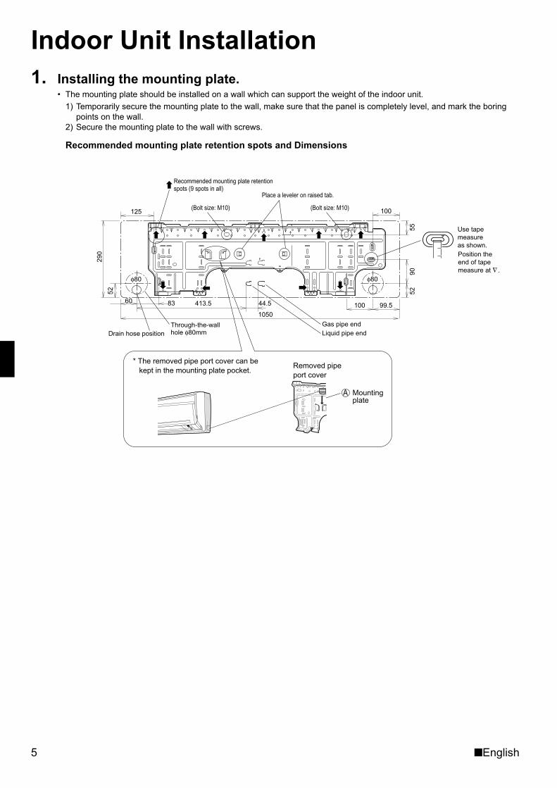
Indoor Unit Installation1. Installing the mounting plate.
• The mounting plate should be installed on a wall which can support the weight of the indoor unit.1) Temporarily secure the mounting plate to the wall, make sure that the panel is completely level, and mark the boring
points on the wall.2) Secure the mounting plate to the wall with screws.
Recommended mounting plate retention spots and Dimensions
125
60 83 413.5 44.5
290
52
105099.5
5290
55
100
100
Through-the-wall hole φ80mmDrain hose position
φ80 φ80
Recommended mounting plate retention spots (9 spots in all)
(Bolt size: M10) (Bolt size: M10)
Place a leveler on raised tab.
Use tape measure as shown.Position the end of tape measure at ∇ .
Gas pipe end Liquid pipe end
* The removed pipe port cover can be kept in the mounting plate pocket.
Removed pipe port cover
A Mounting plate
01_EN_3P190114-1C.fm Page 5 Tuesday, December 1, 2009 4:43 PM
■English 6
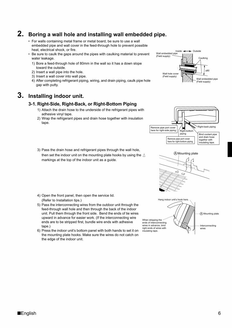
2. Boring a wall hole and installing wall embedded pipe.• For walls containing metal frame or metal board, be sure to use a wall
embedded pipe and wall cover in the feed-through hole to prevent possible heat, electrical shock, or fire.
• Be sure to caulk the gaps around the pipes with caulking material to prevent water leakage.1) Bore a feed-through hole of 80mm in the wall so it has a down slope
toward the outside.2) Insert a wall pipe into the hole.3) Insert a wall cover into wall pipe.4) After completing refrigerant piping, wiring, and drain piping, caulk pipe hole
gap with putty.
3. Installing indoor unit.3-1. Right-Side, Right-Back, or Right-Bottom Piping
1) Attach the drain hose to the underside of the refrigerant pipes with adhesive vinyl tape.
2) Wrap the refrigerant pipes and drain hose together with insulation tape.
3) Pass the drain hose and refrigerant pipes through the wall hole, then set the indoor unit on the mounting plate hooks by using the markings at the top of the indoor unit as a guide.
4) Open the front panel, then open the service lid. (Refer to Installation tips.)
5) Pass the interconnecting wires from the outdoor unit through the feed-through wall hole and then through the back of the indoor unit. Pull them through the front side. Bend the ends of tie wires upward in advance for easier work. (If the interconnecting wire ends are to be stripped first, bundle wire ends with adhesive tape.)
6) Press the indoor unit’s bottom panel with both hands to set it on the mounting plate hooks. Make sure the wires do not catch on the edge of the indoor unit.
Inside Outside
Caulking
Wall embedded pipe (Field supply)
Wall hole cover(Field supply)
Wall embedded pipe (Field supply)
φ80
Right-bottom piping
Right-back piping
Bind coolant pipe and drain hose together with insulating tape.
Remove pipe port cover here for right-side piping
Remove pipe port cover here for right-bottom piping
Mounting plateA
When stripping the ends of interconnecting wires in advance, bind right ends of wires with insulating tape.
Hang indoor unit’s hook here.
Interconnectingwires
Mounting plateA
01_EN_3P190114-1C.fm Page 6 Tuesday, December 1, 2009 4:43 PM
7 ■English
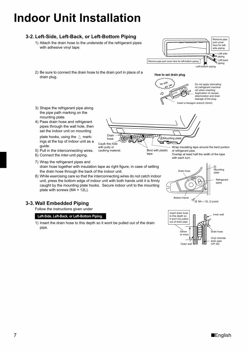
Indoor Unit Installation3-2. Left-Side, Left-Back, or Left-Bottom Piping
1) Attach the drain hose to the underside of the refrigerant pipes with adhesive vinyl tape.
2) Be sure to connect the drain hose to the drain port in place of a drain plug.
3) Shape the refrigerant pipe along the pipe path marking on the mounting plate.
4) Pass drain hose and refrigerant pipes through the wall hole, then set the indoor unit on mounting plate hooks, using the mark-ings at the top of indoor unit as a guide.
5) Pull in the interconnecting wires.6) Connect the inter-unit piping.
7) Wrap the refrigerant pipes and drain hose together with insulation tape as right figure, in case of setting the drain hose through the back of the indoor unit.
8) While exercising care so that the interconnecting wires do not catch indoor unit, press the bottom edge of indoor unit with both hands until it is firmly caught by the mounting plate hooks. Secure indoor unit to the mounting plate with screws (M4 × 12L).
3-3. Wall Embedded PipingFollow the instructions given under
1) Insert the drain hose to this depth so it wont be pulled out of the drain pipe.
Left-Side, Left-Back, or Left-Bottom Piping.
Remove pipe port cover here for left-bottom piping
Remove pipe port cover here for left-side piping
Left-bottom piping
Left-side piping
Left-back piping
How to set drain plug
No gapDo not apply lubricating oil (refrigerant machine oil) when inserting.Application of causes deterioration and drain leakage of the plug.
Insert a hexagon wrench (4mm)
Wrap insulating tape around the bent portion of refrigerant pipe. Overlap at least half the width of the tape with each turn.
Drain hose
Caulk this hole with putty or caulking material. Bind with plastic
tape.
A Mounting plate
Refrigerantpipes
Drain hose
Bottom frame
H M4 × 12L (2 point)
Mountingplate
A
Inner wall
Vinyl chloride drain pipe (VP-30)
Drain hose50mm or more
Insert drain hose to this depth so it won’t be pulled out of drain pipe.
Outer wall
01_EN_3P190114-1C.fm Page 7 Tuesday, December 1, 2009 4:43 PM
■English 8
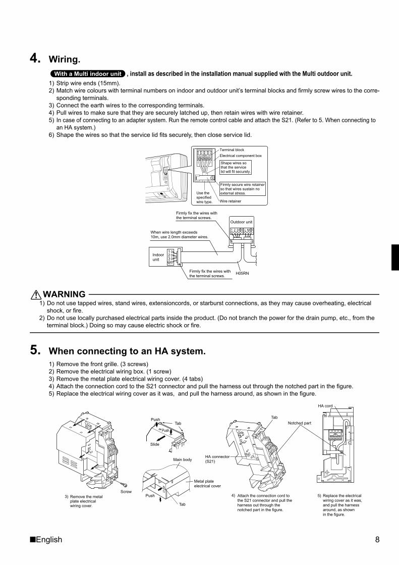
4. Wiring., install as described in the installation manual supplied with the Multi outdoor unit.
1) Strip wire ends (15mm).2) Match wire colours with terminal numbers on indoor and outdoor unit’s terminal blocks and firmly screw wires to the corre-
sponding terminals.3) Connect the earth wires to the corresponding terminals.4) Pull wires to make sure that they are securely latched up, then retain wires with wire retainer.5) In case of connecting to an adapter system. Run the remote control cable and attach the S21. (Refer to 5. When connecting to
an HA system.)6) Shape the wires so that the service lid fits securely, then close service lid.
WARNING1) Do not use tapped wires, stand wires, extensioncords, or starburst connections, as they may cause overheating, electrical
shock, or fire.2) Do not use locally purchased electrical parts inside the product. (Do not branch the power for the drain pump, etc., from the
terminal block.) Doing so may cause electric shock or fire.
5. When connecting to an HA system.1) Remove the front grille. (3 screws)2) Remove the electrical wiring box. (1 screw)3) Remove the metal plate electrical wiring cover. (4 tabs)4) Attach the connection cord to the S21 connector and pull the harness out through the notched part in the figure.5) Replace the electrical wiring cover as it was, and pull the harness around, as shown in the figure.
���� � ����� ���� ���
Shape wires so that the service lid will fit securely.
Terminal block
Electrical component box
Wire retainer
Firmly secure wire retainer so that wires sustain no external stress.Use the
specified wire type.
123
1 2 3 L NWhen wire length exceeds 10m, use 2.0mm diameter wires.
H05RN
Firmly fix the wires with the terminal screws.
Outdoor unit
Indoor unit
Firmly fix the wires with the terminal screws.
Screw
HA cord
HA connector(S21)
Tab
TabPush
Slide
Push
Metal plate electrical cover
Tab
Push
Main body
Notched part
4) 5) Replace the electrical wiring cover as it was, and pull the harness around, as shown in the figure.
Attach the connection cord to the S21 connector and pull the harness out through the notched part in the figure.
3) Remove the metal plate electrical wiring cover.
01_EN_3P190114-1C.fm Page 8 Tuesday, December 1, 2009 4:43 PM
9 ■English
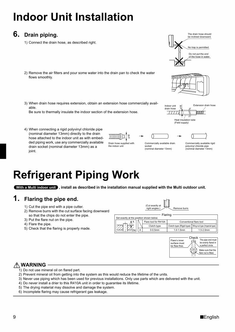
Indoor Unit Installation6. Drain piping.
1) Connect the drain hose, as described right.
2) Remove the air filters and pour some water into the drain pan to check the water flows smoothly.
3) When drain hose requires extension, obtain an extension hose commercially avail-able. Be sure to thermally insulate the indoor section of the extension hose.
4) When connecting a rigid polyvinyl chloride pipe (nominal diameter 13mm) directly to the drain hose attached to the indoor unit as with embed-ded piping work, use any commercially available drain socket (nominal diameter 13mm) as a joint.
Refrigerant Piping Work, install as described in the installation manual supplied with the Multi outdoor unit.
1. Flaring the pipe end.1) Cut the pipe end with a pipe cutter.2) Remove burrs with the cut surface facing downward
so that the chips do not enter the pipe.3) Put the flare nut on the pipe.4) Flare the pipe.5) Check that the flaring is properly made.
WARNING1) Do not use mineral oil on flared part.2) Prevent mineral oil from getting into the system as this would reduce the lifetime of the units.3) Never use piping which has been used for previous installations. Only use parts which are delivered with the unit.4) Do never install a drier to this R410A unit in order to guarantee its lifetime.5) The drying material may dissolve and damage the system.6) Incomplete flaring may cause refrigerant gas leakage.
The drain hose should be inclined downward.
No trap is permitted.
Do not put the end of the hose in water.
Indoor unit drain hose φ1
8 Extension drain hose
Heat insulation tube(Field supply)
Drain hose supplied with the indoor unit
Commercially available drain socket (nominal diameter 13mm)
Commercially available rigid polyvinyl chloride pipe(nominal diameter 13mm)
φ18
���� � ����� ���� ���
Set exactly at the position shown below.
A
Flaring
Die A 0-0.5mm
Clutch-type
Flare tool for R410A
1.0-1.5mm
Clutch-type (Rigid-type)
1.5-2.0mm
Wing-nut type (Imperial-type)
Conventional flare tool
(Cut exactly at right angles.) Remove burrs
CheckFlare’s inner surface must be flaw-free.
The pipe end must be evenly flared in a perfect circle.
Make sure that the flare nut is fitted.
01_EN_3P190114-1C.fm Page 9 Tuesday, December 1, 2009 4:43 PM
■English 10
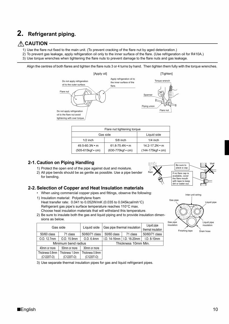
2. Refrigerant piping.CAUTION
1) Use the flare nut fixed to the main unit. (To prevent cracking of the flare nut by aged deterioration.)2) To prevent gas leakage, apply refrigeration oil only to the inner surface of the flare. (Use refrigeration oil for R410A.)3) Use torque wrenches when tightening the flare nuts to prevent damage to the flare nuts and gas leakage.
Align the centres of both flares and tighten the flare nuts 3 or 4 turns by hand. Then tighten them fully with the torque wrenches.
2-1. Caution on Piping Handling1) Protect the open end of the pipe against dust and moisture.2) All pipe bends should be as gentle as possible. Use a pipe bender
for bending.
2-2. Selection of Copper and Heat Insulation materials• When using commercial copper pipes and fittings, observe the following:1) Insulation material: Polyethylene foam
Heat transfer rate: 0.041 to 0.052W/mK (0.035 to 0.045kcal/mh°C)Refrigerant gas pipe’s surface temperature reaches 110°C max.Choose heat insulation materials that will withstand this temperature.
2) Be sure to insulate both the gas and liquid piping and to provide insulation dimen-sions as below.
3) Use separate thermal insulation pipes for gas and liquid refrigerant pipes.
Gas side Liquid side Gas pipe thermal insulation Liquid pipethermal insulation
50/60 class 71 class 50/60/71 class 50/60 class 71 class 50/60/71 classO.D. 12.7mm O.D. 15.9mm O.D. 6.4mm I.D. 14-16mm I.D. 16-20mm I.D. 8-10mm
Minimum bend radius Thickness 10mm Min.40mm or more 50mm or more 30mm or more
Thickness 0.8mm (C1220T-O)
Thickness 1.0mm (C1220T-O)
Thickness 0.8mm (C1220T-O)
Torque wrench
Piping union
Flare nut
Do not apply refrigeration
oil to the outer surface.
Flare nut
Apply refrigeration oil to
the inner surface of the
flare.
Do not apply refrigeration
oil to the flare nut avoid
tightening with over torque.
Spanner
[Apply oil] [Tighten]
Flare nut tightening torque
Gas side Liquid side
1/2 inch 5/8 inch 1/4 inch
49.5-60.3N � m 61.8-75.4N � m 14.2-17.2N � m
(505-615kgf � cm) (630-770kgf � cm) (144-175kgf � cm)
Valve cap tightening torque
Wall
If no flare cap is available, cover the flare mouth with tape to keep dirt or water out.
Be sure to place a cap.
Rain
Gas pipeLiquid pipe
Gas pipe insulation
Liquid pipe insulation
Finishing tape Drain hose
Inter-unit wiring
01_EN_3P190114-1C.fm Page 10 Tuesday, December 1, 2009 4:43 PM
11 ■English
Trial Operation and Testing1. Trial operation and testing.
1-1 Measure the supply voltage and make sure that it falls in the specified range.1-2 Trial operation should be carried out in either cooling or heating mode.
■ For Heat pump• In cooling mode, select the lowest programmable temperature; in heating mode, select the highest programmable temper-
ature.1) Trial operation may be disabled in either mode depending on the room temperature.
Use the remote controller for trial operation as described below.2) After trial operation is complete, set the temperature to a normal level (26°C to 28°C in cooling mode, 20°C to 24°C in
heating mode).3) For protection, the system disables restart operation for 3 minutes after it is turned off.
■ For Cooling only• Select the lowest programmable temperature.
1) Trial operation in cooling mode may be disabled depending on the room temperature.Use the remote controller for trial operation as described below.
2) After trial operation is complete, set the temperature to a normal level (26°C to 28°C).3) For protection, the unit disables restart operation for 3 minutes after it is turned off.
1-3 Carry out the test operation in accordance with the Operation Manual to ensure that all functions and parts, such as louver movement, are working properly.• The air conditioner requires a small amount of power in its standby mode. If the system is not to be used for some
time after installation, shut off the circuit breaker to eliminate unnecessary power consumption.• If the circuit breaker trips to shut off the power to the air conditioner, the system will restore the original operation
mode when the circuit breaker is opened again.
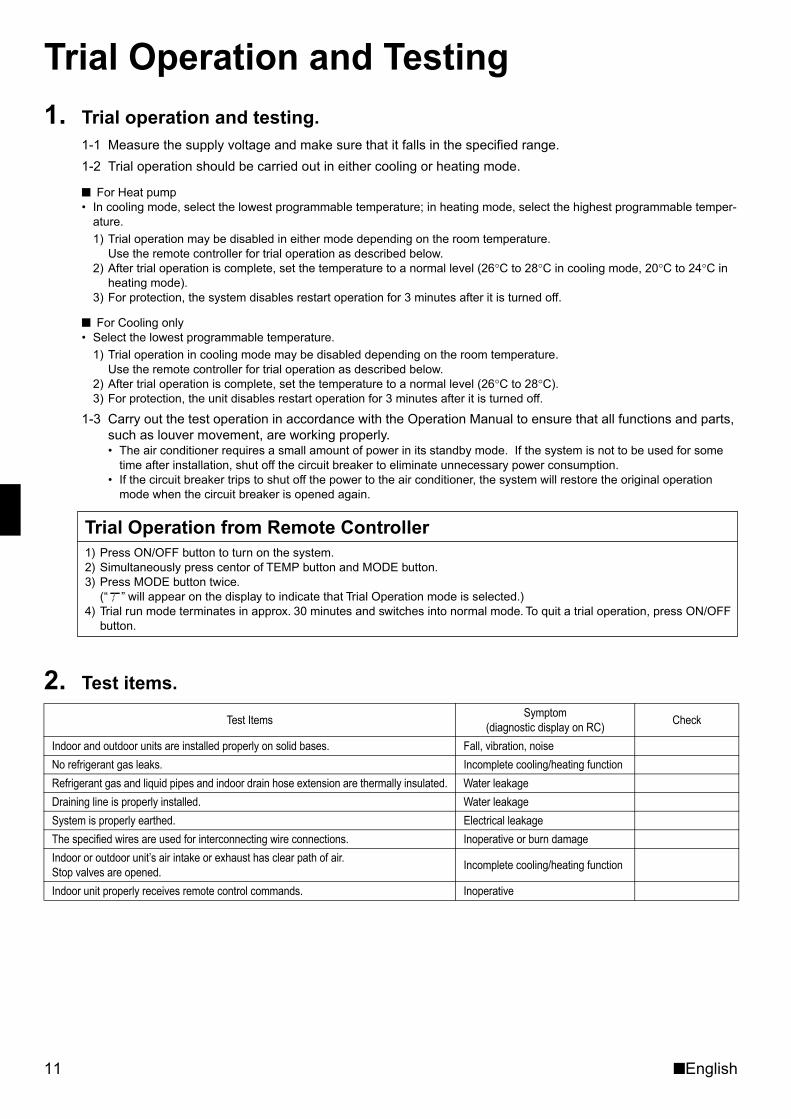
2. Test items.
Test Items Symptom(diagnostic display on RC) Check
Indoor and outdoor units are installed properly on solid bases. Fall, vibration, noiseNo refrigerant gas leaks. Incomplete cooling/heating functionRefrigerant gas and liquid pipes and indoor drain hose extension are thermally insulated. Water leakageDraining line is properly installed. Water leakageSystem is properly earthed. Electrical leakageThe specified wires are used for interconnecting wire connections. Inoperative or burn damageIndoor or outdoor unit’s air intake or exhaust has clear path of air.Stop valves are opened. Incomplete cooling/heating function
Indoor unit properly receives remote control commands. Inoperative
1) Press ON/OFF button to turn on the system.2) Simultaneously press centor of TEMP button and MODE button.3) Press MODE button twice.
(“ ” will appear on the display to indicate that Trial Operation mode is selected.)4) Trial run mode terminates in approx. 30 minutes and switches into normal mode. To quit a trial operation, press ON/OFF
button.
Trial Operation from Remote Controller
01_EN_3P190114-1C.fm Page 11 Tuesday, December 1, 2009 4:43 PM
(1002) HT3P190114-1C M06B094CTwo-dimensional bar code is a code for manufacturing.
00_CV_3P190114-1C.fm Page 2 Tuesday, November 17, 2009 5:28 PM