Embed Size (px)
DESCRIPTION
http://www.dungs.com/fileadmin/media/Downloads/DBs_BMAs/225913.pdf?1290007620
Citation preview
1 … 8
225
913
02.1
0
Betriebs- und Montagean-leitung
Gas- und Luftdruckwächter GW … A4, GW … A2Druckbegrenzer ÜB … A4, ÜB … A2NB … A4, NB … A2DoppeldruckwächterGW … / … A4
Operation and assembly instructions
Gas and air pressure switchGW … A4, GW … A2Pressure limiterÜB … A4, ÜB … A2NB … A4, NB … A2Double pressure switchGW … / … A4
Max. Betriebsdruck / Max. operating pressure/ GW, NB, ÜB 3/10/50/150 A4/A2 pmax. = 500 mbar (50 kPa)GW, NB, ÜB 500 A4/A2 pmax. = 600 mbar
Druckwächter/ Pressure Switch/
Typ/Type/GW…A2, NB…A2, ÜB…A2GW…A4, NB…A4, ÜB…A4nach / acc. / EN 1854
UmgebungstemperaturAmbient temperature
–15 °C … +70 °C
MediumstemperaturMedium temperature
–15 °C … +70 °C
LagertemperaturStorage temperature
–30 °C … +80 °C
Familie 1 + 2 + 3Family 1 + 2 + 3 1 + 2 + 3
Schutzart Degree of protection
IP 54 nach / acc. / IEC 529 (EN 60529)
~(AC) eff., min./mini 10 V, ~(AC) max. /maxi. 250 V=(DC) min./mini. 12 V, =(DC) max. /maxi. 48 V
EinstellbereicheSetting ranges
StandardeinbaulageStandard installation position
Bei waagerechtem Einbau schaltet der Druckwächter bei einem um ca. 0,5 mbar höheren Druck.In the horizontal installation position the switching pressure is increased by approx. 0.5 mbar.
Bei Einbau waagerecht über Kopf schaltet der Druckwächter bei einem um ca. 0,5 mbar niedrigerem Druck.When the pressure switch is mounted horizontally overhead, its switching pressure decreases by approx. 0.5 mbar.
Bei Einbau in einer Zwischeneinbaulage schaltet der Druckwächter bei einem vom eingestellten Sollwert maximal ± 0,5 mbar abweichenden Druck.When the pressure switch is mounted in an intermediate position, its switching pressure deviates by max. ± 0.5 mbar from the setpoint.
Einbaulage / Installation position / α
αα
α
Nennstrom/nominal current/ ~(AC) 10 ASchaltstrom/current on contact:~(AC) eff., min./mini 20 mA,~(AC) max./maxi. 6 A cos ϕ = 1~(AC) max./maxi. 3 A cos ϕ = 0,6 =(DC) min./mini. 20 mA=(DC) max./maxi. 1 A
[mbar]
EN 1854
2,5 – 50 mbar
0,4 – 3 mbar
100 – 500 mbar
30 – 150 mbar5 – 150 mbar
1 – 10 mbar
50 – 500 mbar
[ V ]
[A]EN 1854
Gas Gaz
°C
0
+80
-30
°C
0
+70
-15
IEC 529IEC 529
°C
0
+70
-15
2 … 8
225
913
02.1
0
G 1/4
7 Nm
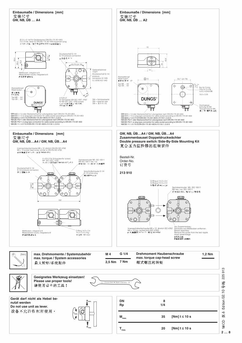
Einbaumaße / Dimensions [mm]
GW, NB, ÜB … A4
Einbaumaße / Dimensions [mm]
GW, NB, ÜB … A2
Einbaumaße / Dimensions [mm]
GW, NB, ÜB…A4 / GW, NB, ÜB…A4
GW, NB, ÜB…A4 / GW, NB, ÜB…A4Zusammenbauset Doppeldruckwächter Double pressure switch: Side-By-Side Mounting Kit
Bestell-Nr. Order-No.
213 910
1,2 NmM 4
2,5 Nm
DNRp
Mmax.
Tmax.
[Nm] t ≤ 10 s
[Nm] t ≤ 10 s
Gerät darf nicht als Hebel be-nutzt werdenDo not use unit as lever.
max. Drehmomente / Systemzubehörmax. torque / System accessories
Geeignetes Werkzeug einsetzen! Please use proper tools!
Drehmoment Haubenschraubemax. torque cap-head screw
21
23
81/4
35
20
[Nm]
18
19
Mmax.
Mmax.
Tmax.
59,4
38,4 10
,3
18,5
Made in Germany
M20 x 1,5 oder Steckanschluß für Leitungsdose nach DIN EN 175 301-803M20 x 1.5 or plug-type connection for cable socket according to DIN EN 175 301-803
Ø 2,5 x 9 tief für Gerätestecker DIN EN 175 301-8032.5 x 9 dia. deep for DIN EN 175 301-803 equipment plug
Meßstutzen, integriert ø 9Measurement nozzle, integrated ø 9
RückstellknopfReset button
Typ NB … A4Typ ÜB … A4
76
53,75 (LK 76)
72
SW21
4 X Ø 4,2für Schrauben M4 ISO 1207, 4762for M4 ISO 1207, 4762 screws
Druckanschluß G 1/4G 1/4 pressure connection
SW = SchlüsselweiteSW = spanner sizeSW = 扳手开口度
Optional/optional可选件
Druckanschluß G 1/4pressure connection G 1/4G 压力管接头G 1/4G
RückstellknopfReset button
Typ NB … A2Typ ÜB … A2
M20 x 1,5 oder Steckanschluß für Leitungsdose nach DIN EN 175 301-803M20 x 1.5 or plug-type connection for cable socket according to DIN EN 175 301-803
21
3
72
43,8
10
23
53,7 (LK 76)72
•
•
•
2 2
Durchgangs-bohrung für M4Through-hole for M4
Nur für O-ringOnly for O-ring 仅用于O型密封圈
10,5 x 2,25
152
�����
�����
SW
21
Meßstutzen, integriert ø 9Measurement nozzle, integrated ø 9
O-Ring 14,3 x 2,414.3 x 2.4 o ring
Sechskantmutter M5 ISO 10511M5 ISO 10511 hex. nut
Druckanschluß G 1/4G 1/4 pressure connection
4 x Ø 4,2 für Schrauben/for screwsM4 ISO 1207, 4762
Innensechskantschraube M5 x 12, ähnlich DIN EN ISO 4762M5 x 12 socket head screw, similar to DIN EN ISO 4762
Verschlußschraube G 1/4G 1/4 screw plug
G 1/4
G 1/4
O-Ring ø 14,3 x 2,4O-Ring ø 14.3 x 2.4
Sechskantmutter M5 ISO 10511M5 hex. nut, ISO 10511
Innensechskantschraube M5 x 12, ähnlich ISO 4762M5 x 12 hex. socket bolt (ISO 4762)
Vor Zusammenbau:Schraube aus Meßstutzen entfernen.Before assembly:Remove the screw from the test nipple.Avant assemblage
GW:M20 x 1.5或者根据DIN EN 175 301-803标准的触头盒插接GW:M20 x 1.5或者根据DIN EN 175 301-803标准的触头盒插接
GW:GW:
NB/ÜB: PG11 oder Steckanschluß für Leitungsdose nach DIN EN 175 301-803NB/ÜB: PG11 or plug-type connection for cable socket according to DIN EN 175 301-803NB/ÜB: PG11或者根据DIN EN 175 301-803标准的触头盒插接
GW:M20 x 1.5或者根据DIN EN 175 301-803标准的触头盒插接GW:M20 x 1.5或者根据DIN EN 175 301-803标准的触头盒插接
GW:GW:
NB/ÜB: PG11 oder Steckanschluß für Leitungsdose nach DIN EN 175 301-803NB/ÜB: PG11 or plug-type connection for cable socket according to DIN EN 175 301-803NB/ÜB: PG11或者根据DIN EN 175 301-803标准的触头盒插接
3 … 8
225
913
02.1
0
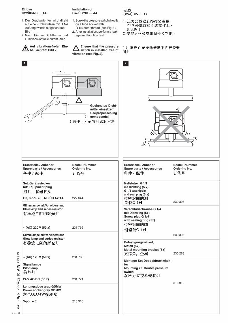
EinbauGW/ÜB/NB … A4
1. Der Druckwächter wird direkt auf einen Rohrstutzen mit R 1/4 Außengewinde aufgeschraubt.
Bild 1.2. Nach Einbau Dichtheits- und
Funktionskontrolle durchführen.
Auf vibrationsfreien Ein-bau achten! Bild 2.
Installation ofGW/ÜB/NB … A4
1. Screw the pressure switch directly on a tube socket with
R 1/4 outer thread (see Fig. 1).2. After installation, perform a leak-
age and function test.
Ensure that the pressure switch is installed free of
vibration (see Fig. 2).
Ersatzteile / ZubehörSpare parts / Accessories
Set: GerätesteckerKit: Equipment plug
G3, 3-pol. + E, NB/ÜB A2/A4
Glimmlampe mit VorwiderstandGlow lamp and series resistor
~ (AC) 220 V (50 x)
Glimmlampe mit VorwiderstandGlow lamp and series resistor
~ (AC) 120 V (50 x)
SignallampePilot lamp
24 V AC/DC (50 x)
Leitungsdose grau GDMWPower socket grey GDMW
3-pol. + E
Bestell-NummerOrdering No.
227 644
231 766
231 768
231 771
210 318
Ersatzteile / ZubehörSpare parts / Accessories
Meßstutzen G 1/4 mit Dichtring (5 x)G 1/4 test nipple and seal plug (5 x)
Verschlußschraube G 1/4 mit Dichtring (5x)Screw plug G 1/4 with sealing ring (5x)
Befestigungswinkel, Metall (5x)Metal mounting bracket (5x)
Montage-Set Doppeldruckwäch-terMounting kit: Double pressure switch
Bestell-NummerOrdering No.
230 398
230 396
230 288
213 910
1 2
21
23
Geeignetes Dicht-mittel einsetzen!Use proper sealing compounds!
4 … 8
225
913
02.1
0
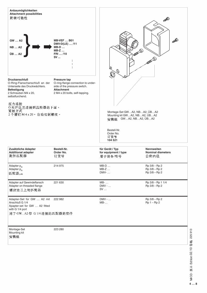
Zusätzliche AdapterAdditional adapter
Adapter pBrAdapter pBr
Adapter auf GewindeflanschAdapter on threaded flange
Adapter-Set für GW … A2 mit Anschluß G 1/4Apapter-set for GW … A2 fitted with G 1/4 port
Montage-SetMounting kit
Bestell-Nr.Order No.
214 975
221 630
222 982
223 280
für Gerät / Typfor equipment / type
MB-D …MB-Z …DMV- …
MB- …DMV - …SV …
DMV - …MB-…
AnbaumöglichkeitenAttachment possibilities
GW … A2
NB … A2
ÜB … A2}➡ ➡
MB-VEF … B01DMV-D(LE) … /11MB-D …MB-Z …FRI … /10SV ...
:::
DruckanschlußO-Ring-Flanschanschluß an der Unterseite des Druckwächters.Befestigung2 Schrauben M4 x 20,selbstfurchend.
Bestell-Nr.Order No.
104 521
NennweitenNominal diameters
Rp 3/8 – Rp 2Rp 3/8 – Rp 2Rp 3/8 – Rp 2
Rp 3/8 – Rp 1 1/4Rp 3/8 – Rp 2
Rp 3/8 – Rp 2Rp 1 – Rp 2
Pressure tapO-ring-flange connection to under-side of the pressure switch.Attachment2 M4 x 20 bolts, self-tapping.
Montage-Set GW…A2, NB…A2, ÜB…A2Mounting kit GW…A2, NB…A2, ÜB…A2 GW…A2, NB…A2, ÜB…A2
5 … 8
225
913
02.1
0
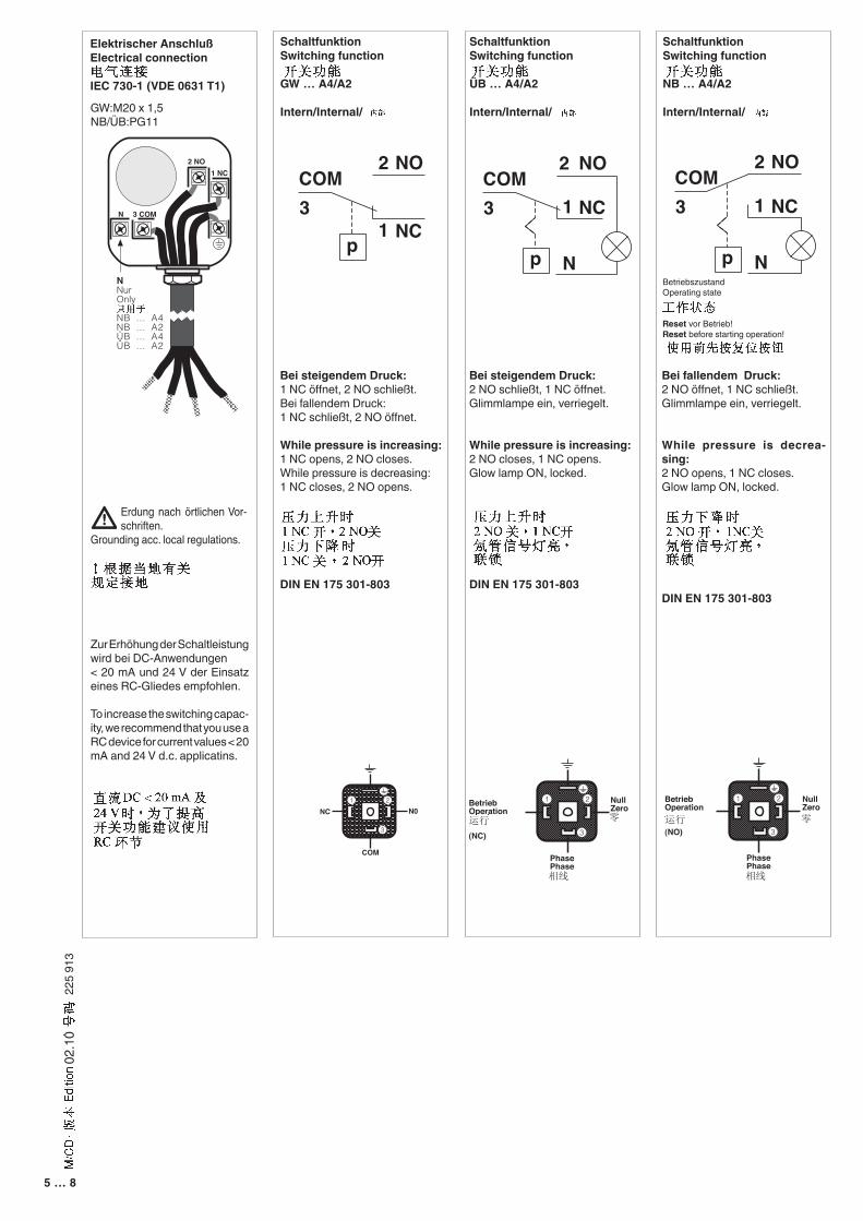
SchaltfunktionSwitching function
NB … A4/A2
Intern/Internal/
SchaltfunktionSwitching function
ÜB … A4/A2
Intern/Internal/
SchaltfunktionSwitching function
GW … A4/A2
Intern/Internal/
BetriebszustandOperating state
Reset vor Betrieb!Reset before starting operation!
Bei fallendem Druck:2 NO öffnet, 1 NC schließt.Glimmlampe ein, verriegelt.
While pressure is decrea-sing:2 NO opens, 1 NC closes.Glow lamp ON, locked.
DIN EN 175 301-803
Erdung nach örtlichen Vor-schriften.
Grounding acc. local regulations.
1 NC2 NO
3 COMN
NNurOnly
NB … A4NB … A2ÜB … A4ÜB … A2
Bei steigendem Druck:1 NC öffnet, 2 NO schließt.Bei fallendem Druck:1 NC schließt, 2 NO öffnet.
While pressure is increasing:1 NC opens, 2 NO closes.While pressure is decreasing:1 NC closes, 2 NO opens.
DIN EN 175 301-803
Bei steigendem Druck:2 NO schließt, 1 NC öffnet.Glimmlampe ein, verriegelt.
While pressure is increasing:2 NO closes, 1 NC opens.Glow lamp ON, locked.
DIN EN 175 301-803
p
COMNO
NC
2
13
COMNO
NC
2
1
p
3
N
COMNO
NC
2
1
p
3
N
p
COMNO
NC
2
13
COMNO
NC
2
1
p
3
N
COMNO
NC
2
1
p
3
N
p
COMNO
NC
2
13
COMNO
NC
2
1
p
3
N
COMNO
NC
2
1
p
3
N
Zur Erhöhung der Schaltleistung wird bei DC-Anwendungen < 20 mA und 24 V der Einsatz eines RC-Gliedes empfohlen.
To increase the switching capac-ity, we recommend that you use a RC device for current values < 20 mA and 24 V d.c. applicatins.
Elektrischer AnschlußElectrical connection
IEC 730-1 (VDE 0631 T1)
GW:M20 x 1,5NB/ÜB:PG11
NC N01 2
3
COM
1 2
3
1 2
3
BetriebOperation
(NC)
PhasePhase
NullZero
BetriebOperation
(NO)
PhasePhase
NullZero
NC N01 2
3
COM
1 2
3
1 2
3
BetriebOperation
(NC)
PhasePhase
NullZero
BetriebOperation
(NO)
PhasePhase
NullZero
运行 零
相线
NC N01 2
3
COM
1 2
3
1 2
3
BetriebOperation
(NC)
PhasePhase
NullZero
BetriebOperation
(NO)
PhasePhase
NullZero
运行 零
相线
6 … 8
225
913
02.1
0
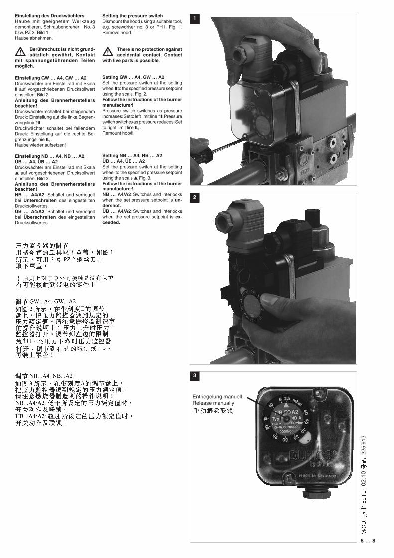
Setting the pressure switch Dismount the hood using a suitable tool, e.g. screwdriver no. 3 or PH1, Fig. 1. Remove hood.
There is no protection against accidental contact. Contact
with live parts is possible.
Setting GW … A4, GW … A2 Set the pressure switch at the setting wheel ❚ to the specified pressure setpoint using the scale, Fig. 2.Follow the instructions of the burner manufacturer!Pressure switch switches as pressure increases: Set to left limit line ↑❚. Pressure switch switches as pressure reduces: Set to right limit line ❚↓.Remount hood!
Setting NB … A4, NB … A2ÜB … A4, ÜB … A2Set the pressure switch at the setting wheel to the specified pressure setpoint using the scale ▲ Fig. 3.Follow the instructions of the burner manufacturer!NB … A4/A2: Switches and interlocks when the set pressure setpoint is un-dershot. ÜB … A4/A2: Switches and interlocks when the set pressure setpoint is ex-ceeded.
Einstellung des DruckwächtersHaube mit geeignetem Werkzeug demontieren, Schraubendreher No. 3 bzw. PZ 2, Bild 1.Haube abnehmen.
Berührschutz ist nicht grund-sätzlich gewährt, Kontakt
mit spannungsführenden Teilen möglich.
Einstellung GW … A4, GW … A2Druckwächter am Einstellrad mit Skala ❚ auf vorgeschriebenen Drucksollwert einstellen, Bild 2.Anleitung des Brennerherstellers beachten!Druckwächter schaltet bei steigendem Druck: Einstellung auf die linke Begren-zungslinie↑❚. Druckwächter schaltet bei fallendem Druck: Einstellung auf die rechte Be-grenzungslinie ❚↓.Haube wieder aufsetzen!
Einstellung NB … A4, NB … A2ÜB … A4, ÜB … A2Druckwächter am Einstellrad mit Skala ▲ auf vorgeschriebenen Drucksollwert einstellen, Bild 3.Anleitung des Brennerherstellers beachten!NB … A4/A2: Schaltet und verriegelt bei Unterschreiten des eingestellten Drucksollwertes.ÜB … A4/A2: Schaltet und verriegelt bei Überschreiten des eingestellten Drucksollwertes.
1
3
2
Entriegelung manuellRelease manually
7 … 8
225
913
02.1
0
Rohrleitungsdichtheits-prüfung: Kugelhahn vor dem Druckwächter schließen.
Nach Abschluß von Ar-beiten am Druckwäch-ter: Dichtheitskontrolle und Funktionskontrolle durchführen.
Niemals Arbeiten durch-führen, wenn Gasdruck oder Spannung anliegt. Offenes Feuer vermeiden. Örtliche Vorschriften be-achten.
Bei Nichtbeachtung der Hinweise sind Personen- oder Sachfolgeschäden denkbar.
Pipeline leakage test: clo-se ball valve upstream of the pressure switch.
On completion of work on the pressure switch, perform a leakage and function test.
Never perform work if gas pressure or power is applied. No naked flame. Observe local regulat-ions.
If these instructions are not heeded, the result may be personal injury or damage to property.
Kondensat darf nicht in das Gerät gelangen kann. Bei Minustemperaturen, durch Vereisung Fehl-funktion/Ausfall mög-lich.
Do not allow condensate to flow into the equipment. In case of sub-zero tem-peratures, malfunction or equipment failure may be possible due to icing.
Arbeiten am Druckwäch-ter dürfen nur von Fach-personal durchgeführt werden.
Work on the pressu-re switch may only be performed by specialist staff.
Safetyfirst
O.K.
避免周围环境中有硅油和挥发性硅酮成分(硅氧烷)的存在。否则有造成故障/失灵的可能。
Silikonöle und flüchtige Silikonbestandteile (Siloxane) in der Umgebung vermeiden. Fehlfunktion / Ausfall möglich.
Avoid silicone oils and volatile silicones (siloxanes) in the environment. Malfunction/failure possible.
Alle Einstellungen und Ein-stellwerte nur in Überein-stimmung mit der Betriebs-anleitung des Kessel-/Brennerherstellers ausfüh-ren.
Any adjustment and appli-cation-specific adjustment values must be made in accordance with the appli-ance-/boiler manufacturers instructions.
所有调节须按照锅炉/燃烧器制造商的使用手册进行。
8 … 8
225
913
02.1
0
Die Druckgeräterichtlinie (PED) und die Richtlinie über die Gesamtener-gieeffizienz von Gebäu-den (EPBD) fordern eine regelmässige Überprüfung von Heizungsanlagen zur langfristigen Sicherstel-lung von hohen Nutzungs-graden und somit gering-ster Umweltbelastung. Es besteht die Notwendig-keit sicherheitsrelevante Komponenten nach Er-reichen ihrer Nutzungs-dauer auszutauschen. Diese Empfehlung gilt nur für Heizungsanla-gen und nicht für Ther-mprozessanwendungen. DUNGS empfiehlt den Austausch gemäss fol-gender Tabelle:
按照压力器械指令(PED)和建筑物总能源效率指令(EPBD)的要求,要对采暖设备定期进行检查,以便长期确保高度的利用率和最低的环境负荷。对于和安全相关的组件,当达到其使用期限时,要予以更换。此建议仅适用于采暖设备,而不适用于工业加热过程应用场合。东斯公司建议根据以下表格实施更换工作:
Sicherheitsrelevante KomponenteSafety relevant component和安全相关的组件
NUTZUNGSDAUERDUNGS empfiehlt den Austausch nach:USEFUL LIFEDUNGS recommends replacement after:使用期限东斯公司建议更换按照:
SchaltspieleOperating cycles操作循环次数
Ventilprüfsysteme / Valve proving systems 阀门检漏系统
10 Jahre/years 10年 250.000
Druckwächter / Pressure switch / 调压阀 10 Jahre/years 10年 N/AFeuerungsmanager mit FlammenwächterAutomatic burner control with flame safe guard带火焰调节器的自动燃烧器
10 Jahre/years 10年 250.000
UV-FlammenfühlerFlame detector (UV probes)紫外线火焰传感器
10.000 h Betriebsstunden/Operating hours / 工作小时
Gasdruckregelgeräte / Gas pressure regulators燃气压力开关
15 Jahre/years 15年 N/A
Gasventil mit Ventilprüfsystem / Gas valve with valve testing system带阀门检漏系统的燃气阀
nach erkanntem Fehlerafter error detection按照发现的错误
Gasventil ohne Ventilprüfsystem* / Gas valve without valve testing system*无阀门检漏系统的燃气阀*
10 Jahre/years 10年 250.000
Min. Gasdruckwächter / Low gas pressure switch最小燃气调压阀
10 Jahre/years 10年 N/A
Sicherheitsabblaseventil / Pressure relief valve安全阀
10 Jahre/years 10年 N/A
Gas-Luft-Verbundsysteme / Gas-air-ratio control system燃气空气联合系统
10 Jahre/years 10年 N/A
* Gasfamilien I, II, III / Gas families I, II, III N/A kann nicht verwendet werden / not applicable / N/A - 不适用 *I, II, III类燃气
The Pressure Equipment Directive (PED) and the Energy Performance of Buildings Directive (EPBD) require a periodic inspec-tion of heating applianc-es in order to ensure a high degree of efficiency over a long term and, consequent-ly, the least environmental pollution. It is necessary to replace safety-rele-vant components after they have reached the end of their useful life. This recommendation applies only to heating appliances and not to industrial heating proc-esses. DUNGS recom-mends replacing such components according to the following table:
Karl Dungs GmbH & Co. KG Siemensstraße 6-10 D-73660 Urbach, GermanyTelefon +49 (0)7181-804-0Telefax +49 (0)7181-804-166
e-mail [email protected] www.dungs.com