Embed Size (px)
DESCRIPTION
http://www.dungs.com/fileadmin/media/Downloads/DBs_BMAs/229331.pdf?1290008160
Citation preview
1 … 16
229
331
02.1
0
� ��� �
��� ��� �
� ��� �
�� �� �����
�� ���� �
��� �� ���� �� ���� �� �� �� ��
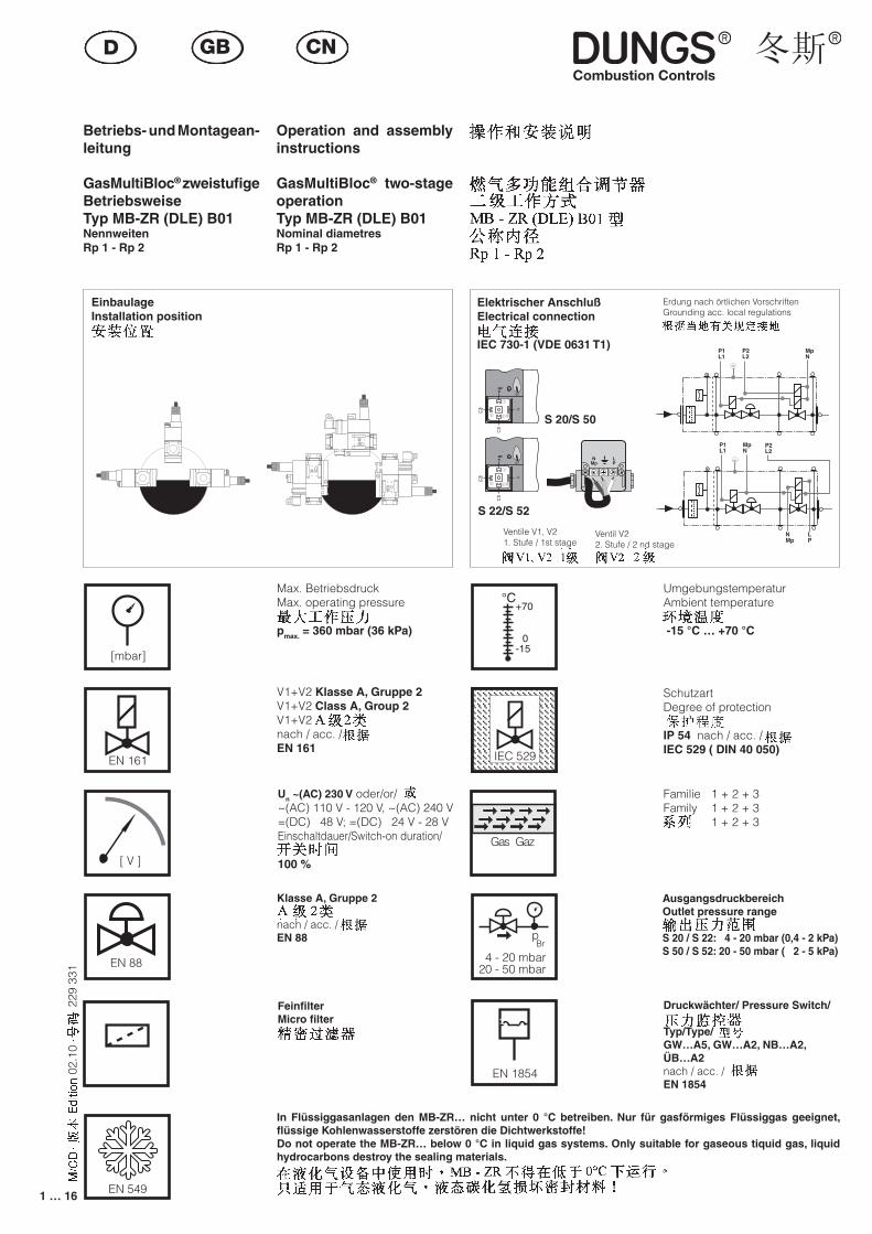
��� �� �� ���Betriebs- und Montagean-leitung
GasMultiBloc® zweistufige BetriebsweiseTyp MB-ZR (DLE) B01NennweitenRp 1 - Rp 2
Operation and assembly instructions
GasMultiBloc® two-stage operationTyp MB-ZR (DLE) B01Nominal diametresRp 1 - Rp 2
EinbaulageInstallation position
Elektrischer AnschlußElectrical connection
IEC 730-1 (VDE 0631 T1)
Max. Betriebsdruck Max. operating pressure
pmax. = 360 mbar (36 kPa)
V1+V2 Klasse A, Gruppe 2V1+V2 Class A, Group 2V1+V2nach / acc. / EN 161
UmgebungstemperaturAmbient temperature
-15 °C … +70 °C
Schutzart Degree of protection
IP 54 nach / acc. / IEC 529 ( DIN 40 050)
Erdung nach örtlichen VorschriftenGrounding acc. local regulations
Familie 1 + 2 + 3Family 1 + 2 + 3 1 + 2 + 3
AusgangsdruckbereichOutlet pressure range
S 20 / S 22: 4 - 20 mbar (0,4 - 2 kPa)S 50 / S 52: 20 - 50 mbar ( 2 - 5 kPa)
Druckwächter/ Pressure Switch/
Typ/Type/GW…A5, GW…A2, NB…A2, ÜB…A2nach / acc. / EN 1854
FeinfilterMicro filter
Klasse A, Gruppe 2
nach / acc. / EN 88
Un ~(AC) 230 V oder/or/ ~(AC) 110 V - 120 V, ~(AC) 240 V =(DC) 48 V; =(DC) 24 V - 28 VEinschaltdauer/Switch-on duration/
100 %
In Flüssiggasanlagen den MB-ZR… nicht unter 0 °C betreiben. Nur für gasförmiges Flüssiggas geeignet, flüssige Kohlenwasserstoffe zerstören die Dichtwerkstoffe!Do not operate the MB-ZR… below 0 °C in liquid gas systems. Only suitable for gaseous tiquid gas, liquid hydrocarbons destroy the sealing materials.
Ventile V1, V21. Stufe / 1st stage
Ventil V22. Stufe / 2 nd stage
[mbar]
EN 161
[ V ]
EN 88
EN 549
��
�
���
���
IEC 529IEC 529
Gas Gaz
EN 1854
4 - 20 mbar20 - 50 mbar
pBr
P2L2
P1L1
MPN
1
23
P2L2
P1L1
MPN
1
23
P1L1
P2L2
MpN
2 1
3
NMp
LP
S 20/S 50
S 22/S 52
PL
PL
MpN
P1L1
MpN
P2L2
NMp
LP
P1L1
MpN
P2L2
PL
PL
MpN
P1L1
MpN
P2L2
NMp
LP
P1L1
MpN
P2L2
2 … 16
229
331
02.1
0
Rp
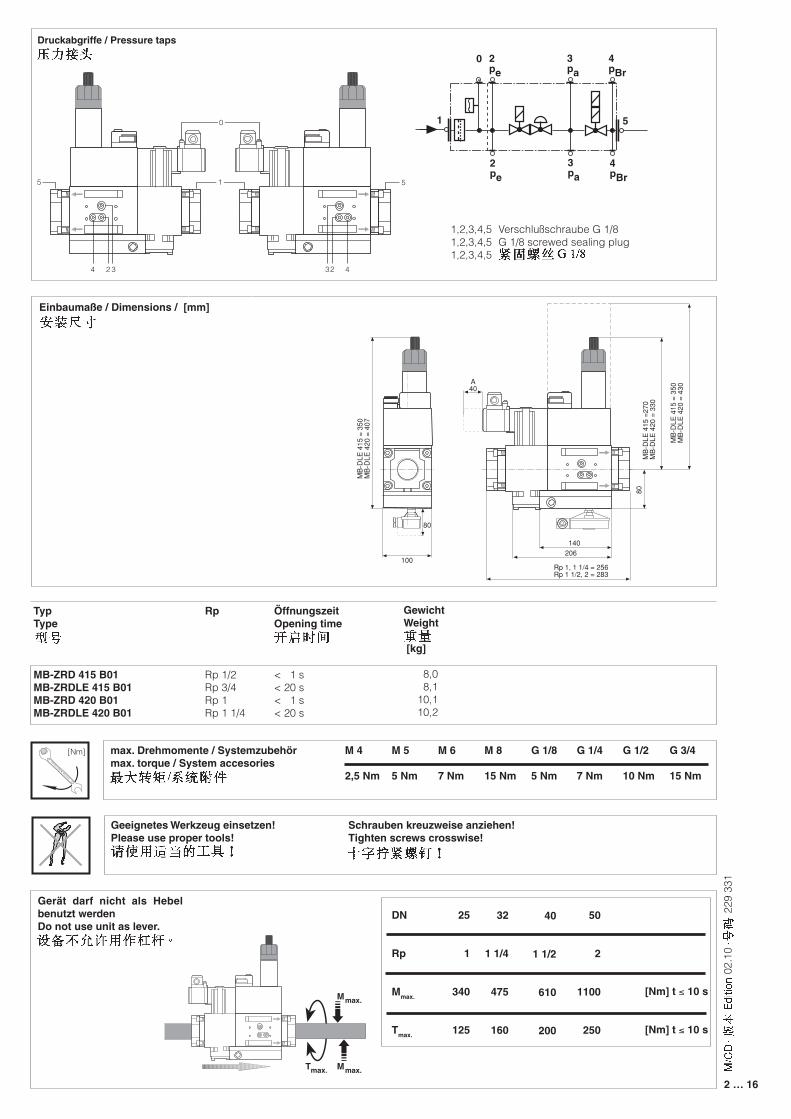
Rp 1/2Rp 3/4Rp 1Rp 1 1/4
GewichtWeight
[kg]
8,0 8,110,110,2
TypType
MB-ZRD 415 B01MB-ZRDLE 415 B01MB-ZRD 420 B01MB-ZRDLE 420 B01
ÖffnungszeitOpening time
< 1 s< 20 s< 1 s< 20 s
Druckabgriffe / Pressure taps
Einbaumaße / Dimensions / [mm]
1,2,3,4,5 Verschlußschraube G 1/81,2,3,4,5 G 1/8 screwed sealing plug1,2,3,4,5
max. Drehmomente / Systemzubehörmax. torque / System accesories
M 5
5 Nm
M 6
7 Nm
G 1/8
5 Nm
G 1/4
7 Nm
G 1/2
10 Nm
G 3/4
15 Nm
M 8
15 Nm
M 4
2,5 Nm
Geeignetes Werkzeug einsetzen! Schrauben kreuzweise anziehen!Please use proper tools! Tighten screws crosswise!
Gerät darf nicht als Hebel benutzt werdenDo not use unit as lever.
DN
Rp
Mmax.
Tmax.
[Nm] t ≤ 10 s
[Nm] t ≤ 10 s
50
2
1100
250
40
1 1/2
610
200
32
1 1/4
475
160
25
1
340
125
A40
100
MB
-DLE
415
= 3
50M
B-D
LE 4
20 =
407
80
Rp 1, 1 1/4 = 256Rp 1 1/2, 2 = 283
140
MB
-DLE
415
=27
0M
B-D
LE 4
20 =
330
80
MB
-DLE
415
= 3
50M
B-D
LE 4
20 =
430
206
[Nm]
18
19
15
4 32 432
5
0 1 5
2pe
3pa
4pBr
2pe
3pa
4pBr
0
3 … 16
229
331
02.1
0
Druckwächter
Pressure switch
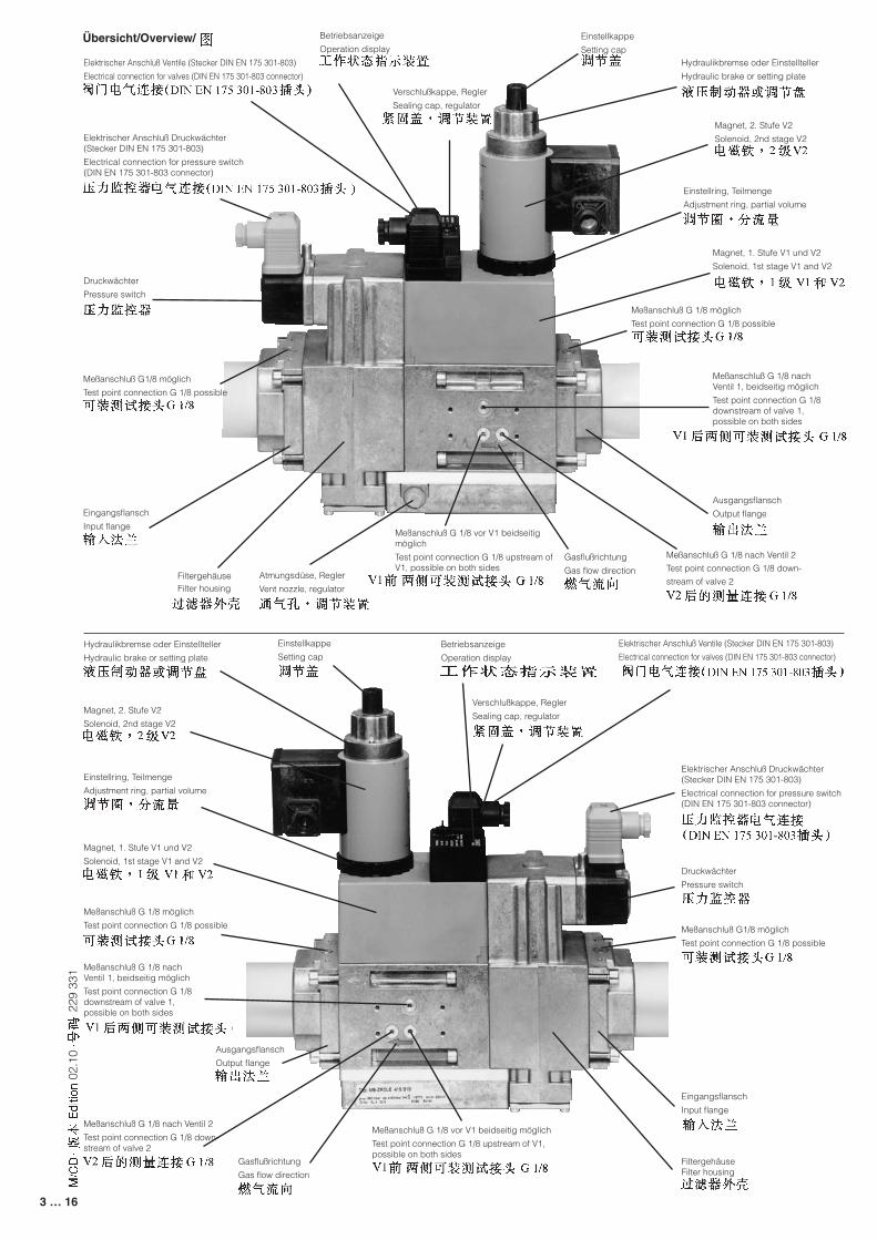
Übersicht/Overview/
Elektrischer Anschluß Druckwächter (Stecker DIN EN 175 301-803)
Electrical connection for pressure switch (DIN EN 175 301-803 connector)
Meßanschluß G1/8 möglich
Test point connection G 1/8 possible
Atmungsdüse, Regler
Vent nozzle, regulator
Meßanschluß G 1/8 vor V1 beidseitig möglich
Test point connection G 1/8 upstream of V1, possible on both sides
Gasflußrichtung
Gas flow direction
Meßanschluß G 1/8 nach Ventil 2
Test point connection G 1/8 down-
stream of valve 2
Ausgangsflansch
Output flangeEingangsflansch
Input flange
FiltergehäuseFilter housing
Elektrischer Anschluß Ventile (Stecker DIN EN 175 301-803)
Electrical connection for valves (DIN EN 175 301-803 connector)
Betriebsanzeige
Operation display Einstellkappe
Setting cap
Verschlußkappe, Regler
Sealing cap, regulator
Meßanschluß G 1/8 nach Ventil 1, beidseitig möglich
Test point connection G 1/8 downstream of valve 1, possible on both sides
Meßanschluß G 1/8 möglich
Test point connection G 1/8 possible
Magnet, 1. Stufe V1 und V2
Solenoid, 1st stage V1 and V2
Hydraulikbremse oder Einstellteller
Hydraulic brake or setting plate
Einstellring, Teilmenge
Adjustment ring, partial volume
Magnet, 2. Stufe V2
Solenoid, 2nd stage V2
Elektrischer Anschluß Druckwächter (Stecker DIN EN 175 301-803)
Electrical connection for pressure switch (DIN EN 175 301-803 connector)
Druckwächter
Pressure switch
Meßanschluß G1/8 möglich
Test point connection G 1/8 possible
Eingangsflansch
Input flange
Einstellring, Teilmenge
Adjustment ring, partial volume
Meßanschluß G 1/8 möglich
Test point connection G 1/8 possible
Meßanschluß G 1/8 nach Ventil 2
Test point connection G 1/8 down-stream of valve 2
Meßanschluß G 1/8 nach Ventil 1, beidseitig möglich
Test point connection G 1/8 downstream of valve 1, possible on both sides
Magnet, 1. Stufe V1 und V2
Solenoid, 1st stage V1 and V2
Magnet, 2. Stufe V2
Solenoid, 2nd stage V2
Hydraulikbremse oder Einstellteller
Hydraulic brake or setting plate
Einstellkappe
Setting cap
Verschlußkappe, Regler
Sealing cap, regulator
Betriebsanzeige
Operation display
Elektrischer Anschluß Ventile (Stecker DIN EN 175 301-803)
Electrical connection for valves (DIN EN 175 301-803 connector)
Meßanschluß G 1/8 vor V1 beidseitig möglich
Test point connection G 1/8 upstream of V1, possible on both sides
Ausgangsflansch
Output flange
Gasflußrichtung
Gas flow direction
FiltergehäuseFilter housing
4 … 16
229
331
02.1
0
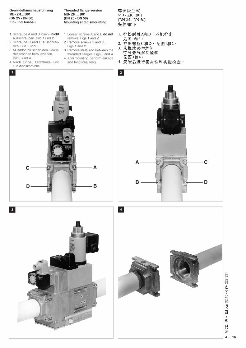
GewindeflanschausführungMB- ZR... B01(DN 25 - DN 50)Ein- und Ausbau
1. Schraube A und B lösen - nicht ausschrauben. Bild 1 und 2
2. Schraube C und D ausschrau-ben. Bild 1 und 2
3. MultiBloc zwischen den Gewin-deflanschen herausziehen.
Bild 3 und 44. Nach Einbau Dichtheits- und
Funktionskontrolle.
Threaded flange versionMB- ZR… B01(DN 25 - DN 50)Mounting and dismounting
1. Loosen screws A and B do not remove. Figs 1 and 2
2. Remove screws C and D. Figs 1 and 23. Remove MultiBloc between the
threaded flanges. Figs 3 and 44. After mounting, perform leakage
and functional tests.
21
43
A
B
C
D
C
D
A
B
5 … 16
229
331
02.1
0
1
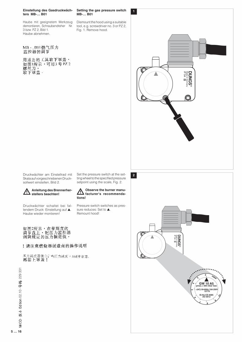
2Druckwächter am Einstellrad mit Skala auf vorgeschriebenen Druck-sollwert einstellen, Bild 2.
Anleitung des Brennerher-stellers beachten!
Druckwächter schaltet bei fal-lendem Druck: Einstellung auf ▲.Haube wieder montieren!
Set the pressure switch at the set-ting wheel to the specified pressure setpoint using the scale, Fig. 2.
Observe the burner manu-facturer's recommenda-
tions!
Pressure switch switches as pres-sure reduces: Set to ▲. Remount hood!
Einstellung des Gasdruckwäch-ters MB-… B01
Haube mit geeignetem Werkzeug demontieren, Schraubendreher Nr. 3 bzw. PZ 2, Bild 1.Haube abnehmen.
Setting the gas pressure switch MB-… B01
Dismount the hood using a suitable tool, e.g. screwdriver no. 3 or PZ 2, Fig. 1. Remove hood.
Made in G
ermany
IP 54
NO NC
2 1
2
8
3
45
6
79
10
mbar
GW 10 A5pmax.= 500 mbar Gas
~(AC) 50-60Hz 10A 250V 15T70
ID.No:CE-0085AO 0012
Made in G
ermany
IP 54
6 … 16
229
331
02.1
0
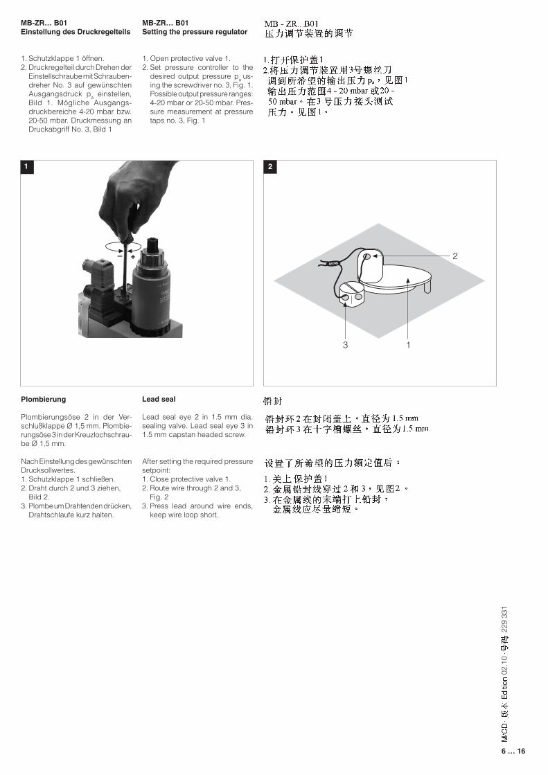
MB-ZR… B01Einstellung des Druckregelteils
1. Schutzklappe 1 öffnen.2. Druckregelteil durch Drehen der
Einstellschraube mit Schrauben-dreher No. 3 auf gewünschten Ausgangsdruck pa einstellen, Bild 1. Mögliche Ausgangs-druckbereiche 4-20 mbar bzw. 20-50 mbar. Druckmessung an Druckabgriff No. 3, Bild 1
MB-ZR… B01Setting the pressure regulator
1. Open protective valve 1.2. Set pressure controller to the
desired output pressure pa us-ing the screwdriver no. 3, Fig. 1. Possible output pressure ranges: 4-20 mbar or 20-50 mbar. Pres-sure measurement at pressure taps no. 3, Fig. 1
1 2
Plombierung
Plombierungsöse 2 in der Ver-schlußklappe Ø 1,5 mm. Plombie-rungsöse 3 in der Kreuzlochschrau-be Ø 1,5 mm.
Nach Einstellung des gewünschten Drucksollwertes.1. Schutzklappe 1 schließen.2. Draht durch 2 und 3 ziehen, Bild 2.3. Plombe um Drahtenden drücken,
Drahtschlaufe kurz halten.
Lead seal
Lead seal eye 2 in 1.5 mm dia. sealing valve. Lead seal eye 3 in 1.5 mm capstan headed screw.
After setting the required pressure setpoint:1. Close protective valve 1.2. Route wire through 2 and 3, Fig. 23. Press lead around wire ends,
keep wire loop short.
2
3
05/98
1
+–
+ –
+ –
+ –
+ –
+ –
7 … 16
229
331
02.1
0
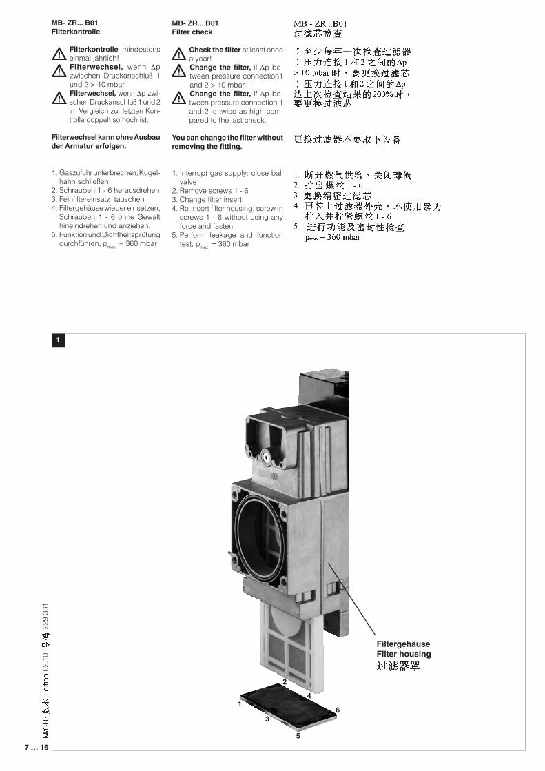
MB- ZR... B01Filterkontrolle
Filterkontrolle mindestens einmal jährlich!Filterwechsel, wenn ∆p zwischen Druckanschluß 1 und 2 > 10 mbar.Filterwechsel, wenn ∆p zwi-schen Druckanschluß 1 und 2 im Vergleich zur letzten Kon-trolle doppelt so hoch ist.
Filterwechsel kann ohne Ausbau der Armatur erfolgen.
1. Gaszufuhr unterbrechen, Kugel-hahn schließen
2. Schrauben 1 - 6 herausdrehen3. Feinfiltereinsatz tauschen4. Filtergehäuse wieder einsetzen,
Schrauben 1 - 6 ohne Gewalt hineindrehen und anziehen.
5. Funktion und Dichtheitsprüfung durchführen, pmax. = 360 mbar
MB- ZR... B01Filter check
Check the filter at least once a year!Change the filter, il ∆p be-tween pressure connection1 and 2 > 10 mbar.Change the filter, if ∆p be-tween pressure connection 1 and 2 is twice as high com-pared to the last check.
You can change the filter without removing the fitting.
1. Interrupt gas supply: close ball valve
2. Remove screws 1 - 63. Change filter insert 4. Re-insert filter housing, screw in
screws 1 - 6 without using any force and fasten.
5. Perform leakage and function test, pmax. = 360 mbar
1
FiltergehäuseFilter housing
3
14
2
5
6
8 … 16
229
331
02.1
0
+–
+–
+–
+–
+–
+–
��������
���
���
�������������������
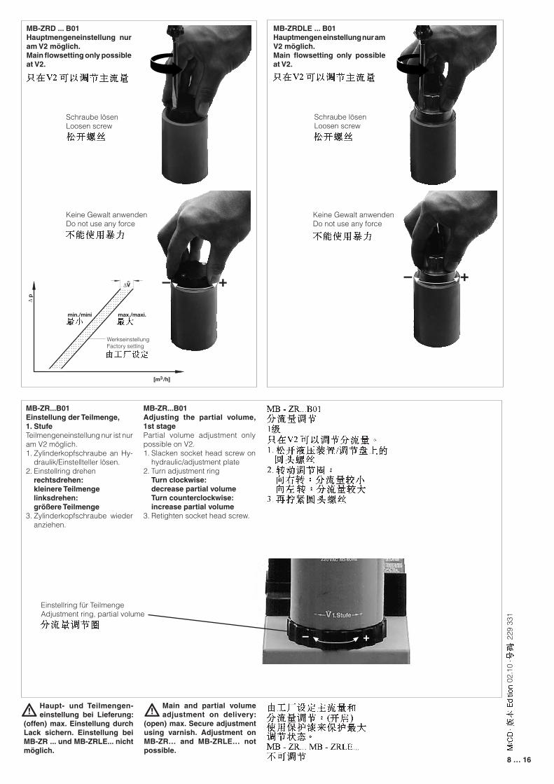
Main and partial volume adjustment on delivery:
(open) max. Secure adjustment using varnish. Adjustment on MB-ZR… and MB-ZRLE… not possible.
Haupt- und Teilmengen-einstellung bei Lieferung:
(offen) max. Einstellung durch Lack sichern. Einstellung bei MB-ZR ... und MB-ZRLE... nicht möglich.
MB-ZR...B01Einstellung der Teilmenge, 1. StufeTeilmengeneinstellung nur ist nur am V2 möglich.1. Zylinderkopfschraube an Hy-
draulik/Einstellteller lösen.2. Einstellring drehen rechtsdrehen: kleinere Teilmenge linksdrehen: größere Teilmenge3. Zylinderkopfschraube wieder
anziehen.
MB-ZR...B01Adjusting the partial volume, 1st stagePartial volume adjustment only possible on V2.1. Slacken socket head screw on
hydraulic/adjustment plate2. Turn adjustment ring Turn clockwise: decrease partial volume Turn counterclockwise: increase partial volume3. Retighten socket head screw.
Einstellring für TeilmengeAdjustment ring, partial volume
MB-ZRD ... B01 Hauptmengeneinstellung nur am V2 möglich.Main flowsetting only possible at V2.
MB-ZRDLE ... B01Hauptmengen einstellung nur am V2 möglich.Main flowsetting only possible at V2.
Keine Gewalt anwendenDo not use any force
Schraube lösenLoosen screw
Keine Gewalt anwendenDo not use any force
Schraube lösenLoosen screw
WerkseinstellungFactory setting
+–
+–
+–
+–
+–
+–
+–
+–
+–
+–
9 … 16
229
331
02.1
0
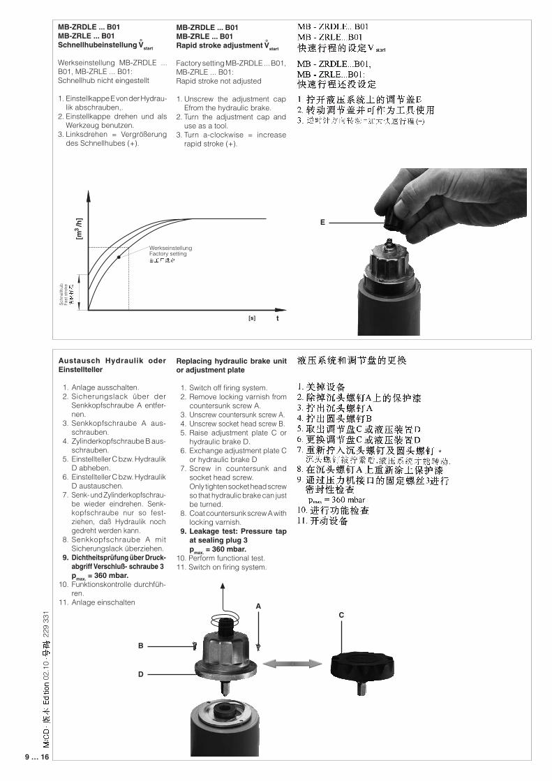
Replacing hydraulic brake unit or adjustment plate
1. Switch off firing system. 2. Remove locking varnish from
countersunk screw A. 3. Unscrew countersunk screw A. 4. Unscrew socket head screw B. 5. Raise adjustment plate C or
hydraulic brake D. 6. Exchange adjustment plate C
or hydraulic brake D 7. Screw in countersunk and
socket head screw. Only tighten socket head screw
so that hydraulic brake can just be turned.
8. Coat countersunk screw A with locking varnish.
9. Leakage test: Pressure tap at sealing plug 3
pmax. = 360 mbar.10. Perform functional test.11. Switch on firing system.
Austausch Hydraulik oder Einstellteller
1. Anlage ausschalten. 2. Sicherungslack über der
Senkkopfschraube A entfer-nen.
3. Senkkopfschraube A aus-schrauben.
4. Zylinderkopfschraube B aus-schrauben.
5. Einstellteller C bzw. Hydraulik D abheben.
6. Einstellteller C bzw. Hydraulik D austauschen.
7. Senk- und Zylinderkopfschrau-be wieder eindrehen. Senk-kopfschraube nur so fest-ziehen, daß Hydraulik noch gedreht werden kann.
8. Senkkopfschraube A mit Sicherungslack überziehen.
9. Dichtheitsprüfung über Druck-abgriff Verschluß- schraube 3
pmax. = 360 mbar.10. Funktionskontrolle durchfüh-
ren.11. Anlage einschalten
MB-ZRDLE ... B01MB-ZRLE ... B01Schnellhubeinstellung Vstart
Werkseinstellung MB-ZRDLE ... B01, MB-ZRLE ... B01:Schnellhub nicht eingestellt
1. Einstellkappe E von der Hydrau-lik abschrauben,.
2. Einstellkappe drehen und als Werkzeug benutzen.
3. Linksdrehen = Vergrößerung des Schnellhubes (+).
°
MB-ZRDLE ... B01MB-ZRLE ... B01Rapid stroke adjustment Vstart
Factory setting MB-ZRDLE ... B01, MB-ZRLE ... B01:Rapid stroke not adjusted
1. Unscrew the adjustment cap Efrom the hydraulic brake.
2. Turn the adjustment cap and use as a tool.
3. Turn a-clockwise = increase rapid stroke (+).
°
[m /
h]
3
[s] t
WerkseinstellungFactory setting
Sch
nellh
ubFa
st s
troke
E
D
B
AC
10 … 16
229
331
02.1
0
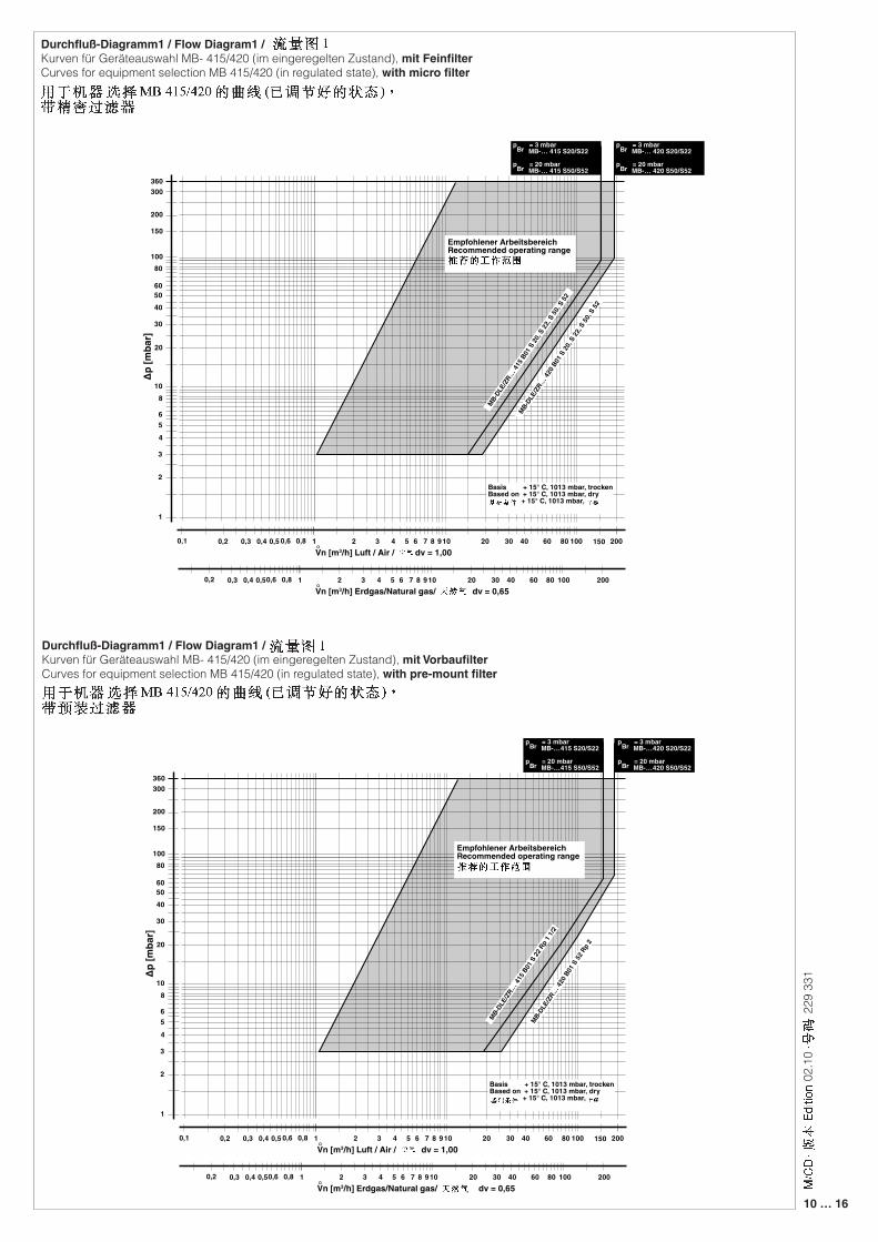
Durchfluß-Diagramm1 / Flow Diagram1 /Kurven für Geräteauswahl MB- 415/420 (im eingeregelten Zustand), mit FeinfilterCurves for equipment selection MB 415/420 (in regulated state), with micro filter
Durchfluß-Diagramm1 / Flow Diagram1 / Kurven für Geräteauswahl MB- 415/420 (im eingeregelten Zustand), mit VorbaufilterCurves for equipment selection MB 415/420 (in regulated state), with pre-mount filter
∆p [m
bar]
Vn [m3/h] Luft / Air / dv = 1,00°
2
3
456
1
810
20
30
40
60
80100
50
2 3 4 5 61 7 8 910 20 30 40 60 80 100 200
Basis + 15° C, 1013 mbar, trockenBased on + 15° C, 1013 mbar, dry + 15° C, 1013 mbar,
0,1 0,2 0,3 0,4 0,5 0,6 0,8
200
300360
150
MB-DLE
/ZR…
415 B
01 S
20, S
22, S
50, S
52
pBr = 3 mbar MB-… 415 S20/S22
pBr = 20 mbar MB-… 415 S50/S52
Vn [m3/h] Erdgas/Natural gas/ dv = 0,65°2 3 4 5 61 7 8 910 20 30 40 60 80 100 2000,2 0,3 0,4 0,50,6 0,8
MB-DLE
/ZR…
420 B
01 S
20, S
22, S
50, S
52
150
pBr = 3 mbar MB-… 420 S20/S22
pBr = 20 mbar MB-… 420 S50/S52
Empfohlener ArbeitsbereichRecommended operating range
∆p [m
bar]
Vn [m3/h] Luft / Air / dv = 1,00°
2
3
456
1
810
20
30
40
60
80100
50
2 3 4 5 61 7 8 910 20 30 40 60 80 100 200
Basis + 15° C, 1013 mbar, trockenBased on + 15° C, 1013 mbar, dry + 15° C, 1013 mbar,
0,1 0,2 0,3 0,4 0,5 0,6 0,8
200
300360
150
MB-DLE
/ZR…
415 B
01 S
22 R
p 1 1
/2
pBr = 3 mbar MB-…415 S20/S22
pBr = 20 mbar MB-…415 S50/S52
Vn [m3/h] Erdgas/Natural gas/ dv = 0,65°2 3 4 5 61 7 8 910 20 30 40 60 80 100 2000,2 0,3 0,4 0,50,6 0,8
150
pBr = 3 mbar MB-…420 S20/S22
pBr = 20 mbar MB-…420 S50/S52
MB-DLE
/ZR…
420 B
01 S
52 R
p 2
Empfohlener ArbeitsbereichRecommended operating range
11 … 16
229
331
02.1
0
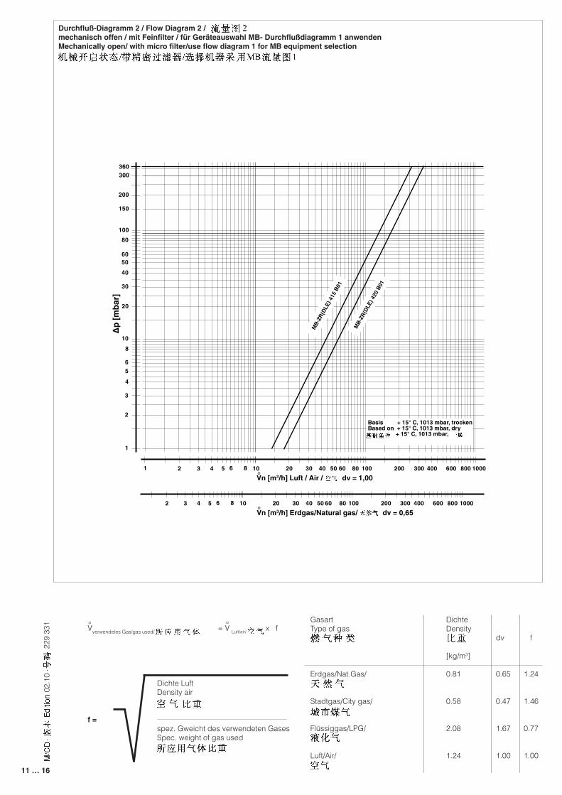
GasartType of gas
Erdgas/Nat.Gas/
Stadtgas/City gas/
Flüssiggas/LPG/
Luft/Air/
dv
0.65
0.47
1.67
1.00
f
1.24
1.46
0.77
1.00
Dichte LuftDensity air
spez. Gweicht des verwendeten GasesSpec. weight of gas used
f =
Vverwendetes Gas/gas used/ = ° V Luft/air/ x f °
Durchfluß-Diagramm 2 / Flow Diagram 2 /mechanisch offen / mit Feinfilter / für Geräteauswahl MB- Durchflußdiagramm 1 anwendenMechanically open/ with micro filter/use flow diagram 1 for MB equipment selection
DichteDensity
[kg/m3]
0.81
0.58
2.08
1.24
∆p [m
bar]
Vn [m3/h] Luft / Air / dv = 1,00°
2
3
456
1
810
20
30
40
60
80100
50
20 30 40 50 6010 80 100 200 300 400 600 800 10001 2 3 4 5 6 8
200
150
Vn [m3/h] Erdgas/Natural gas/ dv = 0,65°20 30 40 50 6010 80 100 200 300 400 600 800 10002 3 4 5 6 8
360300
MB-
ZR(D
LE) 4
15 B
01
MB-
ZR(D
LE) 4
20 B
01
Basis + 15° C, 1013 mbar, trockenBased on + 15° C, 1013 mbar, dry + 15° C, 1013 mbar,
12 … 16
229
331
02.1
0
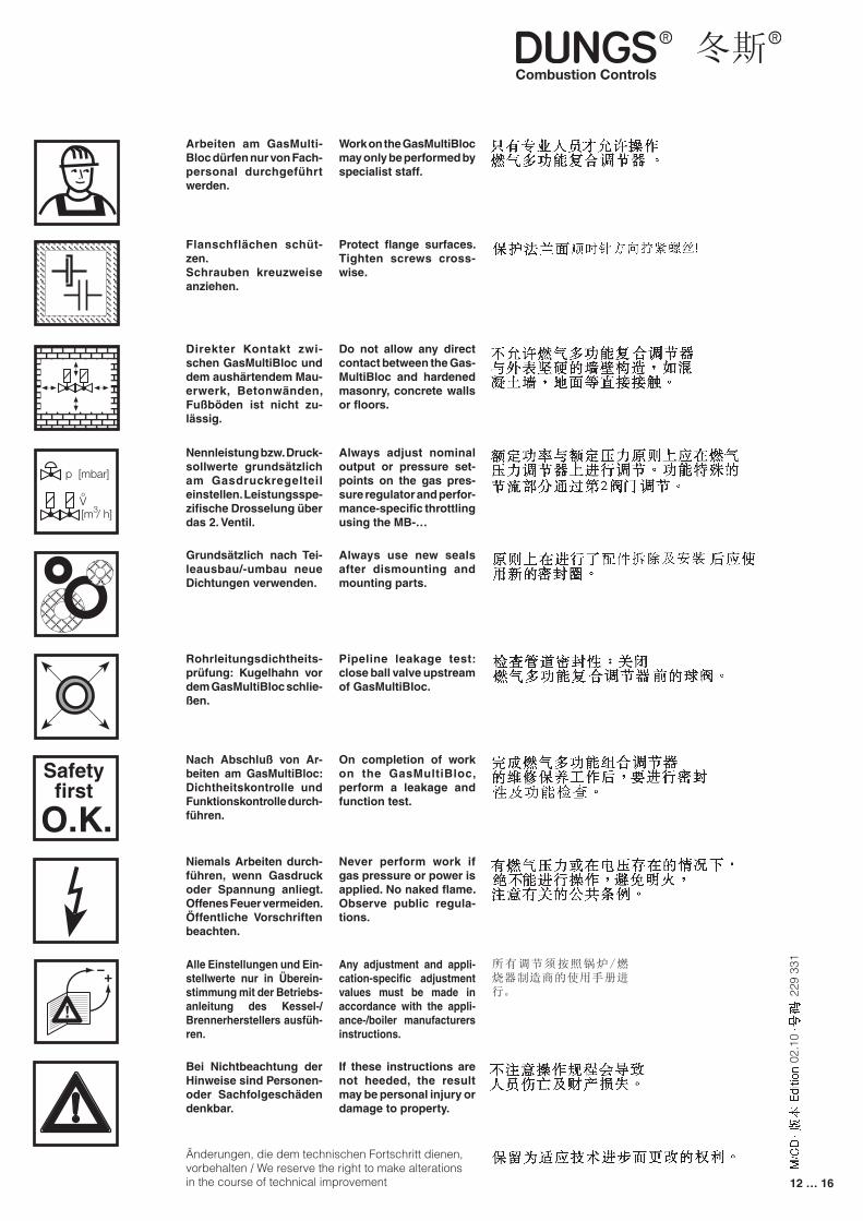
Arbeiten am GasMulti-Bloc dürfen nur von Fach-personal durchgeführt werden.
Flanschflächen schüt-zen.Schrauben kreuzweise anziehen.
Direkter Kontakt zwi-schen GasMultiBloc und dem aushärtendem Mau-erwerk, Betonwänden, Fußböden ist nicht zu-lässig.
Nennleistung bzw. Druck-sollwerte grundsätzlich am Gasdruckregelteil einstellen. Leistungsspe-zifische Drosselung über das 2. Ventil.
Grundsätzlich nach Tei-leausbau/-umbau neue Dichtungen verwenden.
Rohrleitungsdichtheits-prüfung: Kugelhahn vor dem GasMultiBloc schlie-ßen.
Nach Abschluß von Ar-beiten am GasMultiBloc: Dichtheitskontrolle und Funktionskontrolle durch-führen.
Niemals Arbeiten durch-führen, wenn Gasdruck oder Spannung anliegt. Offenes Feuer vermeiden. Öffentliche Vorschriften beachten.
Bei Nichtbeachtung der Hinweise sind Personen- oder Sachfolgeschäden denkbar.
Always use new seals after dismounting and mounting parts.
Pipeline leakage test: close ball valve upstream of GasMultiBloc.
On completion of work on the GasMultiBloc, perform a leakage and function test.
Never perform work if gas pressure or power is applied. No naked flame. Observe public regula-tions.
If these instructions are not heeded, the result may be personal injury or damage to property.
Work on the GasMultiBloc may only be performed by specialist staff.
Protect flange surfaces. Tighten screws cross-wise.
Do not allow any direct contact between the Gas-MultiBloc and hardened masonry, concrete walls or floors.
Always adjust nominal output or pressure set-points on the gas pres-sure regulator and perfor-mance-specific throttling using the MB-…
p [mbar]
[m / h]3V°
Safetyfirst
O.K.
Änderungen, die dem technischen Fortschritt dienen, vorbehalten / We reserve the right to make alterations in the course of technical improvement
Alle Einstellungen und Ein-stellwerte nur in Überein-stimmung mit der Betriebs-anleitung des Kessel-/Brennerherstellers ausfüh-ren.
Any adjustment and appli-cation-specific adjustment values must be made in accordance with the appli-ance-/boiler manufacturers instructions.
所有调节须按照锅炉/燃烧器制造商的使用手册进行。
13 … 16
229
331
02.1
0
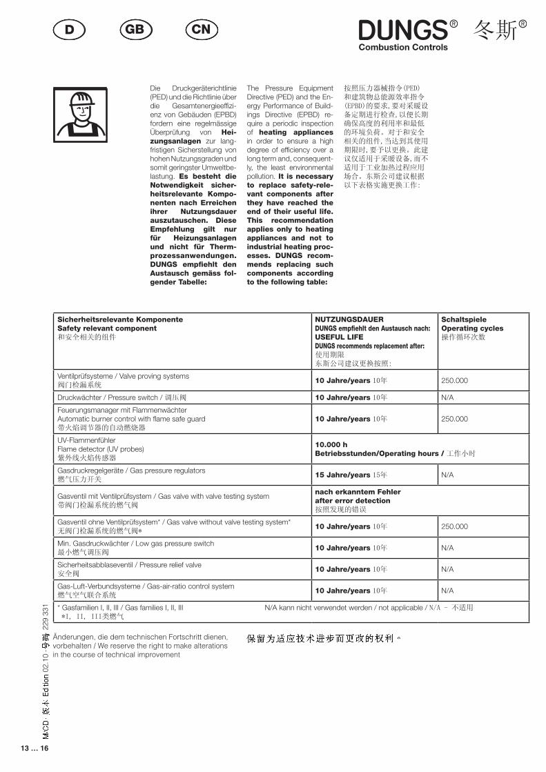
Die Druckgeräterichtlinie (PED) und die Richtlinie über die Gesamtenergieeffizi-enz von Gebäuden (EPBD) fordern eine regelmässige Überprüfung von Hei-zungsanlagen zur lang-fristigen Sicherstellung von hohen Nutzungsgraden und somit geringster Umweltbe-lastung. Es besteht die Notwendigkeit sicher-heitsrelevante Kompo-nenten nach Erreichen ihrer Nutzungsdauer auszutauschen. Diese Empfehlung gilt nur für Heizungsanlagen und nicht für Therm-prozessanwendungen. DUNGS empfiehlt den Austausch gemäss fol-gender Tabelle:
按照压力器械指令(PED)和建筑物总能源效率指令(EPBD)的要求,要对采暖设备定期进行检查,以便长期确保高度的利用率和最低的环境负荷。对于和安全相关的组件,当达到其使用期限时,要予以更换。此建议仅适用于采暖设备,而不适用于工业加热过程应用场合。东斯公司建议根据以下表格实施更换工作:
Sicherheitsrelevante KomponenteSafety relevant component和安全相关的组件
NUTZUNGSDAUERDUNGS empfiehlt den Austausch nach:USEFUL LIFEDUNGS recommends replacement after:使用期限东斯公司建议更换按照:
SchaltspieleOperating cycles操作循环次数
Ventilprüfsysteme / Valve proving systems 阀门检漏系统
10 Jahre/years 10年 250.000
Druckwächter / Pressure switch / 调压阀 10 Jahre/years 10年 N/A
Feuerungsmanager mit FlammenwächterAutomatic burner control with flame safe guard带火焰调节器的自动燃烧器
10 Jahre/years 10年 250.000
UV-FlammenfühlerFlame detector (UV probes)紫外线火焰传感器
10.000 h Betriebsstunden/Operating hours / 工作小时
Gasdruckregelgeräte / Gas pressure regulators燃气压力开关
15 Jahre/years 15年 N/A
Gasventil mit Ventilprüfsystem / Gas valve with valve testing system带阀门检漏系统的燃气阀
nach erkanntem Fehlerafter error detection按照发现的错误
Gasventil ohne Ventilprüfsystem* / Gas valve without valve testing system*无阀门检漏系统的燃气阀*
10 Jahre/years 10年 250.000
Min. Gasdruckwächter / Low gas pressure switch最小燃气调压阀
10 Jahre/years 10年 N/A
Sicherheitsabblaseventil / Pressure relief valve安全阀
10 Jahre/years 10年 N/A
Gas-Luft-Verbundsysteme / Gas-air-ratio control system燃气空气联合系统
10 Jahre/years 10年 N/A
* Gasfamilien I, II, III / Gas families I, II, III N/A kann nicht verwendet werden / not applicable / N/A - 不适用 *I, II, III类燃气
The Pressure Equipment Directive (PED) and the En-ergy Performance of Build-ings Directive (EPBD) re-quire a periodic inspection of heating appliances in order to ensure a high degree of efficiency over a long term and, consequent-ly, the least environmental pollution. It is necessary to replace safety-rele-vant components after they have reached the end of their useful life. This recommendation applies only to heating appliances and not to industrial heating proc-esses. DUNGS recom-mends replacing such components according to the following table:
� ��� �
��� ��� �
� ��� �
�� �� �����
�� ���� �
��� �� ���� �� ���� �� �� �� ��
��� �� �� ���
Änderungen, die dem technischen Fortschritt dienen, vorbehalten / We reserve the right to make alterations in the course of technical improvement

14 … 16
229
331
02.1
0

15 … 16
229
331
02.1
0
16 … 16
229
331
02.1
0
Karl Dungs GmbH & Co. KGSiemensstraße 6-10D-73660 Urbach, GermanyTelefon +49 (0)7181-804-0Telefax +49 (0)7181-804-166
e-mail [email protected] www.dungs.com