Embed Size (px)
Citation preview
544305 DE/EN
Robotino® Handbuch Robotino®
Manual
mit CD ROM CD-ROM included
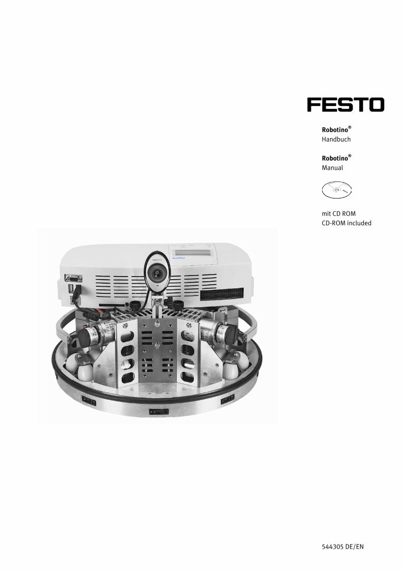
Das mobile Robotersystem Robotino®
ist ausschließlich für die Aus- und Weiterbildung im Bereich Automatisierung und Technik entwickelt und hergestellt. Das Ausbildungsunternehmen und/oder die Ausbildenden hat/haben dafür Sorge zu tragen, dass die Auszubildenden die Sicherheitsvorkehrungen, die in den begleitenden Handbüchern beschrieben sind, beachten. Festo Didactic schließt hiermit jegliche Haftung für Schäden des Auszubildenden, des Ausbildungsunternehmens und/oder sonstiger Dritter aus, die bei Gebrauch/Einsatz der Anlage außerhalb einer reinen Ausbildungssituation auftreten; es sei denn Festo Didactic hat solche Schäden vorsätzlich oder grob fahrlässig verursacht.
This mobile robot system Robotino®
Bestell-Nr./Order No.: 544305 Stand/Status: 11/2009 Autor/Author: Ralph-Christoph Weber, Markus Bellenberg Grafik/Graphics: Doris Schwarzenberger © Festo Didactic GmbH & Co. KG, 73770 Denkendorf, Germany, 2009 Internet: www.festo-didactic.com e-mail: [email protected] Weitergabe sowie Vervielfältigung dieses Dokuments, Verwertung und Mitteilung seines Inhalts verboten, soweit nicht ausdrücklich gestattet. Zuwiderhandlungen verpflichten zu Schadenersatz. Alle Rechte vorbehalten, insbesondere das Recht, Patent-, Gebrauchsmuster- oder Geschmacksmusteranmeldungen durchzuführen. The copying, distribution and utilisation of this document as well as the communication of its contents to others without express authorisation is prohibited. Offenders will be held liable for the payment of damages. All rights reserved, in particular the right to carry out patent, utility model or ornamental design registration.
has been developed and produced solely for vocational and further training purposes in the field of automation and technology. The company undertaking the training and/or the instructors is/are to ensure that trainees observe the safety precautions described in the manuals provided. Festo Didactic herewith excludes any liability for damage or injury caused to trainees, the training company and/or any third party, which may occur if the system is in use for purposes other than purely for training, unless the said damage/injury has been caused by Festo Didactic deliberately or through gross negligence.
Bestimmungsgemäße Verwendung/Intended use
© Festo Didactic GmbH & Co. KG • 544305 3
1. Einleitung ______________________________________________________ 5 1.1 Lerninhalte ______________________________________________________ 5 1.2 Lernziele _______________________________________________________ 5 1.3 Wichtige Hinweise _______________________________________________ 6 1.4 Verpflichtung des Betreibers _______________________________________ 7 1.5 Verpflichtung der Auszubildenden __________________________________ 7 1.6 Gefahren im Umgang mit dem Robotino®
1.7 Gewährleistung und Haftung _______________________________________ 8 _____________________________ 7
1.8 Bestimmungsgemäße Verwendung _________________________________ 8 2. Sicherheitshinweise _____________________________________________ 9 3. Technische Daten _______________________________________________ 10 4. Transport/Auspacken/Lieferumfang _______________________________ 11 5. Aufbau und Funktion ____________________________________________ 12 5.1 Der Robotino®
5.2 Chassis und Kommandobrücke ____________________________________ 13 __________________________________________________ 12
5.3 Modul Antriebseinheit ___________________________________________ 16 5.4 Modul Kamera __________________________________________________ 18 5.5 Modul Steuerungseinheit _________________________________________ 19 5.6 Modul E/A-Platine _______________________________________________ 19 5.7 Energieversorgung/Ladegerät _____________________________________ 20 5.8 Sensoren ______________________________________________________ 20 5.9 Folientastatur und Display ________________________________________ 24 5.10 Wireless LAN Accesspoint ________________________________________ 25 5.11 Compact Flash Karte _____________________________________________ 25 5.12 E/A-Schnittstelle ________________________________________________ 26 6. Inbetriebnahme ________________________________________________ 27 6.1 Erste Schritte ___________________________________________________ 27 6.2 Ein- und Ausschalten ____________________________________________ 27 6.3 Die Funktionen der Anzeige _______________________________________ 28 6.4 Testen der Demoprogramme ______________________________________ 30 6.5 Ausführen der Demoprogramme auf festem Untergrund _______________ 31 6.6 Steuern des Robotino® mit Robotino®
6.7 Einrichten einer WLAN-Verbindung _________________________________ 31 View __________________________ 31
6.8 Prüfen der WLAN-Verbindung _____________________________________ 32 6.9 Arbeiten mit mehreren Robotinos®
6.10 Laden der Batterien _____________________________________________ 39 _________________________________ 37
6.11 Austauschen der Batterien ________________________________________ 41 6.12 Einbau zusätzlicher Sensoren _____________________________________ 44 6.13 Anschluss der Sensoren __________________________________________ 45 6.14 C++-Bibliotheken ________________________________________________ 46 7. Dokumente / Appendix __________________________________________ 48 7.1 Bedienungsanleitungen und Datenblätter ___________________________ 48 7.2 Hilfestellungen bei häufigen Fehlern _______________________________ 49
Inhalt/Contents
Inhalt/Contents
4 © Festo Didactic GmbH & Co. KG • 544305
1. Introduction ___________________________________________________ 53 1.1 Training contents _______________________________________________ 53 1.2 Learning aims __________________________________________________ 53 1.3 Important notes ________________________________________________ 54 1.4 Duty of the operating authority ____________________________________ 55 1.5 Duty of trainees _________________________________________________ 55 1.6 Risks involved in dealing with Robotino®
1.7 Warranty and liability ____________________________________________ 56 ____________________________ 55
1.8 Intended use ___________________________________________________ 56 2. Notes on safety _________________________________________________ 57 3. Technical data _________________________________________________ 58 4. Transport/Unpacking/Scope of delivery ___________________________ 59 5. Design and function _____________________________________________ 60 5.1 Robotino®
5.2 Chassis and command bridge _____________________________________ 61 _____________________________________________________ 60
5.3 The drive unit module ____________________________________________ 64 5.4 The camera module _____________________________________________ 66 5.5 The controller unit _______________________________________________ 67 5.6 I/O circuit board module _________________________________________ 67 5.7 Power supply/battery charger _____________________________________ 68 5.8 Sensors _______________________________________________________ 68 5.9 Membrane keypad and display ____________________________________ 72 5.10 Wireless LAN access point ________________________________________ 73 5.11 The compact flash card___________________________________________ 73 5.12 The I/O interface ________________________________________________ 74 6. Commissioning _________________________________________________ 75 6.1 Initial steps ____________________________________________________ 75 6.2 Switching On and Off ____________________________________________ 75 6.3 The display functions ____________________________________________ 76 6.4 Testing the demo programs _______________________________________ 77 6.5 Executing demo programs on solid ground __________________________ 79 6.6 Controlling the Robotino® with Robotino®
6.7 Setting up a WLAN connection ____________________________________ 79 View _______________________ 79
6.8 Testing the WLAN connection _____________________________________ 80 6.9 Working with several Robotinos®
6.10 Charging the batteries ___________________________________________ 87 __________________________________ 85
6.11 Replacing the batteries __________________________________________ 89 6.12 Installing additional sensors ______________________________________ 92 6.13 Connecting the sensors __________________________________________ 93 6.14 C++ libraries ____________________________________________________ 94 7. Content of the CD-ROM / Appendix ________________________________ 96 7.1 Operating instructions and Data sheets _____________________________ 96 7.2 Assistance with frequent errors ____________________________________ 97
© Festo Didactic GmbH & Co. KG • 544305 5
Das Lernsystem Automatisierung und Technik von Festo Didactic orientiert sich an unterschiedlichen Bildungsvoraussetzungen und beruflichen Anforderungen. Dieses mobile Robotersystem Robotino®
ermöglicht eine an der betrieblichen Realität ausgerichtete Aus- und Weiterbildung. Die Hardware setzt sich aus didaktisch aufbereiteten Industriekomponenten zusammen.
Das mobile Robotersystem Robotino®
• Sozialkompetenz,
liefert Ihnen ein geeignetes System, mit dem Sie die Schlüsselqualifikationen
• Fachkompetenz und • Methodenkompetenz
praxisorientiert vermitteln können. Lerninhalte aus den folgenden Bereichen können bearbeitet werden: • Mechanik
– Mechanischer Aufbau eines mobile Robotersystems • Elektrotechnik
– Motoransteuerung – Messen und Auswerten verschiedener elektrischer Größen
• Sensorik – Sensorgeführte Bahnsteuerung – Kollisionsfreie Bahnsteuerung mittels Abstandssensoren – Bahnsteuerung mittels Bildverarbeitung von Kamerabildern
• Regelungstechnik – Antrieb omnidirektionaler Antriebe
• Einsatz von E/A-Schnittstellen – Wireless LAN
• Inbetriebnahme – Inbetriebnahme eines mobilen Robotersystems
Neben der industriellen Robotertechnik gewinnt der Markt der mobilen Roboter und Service Roboter zunehmend an Bedeutung. Mit dem Robotino®
folgt die Ausbildung dieser technischen und wirtschaftlichen Entwicklung.
Mit dem Robotino®
können folgende Lernziele erreicht werden.
1. Einleitung
1.1 Lerninhalte
1.2 Lernziele
1. Einleitung
6 © Festo Didactic GmbH & Co. KG • 544305
Die Auszubildenden – lernen eine elektrisch geregelte Motoransteuerung handhaben – kennen die Grundlagen, den Aufbau, die Ermittlung von Kenngrößen und die
Parametrierung einer Gleichstrommotorregelung – kennen die Grundlagen elektrischer Antriebstechnik. – verstehen einen omnidirektionalen 3-Achsantrieb, können ihn in Betrieb nehmen
und steuern – können die Inbetriebnahme (Software und Hardware) eines mobilen
Robotersystems am Beispiel von Robotino®
– können das mobile Robotersystem Robotino durchführen
®
– können eine sensorgeführte Bahnsteuerung für den Robotino
in verschiedene Richtungen bewegen
®
– können die Integration von Bildverarbeitung in die Steuerung des Robotino
entlang einer vorgegebenen Bahn mittels Softwareunterstützung durchführen.
®
– können eine sensorgeführte autonome Bahnsteuerung des Robotino
realisieren
®
mit Objekterkennung und einfachem Explorationsverhalten entwickeln.
Zudem können folgende weiterführende Lernziele erreicht werden Die Auszubildenden – können die Integration von zusätzlichen Sensoren vornehmen – können von zusätzliche mechanische Vorrichtungen, zum Beispiel
Handhabungseinrichtungen oder eine Schussvorrichtung in das System integrieren
– sind fähig, die Programmierung ( C++) von eigenen Navigations- und Steuerungsalgorithmen vorzunehmen
– erstellen eine autonomen Navigation des Robotino®
.
Grundvoraussetzung für den sicherheitsgerechten Umgang und den störungsfreien Betrieb des mobilen Robotersystems Robotino®
ist die Kenntnis der grundlegenden Sicherheitshinweise und der Sicherheitsvorschriften.
Dieses Handbuch enthält die wichtigsten Hinweise, um das mobile Robotersystem Robotino®
sicherheitsgerecht zu betreiben.
Insbesondere die Sicherheitshinweise sind von allen Personen zu beachten, die mit dem mobile Robotersystem Robotino®
arbeiten.
Darüber hinaus sind die für den Einsatzort geltenden Regeln und Vorschriften zur Unfallverhütung zu beachten.
1.3 Wichtige Hinweise
1. Einleitung
© Festo Didactic GmbH & Co. KG • 544305 7
Der Betreiber verpflichtet sich, nur Personen mit dem mobile Robotersystem Robotino®
• mit den grundlegenden Vorschriften über Arbeitssicherheit und Unfallverhütung vertraut und in die Handhabung des mobile Robotersystems Robotino
arbeiten zu lassen, die:
®
• das Sicherheitskapitel und die Warnhinweise in diesem Handbuch gelesen und verstanden haben.
eingewiesen sind,
Das sicherheitsbewusste Arbeiten des Personals soll in regelmäßigen Abständen überprüft werden. Alle Personen, die mit Arbeiten am mobile Robotersystem Robotino®
• das Sicherheitskapitel und die Warnhinweise in diesem Handbuch zu lesen,
beauftragt sind, verpflichten sich, vor Arbeitsbeginn:
• die grundlegenden Vorschriften über Arbeitssicherheit und Unfallverhütung zu beachten.
Das mobile Robotersystem Robotino®
ist nach dem Stand der Technik und den anerkannten sicherheitstechnischen Regeln gebaut. Dennoch können bei ihrer Verwendung Gefahren für Leib und Leben des Benutzers oder Dritter bzw. Beeinträchtigungen an der Maschine oder an anderen Sachwerten entstehen.
Das mobile Robotersystem Robotino®
• für die bestimmungsgemäße Verwendung und ist nur zu benutzen:
• in sicherheitstechnisch einwandfreiem Zustand. Störungen, die die Sicherheit beeinträchtigen können, sind umgehend zu beseitigen!
1.4 Verpflichtung des Betreibers
1.5 Verpflichtung der Auszubildenden
1.6 Gefahren im Umgang mit dem Robotino®
1. Einleitung
8 © Festo Didactic GmbH & Co. KG • 544305
Grundsätzlich gelten unsere „Allgemeinen Verkaufs- und Lieferbedingungen“. Diese stehen dem Betreiber spätestens seit Vertragsabschluss zur Verfügung. Gewährleistungs- und Haftungsansprüche bei Personen- und Sachschäden sind ausgeschlossen, wenn sie auf eine oder mehrere der folgenden Ursachen zurückzuführen sind: • Nicht bestimmungsgemäße Verwendung des mobilen Robotersystems Robotino• Unsachgemäßes Montieren, in Betrieb nehmen, Bedienen und Warten des
mobilen Robotersystems Robotino
®
• Betreiben des mobilen Robotersystems Robotino
® ®
• Nichtbeachten der Hinweise im Handbuch bezüglich Transport, Lagerung, Montage, Inbetriebnahme, Betrieb, Wartung und Rüsten des mobilen Robotersystems Robotino
bei defekten Sicherheitseinrichtungen oder nicht ordnungsgemäß angebrachten oder nicht funktionsfähigen Sicherheits- und Schutzvorrichtungen
• Eigenmächtige bauliche Veränderungen am mobilen Robotersystem Robotino
®
• Mangelhafte Überwachung von Roboterteilen, die einem Verschleiß unterliegen
®
• Unsachgemäß durchgeführte Reparaturen • Katastrophenfälle durch Fremdkörpereinwirkung und höhere Gewalt.
Festo Didactic schließt hiermit jegliche Haftung für Schäden des Auszubildenden, des Ausbildungsunternehmens und/oder sonstiger Dritter aus, die bei Gebrauch/Einsatz des mobilen Robotersystems Robotino®
außerhalb einer reinen Ausbildungssituation auftreten; es sei denn Festo Didactic hat solche Schäden vorsätzlich oder grob fahrlässig verursacht.
Dieses mobile Robotersystem Robotino®
ist ausschließlich für die Aus- und Weiterbildung im Bereich Automatisierung und Technik entwickelt und hergestellt. Das Ausbildungsunternehmen und/oder die Ausbildenden hat/haben dafür Sorge zu tragen, dass die Auszubildenden die Sicherheitsvorkehrungen, die in den begleitenden Handbüchern beschrieben sind, beachten.
Zur bestimmungsgemäßen Verwendung gehört auch: • das Beachten aller Hinweise aus dem Handbuch und • die Einhaltung der Inspektions- und Wartungsarbeiten.
1.7 Gewährleistung und Haftung
1.8 Bestimmungsgemäße Verwendung
© Festo Didactic GmbH & Co. KG • 544305 9
Allgemein • Die Auszubildenden dürfen nur unter Aufsicht einer Ausbilderin/eines Ausbilders
an dem mobilen Robotersystem Robotino®
• Beachten Sie die Angaben der Datenblätter zu den einzelnen Elementen, insbesondere auch alle Hinweise zur Sicherheit!
arbeiten.
Elektrik • Herstellen bzw. abbauen von elektrischen Verbindungen nur in spannungslosem
Zustand! • Verwenden Sie nur Kleinspannungen, maximal 24 V DC. • Vor Öffnen des Robotino-Gehäuses („Kommandobrücke“) erden. Gehäuse
abnehmen, keine elektrischen Bauteile berühren -> Elektrostatische Entladung beachten (engl. electrostatic discharge, kurz ESD)
• Kommandobrücke immer senkrecht aufsetzten um den hochstehenden Steckkontakt nicht zu beschädigen.
• Änderungen an der Verkabelung oder Umbauten in der Kommandobrücke auf eigene Gefahr unter Verlust d er Garantie. Verwenden Sie ausschließlich original Ersatzteile.
• Vor dem Wechsel der Speicherkarte (CF-Card), Robotino ausschalten • Akkus immer in Reihe laden (12V+12V), nach dem Laden Ladegerät von Robotino
trennen. Sollte das Ladegerät von Netz getrennt werden, jedoch mit Robotino verbunden bleiben können die Akkus über das Ladegerät entladen/zerstört werden.
Mechanik • Transportieren Sie den Robotino®
• Montieren Sie alle Komponenten fest auf dem Chassis oder den vorgesehenen Befestigungsvorrichtungen.
indem sie Ihn an den Haltegriffen tragen.
• Greifen Sie nur bei Stillstand in das Robotersystem. • Fassen Sie nie an die Räder von Robotino! Je nach Programm könnten die Räder
plötzlich zu drehen anfangen. Um den Widerstand am Rad zu erhöhen Robotino auf den Boden drücken (z.B. bei Übungen zum Thema PID-Controller)
• Robotino besteht aus einer präzisen lasergeschnittenen und -geschweißten Edelstahlkonstruktion, achten Sie bei Arbeiten mit Robotino auf evtl. scharfe Kanten (Kabeldurchführung, mechanischer (De-)montage)
2. Sicherheitshinweise
10 © Festo Didactic GmbH & Co. KG • 544305
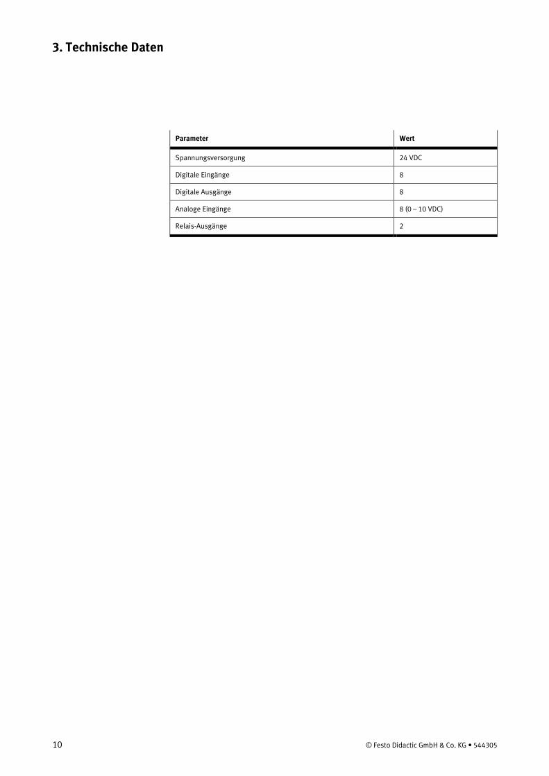
Parameter Wert
Spannungsversorgung 24 VDC
Digitale Eingänge 8
Digitale Ausgänge 8
Analoge Eingänge 8 (0 – 10 VDC)
Relais-Ausgänge 2
3. Technische Daten
© Festo Didactic GmbH & Co. KG • 544305 11
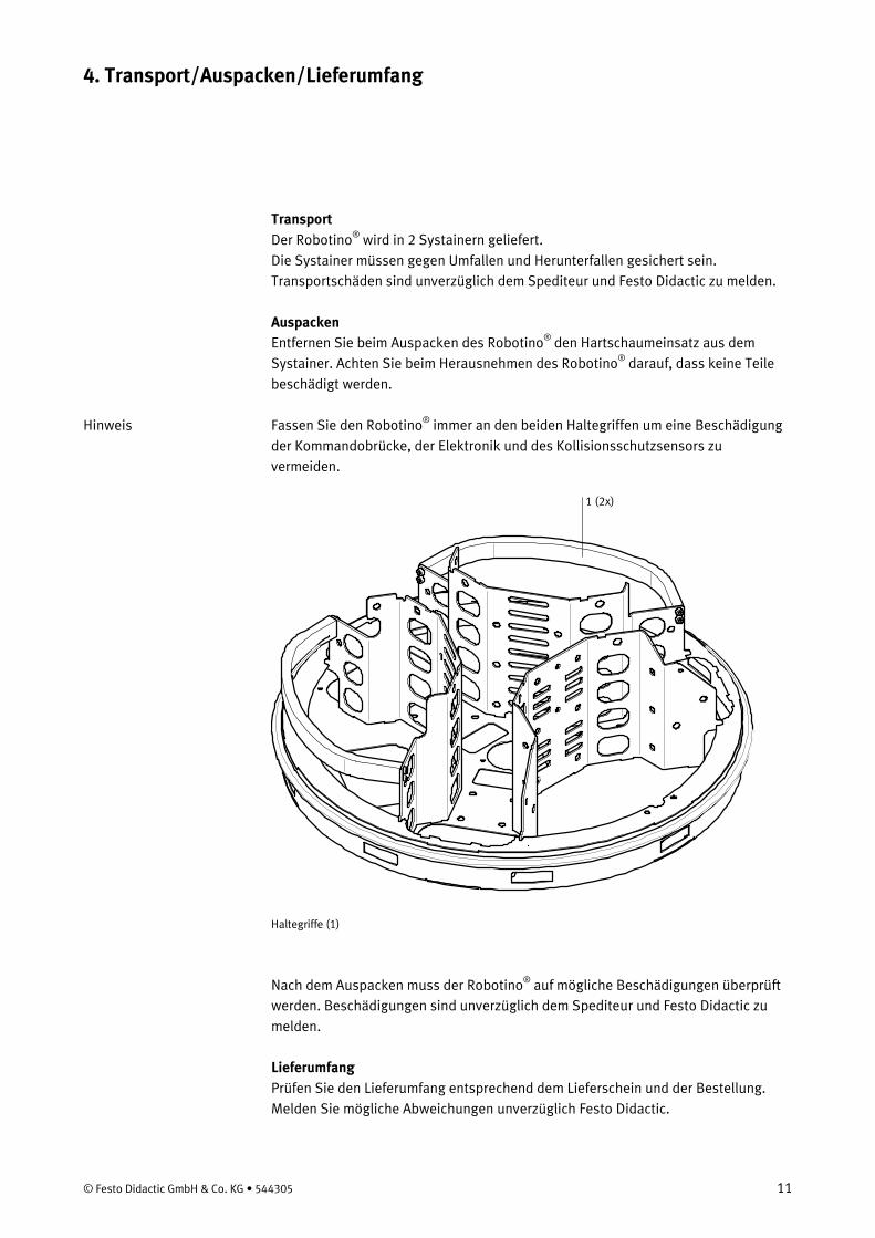
Transport Der Robotino®
wird in 2 Systainern geliefert. Die Systainer müssen gegen Umfallen und Herunterfallen gesichert sein. Transportschäden sind unverzüglich dem Spediteur und Festo Didactic zu melden.
Auspacken Entfernen Sie beim Auspacken des Robotino® den Hartschaumeinsatz aus dem Systainer. Achten Sie beim Herausnehmen des Robotino®
darauf, dass keine Teile beschädigt werden.
Fassen Sie den Robotino®
immer an den beiden Haltegriffen um eine Beschädigung der Kommandobrücke, der Elektronik und des Kollisionsschutzsensors zu vermeiden.
1 (2x)
Haltegriffe (1)
Nach dem Auspacken muss der Robotino®
auf mögliche Beschädigungen überprüft werden. Beschädigungen sind unverzüglich dem Spediteur und Festo Didactic zu melden.
Lieferumfang Prüfen Sie den Lieferumfang entsprechend dem Lieferschein und der Bestellung. Melden Sie mögliche Abweichungen unverzüglich Festo Didactic.
4. Transport/Auspacken/Lieferumfang
Hinweis
12 © Festo Didactic GmbH & Co. KG • 544305
Der Robotino® ist ein voll funktionsfähiges qualitativ hochwertiges, mobiles Robotersystem mit omnidirektionalem Antrieb. Er lässt sich über drei Antriebseinheiten in alle Richtungen bewegen und auf der Stelle drehen. Er besitzt darüber hinaus eine Webcam und mehrere Arten von Sensoren, analog zur Abstandsmessung, binär zum Beispiel für den Kollisionsschutz und digital zur Überprüfung der Ist-Geschwindigkeit. So können die vielfältigen Anforderungen an ein solches System abgedeckt werden. Der Robotino®
ist sofort und ohne PC einsetzbar.
Die Steuerung des Robotino® besteht aus einem Embedded PC mit einer Compact Flash Card, auf der mehrere Demo-Anwendungen und das Linux-Betriebssystem gespeichert sind. Die Demo-Anwendungen können direkt über das Bedienfeld des Robotino®
gestartet werden.
Die Programmierung des Robotino® kann über die Software Robotino®View von einem PC über ein Wireless LAN direkt vorgenommen werden. Mit Robotino®View können Signale an die Motorsteuerung gesendet werden, Sensorwerte angezeigt, verändert oder ausgewertet werden. Mit Robotino®View kann der Robotino®
direkt, sogar im laufenden Betrieb, programmiert werden.
Zusätzlich steht eine Linux und eine C++ API zur Verfügung, um eine Programmierung des Robotino®
vornehmen zu können.
Die Webcam ermöglicht es, mit Hilfe von Robotino®
View ein Live-Kamerabild anzuzeigen und auszuwerten. So können Anwendungen wie Bahn- oder Objektverfolgung realisiert werden.
Der Robtino®
ist autonom. Zahlreiche Sensoren, eine Kamera und eine leistungsfähige Steuerung geben dem System die notwendige „Intelligenz“.
Per Wireless LAN (WLAN) ist der direkte Zugriff auf die Steuerung möglich. Richtig programmiert löst der Robotino®
die ihm gestellten Aufgaben selbstständig.
Über eine E/A-Schnittstelle können zusätzliche Sensoren und Aktoren angeschlossen werden.
5. Aufbau und Funktion
5.1 Der Robotino®

5. Aufbau und Funktion
© Festo Didactic GmbH & Co. KG • 544305 13
Das Chassis besteht aus einer lasergeschweißten Edelstahlplattform.
1 (2x)
Haltegriffe (1)
5.2 Chassis und Kommandobrücke
5. Aufbau und Funktion
14 © Festo Didactic GmbH & Co. KG • 544305
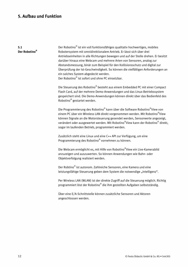
Auf diesem Chassis sind die Akkus, die Antriebseinheiten und die Kamera montiert. Dort befinden sich auch die Abstandssensoren und der Kollisionsschutzsensor. Das Chassis bietet zusätzlich Raum und Befestigungsmöglichkeiten für weitere Aufbauten, Sensoren oder Aktoren.
3 (2x)
2 (3x) Antriebseinheit (2) Batterie (3)
5. Aufbau und Funktion
© Festo Didactic GmbH & Co. KG • 544305 15
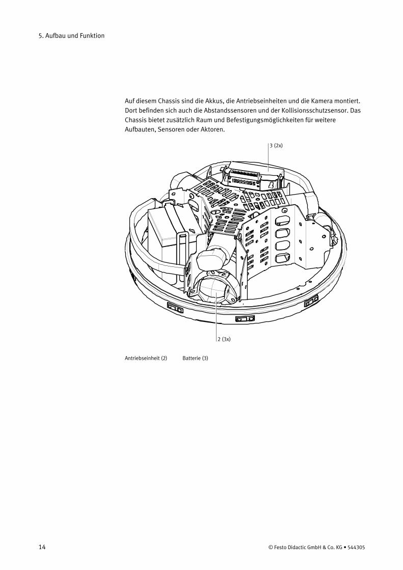
Die hochempfindlichen Elemente des Systems wie Steuerung, E/A-Modul oder die Schnittstellen befinden sich in der Kommandobrücke. Die Kommandobrücke wird durch eine Steckverbindung mit den anderen Einheiten verbunden.
4
5
Kommandobrücke (4) Kamera (5)
5. Aufbau und Funktion
16 © Festo Didactic GmbH & Co. KG • 544305
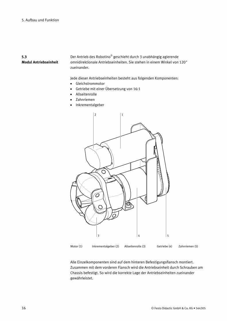
Der Antrieb des Robotino®
geschieht durch 3 unabhängig agierende omnidirektionale Antriebseinheiten. Sie stehen in einem Winkel von 120" zueinander.
Jede dieser Antriebseinheiten besteht aus folgenden Komponenten: • Gleichstrommotor • Getriebe mit einer Übersetzung von 16:1 • Allseitenrolle • Zahnriemen • Inkrementalgeber
12
3 4 5 Motor (1) Inkrementalgeber (2) Allseitenrolle (3) Getriebe (4) Zahnriemen (5)
Alle Einzelkomponenten sind auf dem hinteren Befestigungsflansch montiert. Zusammen mit dem vorderen Flansch wird die Antriebseinheit durch Schrauben am Chassis befestigt. So wird die korrekte Lage der Antriebseinheiten zueinander gewährleistet.
5.3 Modul Antriebseinheit
5. Aufbau und Funktion
© Festo Didactic GmbH & Co. KG • 544305 17
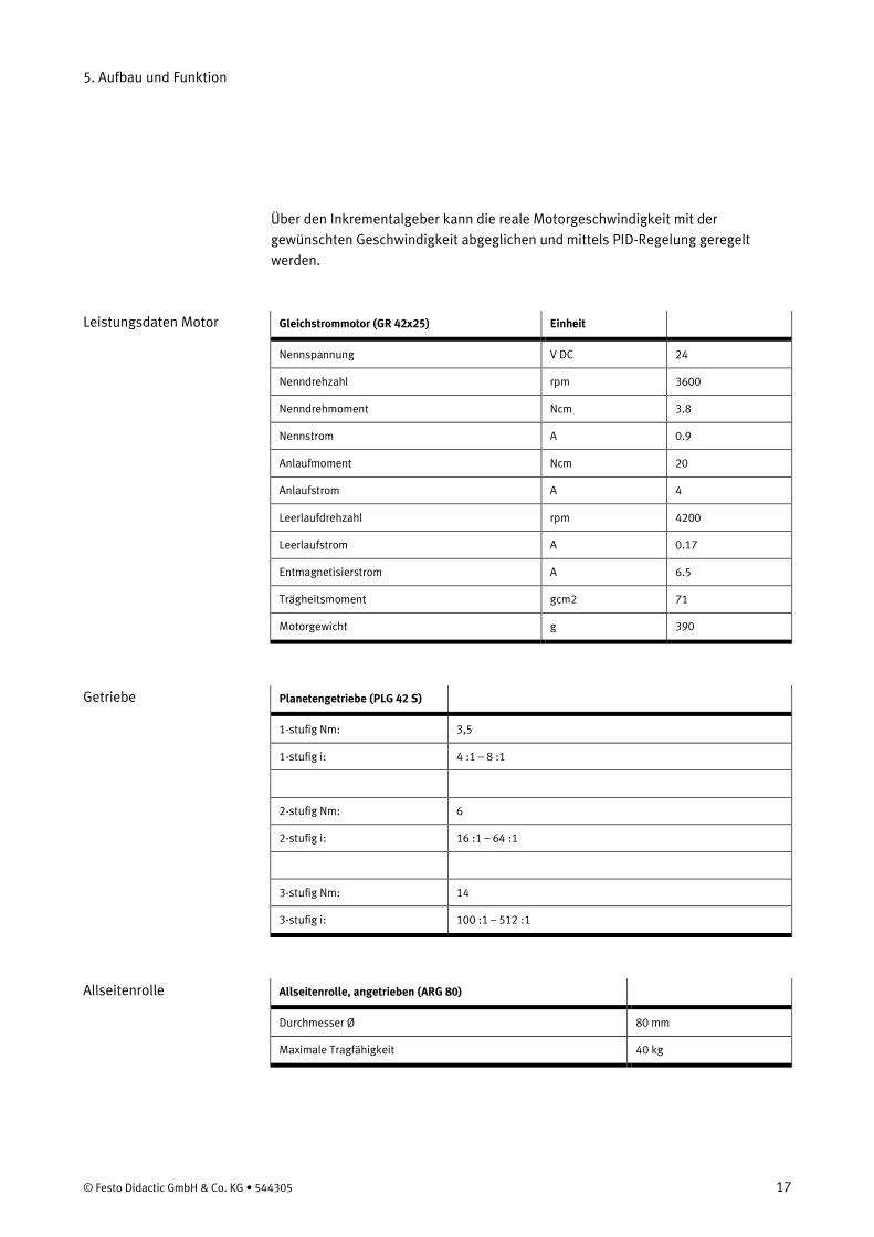
Über den Inkrementalgeber kann die reale Motorgeschwindigkeit mit der gewünschten Geschwindigkeit abgeglichen und mittels PID-Regelung geregelt werden.
Gleichstrommotor (GR 42x25) Einheit
Nennspannung V DC 24
Nenndrehzahl rpm 3600
Nenndrehmoment Ncm 3.8
Nennstrom A 0.9
Anlaufmoment Ncm 20
Anlaufstrom A 4
Leerlaufdrehzahl rpm 4200
Leerlaufstrom A 0.17
Entmagnetisierstrom A 6.5
Trägheitsmoment gcm2 71
Motorgewicht g 390
Planetengetriebe (PLG 42 S)
1-stufig Nm: 3,5
1-stufig i: 4 :1 – 8 :1
2-stufig Nm: 6
2-stufig i: 16 :1 – 64 :1
3-stufig Nm: 14
3-stufig i: 100 :1 – 512 :1
Allseitenrolle, angetrieben (ARG 80)
Durchmesser Ø 80 mm
Maximale Tragfähigkeit 40 kg
Leistungsdaten Motor
Getriebe
Allseitenrolle
5. Aufbau und Funktion
18 © Festo Didactic GmbH & Co. KG • 544305
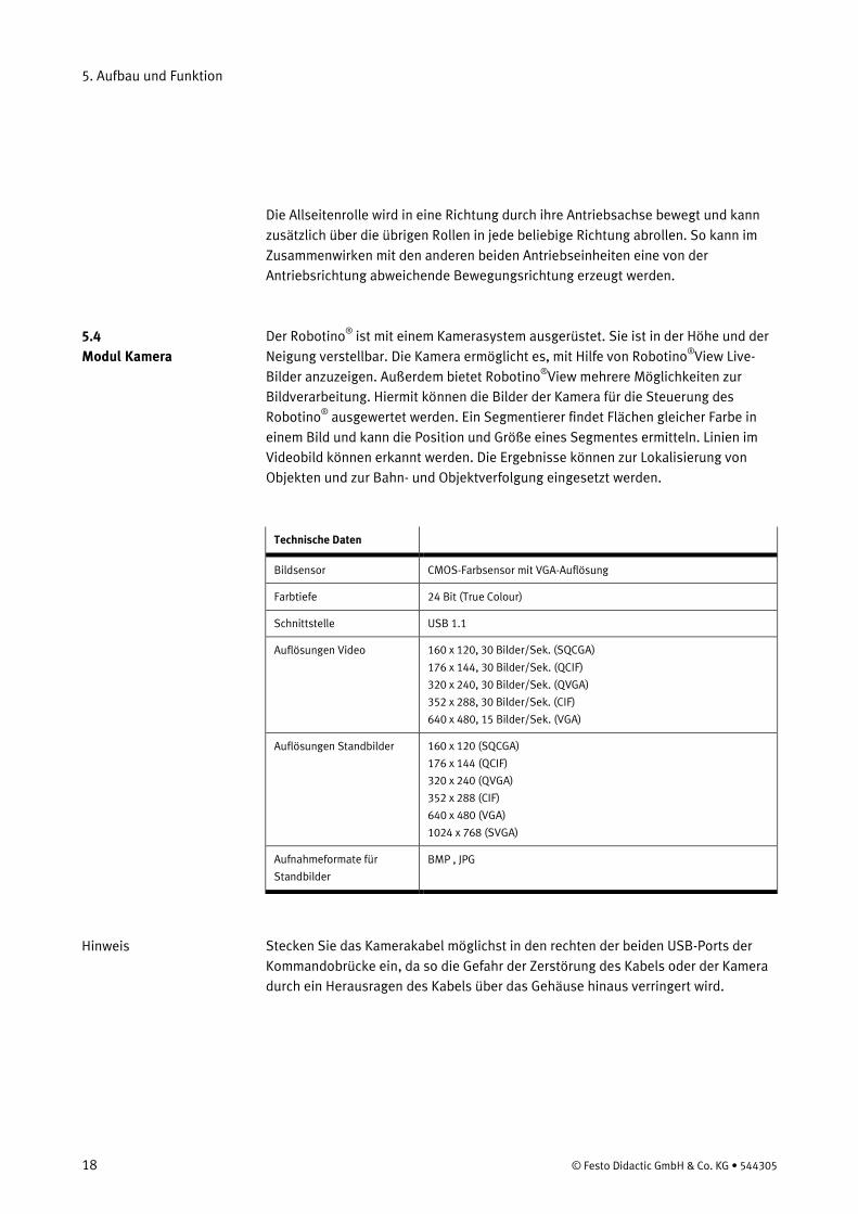
Die Allseitenrolle wird in eine Richtung durch ihre Antriebsachse bewegt und kann zusätzlich über die übrigen Rollen in jede beliebige Richtung abrollen. So kann im Zusammenwirken mit den anderen beiden Antriebseinheiten eine von der Antriebsrichtung abweichende Bewegungsrichtung erzeugt werden. Der Robotino® ist mit einem Kamerasystem ausgerüstet. Sie ist in der Höhe und der Neigung verstellbar. Die Kamera ermöglicht es, mit Hilfe von Robotino®View Live-Bilder anzuzeigen. Außerdem bietet Robotino®View mehrere Möglichkeiten zur Bildverarbeitung. Hiermit können die Bilder der Kamera für die Steuerung des Robotino®
ausgewertet werden. Ein Segmentierer findet Flächen gleicher Farbe in einem Bild und kann die Position und Größe eines Segmentes ermitteln. Linien im Videobild können erkannt werden. Die Ergebnisse können zur Lokalisierung von Objekten und zur Bahn- und Objektverfolgung eingesetzt werden.
Technische Daten
Bildsensor CMOS-Farbsensor mit VGA-Auflösung
Farbtiefe 24 Bit (True Colour)
Schnittstelle USB 1.1
Auflösungen Video 160 x 120, 30 Bilder/Sek. (SQCGA)
176 x 144, 30 Bilder/Sek. (QCIF)
320 x 240, 30 Bilder/Sek. (QVGA)
352 x 288, 30 Bilder/Sek. (CIF)
640 x 480, 15 Bilder/Sek. (VGA)
Auflösungen Standbilder 160 x 120 (SQCGA)
176 x 144 (QCIF)
320 x 240 (QVGA)
352 x 288 (CIF)
640 x 480 (VGA)
1024 x 768 (SVGA)
Aufnahmeformate für
Standbilder
BMP , JPG
Stecken Sie das Kamerakabel möglichst in den rechten der beiden USB-Ports der Kommandobrücke ein, da so die Gefahr der Zerstörung des Kabels oder der Kamera durch ein Herausragen des Kabels über das Gehäuse hinaus verringert wird.
5.4 Modul Kamera
Hinweis
5. Aufbau und Funktion
© Festo Didactic GmbH & Co. KG • 544305 19
Die Steuerungseinheit ist flexibel aus mehreren Karten aufgebaut. Die im Robotino®
– PC 104 Prozessor kompatibel zum MOPSlcdVE mit 300 MHz und Linux Betriebssystem mit Echtzeitkernel, SDRAM 128 MB
eingebaute Steuerungseinheit besteht aus 3 Komponenten:
– Compact Flash Karte (256 MB) mit C++ API zur Ansteuerung von Robotino®
– Wireless LAN Access-Point
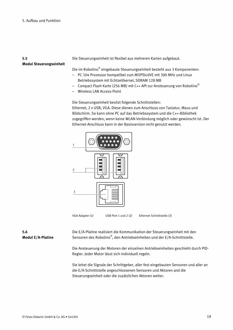
Die Steuerungseinheit besitzt folgende Schnittstellen: Ethernet, 2 x USB, VGA. Diese dienen zum Anschluss von Tastatur, Maus und Bildschirm. So kann ohne PC auf das Betriebssystem und die C++-Bibliothek zugegriffen werden, wenn keine WLAN-Verbindung möglich oder gewünscht ist. Der Ethernet-Anschluss kann in der Basisversion nicht genutzt werden.
1
2
3
VGA-Adapter (1) USB Port 1 und 2 (2) Ethernet-Schnittstelle (3)
Die E/A-Platine realisiert die Kommunikation der Steuerungseinheit mit den Sensoren des Robotino®
, den Antriebseinheiten und der E/A-Schnittstelle.
Die Ansteuerung der Motoren der einzelnen Antriebseinheiten geschieht durch PID-Regler. Jeder Motor lässt sich individuell regeln. Sie leitet die Signale der Schrittgeber, aller fest eingebauten Sensoren und aller an die E/A-Schnittstelle angeschlossenen Sensoren und Aktoren and die Steuerungseinheit oder die zusätzlichen Aktoren weiter.
5.5 Modul Steuerungseinheit
5.6 Modul E/A-Platine
5. Aufbau und Funktion
20 © Festo Didactic GmbH & Co. KG • 544305
Die Energieversorgung geschieht durch zwei aufladbare 12V Akkus mit 4Ah gewährleistet. Beide Akkus sind auf dem Chassis untergebracht. Der Robotino®
wird mit 2 zusätzlichen Akkus und einem Ladegerät geliefert. So können immer zwei Akkus geladen werden, während die anderen beiden im Einsatz sind.
Im Robotino®
sind Sensoren für die Messung des Abstands von Objekten und der Geschwindigkeit des Motors integriert. Ein Kollisionsschutzsensor um das Chassis meldet die Berührung eines Objektes.
Der Robotino® besitzt 9 Infrarot-Abstandssensoren, die in einem Winkel von 40° zueinander im Chassis untergebracht sind. Mit diesen Sensoren kann das gesamte Umfeld des Robotino®
nach Objekten untersucht werden. Jeder dieser Sensoren kann über die E/A-Platine individuell abgefragt werden. So kann Hindernissen ausgewichen werden, Abstand gehalten oder ein Ziel angesteuert werden. Der Sensor ermöglicht genaue oder relative Abstandsmessungen eines Objekts zwischen 4 und 30 cm. Seine Besonderheit ist sein einfache Anschluss, der nur aus Stromversorgung und einem analogen Ausgangssignal besteht. Seine Auswertelektronik misst die Entfernung und gibt sie über ein Analogsignal aus.
Mit dem Inkrementalgeber wirt die tatsächliche Drehzahl jedes einzelnen Motors gemessen. Über eine PID-Regelung, deren Parameter in der Software Robotino®
View eingestellt werden können, kann die jeweilige Ist-Geschwindigkeit an die Sollgeschwindigkeit angeglichen werden, falls diese unterschiedlich zur Sollgeschwindigkeit sind.
Der Kollisionsschutzsensor ist eine Schaltleiste, die um das gesamte Chassis herum befestigt ist. In einem Kunststoff-Profil befindet sich eine Schaltkammer. Dort befinden sich 2 voneinander getrennte leitfähige Bereiche. Diese werden schon bei geringem Druck auf das Kunststoff-Profil kurzgeschlossen. So entsteht ein sicher erkennbares Signal an die Steuerungseinheit. Eine Kollision mit einem Objekt an jeder Stelle des Gehäuses kann erkannt werden und beispielsweise die Bewegung des Robotino®
gestoppt werden.
5.7 Energieversorgung / Ladegerät
5.8 Sensoren
Infrarot Abstandssensor
Inkrementalgeber
Kollisionsschutzsensor
5. Aufbau und Funktion
© Festo Didactic GmbH & Co. KG • 544305 21
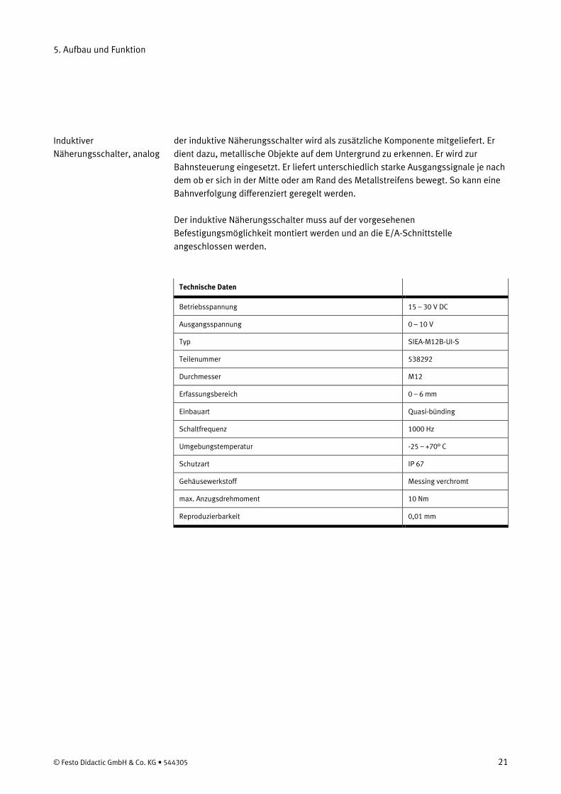
der induktive Näherungsschalter wird als zusätzliche Komponente mitgeliefert. Er dient dazu, metallische Objekte auf dem Untergrund zu erkennen. Er wird zur Bahnsteuerung eingesetzt. Er liefert unterschiedlich starke Ausgangssignale je nach dem ob er sich in der Mitte oder am Rand des Metallstreifens bewegt. So kann eine Bahnverfolgung differenziert geregelt werden. Der induktive Näherungsschalter muss auf der vorgesehenen Befestigungsmöglichkeit montiert werden und an die E/A-Schnittstelle angeschlossen werden.
Technische Daten
Betriebsspannung 15 – 30 V DC
Ausgangsspannung 0 – 10 V
Typ SIEA-M12B-UI-S
Teilenummer 538292
Durchmesser M12
Erfassungsbereich 0 – 6 mm
Einbauart Quasi-bünding
Schaltfrequenz 1000 Hz
Umgebungstemperatur -25 – +70° C
Schutzart IP 67
Gehäusewerkstoff Messing verchromt
max. Anzugsdrehmoment 10 Nm
Reproduzierbarkeit 0,01 mm
Induktiver Näherungsschalter, analog
5. Aufbau und Funktion
22 © Festo Didactic GmbH & Co. KG • 544305
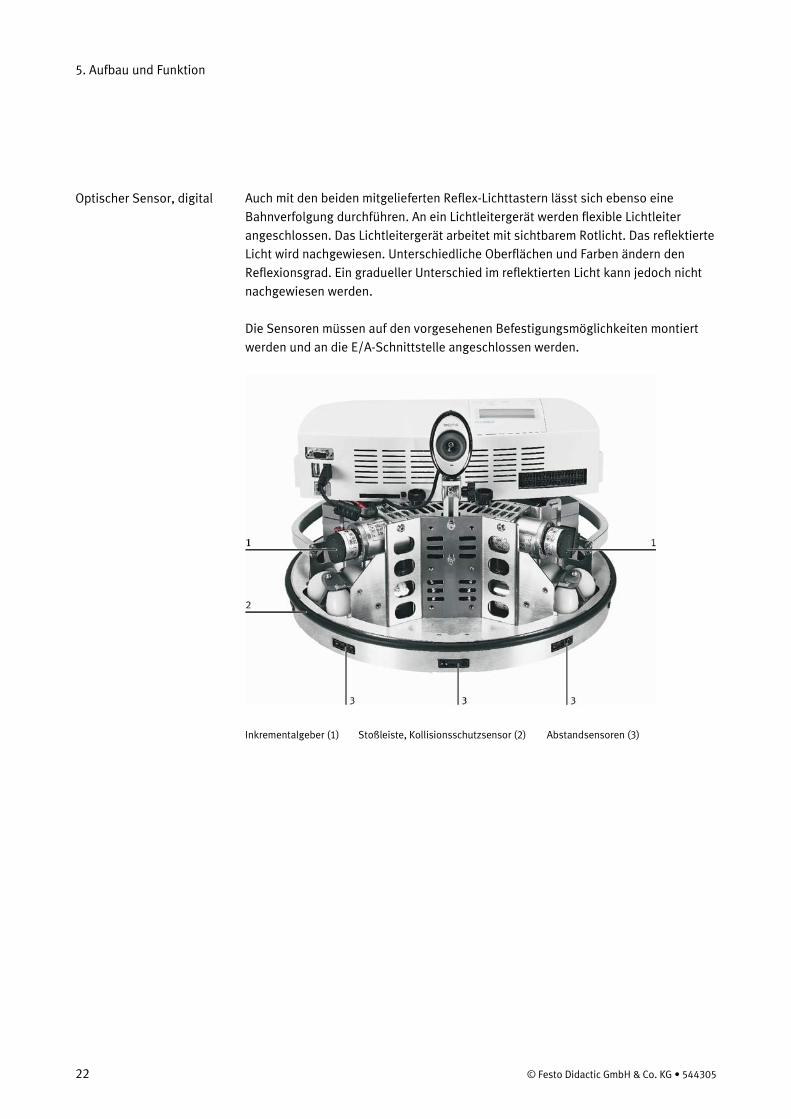
Auch mit den beiden mitgelieferten Reflex-Lichttastern lässt sich ebenso eine Bahnverfolgung durchführen. An ein Lichtleitergerät werden flexible Lichtleiter angeschlossen. Das Lichtleitergerät arbeitet mit sichtbarem Rotlicht. Das reflektierte Licht wird nachgewiesen. Unterschiedliche Oberflächen und Farben ändern den Reflexionsgrad. Ein gradueller Unterschied im reflektierten Licht kann jedoch nicht nachgewiesen werden. Die Sensoren müssen auf den vorgesehenen Befestigungsmöglichkeiten montiert werden und an die E/A-Schnittstelle angeschlossen werden.
Inkrementalgeber (1) Stoßleiste, Kollisionsschutzsensor (2) Abstandsensoren (3)
Optischer Sensor, digital
5. Aufbau und Funktion
© Festo Didactic GmbH & Co. KG • 544305 23
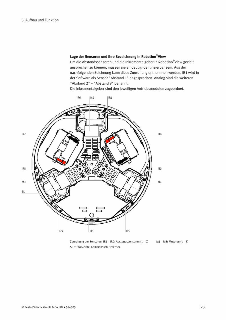
Lage der Sensoren und ihre Bezeichnung in Robotino®
Um die Abstandssensoren und die Inkrementalgeber in RobotinoView
®
View gezielt ansprechen zu können, müssen sie eindeutig identifizierbar sein. Aus der nachfolgenden Zeichnung kann diese Zuordnung entnommen werden. IR1 wird in der Software als Sensor "Abstand 1" angesprochen. Analog sind die weiteren "Abstand 2" – "Abstand 9" benannt. Die Inkrementalgeber sind den jeweiligen Antriebsmodulen zugeordnet.
IR6 IR5M2
IR4
IR3
M1
IR9 IR1 IR2
IR3
M3
IR8
SL
IR7
Zuordnung der Sensoren, IR1 – IR9: Abstandssensoren (1 – 9) M1 – M3: Motoren (1 – 3)
SL = Stoßleiste, Kollisionsschutzsensor
5. Aufbau und Funktion
24 © Festo Didactic GmbH & Co. KG • 544305
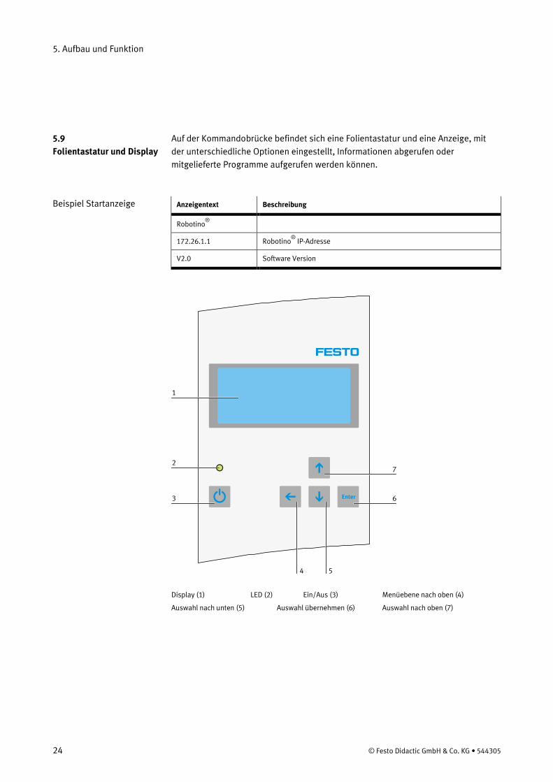
Auf der Kommandobrücke befindet sich eine Folientastatur und eine Anzeige, mit der unterschiedliche Optionen eingestellt, Informationen abgerufen oder mitgelieferte Programme aufgerufen werden können.
Anzeigentext Beschreibung
Robotino ®
172.26.1.1 Robotino®
V2.0
IP-Adresse
Software Version
Enter
1
2
3 6
7
54 Display (1) LED (2) Ein/Aus (3) Menüebene nach oben (4)
Auswahl nach unten (5) Auswahl übernehmen (6) Auswahl nach oben (7)
5.9 Folientastatur und Display
Beispiel Startanzeige
5. Aufbau und Funktion
© Festo Didactic GmbH & Co. KG • 544305 25
Der Wireless LAN Accesspoint ist eine Komponente, die dazu dient, mit dem Roboter über eine Netzwerkadresse kommunizieren zu können. – Der Accesspoint hat einen niedriger Stromverbrauch. Eine Stromversorgung über
USB ist möglich. – Er entspricht den Normen IEEE 802.11g und 802.11b Standard – Er ermöglicht Datenraten bis zu 54Mbps für 802-11g und 11Mbps für 802.11b
mit hoher Reichweite (in Gebäuden bis zu 100m) – Er bietet eine große Netzwerksicherheit durch WEP-Verschlüsselung und WPA-
PSK Funktion – Er ist schnell und einfach über die Web-Management Utility zu konfigurieren Die Steuerungseinheit ist mit einem PC Card-Steckplatz ausgerüstet, in die eine PC Card eingesteckt ist. Auf dieser PC-Card befinden sich das Betriebssystem, die Funktionsbibliotheken und die mitgelieferten Programme. Updates können problemlos durchgeführt werden, indem einfach die PC-Card ausgewechselt wird. Der Steckplatz für die PC-Card befindet sich rechts neben den Schnittstellen der Steuerungseinheit. Updates können Sie kostenlos von unserer Homepage auf Ihre bestehende Speicherkarte laden.
5.10 Wireless LAN Accesspoint
5.11 Compact Flash Karte
5. Aufbau und Funktion
26 © Festo Didactic GmbH & Co. KG • 544305
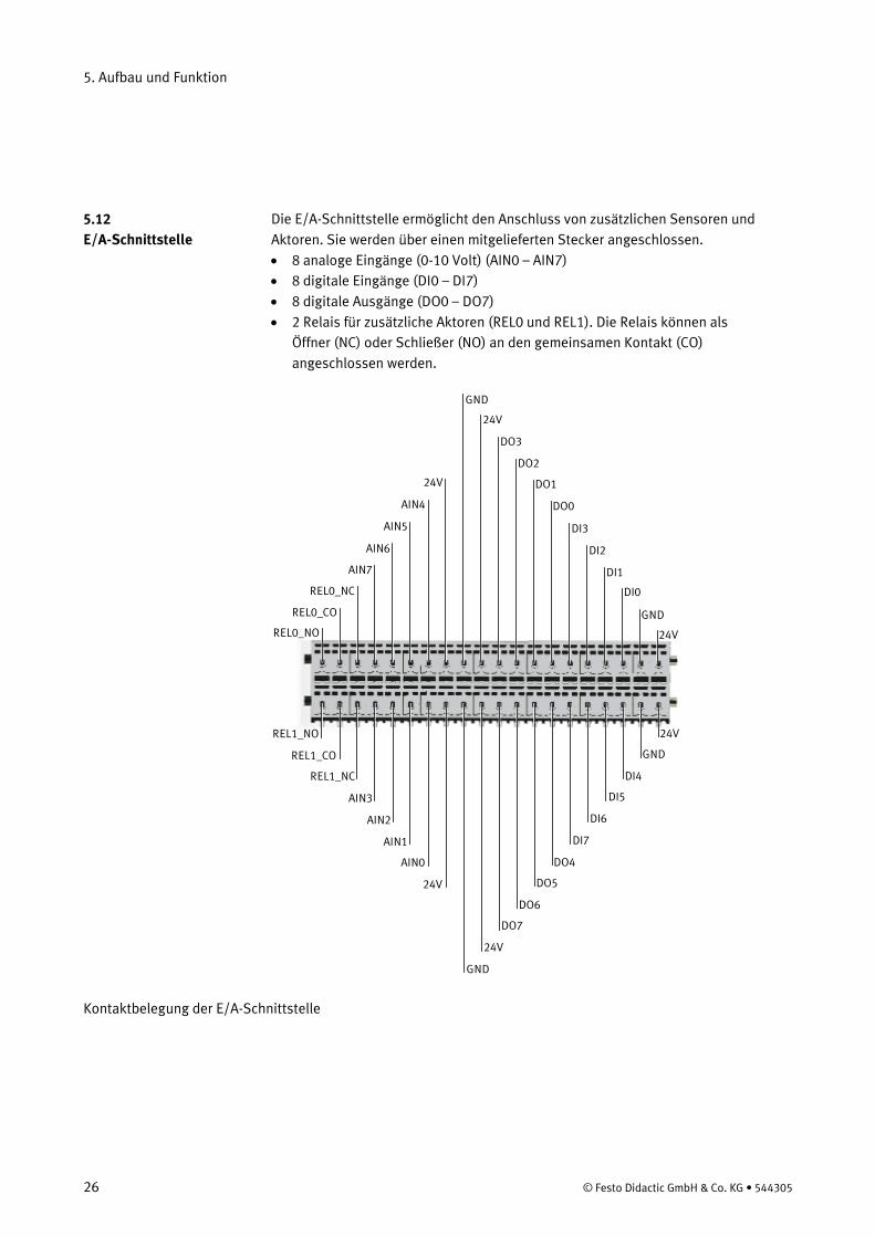
Die E/A-Schnittstelle ermöglicht den Anschluss von zusätzlichen Sensoren und Aktoren. Sie werden über einen mitgelieferten Stecker angeschlossen. • 8 analoge Eingänge (0-10 Volt) (AIN0 – AIN7) • 8 digitale Eingänge (DI0 – DI7) • 8 digitale Ausgänge (DO0 – DO7) • 2 Relais für zusätzliche Aktoren (REL0 und REL1). Die Relais können als
Öffner (NC) oder Schließer (NO) an den gemeinsamen Kontakt (CO) angeschlossen werden.
DO2
24V
24V
DI0
DI2
GND
DI1
DI3
DO0
DO124V
AIN5
AIN7
AIN4
AIN6
REL0_NC
REL0_CO
REL0_NO
DO3
GND
DO6
24V
24V
DI4
DI6
GND
DI5
DI7
DO4
DO524V
AIN1
AIN3
AIN0
AIN2
REL1_NC
REL1_CO
REL1_NO
DO7
GND
Kontaktbelegung der E/A-Schnittstelle
5.12 E/A-Schnittstelle
© Festo Didactic GmbH & Co. KG • 544305 27
Wenn Sie nicht mit dem Robotino® arbeiten oder einzelne Funktionen testen möchten, bocken Sie den Robotino® immer auf! Sie können dann bequem die Funktion von Sensoren überprüfen oder Aktoren ansteuern ohne eine Kollision befürchten zu müssen. Der Robotino®
bleibt dabei immer in Ihrer Nähe und kann an die Ladestation angeschlossen bleiben.
Mit der mitgelieferten Vorrichtung können Sie den Robotino® so aufbocken, dass die Räder des Robotino® frei beweglich sind und keinen Kontakt zum Untergrund besitzen. Legen Sie hierzu die Aufbockvorrichtung auf eine stabile und ebene Fläche. Stellen Sie den Robotino® dann auf die Gummipuffer. Sie müssen den Robotino®
so auf der Aufbockvorrichtung platzieren, dass sich auch die Ritzel der Antriebe frei bewegen können.
Transportieren Sie den Robotino® immer indem Sie ihn an den Haltegriffen greifen. Ein Anheben an der Kommandobrücke kann die empfindliche Elektronik beschädigen. Vorne ist beim Robotino®
dort, wo sich der Abstandssensor 1 und die Befestigungsmöglichkeit für den induktiven Sensor befindet.
Hindernisse müssen bis auf den Untergrund reichen, da sonst der Kollisionsschutzsensor nicht anspricht. Das gleiche gilt für die Abstandssensoren. Dies ist wichtig, da sonst eine Beschädigung des Robotino®
entstehen kann.
Schließen Sie als nächstes das Ladegerät an das entsprechende Kabel der Batterien an. Das Kabel befindet hinter der Antriebseinheit M1. Der Stecker liegt unter dem Ring der Bodengruppe. Ziehen Sie diesen vorsichtig heraus und schließen Sie ihn an das Ladegerät an. Stecken Sie hierzu den Stecker in die Buchse ein. Achten Sie hierbei darauf, dass die Rastklemme des Kabels vom Ladegerät einrastet. Zum Lösen der Kabelverbindung muss die Rastklemme gedrückt und gleichzeitig der Stecker herausgezogen werden. Schalten Sie nun den Robotino®
Nun bootet die Steuerungseinheit des Robotino
ein. Drücken Sie den Einschaltknopf, bis die LED aufleuchtet. Das Display schaltet sich ein. Auf der Anzeige werden 2 Balken über die ganze Breite der Anzeige angezeigt.
Nach ca. 30 Sekunden erscheint im Display die Startanzeige.
®
Die Anzeige lautet zum Beispiel: Robotino 172.26.1.1
®
6. Inbetriebnahme
6.1 Erste Schritte
Wichtige Hinweise
6.2 Ein- und Ausschalten
6. Inbetriebnahme
28 © Festo Didactic GmbH & Co. KG • 544305
In der letzten Zeile befindet sich eine Balkenanzeige des Ladezustands der Batterien und die Anzeige der Robotino®
-Version: V 1.0
Jetzt ist der Robotino®
betriebsbereit.
Falls 10 Sekunden lang keine Taste betätigt wird, schaltet sich die Beleuchtung der Anzeige ab, um den Stromverbrauch im Betrieb möglichst gering zu halten. Um sie wieder zu aktivieren, drücken Sie bitte eine der Pfeiltasten um sie wieder einzuschalten. Drücken Sie hierzu nicht die Enter-Taste um einen ungewollten Start zum Beispiel eines Demoprogramms zu vermeiden! Ausschalten Drücken Sie den Ein / Ausschaltknopf bis die LED erlischt. Anschließend müssen Sie die Taste loslassen. Der Robotino®
ist erst abgeschaltet, wenn die Taste losgelassen wird.
Hauptmenü Durch Drücken der Enter-Taste gelangen Sie in das Hauptmenü. Die Anzeige ist in ihrem Ursprungszustand in englischer Sprache. Das Hauptmenu enthält die folgenden Menüpunkte: • Sprachen • Ladezustand • DEMOs • Netzwerk Mit den Tasten Pfeil nach oben oder Pfeil nach unten bewegen Sie die Markierung am linken Rand der Anzeige (>) auf- oder abwärts. Durch Drücken der Entertaste wird der jeweilige Menüeintrag aufgerufen oder das markierte Demo-Programm gestartet. Durch Drücken der Taste Pfeil nach links verlassen sie ein Menü zum jeweils nächst höheren Menü. Stellen Sie zuerst die Sprache der Menus auf deutsch um. Wählen Sie den Menupunkt "languages"
Hinweis
6.3 Die Funktionen der Anzeige
6. Inbetriebnahme
© Festo Didactic GmbH & Co. KG • 544305 29
Languages deutsch english français español Bewegen Sie die Markierung auf "german". Betätigen Sie die Entertaste . Verlassen Sie das Menu mit der Taste Pfeil nach oben. Die Menus werden ab jetzt in deutscher Sprache angezeigt. Ladezustand Dieser Menupunkt informiert sie mit einer Balkenanzeige über den Ladezustand und die Spannung der beiden Batterien. ,Zusätzlich wird die aktuell verbrauchte Strom angezeigt. Spannung: 23 V Strom : 1.0 A DEMOs In diesem Menu können Sie eines der Demoprogramme auswählen Kreis Vorwärts Viereck Erkunden Linie folgen Netzwerk In diesem Menü wird die aktuelle IP-Adresse angezeigt und kann geändert werden. Mit der Enter-Taste wird der Cursor (Pfeilspitze) nach rechts und mit der Pfeil nach links Taste nach links bewegt. Mit den Pfeil nach oben / unten Tasten kann der Wert der einzelnen Zahlen vergrößert oder verkleinert werden. Um das Menü wieder zu verlassen, fahren Sie mit der Pfeil nach links-Taste zur ersten Ziffer. Durch ein weiteres Drücken der Pfeil nach links Taste erreichen Sie wieder das Hauptmenü. Durch ein weiteres Drücken der Enter-Taste an der letzten Ziffer der IP-Adresse gelangen Sie zur nächsten Anzeige, der Subnet-Maske. Verfahren Sie wie bei der IP-Adresse. Befinden Sie sich auf der letzten Ziffer der Subnet-Maske, werden Ihre Änderungen an der IP-Adresse und der Subnet-Maske durch erneutes Drücken der Enter-Taste übernommen.
6. Inbetriebnahme
30 © Festo Didactic GmbH & Co. KG • 544305
Überprüfen Sie zuerst die Funktion der Demoprogramme im aufgebockten Zustand um sich mit ihren Funktionen vertraut zu machen. Wählen Sie ein Demo-Programm aus und starten Sie es indem Sie die Entertaste drücken. Stoppen Sie die Programme durch kurzes Drücken einer beliebigen Taste der Folientastatur oder durch Drücken der Stoßleiste. In beiden Fällen bleibt der Robotino®
sofort stehen.
Die Programme Kreis und Vorwärts haben eine zeitliche Begrenzung, sie stoppen den Robotino®
nach 10 Sekunden selbsttätig.
Kreis Der Robotino®
fährt eine Kreisbahn Benötigter Platz: Ein Rechteck von der Größe 1m x 1m Zeitliche Begrenzung: 10 s Programm beenden: Siehe oben
Vorwärts Der Robotino®
fährt geradeaus vorwärts Benötigter Platz: Eine gerade Strecke von 1 m Zeitliche Begrenzung: 10 s Programm beenden: Siehe oben
Viereck Der Robotino®
fährt ein Rechteck und dreht sich um die eigene Achse 1 m x 1m Zeitliche Begrenzung: Keine Programm beenden: Siehe oben
Erkunden Der Robotino® fährt geradeaus und weicht vorhandenen Hindernissen aus. Je nach Lage der Hindernisse ändert der Robotino®
seine Fahrtrichtung auf unterschiedliche Weise. Benötigter Platz: Beliebig Zeitliche Begrenzung: keine Programm beenden: Siehe oben.
Zur Erkennung von Hindernissen werden die Abstandssensoren 1, 2 und 9 eingesetzt. Daher ist das Stoppen des Programms durch die Stoßleiste im Erfassungsbereich dieser Sensoren nicht möglich, da der Robotino®
ausweicht.
6.4 Testen der Demoprogramme
Bemerkung
6. Inbetriebnahme
© Festo Didactic GmbH & Co. KG • 544305 31
Linie folgen Für dieses Programm muss die Kamera des Robotino über die USB-Schnittstelle mit der Steuerungseinheit verbunden sein. Zeichnen Sie eine mindestens 5 cm breite Linie, zum Beispiel mit Klebeband, auf dem Untergrund. Die Linie muss in roter, schwarzer oder blauer Farbe sein. Setzen Sie den Robotino® so auf die Linie, dass er die Linie erkennen kann, und starten Sie das Programm. Der Robotino®
Der Untergrund, auf dem der Robotino
folgt der markierten Linie.
®
Je nach Bodenbeschaffenheit kann der oben angegebene Platzbedarf variieren. Wählen Sie deshalb eine ausreichend große freie Fläche. Der oben angegebene Platzbedarf ist eine Mindestangabe.
fahren soll, muss waagrecht und eben sein. So können die gewünschten Bewegungen sicher ausgeführt werden. Um Beschädigungen der mechanischen und der elektronischen Bauteile zu vermeiden, muss der Untergrund sauber und trocken sein. Lösen Sie unbedingt das Kabel des Ladegeräts, bevor Sie ein Programm starten und verstauen Sie das Kabel wieder im Chassis.
Robotino kann u.a. grafisch mit RobotinoView programmiert werden. Zum Einstieg in RobotinoView empfehlen wir, die installierten Beispiel-Programme zu nutzen. Zu jedem Funktionsbaustein finden Sie in der Kontext-Hilfe von RobotinoView weitere Informationen und Beispiele. Ab Version 2.0 können Sie RobotinoView Programme (Dateiendung .rvw2) per Mausklick auf Robotino übertragen und ausführen. Robotino wird somit zum autonomen Roboter Bitte achten Sie darauf stets die aktuelle Version von RobotinoView auf Ihrem PC und Robotino (Speicherkarte) installiert zu haben. Um den Robotino® mit Robotino®View steuern zu können, muss eine WLAN-Verbindung hergestellt werden. Da unterschiedliche WLAN Hardware und Software existiert, kann hier auf die korrekte Einrichtung und Bereitstellung Ihres WLANs nicht im Detail eingegangen werden. Aktivieren Sie Ihr WLAN. Ihre WLAN Einstellung muss es ermöglichen, dass dem WLAN eine IP-Adresse zugewiesen wird. Nur so kann der Accesspoint im Robotino®
Stellen Sie sicherheitshalber den Robotino
mit Ihrem Netzwerk eine Verbindung herstellen.
® auf die Aufbockvorrichtung. Schalten Sie dann den Robotino®
6.5 Ausführen der Demoprogramme auf festem Untergrund
ein und warten Sie den Bootvorgang ab. Sie erkennen dies am Display. Notieren Sie die angezeigte IP-Adresse. Zur Sicherheit befindet sich auf der Unterseite der Kommandobrücke ein Aufkleber mit der IP-Adresse und der Nummer des WLAN-Kanals.
Hinweise
6.6 Steuern des Robotino® mit Robotino®
6.7 Einrichten einer WLAN-Verbindung
View
6. Inbetriebnahme
32 © Festo Didactic GmbH & Co. KG • 544305
Lassen Sie Ihr WLAN nach verfügbaren Netzwerken suchen. Ein Netzwerk mit dem Namen Robotino®
x.x erscheint nun in der Liste der verfügbaren Netzwerke. Stellen Sie gegebenenfalls eine Verbindung mit diesem Netzwerk her, falls dies nicht von Ihrer Netzwerksoftware aus geschehen ist.
Voraussetzung für eine erfolgreiche Verbindung sind die folgende Einstellungen Ihres Netzwerks: Netzwerkschlüssel (SSID) automatisch zuweisen IP-Adresse automatisch beziehen Beide Einstellungen müssen eingeschaltet sein, damit eine Verbindung vom Robotino®
hergestellt werden kann.
Sie können die WLAN-Verbindung mit 2 einfachen DOS-Befehlen oder der Software Robotino®
View überprüfen.
Der Befehl ping IP-Adresse Starten Sie die MS-DOS Eingabeaufforderung. Sie befindet sich im Startmenü unter Programme/Zubehör. Klicken Sie auf "Eingabeaufforderung". Alternativ können Sie im Startmenü unter Ausführen...den Befehl "cmd" eingeben. Geben Sie nun an der Eingabeaufforderung ">" den Befehl "ping" mit der IP-Adresse, die Sie vom Robotino®
-Display abgelesen haben, ein. Zum Beispiel "ping 172.26.1.1"
Besteht eine WLAN-Verbindung erhalten Sie folgende Meldungen: C:\>ping 172.26.1.1 Ping wird ausgeführt für 172.26.1.1 mit 32 Bytes Daten: Antwort von 172.26.1.1: Bytes=32 Zeit=4ms TTL=64 Antwort von 172.26.1.1: Bytes=32 Zeit=2ms TTL=64 Antwort von 172.26.1.1: Bytes=32 Zeit=3ms TTL=64 Antwort von 172.26.1.1: Bytes=32 Zeit=6ms TTL=64 Ping-Statistik für 172.26.1.1: Pakete: Gesendet = 4, Empfangen = 4, Verloren = 0 (0% Verlust), Ca. Zeitangaben in Millisek.: Minimum = 2ms, Maximum = 6ms, Mittelwert = 3ms Besteht keine Verbindung zum Robotino®
erhalten Sie die folgende Meldung:
Ping wird ausgeführt für 172.26.1.1 mit 32 Bytes Daten:
6.8 Prüfen der WLAN-Verbindung
6. Inbetriebnahme
© Festo Didactic GmbH & Co. KG • 544305 33
Zeitüberschreitung der Anforderung. Zeitüberschreitung der Anforderung. Zeitüberschreitung der Anforderung. Zeitüberschreitung der Anforderung. Ping-Statistik für 172.26.1.1: Pakete: Gesendet = 4, Empfangen = 0, Verloren = 4 (100% Verlust), Der Befehl ipconfig /all Mit diesem Befehl können Sie die Einstellungen und Zustände aller Ihrer Netzwerkverbindungen überprüfen. Starten Sie die MS-DOS Eingabeaufforderung. Sie befindet sich im Startmenü unter Programme/Zubehör. Klicken Sie auf "Eingabeaufforderung". Alternativ können Sie im Startmenü unter Ausführen...den Befehl "cmd" eingeben. Geben Sie an der Eingabeaufforderung ">" den Befehl "ipconfig /all" ein und drücken Sie die Eingabetaste. Ist eine Verbindung zum Robotino®
hergestellt, erhalten Sie folgende Informationen. Je nach Typ Ihres WLAN-Netzwerks sind hier jedoch Unterschiede möglich. Suchen Sie unter den verschiedenen Netzwerkeinstellungen die Einstellungen für "Wireless Network Connection". Die angezeigten Informationen können beispielsweise folgendermaßen aussehen:
Ethernetadapter Wireless Network Connection: Verbindungsspezifisches DNS-Suffix: Beschreibung .......................... : Dell Wireless 1470 Dual Band WLAN Mini-PCI Karte Physikalische Adresse............. : 00-14-A5-44-A4-D6 DHCP aktiviert ......................... : Ja Autokonfiguration aktiviert ..... : Ja IP-Adresse ............................... : 72.26.201.1 Subnetzmaske ........................ : 255.255.0.0 Standardgateway .................... : DHCP-Server ........................... : 172.26.101.8 Lease erhalten ........................ : Freitag, 17. Februar 2006 13:51:14 Lease läuft ab.......................... : Freitag, 24. Februar 2006 13:51:14
6. Inbetriebnahme
34 © Festo Didactic GmbH & Co. KG • 544305
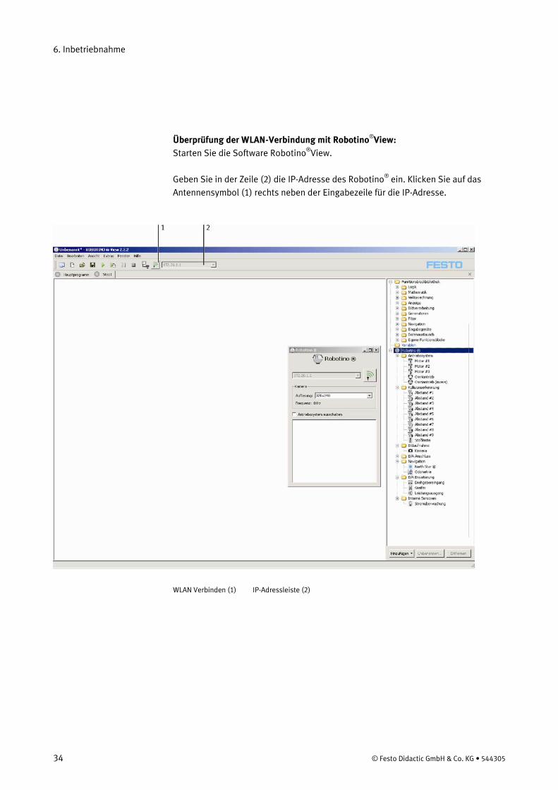
Überprüfung der WLAN-Verbindung mit Robotino®
Starten Sie die Software RobotinoView:
®
View.
Geben Sie in der Zeile (2) die IP-Adresse des Robotino®
ein. Klicken Sie auf das Antennensymbol (1) rechts neben der Eingabezeile für die IP-Adresse.
WLAN Verbinden (1) IP-Adressleiste (2)
6. Inbetriebnahme
© Festo Didactic GmbH & Co. KG • 544305 35
Besteht keine Verbindung zum Robotino®
Ist der Verbindungsaufbau erfolgreich, können Sie direkt auf alle Funktionen der Software und alle Einheiten des Robotino
wird nach einer gewissen Zeit (45 sek) eine Meldung ausgegeben und in der Statuszeile unten links die Meldung "Connection refused" angezeigt. Solange die Software versucht, eine Verbindung herzustellen, ist das Antennensymbol animiert.
®
zugreifen.
Als einfaches Beispiel greifen Sie bitte auf die Webcam des Robotino®
zu. Schließen Sie dazu die Webcam über die rechte der beiden USB-Schnittstellen an der Kommandobrücke an.
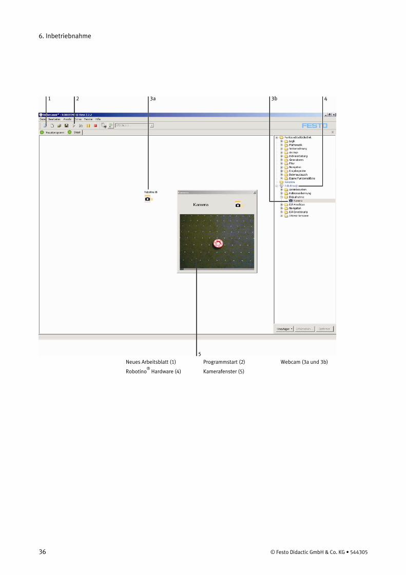
• Öffnen Sie eine neue Arbeitsfläche indem Sie auf das Symbol (1) hierfür in der Werkzeugleiste klicken.
• Öffnen Sie nun den Ordner "Robotino®
• Ziehen Sie dann das Kamerasymbol (3b) mit gedrückter Maustaste auf die Arbeitsfläche.
Hardware" (4) indem Sie ihn anklicken.
• Klicken Sie auf den grünen Pfeil in der Werkzeugleiste (2), um das Programm zu starten
• Öffnen Sie ein Fenster (5) mit dem aktuellen Kamerabild indem Sie auf das Kamerasymbol auf der Arbeitsfläche (3a) doppelklicken. Wenn Sie die Arbeitsfläche verkleinern, können Sie das Fenster mit dem Kamerabild vergrößern.
6. Inbetriebnahme
36 © Festo Didactic GmbH & Co. KG • 544305
Neues Arbeitsblatt (1) Programmstart (2) Webcam (3a und 3b)
Robotino®
Hardware (4) Kamerafenster (5)
6. Inbetriebnahme
© Festo Didactic GmbH & Co. KG • 544305 37
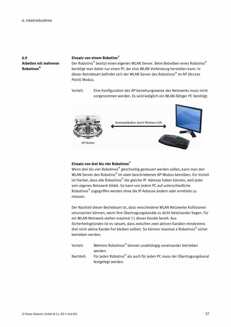
Einsatz von einem RobotinoDer Robotino
® ® besitzt einen eigenen WLAN Server. Beim Betreiben eines Robotino®
benötigt man daher nur einen PC der eine WLAN Verbindung herstellen kann. In dieser Betriebsart befindet sich der WLAN Server des Robotinos®
im AP (Access Point) Modus.
Vorteil: Eine Konfiguration des AP beziehungsweise des Netzwerks muss nicht vorgenommen werden. Es wird lediglich ein WLAN-fähiger PC benötigt.
Einsatz von drei bis vier Robotinos®
Wenn drei bis vier Robotinos
® gleichzeitig gesteuert werden sollen, kann man den WLAN-Server des Robotino® im oben beschriebenen AP-Modus betreiben. Ein Vorteil ist hierbei, dass alle Robotinos® die gleiche IP- Adresse haben können, weil jeder sein eigenes Netzwerk bildet. So kann von Jedem PC auf unterschiedliche Robotinos®
zugegriffen werden ohne die IP-Adresse ändern oder ermitteln zu müssen.
Der Nachteil dieser Betriebsart ist, dass verschiedene WLAN Netzwerke Kollisionen verursachen können, wenn ihre Übertragungskanäle zu dicht beieinander liegen. Für ein WLAN-Netzwerk stehen maximal 11 dieser Kanäle bereit. Aus Sicherheitsgründen ist es ratsam, dass zwischen zwei aktiven Kanälen mindestens drei nicht aktive Kanäle frei bleiben sollten. So können maximal 4 Robotinos®
sicher betrieben werden.
Vorteil: Mehrere Robotinos®
Nachteil: Für jeden Robotino
können unabhängig voneinander betrieben werden.
®
als auch für jeden PC muss der Übertragungskanal festgelegt werden.
6.9 Arbeiten mit mehreren Robotinos®
6. Inbetriebnahme
38 © Festo Didactic GmbH & Co. KG • 544305
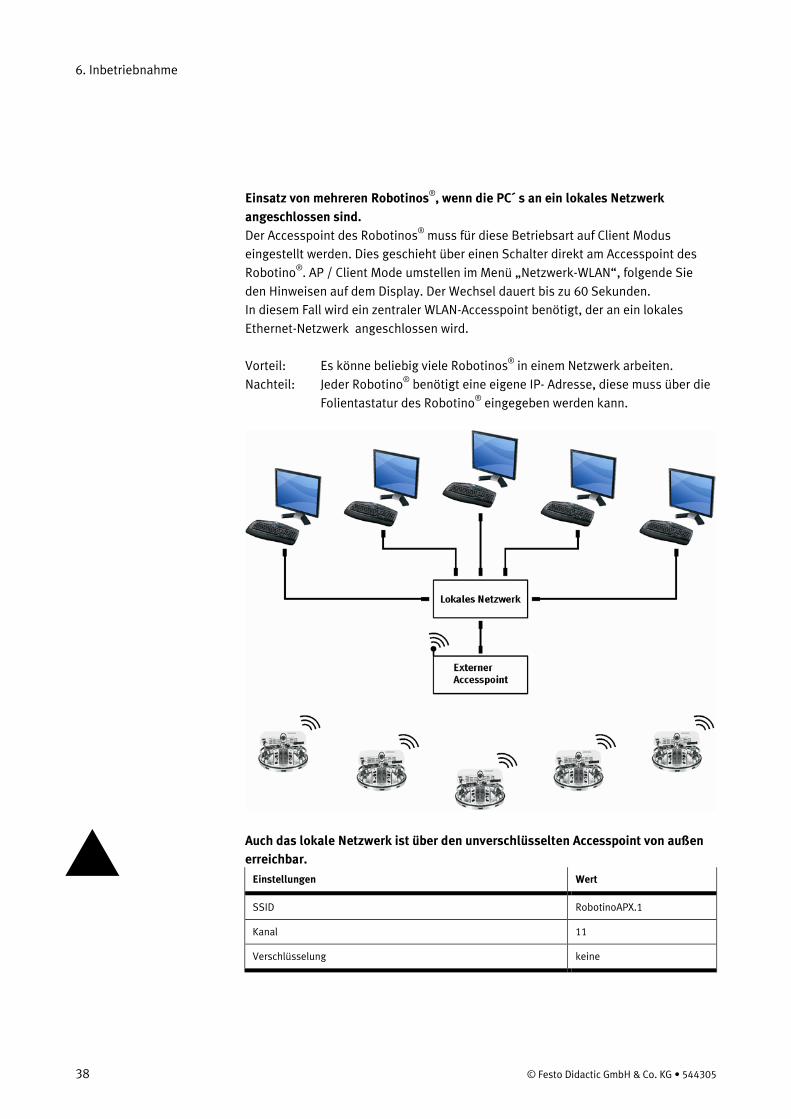
Einsatz von mehreren Robotinos®
Der Accesspoint des Robotinos
, wenn die PC´ s an ein lokales Netzwerk angeschlossen sind.
® muss für diese Betriebsart auf Client Modus eingestellt werden. Dies geschieht über einen Schalter direkt am Accesspoint des Robotino®
. AP / Client Mode umstellen im Menü „Netzwerk-WLAN“, folgende Sie den Hinweisen auf dem Display. Der Wechsel dauert bis zu 60 Sekunden. In diesem Fall wird ein zentraler WLAN-Accesspoint benötigt, der an ein lokales Ethernet-Netzwerk angeschlossen wird.
Vorteil: Es könne beliebig viele Robotinos®
Nachteil: Jeder Robotino in einem Netzwerk arbeiten.
® benötigt eine eigene IP- Adresse, diese muss über die Folientastatur des Robotino®
eingegeben werden kann.
Auch das lokale Netzwerk ist über den unverschlüsselten Accesspoint von außen erreichbar.
Einstellungen Wert
SSID RobotinoAPX.1
Kanal 11
Verschlüsselung keine
6. Inbetriebnahme
© Festo Didactic GmbH & Co. KG • 544305 39
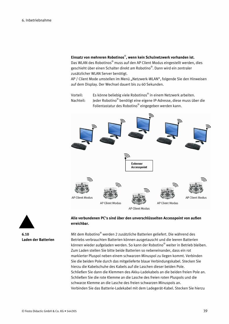
Einsatz von mehreren Robotinos®
Das WLAN des Robotinos, wenn kein Schulnetzwerk vorhanden ist.
® muss auf den AP Client Modus eingestellt werden, dies geschieht über einen Schalter direkt am Robotino®
AP / Client Mode umstellen im Menü „Netzwerk-WLAN“, folgende Sie den Hinweisen auf dem Display. Der Wechsel dauert bis zu 60 Sekunden.
. Dann wird ein zentraler zusätzlicher WLAN Server benötigt.
Vorteil: Es könne beliebig viele Robotinos®
Nachteil: Jeder Robotino in einem Netzwerk arbeiten.
® benötigt eine eigene IP-Adresse, diese muss über die Folientastatur des Robotino®
eingegeben werden kann.
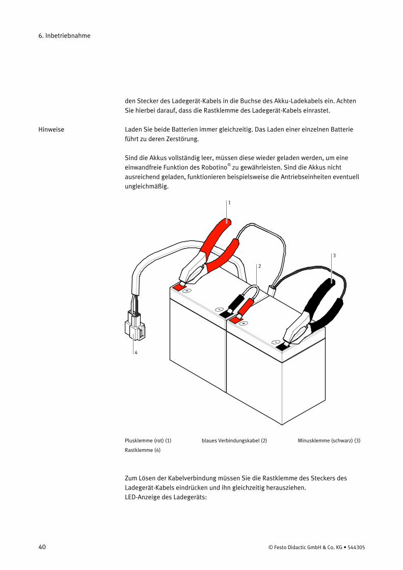
Alle verbundenen PC's sind über den unverschlüsselten Accesspoint von außen erreichbar. Mit dem Robotino® werden 2 zusätzliche Batterien geliefert. Die während des Betriebs verbrauchten Batterien können ausgetauscht und die leeren Batterien können wieder aufgeladen werden. So kann der Robotino® weiter in Betrieb bleiben. Zum Laden stellen Sie bitte beide Batterien so nebeneinander, dass ein rot markierter Pluspol neben einem schwarzen Minuspol zu liegen kommt. Verbinden Sie die beiden Pole durch das mitgelieferte blaue Verbindungskabel. Stecken Sie hierzu die Kabelschuhe des Kabels auf die Laschen dieser beiden Pole. Schließen Sie dann die Klemmen des Akku-Ladekabels an die beiden freien Pole an. Schließen Sie die rote Klemme an die Lasche des freien roten Pluspols und die schwarze Klemme an die Lasche des freien schwarzen Minuspols an. Verbinden Sie das Batterie-Ladekabel mit dem Ladegerät-Kabel. Stecken Sie hierzu
6.10 Laden der Batterien
6. Inbetriebnahme
40 © Festo Didactic GmbH & Co. KG • 544305
den Stecker des Ladegerät-Kabels in die Buchse des Akku-Ladekabels ein. Achten Sie hierbei darauf, dass die Rastklemme des Ladegerät-Kabels einrastet. Laden Sie beide Batterien immer gleichzeitig. Das Laden einer einzelnen Batterie führt zu deren Zerstörung. Sind die Akkus vollständig leer, müssen diese wieder geladen werden, um eine einwandfreie Funktion des Robotino®
zu gewährleisten. Sind die Akkus nicht ausreichend geladen, funktionieren beispielsweise die Antriebseinheiten eventuell ungleichmäßig.
4
1
3
2
Plusklemme (rot) (1) blaues Verbindungskabel (2) Minusklemme (schwarz) (3)
Rastklemme (4)
Zum Lösen der Kabelverbindung müssen Sie die Rastklemme des Steckers des Ladegerät-Kabels eindrücken und ihn gleichzeitig herausziehen. LED-Anzeige des Ladegeräts:
Hinweise
6. Inbetriebnahme
© Festo Didactic GmbH & Co. KG • 544305 41
Farbe der LED Zustand
Rot Betrieb
Orange Laden
Grün Ladeende
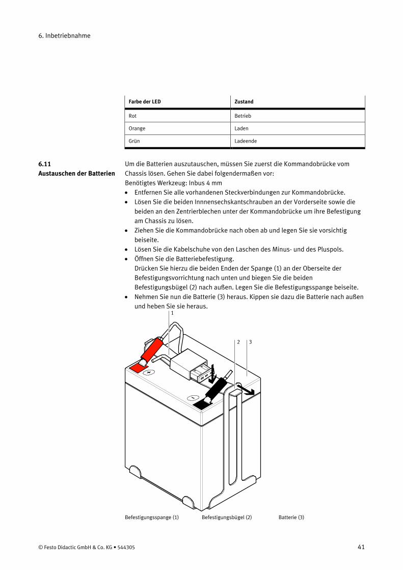
Um die Batterien auszutauschen, müssen Sie zuerst die Kommandobrücke vom Chassis lösen. Gehen Sie dabei folgendermaßen vor: Benötigtes Werkzeug: Inbus 4 mm • Entfernen Sie alle vorhandenen Steckverbindungen zur Kommandobrücke. • Lösen Sie die beiden Innnensechskantschrauben an der Vorderseite sowie die
beiden an den Zentrierblechen unter der Kommandobrücke um ihre Befestigung am Chassis zu lösen.
• Ziehen Sie die Kommandobrücke nach oben ab und legen Sie sie vorsichtig beiseite.
• Lösen Sie die Kabelschuhe von den Laschen des Minus- und des Pluspols. • Öffnen Sie die Batteriebefestigung.
Drücken Sie hierzu die beiden Enden der Spange (1) an der Oberseite der Befestigungsvorrichtung nach unten und biegen Sie die beiden Befestigungsbügel (2) nach außen. Legen Sie die Befestigungsspange beiseite.
• Nehmen Sie nun die Batterie (3) heraus. Kippen sie dazu die Batterie nach außen und heben Sie sie heraus.
1
2 3
Befestigungsspange (1) Befestigungsbügel (2) Batterie (3)
6.11 Austauschen der Batterien
6. Inbetriebnahme
42 © Festo Didactic GmbH & Co. KG • 544305
Wiederholen Sie den obigen Vorgang für die zweite Batterie. Gehen Sie beim Montieren der Austausch-Batterien umgekehrt vor. Beachten Sie dabei folgendes: • Achten Sie darauf, dass keine Kabel durch die Batterie eingeklemmt werden. • Beide Pole der Batterien müssen zum Zentrum des Robotino®
Die Kabel müssen folgendermaßen an die Pole der Batterie angeschlossen werden:
zeigen.
• Das Kabel mit dem schwarzen Kabelschuh muss an den Minuspol (schwarz, links) angeschlossen werden.
• Das Kabel mit dem roten Kabelschuh muss an den Pluspol (rot, rechts) angeschlossen werden.
6. Inbetriebnahme
© Festo Didactic GmbH & Co. KG • 544305 43
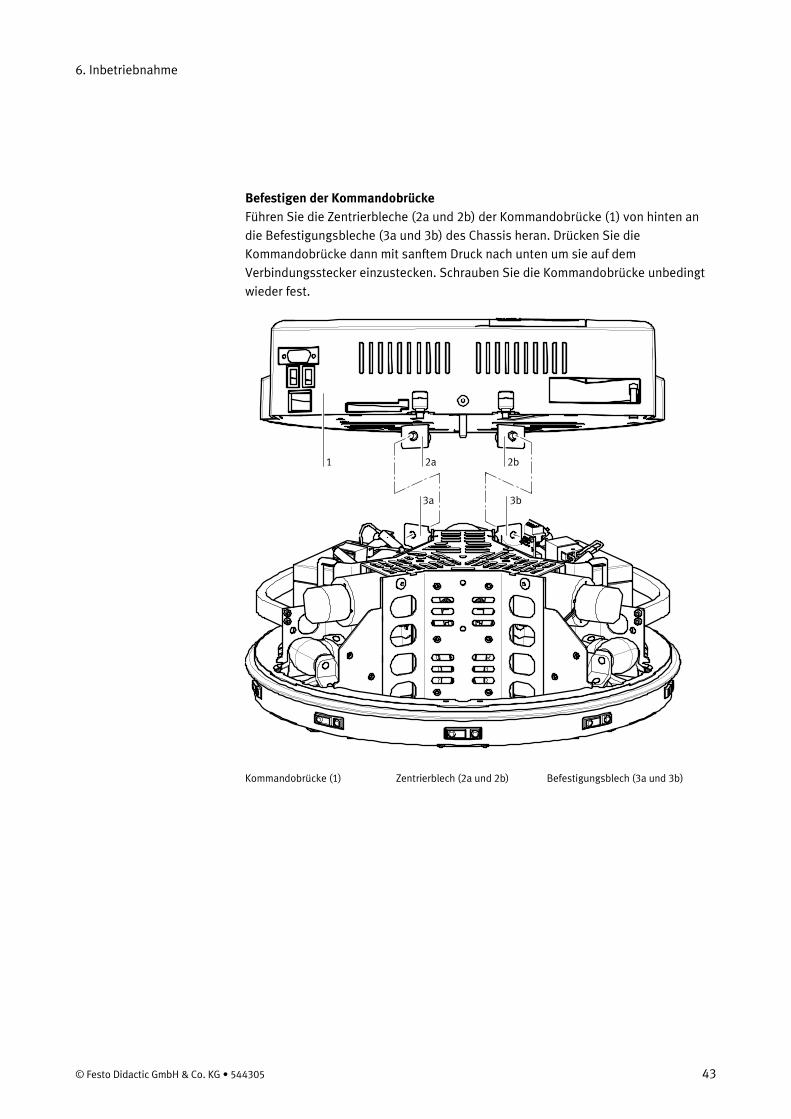
Befestigen der Kommandobrücke Führen Sie die Zentrierbleche (2a und 2b) der Kommandobrücke (1) von hinten an die Befestigungsbleche (3a und 3b) des Chassis heran. Drücken Sie die Kommandobrücke dann mit sanftem Druck nach unten um sie auf dem Verbindungsstecker einzustecken. Schrauben Sie die Kommandobrücke unbedingt wieder fest.
1 2a 2b
3a 3b
Kommandobrücke (1) Zentrierblech (2a und 2b) Befestigungsblech (3a und 3b)
6. Inbetriebnahme
44 © Festo Didactic GmbH & Co. KG • 544305
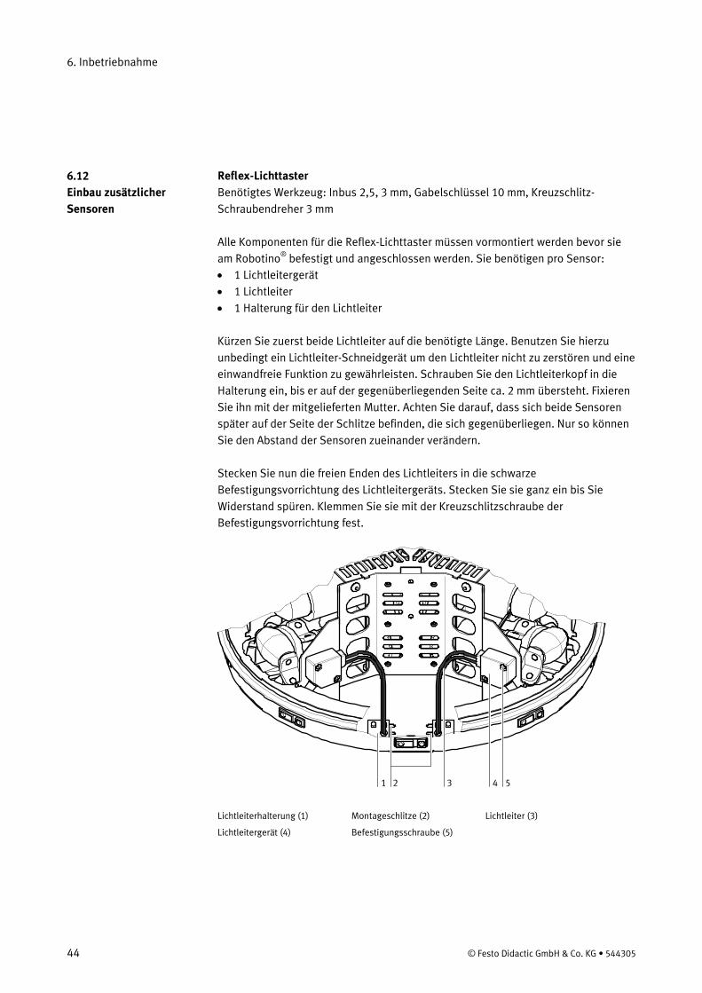
Reflex-Lichttaster Benötigtes Werkzeug: Inbus 2,5, 3 mm, Gabelschlüssel 10 mm, Kreuzschlitz-Schraubendreher 3 mm Alle Komponenten für die Reflex-Lichttaster müssen vormontiert werden bevor sie am Robotino®
• 1 Lichtleitergerät befestigt und angeschlossen werden. Sie benötigen pro Sensor:
• 1 Lichtleiter • 1 Halterung für den Lichtleiter Kürzen Sie zuerst beide Lichtleiter auf die benötigte Länge. Benutzen Sie hierzu unbedingt ein Lichtleiter-Schneidgerät um den Lichtleiter nicht zu zerstören und eine einwandfreie Funktion zu gewährleisten. Schrauben Sie den Lichtleiterkopf in die Halterung ein, bis er auf der gegenüberliegenden Seite ca. 2 mm übersteht. Fixieren Sie ihn mit der mitgelieferten Mutter. Achten Sie darauf, dass sich beide Sensoren später auf der Seite der Schlitze befinden, die sich gegenüberliegen. Nur so können Sie den Abstand der Sensoren zueinander verändern. Stecken Sie nun die freien Enden des Lichtleiters in die schwarze Befestigungsvorrichtung des Lichtleitergeräts. Stecken Sie sie ganz ein bis Sie Widerstand spüren. Klemmen Sie sie mit der Kreuzschlitzschraube der Befestigungsvorrichtung fest.
1 2 3 4 5 Lichtleiterhalterung (1) Montageschlitze (2) Lichtleiter (3)
Lichtleitergerät (4) Befestigungsschraube (5)
6.12 Einbau zusätzlicher Sensoren
6. Inbetriebnahme
© Festo Didactic GmbH & Co. KG • 544305 45
Montieren Sie nun die Sensoren am Chassis des Robotino®
. Befestigen Sie die Lichtleiterhalterung (1) am Boden des Chassis indem Sie diese durch einen Schlitz von unten mit 2 Schrauben befestigen. Die Schlitze (2) vorne im Boden des Chassis für die Halterung haben unterschiedliche Funktionen. Der lange Schlitz dient zur Befestigung der Halterung. Der kurze Schlitz dient dazu, den Lichtstrahl des Lichtleiters passieren zu lassen. Ob Sie die Lichtleiter (3) mehr oder weniger weit auseinander montieren müssen, hängt von der Breite des zu erkennenden Objekts ab.
Schrauben Sie die Lichtleiterhalterung an die dafür vorgesehene Stelle des Chassis. Die Halterung wird mit den beigefügten Schrauben (Innensechskant 3 mm) von unten angeschraubt. Montieren Sie beide Halterungen. Achten Sie darauf, dass sich der Lichtleiterkopf im zugehörigen Schlitz befindet! Montieren Sie nun das Lichtleitergerät (4) am Montageblech des Robotino®
. Schrauben Sie es mit den mitgelieferten Schrauben (5) an den beiden dafür vorgesehenen Gewindebohrungen fest.
Induktiver Analogsensor Der analoge induktive Sensor wird in der fest eingebauten Befestigungsvorrichtung lediglich eingespannt. Lösen Sie hierzu die Rändelschraube an der Befestigungsvorrichtung: Schieben Sie den Sensor mit der Steckerseite nach oben in die vorgesehene Bohrung, halten Sie sie in der gewünschten Position und drehen Sie die Rändelschraube wieder zu. Dem Sensor liegt ein Kabel mit Stecker bei. Stecken Sie das Kabel auf den Sensor auf und drehen Sie die Rändelmutter fest. Beachten Sie den Erfassungsbereich des Sensors! Alle Sensoren werden über die Steckerleiste mit der E/A-Schittstelle und somit mit der Steuerung verbunden. Belegung der E/A-Schnittstelle und Beschaltung der Sensoren entnehmen Sie bitte dieser Dokumentation beziehungsweise den Datenblättern der einzelnen Sensoren.
Hinweis
Hinweis
6.13 Anschluss der Sensoren
6. Inbetriebnahme
46 © Festo Didactic GmbH & Co. KG • 544305
Robotino hat viele Schnittstellen zu Hochsprachen. Die DEMO-Programme im Menü sind z.B. in C++ geschrieben. Der Quellcode dieser und vieler weiterer Beispielprogramme befindet sich auf der Speicherkarte von Robotino und kann dort direkt verändert und kompiliert werden. Für die individuelle Modifikation oder Erweiterung der Funktionen des Robotino®
stehen Ihnen unterschiedliche Möglichkeiten der Programmierung durch C++ zur Verfügung.
Auf der mitgelieferten CD-ROM befinden sich C++-Bibliotheken zur Programmierung mit MS Visual Studio 2005 oder höher. Diese Funktionen ermöglichen es, eigene Programme erstellen, die die Kommunikation mit dem Robotino® und die Steuerung des Robotino®
vom PC regeln.
Die Beschreibung der Funktionen und Bibliotheken entnehmen Sie bitte den programminternen Kommentaren. Auf dem PC 104 des Robotino® befinden sich die gleichen Bibliotheken, Funktionen und Quelldaten für die Robotino®
-Beispielprogramme in einer Linux-Version. Sie können mit dem Linux-eigenen Editor bearbeitet werden.
Grundsätzlich bestehen zwei Möglichkeiten, auf die Funktionen, Bibliotheken und Beispielprogramme auf dem PC 104 zuzugreifen. • Die eine Möglichkeit besteht darin, mit einem Terminalprogramm über eine
WLAN-Verbindung auf die Linux-Umgebung des PC 104 zuzugreifen. • Die zweite Möglichkeit besteht darin, Tastatur und Bildschirm direkt an den PC
104 anzuschließen und so auf das Linux-Betriebssystem zuzugreifen. Zugriff mit Hilfe eines Terminalprogramms Auf der mitgelieferten CD-ROM befindet sich das Terminalprogramm Putty (putty_0_58.exe). Es befindet 1. Stellen Sie eine WLAN-Verbindung zum Robotino®
2. Starten Sie das Programm putty_0_58.exe. Geben Sie in die Adresszeile (host name (or IP-adress) die IP-Adresse des Robotino
her.
® ein und klicken Sie auf die Schaltfläche "Open". Die Verbindung mit dem PC 104 des Robotino®
3. Geben Sie an der Eingabeaufforderung als Login-Namen "robotino" ein. Bestätigen Sie mit der Eingabetaste. Anschließend werden Sie aufgefordert, das Passwort einzugeben. Geben Sie erneut "robotino" ein und bestätigen Sie Ihre Eingabe erneut.
wird hergestellt.
6.14 C++-Bibliotheken
6. Inbetriebnahme
© Festo Didactic GmbH & Co. KG • 544305 47
Zugriff über die Systemschnittstellen des PC 104 1. Schließen Sie ihre Tastatur über einen des beiden USB-Ports und einen Monitor
an die VGA-Schnittstelle des PC 104 an. Die Verbindung ist hiermit hergestellt. 2. Geben Sie an der Eingabeaufforderung als Login-Namen "robotino" ein.
Bestätigen Sie mit der Eingabetaste. Anschließend werden Sie aufgefordert, das Passwort einzugeben. Geben Sie erneut "robotino" ein und bestätigen Sie Ihre Eingabe erneut.
In beiden Fällen befinden Sie sich dann im home-Verzeichnis des Benutzers "robotino" der Linux-Umgebung des PC 104. Von hier aus können Sie auf alle Programme, Quellcodes und Bibliotheken zugreifen. Im Verzeichnis "examples" die Beispielprogramme des Robotino®
mit ihrem Quelldaten und einer kompilierten Version.
Das Programm Kreis (Circle). Wechseln Sie in das Verzeichnis /robotino/examples/circle und führen Sie das Programm aus, indem Sie "./circle" an der Eingabeaufforderung eingeben. Der Befehl startet das schon kompilierte Kreisfahrtbeispiel (übrigens das selbe, welches Sie über das Display starten können). Mit einem Editor (z.B. nano) können Sie jetzt den Quellcode editieren und mit make neu übersetzen.
Beispiel
48 © Festo Didactic GmbH & Co. KG • 544305
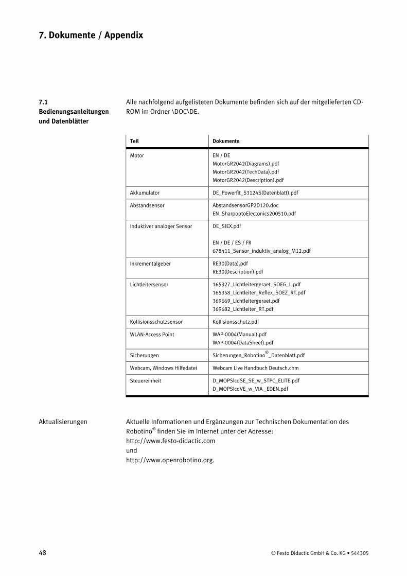
Alle nachfolgend aufgelisteten Dokumente befinden sich auf der mitgelieferten CD-ROM im Ordner \DOC\DE.
Teil Dokumente
Motor EN / DE
MotorGR2042(Diagrams).pdf
MotorGR2042(TechData).pdf
MotorGR2042(Description).pdf
Akkumulator DE_Powerfit_S3124S(Datenblatt).pdf
Abstandsensor AbstandsensorGP2D120.doc
EN_SharpoptoElectonics200510.pdf
Induktiver analoger Sensor DE_SIEX.pdf
EN / DE / ES / FR
678411_Sensor_induktiv_analog_M12.pdf
Inkrementalgeber RE30(Data).pdf
RE30(Description).pdf
Lichtleitersensor 165327_Lichtleitergeraet_SOEG_L.pdf
165358_Lichtleiter_Reflex_SOEZ_RT.pdf
369669_Lichtleitergeraet.pdf
369682_Lichtleiter_RT.pdf
Kollisionsschutzsensor Kollisionsschutz.pdf
WLAN-Access Point WAP-0004(Manual).pdf
WAP-0004(DataSheet).pdf
Sicherungen Sicherungen_Robotino®
Webcam, Windows Hilfedatei
_Datenblatt.pdf
Webcam Live Handbuch Deutsch.chm
Steuereinheit D_MOPSlcdSE_SE_w_STPC_ELITE.pdf
D_MOPSlcdVE_w_VIA _EDEN.pdf
Aktuelle Informationen und Ergänzungen zur Technischen Dokumentation des Robotino®
http://www.festo-didactic.com finden Sie im Internet unter der Adresse:
und http://www.openrobotino.org.
7. Dokumente / Appendix
7.1 Bedienungsanleitungen und Datenblätter
Aktualisierungen
© Festo Didactic GmbH & Co. KG • 544305 49
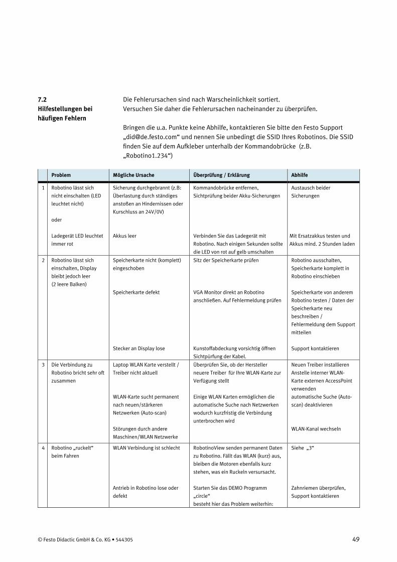
Die Fehlerursachen sind nach Warscheinlichkeit sortiert. Versuchen Sie daher die Fehlerursachen nacheinander zu überprüfen. Bringen die u.a. Punkte keine Abhilfe, kontaktieren Sie bitte den Festo Support „[email protected]“ und nennen Sie unbedingt die SSID Ihres Robotinos. Die SSID finden Sie auf dem Aufkleber unterhalb der Kommandobrücke (z.B. „Robotino1.234“)
Problem Mögliche Ursache Überprüfung / Erklärung Abhilfe
1 Robotino lässt sich
nicht einschalten (LED
leuchtet nicht)
oder
Ladegerät LED leuchtet
immer rot
Sicherung durchgebrannt (z.B:
Überlastung durch ständiges
anstoßen an Hindernissen oder
Kurschluss an 24V/0V)
Akkus leer
Kommandobrücke entfernen,
Sichtprüfung beider Akku-Sicherungen
Verbinden Sie das Ladegerät mit
Robotino. Nach einigen Sekunden sollte
die LED von rot auf gelb umschalten
Austausch beider
Sicherungen
Mit Ersatzakkus testen und
Akkus mind. 2 Stunden laden
2 Robotino lässt sich
einschalten, Display
bleibt jedoch leer
(2 leere Balken)
Speicherkarte nicht (komplett)
eingeschoben
Speicherkarte defekt
Stecker an Display lose
Sitz der Speicherkarte prüfen
VGA Monitor direkt an Robotino
anschließen. Auf Fehlermeldung prüfen
Kunstoffabdeckung vorsichtig öffnen
Sichtpürfung der Kabel.
Robotino ausschalten,
Speicherkarte komplett in
Robotino einschieben
Speicherkarte von anderem
Robotino testen / Daten der
Speicherkarte neu
beschreiben /
Fehlermeldung dem Support
mitteilen
Support kontaktieren
3 Die Verbindung zu
Robotino bricht sehr oft
zusammen
Laptop WLAN Karte verstellt /
Treiber nicht aktuell
WLAN-Karte sucht permanent
nach neuen/stärkeren
Netzwerken (Auto-scan)
Störungen durch andere
Maschinen/WLAN Netzwerke
Überprüfen Sie, ob der Hersteller
neuere Treiber für Ihre WLAN-Karte zur
Verfügung stellt
Einige WLAN Karten ermöglichen die
automatische Suche nach Netzwerken
wodurch kurzfristig die Verbindung
unterbrochen wird
Neuen Treiber installieren
Anstelle interner WLAN-
Karte externen AccessPoint
verwenden
automatische Suche (Auto-
scan) deaktivieren
WLAN-Kanal wechseln
4 Robotino „ruckelt“
beim Fahren
WLAN Verbindung ist schlecht
Antrieb in Robotino lose oder
defekt
RobotinoView senden permanent Daten
zu Robotino. Fällt das WLAN (kurz) aus,
bleiben die Motoren ebenfalls kurz
stehen, was ein Ruckeln versursacht.
Starten Sie das DEMO Programm
„circle“
besteht hier das Problem weiterhin:
Siehe „3“
Zahnriemen überprüfen,
Support kontaktieren
7.2 Hilfestellungen bei häufigen Fehlern
50 © Festo Didactic GmbH & Co. KG • 544305
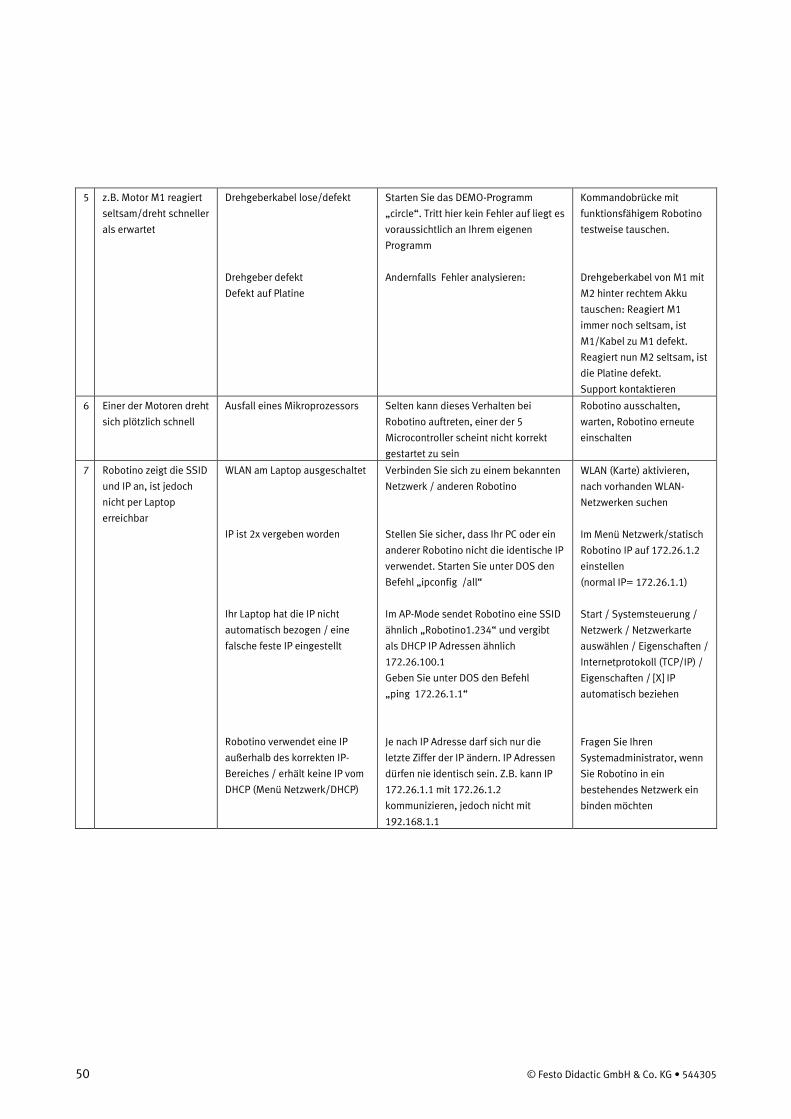
5 z.B. Motor M1 reagiert
seltsam/dreht schneller
als erwartet
Drehgeberkabel lose/defekt
Drehgeber defekt
Defekt auf Platine
Starten Sie das DEMO-Programm
„circle“. Tritt hier kein Fehler auf liegt es
voraussichtlich an Ihrem eigenen
Programm
Andernfalls Fehler analysieren:
Kommandobrücke mit
funktionsfähigem Robotino
testweise tauschen.
Drehgeberkabel von M1 mit
M2 hinter rechtem Akku
tauschen: Reagiert M1
immer noch seltsam, ist
M1/Kabel zu M1 defekt.
Reagiert nun M2 seltsam, ist
die Platine defekt.
Support kontaktieren
6 Einer der Motoren dreht
sich plötzlich schnell
Ausfall eines Mikroprozessors Selten kann dieses Verhalten bei
Robotino auftreten, einer der 5
Microcontroller scheint nicht korrekt
gestartet zu sein
Robotino ausschalten,
warten, Robotino erneute
einschalten
7 Robotino zeigt die SSID
und IP an, ist jedoch
nicht per Laptop
erreichbar
WLAN am Laptop ausgeschaltet
IP ist 2x vergeben worden
Ihr Laptop hat die IP nicht
automatisch bezogen / eine
falsche feste IP eingestellt
Robotino verwendet eine IP
außerhalb des korrekten IP-
Bereiches / erhält keine IP vom
DHCP (Menü Netzwerk/DHCP)
Verbinden Sie sich zu einem bekannten
Netzwerk / anderen Robotino
Stellen Sie sicher, dass Ihr PC oder ein
anderer Robotino nicht die identische IP
verwendet. Starten Sie unter DOS den
Befehl „ipconfig /all“
Im AP-Mode sendet Robotino eine SSID
ähnlich „Robotino1.234“ und vergibt
als DHCP IP Adressen ähnlich
172.26.100.1
Geben Sie unter DOS den Befehl
„ping 172.26.1.1“
Je nach IP Adresse darf sich nur die
letzte Ziffer der IP ändern. IP Adressen
dürfen nie identisch sein. Z.B. kann IP
172.26.1.1 mit 172.26.1.2
kommunizieren, jedoch nicht mit
192.168.1.1
WLAN (Karte) aktivieren,
nach vorhanden WLAN-
Netzwerken suchen
Im Menü Netzwerk/statisch
Robotino IP auf 172.26.1.2
einstellen
(normal IP= 172.26.1.1)
Start / Systemsteuerung /
Netzwerk / Netzwerkarte
auswählen / Eigenschaften /
Internetprotokoll (TCP/IP) /
Eigenschaften / [X] IP
automatisch beziehen
Fragen Sie Ihren
Systemadministrator, wenn
Sie Robotino in ein
bestehendes Netzwerk ein
binden möchten
© Festo Didactic GmbH & Co. KG • 544305 51
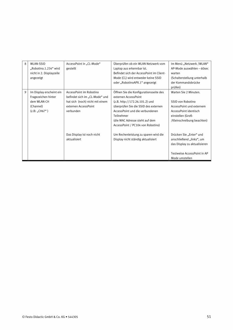
8 WLAN-SSID
„Robotino.1.234“ wird
nicht in 2. Displayzeile
angezeigt
AccessPoint in „CL-Mode“
gestellt
Überprüfen ob ein WLAN Netzwerk vom
Laptop aus erkennbar ist.
Befindet sich der AccessPoint im Client-
Mode (CL) wird entweder keine SSID
oder „RobotinoAPX.1“ angezeigt
Im Menü „Netzwerk /WLAN“
AP-Mode auswählen – 60sec
warten
(Schalterstellung unterhalb
der Kommandobrücke
prüfen)
9 Im Display erscheint ein
Fragezeichen hinter
dem WLAN-CH
(Channel)
(z.B: „CH6?“ )
AccessPoint im Robotino
befindet sich im „CL-Mode“ und
hat sich (noch) nicht mit einem
externen AccessPoint
verbunden
Das Display ist noch nicht
aktualisiert
Öffnen Sie die Konfigurationsseite des
externen AccessPoint
(z.B. http://172.26.101.2) und
überprüfen Sie die SSID des externen
AccessPoint und die verbundenen
Teilnehmer
(die MAC Adresse steht auf dem
AccessPoint / PC104 von Robotino)
Um Rechenleistung zu sparen wird die
Display nicht ständig aktualisiert
Warten Sie 2 Minuten.
SSID von Robotino
AccessPoint und externem
AccessPoint identisch
einstellen (Groß-
/Kleinschreibung beachten)
Drücken Sie „Enter“ und
anschließend „links“, um
das Display zu aktualisieren
Testweise AccessPoint in AP
Mode umstellen
52 © Festo Didactic GmbH & Co. KG • 544305
Aktuelle Speicherkarte: Die Speicherkarte ist vollständig getestet und beinhaltet stets die neuste Version des Betriebssystems. Alternativ können Sie Updates kostenlos von unserer Homepage auf Ihre bestehende Speicherkarte laden. Greifersystem Robotino wird zum FahrerlosenTransportSystem (FTS) - (engl: automated guidedvehicle [abbr.: AGV] ) Transportieren Sie z.B. Werkstücke von einer zu einer anderen MPS-Station Northstar-Sensor mit Boardmitteln kann ein mobiler Roboter nur relative Bewegungen detektieren – mit diesem Sensor erhält Robotino eine absolute Position im Raum Gyroskope Sensor ist notwendig um präzise Drehbewegungen auszuführen, dies ist besonders bei größeren Stecken enorm wichtig Netzwerkkarten Option (network-switch) für Ein-/Ausgangskarte „EA09“ : Direkte Erreichbarkeit von IO-Platine/PC104/AccessPoint und Laptop u.a. zum hochfrequenten Analyse der PID-Controller / Hardware in the Loop / direkte Programmierung des Microporzessors Externer AccessPoint: Durch die Verwendung eines externen AccessPoints können viele WLAN-Unterbrechungsprobleme von z.B. internen Laptop WLAN-Karten behoben werden. Ebenfalls kann ein bestehendes (Schul-)Netzwerk mit mehreren Robotinos verbunden werden. Bitte den Systemadministrator einbeziehen, und die WLAN-Verschlüsselung aktivieren Zusätzliche Informationen und Erweiterungen finden siehe unter http://www.festo-didactic.com Projektideen anderer Kunden finden Sie unter http://www.openrobotino.org
Optionale Hardwarekomponenten:
© Festo Didactic GmbH & Co. KG • 544305 53
The Festo Didactic Learning System for Automation and Technology is designed to meet a number of different training and vocational requirements. The mobile robot system Robotino®
facilitates industry-orientated vocational and further training and the hardware consists of didactically suitable industrial components.
The mobile robot system Robotino®
• Social competence,
provides you with an appropriate system for practice-orientated tuition of the following key qualifications
• Technical competence and • Methodological competence Training contents covering the following subjects can be taught: • Mechanics
– Mechanical construction of a mobile robot system • Electrical
– Control of drive units – Correct wiring of electrical components
• Sensors – Sensor-guided path control – Collision-free path control with distance sensors – Path control by image processing of webcam pictures
• Feedback control systems – Control of omnidirectional drives
• Use of communication interfaces – Wireless LAN
• Commissioning – Commissioning of a mobile robot system
Beside industrial robot technology grows the market and therefore the importance of mobile robot systems and service robots. With Robotino®
education responds to this technical and economic trend.
With Robotino®
the learning aims below can be achieved.
1.1 Training contents
1. Introduction
1.2 Learning aims
1. Introduction
54 © Festo Didactic GmbH & Co. KG • 544305
The trainees – learn to manage an electrically controlled drive unit – know the fundamentals, the construction, the measurement of values and the
parameterisation of a direct current motor control – know the fundamentals of electrical drive technology – understand an omnidirectional 3-axis drive and know to operate it – are able to realise the commissioning of a mobile robot system using the
Robotino®
– can move the Robotino as an example
®
– can realise a sensor-guided path control in different directions
– can integrate image processing into the control of the Robotino®
– can develop a sensor- guided autonomous path control of the Robotino
®
Furthermore the following additional training aims can be achieved
using object recognition for example by colour.
– mounting and integration of additional sensors into the mobile robot system Robotino®
– can mount and integrate handling devices into the system
– are able to program their own navigation and control algorithms using a C++ library
– create a autonomous navigation of the Robotino®
.
The basic requirement for safe use and trouble-free operation of the mobile robot system Robotino®
is to observe the fundamental safety recommendations and regulations.
This manual contains important notes concerning the safe operation of the mobile robot system Robotino®
.
The safety recommendations in particular must be observed by anyone working on the mobile robot system Robotino®
.
Furthermore, the rules and regulations for the prevention of accidents applicable to the place of use must be observed.
1.3 Important notes
1. Introduction
© Festo Didactic GmbH & Co. KG • 544305 55
The operating authority undertakes to ensure that the Robotino®
• are familiar with the basic regulations regarding operational safety and accident prevention and who have received instructions in the handling of the Robotino
is used only by persons who:
®
• have read and understood the chapter on safety and the cautionary notes in this manual.
,
Safety-conscious working of the persons should be regularly vetted. Prior to commencing work, all persons assigned to working on the mobile robot system Robotino®
• read the chapter on safety and the cautionary notes in this manual and, have a duty to:
• observe the basic regulations regarding operational safety and the prevention of accidents.
The Robotino®
is designed according to state of the art technology and in compliance with recognised safety regulations. However when using the system there is nevertheless a risk of physical or fatal injury to the user or third parties or of damage being caused to the machinery or other material assets.
The Robotino®
• for its intended purpose and is to be used only:
• in an absolutely safe condition. Faults impairing safety must be rectified immediately!
1.4 Duty of the operating authority
1.5 Duty of trainees
1.6 Risks involved in dealing with the mobile robot system
1. Introduction
56 © Festo Didactic GmbH & Co. KG • 544305
In principle all our „Terms and Conditions of Sale“ apply. These are available to the operating authority upon conclusion of the contract at the latest. Warranty and liability claims for persons or material damage are excluded if these can be traced back to one or several of the following causes: • Use of the Robotino®
• Incorrect assembly, commissioning, operation and maintenance of the Robotino not in accordance with its intended purpose
• Operation of the Robotino
® ®
• Non observance of notes in the manual regarding transport, storage, assembly, commissioning, operation, maintenance and setting up of the Robotino
using faulty safety equipment or incorrectly fitted or non operational safety or protective devices
• Unlawful constructional modifications on the Robotino
®
• Inadequate monitoring of components subject to wear
®
• Incorrectly carried out repairs • Catastrophies as a result of foreign bodies and vis major.
Festo Didactic herewith rules out any liability for damage or injury to trainees, the training company and/or other third parties which may occur during the use/operation of the system other than purely in a training situation, unless such damage has been caused intentionally or due to gross negligence by Festo Didactic. This system has been developed and produced exclusively for vocational and further training in the field of automation and technology. The training authority and/or the instructors is/are to ensure that trainees observe the safety precautions described in the manual provided. The use of the system for its intended purpose also includes: • following all advice in the manual and • carrying out inspection and maintenance work.
1.7 Warranty and liability
1.8 Intended use
© Festo Didactic GmbH & Co. KG • 544305 57
General • Trainees must only work on the Robotino®
• Observe the data in the data sheets for the individual components, in particular all notes on safety!
under the supervision of an instructor.
Electrics • Electrical connections are to be wired up or disconnected only when power is
disconnected! • Use only low voltages of up to 24 V DC. Mechanics • Move the Robotino®
• Securely mount all components on the chassis. only by carefully seizing it by its handles.
• No manual intervention unless the Robotino®
is at rest.
2. Notes on safety
58 © Festo Didactic GmbH & Co. KG • 544305
Parameter Value
Voltage supply 24 V DC, 4.5 A
Digital inputs 8
Digital outputs 8
Analogue inputs 8 (0 – 10 V)
Relais outputs 2
3. Technical data
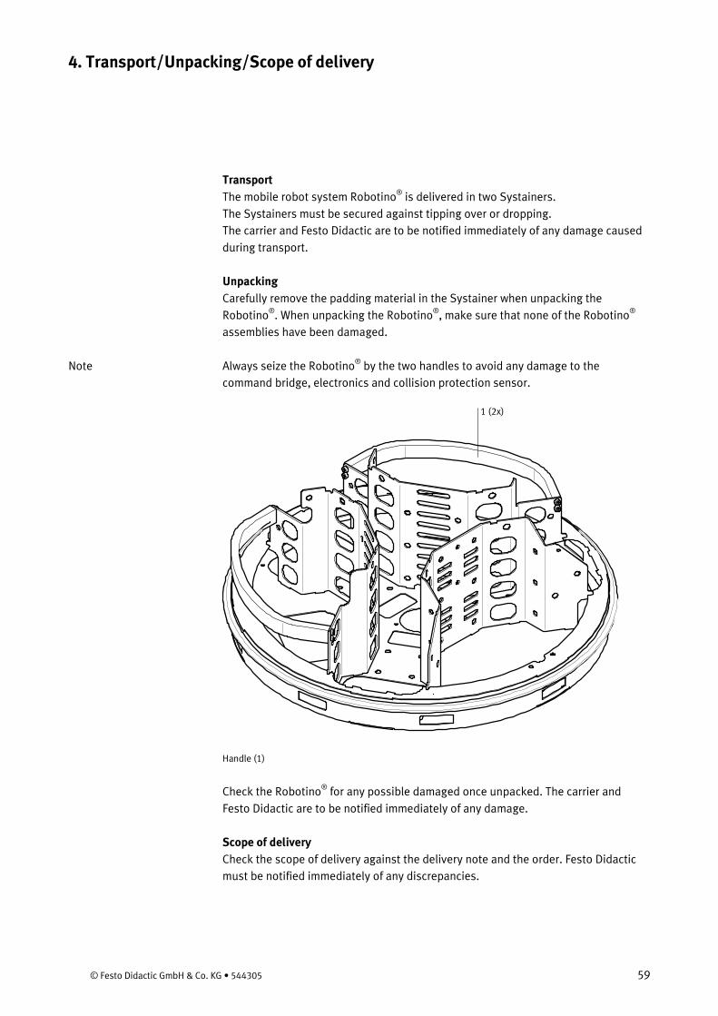
© Festo Didactic GmbH & Co. KG • 544305 59
Transport The mobile robot system Robotino®
The Systainers must be secured against tipping over or dropping. is delivered in two Systainers.
The carrier and Festo Didactic are to be notified immediately of any damage caused during transport. Unpacking Carefully remove the padding material in the Systainer when unpacking the Robotino®. When unpacking the Robotino®, make sure that none of the Robotino®
assemblies have been damaged.
Always seize the Robotino®
by the two handles to avoid any damage to the command bridge, electronics and collision protection sensor.
1 (2x)
Handle (1)
Check the Robotino®
for any possible damaged once unpacked. The carrier and Festo Didactic are to be notified immediately of any damage.
Scope of delivery Check the scope of delivery against the delivery note and the order. Festo Didactic must be notified immediately of any discrepancies.
4. Transport/Unpacking/Scope of delivery
Note
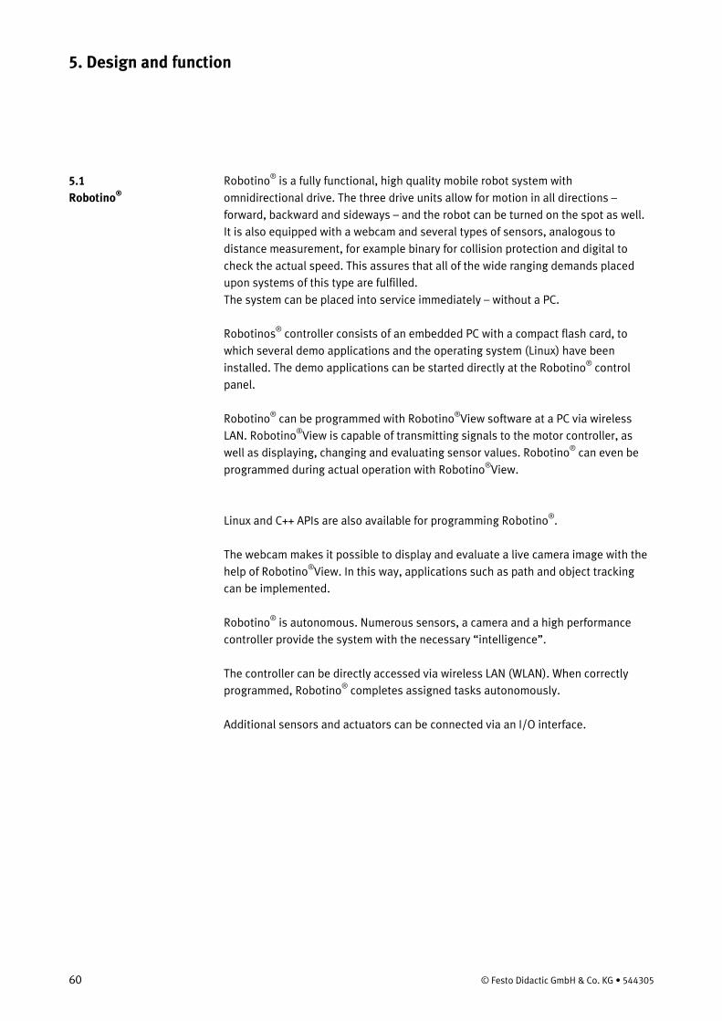
60 © Festo Didactic GmbH & Co. KG • 544305
Robotino®
is a fully functional, high quality mobile robot system with omnidirectional drive. The three drive units allow for motion in all directions – forward, backward and sideways – and the robot can be turned on the spot as well. It is also equipped with a webcam and several types of sensors, analogous to distance measurement, for example binary for collision protection and digital to check the actual speed. This assures that all of the wide ranging demands placed upon systems of this type are fulfilled. The system can be placed into service immediately – without a PC.
Robotinos® controller consists of an embedded PC with a compact flash card, to which several demo applications and the operating system (Linux) have been installed. The demo applications can be started directly at the Robotino®
control panel.
Robotino® can be programmed with Robotino®View software at a PC via wireless LAN. Robotino®View is capable of transmitting signals to the motor controller, as well as displaying, changing and evaluating sensor values. Robotino® can even be programmed during actual operation with Robotino®
View.
Linux and C++ APIs are also available for programming Robotino®
.
The webcam makes it possible to display and evaluate a live camera image with the help of Robotino®
View. In this way, applications such as path and object tracking can be implemented.
Robotino®
is autonomous. Numerous sensors, a camera and a high performance controller provide the system with the necessary “intelligence”.
The controller can be directly accessed via wireless LAN (WLAN). When correctly programmed, Robotino®
completes assigned tasks autonomously.
Additional sensors and actuators can be connected via an I/O interface.
5. Design and function
5.1 Robotino®
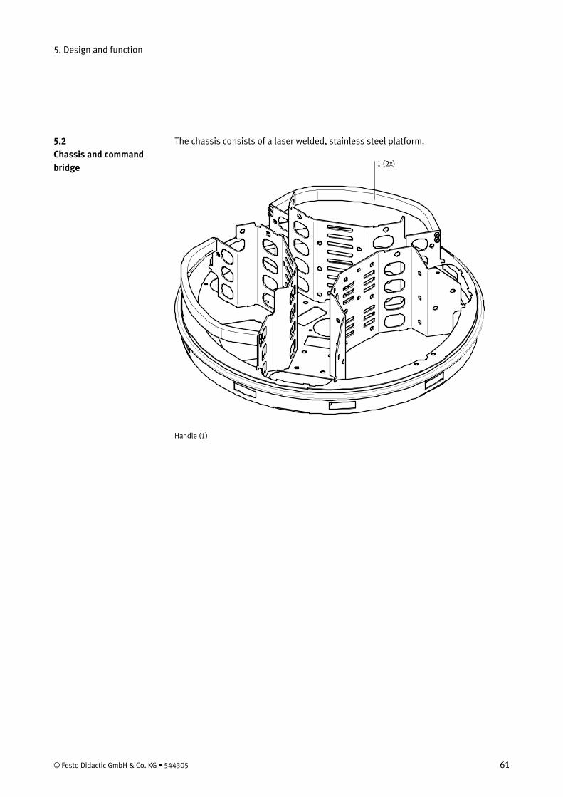
5. Design and function
© Festo Didactic GmbH & Co. KG • 544305 61
The chassis consists of a laser welded, stainless steel platform.
1 (2x)
Handle (1)
5.2 Chassis and command bridge

5. Design and function
62 © Festo Didactic GmbH & Co. KG • 544305
The rechargeable batteries, the drive units and the camera are mounted to the chassis, where the distance measuring sensors and the anti-collision sensor are also located. The chassis offers additional space and mounting options for other attachments, sensors and/or actuators.
3 (2x)
2 (3x) Drive unit (2) Battery (3)
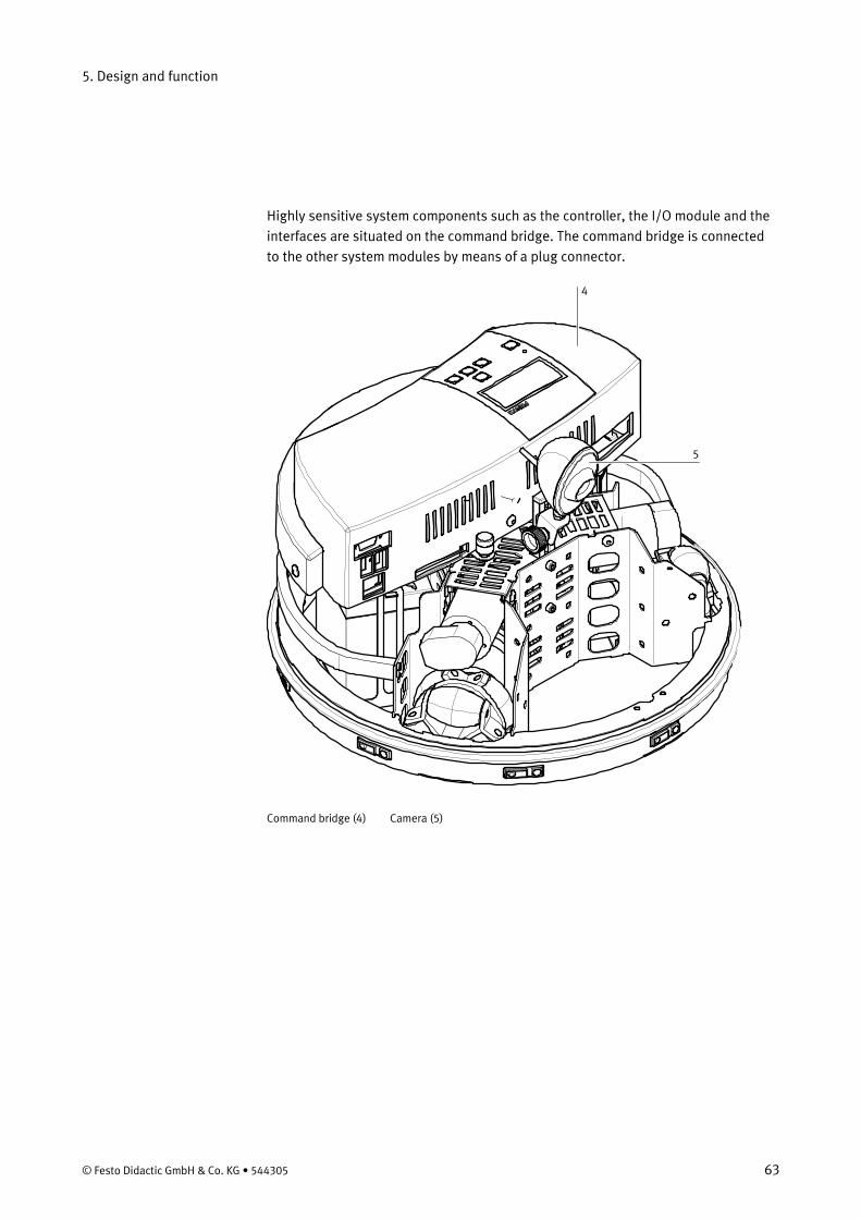
5. Design and function
© Festo Didactic GmbH & Co. KG • 544305 63
Highly sensitive system components such as the controller, the I/O module and the interfaces are situated on the command bridge. The command bridge is connected to the other system modules by means of a plug connector.
4
5
Command bridge (4) Camera (5)
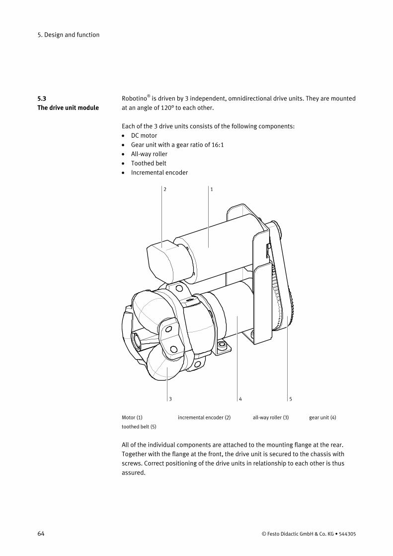
5. Design and function
64 © Festo Didactic GmbH & Co. KG • 544305
Robotino®
is driven by 3 independent, omnidirectional drive units. They are mounted at an angle of 120° to each other.
Each of the 3 drive units consists of the following components: • DC motor • Gear unit with a gear ratio of 16:1 • All-way roller • Toothed belt • Incremental encoder
12
3 4 5 Motor (1) incremental encoder (2) all-way roller (3) gear unit (4)
toothed belt (5)
All of the individual components are attached to the mounting flange at the rear. Together with the flange at the front, the drive unit is secured to the chassis with screws. Correct positioning of the drive units in relationship to each other is thus assured.
5.3 The drive unit module
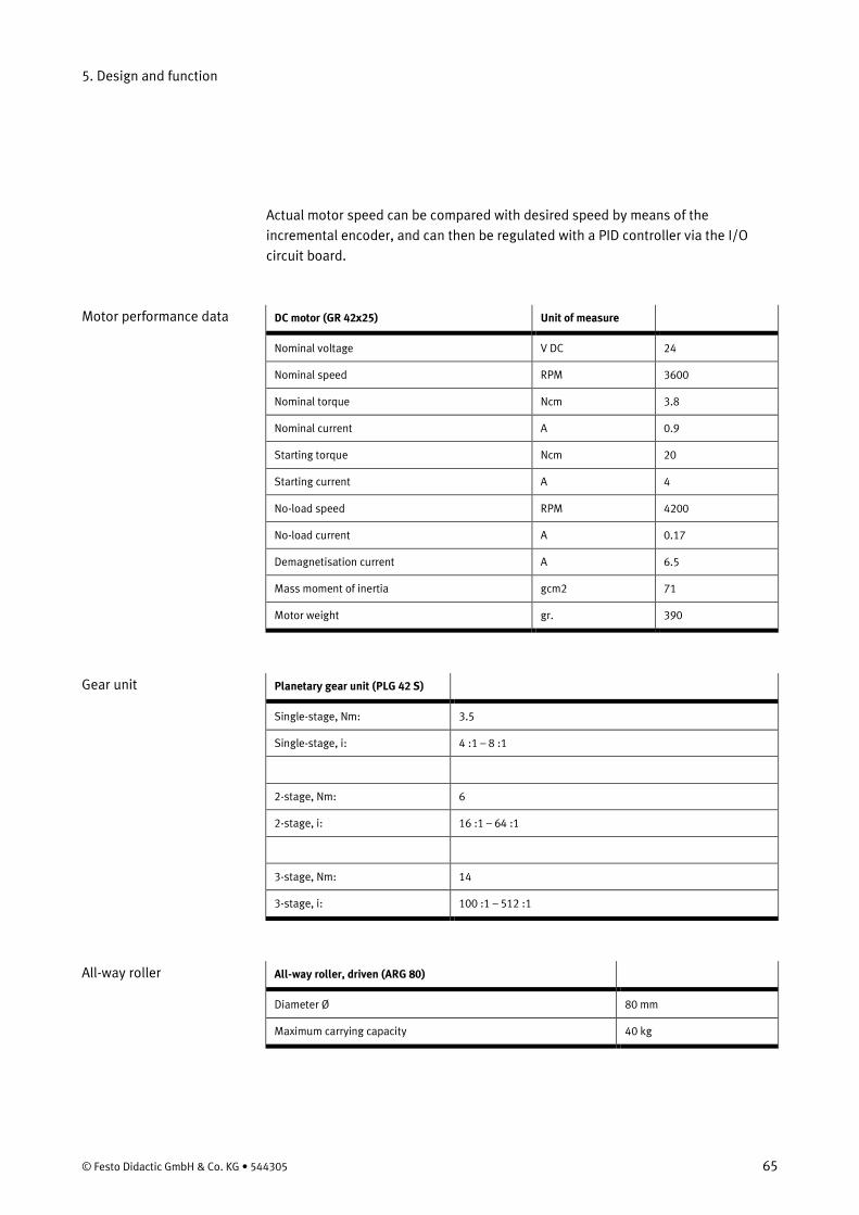
5. Design and function
© Festo Didactic GmbH & Co. KG • 544305 65
Actual motor speed can be compared with desired speed by means of the incremental encoder, and can then be regulated with a PID controller via the I/O circuit board.
DC motor (GR 42x25) Unit of measure
Nominal voltage V DC 24
Nominal speed RPM 3600
Nominal torque Ncm 3.8
Nominal current A 0.9
Starting torque Ncm 20
Starting current A 4
No-load speed RPM 4200
No-load current A 0.17
Demagnetisation current A 6.5
Mass moment of inertia gcm2 71
Motor weight gr. 390
Planetary gear unit (PLG 42 S)
Single-stage, Nm: 3.5
Single-stage, i: 4 :1 – 8 :1
2-stage, Nm: 6
2-stage, i: 16 :1 – 64 :1
3-stage, Nm: 14
3-stage, i: 100 :1 – 512 :1
All-way roller, driven (ARG 80)
Diameter Ø 80 mm
Maximum carrying capacity 40 kg
Motor performance data
Gear unit
All-way roller
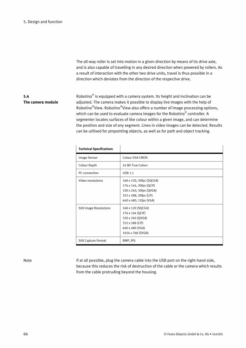
5. Design and function
66 © Festo Didactic GmbH & Co. KG • 544305
The all-way roller is set into motion in a given direction by means of its drive axle, and is also capable of travelling in any desired direction when powered by rollers. As a result of interaction with the other two drive units, travel is thus possible in a direction which deviates from the direction of the respective drive. Robotino® is equipped with a camera system. Its height and inclination can be adjusted. The camera makes it possible to display live images with the help of Robotino®View. Robotino®View also offers a number of image processing options, which can be used to evaluate camera images for the Robotino®
controller. A segmenter locates surfaces of like colour within a given image, and can determine the position and size of any segment. Lines in video images can be detected. Results can be utilised for pinpointing objects, as well as for path and object tracking.
Technical Specifications
Image Sensor Colour VGA CMOS
Colour Depth 24 Bit True Colour
PC-connection USB 1.1
Video resolutions 160 x 120, 30fps (SQCGA)
176 x 144, 30fps (QCIF)
320 x 240, 30fps (QVGA)
352 x 288, 30fps (CIF)
640 x 480, 15fps (VGA)
Still Image Resolutions 160 x 120 (SQCGA)
176 x 144 (QCIF)
320 x 240 (QVGA)
352 x 288 (CIF)
640 x 480 (VGA)
1024 x 768 (SVGA)
Still Capture Format BMP, JPG
If at all possible, plug the camera cable into the USB port on the right-hand side, because this reduces the risk of destruction of the cable or the camera which results from the cable protruding beyond the housing.
5.4 The camera module
Note
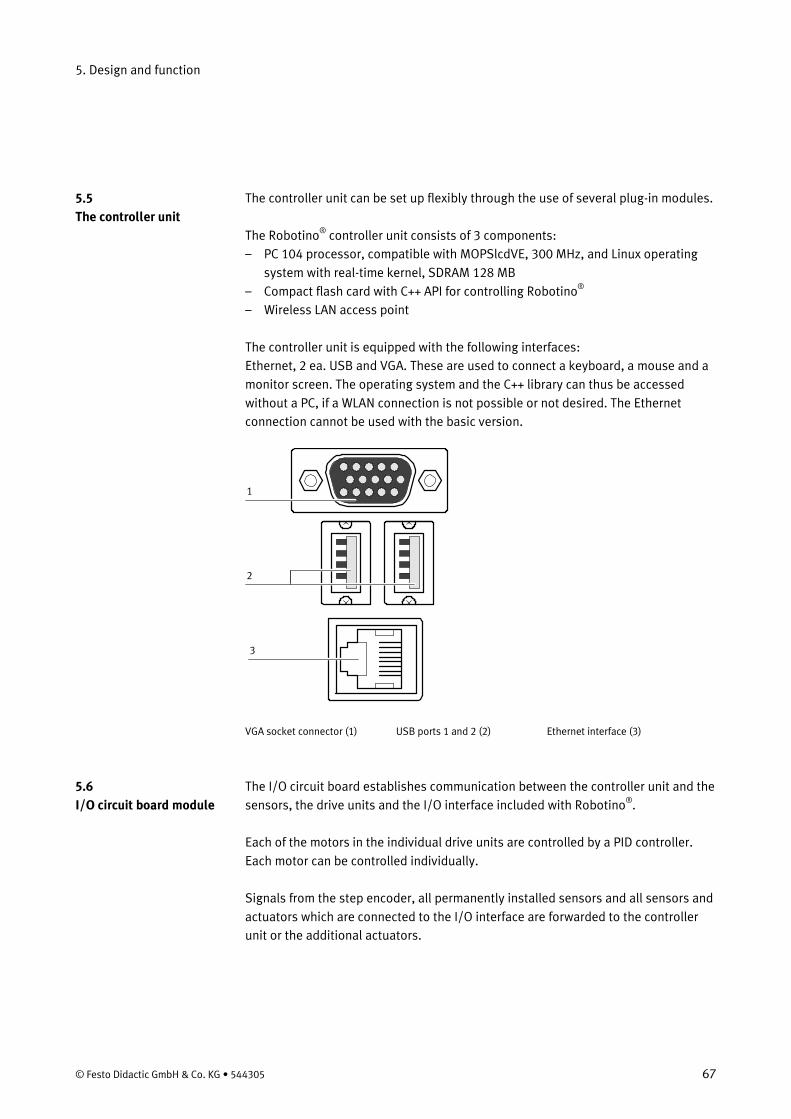
5. Design and function
© Festo Didactic GmbH & Co. KG • 544305 67
The controller unit can be set up flexibly through the use of several plug-in modules. The Robotino®
– PC 104 processor, compatible with MOPSlcdVE, 300 MHz, and Linux operating system with real-time kernel, SDRAM 128 MB
controller unit consists of 3 components:
– Compact flash card with C++ API for controlling Robotino– Wireless LAN access point
®
The controller unit is equipped with the following interfaces: Ethernet, 2 ea. USB and VGA. These are used to connect a keyboard, a mouse and a monitor screen. The operating system and the C++ library can thus be accessed without a PC, if a WLAN connection is not possible or not desired. The Ethernet connection cannot be used with the basic version.
1
2
3
VGA socket connector (1) USB ports 1 and 2 (2) Ethernet interface (3)
The I/O circuit board establishes communication between the controller unit and the sensors, the drive units and the I/O interface included with Robotino®
.
Each of the motors in the individual drive units are controlled by a PID controller. Each motor can be controlled individually. Signals from the step encoder, all permanently installed sensors and all sensors and actuators which are connected to the I/O interface are forwarded to the controller unit or the additional actuators.
5.5 The controller unit
5.6 I/O circuit board module
5. Design and function
68 © Festo Didactic GmbH & Co. KG • 544305
Power is supplied by two rechargeable 12 V batteries with a rating of 4 Ah. Both of the rechargeable batteries are mounted to the chassis. Robotino®
is supplied with 2 additional batteries and a battery charger. Two batteries can thus be recharged, while the other two are in use.
Sensors for measuring the distance to objects and detecting motor speed have been integrated into Robotino®
. An anti-collision sensor mounted around the circumference of the chassis signals contact with objects.
Robotino® is equipped with 9 infrared distance measuring sensors which are mounted in the chassis at an angle of 40° to one another. Robotino®
can scrutinise all surrounding areas for objects with these sensors. Each of the sensors can be queried individually via the I/O circuit board. Obstacles can thus be avoided, clearances can be maintained and bearings can be taken on a selected target. The sensors are capable of accurate or relative distance measurements to objects at distances of 4 to 30 cm. Sensor connection is especially simple including just one analogue output signal and supply power. The sensors’ evaluation electronics determine distance and read it out as an analogue signal.
The actual speed of each individual motor is measured in RPM by the incremental encoder. If actual motor speed deviates from the setpoint, it can be adjusted to match the target value by means of a PID controller whose parameters are configured with the help of Robotino®
View software.
The anti-collision sensor is comprised of a switching strip which is secured around the entire circumference of the chassis. A switching chamber is located inside a plastic profile. 2 conductive surfaces are situated inside the chamber, between which a given clearance is maintained. These surfaces are short circuited when even minimal pressure is applied to the strip. A reliably recognisable signal is thus transmitted to the controller unit. Collisions with objects at any point on the housing are detected and, for example, Robotino®
is brought to a standstill.
5.7 Power supply / battery charger
5.8 Sensors
Infrared distance measuring sensors
Incremental encoder
The anti-collision sensor
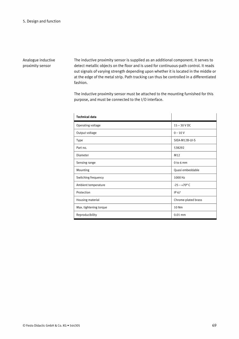
5. Design and function
© Festo Didactic GmbH & Co. KG • 544305 69
The inductive proximity sensor is supplied as an additional component. It serves to detect metallic objects on the floor and is used for continuous-path control. It reads out signals of varying strength depending upon whether it is located in the middle or at the edge of the metal strip. Path tracking can thus be controlled in a differentiated fashion. The inductive proximity sensor must be attached to the mounting furnished for this purpose, and must be connected to the I/O interface.
Technical data
Operating voltage 15 – 30 V DC
Output voltage 0 – 10 V
Type SIEA-M12B-UI-S
Part no. 538292
Diameter M12
Sensing range 0 to 6 mm
Mounting Quasi embeddable
Switching frequency 1000 Hz
Ambient temperature -25 – +70° C
Protection IP 67
Housing material Chrome-plated brass
Max. tightening torque 10 Nm
Reproducibility 0.01 mm
Analogue inductive proximity sensor
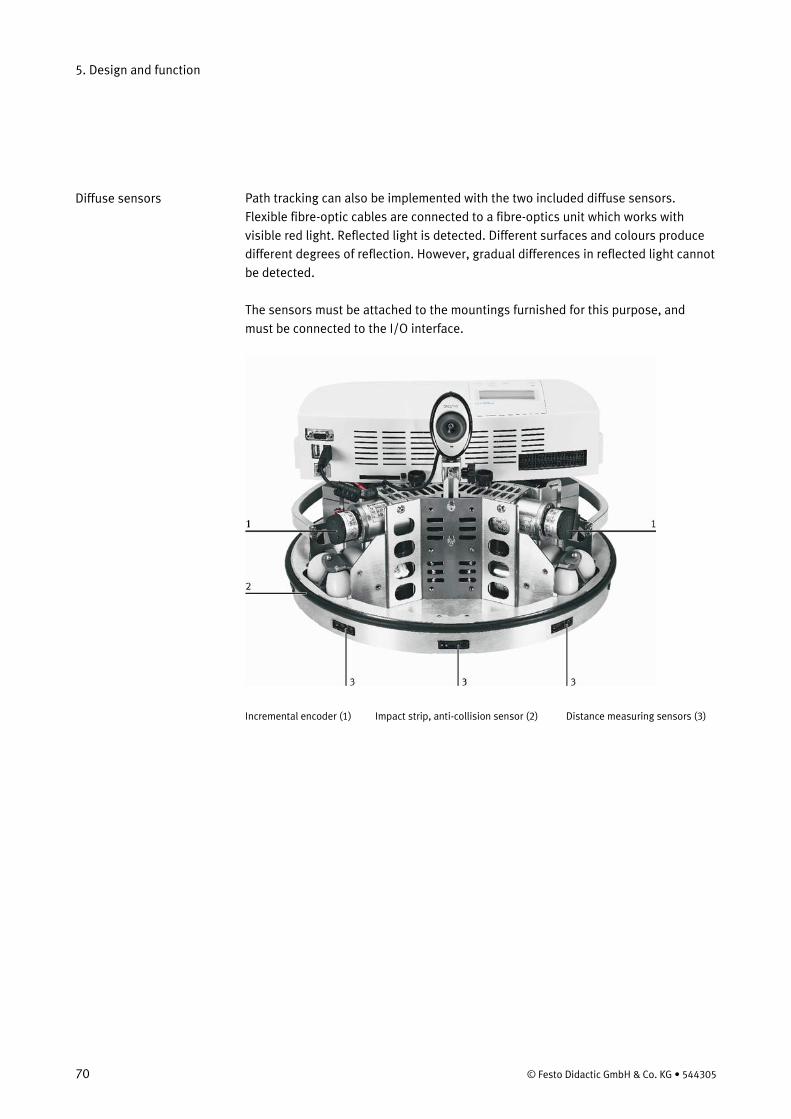
5. Design and function
70 © Festo Didactic GmbH & Co. KG • 544305
Path tracking can also be implemented with the two included diffuse sensors. Flexible fibre-optic cables are connected to a fibre-optics unit which works with visible red light. Reflected light is detected. Different surfaces and colours produce different degrees of reflection. However, gradual differences in reflected light cannot be detected. The sensors must be attached to the mountings furnished for this purpose, and must be connected to the I/O interface.
Incremental encoder (1) Impact strip, anti-collision sensor (2) Distance measuring sensors (3)
Diffuse sensors
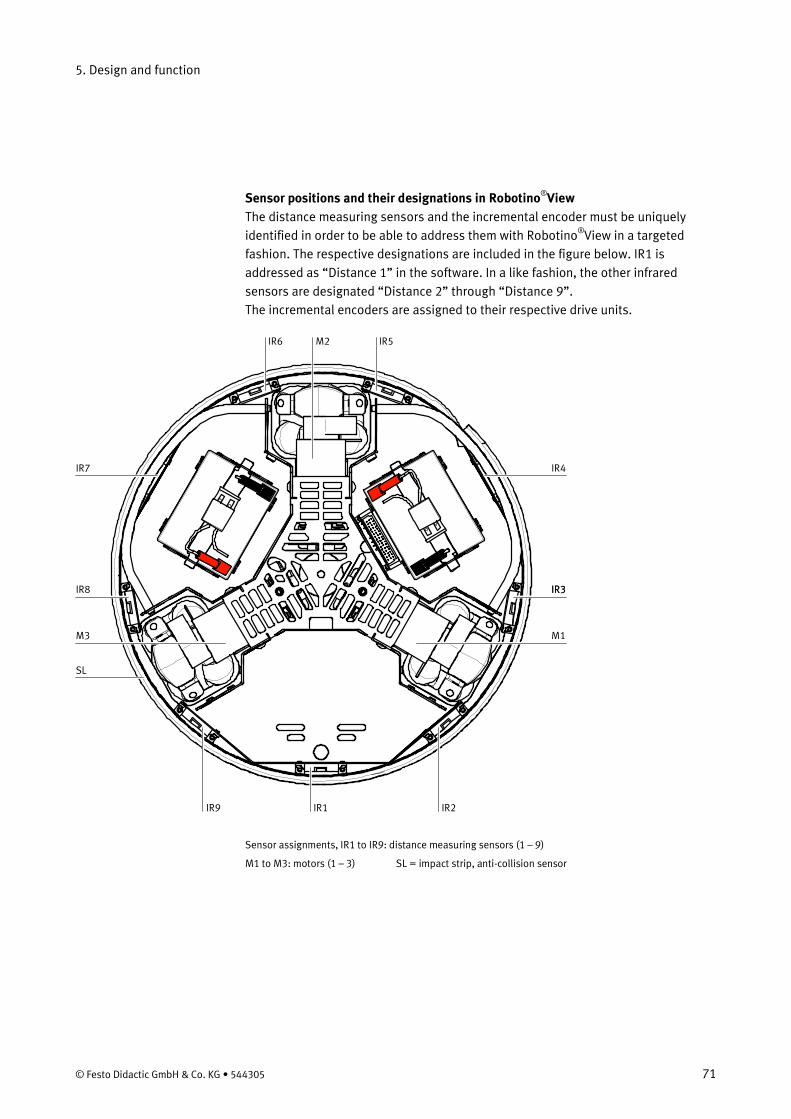
5. Design and function
© Festo Didactic GmbH & Co. KG • 544305 71
Sensor positions and their designations in Robotino®
The distance measuring sensors and the incremental encoder must be uniquely identified in order to be able to address them with Robotino
View
®
View in a targeted fashion. The respective designations are included in the figure below. IR1 is addressed as “Distance 1” in the software. In a like fashion, the other infrared sensors are designated “Distance 2” through “Distance 9”. The incremental encoders are assigned to their respective drive units.
IR6 IR5M2
IR4
IR3
M1
IR9 IR1 IR2
IR3
M3
IR8
SL
IR7
Sensor assignments, IR1 to IR9: distance measuring sensors (1 – 9)
M1 to M3: motors (1 – 3) SL = impact strip, anti-collision sensor
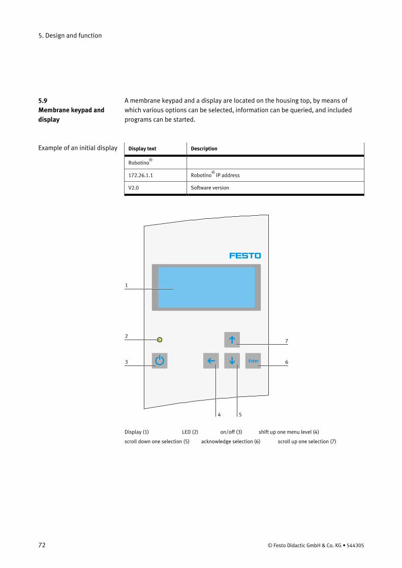
5. Design and function
72 © Festo Didactic GmbH & Co. KG • 544305
A membrane keypad and a display are located on the housing top, by means of which various options can be selected, information can be queried, and included programs can be started.
Display text Description
Robotino ®
172.26.1.1 Robotino®
V2.0
IP address
Software version
Enter
1
2
3 6
7
54 Display (1) LED (2) on/off (3) shift up one menu level (4)
scroll down one selection (5) acknowledge selection (6) scroll up one selection (7)
5.9 Membrane keypad and display
Example of an initial display
5. Design and function
© Festo Didactic GmbH & Co. KG • 544305 73
The wireless LAN access point is a component which allows for communication with the robot via a network address. – The access point features low current consumption. Power supply via the USB
port is possible. – The access point complies with the following standards: IEEE 802.11g and
802.11b. – It allows for transmission speeds of up to 54 Mb per second for 802-11g, and 11
Mb per second for 802.11b with a large transmission range (up to 100 m inside of buildings).
– It assures reliable network security with WEP encryption and WPA-PSK function. – It’s fast and simple to configure via the web management utility. The controller unit is equipped with a slot into which a PC card has already been inserted. This PC card contains the operating system, the functions libraries and the included programs. Updates can be easily installed by simply replacing the PC card. The slot for the PC card is located to the right of the controller unit interfaces. You can download updates from our homepage to your existing memory card free of charge.
5.10 Wireless LAN access point
5.11 The compact flash card
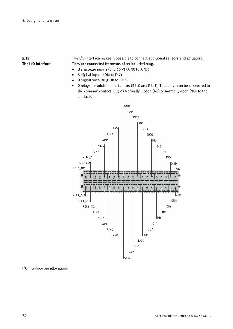
5. Design and function
74 © Festo Didactic GmbH & Co. KG • 544305
The I/O interface makes it possible to connect additional sensors and actuators. They are connected by means of an included plug. • 8 analogue inputs (0 to 10 V) (AIN0 to AIN7) • 8 digital inputs (DI0 to DI7) • 8 digital outputs (DO0 to DO7) • 2 relays for additional actuators (REL0 and REL1). The relays can be connected to
the common contact (CO) as Normally Closed (NC) or normally open (NO) to the contacts.
DO2
24V
24V
DI0
DI2
GND
DI1
DI3
DO0
DO124V
AIN5
AIN7
AIN4
AIN6
REL0_NC
REL0_CO
REL0_NO
DO3
GND
DO6
24V
24V
DI4
DI6
GND
DI5
DI7
DO4
DO524V
AIN1
AIN3
AIN0
AIN2
REL1_NC
REL1_CO
REL1_NO
DO7
GND
I/O interface pin allocations
5.12 The I/O interface
© Festo Didactic GmbH & Co. KG • 544305 75
Always jack up the Robotino® if you do not want to work with the Robotino® or would like to test individual functions! You can then easily check the functioning of sensors or activate actuators without fear of a collision. In this way, the Robotino®
is always close at hand and can remain connected to the charging station.
With the supplied device, you can jack up the Robotino® such that the Robotino® wheels are freely movable and do not come into contact with the ground. To do so, place the jacking device onto a stable and level surface with the rubber pads pointing upwards. Then position the Robotino® onto the rubber pads. The Robotino®
must be positioned onto the jack such as to ensure that the drive pinions are not located on any of the rubber pads.
Always hold the Robotino® at the chassis when transporting it. Lifting the Robotino® from the command bridge can cause extensive damage to the sensitive electronics. The front of the Robotino®
is where the distance sensor 1 and the mounting facility for the inductive sensor are located.
Any obstacles must extend as far as the ground since otherwise the collision protection sensor will not respond. The same applies in the case of the distance sensors. This is particularly important since otherwise damage may be caused to the Robotino®
.
Next, connect the battery charger to the appropriate cable of the batteries. The cable is located behind the drive unit M1. The plug is under the ring of the base group. Carefully pull this out and connect it to the charger by inserting the plug into the socket, making sure that the latching clamps of the charger cable is clipped in. To release the cable connection, you need to press the latching clamp and pull out the plug at the same time. Now switch on the Robotino®. Press the On/Off button until the LED lights up. The display switches on. On the display, 2 bars are displayed across the entire display width. The PC of the Robotino®
After approx. 30 seconds, the start display appears on the display. is now booting up.
The display shows for example the following: Robotino 172.26.1.1
®
6. Commissioning
6.1 Initial steps
Important notes
6.2 Switching On and Off
6. Commissioning
76 © Festo Didactic GmbH & Co. KG • 544305
The last line shows a bar indicating the state of charge of the batteries and displaying Robotino®
version: V 1.0
The Robotino®
is now ready for operation.
If none of the keys are actuated for 10 seconds, the illumination of the display is switched off in order to keep current consumption as low as possible during operation. To re-activate the display, press one of the arrow keys to switch on again. Do not press the Enter key for this so as to avoid an unwanted start of, for example, a demo program! Switching off Press the On/Off button until the LED is extinguished and then release the button. The Robotino®
is not switched off until the button is released.
Main menu Press the Enter key to access the main menu. In its original status the display is in English. It contains the following menu items: • Languages • State of charge • DEMOs • Network Using the Up and Down arrow keys, you can move the left (>) sentinel up or down. Press the Enter key to call up the relevant menu item or start the tagged demo program. Press the Left arrow key to exit from a menu to the next higher-order menu. Languages deutsch english français español
Note
6.3 The display functions
6. Commissioning
© Festo Didactic GmbH & Co. KG • 544305 77
State of charge This display informs you of the actual state of charge of the accumulators, the actual voltage and current. Bar display for state of charge Voltage: 23 V Current: 1.0 A DEMOs Circle Forward Quadrangle Roaming Follow line Network This menu displays the current IP address which can be changed. The cursor (head of the arrow) is moved to the right using the Enter key and to the left using the Left arrow key. The value of the individual numbers can be increased or reduced using the Up/Down arrow keys. To exit the menu again, move the Left arrow key to the first digit. To return to the main menu again, press the Left arrow key. Press the Enter key again at the last digit of the IP address to access the next display, the subnet mask. Proceed as in the case of the IP address. When you are on the last digit of the subnet mask your changes to the IP address and subnet mask will be copied by pressing the Enter key again. First, check the functioning of the demo programs in the jacked up condition in order to familiarise yourself with their functions. Select a demo program and start this by pressing the Enter key. Stop the programs by briefly pressing any one of the keys on the touch-sensitive keyboard or by pressing the bumper. The Robotino®
immediately stops in either case.
The Circle and Forward programs are subject to a time limit in that they automatically stop the Robotino®
after 10 seconds.
6.4 Testing the demo programs
6. Commissioning
78 © Festo Didactic GmbH & Co. KG • 544305
Circle The Robotino®
moves along a circular path Required space: A rectangle of a 1m x 1m Time limit: 10 seconds End program: See above
Forward The Robotino®
moves straight ahead Required space: A straight distance of 1 m Time limit: 10 seconds End program: See above
Quadrangle The Robotino®
moves along a rectangle and rotates around its own axis 1 m x 1m Time limit: None End program: See above
Roaming The Robotino® moves straight ahead and evades any obstacles in the way. Depending on the position of the obstacles, the Robotino®
changes its direction of travel in different ways. Required space: Any Time limit: None End program: See above.
Distance sensors 1, 2 and 9 are used to detect obstacles. This is why the program cannot be stopped via the bumper within the coverage range of these sensors as the Robotino®
takes evasive action.
Follow line The camera of the Robotino must be connected to the control unit via the USB interface for this program. Draw a line which is at least 5 cm wide on the floor, for example using the adhesive tape. The line must be in red, black or blue. Set the Robotino® onto the line so that it can detect the line and then start the program. The Robotino®
will follow the marked line.
Comment
6. Commissioning
© Festo Didactic GmbH & Co. KG • 544305 79
The ground on which the Robotino®
is to travel must be horizontal and level. In this way, the desired movements can be reliably executed. The ground must be clean and dry in order to avoid any damage to the mechanical and electronic components. You must release the cable of the charger prior to starting the program and stow it away in the chassis.
Depending on the condition of the ground, the required space specified above may vary. You must therefore select a sufficiently large clear area. The required space specified above represents a minimum requirement. Robotino can, among others, be graphically programmed with RobotinoView. We recommend using the installed demo program to get started with RobotinoView. You will find further information and examples for each function block in the RobotinoView context-sensitive help. With Version 2.0 and later, you can transfer RobotinoView programs (file extension .rvw2) to Robotino and execute them at the click of a mouse. Please make sure that you always have the current version of RobotinoView installed on your PC and Robotino (memory card). A WLAN connection must be established to enable you to control the Robotino® with Robotino®
View.
Since different WLAN hardware and software is available, it is not possible to describe the correct set-up and preparation of your WLANs in detail. Activate your WLAN. Your WLAN setting must permit the assignment of an IP address to the WLAN. Only then can the access point in the Robotino®
establish a connection to your network.
As a precaution, place the Robotino® onto the jacking device. Then switch on the Robotino®
and wait for the booting up process, which you can view on the display. Make a note of the IP address displayed. To be on the safe side, a label with the IP address is affixed to the underside of the command bridge.
Let your WLAN search for available networks. A network with the name Robotino®
x.x now appears in the list of available networks. If necessary, establish a connection to this network if this has not been effected via your network software.
The following network settings are a prerequisite for a successful connection: Automatically assign network code (SSID) Automatically source IP address Both settings must be switched on to be able to establish a connection to the Robotino®
6.5 Executing demo programs on solid ground
.
Notes
6.6 Controlling the Robotino® with Robotino®
6.7 Setting up a WLAN connection
View
6. Commissioning
80 © Festo Didactic GmbH & Co. KG • 544305
You can test the WLAN connection using 2 simple DOS commands or the Robotino®
View software.
The ping IP address command Start the MS-DOS prompt, which is in the start menu under Programs/Accessories. Click onto "Prompt". Alternatively, you can enter the command “cmd” under “execute” in the start menu. Now enter the „ping“ command in the prompt, together with the IP address you have read off the Robotino®
display, e.g. "ping 172.26.1.1"
You will receive the following messages if a WLAN connection exists: C:\>ping 172.26.1.1 Ping is executed for 172.26.1.1 with 32 bytes of data: Response from 172.26.1.1: Bytes=32 time=4ms TTL=64 Response from 172.26.1.1: Bytes=32 time=2ms TTL=64 Response from 172.26.1.1: Bytes=32 time=3ms TTL=64 Response from 172.26.1.1: Bytes=32 time=6ms TTL=64 Ping statistics for 172.26.1.1: Packages: Sent = 4, received = 4, lost = 0 (0% loss), Approx. time specifications in milliseconds: Minimum = 2ms, maximum = 6ms, mean value = 3ms The following message will be displayed in the absence of a connection to the Robotino®
:
Ping is executed for 172.26.1.1 with 32 bytes of data: Timeout of request. Timeout of request. Timeout of request. Timeout of request. Ping statistics for 172.26.1.1: Packages sent = 4, received = 0, lost = 4 (100% loss),
6.8 Testing the WLAN connection
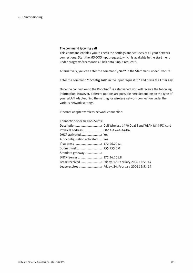
6. Commissioning
© Festo Didactic GmbH & Co. KG • 544305 81
The command ipconfig /all This command enables you to check the settings and statuses of all your network connections. Start the MS-DOS input request, which is available in the start menu under programs/accessories. Click onto "input request". Alternatively, you can enter the command „cmd“ in the Start menu under Execute. Enter the command "ipconfig /all" in the input request ">" and press the Enter key. Once the connection to the Robotino®
is established, you will receive the following information. However, different options are possible here depending on the type of your WLAN adapter. Find the setting for wireless network connection under the various network settings.
Ethernet adapter wireless network connection: Connection-specific DNS-Suffix: Description.............................. : Dell Wireless 1470 Dual Band WLAN Mini-PCI card Physical address ..................... : 00-14-A5-44-A4-D6 DHCP activated ....................... : Yes Autoconfiguration activated.... : Yes IP address ............................... : 172.26.201.1 Subnetmask ............................ : 255.255.0.0 Standard gateway ................... : DHCP-Server ........................... : 172.26.101.8 Lease received ........................ : Friday, 17. February 2006 13:51:14 Lease expires .......................... : Friday, 24. February 2006 13:51:14
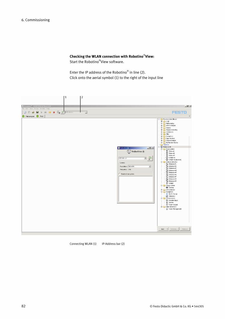
6. Commissioning
82 © Festo Didactic GmbH & Co. KG • 544305
Checking the WLAN connection with Robotino®
Start the RobotinoView:
®
View software.
Enter the IP address of the Robotino®
in line (2). Click onto the aerial symbol (1) to the right of the input line
Connecting WLAN (1) IP-Address bar (2)
6. Commissioning
© Festo Didactic GmbH & Co. KG • 544305 83
If there is no connection to the Robotino®
, a message is output after a certain time (45 s) and the message “connection refused” is displayed in the status bar on the bottom left. The aerial symbol is animated whilst the software is trying to establish a connection.
If the connection has been successfully set up, you can access all the software functions and all Robotino®
units directly.
By way of a simple example, now access the webcam of the Robotino®
. To do so, connect the webcam to the command bridge via the USB interface.
• Open a new worksheet by clicking onto the symbol (1) in the toolbar. • Now open the "Robotino®
• Drag the camera symbol (3a) onto the desktop by holding down the mouse button.
hardware" folder (2) by clicking it.
• Click onto the green arrow in the toolbar (4) to start the program • Open a window (5) with the actual camera image by double clicking the camera
symbol on the desktop (3b). By reducing the desktop, you can enlarge the window showing the camera image.
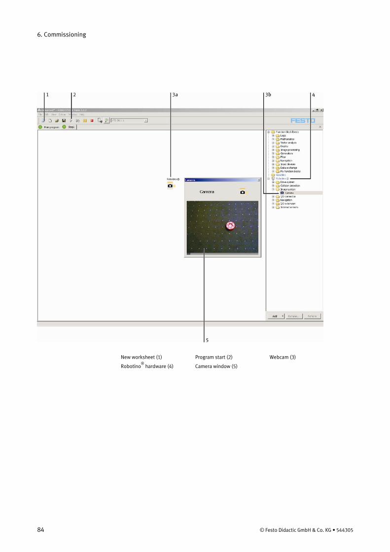
6. Commissioning
84 © Festo Didactic GmbH & Co. KG • 544305
New worksheet (1) Program start (2) Webcam (3)
Robotino®
hardware (4) Camera window (5)
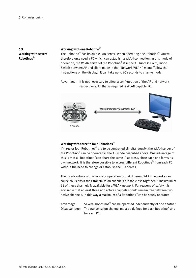
6. Commissioning
© Festo Didactic GmbH & Co. KG • 544305 85
Working with one RobotinoThe Robotino
® ® has its own WLAN server. When operating one Robotino® you will
therefore only need a PC which can establish a WLAN connection. In this mode of operation, the WLAN server of the Robotino®
is in the AP (Access Point) mode. Switch between AP and client mode in the "Network WLAN" menu (follow the instructions on the display). It can take up to 60 seconds to change mode.
Advantage: It is not necessary to effect a configuration of the AP and network respectively. All that is required is WLAN capable PC.
Working with three to four Robotinos®
If three or four Robotinos
® are to be controlled simultaneously, the WLAN server of the Robotino® can be operated in the AP mode described above. One advantage of this is that all Robotinos® can share the same IP address, since each one forms its own network. It is therefore possible to access different Robotinos®
from each PC without the need to change or establish the IP address.
The disadvantage of this mode of operation is that different WLAN networks can cause collisions if their transmission channels are too close together. A maximum of 11 of these channels is available for a WLAN network. For reasons of safety it is advisable that at least three non active channels should remain free between two active channels. In this way a maximum of 4 Robotinos®
can be safely operated.
Advantage: Several Robotinos®
Disadvantage: The transmission channel must be defined for each Robotino can be operated independently of one another.
®
and for each PC.
6.9 Working with several Robotinos®
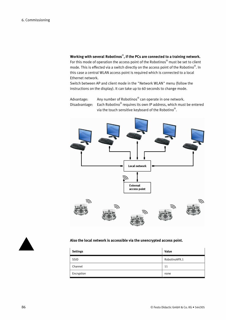
6. Commissioning
86 © Festo Didactic GmbH & Co. KG • 544305
Working with several Robotinos®
For this mode of operation the access point of the Robotinos, if the PCs are connected to a training network.
® must be set to client mode. This is effected via a switch directly on the access point of the Robotino®
Switch between AP and client mode in the "Network WLAN" menu (follow the instructions on the display). It can take up to 60 seconds to change mode.
. In this case a central WLAN access point is required which is connected to a local Ethernet network.
Advantage: Any number of Robotinos®
Disadvantage: Each Robotino can operate in one network.
® requires its own IP address, which must be entered via the touch sensitive keyboard of the Robotino®
.
Also the local network is accessible via the unencrypted access point.
Settings Value
SSID RobotinoAPX.1
Channel 11
Encryption none
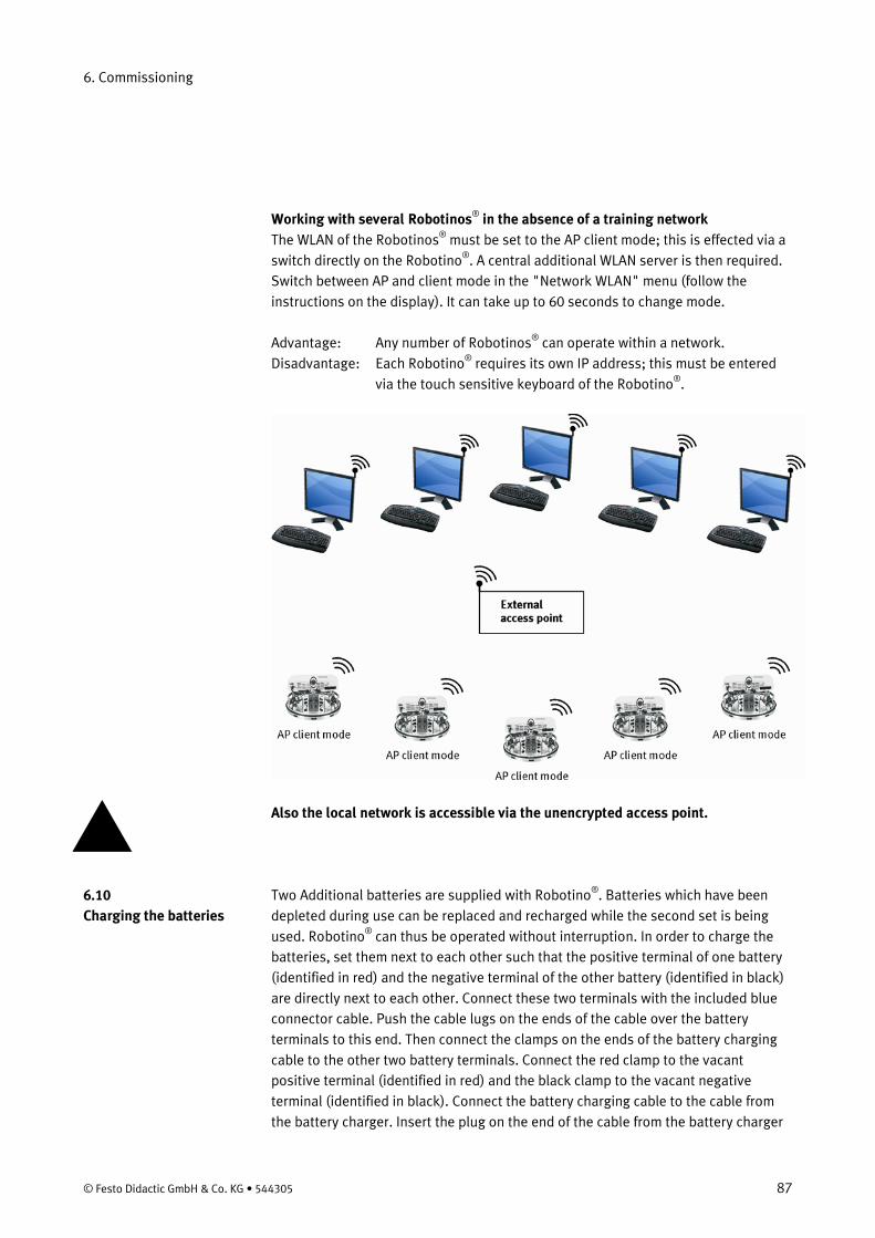
6. Commissioning
© Festo Didactic GmbH & Co. KG • 544305 87
Working with several Robotinos®
The WLAN of the Robotinos in the absence of a training network
® must be set to the AP client mode; this is effected via a switch directly on the Robotino®
Switch between AP and client mode in the "Network WLAN" menu (follow the instructions on the display). It can take up to 60 seconds to change mode.
. A central additional WLAN server is then required.
Advantage: Any number of Robotinos®
Disadvantage: Each Robotino can operate within a network.
® requires its own IP address; this must be entered via the touch sensitive keyboard of the Robotino®
.
Also the local network is accessible via the unencrypted access point. Two Additional batteries are supplied with Robotino®. Batteries which have been depleted during use can be replaced and recharged while the second set is being used. Robotino® can thus be operated without interruption. In order to charge the batteries, set them next to each other such that the positive terminal of one battery (identified in red) and the negative terminal of the other battery (identified in black) are directly next to each other. Connect these two terminals with the included blue connector cable. Push the cable lugs on the ends of the cable over the battery terminals to this end. Then connect the clamps on the ends of the battery charging cable to the other two battery terminals. Connect the red clamp to the vacant positive terminal (identified in red) and the black clamp to the vacant negative terminal (identified in black). Connect the battery charging cable to the cable from the battery charger. Insert the plug on the end of the cable from the battery charger
6.10 Charging the batteries
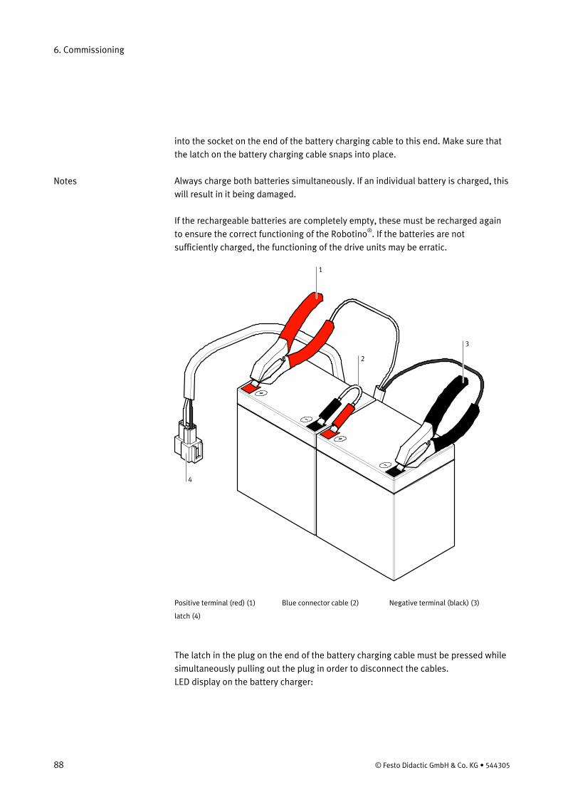
6. Commissioning
88 © Festo Didactic GmbH & Co. KG • 544305
into the socket on the end of the battery charging cable to this end. Make sure that the latch on the battery charging cable snaps into place. Always charge both batteries simultaneously. If an individual battery is charged, this will result in it being damaged. If the rechargeable batteries are completely empty, these must be recharged again to ensure the correct functioning of the Robotino®
. If the batteries are not sufficiently charged, the functioning of the drive units may be erratic.
4
1
3
2
Positive terminal (red) (1) Blue connector cable (2) Negative terminal (black) (3)
latch (4)
The latch in the plug on the end of the battery charging cable must be pressed while simultaneously pulling out the plug in order to disconnect the cables. LED display on the battery charger:
Notes
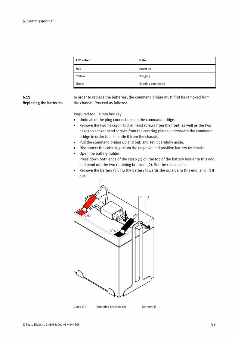
6. Commissioning
© Festo Didactic GmbH & Co. KG • 544305 89
LED colour State
Red power on
Yellow charging
Green charging completed
In order to replace the batteries, the command bridge must first be removed from the chassis. Proceed as follows: Required tool: 4 mm hex key • Undo all of the plug connections on the command bridge. • Remove the two hexagon socket head screws from the front, as well as the two
hexagon socket head screws from the centring plates underneath the command bridge in order to dismantle it from the chassis.
• Pull the command bridge up and out, and set it carefully aside. • Disconnect the cable lugs from the negative and positive battery terminals. • Open the battery holder.
Press down both ends of the clasp (1) on the top of the battery holder to this end, and bend out the two retaining brackets (2). Set the clasp aside.
• Remove the battery (3). Tip the battery towards the outside to this end, and lift it out.
1
2 3
Clasp (1) Retaining brackets (2) Battery (3)
6.11 Replacing the batteries
6. Commissioning
90 © Festo Didactic GmbH & Co. KG • 544305
Repeat the same procedure for the second battery. Repeat the procedure in reverse in order to install the replacement batteries. Observe the following points: • Make sure than none of the battery cables are trapped underneath the batteries,
or between the batteries and the battery holders. • Both of the battery terminals must point towards the centre of the Robotino®
The cables must be connected to the battery terminals as follows:
.
• The black cable must be connected to the negative terminal on the left (black). • The red cable which is secured to the clasp with the locking device must be
connected to the positive terminal at the right (red).
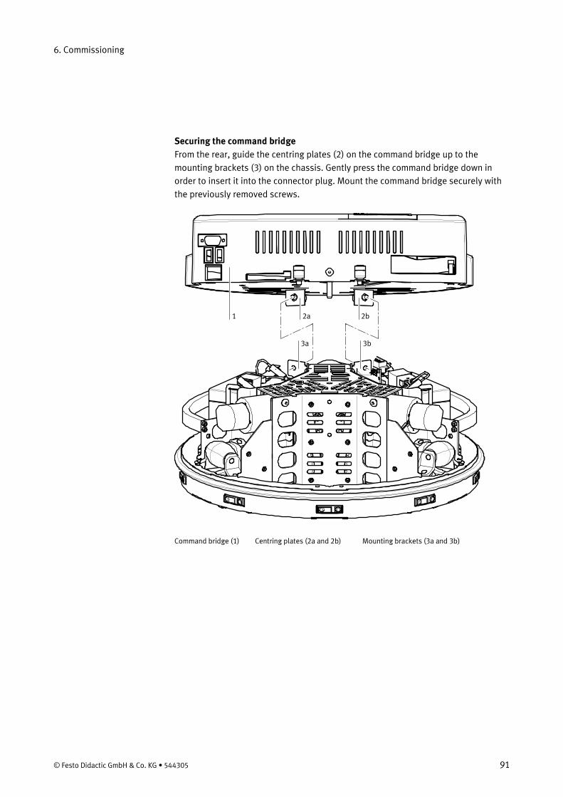
6. Commissioning
© Festo Didactic GmbH & Co. KG • 544305 91
Securing the command bridge From the rear, guide the centring plates (2) on the command bridge up to the mounting brackets (3) on the chassis. Gently press the command bridge down in order to insert it into the connector plug. Mount the command bridge securely with the previously removed screws.
1 2a 2b
3a 3b
Command bridge (1) Centring plates (2a and 2b) Mounting brackets (3a and 3b)
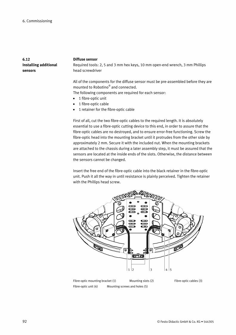
6. Commissioning
92 © Festo Didactic GmbH & Co. KG • 544305
Diffuse sensor Required tools: 2, 5 and 3 mm hex keys, 10 mm open-end wrench, 3 mm Phillips head screwdriver All of the components for the diffuse sensor must be pre-assembled before they are mounted to Robotino®
• 1 fibre-optic unit
and connected. The following components are required for each sensor:
• 1 fibre-optic cable • 1 retainer for the fibre-optic cable First of all, cut the two fibre-optic cables to the required length. It is absolutely essential to use a fibre-optic cutting device to this end, in order to assure that the fibre-optic cables are no destroyed, and to ensure error-free functioning. Screw the fibre-optic head into the mounting bracket until it protrudes from the other side by approximately 2 mm. Secure it with the included nut. When the mounting brackets are attached to the chassis during a later assembly step, it must be assured that the sensors are located at the inside ends of the slots. Otherwise, the distance between the sensors cannot be changed. Insert the free end of the fibre-optic cable into the black retainer in the fibre-optic unit. Push it all the way in until resistance is plainly perceived. Tighten the retainer with the Phillips head screw.
1 2 3 4 5 Fibre-optic mounting bracket (1) Mounting slots (2) Fibre-optic cables (3)
Fibre-optic unit (4) Mounting screws and holes (5)
6.12 Installing additional sensors
6. Commissioning
© Festo Didactic GmbH & Co. KG • 544305 93
Now mount the sensors to Robotinos®
chassis. First of all, secure the fibre-optic mounting bracket (1) to the bottom of the chassis by inserting two screws into the slot from underneath. The slots (2) at the front of the chassis for the mounting bracket have different functions. The long slot is used to secure the mounting bracket. The short slot acts as a window through which the light beam from the fibre-optic cable is allowed to pass. How far apart the fibre-optic cables (3) need to be mounted depends upon the width of the object to be detected.
Screw the fibre-optic mounting bracket to the chassis at the location shown in the photo. The mounting bracket is secured from underneath with the included screws (3 mm hexagon socket head screws). Secure both mounting brackets. Make sure that the fibre-optic head is in the correct slot! Now mount the fibre-optic unit (4) to the mounting plate in the Robotino®
. Secure it to the threaded holes provided to this end with the included screws (5).
Inductive analogue sensor The inductive analogue sensor is simply clamped into the permanently installed retainer. Loosen the knurled screw on the retainer to this end. Push the sensor, plug side up, into the hole provided for this purpose, hold it in the desired position and retighten the knurled screw. A cable with plug is furnished with the sensor. Plug the cable into the sensor and tighten the knurled nut. Observe the sensor’s working range! All of the sensors are connected to the I/O interface via the contact strip, and thus to the controller. Please refer to this documentation and the data sheets for the individual sensors regarding pin allocations for the I/O interface and wiring of the sensors.
Note
Note
6.13 Connecting the sensors
6. Commissioning
94 © Festo Didactic GmbH & Co. KG • 544305
Robotino has a large number of interfaces to standard languages. The demo programs in the menu, for example, are written in C++. The source code for these and many other demo programs is on the Robotino memory card and can be directly modified and compiled there. Different programming options are available to you via C++ to individually modify or expand the functions of the Robotino®
.
The CD-ROM provided offers C++ libraries for programming with MS Visual Studio 2005 or higher. These functions enable you to create your own programs to control communication with the Robotino® and the controller of the Robotino®
from the PC.
You will find the description of the functions and libraries in the comments within the program. The PC 104 of the Robotino® contains the same libraries, functions and source data for the Robotino®
sample programs in a Linux version. These can be edited with the Linux editor.
Basically two options are available for accessing the functions, libraries and sample programs on the PC 104. • One option is to access the Linux environment of the PC 104 using a terminal
program via a WLAN connection. • The other option is to connect the keyboard and screen directly to the PC 104
and to access the Linux operating system in this way. Access with the help of a terminal program The CD-ROM provided contains the Putty terminal program (putty_0_58.exe), with the following: 1. Establish a WLAN connection to the Robotino®
2. Start the putty_0_58.exe program. Enter the IP address of the Robotino.
® in the address line (host name or IP address), and click onto the Open button. The connection with the PC 104 of the Robotino®
3. Enter "robotino" as login name at the prompt. Confirm this with the Enter key. You are then requested to re-enter the password. Re-enter "robotino" and confirm your entry again.
is established.
6.14 C++ libraries
6. Commissioning
© Festo Didactic GmbH & Co. KG • 544305 95
Access via the system interface of the PC 104 1. Connect your keyboard via one of the two USB ports and a monitor to the VGA
interface of the PC 104. The connection is thus established. 2. Enter "robotino" as login name at the prompt. Confirm your entry via the Enter
key. You will then be prompted to enter the password. Re-enter "robotino" and confirm your entry again.
In both cases you will then be in the home directory of the user "robotino" of the Linux environment of the PC 104. From here you can access all programs, source codes and libraries. The directory "examples" contains the sample programs of the Robotino®
with their source data and a compiled version.
The program Circle Change into the directory /robotino/examples/circle and execute the program by entering "./circle" at the prompt. The command starts the already compiled sample program for moving along a circular path (incidentally the same as the one you can start via the display). By using an editor (e.g. nano), you can now edit the source code and retranslate it using Make.
Example
96 © Festo Didactic GmbH & Co. KG • 544305
All below mentioned documents are located in the" \Doc\EN" folder on the provided CD-ROM.
Unit Documents
Motors MotorGR2042(Diagrams).pdf
MotorGR2042(TechData).pdf
MotorGR2042(Description).pdf
Accumulators EN_Powerfit_S3124S(Datasheet).pdf
Distance sensors EN_Distance_Sensor_gp2d120.pdf
Analogue inductive sensor EN / DE / ES / FR
678411_Sensor_induktiv_analog_M12.pdf
Incremental encoder RE30(Data).pdf
RE30(Description).pdf
Diffuse sensor 369669_Fibre_optic_device.pdf
369682_Fibre_optic_cable_diffuse.pdf
165327_Fibre_Optic_Device_SOEG_L.pdf
165358_Fibre_Optic_Cable_Diffuse_SOEZ_RT.pdf
Collision sensor SafetyEdges.pdf
WLAN-Access Point WAP-0004(Manual).pdf
WAP-0004(DataSheet).pdf
Webcam, Windows Help File Webcam Live Users Guide English.chm
Fuses Fuses_Robotino®
Control unit
_Datasheet.pdf
Kontron_M_MOPSlcdSE_MOPSSE_PSTEM111.pdf
Current information and amendments to the technical documentation of the Robotino®
http://www.festo-didactic.com is available on the Internet at:
and http://www.openrobotino.org
7. Content of the CD-ROM / Appendix
7.1 Operating instructions and Data sheets
Updates
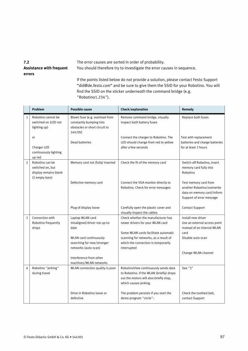
© Festo Didactic GmbH & Co. KG • 544305 97
The error causes are sorted in order of probability. You should therefore try to investigate the error causes in sequence. If the points listed below do not provide a solution, please contact Festo Support “[email protected]“ and be sure to give them the SSID for your Robotino. You will find the SSID on the sticker underneath the command bridge (e.g. "Robotino1.234").
Problem Possible cause Check/explanation Remedy
1 Robotino cannot be
switched on (LED not
lighting up)
or
Charger LED
continuously lighting
up red
Blown fuse (e.g. overload from
constantly bumping into
obstacles or short circuit to
24V/0V)
Dead batteries
Remove command bridge, visually
inspect both battery fuses
Connect the charger to Robotino. The
LED should change from red to yellow
after a few seconds
Replace both fuses
Test with replacement
batteries and charge batteries
for at least 2 hours
2 Robotino can be
switched on, but
display remains blank
(2 empty bars)
Memory card not (fully) inserted
Defective memory card
Plug of display loose
Check the fit of the memory card
Connect the VGA monitor directly to
Robotino. Check for error messages
Carefully open the plastic cover and
visually inspect the cables
Switch off Robotino, insert
memory card fully into
Robotino
Test memory card from
another Robotino/overwrite
data on memory card/inform
Support of error message
Contact Support
3 Connection with
Robotino frequently
drops
Laptop WLAN card
misaligned/driver not up-to-
date
WLAN card continuously
searching for new/stronger
networks (auto-scan)
Interference from other
machines/WLAN networks
Check whether the manufacturer has
newer drivers for your WLAN card
Some WLAN cards facilitate automatic
scanning for networks, as a result of
which the connection is temporarily
interrupted
Install new driver
Use an external access point
instead of an internal WLAN
card
Disable auto-scan
Change WLAN channel
4 Robotino "jerking"
during travel
WLAN connection quality is poor
Drive in Robotino loose or
defective
RobotinoView continuously sends data
to Robotino. If the WLAN (briefly) drops
out the motors will also briefly stop,
which causes jerking.
The problem persists if you start the
demo program "circle":
See "3"
Check the toothed belt,
contact Support
7.2 Assistance with frequent errors
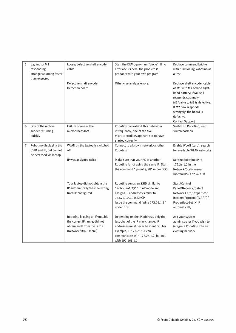
98 © Festo Didactic GmbH & Co. KG • 544305
5 E.g. motor M1
responding
strangely/turning faster
than expected
Loose/defective shaft encoder
cable
Defective shaft encoder
Defect on board
Start the DEMO program "circle". If no
error occurs here, the problem is
probably with your own program
Otherwise analyse errors:
Replace command bridge
with functioning Robotino as
a test.
Replace shaft encoder cable
of M1 with M2 behind right-
hand battery: if M1 still
responds strangely,
M1/cable to M1 is defective.
If M2 now responds
strangely, the board is
defective.
Contact Support
6 One of the motors
suddenly turning
quickly
Failure of one of the
microprocessors
Robotino can exhibit this behaviour
infrequently; one of the five
microcontrollers appears not to have
started correctly
Switch off Robotino, wait,
switch back on
7 Robotino displaying the
SSID and IP, but cannot
be accessed via laptop
WLAN on the laptop is switched
off
IP was assigned twice
Your laptop did not obtain the
IP automatically/has the wrong
fixed IP configured
Robotino is using an IP outside
the correct IP range/did not
obtain an IP from the DHCP
(Network/DHCP menu)
Connect to a known network/another
Robotino
Make sure that your PC or another
Robotino is not using the same IP. Start
the command "ipconfig/all" under DOS
Robotino sends an SSID similar to
"Robotino1.234" in AP mode and
assigns IP addresses similar to
172.26.100.1 as DHCP
Issue the command "ping 172.26.1.1"
under DOS
Depending on the IP address, only the
last digit of the IP may change. IP
addresses must never be identical. For
example, IP 172.26.1.1 can
communicate with 172.26.1.2, but not
with 192.168.1.1
Enable WLAN (card), search
for available WLAN networks
Set the Robotino IP to
172.26.1.2 in the
Network/Static menu
(normal IP= 172.26.1.1)
Start/Control
Panel/Network/Select
Network Card/Properties/
Internet Protocol (TCP/IP)/
Properties/Get [X] IP
automatically
Ask your system
administrator if you wish to
integrate Robotino into an
existing network
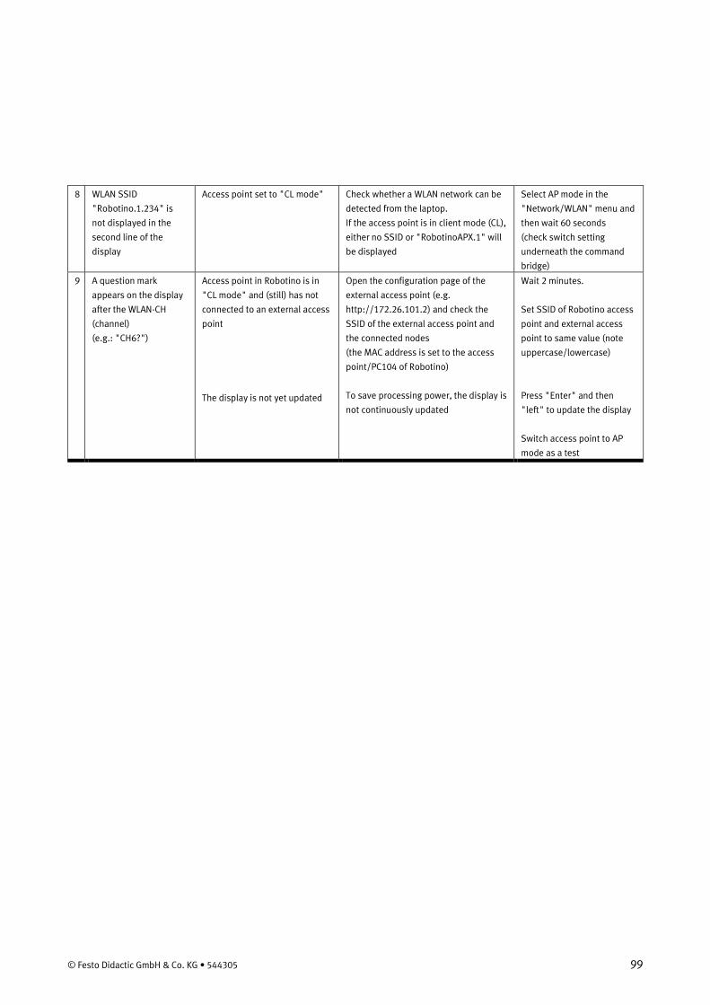
© Festo Didactic GmbH & Co. KG • 544305 99
8 WLAN SSID
"Robotino.1.234" is
not displayed in the
second line of the
display
Access point set to "CL mode"
Check whether a WLAN network can be
detected from the laptop.
If the access point is in client mode (CL),
either no SSID or "RobotinoAPX.1" will
be displayed
Select AP mode in the
"Network/WLAN" menu and
then wait 60 seconds
(check switch setting
underneath the command
bridge)
9 A question mark
appears on the display
after the WLAN-CH
(channel)
(e.g.: "CH6?")
Access point in Robotino is in
"CL mode" and (still) has not
connected to an external access
point
The display is not yet updated
Open the configuration page of the
external access point (e.g.
http://172.26.101.2) and check the
SSID of the external access point and
the connected nodes
(the MAC address is set to the access
point/PC104 of Robotino)
To save processing power, the display is
not continuously updated
Wait 2 minutes.
Set SSID of Robotino access
point and external access
point to same value (note
uppercase/lowercase)
Press "Enter" and then
"left" to update the display
Switch access point to AP
mode as a test
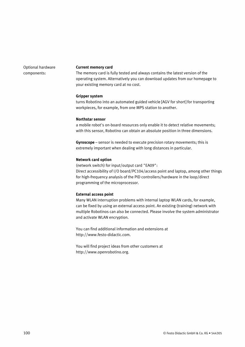
100 © Festo Didactic GmbH & Co. KG • 544305
Current memory card The memory card is fully tested and always contains the latest version of the operating system. Alternatively you can download updates from our homepage to your existing memory card at no cost. Gripper system turns Robotino into an automated guided vehicle [AGV for short] for transporting workpieces, for example, from one MPS station to another. Northstar sensor a mobile robot's on-board resources only enable it to detect relative movements; with this sensor, Robotino can obtain an absolute position in three dimensions. Gyroscope – sensor is needed to execute precision rotary movements; this is extremely important when dealing with long distances in particular. Network card option (network switch) for input/output card "EA09": Direct accessibility of I/O board/PC104/access point and laptop, among other things for high-frequency analysis of the PID controllers/hardware in the loop/direct programming of the microprocessor. External access point Many WLAN interruption problems with internal laptop WLAN cards, for example, can be fixed by using an external access point. An existing (training) network with multiple Robotinos can also be connected. Please involve the system administrator and activate WLAN encryption. You can find additional information and extensions at http://www.festo-didactic.com. You will find project ideas from other customers at http://www.openrobotino.org.
Optional hardware components: