Embed Size (px)
Citation preview
1
ISTRUZIONI INSTRUCTIONS ANWEISUNGEN INSTRUCTIONS INSTRUCCIONES
TERMINALI ANTERIORI PROLUNGATI PER INTERRUTTORE FISSOEXTENDED FRONT TERMINALS FOR FIXED CIRCUIT-BREAKER
VERLÄNGERTE VORDERSEITIGE ANSCHLÜSSE FÜR FESTEN LEISTUNGSSCHALTERPRISES AVANT PROLONGEES POUR DISJONCTEUR FIXE
CONEXIONES ANTERIORES PROLUNGADAS PARA INTERRUPTOR FIJO
KIT
ABB SACE
601778/294 L0547
SACE S6SACE S7
POS.ITEMPOS.POS.POS.
2-6
8-9
10
11
CONTENUTOCONTENTSINHALTCONTENUCONTENIDO
Terminali prolungatiExtended terminalsVerlängerte AnschlüssePrises prolongéesConexiones prolungadas
Terminali prolungati divaricatiSplayed extended terminalsVerlängerte V-förmige AnschlüssePrises prolongées écartéesTerminal prolongado separado
ViteScrewSchraubeVisTornillo
RosettaWasherUnterlegscheibeRondelleArandela
QUANTITA’QUANTITYANZAHLQUANTITECANTIDAD
630
800
22
S6 S7
SACE Isomax S
N.B. Le viti (10) e le rosette (11) sono da utilizzare solo per i terminali (9) dell'interruttore S7N.B. The screws (10) and washers (11) must only be used for the terminals (9) of the S7 circuit-breakerAnm. Die Schrauben (10) und Unterlegscheiben (11) sind nur für die Anschlüsse (9) des Leistungsschalters
S7 zu verwendenN.B. Les vis (10) et les rondelles (11) ne doivent être utilisées que pour les prises (9) du disjoncteur S7N.B. Los tornillos (10) y las arandelas (11) sólo se deben utilizar para los terminales (9) del interruptor S7
3 POL 4 POL
3 4
3 4
2 2
2 2
69
8
1011
2
ISTRUZIONI INSTRUCTIONS ANWEISUNGEN INSTRUCTIONS INSTRUCCIONES
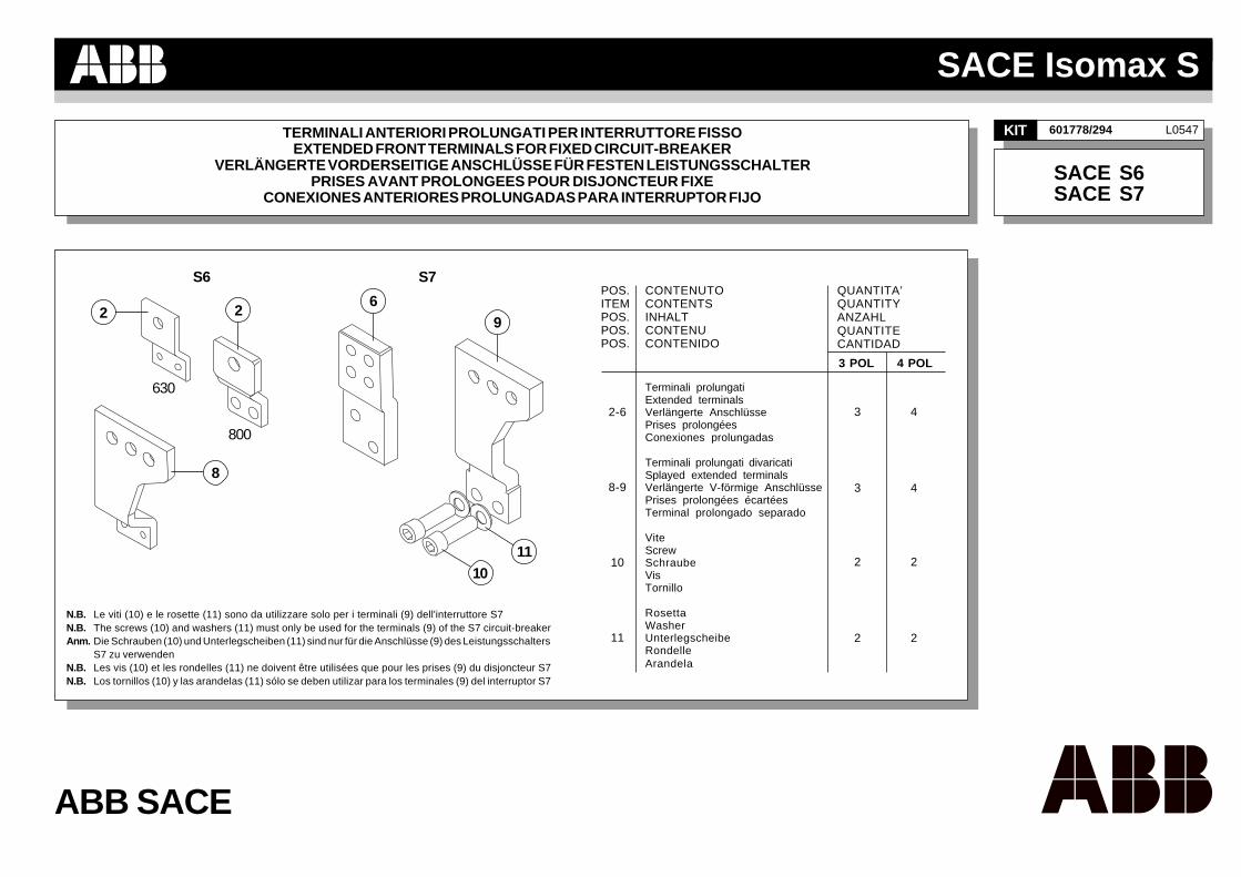
ARimuovere le viti (1) e le relative rosette,dai terminali anteriori dell'interruttore.
ARemove the screws (1) and the relevantwashers from the front terminals of thecircuit-breaker.
ADie Schrauben (1) und die entsprechendenUnterlegscheiben von den vorderseitigenAnschlüssen des Leistungsschalters ent-fernen.
AEnlever les vis (1) et les rondelles desprises avant du disjoncteur.
AQuitar los tornillos (1) y sus correspondien-tes arandelas, de las conexiones anterio-res del interruptor.
A B
Interruttori SACE Isomax S6 Leistungsschalter SACE Isomax S6 Disjoncteurs SACE Isomax S6 Interruptores SACE Isomax S6
BPosizionare il terminale prolungato (2) o(8) sul terminale anteriore (3) dell'interrut-tore.Bloccare il terminale prolungato (2) me-diante le viti (4) e le rosette (5). Applicareuna coppia di serraggio pari a 9 Nm.Ripetere le stesse operazioni per ognipolo dell'interruttore.Per il posizionamento dei terminali divari-cati (8) vedi fig. F pag. 4.
BPut the extended terminal (2) or (8) on thefront terminal (3) of the circuit-breaker.Fix the extended terminal (2) by using thescrews (4) and the washers (5). Apply a9 Nm tightening torque.Repeat the same operations for each poleof the circuit-breaker.See Figure F page 4 for how to position thesplayed terminals (8).
BDen verlängerten Anschluss (2) oder (8)auf den vorderseitigen Anschluss (3) desLeistungsschalters positionieren. Denverlängerten Anschluss (2) durch dieSchrauben (4) und die Unterlegscheiben(5) befestigen. Ein Drehmoment von 9 Nmanwenden.Die gleichen Arbeitsgänge für jeden Poldes Leistungsschalters wiederholen. Fürdie Anordnung der V-förmigen Anschlüs-se (8) siehe Abb. F auf S. 4.
BPositionner la prise prolongée (2) ou (8)sur la prise avant (3) du disjoncteur.Bloquer la prise prolongée (2) à l’aide desvis (4) et des rondelles (5). Appliquer uncouple de serrage de 9 Nm.Répéter les mêmes opérations pour cha-que pôle du disjoncteur.Pour le positionnement des prises écar-tées (8), voir fig. F page 4.
BColocar la conexión prolongada (2) o (8)en la conexión anterior (3) del interruptor.Bloquear la conexión prolongada (2) me-diante el tornillo (4) y las arandelas (5).Aplicar un par de torsión de 9 Nm. Repetirlas mismas operaciones para cada polodel interruptor.Para el posicionamiento de los terminalesseparados (8), véase fig. F pág. 4.
13 2
4 5
SACE Isomax S6 circuit-breaker
8
3
ISTRUZIONI INSTRUCTIONS ANWEISUNGEN INSTRUCTIONS INSTRUCCIONES
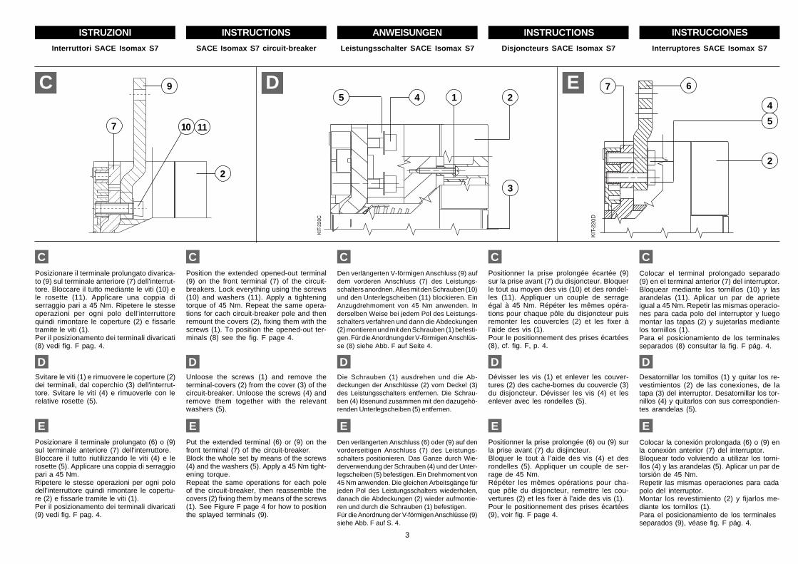
CPosizionare il terminale prolungato divarica-to (9) sul terminale anteriore (7) dell'interrut-tore. Bloccare il tutto mediante le viti (10) ele rosette (11). Applicare una coppia diserraggio pari a 45 Nm. Ripetere le stesseoperazioni per ogni polo dell'interruttorequindi rimontare le coperture (2) e fissarletramite le viti (1).Per il posizionamento dei terminali divaricati(8) vedi fig. F pag. 4.
CPosition the extended opened-out terminal(9) on the front terminal (7) of the circuit-breakers. Lock everything using the screws(10) and washers (11). Apply a tighteningtorque of 45 Nm. Repeat the same opera-tions for cach circuit-breaker pole and thenremount the covers (2), fixing them with thescrews (1). To position the opened-out ter-minals (8) see the fig. F page 4.
CDen verlängerten V-förmigen Anschluss (9) aufdem vorderen Anschluss (7) des Leistungs-schalters anordnen. Alles mit den Schrauben (10)und den Unterlegscheiben (11) blockieren. EinAnzugdrehmoment von 45 Nm anwenden. Inderselben Weise bei jedem Pol des Leistungs-schalters verfahren und dann die Abdeckungen(2) montieren und mit den Schrauben (1) befesti-gen. Für die Anordnung der V-förmigen Anschlüs-se (8) siehe Abb. F auf Seite 4.
CPositionner la prise prolongée écartée (9)sur la prise avant (7) du disjoncteur. Bloquerle tout au moyen des vis (10) et des rondel-les (11). Appliquer un couple de serrageégal à 45 Nm. Répéter les mêmes opéra-tions pour chaque pôle du disjoncteur puisremonter les couvercles (2) et les fixer àl’aide des vis (1).Pour le positionnement des prises écartées(8), cf. fig. F, p. 4.
CColocar el terminal prolongado separado(9) en el terminal anterior (7) del interruptor.Bloquear mediante los tornillos (10) y lasarandelas (11). Aplicar un par de aprieteigual a 45 Nm. Repetir las mismas operacio-nes para cada polo del interruptor y luegomontar las tapas (2) y sujetarlas mediantelos tornillos (1).Para el posicionamiento de los terminalesseparados (8) consultar la fig. F pág. 4.
C D
DSvitare le viti (1) e rimuovere le coperture (2)dei terminali, dal coperchio (3) dell'interrut-tore. Svitare le viti (4) e rimuoverle con lerelative rosette (5).
DUnloose the screws (1) and remove theterminal-covers (2) from the cover (3) of thecircuit-breaker. Unloose the screws (4) andremove them together with the relevantwashers (5).
DDie Schrauben (1) ausdrehen und die Ab-deckungen der Anschlüsse (2) vom Deckel (3)des Leistungsschalters entfernen. Die Schrau-ben (4) lösenund zusammen mit den dazugehö-renden Unterlegscheiben (5) entfernen.
DDévisser les vis (1) et enlever les couver-tures (2) des cache-bornes du couvercle (3)du disjoncteur. Dévisser les vis (4) et lesenlever avec les rondelles (5).
DDesatornillar los tornillos (1) y quitar los re-vestimientos (2) de las conexiones, de latapa (3) del interruptor. Desatornillar los tor-nillos (4) y quitarlos con sus correspondien-tes arandelas (5).
5 4 1 2
3
67
5
2
4
Interruttori SACE Isomax S7 Leistungsschalter SACE Isomax S7 Disjoncteurs SACE Isomax S7 Interruptores SACE Isomax S7SACE Isomax S7 circuit-breaker
E
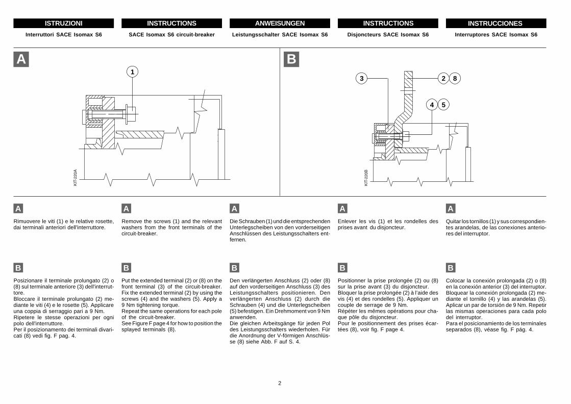
EPosizionare il terminale prolungato (6) o (9)sul terminale anteriore (7) dell’interruttore.Bloccare il tutto riutilizzando le viti (4) e lerosette (5). Applicare una coppia di serraggiopari a 45 Nm.Ripetere le stesse operazioni per ogni polodell’interruttore quindi rimontare le copertu-re (2) e fissarle tramite le viti (1).Per il posizionamento dei terminali divaricati(9) vedi fig. F pag. 4.
EPut the extended terminal (6) or (9) on thefront terminal (7) of the circuit-breaker.Block the whole set by means of the screws(4) and the washers (5). Apply a 45 Nm tight-ening torque.Repeat the same operations for each poleof the circuit-breaker, then reassemble thecovers (2) fixing them by means of the screws(1). See Figure F page 4 for how to positionthe splayed terminals (9).
EDen verlängerten Anschluss (6) oder (9) auf denvorderseitigen Anschluss (7) des Leistungs-schalters positionieren. Das Ganze durch Wie-derverwendung der Schrauben (4) und der Unter-legscheiben (5) befestigen. Ein Drehmoment von45 Nm anwenden. Die gleichen Arbeitsgänge fürjeden Pol des Leistungsschalters wiederholen,danach die Abdeckungen (2) wieder aufmontie-ren und durch die Schrauben (1) befestigen.Für die Anordnung der V-förmigen Anschlüsse (9)siehe Abb. F auf S. 4.
EPositionner la prise prolongée (6) ou (9) surla prise avant (7) du disjincteur.Bloquer le tout à l’aide des vis (4) et desrondelles (5). Appliquer un couple de ser-rage de 45 Nm.Répéter les mêmes opérations pour cha-que pôle du disjoncteur, remettre les cou-vertures (2) et les fixer à l’aide des vis (1).Pour le positionnement des prises écartées(9), voir fig. F page 4.
EColocar la conexión prolongada (6) o (9) enla conexión anterior (7) del interruptor.Bloquear todo volviendo a utilizar los torni-llos (4) y las arandelas (5). Aplicar un par detorsión de 45 Nm.Repetir las mismas operaciones para cadapolo del interruptor.Montar los revestimiento (2) y fijarlos me-diante los tornillos (1).Para el posicionamiento de los terminalesseparados (9), véase fig. F pág. 4.
9
2
7 1110
4
ISTRUZIONI INSTRUCTIONS ANWEISUNGEN INSTRUCTIONS INSTRUCCIONES
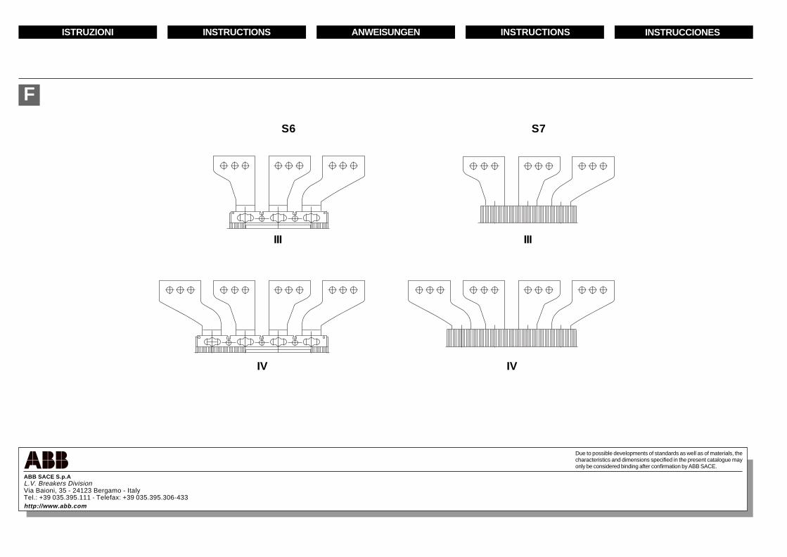
F
S6 S7
III III
IV IV
ABB SACE S.p.AL.V. Breakers DivisionVia Baioni, 35 - 24123 Bergamo - ItalyTel.: +39 035.395.111 - Telefax: +39 035.395.306-433http://www.abb.com
Due to possible developments of standards as well as of materials, thecharacteristics and dimensions specified in the present catalogue mayonly be considered binding after confirmation by ABB SACE.