Embed Size (px)
Citation preview
Amar-Drainer-BoxOriginalbetriebsanleitung2331.811/3-90
Automatische Schmutzwasser-Hebeanlagefür Unter-/Überfluraufstellung
Automatic Waste Water Lifting Unit for Underfloor/Above-floor InstallationAutomatic
Poste de relevage automatique pour eaux uséespour installation sur sol ou enterrée
Automatische vuilwateropvoerinstallatievoor onder- en bovenvloeropstelling
OriginalbetriebsanleitungDiese Betriebsanleitung enthält wichtige Hin-weise und Warnvermerke. Bitte vor Einbau,elektrischemAnschluß und Inbetriebnahme un-bedingt lesen.Weitere Betriebsanleitungen, dieKomponenten dieses Aggregates betreffen,sind zusätzlich zu berücksichtigen.DieseBetriebsanleitung soll in der Nähe der An-lage aufbewahrt werden.
Original operating manualThese operating instructions contain funda-mental information and precautionary notes.Please read the manual thoroughly prior to in-stallation of unit, connection to the power supplyand commissioning. It is imperative to complywith all other operating instructions referring tocomponents of this unit.This manual shall always be kept close to theunit’s location of operation.
Notice de service d’origineCette notice de service contient des informa-tions et mises en garde importantes. Avant l’in-stallation, le branchement électrique et la miseen route, lire impérativement cedocument et ob-server aussi les notices éventuelles fourniesavec les composants du groupe.Conserver ce document à proximité du poste derelevage.
Originele bedrijfsvoorschriftDit bedrijfsvoorschrift bevat belangrijke aanwij-zingen en waarschuwingen. Wij vragen udringend dit bedrijfsvoorschrift voor hetinbouwen, de elektrische aansluiting en het inbedrijf nemen te lezen. Er dient bovendienrekening te worden gehouden met de overigebedrijfsvoorschriften, die betrekking hebben opde componenten van dit aggregaat.
Ama-Drainer-Box
2
InhaltsverzeichnisSeite
1 Allgemeines 3
2 Sicherheit 3
3 Transport, Zwischenlagerung 4
4 Beschreibung von Erzeugnis und Zubehör 4
5 Aufstellung/Einbau 4
6 Inbetriebnahme / Außerbetriebnahme 8
7 Wartung/Instandhaltung 9
8 Störungen/Ursachen und Beseitigung 10
9 Zugehörige Unterlagen 11
ContentsPage
1 General 18
2 Safety 18
3 Transport and Interim Storage 19
4 Description of the Product and Accessories 19
5 Installation at Site 19
6 Commissioning / Shutdown 23
7 Servicing / Maintenance 24
8 Trouble-shooting 25
9 Relevant Documentation 26
SommairePage
1 Généralités 33
2 Sécurité 33
3 Transport et stockage temporaire 34
4 Description du produit et des accessoires 34
5 Installation et montage 34
6 Mise en service / Mise hors service 38
7 Entretien 39
8 Incidents, causes et remèdes 40
9 Documentation annexe 41
INHOUDSOPGAVEPagina
1 Algemeen 48
2 Veiligheid 48
3 Transport en tussentijdse opslag 49
4 Beschrijving van het aggregaat en toebehoren 49
5 Opstelling/Inbouw 49
6 In bedrijf nemen/uit bedrijf nemen 54
7 Service/onderhoud 54
8 Storingen/oorzaken en opheffen 55
9 Bijlagen 56
Caution
Ama-Drainer-Box
18
1 GeneralThis KSB unit has been developed in accordance with state-of-the-art technology; it ismanufacturedwith utmost care and sub-ject to continuous quality control.These operating instructions are intended to facilitate familia-risation with the unit and its designated use.The manual contains important information for reliable, properand efficient operation. Compliance with the operating instruc-tions is of vital importance to ensure reliability and a long ser-vice life of the unit and to avoid any risks.These operating instructions do not take into account local re-gulations; the operator must ensure that such regulations arestrictly observed by all, including the personnel called in for in-stallation.This unit must not be operated beyond the limit values for themedium handled, capacity, speed, density, pressure, tempera-ture and motor rating specified in the technical documentation.Make sure that operation is in accordance with the instructionslaid down in this manual or in the contract documentation.The name plate indicates the type series / size, main operatingdata and works / serial number; please quote this informationin all queries, repeat orders and particularly when orderingspare parts.If you need any additional information or instructions exceedingthe scope of this manual or in case of damage please contactKSB’s nearest customer service centre.
2 SafetyThese operating instructions contain fundamental informationwhich must be complied with during installation, operation andmaintenance. Therefore this operating manual must be readand understood both by the installing personnel and the re-sponsible trained personnel / operators prior to installation andcommissioning, and it must always be kept close to the locationof operation of the machine / unit for easy access.Not only must the general safety instructions laid down in thischapter on ”Safety” be complied with, but also the safety in-structions outlined under specific headings.
2.1 Marking of Instructions in the ManualThe safety instructions contained in thismanual whose non-ob-servancemight cause hazards to persons are speciallymarkedwith the general hazard sign, namely
safety sign in accordance with ISO 7000 -- 0434.The electrical danger warning sign is
safety sign in accordance with IEC 417 -- 5036.besonders gekennzeichnet.
The word
is used to introduce safety instructions whose non-observancemay lead to damage to the machine and its functions.
Instructions attached directly to the machine, e.g.-- arrow indicating the direction of rotation-- markings for fluid connectionsmust always be complied with and be kept in a perfectly legiblecondition at all times.
2.2 Personnel Qualification and TrainingAll personnel involved in the operation, maintenance, inspectionand installation of the unit must be fully qualified to carry out thework involved. Personnel responsibilities, competence andsupervision must be clearly defined by the operator. If the per-sonnel in question is not already in possession of the requisiteknow-how, appropriate training and instruction must be pro-vided. If required, the operator may commission the manufac-turer / supplier to take care of such training. In addition, the oper-ator is responsible for ensuring that the contents of the operatinginstructions are fully understood by the responsible personnel.
2.3 Non-compliance with Safety InstructionsNon-compliance with safety instructions can jeopardize thesafety of personnel, the environment and the machine / unit it-self. Non-compliance with these safety instructions will alsolead to forfeiture of any and all rights to claims for damages.In particular, non-compliance can, for example, result in:-- failure of important unit functions,-- failure of prescribed maintenance and servicing practices,-- hazard to persons by electrical,mechanical and chemical ef-
fects,-- hazard to the environment due to leakage of hazardous sub-
stances.
2.4 Safety AwarenessIt is imperative to comply with the safety instructions containedin this manual, the relevant national health and safety regula-tions and the operator’s own internal work, operation and safetyregulations.
2.5 Safety Instructions for the Operator / User-- Any hot or cold components that could pose a hazard must
be equipped with a guard by the operator.-- Guards which are fitted to prevent accidental contact with
moving parts (e.g. coupling) must not be removed whilst theunit is operating.
-- Leakages (e.g at the shaft seal) of hazardousmedia handled(e.g. explosive, toxic, hot) must be contained so as to avoidany danger to persons and the environment. Pertinent legalprovisions must be adhered to.
-- Electrical hazards must be eliminated. (In this respect referto the relevant safety regulations applicable to differentcountries and / or the local energy supply companies.)
2.6 Safety Instructions for Maintenance,Inspection and Installation Work
The operator is responsible for ensuring that all maintenance,inspection and installation work be performed by authorised,qualified specialist personnel who are thoroughly familiar withthe manual.Work on the machine / unit must be carried out only duringstandstill. The shutdown procedure described in themanual fortaking the unit out of service must be adhered to without fail.Pumps or pump units handling media injurious to health mustbe decontaminated.
Caution
Caution
Ama-Drainer-Box
19
Immediately following completion of the work, all safety-rel-evant and protective devices must be re-installed and / or re-activated.Please observe all instructions set out in the chapter on ”Com-missioning / Start-up” before returning the unit to service.
2.7 Unauthorized Modification andManufacture of Spare Parts
Modifications or alterations of the equipment supplied are onlypermitted after consultation with the manufacturer. Originalspare parts and accessories authorised by the manufacturerensure safety. The use of other parts can invalidate any liabilityof the manufacturer for consequential damage.
2.8 Unauthorized Modes of OperationThe warranty relating to the operating reliability and safety ofthe unit supplied is only valid if the equipment is used in accord-ance with its designated use. The limits stated in the data sheetmust not be exceeded under any circumstances.
3 Transport and Interim Storage3.1 TransportSingle-lifting Unit Underfloor Box 32/40The unit is supplied in 4 individual units.-- Tank with interstage casing, provisional cover, discharge
pipe with return stop, floor drain and odour trap-- Pump with cable and shockproof plug or CEE plug-- Cover (flush or recess plate)-- Connection set
Dual Lifting Unit - Underfloor Box Z 32The dual unit is supplied ready for connection and comprisesthe following components:-- Tankwith interstage casing, provisional cover, two submers-
ible motor pumps starting and stopping automatically whichfeature an integrated swing check valve, a floor drain and anodour trap
-- Cover (flush or recess plate)-- Switchgear for dual units
Inspect the units for transport damage prior to assembly and in-stallation.
3.2 Interim StorageThe unit should be stored in a dry, dark, frost-proof room not ex-posed to sunlight.
4 Description of the Product andAccessories
4.1 Technical SpecificationKSBwaste water lifting units are designed to collect and auto-matically lift waste water without faeces above the backwashlevel.
Ama-Drainer-Box is not suitable for sewage from urinals andtoilets. For these applications please use our Ama-Lift, Ama-Sani, mini-Compacta/Compacta sewage lifting units.
Substances /waterwhichmustnot bedischargedare, a.o.:F Solid matter, fibres, tar, sand, cement, ash, coarse
paper, cardboard, debris, garbage, offal, grease or oil(DIN 1986-3).
F Waste water from sanitary installations situated abovethe backwash level (EN 12 056-1).
F Waste water containing greasy substances (DIN1986-100), e.g. greasy waste water from large-scale cater-ing establishments. For drainage of greasy water, agrease separator to DIN 4040-1 must be fitted.
4.2 DesignationExample of a complete Ama-Drainer-Box.
Ama-Drainer- Box Z 1 2
Type seriesCollecting tankZ = Dual unitCover variantCode number for Ama-Drainer (here Ama-Drainer 301.1)
4.3 Underfloor Box 32 / 40Impact-resistant plastic collecting tank of PE-LLD with submers-ible motor pump starting and stopping automatically and swingcheck valve, two suction nozzles arranged at an angle of 90o,vent nozzle and discharge nozzle.Cover with vertically adjustable interstage casing for levellingpurposes.Cover plate at customer‘s choice as flash plate or recess platefor tiled floors. Both designs include floor drains and odourtraps.
4.4 Underfloor Box Z 32Ready-to-connect dual unit with two submersible motor pumpsstarting and stopping automatically. Discharge linewithin the col-lecting tank, completely assembled with swing check valves andconnection parts.Cover with vertically adjustable interstage casing for levellingpurposes.Switchgear and float switch for automatic alternate, standbyand peak load operation.Plastic plate as tank cover with screwed cable gland for powersupply cables.
4.5 Above-floor Box 32 / 40Single-piece, impact-resistant plastic collecting tank of PE-LLDwith submersible motor pump starting and stopping automati-cally and swing check valve, two suction nozzles arranged atan angle of 90°, vent nozzle and discharge nozzle.
4.6 AccessoriesAccessories can be ordered from our sales units.F Level-adjusting piece, 200 mm, to increase the installation
depthF KSB alarm switchgears AS 0, AS 2, AS 4 and AS 5F M 1 alarm contactor for KSB alarm switchgears
5 Assembly / Installation at Site5.1 Safety RegulationsF Your electrical installation must be in accordance with
VDE 0100/IEC 364; i.e, the sockets must have earthingterminals for example.
F Connection to the power supply must be effected by atrained electrician only. The applicable VDE regulationsmust be complied with.
F The supply mains to which the unit is connected mustbeequippedwith ahighly sensitiveearth leakagecircuitbreaker <30 mA.
F Please observe the relevant DIN VDE 0100, Part 701, sti-pulations when installing the unit in bathrooms andshower facilities.
F In the case of three-phase current the external protec-tion equipment should always have three poles and aninterlocking device. This will ensure complete separ-ation from the mains and prevent the unit from runningon two phases only.
F All electrical equipment such as switch box, alarmtransmitter and socket must be installed in a dry, flood-proof location.
Caution
Caution
Caution
Caution
Ama-Drainer-Box
20
F Caution! Switch off the pump prior to each assemblyand dismantling of the pipelines or any other work onthe unit.
F If you use an extension cord, please see to it that it is ofthe same quality as the power supply cable supplied.
F Keep unauthorized persons (e.g. children) away fromthe unit.
Please observe the stipulations of EN 12 056 “Gravity drain-age systems in buildings” when installing the unit at site.
It is imperative to comply with all other operating instruc-tions referring to components of this unit.Remove transport locks, if applicable.
5.2 Checks to Be Carried out Prior to Installation
A closed concrete pan must be provided in areas withpressing ground water.All structural work required must have been prepared asillustrated in section 9.1 Installation Instructions.Make sure the installation is frost-proof.
No driving on the Ama-Drainer-Box!
5.3 Tank Above-floor Box 32 / 40(with Plastic Plate)
Place the tank on the delivered rubber buffers and secure it tothe floor by means of steel hoops to prevent it from lifting.After determining the inlet, remove the corresponding connec-tion nozzle cover by means of a saw or right-angle grinder andconnect the inlet opening to the suction line using commercialconnection elements (see section 9.1.2). Refer to section 5.4for further instructions on installing the discharge pipe.Cut off the vent nozzle cover and connect the vent pipe bymeans of commercial connection elements, laying it with aslightly rising slope.Remove the tank cover (plastic plate) and install the submersi-ble motor pump in acc. with 5.5 or 5.7. The submersible motorpumps with a.c. motors are equipped with shock-proof plugs;the variants with three-phase motors feature CEE plugs. Priorto introducing the cable into the cable duct, the relevant plugmust be removed. In the case of three-phasemotors, the cableof the float switch must also be inserted into the cable duct.Connection of a new shock-proof plug or CEE plug must be ef-fected by an electrician only (see section 5.9).
5.4 Tank Underfloor Box 32, Z 32, 40(with Provisional Cover)
Place the complete tank 591 with interstage casing 113 on anunderlayer of gravel and backfill as illustrated in section 9.1.1Unfinished State.After determining the inlet, remove the corresponding connec-tion nozzle cover by means of a saw or right-angle grinder andconnect the inlet opening to the suction line using commercialconnection elements, e.g. parts without sockets (see section9.1.2)
Discharge line for Ama-Drainer-Box 32, Z 32(see sections 9.4 and 9.5)Connect the DN 32 discharge line (outside pipe diam. 40) usingflexible tube 719 and hose clip 733and lay it with a slightly risingslope.
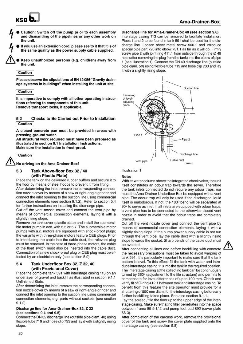
Discharge line for Ama-Drainer-Box 40 (see section 9.6)Interstage casing 113 can be removed to facilitate installation.Pipes 1 and 2 to be found in tank 591 shall be used for the dis-charge line. Loosen sheet metal screw 900.1 and introducespecial pipe part 720 into elbow 731.1 as far as it will go. Firmlyscrew pipe 2 with joint ring 411.1 from outside through the Ø 49hole (after removing the plug from the tank) into the elbow of pipe1 (see Illustration 1). Connect the DN 40 discharge line (outsidepipe diam. 50) using flexible tube 719 and hose clip 733 and layit with a slightly rising slope.
Fasteningof level-adjustingpiece
Pipe 1
Vent pipe
Suction line
Pipe 2
Discharge line
Cable duct
Illustration 1
Note:With itswater columnabove the integrated check valve, the unititself constitutes an odour trap towards the sewer. Thereforethe tank inlets connected do not require any odour traps, normust the Ama-Drainer Underfloor Box be equipped with a ventpipe. The odour trap will only be used if the discharged liquiditself is malodorous. If not, the 180o bend will be separated at90o to serve as inlet. If all inlets are equipped with odour traps,a vent pipe has to be connected to the otherwise closed ventnozzle in order to avoid that the odour traps are completelydrained.Cut off the vent nozzle cover and connect the vent pipe bymeans of commercial connection elements, laying it with aslightly rising slope. If the pump power supply cable is not runthrough the vent pipe, lay the cable duct with a slightly risingslope towards the socket. Sharp bends of the cable duct mustbe avoided.After connecting all lines and before backfilling with concretethe necessary precautions must be taken to avoid warping oftank 591. It is particularly important to make sure that the tankbottom is level. To this effect, fill the tank with water and intro-duce interstage casing 113 into the tank in the required position.The interstage casing at the collecting tank can be continuouslyturned by 360o (adjustment to the tile structure) and permits tocompensate for level differences of up to 100 mm. Check andverify fit of O-ring 412.1 between tank and interstage casing. Tobenefit from this feature the site operator must provide for ashuttering of 550mmdiam. for the interstage casing before anyfurther backfilling takes place. See also section 9.1.1.Lay the screed / tile the floor up to the upper edge of the inter-stage casing. Make sure that no filler penetrates into the spacebetween frame 89-9.1/.2 and pump foot pad 892 (cover plate68-3).After completion of the carcass work, remove the provisionalcover of the tank and screw the cover plate supplied onto theinterstage casing (see section 5.8).
Ama-Drainer-Box
21
5.5 Submersible Motor Pump forAma-Drainer-Box 32 with Installation Kit
For variants, see sections 5.4.1 to 5.4.3 (see illustration in sec-tion 9.4).Separate the discharge line installed in tank 591 between deliv-ery suspension pipes 713.1 and 713.2 by loosening screw900.6. Screw delivery suspension pipe 713.1 including returnstop 854 into joining pipe 71-14 of pump 81-53. Loosen unionnut 920.3. Place pump 81-53 with discharge line into the tank.Slide delivery suspension pipe 713.1 into 713.2 and securethem both using screw 900.6. Level up, if required, by turningpipe union 731.Now turn pump 81-53 to the left until it almost touches the tankwall (thus permitting freemovement of the float arm) and firmlytighten union nut 920.3.Once the union nut has been firmly tightened it must be imposs-ible to move the pump any further. If the pump can still bemoved, the pump discharge nozzle and pipe union 731 have tobe sealed by means of suitable sealing material (e.g. teflontape).The submersiblemotor pumps are equippedwith a shock-proofplug.Prior to introducing the cable into the cable duct, the relevantplug must be removed. Connection of a new shockproof plugmust be effected by a trained electrician only (see also section5.8).A free cable length of approx. 1 m should always remain in thetank to permit lifting the pump out of the tank for servicing.Please make sure that the cable will not get caught at the floatarm.
5.5.1 Ama-Drainer-Box 32 with Ama-Drainer 324 SE(see illustration in section 9.4)
On Underfloor Box with Ama-Drainer 324 SE, remove socket73-1 with swing check valve.
Illustration 2 Ama-Drainer 324 SE
Take joining pipe 71-14 (70 mm long) from the installation kitand screw it onto the pump discharge nozzle as far as it will go.Separate the lower threaded part of the discharge line, whichhas been dismantled as described in section 5.4, at pipe union731 (above the octagon, see Illustration 3). Screw union nut920.3 and pipe union into joining pipe.
713.1
920.3
731
separate here
Illustration 3
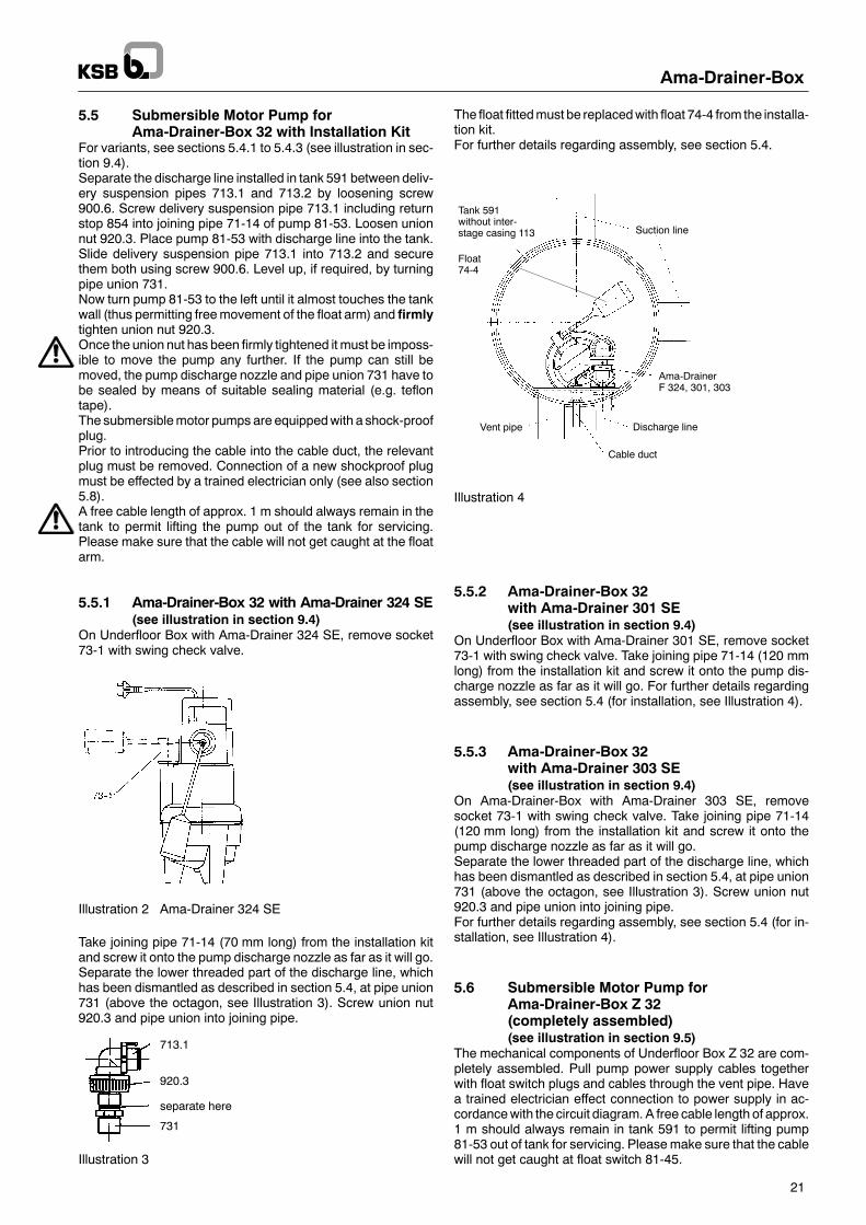
The float fittedmust be replacedwith float 74-4 from the installa-tion kit.For further details regarding assembly, see section 5.4.
Tank 591without inter-stage casing 113 Suction line
Ama-DrainerF 324, 301, 303
Discharge line
Cable duct
Vent pipe
Float74-4
Illustration 4
5.5.2 Ama-Drainer-Box 32with Ama-Drainer 301 SE(see illustration in section 9.4)
On Underfloor Box with Ama-Drainer 301 SE, remove socket73-1 with swing check valve. Take joining pipe 71-14 (120 mmlong) from the installation kit and screw it onto the pump dis-charge nozzle as far as it will go. For further details regardingassembly, see section 5.4 (for installation, see Illustration 4).
5.5.3 Ama-Drainer-Box 32with Ama-Drainer 303 SE(see illustration in section 9.4)
On Ama-Drainer-Box with Ama-Drainer 303 SE, removesocket 73-1 with swing check valve. Take joining pipe 71-14(120 mm long) from the installation kit and screw it onto thepump discharge nozzle as far as it will go.Separate the lower threaded part of the discharge line, whichhas been dismantled as described in section 5.4, at pipe union731 (above the octagon, see Illustration 3). Screw union nut920.3 and pipe union into joining pipe.For further details regarding assembly, see section 5.4 (for in-stallation, see Illustration 4).
5.6 Submersible Motor Pump forAma-Drainer-Box Z 32(completely assembled)(see illustration in section 9.5)
The mechanical components of Underfloor Box Z 32 are com-pletely assembled. Pull pump power supply cables togetherwith float switch plugs and cables through the vent pipe. Havea trained electrician effect connection to power supply in ac-cordancewith the circuit diagram. A free cable length of approx.1 m should always remain in tank 591 to permit lifting pump81-53 out of tank for servicing. Pleasemake sure that the cablewill not get caught at float switch 81-45.
Ama-Drainer-Box
22
5.7 Submersible Motor Pump forAma-Drainer-Box 40 with Installation Kit(see illustration in section 9.6)
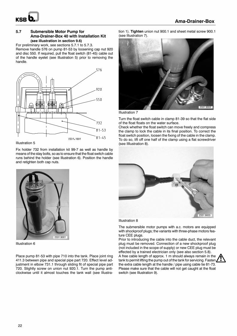
For preliminary work, see sections 5.7.1 to 5.7.3.Remove handle 576 on pump 81-53 by loosening cap nut 920and disc 550. If required, pull the float switch (81-45) cable outof the handle eyelet (see Illustration 5) prior to removing thehandle.
Illustration 5
Fix holder 732 from installation kit 99-7 as well as handle bymeansof the stay bolts, so as to ensure that the float switch cableruns behind the holder (see Illustration 6). Position the handleand retighten both cap nuts.
2331:9001
Illustration 6
Place pump 81-53 with pipe 710 into the tank. Place joint ring411.3 between pipe and special pipe part 720. Effect level ad-justment in elbow 731.1 through sliding fit of special pipe part720. Slightly screw on union nut 920.1. Turn the pump anti-clockwise until it almost touches the tank wall (see Illustra-
tion 1). Tighten union nut 900.1 and sheet metal screw 900.1(see Illustration 7).
2331:9002
Illustration 7
Turn the float switch cable in clamp 81-39 so that the flat sideof the float floats on the water surface.Check whether the float switch can move freely and compressthe clamp to lock the cable in its final position. To correct thefloat switch position, loosen the fixing of the cable in the clamp.To do so, lift off one half of the clamp using a flat screwdriver(see Illlustration 8).
2331:9003
Illustration 8
The submersible motor pumps with a.c. motors are equippedwith shockproof plugs; the variants with three-phasemotors fea-ture CEE plugs.Prior to introducing the cable into the cable duct, the relevantplug must be removed. Connection of a new shockproof plug(not included in the scope of supply) or new CEE plug must beeffected by a trained electrician only (see also section 5.8).A free cable length of approx. 1 m should always remain in thetank to permit lifting the pumpout of the tank for servicing. Fastenthe extra cable length at the handle / pipe using cable tie 81-73.Please make sure that the cable will not get caught at the floatswitch (see Illustration 9).
Ama-Drainer-Box
23
2331:9004
Illustration 9
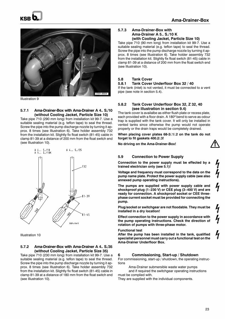
5.7.1 Ama-Drainer-Box with Ama-Drainer A 4.. S./10(without Cooling Jacket, Particle Size 10)
Take pipe 710 (290 mm long) from installation kit 99-7. Use asuitable sealing material (e.g. teflon tape) to seal the thread.Screw the pipe into the pump discharge nozzle by turning it ap-prox. 8 times (see Illustration 6). Take holder assembly 732from the installation kit. Slightly fix float switch (81-45) cable inclamp 81-39 at a distance of 200 mm from the float switch end(see Illustration 10).
Illustration 10
5.7.2 Ama-Drainer-Box with Ama-Drainer A 4.. S./35(without Cooling Jacket, Particle Size 35)
Take pipe 710 (230 mm long) from installation kit 99-7. Use asuitable sealing material (e.g. teflon tape) to seal the thread.Screw the pipe into the pump discharge nozzle by turning it ap-prox. 8 times (see Illustration 6). Take holder assembly 732from the installation kit. Slightly fix float switch (81-45) cable inclamp 81-39 at a distance of 180 mm from the float switch end(see Illustration 10).
5.7.3 Ama-Drainer-Box withAma-Drainer A 5.. S./10 K(with Cooling Jacket, Particle Size 10)
Take pipe 710 (90 mm long) from installation kit 99-7. Use asuitable sealing material (e.g. teflon tape) to seal the thread.Screw the pipe into the pump discharge nozzle by turning it ap-prox. 8 times (see Illustration 6). Take holder assembly 732from the installation kit. Slightly fix float switch (81-45) cable inclamp 81-39 at a distance of 200 mm from the float switch end(see Illustration 10).
5.8 Tank Cover5.8.1 Tank Cover Underfloor Box 32 / 40If the tank (inlet) is not vented, it must be connected to a ventpipe (see note in section 5.4).
5.8.2 Tank Cover Underfloor Box 32, Z 32, 40(see illustration in section 9.4)
The tank cover is availalbe as either flush plate or recess plate,each provided with a floor drain. A 180o bend to serve as odourtrap is supplied with the tank cover. It will only be installed invented tanks since otherwise the pump would not operateproperly or the drain traps would be completely drained.
When placing cover plates 68-3/.1/.2 on the tank do notforget to fit gaskets 400.2/.3!
No driving on the Ama-Drainer-Box!
5.9 Connection to Power Supply
Connection to the power supply must be effected by atrained electrician only (see 5.1)!
Voltage and frequency must correspond to the data on thepump name plate. Protect the power supply cable (see alsoannexed pump operating instructions).
The pumps are supplied with power supply cable andshockproof plug (1~230 V) or CEE plug (3~400 V) and areready for connection. A shockproof socket or CEE three-phase current socket must be provided for connecting thepump.
Plug/socket or switchgear are not floodable. Theymust beinstalled in a dry location!
Effect connection to the power supply in accordance withthe pump operating instructions. Check the direction ofrotation of pumps with three-phase motor.
Functional testAfter the pump has been installed in the tank, qualifiedspecialist personnelmust carry out a functional test on theAma-Drainer Underfloor Box.
6 Commissioning, Start-up / ShutdownFor commissioning, start-up / shutdown, the operating instruc-tions
Ama-Drainer submersible waste water pumpsand if required the switchgear operating instructions
must be complied with.They are supplied with the individual components.
Ama-Drainer-Box
24
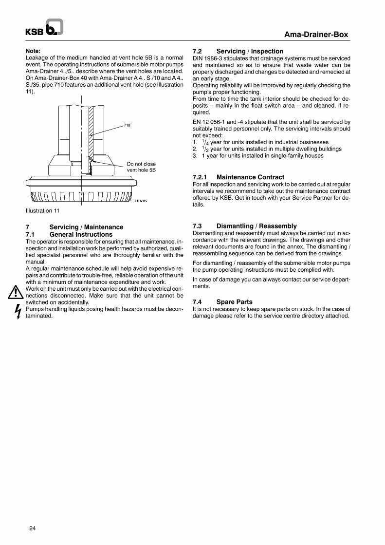
Note:Leakage of the medium handled at vent hole 5B is a normalevent. The operating instructions of submersible motor pumpsAma-Drainer 4../5.. describe where the vent holes are located.On Ama-Drainer-Box 40 with Ama-Drainer A 4.. S./10 and A 4..S./35, pipe 710 features an additional vent hole (see Illustration11).
Do not closevent hole 5B
Illustration 11
7 Servicing / Maintenance7.1 General InstructionsThe operator is responsible for ensuring that all maintenance, in-spection and installationwork be performed by authorized, quali-fied specialist personnel who are thoroughly familiar with themanual.A regular maintenance schedule will help avoid expensive re-pairs and contribute to trouble-free, reliable operationof theunitwith a minimum of maintenance expenditure and work.Work on the unit must only be carried out with the electrical con-nections disconnected. Make sure that the unit cannot beswitched on accidentally.Pumps handling liquids posing health hazards must be decon-taminated.
7.2 Servicing / InspectionDIN 1986-3 stipulates that drainage systems must be servicedand maintained so as to ensure that waste water can beproperly discharged and changes be detected and remedied atan early stage.Operating reliability will be improved by regularly checking thepump’s proper functioning.From time to time the tank interior should be checked for de-posits – mainly in the float switch area – and cleaned, if re-quired.
EN 12 056-1 and -4 stipulate that the unit shall be serviced bysuitably trained personnel only. The servicing intervals shouldnot exceed:1. 1/4 year for units installed in industrial businesses2. 1/2 year for units installed in multiple dwelling buildings3. 1 year for units installed in single-family houses
7.2.1 Maintenance ContractFor all inspection and servicing work to be carried out at regularintervals we recommend to take out the maintenance contractoffered by KSB. Get in touch with your Service Partner for de-tails.
7.3 Dismantling / ReassemblyDismantling and reassembly must always be carried out in ac-cordance with the relevant drawings. The drawings and otherrelevant documents are found in the annex. The dismantling /reassembling sequence can be derived from the drawings.
For dismantling / reassembly of the submersible motor pumpsthe pump operating instructions must be complied with.
In case of damage you can always contact our service depart-ments.
7.4 Spare PartsIt is not necessary to keep spare parts on stock. In the case ofdamage please refer to the service centre directory attached.
Pum
pisrunning,butdoesnotdeliver
Pum
pdeliversinsufficientflowrate
Excessive
current/pow
erinput
Insufficientdischarge
head
Vibrations
andnoiseduringpumpoperation
Key
Ama-Drainer-Box
25
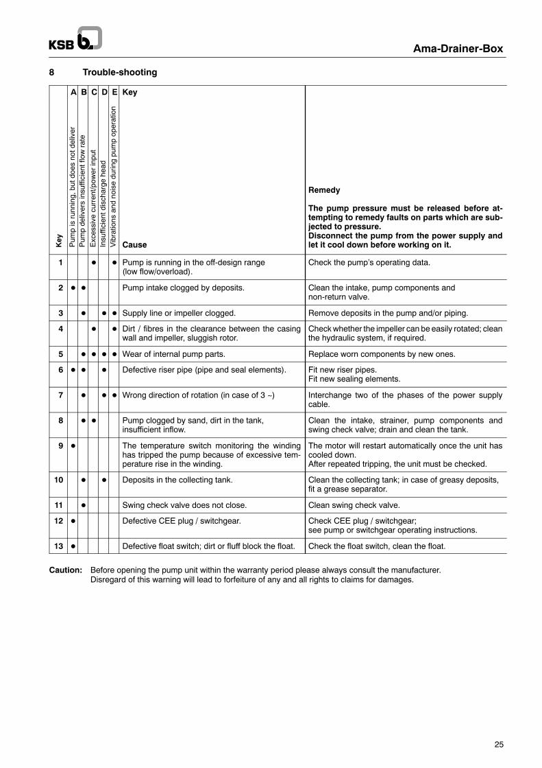
8 Trouble-shooting
A B C D E Key
Cause
Remedy
The pump pressure must be released before at-tempting to remedy faults on parts which are sub-jected to pressure.Disconnect the pump from the power supply andlet it cool down before working on it.
1 D D Pump is running in the off-design range(low flow/overload).
Check the pump’s operating data.
2 D D Pump intake clogged by deposits. Clean the intake, pump components andnon-return valve.
3 D D D Supply line or impeller clogged. Remove deposits in the pump and/or piping.
4 D D Dirt / fibres in the clearance between the casingwall and impeller, sluggish rotor.
Checkwhether the impeller can be easily rotated; cleanthe hydraulic system, if required.
5 D D D D Wear of internal pump parts. Replace worn components by new ones.
6 D D D Defective riser pipe (pipe and seal elements). Fit new riser pipes.Fit new sealing elements.
7 D D D Wrong direction of rotation (in case of 3 ~) Interchange two of the phases of the power supplycable.
8 D D Pump clogged by sand, dirt in the tank,insufficient inflow.
Clean the intake, strainer, pump components andswing check valve; drain and clean the tank.
9 D The temperature switch monitoring the windinghas tripped the pump because of excessive tem-perature rise in the winding.
The motor will restart automatically once the unit hascooled down.After repeated tripping, the unit must be checked.
10 D D Deposits in the collecting tank. Clean the collecting tank; in case of greasy deposits,fit a grease separator.
11 D Swing check valve does not close. Clean swing check valve.
12 D Defective CEE plug / switchgear. Check CEE plug / switchgear;see pump or switchgear operating instructions.
13 D Defective float switch; dirt or fluff block the float. Check the float switch, clean the float.
Caution: Before opening the pump unit within the warranty period please always consult the manufacturer.Disregard of this warning will lead to forfeiture of any and all rights to claims for damages.
Ama-Drainer-Box
26
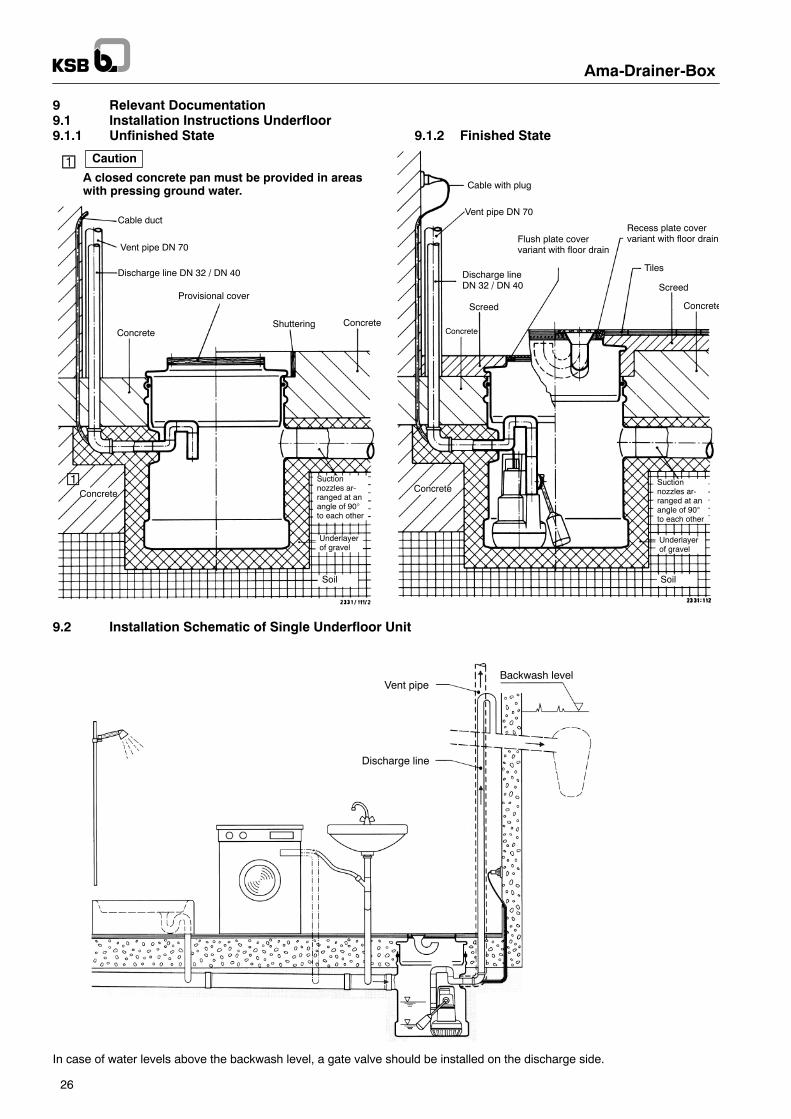
9 Relevant Documentation9.1 Installation Instructions Underfloor9.1.1 Unfinished State 9.1.2 Finished State
Discharge line DN 32 / DN 40
Cable duct
Vent pipe DN 70
ConcreteConcrete
Concrete
Shuttering
Underlayerof gravel
Underlayerof gravel
Soil Soil
Screed
Screed
Cable with plug
Vent pipe DN 70
Tiles
Concrete
Flush plate covervariant with floor drain
Recess plate covervariant with floor drain
Discharge lineDN 32 / DN 40
Concrete
Suctionnozzles ar-ranged at anangle of 90°to each other
Suctionnozzles ar-ranged at anangle of 90°to each other
Concrete
Provisional cover
Caution¡A closed concrete pan must be provided in areaswith pressing ground water.
¡
9.2 Installation Schematic of Single Underfloor Unit
Vent pipeBackwash level
Discharge line
In case of water levels above the backwash level, a gate valve should be installed on the discharge side.
Ama-Drainer-Box
27
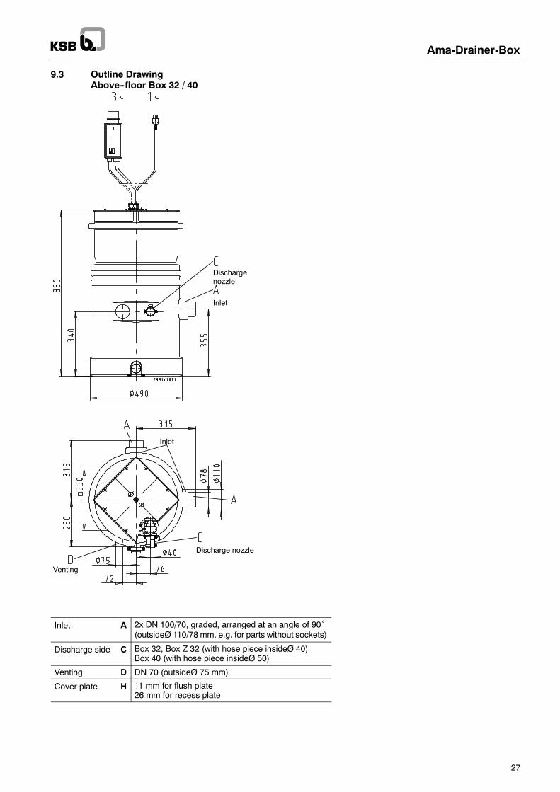
9.3 Outline DrawingAbove--floor Box 32 / 40
Inlet
Dischargenozzle
Venting
Discharge nozzle
Inlet
Inlet A 2x DN 100/70, graded, arranged at an angle of 90˚(outsideØ 110/78 mm, e.g. for parts without sockets)
Discharge side C Box 32, Box Z 32 (with hose piece insideØ 40)Box 40 (with hose piece insideØ 50)
Venting D DN 70 (outsideØ 75 mm)
Cover plate H 11 mm for flush plate26 mm for recess plate
Ama-Drainer-Box
28
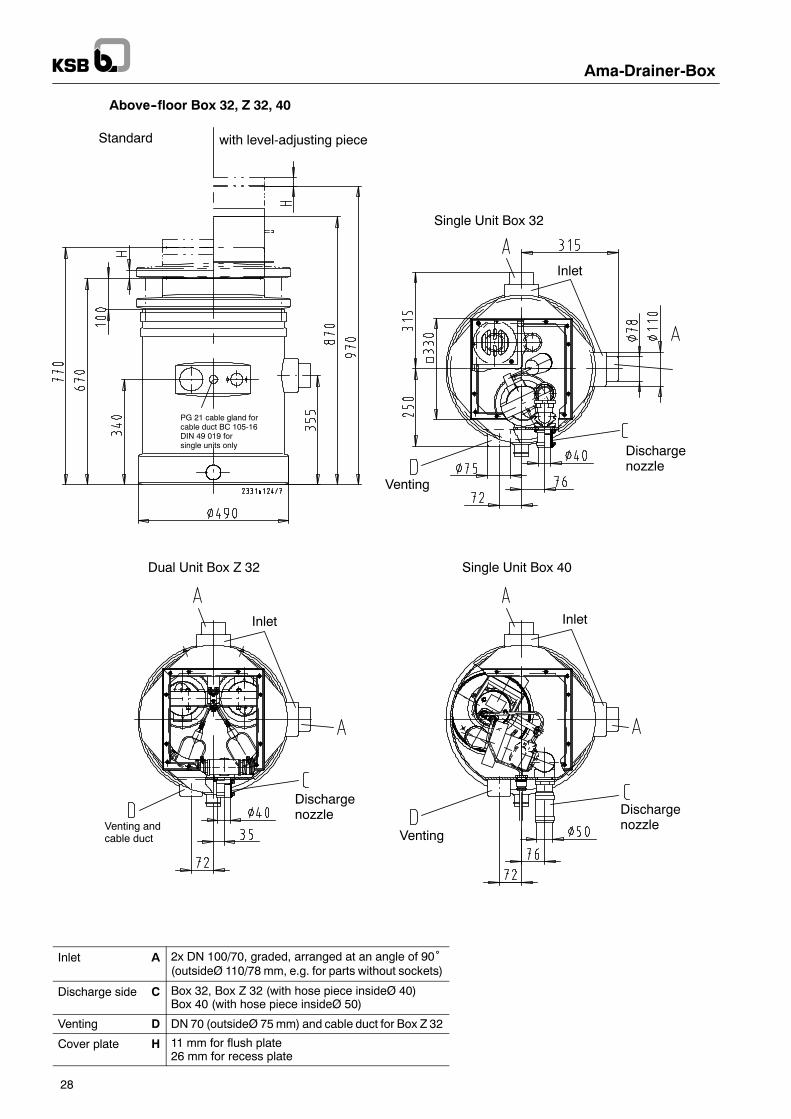
Above--floor Box 32, Z 32, 40
Standard with level-adjusting piece
Single Unit Box 32
Inlet
Dischargenozzle
Venting
Single Unit Box 40Dual Unit Box Z 32
Dischargenozzle Discharge
nozzleVenting
Venting andcable duct
InletInlet
PG 21 cable gland forcable duct BC 105-16DIN 49 019 forsingle units only
Inlet A 2x DN 100/70, graded, arranged at an angle of 90˚(outsideØ 110/78 mm, e.g. for parts without sockets)
Discharge side C Box 32, Box Z 32 (with hose piece insideØ 40)Box 40 (with hose piece insideØ 50)
Venting D DN 70 (outsideØ 75mm) and cable duct for Box Z 32
Cover plate H 11 mm for flush plate26 mm for recess plate
Ama-Drainer-Box
29
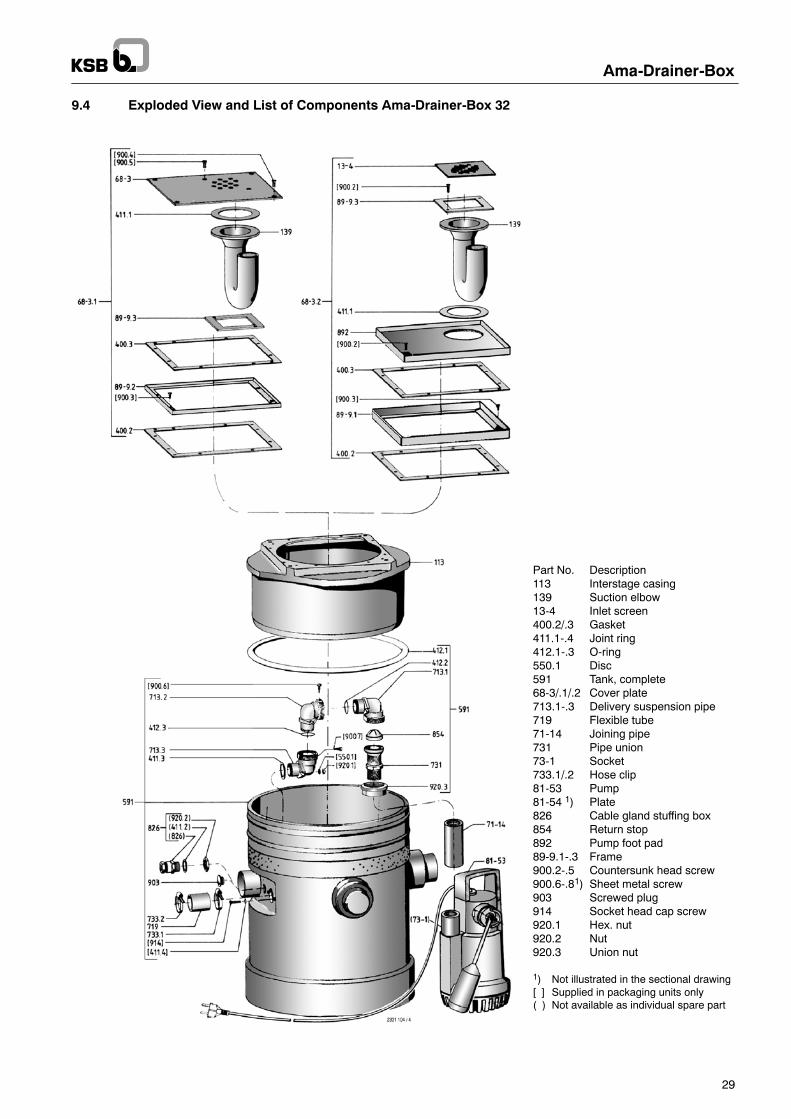
9.4 Exploded View and List of Components Ama-Drainer-Box 32
Part No. Description113 Interstage casing139 Suction elbow13-4 Inlet screen400.2/.3 Gasket411.1-.4 Joint ring412.1-.3 O-ring550.1 Disc591 Tank, complete68-3/.1/.2 Cover plate713.1-.3 Delivery suspension pipe719 Flexible tube71-14 Joining pipe731 Pipe union73-1 Socket733.1/.2 Hose clip81-53 Pump81-54 1) Plate826 Cable gland stuffing box854 Return stop892 Pump foot pad89-9.1-.3 Frame900.2-.5 Countersunk head screw900.6-.81) Sheet metal screw903 Screwed plug914 Socket head cap screw920.1 Hex. nut920.2 Nut920.3 Union nut
1) Not illustrated in the sectional drawing[ ] Supplied in packaging units only( ) Not available as individual spare part
99-6
914
[411.4]
Ama-Drainer-Box
30
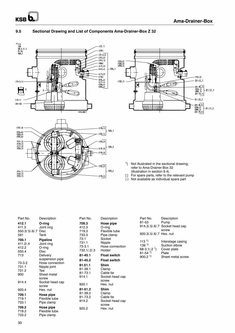
9.5 Sectional Drawing and List of Components Ama-Drainer-Box Z 32
Part No. Description
412.1 O-ring411.3 Joint ring550.3/.5/.6/.7 Disc591 Tank
700.1 Pipeline411.2/.4 Joint ring412.2 O-ring550.4 Disc713 Delivery
suspension pipe73-3.2 Hose connection731.1 Nipple joint731.2 Tee900 Sheet metal
screw914.4 Socket head cap
screw920.4 Hex. nut
709.1 Hose pipe719.1 Flexible tube733.1 Pipe clamp
709.2 Hose pipe719.2 Flexible tube733.2 Pipe clamp
Part No. Description
709.3 Hose pipe412.3 O-ring719.3 Flexible tube733.3 Pipe clamp73-1 Socket731.1 Nipple73-3.1 Hose connection732.1/.2/.3 Holder
81-45.1 Float switch81-45.2 Float switch81.51.1 Shim81-39.1 Clamp81-73.1 Cable tie914.1 Socket head cap
screw920.1 Hex. nut
81-51.2 Shim81-39.2 Clamp81-73.2 Cable tie914.2 Socket head cap
screw920.2 Hex. nut
Part No. Description81-53 Pump914.3/.5/.6/.7 Socket head cap
screw920.3/.5/.6/.7 Hex. nut
113 1) Interstage casing139 1) Suction elbow68-3.1/.2 1) Cover plate81-54 1) Plate900.2 1) Sheet metal screw
1) Not illustrated in the sectional drawing;refer to Ama-Drainer-Box 32(illustration in section 9.4).
[ ] For spare parts, refer to the relevant pump( ) Not available as individual spare part
Ama-Drainer-Box
31
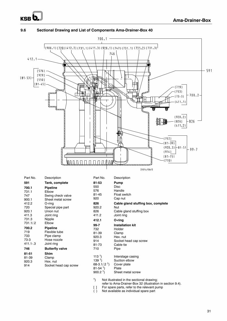
9.6 Sectional Drawing and List of Components Ama-Drainer-Box 40
Part No. Description
591 Tank, complete
700.1 Pipeline731.1 Elbow747 Swing check valve900.1 Sheet metal screw412.2 O-ring720 Special pipe part920.1 Union nut411.3 Joint ring731.3 Nipple731.1/.2 Elbow
700.2 Pipeline719 Flexible tube733 Pipe clamp73-3 Hose nozzle411.1-.3 Joint ring
746 Butterfly valve
81-51 Shim81-39 Clamp920.3 Hex. nut914 Socket head cap screw
Part No. Description
81-53 Pump550 Disc576 Handle81-45 Float switch920 Cap nut
826 Cable gland stuffing box, complete920.2 Nut826 Cable gland stuffing box411.2 Joint ring
412.1 O-ring
99-7 Installation kit732 Holder81-39 Clamp920.3 Hex. nut914 Socket head cap screw81-73 Cable tie710 Pipe
113 1) Interstage casing139 1) Suction elbow68-3.1/.2 1) Cover plate81-54 1) Plate900.2 1) Sheet metal screw
1) Not illustrated in the sectional drawing;refer to Ama-Drainer-Box 32 (illustration in section 9.4).
[ ] For spare parts, refer to the relevant pump( ) Not available as individual spare part
Ama-Drainer-Box
32
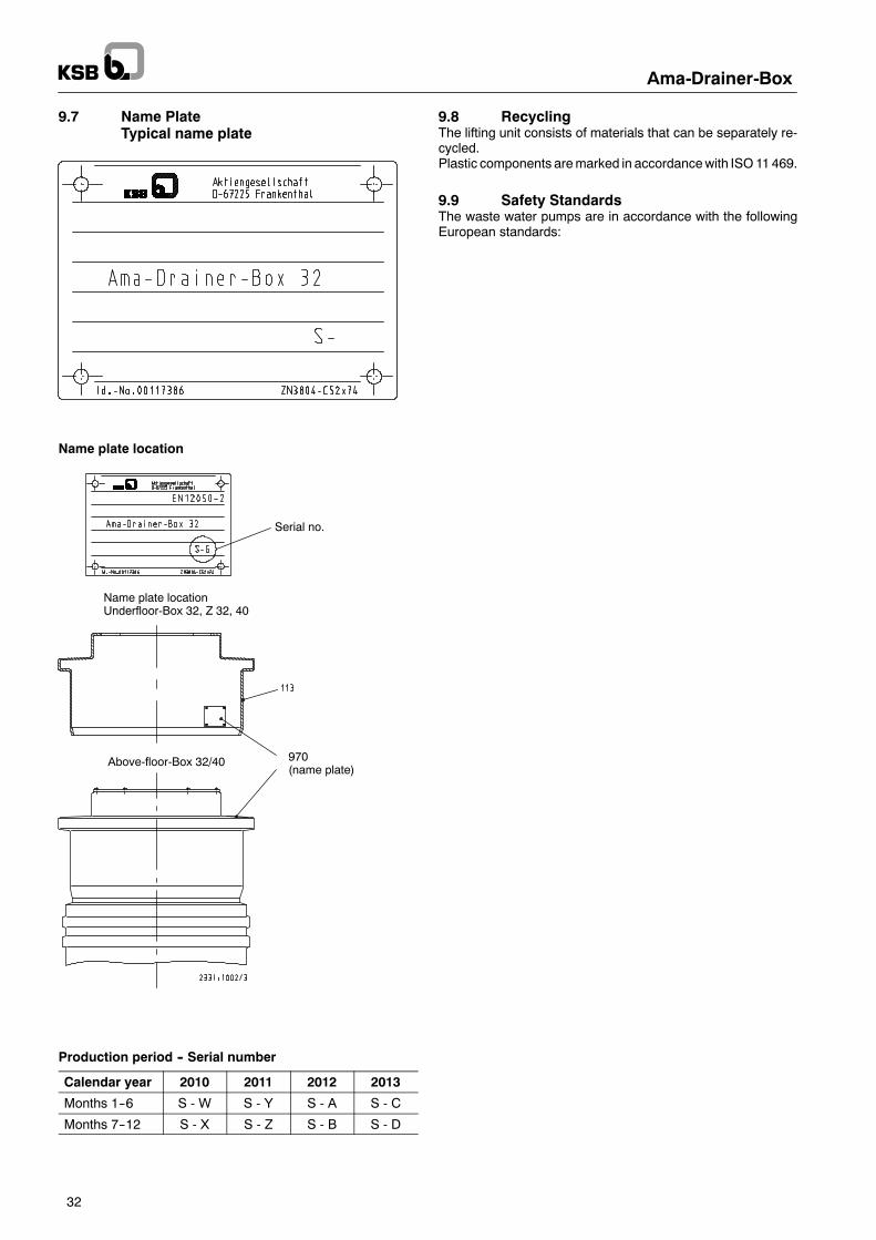
9.7 Name PlateTypical name plate
Name plate location
Serial no.
Name plate locationUnderfloor-Box 32, Z 32, 40
Above-floor-Box 32/40 970(name plate)
Production period -- Serial number
Calendar year 2010 2011 2012 2013
Months 1--6 S - W S - Y S - A S - C
Months 7--12 S - X S - Z S - B S - D
9.8 RecyclingThe lifting unit consists of materials that can be separately re-cycled.Plastic components aremarked in accordancewith ISO11469.
9.9 Safety StandardsThe waste water pumps are in accordance with the followingEuropean standards:

Technische
Änderungenbleibenvorbehalten.
2331.811/3-90
1.5.2010
01066764
Ama-Drainer-Box


![Baureihenheft Ama-Drainer r N 301/302/303 · 2016-06-23 · Ama-DrainerR N 301/302/303 2 Ama-DrainerR N 301, 302, 303 n = 3500 1/min H [m] Q[m3/h] Q[l/s] 0 2 4 6 8 10 12 14 16 18](https://img.pdfslide.org/doc/110x75/5f5f74532f099d5f3219d440/baureihenheft-ama-drainer-r-n-301302303-2016-06-23-ama-drainerr-n-301302303.jpg)