Embed Size (px)
Citation preview
Art
.Nr.
3.2
10.5
5
11/
2002
66
0SU
PER
MO
TO F
AC
TOR
Y R
EPLI
CA
200
3
660
SMC
SUPE
RM
OTO
200
3A
RT.
NR
. 3.2
10.5
4
ERG
ÄN
ZUN
G Z
UR
BED
IEN
UN
GSA
NLE
ITU
NG
SUPP
LEM
ENT
TO O
WN
ERS
HA
ND
BO
OK
660
SMC
SUPE
RM
OTO
200
3A
RT.
NO
. 3.2
10.5
4
DEU
TSC
H
2
BEDIENUNGSELEMENTE
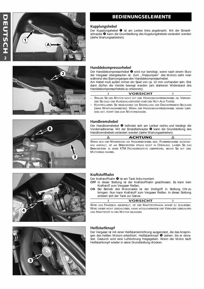
Kupplungshebel Der Kupplungshebel 1 ist am Lenker links angebracht. Mit der Einstell-schraube A kann die Grundstellung des Kupplungshebels verändert werden(siehe Wartungsarbeiten).
HanddekompressorhebelDer Handdekompressorhebel 2 wird nur benötigt, wenn nach einem Sturzder Vergaser übergelaufen ist. Zum „Freipumpen“ des Motors zieht manwährend des Startvorganges den Handdekompressorhebel.Am Hebel muß außen immer ein Spiel von ca. 10 mm vorhanden sein. Erstdann dürfen die Ventile bewegt werden (am stärkeren Widerstand desHanddekompressorhebels zu erkennen).
! VORSICHT !– STELLEN SIE DEN MOTOR NICHT MIT DEM HANDDEKOMPRESSORHEBEL AB. VERWEN-
DEN SIE DAZU DEN KURZSCHLUSSTASTER ODER DEN NOT-AUS-TASTER.– KONTROLLIEREN SIE REGELMÄSSIG DIE EINSTELLUNG DES DEKOMPRESSOR-SEILZUGES
(SIEHE WARTUNGSARBEITEN). WENN DER HANDDEKOMPRESSORHEBEL KEINEN LEER-WEG HAT, FÜHRT DIES ZUM MOTORSCHADEN.
HandbremshebelDer Handbremshebel 3 befindet sich am Lenker rechts und betätigt die Vorderradbremse. Mit der Einstellschraube B kann die Grundstellung desHandbremshebels verändert werden (siehe Wartungsarbeiten).
� ACHTUNG �WENN SICH DER WIDERSTAND AM HANDBREMSHEBEL BZW. FUSSBREMSHEBEL SCHWAM-MIG ANFÜHLT, IST AM BREMSSYSTEM ETWAS NICHT IN ORDNUNG. LASSEN SIE DASBREMSSYSTEM IN EINER KTM FACHWERKSTÄTTE ÜBERPRÜFEN, BEVOR SIE MIT DEMMOTORRAD FAHREN.
KraftstoffhahnDer Kraftstoffhahn 4 ist am Tank links montiert. OFF In dieser Stellung ist der Kraftstoffhahn geschlossen. Es kann kein
Kraftstoff zum Vergaser fließen.ON Bei Betrieb des Motorrades ist der Drehgriff in Stellung ON zu
bringen. Nun kann Kraftstoff zum Vergaser fließen. In dieser Stellungentleert sich der Tank zur Gänze.
! VORSICHT !WIRD DAS FAHRZEUG ABGESTELLT, IST DER KRAFTSTOFFHAHN IMMER ZU SCHLIESSEN.WIRD DIESER NICHT GESCHLOSSEN, KANN MÖGLICHERWEISE DER VERGASER ÜBERLAUFENUND KRAFTSTOFF IN DEN MOTOR GELANGEN.
HeißstartknopfDer Vergaser ist mit einer Heißstarteinrichtung ausgerüstet, die das Ansprin-gen des heißen Motors erleichtert. Heißstartknopf 5 ziehen, bis er einra-stet. Dadurch wird eine Luftbohrung freigegeben. Wenn der Motor läuftHeißstartknopf wieder in seine Grundstellung drücken.
1A
2
3
B
4
5
DEU
TSC
H
3
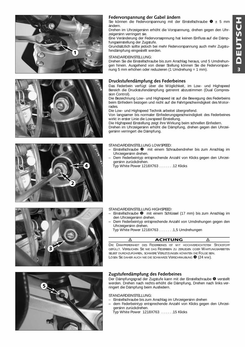
Federvorspannung der Gabel ändernSie können die Federvorspannung mit der Einstellschraube 1 ± 5 mmändern.Drehen im Uhrzeigersinn erhöht die Vorspannung, drehen gegen den Uhr-zeigersinn verringert sie.Eine Veränderung der Federvorsapnnung hat keinen Einfluss auf die Dämp-fungseinstellung der Zugstufe.Grundsätzlich sollte jedoch bei mehr Federvorspannung auch mehr Zugstu-fendämpfung eingestellt werden.
STANDARDEINSTELLUNG:Drehen Sie die Einstellschraube bis zum Anschlag heraus, und 5 Umdrehun-gen hinein. Ausgehend von dieser Stellung können Sie die Federvorspan-nung 5 mm erhöhen oder reduzieren (1 Umdrehung = 1 mm).
Druckstufendämpfung des FederbeinesDas Federbein verfügt über die Möglichkeit, im Low- und HighspeedBereich die Druckstufendämpfung getrennt abzustimmen (Dual Compres-sion Control).Die Bezeichnung Low- und Highspeed ist auf die Bewegung des Federbeinsbeim Einfedern bezogen und nicht auf die Fahrtgeschwindigkeit des Motor-rades.Die Low- und Highspeed Technik arbeitet übergreifend.Von langsamer bis normaler Einfederungsgeschwindigkeit des Federbeineswirkt in erster Linie die Lowspeed Einstellung.Die Highspeed Einstellung zeigt ihre Wirkung beim schnellen Einfedern.Drehen im Uhrzeigersinn erhöht die Dämpfung, drehen gegen den Uhrzei-gersinn verringert die Dämpfung.
STANDARDEINSTELLUNG LOWSPEED:– Einstellschraube 2 mit einem Schraubendreher bis zum Anschlag im
Uhrzeigersinn drehen. – Dem Federbeintyp entsprechende Anzahl von Klicks gegen den Uhrzei-
gersinn zurückdrehen.Typ White Power 1218X763 . . . . . . .12 Klicks
STANDARDEINSTELLUNG HIGHSPEED:– Einstellschraube 3 mit einem Schlüssel (17 mm) bis zum Anschlag im
den Uhrzeigersinn drehen.– Dem Federbeintyp entsprechende Anzahl von Umdrehungen gegen den
Uhrzeigersinn drehen.Typ White Power 1218X763 . . . . . . .1,5 Umdrehungen
� ACHTUNG �DIE DÄMPFEREINHEIT DES FEDERBEINES IST MIT HOCHVERDICHTETEM STICKSTOFFGEFÜLLT. VERSUCHEN SIE NIE DAS FEDERBEIN ZU ZERLEGEN ODER WARTUNGSARBEITENSELBST DURCHZUFÜHREN, SCHWERE VERLETZUNGEN KÖNNTEN DIE FOLGE SEIN.LÖSEN SIE DAHER AUCH NIE DIE SCHWARZE VERSCHRAUBUNG 4 (24 MM).
Zugstufendämpfung des FederbeinesDer Dämpfungsgrad der Zugstufe kann mit der Einstellschraube 5 verstelltwerden. Drehen nach rechts erhöht die Dämpfung, Drehen nach links ver-ringert die Dämpfung beim Ausfedern.
STANDARDEINSTELLUNG:– Einstellschraube bis zum Anschlag im Uhrzeigersinn drehen – dem Federbeintyp entsprechende Anzahl von Klicks gegen den Uhrzei-
gersinn zurückdrehen.Typ White Power 1218X763 . . . . . .15 Klicks
1
2
3
4
5
DEU
TSC
H
4
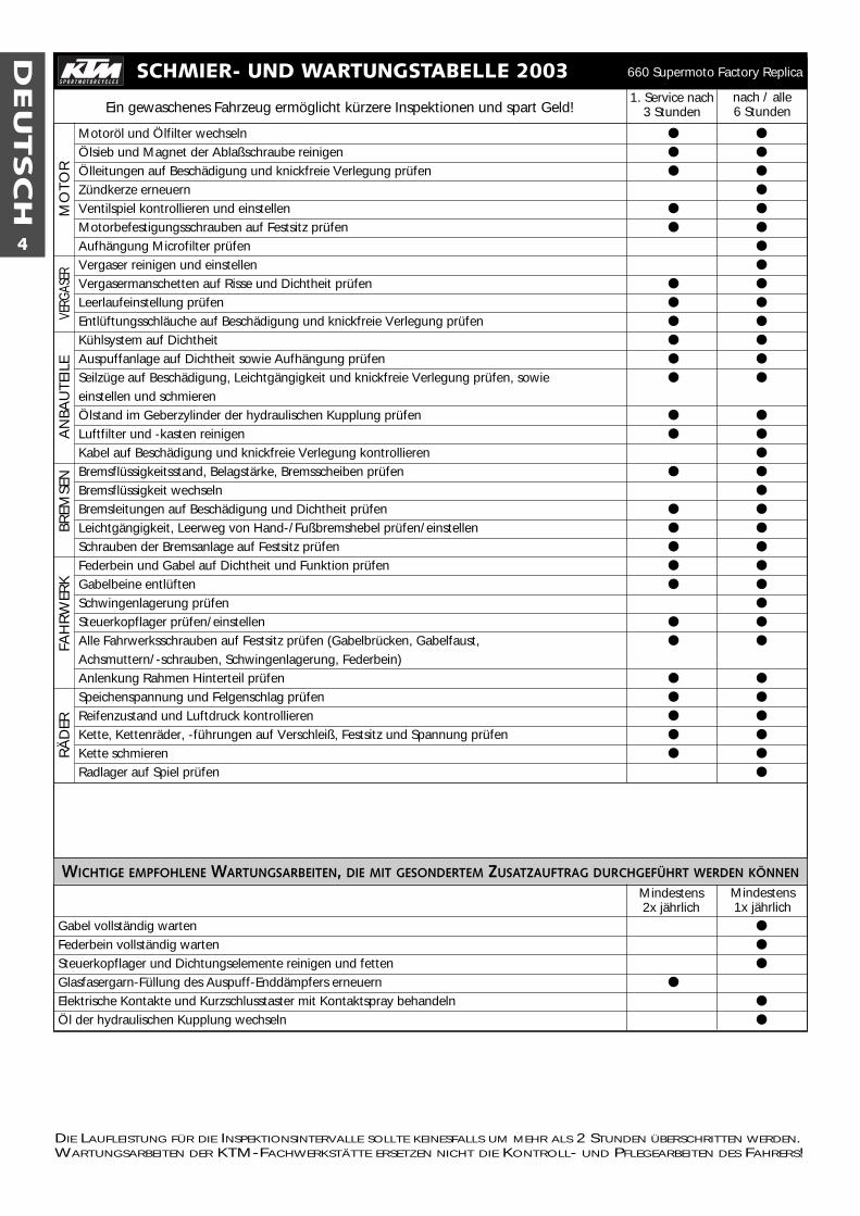
SCHMIER- UND WARTUNGSTABELLE 20031. Service nach
3 Stundennach / alle6 Stunden
DIE LAUFLEISTUNG FÜR DIE INSPEKTIONSINTERVALLE SOLLTE KEINESFALLS UM MEHR ALS 2 STUNDEN ÜBERSCHRITTEN WERDEN.WARTUNGSARBEITEN DER KTM-FACHWERKSTÄTTE ERSETZEN NICHT DIE KONTROLL- UND PFLEGEARBEITEN DES FAHRERS!
Ein gewaschenes Fahrzeug ermöglicht kürzere Inspektionen und spart Geld!
Motoröl und Ölfilter wechseln ● ●
Ölsieb und Magnet der Ablaßschraube reinigen ● ●
Ölleitungen auf Beschädigung und knickfreie Verlegung prüfen ● ●
Zündkerze erneuern ●
Ventilspiel kontrollieren und einstellen ● ●
Motorbefestigungsschrauben auf Festsitz prüfen ● ●
Aufhängung Microfilter prüfen ●
Vergaser reinigen und einstellen ●
Vergasermanschetten auf Risse und Dichtheit prüfen ● ●
Leerlaufeinstellung prüfen ● ●
Entlüftungsschläuche auf Beschädigung und knickfreie Verlegung prüfen ● ●
Kühlsystem auf Dichtheit ● ●
Auspuffanlage auf Dichtheit sowie Aufhängung prüfen ● ●
Seilzüge auf Beschädigung, Leichtgängigkeit und knickfreie Verlegung prüfen, sowie ● ●
einstellen und schmierenÖlstand im Geberzylinder der hydraulischen Kupplung prüfen ● ●
Luftfilter und -kasten reinigen ● ●
Kabel auf Beschädigung und knickfreie Verlegung kontrollieren ●
Bremsflüssigkeitsstand, Belagstärke, Bremsscheiben prüfen ● ●
Bremsflüssigkeit wechseln ●
Bremsleitungen auf Beschädigung und Dichtheit prüfen ● ●
Leichtgängigkeit, Leerweg von Hand-/Fußbremshebel prüfen/einstellen ● ●
Schrauben der Bremsanlage auf Festsitz prüfen ● ●
Federbein und Gabel auf Dichtheit und Funktion prüfen ● ●
Gabelbeine entlüften ● ●
Schwingenlagerung prüfen ●
Steuerkopflager prüfen/einstellen ● ●
Alle Fahrwerksschrauben auf Festsitz prüfen (Gabelbrücken, Gabelfaust, ● ●
Achsmuttern/-schrauben, Schwingenlagerung, Federbein)Anlenkung Rahmen Hinterteil prüfen ● ●
Speichenspannung und Felgenschlag prüfen ● ●
Reifenzustand und Luftdruck kontrollieren ● ●
Kette, Kettenräder, -führungen auf Verschleiß, Festsitz und Spannung prüfen ● ●
Kette schmieren ● ●
Radlager auf Spiel prüfen ●
WICHTIGE EMPFOHLENE WARTUNGSARBEITEN, DIE MIT GESONDERTEM ZUSATZAUFTRAG DURCHGEFÜHRT WERDEN KÖNNEN
Gabel vollständig warten ●
Federbein vollständig warten ●
Steuerkopflager und Dichtungselemente reinigen und fetten ●
Glasfasergarn-Füllung des Auspuff-Enddämpfers erneuern ●
Elektrische Kontakte und Kurzschlusstaster mit Kontaktspray behandeln ●
Öl der hydraulischen Kupplung wechseln ●
RÄ
DER
FAH
RW
ERK
BREM
SEN
AN
BAU
TEIL
EVE
RGAS
ERM
OTO
R660 Supermoto Factory Replica
Mindestens1x jährlich
Mindestens2x jährlich
DEU
TSC
H
5
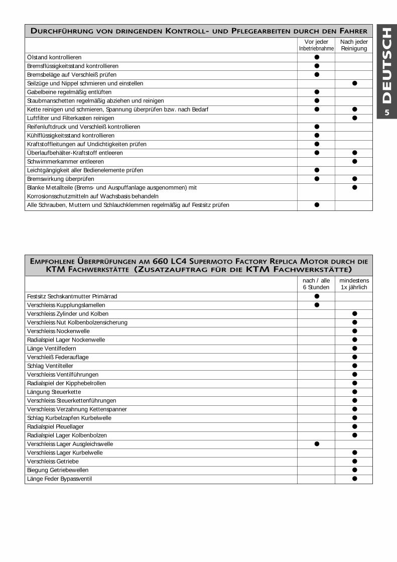
DURCHFÜHRUNG VON DRINGENDEN KONTROLL- UND PFLEGEARBEITEN DURCH DEN FAHRER
Ölstand kontrollieren ●
Bremsflüssigkeitsstand kontrollieren ●
Bremsbeläge auf Verschleiß prüfen ●
Seilzüge und Nippel schmieren und einstellen ●
Gabelbeine regelmäßig entlüften ●
Staubmanschetten regelmäßig abziehen und reinigen ●
Kette reinigen und schmieren, Spannung überprüfen bzw. nach Bedarf ● ●
Luftfilter und Filterkasten reinigen ●
Reifenluftdruck und Verschleiß kontrollieren ●
Kühlflüssigkeitsstand kontrollieren ●
Kraftstoffleitungen auf Undichtigkeiten prüfen ●
Überlaufbehälter-Kraftstoff entleeren ● ●
Schwimmerkammer entleeren ●
Leichtgängigkeit aller Bedienelemente prüfen ●
Bremswirkung überprüfen ● ●
Blanke Metallteile (Brems- und Auspuffanlage ausgenommen) mit ●
Korrosionsschutzmitteln auf Wachsbasis behandelnAlle Schrauben, Muttern und Schlauchklemmen regelmäßig auf Festsitz prüfen ●
Nach jederReinigung
Vor jederInbetriebnahme
EMPFOHLENE ÜBERPRÜFUNGEN AM 660 LC4 SUPERMOTO FACTORY REPLICA MOTOR DURCH DIEKTM FACHWERKSTÄTTE (ZUSATZAUFTRAG FÜR DIE KTM FACHWERKSTÄTTE)
Festsitz Sechskantmutter Primärrad ●
Verschleiss Kupplungslamellen ●
Verschleiss Zylinder und Kolben ●
Verschleiss Nut Kolbenbolzensicherung ●
Verschleiss Nockenwelle ●
Radialspiel Lager Nockenwelle ●
Länge Ventilfedern ●
Verschleiß Federauflage ●
Schlag Ventilteller ●
Verschleiss Ventilführungen ●
Radialspiel der Kipphebelrollen ●
Längung Steuerkette ●
Verschleiss Steuerkettenführungen ●
Verschleiss Verzahnung Kettenspanner ●
Schlag Kurbelzapfen Kurbelwelle ●
Radialspiel Pleuellager ●
Radialspiel Lager Kolbenbolzen ●
Verschleiss Lager Ausgleichswelle ●
Verschleiss Lager Kurbelwelle ●
Verschleiss Getriebe ●
Biegung Getriebewellen ●
Länge Feder Bypassventil ●
nach / alle6 Stunden
mindestens1x jährlich
DEU
TSC
H
6
WARTUNGSARBEITEN AN FAHRGESTELL UND MOTOR
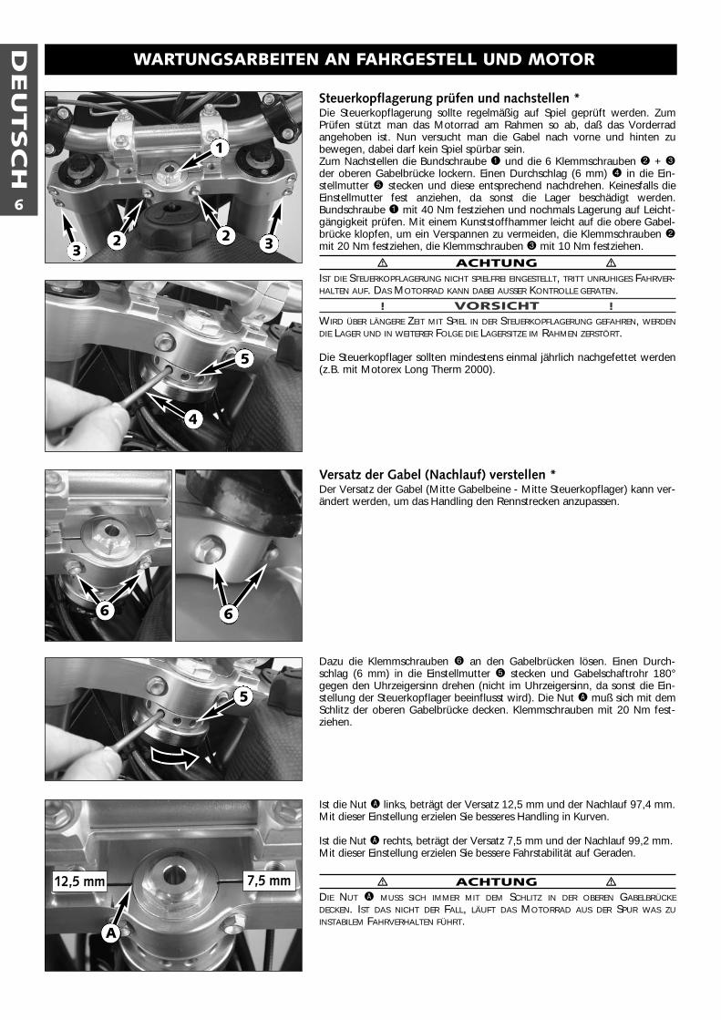
Steuerkopflagerung prüfen und nachstellen *Die Steuerkopflagerung sollte regelmäßig auf Spiel geprüft werden. ZumPrüfen stützt man das Motorrad am Rahmen so ab, daß das Vorderradangehoben ist. Nun versucht man die Gabel nach vorne und hinten zubewegen, dabei darf kein Spiel spürbar sein. Zum Nachstellen die Bundschraube 1 und die 6 Klemmschrauben 2 + 3der oberen Gabelbrücke lockern. Einen Durchschlag (6 mm) 4 in die Ein-stellmutter 5 stecken und diese entsprechend nachdrehen. Keinesfalls dieEinstellmutter fest anziehen, da sonst die Lager beschädigt werden. Bundschraube 1 mit 40 Nm festziehen und nochmals Lagerung auf Leicht-gängigkeit prüfen. Mit einem Kunststoffhammer leicht auf die obere Gabel-brücke klopfen, um ein Verspannen zu vermeiden, die Klemmschrauben 2mit 20 Nm festziehen, die Klemmschrauben 3 mit 10 Nm festziehen.
� ACHTUNG �IST DIE STEUERKOPFLAGERUNG NICHT SPIELFREI EINGESTELLT, TRITT UNRUHIGES FAHRVER-HALTEN AUF. DAS MOTORRAD KANN DABEI AUSSER KONTROLLE GERATEN.
! VORSICHT !WIRD ÜBER LÄNGERE ZEIT MIT SPIEL IN DER STEUERKOPFLAGERUNG GEFAHREN, WERDENDIE LAGER UND IN WEITERER FOLGE DIE LAGERSITZE IM RAHMEN ZERSTÖRT.
Die Steuerkopflager sollten mindestens einmal jährlich nachgefettet werden(z.B. mit Motorex Long Therm 2000).
Versatz der Gabel (Nachlauf) verstellen *Der Versatz der Gabel (Mitte Gabelbeine - Mitte Steuerkopflager) kann ver-ändert werden, um das Handling den Rennstrecken anzupassen.
Dazu die Klemmschrauben 6 an den Gabelbrücken lösen. Einen Durch-schlag (6 mm) in die Einstellmutter 5 stecken und Gabelschaftrohr 180°gegen den Uhrzeigersinn drehen (nicht im Uhrzeigersinn, da sonst die Ein-stellung der Steuerkopflager beeinflusst wird). Die Nut A muß sich mit demSchlitz der oberen Gabelbrücke decken. Klemmschrauben mit 20 Nm fest-ziehen.
Ist die Nut A links, beträgt der Versatz 12,5 mm und der Nachlauf 97,4 mm.Mit dieser Einstellung erzielen Sie besseres Handling in Kurven.
Ist die Nut A rechts, beträgt der Versatz 7,5 mm und der Nachlauf 99,2 mm.Mit dieser Einstellung erzielen Sie bessere Fahrstabilität auf Geraden.
� ACHTUNG �DIE NUT A MUSS SICH IMMER MIT DEM SCHLITZ IN DER OBEREN GABELBRÜCKEDECKEN. IST DAS NICHT DER FALL, LÄUFT DAS MOTORRAD AUS DER SPUR WAS ZUINSTABILEM FAHRVERHALTEN FÜHRT.
1
22
4
12,5 mm 7,5 mm
A
3 3
5
66
5
DEU
TSC
H
7
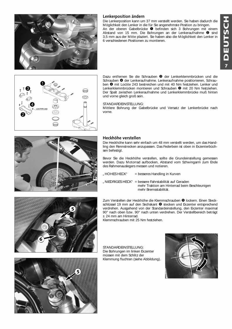
Lenkerposition ändernDie Lenkerposition kann um 37 mm verstellt werden. Sie haben dadurch dieMöglichkeit den Lenker in die für Sie angenehmste Position zu bringen. An der oberen Gabelbrücke 1 befinden sich 3 Bohrungen mit einemAbstand von 15 mm. Die Bohrungen an der Lenkeraufnahme 2 sind 3,5 mm aus der Mitte plaziert. Sie haben also die Möglichkeit den Lenker in6 verschiedenen Positionen zu montieren.
Dazu entfernen Sie die Schrauben 3 der Lenkerklemmbrücken und dieSchrauben 4 der Lenkeraufnahme. Lenkeraufnahme positionieren, Schrau-ben 4 mit Loctite 243 bestreichen und mit 40 Nm festziehen. Lenker undLenkerklemmbrücken montieren und Schrauben 3 mit 20 Nm festziehen.Der Spalt zwischen Lenkeraufnahme und Lenkerklemmbrücke muß hintenund vorne gleich groß sein.
STANDARDEINSTELLUNG:Mittlere Bohrung der Gabelbrücke und Versatz der Lenkerbrücke nachvorne.
Heckhöhe verstellenDie Heckhöhe kann sehr einfach um 48 mm verstellt werden, um das Hand-ling den Rennstrecken anzupassen. Das Federbein ist oben in Exzenterbüch-sen befestigt.
Bevor Sie die Heckhöhe verstellen, sollte die Grundeinstellung gemessenwerden. Dazu Motorrad aufbocken, Abstand vom Schwingarm zum Endedes Rahmenauslegers messen und notieren.
„HOHES HECK“ = besseres Handling in Kurven
„NIEDRIGES HECK“ = bessere Fahrstabilität auf Geradenmehr Traktion am Hinterrad beim Beschleunigen mehr Bremsstabilität.
Zum Verstellen der Heckhöhe die Klemmschrauben 5 lockern. Einen Steck-schlüssel 19 mm auf den Sechskant 6 stecken und Exzenter entsprechendverdrehen. Ausgehend von der Standardeinstellung, den Exzenter maximal90° nach oben bzw. 90° nach unten verdrehen. Der Verstellbereich beträgt± 24 mm am Hinterrad.Klemmschrauben mit 25 Nm festziehen.
STANDARDEINSTELLUNG:Die Bohrungen im linken Exzenter müssen mit dem Schlitz der Klemmung fluchten (siehe Abbildung).
LOCTITE 243
1
2
3
4
5
5
6
DEU
TSC
H
8
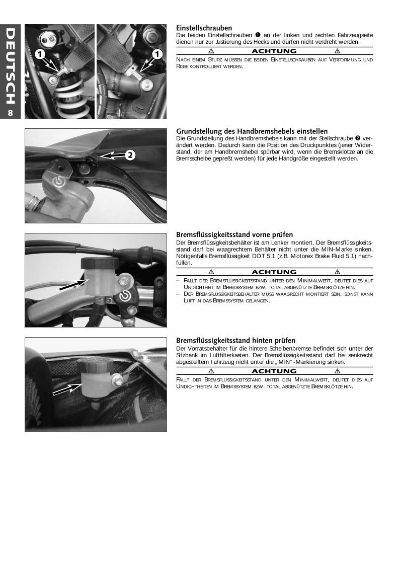
EinstellschraubenDie beiden Einstellschrauben 1 an der linken und rechten Fahrzeugseitedienen nur zur Justierung des Hecks und dürfen nicht verdreht werden.
� ACHTUNG �NACH EINEM STURZ MÜSSEN DIE BEIDEN EINSTELLSCHRAUBEN AUF VERFORMUNG UNDRISSE KONTROLLIERT WERDEN.
Grundstellung des Handbremshebels einstellenDie Grundstellung des Handbremshebels kann mit der Stellschraube 2 ver-ändert werden. Dadurch kann die Position des Druckpunktes (jener Wider-stand, der am Handbremshebel spürbar wird, wenn die Bremsklötze an dieBremsscheibe gepreßt werden) für jede Handgröße eingestellt werden.
Bremsflüssigkeitsstand vorne prüfenDer Bremsflüssigkeitsbehälter ist am Lenker montiert. Der Bremsflüssigkeits-stand darf bei waagrechtem Behälter nicht unter die MIN-Marke sinken.Nötigenfalls Bremsflüssigkeit DOT 5.1 (z.B. Motorex Brake Fluid 5.1) nach-füllen.
� ACHTUNG �– FÄLLT DER BREMSFLÜSSIGKEITSSTAND UNTER DEN MINIMALWERT, DEUTET DIES AUF
UNDICHTHEIT IM BREMSSYSTEM BZW. TOTAL ABGENÜTZTE BREMSKLÖTZE HIN.– DER BREMSFLÜSSIGKEITSBEHÄLTER MUSS WAAGRECHT MONTIERT SEIN, SONST KANN
LUFT IN DAS BREMSSYSTEM GELANGEN.
Bremsflüssigkeitsstand hinten prüfenDer Vorratsbehälter für die hintere Scheibenbremse befindet sich unter derSitzbank im Luftfilterkasten. Der Bremsflüssigkeitsstand darf bei senkrechtabgestelltem Fahrzeug nicht unter die „MlN”-Markierung sinken.
� ACHTUNG �FÄLLT DER BREMSFLÜSSIGKEITSSTAND UNTER DEN MINIMALWERT, DEUTET DIES AUFUNDICHTHEITEN IM BREMSSYSTEM BZW. TOTAL ABGENÜTZTE BREMSKLÖTZE HIN.
2
1 1
DEU
TSC
H
9
Reifen, ReifenluftdruckReifentyp, Reifenzustand und Reifenluftdruck beeinflussen das Fahrverhal-ten des Motorrades. Sie müssen vor jeder Fahrt kontrolliert werden.– Reifentyp und Reifendimension finden Sie in den Technischen Daten– Der Reifenzustand muß vor jeder Fahrt kontrolliert werden.– Der Reifenluftdruck sollte regelmäßig bei "kalten" Reifen kontrolliert
werden.
Luftdruck Vorderrad: 1,4-1,8 barLuftdruck Hinterrad: 1,4-1,7 bar
� ACHTUNG �– BESCHÄDIGTE REIFEN MÜSSEN IM INTERESSE IHRER SICHERHEIT SOFORT ERNEUERT
WERDEN.– ZU GERINGER REIFENLUFTDRUCK FÜHRT ZU ABNORMALEM VERSCHLEISS UND ZUR
ÜBERHITZUNG DES REIFENS.
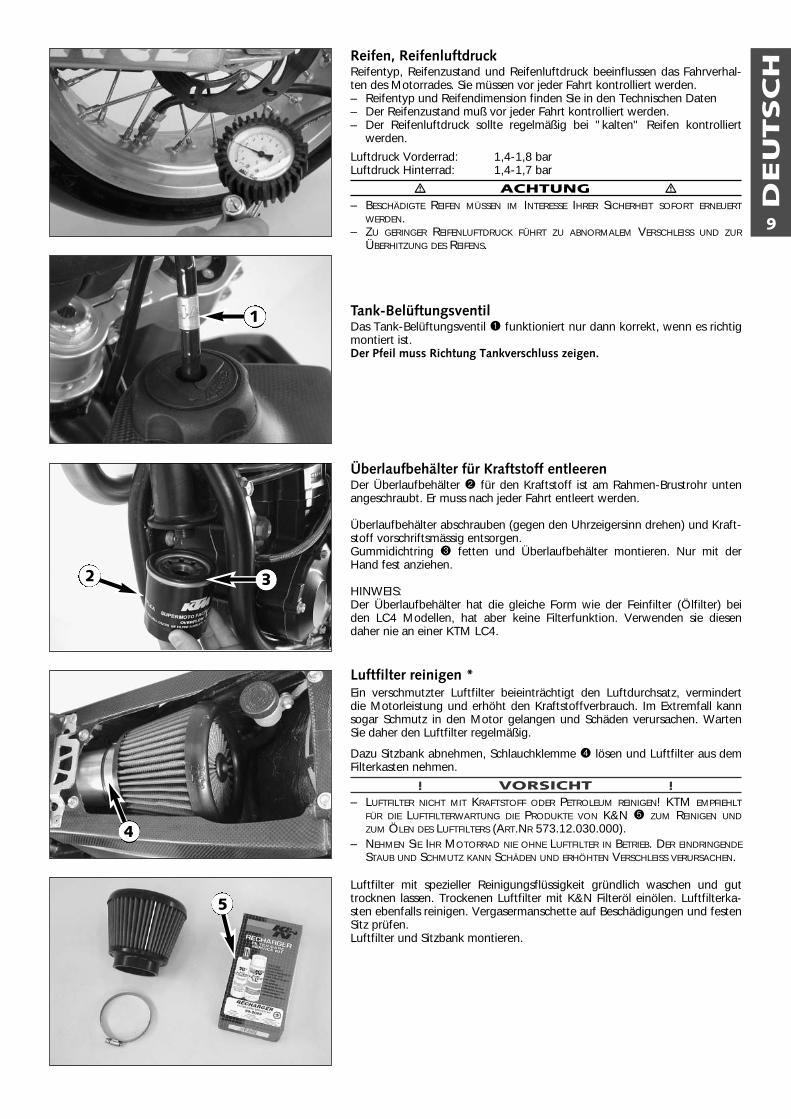
Tank-BelüftungsventilDas Tank-Belüftungsventil 1 funktioniert nur dann korrekt, wenn es richtigmontiert ist.Der Pfeil muss Richtung Tankverschluss zeigen.
Überlaufbehälter für Kraftstoff entleerenDer Überlaufbehälter 2 für den Kraftstoff ist am Rahmen-Brustrohr untenangeschraubt. Er muss nach jeder Fahrt entleert werden.
Überlaufbehälter abschrauben (gegen den Uhrzeigersinn drehen) und Kraft-stoff vorschriftsmässig entsorgen.Gummidichtring 3 fetten und Überlaufbehälter montieren. Nur mit derHand fest anziehen.
HINWEIS:Der Überlaufbehälter hat die gleiche Form wie der Feinfilter (Ölfilter) beiden LC4 Modellen, hat aber keine Filterfunktion. Verwenden sie diesendaher nie an einer KTM LC4.
Luftfilter reinigen *Ein verschmutzter Luftfilter beieinträchtigt den Luftdurchsatz, vermindertdie Motorleistung und erhöht den Kraftstoffverbrauch. Im Extremfall kannsogar Schmutz in den Motor gelangen und Schäden verursachen. WartenSie daher den Luftfilter regelmäßig.
Dazu Sitzbank abnehmen, Schlauchklemme 4 lösen und Luftfilter aus demFilterkasten nehmen.
! VORSICHT !– LUFTFILTER NICHT MIT KRAFTSTOFF ODER PETROLEUM REINIGEN! KTM EMPFIEHLT
FÜR DIE LUFTFILTERWARTUNG DIE PRODUKTE VON K&N 5 ZUM REINIGEN UNDZUM ÖLEN DES LUFTFILTERS (ART.NR 573.12.030.000).
– NEHMEN SIE IHR MOTORRAD NIE OHNE LUFTFILTER IN BETRIEB. DER EINDRINGENDESTAUB UND SCHMUTZ KANN SCHÄDEN UND ERHÖHTEN VERSCHLEISS VERURSACHEN.
Luftfilter mit spezieller Reinigungsflüssigkeit gründlich waschen und guttrocknen lassen. Trockenen Luftfilter mit K&N Filteröl einölen. Luftfilterka-sten ebenfalls reinigen. Vergasermanschette auf Beschädigungen und festenSitz prüfen.Luftfilter und Sitzbank montieren.
3
1
2
4
5
DEU
TSC
H
10
Glasfasergarnfüllung des Auspuff-Enddämpfers erneuern* Der Auspuff-Enddämpfer ist zur Schalldämpfung mit Glasfasergarn gefüllt.Durch die Hitzeeinwirkung wird das Glasfasergarn locker. Das kann zu Lei-stungsverlust führen und die Dämpfung des Schalldämpfers wird vermindert. Zum Erneuern der Glasfasergarnfüllung Auspuff-Enddämpfer demontieren.Alle 8 Nieten aufbohren und Enddämpfer zerlegen. Teile reinigen und aufRisse kontrollieren.Zur leichteren Montage der Glasfasergarn-Packung das hintere Ende desAuspuffrohres 1 mit Gewebeband umwickeln. Glasfasergarn-Packung aufdas Auspuffrohr schieben, Aussenrohr montieren und vorne mit 4 Nietenfixieren. Auspufrohr zentrieren, Endkappe und Nieten montieren.
� ACHTUNG �DIE AUSPUFFANLAGE WIRD BEIM BETRIEB DES MOTORRADES SEHR HEISS. BEGINNEN SIEMIT DEN ARBEITEN AN DER AUSPUFFANLAGE ERST NACH DEM ABKÜHLEN UM VERBREN-NUNGEN ZU VERMEIDEN.
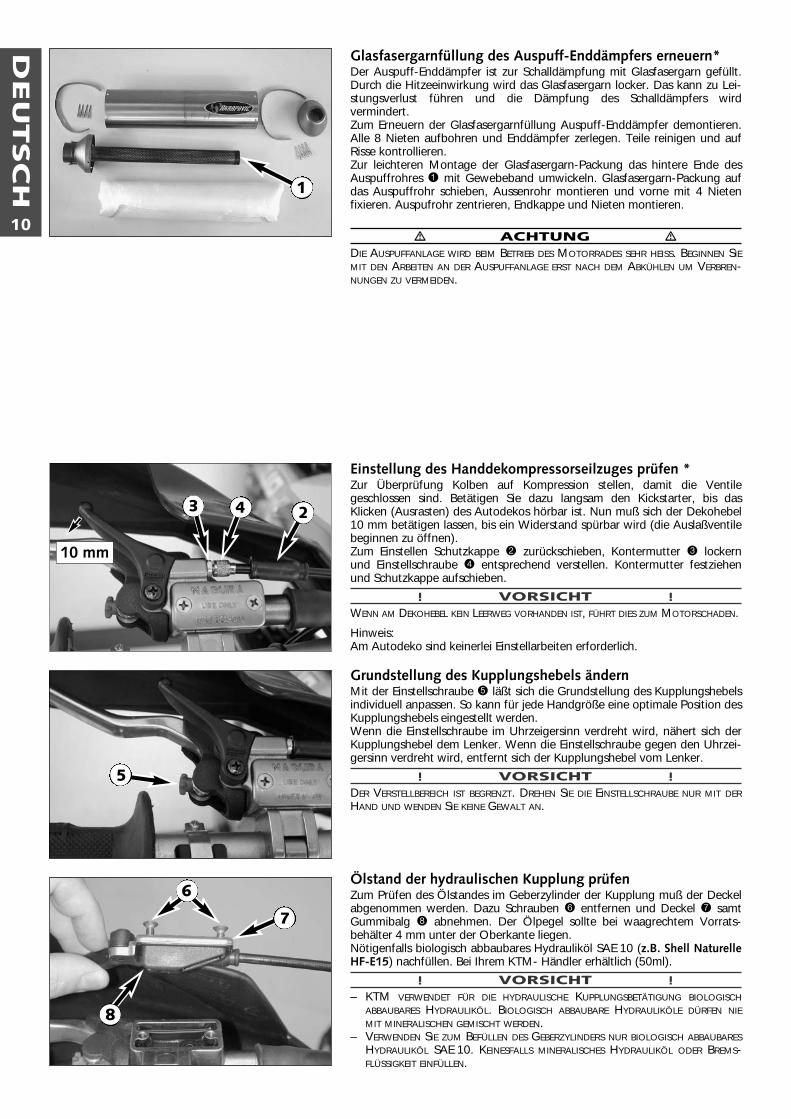
Einstellung des Handdekompressorseilzuges prüfen *Zur Überprüfung Kolben auf Kompression stellen, damit die Ventilegeschlossen sind. Betätigen Sie dazu langsam den Kickstarter, bis dasKlicken (Ausrasten) des Autodekos hörbar ist. Nun muß sich der Dekohebel10 mm betätigen lassen, bis ein Widerstand spürbar wird (die Auslaßventilebeginnen zu öffnen). Zum Einstellen Schutzkappe 2 zurückschieben, Kontermutter 3 lockernund Einstellschraube 4 entsprechend verstellen. Kontermutter festziehenund Schutzkappe aufschieben.
! VORSICHT !WENN AM DEKOHEBEL KEIN LEERWEG VORHANDEN IST, FÜHRT DIES ZUM MOTORSCHADEN.
Hinweis:Am Autodeko sind keinerlei Einstellarbeiten erforderlich.
Grundstellung des Kupplungshebels ändern Mit der Einstellschraube 5 läßt sich die Grundstellung des Kupplungshebelsindividuell anpassen. So kann für jede Handgröße eine optimale Position desKupplungshebels eingestellt werden. Wenn die Einstellschraube im Uhrzeigersinn verdreht wird, nähert sich derKupplungshebel dem Lenker. Wenn die Einstellschraube gegen den Uhrzei-gersinn verdreht wird, entfernt sich der Kupplungshebel vom Lenker.
! VORSICHT !DER VERSTELLBEREICH IST BEGRENZT. DREHEN SIE DIE EINSTELLSCHRAUBE NUR MIT DERHAND UND WENDEN SIE KEINE GEWALT AN.
Ölstand der hydraulischen Kupplung prüfenZum Prüfen des Ölstandes im Geberzylinder der Kupplung muß der Deckelabgenommen werden. Dazu Schrauben 6 entfernen und Deckel 7 samtGummibalg 8 abnehmen. Der Ölpegel sollte bei waagrechtem Vorrats-behälter 4 mm unter der Oberkante liegen. Nötigenfalls biologisch abbaubares Hydrauliköl SAE 10 (z.B. Shell NaturelleHF-E15) nachfüllen. Bei Ihrem KTM- Händler erhältlich (50ml).
! VORSICHT !– KTM VERWENDET FÜR DIE HYDRAULISCHE KUPPLUNGSBETÄTIGUNG BIOLOGISCH
ABBAUBARES HYDRAULIKÖL. BIOLOGISCH ABBAUBARE HYDRAULIKÖLE DÜRFEN NIEMIT MINERALISCHEN GEMISCHT WERDEN.
– VERWENDEN SIE ZUM BEFÜLLEN DES GEBERZYLINDERS NUR BIOLOGISCH ABBAUBARESHYDRAULIKÖL SAE 10. KEINESFALLS MINERALISCHES HYDRAULIKÖL ODER BREMS-FLÜSSIGKEIT EINFÜLLEN.
10 mm
3
7
1
4 2
5
6
8
DEU
TSC
H
11
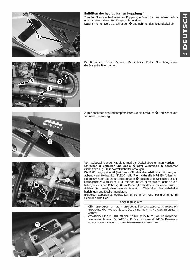
Entlüften der hydraulischen Kupplung *Zum Entlüften der hydraulischen Kupplung müssen Sie den unteren Krüm-mer und den rechten Enddämpfer abmontieren. Dazu entfernen Sie die 2 Schrauben 1 und nehmen den Seitendeckel ab.
Den Krümmer entfernen Sie indem Sie die beiden Federn 2 aushängen unddie Schraube 3 entfernen.
Zum Abnehmen des Enddämpfers lösen Sie die Schraube 4 und ziehen die-sen nach hinten weg.
Vom Geberzylinder der Kupplung muß der Deckel abgenommen werden.Schrauben 6 entfernen und Deckel 7 samt Gummibalg 8 abnehmen(siehe Seite 10). Öl im Vorratsbehälter absaugen. Die Entlüftungsspritze 9 (bei Ihrem KTM-Händler erhältlich) mit biologischabbaubarem Hydrauliköl SAE 10 (z.B. Shell Naturelle HF-E15) füllen. AmNehmerzylinder die Entlüftungsschraube bk lockern und Schlauch der Ent-lüftungsspritze aufstecken. Nun mit der Entlüftungsspritze so lange Öl ein-füllen, bis aus der Bohrung bl im Geberzylinder das Öl blasenfrei austritt.Achten Sie darauf, dass kein Öl überläuft. Ölstand im Vorratsbehälterberichtigen und Deckel montieren.Biologisch abbaubares Hydrauliköl ist bei Ihrem KTM-Händler in 50 mlGebinden erhältlich.
! VORSICHT !– KTM VERWENDET FÜR DIE HYDRAULISCHE KUPPLUNGSBETÄTIGUNG BIOLOGISCH
ABBAUBARES HYDRAULIKÖL. SOLCHE ÖLE DÜRFEN NIE MIT MINERALISCHEN GEMISCHTWERDEN.
– VERWENDEN SIE ZUM BEFÜLLEN DER HYDRAULISCHEN KUPPLUNG NUR BIOLOGISCHABBAUBARES HYDRAULIKÖL SAE 10 (Z.B. SHELL NATURELLE HF-E15). KEINESFALLSMINERALISCHES HYDRAULIKÖL ODER BREMSFLÜSSIGKEIT EINFÜLLEN.
9
1
2
2
3
4
10
11
DEU
TSC
H
12
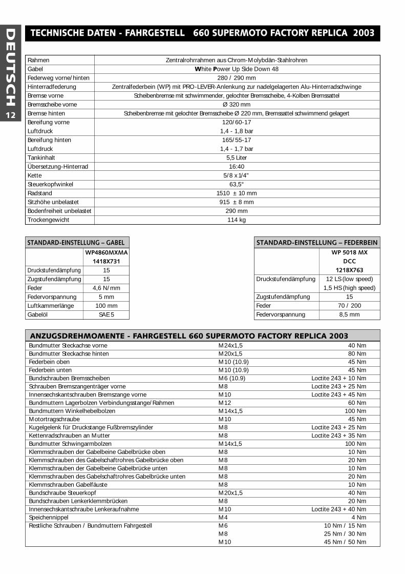
WP 5018 MXDCC
1218X763Druckstufendämpfung 12 LS (low speed)
1,5 HS (high speed)Zugstufendämpfung 15Feder 70 / 200Federvorspannung 8,5 mm
STANDARD-EINSTELLUNG – FEDERBEINWP4860MXMA
1418X731Druckstufendämpfung 15Zugstufendämpfung 15Feder 4,6 N/mmFedervorspannung 5 mmLuftkammerlänge 100 mmGabelöl SAE 5
STANDARD-EINSTELLUNG – GABEL
TECHNISCHE DATEN - FAHRGESTELL 660 SUPERMOTO FACTORY REPLICA 2003
Rahmen Zentralrohrrahmen aus Chrom-Molybdän-StahlrohrenGabel White Power Up Side Down 48Federweg vorne/hinten 280 / 290 mmHinterradfederung Zentralfederbein (WP) mit PRO-LEVER-Anlenkung zur nadelgelagerten Alu-HinterradschwingeBremse vorne Scheibenbremse mit schwimmender, gelochter Bremsscheibe, 4-Kolben BremssattelBremsscheibe vorne Ø 320 mmBremse hinten Scheibenbremse mit gelochter Bremsscheibe Ø 220 mm, Bremssattel schwimmend gelagertBereifung vorne 120/60-17Luftdruck 1,4 - 1,8 barBereifung hinten 165/55-17Luftdruck 1,4 - 1,7 barTankinhalt 5,5 LiterÜbersetzung-Hinterrad 16:40Kette 5/8 x1/4"Steuerkopfwinkel 63,5°Radstand 1510 ± 10 mmSitzhöhe unbelastet 915 ± 8 mmBodenfreiheit unbelastet 290 mmTrockengewicht 114 kg
Bundmutter Steckachse vorne M24x1,5 40 NmBundmutter Steckachse hinten M20x1,5 80 NmFederbein oben M10 (10.9) 45 NmFederbein unten M10 (10.9) 45 NmBundschrauben Bremsscheiben M6 (10.9) Loctite 243 + 10 NmSchrauben Bremszangenträger vorne M8 Loctite 243 + 25 NmInnensechskantschrauben Bremszange vorne M10 Loctite 243 + 45 NmBundmuttern Lagerbolzen Verbindungsstange/Rahmen M12 60 NmBundmuttern Winkelhebelbolzen M14x1,5 100 NmMotortragschraube M10 45 NmKugelgelenk für Druckstange Fußbremszylinder M8 Loctite 243 + 25 NmKettenradschrauben an Mutter M8 Loctite 243 + 35 NmBundmutter Schwingarmbolzen M14x1,5 100 NmKlemmschrauben der Gabelbeine Gabelbrücke oben M8 10 NmKlemmschrauben des Gabelschaftrohres Gabelbrücke oben M8 20 NmKlemmschrauben der Gabelbeine Gabelbrücke unten M8 10 NmKlemmschrauben des Gabelschaftrohres Gabelbrücke unten M8 20 NmKlemmschrauben Gabelfäuste M8 10 NmBundschraube Steuerkopf M20x1,5 40 NmBundschrauben Lenkerklemmbrücken M8 20 NmInnensechskantschraube Lenkeraufnahme M10 Loctite 243 + 40 NmSpeichennippel M4 4 NmRestliche Schrauben / Bundmuttern Fahrgestell M6 10 Nm / 15 Nm
M8 25 Nm / 30 NmM10 45 Nm / 50 Nm
ANZUGSDREHMOMENTE - FAHRGESTELL 660 SUPERMOTO FACTORY REPLICA 2003
DEU
TSC
H
13
660 SUPERMOTOFACTORY REPLICA
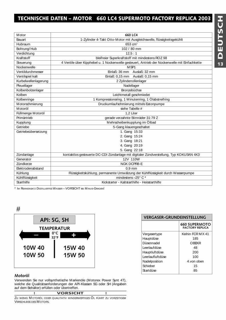
VERGASER-GRUNDEINSTELLUNG
VergasertypeHauptdüseDüsennadelLeerlaufdüseHauptluftdüseLeerlaufluftdüseNadelpositionSchieberStartdüse
Keihin FCR MX 41185
OBEKR48200100
4.von oben1585
#
� �– +0°C32°F
15W 4015W 50
10W 4010W 50
API: SG, SHTEMPERATUR
TECHNISCHE DATEN – MOTOR 660 LC4 SUPERMOTO FACTORY REPLICA 2003
Motor 660 LC4 Bauart 1-Zylinder 4-Takt Otto-Motor mit Ausgleichswelle, flüssigkeitsgekühltHubraum 653 cm3
Bohrung/Hub 102 / 80 mmVerdichtung 12,5 : 1Kraftstoff bleifreier Superkraftstoff mit mindestens ROZ 98Steuerung 4 Ventile über Kipphebel u. 1 Nockenwelle gesteuert, Antrieb der Nockenwelle mit EinfachketteNockenwelle MSP1Ventildurchmesser Einlaß: 36 mm Auslaß: 32 mmVentilspiel kalt Einlaß: 0,15 mm Auslaß: 0,15 mmKurbelwellenlagerung 2 ZylinderrollenlagerPleuellager NadellagerKolbenbolzenlager BronzebüchseKolben Leichtmetall geschmiedetKolbenringe 1 Kompressionsring, 1 Minutenring, 1 ÖlabstreifringMotorschmierung Druckumlaufschmierung mittels EatonpumpeMotoröl siehe Tabelle #Füllmenge Motoröl 1,2 LiterPrimärtrieb gerade verzahnte Stirnräder 31:79 ZKupplung Mehrscheibenkupplung im ÖlbadGetriebe 5-Gang klauengeschaltetGetriebeübersetzung 1. Gang 15:33
2. Gang 15:243. Gang 18:214. Gang 20:195. Gang 22:18
Zündanlage kontaktlos gesteuerte DC-CDI Zündanlage mit digitaler Zündverstellung, Typ KOKUSAN 4K3Generator 12V 110WZündkerze NGK DCPR8-EElektrodenabstand 0,9 mmKühlung Flüssigkeitskühlung, permanente Umwälzung der Kühlflüssigkeit durch WasserpumpeKühlflüssigkeit mindestens –25° C *Starthilfe Kickstarter - Kaltstarthilfe - Heisstarthilfe
MotorölVerwenden Sie nur vollsynthetische Markenöle (Motorex Power Synt 4T),welche die Qualitätsanforderungen der API-Klassen SG oder SH (Angabenauf dem Behälter) erfüllen oder übertreffen.
! VORSICHT !ZU WENIG MOTORÖL ODER QUALITATIV MINDERWERTIGES ÖL FÜHRT ZU VORZEITIGEMVERSCHLEISS DES MOTORS.
* IM RENNEINSATZ DESTILLIERTES WASSER – VORSICHT BEI MINUS-GRADEN!
DEU
TSC
H
14
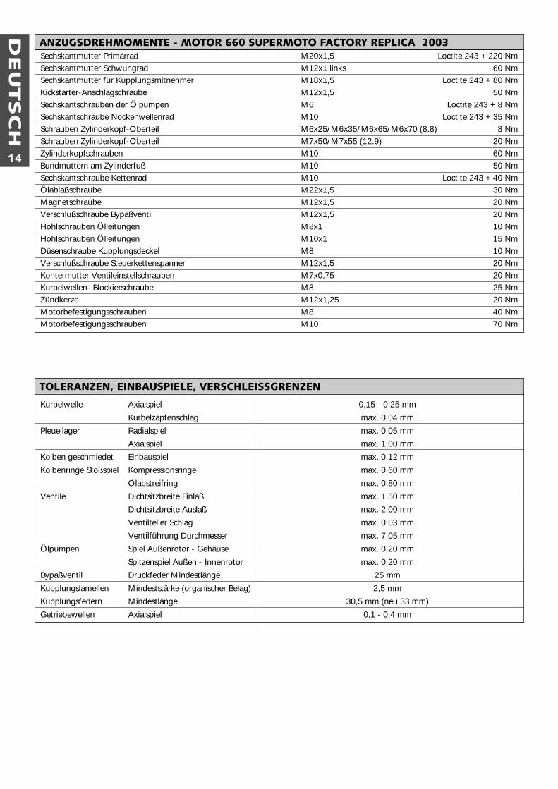
Sechskantmutter Primärrad M20x1,5 Loctite 243 + 220 NmSechskantmutter Schwungrad M12x1 links 60 NmSechskantmutter für Kupplungsmitnehmer M18x1,5 Loctite 243 + 80 NmKickstarter-Anschlagschraube M12x1,5 50 NmSechskantschrauben der Ölpumpen M6 Loctite 243 + 8 NmSechskantschraube Nockenwellenrad M10 Loctite 243 + 35 NmSchrauben Zylinderkopf-Oberteil M6x25/M6x35/M6x65/M6x70 (8.8) 8 NmSchrauben Zylinderkopf-Oberteil M7x50/M7x55 (12.9) 20 NmZylinderkopfschrauben M10 60 NmBundmuttern am Zylinderfuß M10 50 NmSechskantschraube Kettenrad M10 Loctite 243 + 40 NmÖlablaßschraube M22x1,5 30 NmMagnetschraube M12x1,5 20 NmVerschlußschraube Bypaßventil M12x1,5 20 NmHohlschrauben Ölleitungen M8x1 10 NmHohlschrauben Ölleitungen M10x1 15 NmDüsenschraube Kupplungsdeckel M8 10 NmVerschlußschraube Steuerkettenspanner M12x1,5 20 NmKontermutter Ventileinstellschrauben M7x0,75 20 NmKurbelwellen- Blockierschraube M8 25 NmZündkerze M12x1,25 20 NmMotorbefestigungsschrauben M8 40 NmMotorbefestigungsschrauben M10 70 Nm
ANZUGSDREHMOMENTE - MOTOR 660 SUPERMOTO FACTORY REPLICA 2003
Kurbelwelle Axialspiel 0,15 - 0,25 mm
Kurbelzapfenschlag max. 0,04 mm
Pleuellager Radialspiel max. 0,05 mm
Axialspiel max. 1,00 mm
Kolben geschmiedet Einbauspiel max. 0,12 mm
Kolbenringe Stoßspiel Kompressionsringe max. 0,60 mm
Ölabstreifring max. 0,80 mm
Ventile Dichtsitzbreite Einlaß max. 1,50 mm
Dichtsitzbreite Auslaß max. 2,00 mm
Ventilteller Schlag max. 0,03 mm
Ventilführung Durchmesser max. 7,05 mm
Ölpumpen Spiel Außenrotor - Gehäuse max. 0,20 mm
Spitzenspiel Außen - Innenrotor max. 0,20 mm
Bypaßventil Druckfeder Mindestlänge 25 mm
Kupplungslamellen Mindeststärke (organischer Belag) 2,5 mm
Kupplungsfedern Mindestlänge 30,5 mm (neu 33 mm)
Getriebewellen Axialspiel 0,1 - 0,4 mm
TOLERANZEN, EINBAUSPIELE, VERSCHLEISSGRENZEN
DEU
TSC
H
15
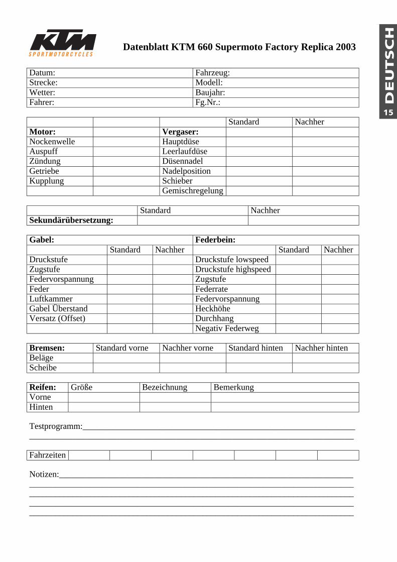
Datenblatt KTM 660 Supermoto Factory Replica 2003
Datum: Fahrzeug:Strecke: Modell:Wetter: Baujahr:Fahrer: Fg.Nr.:
Standard NachherMotor: Vergaser:Nockenwelle HauptdüseAuspuff LeerlaufdüseZündung DüsennadelGetriebe NadelpositionKupplung Schieber
Gemischregelung
Standard NachherSekundärübersetzung:
Gabel: Federbein:Standard Nachher Standard Nachher
Druckstufe Druckstufe lowspeedZugstufe Druckstufe highspeedFedervorspannung ZugstufeFeder FederrateLuftkammer FedervorspannungGabel Überstand HeckhöheVersatz (Offset) Durchhang
Negativ Federweg
Bremsen: Standard vorne Nachher vorne Standard hinten Nachher hintenBelägeScheibe
Reifen: Größe Bezeichnung BemerkungVorneHinten
Testprogramm:__________________________________________________________________________________________________________________________________________
Fahrzeiten
Notizen:________________________________________________________________________________________________________________________________________________________________________________________________________________________________________________________________________________________________________________________________________________________________________________
EN
GLIS
H
16
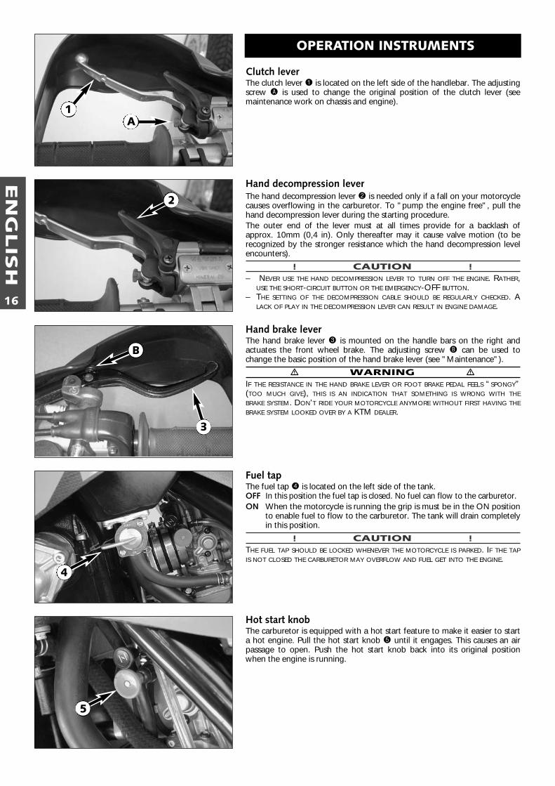
Clutch lever The clutch lever 1 is located on the left side of the handlebar. The adjustingscrew A is used to change the original position of the clutch lever (seemaintenance work on chassis and engine).
Hand decompression leverThe hand decompression lever 2 is needed only if a fall on your motorcyclecauses overflowing in the carburetor. To "pump the engine free", pull thehand decompression lever during the starting procedure.The outer end of the lever must at all times provide for a backlash ofapprox. 10mm (0,4 in). Only thereafter may it cause valve motion (to be recognized by the stronger resistance which the hand decompression levelencounters).
! CAUTION !– NEVER USE THE HAND DECOMPRESSION LEVER TO TURN OFF THE ENGINE. RATHER,
USE THE SHORT-CIRCUIT BUTTON OR THE EMERGENCY-OFF BUTTON.– THE SETTING OF THE DECOMPRESSION CABLE SHOULD BE REGULARLY CHECKED. A
LACK OF PLAY IN THE DECOMPRESSION LEVER CAN RESULT IN ENGINE DAMAGE.
Hand brake leverThe hand brake lever 3 is mounted on the handle bars on the right andactuates the front wheel brake. The adjusting screw B can be used tochange the basic position of the hand brake lever (see "Maintenance").
� WARNING �IF THE RESISTANCE IN THE HAND BRAKE LEVER OR FOOT BRAKE PEDAL FEELS “SPONGY”(TOO MUCH GIVE), THIS IS AN INDICATION THAT SOMETHING IS WRONG WITH THEBRAKE SYSTEM. DON’T RIDE YOUR MOTORCYCLE ANYMORE WITHOUT FIRST HAVING THEBRAKE SYSTEM LOOKED OVER BY A KTM DEALER.
Fuel tapThe fuel tap 4 is located on the left side of the tank.OFF In this position the fuel tap is closed. No fuel can flow to the carburetor. ON When the motorcycle is running the grip is must be in the ON position
to enable fuel to flow to the carburetor. The tank will drain completelyin this position.
! CAUTION !THE FUEL TAP SHOULD BE LOCKED WHENEVER THE MOTORCYCLE IS PARKED. IF THE TAPIS NOT CLOSED THE CARBURETOR MAY OVERFLOW AND FUEL GET INTO THE ENGINE.
Hot start knobThe carburetor is equipped with a hot start feature to make it easier to starta hot engine. Pull the hot start knob 5 until it engages. This causes an airpassage to open. Push the hot start knob back into its original positionwhen the engine is running.
OPERATION INSTRUMENTS
1A
2
3
B
4
5
EN
GLIS
H
17
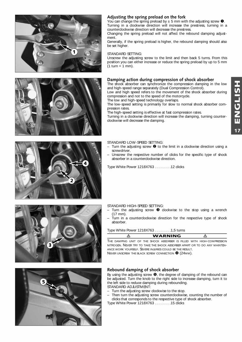
Adjusting the spring preload on the forkYou can change the spring preload by ± 5 mm with the adjusting screw 1.Turning in a clockwise direction will increase the prestress, turning in acounterclockwise direction will decrease the prestress.Changing the spring preload will not affect the rebound damping adjust-ment.Generally, if the spring preload is higher, the rebound damping should alsobe set higher.
STANDARD SETTING:Unscrew the adjusting screw to the limit and then back 5 turns. From thisposition you can either increase or reduce the spring preload by up to 5 mm(1 turn = 1 mm).
Damping action during compression of shock absorberThe shock absorber can synchronize the compression damping in the lowand high-speed range separately (Dual Compression Control).Low and high speed refers to the movement of the shock absorber duringcompression and not to the speed of the motorcycle.The low and high-speed technology overlaps.The low-speed setting is primarily for slow to normal shock absorber com-pression rates.The high-speed setting is effective at fast compression rates.Turning in a clockwise direction will increase the damping, turning counter-clockwise will decrease the damping.
STANDARD LOW-SPEED SETTING:– Turn the adjusting screw 2 to the limit in a clockwise direction using a
screwdriver.– Unscrew the respective number of clicks for the specific type of shock
absorber in a counterclockwise direction.
Type White Power 1218X763 . . . . . . . .12 clicks
STANDARD HIGH-SPEED SETTING:– Turn the adjusting screw 3 clockwise to the stop using a wrench
(17 mm).– Turn in a counterclockwise direction for the respective type of shock
absorber.
Type White Power 1218X763 . . . . . . . .1,5 turns
� WARNING �THE DAMPING UNIT OF THE SHOCK ABSORBER IS FILLED WITH HIGH-COMPRESSIONNITROGEN. NEVER TRY TO TAKE THE SHOCK ABSORBER APART OR TO DO ANY MAINTEN-ANCE WORK YOURSELF. SEVERE INJURIES COULD BE THE RESULT.NEVER UNSCREW THE BLACK SCREW CONNECTION 4 (24MM).
Rebound damping of shock absorberBy using the adjusting screw 5, the degree of damping of the rebound canbe adjusted. Turn the knob to the right side to increase damping, turn it tothe left side to reduce damping during rebounding.STANDARD ADJUSTMENT:– Turn the adjusting screw clockwise to the stop.– Then turn the adjusting screw counterclockwise, counting the number of
clicks that corresponds to the respective type of shock absorber.Type White Power 1218X763 . . . . . . . .15 clicks
1
2
3
4
5
EN
GLIS
H
18
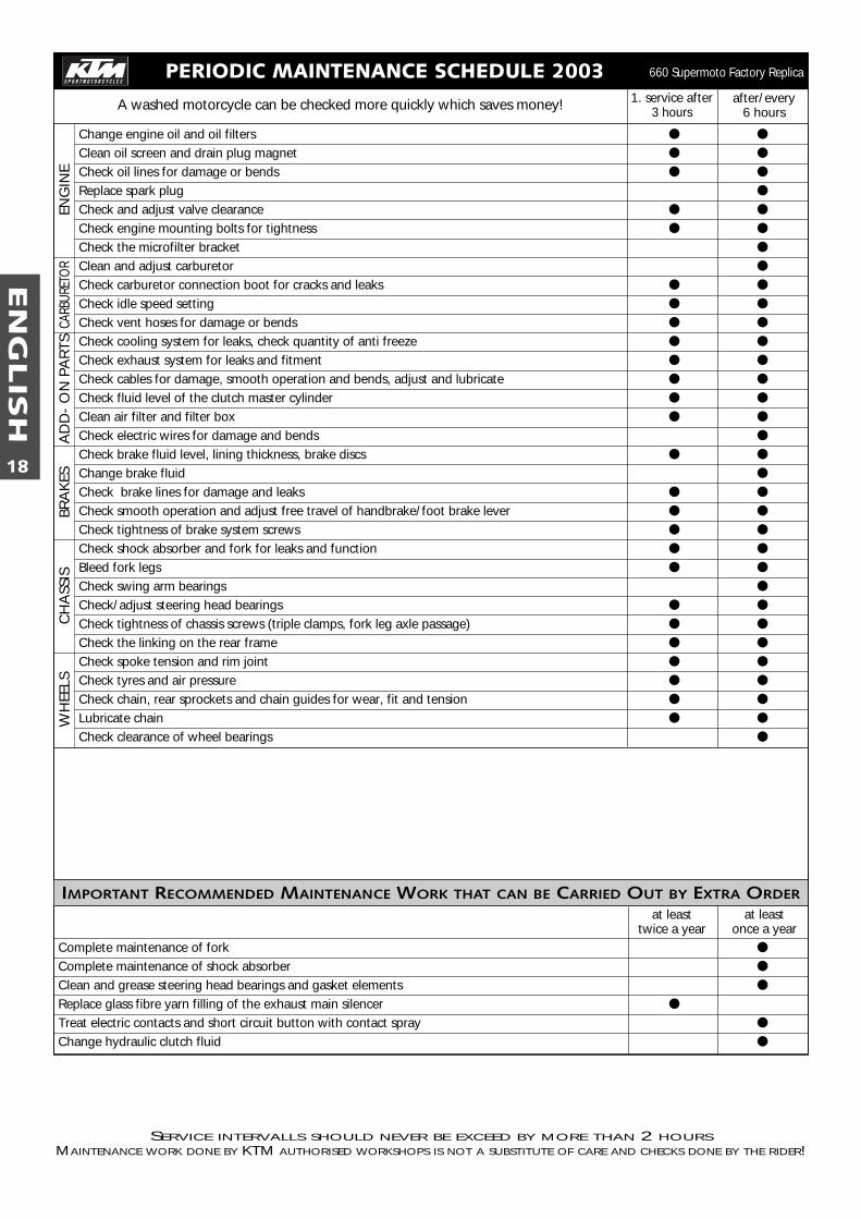
PERIODIC MAINTENANCE SCHEDULE 20031. service after
3 hours
SERVICE INTERVALLS SHOULD NEVER BE EXCEED BY MORE THAN 2 HOURSMAINTENANCE WORK DONE BY KTM AUTHORISED WORKSHOPS IS NOT A SUBSTITUTE OF CARE AND CHECKS DONE BY THE RIDER!
A washed motorcycle can be checked more quickly which saves money!
Change engine oil and oil filters ● ●
Clean oil screen and drain plug magnet ● ●
Check oil lines for damage or bends ● ●
Replace spark plug ●
Check and adjust valve clearance ● ●
Check engine mounting bolts for tightness ● ●
Check the microfilter bracket ●
Clean and adjust carburetor ●
Check carburetor connection boot for cracks and leaks ● ●
Check idle speed setting ● ●
Check vent hoses for damage or bends ● ●
Check cooling system for leaks, check quantity of anti freeze ● ●
Check exhaust system for leaks and fitment ● ●
Check cables for damage, smooth operation and bends, adjust and lubricate ● ●
Check fluid level of the clutch master cylinder ● ●
Clean air filter and filter box ● ●
Check electric wires for damage and bends ●
Check brake fluid level, lining thickness, brake discs ● ●
Change brake fluid ●
Check brake lines for damage and leaks ● ●
Check smooth operation and adjust free travel of handbrake/foot brake lever ● ●
Check tightness of brake system screws ● ●
Check shock absorber and fork for leaks and function ● ●
Bleed fork legs ● ●
Check swing arm bearings ●
Check/adjust steering head bearings ● ●
Check tightness of chassis screws (triple clamps, fork leg axle passage) ● ●
Check the linking on the rear frame ● ●
Check spoke tension and rim joint ● ●
Check tyres and air pressure ● ●
Check chain, rear sprockets and chain guides for wear, fit and tension ● ●
Lubricate chain ● ●
Check clearance of wheel bearings ●
IMPORTANT RECOMMENDED MAINTENANCE WORK THAT CAN BE CARRIED OUT BY EXTRA ORDER
Complete maintenance of fork ●
Complete maintenance of shock absorber ●
Clean and grease steering head bearings and gasket elements ●
Replace glass fibre yarn filling of the exhaust main silencer ●
Treat electric contacts and short circuit button with contact spray ●
Change hydraulic clutch fluid ●
WH
EELS
CH
ASS
ISBR
AK
ESA
DD
- O
N P
AR
TSCA
RBUR
ETO
REN
GIN
E660 Supermoto Factory Replica
at leasttwice a year
after/every6 hours
at leastonce a year
EN
GLIS
H
19
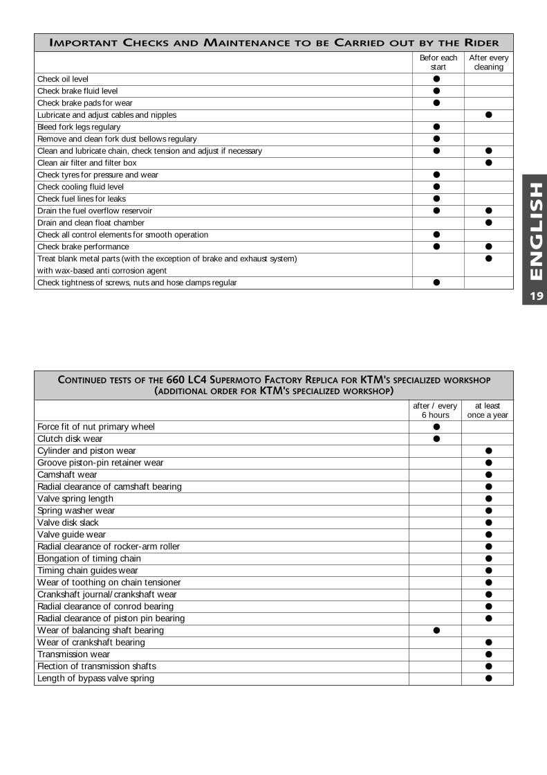
IMPORTANT CHECKS AND MAINTENANCE TO BE CARRIED OUT BY THE RIDER
Check oil level ●
Check brake fluid level ●
Check brake pads for wear ●
Lubricate and adjust cables and nipples ●
Bleed fork legs regulary ●
Remove and clean fork dust bellows regulary ●
Clean and lubricate chain, check tension and adjust if necessary ● ●
Clean air filter and filter box ●
Check tyres for pressure and wear ●
Check cooling fluid level ●
Check fuel lines for leaks ●
Drain the fuel overflow reservoir ● ●
Drain and clean float chamber ●
Check all control elements for smooth operation ●
Check brake performance ● ●
Treat blank metal parts (with the exception of brake and exhaust system) ●
with wax-based anti corrosion agentCheck tightness of screws, nuts and hose clamps regular ●
After everycleaning
Befor eachstart
CONTINUED TESTS OF THE 660 LC4 SUPERMOTO FACTORY REPLICA FOR KTM'S SPECIALIZED WORKSHOP(ADDITIONAL ORDER FOR KTM'S SPECIALIZED WORKSHOP)
Force fit of nut primary wheel ●
Clutch disk wear ●
Cylinder and piston wear ●
Groove piston-pin retainer wear ●
Camshaft wear ●
Radial clearance of camshaft bearing ●
Valve spring length ●
Spring washer wear ●
Valve disk slack ●
Valve guide wear ●
Radial clearance of rocker-arm roller ●
Elongation of timing chain ●
Timing chain guides wear ●
Wear of toothing on chain tensioner ●
Crankshaft journal/crankshaft wear ●
Radial clearance of conrod bearing ●
Radial clearance of piston pin bearing ●
Wear of balancing shaft bearing ●
Wear of crankshaft bearing ●
Transmission wear ●
Flection of transmission shafts ●
Length of bypass valve spring ●
after / every6 hours
at leastonce a year
EN
GLIS
H
20
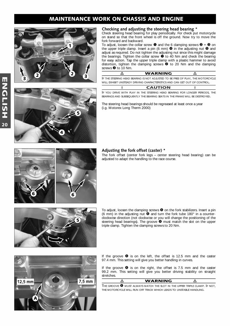
Checking and adjusting the steering head bearing *Check steering head bearing for play periodically. For check put motorcycleon stand so that the front wheel is off the ground. Now try to move thefork forward and backward.To adjust, loosen the collar screw 1 and the 6 clamping screws 2 + 3 onthe upper triple clamp. Insert a pin (6 mm) 4 in the adjusting nut 5 andadjust as required. Do not tighten the adjusting nut since this might damagethe bearings. Tighten the collar screw 1 to 40 Nm and check the bearingfor easy action. Tap the upper triple clamp with a plastic hammer to avoiddistortion, tighten the clamping screws 2 to 20 Nm and the clamping screws 3 to 10 Nm.
� WARNING �IF THE STEERING HEAD BEARING IS NOT ADJUSTED TO BE FREE OF PLAY, THE MOTORCYCLEWILL EXHIBIT UNSTEADY DRIVING CHARACTERISTICS AND CAN GET OUT OF CONTROL.
! CAUTION !IF YOU DRIVE WITH PLAY IN THE STEERING HEAD BEARING FOR LONGER PERIODS, THEBEARINGS AND SUBSEQUENTLY THE BEARING SEATS IN THE FRAME WILL BE DESTROYED.
The steering head bearings should be regreased at least once a year (i.g. Motorex Long Therm 2000)
Adjusting the fork offset (caster) *The fork offset (center fork legs – center steering head bearing) can beadjusted to adapt the handling to the race course.
To adjust, loosen the clamping screws 5 on the fork stabilizers. Insert a pin(6 mm) in the adjusting nut 6 and turn the fork tube 180° in a counter-clockwise direction (not clockwise or you will change the positioning of thesteering head bearings). The groove A must match the slot on the uppertriple clamp. Tighten the clamping screws to 20 Nm.
If the groove A is on the left, the offset is 12.5 mm and the caster 97.4 mm. This setting will give you better handling in curves.
If the groove A is on the right, the offset is 7.5 mm and the caster 99.2 mm. This setting will give you better driving stability on straight stretches.
� WARNING �THE GROOVE A MUST ALWAYS MATCH THE SLOT IN THE UPPER TRIPLE CLAMP. IF NOT,THE MOTORCYCLE WILL RUN OFF TRACK WHICH LEADS TO UNSTABLE HANDLING.
MAINTENANCE WORK ON CHASSIS AND ENGINE
1
22
4
12,5 mm 7,5 mm
A
3 3
5
66
5
EN
GLIS
H
21
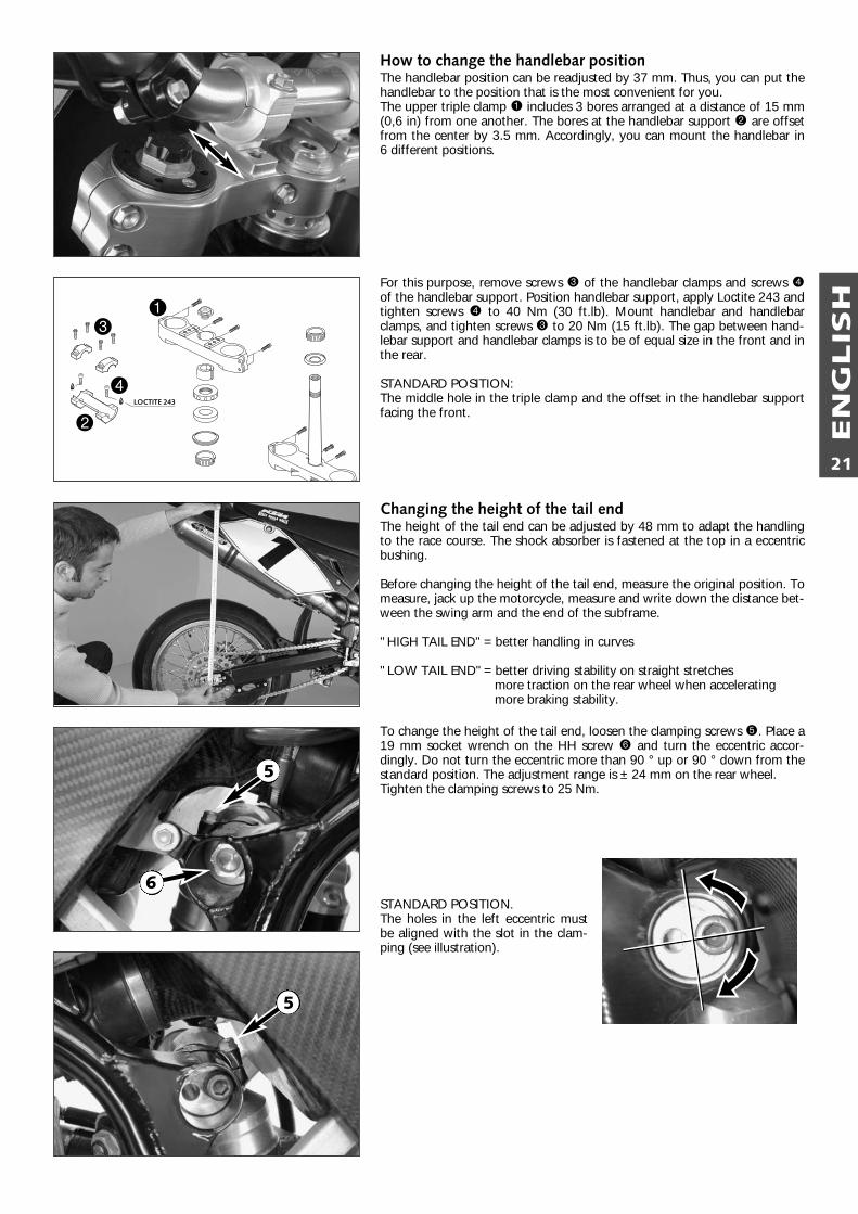
How to change the handlebar positionThe handlebar position can be readjusted by 37 mm. Thus, you can put thehandlebar to the position that is the most convenient for you. The upper triple clamp 1 includes 3 bores arranged at a distance of 15 mm(0,6 in) from one another. The bores at the handlebar support 2 are offsetfrom the center by 3.5 mm. Accordingly, you can mount the handlebar in 6 different positions.
For this purpose, remove screws 3 of the handlebar clamps and screws 4of the handlebar support. Position handlebar support, apply Loctite 243 andtighten screws 4 to 40 Nm (30 ft.lb). Mount handlebar and handlebarclamps, and tighten screws 3 to 20 Nm (15 ft.lb). The gap between hand-lebar support and handlebar clamps is to be of equal size in the front and inthe rear.
STANDARD POSITION:The middle hole in the triple clamp and the offset in the handlebar supportfacing the front.
Changing the height of the tail endThe height of the tail end can be adjusted by 48 mm to adapt the handlingto the race course. The shock absorber is fastened at the top in a eccentricbushing.
Before changing the height of the tail end, measure the original position. Tomeasure, jack up the motorcycle, measure and write down the distance bet-ween the swing arm and the end of the subframe.
"HIGH TAIL END"= better handling in curves
"LOW TAIL END"= better driving stability on straight stretchesmore traction on the rear wheel when acceleratingmore braking stability.
To change the height of the tail end, loosen the clamping screws 5. Place a19 mm socket wrench on the HH screw 6 and turn the eccentric accor-dingly. Do not turn the eccentric more than 90 ° up or 90 ° down from thestandard position. The adjustment range is ± 24 mm on the rear wheel.Tighten the clamping screws to 25 Nm.
STANDARD POSITION.The holes in the left eccentric mustbe aligned with the slot in the clam-ping (see illustration).
LOCTITE 243
1
2
3
4
5
5
6
EN
GLIS
H
22
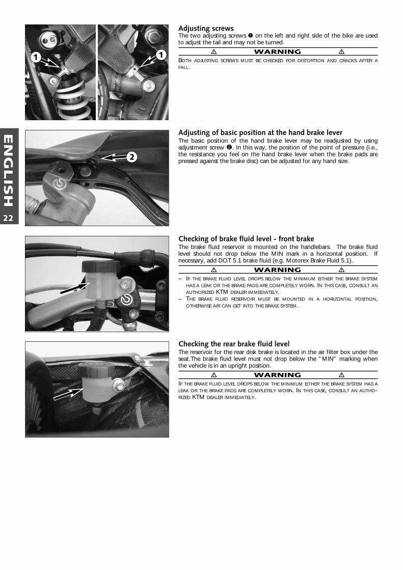
Adjusting screwsThe two adjusting screws 1 on the left and right side of the bike are usedto adjust the tail and may not be turned.
� WARNING �BOTH ADJUSTING SCREWS MUST BE CHECKED FOR DISTORTION AND CRACKS AFTER AFALL.
Adjusting of basic position at the hand brake leverThe basic position of the hand brake lever may be readjusted by usingadjustment screw 2. In this way, the position of the point of pressure (i.e.,the resistance you feel on the hand brake lever when the brake pads arepressed against the brake disc) can be adjusted for any hand size.
Checking of brake fluid level - front brakeThe brake fluid reservoir is mounted on the handlebars. The brake fluidlevel should not drop below the MIN mark in a horizontal position. Ifnecessary, add DOT 5.1 brake fluid (e.g. Motorex Brake Fluid 5.1).
� WARNING �– IF THE BRAKE FLUID LEVEL DROPS BELOW THE MINIMUM EITHER THE BRAKE SYSTEM
HAS A LEAK OR THE BRAKE PADS ARE COMPLETELY WORN. IN THIS CASE, CONSULT ANAUTHORIZED KTM DEALER IMMEDIATELY.
– THE BRAKE FLUID RESERVOIR MUST BE MOUNTED IN A HORIZONTAL POSITION,OTHERWISE AIR CAN GET INTO THE BRAKE SYSTEM.
Checking the rear brake fluid levelThe reservoir for the rear disk brake is located in the air filter box under theseat.The brake fluid level must not drop below the ”MlN” marking whenthe vehicle is in an upright position.
� WARNING �IF THE BRAKE FLUID LEVEL DROPS BELOW THE MINIMUM EITHER THE BRAKE SYSTEM HAS ALEAK OR THE BRAKE PADS ARE COMPLETELY WORN. IN THIS CASE, CONSULT AN AUTHO-RIZED KTM DEALER IMMEDIATELY.
2
1 1
EN
GLIS
H
23
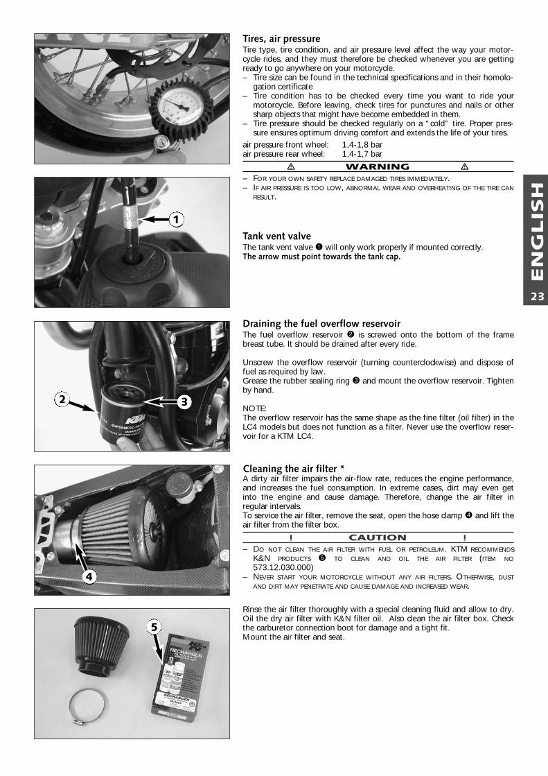
Tires, air pressureTire type, tire condition, and air pressure level affect the way your motor-cycle rides, and they must therefore be checked whenever you are gettingready to go anywhere on your motorcycle.– Tire size can be found in the technical specifications and in their homolo-
gation certificate– Tire condition has to be checked every time you want to ride your
motorcycle. Before leaving, check tires for punctures and nails or othersharp objects that might have become embedded in them.
– Tire pressure should be checked regularly on a “cold” tire. Proper pres-sure ensures optimum driving comfort and extends the life of your tires.
air pressure front wheel: 1,4-1,8 barair pressure rear wheel: 1,4-1,7 bar
� WARNING �– FOR YOUR OWN SAFETY REPLACE DAMAGED TIRES IMMEDIATELY.– IF AIR PRESSURE IS TOO LOW, ABNORMAL WEAR AND OVERHEATING OF THE TIRE CAN
RESULT.
Tank vent valveThe tank vent valve 1 will only work properly if mounted correctly.The arrow must point towards the tank cap.
Draining the fuel overflow reservoirThe fuel overflow reservoir 2 is screwed onto the bottom of the framebreast tube. It should be drained after every ride.
Unscrew the overflow reservoir (turning counterclockwise) and dispose offuel as required by law.Grease the rubber sealing ring 3 and mount the overflow reservoir. Tightenby hand.
NOTE:The overflow reservoir has the same shape as the fine filter (oil filter) in theLC4 models but does not function as a filter. Never use the overflow reser-voir for a KTM LC4.
Cleaning the air filter *A dirty air filter impairs the air-flow rate, reduces the engine performance,and increases the fuel consumption. In extreme cases, dirt may even getinto the engine and cause damage. Therefore, change the air filter in regular intervals.To service the air filter, remove the seat, open the hose clamp 4 and lift theair filter from the filter box.
! CAUTION !– DO NOT CLEAN THE AIR FILTER WITH FUEL OR PETROLEUM. KTM RECOMMENDS
K&N PRODUCTS 5 TO CLEAN AND OIL THE AIR FILTER (ITEM NO573.12.030.000)
– NEVER START YOUR MOTORCYCLE WITHOUT ANY AIR FILTERS. OTHERWISE, DUSTAND DIRT MAY PENETRATE AND CAUSE DAMAGE AND INCREASED WEAR.
Rinse the air filter thoroughly with a special cleaning fluid and allow to dry.Oil the dry air filter with K&N filter oil. Also clean the air filter box. Checkthe carburetor connection boot for damage and a tight fit.Mount the air filter and seat.
3
1
2
4
5
EN
GLIS
H
24
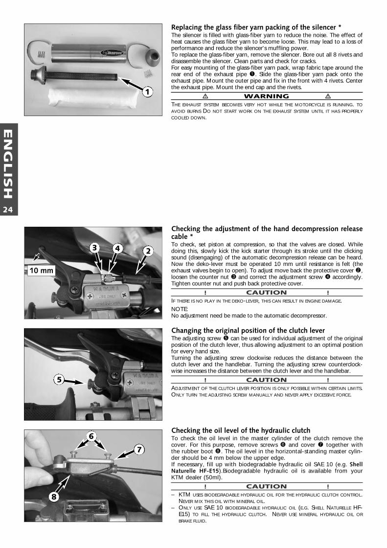
Replacing the glass fiber yarn packing of the silencer *The silencer is filled with glass-fiber yarn to reduce the noise. The effect ofheat causes the glass fiber yarn to become loose. This may lead to a loss ofperformance and reduce the silencer's muffling power.To replace the glass-fiber yarn, remove the silencer. Bore out all 8 rivets anddisassemble the silencer. Clean parts and check for cracks.For easy mounting of the glass-fiber yarn pack, wrap fabric tape around therear end of the exhaust pipe 1. Slide the glass-fiber yarn pack onto theexhaust pipe. Mount the outer pipe and fix in the front with 4 rivets. Centerthe exhaust pipe. Mount the end cap and the rivets.
� WARNING �THE EXHAUST SYSTEM BECOMES VERY HOT WHILE THE MOTORCYCLE IS RUNNING. TOAVOID BURNS DO NOT START WORK ON THE EXHAUST SYSTEM UNTIL IT HAS PROPERLYCOOLED DOWN.
Checking the adjustment of the hand decompression releasecable *To check, set piston at compression, so that the valves are closed. Whiledoing this, slowly kick the kick starter through its stroke until the clickingsound (disengaging) of the automatic decompression release can be heard.Now the deko-lever must be operated 10 mm until resistance is felt (theexhaust valves begin to open). To adjust move back the protective cover 2,loosen the counter nut 3 and correct the adjustment screw 4 accordingly.Tighten counter nut and push back protective cover.
! CAUTION !IF THERE IS NO PLAY IN THE DEKO-LEVER, THIS CAN RESULT IN ENGINE DAMAGE.NOTE:No adjustment need be made to the automatic decompressor.
Changing the original position of the clutch leverThe adjusting screw 5 can be used for individual adjustment of the originalposition of the clutch lever, thus allowing adjustment to an optimal positionfor every hand size.Turning the adjusting screw clockwise reduces the distance between theclutch lever and the handlebar. Turning the adjusting screw counterclock-wise increases the distance between the clutch lever and the handlebar.
! CAUTION !ADJUSTMENT OF THE CLUTCH LEVER POSITION IS ONLY POSSIBLE WITHIN CERTAIN LIMITS.ONLY TURN THE ADJUSTING SCREW MANUALLY AND NEVER APPLY EXCESSIVE FORCE.
Checking the oil level of the hydraulic clutch To check the oil level in the master cylinder of the clutch remove thecover. For this purpose, remove screws 6 and cover 7 together withthe rubber boot 8. The oil level in the horizontal-standing master cylin-der should be 4 mm below the upper edge. If necessary, fill up with biodegradable hydraulic oil SAE 10 (e.g. ShellNaturelle HF-E15).Biodegradable hydraulic oil is available from yourKTM dealer (50ml).
! CAUTION !– KTM USES BIODEGRADABLE HYDRAULIC OIL FOR THE HYDRAULIC CLUTCH CONTROL.
NEVER MIX THIS OIL WITH MINERAL OIL.– ONLY USE SAE 10 BIODEGRADABLE HYDRAULIC OIL (E.G. SHELL NATURELLE HF-
E15) TO FILL THE HYDRAULIC CLUTCH. NEVER USE MINERAL HYDRAULIC OIL ORBRAKE FLUID.
10 mm
3
7
1
4 2
5
6
8
EN
GLIS
H
25
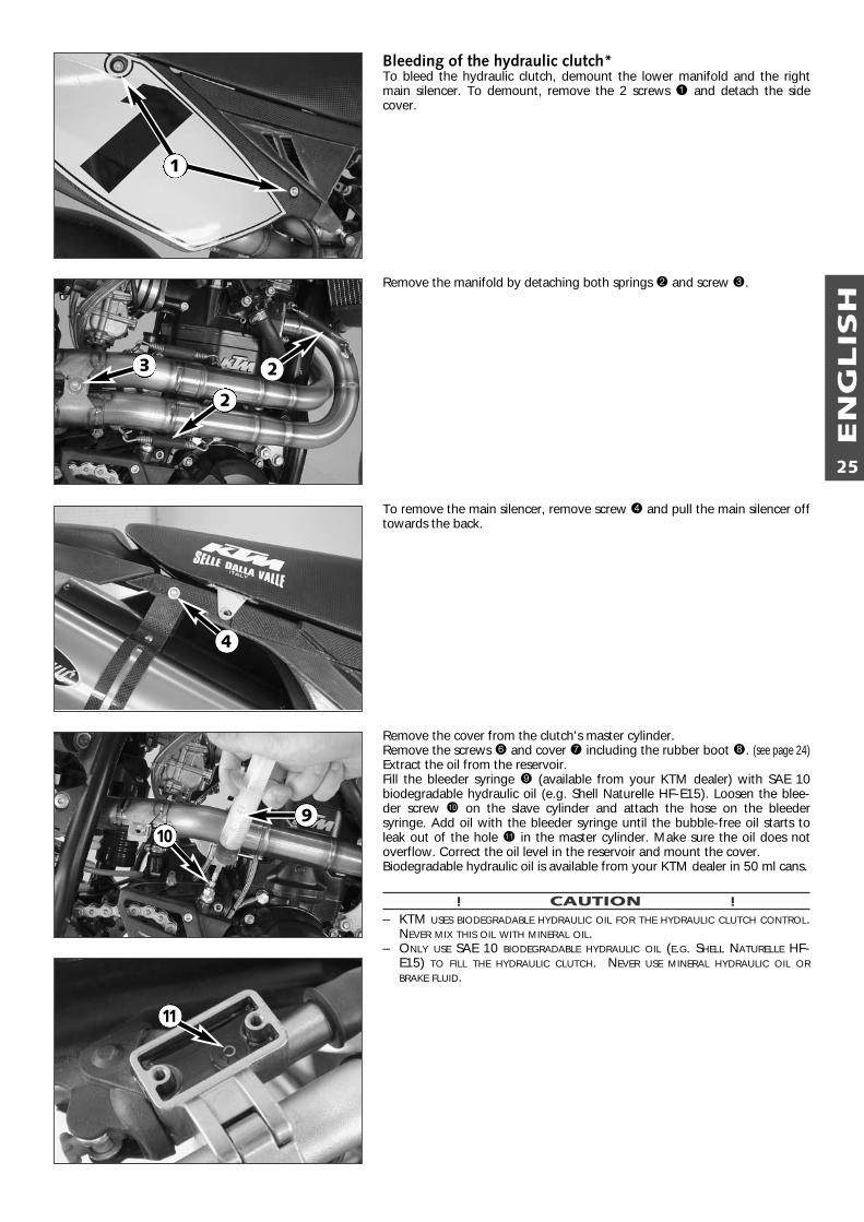
Bleeding of the hydraulic clutch*To bleed the hydraulic clutch, demount the lower manifold and the rightmain silencer. To demount, remove the 2 screws 1 and detach the sidecover.
Remove the manifold by detaching both springs 2 and screw 3.
To remove the main silencer, remove screw 4 and pull the main silencer offtowards the back.
Remove the cover from the clutch's master cylinder.Remove the screws 6 and cover 7 including the rubber boot 8. (see page 24)Extract the oil from the reservoir. Fill the bleeder syringe 9 (available from your KTM dealer) with SAE 10biodegradable hydraulic oil (e.g. Shell Naturelle HF-E15). Loosen the blee-der screw bk on the slave cylinder and attach the hose on the bleedersyringe. Add oil with the bleeder syringe until the bubble-free oil starts toleak out of the hole bl in the master cylinder. Make sure the oil does notoverflow. Correct the oil level in the reservoir and mount the cover.Biodegradable hydraulic oil is available from your KTM dealer in 50 ml cans.
! CAUTION !– KTM USES BIODEGRADABLE HYDRAULIC OIL FOR THE HYDRAULIC CLUTCH CONTROL.
NEVER MIX THIS OIL WITH MINERAL OIL.– ONLY USE SAE 10 BIODEGRADABLE HYDRAULIC OIL (E.G. SHELL NATURELLE HF-
E15) TO FILL THE HYDRAULIC CLUTCH. NEVER USE MINERAL HYDRAULIC OIL ORBRAKE FLUID.
9
1
2
2
3
4
10
11
EN
GLIS
H
26
Collar nut front axle M24x1,5 40 Nm (30ft.lb)
Collar nut rear axle M20x1,5 80 Nm (59ft.lb)
Shock absorber top M10 (10.9) 45 Nm (33ft.lb)
Shock absorber bottom M10 (10.9) 45 Nm (33ft.lb)
Collar screws brake disks M6 (10.9) Loctite 243 + 10Nm (7ft.lb)
Screws brake caliper support front M8 Loctite 243 + 25 Nm (19ft.lb)
Screws brake caliper front M10 Loctite 243 + 45 Nm (33ft.lb)
Bearing bolt linkage arm/frame M12 60 Nm (44ft.lb)
Collar nuts rocker arm bolts M14x1,5 100 Nm (74ft.lb)
Engine mounting screw M10 45 Nm (33ft.lb)
Ball joint for push rod foot brake cylinder M8 Loctite 243 + 25 Nm (19ft.lb)
Sprocket screws on nuts M8 Loctite 243 + 35 Nm (25ft.lb)
Collar nut swingarm bolt M14x1,5 100 Nm (74ft.lb)
Clamping screws fork legs top triple clamp M8 10 Nm (7ft.lb)
Clamping screws steering stem top triple clamp M8 20 Nm (15ft.lb)
Clamping screws fork legs bottom triple clamp M8 10 Nm (7ft.lb)
Clamping screws steering stem bottom triple clamp M8 20 Nm (15ft.lb)
Clamping screws fork stubs M8 10 Nm (7ft.lb)
Collar screw steering head M20x1,5 40 Nm (30ft.lb)
Screws handlebar clamp M8 20 Nm (15ft.lb)
Allan head screw handle bar support M10 Loctite 243 + 40 Nm (30ft.lb)
Spoke nipple M4 4 Nm (3ft.lb)
Other screws/collar nuts on chassis M6 10 Nm/15 Nm (7ft.lb)/(11ft.lb)
M8 25 Nm/30 Nm (19ft.lb)/(22ft.lb)
M10 45 Nm/50 Nm (33ft.lb)/(37ft.lb)
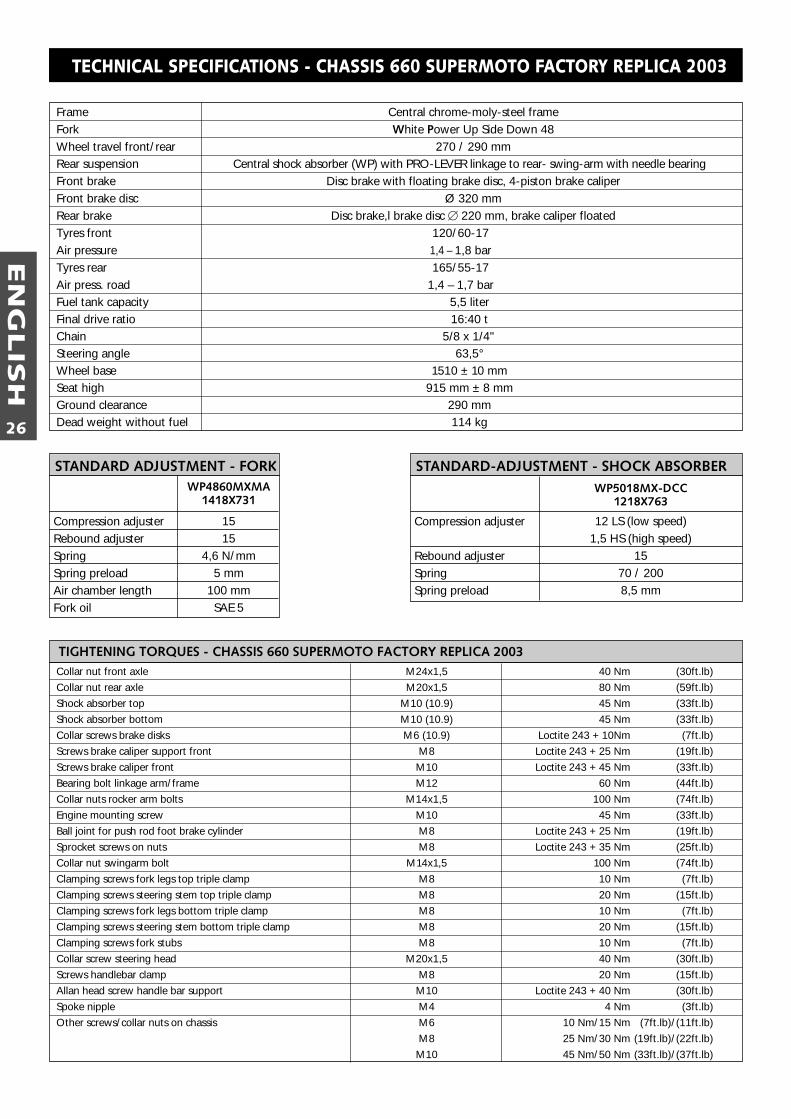
TIGHTENING TORQUES - CHASSIS 660 SUPERMOTO FACTORY REPLICA 2003
Frame Central chrome-moly-steel frameFork White Power Up Side Down 48Wheel travel front/rear 270 / 290 mmRear suspension Central shock absorber (WP) with PRO-LEVER linkage to rear- swing-arm with needle bearingFront brake Disc brake with floating brake disc, 4-piston brake caliperFront brake disc Ø 320 mmRear brake Disc brake,l brake disc � 220 mm, brake caliper floatedTyres front 120/60-17Air pressure 1,4 – 1,8 barTyres rear 165/55-17Air press. road 1,4 – 1,7 barFuel tank capacity 5,5 literFinal drive ratio 16:40 tChain 5/8 x 1/4"Steering angle 63,5°Wheel base 1510 ± 10 mmSeat high 915 mm ± 8 mmGround clearance 290 mmDead weight without fuel 114 kg
TECHNICAL SPECIFICATIONS - CHASSIS 660 SUPERMOTO FACTORY REPLICA 2003
WP4860MXMA1418X731
Compression adjuster 15Rebound adjuster 15Spring 4,6 N/mmSpring preload 5 mmAir chamber length 100 mmFork oil SAE 5
STANDARD ADJUSTMENT - FORKWP5018MX-DCC
1218X763
Compression adjuster 12 LS (low speed)1,5 HS (high speed)
Rebound adjuster 15Spring 70 / 200Spring preload 8,5 mm
STANDARD-ADJUSTMENT - SHOCK ABSORBER
EN
GLIS
H
27
660 SUPERMOTOFACTORY REPLICA
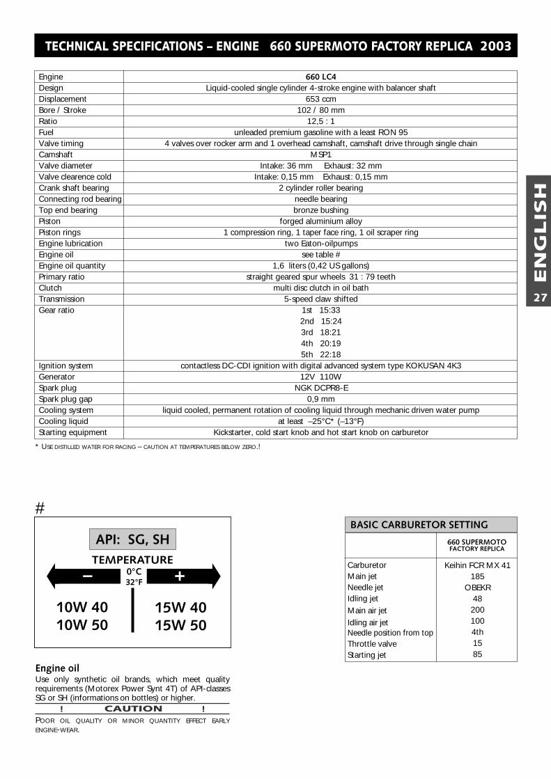
BASIC CARBURETOR SETTING
CarburetorMain jetNeedle jetIdling jetMain air jetIdling air jetNeedle position from topThrottle valveStarting jet
Keihin FCR MX 41185
OBEKR48
2001004th1585
Engine 660 LC4Design Liquid-cooled single cylinder 4-stroke engine with balancer shaftDisplacement 653 ccmBore / Stroke 102 / 80 mmRatio 12,5 : 1Fuel unleaded premium gasoline with a least RON 95Valve timing 4 valves over rocker arm and 1 overhead camshaft, camshaft drive through single chainCamshaft MSP1Valve diameter Intake: 36 mm Exhaust: 32 mm Valve clearence cold Intake: 0,15 mm Exhaust: 0,15 mmCrank shaft bearing 2 cylinder roller bearingConnecting rod bearing needle bearingTop end bearing bronze bushingPiston forged aluminium alloyPiston rings 1 compression ring, 1 taper face ring, 1 oil scraper ringEngine lubrication two Eaton-oilpumpsEngine oil see table #Engine oil quantity 1,6 liters (0,42 US gallons)Primary ratio straight geared spur wheels 31 : 79 teethClutch multi disc clutch in oil bathTransmission 5-speed claw shiftedGear ratio 1st 15:33
2nd 15:243rd 18:214th 20:195th 22:18
Ignition system contactless DC-CDI ignition with digital advanced system type KOKUSAN 4K3Generator 12V 110WSpark plug NGK DCPR8-ESpark plug gap 0,9 mmCooling system liquid cooled, permanent rotation of cooling liquid through mechanic driven water pumpCooling liquid at least –25°C* (–13°F)Starting equipment Kickstarter, cold start knob and hot start knob on carburetor
TECHNICAL SPECIFICATIONS – ENGINE 660 SUPERMOTO FACTORY REPLICA 2003
� �– +0°C32°F
15W 4015W 50
10W 4010W 50
API: SG, SHTEMPERATURE
Engine oilUse only synthetic oil brands, which meet qualityrequirements (Motorex Power Synt 4T) of API-classesSG or SH (informations on bottles) or higher.
! CAUTION !POOR OIL QUALITY OR MINOR QUANTITY EFFECT EARLYENGINE-WEAR.
#
* USE DISTILLED WATER FOR RACING – CAUTION AT TEMPERATURES BELOW ZERO.!
EN
GLIS
H
28
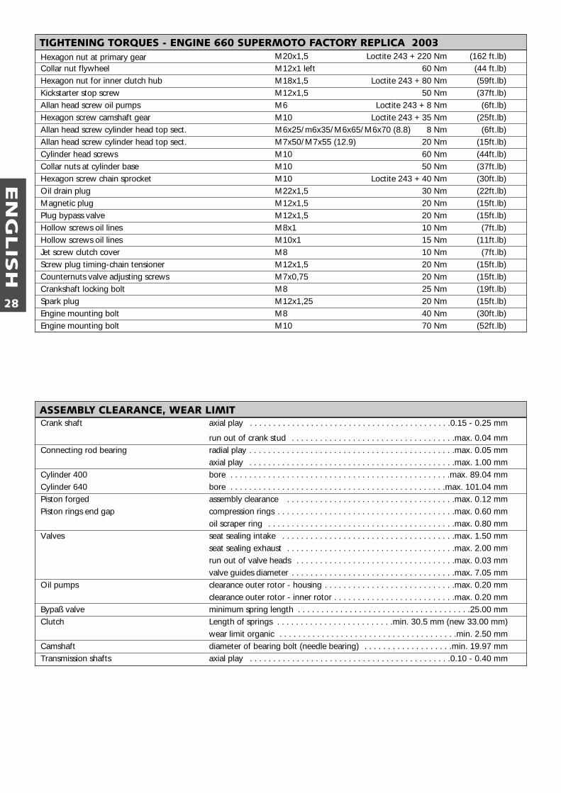
Hexagon nut at primary gear M20x1,5 Loctite 243 + 220 Nm (162 ft.lb)Collar nut flywheel M12x1 left 60 Nm (44 ft.lb)Hexagon nut for inner clutch hub M18x1,5 Loctite 243 + 80 Nm (59ft.lb)Kickstarter stop screw M12x1,5 50 Nm (37ft.lb)Allan head screw oil pumps M6 Loctite 243 + 8 Nm (6ft.lb)Hexagon screw camshaft gear M10 Loctite 243 + 35 Nm (25ft.lb)Allan head screw cylinder head top sect. M6x25/m6x35/M6x65/M6x70 (8.8) 8 Nm (6ft.lb)Allan head screw cylinder head top sect. M7x50/M7x55 (12.9) 20 Nm (15ft.lb)Cylinder head screws M10 60 Nm (44ft.lb)Collar nuts at cylinder base M10 50 Nm (37ft.lb)Hexagon screw chain sprocket M10 Loctite 243 + 40 Nm (30ft.lb)Oil drain plug M22x1,5 30 Nm (22ft.lb)Magnetic plug M12x1,5 20 Nm (15ft.lb)Plug bypass valve M12x1,5 20 Nm (15ft.lb)Hollow screws oil lines M8x1 10 Nm (7ft.lb)Hollow screws oil lines M10x1 15 Nm (11ft.lb)Jet screw clutch cover M8 10 Nm (7ft.lb)Screw plug timing-chain tensioner M12x1,5 20 Nm (15ft.lb)Counternuts valve adjusting screws M7x0,75 20 Nm (15ft.lb)Crankshaft locking bolt M8 25 Nm (19ft.lb)Spark plug M12x1,25 20 Nm (15ft.lb)Engine mounting bolt M8 40 Nm (30ft.lb)Engine mounting bolt M10 70 Nm (52ft.lb)
TIGHTENING TORQUES - ENGINE 660 SUPERMOTO FACTORY REPLICA 2003
ASSEMBLY CLEARANCE, WEAR LIMITCrank shaft axial play . . . . . . . . . . . . . . . . . . . . . . . . . . . . . . . . . . . . . . . . . . .0.15 - 0.25 mm
run out of crank stud . . . . . . . . . . . . . . . . . . . . . . . . . . . . . . . . . . .max. 0.04 mmConnecting rod bearing radial play . . . . . . . . . . . . . . . . . . . . . . . . . . . . . . . . . . . . . . . . . . . .max. 0.05 mm
axial play . . . . . . . . . . . . . . . . . . . . . . . . . . . . . . . . . . . . . . . . . . . .max. 1.00 mmCylinder 400 bore . . . . . . . . . . . . . . . . . . . . . . . . . . . . . . . . . . . . . . . . . . . . . . .max. 89.04 mmCylinder 640 bore . . . . . . . . . . . . . . . . . . . . . . . . . . . . . . . . . . . . . . . . . . . . . .max. 101.04 mmPiston forged assembly clearance . . . . . . . . . . . . . . . . . . . . . . . . . . . . . . . . . . . .max. 0.12 mmPiston rings end gap compression rings . . . . . . . . . . . . . . . . . . . . . . . . . . . . . . . . . . . . . .max. 0.60 mm
oil scraper ring . . . . . . . . . . . . . . . . . . . . . . . . . . . . . . . . . . . . . . . .max. 0.80 mmValves seat sealing intake . . . . . . . . . . . . . . . . . . . . . . . . . . . . . . . . . . . . .max. 1.50 mm
seat sealing exhaust . . . . . . . . . . . . . . . . . . . . . . . . . . . . . . . . . . . .max. 2.00 mmrun out of valve heads . . . . . . . . . . . . . . . . . . . . . . . . . . . . . . . . . .max. 0.03 mmvalve guides diameter . . . . . . . . . . . . . . . . . . . . . . . . . . . . . . . . . . .max. 7.05 mm
Oil pumps clearance outer rotor - housing . . . . . . . . . . . . . . . . . . . . . . . . . . . .max. 0.20 mmclearance outer rotor - inner rotor . . . . . . . . . . . . . . . . . . . . . . . . . .max. 0.20 mm
Bypaß valve minimum spring length . . . . . . . . . . . . . . . . . . . . . . . . . . . . . . . . . . . . .25.00 mmClutch Length of springs . . . . . . . . . . . . . . . . . . . . . . . . .min. 30.5 mm (new 33.00 mm)
wear limit organic . . . . . . . . . . . . . . . . . . . . . . . . . . . . . . . . . . . . . .min. 2.50 mmCamshaft diameter of bearing bolt (needle bearing) . . . . . . . . . . . . . . . . . . .min. 19.97 mmTransmission shafts axial play . . . . . . . . . . . . . . . . . . . . . . . . . . . . . . . . . . . . . . . . . . .0.10 - 0.40 mm
EN
GLIS
H
29
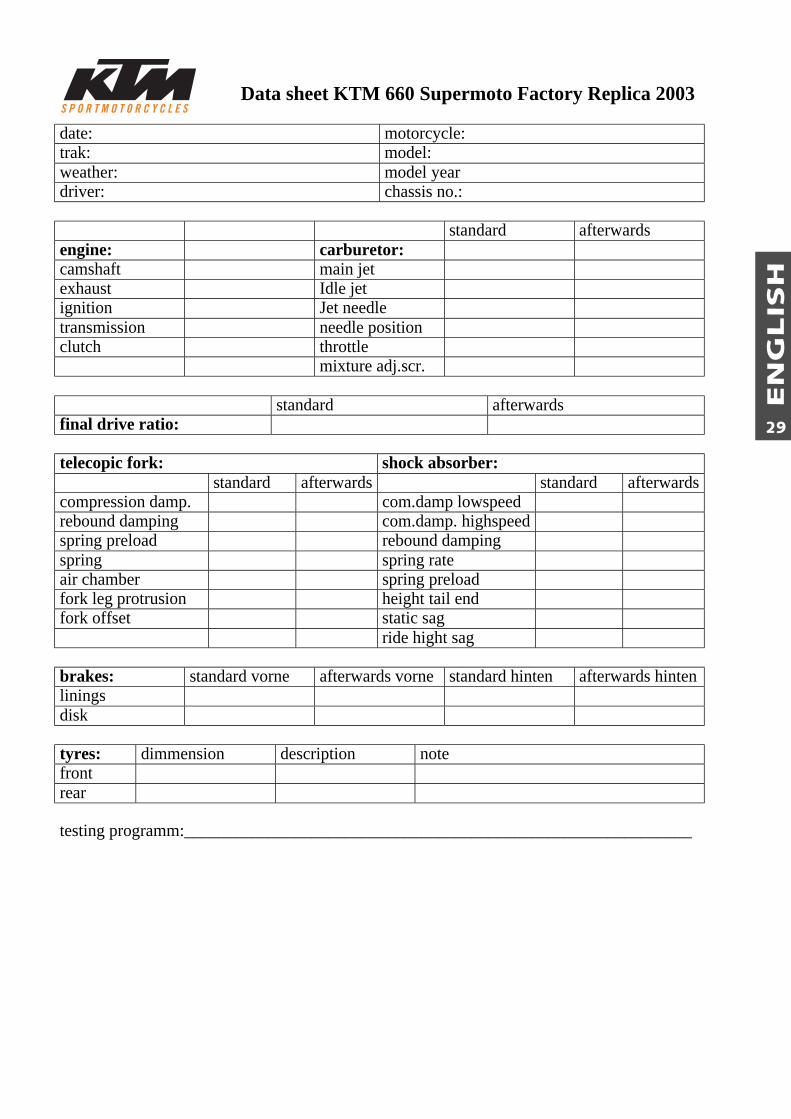
Data sheet KTM 660 Supermoto Factory Replica 2003
date: motorcycle:trak: model:weather: model yeardriver: chassis no.:
standard afterwardsengine: carburetor:camshaft main jetexhaust Idle jetignition Jet needletransmission needle positionclutch throttle
mixture adj.scr.
standard afterwardsfinal drive ratio:
telecopic fork: shock absorber:standard afterwards standard afterwards
compression damp. com.damp lowspeedrebound damping com.damp. highspeedspring preload rebound dampingspring spring rateair chamber spring preloadfork leg protrusion height tail endfork offset static sag
ride hight sag
brakes: standard vorne afterwards vorne standard hinten afterwards hintenliningsdisk
tyres: dimmension description notefrontrear
testing programm:____________________________________________________________


KT
M S
PO
RT
MO
TO
RC
YC
LE A
G52
30 M
attig
hofe
nA
ustr
iaIn
tern
et: w
ww
.ktm
.at


![OC 3 - Stereochemie - JGU Blogs · 1,2,3 : die ersten drei Atome in der Ebene Weg & Reihenfolge nach CIP pR : im Uhrzeigersinn pS : gegen Uhrzeigersinn * 3 2 1 [2,2]-Paracyclophan](https://img.pdfslide.org/doc/110x75/5e1615e949de916396719d03/oc-3-stereochemie-jgu-blogs-123-die-ersten-drei-atome-in-der-ebene-weg-.jpg)