Embed Size (px)
Citation preview
Party
Sa - 15°C
°C
VRC-VCC
+10
+2
+3
-1
-2
-3
VRC 410
BEDIENUNGS- UND MONTAGEANLEITUNGOPERATING AND INSTALLATION INSTRUCTIONS
INSTRUCTIONS DE MONTAGE ET MANUEL D'UTILISATION
DE GB FR
2
Verehrte Kundin, geehrter Kunde!Mit dem Vaillant Regelgerät VRC 410haben Sie ein Spitzenprodukt aus demHause Vaillant erworben. Um alleVorteile des Gerätes richtig nutzen zukönnen, nehmen Sie sich ruhig ein paarMinuten Zeit und lesen Sie dieseBedienungsanleitung. Sie ist nichtkompliziert und gibt Ihnen nützliche Tipsund Tricks.Bitte bewahren Sie diese Anleitungsorgfältig auf und geben Sie sie einemevt. Nachbesitzer weiter.
Zu Ihrer Sicherheit!Alle Arbeiten am Gerät selbst und amGesamtsystem dürfen nur autorisierteFachleute durchführen!Bitte bedenken Sie, daß bei nichtfachgerecht ausgeführten ArbeitenGefahr für Leib und Leben bestehenkann.
TIPPS!
● Beachten Sie die werkseitigen Ein-stellungen auf Seite 22. Sind Siedamit zufrieden, brauchen Sie keineweiteren Einstellungen vorzunehmen.
● Nehmen Sie bei allen Einstellvor-gängen die Ausklappseiten amAnfang und am Ende dieser Anleitungzu Hilfe.
Dear customer!By choosing the VRC 410 thermostat youhave bought a high quality product fromVaillant. In order to familiarise yourselfwith all aspects of this thermostat it isrecommended that you take some timeand carefully read this instructionmanual. It is easy to understand and willgive you many useful hints.Please keep the manual in a safe placeand make sure that is handed over topossible next owners of the control.
For your safety!All repairs on the thermostat itself andyour overall system should always becarried out by authorised professionalsonly!Please take into consideration that non-professional interference with theappliance could threaten lives.
Hints!● Please note the list of settings which
have been already programmed intothe thermostat on page 14. If you arehappy with these settings no furtherprogramming is necessary.
● Refer to the folded pages at thebeginning and the end of this manualfor re-programming the thermostat.
Chère cliente, cher client!Avec le régulateur VRC 410 de Vaillant,vous venez d'acquérir un produit haut degamme. Pour pouvoir profiter aumaximum de tous les avantages del'appareil, n'hésitez pas à réserverquelques minutes à la lecture de ce moded'emploi. Il n'est pas compliqué et vousfournit des "tuyaux" bien utiles.Conservez soigneusement ce documentet donnez-le, le cas échéant, aupropriétaire ultérieur.
Pour votre sécurité!Sur l'appareil lui-même et sur l'ensembledu système, les travaux ne doivent êtreréalisés que par des spécialistesqualifiés!Risques corporels graves si les travaux nesont pas effectués selon les règles.
QUELQUES "TUYAUX"● Examinez les réglages effectués par le
constructeur (page 16). S’ils vousconviennent, vous n'avez pas besoind’en effectuer d'autres.
● Lors de tous les réglages, aidez-vousdes rabats du début et de la fin de cemode d'emploi.
DE GB FR
3
Party
Sa - 15°C
°C
VRC-VCC
+10
+2
+3
-1
-2
-3
Party
Sa - 15°C
°C
A B C D E F
HG
21
7 65
VRC-VC2_001/0
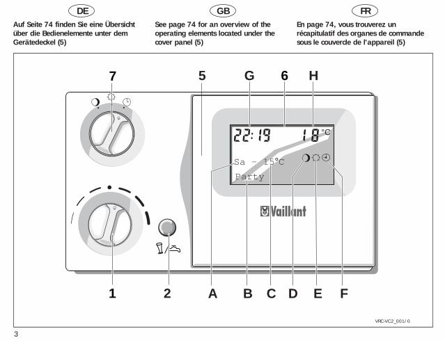
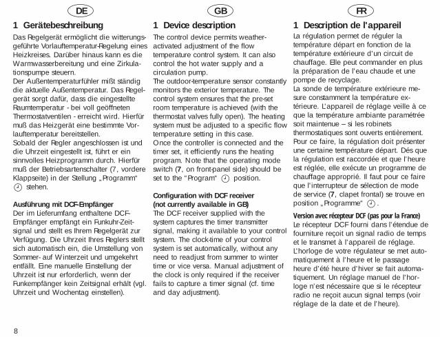
Auf Seite 74 finden Sie eine Übersichtüber die Bedienelemente unter demGerätedeckel (5)
See page 74 for an overview of the operating elements located under thecover panel (5)
En page 74, vous trouverez unrécapitulatif des organes de commandesous le couvercle de l'appareil (5)
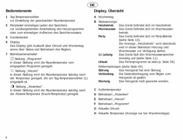
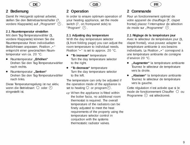
Bedienelemente1 Tag-Temperaturwähler
zur Einstellung der gewünschten Raumtemperatur.2 Partytaste/einmaliges Laden des Speichers
zur vorübergehenden Abschaltung des Heizprogrammsoder zum einmaligen Aufheizen des Speicherwassers.
5 Gerätedeckel6 Display
Das Display gibt Auskunft über Uhrzeit und Wochentagsowie über Status und Betriebsart des Reglers.
7 BetriebsartenschalterStellung „Programm“
In dieser Stellung wird die Raumtemperatur vomeingegeben Programm geregelt.
Stellung „Heizen“ In dieser Stellung wird die Raumtemperatur ständig nachder Temperatur geregelt, die am Tag-Temperaturwähler (1)eingestellt ist.
Stellung „Absenken“ .In dieser Stellung wird die Raumtemperatur ständig nachder Absenk-Temperatur (Nacht-Temperatur) geregelt.
Display, ÜbersichtA WochentagB Statusanzeige:
Heizbetrieb Das Gerät befindet sich im Heizbetrieb.Warmwasser Das Gerät befindet sich im Warmwasser-
betrieb.Party Das Gerät befindet sich im Party-Betrieb
(siehe Seite 10). Die Anzeige „Heizbetrieb“ wird überdeckt,weil in dieser Betriebart Heizung undWarmwasser zur Verfügung stehen.
1x Ladung Das Gerät lädt den Warmwasserspeichereinmalig auf (siehe Seite 11).
Urlaub Das Ferienprogramm ist aktiv.(s. Seite 36)Fehlermeldungen (siehe Seite 45)Störung Das Heizgerät hat eine StörungVerbindung Die Datenübertragung vom Regler zum
Heizgerät ist gestört.Wartung Das Heizgerät muß gewartet werden.
C AußentemperaturD Betriebsart „Absenken“E Betriebsart „Heizen“F Betriebsart „Programm“G Aktuelle UhrzeitH Aktuelle Temperatur (Anzeige nur bei Wandmontage)
DE
4
DE GB FR
5
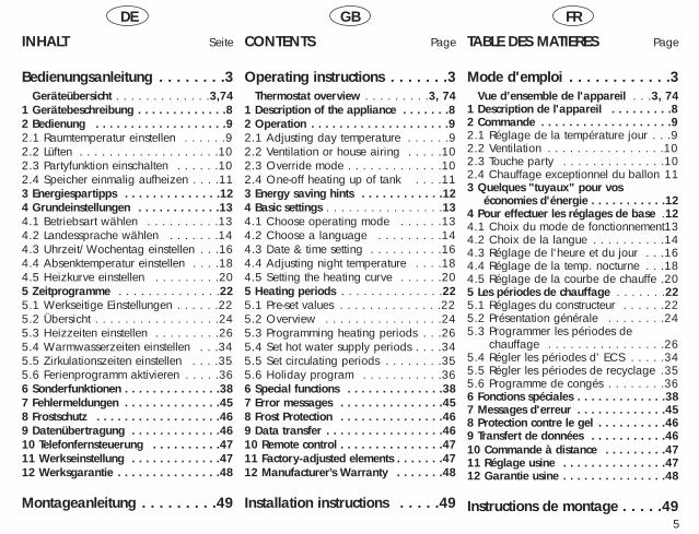
INHALT Seite
Bedienungsanleitung . . . . . . . .31 Geräteübersicht . . . . . . . . . . . . .3,741 Gerätebeschreibung . . . . . . . . . . . . .82 Bedienung . . . . . . . . . . . . . . . . . . .92.1 Raumtemperatur einstellen . . . . . .92.2 Lüften . . . . . . . . . . . . . . . . . . .102.3 Partyfunktion einschalten . . . . . .102.4 Speicher einmalig aufheizen . . . .113 Energiespartipps . . . . . . . . . . . . . .124 Grundeinstellungen . . . . . . . . . . . .134.1 Betriebsart wählen . . . . . . . . . .134.2 Landessprache wählen . . . . . . .144.3 Uhrzeit/Wochentag einstellen . . .164.4 Absenktemperatur einstellen . . . .184.5 Heizkurve einstellen . . . . . . . . .205 Zeitprogramme . . . . . . . . . . . . . .225.1 Werkseitige Einstellungen . . . . . .225.2 Übersicht . . . . . . . . . . . . . . . . .245.3 Heizzeiten einstellen . . . . . . . . .265.4 Warmwasserzeiten einstellen . . .345.5 Zirkulationszeiten einstellen . . . .355.6 Ferienprogramm aktivieren . . . . .366 Sonderfunktionen . . . . . . . . . . . . . .387 Fehlermeldungen . . . . . . . . . . . . . .458 Frostschutz . . . . . . . . . . . . . . . . . .469 Datenübertragung . . . . . . . . . . . . .4610 Telefonfernsteuerung . . . . . . . . . .4711 Werkseinstellung . . . . . . . . . . . . .4712 Werksgarantie . . . . . . . . . . . . . . .48
Montageanleitung . . . . . . . . .49
CONTENTS Page
Operating instructions . . . . . . .31 Thermostat overview . . . . . . . . .3, 741 Description of the appliance . . . . . . .82 Operation . . . . . . . . . . . . . . . . . . . .92.1 Adjusting day temperature . . . . . .92.2 Ventilation or house airing . . . . .102.3 Override mode . . . . . . . . . . . . .102.4 One-off heating up of tank . . . .113 Energy saving hints . . . . . . . . . . . .124 Basic settings . . . . . . . . . . . . . . . .134.1 Choose operating mode . . . . . .134.2 Choose a language . . . . . . . . .144.3 Date & time setting . . . . . . . . . .164.4 Adjusting night temperature . . . .184.5 Setting the heating curve . . . . . .205 Heating periods . . . . . . . . . . . . . .225.1 Pre-set values . . . . . . . . . . . . . .225.2 Overview . . . . . . . . . . . . . . . .245.3 Programming heating periods . . .265.4 Set hot water supply periods . . . .345.5 Set circulating periods . . . . . . . .355.6 Holiday program . . . . . . . . . . .366 Special functions . . . . . . . . . . . . . .387 Error messages . . . . . . . . . . . . . . .458 Frost Protection . . . . . . . . . . . . . . .469 Data transfer . . . . . . . . . . . . . . . . .4610 Remote control . . . . . . . . . . . . . . .4711 Factory-adjusted elements . . . . . . .4712 Manufacturer’s Warranty . . . . . . .48
Installation instructions . . . . .49
TABLE DES MATIERES Page
Mode d'emploi . . . . . . . . . . . .31 Vue d’ensemble de l'appareil . . .3, 741 Description de l'appareil . . . . . . . . .82 Commande . . . . . . . . . . . . . . . . . . .92.1 Réglage de la température jour . . .92.2 Ventilation . . . . . . . . . . . . . . . .102.3 Touche party . . . . . . . . . . . . . .102.4 Chauffage exceptionnel du ballon 113 Quelques "tuyaux" pour vos
économies d'énergie . . . . . . . . . . .124 Pour effectuer les réglages de base .124.1 Choix du mode de fonctionnement134.2 Choix de la langue . . . . . . . . . .144.3 Réglage de l'heure et du jour . . .164.4 Réglage de la temp. nocturne . . .184.5 Réglage de la courbe de chauffe .205 Les périodes de chauffage . . . . . . .225.1 Réglages du constructeur . . . . . .225.2 Présentation générale . . . . . . . .245.3 Programmer les périodes de 5.4 chauffage . . . . . . . . . . . . . . . .265.4 Régler les périodes d’ ECS . . . . .345.5 Régler les périodes de recyclage .355.6 Programme de congés . . . . . . . .366 Fonctions spéciales . . . . . . . . . . . . .387 Messages d'erreur . . . . . . . . . . . . .458 Protection contre le gel . . . . . . . . . .469 Transfert de données . . . . . . . . . . .4610 Commande à distance . . . . . . . . .4711 Réglage usine . . . . . . . . . . . . . . .4712 Garantie usine . . . . . . . . . . . . . . .48
Instructions de montage . . . . .49
GB
6
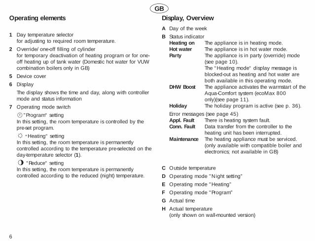
Operating elements
1 Day temperature selectorfor adjusting to required room temperature.
2 Override/one-off filling of cylinderfor temporary deactivation of heating program or for one-off heating up of tank water (Domestic hot water for VUWcombination boilers only in GB)
5 Device cover6 Display
The display shows the time and day, along with controllermode and status information
7 Operating mode switch”Program“ setting
In this setting, the room temperature is controlled by thepre-set program.
“Heating“ settingIn this setting, the room temperature is permanentlycontrolled according to the temperature pre-selected on theday-temperature selector (1).
“Reduce“ settingIn this setting, the room temperature is permanentlycontrolled according to the reduced (night) temperature.
Display, OverviewA Day of the weekB Status indicator
Heating on The appliance is in heating mode.Hot water The appliance is in hot water mode.Party The appliance is in party (override) mode
(see page 10). The “Heating mode“ display message isblocked-out as heating and hot water areboth available in this operating mode.
DHW Boost The appliance activates the warmstart of theAqua-Comfort system (ecoMax 800only)(see page 11).
Holiday The holiday program is active (see p. 36).Error messages (see page 45)Appl. Fault There is heating system fault.Conn. Fault Data transfer from the controller to the
heating unit has been interrupted.Maintenance The heating appliance must be serviced.
(only available with compatible boiler andelectronics; not available in GB)
C Outside temperatureD Operating mode "Night setting”E Operating mode "Heating”F Operating mode "Program”G Actual timeH Actual temperature
(only shown on wall-mounted version)
FR
7
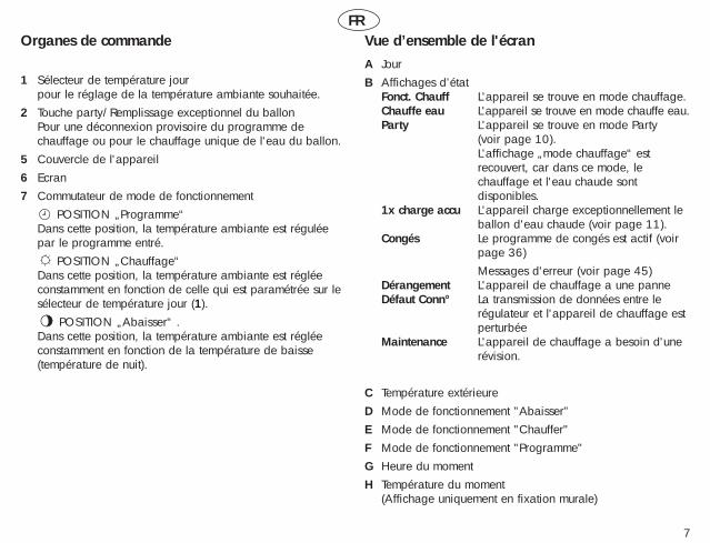
Organes de commande
1 Sélecteur de température jourpour le réglage de la température ambiante souhaitée.
2 Touche party/Remplissage exceptionnel du ballonPour une déconnexion provisoire du programme dechauffage ou pour le chauffage unique de l'eau du ballon.
5 Couvercle de l'appareil6 Ecran7 Commutateur de mode de fonctionnement
POSITION „Programme“ Dans cette position, la température ambiante est réguléepar le programme entré.
POSITION „Chauffage“ Dans cette position, la température ambiante est régléeconstamment en fonction de celle qui est paramétrée sur lesélecteur de température jour (1).
POSITION „Abaisser“ .Dans cette position, la température ambiante est régléeconstamment en fonction de la température de baisse(température de nuit).
Vue d’ensemble de l'écranA JourB Affichages d’état
Fonct. Chauff L'appareil se trouve en mode chauffage.Chauffe eau L'appareil se trouve en mode chauffe eau.Party L'appareil se trouve en mode Party
(voir page 10). L'affichage „mode chauffage“ estrecouvert, car dans ce mode, lechauffage et l'eau chaude sontdisponibles.
1x charge accu L'appareil charge exceptionnellement leballon d'eau chaude (voir page 11).
Congés Le programme de congés est actif (voirpage 36)Messages d'erreur (voir page 45)
Dérangement L'appareil de chauffage a une panneDéfaut Conn° La transmission de données entre le
régulateur et l'appareil de chauffage estperturbée
Maintenance L'appareil de chauffage a besoin d'unerévision.
C Température extérieureD Mode de fonctionnement "Abaisser"E Mode de fonctionnement "Chauffer"F Mode de fonctionnement "Programme"G Heure du momentH Température du moment
(Affichage uniquement en fixation murale)
DE GB FR
8
1 GerätebeschreibungDas Regelgerät ermöglicht die witterungs-geführte Vorlauftemperatur-Regelung einesHeizkreises. Darüber hinaus kann es dieWarmwasserbereitung und eine Zirkula-tionspumpe steuern.Der Außentemperaturfühler mißt ständigdie aktuelle Außentemperatur. Das Regel-gerät sorgt dafür, dass die eingestellteRaumtemperatur - bei voll geöffnetenThermostatventilen - erreicht wird. Hierfürmuß das Heizgerät eine bestimmte Vor-lauftemperatur bereitstellen.Sobald der Regler angeschlossen ist unddie Uhrzeit eingestellt ist, führt er einsinnvolles Heizprogramm durch. Hierfürmuß der Betriebsartenschalter (7, vordereKlappseite) in der Stellung „Programm“
stehen.
Ausführung mit DCF-EmpfängerDer im Lieferumfang enthaltene DCF-Empfänger empfängt ein Funkuhr-Zeit-signal und stellt es Ihrem Regelgerät zurVerfügung. Die Uhrzeit Ihres Reglers stelltsich automatisch ein, die Umstellung vonSommer- auf Winterzeit und umgekehrtentfällt. Eine manuelle Einstellung derUhrzeit ist nur erforderlich, wenn derFunkempfänger kein Zeitsignal erhält (vgl.Uhrzeit und Wochentag einstellen).
1 Device descriptionThe control device permits weather-activated adjustment of the flowtemperature control system. It can alsocontrol the hot water supply and acirculation pump.The outdoor-temperature sensor constantlymonitors the exterior temperature. Thecontrol system ensures that the pre-setroom temperature is achieved (with thethermostat valves fully open). The heatingsystem must be adjusted to a specific flowtemperature setting in this case.Once the controller is connected and thetimer set, it efficiently runs the heatingprogram. Note that the operating modeswitch (7, on front-panel side) should beset to the “Program“ position.
Configuration with DCF receiver (not currently available in GB)The DCF receiver supplied with the system captures the timer transmittersignal, making it available to your controlsystem. The clock-time of your controlsystem is set automatically, without anyneed to readjust from summer to wintertime or vice versa. Manual adjustment ofthe clock is only required if the receiverfails to capture a timer signal (cf. timeand day adjustment).
1 Description de l'appareilLa régulation permet de réguler latempérature départ en fonction de latempérature extérieure d’un circuit dechauffage. Elle peut commander en plusla préparation de l'eau chaude et unepompe de recyclage.La sonde de température extérieure me-sure constamment la température ex-térieure. L'appareil de réglage veille à ceque la température ambiante paramétréesoit maintenue – si les robinetsthermostatiques sont ouverts entièrement.Pour ce faire, la régulation doit présenterune certaine température départ. Dés quela régulation est raccordée et que l'heureest réglée, elle exécute un programme dechauffage approprié. Il faut pour ce faireque l'interrupteur de sélection de modede service (7, clapet frontal) se trouve enposition „Programme“ .
Version avec récepteur DCF (pas pour la France)Le récepteur DCF fourni dans l'étendue defourniture reçoit un signal radio de tempset le transmet à l'appareil de réglage.L'horloge de votre régulateur se met auto-matiquement à l'heure et le passageheure d'été heure d'hiver se fait automa-tiquement. Un réglage manuel de l'hor-loge n'est nécessaire que si le récepteurradio ne reçoit aucun signal temps (voirréglage de la date et de l'heure).
DE GB FR
9
2 BedienungDamit Ihr Heizgerät optimal arbeitet,stellen Sie den Betriebsartenschalter (7,vordere Klappseite) auf „Programm“ .
2.1 Raumtemperatur einstellenMit dem Tag-Temperaturwähler (1,vordere Klappseite) können Sie dieRaumtemperatur Ihren individuellenBedürfnissen anpassen. Position „•“entspricht einer gewünschten Raum-temperatur von ca. 20 °C. ● Raumtemperatur „Erhöhen“
Drehen Sie den Tag-Temperaturwählernach rechts.
● Raumtemperatur „Senken“Drehen Sie den Tag-Temperaturwählernach links.
Diese Temperaturregelung ist nur aktiv,wenn die Betriebsart oder eingestellt ist.
2 OperationIn order to ensure optimum operation ofyour heating appliance, set the modeswitch (7, on front-panel side) to“Program“ .
2.1 Adjusting day temperatureWith the day temperature selector(1,front folding page) you can adjust theroom temperature to individual needs.Position “•“ is set to approx. 20 °C. ● “To increase“ temperature
Turn the day temperature selector to the right.
● “To decrease“ temperatureTurn the day temperature selector to the left.
The temperature can only be adjusted ifthe operation mode of the appliance isset to heating or program .
☞ When the appliance is fitted withinthe bolier facia, no additional roomthermostat is required. The overalltemperature of the radiators can befinely adjusted to meet the heatrequirements of the property using thetemperature selector control inconjuction with the systemsthermostatic radiator valves.
2 CommandePour un fonctionnement optimal de votre appareil de chauffage (7, clapetfrontal) placez l'interrupteur de sélectionde mode sur „Programme“ .
2.1 Réglage de la température jourAvec le sélecteur de température jour (1,clapet frontal), vous pouvez adapter latempérature ambiante à vos besoinsindividuels. La Position „•“ correspond àune température ambiante de consigned’environ 20 °C. ● „Augmenter“ la température ambiante
Tournez le sélecteur de températurevers la droite.
● „Abaisser“ la température ambianteTournez le sélecteur de températurevers la gauche.
Cette régulation n’est activée que si lemode de fonctionnement Chauffer ouProgramme est sélectionné.
DE GB FR
10
2.2 LüftenStellen Sie den Betriebsartenschalter (7,vordere Klappseite) während des Lüftensauf Absenken . Damit vermeiden Sieeine unnötige Heizungseinschaltung.Nach dem Lüften stellen Sie ihn wiederzurück in Stellung Programm .
2.3 Partyfunktion einschaltenIhr Gerät ist mit einer Party-Funktionausgestattet. Diese erlaubt es Ihnen, daßdie Heiz- und Warmwasserzeiten überden nächsten Abschaltpunkt hinausfortgesetzt werden. Dies ist z. B. beieiner Feier sinnvoll, denn der Regler stelltsich am nächsten Morgen automatischzurück auf die Zeitfunktion.Diese Funktion läßt sich nur aktivieren,wenn der Betriebsartenschalter auf derPosition steht.● Drücken Sie die Partytaste (2, vordere
Klappseite).Im Display erscheint der SchriftzugParty und neben dem Symbolerscheint das Symbol .
● Mit dem Start der nächstenprogrammierten Heizzeit endet derParty-betrieb automatisch. Der Reglerarbeitet dann wieder nach denprogrammierten Zeiten.
☞ Sie können die Party-Funktion aberauch dadurch beenden, indem Siedie Partytaste (2) zweimal drücken.
2.2 Ventilation or house airingDuring airing switch the operating mode(7, front folding page) of the applianceto “Night setting“ to avoid activatingthe heating mode. After ventilating,return it to the Program setting .
2.3 Override modeYour thermostat is equipped with an override mode, which enables you tooverride the next stopping time for yourheating and hot water. It is therefore notnecessary to change your programmedstandard settings e.g. for a one-off override. This function can only beactivated if the operating switch is set tosymbol .● Press the override button (2).
The display says override, and next tosymbol the symbol appears.
● With the start of the next programmedheating period the override modeswitches off automatically. Thethermostat returns to the programmedtimings.
☞ The override mode can also be stopped by pressing the override button (2) twice.
2.2 Ventilation/aération localPendant l’aération, mettez le commuta-teur de mode de fonctionnement (7,clapet frontal)) sur „Abaisser“ . Vous éviterez ainsi un fonctionnementinutile de la chaudière.Après la ventilation, ramenez-le enposition Programme .
2.3 Touche partyVotre appareil est équipé d'une fonctionparty. Ceci vous permet de prolonger letemps de chauffage ou la période d'eauchaude au-delà du prochain point deréduction. Cette fonction est utile si vousorganisez une réception ou une soirée,car vous n'êtes pas alors obligé(e) demodifier la programmation du régulateur.Cette fonction ne peut être activée que sile commutateur de mode defonctionnement est en position .
● Appuyez sur la touche party (2).L'inscription Party apparaît à l'écranet à côté du symbole apparaît lesymbole .
● Quand la période de chauffage programmable suivante commence, lemode party s'arrête automatiquement.Le régulateur fonctionne ensuite denouveau selon les périodes programmées.
DE GB FR
11
2.4 Einmalige Ladung für WarmwasserIhr Gerät ist mit einer Funktion zureinmaligen Ladung des Speicherwassersausgestattet. Diese erlaubt es Ihnen, denWarmwasserspeicher sofort aufzuladenbzw. bei VCW-Geräten den Warmstartdes Aqua-Comfort-Systems zu aktivieren.Dies ist sinnvoll, wenn Sie z. B. eineStunde früher als gewöhnlich einegrössere Menge Warmwasser benötigen.Diese Funktion läßt sich nur aktivieren,wenn der Betriebsartenschalter auf derPosition steht.● Drücken Sie die Partytaste (2, vordere
Klappseite) zweimal.Im Display erscheint der Schriftzug1x Speicherl..
Der Regler fragt das Heizgerät ab, undschaltet die einmalige Aufladung aus,sobald das Heizgerät den Speicheraufgeladen hat.
☞ Ist der Speicher bereits Aufgeladenwird die einmalige Aufladung nach45 Minuten abgeschaltet.
☞ Sie können die einmalige Aufladungauch manuell abschalten, indem Siedie Partytaste einmal drücken. DerSchriftzug 1x Speicherl. verschwindet.
2.4 One-off filling for hot waterYour appliance is fitted with a functionthat provides for one-off filling with tankwater. This allows you to fill the hot-watertank immediately or – in the case ofcombination boilers such as the ecoMAX 800series – to activate the warm-start functionof the Aqua-Comfort system. This functionis useful when – for example – a largequantity of hot water is required an hourearlier than normal. This function canonly be activated if the operating modeswitch is in the position .● Press the “party“ override button (2,
front-side of panel) twice.The display will show the message 1x tank-fill.
The controller automatically shuts downthe one-off filling function, as soon as theboiler has satisfied this operation. ☞ If the tank is already full, the one-off
filling function is shut down after 45minutes.
☞ You can also shut down the one-offfilling function manually by pressingthe „override“ button once. The 1x tank-fill display message willnow disappear.
☞ Tank or cylinder heating is currentlynot availible in GB. This function isavailable for the warmstart of theAqua-Comfort system on the ecoMAX800 series only.
2.4 Réchauffage “prioritaire“ du ballonVotre appareil est doté de la fonction deréchauffage ˝prioritaire“ du ballon.Celle-ci vous permet de réchaufferrapidement le ballon d'eau chaude etd’activer le système de Aqua-Comfort surles appareils VUW. Cela estrecommandé quand vous avez besoind'une plus grande quantité d'eau chaudeque d'habitude une heure plus tôt parexemple.Cette fonction ne peut être activée que sil'interrupteur de sélection de mode estsur la position .● Pressez la touche Party (2, clapet
frontal) deux fois.Sur l'écran apparaît l'inscription 1x remplissage ballon
Le régulateur interroge l'appareil dechauffage et désactive le réchauffageexceptionnel dès que l'appareil dechauffage a rempli le ballon.
☞ Si le ballon est déjà chaud, leréchauffage exceptionnel s'éteintaprès 45 minutes.
☞ Vous pouvez arrêter manuellement leréchauffage exceptionnel en pressantune fois la touche Party. L'inscription˝1x charge accu“ (réchauffageballon) disparaît.
DE GB FR
12
3 Energiespartipps
☞ Stellen Sie die Raumtemperatur nur sohoch ein, daß diese für Ihr Behaglich-keitsempfinden gerade ausreicht.Jedes Grad darüber hinaus bedeuteteinen unnötigen Energieverbrauchvon etwa 6 %.
☞ Senken Sie die Raumtemperatur fürdie Zeiten Ihrer Nachtruhe undAbwesenheit ab.
☞ Öffnen Sie während der Heizperiodedas Fenster nur zum Lüften und nichtzur Temperaturregelung. Eine kurzeStoßlüftung ist wirkungsvoller undenergiesparender als langeoffenstehende Kippfenster.
☞ Stellen Sie während des Lüftens denBetriebsartenschalter (s. Geräteüber-sicht) auf „Absenken“ (Symbol ).Damit vermeiden Sie eine unnötigeHeizungseinschaltung.
☞ Lassen Sie in dem Zimmer, in demsich Ihr Regelgerät befindet, stets alleHeizkörperventile voll geöffnet.
☞ Verdecken Sie Ihr Regelgerät nichtdurch Möbel, Vorhänge oder andereGegenstände. Es muß diezirkulierende Raumluft ungehinderterfassen können.
3 Energy saving hints
☞ Set your room temperature in such away that it just reaches your comfortlevel. Every degree over and abovethat level represents an unnecessarywaste of energy of about 6%.
☞ Reduce your room temperature duringthe night and when the dwelling isnot occupied.
☞ When the heating is on openwindows for airing only - not forregulating the room temperature.Short periods of airing are moreeffective than having a small windowopen for long periods.
☞ During airing switch the operatingmode of the appliance to “Night setting” (Symbol ) to avoid activating the heating mode.
☞ In the room where the thermostat isfixed all radiator valves should be leftin the fully open position.
☞ Do not cover your thermostat with furniture, curtains or other objects. Itmust have free access to the air circulating in the room.
3 Quelques "tuyaux" pour voséconomies d'énergie☞ Ne réglez la température ambiante
que sur une valeur juste suffisantepour qu’elle soit agréable. Chaquedegré supérieur à cette limite signifieune consommation inutile d'énergied'environ 6 %.
☞ Abaissez la température ambiantepour les périodes de repos nocturneet les périodes d'absence.
☞ Pendant que vous chauffez, n'ouvrezla fenêtre que pour aérer et non pourréguler la température. Une brèveaération est plus efficace et écono-mise davantage d'énergie quel'ouverture prolongée de fenêtresentrouvertes.
☞ Pendant l'aération, mettez le commu-tateur de mode de fonctionnement(voir vue d’ensemble de l'appareil)sur "Abaisser" (symbole ). Vouséviterez ainsi un fonctionnementinutile de l’installation de chauffage.
☞ Dans la pièce dans laquelle votrerégulateur est installé, laissez toujourstous les robinets des radiateurscomplètement ouverts.
☞ Faites en sorte que votre régulateur nesoit pas recouvert par des meubles,des rideaux ou d'autres objets. Il doitpouvoir capter sans aucune entravel'air qui circule dans la pièce.
DE GB FR
13
4 Grundeinstellungen4.1 Betriebsart wählenMit dem Betriebsartenschalter (7, vordereKlappseite) können Sie die BetriebsweiseIhrer Anlage einstellen.● Stellung „Programm“
In dieser Stellungwird die Raumtemperatur vomeingegeben Programm geregelt.Während der Heizzeiten wird dieTemperatur nach der am Tag-Temperaturwähler (1) eingestelltenTemperatur geregelt, während der Ab-senkphase nach der Absenk-Temperatur.
● Stellung „Heizen“ In dieser Stellung wird die Raumtem-peratur ständig nach der Temperaturgeregelt, die am Tag-Temperatur-wähler (1) eingestellt ist. Im Displayerscheint . Die Programmierungder Schaltuhr wird nichtberücksichtigt.
● Stellung „Absenken“ .In dieser Stellung wird die Raumtem-peratur ständig nach der Absenk-Temperatur geregelt. Im Displayerscheint . Die Programmierungder Schaltuhr wird nichtberücksichtigt. Werkseitig ist dieAbsenkung auf 15 °C eingestellt.
4 Basic settings4.1 Choose the operating modeThe operating mode switch (7, front folding page) allows you to set the control for your particular needs. ● Position “Program“
The roomtemperature is controlled by theprogrammed settings. During warm-up periods, thetemperature is controlled by means ofthe day-temperature selector (1)setting, and by the reductiontemperature during the reductionphase.
● Position “Heating” The roomtemperature is constantly adjusted tothe set day temperature. The displayshows . Any programming is overridden.
● Position “Night setting” With this setting theroom temperature is constantly set atthe night temperature. The display shows .Any programming is overridden. Thefactory setting for this mode is 15 °C.
4 Les réglages de base4.1 Choisir le mode de fonctionnementAvec le commutateur de modes de fonc-tionnement (7, clapet frontal), vouspouvez adapter le mode de fonctionne-ment de votre installation à vos besoins. ● Position "Programme"
Avec ce réglage, latempérature ambiante est réglée enfonction des données programmées.Pendant les périodes de chauffage, latempérature est régulée selon latempérature paramétrée sur lesélecteur de température jour (1),pendant la phase de baisse d'après latempérature d’abaissement.
● Position "Chauffage" Avec ce réglage, la températureambiante est constamment réglée enfonction de la température définieavec le sélecteur de température jour.Le symbole apparaît à l'écran. Laprogrammation de la minuterie n'estpas prise en considération.
● Position "Abaissement"Avec ce réglage, la température de lapièce est constamment réglée en fonc-tion de la température nocturne. Lesymbole apparaît à l'écran. La pro-grammation de la minuterie n'est pasprise en considération. L'abaissementest réglé sur 15 °C par le constructeur.
43
VRC_VC2_023/0
DE Sprache GB Language
43
VRC_VC2_023/0
DE Sprache GB Language
43
VRC_VC2_023/0
DE Sprache FR Langue
14
DE GB FR
15
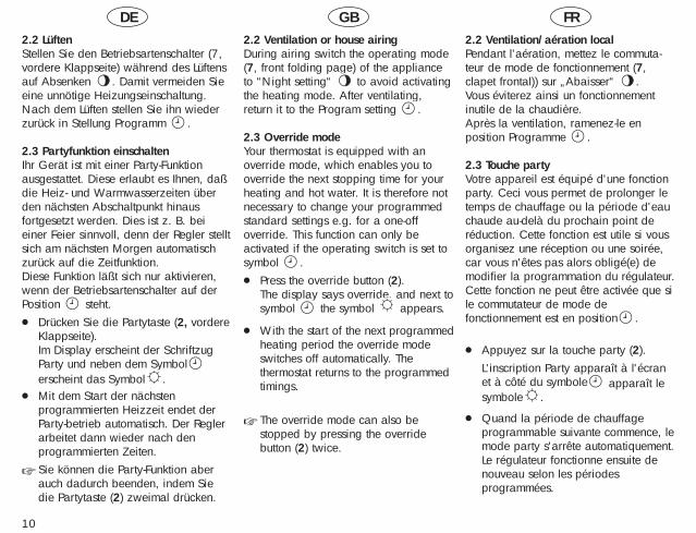
4.2 Landessprache wählen
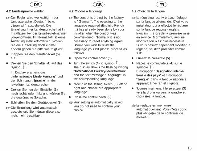
☞ Der Regler wird werkseitig in derLandessprache „Deutsch“ bzw.„Spanisch“ ausgeliefert. DieEinstellung Ihrer Landessprache hat IhrInstallateur bei der Erstinbetriebnahmevorgenommen. Im Normalfall ist keineÄnderung mehr erforderlich. WollenSie die Einstellung doch einmaländern gehen Sie bitte wie folgt vor:
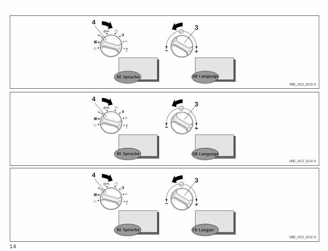
● Klappen Sie den Gerätedeckel (5)auf.
● Drehen Sie den Schalter (4) auf dasSymbol .Im Display erscheint die„internationale Länderkennung“ undder Schriftzug „Sprache“ in derjeweiligen Landessprache.
● Drehen Sie nun den Einsteller (3)nach rechts oder links und wählen Siedie gewünschte Sprache.
● Schließen Sie den Gerätedeckel (5).
☞ Die Einstellung wird automatischgespeichert. Sie müssen diese alsonicht mehr bestätigen.
4.2 Choose a language
☞ The control is pre-set by the factoryto "German”. The re-setting to the language required (English, French,…) has already been done by yourinstaller when the control was commissioned. Normally it is notnecessary to re-set anything again.Should you wish to re-set the language yourself please proceed asfollows:
● Open the control cover (5).● Turn the switch (4) to symbol .
The display shows the flashing writing“International Country-Identification”and the text message “Language“ inthe corresponding language.
● Now turn the setting switch (3) left orright and choose die appropriatelanguage.
● Close the control cover (5).
☞ Your setting is automatically saved.You do not need to confirm yourchoice.
4.2 Choix de la langue
☞ Le régulateur est livré avec réglagesur la langue allemande. C'est votreinstallateur qui a effectué le réglagesur la langue requise (anglais,français, ...) lors de la première miseen service. Normalement, aucunemodification n'est plus nécessaire. Si vous désirez cependant modifier leréglage, veuillez procéder commesuit:
● Ouvrez le couvercle (5).● Placez le commutateur (4) sur le
symbole .L'inscription "Désignation interna-tionale des pays" et l'inscription"Langue" dans la langue nationaleapparaît à l'écran et clignote.
● Tournez maintenant le sélecteur (3)vers la droite ou vers la gauche etchoisissez la langue.
☞ Le réglage est mémoriséautomatiquement. Vous n'êtes doncplus obligé(e) de le confirmer denouveau.
334
3
VRC-VC2_024/0
SoUhrzeit
SoUhrzeit
SoWochentag
MiWochentag
334
3
VRC_VC2_024/0
SuTime
SuTime
SuDay
WeDay
334
3
VRC_VC2_024/0
DiHeure
DiHeure
DiJour
MeJour
16
DE GB FR
17
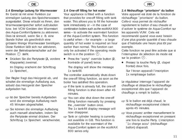
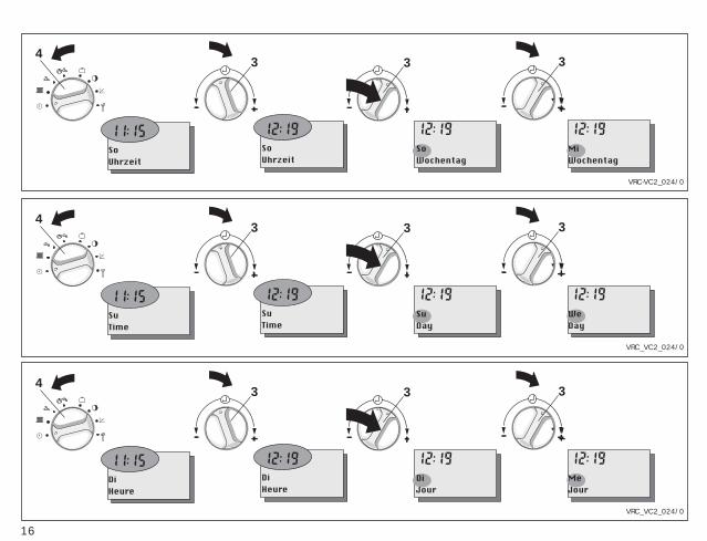
4.3 Uhrzeit und Wochentag einstellenWenn Ihr Gerät ist mit einem DCF-Empfänger ausgestattet ist, sosynchronisiert dieser die Uhrzeit mit demoffiziellen deutschen Zeitsignal, wenn derEmpfang möglich ist. Die Uhrzeit IhresRegelgerätes stellt sich automatisch ein.Das gilt auch für die Umstellung vonSommer- auf Winterzeit und umgekehrt.Müssen Sie Uhrzeit oder Wochentagjedoch einmal ändern gehen Sie bittewie folgt vor:● Klappen Sie den Gerätedeckel (5)
auf.● Drehen Sie den Schalter (4) auf das
Symbol .Im Display erscheint eine blinkendeUhrzeit und der Schriftzug „Uhrzeit“.
● Drehen Sie nun den Einsteller (3) - nach links, um die Uhrzeit zurück-
zustellen- nach rechts, um die Uhrzeit vorzu-
stellen.● Drücken Sie den Einsteller (3).
Im Display erscheint ein blinkenderWochentag mit dem Schriftzug„Wochentag“.
● Nehmen Sie die Einstellung wie beider Uhrzeit beschrieben für denWochentag vor.
☞ Uhrzeit und Datum werden auto-matisch gespeichert. Sie müssen dieneuen Werte also nicht bestätigen.
4.2 Date and time setting (The DCF receiver system is not currentlyavailable in GB)If your control is fitted with a DCFreceiver, the time for your thermostat willautomatically adjusted and synchronisedwith the German standard time - if thesignals can be received. This is also thecase for changing from summer to wintertime or vice versa. Should you, however, need to adjusteither time or date manually pleaseproceed as follows:● Open the control cover (5)● Turn switch (4) to symbol .
The display shows a flashing time andthe word “Time“ next to it.
● Now turn the knob (3)- to the left to adjust time backwards- to the right to adjust time forward
● Press the knob (3)The display shows a flashing day withthe wording “Day“.
● Follow the same steps as for time alsofor day adjusting.
☞ The new time and date are automatically saved, there is no needto confirm the new setting.
4.3 Réglage de l'heure et du jourSi votre appareil est équipé d'un récep-teur DCF (pas en France), l’heure devotre régulateur est règlé automatique-ment. Il est synchronisé avec l'heure del'horloge officielle allemande quand laréception est possible. Ceci vautégalement pour le passage de l'heured'été à l'heure d'hiver et inversement. Si vous devez modifier l'heure ou le jour,veuillez procéder comme suit:● Ouvrez le couvercle de l'appareil (5).● Placez le commutateur (4) sur le
symbole .A l'écran, l'inscription "Heure" etl'heure apparaissent ; l'heure clignote.
● Tournez maintenant le sélecteur (3)- vers la gauche, pour retarder
l'horloge- vers la droite, pour faire avancer
l'horloge.● Appuyez sur le sélecteur (3).
A l'écran, l'inscription "Jour" apparaîtet le nom d'un des jours de lasemaine clignote.
● Effectuez le réglage du jour de lasemaine comme celui de l'heure.
☞ L'heure et le jour sont mémorisésautomatiquement. Vous n'êtes doncpas obligé(e) de confirmer lesnouvelles valeurs.
°C°C 34
VRC-VC2_025/0
Min. Temp. Min. Temp.
°C°C 34
VRC-VC2_025/0
Abaissement Abaissement
18
°C°C 34
VRC-VC2_025/0
Absenktemp Absenktemp
DE GB FR
19
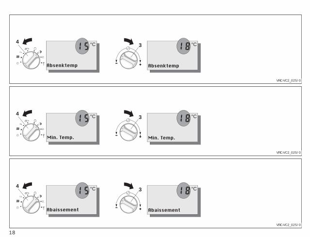
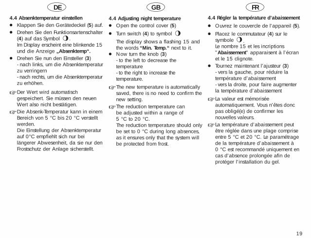
4.4 Absenktemperatur einstellen● Klappen Sie den Gerätedeckel (5) auf.● Drehen Sie den Funktionsartenschalter
(4) auf das Symbol .Im Display erscheint eine blinkende 15und die Anzeige „Absenktemp“.
● Drehen Sie nun den Einsteller (3)- nach links, um die Absenktemperaturzu verringern- nach rechts, um die Absenktemperaturzu erhöhen.
☞ Der Wert wird automatischgespeichert. Sie müssen den neuenWert also nicht bestätigen.
☞ Die Absenk-Temperatur kann in einemBereich von 5 °C bis 20 °C verstelltwerden.Die Einstellung der Absenktemperaturauf 0°C empfiehlt sich nur beilängerer Abwesenheit, da sie nur denFrostschutz der Anlage sicherstellt.
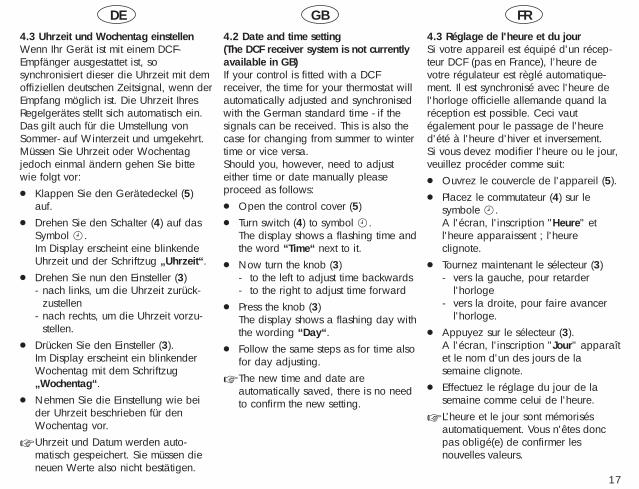
4.4 Adjusting night temperature● Open the control cover (5)● Turn switch (4) to symbol
The display shows a flashing 15 andthe words “Min. Temp.“ next to it.
● Now turn the knob (3)- to the left to decrease thetemperature- to the right to increase thetemperature.
☞ The new temperature is automaticallysaved, there is no need to confirm thenew setting.
☞ The reduction temperature can be adjusted within a range of 5 °C to 20 °C.The reduction temperature should onlybe set to 0 °C during long absences,as it ensures only that the system willbe protected from frost.
4.4 Régler la température d’abaissement● Ouvrez le couvercle de l'appareil (5).● Placez le commutateur (4) sur le
symbole .Le nombre 15 et les incriptions"Abaissement" apparaisent à l’écranet le 15 clignote.
● Tournez maintenant l’ajusteur (3)- vers la gauche, pour réduire latempérature d’abaissement- vers la droite, pour faire augmenterla température d’abaissement
☞ La valeur est mémoriséeautomatiquement. Vous n'êtes doncpas obligé(e) de confirmer lesnouvelles valeurs.
☞ La température d’abaissement peutêtre réglée dans une plage compriseentre 5 °C et 20 °C. Le paramétragede la température d’abaissement à 0 °C est recommandé uniquement encas d'absence prolongée afin deprotéger l'installation du gel.
34
VRC-VC2_026/0
Heat. Curve Heat. Curve
34
VRC-VC2_026/0
Courbe chauffe Courbe chauffe
20
34
20 15 10 5 0 – 5 – 10 – 15 – 2020
30
40
50
60
70
80
90
0.2
0.6
1.0
1.2
1.5
2.02.53.03.54.0
VRC-VC2_026/0VRC-VC2_019/0
HZ-Kurve
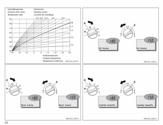
VorlauftemperaturAdvance flow temp.Température aller
HeizkurvenHeating curvesCourbes de chauffage
AußentemperaturOutside temperatureTempérature extérieure
HZ-Kurve
DE GB FR
21
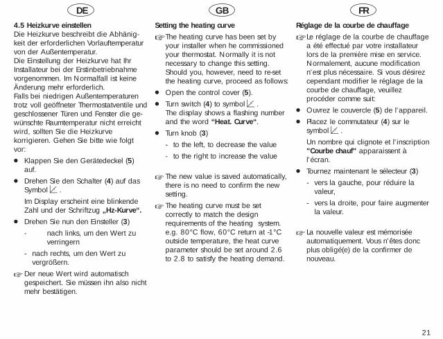
4.5 Heizkurve einstellenDie Heizkurve beschreibt die Abhänig-keit der erforderlichen Vorlauftemperaturvon der Außentemperatur. Die Einstellung der Heizkurve hat IhrInstallateur bei der Erstinbetriebnahmevorgenommen. Im Normalfall ist keineÄnderung mehr erforderlich. Falls bei niedrigen Außentemperaturentrotz voll geöffneter Thermostatventile undgeschlossener Türen und Fenster die ge-wünschte Raumtemperatur nicht erreichtwird, sollten Sie die Heizkurvekorrigieren. Gehen Sie bitte wie folgtvor:● Klappen Sie den Gerätedeckel (5)
auf.● Drehen Sie den Schalter (4) auf das
Symbol .Im Display erscheint eine blinkendeZahl und der Schriftzug „Hz-Kurve“.
● Drehen Sie nun den Einsteller (3) - nach links, um den Wert zu
verringern- nach rechts, um den Wert zu
vergrößern.
☞ Der neue Wert wird automatischgespeichert. Sie müssen ihn also nichtmehr bestätigen.
Setting the heating curve
☞ The heating curve has been set byyour installer when he commissionedyour thermostat. Normally it is notnecessary to change this setting.Should you, however, need to re-setthe heating curve, proceed as follows:
● Open the control cover (5).● Turn switch (4) to symbol .
The display shows a flashing numberand the word “Heat. Curve“.
● Turn knob (3)- to the left, to decrease the value- to the right to increase the value
☞ The new value is saved automatically,there is no need to confirm the newsetting.
☞ The heating curve must be setcorrectly to match the designrequirements of the heating system.e.g. 80°C flow, 60°C return at -1°Coutside temperature, the heat curveparameter should be set around 2.6to 2.8 to satisfy the heating demand.
Réglage de la courbe de chauffage
☞ Le réglage de la courbe de chauffagea été effectué par votre installateurlors de la première mise en service.Normalement, aucune modificationn'est plus nécessaire. Si vous désirezcependant modifier le réglage de lacourbe de chauffage, veuillez procéder comme suit:
● Ouvrez le couvercle (5) de l'appareil.● Placez le commutateur (4) sur le
symbol .Un nombre qui clignote et l'inscription"Courbe chauf" apparaissent àl'écran.
● Tournez maintenant le sélecteur (3)- vers la gauche, pour réduire la
valeur,- vers la droite, pour faire augmenter
la valeur.
☞ La nouvelle valeur est mémorisée automatiquement. Vous n'êtes doncplus obligé(e) de la confirmer de nouveau.
22
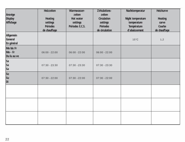
Heizzeiten Warmwasser- Zirkulations- Nachttemperatur HeizkurveAnzeige zeiten zeitenDisplay Heating Hot water Circulation Night temperature HeatingAffichage settings settings settings temperature curve
Périodes Périodes E.C.S. Périodes Température Courbede chauffage de circulation d’abaissement de chauffage
AllgemeinGeneral 15°C 1,2En général
Mo bis FrMo - Fr 06:00 - 22:00 06:00 - 22:00 06:00 - 22:00Du lu au ve
SaSa 07:30 - 23:30 07:30 - 23:30 07:30 - 23:30Sa
SoSu 07:30 - 22:00 07:30 - 22:00 07:30 - 22:00Di
DE GB FR
23
5 Zeitprogramme einstellenDas Regelgerät kann einen Heizkreissteuern. Darüber hinaus kann dieWarmwasserbereitung und dieZirkulationspumpe gesteuert werden.
5.1 Werkseitige EinstellungenWerkseitig sind sinnvolle Zeitprogrammefür die einzelnen Kreise voreingestellt.Der nebenstehenden Tabelle können Siedie werkseitigen Einstellungenentnehmen.
Sind Sie mit den Einstellungen zufriedenbrauchen Sie keine weiteren Änderungenmehr vorzunehmen.Wollen Sie die eine oder andere Einstel-lung ändern, gehen Sie bitte in dasentsprechende Kapitel der Bedienungsan-leitung.
Tipp!Bei geänderten Einstellungen ist essinnvoll, die Daten in die freien Felderder nebenstehenden Tabelle einzutragen.
5 Setting the timer programsThe system can control one heatingcircuit, the hot-water supply and thecirculation pump.
5.1 Pre-set valuesThe timer programs for the individualcircuits are factory adjusted to normaldefault settings. The opposite table showsall values which already have been pre-set. If you are happy with those settingsthere is no need for any further action.
Should you wish to change the one orother settings please look at the respective chapter in the instructions.
HINT !You might find it helpful to enter anychanged settings into the empty boxes of the table opposite.
5 Paramétrage des programmestemps
La régulation peut commander un circuitde chauffage. Elle peut en outre piloterla préparation d'eau chaude et la pompede recyclage.
5.1 Réglages du constructeurDes programmes temps recommandéspour chacun des circuits sont préréglésen usine. Le tableau ci-contre donne les réglagesdu constructeur.
Si ces réglages vous conviennent, aucunemodification n’est nécessaire.Si vous désirez faire telle ou telle modification, veuillez vous reporter auchapitre correspondant des instructionsde service.
UN "TUYAU"!En cas de modification des réglages, ilpeut être utile de noter les diversesdonnées et de les inscrire dans les casesvides du tableau ci-contre
VRC_VC_135/0
Mo-FrFenster 1
Mo-FrFenster 2
Mo-FrFenster 3
VRC_VC_135/0
Mo-FrProgramme 1
Mo-FrProgramme 2
Mo-FrProgramme 3
VRC_VC_135/0
Lu-VeFen�tre hor. 1
Lu-VeFen�tre hor. 2
Lu-VeFen�tre hor. 3
24
DE GB FR
25
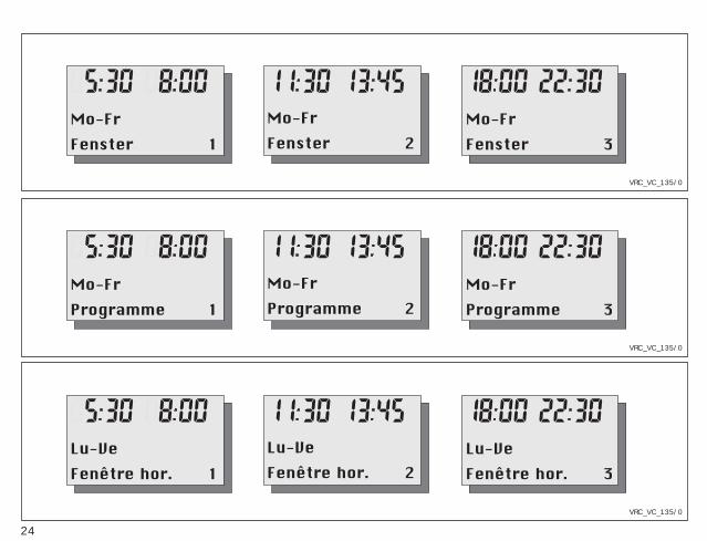
5.2 Übersicht ZeitprogrammeFür den Heizkreis, sowie für die Warm-wasserbereitung können Sie bis zu dreiHeizzeiten pro Tag programmieren, diein sogenannten Fenstern angezeigtwerden, z. B.Fenster 1:
Heizung an: 5:30Heizung aus: 8:00
Fenster 2:Heizung an: 11:30Heizung aus: 13:45
Fenster 3:Heizung an: 18:00Heizung aus: 22:30
Die Heizzeiten können Sie für die BlöckeMontag bis Sonntag (Mo-So)Montag bis Freitag (Mo-Fr)Samstag bis Sonntag (Sa-So)
oder für einzelne Tage (Mo, Di, Mi, Do,Fr, Sa, So) eingeben.
Die Ansteuerung der Zirkulationspumpeerfolgt ebenfalls über maximal dreiZeitfenster pro Tag.
5.2 OverviewYou can program the heating circuit andthe hot water supply to activate up to three times a day, using a “windows“-type system. For example,Programme 1:
Heating start: 5:30Heating stop: 8:00
Programme 2:Heating start: 11:30Heating stop: 13:45
Programme 3:Heating start: 18:00Heating stop: 22:30
These heating periods can be entered forsets of days, like
Monday to SundayMonday to FridaySaturday to Sunday
or individual days (Mo, Tu, We, Th, Fr,Sa, Su).
The activation of the circulation pump isalso carried out via a maximum of three“time windows“ per day.
☞ The secondary circulation pumpfunction requires a additional PCBaccessory for the UK market. This isavailable from Vaillant.
5.2 Présentation généralePour le circuit de chauffage ainsi quepour la préparation d'eau chaude, vouspouvez programmer jusqu'à troispériodes de chauffage par jour qui serontaffichées dans les dites fenêtres, par ex.Fenêtre 1:
Mise en marche du chauffage: 5:30Arrêt du chauffage: 8:00
Fenêtre 2:Mise en marche du chauffage: 11:30Arrêt du chauffage: 13:45
Fenêtre 3:Mise en marche du chauffage: 18:00Arrêt du chauffage: 22:30
Vous pouvez définir ces périodes dechauffage pour les blocs
Lundi à dimanche (Lu - Di)Lundi à vendredi (Lu - Ve)Samedi à dimanche (Sa - Di)
ou pour des jours isolés (Lu, Ma, Me, Je,Ve, Sa, Di).
Le pilotage de la pompe de recyclages'effectue également par trois fenêtres detemps maximum par jour.

4
VRC-VC2_027/0
Mo-FrFenster 1
4
VRC-VC2_027/0
Mo-FrProgramme 1
4
VRC-VC2_027/0
Lu-VeFen�tre hor. 1
26
DE GB FR
27
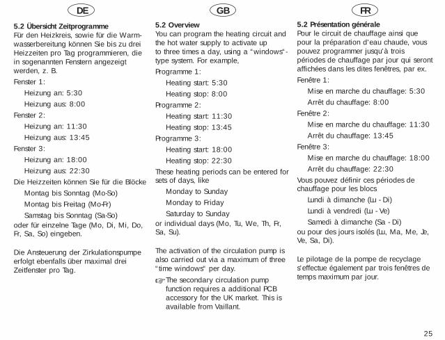
5.3 Heizzeiten einstellen Das Einstellen der Heizzeiten läßt sicham besten anhand eines Beispielserklären. Spielen Sie das Beispiel einmaldurch (es dauert keine zehn Minuten)und Sie werden sehen wie einfach dieseProgrammierung ist.Die Heizung soll für den Heizkreis zufolgenden Zeiten in Betrieb gehen:
von Montags bis Freitags:Heizung an: 5:30Heizung aus: 9:00Heizung an: 17:00Heizung aus: 22:00
von Samstags bis Sonntags:Heizung an: 8:00Heizung aus: 23:00
Gehen Sie bitte folgendermaßen vor:● Klappen Sie den Gerätedeckel (5)
auf.● Drehen Sie den Schalter (4) auf
für den Heizkreis
Im Display erscheint blinkend„Fenster 1“ mit den vorgegebenenWochentagen, z. B. Montag bisFreitag.
5.3 Programming heating periodsThe programming of heating periods isbest explained with an example. Try theexample setting (it won’t take more than10 minutes) and you will see how easythe programming is.Heating should come on during the following times:Monday – Friday
Heating on: 05.30Heating off: 09.00Heating on: 17.00Heating off: 22.00
Saturday - SundayHeating on: 08.00Heating off: 23.00
Proceed as follows:● Open the control cover (5).● Turn switch (4) to symbol
for the heating circuit.
The display shows a flashing
“Programme 1“ with the chosen days,
e.g. Monday - Friday.
5.3 Programmation des périodes de chauffage
Le mieux est d'expliquer la program-mation des périodes de chauffage àl’aide d’un exemple. Procédez une seulefois en suivant la description (cela vousdemandera moins de dix minutes) et vousconstaterez vous-même la simplicité decette programmation.Le chauffage doit être activé pendant lespériodes suivantes:du lundi au vendredi:
Mise en marche du chauffage: 5:30Arrêt du chauffage: 9:00Mise en marche du chauffage: 17:00Arrêt du chauffage: 22:00
du samedi au dimanche:Mise en marche du chauffage: 8:00Arrêt du chauffage: 23:00
Procédez comme suit:● Ouvrez le couvercle de l'appareil (5).● Tournez le commutateur (4) sur le
symbole:
pour le circuit de chauffageA l'écran, l'inscription "Fenêtrehor. 1" apparaît en clignotant avecles jours de la semaine prédéfinis,par exemple lundi à vendredi.
33 3 3
VRC-VC2_015/0
Mo-FrOn time 1
Mo-FrOn time 1
Mo-FrOff time 1
Mo-FrOff time 1
33 3 3
VRC-VC2_015/0
Lu-VeD�but 1
Lu-VeD�but 1
Lu-VeFin 1
Lu-VeFin 1
33 3 3
VRC-VC2_015/0
Mo-FrBeginn 1
Mo-FrBeginn 1
Mo-FrEnde 1
Mo-FrEnde 1
28
DE GB FR
29
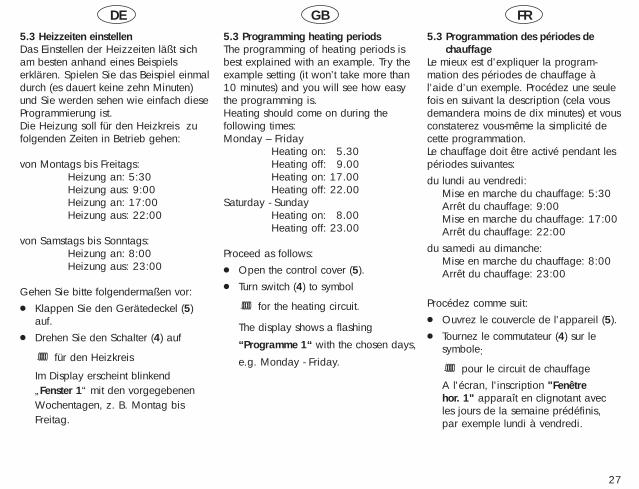
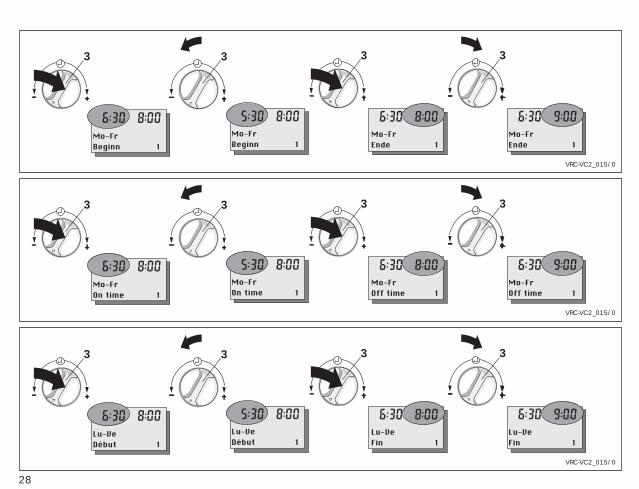
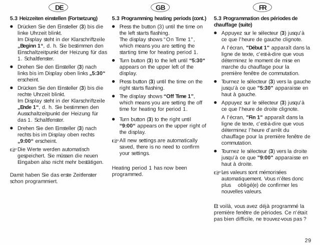
5.3 Heizzeiten einstellen (Fortsetzung)● Drücken Sie den Einsteller (3) bis die
linke Uhrzeit blinkt.Im Display steht in der Klarschriftzeile„Beginn 1“, d. h. Sie bestimmen denEinschaltzeitpunkt der Heizung für das1. Schaltfenster.
● Drehen Sie den Einsteller (3) nachlinks bis im Display oben links „5:30“erscheint.
● Drücken Sie den Einsteller (3) bis dierechte Uhrzeit blinkt.Im Display steht in der Klarschriftzeile„Ende 1“, d. h. Sie bestimmen denAusschaltzeitpunkt der Heizung fürdas 1. Schaltfenster.
● Drehen Sie den Einsteller (3) nachrechts bis im Display oben rechts„9:00“ erscheint.
☞ Die Werte werden automatischgespeichert. Sie müssen die neuenEingaben also nicht mehr bestätigen.
Damit haben Sie das erste Zeitfensterschon programmiert.
5.3 Programming heating periods (cont.)● Press the button (3) until the time on
the left starts flashing.The display shows “On Time 1”,which means you are setting the starting time for heating period 1.
● Turn button (3) to the left until “5:30“appears on the upper left of thedisplay.
● Press button (3) until the time on theright starts flashing.
● The display shows “Off Time 1”,which means you are setting the offtime for heating for period 1.
● Turn button (3) to the right until“9:00“ appears on the upper right ofthe display.
☞ All new settings are automaticallysaved, there is no need to confirmyour settings.
Heating period 1 has now been programmed.
5.3 Programmation des périodes de chauffage (suite)● Appuyez sur le sélecteur (3) jusqu'à
ce que l'heure de gauche clignote.A l'écran, "Début 1" apparaît dans laligne de texte, c'est-à-dire que vousdéterminez le moment de mise enmarche du chauffage pour la première fenêtre de commutation.
● Tournez le sélecteur (3) vers la gauchejusqu'à ce que "5:30" apparaisse enhaut à gauche.
● Appuyez sur le sélecteur (3) jusqu'àce que l'heure de droite clignote.A l'écran, "Fin 1" apparaît dans laligne de texte, c'est-à-dire que vousdéterminez l'heure d'arrêt du chauffage pour la première fenêtre decommutation.
● Tournez le sélecteur (3) vers la droitejusqu'à ce que "9:00" apparaisse enhaut à droite.
☞ Les valeurs sont mémoriséesautomatiquement. Vous n'êtes doncplus obligé(e) de confirmer lesnouvelles valeurs.
Et voilà, vous avez déjà programmé lapremière fenêtre de périodes. Ce n'étaitpas bien difficile, ne trouvez-vous pas ?
3 3 3 3
VRC-VC2_016/0
Lu-VeFen�tre hor. 1
Lu-VeFen�tre hor 2
Lu-VeD�but 2
Lu-VeD�but 2
3 3 3 3
VRC-VC2_016/0
Mo-FrProgramme 1
Mo-FrProgramme 2
Mo-FrOn time 2
Mo-FrOn time 2
3 3 3 3
VRC-VC2_016/0
Mo-FrFenster 1
Mo-FrFenster 2
Mo-FrBeginn 2
Mo-FrBeginn 2
30

DE GB FR
31
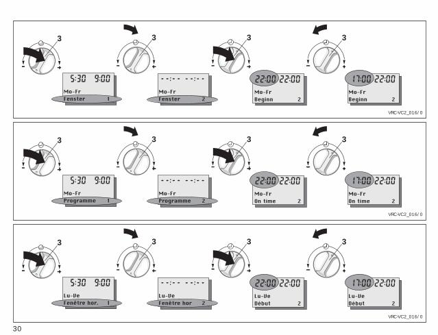
5.3 Heizzeiten einstellen (Fortsetzung)Nun soll das zweite Zeitfensterprogrammiert werden:● Drücken Sie den Einsteller (3) bis die
Zeile „Fenster 1“ im Display blinkt.● Drehen Sie den Einsteller (3) nach
rechts (vor) bis die Zeile „Fenster 2“im Display erscheint.Im Display erscheint „- -:- -“, wennEin- und Ausschaltzeitpunkt gleichsind. Andernfalls erscheinen dieeingestellten Uhrzeiten im Display.
● Drücken Sie den Einsteller (3) bis dielinke Uhrzeit blinkt.Jetzt erscheinen immer die Zeiten imDisplay (auch wenn Ein- und Aus-schaltzeitpunkt gleich sind).Im Display steht in der Klarschriftzeile„Beginn 2“, d. h. Sie bestimmen denEinschaltzeitpunkt der Heizung inFenster 2.
● Stellen Sie die Uhrzeiten für Fenster 2genauso ein wie für Fenster 1beschrieben.
Damit ist auch das zweite Zeitfensterprogrammiert, d. h. für unser Beispiel,die Einstellzeiten für Montag bis Freitagsind eingegeben.
5.3 Programming heating periods (cont.)Now we program the second window:● Press knob (3) until the display
“Programme 1” is flashing.● Turn the knob (3) to the right until the
display shows “Programme 2”.The display will show „- -:- -“, if theset on and off times are the same. Inall other cases the normal time settings will be shown.
● Press the knob (3) until the heating ontime (upper left of the display) startsflashing.From now on you will always see theactual programmed time displayed(even if starting and stopping timesare the same).The display shows “On Time 2”,which means you are setting the star-ting time for heating programme 2.
● Adjust the timer setting for programme2 in the same way as described forwindow 1.
Thus, the second window is alsoprogrammed, i.e. (for our example) thesetting times for Monday to Friday areentered.
5.3 Programmation des périodes de chauffage (suite)Il faut maintenant programmer la deuxième fenêtre de périodes:● Appuyez sur le sélecteur (3) jusqu'à
ce que la ligne "Fenêtre hor. 1"clignote à l’écran.
● Tournez le sélecteur (3) vers la droite(avance) jusqu'à ce que la ligne"Fenêtre hor. 2" apparaisse à l'écran."--:--" apparaît à l'écran quand l'heure de mise en marche et d'arrêtsont identiques. Sinon, les heures normales apparaissent à l'écran.
● Appuyez sur le sélecteur (3) jusqu'àce que l'heure de gauche clignote.A partir de ce point, les heures apparaissent toujours à l'écran (mêmesi l'heure de mise en marche etd'arrêt sont identiques).A l'écran, "Début 2" apparaît dans laligne de texte, c'est-à-dire que vousdéterminez l'heure de mise en marchedu chauffage dans la fenêtre 2.
● Paramétrez les heures pour la fenêtre2 tel que décrit pour la fenêtre 1.
Ainsi, la seconde fenêtre temps estégalement programmée, c'est-à-dire pournotre exemple, les temps de réglage dulundi au vendredi sont entrés.
3 3 3 3
VRC-VC2_017/0
Mo-FrFenster 1
Mo-FrWochentag 1
Sa-SoWochentag 1
Sa-SoBeginn 1
3 3 3 3
VRC-VC2_017/0
Mo-FrProgramme 1
Mo-FrDay 1
Sa-SuDay 1
Sa-SuOn time 1
3 3 3 3
VRC-VC2_017/0
Lu-VeFen�tre 1
Lu-VeJour 1
Sa-DiJour 1
Sa-DiD�but 1
32
DE GB FR
33
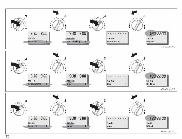
5.3 Heizzeiten einstellen (Fortsetzung)Jetzt fehlen nur noch die Zeiten für dasWochenende:● Drücken Sie den Einsteller (3) bis die
Zeile „Fenster 2“ im Display blinkt.● Drehen Sie den Einsteller (3) nach
links bis die Zeile „Fenster 1“ imDisplay erscheint.
● Drücken Sie den Einsteller (3) bis dieWochentage „Mo-Fr“ im Displayblinken.Im Display steht in der Klarschriftzeile„Wochentag 1“.
● Drehen Sie den Einsteller (3) nachrechts bis die Wochentage „Sa-So“im Display blinken.
● Drücken Sie den Einsteller (3) bis dielinke Uhrzeit blinkt.Im Display steht in der Klarschriftzeile„Beginn 1“, d. h. Sie bestimmen denEinschaltzeitpunkt der Heizung inFenster 1 für das Wochenende.
● Stellen Sie die Heizzeiten ein wie fürdas erste Fenster von Mo-Frbeschrieben.
Damit ist die Programmierung für dasBeispiel komplett durchgeführt und Siekönnen nun die Heizzyklen Ihrenindividuellen Bedürfnissen anpassen.
5.3 Programming heating periods (cont.)Now we have to set the timings forweekends:● Press knob (3) again until the display
shows “Programme 2” are flashing inthe display.
● Turn the knob (3) to the left until thedisplay shows “Programme 1”.
● Press knob (3) again until days “Mo-Fr“ are flashing in the display.The display now shows “Day 1” inclear writing.
● Turn knob (3) to the right until thedays “Sa-Su“ are flashing in the display.
● Press button (3) until the time displayon the left of the display starts flashing.The display shows “On Time 1”,which means you are setting thestarting time for heating programme 1on weekends.
● Set the heating times as described forthe first programme from Mo-Fr.
That concludes the programming of ourexample settings. You can now adjustyour heating cycles to your personalpreferences.
5.3 Programmation des périodes de chauffage (suite)Seules manquent maintenant les heuresde la fin de semaine:● Appuyez sur le sélecteur (3) jusqu’à
ce que la ligne "Fenêtre hor. 2"clignote à l’écran.
● Tournez le sélecteur (3) vers la gauchejusqu'à ce que la ligne "Fenêtre hor.1" apparaisse à l'écran.
● Appuyez sur le sélecteur (3) jusqu'àce que les jours "Lu-Ve" clignotent àl'écran.A l'écran, "Fonct° jour 1" apparaîtdans la ligne de texte.
● Tournez le sélecteur (3) vers la droitejusqu'à ce que les jours "Sa-Di"clignotent à l'écran.
● Appuyez sur le sélecteur (3) jusqu'àce que l'heure de gauche clignote.A l'écran, "Début 1" apparaît dans laligne de texte, c'est-à-dire que vousdéterminez l'heure d'arrêt du chauffage dans la fenêtre 1 pour lafin de semaine.
● Paramétrez les temps de chauffage telque décrit pour la première fenêtre delundi à vendredi.
L’exemple de programmation est ainsiachevé et vous pouvez adaptermaintenant les cycles de chauffage à vosbesoins personnels.
34
5.4 Warmwasserzeiten einstellen
Mit Ihrem Regelgerät können Sie bis zudrei Warmwasserzeiten pro Tagprogrammieren. Der Schalter 4 unterdem Gerätedeckel muß auf Symbolstehen. Die programmmierten Zeitenwerden in sogenannten Fensternangezeigt (siehe Seite 24).
Da die Programmierung analog zu denHeizzeiten durchzuführen ist, fahren Siebitte fort, wie auf den Seiten 26 bis 33beschrieben.
5.4 Set hot water supply periods(For GB VUW combination boilers withwarmstart only)Your thermostat allows you to programup to 3 periods of time per day for thesupply of hot water. Switch 4 underneaththe control cover has to be set tosymbol .The programmed timings are displayedin periods (see page 24).
The programming for hot water is performed in exactly the same manner as programming heating times, which isdescribed on pages 26 to 33.
☞ in GB you can only programme thewarm-start of the Aqua-Comfortsystem of Vaillant combination boilers(e.g. ecoMAX 800 series).
5.4 Réglage des périodes d’eau chaudeVotre régulation vous permet deprogrammer jusqu'à trois périodes d'eauchaude par jour. Le commutateur 4 situéau-dessous du couvercle de l'appareildoit être placé sur le symbole . Lespériodes programmées sont affichéesdans les fenêtres (voir page 24).
Comme la programmation doit être réalisée de façon analogue à celle despériodes de chauffage, veuillez continueren suivant les instructions des pages 26à 33.
DE GB FR
DE GB FR
35
5.5 Zirkulationszeiten einstellenAls Zubehör zum Gerät ist eine Zirkula-tionspumpe erhältlich. Einige Heizgerätebenötigen zusätzlich ein Zubehörmodulzur Steuerung der Zirkulationspumpe,bitte lesen Sie in der Installationsanlei-tung Ihres Heizgerätes nach. Ist Ihre Anlage mit einerZirkulationsleitung ausgestattet, könnenSie mit Ihrem Regelgerät bis zu dreiZirkulationszeiten pro Tagprogrammieren. Der Schalter 4 unter dem Gerätedeckelmuß auf Symbol stehen. Die programmierten Zeiten werden insogenannten Fenstern angezeigt (sieheSeite 24).
Da die Programmierung analog zu denHeizzeiten durchzuführen ist, fahren Siebitte fort, wie auf den Seiten 26 bis 33beschrieben.
5.5 Set circulating periodsA circulation pump is available as anaccessory to your appliance. Thesecondary circulation pump functionrequires a additional PCB accessory forthe GB market. This is available fromVaillant.Should your appliance alreadyhave a circulation pump you canprogram with your thermostat up to 3operation periods per day. Switch 4 underneath the appliance coverhas to be set to symbol .The programmed timings are displayedin periods (see page 24).
The programming is performed in exactlythe same manner as programming heating times, which is described onpages 26 to 33.
5.5 Réglage des périodes de recyclageUne pompe de recyclage est disponiblecomme accessoire. Quelques chaudièresnécessitent un accessoire supplémentairepour commander la pompe derecyclage, veuillez vous respecter lanotice d’installation de votre chaudière.Si votre installation est équipée d'uneboucle de recyclage, vous pouvez programmer jusqu'à troispériodes de recyclage par jour. Le commutateur 4 situé au-dessous ducouvercle de l'appareil doit être placé sur le symbole . Les périodesprogrammées sont affichées dans lesfenêtres (voir page 24).
Comme la programmation doit être réalisée de façon analogue à celle des périodes de chauffage, veuillez continuer en suivant les instructions despages 26 à 33.
3 3 34
VRC-VC2_028/0
DiD�but cong�s
jeD�but cong�s
JeFin cong�s
JeFin cong�s
3 3 34
VRC-VC2_028/0
SuHoliday Start
ThHoliday Start
ThNo. of days
ThNo. of days
3 3 34
VRC-VC2_028/0
SoUrlaub Start
DoUrlaub Start
DoUrlaubstage
DoUrlaubstage
36
DE GB FR
37
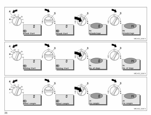
5.7 FerienprogrammIhr Gerät hat ein Ferienprogramm, mit demSie Heizung, Warmwasser und Zirkulationfür die Dauer Ihres Urlaubs abschalten oderabsenken können. Diese Funktion kann 6Tage vor Urlaubsbeginn gestartet werden.Bitte beachten Sie, dass das Ferienpro-gramm nur wirksam ist, wenn der Betriebs-artenschalter (7, Klappseite) auf Stellung steht.● Klappen Sie den Gerätedeckel (5) auf.● Drehen Sie den Schalter (4) auf das
Symbol .Im Display erscheint ein blinkenderWochentag und der Schriftzug „UrlaubStart“.☞ Sie können dies frühestens 6 Tage
vor Urlaubsantritt eingeben.● Drehen Sie nun den Einsteller (3) nach
links oder rechts, um den gewünschtenWochentag für den Beginn des Ferien-programms einzustellen.
● Drücken Sie den Einsteller (3).Im Display erscheint eine blinkende Zahlmit dem Schriftzug „Urlaubstage“.☞ Sie können maximal 99 Urlaubs-
tage eingeben.☞ Drehen auf Null beendet das
Ferienprogramm.● Nehmen Sie die Einstellung durch
Drehen des Einstellers (3) nach linksoder rechts vor.
☞ Urlaubsstart und Urlaubstage werdenautomatisch gespeichert. Sie müssen dieneuen Werte also nicht bestätigen.
5.7 Holiday programYour controller is equipped with a holi-day program which allows you to turn offheating, hot water and the circulationpump for the duration of your holiday.The programming can be done up to 6days in advance. Please note, that theholiday program can only be activated if the operating switch (7, front foldingpage) is set to positiong .● Open the control cover (5).● Turn switch (4) to symbol .
Now the display shows a flashingday of the week with the wording“Holiday start“.☞ You can enter the holiday start
day the earliest 6 days in advance.
● Turn the knob (3)- to the left or to the right to set
your holiday start● Press knob (3).
The display shows a flashing numberand the word “No. of days“, whichindicates the number of days that thesystem will be turned off.☞ You can enter a maximum of 99
days.☞ Turning to zero stops the holiday
program.● Set the number of days in exactly the
same way as described above.☞ Holiday start and the number of days
are saved automatically, there is noneed to confirm the new setting.
5.7 Programme de congésVotre appareil a un programme de congésavec lequel vous pouvez désactiver ou baisser le chauffage, l'eau chaude et lerecyclage pour la durée de vos vacances.Vous pouvez mettre en oeuvre le programmede votre période de congés 6 jours avant ledébut de celle-ci. Veuillez tenir compte dufait que le programme de congés n'estactivé que si le commutateur de modes defonctionnement (7,clapet) est en position ● Ouvrez le couvercle de l'appareil (5).● Placez le commutateur (4) sur le symbole
. Un jour de la semaine apparaît àl’écran avec l'inscription "Début congés"et clignote.☞ Vous pouvez entrer les données
correspondantes au plus tôt 6 joursavant le début des congés.
● Tournez maintenant le sélecteur (3)vers la gauche ou vers la droite poureffectuer le réglage sur le jour de lasemaine que vous avez choisi pour ledébut du programme de congés.
● Appuyez sur le sélecteur (3). Un nombreapparaît à l'écran avec l'inscription „Fincongés“ et clignote.☞ Vous pouvez entrer au maximum
99 jours de congés.☞ En effectuant le réglage sur zéro,
vous mettez fin au programme de congés.
● Effectuez le réglage en tournant le sélec-teur (3) vers la gauche ou vers la droite.
☞ Début congés et jours de congés sontmémorisés automatiquement. Vous n'êtes donc pas obligé(e) de confirmerles nouvelles valeurs.
38
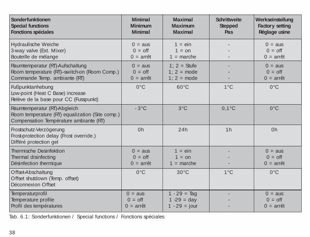
Sonderfunktionen Minimal Maximal Schrittweite WerkseinstellungSpecial functions Minimum Maximum Stepped Factory settingFonctions spéciales Minimal Maximal Pas Réglage usine
Hydraulische Weiche 0 = aus 1 = ein - 0 = aus3-way valve (Ext. Mixer) 0 = off 1 = on - 0 = offBouteille de mélange 0 = arrêt 1 = marche - 0 = arrêt
Raumtemperatur (RT)-Aufschaltung 0 = aus 1; 2 = Stufe - 0 = ausRoom temperature (RT)–switch-on (Room Comp.) 0 = off 1; 2 = mode - 0 = offCommande Temp. ambiante (RT) 0 = arrêt 1; 2 = mode - 0 = arrêt
Fußpunktanhebung 0°C 60°C 1°C 0°CLow-point (Heat C Base) increaseRelève de la base pour CC (Fusspunkt)
Raumtemperatur (RT)-Abgleich - 3°C 3°C 0,1°C 0°CRoom temperature (RT) equalization (Site comp.)Compensation Température ambiante (RT)
Frostschutz-Verzögerung 0h 24h 1h 0hFrost-protection delay (Frost override.)Différé protection gel
Thermische Desinfektion 0 = aus 1 = ein - 0 = ausThermal disinfecting 0 = off 1 = on - 0 = offDésinfection thermique 0 = arrêt 1 = marche - 0 = arrêt
Offset-Abschaltung 0°C 30°C 1°C 0°COffset shutdown (Temp. offset)Déconnexion Offset
Temperaturprofil 0 = aus 1 - 29 = Tag - 0 = ausTemperature profile 0 = off 1 -29 = day - 0 = offProfil des températures 0 = arrêt 1 - 29 = jour - 0 = arrêt
Tab. 6.1: Sonderfunktionen / Special functions / Fonctions spéciales
DE GB FR
39
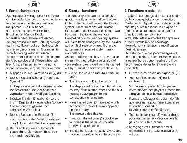
6 SonderfunktionenDas Regelgerät verfügt über eine Reihevon Sonderfunktionen, die es ermöglichenden Regler an die Heizungsanlageanzupassen. Die Funktionen,Einstellbereiche und werkseitigenEinstellungen können Sie dernebenstehenden Tabelle entnehmen. Die Anpassung auf Ihre Heizungsanlagehat Ihr Installateur bei der Erstinbetrieb-nahme vorgenommen. Im Normalfall istkeine Änderung mehr erforderlich. Da diese Einstellungen einen Einfluss aufdie Arbeitsweise und WirtschaftlichkeitIhrer Anlage haben, sollten sie nur voneinem Fachmann vorgenommen werden.● Klappen Sie den Gerätedeckel (5) auf.● Drehen Sie den Schalter (4) auf das
Symbol .Im Display erscheint die internationaleLänderkennung und der Schriftzug„Sprache“ in der jeweiligen Sprache.
● Drücken Sie den Einsteller (3) so oft,bis im Display die gewünschte Sonder-funktion angezeigt wird. Dereingestellte Wert blinkt.
● Drehen Sie nun den Einsteller (3) nach rechts um den Wert zu erhöhenoder links um den Wert zu verringern
☞ Die Einstellung wird automatischgespeichert. Sie müssen diese alsonicht mehr bestätigen.
6 Special functionsThe control system can run a series ofspecial functions, which allow the con-troller to be compatible with the heatingsystem. These functions, adjustmentranges and factory-adjusted settings canbe seen in the table shown here.Compatibility with your heating systemwill have been configured by the installerat the initial start-up phase. No furtheradjustment is required under normalcircumstances.As these adjustments have a bearing onthe running and efficient operation ofyour system, they should only be carriedout by a qualified servicing technician.● Swivel the cover panel (5) of the unit
open.● Turn the switch (4) to the symbol .
The display will show the internationalcountry-identification letter and the textmessage „Language“ in thecorresponding language.
● Press the adjuster (3) repeatedly untilthe desired special function appearson the display. The pre-set value flashes.
● Now turn the adjuster (3) clockwise to increase the value, or counter-clockwise to reduce it.
☞ The setting is automatically saved, andneed not therefore be confirmed again.
6 Fonctions spécialesL'appareil de réglage dispose d'une sériede fonctions spéciales qui permettentd'adapter la régulation à l'installation dechauffage. Les fonctions, les plages deréglage et les réglages usine figurentdans les tableaux ci-contre. Votre installateur a effectué l'adaptation à votre installation de chauffage.Normalement plus aucune modificationn'est nécessaire. Etant donné que ces paramétrages ontune répercussion sur le fonctionnement etla rentabilité de votre installation, il estrecommandé de les faire faire par unspécialiste.● Ouvrez le couvercle de l'appareil (5).● Tournez l'interrupteur (4) sur le
symbole .Sur l'écran apparaît la désignationinternationale des pays et l'inscription„langue“ dans la langue respective.
● Pressez le sélecteur (3) autant de foisque nécessaire pour faire apparaîtrela fonction souhaitée. La valeur paramétrée clignote.
● Tournez le sélecteur (3) vers la droitepour augmenter la valeur ou vers lagauche pour la diminuer
☞ Le réglage est automatiquementmémorisé. Il n'est pas nécessaire devalider.
DE GB FR
40
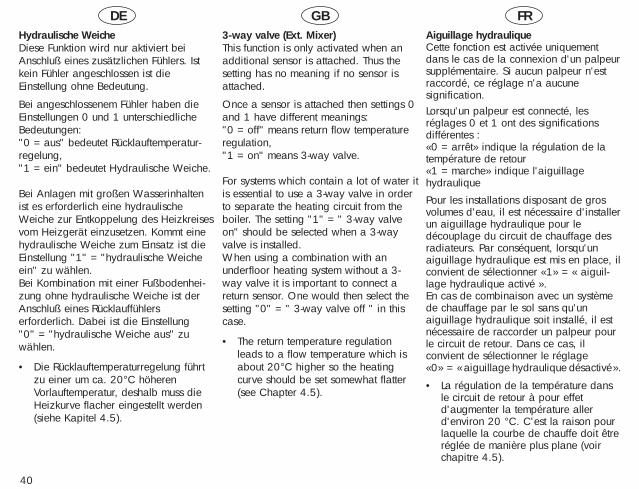
Hydraulische WeicheDiese Funktion wird nur aktiviert beiAnschluß eines zusätzlichen Fühlers. Istkein Fühler angeschlossen ist dieEinstellung ohne Bedeutung.
Bei angeschlossenem Fühler haben dieEinstellungen 0 und 1 unterschiedlicheBedeutungen: "0 = aus" bedeutet Rücklauftemperatur-regelung, "1 = ein" bedeutet Hydraulische Weiche.
Bei Anlagen mit großen Wasserinhaltenist es erforderlich eine hydraulischeWeiche zur Entkoppelung des Heizkreisesvom Heizgerät einzusetzen. Kommt einehydraulische Weiche zum Einsatz ist dieEinstellung "1" = "hydraulische Weicheein" zu wählen.Bei Kombination mit einer Fußbodenhei-zung ohne hydraulische Weiche ist derAnschluß eines Rücklauffühlerserforderlich. Dabei ist die Einstellung "0" = "hydraulische Weiche aus" zuwählen.
• Die Rücklauftemperaturregelung führtzu einer um ca. 20°C höherenVorlauftemperatur, deshalb muss dieHeizkurve flacher eingestellt werden(siehe Kapitel 4.5).
3-way valve (Ext. Mixer)This function is only activated when anadditional sensor is attached. Thus thesetting has no meaning if no sensor isattached.
Once a sensor is attached then settings 0and 1 have different meanings: "0 = off" means return flow temperatureregulation, "1 = on" means 3-way valve.
For systems which contain a lot of water itis essential to use a 3-way valve in orderto separate the heating circuit from theboiler. The setting "1" = " 3-way valveon" should be selected when a 3-wayvalve is installed.When using a combination with anunderfloor heating system without a 3-way valve it is important to connect areturn sensor. One would then select thesetting "0" = " 3-way valve off " in thiscase.
• The return temperature regulationleads to a flow temperature which isabout 20°C higher so the heatingcurve should be set somewhat flatter(see Chapter 4.5).
Aiguillage hydrauliqueCette fonction est activée uniquementdans le cas de la connexion d'un palpeursupplémentaire. Si aucun palpeur n'estraccordé, ce réglage n'a aucunesignification.Lorsqu'un palpeur est connecté, lesréglages 0 et 1 ont des significationsdifférentes :«0 = arrêt» indique la régulation de latempérature de retour«1 = marche» indique l'aiguillagehydraulique
Pour les installations disposant de grosvolumes d'eau, il est nécessaire d'installerun aiguillage hydraulique pour ledécouplage du circuit de chauffage desradiateurs. Par conséquent, lorsqu'unaiguillage hydraulique est mis en place, ilconvient de sélectionner «1» = « aiguil-lage hydraulique activé ».En cas de combinaison avec un systèmede chauffage par le sol sans qu'unaiguillage hydraulique soit installé, il estnécessaire de raccorder un palpeur pourle circuit de retour. Dans ce cas, ilconvient de sélectionner le réglage «0» = «aiguillage hydraulique désactivé».
• La régulation de la température dansle circuit de retour à pour effetd'augmenter la température allerd'environ 20 °C. C'est la raison pourlaquelle la courbe de chauffe doit êtreréglée de manière plus plane (voirchapitre 4.5).
DE GB FR
41
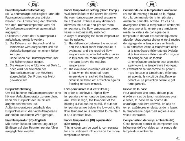
Raumtemperaturaufschaltung Bei Wandmontage des Reglers kann dieRaumtemperatursteuerung aktiviertwerden. Bei Abweichung der Raumist-von der Raumsolltemperatur wird derVorlauftemperatursollwert automatischangepaßt.Es können 2 Arten der Raumtemperatur-aufschaltung gewählt werden:1. Die Differenz von Raumsoll- und Ist-
Temperatur wird ausgewertet und dieVorlaufsolltemperatur mit einem Faktorkorrigiert.Dabei kann die Raumtemperatur überdie Solltemperatur steigen.
2. Die Auswertung erfolgt wie bei Stufe 1,doch wird bei erreichen derRaumsolltemperatur der Heizkreisabgeschaltet. Der Frostschutz bleibtgewährleistet.
FußpunktanhebungUm bei höheren Außentemperaturen einehöhere Vorlauftemperatur zu erreichen,kann der Fußpunkt der Heizkurveangehoben werden. BeiAußentemperaturen unterhalb desFußpunktes wird die Vorlauftemperaturauf einem konstanten Wert geregelt.
Raumtemperatur (RT)-AbgleichMit dieser Funktion können ungünstigeEinflüsse auf den Raumtemperaturfühlerausgeglichen werden.
Commande de la température ambiante En cas de montage mural de la régula-tion, la commande de la températureambiante peut être activée. En cas dedivergence entre la température ambiantede consigne et la température ambianteréelle, la valeur de consigne de latempérature départ est automatiquementajustée. Vous pouvez choisir entre 2 modesde réglage de la température ambiante :1. La différence entre la température réelle
et la température théorique est évaluéeet la température théorique d’amorçageest corrigée par un facteur.La température ambiante peut alors êtresupérieure à la température théorique.
2. L’évaluation se fait comme au point 1mais, lorsque la température théoriqueest atteinte, le circuit de chauffage sedésactive. La protection contre le gelreste garantie.
Relève de la basePour atteindre une temp. départ plusélevée en cas de temp. extérieures plusélevées, la base de la courbe dechauffage peut être relevée. En cas detemp. extérieures en-dessous de la base,la température départ est réglée à unevaleur constante.
Compensation de temp. ambiante (RT)Cette fonction permet de compenser desinfluences défavorables sur la sonde detempérature ambiante.
Room temperature setting (Room Comp.)Wall-installation of the controller allowsthe room-temperature control system to be activated. If there is any differencebetween the actual and pre-set roomtemperature, the flow temperature targetvalue is automatically matched.2 ways of changing the room temperaturecan be selected:1. The difference between the required
and the actual room temperature isevaluated and the required flowtemperature is corrected with a factor.In this case the room temperature canincrease above the requiredtemperature.
2. The evaluation is carried out as in step1, but when the required roomtemperature is reached the heatingcircuit is switched off. Protection againstfreezing remains ensured.
Low-point increase (Heat C Base.)In order to achieve a higher flowtemperature when outside temperaturesare likewise high, the low-point of theheating curve can be raised. If outdoortemperatures are below the low-point, theflow temperature is controlled to maintainit at a constant level.
Room temperature (RT) equalization (Site comp.)This function can be used to compensatefor any undesired influences on the room-temperature sensor.
DE GB FR
42
FrostschutzverzögerungUm bei gut gedämmten Häusern ein Durch-laufen der Heizung zu vermeiden, kann derFrostschutz von 0h bis 24h verzögertwerden.Nach Beginn der Absenkphase wird beiUnterschreiten der Außentemperatur von+3°C eine Einschaltverzögerung gestartet(Mischer und Pumpen bleibenausgeschaltet). Ist nach Ablauf derVerzögerung die Außentemperatur kleinerals +3°C wird der Frostschutz aktiviert.
Legionellenschutz - Thermische DesinfektionIst die Funktion auf „ein“ gesetzt, wirdjeden Mittwoch mit dem ersten Schalt-fenster für die Speicherladung diethermische Desinfektion freigegeben.Diese Funktion wird nicht von allenGeräten unterstützt, bitte lesen Sie in derentsprechenden Bedienungs- bzw.Installationsanleitung nach. Solange das Heizgerät die Desinfektionauf „ein“ gesetzt hält, wird vom Reglerdie Zirkulationspumpe angesteuert.Die thermische Desinfektion dauert ca. 2Stunden, während dieser Zeit ist keinHeizbetrieb möglich.
☞ Wenn die Thermische Desinfektionaktiviert ist , wird das 1. Fenster zurSpeicherladung am Mittwoch auto-matisch um eine Stunde vorgezogen.
Ist die Urlaubsfunktion eingestellt, so wirddie thermische Desinfektion unterbunden.
Frost protection delay (frost override.)In order to avoid continuous running ofthe heating system in well-insulatedhomes, the frost protection function canbe delayed by between 0h and 24h.After the start of the reduction phase, and if the system is below an outside tem-perature of +3°C, the switch-on delayfunction is activated (mixers and pumpsremain inactive). If, after the delay periodhas ended, the outside temperature is lessthan +3°C, frost protection is activated.
Thermal Disinfecting (only available witha compatible boiler and electronics)If this function is set to “ON“, the thermaldisinfecting system is activated everyWednesday along with the first activationwindow of the tank-filling function. Thisfunction is not supported by all applian-ces, so please read the correspondingoperating or installation instructions.For as long as the heating systemdisinfecting function is set to “ON“, thecontroller runs the circulation pump. Thethermal disinfection lasts approximatelytwo hours, during which time the heatingfunction is not possible.☞ When the Thermal Disinfection function
is activated, the 1st window for loadingthe memory is automatically advancedby an hour on Wednesday.
If the “holiday“ function is active, thermaldisinfecting is suppressed.
Différé de protection anti-gelPour éviter un fonctionnement continu duchauffage dans des maisons bien isolées,la protection anti-gel peut être différée de0 à 24 heures. Au début de la phase debaisse, si la température extérieure est endessous de +3°C un différé d'activationest mis en route (mélangeur et pomperestent désactivés). Si après la période dedifféré, la temp. extérieure est inférieure à+3°C, la protection anti-gel est activée.
Désinfection thermiqueSi la fonction est mise sur "marche",chaque mercredi, la désinfection ther-mique est déclenchée avec la premièrefenêtre de commande pour le remplissagedu ballon. Cette fonction n'est pas sup-portée par tous les appareils, veuillezconsulter votre manuel d'installation etd'utilisation. Tant que l'appareil de chauffage main-tient la désinfection sur "marche", lapompe de recyclage est pilotée par lerégulateur. La désinfection thermique dureenviron 2 heures. Pendant cette désin-fection, le chauffage ne peut fonctionner.
☞ Lorsque la désinfection thermique estactivée, la 1ère fenêtre de chargementdu ballon avance automatiquementd’une heure le mercredi.
Si la fonction congés est activée, ladésinfection thermique est neutralisée.
DE GB FR
43
Offset-AbschaltungDer Regler ist mit einer bedarfs-abhängigen Heizungsabschaltungausgestattet. Diese Funktion kann dann zuProblemen führen, wenn die Außentempe-ratur schnell ansteigt, die nach Nordengelegenen Räume aber noch kühl sind.Durch die Abschaltung würden diese Räu-me nicht mehr erwärmt. Um dieses Problem zu vermeiden kann fürjeden Kreis ein Offset von 0°C bis 20°Ceingegeben werden. In der Regel empfiehltsich zusätzlich eine Fußpunktanhebung.
TemperaturprofilMit dieser Funktion wird ein Temperaturpro-fil durchlaufen, wie es z. B. zur Trocknungeines Estrichs eingesetzt wird. Die Vorlauf-temperatur des Heizkreises wird automa-tisch auf die in Tabelle 6.2 angegebenenTemperaturen geregelt. Alle anderen Be-triebsarten werden für die Dauer der Funk-tion unterdrückt. Beim Start der Funktionwird die aktuelle Uhrzeit als Startzeit ge-speichert. Der Tageswechsel während desProgrammablaufs erfolgt jeweils zu dieserUhrzeit. Während die Funktion aktiv ist,werden im Display des Reglers der Betriebs-modus, der Tag und die Vorlaufsolltempe-ratur angezeigt.Wenn die Funktion wegen Netzausfall ab-gebrochen wurde, startet der Regler an-schließend automatisch die Funktion mitdem 1. Tag (Zyklus 1). Wurde der 1.Zyklus vor dem Netzausfall bereits vollstän-
Offset-cutoff (Temp. offset)The controller is fitted with a need-dependent heating-system shutoff device.This function can give rise to problems ifthe external temperature rises fast butnorth-facing rooms nevertheless remaincold. System shutdown then leaves theserooms without heating.In order to avoid this problem, an offsetof 0 °C to 20 °C can be entered for eachcircuit. It is normally advisable to toprogram in a low-point increase at thesame time.
Temperature profileWith this function a temperature profile ispassed through such as is used, forexample, for drying flooring plaster. Theflow temperature of the heating circuit isadjusted automatically to the temperaturesshown in Table 6.2. All other operatingmodes are suppressed for the duration ofthe function.At the start of the function the current timeof the day is stored as the starting time. Thechange of day during the course of theprogram always takes place at this time. While the function is active, the operatingmode, the day and the required flowtemperature are shown in the controller’sdisplay. If the function has been interrupted due to apower failure, the controller then automati-cally starts the function with day 1 (cycle 1).If the 1st cycle has already been fully
Déconnexion OffsetLa régulation est dotée d'une déconnexionde chauffage dépendant du besoin. Cettefonction peut poser problème quand latempérature extérieure monte rapidementmais que les pièces situées au nord sontencore fraîches. Ces pièces ne seraientplus chauffées du fait de cettedéconnexion. Pour remédier au problème, on peut entrerpour chaque circuit un Offset de 0 °C à20 °C. En général, il est recommandé defaire un relevé de la base.
Profil des températuresCette fonction permet de parcourir un profildes températures comme celui utilisé parexemple pour le séchage d’une aire enplâtre. La température d’amorçage du circuitde chauffage est réglée automatiquementsur les températures indiquées dans letableau 6.2. Tous les autres modes sontimpossibles pendant toute la durée de lafonction.Lors du démarrage de la fonction, l’heureactuelle est enregistrée comme heure dedémarrage. Le changement de jour pendantl’exécution du programme se fait à chaquefois à cette heure. Tant que la fonction estactivée, le mode de fonctionnement, le jouret la température théorique d’amorçage sontaffichés sur l’écran du régulateur. Si la fonction a été interrompue en raisond’une panne de courant, le régulateur relan-ce automatiquement la fonction au 1er jour
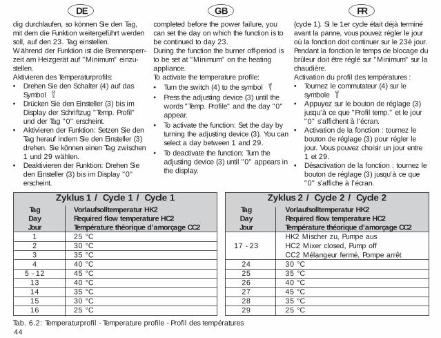
DE GB FR
44
Zyklus 1 / Cycle 1 / Cycle 1Tag Vorlaufsolltemperatur HK2Day Required flow temperature HC2Jour Température théorique d’amorçage CC21 25 °C2 30 °C3 35 °C4 40 °C
5 - 12 45 °C13 40 °C14 35 °C15 30 °C16 25 °C
dig durchlaufen, so können Sie den Tag,mit dem die Funktion weitergeführt werdensoll, auf den 23. Tag einstellen.Während der Funktion ist die Brennersperr-zeit am Heizgerät auf "Minimum" einzu-stellen. Aktivieren des Temperaturprofils:• Drehen Sie den Schalter (4) auf das
Symbol • Drücken Sie den Einsteller (3) bis im
Display der Schriftzug "Temp. Profil"und der Tag "0" erscheint.
• Aktivieren der Funktion: Setzen Sie denTag herauf indem Sie den Einsteller (3)drehen. Sie können einen Tag zwischen1 und 29 wählen.
• Deaktivieren der Funktion: Drehen Sieden Einsteller (3) bis im Display "0"erscheint.
completed before the power failure, youcan set the day on which the function is tobe continued to day 23. During the function the burner off-period isto be set at "Minimum" on the heatingappliance. To activate the temperature profile:• Turn the switch (4) to the symbol • Press the adjusting device (3) until the
words "Temp. Profile" and the day "0"appear.
• To activate the function: Set the day byturning the adjusting device (3). You canselect a day between 1 and 29.
• To deactivate the function: Turn theadjusting device (3) until "0" appears inthe display.
(cycle 1). Si le 1er cycle était déjà terminéavant la panne, vous pouvez régler le jouroù la fonction doit continuer sur le 23è jour.Pendant la fonction le temps de blocage dubrûleur doit être réglé sur "Minimum" sur lachaudière. Activation du profil des températures :• Tournez le commutateur (4) sur le
symbole • Appuyez sur le bouton de réglage (3)
jusqu’à ce que "Profil temp." et le jour"0" s’affichent à l’écran.
• Activation de la fonction : tournez lebouton de réglage (3) pour régler lejour. Vous pouvez choisir un jour entre1 et 29.
• Désactivation de la fonction : tournez lebouton de réglage (3) jusqu’à ce que"0" s’affiche à l’écran.
Tab. 6.2: Temperaturprofil - Temperature profile - Profil des températures
Zyklus 2 / Cycle 2 / Cycle 2Tag Vorlaufsolltemperatur HK2Day Required flow temperature HC2Jour Température théorique d’amorçage CC2
HK2 Mischer zu, Pumpe aus17 - 23 HC2 Mixer closed, Pump off
CC2 Mélangeur fermé, Pompe arrêt24 30 °C25 35 °C26 40 °C27 45 °C28 35 °C29 25 °C
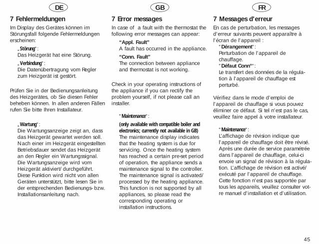
DE GB FR
45
7 FehlermeldungenIm Display des Gerätes können imStörungsfall folgende Fehlermeldungenerscheinen:
„Störung“:Das Heizgerät hat eine Störung.„Verbindung“: Die Datenübertragung vom Reglerzum Heizgerät ist gestört.
Prüfen Sie in der Bedienungsanleitungdes Heizgerätes, ob Sie diesen Fehlerbeheben können. In allen anderen Fällenrufen Sie bitte Ihren Installateur.
„Wartung“: Die Wartungsanzeige zeigt an, dassdas Heizgerät gewartet werden soll. Nach einer im Heizgerät eingestelltenBetriebsdauer sendet das Heizgerätan den Regler ein Wartungssignal. Die Wartungsanzeige wird vomHeizgerät aktiviert/durchgeführt.Diese Funktion wird nicht von allenGeräten unterstützt, bitte lesen Sie inder entsprechenden Bedienungs- bzw.Installationsanleitung nach.
7 Error messagesIn case of a fault with the thermostat thefollowing error messages can appear:
“Appl. Fault”A fault has occurred in the appliance.“Conn. Fault”The connection between applianceand thermostat is not working.
Check in your operating instructions ofthe appliance if you can rectify the problem yourself, if not please call aninstaller.
“Maintenance“: (only available with compatible boiler andelectronics; currently not available in GB)The maintenance display indicatesthat the heating system is due forservicing. Once the heating systemhas reached a certain pre-set periodof operation, the appliance sends amaintenance signal to the controller.The maintenance signal is activated/processed by the heating appliance.This function is not supported by allappliances, so please read thecorresponding operating orinstallation instructions.
7 Messages d'erreur En cas de perturbation, les messagesd'erreur suivants peuvent apparaître àl'écran de l'appareil :
“Dérangement“:Perturbation de l'appareil dechauffage.“Défaut Conn°“:Le transfert des données de la régula-tion à l'appareil de chauffage estperturbé.
Vérifiez dans le mode d’emploi del'appareil de chauffage si vous pouvezéliminer ce défaut. Si tel n'est pas le cas,veuillez faire appel à votre installateur.
“Maintenance“: L'affichage de révision indique quel'appareil de chauffage doit être révisé.Après une durée de service paramétréedans l'appareil de chauffage, celui-cienvoie un signal de révision à la régula-tion. L'affichage de révision est activé/exécuté par l'appareil de chauffage.Cette fonction n'est pas supportée partous les appareils, veuillez consulter vot-re manuel d'installation et d'utilisation.

DE GB FR
46
8 FrostschutzIhr Regelgerät ist mit einer Frostschutz-funktion ausgestattet. Sinkt die Außen-temperatur unter einen Wert von +3 °Cwird automatisch eine Heizungs-Vor-laufsolltemperatur von mindestens 21 °Cvorgegeben.
Nur wirksam, wenn das Heizgerätnicht vom Netz getrennt ist.
9 DatenübertragungJe nach örtlichen Gegebenheiten kann esbis zu 15 Minuten dauern, bis alle Daten(Außentemperatur, DCF, Gerätestatususw.) aktualisiert sind.
8 Frost protectionYour thermostat is equipped with a frostprotection function. If the outside temperature falls below +3 °C the heating automatically turns on and provides heating up to at least 21 °C.
This feature will only operate if theelectrical supply to the appliance isturned on.
9 Data transferDepending on local circumstances, therecan be a delay of up to 15 minutes untilall data (outside temperature, systemstatus, etc.) are updated.
8 Protection contre le gelVotre régulation est équipée d'une fonction de protection contre le gel. Si la température extérieure descend au-dessous de +3 °C, une température deconsigne de chauffage départ d'au moins21 °C est prédéfinie.
Ne fonctionne que si l'appareil dechauffage est connecté au secteur.
9 Transfert de donnéesSelon les conditions locales, cela peutprendre 15 minutes pour que toutes lesdonnées (température extérieure, statut del'appareil etc..) soient actualisées.
DE GB FR
47
10 TelefonfernsteuerungDie Heizungsanlage kann über eine Kom-munikationsschnittstelle (Zubehör) fernge-steuert werden. Gesteuert werden unteranderem die Betriebsart und die Raum-solltemperatur (beachten Sie dieInstallationsanleitung des Zubehörs).Bei Fernsteuerung erscheint im Displaydas Symbol , die eingestellte Raumsoll-temperatur und die ferngesteuerteBetriebsart.Durch Betätigen des Betriebsartenschaltersoder des Tag-Temperaturwählers wird dieFernsteuerung beendet.
11 WerkseinstellungWollen Sie das Regelgerät auf dieWerkeinstellungen zurücksetzen, sodrücken Sie die Partytaste (2) und denEinsteller (3) gleichzeitig (hintereKlappseite, Seite 74) im Display blinktder Schriftzug „Werkseinst.“. Halten Siedie beiden Tasten solange gedrückt, bisder Schriftzug aufhört zu blinken, erstdann werden die Daten zurückgesetzt.
10 Remote control by telephone(Not currently available in GB)The heating system can be controlledremotely by means of a communicationsinterface (accessory). This controls,among other things, the operating modeand the required room temperature(follow the installation instructions for theaccessory).When remote control is being used, thedisplay shows the symbol , therequired roomtemperature that has been set and theremote controlled operating mode.By activating the function switch or theday temperature selector, the remotecontrol function is discontinued.
11 Factory-adjusted elementsIf you wish to return the device to itsfactory-adjusted default settings, press the“party“ button (2) and the adjuster (3) atthe same time (rear-face of panel, page74). The display shows the flashing“default set.“ message. Keep both buttons pressed until messagestops flashing. The data can now bereset.
10 Commande à distance partéléphone La chaudière peut être commandée àdistance par le biais d’une interface decommunication (accessoire). Le mode et latempérature théorique de la pièce peuvententre autres être commandés (respectez lesinstructions d’installation de l’accessoire).En cas de commande à distance, lesymbole , la température théoriqueréglée de la pièce et le mode demandéapparaissent à l’écran.Appuyez sur le commutateur de mode ou lesélecteur de température diurne pour quitterla commande à distance.
11 Réglage usineSi vous voulez revenir au réglage usineinitial, pressez la touche Party (2) et lesélecteur (3) simultanément (rabat arrière,page 74). L'inscription „réglage usine.“clignote. Maintenez les deux touchesenfoncées jusqu'à ce que l'inscription neclignote plus, les données sont alorsréinitialisées.
48
12 WerksgarantieWerksgarantie gewähren wir nur beiInstallation durch einen anerkanntenFachhandwerksbetrieb.Dem Eigentümer des Gerätes räumen wireine Werksgarantie entsprechend denlandesspezifischen Vaillant Geschäftsbe-dingungen ein. Garantiearbeiten werdengrundsätzlich nur von unserem Werks-kundendienst (Deutschland, Österreich)oder durch einen anerkannten Fachhand-werksbetrieb (Schweiz) ausgeführt.Wir können Ihnen daher etwaige Kosten,die Ihnen bei der Durchführung vonArbeiten an dem Gerät während derGarantiezeit entstehen, nur dann er-statten, falls wir Ihnen einen entsprechen-den Auftrag erteilt haben und es sich umeinen Garantiefall handelt.
12 Manufacturer’s WarrantyWe provide a manufacturer’s warrantyonly when a recognised specialist hascarried out the installation.
We grant a manufacturer’s warranty tothe owner of the appliance according tothe specific Vaillant terms of business forthe country. Warranty work must only becarried out by our company’s customerservice department. Because of that, wecan only then refund any expense to you,which you have incurred from workcarried out on your appliance during thewarranty period, if we have placed anappropriate order with you and it is awarranty case.
12 Garantie usinePour la FranceVous venez d’acquérir un appareilVAILLANT. Félicitations !VAILLANT, leader européen pour lafabrication des chaudières gaz, assure lagarantie des appareils VAILLANT dans lecadre de la législation en vigueur (Loi78-12 du 4/10/78).Pour bénéficier de la garantie légale dedeux ans, l’appareil doit impérativementêtre installé par un professionnel qualifié,suivant les règles de l’art et normes envigueur.
D’autre paysNous accordons une garantie usineuniquement pour les installations faitespar des professionnels qualifiés.Nous accordons une garantie aupropriétaire de l’appareil conformémentaux conditions spécifiques du pays. Lestravaux de garantie ne sont exécutés quepar notre SAV usine (Allemagne,Autriche) ou par un SAV professionnel(Suisse).Nous ne pouvons donc vous remboursercertains coûts engendrés par des travauxsur les appareils durant la période degarantie, si nous vous avons fait uncontrat correspondant et s’il s’agit d’uncas de garantie.
DE GB FR
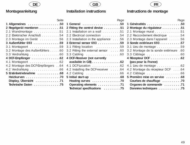
DE GB FR
49
Montageanleitung
Seite1 Allgemeines . . . . . . . . . . . . . . . . .502 Regelgerät montieren . . . . . . . . . . .512.1 Wandmontage . . . . . . . . . . . . .512.2 Elektrischer Anschluß . . . . . . . . .542.3 Montage im Gerät . . . . . . . . . .563 Außenfühler 693 . . . . . . . . . . . . . .593.1 Montageort . . . . . . . . . . . . . . .593.2 Montage des Außenfühlers . . . . .603.3 Verdrahtung . . . . . . . . . . . . . . .604 DCF-Empfänger . . . . . . . . . . . . . . .624.1 Montageort . . . . . . . . . . . . . . .624.2 Montage des DCF-Empfängers . .644.2 Verdrahtung . . . . . . . . . . . . . . .665 Erstinbetriebnahme . . . . . . . . . . . .686 Heizkurven . . . . . . . . . . . . . . . . . .706 Display, Übersicht . . . . . . . . . . . . .716 Technische Daten . . . . . . . . . . . . . .75
Installation instructions
Page1 General . . . . . . . . . . . . . . . . . . . .502 Fitting the control device . . . . . . . . .512.1 Installation on a wall . . . . . . . . .512.2 Electrical connection . . . . . . . . .542.3 Installation in the appliance . . . .563 External sensor 693 . . . . . . . . . . . .593.1 Fitting location . . . . . . . . . . . .593.2 Fitting the external sensor . . . . .603.3 Cabling . . . . . . . . . . . . . . . . .604 DCF-Receiver (not currently 4 available in GB) . . . . . . . . . . . . . . .624.1 DCF-Location . . . . . . . . . . . . . .624.2 Installing the DCF-receiver . . . . .644.2 Cabling . . . . . . . . . . . . . . . . .665 Initial start-up . . . . . . . . . . . . . . . .686 Heating curves . . . . . . . . . . . . . . .706 Operating elements . . . . . . . . . . . .716 Technical specifications . . . . . . . . .75
Instructions de montage
Page1 Génératités . . . . . . . . . . . . . . . . . .502 Montage du régulateur . . . . . . . . . .512.1 Montage mural . . . . . . . . . . . . .512.2 Raccordement électrique . . . . . .542.3 Montage dans l’appareil . . . . . .563 Sonde extérieure 693 . . . . . . . . . . .573.1 Lieu de montage . . . . . . . . . . . .593.2 Montage de la sonde extérieure .603.3 Câblage . . . . . . . . . . . . . . . . .604 Récepteur DCF . . . . . . . . . . . . . . . .624 (pas pour la France)4.1 Lieu de montage . . . . . . . . . . . .624.2 Montage du récepteur DCF . . . .644.2 Câblage . . . . . . . . . . . . . . . . .665 Première mise en service . . . . . . . .686 Courbes de chauffage . . . . . . . . . .706 Organes de commande . . . . . . . . .716 Données techniques . . . . . . . . . . . .75
DE GB FR
50
1 Allgemeines
Die Montage, der elektrischeAnschluß, die Einstellungen imGerät sowie die Erstinbetrieb-nahme dürfen nur durch einenanerkannten Fachhandwerks-betrieb vorgenommen werden!
CE-KennzeichnungMit der CE-Kennzeichnung wirddokumentiert, dass die Regelgeräte VRC410 in Verbindung mit VaillantHeizgeräten die grundlegendenAnforderungen der Richtlinie über dieelektromagnetische Verträglichkeit(Richtlinie 89/336/EWG des Rates)erfüllen.
1 General
The installation, the electricalconnections, the settings withinthe appliance and the commissioning of the applianceshould only be performed by aprofessional installer.
CE-CodingThe CE-coding demonstrates, that thethermostats VRC 410 - in conjunctionwith the Vaillant appliances - comply withthe basic requirements of the guidelinesfor electromagnetic compliance.
1 Généralités
Le montage, le raccordementélectrique, les réglages de l'appareil et la première mise enservice ne doivent être effectuésque par un professionnelqualifié!
Sigle CELe sigle CE prouve que les régulationsVRC 410, connectées aux chaudièresVaillant chauflage, répondent aux exigences fondamentales de la directivesur la compatibilité électromagnétique(directive 89/336/CEE du Conseil).
DE GB FR
51
2 Regelgerät montieren
Das Regelgerät kann direkt im Schalt-kasten des Heizgerätes oder als Fern-bedienungsgerät an einer Wandangebracht werden.
2.1 WandmontageBei Einsatz des Reglers mit Raumtempe-raturaufschaltung ist zur Wandmontagefolgendes zu beachten:Der günstigste Montageort ist meistens imHauptwohnraum an einer Innenwand inca. 1,5 m Höhe.Dort soll das Regelgerät die zirkulierendeRaumluft – ungehindert von Möbeln,Vorhängen oder sonstigen Gegenständen– erfassen können. Der Anbringungsortsoll so gewählt werden, dass weder dieZugluft von Tür oder Fenster nochWärmequellen wie Heizkörper, Kamin-wand, Fernsehgerät oder Sonnenstrahlendas Regelgerät direkt beeinflussenkönnen. Im Zimmer, in dem dasRegelgerät angebracht ist, müssen alleHeizkörper-ventile voll geöffnet sein,wenn die Raumtemperaturaufschaltungaktiviert ist.
2 Installing the thermostat
The thermostat can be installed directlyinto the heating appliance or as a remote thermostat version onto a wall,remote from the appliance.
2.1 Installation on a wall When installing the thermostat on a wall,remote from the appliance, please notethe following:The best place to fix the thermostat isusually in a main living area, on an inside wall at a height of approx. 1.5 m.The thermostat should be freely exposedto the circulating air in the room, andshould not be covered by furniture, curtains or other objects. The exact fixingplace should be chosen in such a way,that the thermostat is not directly exposedto draughts from doors or windows, ordirect heating sources such as radiators,chimney walls, TV’s or sun light. In theroom where the thermostat is installed,radiator valves have to be kept fullyopen at all times.
2 Montage du régulateur
La régulation peut être montéedirectement dans le tableau decommande de l'appareil ou commeappareil à télécommande surun mur.
2.1 Montage muralPour l'emploi de la régulation àcommande de température ambiante, ilfaut tenir compte de ce qui suit pour lemontage mural:Le lieu de montage le plus favorable estgénéralement situé sur un mur intérieurde la pièce d’habitation principale, àune hauteur de 1,5 m.C'est là que la régulation doit capter l'airqui circule dans la pièce, sans que desmeubles, des rideaux ou d'autres objetsne constituent une entrave quelconque.Le lieu de montage doit être choisi detelle sorte que ni les courants d'airprovenant des portes ou des fenêtres, niles sources de chaleur tels que lesradiateurs, les parois des cheminées, lestéléviseurs ou le rayonnement solaire nepuissent influer directement sur larégulation. Dans la pièce où larégulation est installée, tous les robinetsdes radiateurs doivent être complètementouverts en permanence quand la fonctiontempérature ambiante est activée.
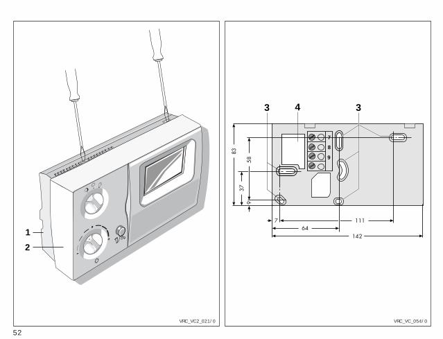
52
1
2+
-
3 3
7
8
9
4
VRC_VC_054/0VRC_VC2_021/0
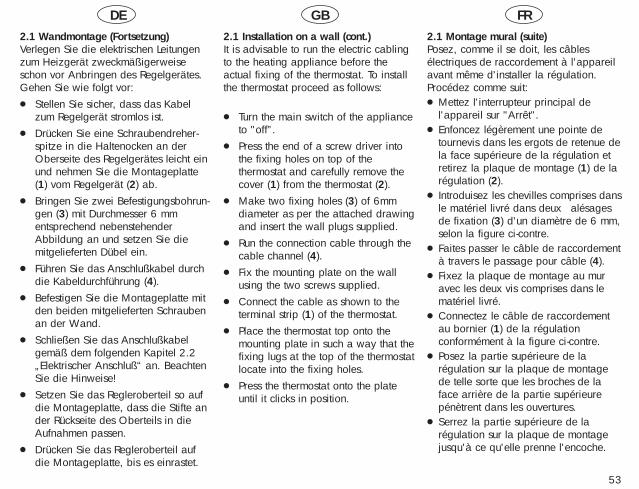
DE GB FR
53
2.1 Wandmontage (Fortsetzung)Verlegen Sie die elektrischen Leitungenzum Heizgerät zweckmäßigerweiseschon vor Anbringen des Regelgerätes.Gehen Sie wie folgt vor:● Stellen Sie sicher, dass das Kabel
zum Regelgerät stromlos ist.● Drücken Sie eine Schraubendreher-
spitze in die Haltenocken an derOberseite des Regelgerätes leicht einund nehmen Sie die Montageplatte(1) vom Regelgerät (2) ab.
● Bringen Sie zwei Befestigungsbohrun-gen (3) mit Durchmesser 6 mmentsprechend nebenstehenderAbbildung an und setzen Sie diemitgelieferten Dübel ein.
● Führen Sie das Anschlußkabel durchdie Kabeldurchführung (4).
● Befestigen Sie die Montageplatte mitden beiden mitgelieferten Schraubenan der Wand.
● Schließen Sie das Anschlußkabelgemäß dem folgenden Kapitel 2.2„Elektrischer Anschluß“ an. BeachtenSie die Hinweise!
● Setzen Sie das Regleroberteil so aufdie Montageplatte, dass die Stifte ander Rückseite des Oberteils in dieAufnahmen passen.
● Drücken Sie das Regleroberteil aufdie Montageplatte, bis es einrastet.
2.1 Installation on a wall (cont.)It is advisable to run the electric cablingto the heating appliance before theactual fixing of the thermostat. To installthe thermostat proceed as follows:
● Turn the main switch of the applianceto "off”.
● Press the end of a screw driver intothe fixing holes on top of the thermostat and carefully remove thecover (1) from the thermostat (2).
● Make two fixing holes (3) of 6mmdiameter as per the attached drawingand insert the wall plugs supplied.
● Run the connection cable through thecable channel (4).
● Fix the mounting plate on the wallusing the two screws supplied.
● Connect the cable as shown to the terminal strip (1) of the thermostat.
● Place the thermostat top onto themounting plate in such a way that thefixing lugs at the top of the thermostatlocate into the fixing holes.
● Press the thermostat onto the plateuntil it clicks in position.
2.1 Montage mural (suite)Posez, comme il se doit, les câblesélectriques de raccordement à l'appareilavant même d'installer la régulation.Procédez comme suit:● Mettez l'interrupteur principal de
l'appareil sur "Arrêt".● Enfoncez légèrement une pointe de
tournevis dans les ergots de retenue dela face supérieure de la régulation etretirez la plaque de montage (1) de larégulation (2).
● Introduisez les chevilles comprises dansle matériel livré dans deux alésagesde fixation (3) d'un diamètre de 6 mm,selon la figure ci-contre.
● Faites passer le câble de raccordementà travers le passage pour câble (4).
● Fixez la plaque de montage au muravec les deux vis comprises dans lematériel livré.
● Connectez le câble de raccordementau bornier (1) de la régulationconformément à la figure ci-contre.
● Posez la partie supérieure de larégulation sur la plaque de montagede telle sorte que les broches de laface arrière de la partie supérieurepénètrent dans les ouvertures.
● Serrez la partie supérieure de larégulation sur la plaque de montagejusqu'à ce qu'elle prenne l'encoche.
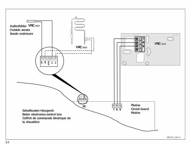
54
789
DC
F
RF
AF 0 0
7 8 9X8
ϑ
VRC 692
VRC 693
VRC 410
VRC-VC_156/2
Schaltkasten HeizgerätBoiler electronics control boxCoffret de commande électrique dela chaudière
PlatineCircuit boardPlatine
AußenfühlerOutside sensorSonde extérieure
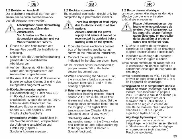
DE GB FR
55
2.2 Elektrischer AnschlußDer elektrische Anschluß darf nur voneinem anerkannten Fachhandwerks-betrieb vorgenommen werden.
Lebensgefahr durch Stromschlagan spannungsführendenAnschlüssen.Vor Arbeiten am Gerät dieStromzufuhr abschalten und vorWiedereinschalten sichern.
● Öffnen Sie den Schaltkasten desHeizgerätes gemäß der Installations-anleitung.
● Nehmen Sie die Anschlußverdrahtunggemäß der nebenstehendenAbbildung vor.
☞ Auf dem Steckplatz X8 im Schalt-kasten des Heizgerätes wird derAußenfühler angeschlossen.
☞ Bei Anschluß des VRC 410 muss eineBrücke zwischen Klemme 3 und 4 desHeizgerätes eingesetzt werden.
☞ Rücklauftemperaturregelung(Fußbodenheizung): Fühler VRC 692im Rücklauf montieren undanschließen. Wegen der um ca. 20°Chöheren Vorlauftemperatur, dieHeizkurve flacher einstellen (sieheKapitel 4.5 und Kapitel 6 unter"Hydraulische Weiche").Hydraulische Weiche: Tauchfühler inder Weiche montieren, entsprechendder Abbildung anschließen undEinstellung (Kapitel 6Sonderfunktionen) anpassen.
2.2 Electrical connectionThe electrical connection should only becompleted by a professional installer.
There is a danger of fatal injurydue to electric shock in all live sections. ALWAYS shut off the powersupply and ensure it cannot bereconnected by accident beforestarting work on the system.
● Open the boiler electronics controlbox of the heating appliance asshown in the installation instructions.
● Connect the wiring system asindicated in the diagram shown here.
☞ The external sensor is connected toplug-in terminal X8 in the boilerelectronics control box.
☞ When connecting the VRC 410 unit,there must be a bridge connectionbetween terminals 3 and 4 of theheating appliance.
☞ Return temperature regulation(underfloor heating system): MountSensor VRC 692 in the return flowstream and attach it in place. Set theheating curve somewhat flatter due tothe roughly 20°C higher flowtemperature (see Chapter 4.5 andChapter 6 under "3-way valve").The 3-way valve: Mount thesubmerging sensor in the 3-way valveand connect up and adjust accordingto the figure shown (Chapter 6Special functions).
2.2 Raccordement électriqueLe raccordement électrique ne doit êtreeffectué que par une entreprisespécialisée et reconnue.
Risque d’électrocution sur desbranchements conducteurs detension. Avant les travaux surles appareils, couper l'alimen-tation électrique, en particulierde la chaudiére et protégercontre une remise en route.
● Ouvrez le coffret de commandeélectrique de l'appareil de chauffaged'après les instructions d'installation.
● Procédez au câblage de raccorde-ment d'après la figure ci-contre.
☞ La sonde extérieure est raccordée surle connecteur X8 dans le coffret decommande électrique de l'appareil dechauffage.
☞ Au raccordement du VRC 410 il fautprévoir un pont entre la borne 3 et 4de l'appareil de chauffage.
☞ Régulation de la température dans lecircuit de retour (chauffage par le sol):monter, puis raccorder le palpeurVRC 692 dans le circuit de retour. Enraison de la température allerd'environ 20 °C plus élevée, ilconvient de régler la courbe dechauffe de manière plus plane (voirchapitres 4.5 et 6 au point «aiguillage hydraulique »).Aiguillage hydraulique : monter lepalpeur par immersion dansl'aiguillage, le brancher en se référantà l'illustration et adapter le réglageen conséquence (voir chapitre 6Fonctions spéciales).
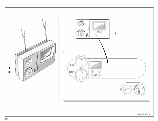
56
bar
21 3
0
Party
Sa - 15°C
°C
VRC-VCC
+10
+2
+3
-1
-2
-3+-
+
-3
4
3
VRC-VC2_022/0
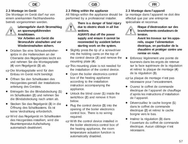
DE GB FR
57
2.3 Montage im GerätDie Montage im Gerät darf nur voneinem anerkannten Fachhandwerks-betrieb vorgenommen werden.
Lebensgefahr durch Stromschlagan spannungsführendenAnschlüssen.Vor Arbeiten am Gerät dieStromzufuhr abschalten und vorWiedereinschalten sichern.
● Drücken Sie eine Schraubendreher-spitze in die Haltenocken an derOberseite des Regelgerätes leicht einund nehmen Sie die Montageplatte(4) vom Regelgerät (3) ab.
☞ Die Montageplatte wird für denEinbau im Gerät nicht benötigt.
● Öffnen Sie den Schaltkasten desHeizgerätes gemäß der Installations-anleitung des Gerätes.
● Entriegeln Sie die Blindabdeckung (1)im Schaltkasten (2) und nehmen Siedie Blindabdeckung nach unten ab.
● Stecken Sie das Regelgerät (3) in dieÖffnung des Schaltkastens. Es istkeine Verdrahtung erforderlich.
☞ Wird das Regelgerät im Schaltkastendes Heizgerätes installiert, wird dieRaumtemperatur-Aufschaltungautomatisch deaktiviert.
2.3 Fitting within the appliance All fittings within the appliance should beperformed by a professional installer.
There is a danger of fatal injurydue to electric shock in all live sections. ALWAYS shut off the powersupply and ensure it cannot bereconnected by accident beforestarting work on the system.
● Slightly press the tip of a screwdriverinto the holding cams on the top ofthe control device (3) and remove themounting plate (4).
☞ This mounting plate is not needed forthe installation of the control device.
● Open the boiler electronics controlbox of the heating applianceaccording to the installationinstruction accompanying theappliance.
● Unlock the blind cover (1) inside theswitchbox (2) and remove it frombelow.
● Plug the control device (3) into theopening of the boiler electronicscontrol box. There is no wiringrequired.
☞ With the control device installed inthe boiler electronics control box ofthe heating appliance, the roomtemperature actuation function isautomatically disabled.
2.3 Montage dans l'appareilLe montage dans l'appareil ne doit êtreeffectué que par une entreprisespécialisée et reconnue.
Risque d’électrocution sur desbranchements conducteurs detension.Avant les travaux sur les appa-reils, couper l'alimentationélectrique, en particulier de lachaudiére et protéger contre uneremise en route.
● Enfoncez légèrement une pointe detournevis dans les ergots de retenuesur la face supérieure de la régulationet retirez la plaque de montage (4)de la régulation (3).
☞ La plaque de montage n'est pasnécessaire pour l'encastrement.
● Ouvrez le coffret de commandeélectrique de l'appareil de chauffaged'après les instructions d'installationde l'appareil.
● Déverrouillez le cache borgne (1)dans le coffret de commandeélectrique (2) et retirez le cacheborgne vers le bas.
● Insérez la régulation (3) dansl'ouverture du coffret de commandeélectrique. Aucun câblage n'estnécessaire.
DE GB FR
58
2.3 Montage im Gerät (Fortsetzung)● Schließen Sie den Schaltkasten des
Heizgerätes gemäß derInstallationsanleitung.
● Schalten Sie die Stromzufuhr wiederein und stellen Sie den Hauptschalterdes Heizgerätes auf „I“.
2.3 Montage dans l'appareil (suite)
☞ Si la régulation est installée dans lecoffret de commande électrique, lacommande de température ambianteest désactivée automatiquement.
● Fermez le coffret de commandeélectrique de l'appareil de chauffaged'après les instructions d'installation.
● Rebranchez l'alimentation électriqueet mettez l'interrupteur principal del'appareil de chauffage sur „I“.
2.3 Fitting within the appliance (continued)
● Close the boiler electronics controlbox of the heating appliance asshown in the installation instructions.
● Reconnect the power supply andmove the heating appliance masterswitch back to position “I“.

DE GB FR
59
3 External sensor VRC 693
3.1 Fitting locationThe external sensor should be attached tothe side of the building that correspondsto the rooms that are used most often. Ifthis location cannot be clearly-defined,the sensor should be fitted to the north ornorth-west facing wall.
For optimum outside temperaturedetection, the appliance should (inbuildings of up to three stories) be fittedabout two-thirds up the frontage.On higher buildings, the sensor shouldbe fitted between the second and thirdfloors.Ensure that the attachment point isneither protected from wind norexcessively exposed to the weather or todirect sunlight. The appliance should beat least three feet from any opening inthe outside wall from which hot air flows(either permanently or intermittently).
Depending on the accessibility of thelocation the appliance can be surface-mounted or embedded in the wall.
3 Sonde extérieure VRC 693
3.1 Lieu de montageLa mise en place de la sonde extérieuredoit se faire sur un côté de la maison oùse trouvent les pièces les plus utilisées. Sice côté n'est pas clairement défini, lamise en place doit s'effectuer sur le côtéNord-Nord Ouest de la maison.
Pour la saisie optimale de la températureextérieure, l'appareil doit être placé àenviron au 2/3 de la hauteur de façadepour des bâtiments de 3 étagesmaximum. Pour des bâtiments plus élevés,l'emplacement est recommandé entre le2 ième et le 3ième étage.Le lieu de mise en place ne doit être àl'abri ni du vent ni des courants d'air, niêtre exposé à l'ensoleillement direct.L'appareil doit être placé à au moins 1 mètre de distance d'ouvertures dansles murs extérieurs d'où peut sortir del'air chaud en permanence ou de tempsen temps.
Selon l'accessibilité du lieu de montage,on peut choisir entre la version montagemural ou encastrement.
3 Außenfühler VRC 693
3.1 MontageortDie Anbringung des Außenfühlers solltean der Seite des Hauses erfolgen, aufder die meistbenutzten Räume liegen.Falls diese Seite nicht eindeutig festgelegtwerden kann, ist die Anbringung an derNord- oder Nord-West-Seite des Hausesvorzunehmen.
Für die optimale Erfassung der Außen-temperatur sollte das Gerät bei Gebäu-den bis zu 3 Geschossen in ungefähr2/3 Fassadenhöhe angebracht werden.Bei höheren Gebäuden ist die Anbrin-gung zwischen dem 2. und 3. Geschoßzu empfehlen.Der Anbringungsort sollte wederwindgeschützt, noch besonders zugiggelegen und nicht der direktenSonnenbestrahlung ausgesetzt sein. VonÖffnungen in der Außenwand, ausdenen ständig oder zeitweise Warmluftströmen kann, muß das Gerät mindestens1 m Abstand haben.
Je nach Zugänglichkeit des Montageorteskann die Wandaufbau- oder Wandein-bau-Ausführung gewählt werden.
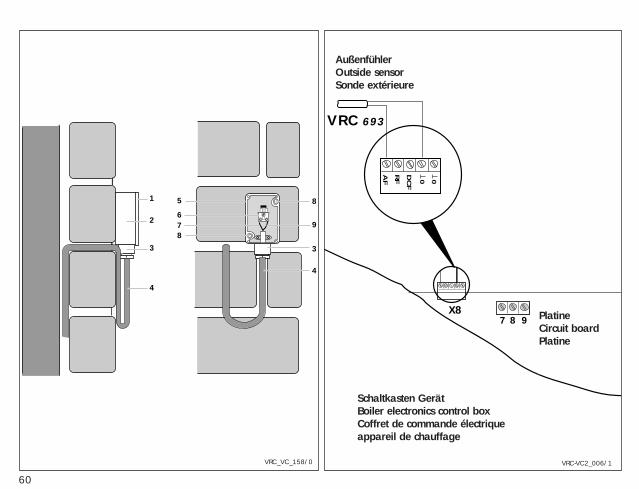
60
1
2
3
4
8
9
3
4
5
678
VRC_VC_158/0
DC
F
RF
AF 0 0
7 8 9X8
VRC 693
VRC-VC2_006/1
Schaltkasten GerätBoiler electronics control boxCoffret de commande électriqueappareil de chauffage
PlatineCircuit boardPlatine
AußenfühlerOutside sensorSonde extérieure
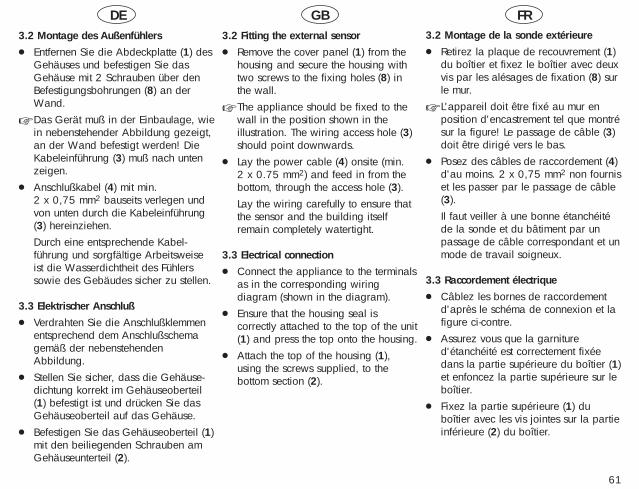
DE GB FR
61
3.2 Montage des Außenfühlers● Entfernen Sie die Abdeckplatte (1) des
Gehäuses und befestigen Sie dasGehäuse mit 2 Schrauben über denBefestigungsbohrungen (8) an derWand.
☞ Das Gerät muß in der Einbaulage, wiein nebenstehender Abbildung gezeigt,an der Wand befestigt werden! DieKabeleinführung (3) muß nach untenzeigen.
● Anschlußkabel (4) mit min.2 x 0,75 mm2 bauseits verlegen undvon unten durch die Kabeleinführung(3) hereinziehen. Durch eine entsprechende Kabel-führung und sorgfältige Arbeitsweiseist die Wasserdichtheit des Fühlerssowie des Gebäudes sicher zu stellen.
3.3 Elektrischer Anschluß● Verdrahten Sie die Anschlußklemmen
entsprechend dem Anschlußschemagemäß der nebenstehendenAbbildung.
● Stellen Sie sicher, dass die Gehäuse-dichtung korrekt im Gehäuseoberteil(1) befestigt ist und drücken Sie dasGehäuseoberteil auf das Gehäuse.
● Befestigen Sie das Gehäuseoberteil (1)mit den beiliegenden Schrauben amGehäuseunterteil (2).
3.2 Fitting the external sensor● Remove the cover panel (1) from the
housing and secure the housing withtwo screws to the fixing holes (8) inthe wall.
☞ The appliance should be fixed to thewall in the position shown in theillustration. The wiring access hole (3)should point downwards.
● Lay the power cable (4) onsite (min. 2 x 0.75 mm2) and feed in from thebottom, through the access hole (3).Lay the wiring carefully to ensure thatthe sensor and the building itselfremain completely watertight.
3.3 Electrical connection● Connect the appliance to the terminals
as in the corresponding wiringdiagram (shown in the diagram).
● Ensure that the housing seal iscorrectly attached to the top of the unit(1) and press the top onto the housing.
● Attach the top of the housing (1),using the screws supplied, to thebottom section (2).
3.2 Montage de la sonde extérieure● Retirez la plaque de recouvrement (1)
du boîtier et fixez le boîtier avec deuxvis par les alésages de fixation (8) surle mur.
☞ L'appareil doit être fixé au mur enposition d'encastrement tel que montrésur la figure! Le passage de câble (3)doit être dirigé vers le bas.
● Posez des câbles de raccordement (4)d'au moins. 2 x 0,75 mm2 non fourniset les passer par le passage de câble(3). Il faut veiller à une bonne étanchéitéde la sonde et du bâtiment par unpassage de câble correspondant et unmode de travail soigneux.
3.3 Raccordement électrique● Câblez les bornes de raccordement
d'après le schéma de connexion et lafigure ci-contre.
● Assurez vous que la garnitured'étanchéité est correctement fixéedans la partie supérieure du boîtier (1)et enfoncez la partie supérieure sur leboîtier.
● Fixez la partie supérieure (1) duboîtier avec les vis jointes sur la partieinférieure (2) du boîtier.
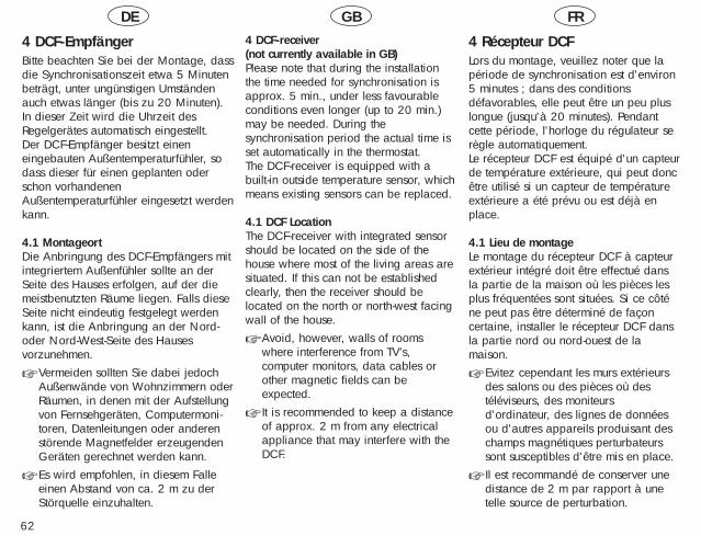
62
4 DCF-EmpfängerBitte beachten Sie bei der Montage, dassdie Synchronisationszeit etwa 5 Minutenbeträgt, unter ungünstigen Umständenauch etwas länger (bis zu 20 Minuten).In dieser Zeit wird die Uhrzeit desRegelgerätes automatisch eingestellt.Der DCF-Empfänger besitzt eineneingebauten Außentemperaturfühler, sodass dieser für einen geplanten oderschon vorhandenenAußentemperaturfühler eingesetzt werdenkann.
4.1 MontageortDie Anbringung des DCF-Empfängers mitintegriertem Außenfühler sollte an derSeite des Hauses erfolgen, auf der diemeistbenutzten Räume liegen. Falls dieseSeite nicht eindeutig festgelegt werdenkann, ist die Anbringung an der Nord-oder Nord-West-Seite des Hausesvorzunehmen.
☞ Vermeiden sollten Sie dabei jedochAußenwände von Wohnzimmern oderRäumen, in denen mit der Aufstellungvon Fernsehgeräten, Computermoni-toren, Datenleitungen oder anderenstörende Magnetfelder erzeugendenGeräten gerechnet werden kann.
☞ Es wird empfohlen, in diesem Falleeinen Abstand von ca. 2 m zu derStörquelle einzuhalten.
4 DCF-receiver (not currently available in GB)Please note that during the installationthe time needed for synchronisation isapprox. 5 min., under less favourableconditions even longer (up to 20 min.)may be needed. During the synchronisation period the actual time isset automatically in the thermostat.The DCF-receiver is equipped with abuilt-in outside temperature sensor, whichmeans existing sensors can be replaced.
4.1 DCF LocationThe DCF-receiver with integrated sensorshould be located on the side of thehouse where most of the living areas aresituated. If this can not be establishedclearly, then the receiver should be located on the north or north-west facingwall of the house.
☞ Avoid, however, walls of roomswhere interference from TV’s, computer monitors, data cables orother magnetic fields can be expected.
☞ It is recommended to keep a distanceof approx. 2 m from any electricalappliance that may interfere with theDCF.
4 Récepteur DCFLors du montage, veuillez noter que lapériode de synchronisation est d'environ5 minutes ; dans des conditionsdéfavorables, elle peut être un peu pluslongue (jusqu'à 20 minutes). Pendantcette période, l'horloge du régulateur serègle automatiquement.Le récepteur DCF est équipé d'un capteurde température extérieure, qui peut doncêtre utilisé si un capteur de températureextérieure a été prévu ou est déjà enplace.
4.1 Lieu de montageLe montage du récepteur DCF à capteurextérieur intégré doit être effectué dansla partie de la maison où les pièces lesplus fréquentées sont situées. Si ce côténe peut pas être déterminé de façoncertaine, installer le récepteur DCF dansla partie nord ou nord-ouest de lamaison.
☞ Evitez cependant les murs extérieursdes salons ou des pièces où destéléviseurs, des moniteursd'ordinateur, des lignes de donnéesou d'autres appareils produisant deschamps magnétiques perturbateurssont susceptibles d'être mis en place.
☞ Il est recommandé de conserver unedistance de 2 m par rapport à unetelle source de perturbation.
DE GB FR
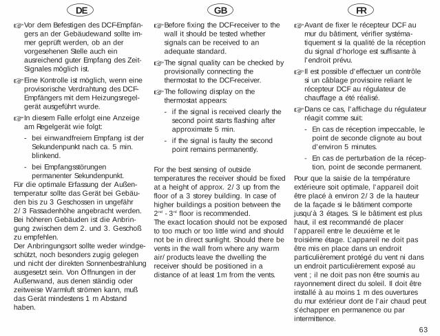
DE GB FR
63
☞ Vor dem Befestigen des DCF-Empfän-gers an der Gebäudewand sollte im-mer geprüft werden, ob an dervorgesehenen Stelle auch einausreichend guter Empfang des Zeit-Signales möglich ist.
☞ Eine Kontrolle ist möglich, wenn eineprovisorische Verdrahtung des DCF-Empfängers mit dem Heizungsregel-gerät ausgeführt wurde.
☞ In diesem Falle erfolgt eine Anzeigeam Regelgerät wie folgt:- bei einwandfreiem Empfang ist der
Sekundenpunkt nach ca. 5 min.blinkend.
- bei Empfangsstörungenpermanenter Sekundenpunkt.
Für die optimale Erfassung der Außen-temperatur sollte das Gerät bei Gebäu-den bis zu 3 Geschossen in ungefähr2/3 Fassadenhöhe angebracht werden.Bei höheren Gebäuden ist die Anbrin-gung zwischen dem 2. und 3. Geschoßzu empfehlen.Der Anbringungsort sollte weder windge-schützt, noch besonders zugig gelegenund nicht der direkten Sonnenbestrahlungausgesetzt sein. Von Öffnungen in derAußenwand, aus denen ständig oderzeitweise Warmluft strömen kann, mußdas Gerät mindestens 1 m Abstandhaben.
☞ Before fixing the DCF-receiver to thewall it should be tested whether signals can be received to an adequate standard.
☞ The signal quality can be checked byprovisionally connecting the thermostat to the DCF-receiver.
☞ The following display on the thermostat appears:- if the signal is received clearly the
second point starts flashing afterapproximate 5 min.
- if the signal is faulty the secondpoint remains permanently.
For the best sensing of outside temperatures the receiver should be fixedat a height of approx. 2/3 up from thefloor of a 3 storey building. In case ofhigher buildings a position between the2nd - 3rd floor is recommended.The exact location should not be exposedto too much or too little wind and shouldnot be in direct sunlight. Should there bevents in the wall from where any warmair/products leave the dwelling thereceiver should be positioned in adistance of at least 1m from the vents.
☞ Avant de fixer le récepteur DCF aumur du bâtiment, vérifier systéma-tiquement si la qualité de la réceptiondu signal d'horloge est suffisante àl'endroit prévu.
☞ Il est possible d'effectuer un contrôlesi un câblage provisoire reliant lerécepteur DCF au régulateur dechauffage a été réalisé.
☞ Dans ce cas, l'affichage du régulateurréagit comme suit:- En cas de réception impeccable, le
point de seconde clignote au boutd'environ 5 minutes.
- En cas de perturbation de la récep-tion, point de seconde permanent.
Pour que la saisie de la températureextérieure soit optimale, l'appareil doitêtre placé à environ 2/3 de la hauteurde la façade si le bâtiment comportejusqu'à 3 étages. Si le bâtiment est plushaut, il est recommandé de placerl'appareil entre le deuxième et letroisième étage. L'appareil ne doit pasêtre mis en place dans un endroitparticulièrement protégé du vent ni dansun endroit particulièrement exposé auvent ; il ne doit pas non être soumis aurayonnement direct du soleil. Il doit êtreinstallé à au moins 1 m des ouverturesdu mur extérieur dont de l'air chaud peuts’échapper en permanence ou parintermittence.
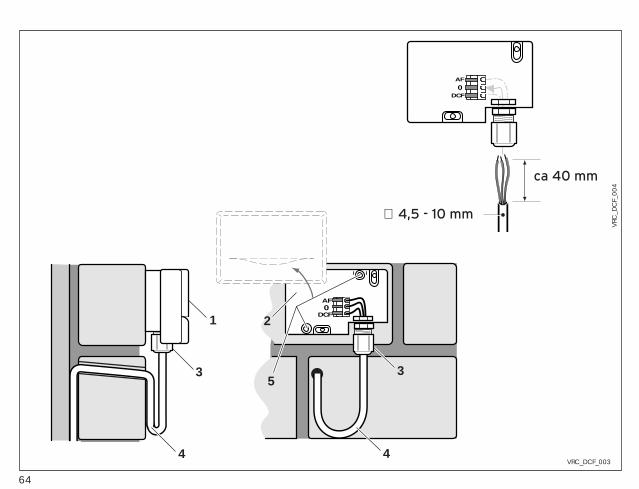
64
44
3 3
1 2
5
DCF0AF
VRC_DCF_003
ca 40 mm
∅ 4,5 - 10 mm
DCF0
AF
VRC
_DC
F_00
4
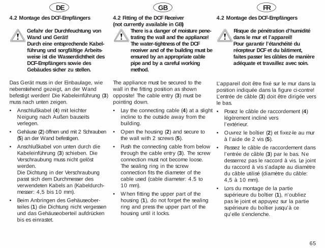
DE GB FR
65
4.2 Montage des DCF-Empfängers
Gefahr der Durchfeuchtung vonWand und Gerät!Durch eine entsprechende Kabel-führung und sorgfältige Arbeits-weise ist die Wasserdichtheit desDCF-Empfängers sowie desGebäudes sicher zu stellen.
Das Gerät muss in der Einbaulage, wienebenstehend gezeigt, an der Wandbefestigt werden! Die Kabeleinführung (3)muss nach unten zeigen.• Anschlußkabel (4) mit leichter
Neigung nach Außen bauseitsverlegen.
• Gehäuse (2) öffnen und mit 2 Schrauben(5) an der Wand befestigen.
• Anschlußkabel von unten durch dieKabeleinführung (3) schieben. DieVerschraubung muss nicht gelöstwerden. Die Dichtung in der Verschraubungpasst sich dem Durchmesser desverwendeten Kabels an (Kabeldurch-messer: 4,5 bis 10 mm).
• Beim Anbringen des Gehäuseober-teiles (1) die Dichtung nicht vergessenund das Gehäuseoberteil aufdrückenbis es einrastet.
4.2 Fitting of the DCF Receiver(not currently available in GB)
There is a danger of moisture pene-trating the wall and the appliance!The water-tightness of the DCFreceiver and of the building must beensured by an appropriate cablepipe and by a careful workingmethod.
The appliance must be secured to thewall in the fitting position as shownopposite! The cable entry (3) must bepointing down.• Lay the connecting cable (4) at a slight
incline to the outside away from thebuilding.
• Open the housing (2) and secure tothe wall with 2 screws (5).
• Push the connecting cable from belowthrough the cable entry (3). The screwconnection must not become loose. The sealing ring in the screwconnection fits the diameter of thecable used (cable diameter: 4.5 to10 mm).
• When fitting the upper part of thehousing (1), do not forget the sealingring and press the upper part of thehousing until it locks.
4.2 Montage des DCF-Empfängers
Risque de pénétration d’humiditédans le mur et l’appareil!Pour garantir l’étanchéité durécepteur DCF et du bâtiment,faites passer les câbles de manièreadéquate et travaillez avec soin.
L'appareil doit être fixé sur le mur dans laposition indiquée dans la figure ci-contre!L'entrée de câble (3) doit être dirigée versle bas.• Posez le câble de raccordement (4)
légèrement incliné vers l’extérieur.
• Ouvrez le boîtier (2) et fixez-le au murà l’aide de 2 vis (5).
• Passez le câble de raccordement dansl’entrée de câble (3) par le bas. Nedesserrez pas le raccord à vis. Le jointdu raccord à vis s’adapte au diamètredu câble utilisé (diamètre du câble:4,5 à 10 mm).
• Lors du montage de la partiesupérieure du boîtier (1), n’oubliezpas le joint et appuyez sur la partiesupérieure du boîtier jusqu’à cequ’elle s’enclenche.
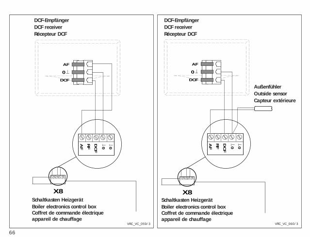
66
DCF
0
AF
DC
F
RF
AF 0 0
X8
DCF
0
AF
DC
F
RF
AF 0 0
X8
VRC_VC_060/3VRC_VC_059/3
Schaltkasten HeizgerätBoiler electronics control boxCoffret de commande électriqueappareil de chauffage
DCF-EmpfängerDCF receiverRécepteur DCF
Schaltkasten HeizgerätBoiler electronics control boxCoffret de commande électriqueappareil de chauffage
DCF-EmpfängerDCF receiverRécepteur DCF
AußenfühlerOutside sensorCapteur extérieure
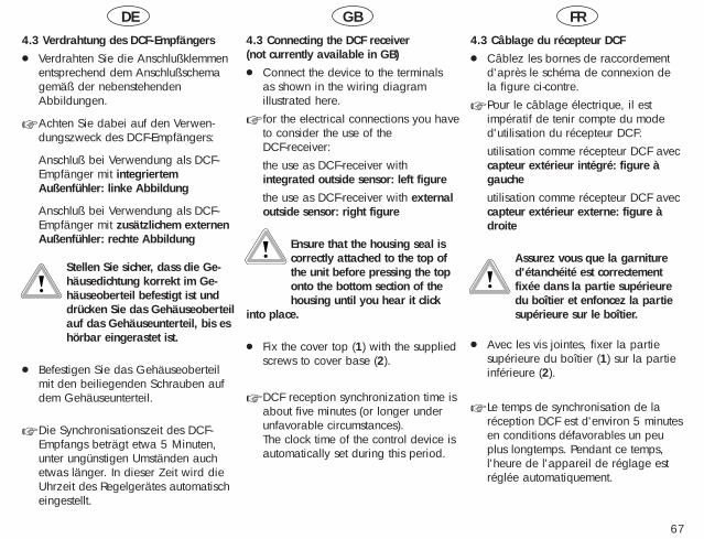
DE GB FR
67
4.3 Verdrahtung des DCF-Empfängers● Verdrahten Sie die Anschlußklemmen
entsprechend dem Anschlußschemagemäß der nebenstehendenAbbildungen.
☞ Achten Sie dabei auf den Verwen-dungszweck des DCF-Empfängers:
Anschluß bei Verwendung als DCF-Empfänger mit integriertemAußenfühler: linke Abbildung
Anschluß bei Verwendung als DCF-Empfänger mit zusätzlichem externenAußenfühler: rechte Abbildung
Stellen Sie sicher, dass die Ge-häusedichtung korrekt im Ge-häuseoberteil befestigt ist unddrücken Sie das Gehäuseoberteilauf das Gehäuseunterteil, bis eshörbar eingerastet ist.
● Befestigen Sie das Gehäuseoberteilmit den beiliegenden Schrauben aufdem Gehäuseunterteil.
☞ Die Synchronisationszeit des DCF-Empfangs beträgt etwa 5 Minuten,unter ungünstigen Umständen auchetwas länger. In dieser Zeit wird dieUhrzeit des Regelgerätes automatischeingestellt.
4.3 Connecting the DCF receiver(not currently available in GB)● Connect the device to the terminals
as shown in the wiring diagram illustrated here.
☞ for the electrical connections you haveto consider the use of the DCF-receiver:the use as DCF-receiver withintegrated outside sensor: left figurethe use as DCF-receiver with externaloutside sensor: right figure
Ensure that the housing seal iscorrectly attached to the top ofthe unit before pressing the toponto the bottom section of thehousing until you hear it click
into place.
● Fix the cover top (1) with the suppliedscrews to cover base (2).
☞ DCF reception synchronization time isabout five minutes (or longer underunfavorable circumstances). The clock time of the control device isautomatically set during this period.
4.3 Câblage du récepteur DCF● Câblez les bornes de raccordement
d'après le schéma de connexion dela figure ci-contre.
☞ Pour le câblage électrique, il estimpératif de tenir compte du moded'utilisation du récepteur DCF:utilisation comme récepteur DCF aveccapteur extérieur intégré: figure àgaucheutilisation comme récepteur DCF aveccapteur extérieur externe: figure àdroite
Assurez vous que la garnitured'étanchéité est correctementfixée dans la partie supérieuredu boîtier et enfoncez la partiesupérieure sur le boîtier.
● Avec les vis jointes, fixer la partiesupérieure du boîtier (1) sur la partieinférieure (2).
☞ Le temps de synchronisation de laréception DCF est d'environ 5 minutesen conditions défavorables un peuplus longtemps. Pendant ce temps,l'heure de l'appareil de réglage estréglée automatiquement.
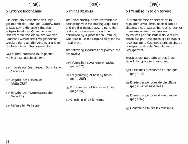
DE GB FR
68
5 Erstinbetriebnahme
Die erste Inbetriebnahme des Regel-gerätes mit der Heiz- und Brauchwasser-anlage sowie die ersten Eingabenentsprechend den Wünschen desBenutzers soll von einem anerkanntenFachhand-werksbetrieb vorgenommenwerden, der auch die Verantwortung fürdie Instal- lation übernommen hat.
Dabei sind insbesondere folgendeMaßnahmen durchzuführen:
☞ Hinweis auf Energiesparmöglichkeiten(Seite 12)
☞ Eingabe der Heizzeiten(Seite 26ff)
☞ Eingabe der Warmwasserzeiten(Seite 34)
☞ Prüfen aller Funktionen
5 Initial start-up
The initial start-up of the thermostat inconnection with the heating applianceand the first settings according to thecustomer preferences, should be performed by a professional installer,who also takes the responsibility for theinstallation.
The following measures are pointed outespecially:
☞ Information about energy saving(page 12)
☞ Programming of heating times(page 26ff)
☞ Programming of hot water times(page 34)
☞ Checking of all functions
5 Première mise en service
La première mise en service de larégulation avec l'installation d'eau de chauffage et d’eau sanitaire ainsi que lespremières entrées des donnéessouhaitées par l'utilisateur doivent être effectuées par l’entreprise spécialisée etreconnue qui a également pris en chargela responsabilité de l'installation de l’équipement.
Effectuer tout particulièrement, à cetégard, les opérations suivantes:
☞ Possibilités d'économies d'énergie(page 12)
☞ Entrée des périodes de chauffage(pages 26 et suivantes.)
☞ Entrée des périodes d'eau chaude(page 34)
☞ Contrôle de toutes les fonctions

69
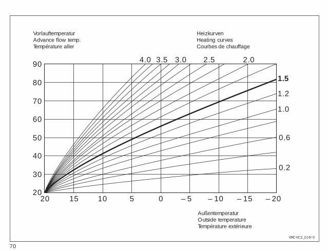
70
20 15 10 5 0 – 5 – 10 – 15 – 2020
30
40
50
60
70
80
90
0.2
0.6
1.0
1.2
1.5
2.02.53.03.54.0
VRC-VC2_019/0
VorlauftemperaturAdvance flow temp.Température aller
HeizkurvenHeating curvesCourbes de chauffage
AußentemperaturOutside temperatureTempérature extérieure
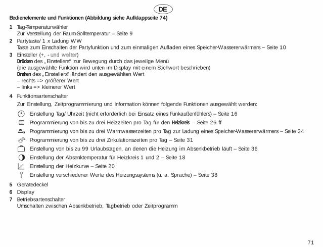
DE
71
Bedienelemente und Funktionen (Abbildung siehe Aufklappseite 74)
1 Tag-TemperaturwählerZur Verstellung der Raum-Solltemperatur – Seite 9
2 Partytaste/1 x Ladung WWTaste zum Einschalten der Partyfunktion und zum einmaligen Aufladen eines Speicher-Wassererwärmers – Seite 10
3 Einsteller (+, - uunndd wweeiitteerr)Drücken des „Einstellers“ zur Bewegung durch das jeweilge Menü(die ausgewählte Funktion wird unten im Display mit einem Stichwort beschrieben)Drehen des „Einstellers“ ändert den ausgewählten Wert– rechts => größerer Wert– links => kleinerer Wert
4 FunktionsartenschalterZur Einstellung, Zeitprogrammierung und Information können folgende Funktionen ausgewählt werden:
Einstellung Tag/Uhrzeit (nicht erforderlich bei Einsatz eines Funkaußenfühlers) – Seite 16
Programmierung von bis zu drei Heizzeiten pro Tag für den Heizkreis – Seite 26 ff
Programmierung von bis zu drei Warmwasserzeiten pro Tag zur Ladung eines Speicher-Wassererwärmers – Seite 34
Programmierung von bis zu drei Zirkulationszeiten pro Tag – Seite 31
Einstellung von bis zu 99 Urlaubstagen, an denen die Heizung im Absenkbetrieb läuft – Seite 36
Einstellung der Absenktemperatur für Heizkreis 1 und 2 – Seite 18
Einstellung der Heizkurve – Seite 20
Einstellung verschiedener Werte des Heizungssystems (u. a. Sprache) – Seite 38
5 Gerätedeckel6 Display7 Betriebsartenschalter
Umschalten zwischen Absenkbetrieb, Tagbetrieb oder Zeitprogramm
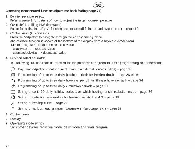
GB
72
Operating elements and functions (figure see back folding page 74)
1 Day temperature selectorRefer to page 9 for details of how to adjust the target room-temperature
2 Override/1 x filling HW (hot water)Button for activating „Party“ function and for one-off filling of tank water heater – page 10
3 Control knob (+, - onwardsPress the “adjuster“ to navigate through the corresponding menu(the selected function is shown at the bottom of the display with a keyword description)Turn the “adjuster“ to alter the selected value – clockwise => increased value – counterclockwise => decreased value
4 Function selection switchThe following functions can be selected for the purposes of adjustment, timer programming and information:
Day/time adjustment (not required if wireless external sensor is fitted) – page 16
Programming of up to three daily heating periods for heating circuit – page 26 et seq.
Programming of up to three daily hot-water period for filling a hot-water tank – page 34
Programming of up to three daily circulation periods – page 31
Setting of up to 99 daily holiday periods, on which heating runs in reduction mode – page 36
Setting of reduction temperature for heating circuits 1 and 2 – page 18
Setting of heating curve – page 20
Setting of various heating system parameters (language, etc.) – page 38
5 Control cover6 Display7 Operating mode switch
Switchover between reduction mode, daily mode and timer program
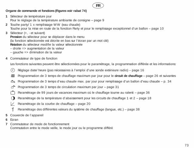
FR
73
Organe de commande et fonctions (Figures voir rabat 74)
1 Sélecteur de température jourPour le réglage de la température ambiante de consigne – page 9
2 Touche party/1 x remplissage WW (eau chaude)Touche pour la mise en route de la fonction Party et pour le remplissage exceptionnel d'un ballon – page 10
3 Sélecteur (+, - et suivant)Pression du sélecteur pour se déplacer dans le menu (la fonction sélectionnée est décrite en bas sur l'écran par un mot clé)Rotation du sélecteur modifie la valeur sélectionnée– droite => augmentation de la valeur– gauche => diminution de la valeur
4 Commutateur de type de fonction
Les fonctions suivantes peuvent être sélectionnées pour le paramétrage, la programmation différée et les informations:
Réglage date/heure (pas nécessaires à l'emploi d'une sonde extérieure radio) – page 16
Programmation de 3 temps de chauffage maximum par jour pour le circuit de chauffage – page 26 et suivantes
Programmation de 3 temps d'eau chaude max. par jour pour remplissage d'un ballon d'eau chaude – p. 34
Programmation de 3 temps de circulation maximum par jour – page 31
Paramétrage de 99 jours de vacances maximum où le chauffage tourne au ralenti – page 36
Paramétrage de la température d’abaissement pour les circuits de chauffage 1 et 2 – page 18
Paramétrage de la courbe de chauffage – page 20
Paramétrage des différentes valeurs du système de chauffage (langue, etc.) – page 38
5 Couvercle de l’appareil6 Ecran7 Commutateur de mode de fonctionnement
Commutation entre le mode veille, le mode jour ou le programme différé
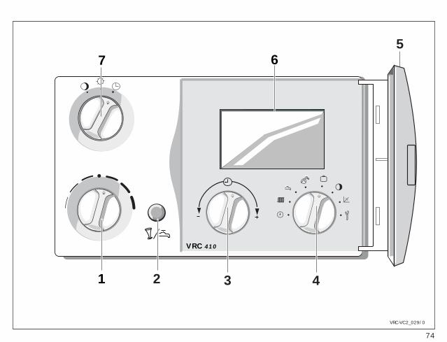
74
Party
Sa - 15°C
°C
VRC-VCC
+10
+2
+3
-1
-2
-3
21
7 65
3 4
VRC 410
VRC-VC2_029/0
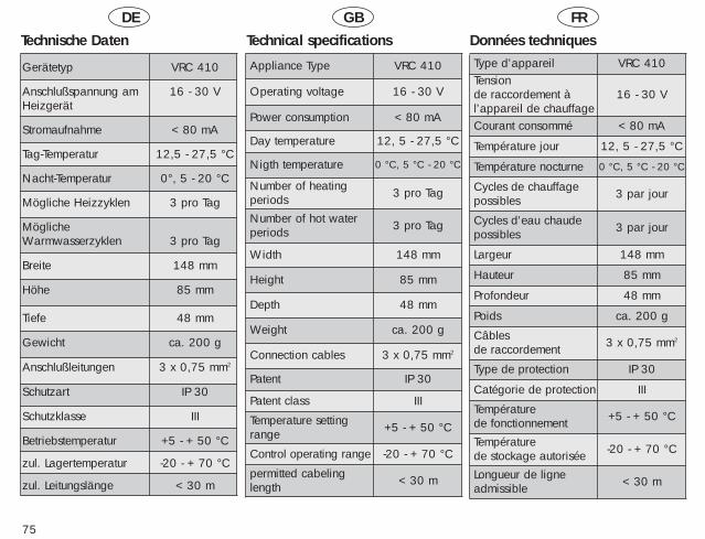
DE GB FR
75
Technische Daten
Gerätetyp VRC 410
Anschlußspannung am 16 - 30 VHeizgerät
Stromaufnahme < 80 mA
Tag-Temperatur 12,5 - 27,5 °C
Nacht-Temperatur 0°, 5 - 20 °C
Mögliche Heizzyklen 3 pro Tag
Mögliche Warmwasserzyklen 3 pro Tag
Breite 148 mm
Höhe 85 mm
Tiefe 48 mm
Gewicht ca. 200 g
Anschlußleitungen 3 x 0,75 mm2
Schutzart IP 30
Schutzklasse III
Betriebstemperatur +5 - + 50 °C
zul. Lagertemperatur -20 - + 70 °C
zul. Leitungslänge < 30 m
Technical specifications Données techniques
Appliance Type
Operating voltage
Power consumption
Day temperature
Nigth temperature
Number of heatingperiodsNumber of hot waterperiods
Width
Height
Depth
Weight
Connection cables
Patent
Patent class
Temperature settingrange
Control operating range
VRC 410
16 - 30 V
< 80 mA
12, 5 - 27,5 °C
0 °C, 5 °C - 20 °C
3 pro Tag
3 pro Tag
148 mm
85 mm
48 mm
ca. 200 g
3 x 0,75 mm2
IP 30
III
+5 - + 50 °C
-20 - + 70 °C
Type d’appareilTensionde raccordement à l’appareil de chauffageCourant consommé
Température jour
Température nocturne
Cycles de chauffagepossibles
Cycles d’eau chaudepossibles
Largeur
Hauteur
Profondeur
Poids
Câblesde raccordement
Type de protection
Catégorie de protection
Températurede fonctionnementTempératurede stockage autorisée
VRC 410
16 - 30 V
< 80 mA
12, 5 - 27,5 °C
0 °C, 5 °C - 20 °C
3 par jour
3 par jour
148 mm
85 mm
48 mm
ca. 200 g
3 x 0,75 mm2
IP 30
III
+5 - + 50 °C
-20 - + 70 °C
permitted cabelinglength < 30 m Longueur de ligne
admissible < 30 m
Vaillant GmbHBerghauser Straße 40 · 42859 Remscheid
Telefon: 0 21 91/18-0 · Telefax: 0 21 91/18-28 10http://www.vaillant.de · E-Mail: [email protected]
83 4
2 42
DE/
GB/F
R03
·04/
02 V
·Än
deru
ngen
vorb
ehalt
en -
Subje
ct to
alte
ratio
n - S
ous r
éserv
e de
mod
ificat
ions
Vaillant Ltd.Vaillant House · Medway City Estate
Rochester / Kent ME2 4EZFon: (1) 63 42 92 300 · Fax: (1) 63 42 90 166
Vaillant S.A.R.L.Europarc · 13, rue Claude Nicolas Ledoux
94045 Créteil CedexTél. (1) 45 13 51 00 · Fax (1) 45 13 51 02