Embed Size (px)
Citation preview
Modellieren
Modelling
Modelation soudure
Modellazione in cera
Modelado
_Betriebsanleitung
_Operating instructions
_Mode de fonctionnement
_Istruzioni sulfunzionamento
_Instrucciones de servicio
_Deutsch 04 - 06
_English 07 - 09
_Français 10 - 12
_Italiano 13 - 15
_Español 16 - 18
_EU-Declaration
of conformity 20
(
BL
BM
%
*
$
^
!
#
&
@
PRODUKTBESCHREIBUNGSmartwax duo ist ein Wachsmesser mit elektroni-scher Steuerung. Es bietet die Möglichkeit, zweiHandstücke anzuschließen, die getrennt vonein-ander regelbar sind.
Das Gerät ist für alle Modellier- und Aufwachs-arbeiten geeignet und erweist sich in Kombinationmit dem Waxjet auch in der Totalprothetik als un-schlagbar. Die kontinuierliche Wachszufuhr überden einmaligen Fördermechanismus des Waxjetermöglicht ein schnelles Auftragen von größerenWachsmengen und spart so Zeit.
Drei individuell programmierbare Temperaturenpro Handstück gewährleisten dem Techniker zu-dem höchsten Bedienkomfort.
Die Handstücke sind über verdrehsichere und tem-peraturunempfindliche Kabel mit dem Steuergerätverbunden und ermöglichen so ein angenehmesund ergonomisches Arbeiten.
Die Steckverbindung zwischen Handstückschaft undder fest mit dem Griffteil verbundenen Modellier-spitze macht den Austausch der Instrumente ein-fach und sicher – ohne ein Verbrennen der Finger.Gleichzeitig gewährleistet das Smartwax duo durchden Aufbau des Handstücks ein schnelles Aufheizender Instrumente. Eine wichtige Rolle spielt dabeiauch die gute Wärmeleitfähigkeit der Modellier-spitzen.
INBETRIEBNAHMEBitte überprüfen Sie das Gerät sofort nach demAuspacken auf eventuelle Transportschäden. Sollten
D
4
Transportschäden aufgetreten sein, diese bittesofort beim Lieferanten reklamieren. Das Gerätwird betriebsbereit ausgeliefert. Überprüfen Siebitte, ob die auf dem Netzgerät angegebeneSpannung mit der Netzspannung übereinstimmt.Falls Sie nicht sicher sind, welche Netzspannungin Ihrem Land verwendet wird, fragen Sie bitteim Elektrofachhandel nach.
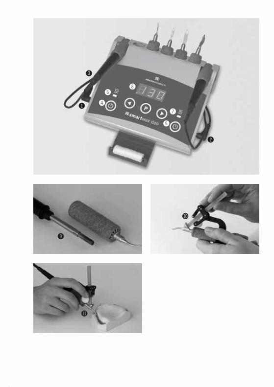
Zuerst das Handstückkabel an die AnschlussbuchseHandstück links (1) oder Handstück rechts (2) amSteuergehäuse anschließen. Dann das Kabel desNetzgerätes an den Netzgeräteanschluss (3) an-schließen und das Netzgerät mit der Netzspannungverbinden.
BEDIENUNGDie Handstücke werden separat über die Ein/Aus-Schalter (4 und 5) zugeschaltet. Nach dem Ein-schalten des ersten Handstücks zeigt das Display°C oder °F an. Während diese Anzeige blinkt, kannmit der Taste P zwischen °C und °F umgeschaltetwerden.
Während der Aufheizphase blinken die Kontroll-LED´s (6 und 7) - beim Erreichen der angewähltenTemperatur leuchten die Leuchtdioden dauerhaft.
Tastenkombination P und < oder P und >:_ Umschalten zwischen Handstück links und rechts._ P und < Handstück links ist aktiv_ P und > Handstück rechts ist aktiv
Der Kontroll-Leuchtpunkt (8) im Display zeigt dasHandstück an, für das die angezeigten Tempera-turen gelten bzw. das gerade aktiv regelbar ist.
Leuchtpunkt links unten:_ angezeigte Temperaturen gelten für das linke
Handstück_ linkes Handstück kann geregelt werden
Leuchtpunkt rechts unten:_ angezeigte Temperaturen gelten für das rechte
Handstück_ rechtes Handstück kann geregelt werden
WICHTIG: Auch das gerade nicht angewählteHandstück wird geheizt und das Instrument istheiß – die Kontroll-LED (6/ 7) leuchtet! Soll einHandstück nicht mehr geheizt werden, muss esüber den Ein/Aus-Schalter (4/ 5) komplett aus-geschaltet oder der Stecker des Handstückes ausder Anschlussbuchse gezogen werden!
Tasten < und >:_ Temperatur senken (<)_ Temperatur erhöhen (>)
! Anschlussbuchse Handstück links
@ Anschlussbuchse Handstück rechts
# Netzgerätanschluss
$ Ein/Aus-Schalter Handstück links
% Ein/Aus-Schalter Handstück rechts
^ Kontroll-LED für Betriebszustand Handstück
links
& Kontroll-LED für Betriebszustand Handstück
rechts
* Kontroll-Leuchtpunkt aktives Handstück
( Heizelement
BL Transportrollen Waxjet
BM Antriebsrolle Waxjet
BETRIEBSANLEITUNGOriginal-Betriebsanleitung
D
5
Kurzes Drücken der Tasten ändert die Temperaturum 1 °C. Bei längerdauerndem Druck steigt (bzw.fällt) die Temperatur zuerst langsam, dann zu-nehmend schneller (Schnelllauf).
Taste P:_ Programmtaste_ Umschalten der Temperaturanzeige von ° C in ° F
nach dem Einschalten des ersten Handstückes._ Auswählen der programmierten Temperaturen
P1 – P3 je Handstück (fortlaufend).
Werksseitig ist das Gerät mit folgenden Tem-peraturen programmiert (für beide Handstücke):P1 70 °C (158 °F)P2 100 °C (212 °F)P3 130 °C (266 °F)
Temperatureinstellung speichern:Auf den Programmplätzen P1 – P3 kann auchjeweils eine individuelle Temperatur abgespeichertwerden:Den Programmplatz der verändert werden sollauswählen (P1 – P3 über die Taste P).Dann mit den Tasten < oder > die gewünschteTemperatur ansteuern. Anschließend die Taste Pdrücken und für etwa 3 Sekunden gedrückt halten,bis die Programmanzeige blinkt. Damit ist dieTemperatur gespeichert und kann zukünftig überdie Taste P auf dem entsprechenden Programm-platz angewählt werden.
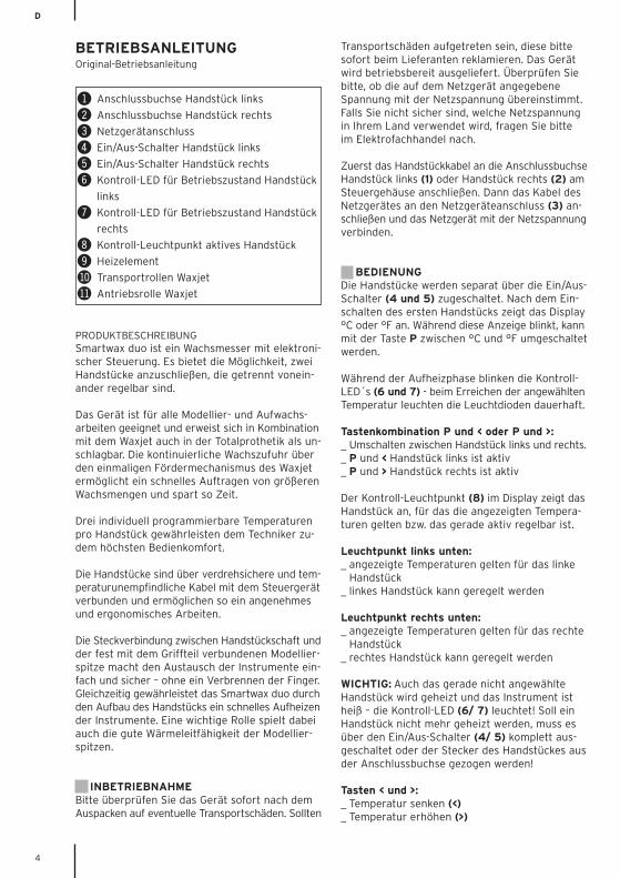
Wechseln der Sonde:Zum Sondenwechsel den kompletten Korkgriff nachvorne in Sondenrichtung abziehen. Die Sondensind fest mit dem Korkgriff verbunden, dadurchwird automatisch ein Verdrehen der Sonde beimModellieren verhindert.Zum Aufsetzen eines anderen Modellierinstrumentsden Griff bis zum hörbaren Einrasten auf dasHandstück aufstecken.An der Rückseite des Steuergerätes befinden sichdie Ablagen für zusätzliche Modellierspitzen.
WICHTIG: Das Heizelement (9) liegt nach demAbziehen des Korkgriffes frei. Heizelement nichtberühren! Verbrennungsgefahr!
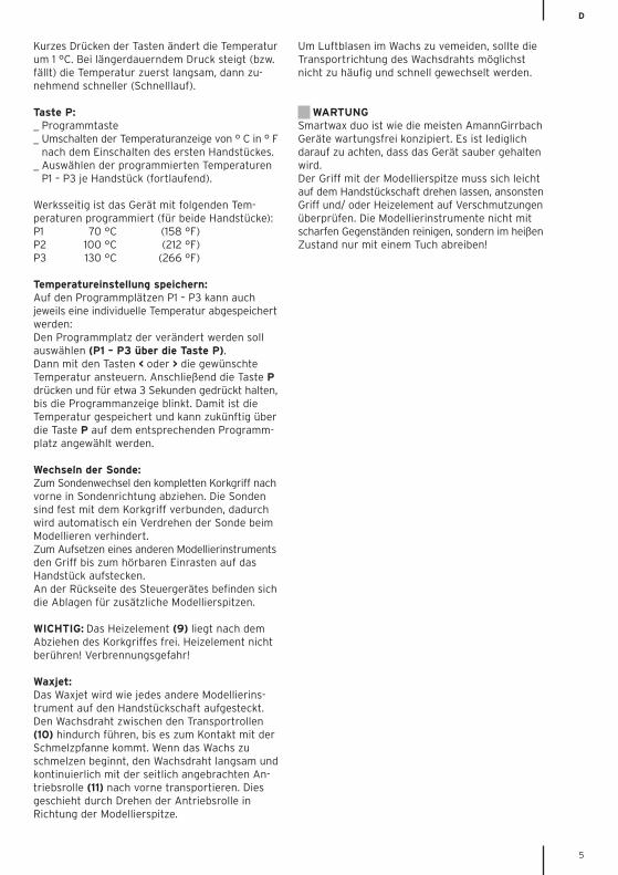
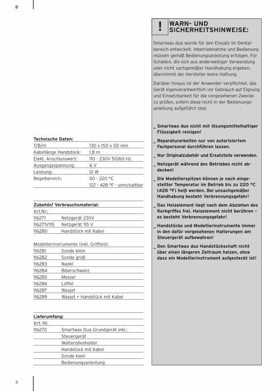
Waxjet:Das Waxjet wird wie jedes andere Modellierins-trument auf den Handstückschaft aufgesteckt.Den Wachsdraht zwischen den Transportrollen(10) hindurch führen, bis es zum Kontakt mit derSchmelzpfanne kommt. Wenn das Wachs zuschmelzen beginnt, den Wachsdraht langsam undkontinuierlich mit der seitlich angebrachten An-triebsrolle (11) nach vorne transportieren. Diesgeschieht durch Drehen der Antriebsrolle inRichtung der Modellierspitze.
Um Luftblasen im Wachs zu vemeiden, sollte dieTransportrichtung des Wachsdrahts möglichstnicht zu häufig und schnell gewechselt werden.
WARTUNGSmartwax duo ist wie die meisten AmannGirrbachGeräte wartungsfrei konzipiert. Es ist lediglichdarauf zu achten, dass das Gerät sauber gehaltenwird.Der Griff mit der Modellierspitze muss sich leichtauf dem Handstückschaft drehen lassen, ansonstenGriff und/ oder Heizelement auf Verschmutzungenüberprüfen. Die Modellierinstrumente nicht mitscharfen Gegenständen reinigen, sondern im heißenZustand nur mit einem Tuch abreiben!
D
6
Technische Daten:
T/B/H: 130 x 150 x 50 mm
Kabellänge Handstück: 1,8 m
Elekt. Anschlusswert: 110 - 230V 50/60 Hz
Ausgangsspannung: 6 V
Leistung: 12 W
Regelbereich: 50 - 220 °C
122 - 428 °F - umschaltbar
Zubehör/ Verbrauchsmaterial:
Art.Nr.:
116271 Netzgerät 230V
116271V115 Netzgerät 115 V
116280 Handstück mit Kabel
Modellierinstrumente (inkl. Griffteil):
116281 Sonde klein
116282 Sonde groß
116283 Nadel
116284 Biberschwanz
116285 Messer
116286 Löffel
116287 Waxjet
116289 Waxjet + Handstück mit Kabel
Lieferumfang:
Art.-Nr.
116270 Smartwax Duo Grundgerät inkl.:
Steuergerät
Watterollenhalter
Handstück mit Kabel
Sonde klein
Bedienungsanleitung
WARN- UNDSICHERHEITSHINWEISE:
Smartwax duo wurde für den Einsatz im Dental-bereich entwickelt. Inbetriebnahme und Bedienungmüssen gemäß Bedienungsanleitung erfolgen. FürSchäden, die sich aus anderweitiger Verwendungoder nicht sachgemäßer Handhabung ergeben,übernimmt der Hersteller keine Haftung.
Darüber hinaus ist der Anwender verpflichtet, dasGerät eigenverantwortlich vor Gebrauch auf Eignungund Einsetzbarkeit für die vorgesehenen Zweckezu prüfen, sofern diese nicht in der Bedienungs-anleitung aufgeführt sind.
_ Smartwax duo nicht mit lösungsmittelhaltiger Flüssigkeit reinigen!
_ Reparaturarbeiten nur von autorisiertem Fachpersonal durchführen lassen.
_ Nur Originalzubehör und Ersatzteile verwenden.
_ Netzgerät während des Betriebes nicht ab-decken!
_ Die Modellierspitzen können je nach einge-stellter Temperatur im Betrieb bis zu 220 °C (428 °F) heiß werden. Bei unsachgemäßer Handhabung besteht Verbrennungsgefahr!
_ Das Heizelement liegt nach dem Abziehen des Korkgriffes frei. Heizelement nicht berühren – es besteht Verbrennungsgefahr!
_ Handstücke und Modellierinstrumente immer in den dafür vorgesehenen Halterungen am Steuergerät aufbewahren!
_ Den Smartwax duo Handstückschaft nicht über einen längeren Zeitraum heizen, ohne dass ein Modellierinstrument aufgesteckt ist!
!
GB
7
PRODUCT DESCRIPTIONSmartwax duo is an electronically controlled waxknife with the possibility to connect two handpiecesthat can be operated separately.
This unit is suitable for all kinds of modeling andwax-up work and is unbeatable in combination withthe Waxjet when making full dentures. The con-tinuous wax supply via the unique feeding mech-anism of the Waxjet allows the dental technicianto quickly apply a big amount of wax, which helpsto save time.
Each handpiece can individually be set to threedifferent temperatures. This means utmost usercomfort for the dental technician.
A twist-free and heat-resistant cord connects thehandpieces with the control unit and ensurescomfortable and ergonomic work.
The plug-in connector between the handpieceshank and the handle with firmly fixed modelingtip offers easy and safe exchange of the instru-ments – without burning the fingers. At the sametime, the Smartwax duo handpiece heats up theinstruments very quickly thanks to the specialdesign of the handpiece and to the good heatconductivity of the modeling tip.
START-UPPlease check immediately after unpacking if theunit shows transport damages. If so, please informthe supplier promptly. After unpacking, the unit
is ready for operation. Please check if the voltageof the mains adaptor corresponds to the localmains voltage. If you are uncertain about themains voltage used in your country, we recom-mend addressing to the electric or electronictrade.
At first, plug in the handpiece cord at the connec-tor socket of the left handpiece (1) or of the righthandpiece (2) at the housing of the unit. Then,connect the cable of the mains adaptor to themains connection (3) and to the mains voltage.
OPERATIONEach handpiece is switched on separately bypressing the according On/Off switch (4 or 5).After switching on the first handpiece, the displayindicates °C or °F. As long as this notice is flashing,you can choose between °C and °F with the pro-gram key P.
While heating up, the pilot LEDs (6 and 7) areflashing, but when the selected temperature isreached, the LEDs light permanently.
Shortcuts P < or P >:_ These shortcuts are used to switch between
the left and the right handpiece._ With P < you activate the left handpiece._ With P > you activate the right handpiece.
The light spot (8) in the display shows which hand-piece is activated at the moment and to whichhandpiece the temperatures indicated belong.
Light spot at left:_ temperatures indicated in the display belong to
the left handpiece_ left handpiece can be controlled
Light spot at right:_ temperatures indicated in the display belong to
the right handpiece_ right handpiece can be controlled
IMPORTANT: If the pilot LED (6 / 7) is lit, alsothe other handpiece is heated and the instrumentis hot! Therefore, if you only work with one hand-piece, either completely switch off the other hand-piece at the On/Off switch (4 / 5) or pull the plugof the handpiece cord out of the connector socket!
Keys < and >:_ With < you lower the temperature._ With > you increase the temperature.A short push on either one of these keys changesthe temperature by 1 °C. If you push longer, thetemperature first drops or increases slowly, andthen becomes faster (fast mode).
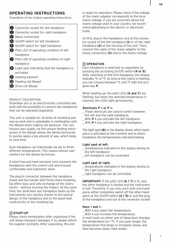
! Connector socket for left handpiece
@ Connector socket for right handpiece
# Mains connection
$ On/Off switch for left handpiece
% On/Off switch for right handpiece
^ Pilot LED of operating condition of left
handpiece
& Pilot LED of operating condition of right
handpiece
* Light spot indicating that the handpiece is
activated
( Heating element
BL Feeding roll Waxjet
BM Drive roll Waxjet
OPERATING INSTRUCTIONSTranslation of the original operating instructions
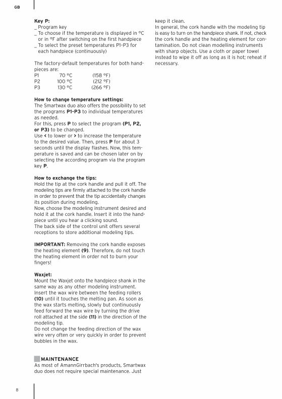
Key P:_ Program key_ To choose if the temperature is displayed in °C
or in °F after switching on the first handpiece_ To select the preset temperatures P1–P3 for
each handpiece (continuously)
The factory-default temperatures for both hand-pieces are:P1 70 °C (158 °F)P2 100 °C (212 °F)P3 130 °C (266 °F)
How to change temperature settings:The Smartwax duo also offers the possibility to setthe programs P1-P3 to individual temperaturesas needed.For this, press P to select the program (P1, P2,or P3) to be changed.Use < to lower or > to increase the temperatureto the desired value. Then, press P for about 3seconds until the display flashes. Now, this tem-perature is saved and can be chosen later on byselecting the according program via the programkey P.
How to exchange the tips:Hold the tip at the cork handle and pull it off. Themodeling tips are firmly attached to the cork handlein order to prevent that the tip accidentally changesits position during modeling.Now, choose the modeling instrument desired andhold it at the cork handle. Insert it into the hand-piece until you hear a clicking sound.The back side of the control unit offers severalreceptions to store additional modeling tips.
IMPORTANT: Removing the cork handle exposesthe heating element (9). Therefore, do not touchthe heating element in order not to burn yourfingers!
Waxjet:Mount the Waxjet onto the handpiece shank in thesame way as any other modeling instrument.Insert the wax wire between the feeding rollers(10) until it touches the melting pan. As soon asthe wax starts melting, slowly but continuouslyfeed forward the wax wire by turning the driveroll attached at the side (11) in the direction of themodeling tip.Do not change the feeding direction of the waxwire very often or very quickly in order to preventbubbles in the wax.
MAINTENANCEAs most of AmannGirrbach's products, Smartwaxduo does not require special maintenance. Just
keep it clean.In general, the cork handle with the modeling tipis easy to turn on the handpiece shank. If not, checkthe cork handle and the heating element for con-tamination. Do not clean modelling instrumentswith sharp objects. Use a cloth or paper towelinstead to wipe it off as long as it is hot; reheat ifnecessary.
GB
8
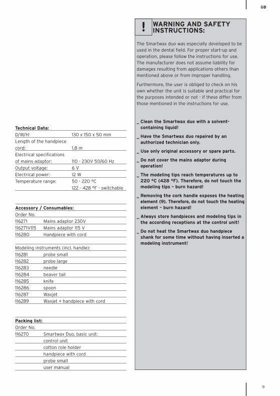
Technical Data:
D/W/H: 130 x 150 x 50 mm
Length of the handpiece
cord: 1,8 m
Electrical specifications
of mains adaptor: 110 - 230V 50/60 Hz
Output voltage: 6 V
Electrical power: 12 W
Temperature range: 50 - 220 °C
122 - 428 °F - switchable
Accessory / Consumables:
Order No.
116271 Mains adaptor 230V
116271V115 Mains adaptor 115 V
116280 Handpiece with cord
Modeling instruments (incl. handle):
116281 probe small
116282 probe large
116283 needle
116284 beaver tail
116285 knife
116286 spoon
116287 Waxjet
116289 Waxjet + handpiece with cord
Packing list:
Order No.
116270 Smartwax Duo, basic unit:
control unit
cotton role holder
handpiece with cord
probe small
user manual
WARNING AND SAFETYINSTRUCTIONS:
The Smartwax duo was especially developed to beused in the dental field. For proper start-up andoperation, please follow the instructions for use.The manufacturer does not assume liability fordamages resulting from applications others thanmentioned above or from improper handling.
Furthermore, the user is obliged to check on hisown whether the unit is suitable and practical forthe purposes intended or not - if these differ fromthose mentioned in the instructions for use.
_ Clean the Smartwax duo with a solvent-containing liquid!
_ Have the Smartwax duo repaired by an authorized technician only.
_ Use only original accessory or spare parts.
_ Do not cover the mains adaptor during operation!
_ The modeling tips reach temperatures up to 220 °C (428 °F). Therefore, do not touch the modeling tips – burn hazard!
_ Removing the cork handle exposes the heatingelement (9). Therefore, do not touch the heatingelement – burn hazard!
_ Always store handpieces and modeling tips in the according receptions at the control unit!
_ Do not heat the Smartwax duo handpiece shank for some time without having inserted amodeling instrument!
!
GB
9
F
10
DESCRIPTION DU PRODUITLe Smartwax duo est une spatule à cire chauffante,équipée d’un système de commande électronique.Vous pouvez brancher deux pièces à main sur cetappareil et les régler séparément. Cet appareil convient pour tous les travaux demodelage en cire et, en prothèse complète, con-stitue avec le Waxjet le tandem idéal.L’alimentation continue en cire via le remarquablesystème de transport du Waxjet permet de déposerrapidement de grosses quantités de cire, ce quivous fera gagner du temps.
L’utilisateur ayant pour chaque pièce à main lechoix entre trois températures différentes (pro-grammables), il bénéficie d’un confort d’utilisationoptimal.
Les deux pièces à main sont reliées à la commandevia des câbles antitorsion et résistant aux hautestempératures. Ce qui vous permet de travailler defaçon ergonomique et dans le confort. Le raccord situé entre la tige de la pièce de la mainet l’insert de modelage solidaire du manche faitque changer d’insert est facile et rapide, sans risquede se brûler les doigts.De par la conception des deux pièces à main, etdu fait aussi de la bonne conductivité thermiquedes inserts, ces derniers sont vite chauffés par leSmartwax duo.
MISE EN SERVICEAprès avoir déballé l’appareil, vérifiez aussitôtqu’il n’a pas été abîmé pendant le transport. S’il aété abîmé, faites aussitôt une réclamation auprèsde votre fournisseur. Cet appareil est livré prêt àl’emploi. Veuillez vérifier que la tension de votrecourant de secteur correspond bien à celle indiquéesur l’appareil. Si vous avez un doute quant à latension du courant de secteur utilisé dans le paysoù vous vous trouvez, demandez sur place à unvendeur électricien.
Commencez par brancher le cordon de la pièce àmain sur la prise correspondante (prise de gauchepour la prise à main côté gauche (1), prise droitepour la pièce à main côté droit (2)) puis branchezle câble de l’unité d’alimentation sur la prise (3)et branchez ensuite cette unité d’alimentationsur une prise de courant (courant de secteur).
UTILISATION DE L’APPAREILLes deux pièces à main ont chacune leur inter-rupteur Marche/Arrêt (4 et 5). Après avoir mis enmarche la première pièce à main, l’afficheur vousaffiche la température (°C ou°F). Tant que cetaffichage clignote, vous pouvez passer de °C à °Fet réciproquement.
Pendant la phase de chauffe les voyants LED (6et 7) clignotent. Quand la température présélec-tionnée sera atteinte, ils resteront allumés.
Les combinaisons de touches « P et < « et « P et > » :_ Elles servent à activer les pièces à main comme
suit_ utilisez la combinaison « P et < » pour activer
la pièce à main de gauche_ et la combinaison « P et > » pour activer la
pièce à main de droite
Le point lumineux (8) présent sur l’afficheur vousindique à quelle pièce à main correspond la tem-pérature affichée, et quelle est la pièce à mainactuellement active et réglable.
Point lumineux en bas à gauche :_ la température affichée correspond à la pièce à
main située à gauche(Pièce à main réglable : celle de gauche).
Point lumineux en bas à droite :_ la température affichée correspond à la pièce à
main située à droite(Pièce à main réglable : celle de droite).
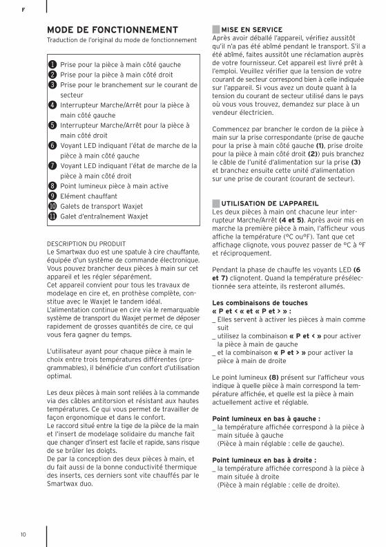
! Prise pour la pièce à main côté gauche
@ Prise pour la pièce à main côté droit
# Prise pour le branchement sur le courant de
secteur
$ Interrupteur Marche/Arrêt pour la pièce à
main côté gauche
% Interrupteur Marche/Arrêt pour la pièce à
main côté droit
^ Voyant LED indiquant l’état de marche de la
pièce à main côté gauche
& Voyant LED indiquant l’état de marche de la
pièce à main côté droit
* Point lumineux pièce à main active
( Elément chauffant
BL Galets de transport Waxjet
BM Galet d’entraînement Waxjet
MODE DE FONCTIONNEMENTTraduction de l’original du mode de fonctionnement
F
11
IMPORTANT : La pièce à main non sélectionnéesera chauffée elle aussi, de même que son insert(voyants LED 6 et 7 allumés !) Si vous voulez quela pièce à main non utilisée ne soit pas chauffée,l’éteindre complètement en actionnant son inter-rupteur Marche/Arrêt ou la débrancher de l’appareil !
Les touches « < » et » > » :_ Pour abaisser la température, utilisez la touche <_ Et pour l’augmenter la touche >Si vous appuyez brièvement sur l’une ou l’autrede ces deux touches, la température changera de1 °C. Si vous appuyez plus longtemps, la tempéra-ture diminuera/augmentera d’abord lentement puisde plus en plus vite (défilement rapide).
La touche « P »:_ Touche de programmation_ Commutation affichage température °C/°F
après mise en marche de la première pièce à main.
_ Sélection des températures programmées (P1 – P3) pour chacune des pièces à main (sélection dans l’ordre croissant).
Les températures qui ont été programmées à l’u-sine (pour les deux pièces à main) sont les sui-vantes :P1 70°C (158°F)P2 100°C (212°F)P3 130°C (266°F)
Mémorisation de la température de réglage:Vous pouvez, aux emplacements mémoire P1 àP3, mémoriser la température de réglage de votrechoix en procédant comme suit : Sélectionnez, avec la touche P, l’emplacementmémoire concerné (P1, P2 ou P3).Ensuite, avec la touche < ou la touche >, entrez latempérature souhaitée puis appuyez pendant 3secondes environ sur la touche P, c'est-à-direjusqu’à ce que l’affichage programme clignote.Dès qu’il clignote, cela veut dire que la tempéra-ture entrée a bien été mémorisée et que vouspourrez donc ultérieurement la sélectionner avecla touche P (pour l’emplacement mémoire cor-respondant).
Changement d’insert:Pour changer d’insert, tirez complètement l’em-bout en liège vers l’avant c'est-à-dire vers l’insert.L’insert étant solidaire de cet embout, il n’y a aucunrisque que l’insert tourne sur lui-même pendantle modelage. Pour monter le nouvel insert, pousser son emboutsur la pièce à main jusqu’à ce vous l’entendiezs’enclencher.Vous avez au dos de l’appareil des compartimentspour ranger les inserts.
IMPORTANT: L’élément chauffant (9) étant àdécouvert quand on retire l’embout en liège, nepas le toucher car vous vous brûleriez ! Waxjet:Comme tout appareil de modelage, le Waxjet sebranche sur la tige de la pièce à main. Faire cir-culer le fil de cire entre les galets de transport(10) jusqu’à ce qu’il soit en contact avec la cuvettechauffante. Dès que la cire commence à fondre,faire avancer le fil de cire doucement, sans à-coups,à l’aide du galet de transport 11, situé sur le côté.Pour cela, faire tourner le galet d’entraînementen direction de l’insert. Afin d’éviter l’incorporationde bulles d’air à la cire, il est recommandé de nepas changer trop souvent ni brusquement ladirection de transport du fil de cire.
ENTRETIENComme la plupart des appareils AmannGirrbach,celui-ci est également sans entretien. Vous devezsimplement veiller à ce qu’il soit toujours propre. Vérifiez aussi que l’embout en liège monté sur latige de la pièce à main, et sur lequel est fixé l’insert,ne soit pas grippé. S’il l’est, regarder s’il n’y a pasde saletés sur l’embout et/ou l’élément chauffant.Ne pas nettoyer ces instruments à sculpter avecdes objets tranchants. Pour les nettoyer, simple-ment les essuyer - à chaud - avec un chiffon.
F
12
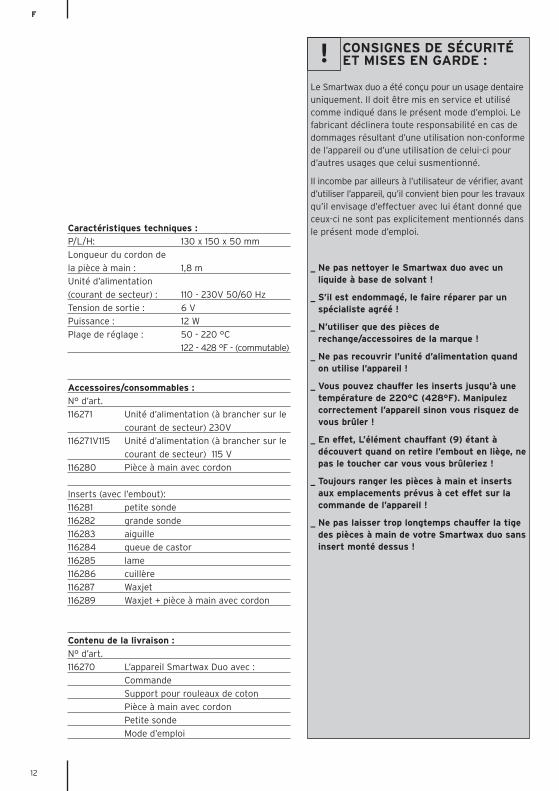
Caractéristiques techniques :
P/L/H: 130 x 150 x 50 mm
Longueur du cordon de
la pièce à main : 1,8 m
Unité d’alimentation
(courant de secteur) : 110 - 230V 50/60 Hz
Tension de sortie : 6 V
Puissance : 12 W
Plage de réglage : 50 - 220 °C
122 - 428 °F - (commutable)
Accessoires/consommables :
N° d’art.
116271 Unité d’alimentation (à brancher sur le
courant de secteur) 230V
116271V115 Unité d’alimentation (à brancher sur le
courant de secteur) 115 V
116280 Pièce à main avec cordon
Inserts (avec l’embout):
116281 petite sonde
116282 grande sonde
116283 aiguille
116284 queue de castor
116285 lame
116286 cuillère
116287 Waxjet
116289 Waxjet + pièce à main avec cordon
Contenu de la livraison :
N° d’art.
116270 L’appareil Smartwax Duo avec :
Commande
Support pour rouleaux de coton
Pièce à main avec cordon
Petite sonde
Mode d’emploi
CONSIGNES DE SÉCURITÉET MISES EN GARDE :
Le Smartwax duo a été conçu pour un usage dentaireuniquement. Il doit être mis en service et utilisécomme indiqué dans le présent mode d’emploi. Lefabricant déclinera toute responsabilité en cas dedommages résultant d’une utilisation non-conformede l’appareil ou d’une utilisation de celui-ci pourd’autres usages que celui susmentionné.
Il incombe par ailleurs à l’utilisateur de vérifier, avantd’utiliser l’appareil, qu’il convient bien pour les travauxqu’il envisage d’effectuer avec lui étant donné queceux-ci ne sont pas explicitement mentionnés dansle présent mode d’emploi.
_ Ne pas nettoyer le Smartwax duo avec un liquide à base de solvant !
_ S’il est endommagé, le faire réparer par un spécialiste agréé !
_ N’utiliser que des pièces de rechange/accessoires de la marque !
_ Ne pas recouvrir l’unité d’alimentation quand on utilise l’appareil !
_ Vous pouvez chauffer les inserts jusqu’à une température de 220°C (428°F). Manipulez correctement l’appareil sinon vous risquez de vous brûler !
_ En effet, L’élément chauffant (9) étant à découvert quand on retire l’embout en liège, nepas le toucher car vous vous brûleriez !
_ Toujours ranger les pièces à main et inserts aux emplacements prévus à cet effet sur la commande de l’appareil !
_ Ne pas laisser trop longtemps chauffer la tige des pièces à main de votre Smartwax duo sansinsert monté dessus !
!
I
13
DESCRIZIONE DEL PRODOTTOSmartwax duo è una spatola per cera a comandoelettronico, utilizzabile con due manipoli regolabiliseparatamente. L’apparecchio può essere usato pertutti i lavori di modellazione e ceratura. Se usatoinsieme al Waxjet è eccezionale anche per i lavoridi protesi totale. Il continuo apporto di cera attra-verso il meccanismo di trasporto del Waxjet con-sente un‘applicazione veloce di maggiori quantitàdi cera ed un risparmio di tempo.
Tre temperature individualmente programmabiliper ogni manipolo assicurano il massimo comfortdi utilizzo.
I manipoli sono collegati all’unità di comando condei cavi antitorsione e termoresistenti per consentireun lavoro ergonomico. Grazie al collegamento adinnesto tra il gambo del manipolo e la punta dimodellazione, il cambio delle punte avviene in modofacile e sicuro, senza bruciature alle dita. Inoltre,la struttura del manipolo Smartwax duo assicurail riscaldamento rapido delle punte di modellazione,che si contraddistinguono per la loro ottima con-duttività termica.
MESSA IN FUNZIONEDopo aver tolto l’imballo, assicurarsi immediata-mente che non vi siano stati danneggiamentidurante il trasporto. In caso di danni dovuti altrasporto, rivolgersi subito al fornitore. L’apparecchiofornito è pronto per la messa in funzione. Assicurarsiche il voltaggio indicato sull‘alimentatore corrispon-da alla tensione di rete. Se non siete sicuri delvoltaggio disponibile nel vostro paese, informatevipresso il vostro elettricista.
Dapprima inserire il cavo nella presa del manipolosinistro (1) o destro (2) sull’unità di comando.Dopodiché, inserire il cavo dell’alimentatorenell‘apposita presa (3) e collegare l’alimentatorealla tensione di rete.
UTILIZZOI manipoli si accendono separatamente azionandol’apposito interruttore (4 e 5). Dopo l’azionamentodel primo manipolo, sul display (8) lampeggia °Coppure°F. Con il tasto P scegliere l’unità richiesta.
Durante la fase di riscaldamento lampeggiano iLED di controllo (3 e 4). A raggiungimento dellatemperatura richiesta i diodi rimangono accesisenza lampeggiare.
Combinazione di tasti P e < oppure P e >:_ cambio tra manipolo sinistro e destro_ P e < attiva il manipolo sinistro_ P e > attiva il manipolo destro
Il punto luminoso di controllo (8) indica a qualemanipolo corrispondono le temperature indicatecioè quale manipolo è attivamente regolabile inquel momento.
Punto luminoso in basso a sinistra:_ le temperature indicate corrispondono al mani-
polo sinistro_ è possibile regolare il manipolo sinistro
Punto luminoso in basso a destra:_ le temperature indicate corrispondono al mani-
polo destro_ è possibile regolare il manipolo destro
IMPORTANTE: Viene riscaldata anche la punta delmanipolo attualmente non selezionato – il LED dicontrollo (6/7) è acceso! Per spegnere completa-mente il riscaldamento di un manipolo è necessa-rio azionare l’interruttore on/off (4/5) oppureestrarre il cavo del manipolo dalla presa!
Tasti < e >:_ abbassare la temperatura (<)_ aumentare la temperatura (>)Premendo brevemente i tasti, la temperaturasale/scende di 1 °C. Tenendo premuti i tasti, latemperatura sale/scende prima lentamente equindi sempre più velocemente.
Tasto P:_ tasto programma_ cambio dell’indicazione della temperatura da ° C
a ° F dopo l’azionamento del primo manipolo_ selezione delle temperature programmate
P1 – P3 per manipolo (continua).
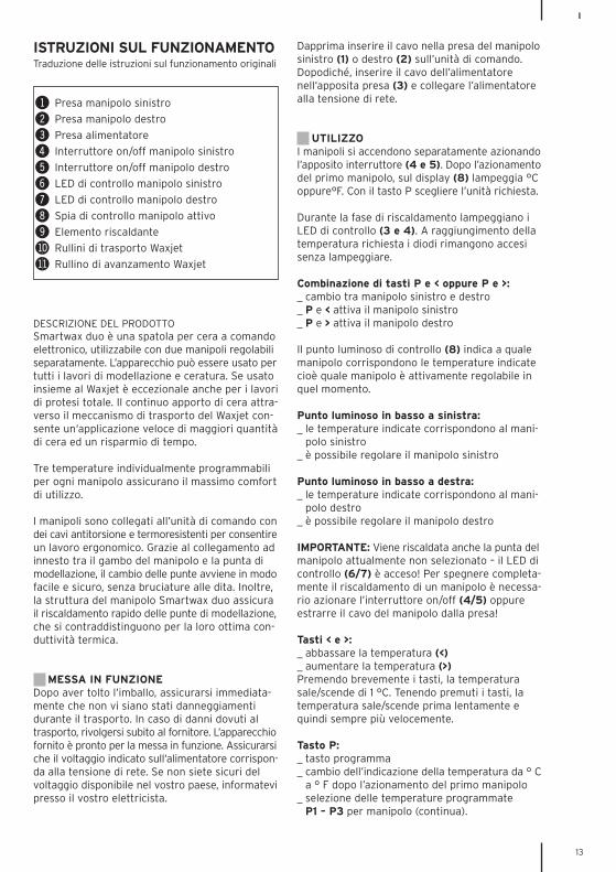
! Presa manipolo sinistro
@ Presa manipolo destro
# Presa alimentatore
$ Interruttore on/off manipolo sinistro
% Interruttore on/off manipolo destro
^ LED di controllo manipolo sinistro
& LED di controllo manipolo destro
* Spia di controllo manipolo attivo
( Elemento riscaldante
BL Rullini di trasporto Waxjet
BM Rullino di avanzamento Waxjet
ISTRUZIONI SUL FUNZIONAMENTOTraduzione delle istruzioni sul funzionamento originali
I
14
L’apparecchio è stato programmato dal produttorecon le seguenti temperature (per entrambi i mani-poli):P1 70 °C (158 °F)P2 100 °C (212 °F)P3 130 °C (266 °F)
Memorizzazione delle temperature impostate:È possibile la memorizzazione di temperatureindividuali nei programmi P1 – P3:Selezionare il programma da modificare (P1 – P3con il tasto P). Dopodiché, con i tasti < o > impos-tare la temperatura desiderata. Premere quindi iltasto P e tenerlo premuto per 3 secondi ca. finchéil programma inizia a lampeggiare. In questo modola temperatura è memorizzata e potrà essererichiamata mediante l‘apposito programma pre-mendo il tasto P.
Cambio della punta:Per cambiare la punta, sfilare l’intera impugnaturain sughero in avanti in direzione della punta. Lepunte sono saldamente unite all’impugnatura insughero per evitare lo spostamento automaticodella punta durante la modellazione. Per l’appli-cazione di un’altra punta, inserire l’impugnaturasul manipolo fino all’innesto. Sul retro dell’unitàdi comando si trovano i supporti per altre puntedi modellazione.
IMPORTANTE: Dopo aver sfilato l’impugnatura insughero, l’elemento riscaldante (9) è scoperto. Nontoccare l’elemento riscaldante! Pericolo di bruciature!
Waxjet:Come tutte le punte di modellazione, il Waxjet vieneapplicato sul gambo del manipolo. Introdurre il filoin cera tra i rullini di trasporto (10) finché entra incontatto con il fusore. Non appena la cera inizia asciogliersi, fare avanzare il filo in cera in modolento e graduale girando il rullino di avanzamento(11) in direzione della punta di modellazione. Perevitare la formazione di bolle di aria nella cera, siconsiglia di non cambiare la direzione di trasportodel filo troppo velocemente e frequentemente.
MANUTENZIONECome la maggior parte delle apparecchiatureAmann, Smartwax duo non richiede manutenzione,ma è importante tenerlo pulito. L’impugnatura conla punta di modellazione deve essere facilmentegirevole sul gambo del manipolo, altrimenti ènecessario assicurarsi che l’impugnatura e/o l’e-lemento riscaldante siano perfettamente puliti.Non pulire le punte di modellazione con strumentiaffilati. Pulire le punte ancora calde strofinandolecon un panno!
I
15
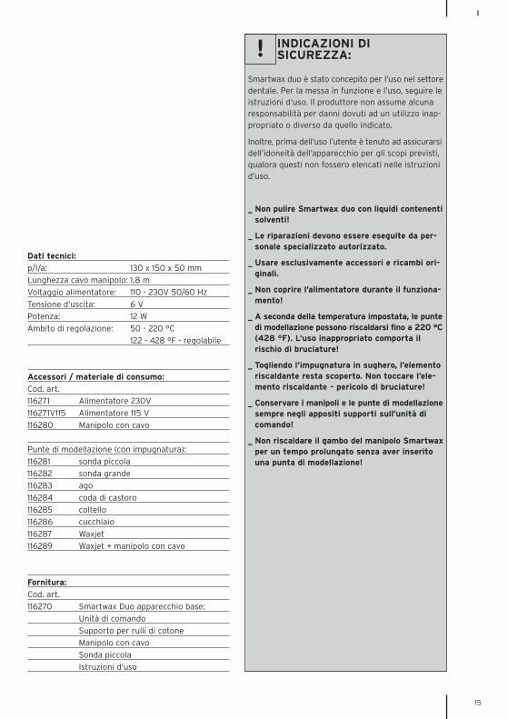
Dati tecnici:
p/l/a: 130 x 150 x 50 mm
Lunghezza cavo manipolo: 1,8 m
Voltaggio alimentatore: 110 - 230V 50/60 Hz
Tensione d‘uscita: 6 V
Potenza: 12 W
Ambito di regolazione: 50 - 220 °C
122 - 428 °F - regolabile
Accessori / materiale di consumo:
Cod. art.
116271 Alimentatore 230V
116271V115 Alimentatore 115 V
116280 Manipolo con cavo
Punte di modellazione (con impugnatura):
116281 sonda piccola
116282 sonda grande
116283 ago
116284 coda di castoro
116285 coltello
116286 cucchiaio
116287 Waxjet
116289 Waxjet + manipolo con cavo
Fornitura:
Cod. art.
116270 Smartwax Duo apparecchio base:
Unità di comando
Supporto per rulli di cotone
Manipolo con cavo
Sonda piccola
Istruzioni d’uso
INDICAZIONI DISICUREZZA:
Smartwax duo è stato concepito per l’uso nel settoredentale. Per la messa in funzione e l’uso, seguire leistruzioni d‘uso. Il produttore non assume alcunaresponsabilità per danni dovuti ad un utilizzo inap-propriato o diverso da quello indicato.
Inoltre, prima dell‘uso l’utente è tenuto ad assicurarsidell’idoneità dell’apparecchio per gli scopi previsti,qualora questi non fossero elencati nelle istruzionid’uso.
_ Non pulire Smartwax duo con liquidi contenentisolventi!
_ Le riparazioni devono essere eseguite da per-sonale specializzato autorizzato.
_ Usare esclusivamente accessori e ricambi ori-ginali.
_ Non coprire l’alimentatore durante il funziona-mento!
_ A seconda della temperatura impostata, le puntedi modellazione possono riscaldarsi fino a 220 °C(428 °F). L‘uso inappropriato comporta il rischio di bruciature!
_ Togliendo l’impugnatura in sughero, l’elemento riscaldante resta scoperto. Non toccare l’ele-mento riscaldante – pericolo di bruciature!
_ Conservare i manipoli e le punte di modellazionesempre negli appositi supporti sull’unità di comando!
_ Non riscaldare il gambo del manipolo Smartwaxper un tempo prolungato senza aver inserito una punta di modellazione!
!
E
16
DESCRIPCIÓN DEL PRODUCTOLa Smartwax duo es una espátula para cera reg-ulada electrónicamente. Ofrece la posibilidad deconectar dos piezas de mano, las que pueden serreguladas independientemente una de otra. Este aparato es indicado para todos los trabajosde modelado y encerado, pudiéndose utilizartambién, junto con el Waxjet, para la prostodonciatotal – ¡una combinación imbatible! La continuaalimentación de cera a través del excepcionalmecanismo transportador del Waxjet permiteuna aplicación rápida de grandes cantidades decera, ahorrándose de esta manera tiempo.
Gracias a las tres temperaturas individualmenteprogramables para cada pieza de mano, el técnicodispone además de una máxima comodidad demando.Las piezas de mano están conectadas a la unidadde mando a través de unos cables rígidos a la tor-sión e insensibles a las variaciones de temperatura,posibilitando así un trabajo agradable y ergonómico.
Gracias a la conexión enchufable entre el mangode la pieza de mano y la punta modeladora unidafijamente con la parte de corcho, el cambio deinstrumentos resulta fácil y seguro – sin peligrode quemarse los dedos. Gracias a la construcción de la pieza de mano, laSmartwax duo garantiza asimismo un calentamien-to rápido de los instrumentos, siendo para ello degran importancia la buena termoconductibilidadde las puntas modeladoras.
PUESTA EN SERVICIOPor favor controle el aparato inmediatamentedespués de desembalarlo en cuanto a posiblesdaños de transporte. En caso de que se hayanproducido daños durante el transporte, indiqueéstos, por favor, enseguida a su proveedor. Elaparato se entrega en disposición de servicio.Por favor compruebe si la tensión indicada en elbloque de alimentación coincide con la tensiónde red. En caso de que no conozca exactamentela tensión de red utilizada en su país, pregunte,por favor, en un comercio especializado en pro-ductos eléctricos.
Introduzca primero el cable de la pieza de manoen el clavijero izquierdo (1) o bien derecho (2)situado en la unidad de mando. Enchufe a contin-uación el cable del bloque de alimentación en elcorrespondiente clavijero de conexión (3) yconecte el bloque de alimentación a la red.
MANEJOLas piezas de mano se conectan por separadomediante pulsación de los correspondientes inter-ruptores conectadores-desconectadores (4 y 5).Una vez conectada la primera pieza de mano, eldisplay indicará °C o bien °F. Mientras que el dis-play parpadee, la indicación de temperaturapuede cambiarse – mediante pulsación de la tecla“P” – de °C a °F o bien viceversa.
Los diodos luminiscentes de control (6 y 7) par-padean durante la fase de calentamiento. Una vezalcanzada la temperatura ajustada, éstos quedaránencendidos continuamente.
Combinación de las teclas“P” y “<” o bien “P” y “>”:_ Cambiar entre la pieza de mano izquierda y
derecha._ “P” y “<” pieza de mano izquierda activa_ “P” y “>” pieza de mano derecha activa
El punto luminoso (8) en el display indica la piezade mano actualmente activa y regulable, para lacual son válidas las temperaturas indicadas.
Punto luminoso abajo a la izquierda:_ Las temperaturas indicadas son válidas para la
pieza de mano izquierda; _ puede regularse la pieza de mano izquierda.
Punto luminoso abajo a la derecha:_ Las temperaturas indicadas son válidas para
la pieza de mano derecha;_ puede regularse la pieza de mano derecha.
IMPORTANTE: También la pieza de mano actual-
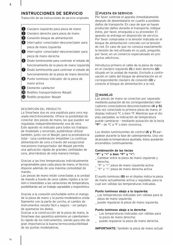
! Clavijero izquierdo para pieza de mano
@ Clavijero derecho para pieza de mano
# Conexión bloque de alimentación
$ Interruptor conectador-desconectador para
pieza de mano izquierda
% Interruptor conectador-desconectador para
pieza de mano derecha
^ Diodo luminiscente para controlar el estado de
funcionamiento de la pieza de mano izquierda
& Diodo luminiscente para controlar el estado de
funcionamiento de la pieza de mano derecha
* Punto luminoso indicador de la pieza de
mano activa
( Elemento calefactor
BL Rodillos transportadores Waxjet
BM Rodillo propulsor Waxjet
INSTRUCCIONES DE SERVICIOTraducción de las instrucciones de servicio originales
E
17
mente no seleccionada es calentada y por lo tantotambién la punta modeladora – ¡se enciende elcorrespondiente diodo luminiscente de control(6/7)! ¡En caso de que no quiera que una de laspiezas de mano siga calentándose, tendrá quedesconectarla completamente, pulsando el cor-respondiente interruptor conectador-desconecta-dor (4/5) o bien extrayendo la clavija de la piezade mano del clavijero!
Teclas “<” y “>”:_ Reducir la temperatura (<)_ Aumentar la temperatura (>)Una breve pulsación de las teclas provoca un cam-bio de temperatura de 1 °C. Mediante una pulsaciónmás larga, la temperatura aumentará (o bien dis-minuirá), primero paulatinamente y después a pasocreciente cada vez más rápido (aumento rápido).
Tecla “P”:_ Tecla de programa_ Cambio de la indicación de temperatura de °C a
°F tras conexión de la primera pieza de mano. _ Selección de las temperaturas programadas
P1 – P3 para cada pieza de mano (de forma continua).
El aparato ha sido programado en fábrica con lassiguientes temperaturas (para ambas piezas demano):P1 70 °C (158 °F)P2 100 °C (212 °F)P3 130 °C (266 °F)
Almacenamiento de los ajustes de temperatura:En cada una de las posiciones de programa P1 –P3 puede almacenarse también una temperaturaindividual:Seleccione para ello la posición de programa quequiera modificar (P1 – P3, mediante pulsación dela tecla “P”).Ajuste a continuación la temperatura deseada,pulsando la tecla “<” o bien “>”. Pulse ahora latecla “P” y manténgala pulsada durante unos 3segundos hasta parpadear la indicación de pro-gramas. La temperatura quedará almacenada,pudiéndose seleccionar de ahora en adelante enla correspondiente posición de programa mediantepulsación de la tecla “P”.
Cambio de las puntas modeladoras:Extraiga para ello el completo mango de corchohacia adelante en dirección de la punta modelado-ra. Las puntas modeladoras están unidas fijamentecon el mango de corcho, evitándose así automá-ticamente una torsión de la punta al modelar. Para montar un nuevo instrumento, coloque elmango sobre la pieza de mano hasta que ésteencaje audiblemente. En la parte posterior de la
unidad de mando podrán guardarse puntas mode-ladoras adicionales.
IMPORTANTE: Una vez extraído el mango decorcho, el elemento calefactor (9) quedará aldescubierto. ¡No tocar el elemento calefactor!¡Peligro de quemaduras!
Waxjet:El Waxjet es montado – como cualquier otro instru-mento modelador – sobre el mango de la pieza demano. Haga pasar el hilo de cera entre los rodillostransportadores (10) hasta producirse el contactocon la cuchara de fusión. Tan pronto como la ceracomience a fundirse, transporte el hilo de ceralenta y continuamente hacia delante, utilizandopara ello el rodillo propulsor (11) fijado lateralmente.El hilo de cera es transportado, girándose el rodillopropulsor en dirección de la punta modeladora.A fin de evitar burbujas de aire en la cera, nodebería cambiarse la dirección de transporte delhilo de cera de forma demasiado frecuente y rápida.
MANTENIMIENTOLa Smartwax duo ha sido concebida, al igual quela mayoría de los aparatos AmannGirrbach, exentade mantenimiento. Tan sólo debería cuidarse deque el aparato se mantenga siempre limpio. El mango con la punta modeladora debería podergirarse fácilmente sobre el mango de la pieza demano. Compruebe en caso contrario si el mangoy/o el elemento calefactor están sucios. ¡No limpielos instrumentos modeladores con objetos de filocortante, sino límpielos frotándolos con un pañoestando éstos todavía calientes!
E
18
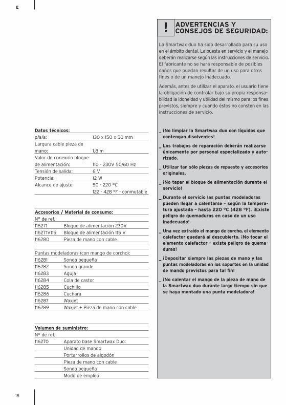
Datos técnicos:
p/a/a: 130 x 150 x 50 mm
Largura cable pieza de
mano: 1,8 m
Valor de conexión bloque
de alimentación: 110 - 230V 50/60 Hz
Tensión de salida: 6 V
Potencia: 12 W
Alcance de ajuste: 50 - 220 °C
122 - 428 °F - conmutable
Accesorios / Material de consumo:
N° de ref.
116271 Bloque de alimentación 230V
116271V115 Bloque de alimentación 115 V
116280 Pieza de mano con cable
Puntas modeladoras (con mango de corcho):
116281 Sonda pequeña
116282 Sonda grande
116283 Aguja
116284 Cola de castor
116285 Cuchillo
116286 Cuchara
116287 Waxjet
116289 Waxjet + Pieza de mano con cable
Volumen de suministro:
N° de ref.
116270 Aparato base Smartwax Duo:
Unidad de mando
Portarrollos de algodón
Pieza de mano con cable
Sonda pequeña
Modo de empleo
ADVERTENCIAS Y CONSEJOS DE SEGURIDAD:
La Smartwax duo ha sido desarrollada para su usoen el ámbito dental. La puesta en servicio y el manejodeberán realizarse según las instrucciones de servicio.El fabricante no se hará responsable de posiblesdaños que puedan resultar de un uso para otrosfines o de un manejo inadecuado.
Además, antes de utilizar el aparato, el usuario tienela obligación de controlar bajo su propia responsa-bilidad la idoneidad y utilidad del mismo para los finesprevistos, siempre y cuando éstos no consten en lasinstrucciones de servicio.
_ ¡No limpiar la Smartwax duo con líquidos que contengan disolventes!
_ Los trabajos de reparación deberán realizarse únicamente por personal especializado y auto-rizado.
_ Utilizar tan sólo piezas de repuesto y accesoriosoriginales.
_ ¡No tapar el bloque de alimentación durante el servicio!
_ Durante el servicio las puntas modeladoras pueden llegar a calentarse – según la tempera-tura ajustada – hasta 220 °C (428 °F). ¡Existepeligro de quemaduras en caso de un uso inadecuado!
_ Una vez extraído el mango de corcho, el elementocalefactor quedará al descubierto. ¡No tocar el elemento calefactor – existe peligro de quema-duras!
_ ¡Depositar siempre las piezas de mano y las puntas modeladoras en los soportes en la unidadde mando previstos para tal fin!
_ ¡No calentar el mango de la pieza de mano de la Smartwax duo durante largo tiempo sin que se haya montado una punta modeladora!
!

19
20

21
ww
w.h
ellb
lau
.co
m30
34
0-F
B20
11-0
2-0
7
Made in the European Union
Distribution | Vertrieb D/A
Amann Girrbach GmbHDürrenweg 4075177 Pforzheim | GermanyFon +49 7231 957-100Fax +49 7231 957-159
[email protected]@amanngirrbach.com
www.amanngirrbach.com
Manufacturer | HerstellerDistribution | Vertrieb
Amann Girrbach AGHerrschaftswiesen 16842 Koblach | AustriaFon +43 5523 62333-0Fax +43 5523 55990
ISO 9001QU
ALI
TÄTSMANAGEMEN
T