Embed Size (px)
Citation preview
DAQ Getting Started GuideThis document contains English, French, German, Japanese, and Korean language instructions.
Ce document contient des instructions en anglais, français, allemand, japonais et coréen.
Dieses Dokument ist mehrsprachig und enthält einen englischen, französischen, deutschen, japanischen und koreanischen Teil.
This guide describes how to install and configure the NI-DAQmx driver software for Windows and your NI data acquisition (DAQ) device, and confirm the device is operating properly. For Linux installation instructions, refer to the NI-DAQmx for Linux Readme, available at ni.com/downloads. For instructions on configuring Traditional NI-DAQ (Legacy), refer to the Traditional NI-DAQ (Legacy) Readme, accessible from Start»All Programs»National Instruments»NI-DAQ after you have installed the software.
NI-DAQ SoftwareNational Instruments measurement devices, such as the M Series multifunction I/O (MIO) DAQ devices, are packaged with NI-DAQ driver software, an extensive library of VIs, ANSI C, and .NET functions you can call from your application software, such as NI LabVIEW, NI LabWindows™/CVI™, Microsoft Visual Studio .NET, or NI LabVIEW SignalExpress to program your NI device. Driver software has an application programming interface (API), which is a library of VIs, functions, classes, attributes, and properties for creating applications for your device.
With NI-DAQ 7.x and later, there are two NI-DAQ drivers, each with its own APIs and configuration. NI-DAQmx is the latest NI-DAQ driver with advantages over Traditional NI-DAQ (Legacy).
• DAQ Assistant—a graphical way to configure virtual channels and measurement tasks for your device, and to generate NI-DAQmx code based on your virtual channels and tasks, for use in LabVIEW, LabWindows/CVI, Measurement Studio, VI Logger, LabVIEW SignalExpress, and Measurement & Automation Explorer (MAX)
• Increased performance, including faster single-point analog I/O and multithreading
• NI-DAQmx simulation for most supported devices for testing and modifying applications without plugging in hardware; refer to the NI-DAQ Readme for NI-DAQmx-supported devices that do not have NI-DAQmx simulated device capability
• Simpler, more intuitive APIs for creating DAQ applications using fewer functions and VIs than earlier versions of NI-DAQ
Traditional NI-DAQ (Legacy) is an older driver with outdated APIs for developing data acquisition, instrumentation, and control applications for older National Instruments DAQ devices. You should use Traditional NI-DAQ (Legacy) only in certain circumstances. Refer to the NI-DAQ Readme for more information about when to use Traditional NI-DAQ (Legacy), including a complete list of supported devices, operating systems, and application software and language versions. If you must use Traditional NI-DAQ (Legacy), it is available at ni.com/downloads.
DAQ Getting Started Guide 2 ni.com
Step 1. Install Application SoftwareInstall your NI application software. NI-DAQmx is supported in LabVIEW, LabWindows/CVI, and Measurement Studio versions 7.x or later, LabVIEW SignalExpress 2.x or later, or the LabVIEW Real-Time Module 7.1 or later. If you have an existing application written with an earlier version of your application software or NI-DAQ, make a backup copy of the application. You then can upgrade your software and modify the application.
Step 2. Install NI-DAQInstall your driver software before installing new hardware devices so Windows can detect your device. Do not install NI-DAQ if your existing applications include unsupported components, which are listed in the NI-DAQ Readme.
Caution NI-DAQ 7.x or later cannot exist on the same system with versions of NI-DAQ previous to version 7.0.
1. Insert CD 1. The NI-DAQ installer should open automatically. If not, select Start»Run. Enter x:\autorun.exe, where x is the letter of the CD drive. For troubleshooting instructions, refer to the Hardware Installation/Configuration Troubleshooter at ni.com/support/install.
2. Install the software.
• Install Software copies the software and/or documentation files onto your hard drive. NI-DAQ software documentation is installed when you install the driver software.
• View Readme File opens the readme file.
• Browse CD opens the device documentation so that you can find, view, and print documents without installing them.
The NI-DAQ installer detects the NI software installed on the system and automatically selects the latest versions of the driver, application software, and language support files from the CDs. Verify that the installer detected and selected the correct support files and version number. If you install NI application software after installing NI-DAQ, you must run the NI-DAQ installer again to install the correct application software support.
3. Follow the prompts. Windows Vista users may see access and security messages during installation. Accept the prompts to complete the installation.
4. As the NI-DAQ installer completes, several dialog boxes are displayed. Click Next to complete the installation.
5. The last dialog box opens with the following options.
• Restart Later to install more NI software or documentation.
– Install online documentation for supported devices and accessories, including PDF and help files describing device terminals, specifications, features, and operation. Insert the Device Documentation CD 2 and open the installer screen. Select Install Device Documentation.
– If you are using a MXI-3 link from a PC to control a PXI chassis, exit and install the MXI-3 software, available at ni.com/downloads, before using the DAQ device.
• Shut Down or Restart if you are ready to install your device.
• Restart if you are using a system running the LabVIEW Real-Time Module. Download NI-DAQ to the target using MAX. Refer to the Measurement & Automation Explorer Remote Systems Help by selecting Help»Help Topics»Remote Systems in MAX.
© National Instruments Corporation 3 DAQ Getting Started Guide
Step 3. Unpack the Devices, Accessories, and CablesRemove the device from the package and inspect the device for loose components or any sign of damage. Notify NI if the device appears damaged in any way. Do not install a damaged device.
For safety and compliance information, refer to the device documentation, available at ni.com/manuals or accessible from Start»All Programs»National Instruments»NI-DAQ»Browse Device Documentation after you install it.
The following symbols may be on your device.
This icon denotes a caution, which advises you of precautions to take to avoid injury, data loss, or a system crash. When this symbol is marked on the device, refer to the Read Me First: Safety and Radio-Frequency Interference document, shipped with the device, for precautions to take.
When this symbol is marked on a product, it denotes a warning advising you to take precautions to avoid electrical shock.
When this symbol is marked on a product, it denotes a component that may be hot. Touching this component may result in bodily injury.
Step 4. Install the Devices, Accessories, and CablesIf you have more than one DAQ device to install, install them all now using the following procedure for your device type. If your system includes SCXI modules to connect to DAQ devices, first install the DAQ components.
Caution Follow proper ESD precautions to ensure you are grounded before installing hardware. Refer to your device specifications document for important safety and compliance information.
You can test NI-DAQmx applications without installing hardware by using an NI-DAQmx simulated device. Refer to the Measurement & Automation Explorer Help for NI-DAQmx by selecting Help»Help Topics»NI-DAQmx in MAX for instructions on creating NI-DAQmx simulated devices and importing NI-DAQmx simulated device configurations to physical devices.
CompactDAQComplete the following steps to install a C Series I/O module:
1. Power off the CompactDAQ chassis.
2. If you are not using any mounting accessories, attach the provided rubber standoffs to the back of the CompactDAQ chassis. Attach a ring lug to a 14 AWG (1.6 mm) wire. Connect the ring lug to the ground terminal on the side of the chassis using the ground screw. Attach the other end of the wire to the system safety ground.
Additionally, attach a wire with a ring lug to all other C Series I/O module cable shields. You must connect this wire to the ground terminal of the chassis using the ground screw.
Caution If hazardous voltages are present, special safety guidelines apply. Refer to the C Series module user guide before continuing. Hazardous voltage is a voltage greater than 42.4 V or 60 VDC to earth ground.
3. Squeeze both C Series I/O module latches, insert the I/O module into an empty module slot, and press until both latches lock the module in place. Refer to the C Series I/O module user guide for more information, such as signal connections, safety precautions, and module ratings.
DAQ Getting Started Guide 4 ni.com
.
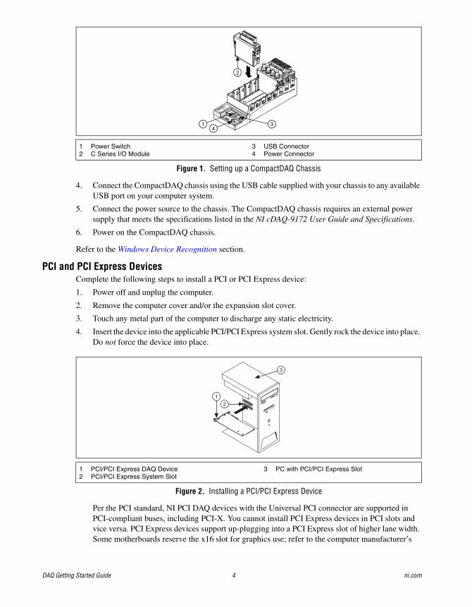
Figure 1. Setting up a CompactDAQ Chassis
4. Connect the CompactDAQ chassis using the USB cable supplied with your chassis to any available USB port on your computer system.
5. Connect the power source to the chassis. The CompactDAQ chassis requires an external power supply that meets the specifications listed in the NI cDAQ-9172 User Guide and Specifications.
6. Power on the CompactDAQ chassis.
Refer to the Windows Device Recognition section.
PCI and PCI Express DevicesComplete the following steps to install a PCI or PCI Express device:
1. Power off and unplug the computer.
2. Remove the computer cover and/or the expansion slot cover.
3. Touch any metal part of the computer to discharge any static electricity.
4. Insert the device into the applicable PCI/PCI Express system slot. Gently rock the device into place. Do not force the device into place.
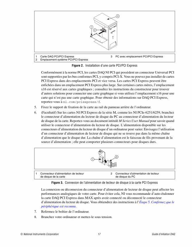
Figure 2. Installing a PCI/PCI Express Device
Per the PCI standard, NI PCI DAQ devices with the Universal PCI connector are supported in PCI-compliant buses, including PCI-X. You cannot install PCI Express devices in PCI slots and vice versa. PCI Express devices support up-plugging into a PCI Express slot of higher lane width. Some motherboards reserve the x16 slot for graphics use; refer to the computer manufacturer’s
1 Power Switch 2 C Series I/O Module
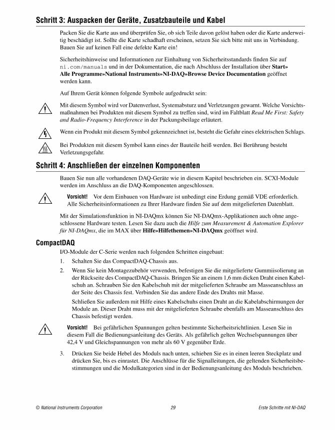
3 USB Connector4 Power Connector
1 PCI/PCI Express DAQ Device2 PCI/PCI Express System Slot
3 PC with PCI/PCI Express Slot
NI cDAQ-9051
Ready
Active
11-30 VDC
2 A Max
OFF
ON
431
2
3
12
© National Instruments Corporation 5 DAQ Getting Started Guide
instructions for alternative graphics solutions if using the x16 slot for nongraphics devices. For guidelines on PCI Express, refer to ni.com/pciexpress.
5. Secure the device mounting bracket to the computer back panel rail.
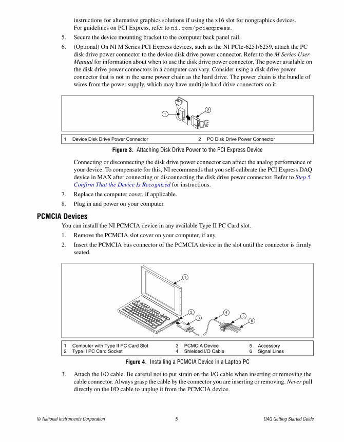
6. (Optional) On NI M Series PCI Express devices, such as the NI PCIe-6251/6259, attach the PC disk drive power connector to the device disk drive power connector. Refer to the M Series User Manual for information about when to use the disk drive power connector. The power available on the disk drive power connectors in a computer can vary. Consider using a disk drive power connector that is not in the same power chain as the hard drive. The power chain is the bundle of wires from the power supply, which may have multiple hard drive connectors on it.
Figure 3. Attaching Disk Drive Power to the PCI Express Device
Connecting or disconnecting the disk drive power connector can affect the analog performance of your device. To compensate for this, NI recommends that you self-calibrate the PCI Express DAQ device in MAX after connecting or disconnecting the disk drive power connector. Refer to Step 5. Confirm That the Device Is Recognized for instructions.
7. Replace the computer cover, if applicable.
8. Plug in and power on your computer.
PCMCIA DevicesYou can install the NI PCMCIA device in any available Type II PC Card slot.
1. Remove the PCMCIA slot cover on your computer, if any.
2. Insert the PCMCIA bus connector of the PCMCIA device in the slot until the connector is firmly seated.
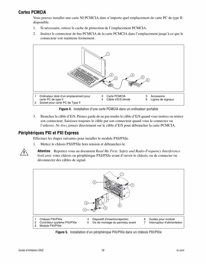
Figure 4. Installing a PCMCIA Device in a Laptop PC
3. Attach the I/O cable. Be careful not to put strain on the I/O cable when inserting or removing the cable connector. Always grasp the cable by the connector you are inserting or removing. Never pull directly on the I/O cable to unplug it from the PCMCIA device.
1 Device Disk Drive Power Connector 2 PC Disk Drive Power Connector
1 Computer with Type II PC Card Slot2 Type II PC Card Socket
3 PCMCIA Device4 Shielded I/O Cable
5 Accessory6 Signal Lines
12
®
®
DAQCard
1
2
34
56
DAQ Getting Started Guide 6 ni.com
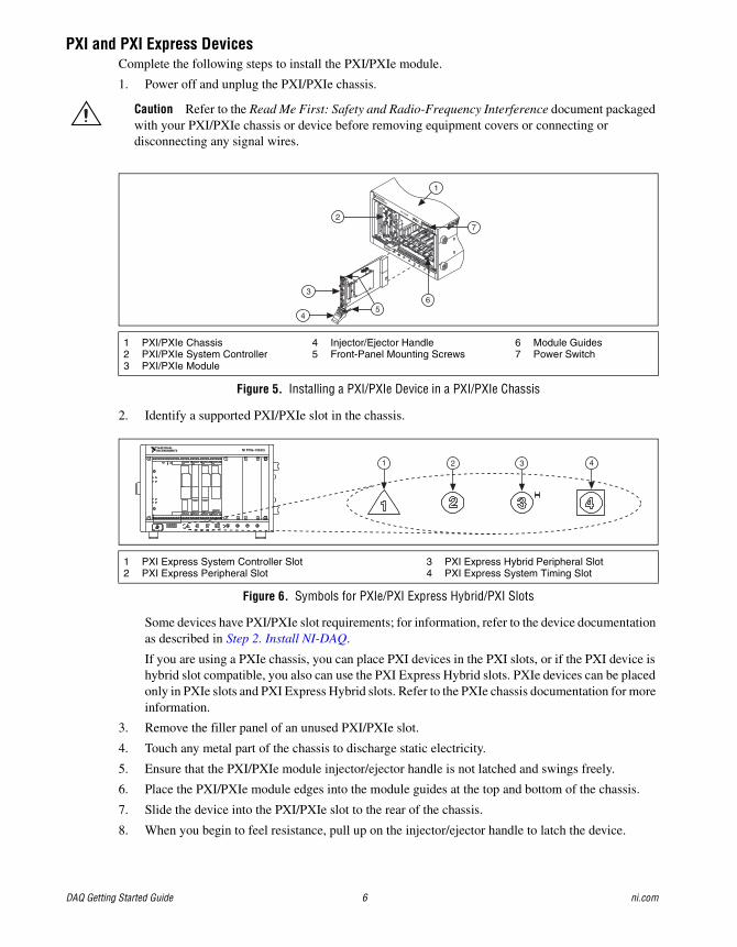
PXI and PXI Express DevicesComplete the following steps to install the PXI/PXIe module.
1. Power off and unplug the PXI/PXIe chassis.
Caution Refer to the Read Me First: Safety and Radio-Frequency Interference document packaged with your PXI/PXIe chassis or device before removing equipment covers or connecting or disconnecting any signal wires.
Figure 5. Installing a PXI/PXIe Device in a PXI/PXIe Chassis
2. Identify a supported PXI/PXIe slot in the chassis.
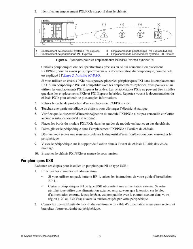
Figure 6. Symbols for PXIe/PXI Express Hybrid/PXI Slots
Some devices have PXI/PXIe slot requirements; for information, refer to the device documentation as described in Step 2. Install NI-DAQ.
If you are using a PXIe chassis, you can place PXI devices in the PXI slots, or if the PXI device is hybrid slot compatible, you also can use the PXI Express Hybrid slots. PXIe devices can be placed only in PXIe slots and PXI Express Hybrid slots. Refer to the PXIe chassis documentation for more information.
3. Remove the filler panel of an unused PXI/PXIe slot.
4. Touch any metal part of the chassis to discharge static electricity.
5. Ensure that the PXI/PXIe module injector/ejector handle is not latched and swings freely.
6. Place the PXI/PXIe module edges into the module guides at the top and bottom of the chassis.
7. Slide the device into the PXI/PXIe slot to the rear of the chassis.
8. When you begin to feel resistance, pull up on the injector/ejector handle to latch the device.
1 PXI/PXIe Chassis2 PXI/PXIe System Controller3 PXI/PXIe Module
4 Injector/Ejector Handle5 Front-Panel Mounting Screws
6 Module Guides7 Power Switch
1 PXI Express System Controller Slot2 PXI Express Peripheral Slot
3 PXI Express Hybrid Peripheral Slot4 PXI Express System Timing Slot
3
2
4
PXI-1000B
7
56
1
NI PXIe-1062Q
1 2 3 4
© National Instruments Corporation 7 DAQ Getting Started Guide
9. Secure the device front panel to the chassis front panel mounting rail using the front-panel mounting screws.
10. Plug in and power on your PXI/PXIe chassis.
USB DevicesComplete these steps to install an NI device for USB:
1. Make power connections.
• If you are using the BP-1 battery pack, follow the installation instructions in your BP-1 installation guide.
• Some NI devices for USB require external power. If your device has an external power supply, verify that the voltage on the external power supply, if any, matches the voltage in your area (120 or 230 VAC) and the voltage required by your device.
2. Connect one end of the power supply or power cord to an electrical outlet and the other end to your device.
3. Connect the cable from the computer USB port or from any other hub to any available USB port on the device.
4. If you have a USB device with a power switch, power on the device. The computer should immediately detect your device.
When the computer recognizes a USB device, the LED on the device blinks or lights up. Refer to the device documentation for LED pattern descriptions.
Windows Device RecognitionWindows recognizes any newly installed device the first time the computer reboots after hardware is installed. On some Windows systems, the Found New Hardware wizard opens with a dialog box for every NI device installed. Install the software automatically (Recommended) is selected by default. Click Next or Yes to install the software for each device.
After Windows recognizes newly installed NI USB devices, including CompactDAQ devices, a dialog box prompts you to select from the following options, which may vary depending on the devices and software installed on your system:
• Begin a Measurement with LabVIEW launches LabVIEW.
• Begin a Measurement with This Device Using NI LabVIEW SignalExpress opens a DAQ step that uses the channels from your device in LabVIEW SignalExpress. If you have installed a CompactDAQ chassis, a dialog box prompts you to select the modules you want to use. If you have accessories, SCXI, or sensors to attach and configure, refer to the following Accessories section and Step 5. Confirm That the Device Is Recognized through Step 9. Run Test Panels. Otherwise, you do not need to configure any settings in MAX. Refer to Step 11. Use NI-DAQmx with Your Application Software to learn more about taking DAQ measurements in LabVIEW SignalExpress.
• Configure and Test This Device opens MAX to your device so that you can configure settings.
• Run Test Panels launches MAX test panels for your device.
• Take No Action leaves your device in the system but does not launch an application.
AccessoriesInstall accessories and/or terminal blocks according to the instructions in their installation guides. For SCXI and SCC signal conditioning systems, continue with the instructions in this guide through Step 7. Install Signal Conditioning or Switch Devices.
DAQ Getting Started Guide 8 ni.com
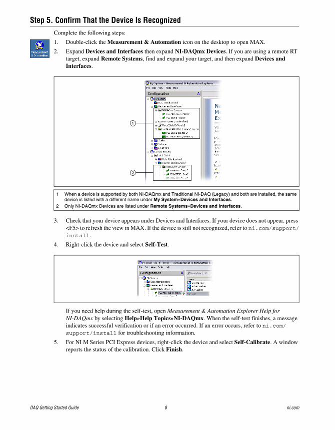
Step 5. Confirm That the Device Is RecognizedComplete the following steps:
1. Double-click the Measurement & Automation icon on the desktop to open MAX.
2. Expand Devices and Interfaces then expand NI-DAQmx Devices. If you are using a remote RT target, expand Remote Systems, find and expand your target, and then expand Devices and Interfaces.
3. Check that your device appears under Devices and Interfaces. If your device does not appear, press <F5> to refresh the view in MAX. If the device is still not recognized, refer to ni.com/support/install.
4. Right-click the device and select Self-Test.
If you need help during the self-test, open Measurement & Automation Explorer Help for NI-DAQmx by selecting Help»Help Topics»NI-DAQmx. When the self-test finishes, a message indicates successful verification or if an error occurred. If an error occurs, refer to ni.com/support/install for troubleshooting information.
5. For NI M Series PCI Express devices, right-click the device and select Self-Calibrate. A window reports the status of the calibration. Click Finish.
1 When a device is supported by both NI-DAQmx and Traditional NI-DAQ (Legacy) and both are installed, the same device is listed with a different name under My System»Devices and Interfaces.
2 Only NI-DAQmx Devices are listed under Remote Systems»Devices and Interfaces.
1
2
© National Instruments Corporation 9 DAQ Getting Started Guide
Step 6. Configure the Device SettingsConfigure each device you install:
1. Right-click the device name and select Properties. Be sure to click the device name under the folder for the system (My System or Remote Systems) and NI-DAQ API in which you want to control the device.
2. Configure the device properties.
• If you are using an accessory, add the accessory information.
• For IEEE 1451.4 transducer electronic data sheet (TEDS) sensors and accessories, configure the device and add the accessory as previously described. Click Scan for TEDS. To configure TEDS sensors cabled directly to a device, in MAX, right-click the device under Devices and Interfaces and select Configure TEDS.
3. Click OK to accept the changes.
Step 7. Install Signal Conditioning or Switch DevicesIf your system includes SCXI signal conditioning modules, Signal Conditioning Components (SCC) such as SC carriers and SCC modules, terminal blocks, or switch modules, refer to the getting started guide for the product to install and configure the signal conditioning or switch hardware.
Step 8. Attach Sensors and Signal LinesAttach sensors and signal lines to the terminal block or accessory terminals for each installed device.
Pin assignments (pinouts) are in the NI-DAQmx Device Terminals Help in the Measurement & Automation Explorer Help for NI-DAQmx, accessible from the MAX Help menu, and in the device documents on the Device Document Browser, accessible from Start»All Programs»National Instruments»NI-DAQ»Browse Device Documentation after you install it. You can view and print a connection diagram for NI-DAQmx tasks and virtual channels in your system through the DAQ Assistant. Refer to Configure a Task Using the DAQ Assistant from MAX to open the DAQ Assistant. Select the task or virtual channel and click the Connection Diagram tab. Select each virtual channel in the task to view the terminal names and numbers for connections from sensor to connector block.
For information about sensors, refer to ni.com/sensors or Sensors in the NI-DAQmx Help, which you can access from Start»All Programs»National Instruments»NI-DAQ»NI-DAQmx Help. For information about IEEE 1451.4 TEDS smart sensors, refer to ni.com/teds.
If you are using LabVIEW SignalExpress, refer to Step 11. Use NI-DAQmx with Your Application Software.
Step 9. Run Test PanelsMany devices have a test panel for testing specific device functionality, such as the ability to acquire and generate signals.
1. In MAX, expand Devices and Interfaces»NI-DAQmx Devices. If you are using a remote RT target, expand Remote Systems, find and expand your target, then expand Devices and Interfaces.
2. Right-click the device to test.
DAQ Getting Started Guide 10 ni.com
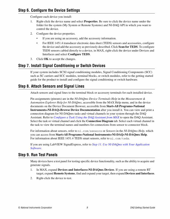
3. Select Test Panels to open a test panel for the selected device, shown in the following example.
4. Click the tabs to test different functions of the device or click Help for instructions about operating the test panels. The test panel displays a message indicating whether an error occurred. If so, refer to the NI-DAQmx Help or ni.com/support for troubleshooting information.
5. Click Close to exit the test panel.
Step 10. Take an NI-DAQmx Measurement
NI-DAQmx Channels and Tasks A physical channel is a terminal or pin at which you can measure or generate an analog or digital signal. A virtual channel maps a name to a physical channel and its settings, such as input terminal connections, the type of measurement or generation, and scaling information. In NI-DAQmx, virtual channels are integral to every measurement.
A task is one or more virtual channels with timing, triggering, and other properties. Conceptually, a task represents a measurement or generation to perform. You can set up and save configuration information in a task and use the task in an application. Refer to the NI-DAQmx Help for complete information about channels and tasks.
With NI-DAQmx, you use the DAQ Assistant to configure virtual channels and tasks in MAX or in your application software.
Configure a Task Using the DAQ Assistant from MAXComplete the following steps to create a task using the DAQ Assistant in MAX:
1. In MAX, right-click Data Neighborhood and select Create New to open the DAQ Assistant.
2. In the Create New window, select NI-DAQmx Task and click Next.
3. Select Acquire Signals or Generate Signals.
4. Select the I/O type, such as analog input, and the measurement type, such as voltage.
© National Instruments Corporation 11 DAQ Getting Started Guide
5. Select the physical channel(s) to use and click Next.
6. Name the task and click Finish.
7. Configure individual channel settings. Each physical channel you assign to a task receives a virtual channel name. To modify the input range or other settings, select the channel. Click Show Details for physical channel information. Configure the timing and triggering for your task. Click Test.
Step 11. Use NI-DAQmx with Your Application SoftwareYou can use the DAQ Assistant with version 7.x or later of LabVIEW, LabWindows/CVI, or Measurement Studio, or with version 2.x or later of LabVIEW SignalExpress.
The NI-DAQmx CDs include LabVIEW SignalExpress LE, an easy-to-use configuration-based tool specifically designed for data logging applications. The application is at Start»All Programs»National Instruments»LabVIEW SignalExpress. The LabVIEW SignalExpress Help is within LabVIEW SignalExpress at Help»Help Topics»LabVIEW SignalExpress.
To get started in your application software, refer to the tutorials:
• The LabVIEW DAQ Assistant tutorial is located within LabVIEW at Help»Getting Started»Getting Started with DAQ»Taking an NI-DAQmx Measurement in LabVIEW.
• The LabWindows/CVI DAQ Assistant tutorial is located within LabWindows/CVI at Help»Help Topics»Taking an NI-DAQmx Measurement in LabWindows/CVI.
• The Measurement Studio DAQ Assistant tutorial is located at Measurement Studio»NI Measurement Studio Help»Getting Started with the Measurement Studio Class Libraries»Measurement Studio Walkthroughs»Walkthrough: Creating a Measurement Studio NI-DAQmx Application.
• The LabVIEW SignalExpress DAQ Assistant tutorial is located within LabVIEW SignalExpress at Help»Getting Started with»Taking an NI-DAQmx Measurement in LabVIEW SignalExpress.
ExamplesYou can use examples to develop a new application or add example code to an existing application.
For additional examples, refer to ni.com/zone. To run examples without hardware installed, you can use an NI-DAQmx simulated device. In MAX, refer to the Measurement & Automation Explorer Help for NI-DAQmx by selecting Help»Help Topics»NI-DAQmx for information about creating NI-DAQmx simulated devices.
Software Application Example Location
LabVIEW or LabWindows/CVI Help»Find Examples
LabVIEW SignalExpress Program Files\National Instruments\SignalExpress\Examples
ANSI C NI-DAQ\Examples\DAQmx ANSI C
Measurement Studio-supported languages MFC 7.0 C++ NI-DAQ\Examples\MStudioVC2003
Visual Basic .NET and C# examples for Visual Studio 2003* NI-DAQ\Examples\DotNET1.1
MFC 8.0 C++ NI-DAQ\Examples\MStudioVC2005
Visual Basic .NET and C# examples for Visual Studio 2005* NI-DAQ\Examples\DotNET2.0
* Do not require Measurement Studio
National Instruments, NI, ni.com, and LabVIEW are trademarks of National Instruments Corporation. Refer to the Terms of Use section on ni.com/legal for more information about National Instruments trademarks. Other product and company names mentioned herein are trademarks or trade names of their respective companies. For patents covering National Instruments products, refer to the appropriate location: Help»Patents in your software, the patents.txt file on your CD, or ni.com/patents.
© 2003–2007 National Instruments Corporation. All rights reserved. 373235M Jun07
More InformationAfter you install the device documentation, the browser and device documents are accessible from Start»All Programs»National Instruments»NI-DAQ»Browse Device Documentation. The NI-DAQ software documents, such as the NI-DAQmx Help and DAQ Getting Started Guide, are accessible from Start»All Programs»National Instruments»NI-DAQ»NI-DAQmx document title.
You also can access online device documentation by right-clicking your device in MAX and selecting Help»Online Device Documentation. A browser window opens to ni.com/manuals with the results of a search for relevant device documents. The ni.com/manuals Web site also contains documents for new devices that are released between NI-DAQmx releases and newer revisions of device documentation that are not yet available on the NI-DAQ device document browser.
TroubleshootingUse the following resources if you have problems installing your DAQ hardware and/or software:
• For troubleshooting instructions, refer to the Hardware Installation/Configuration Troubleshooter at ni.com/support/install.
• Refer to ni.com/kb for documents about troubleshooting common installation and programming problems and for answering frequently asked questions about NI products.
• If you think you have damaged your device and need to return your National Instruments hardware for repair or device calibration, refer to ni.com/info and enter the info code rdsenn to learn how to begin the Return Merchandise Authorization (RMA) process.
Worldwide Technical SupportFor additional support, refer to ni.com/support or ni.com/zone. For further support information for signal conditioning products, refer to the Signal Conditioning Technical Support Information document packaged with your device.
National Instruments corporate headquarters is located at 11500 North Mopac Expressway, Austin, Texas, 78759-3504. National Instruments also has offices located around the world to help address your support needs.
Guide d’initiation DAQCe guide décrit les étapes à suivre pour installer et configurer le driver NI-DAQmx pour Windows, ainsi que votre périphérique d’acquisition de données (DAQ) NI et confirmer que ce périphérique fonctionne correctement. Pour obtenir des instructions relatives à l’installation sous Linux, reportez-vous au fichier Readme intitulé NI-DAQmx for Linux Readme, disponible sur ni.com/downloads. Vous trouverez des instructions de configuration de NI-DAQ traditionnel (ancien driver) en cliquant sur le lien Fichier Readme de NI-DAQ traditionnel (ancien driver) dans le fichier Readme NI-DAQ, accessible sous Démarrer»Tous les programmes»National Instruments»NI-DAQ après avoir installé le logiciel.
Logiciel NI-DAQLes périphériques de mesure National Instruments, comme les périphériques d’E/S multifonctions (MIO) de la série M, sont fournis avec le logiciel de drivers NI-DAQ, une bibliothèque contenant de nombreux VIs et fonctions .NET et C ANSI que vous pouvez appeler à partir de votre logiciel d’application, comme NI LabVIEW, NI LabWindows™/CVI™, Microsoft Visual Studio .NET ou NI LabVIEW SignalExpress, pour programmer votre périphérique NI. Le driver est constitué d’une API (Application Programming Interface) qui est une bibliothèque de VIs, fonctions, classes, attributs et propriétés pour créer des applications pour votre périphérique.
NI-DAQ 7.x et versions ultérieures comprennent deux drivers NI-DAQ ayant leurs propres API et configuration. NI-DAQmx est le tout dernier driver NI-DAQ ; il possède certains avantages par rapport à NI-DAQ traditionnel (ancien driver).
• Assistant DAQ, méthode graphique permettant de configurer des voies virtuelles et des tâches de mesure pour votre périphérique, et de générer du code NI-DAQmx basé sur vos voies virtuelles et vos tâches, en vue de l’utiliser avec LabVIEW, LabWindows/CVI, Measurement Studio, VI Logger, LabVIEW SignalExpress et Measurement & Automation Explorer (MAX).
• Des performances accrues, notamment un multithreading et des E/S analogiques point par point plus rapides.
• La simulation par NI-DAQmx de la plupart des périphériques supportés, afin de tester et de modifier des applications sans connecter de matériel ; reportez-vous au fichier Readme NI-DAQ pour obtenir la liste des périphériques supportés par NI-DAQmx qui ne peuvent pas être simulés par NI-DAQmx.
• Des API plus simples et plus intuitives pour créer des applications DAQ en utilisant moins de fonctions et de VIs que les versions antérieures de NI-DAQ.
NI-DAQ traditionnel (ancien driver) est un ancien driver dont les API (obsolètes) permettent de développer des applications d’acquisition de données, d’instrumentation et de contrôle conçues pour les anciens périphériques DAQ National Instruments. Vous devriez utiliser NI-DAQ traditionnel (ancien driver) uniquement dans certaines circonstances. Reportez-vous au fichier Readme NI-DAQ pour savoir dans quels cas l’utilisation de NI-DAQ traditionnel (ancien driver) se justifie et pour obtenir des informations complémentaires, notamment la liste des périphériques, systèmes d’exploitation et versions de logiciel d’application et de langages supportés. Si vous devez utiliser NI-DAQ traditionnel (ancien driver), il est disponible à ni.com/downloads.
Guide d’initiation DAQ 14 ni.com
Étape 1. Installez le logiciel d'applicationInstallez votre logiciel d’application NI. NI-DAQmx est supporté par LabVIEW, LabWindows/CVI, Measurement Studio versions 7.x ou version ultérieure, LabVIEW SignalExpress 2.x ou version ultérieure, et le module LabVIEW Real-Time 7.1 ou version ultérieure. Si vous avez une application qui a été développée avec une version antérieure de votre logiciel d’application ou de NI-DAQ, faites-en une copie de sauvegarde. Vous pouvez ensuite mettre à jour votre logiciel et modifier l’application.
Étape 2. Installez NI-DAQInstallez le logiciel de drivers avant d’installer de nouveaux périphériques matériels, de sorte que Windows puisse détecter vos périphériques. N’installez pas NI-DAQ si votre application existante comprend des éléments non supportés, répertoriés dans le fichier NI-DAQ Readme.
Attention NI-DAQ 7.x et versions ultérieures ne peuvent pas fonctionner sur un ordinateur sur lequel des versions de NI-DAQ antérieures à 7.0 sont installées.
1. Insérez le CD 1. L’installeur NI-DAQ doit se lancer automatiquement. Si ce n’est pas le cas, sélectionnez Démarrer»Exécuter. Entrez x:\autorun.exe, x correspondant à la lettre du lecteur de CD. Pour consulter des instructions de dépannage, reportez-vous à la rubrique Hardware Installation / Configuration Troubleshooter sur ni.com/support/install.
2. Installez le logiciel.
• Installer le logiciel copie les fichiers du logiciel et/ou de la documentation sur votre disque dur. La documentation du logiciel NI-DAQ est installée lorsque vous installez le logiciel de drivers.
• Afficher le fichier ReadMe ouvre le fichier readme.
• Parcourir le CD ouvre la documentation sur les périphériques pour vous permettre de rechercher, d’afficher et d’imprimer des documents sans les installer.
L’installeur NI-DAQ détecte tous les logiciels NI installés sur le système et choisit automatiquement sur le CD les fichiers support les plus récents des drivers, des logiciels d’application et des langages qu’il a détectés. Vérifiez que l’installeur a détecté et sélectionné les fichiers support corrects et le bon numéro de version. Si vous installez un logiciel d’application NI après avoir installé NI-DAQ, vous devez relancer l’installeur NI-DAQ pour installer le fichier support qui correspond à ce logiciel d’application.
3. Suivez les instructions. Si vous utilisez Windows Vista, il se peut que des messages d’accès et de sécurité apparaissent lors de l’installation. Acceptez les invites pour terminer l’installation.
4. À la fin de l’installeur NI-DAQ, plusieurs boîtes de dialogue apparaissent. Cliquez sur Suivant pour terminer l’installation.
5. La dernière boîte de dialogue propose les options suivantes.
• Cliquez sur Redémarrer ultérieurement pour installer un autre logiciel NI ou de la documentation supplémentaire.
– Installez la documentation en ligne pour les périphériques et les accessoires supportés, notamment des fichiers PDF et des fichiers d’aide décrivant les terminaux, les spécifications, les fonctionnalités et le mode d’opération du périphérique. Insérez le CD 2, Device Documentation, qui contient la documentation puis ouvrez l’écran de l’installeur. Sélectionnez Install Device Documentation.
– Si vous utilisez un lien MXI-3 à partir d’un PC pour contrôler un châssis PXI, vous devez quitter le programme et installer le logiciel MXI-3, disponible sur ni.com/downloads, avant d’utiliser le périphérique DAQ.
© National Instruments Corporation 15 Guide d’initiation DAQ
• Cliquez sur Arrêter ou Redémarrer si vous êtes prêt à installer votre périphérique.
• Cliquez sur Redémarrer si vous utilisez un système qui exécute le module LabVIEW Real-Time. Téléchargez NI-DAQ sur la cible en utilisant MAX. Reportez-vous à l’Aide de Measurement & Automation Explorer pour les systèmes déportés en sélectionnant Aide»Rubriques de l’aide»Systèmes déportés dans MAX.
Étape 3. Déballez les périphériques, les accessoires et les câblesRetirez le périphérique de son emballage et assurez-vous qu’il n’est pas endommagé et que ses composants sont bien en place. Contactez NI si le périphérique semble endommagé. N’installez pas un périphérique endommagé.
Vous trouverez des informations sur la sécurité et la conformité dans la documentation des périphériques, disponible sur ni.com/manuals ou à partir de Démarrer»Tous les programmes»National Instruments»NI-DAQ»Browse Device Documentation après l’avoir installée.
Les symboles suivants peuvent figurer sur votre périphérique.
Cette icône signale un avertissement qui vous indique les précautions à prendre pour éviter des préjudices corporels, des pertes de données ou un crash du système. Si ce symbole est présent sur le périphérique, reportez-vous au document Read Me First: Safety and Radio-Frequency Interference, livré avec le périphérique, pour vous renseigner sur les précautions à prendre.
La présence de ce symbole sur un produit indique une mise en garde vous conseillant de prendre des précautions pour éviter les chocs électriques.
La présence de ce symbole sur un produit indique qu’un composant risque d’être brûlant. Toucher ce composant peut provoquer des préjudices corporels.
Étape 4. Installez les périphériques, les accessoires et les câblesSi vous devez installer plusieurs périphériques DAQ, installez-les maintenant en utilisant la procédure appropriée à chaque périphérique. Si votre système comporte des modules SCXI à connecter à des périphériques DAQ, installez d’abord les composants DAQ.
Attention Prenez les précautions nécessaires pour éviter les décharges électrostatiques avant d’installer le matériel. Consultez le document des spécifications se rapportant à votre périphérique pour lire des informations importantes concernant la sécurité et la compatibilité.
Vous pouvez tester des applications NI-DAQmx sans installer de matériel en utilisant un périphérique simulé NI-DAQmx. Reportez-vous à l’Aide Measurement & Automation Explorer pour NI-DAQmx en sélectionnant Aide»Rubriques de l’aide»NI-DAQmx dans MAX pour obtenir des instructions sur la manière de créer des périphériques simulés NI-DAQmx et d’importer des configurations de périphériques simulés NI-DAQmx sur des périphériques physiques.
CompactDAQEffectuez les étapes suivantes pour installer un module d’E/S de la série C :
1. Mettez le châssis CompactDAQ hors tension.
2. Si vous n’utilisez pas d’accessoires de montage, attachez les pieds en caoutchouc fournis à l’arrière du châssis CompactDAQ. Attachez une bague de retenue à un câble de 1,6 mm (14 AWG). À l’aide de la vis de masse, connectez la bague de retenue au terminal de masse sur le côté du châssis. Attachez l’autre extrémité du fil à la masse du système.
Guide d’initiation DAQ 16 ni.com
De plus, attachez un fil avec une bague de retenue à tous les autres blindages des câbles du module d’E/S de la série C. Vous devez connecter ce fil au terminal de masse du châssis en utilisant la vis de masse.
Attention Si vous êtes en présence de tensions dangereuses, vous devez suivre des règles de sécurité particulières. Reportez-vous au guide de l’utilisateur du module de la série C avant de continuer. Toute tension supérieure à 42,4 V ou 60 Vcc à la masse est considérée dangereuse.
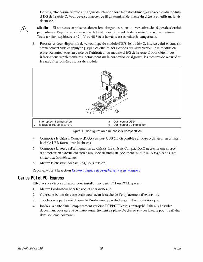
3. Pressez les deux dispositifs de verrouillage du module d’E/S de la série C, insérez celui-ci dans un emplacement vide et appuyez jusqu’à ce que les deux dispositifs aient verrouillé le module en place. Reportez-vous au guide de l’utilisateur du module d’E/S de la série C pour obtenir des informations supplémentaires, notamment sur la connexion de signaux, les mesures de sécurité et les spécifications électriques du module.
Figure 1. Configuration d’un châssis CompactDAQ
4. Connectez le châssis CompactDAQ à un port USB 2.0 disponible sur votre ordinateur en utilisant le câble USB fourni avec le châssis.
5. Connectez la source d’alimentation au châssis. Le châssis CompactDAQ nécessite une source d’alimentation externe conforme aux spécifications du document intitulé NI cDAQ-9172 User Guide and Specifications.
6. Mettez le châssis CompactDAQ sous tension.
Reportez-vous à la section Reconnaissance de périphérique sous Windows.
Cartes PCI et PCI ExpressEffectuez les étapes suivantes pour installer une carte PCI ou PCI Express :
1. Mettez l’ordinateur hors tension et débranchez-le.
2. Ouvrez le boîtier de votre ordinateur et/ou le cache de l’emplacement d’extension.
3. Touchez une partie métallique de l’ordinateur pour décharger l’électricité statique.
4. Insérez la carte dans l’emplacement système PCI/PCI Express approprié. Faites-la basculer doucement pour qu’elle se mette complètement en place. Ne forcez pas sur la carte pour l’enficher dans son emplacement.
1 Interrupteur d’alimentation 2 Module d’E/S de la série C
3 Connecteur USB4 Connecteur d’alimentation
NI cDAQ-9051
Ready
Active
11-30 VDC
2 A Max
OFF
ON
431
2
© National Instruments Corporation 17 Guide d’initiation DAQ
Figure 2. Installation d’une carte PCI/PCI Express
Conformément à la norme PCI, les cartes DAQ NI PCI qui possèdent un connecteur Universal PCI sont supportées par les bus conformes PCI, y compris PCI-X. Vous ne pouvez pas installer de cartes PCI Express dans des emplacements PCI et vice versa. Les cartes PCI Express peuvent être enfichées dans un emplacement PCI Express plus large. Sur certaines cartes mères, l’emplacement x16 est réservé aux cartes graphiques ; consultez les instructions du constructeur pour trouver d’autres solutions pour connecter une carte graphique si vous utilisez l’emplacement x16 pour une carte qui n’est pas une carte graphique. Pour obtenir des informations sur DAQ PCI Express, reportez-vous à ni.com/pciexpress/f.
5. Fixez le support de fixation de la carte au rail du panneau arrière de l’ordinateur.
6. (Facultatif) Sur les cartes NI PCI Express de la série M, comme les NI PCIe-6251/6259, branchez le connecteur d’alimentation du lecteur de disque du PC au connecteur d’alimentation du lecteur de disque de la carte. Reportez-vous au document intitulé M Series User Manual pour savoir quand utiliser le connecteur d’alimentation du lecteur de disque. L’alimentation disponible sur les connecteurs d’alimentation du lecteur de disque d’un ordinateur peut varier. Envisagez l’utilisation d’un connecteur d’alimentation de lecteur de disque qui ne se trouve pas dans la même chaîne d’alimentation que le disque dur. La chaîne d’alimentation est le faisceau de fils provenant de la source d’alimentation ; elle peut comporter plusieurs connecteurs pour disques durs.
Figure 3. Connexion de l’alimentation de lecteur de disque à la carte PCI Express
La connexion ou déconnexion du connecteur d’alimentation de lecteur de disque peut affecter les performances analogiques de votre carte. Pour éviter cela, NI vous recommande d’auto-étalonner la carte DAQ PCI Express dans MAX après avoir connecté ou déconnecté le connecteur d’alimentation du lecteur de disque. Vous obtiendrez des instructions à l’Étape 5. Confirmez que le périphérique est reconnu.
7. Refermez le boîtier de l’ordinateur.
8. Branchez votre ordinateur et mettez-le sous tension.
1 Carte DAQ PCI/PCI Express2 Emplacement système PCI/PCI Express
3 PC avec emplacement PCI/PCI Express
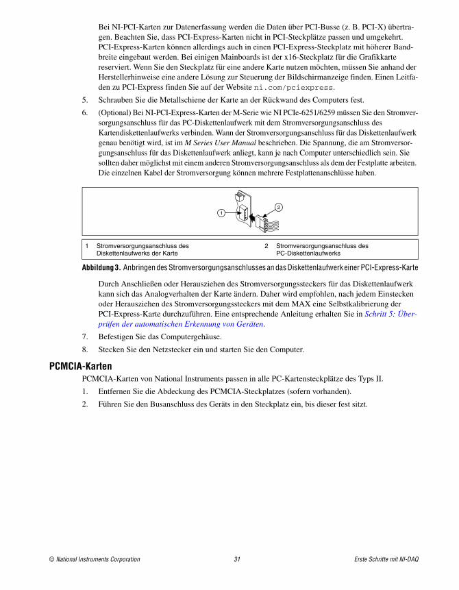
1 Connecteur d’alimentation de lecteur de disque de la carte
2 Connecteur d’alimentation de lecteur de disque du PC
3
12
12
Guide d’initiation DAQ 18 ni.com
Cartes PCMCIAVous pouvez installer une carte NI PCMCIA dans n’importe quel emplacement de carte PC de type II disponible.
1. Si nécessaire, retirez le cache de protection de l’emplacement PCMCIA.
2. Insérez le connecteur de bus PCMCIA de la carte PCMCIA dans l’emplacement jusqu’à ce que le connecteur soit maintenu fermement.
Figure 4. Installation d’une carte PCMCIA dans un ordinateur portable
3. Branchez le câble d’E/S. Prenez garde de ne pas tendre le câble d’E/S quand vous insérez ou retirez son connecteur. Saisissez toujours le câble par son connecteur quand vous le connectez ou l’enlevez. Ne tirez jamais directement sur le câble d’E/S pour débrancher la carte PCMCIA.
Périphériques PXI et PXI ExpressEffectuez les étapes suivantes pour installer le module PXI/PXIe.
1. Mettez le châssis PXI/PXIe hors tension et débranchez-le.
Attention Reportez-vous au document Read Me First: Safety and Radio-Frequency Interference livré avec votre châssis ou périphérique PXI/PXIe avant d’ouvrir le châssis, ou de connecter ou déconnecter des câbles de signal.
Figure 5. Installation d’un périphérique PXI/PXIe dans un châssis PXI/PXIe
1 Ordinateur doté d’un emplacement pour carte PC de type II
2 Socket pour carte PC de Type II
3 Carte PCMCIA4 Câble d’E/S blindé
5 Accessoire6 Lignes de signaux
1 Châssis PXI/PXIe2 Contrôleur système PXI/PXIe3 Module PXI/PXIe
4 Dispositif d’insertion/éjection5 Vis de montage du panneau avant
6 Guides pour module7 Interrupteur d’alimentation
®
®
DAQCard
1
2
34
56
3
2
4
PXI-1000B
7
56
1
© National Instruments Corporation 19 Guide d’initiation DAQ
2. Identifiez un emplacement PXI/PXIe supporté dans le châssis.
Figure 6. Symboles pour les emplacements PXIe/PXI Express hybride/PXI
Certains périphériques ont des spécifications précises en ce qui concerne l’emplacement PXI/PXIe ; pour en savoir plus, reportez-vous à la documentation du périphérique, comme cela est expliqué à l’Étape 2. Installez NI-DAQ.
Si vous utilisez un châssis PXIe, vous pouvez placer les périphériques PXI dans les emplacements PXI. Si un périphérique PXI est compatible avec les emplacements hybrides, vous pouvez aussi utiliser les emplacements PXI Express hybrides. Les périphériques PXIe ne peuvent être installés que dans les emplacements PXIe et PXI Express hybrides. Reportez-vous à la documentation du châssis PXIe pour obtenir de plus amples informations.
3. Retirez le cache de protection d’un emplacement PXI/PXIe vide.
4. Touchez une partie métallique du châssis pour décharger l’électricité statique.
5. Vérifiez que le dispositif d’insertion/éjection du module PXI/PXIe n’est pas verrouillé et n’offre aucune résistance lorsqu’il est actionné.
6. Placez les bords du module PXI/PXIe dans les guides de module en haut et en bas du châssis.
7. Faites glisser le périphérique dans l’emplacement PXI/PXIe à l’arrière du châssis.
8. Dès que vous sentez une résistance, relevez le dispositif d’insertion/éjection pour verrouiller le périphérique.
9. Vissez le périphérique sur le support de fixation situé à l’avant du châssis à l’aide des vis de montage.
10. Branchez le châssis PXI/PXIe et mettez-le sous tension.
Périphériques USBExécutez ces étapes pour installer un périphérique NI de type USB :
1. Effectuez les connexions d’alimentation.
• Si vous utilisez un pack batterie BP-1, suivez les instructions de votre guide d’installation BP-1.
• Certains périphériques NI de type USB nécessitent une alimentation externe. Si votre périphérique utilise une alimentation externe, assurez-vous que la tension sur le bloc d’alimentation externe, le cas échéant, est compatible avec le courant secteur dans votre région (120 ou 230 Vca) et avec la tension exigée par votre périphérique.
2. Connectez une extrémité du bloc d’alimentation ou du câble d’alimentation à une prise secteur et branchez l’autre extrémité au périphérique.
1 Emplacement de contrôleur système PXI Express2 Emplacement de périphérique PXI Express
3 Emplacement de périphérique PXI Express hybride4 Emplacement de cadencement système PXI Express
NI PXIe-1062Q
1 2 3 4
Guide d’initiation DAQ 20 ni.com
3. Connectez le câble branché dans le port USB de l’ordinateur ou tout autre hub à un port USB disponible du périphérique.
4. Si votre périphérique USB est équipé d’un bouton d’alimentation, mettez-le sous tension. L’ordinateur devrait détecter immédiatement votre périphérique.
Lorsque l’ordinateur reconnaît un périphérique USB, le témoin LED du périphérique clignote ou s’allume. Reportez-vous à la documentation sur le périphérique pour obtenir une explication des états de la LED.
Reconnaissance de périphérique sous WindowsWindows détecte et reconnaît tous les périphériques nouvellement installés au premier redémarrage qui suit l’installation. Sur certains systèmes Windows, l’Assistant Nouveau matériel détecté s’ouvre avec une boîte de dialogue pour chaque périphérique NI installé. Installer le logiciel automatiquement (Recommandé) est sélectionné par défaut. Cliquez sur Suivant ou sur Oui pour installer le logiciel de chaque périphérique.
Lorsque Windows a reconnu des périphériques USB NI nouvellement installés, y compris des périphériques CompactDAQ, une boîte de dialogue vous invite à sélectionner l’une des options suivantes, qui peuvent varier en fonction des périphériques et du logiciel installés sur le système :
• Commencer une mesure avec LabVIEW lance LabVIEW.
• Commencer une mesure en utilisant ce périphérique avec NI LabVIEW SignalExpress ouvre une étape DAQ qui utilise les voies de votre périphérique dans LabVIEW SignalExpress. Si vous avez installé un châssis CompactDAQ, une boîte de dialogue vous invite à sélectionner les modules à utiliser. Si vous avez des accessoires, des SCXI ou des capteurs à connecter et à configurer, reportez-vous à la section Accessoires ci-après et consultez les informations de l’Étape 5. Confirmez que le périphérique est reconnu à l’Étape 9. Exécutez les panneaux de test. Sinon, vous n’avez pas besoin de configurer de paramètres dans MAX. Reportez-vous à l’Étape 11. Utilisez NI-DAQmx avec votre logiciel d’application pour en savoir plus sur les prises de mesures DAQ dans LabVIEW SignalExpress.
• Configurer et tester ce périphérique ouvre MAX sur la page qui correspond à votre périphérique pour que vous puissiez définir les paramètres.
• Afficher les panneaux de test lance les panneaux de test MAX pour votre périphérique.
• Ne rien faire laisse votre périphérique dans le système mais ne lance pas d’application.
AccessoiresInstallez les accessoires et/ou les blocs de connexion en suivant les instructions fournies dans leurs guides d’installation respectifs. Pour les systèmes de conditionnement de signal SCXI et SCC, continuez à suivre les instructions de ce guide jusqu’à l’Étape 7. Installez les périphériques de conditionnement de signal ou de commutation.
Étape 5. Confirmez que le périphérique est reconnuSuivez ces étapes :
1. Double-cliquez sur l’icône Measurement & Automation qui se trouve sur le bureau pour ouvrir MAX.
© National Instruments Corporation 21 Guide d’initiation DAQ
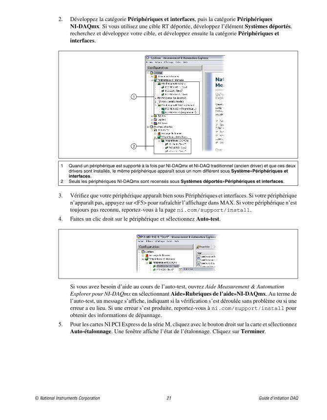
2. Développez la catégorie Périphériques et interfaces, puis la catégorie Périphériques NI-DAQmx. Si vous utilisez une cible RT déportée, développez l’élément Systèmes déportés, recherchez et développez votre cible, et développez ensuite la catégorie Périphériques et interfaces.
3. Vérifiez que votre périphérique apparaît bien sous Périphériques et interfaces. Si votre périphérique n’apparaît pas, appuyez sur <F5> pour rafraîchir l’affichage dans MAX. Si votre périphérique n’est toujours pas reconnu, reportez-vous à la page ni.com/support/install.
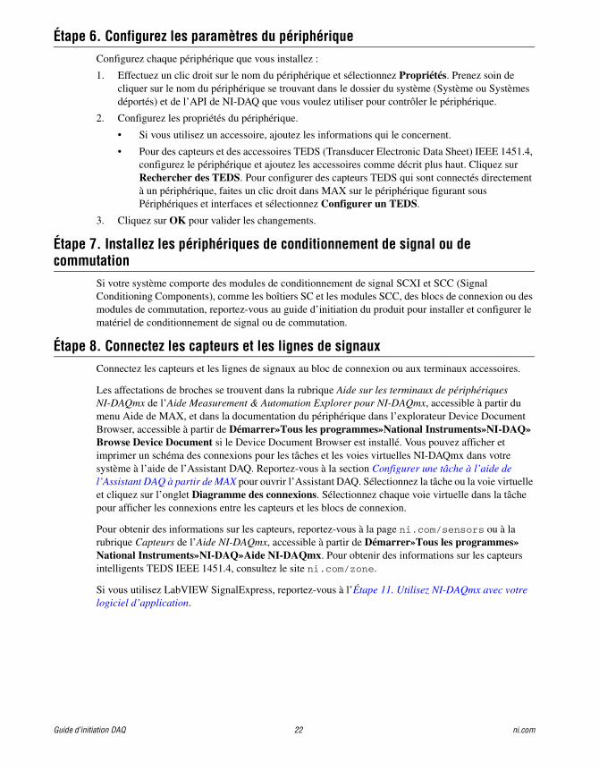
4. Faites un clic droit sur le périphérique et sélectionnez Auto-test.
Si vous avez besoin d’aide au cours de l’auto-test, ouvrez Aide Measurement & Automation Explorer pour NI-DAQmx en sélectionnant Aide»Rubriques de l’aide»NI-DAQmx. Au terme de l’auto-test, un message s’affiche, indiquant si la vérification s’est déroulée sans problème ou si une erreur a eu lieu. Si une erreur s’est produite, reportez-vous à ni.com/support/install pour obtenir des informations de dépannage.
5. Pour les cartes NI PCI Express de la série M, cliquez avec le bouton droit sur la carte et sélectionnez Auto-étalonnage. Une fenêtre affiche l’état de l’étalonnage. Cliquez sur Terminer.
1 Quand un périphérique est supporté à la fois par NI-DAQmx et NI-DAQ traditionnel (ancien driver) et que ces deux drivers sont installés, le même périphérique apparaît sous un nom différent sous Système»Périphériques et interfaces.
2 Seuls les périphériques NI-DAQmx sont recensés sous Systèmes déportés»Périphériques et interfaces.
1
2
Guide d’initiation DAQ 22 ni.com
Étape 6. Configurez les paramètres du périphériqueConfigurez chaque périphérique que vous installez :
1. Effectuez un clic droit sur le nom du périphérique et sélectionnez Propriétés. Prenez soin de cliquer sur le nom du périphérique se trouvant dans le dossier du système (Système ou Systèmes déportés) et de l’API de NI-DAQ que vous voulez utiliser pour contrôler le périphérique.
2. Configurez les propriétés du périphérique.
• Si vous utilisez un accessoire, ajoutez les informations qui le concernent.
• Pour des capteurs et des accessoires TEDS (Transducer Electronic Data Sheet) IEEE 1451.4, configurez le périphérique et ajoutez les accessoires comme décrit plus haut. Cliquez sur Rechercher des TEDS. Pour configurer des capteurs TEDS qui sont connectés directement à un périphérique, faites un clic droit dans MAX sur le périphérique figurant sous Périphériques et interfaces et sélectionnez Configurer un TEDS.
3. Cliquez sur OK pour valider les changements.
Étape 7. Installez les périphériques de conditionnement de signal ou de commutation
Si votre système comporte des modules de conditionnement de signal SCXI et SCC (Signal Conditioning Components), comme les boîtiers SC et les modules SCC, des blocs de connexion ou des modules de commutation, reportez-vous au guide d’initiation du produit pour installer et configurer le matériel de conditionnement de signal ou de commutation.
Étape 8. Connectez les capteurs et les lignes de signauxConnectez les capteurs et les lignes de signaux au bloc de connexion ou aux terminaux accessoires.
Les affectations de broches se trouvent dans la rubrique Aide sur les terminaux de périphériques NI-DAQmx de l’Aide Measurement & Automation Explorer pour NI-DAQmx, accessible à partir du menu Aide de MAX, et dans la documentation du périphérique dans l’explorateur Device Document Browser, accessible à partir de Démarrer»Tous les programmes»National Instruments»NI-DAQ»Browse Device Document si le Device Document Browser est installé. Vous pouvez afficher et imprimer un schéma des connexions pour les tâches et les voies virtuelles NI-DAQmx dans votre système à l’aide de l’Assistant DAQ. Reportez-vous à la section Configurer une tâche à l’aide de l’Assistant DAQ à partir de MAX pour ouvrir l’Assistant DAQ. Sélectionnez la tâche ou la voie virtuelle et cliquez sur l’onglet Diagramme des connexions. Sélectionnez chaque voie virtuelle dans la tâche pour afficher les connexions entre les capteurs et les blocs de connexion.
Pour obtenir des informations sur les capteurs, reportez-vous à la page ni.com/sensors ou à la rubrique Capteurs de l’Aide NI-DAQmx, accessible à partir de Démarrer»Tous les programmes»National Instruments»NI-DAQ»Aide NI-DAQmx. Pour obtenir des informations sur les capteurs intelligents TEDS IEEE 1451.4, consultez le site ni.com/zone.
Si vous utilisez LabVIEW SignalExpress, reportez-vous à l’Étape 11. Utilisez NI-DAQmx avec votre logiciel d’application.
© National Instruments Corporation 23 Guide d’initiation DAQ
Étape 9. Exécutez les panneaux de testDe nombreux périphériques comportent un panneau de test pour tester des fonctionnalités spécifiques à ce périphérique, par exemple sa capacité d’acquisition ou de génération de signaux.
1. Dans MAX, développez la catégorie Périphériques et interfaces»Périphériques NI-DAQmx. Si vous utilisez une cible RT déportée, développez l’élément Systèmes déportés, recherchez et développez votre cible, et développez ensuite la catégorie Périphériques et interfaces.
2. Cliquez avec le bouton droit sur le périphérique à tester.
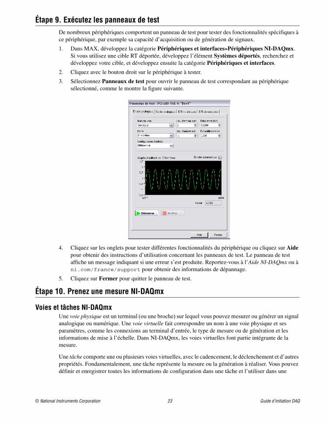
3. Sélectionnez Panneaux de test pour ouvrir le panneau de test correspondant au périphérique sélectionné, comme le montre la figure suivante.
4. Cliquez sur les onglets pour tester différentes fonctionnalités du périphérique ou cliquez sur Aide pour obtenir des instructions d’utilisation concernant les panneaux de test. Le panneau de test affiche un message indiquant si une erreur s’est produite. Reportez-vous à l’Aide NI-DAQmx ou à ni.com/france/support pour obtenir des informations de dépannage.
5. Cliquez sur Fermer pour quitter le panneau de test.
Étape 10. Prenez une mesure NI-DAQmx
Voies et tâches NI-DAQmx Une voie physique est un terminal (ou une broche) sur lequel vous pouvez mesurer ou générer un signal analogique ou numérique. Une voie virtuelle fait correspondre un nom à une voie physique et ses paramètres, comme les connexions au terminal d’entrée, le type de mesure ou de génération et les informations de mise à l’échelle. Dans NI-DAQmx, les voies virtuelles font partie intégrante de la mesure.
Une tâche comporte une ou plusieurs voies virtuelles, avec le cadencement, le déclenchement et d’autres propriétés. Fondamentalement, une tâche représente la mesure ou la génération à réaliser. Vous pouvez définir et enregistrer toutes les informations de configuration dans une tâche et l’utiliser dans une
Guide d’initiation DAQ 24 ni.com
application. Reportez-vous à l'Aide NI-DAQmx pour obtenir toutes les informations sur les voies et les tâches.
Avec NI-DAQmx, vous utilisez l’Assistant DAQ pour configurer des voies virtuelles et des tâches dans MAX ou dans votre logiciel d’application.
Configurer une tâche à l’aide de l’Assistant DAQ à partir de MAXEffectuez les étapes suivantes pour créer une tâche à l’aide de l’Assistant DAQ dans MAX :
1. Dans MAX, faites un clic droit sur Voisinage de données et sélectionnez Créer un nouvel objet pour ouvrir l’Assistant DAQ.
2. Dans la fenêtre Créer un nouvel objet, sélectionnez Tâche NI-DAQmx, puis cliquez sur Suivant.
3. Sélectionnez Acquérir des signaux ou Générer des signaux.
4. Sélectionnez le type d’E/S, comme par exemple, entrée analogique, et le type de mesure, comme une tension.
5. Sélectionnez la ou les voies physiques à utiliser et cliquez sur Suivant.
6. Nommez la tâche et cliquez sur Terminer.
7. Configurez les paramètres de chaque voie. Un nom de voie virtuelle est attribué à chaque voie physique que vous assignez à une tâche. Pour modifier la gamme d’entrée ou d’autres paramètres, sélectionnez la voie. Cliquez sur Afficher les détails pour obtenir des informations sur la voie physique. Configurez les informations de cadencement et de déclenchement pour votre tâche. Cliquez sur Tester.
Étape 11. Utilisez NI-DAQmx avec votre logiciel d’applicationVous pouvez utiliser l’Assistant DAQ avec la version 7.x ou une version ultérieure de LabVIEW, LabWindows/CVI ou Measurement Studio, ou avec la version 2.x ou une version ultérieure de LabVIEW SignalExpress.
Les CD NI-DAQmx intègrent LabVIEW SignalExpress LE, un outil facile à utiliser basé sur configuration et conçu spécifiquement pour les applications d’enregistrement de données. L’application est disponible à partir de Démarrer»Tous les programmes»National Instruments»LabVIEW SignalExpress. L’Aide LabVIEW SignalExpress est disponible à partir de LabVIEW SignalExpress sous Aide»LabVIEW SignalExpress.
Pour commencer à utiliser votre logiciel d’application, reportez-vous aux tutoriels :
• Le tutoriel Assistant DAQ LabVIEW se trouve dans LabVIEW sous Aide»Initiation à LabVIEW»Initiation à DAQ»Prendre une mesure NI-DAQmx dans LabVIEW.
• Le tutoriel Assistant DAQ LabWindows/CVI se trouve dans LabWindows/CVI sous Help»Help Topics»Taking an NI-DAQmx Measurement in LabWindows/CVI.
• Le tutoriel DAQ Assistant Measurement Studio se trouve sous Measurement Studio»NI Measurement Studio Help»Getting Started with the Measurement Studio Class Libraries»Measurement Studio Walkthroughs»Walkthrough: Creating a Measurement Studio NI-DAQmx Application.
• Le tutoriel Assistant DAQ LabVIEW SignalExpress se trouve dans LabVIEW SignalExpress sous Aide»Initiation à»Prendre une mesure NI-DAQmx dans LabVIEW SignalExpress.
© National Instruments Corporation 25 Guide d’initiation DAQ
ExemplesVous pouvez utiliser les exemples pour développer une nouvelle application ou ajouter le code des exemples dans une application existante.
Pour consulter d’autres exemples, visitez le site ni.com/zone. Pour exécuter des exemples sans matériel installé, vous pouvez utiliser un périphérique simulé NI-DAQmx. Dans MAX, reportez-vous à l’Aide Measurement & Automation Explorer pour NI-DAQmx en sélectionnant Aide»Rubriques de l’aide»NI-DAQmx pour obtenir des informations sur la création de périphériques simulés NI-DAQmx.
Informations supplémentairesAprès l’installation de la documentation sur les périphériques, vous pouvez accéder à l’explorateur et à la documentation des périphériques à partir de Démarrer»Tous les programmes»National Instruments»NI-DAQ»Browse Device Documentation. Les documents sur le logiciel NI-DAQ, comme l’Aide NI-DAQmx et le Guide d’initiation DAQ, sont disponibles à partir de Démarrer»Tous les programmes»National Instruments»NI-DAQ»titre du document NI-DAQmx.
Vous pouvez aussi accéder à la documentation en ligne concernant le périphérique en cliquant avec le bouton droit sur votre périphérique dans MAX et en sélectionnant Aide»Documentation en ligne sur les périphériques. La page ni.com/manuals s’ouvre et vous donne les résultats de la recherche sur les documents se rapportant à votre périphérique. Le site Web ni.com/manuals comprend aussi des documents pour les périphériques qui sont sortis depuis la dernière version de NI-DAQmx et de nouvelles versions de la documentation qui ne sont pas encore disponibles sur le navigateur de documents de périphériques NI-DAQ.
DépannageUtilisez les ressources suivantes si vous vous heurtez à des problèmes lors de l’installation de votre matériel et/ou logiciel DAQ :
• Pour consulter des instructions de dépannage, reportez-vous à la rubrique Hardware Installation / Configuration Troubleshooter sur ni.com/support/install.
• Reportez-vous à ni.com/kb pour accéder aux documents se rapportant au dépannage des problèmes courants d’installation et de programmation, et pour obtenir les réponses aux questions les plus fréquentes concernant les produits NI.
Application logicielle Emplacement des exemples
LabVIEW ou LabWindows/CVI Aide»Recherche d'exemples
LabVIEW SignalExpress Program Files\National Instruments\SignalExpress\Examples
ANSI C NI-DAQ\Examples\DAQmx ANSI C
Langages supportés par Measurement Studio
MFC 7.0 C++ NI-DAQ\Examples\MStudioVC2003
Exemples Visual Basic .NET et C# pour Visual Studio 2003* NI-DAQ\Examples\DotNET1.1
MFC 8,0 C++ NI-DAQ\Examples\MStudioVC2005
Exemples Visual Basic .NET et C# pour Visual Studio 2005* NI-DAQ\Examples\DotNET2.0
* Measurement Studio n'est pas exigé
National Instruments, NI, ni.com et LabVIEW sont des marques de National Instruments Corporation. Pour plus d’informations concernant les marques de National Instruments, veuillez vous référer à la partie Terms of Use sur le site ni.com/legal. Les autres noms de produits et de sociétés mentionnés aux présentes sont les marques ou les noms de leurs propriétaires respectifs. Pour la liste des brevets protégeant les produits National Instruments, veuillez vous référer, selon le cas : à la rubrique Aide»Brevets de votre logiciel, au fichier patents.txt sur votre CD, ou à ni.com/patents.
© 2003–2007 National Instruments Corporation. Tous droits réservés. 373235M Jui07
• Si vous pensez avoir endommagé votre périphérique et que vous jugez devoir renvoyer votre matériel National Instruments pour le faire réparer ou étalonner, rendez-vous sur ni.com/france et entrez rdfcon dans le champ info code pour contacter votre filiale afin de savoir comment procéder pour obtenir une autorisation de renvoi de marchandise.
Support technique dans le monde entierPour obtenir un support complémentaire, visitez le site ni.com/france/support ou ni.com/zone. Pour obtenir des informations de support supplémentaires sur les produits de conditionnement de signal, reportez-vous au document Signal Conditioning Technical Support Information fourni avec votre périphérique.
Le siège social de National Instruments est situé à l’adresse suivante : 11500 North Mopac Expressway, Austin, Texas, 78759-3504, États-Unis. National Instruments compte aussi des filiales dans le monde entier pour répondre à vos besoins de support.
Erste Schritte mit NI-DAQDiese Broschüre beschreibt, wie Datenerfassungshardware angeschlossen und getestet wird und wie der Treiber NI-DAQmx für Windows installiert wird. Zur Installation des Treibers unter Linux lesen Sie bitte die NI-DAQmx for Linux Readme auf ni.com/downloads. Die Konfiguration des traditionellen NI-DAQ-Treibers ist in der Readme zum traditionellen NI-DAQ-Treiber beschrieben, die nach der Installation des Treibers über Start»Alle Programme»National Instruments»NI-DAQ geöffnet werden kann.
NI-DAQ-SoftwareAlle messtechnischen Geräte von National Instruments, wie Multifunktions-I/O-Karten der M-Serie, werden mit dem NI-DAQ-Treiber geliefert. Dieser Treiber enthält eine umfangreiche Bibliothekvon VIs sowie ANSI-C und .NET-Funktionen für Entwicklungsumgebungen wie NI LabVIEW, NI LabWindows™/CVI™, Microsoft Visual Studio .NET oder NI Signal Express. Zum Treiber gehört eine API in Form einer Bibliothek von VIs, Funktionen, Klassen, Attributen und Eigenschaften, mit der Sie Anwendungen für Ihre Messgeräte erstellen können.
NI-DAQ ab 7.x besteht aus zwei Treibern mit eigener API und Konfiguration. NI-DAQmx ist der neuere der beiden Treiber. Er weist gegenüber dem traditionellen NI-DAQ-Treiber folgende Vorteile auf:
• Zu NI-DAQmx gehört ein so genannter DAQ-Assistent. Darin können Sie virtuelle Kanäle und Tasks für Messungen mit einem Gerät konfigurieren und in Programmcode für LabVIEW, LabWindows/CVI, Measurement Studio, VI Logger, LabVIEW SignalExpress und den Measurement & Automation Explorer umwandeln.
• Leistungsfähigere Funktionen, zum Beispiel schnellere Ein- und Ausgabe einzelner Werte oder Multithreading.
• Simulationsmöglichkeit der meisten von NI-DAQmx unterstützten Geräte (die genaue Liste finden Sie in der NI-DAQ Readme), so dass Sie Ihre Anwendungen ohne angeschlossene Hardware testen können.
• Einfachere, intuitiver gestaltete Programmieroberfläche, die mit weniger VIs und Funktionen als frühere NI-DAQ-Versionen auskommt.
Der traditionelle NI-DAQ-Treiber ist ein älterer Treiber, der nur noch mit einzelnen DAQ-Karten von National Instruments arbeitet. Sie sollten den traditionellen NI-DAQ nur unter bestimmten Umständen verwenden. Einzelheiten dazu finden Sie in der NI-DAQ Readme, die auch eine Übersicht der Geräte, Betriebssysteme, Entwicklungsumgebungen und Programmiersprachen enthält, die mit dem Treiber kompatibel sind. Der traditionelle NI-DAQ-Treiber kann bei Bedarf von ni.com/downloads herun-tergeladen werden.
Schritt 1: Installieren der EntwicklungsumgebungInstallieren Sie Ihre Entwicklungsumgebung von National Instruments. NI-DAQmx arbeitet mit LabVIEW, LabWindows/CVI und Measurement Studio (jeweils ab 7.x), LabVIEW SignalExpress ab 2.x und dem LabVIEW Real-Time Module ab 7.1. Legen Sie von Anwendungen, die mit einer älteren Entwicklungsumgebung von National Instruments oder einer älteren Version des NI-DAQ-Treibers erstellt wurden, eine Sicherungskopie an, so dass sie nach dem Upgrade des Treibers ohne Risiko ver-ändert werden können.
Erste Schritte mit NI-DAQ 28 ni.com
Schritt 2: Installieren von NI-DAQInstallieren Sie den Treiber immer vor dem Anschließen neuer Geräte, da die Geräte sonst nicht auto-matisch erkannt werden. Installieren Sie NI-DAQ nicht, wenn in Ihren Anwendungen Komponenten enthalten sind, die von diesem Treiber nicht unterstützt werden (siehe dazu die NI-DAQ-Readme).
Vorsicht! NI-DAQ-Versionen ab 7.x dürfen nicht zusammen mit älteren NI-DAQ-Versionen instal-liert werden.
1. Legen Sie die CD 1 ein. Der Installationsassistent sollte sich automatisch öffnen. Wenn nicht, wählen Sie Start»Ausführen und geben Sie x:\autorun.exe ein (x steht für den Buchstaben des CD-Laufwerks). Bei Problemen besuchen Sie bitte unsere Website ni.com/support/install und gehen Sie nach den Anweisungen im “Hardware Installation/Configuration Troubleshooter” vor.
2. Installieren Sie die Software.
• Mit Software installieren wird die Software und Dokumentation auf die Festplatte kopiert. Die Dokumentation zu NI-DAQ wird automatisch zusammen mit dem Treiber installiert.
• Mit ReadMe-Datei anzeigen wird die Readme geöffnet.
• Mit CD durchsuchen gelangen Sie zur Dokumentation der Hardware, wo Sie nach Themen suchen und diese ausdrucken können.
Der NI-DAQ-Installationsassistent erkennt automatisch die auf dem Computer vorhandene Software von National Instruments und wählt die neueste Version des Treibers, der Entwicklungs-umgebung oder der Hilfsdateien für Programmiersprachen von der CD aus. Überprüfen Sie, ob die automatische Auswahl korrekt ist. Wenn Sie Entwicklungsumgebungen von National Instruments im Anschluss an NI-DAQ installieren, muss das NI-DAQ-Installationsprogramm noch einmal gestartet werden, damit die fehlenden Hilfsdateien hinzugefügt werden.
3. Folgen Sie den Eingabeaufforderungen. Unter Windows Vista kann es bei der Installation zu Zugriffs- und Sicherheitswarnungen kommen. Folgen Sie den Anweisungen.
4. Nach dem Ende der Installation werden verschiedene Dialogfelder angezeigt. Zum Abschließen der Installation klicken Sie auf Weiter.
5. Daraufhin öffnet sich das letzte Dialogfeld mit den folgenden Optionen:
• Zum Installieren weiterer Software von National Instruments wählen Sie Neustart später.
– Sie können auch die PDF- und Hilfedateien der Geräte, für die der Treiber vorgesehen ist, auf Ihren Rechner kopieren. Darin sind die technischen Daten sowie die Pinbelegun-gen, Leistungsmerkmale und Informationen zur Betriebsweise der Geräte enthalten. Legen Sie dazu die CD 2 mit der Beschriftung “Device Documentation” ein und öffnen Sie das Begrüßungsfenster. Wählen Sie Install Device Documentation.
– Wenn Ihr PC über eine MXI-3-Schnittstelle mit einem PXI-Chassis verbunden ist, ver-lassen Sie das Programm und installieren Sie die MXI-3-Software, die bei Bedarf auch von der Website ni.com/downloads heruntergeladen werden kann.
• Herunterfahren oder Neustart sollte ausgewählt werden, wenn alles zum Anschließen der Geräte bereit ist.
• Bei Systemen mit dem LabVIEW Real-Time Module wählen Sie Neustart. Übertragen Sie dann NI-DAQ mithilfe des MAX auf das RT-System. Die Vorgehensweise dazu ist in der Measurement & Automation Explorer-Hilfe zu Systemen im Netzwerk beschrieben, die im MAX über Hilfe»Hilfethemen»Netzwerkumgebung aufgerufen wird.
© National Instruments Corporation 29 Erste Schritte mit NI-DAQ
Schritt 3: Auspacken der Geräte, Zusatzbauteile und KabelPacken Sie die Karte aus und überprüfen Sie, ob sich Teile davon gelöst haben oder die Karte anderwei-tig beschädigt ist. Sollte die Karte schadhaft erscheinen, setzen Sie sich bitte mit uns in Verbindung. Bauen Sie auf keinen Fall eine defekte Karte ein!
Sicherheitshinweise und Informationen zur Einhaltung von Sicherheitsstandards finden Sie auf ni.com/manuals und in der Dokumentation, die nach Abschluss der Installation über Start»Alle Programme»National Instruments»NI-DAQ»Browse Device Documentation geöffnetwerden kann.
Auf Ihrem Gerät können folgende Symbole aufgedruckt sein:
Mit diesem Symbol wird vor Datenverlust, Systemabsturz und Verletzungen gewarnt. Welche Vorsichts-maßnahmen bei Produkten mit diesem Symbol zu treffen sind, wird im Faltblatt Read Me First: Safety and Radio-Frequency Interference in der Packungsbeilage erläutert.
Wenn ein Produkt mit diesem Symbol gekennzeichnet ist, besteht die Gefahr eines elektrischen Schlags.
Bei Produkten mit diesem Symbol kann eines der Bauteile heiß werden. Bei Berührung besteht Verletzungsgefahr.
Schritt 4: Anschließen der einzelnen KomponentenBauen Sie nun alle vorhandenen DAQ-Geräte wie in diesem Kapitel beschrieben ein. SCXI-Module werden im Anschluss an die DAQ-Komponenten angeschlossen.
Vorsicht! Vor dem Einbauen von Hardware ist unbedingt eine Erdung gemäß VDE erforderlich. Alle Sicherheitsinformationen zu Ihrer Hardware finden Sie auf dem mitgelieferten Datenblatt.
Mit der Simulationsfunktion in NI-DAQmx können Sie NI-DAQmx-Applikationen auch ohne ange-schlossene Hardware testen. Lesen Sie dazu auch die Hilfe zum Measurement & Automation Explorer für NI-DAQmx, die im MAX über Hilfe»Hilfethemen»NI-DAQmx geöffnet wird.
CompactDAQI/O-Module der C-Serie werden nach folgenden Schritten eingebaut:
1. Schalten Sie das CompactDAQ-Chassis aus.
2. Wenn Sie kein Montagezubehör verwenden, befestigen Sie die mitgelieferte Gummiisolierung an der Rückseite des CompactDAQ-Chassis. Bringen Sie an einem 1,6 mm dicken Draht einen Kabel-schuh an. Schrauben Sie den Kabelschuh mit der mitgelieferten Schraube am Masseanschluss an der Seite des Chassis fest. Verbinden Sie das andere Ende des Drahts mit Masse.
Schließen Sie außerdem mit Hilfe eines Kabelschuhs einen Draht an die Kabelabschirmungen der Module an. Dieser Draht muss mit der mitgelieferten Schraube ebenfalls am Masseanschluss des Chassis befestigt werden.
Vorsicht! Bei gefährlichen Spannungen gelten bestimmte Sicherheitsrichtlinien. Lesen Sie in diesem Fall die Bedienungsanleitung des Geräts. Als gefährlich gelten Wechselspannungen über 42,4 V und Gleichspannungen von mehr als 60 V gegenüber Erde.
3. Drücken Sie beide Hebel des Moduls nach unten, schieben Sie es in einen leeren Steckplatz und drücken Sie, bis es einrastet. Die Anschlüsse für die Signalleitungen, die geltenden Sicherheitsbe-stimmungen und die Modulkategorien sind in der Bedienungsanleitung des Moduls beschrieben.
Erste Schritte mit NI-DAQ 30 ni.com
.
Abbildung 1. Einrichten eines CompactDAQ-Chassis
4. Schließen Sie das CompactDAQ-Chassis mit dem mitgelieferten USB-Kabel an einen beliebigen USB-Anschluss des Computers an.
5. Stecken Sie den Netzstecker des Chassis ein. Für das CompactDAQ-Chassis wird ein Netzteil benötigt, das den Spezifikationen im Dokument NI cDAQ-9172 User Guide and Specifications entspricht.
6. Schalten Sie das CompactDAQ-Chassis ein.
Siehe dazu den Abschnitt Erkennung von Geräten unter Windows.
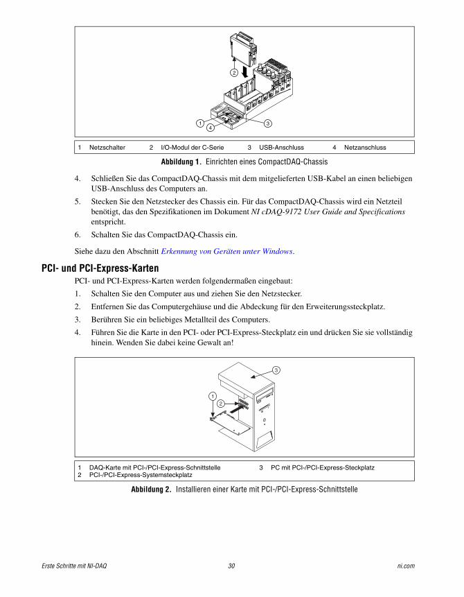
PCI- und PCI-Express-KartenPCI- und PCI-Express-Karten werden folgendermaßen eingebaut:
1. Schalten Sie den Computer aus und ziehen Sie den Netzstecker.
2. Entfernen Sie das Computergehäuse und die Abdeckung für den Erweiterungssteckplatz.
3. Berühren Sie ein beliebiges Metallteil des Computers.
4. Führen Sie die Karte in den PCI- oder PCI-Express-Steckplatz ein und drücken Sie sie vollständig hinein. Wenden Sie dabei keine Gewalt an!
Abbildung 2. Installieren einer Karte mit PCI-/PCI-Express-Schnittstelle
1 Netzschalter 2 I/O-Modul der C-Serie 3 USB-Anschluss 4 Netzanschluss
1 DAQ-Karte mit PCI-/PCI-Express-Schnittstelle2 PCI-/PCI-Express-Systemsteckplatz
3 PC mit PCI-/PCI-Express-Steckplatz
NI cDAQ-9051
Ready
Active
11-30 VDC
2 A Max
OFF
ON
431
2
3
12
© National Instruments Corporation 31 Erste Schritte mit NI-DAQ
Bei NI-PCI-Karten zur Datenerfassung werden die Daten über PCI-Busse (z. B. PCI-X) übertra-gen. Beachten Sie, dass PCI-Express-Karten nicht in PCI-Steckplätze passen und umgekehrt. PCI-Express-Karten können allerdings auch in einen PCI-Express-Steckplatz mit höherer Band-breite eingebaut werden. Bei einigen Mainboards ist der x16-Steckplatz für die Grafikkarte reserviert. Wenn Sie den Steckplatz für eine andere Karte nutzen möchten, müssen Sie anhand der Herstellerhinweise eine andere Lösung zur Steuerung der Bildschirmanzeige finden. Einen Leitfa-den zu PCI-Express finden Sie auf der Website ni.com/pciexpress.
5. Schrauben Sie die Metallschiene der Karte an der Rückwand des Computers fest.
6. (Optional) Bei NI-PCI-Express-Karten der M-Serie wie NI PCIe-6251/6259 müssen Sie den Stromver-sorgungsanschluss für das PC-Diskettenlaufwerk mit dem Stromversorgungsanschluss des Kartendiskettenlaufwerks verbinden. Wann der Stromversorgungsanschluss für das Diskettenlaufwerk genau benötigt wird, ist im M Series User Manual beschrieben. Die Spannung, die am Stromversor-gungsanschluss für das Diskettenlaufwerk anliegt, kann je nach Computer unterschiedlich sein. Sie sollten daher möglichst mit einem anderen Stromversorgungsanschluss als dem der Festplatte arbeiten. Die einzelnen Kabel der Stromversorgung können mehrere Festplattenanschlüsse haben.
Abbildung 3. Anbringen des Stromversorgungsanschlusses an das Diskettenlaufwerk einer PCI-Express-Karte
Durch Anschließen oder Herausziehen des Stromversorgungssteckers für das Diskettenlaufwerk kann sich das Analogverhalten der Karte ändern. Daher wird empfohlen, nach jedem Einstecken oder Herausziehen des Stromversorgungssteckers mit dem MAX eine Selbstkalibrierung der PCI-Express-Karte durchzuführen. Eine entsprechende Anleitung erhalten Sie in Schritt 5: Über-prüfen der automatischen Erkennung von Geräten.
7. Befestigen Sie das Computergehäuse.
8. Stecken Sie den Netzstecker ein und starten Sie den Computer.
PCMCIA-KartenPCMCIA-Karten von National Instruments passen in alle PC-Kartensteckplätze des Typs II.
1. Entfernen Sie die Abdeckung des PCMCIA-Steckplatzes (sofern vorhanden).
2. Führen Sie den Busanschluss des Geräts in den Steckplatz ein, bis dieser fest sitzt.
1 Stromversorgungsanschluss des Diskettenlaufwerks der Karte
2 Stromversorgungsanschluss des PC-Diskettenlaufwerks
12
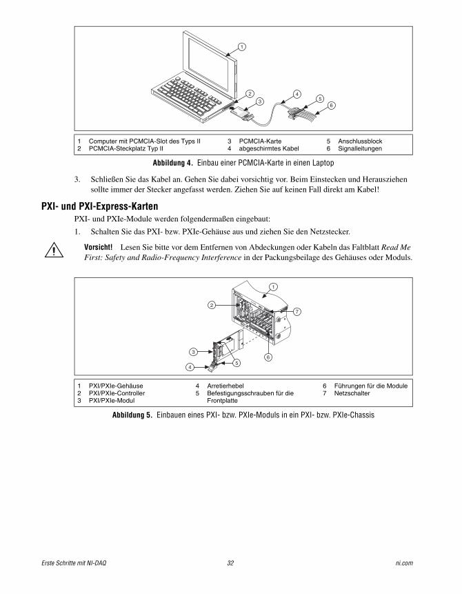
Erste Schritte mit NI-DAQ 32 ni.com
Abbildung 4. Einbau einer PCMCIA-Karte in einen Laptop
3. Schließen Sie das Kabel an. Gehen Sie dabei vorsichtig vor. Beim Einstecken und Herausziehen sollte immer der Stecker angefasst werden. Ziehen Sie auf keinen Fall direkt am Kabel!
PXI- und PXI-Express-KartenPXI- und PXIe-Module werden folgendermaßen eingebaut:
1. Schalten Sie das PXI- bzw. PXIe-Gehäuse aus und ziehen Sie den Netzstecker.
Vorsicht! Lesen Sie bitte vor dem Entfernen von Abdeckungen oder Kabeln das Faltblatt Read Me First: Safety and Radio-Frequency Interference in der Packungsbeilage des Gehäuses oder Moduls.
Abbildung 5. Einbauen eines PXI- bzw. PXIe-Moduls in ein PXI- bzw. PXIe-Chassis
1 Computer mit PCMCIA-Slot des Typs II2 PCMCIA-Steckplatz Typ II
3 PCMCIA-Karte4 abgeschirmtes Kabel
5 Anschlussblock6 Signalleitungen
1 PXI/PXIe-Gehäuse2 PXI/PXIe-Controller3 PXI/PXIe-Modul
4 Arretierhebel5 Befestigungsschrauben für die
Frontplatte
6 Führungen für die Module7 Netzschalter
®
®
DAQCard
1
2
34
56
3
2
4
PXI-1000B
7
56
1
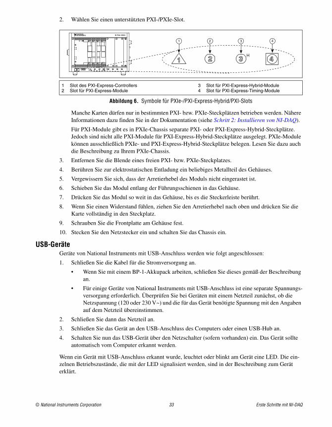
© National Instruments Corporation 33 Erste Schritte mit NI-DAQ
2. Wählen Sie einen unterstützten PXI-/PXIe-Slot.
Abbildung 6. Symbole für PXIe-/PXI-Express-Hybrid/PXI-Slots
Manche Karten dürfen nur in bestimmten PXI- bzw. PXIe-Steckplätzen betrieben werden. Nähere Informationen dazu finden Sie in der Dokumentation (siehe Schritt 2: Installieren von NI-DAQ).
Für PXI-Module gibt es in PXIe-Chassis separate PXI- oder PXI-Express-Hybrid-Steckplätze. Jedoch sind nicht alle PXI-Module für PXI-Express-Hybrid-Steckplätze ausgelegt. PXIe-Module können ausschließlich PXIe- und PXI-Express-Hybrid-Steckplätze belegen. Lesen Sie dazu auch die Beschreibung zu Ihrem PXIe-Chassis.
3. Entfernen Sie die Blende eines freien PXI- bzw. PXIe-Steckplatzes.
4. Berühren Sie zur elektrostatischen Entladung ein beliebiges Metallteil des Gehäuses.
5. Vergewissern Sie sich, dass der Arretierhebel des Moduls nicht eingerastet ist.
6. Schieben Sie das Modul entlang der Führungsschienen in das Gehäuse.
7. Drücken Sie das Modul so weit in das Gehäuse, bis es die Steckerleiste berührt.
8. Wenn Sie einen Widerstand fühlen, ziehen Sie den Arretierhebel nach oben und drücken Sie die Karte vollständig in den Steckplatz.
9. Schrauben Sie die Frontplatte am Gehäuse fest.
10. Stecken Sie den Netzstecker ein und schalten Sie das Chassis ein.
USB-GeräteGeräte von National Instruments mit USB-Anschluss werden wie folgt angeschlossen:
1. Schließen Sie die Kabel für die Stromversorgung an.
• Wenn Sie mit einem BP-1-Akkupack arbeiten, schließen Sie dieses gemäß der Beschreibung an.
• Für einige Geräte von National Instruments mit USB-Anschluss ist eine separate Spannungs-versorgung erforderlich. Überprüfen Sie bei Geräten mit einem Netzteil zunächst, ob die Netzspannung (120 oder 230 V~) und die für das Gerät benötigte Spannung mit den Angaben auf dem Netzteil übereinstimmen.
2. Schließen Sie dann das Netzteil an.
3. Schließen Sie das Gerät an den USB-Anschluss des Computers oder einen USB-Hub an.
4. Schalten Sie nun das USB-Gerät über den Netzschalter (sofern vorhanden) ein. Das Gerät sollte automatisch vom Computer erkannt werden.
Wenn ein Gerät mit USB-Anschluss erkannt wurde, leuchtet oder blinkt am Gerät eine LED. Die ein-zelnen Betriebszustände, die mit der LED signalisiert werden, sind in der Beschreibung zum Gerät erklärt.
1 Slot des PXI-Express-Controllers2 Slot für PXI-Express-Module
3 Slot für PXI-Express-Hybrid-Module4 Slot für PXI-Express-Timing-Module
NI PXIe-1062Q
1 2 3 4
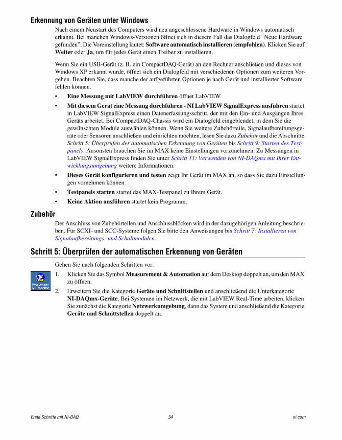
Erste Schritte mit NI-DAQ 34 ni.com
Erkennung von Geräten unter WindowsNach einem Neustart des Computers wird neu angeschlossene Hardware in Windows automatisch erkannt. Bei manchen Windows-Versionen öffnet sich in diesem Fall das Dialogfeld “Neue Hardware gefunden”. Die Voreinstellung lautet: Software automatisch installieren (empfohlen). Klicken Sie auf Weiter oder Ja, um für jedes Gerät einen Treiber zu installieren.
Wenn Sie ein USB-Gerät (z. B. ein CompactDAQ-Gerät) an den Rechner anschließen und dieses von Windows XP erkannt wurde, öffnet sich ein Dialogfeld mit verschiedenen Optionen zum weiteren Vor-gehen. Beachten Sie, dass manche der aufgeführten Optionen je nach Gerät und installierter Software fehlen können.
• Eine Messung mit LabVIEW durchführen öffnet LabVIEW.
• Mit diesem Gerät eine Messung durchführen - NI LabVIEW SignalExpress ausführen startet in LabVIEW SignalExpress einen Datenerfassungsschritt, der mit den Ein- und Ausgängen Ihres Geräts arbeitet. Bei CompactDAQ-Chassis wird ein Dialogfeld eingeblendet, in dem Sie die gewünschten Module auswählen können. Wenn Sie weitere Zubehörteile, Signalaufbereitungsge-räte oder Sensoren anschließen und einrichten möchten, lesen Sie dazu Zubehör und die Abschnitte Schritt 5: Überprüfen der automatischen Erkennung von Geräten bis Schritt 9: Starten des Test-panels. Ansonsten brauchen Sie im MAX keine Einstellungen vorzunehmen. Zu Messungen in LabVIEW SignalExpress finden Sie unter Schritt 11: Verwenden von NI-DAQmx mit Ihrer Ent-wicklungsumgebung weitere Informationen.
• Dieses Gerät konfigurieren und testen zeigt Ihr Gerät im MAX an, so dass Sie dazu Einstellun-gen vornehmen können.
• Testpanels starten startet das MAX-Testpanel zu Ihrem Gerät.
• Keine Aktion ausführen startet kein Programm.
ZubehörDer Anschluss von Zubehörteilen und Anschlussblöcken wird in der dazugehörigen Anleitung beschrie-ben. Für SCXI- und SCC-Systeme folgen Sie bitte den Anweisungen bis Schritt 7: Installieren von Signalaufbereitungs- und Schaltmodulen.
Schritt 5: Überprüfen der automatischen Erkennung von GerätenGehen Sie nach folgenden Schritten vor:
1. Klicken Sie das Symbol Measurement & Automation auf dem Desktop doppelt an, um den MAX zu öffnen.
2. Erweitern Sie die Kategorie Geräte und Schnittstellen und anschließend die Unterkategorie NI-DAQmx-Geräte. Bei Systemen im Netzwerk, die mit LabVIEW Real-Time arbeiten, klicken Sie zunächst die Kategorie Netzwerkumgebung, dann das System und anschließend die Kategorie Geräte und Schnittstellen doppelt an.
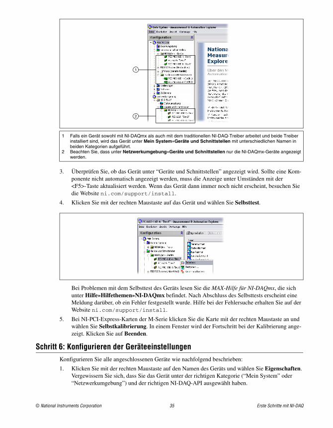
© National Instruments Corporation 35 Erste Schritte mit NI-DAQ
3. Überprüfen Sie, ob das Gerät unter “Geräte und Schnittstellen” angezeigt wird. Sollte eine Kom-ponente nicht automatisch angezeigt werden, muss die Anzeige unter Umständen mit der <F5>-Taste aktualisiert werden. Wenn das Gerät dann immer noch nicht erscheint, besuchen Sie die Website ni.com/support/install.
4. Klicken Sie mit der rechten Maustaste auf das Gerät und wählen Sie Selbsttest.
Bei Problemen mit dem Selbsttest des Geräts lesen Sie die MAX-Hilfe für NI-DAQmx, die sich unter Hilfe»Hilfethemen»NI-DAQmx befindet. Nach Abschluss des Selbsttests erscheint eine Meldung darüber, ob ein Fehler festgestellt wurde. Hilfe bei der Fehlersuche erhalten Sie auf der Website ni.com/support/install.
5. Bei NI-PCI-Express-Karten der M-Serie klicken Sie die Karte mit der rechten Maustaste an und wählen Sie Selbstkalibrierung. In einem Fenster wird der Fortschritt bei der Kalibrierung ange-zeigt. Klicken Sie auf Beenden.
Schritt 6: Konfigurieren der GeräteeinstellungenKonfigurieren Sie alle angeschlossenen Geräte wie nachfolgend beschrieben:
1. Klicken Sie mit der rechten Maustaste auf den Namen des Geräts und wählen Sie Eigenschaften. Vergewissern Sie sich, dass Sie das Gerät unter der richtigen Kategorie (“Mein System” oder “Netzwerkumgebung”) und der richtigen NI-DAQ-API ausgewählt haben.
1 Falls ein Gerät sowohl mit NI-DAQmx als auch mit dem traditionellen NI-DAQ-Treiber arbeitet und beide Treiber installiert sind, wird das Gerät unter Mein System»Geräte und Schnittstellen mit unterschiedlichen Namen in beiden Kategorien aufgeführt.
2 Beachten Sie, dass unter Netzwerkumgebung»Geräte und Schnittstellen nur die NI-DAQmx-Geräte angezeigt werden.
1
2
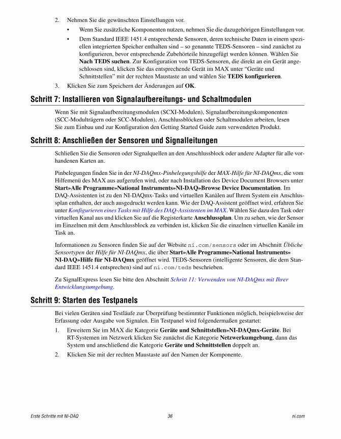
Erste Schritte mit NI-DAQ 36 ni.com
2. Nehmen Sie die gewünschten Einstellungen vor.
• Wenn Sie zusätzliche Komponenten nutzen, nehmen Sie die dazugehörigen Einstellungen vor.
• Dem Standard IEEE 1451.4 entsprechende Sensoren, deren technische Daten in einem spezi-ellen integrierten Speicher enthalten sind – so genannte TEDS-Sensoren – sind zunächst zu konfigurieren, bevor entsprechende Zubehörteile hinzugefügt werden können. Wählen Sie Nach TEDS suchen. Zur Konfiguration von TEDS-Sensoren, die direkt an ein Gerät ange-schlossen sind, klicken Sie das entsprechende Gerät im MAX unter “Geräte und Schnittstellen” mit der rechten Maustaste an und wählen Sie TEDS konfigurieren.
3. Klicken Sie zum Speichern der Änderungen auf OK.
Schritt 7: Installieren von Signalaufbereitungs- und SchaltmodulenWenn Sie mit Signalaufbereitungsmodulen (SCXI-Modulen), Signalaufbereitungskomponenten (SCC-Modulträgern oder SCC-Modulen), Anschlussblöcken oder Schaltmodulen arbeiten, lesenSie zum Einbau und zur Konfiguration den Getting Started Guide zum verwendeten Produkt.
Schritt 8: Anschließen der Sensoren und SignalleitungenSchließen Sie die Sensoren oder Signalquellen an den Anschlussblock oder andere Adapter für alle vor-handenen Karten an.
Pinbelegungen finden Sie in der NI-DAQmx-Pinbelegungshilfe der MAX-Hilfe für NI-DAQmx, die vom Hilfemenü des MAX aus aufgerufen wird, oder nach Installation des Device Document Browsers unter Start»Alle Programme»National Instruments»NI-DAQ»Browse Device Documentation. Im DAQ-Assistenten ist zu den NI-DAQmx-Tasks und virtuellen Kanälen auf Ihrem System ein Anschlus-splan enthalten, der auch ausgedruckt werden kann. Wie der DAQ-Assistent geöffnet wird, erfahren Sie unter Konfigurieren eines Tasks mit Hilfe des DAQ-Assistenten im MAX. Wählen Sie dazu den Task oder virtuellen Kanal aus und klicken Sie auf die Registerkarte Anschlussplan. Um zu sehen, wie der Sensor im Einzelnen mit dem Anschlussblock zu verbinden ist, klicken Sie die einzelnen virtuellen Kanäle im Task an.
Informationen zu Sensoren finden Sie auf der Website ni.com/sensors oder im Abschnitt Übliche Sensortypen der Hilfe für NI-DAQmx, die über Start»Alle Programme»National Instruments»NI-DAQ»Hilfe für NI-DAQmx geöffnet wird. TEDS-Sensoren (intelligente Sensoren, die dem Stan-dard IEEE 1451.4 entsprechen) sind auf ni.com/teds beschrieben.
Zu SignalExpress lesen Sie bitte den Abschnitt Schritt 11: Verwenden von NI-DAQmx mit Ihrer Entwicklungsumgebung.
Schritt 9: Starten des TestpanelsBei vielen Geräten sind Testläufe zur Überprüfung bestimmter Funktionen möglich, beispielsweise der Erfassung oder Ausgabe von Signalen. Ein Testpanel wird folgendermaßen gestartet:
1. Erweitern Sie im MAX die Kategorie Geräte und Schnittstellen»NI-DAQmx-Geräte. Bei RT-Systemen im Netzwerk klicken Sie zunächst die Kategorie Netzwerkumgebung, dann das System und anschließend die Kategorie Geräte und Schnittstellen doppelt an.
2. Klicken Sie mit der rechten Maustaste auf den Namen der Komponente.
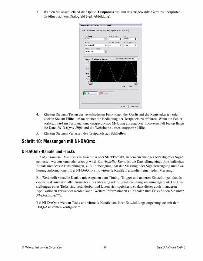
© National Instruments Corporation 37 Erste Schritte mit NI-DAQ
3. Wählen Sie anschließend die Option Testpanels aus, um das ausgewählte Gerät zu überprüfen. Es öffnet sich ein Dialogfeld (vgl. Abbildung).
4. Klicken Sie zum Testen der verschiedenen Funktionen des Geräts auf die Registerkarten oder klicken Sie auf Hilfe, um mehr über die Bedienung der Testpanels zu erfahren. Wenn ein Fehler vorliegt, wird im Testpanel eine entsprechende Meldung ausgegeben. In diesem Fall bieten Ihnen die Datei NI-DAQmx-Hilfe und die Website ni.com/support Hilfe.
5. Klicken Sie zum Verlassen des Testpanels auf Schließen.
Schritt 10: Messungen mit NI-DAQmx
NI-DAQmx-Kanäle und -Tasks Ein physikalischer Kanal ist ein Anschluss oder Steckkontakt, an dem ein analoges oder digitales Signal gemessen werden kann oder erzeugt wird. Ein virtueller Kanal ist die Darstellung eines physikalischen Kanals und dessen Einstellungen, z. B. Pinbelegung, Art der Messung oder Signalerzeugung und Ska-lierungsinformationen. Bei NI-DAQmx sind virtuelle Kanäle Bestandteil einer jeden Messung.
Ein Task stellt virtuelle Kanäle mit Angaben zum Timing, Trigger und anderen Einstellungen dar. In einem Task sind also alle Parameter einer Messung oder Signalerzeugung zusammengefasst. Die Ein-stellungen eines Tasks sind veränderbar und lassen sich speichern, so dass dieser auch in anderen Applikationen verwendet werden kann. Weitere Informationen zu Kanälen und Tasks finden Sie unter NI-DAQmx-Hilfe.
Bei NI-DAQmx werden Tasks und virtuelle Kanäle von Ihrer Entwicklungsumgebung aus mit dem DAQ-Assistenten konfiguriert.
Erste Schritte mit NI-DAQ 38 ni.com
Konfigurieren eines Tasks mit Hilfe des DAQ-Assistenten im MAXFühren Sie folgende Schritte aus, um mit dem DAQ-Assistenten im MAX einen Task zu erstellen:
1. Klicken Sie im MAX mit der rechten Maustaste auf Datenumgebung und wählen Sie Neu, um den DAQ-Assistenten zu öffnen.
2. Wählen Sie NI-DAQmx-Task und klicken Sie auf Weiter.
3. Wählen Sie entweder Signale erfassen oder Signale erzeugen.
4. Wählen Sie einen I/O-Typ (z. B. analoge Erfassung) und die Art der Messung aus (z. B. Spannung).
5. Wählen Sie die gewünschten physikalischen Kanäle aus und klicken Sie auf Weiter.
6. Geben Sie dem Task einen Namen und klicken Sie auf Beenden.
7. Nehmen Sie alle Einstellungen zu Ihren Kanälen vor. Dazu gehört zum Beispiel, jeden physikali-schen Kanal in einem Task einem virtuellen Kanal zuzuordnen. Um den Eingangswertebereich zu ändern oder andere Einstellungen vorzunehmen, markieren Sie den Kanal. Klicken Sie dann auf Details anzeigen. Nehmen Sie anschließend zum Beispiel Timing- und Trigger-Einstellungen zum Task vor. Klicken Sie auf Testen.
Schritt 11: Verwenden von NI-DAQmx mit Ihrer EntwicklungsumgebungDer DAQ-Assistent funktioniert auch mit LabVIEW, LabWindows/CVI und Measurement Studio ab Version 7.x sowie mit LabVIEW SignalExpress ab Version 2.x.
Auf den NI-DAQmx-CDs befindet sich auch LabVIEW SignalExpress LE, ein einfach zu nutzendes Programm, das speziell für Anwendungen zur Datenprotokollierung vorgesehen ist. Zum Öffnen des Programms wählen Sie Start»Alle Programme»National Instruments»LabVIEW SignalExpress. Die Hilfe zu LabVIEW SignalExpress befindet sich in LabVIEW SignalExpress unter Hilfe»Hilfethemen»LabVIEW SignalExpress Hilfe.
Zum Einstieg in Ihre Entwicklungsumgebung empfehlen wir folgende Anleitungen für Anfänger:
• Die LabVIEW-Anleitung zum Umgang mit dem DAQ-Assistenten (in LabVIEW unter Hilfe»Erste Schritte»Erste Schritte mit DAQ»Messungen mit NI-DAQmx in LabVIEW).
• Die LabWindows/CVI-Anleitung zum Umgang mit dem DAQ-Assistenten (in LabWindows/CVI unter Help»Help Topics»Taking an NI-DAQmx Measurement in LabWindows/CVI).
• Die Measurement-Studio-Anleitung zum DAQ-Assistenten (unter Measurement Studio»NI Measurement Studio Help»Getting Started with the Measurement Studio Class Libraries»Measurement Studio Walkthroughs»Walkthrough: Creating a Measurement Studio NI-DAQmx Application).
• Die LabVIEW-SignalExpress-Anleitung zum Umgang mit dem DAQ-Assistenten (in LabVIEW SignalExpress unter Hilfe»Erste Schritte»Erste Schritte mit»Taking an NI-DAQmx Measurement in LabVIEW SignalExpress).
© National Instruments Corporation 39 Erste Schritte mit NI-DAQ
BeispieleMit Beispielen können Sie eine neue Anwendung erstellen oder eine bestehende Anwendung erweitern.
Zusätzliche Beispiele sind unter ni.com/zone zu finden. Mit der NI-DAQmx-Simulationsfunktion lassen sich Beispiele auch ausführen, ohne dass die benötigten Geräte angeschlossen sind. Wie ein Gerät simuliert wird, ist in der Hilfe zum Measurement & Automation Explorer für NI-DAQmx nachzulesen, die im MAX über Hilfe»Hilfethemen»NI-DAQmx geöffnet wird.
Weitere InformationenNach der Installation der Dokumentation lässt sich diese über Start»Alle Programme»National Instruments»NI-DAQ»Browse Device Documentation aufrufen. Die Beschreibungen zu NI-DAQ, wie die Hilfe für NI-DAQmx oder die vorliegende Anleitung Erste Schritte mit NI-DAQ (als PDF-Datei), können über Start»Alle Programme»National Instruments»NI-DAQ»NI-DAQmx Titel des Doku-ments geöffnet werden.
Die Gerätebeschreibungen können auch durch einen Rechtsklick auf ein Gerät im MAX und Auswahl der Option Hilfe»Online-Gerätedokumentation geöffnet werden. Daraufhin wird die Seite ni.com/manuals mit den gefundenen Dokumenten geöffnet. Auf ni.com/manuals finden Sie auch Beschreibungen zu neuen Geräten, die seit dem letzten Release von NI-DAQmx auf den Markt gekom-men sind, sowie neuere Ausgaben von Beschreibungen, die im Device Document Browser auf Ihrer CD noch nicht enthalten sind.
Anwendung Speicherort (Beispiel)
LabVIEW oder LabWindows/CVI Hilfe»Beispiele suchen
LabVIEW SignalExpress Programme\National Instruments\SignalExpress\Examples
ANSI C NI-DAQ\Examples\DAQmx ANSI C
Von Measurement Studio unterstützte Programmiersprachen
MFC 7.0 C++ NI-DAQ\Examples\MStudioVC2003
Beispiele zu Visual Basic .NET und C# für Visual Studio 2003* NI-DAQ\Examples\DotNET1.1
MFC 8.0 C++ NI-DAQ\Examples\MStudioVC2005
Beispiele zu Visual Basic .NET und C# für Visual Studio 2005* NI-DAQ\Examples\DotNET2.0
* Measurement Studio nicht erforderlich
National Instruments, NI, ni.com und LabVIEW sind Marken der Firma National Instruments Corporation. Nähere Informationen zu den Marken von National Instruments finden Sie im Abschnitt Terms of Use unter ni.com/legal. Sonstige hierin erwähnte Produkt- und Firmenbezeichnungen sind Marken oder Handelsnamen der jeweiligen Unternehmen. Nähere Informationen über Patente auf Produkte von National Instruments finden Sie unter Hilfe»Patente in Ihrer Software, in der Datei patents.txt auf Ihrer CD oder unter ni.com/patents.
© 2003–2007 National Instruments Corporation. Alle Rechte vorbehalten. 373235M Jun07
FehlersucheNachfolgend sind einige Informationsquellen aufgeführt, die Ihnen bei Problemen mit der Installation Ihrer Hard- oder Software zur Datenerfassung von Nutzen sein können:
• Bei Problemen besuchen Sie bitte unsere Website ni.com/support/install und gehen Sie nach den Anweisungen im “Hardware Installation/Configuration Troubleshooter” vor.
• Auf ni.com/kb finden Sie häufig gestellte Fragen und Hilfe zu Problemen bei der Installation oder Programmierung.
• Falls Sie ein Gerät aufgrund einer Beschädigung zur Reparatur oder Kalibrierung an National Instruments zurücksenden müssen, besuchen Sie die Website ni.com/support und geben Sie die Buchstabenkombination rdsenn ein. Hier erfahren Sie, was bei der Warenrücksendung an National Instruments zu beachten ist.
Weltweite technische UnterstützungWeitere Unterstützung finden Sie auf der Website ni.com/support oder ni.com/zone. Informa-tionen zu Signalaufbereitungsgeräten finden Sie im Dokument Signal Conditioning Technical Support Information in der Packungsbeilage des Geräts.
Bei Anfragen wenden Sie sich bitte an eine Niederlassung von National Instruments. Die Adresse der Hauptgeschäftsstelle von National Instruments in den USA lautet: 11500 North Mopac Expressway, Austin, Texas, 78759-3504.
DAQ スタートアップガイド
このドキュメントは、Windows 用 NI-DAQmx ドライバソフトウェアおよびデータ集録(DAQ)デバイスのインストール、構成、およびデバイスの動作確認の方法について説明します。 Linux 環境でのインストール手順については、ni.com/downloadsから入手できる
『NI-DAQmx for Linux Readme 』を参照してください。 従来の NI-DAQ(レガシー)の構成方法については、『従来型 NI-DAQ(レガシー)Readme』を参照してください。この
Readme は、ソフトウェアのインストール後にスタート→プログラム→ National Instruments → NI-DAQ を選択して表示できます。
NI-DAQ ソフトウェア
ナショナルインスツルメンツの M シリーズマルチファンクション I/O(MIO)DAQ デバイスなどの計測デバイスには、NI LabVIEW、NI LabWindows™/CVI™、Microsoft Visual Studio .NET、NI LabVIEW SignalExpress などのアプリケーションソフトウェアから NI デバイスのプログラムから呼び出し可能な VI、ANSI C 関数、.NET 関数の豊富なライブラリである NI-DAQ ドライバソフトウェアが添付されています。 ドライバソフトウェアにはさらに、デバイスのアプリケーション作成に使用できる VI、関数、クラス、属性、プロパティのライブラリであるアプリケーションプログラミングインタフェース(API)が含まれています。
NI-DAQ 7.x 以降では、異なる API と構成を持つ 2 種類の NI-DAQ ドライバが用意されています。 NI-DAQmx は最新の NI-DAQ ドライバで、従来型 NI-DAQ(レガシー)よりも優れています。
• DAQ アシスタント―デバイスの仮想チャンネルおよび計測タスクを作成し、
LabVIEW、LabWindows/CVI、Measurement Studio、VI Logger、LabVIEW SignalExpress、Measurement & Automation Explorer(MAX)で使用できる
NI-DAQmx コードを生成するためのグラフィカルツール。
• 高速なシングルポイントアナログ I/O やマルチスレッドを始めとするパフォーマンスの向上。
• ハードウェアを接続することなく実行できる、サポート対象デバイスのテストやアプリケーション変更の NI-DAQmx シミュレーション。NI-DAQmx でサポートされていても
NI-DAQmx でのシミュレーション機能を持たないデバイスもあります。それらのデバイスの一覧は『NI-DAQ Readme』に記載されています。
• シンプルで直感的な API を使用して、旧バージョンより少ない関数と VI で DAQ アプリケーションを完成。
従来型 NI-DAQ(レガシー)は、ナショナルインスツルメンツの古い DAQ デバイスのデータ集録、計測、制御のアプリケーションを開発する旧版の API とともに使用する古いドライバです。 したがって、従来型 NI-DAQ(レガシー)は特定の環境においてのみ使用してください。 従来型 NI-DAQ(レガシー)を使用しなければならない特定の条件(サポートされるデバイス、オペレーティングシステム、アプリケーションソフトウェア、多言語バージョンの一覧など)については、『NI-DAQ Readme』を参照してください。 従来型 NI-DAQ
(レガシー)は、ni.com/downloadsからダウンロードできます。
DAQ スタートアップガイド 42 ni.com/jp
手順 1. ソフトウェアをインストールする
NI アプリケーションソフトウェアをインストールします。 NI-DAQmx は、LabVIEW、
LabWindows/CVI、Measurement Studio versions 7.x 以降、LabVIEW SignalExpress 2.x 以降、LabVIEW Real-Time Module 7.1 以降でサポートされています。 旧バージョンのアプリケーション開発環境または NI-DAQ で作成されたアプリケーションを使用している場合は、そのアプリケーションのバックアップコピーを作成します。 これにより、ソフトウェアをアップグレードした後に、アプリケーションを修正することができます。
手順 2. NI-DAQ をインストールする
Windows によってデバイスが自動検出されるように、新規ハードウェアデバイスをインストールする前にドライバソフトウェアをインストールします。 既存のアプリケーションに、サポートされていないコンポーネント(『NI-DAQ Readme』の一覧を参照)が含まれている場合は、NI-DAQ をインストールしてはなりません。
注意 NI-DAQ 7.x 以降のバージョンは、NI-DAQ 7.0 より前のバージョンと同じシステムにインストールできません。
1. CD 1 をコンピュータに挿入します。NI-DAQ のインストーラが自動的に起動します。 インストーラが起動しない場合は、スタート→ファイル名を指定して実行を選択してください。 x:¥autorun.exeと入力します。ここで、xは CD ドライブの文字を示します。 トラブルシューティングの説明については、ni.com/support/ja/troubleshootingのトラブルシューティングリソースを参照してください。
2. ソフトウェアをインストールします。
• ソフトウェアをインストールをクリックすると、ソフトウェアおよび / またはドキュメントファイルがハードディスクにコピーされます。 NI-DAQ ソフトウェアのドキュメントは、ドライバソフトウェアと同時にインストールされます。
• Readme ファイルを表示を選択すると Readme ファイルが開きます。
• CD を参照をクリックすると、ドキュメントをインストールせずに CD から表示、検索、印刷できます。
NI-DAQ インストーラはシステムにインストールされている NI ソフトウェアを検出し、最新のドライバ、アプリケーションソフトウェア、および言語サポートファイルを CDから自動的にインストールします。 インストーラによって正しいサポートファイルとバージョンが検出され、選択されていることを確認してください。 NI-DAQ をインストールした後に、他の NI アプリケーションソフトウェアをインストールする場合は、
NI-DAQ インストーラを再度実行して適切なアプリケーションソフトウェアサポートファイルをインストールする必要があります。
3. 画面の指示に従います。 Windows Vista 環境では、アクセス / セキュリティメッセージが表示される場合があります。 画面の指示に従って、インストールを完了します。
4. NI-DAQ インストーラの処理が完了すると、ダイアログボックスがいくつか表示されます。 次へをクリックしてインストールを完了します。
© National Instruments Corporation 43 DAQ スタートアップガイド
5. 最後のダイアログボックスには、以下のオプションが表示されます。
• 他の NI ソフトウェアまたはドキュメントをインストールするには、後で再起動を選択します。
– サポートされているデバイスおよびアクセサリのオンラインドキュメント(デバイスの端子、仕様、機能、および操作を説明した PDF およびヘルプファイル等)をインストールできます。 デバイスのドキュメント CD 2 をコンピュータにセットしてインストーラ画面を表示します。 Install Device Documentation を選択します。
– PC から PXI シャーシを制御するために MXI-3 を使用している場合は、DAQデバイスを使用する前に終了し、ni.com/jp/downloadsから入手できる
MXI-3 ソフトウェアをインストールしてください。
• デバイスをインストールする準備ができたら、シャットダウンまたは再起動を選択します。
• LabVIEW Real-Time モジュールを実行しているシステムを使用している場合は、再起動を選択します。 MAX を使用して NI-DAQ をターゲットへダウンロードします。手順については『Measurement & Automation Explorer リモートシステムヘルプ』を参照してください。これは、MAX でヘルプ→ヘルプトピック→リモートシステムを選択して開くことができます。
手順 3. デバイス、アクセサリ、およびケーブルを箱から取り出す
デバイスを箱から取り出し、部品がゆるんでいないかどうか、また、破損箇所がないかどうか調べます。 デバイスが損傷している場合は、ナショナルインスツルメンツまでご連絡ください。 損傷したデバイスは使用しないでください。
安全およびコンプライアンスに関する情報は、各デバイスのマニュアルに記載されています。これらのマニュアルは ni.com/manualsからダウンロードするか、製品をインストール済みの場合はスタート→すべてのプログラム→ National Instruments → NI-DAQ →
Browse Device Documentation を選択して表示できます。
デバイスでは、たとえば次のような記号が使用されていることがあります。
このアイコンは、負傷、データの損失、システムの破壊を防止するための注意事項を示します。 デバイスにこの記号が付いている場合は、添付されている『Read Me First: Safety and Radio-Frequency Interference』というドキュメントを参照して必要な安全対策を講じてください。
この記号は、電気ショックを防止するための事前対策についての警告を示します。
この記号は、熱を帯びる可能性があるコンポーネントを示します。 このコンポーネントに接触すると、負傷するおそれがあります。
手順 4. デバイス、アクセサリ、ケーブルを取り付ける
複数の DAQ デバイスを取り付ける場合は、下記のデバイスタイプ別の手順に従ってこの段階ですべて取り付けます。 DAQ デバイスに SCXI モジュールを接続する場合は、まず DAQコンポーネントを取り付けます。
注意 ハードウェアの取り付け作業は、静電破壊防止方法に従って身体に適切な接地対策を施してから行ってください。 安全とコンプライアンスに関する情報については、デバイスの仕様書を参照してください。
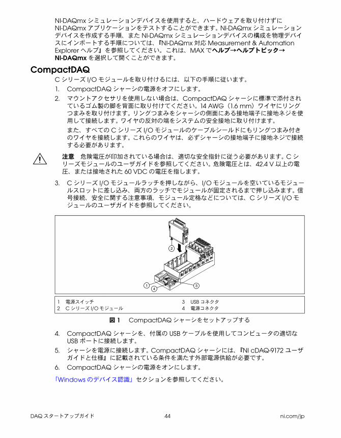
DAQ スタートアップガイド 44 ni.com/jp
NI-DAQmx シミュレーションデバイスを使用すると、ハードウェアを取り付けずに
NI-DAQmx アプリケーションをテストすることができます。 NI-DAQmx シミュレーションデバイスを作成する手順、また NI-DAQmx シミュレーションデバイスの構成を物理デバイスにインポートする手順については、『NI-DAQmx 対応 Measurement & Automation Explorer ヘルプ』を参照してください。これは、MAX でヘルプ→ヘルプトピック→
NI-DAQmx を選択して開くことができます。
CompactDAQC シリーズ I/O モジュールを取り付けるには、以下の手順に従います。
1. CompactDAQ シャーシの電源をオフにします。
2. マウントアクセサリを使用しない場合は、CompactDAQ シャーシに標準で添付されているゴム製の脚を背面に取り付けてください。 14 AWG(1.6 mm)ワイヤにリングつまみを取り付けます。 リングつまみをシャーシの側面にある接地端子に接地ネジを使用して接続します。 ワイヤの反対の端をシステムの安全接地に取り付けます。
また、すべての C シリーズ I/O モジュールのケーブルシールドにもリングつまみ付きのワイヤを接続します。 これらのワイヤは、必ずシャーシの接地端子に接地ネジで接続する必要があります。
注意 危険電圧が印加されている場合は、適切な安全指針に従う必要があります。 C シリーズモジュールのユーザガイドを参照してください。 危険電圧とは、42.4 V 以上の電圧、または接地された 60 VDC の電圧を指します。
3. C シリーズ I/O モジュールラッチを押しながら、I/O モジュールを空いているモジュールスロットに差し込み、両方のラッチでモジュールが固定されるまで押し込みます。 信号接続、安全に関する注意事項、モジュール定格などについては、C シリーズ I/O モジュールのユーザガイドを参照してください。
.
図 1 CompactDAQ シャーシをセットアップする
4. CompactDAQ シャーシを、付属の USB ケーブルを使用してコンピュータの適切な
USB ポートに接続します。
5. シャーシを電源に接続します。 CompactDAQ シャーシには、『NI cDAQ-9172 ユーザガイドと仕様』に記載されている条件を満たす外部電源供給が必要です。
6. CompactDAQ シャーシの電源をオンにします。
「Windows のデバイス認識」セクションを参照してください。
1 電源スイッチ 2 C シリーズ I/O モジュール
3 USB コネクタ
4 電源コネクタ
NI cDAQ-9051
Ready
Active
11-30 VDC
2 A Max
OFF
ON
431
2
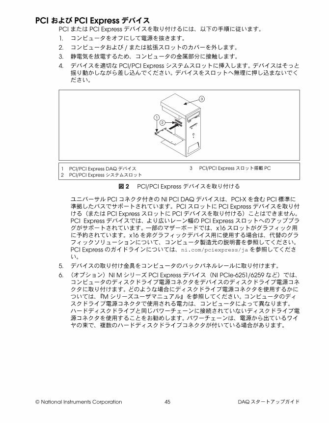
© National Instruments Corporation 45 DAQ スタートアップガイド
PCI および PCI Express デバイスPCI または PCI Express デバイスを取り付けるには、以下の手順に従います。
1. コンピュータをオフにして電源を抜きます。
2. コンピュータおよび / または拡張スロットのカバーを外します。
3. 静電気を放電するため、コンピュータの金属部分に接触します。
4. デバイスを適切な PCI/PCI Express システムスロットに挿入します。 デバイスはそっと揺り動かしながら差し込んでください。 デバイスをスロットへ無理に押し込まないでください。
図 2 PCI/PCI Express デバイスを取り付ける
ユニバーサル PCI コネクタ付きの NI PCI DAQ デバイスは、PCI-X を含む PCI 標準に準拠したバスでサポートされています。PCI スロットに PCI Express デバイスを取り付ける(または PCI Express スロットに PCI デバイスを取り付ける)ことはできません。 PCI Express デバイスでは、より広いレーン幅の PCI Express スロットへのアッププラグがサポートされています。 一部のマザーボードでは、x16 スロットがグラフィック用に予約されています。x16 を非グラフィックデバイス用に使用する場合は、代替のグラフィックソリューションについて、コンピュータ製造元の説明書を参照してください。 PCI Express のガイドラインについては、ni.com/pciexpress/jaを参照してください。
5. デバイスの取り付け金具をコンピュータのバックパネルレールに取り付けます。
6. (オプション)NI M シリーズ PCI Express デバイス(NI PCIe-6251/6259 など)では、コンピュータのディスクドライブ電源コネクタをデバイスのディスクドライブ電源コネクタに取り付けます。 どのような場合にディスクドライブ電源コネクタを使用するかについては、『M シリーズユーザマニュアル』を参照してください。 コンピュータのディスクドライブ電源コネクタで使用される電力は、コンピュータによって異なります。 ハードディスクドライブと同じパワーチェーンに接続されていないディスクドライブ電源コネクタを使用することをお勧めします。 パワーチェーンは、電源から出ているワイヤの束で、複数のハードディスクドライブコネクタが付いている場合があります。
1 PCI/PCI Express DAQ デバイス
2 PCI/PCI Express システムスロット
3 PCI/PCI Express スロット搭載 PC
3
12
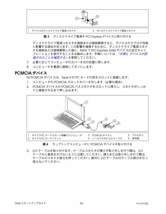
DAQ スタートアップガイド 46 ni.com/jp
図 3 ディスクドライブ電源を PCI Express デバイスに取り付ける
ディスクドライブ電源コネクタを接続または接続解除すると、デバイスのアナログ性能に影響する場合があります。 この影響を補償するために、ディスクドライブ電源コネクタを接続または接続解除した後に、MAX で PCI Express DAQ デバイスの自己キャリブレーションを実行することをお勧めします。 手順については、「手順 5. デバイスが認識されたことを確認する」を参照してください。
7. 必要に応じてコンピュータのカバーを元の位置に戻します。
8. コンピュータを電源に接続してオンにします。
PCMCIA デバイスNI PCMCIA デバイスは、Type II の PC カードの空きスロットに設置します。
1. コンピュータの PCMCIA スロットカバーを外します(必要な場合)。
2. PCMCIA デバイスの PCMCIA バスコネクタをスロットに挿入し、コネクタがしっかりと接続されるまで押し込みます。
図 4 ラップトップコンピュータに PCMCIA デバイスを取り付ける
3. I/O ケーブルを取り付けます。 ケーブルコネクタの挿入や取り外しを行う際は、I/Oケーブルに負担をかけないように注意してください。 挿入または取り外しを行う際は、ケーブルのコネクタ部分を持ってください。 絶対に I/O ケーブルのケーブル部分を引っ張らないでください。
1 デバイスのディスクドライブ電源コネクタ 2 PC のディスクドライブ電源コネクタ
1 タイプ II PC カードスロット搭載のコンピュータ
2 タイプ II PC カードソケット
3 PCMCIA デバイス
4 シールドされた I/O ケーブル
5 アクセサリ
6 信号線
12
®
®
DAQCard
1
2
34
56
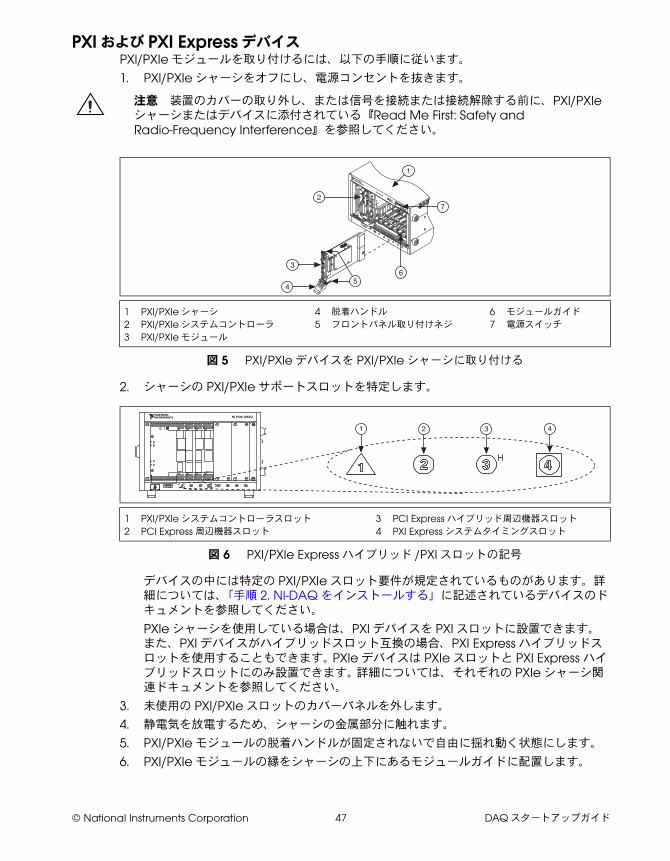
© National Instruments Corporation 47 DAQ スタートアップガイド
PXI および PXI Express デバイスPXI/PXIe モジュールを取り付けるには、以下の手順に従います。
1. PXI/PXIe シャーシをオフにし、電源コンセントを抜きます。
注意 装置のカバーの取り外し、または信号を接続または接続解除する前に、PXI/PXIeシャーシまたはデバイスに添付されている『Read Me First: Safety and Radio-Frequency Interference』を参照してください。
図 5 PXI/PXIe デバイスを PXI/PXIe シャーシに取り付ける
2. シャーシの PXI/PXIe サポートスロットを特定します。
図 6 PXI/PXIe Express ハイブリッド /PXI スロットの記号
デバイスの中には特定の PXI/PXIe スロット要件が規定されているものがあります。詳細については、「手順 2. NI-DAQ をインストールする」に記述されているデバイスのドキュメントを参照してください。
PXIe シャーシを使用している場合は、PXI デバイスを PXI スロットに設置できます。また、PXI デバイスがハイブリッドスロット互換の場合、PXI Express ハイブリッドスロットを使用することもできます。 PXIe デバイスは PXIe スロットと PXI Express ハイブリッドスロットにのみ設置できます。 詳細については、それぞれの PXIe シャーシ関連ドキュメントを参照してください。
3. 未使用の PXI/PXIe スロットのカバーパネルを外します。
4. 静電気を放電するため、シャーシの金属部分に触れます。
5. PXI/PXIe モジュールの脱着ハンドルが固定されないで自由に揺れ動く状態にします。
6. PXI/PXIe モジュールの縁をシャーシの上下にあるモジュールガイドに配置します。
1 PXI/PXIe シャーシ
2 PXI/PXIe システムコントローラ
3 PXI/PXIe モジュール
4 脱着ハンドル
5 フロントパネル取り付けネジ
6 モジュールガイド
7 電源スイッチ
1 PXI/PXIe システムコントローラスロット
2 PCI Express 周辺機器スロット
3 PCI Express ハイブリッド周辺機器スロット
4 PXI Express システムタイミングスロット
3
2
4
PXI-1000B
7
56
1
NI PXIe-1062Q
1 2 3 4
DAQ スタートアップガイド 48 ni.com/jp
7. デバイスを PXI/PXIeI スロットに差し込み、シャーシ背面に向かってスライドさせます。
8. 抵抗を感じたら、脱着ハンドルを引き上げてデバイスを固定します。
9. シャーシのフロントパネル取り付けレールに、デバイスのフロントパネルをネジで取り付けます。
10. PXI/PXIe シャーシを電源に接続してオンにします。
USB デバイスUSB 対応の NI デバイスを取り付けるには、以下の手順に従います。
1. 電源を接続します。
• BP-1 バッテリーパックを使用している場合は、BP-1 の取り付け手順書に従います。
• USB 対応の NI デバイスの中には外部電源が必要なデバイスもあります。 デバイスが外部電源を使用するタイプの場合、外部電源(ある場合)の電圧が、デバイスを使用する地域の電圧(120/230 VAC)とデバイスが必要とする電圧に合っているか確認してください。
2. 電源コードの一方をコンセントに接続し、もう一方をデバイスに接続します。
3. コンピュータの USB ポートまたはその他のハブから、デバイスの使用可能な USB ポートへケーブルを接続します。
4. USB デバイスに電源スイッチがある場合、デバイスの電源を入れます。 コンピュータがデバイスを即座に検出します。
コンピュータが USB を認識すると、デバイスの LED が点滅または点灯します。 LED の点滅パターンおよびトラブルシューティングについては、各デバイスのマニュアルを参照してください。
Windows のデバイス認識ハードウェアのインストール後に初めてコンピュータを起動すると、Windows によって新しくインストールされたデバイスが認識されます。 一部の Windows システムでは、インストールされたすべての NI デバイスに対して、新しいハードウェアの検索ウィザードが起動します。 デフォルトでは、デバイスに最適なドライバを検索する(推奨)が選択されています。 次へまたははいをクリックして、各デバイスのソフトウェアをインストールします。
Windows が新しくインストールされた NI USB デバイス(CompactDAQ デバイスを含む)を認識すると、以下のオプションを選択するためのダイアログボックスが表示されます。表示されるオプションは、システムにインストールされているデバイスとソフトウェアによって異なります。
• LabVIEW で測定を開始するを選択すると、LabVIEW が起動します。
• NI LabVIEW SignalExpress を使用してこのデバイスの測定を開始するを選択すると、そのデバイスのチャンネルを LabVIEW SignalExpress で使用する DAQ ステップが開きます。 CompactDAQ シャーシを取り付けた場合は、使用するモジュールを選択するダイアログボックスにが表示されます。 アクセサリ、SCXI、センサを取り付けて構成する場合は、以下の「アクセサリ」のセクションと、「手順 5. デバイスが認識されたことを確認する」から「手順 9. テストパネルを実行する」までのセクションを参照してください。 それ以外の場合は、MAX で何も構成する必要はありません。LabVIEW SignalExpress での DAQ 計測の詳細については、「手順 11. アプリケーションソフトウェアで NI-DAQmx を使用する」を参照してください。
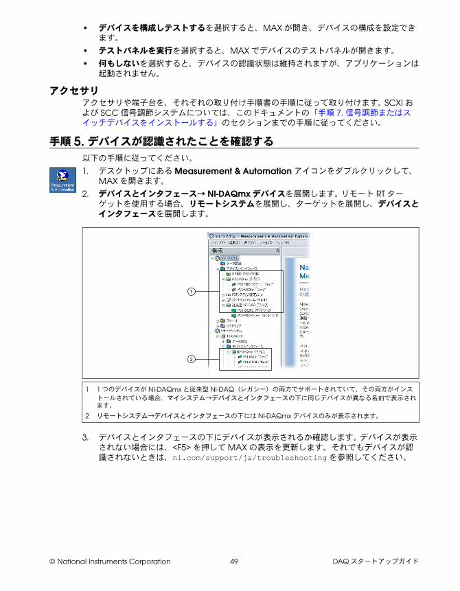
© National Instruments Corporation 49 DAQ スタートアップガイド
• デバイスを構成しテストするを選択すると、MAX が開き、デバイスの構成を設定できます。
• テストパネルを実行を選択すると、MAX でデバイスのテストパネルが開きます。
• 何もしないを選択すると、デバイスの認識状態は維持されますが、アプリケーションは起動されません。
アクセサリアクセサリや端子台を、それぞれの取り付け手順書の手順に従って取り付けます。 SCXI および SCC 信号調節システムについては、このドキュメントの「手順 7. 信号調節またはスイッチデバイスをインストールする」のセクションまでの手順に従ってください。
手順 5. デバイスが認識されたことを確認する
以下の手順に従ってください。
1. デスクトップにある Measurement & Automation アイコンをダブルクリックして、
MAX を開きます。
2. デバイスとインタフェース→ NI-DAQmx デバイスを展開します。 リモート RT ターゲットを使用する場合、リモートシステムを展開し、ターゲットを展開し、デバイスとインタフェースを展開します。
3. デバイスとインタフェースの下にデバイスが表示されるか確認します。 デバイスが表示されない場合には、<F5> を押して MAX の表示を更新します。それでもデバイスが認識されないときは、ni.com/support/ja/troubleshootingを参照してください。
1 1 つのデバイスが NI-DAQmx と従来型 NI-DAQ(レガシー)の両方でサポートされていて、その両方がインス
トールされている場合、マイシステム→デバイスとインタフェースの下に同じデバイスが異なる名前で表示されます。
2 リモートシステム→デバイスとインタフェースの下には NI-DAQmx デバイスのみが表示されます。
1
2
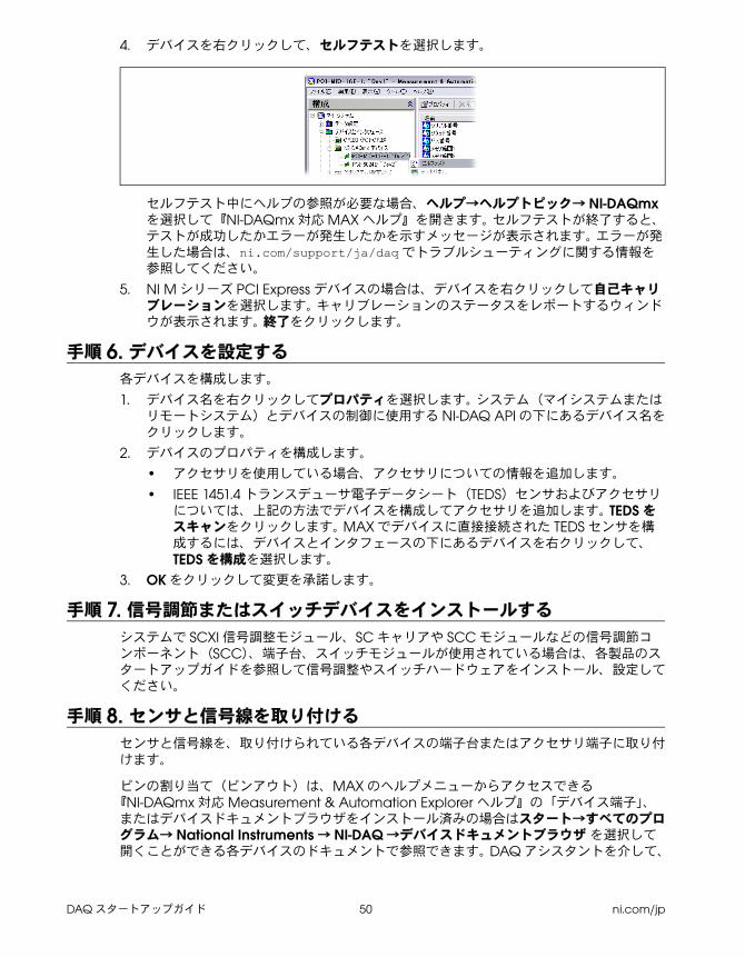
DAQ スタートアップガイド 50 ni.com/jp
4. デバイスを右クリックして、セルフテストを選択します。
セルフテスト中にヘルプの参照が必要な場合、ヘルプ→ヘルプトピック→ NI-DAQmxを選択して『NI-DAQmx 対応 MAX ヘルプ』を開きます。 セルフテストが終了すると、テストが成功したかエラーが発生したかを示すメッセージが表示されます。 エラーが発生した場合は、ni.com/support/ja/daqでトラブルシューティングに関する情報を参照してください。
5. NI M シリーズ PCI Express デバイスの場合は、デバイスを右クリックして自己キャリブレーションを選択します。 キャリブレーションのステータスをレポートするウィンドウが表示されます。 終了をクリックします。
手順 6. デバイスを設定する
各デバイスを構成します。
1. デバイス名を右クリックしてプロパティを選択します。 システム(マイシステムまたはリモートシステム)とデバイスの制御に使用する NI-DAQ API の下にあるデバイス名をクリックします。
2. デバイスのプロパティを構成します。
• アクセサリを使用している場合、アクセサリについての情報を追加します。
• IEEE 1451.4 トランスデューサ電子データシート(TEDS)センサおよびアクセサリについては、上記の方法でデバイスを構成してアクセサリを追加します。 TEDS をスキャンをクリックします。 MAX でデバイスに直接接続された TEDS センサを構成するには、デバイスとインタフェースの下にあるデバイスを右クリックして、
TEDS を構成を選択します。
3. OK をクリックして変更を承諾します。
手順 7. 信号調節またはスイッチデバイスをインストールする
システムで SCXI 信号調整モジュール、SC キャリアや SCC モジュールなどの信号調節コンポーネント(SCC)、端子台、スイッチモジュールが使用されている場合は、各製品のスタートアップガイドを参照して信号調整やスイッチハードウェアをインストール、設定してください。
手順 8. センサと信号線を取り付ける
センサと信号線を、取り付けられている各デバイスの端子台またはアクセサリ端子に取り付けます。
ピンの割り当て(ピンアウト)は、MAX のヘルプメニューからアクセスできる『NI-DAQmx 対応 Measurement & Automation Explorer ヘルプ』の「デバイス端子」、またはデバイスドキュメントブラウザをインストール済みの場合はスタート→すべてのプログラム→ National Instruments → NI-DAQ →デバイスドキュメントブラウザ を選択して開くことができる各デバイスのドキュメントで参照できます。 DAQ アシスタントを介して、
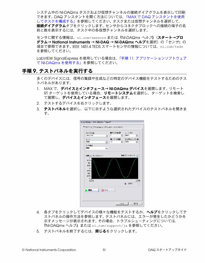
© National Instruments Corporation 51 DAQ スタートアップガイド
システム中の NI-DAQmx タスクおよび仮想チャンネルの接続ダイアグラムを表示して印刷できます。 DAQ アシスタントを開く方法については、「MAX で DAQ アシスタントを使用してタスクを構成する」を参照してください。 タスクまたは仮想チャンネルを選択して、接続ダイアグラムタブをクリックします。 センサからコネクタブロックへの接続の端子の名前と数を表示するには、タスク中の各仮想チャンネルを選択します。
センサに関する情報は、ni.com/sensorsまたは『NI-DAQmx ヘルプ』(スタート→プログラム→ National Instruments → NI-DAQ → NI-DAQmx ヘルプを選択)の「センサ」の項目で参照できます。 IEEE 1451.4 TEDS スマートセンサの情報については、ni.com/tedsを参照してください。
LabVIEW SignalExpress を使用している場合は、「手順 11. アプリケーションソフトウェアで NI-DAQmx を使用する」を参照してください。
手順 9. テストパネルを実行する
多くのデバイスには、信号の集録や生成などの特定のデバイス機能をテストするためのテストパネルがあります。
1. MAX で、デバイスとインタフェース→ NI-DAQmx デバイスを展開します。 リモート
RT ターゲットを使用している場合、リモートシステムを選択し、ターゲットを検索して展開し、デバイスとインタフェースを展開します。
2. テストするデバイスを右クリックします。
3. テストパネルを選択し、以下に示すような選択されたデバイスのテストパネルを開きます。
4. 各タブをクリックしてデバイスの様々な機能をテストするか、ヘルプをクリックしてテストパネルの操作方法を参照します。 テストパネルには、エラーが発生したかどうかを示すメッセージが表示されます。 その場合、トラブルシューティングについては、
『NI-DAQmx ヘルプ』または ni.com/support/jaを参照してください。
5. テストパネルを終了するには、閉じるをクリックします。
DAQ スタートアップガイド 52 ni.com/jp
手順 10. NI-DAQmx 計測を実行する
NI-DAQmx のチャンネルとタスク 「物理チャンネル」とは、アナログ / デジタル信号を計測または生成できる端子またはピンのことです。 これに対し、「仮想チャンネル」は、名前を物理チャンネルをその設定(入力端子接続、計測または生成のタイプ、およびスケール情報など)をマッピングするものです。 NI-DAQmx では、仮想チャンネルはすべての計測に不可欠です。
「タスク」は、タイミング、トリガ、その他のプロパティを備えた単一または複数の仮想チャンネルです。 タスクは、実行するべき計測または生成を表します。 タスクで構成情報を設定、保存し、それをアプリケーションで使用することができます。 チャンネルとタスクの詳細については、『NI-DAQmx ヘルプ』を参照してください。
NI-DAQmx では、MAX またはアプリケーションソフトウェア内で DAQ アシスタントを起動して仮想チャンネルとタスクを構成することができます。
MAX で DAQ アシスタントを使用してタスクを構成するMAX で DAQ アシスタントを起動してタスクを作成するには、以下の手順に従ってください。
1. DAQ アシスタントを起動するには、MAX でデータ設定を右クリックして、ショートカットメニューから新規作成を選択します。
2. 新規作成ウィンドウで NI-DAQmx タスクを選択して、次へをクリックします。
3. 信号を集録または信号を生成を選択します。
4. I/O タイプ(アナログ入力など)と、測定のタイプ(電圧など)を選択します。
5. 使用する物理チャンネルを選択して次へをクリックします。
6. タスク名を入力して終了をクリックします。
7. 個々のチャンネルを設定します。 タスクに割り当てる各物理チャンネルは、仮想チャンネル名を受け取ります。 入力範囲などの設定を変更するには、チャンネルを選択します。 物理チャンネルの情報を表示するには、詳細を表示をクリックします。 タスクのタイミングとトリガを構成します。 テストをクリックします。
手順 11. アプリケーションソフトウェアで NI-DAQmx を使用する
DAQ アシスタントは、LabVIEW、LabWindows/CVI、Measurement Studio のバージョン 7.x 以降、また LabVIEW SignalExpress の 2.x 以降で使用できます。
NI-DAQmx の CD には、データロギングアプリケーション専用の使いやすい構成ベースツールである LabVIEW SignalExpress LE が含まれています。 このツールは、スタート→すべてのプログラム→ National Instruments → LabVIEW SignalExpress を選択して起動できます。 『LabVIEW SignalExpress ヘルプ』を参照するには、LabVIEW SignalExpressでヘルプ→ヘルプトピック→ LabVIEW SignalExpress を選択します。
アプリケーションソフトウェアでの手順についてはチュートリアルを参照してください。
• LabVIEW DAQ アシスタントチュートリアルは、『LabVIEW ヘルプ』でスタートアップ→ DAQ 入門→ LabVIEW での NI-DAQmx 計測を選択して開くことができます。
• LabWindows/CVI DAQ Assistant チュートリアルは、LabWindows/CVI で Help →
Help Topics → Taking an NI-DAQmx Measurement in LabWindows/CVI を選択して開くことができます。
© National Instruments Corporation 53 DAQ スタートアップガイド
• Measurement Studio DAQ Assistant チュートリアルは、Measurement Studio →
NI Measurement Studio Help → Getting Started with the Measurement Studio Class Libraries → Measurement Studio Walkthroughs → Walkthrough: Creating a Measurement Studio NI-DAQmx Application を選択して開くことができます。
• LabVIEW SignalExpress DAQ アシスタントチュートリアルは、LabVIEW SignalExpress でヘルプ→スタートアップガイド→ LabVIEW SignalExpress での
NI-DAQmx 計測を選択して開くことができます。
サンプルサンプルを使用して、新しいアプリケーションを開発したり、サンプルのコードを既存のアプリケーションに加えたりすることができます。
その他のサンプルについては、ni.com/zone(英語)を参照してください。 ハードウェアを取り付けずにサンプルを実行するには、NI-DAQmx シミュレーションデバイスを使用します。 シミュレーションデバイスの作成手順については、MAX でヘルプ→ヘルプトピック→
NI-DAQmx を選択して、『NI-DAQmx 対応 Measurement & Automation Explorer ヘルプ』を参照してください。
その他の情報
デバイスドキュメントをインストールすると、ブラウザおよびドキュメントをスタート→プログラム→ National Instruments → NI-DAQ → Browse Device Documentation から表示できるようになります。 NI-DAQ ソフトウェアのドキュメント(『NI-DAQmx ヘルプ』や『DAQ スタートアップガイド』など)は、スタート→すべてのプログラム→ National Instruments → NI-DAQ → NI-DAQmx ドキュメントタイトルを選択して参照できます。
また、MAX でデバイスを右クリックしてヘルプ→オンラインデバイスドキュメントを選択して、デバイスのオンラインドキュメントを開くこともできます。 ブラウザウィンドウが開き、ni.com/jp/manualsで関連するデバイスドキュメントの検索結果が表示されます。 ni.com/jp/manualsには、最新の NI-DAQmx より後にリリースされた新しいデバイスのドキュメントや、NI-DAQ デバイスドキュメントブラウザよりもバージョンが新しいデバイスドキュメントも表示されます。
ソフトウェアアプリケーション サンプルの場所
LabVIEW または LabWindows/CVI ヘルプ→サンプルを検索
LabVIEW SignalExpress Program Files¥National Instruments¥ SignalExpress¥Examples
ANSI C NI-DAQ¥Examples¥DAQmx ANSI C
Measurement Studio でサポートされる言語 MFC 7.0 C++ NI-DAQ¥Examples¥MStudioVC2003
Visual Studio 2003 用 Visual Basic .NET および C# のサンプル *
NI-DAQ¥Examples¥DotNET1.1
MFC 8.0 C++ NI-DAQ¥Examples¥MStudioVC2005
Visual Studio 2005 用 Visual Basic .NET および C# のサンプル *
NI-DAQ¥Examples¥DotNET2.0
* Measurement Studio は必須ではありません
National Instruments、NI、ni.com、および LabVIEW は National Instruments Corporation(米国ナショナルインスツルメンツ社)の商標です。National Instruments の商標の詳細については、ni.com/legalの「Terms of Use」セクションを参照してください。本文書中に記載されたその他の製品名および企業名は、それぞれの企業の商標または商号です。National Instruments の製品を保護する特許については、ソフトウェアに含まれている特許情報
(ヘルプ→特許情報)、CD に含まれている patents.txtファイル、または ni.com/patentsのうち、該当するリソースから参照してください。
© 2003–2007 National Instruments Corporation. All rights reserved. 373235M 0607
トラブルシューティング
DAQ ハードウェアおよび / またはソフトウェアのインストールで問題がある場合、以下のリソースを参照してください。
• トラブルシューティングが必要な場合は、ni.com/support/ja/troubleshootingのトラブルシューティングリソースを参照してください。
• 一般的なインストールやプログラミングに関する問題点のトラブルシューティングおよび NI の製品についてよくある質問(FAQ) の回答に関するドキュメントについては、ni.com/jp/kbを参照してください。
• 製品の修理 / 定期校正のご依頼は、日本ナショナルインスツルメンツ(株) 電話番号:
0120-527-196 (平日 9:00-12:00、13:00-18:00)までご連絡ください。製品返送時の受付番号をご案内いたします。
世界各国の技術サポート
その他のサポートについては、ni.com/support/jaまたは ni.com/zone(英語)を参照してください。 信号調整に関する製品のサポートについての詳細な情報は、ご使用のデバイスに添付されている『Signal Conditioning Technical Support Information』をご覧ください。
ナショナルインスツルメンツでは、米国本社(11500 North Mopac Expressway, Austin, Texas, 78759-3504)および各国の現地オフィスにてお客様にサポート対応しています。
DAQ 시작하기 가이드
이 가이드는 Windows에서 NI-DAQmx 드라이버 소프트웨어와 NI 데이터 수집 (DAQ) 디바이스를 설치하고 설정하는 방법과 디바이스가 정상적으로 작동하는지 확인하는 방법을 설명합니다 . Linux 설치 환경은 ni.com/downloads의 NI-DAQmx for Linux Readme를 참조하십시오 . Traditional NI-DAQ (Legacy) 설정에 대한 설명은 소프트웨어를 설치한 후에 시작 »프로그램 »National Instruments»NI-DAQ에 있는 Traditional NI-DAQ (Legacy) Readme를 참조하십시오 .
NI-DAQ 소프트웨어
M 시리즈 다기능 I/O (MIO) DAQ 디바이스와 같은 National Instruments 측정 디바이스 패키지에는 NI-DAQ 드라이버 소프트웨어 , 확장된 VI 라이브러리 , ANSI C 그리고 .NET 함수(NI LabVIEW, NI LabWindows™ /CVI™ , Microsoft Visual Studio .NET 또는 NI LabVIEW SignalExpress와 같은 어플리케이션 소프트웨어에서 호출 가능 )가 포함되어 있어 사용자 NI디바이스를 프로그램할 수 있습니다 . 드라이버 소프트웨어에는 어플리케이션 프로그래밍 인터페이스 (API)가 포함되어 있습니다 . API는 사용자 디바이스를 위한 어플리케이션을 생성하도록 도와주는 VI, 함수 , 클래스 , 속성 , 프로퍼티의 라이브러리입니다 .
NI-DAQ 7.x와 이후 버전에는 두 개의 NI-DAQ 드라이버가 포함되어 있으며 , 각각의 드라이버에는 개별적인 자체 API와 설정이 있습니다 . 가장 최신의 NI-DAQ 드라이버인 NI-DAQmx는 Traditional NI-DAQ (Legacy)과 비교하여 몇가지 장점을 가집니다 .
• DAQ 어시스턴트―그래픽적으로 디바이스의 버추얼 채널과 측정 태스크를 설정하고 , LabVIEW, LabWindows/CVI, Measurement Studio, VI Logger, LabVIEW SignalExpress, Measurement & Automation Explorer (MAX)에서 사용하기 위해 버추얼 채널과 태스크를 기반으로 NI-DAQmx 코드를 생성하는 방법
• 향상된 성능 , 더 빠른 단일 포인트 아날로그 I/O와 멀티스레딩 포함
• 지원하는 대부분의 디바이스에서 하드웨어를 플러그 인하지 않은 상태에서도 어플리케이션을 테스트하고 변경할 수 있는 NI-DAQmx 시뮬레이션 ; NI-DAQmx 시뮬레이션 디바이스 기능이 없는 NI-DAQmx 지원 디바이스에 대해서는 NI-DAQ Readme를 참조하십시오
• NI-DAQ의 초기 버전보다 더 적은 함수와 VI를 사용하여 DAQ 어플리케이션을 생성하는 간단하고 사용이 쉬운 API
Traditional NI-DAQ (Legacy)은 이전 National Instruments DAQ 디바이스를 위한 데이터 수집 , 인스트루멘테이션 , 컨트롤 어플리케이션을 개발하기 위한 API로 구성된 이전 버전의 드라이버입니다 . 사용자가 Traditional NI-DAQ (Legacy)만을 사용해야 하는 경우도 있습니다 . 지원되는 디바이스 , OS, 어플리케이션 소프트웨어 , 언어 버전의 리스트를 포함하여 Traditional NI-DAQ (Legacy)을 언제 사용하는지에 대한 추가적인 정보는 NI-DAQ Readme를 참조하십시오 . Traditional NI-DAQ (Legacy)을 사용해야 하는 경우 , ni.com/downloads에서 Traditional NI-DAQ (Legacy)을 다운로드할 수 있습니다 .
DAQ 시작하기 가이드 56 ni.com/korea
단계 1. 어플리케이션 소프트웨어 설치하기
NI 어플리케이션 소프트웨어를 설치합니다 . NI-DAQmx는 LabVIEW, LabWindows/CVI, Measurement Studio versions 7.x 또는 이후 버전 , LabVIEW SignalExpress 2.x 또는 이후 버전 , 또는 LabVIEW Real-Time Module 7.1 또는 이후 버전에서 지원됩니다 . 이전 버전의 어플리케이션 소프트웨어나 NI-DAQ에서 작성한 어플리케이션을 가지고 있는 경우 , 어플리케이션의 백업 복사본을 만드십시오 . 그 후 소프트웨어를 업그레이드하고 어플리케이션을 변경할 수 있습니다 .
단계 2. NI-DAQ 설치하기
새 하드웨어 디바이스를 설치하기 전에 드라이버 소프트웨어를 설치하여 Windows가 디바이스를 감지할 수 있도록 합니다 . 사용자의 기존 어플리케이션이 NI-DAQ Readme의 지원되지 않는 구성요소 리스트에 포함되어 있는 경우 NI-DAQ을 설치하지 마십시오 .
주의 NI-DAQ 7.x 또는 이후 버전은 NI-DAQ 7.0 보다 이전 버전이 설치된 시스템에는 설치할 수 없습니다 .
1. CD 1를 넣습니다 . NI-DAQ 설치 프로그램이 자동으로 열립니다 . 자동으로 열리지 않는 경우 , 시작 »실행을 선택합니다 . 입력 창에 x:\autorun.exe을 입력합니다 . 여기에서 x는 CD 드라이브입니다 . 문제 해결을 위한 설명은 ni.com/support/install의 Hardware Installation/Configuration Troubleshooter를 참조하십시오 .
2. 소프트웨어를 설치합니다 .
• 소프트웨어 설치는 소프트웨어 및 /또는 문서 파일을 사용자의 하드 드라이브로 복사합니다 . 드라이버 소프트웨어를 설치할 때 NI-DAQ 소프트웨어 문서도 설치됩니다 .
• Readme 파일 보기는 readme 파일을 엽니다 .
• CD 검색을 사용하면 소프트웨어를 설치하지 않고도 디바이스 문서를 검색하고 보고 인쇄할 수 있습니다 .
NI-DAQ 설치 프로그램은 시스템에 설치된 NI 소프트웨어를 감지하고 자동으로 CD에서 드라이버 , 어플리케이션 소프트웨어 , 언어 지원 파일의 가장 최신 버전을 선택합니다 . 설치 프로그램이 올바른 지원 파일과 버전 번호를 감지하고 선택했는지 확인합니다 . NI-DAQ을 설치한 후 NI 어플리케이션을 설치하는 경우 , NI-DAQ 설치 프로그램을 다시 실행하여 올바른 어플리케이션 소프트웨어 지원을 설치해야 합니다 .
3. 나타나는 입력요청을 따르십시오 . Windows Vista를 사용하는 경우 설치하는 동안 접근과 보안 메시지가 나타날 수 있습니다 . 입력요청을 수락하여 설치를 완료하십시오 .
4. NI-DAQ 설치 프로그램이 완료되면 여러개의 대화 상자가 디스플레이됩니다 . 다음을 클릭하여 설치를 완료하십시오 .
5. 마지막 대화 상자의 옵션은 다음과 같습니다 :
• 추가적인 NI 소프트웨어나 문서를 설치하려면 나중에 다시 시작을 선택합니다 .
– 디바이스 터미널 , 스펙 , 기능 , 동작을 설명하는 PDF와 도움말 파일을 포함하여 지원하는 디바이스와 장치의 온라인 문서를 설치합니다 . 디바이스 문서 CD 2를 넣고 설치 프로그램 화면을 엽니다 . 디바이스 문서 설치를 선택합니다 .
– PC와 MXI-3의 링크를 사용하여 PXI 섀시를 컨트롤하는 경우 , DAQ 디바이스를 사용하기 전에 종료하고 ni.com/downloads에서 MXI-3 소프트웨어를 설치합니다 .
• 디바이스를 설치할 준비가 되어 있는 경우 종료하거나 다시 시작합니다 .
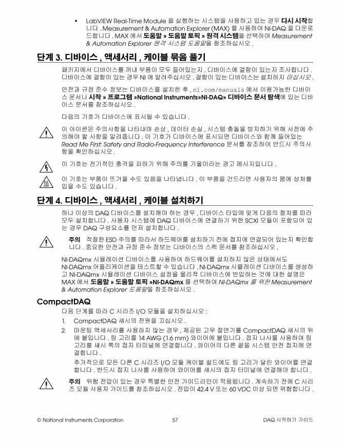
© National Instruments Corporation 57 DAQ 시작하기 가이드
• LabVIEW Real-Time Module을 실행하는 시스템을 사용하고 있는 경우 다시 시작합니다 . Measurement & Automation Explorer (MAX)를 사용하여 NI-DAQ을 다운로드합니다 . MAX에서 도움말 »도움말 토픽 »원격 시스템을 선택하여 Measurement & Automation Explorer 원격 시스템 도움말을 참조하십시오 .
단계 3. 디바이스 , 액세서리 , 케이블 묶음 풀기
패키지에서 디바이스를 꺼내 부품이 모두 들어있는지 , 디바이스에 결함이 있는지 조사합니다 . 디바이스에 결함이 있는 경우 NI에 알려주십시오 . 결함이 있는 디바이스는 설치하지 마십시오 .
안전과 규정 준수 정보는 디바이스를 설치한 후 , ni.com/manuals에서 이용가능한 디바이스 문서나 시작 »프로그램 »National Instruments»NI-DAQ»디바이스 문서 탐색에 있는 디바이스 문서를 참조하십시오 .
다음의 기호가 디바이스에 표시될 수 있습니다 .
이 아이콘은 주의사항을 나타내며 손상 , 데이터 손실 , 시스템 충돌을 방지하기 위해 사전에 주의해야 할 사항을 알려줍니다 . 이 기호가 디바이스에 표시되면 디바이스와 함께 들어있는 Read Me First: Safety and Radio-Frequency Interference 문서를 참조하여 반드시 주의사항을 확인하십시오 .
이 기호는 전기적인 충격을 피하기 위해 주의를 기울이라는 경고 메시지입니다 .
이 기호는 부품이 뜨거울 수도 있음을 나타냅니다 . 이 부품을 건드리면 사용자의 몸에 상처를 입을 수도 있습니다 .
단계 4. 디바이스 , 액세서리 , 케이블 설치하기
하나 이상의 DAQ 디바이스를 설치해야 하는 경우 , 디바이스 타입에 맞게 다음의 절차를 따라 모두 설치합니다 . 사용자 시스템에 DAQ 디바이스에 연결하기 위한 SCXI 모듈이 포함되어 있는 경우 DAQ 구성요소를 먼저 설치합니다 .
주의 적절한 ESD 주의를 따라서 하드웨어를 설치하기 전에 접지에 연결되어 있는지 확인합니다 . 중요한 안전과 규정 준수 정보는 디바이스의 스펙 문서를 참조하십시오 .
NI-DAQmx 시뮬레이션 디바이스를 사용하여 하드웨어를 설치하지 않은 상태에서도 NI-DAQmx 어플리케이션을 테스트할 수 있습니다 . NI-DAQmx 시뮬레이션 디바이스를 생성하고 NI-DAQmx 시뮬레이션 디바이스 설정을 물리적 디바이스에 반입하는 것에 대한 설명은 MAX에서 도움말 »도움말 토픽 »NI-DAQmx를 선택하여 NI-DAQmx를 위한 Measurement & Automation Explorer 도움말을 참조하십시오 .
CompactDAQ다음 단계를 따라 C 시리즈 I/O 모듈을 설치하십시오 :
1. CompactDAQ 섀시의 전원을 끄십시오 .
2. 마운팅 액세서리를 사용하지 않는 경우 , 제공된 고무 절연기를 CompactDAQ 섀시의 뒤에 붙입니다 . 링 고리를 14 AWG (1.6 mm) 와이어에 붙입니다 . 접지 나사를 사용하여 링 고리를 섀시 쪽의 접지 터미널에 연결합니다 . 와이어의 다른 끝을 시스템 안전 접지에 연결합니다 .
추가적으로 모든 다른 C 시리즈 I/O 모듈 케이블 쉴드에도 링 고리가 달린 와이어를 연결합니다 . 반드시 접지 나사를 사용하여 와이어를 섀시의 접지 터미널에 연결해야 합니다 .
주의 위험 전압이 있는 경우 특별한 안전 가이드라인이 적용됩니다 . 계속하기 전에 C 시리즈 모듈 사용자 가이드를 참조하십시오 . 전압이 42.4 V 또는 60 VDC 이상 되면 위험합니다 .
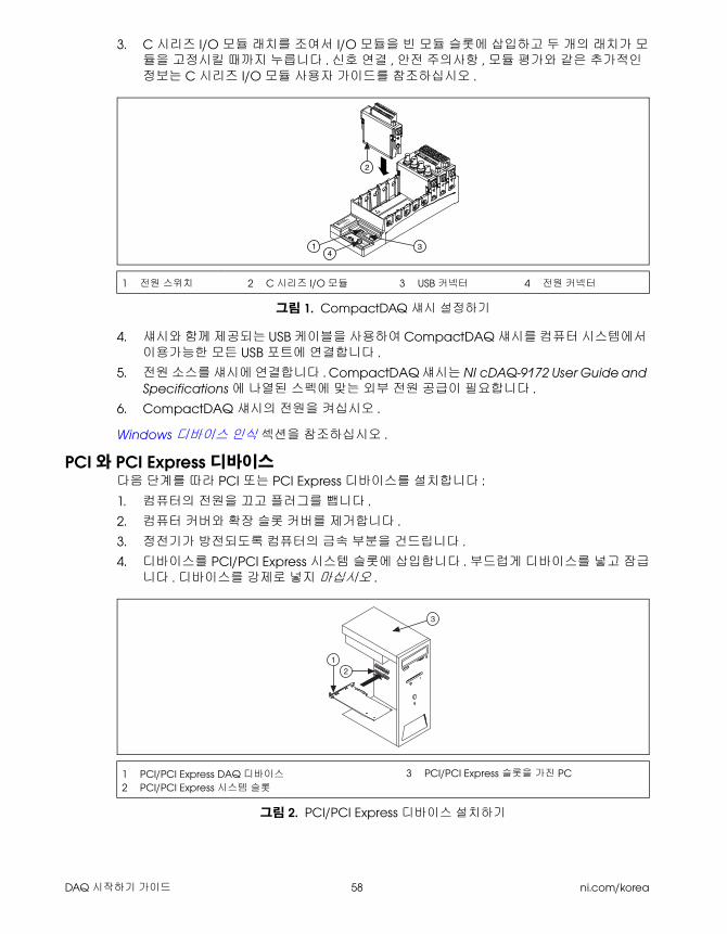
DAQ 시작하기 가이드 58 ni.com/korea
3. C 시리즈 I/O 모듈 래치를 조여서 I/O 모듈을 빈 모듈 슬롯에 삽입하고 두 개의 래치가 모듈을 고정시킬 때까지 누릅니다 . 신호 연결 , 안전 주의사항 , 모듈 평가와 같은 추가적인 정보는 C 시리즈 I/O 모듈 사용자 가이드를 참조하십시오 .
.
그림 1. CompactDAQ 섀시 설정하기
4. 섀시와 함께 제공되는 USB 케이블을 사용하여 CompactDAQ 섀시를 컴퓨터 시스템에서 이용가능한 모든 USB 포트에 연결합니다 .
5. 전원 소스를 섀시에 연결합니다 . CompactDAQ 섀시는 NI cDAQ-9172 User Guide and Specifications에 나열된 스펙에 맞는 외부 전원 공급이 필요합니다 .
6. CompactDAQ 섀시의 전원을 켜십시오 .
Windows 디바이스 인식 섹션을 참조하십시오 .
PCI 와 PCI Express 디바이스다음 단계를 따라 PCI 또는 PCI Express 디바이스를 설치합니다 :
1. 컴퓨터의 전원을 끄고 플러그를 뺍니다 .
2. 컴퓨터 커버와 확장 슬롯 커버를 제거합니다 .
3. 정전기가 방전되도록 컴퓨터의 금속 부분을 건드립니다 .
4. 디바이스를 PCI/PCI Express 시스템 슬롯에 삽입합니다 . 부드럽게 디바이스를 넣고 잠급니다 . 디바이스를 강제로 넣지 마십시오 .
그림 2. PCI/PCI Express 디바이스 설치하기
1 전원 스위치 2 C 시리즈 I/O 모듈 3 USB 커넥터 4 전원 커넥터
1 PCI/PCI Express DAQ 디바이스
2 PCI/PCI Express 시스템 슬롯
3 PCI/PCI Express 슬롯을 가진 PC
NI cDAQ-9051
Ready
Active
11-30 VDC
2 A Max
OFF
ON
431
2
3
12
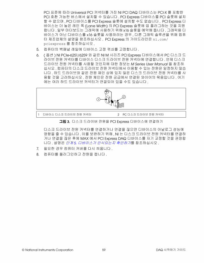
© National Instruments Corporation 59 DAQ 시작하기 가이드
PCI 표준에 따라 Universal PCI 커넥터를 가진 NI PCI DAQ 디바이스는 PCI-X를 포함한 PCI 호환 가능한 버스에서 설치할 수 있습니다 . PCI Express 디바이스를 PCI 슬롯에 설치할 수 없으며 , PCI 디바이스를 PCI Express 슬롯에 설치할 수도 없습니다 . PCI Express 디바이스는 더 높은 레인 폭 (Lane Width)의 PCI Express 슬롯에 업 플러그하는 것을 지원합니다 . 일부 마더보드는 그래픽에 사용하기 위해 x16 슬롯을 예약해 둡니다 . 그래픽용 디바이스가 아닌 디바이스를 x16 슬롯을 사용하려는 경우 , 다른 그래픽 솔루션을 위해 컴퓨터 제조업체의 설명을 참조하십시오 . PCI Express의 가이드라인은 ni.com/pciexpress를 참조하십시오 .
5. 컴퓨터의 백패널 레일에 디바이스 고정 꺾쇠를 고정합니다 .
6. (옵션 ) NI PCIe-6251/6259와 같은 NI M 시리즈 PCI Express 디바이스에서 PC 디스크 드라이브 전원 커넥터를 디바이스 디스크 드라이브 전원 커넥터에 연결합니다 . 언제 디스크 드라이브 전원 커넥터를 사용할 것인지에 대한 정보는 M Series User Manual을 참조하십시오 . 컴퓨터의 디스크 드라이브 전원 커넥터에서 이용할 수 있는 전원은 일정하지 않습니다 . 하드 드라이브와 같은 전원 체인 상에 있지 않은 디스크 드라이브 전원 커넥터를 사용할 것을 고려하십시오 . 전원 체인은 전원 공급에서 연결된 와이어의 묶음입니다 . 여기에는 여러 하드 드라이브 커넥터가 연결되어 있을 수도 있습니다 .
그림 3. 디스크 드라이버 전원을 PCI Express 디바이스에 연결하기
디스크 드라이브 전원 커넥터를 연결하거나 연결을 끊으면 디바이스의 아날로그 성능에 영향을 줄 수 있습니다 . 이를 보완하기 위해 , NI는 디스크 드라이브 전원 커넥터를 연결하거나 연결을 끊은 후에 MAX에서 PCI Express DAQ 디바이스를 자기 교정할 것을 권장합니다 . 설명은 단계 5. 디바이스가 인식되는지 확인하기를 참조하십시오 .
7. 필요한 경우 컴퓨터 커버를 다시 씌웁니다 .
8. 컴퓨터를 플러그인하고 전원을 켭니다 .
1 디바이스 디스크 드라이브 전원 커넥터 2 PC 디스크 드라이브 전원 커넥터
12
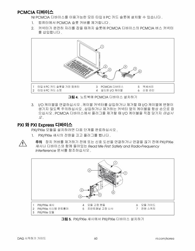
DAQ 시작하기 가이드 60 ni.com/korea
PCMCIA 디바이스NI PCMCIA 디바이스를 이용가능한 모든 타입 II PC 카드 슬롯에 설치할 수 있습니다 .
1. 컴퓨터에서 PCMCIA 슬롯 커버를 제거합니다 .
2. 커넥터가 완전히 자리를 잡을 때까지 슬롯에 PCMCIA 디바이스의 PCMCIA 버스 커넥터를 삽입합니다 .
그림 4. 노트북에 PCMCIA 디바이스 설치하기
3. I/O 케이블을 연결하십시오 . 케이블 커넥터를 삽입하거나 제거할 때 I/O 케이블에 변형이 생기지 않도록 주의하십시오 . 삽입하거나 제거하는 커넥터 옆의 케이블을 항상 손으로 잡으십시오 . PCMCIA 디바이스에서 플러그를 제거할 때 I/O 케이블을 직접 당기지 마십시오 .
PXI 와 PXI Express 디바이스PXI/PXIe 모듈을 설치하려면 다음 단계를 완료하십시오 .
1. PXI/PXIe 섀시의 전원을 끄고 플러그를 뺍니다 .
주의 장치 커버를 제거하기 전에 또는 신호 도선을 연결하거나 연결을 끊기 전에 PXI/PXIe 섀시나 디바이스와 함께 들어있는 Read Me First: Safety and Radio-Frequency Interference 문서를 참조하십시오 .
그림 5. PXI/PXIe 섀시에서 PXI/PXIe 디바이스 설치하기
1 타입 II PC 카드 슬롯을 가진 컴퓨터
2 타입 II PC 카드 소켓3 PCMCIA 디바이스
4 쉴드된 I/O 케이블5 액세서리
6 신호 라인
1 PXI/PXIe 섀시
2 PXI/PXIe 시스템 컨트롤러
3 PXI/PXIe 모듈
4 모듈 고정 핸들
5 프런트패널 고정 나사6 모듈 가이드
7 전원 스위치
®
®
DAQCard
1
2
34
56
3
2
4
PXI-1000B
7
56
1
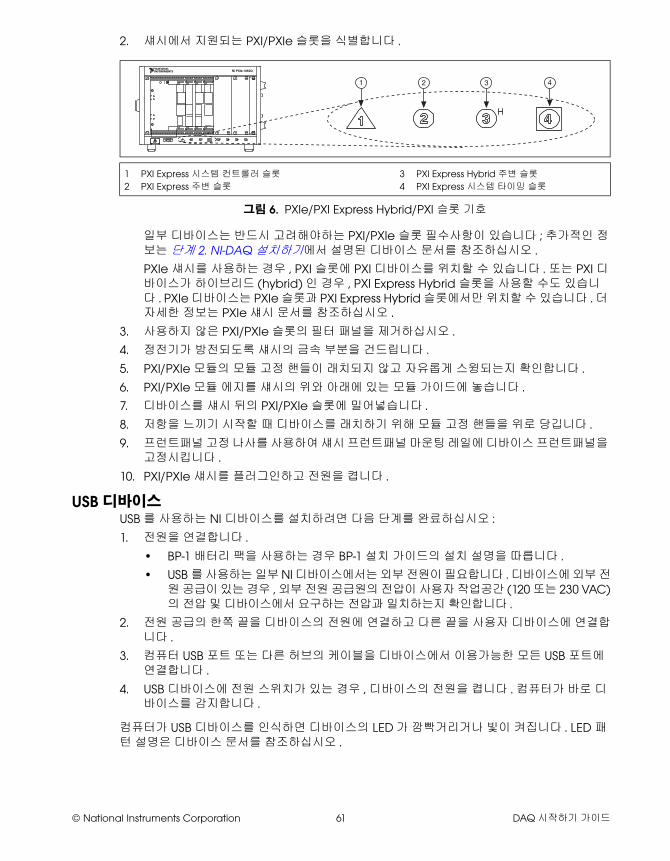
© National Instruments Corporation 61 DAQ 시작하기 가이드
2. 섀시에서 지원되는 PXI/PXIe 슬롯을 식별합니다 .
그림 6. PXIe/PXI Express Hybrid/PXI 슬롯 기호
일부 디바이스는 반드시 고려해야하는 PXI/PXIe 슬롯 필수사항이 있습니다 ; 추가적인 정보는 단계 2. NI-DAQ 설치하기에서 설명된 디바이스 문서를 참조하십시오 .
PXIe 섀시를 사용하는 경우 , PXI 슬롯에 PXI 디바이스를 위치할 수 있습니다 . 또는 PXI 디바이스가 하이브리드 (hybrid)인 경우 , PXI Express Hybrid 슬롯을 사용할 수도 있습니다 . PXIe 디바이스는 PXIe 슬롯과 PXI Express Hybrid 슬롯에서만 위치할 수 있습니다 . 더 자세한 정보는 PXIe 섀시 문서를 참조하십시오 .
3. 사용하지 않은 PXI/PXIe 슬롯의 필터 패널을 제거하십시오 .
4. 정전기가 방전되도록 섀시의 금속 부분을 건드립니다 .
5. PXI/PXIe 모듈의 모듈 고정 핸들이 래치되지 않고 자유롭게 스윙되는지 확인합니다 .
6. PXI/PXIe 모듈 에지를 섀시의 위와 아래에 있는 모듈 가이드에 놓습니다 .
7. 디바이스를 섀시 뒤의 PXI/PXIe 슬롯에 밀어넣습니다 .
8. 저항을 느끼기 시작할 때 디바이스를 래치하기 위해 모듈 고정 핸들을 위로 당깁니다 .
9. 프런트패널 고정 나사를 사용하여 섀시 프런트패널 마운팅 레일에 디바이스 프런트패널을 고정시킵니다 .
10. PXI/PXIe 섀시를 플러그인하고 전원을 켭니다 .
USB 디바이스USB를 사용하는 NI 디바이스를 설치하려면 다음 단계를 완료하십시오 :
1. 전원을 연결합니다 .
• BP-1 배터리 팩을 사용하는 경우 BP-1 설치 가이드의 설치 설명을 따릅니다 .
• USB를 사용하는 일부 NI 디바이스에서는 외부 전원이 필요합니다 . 디바이스에 외부 전원 공급이 있는 경우 , 외부 전원 공급원의 전압이 사용자 작업공간 (120 또는 230 VAC)의 전압 및 디바이스에서 요구하는 전압과 일치하는지 확인합니다 .
2. 전원 공급의 한쪽 끝을 디바이스의 전원에 연결하고 다른 끝을 사용자 디바이스에 연결합니다 .
3. 컴퓨터 USB 포트 또는 다른 허브의 케이블을 디바이스에서 이용가능한 모든 USB 포트에 연결합니다 .
4. USB 디바이스에 전원 스위치가 있는 경우 , 디바이스의 전원을 켭니다 . 컴퓨터가 바로 디바이스를 감지합니다 .
컴퓨터가 USB 디바이스를 인식하면 디바이스의 LED가 깜빡거리거나 빛이 켜집니다 . LED 패턴 설명은 디바이스 문서를 참조하십시오 .
1 PXI Express 시스템 컨트롤러 슬롯
2 PXI Express 주변 슬롯3 PXI Express Hybrid 주변 슬롯
4 PXI Express 시스템 타이밍 슬롯
NI PXIe-1062Q
1 2 3 4
DAQ 시작하기 가이드 62 ni.com/korea
Windows 디바이스 인식Windows는 하드웨어가 설치되고 컴퓨터가 재부팅한 후 새롭게 설치된 디바이스를 인식합니다 . 일부 Windows 시스템에서는 NI 디바이스를 설치할 때마다 새 하드웨어 발견 마법사가 대화 상자와 함께 열립니다 . 소프트웨어 자동으로 설치 ( 권장 )가 기본으로 선택되어 있습니다 . 다음 또는 예를 클릭하여 각 디바이스의 소프트웨어를 설치합니다 .
Windows가 CompactDAQ 디바이스처럼 새롭게 설치된 NI USB 디바이스를 인식한 후에는 대화 상자가 나타나 다음과 같은 옵션을 선택하도록 합니다 (옵션은 시스템에 설치된 디바이스와 소프트웨어에 따라 다양합니다 ):
• Begin a Measurement with LabVIEW는 LabVIEW를 시작합니다 .
• Begin a Measurement with This Device Using NI LabVIEW SignalExpress는 LabVIEW SignalExpress에서 사용자 디바이스의 채널을 사용하는 DAQ 단계를 엽니다 . CompactDAQ 섀시가 설치되어 있는 경우 , 대화 상자가 나타나 사용하려는 모듈을 선택하도록 합니다 . 연결하고 설정하려는 액세사리 , SCXI 또는 센서가 있는 경우 , 다음 액세서리 섹션과 단계 5. 디바이스가 인식되는지 확인하기에서 단계 9. 테스트 패널 실행하기까지를 참조하십시오 . 그렇지않으면 MAX에서 셋팅을 설정할 필요가 없습니다 . LabVIEW SignalExpress에서 DAQ 측정하기에 대한 자세한 정보는 단계 11. 사용자 어플리케이션 소프트웨어에서 NI-DAQmx 사용을 참조하십시오 .
• Configure and Test This Device는 MAX를 열어 디바이스에 대한 셋팅을 설정할 수 있도록 합니다 .
• Run Test Panels는 사용자 디바이스에 대한 MAX 테스트 패널을 엽니다 .
• Take No Action은 시스템에서 디바이스의 설정을 변경하지 않고 어플리케이션도 열지 않습니다 .
액세서리설치 가이드에 있는 설명을 따라 액세서리와 터미널 블록을 설치하십시오 . SCXI와 SCC 신호 컨디셔닝 시스템에 대해서는 , 이 가이드의 단계 7. 신호 컨디셔닝이나 스위치 디바이스 설치하기까지의 설명을 따릅니다 .
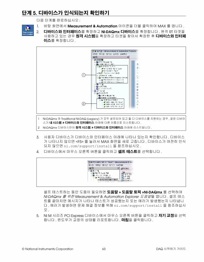
© National Instruments Corporation 63 DAQ 시작하기 가이드
단계 5. 디바이스가 인식되는지 확인하기
다음 단계를 완료하십시오 :
1. 바탕 화면에서 Measurement & Automation 아이콘을 더블 클릭하여 MAX를 엽니다 .
2. 디바이스와 인터페이스를 확장하고 NI-DAQmx 디바이스를 확장합니다 . 원격 RT 타겟을 사용하고 있는 경우 원격 시스템을 확장하고 타겟을 찾아서 확장한 후 디바이스와 인터페이스를 확장합니다 .
3. 사용자 디바이스가 디바이스와 인터페이스 아래에 나타나 있는지 확인합니다 . 디바이스가 나타나지 않으면 <F5>를 눌러서 MAX 화면을 새로 고칩니다 . 디바이스가 여전히 인식되지 않으면 ni.com/support/install을 참조하십시오 .
4. 디바이스에서 마우스 오른쪽 버튼을 클릭하고 셀프 테스트를 선택합니다 .
셀프 테스트하는 동안 도움이 필요하면 도움말 »도움말 토픽 »NI-DAQmx를 선택하여 NI-DAQmx를 위한 Measurement & Automation Explorer 도움말을 엽니다 . 셀프 테스트를 끝마치면 메시지가 나타나 테스트가 성공했는지 또는 에러가 발생했는지 나타냅니다 . 에러가 발생하면 문제 해결 정보를 위해 ni.com/support/install을 참조하십시오 .
5. NI M 시리즈 PCI Express 디바이스에서 마우스 오른쪽 버튼을 클릭하고 자기 교정을 선택합니다 . 윈도우가 교정의 상태를 리포트합니다 . 마침을 클릭합니다 .
1 NI-DAQmx와 Traditional NI-DAQ (Legacy)가 모두 설치되어 있고 둘 다 디바이스를 지원하는 경우 , 같은 디바이
스가 내 시스템 »디바이스와 인터페이스 아래에 다른 이름으로 리스트됩니다 .
2 NI-DAQmx 디바이스만이 원격 시스템 »디바이스와 인터페이스 아래에 리스트됩니다 .
1
2
DAQ 시작하기 가이드 64 ni.com/korea
단계 6. 디바이스 셋팅 설정하기
설치하려는 각 디바이스를 설정합니다 :
1. 디바이스 이름에서 마우스 오른쪽 버튼을 클릭하고 프로퍼티를 선택합니다 .
2. 디바이스를 컨트롤하려는 시스템 (내 시스템 또는 원격 시스템 )과 NI-DAQ API의 폴더 아래의 디바이스 이름을 클릭합니다 .
3. 디바이스 프로퍼티를 설정합니다 .
• 액세서리를 사용하고 있다면 액세서리 정보를 추가합니다 .
• IEEE 1451.4 transducer electronic data sheet (TEDS) 센서와 주변 액세서리의 경우 앞에서 설명한 것처럼 디바이스를 설정하고 액세서리를 추가합니다 . TEDS 스캔을 클릭합니다 . MAX에서 디바이스에 직접 케이블로 연결된 TEDS 센서를 설정하려면 , 디바이스와 인터페이스 아래의 모듈에서 마우스 오른쪽 버튼을 클릭하고 TEDS 설정을 선택합니다 .
4. 변경을 받아들이려면 확인을 클릭합니다 .
단계 7. 신호 컨디셔닝이나 스위치 디바이스 설치하기
사용자 시스템이 SCXI 신호 컨디셔닝 모듈 , SC 캐리어와 SCC 모듈과 같은 신호 컨디셔닝 구성요소 (Signal Conditioning Components, SCC), 터미널 블록 , 또는 스위치 모듈을 포함하고 있는 경우 , 해당 제품의 시작하기 가이드를 참조하여 신호 컨디셔닝이나 스위치 하드웨어를 설치하고 설정합니다 .
단계 8. 센서와 신호 라인 연결하기
설치된 각 디바이스에 대해 센서와 신호 라인을 터미널 블록이나 액세서리 터미널에 연결합니다 .
핀 할당 (핀아웃 )은 MAX 도움말 메뉴에서 접근할 수 있는 NI-DAQmx를 위한 Measurement & Automation Explorer 도움말의 NI-DAQmx Device Terminals Help 및 설치한 후 시작 »프로그램 »National Instruments»NI-DAQ»디바이스 문서 탐색에서 접근할 수 있는 디바이스 문서 탐색기의 디바이스 문서에서 찾아볼 수 있습니다 . DAQ 어시스턴트를 사용하여 사용자 시스템의 NI-DAQmx 태스크와 버추얼 채널의 연결 다이어그램을 보고 인쇄할 수 있습니다 . DAQ 어시스턴트를 열려면 MAX에서 DAQ 어시스턴트를 사용하여 태스크 설정하기를 참조하십시오 . 태스크 또는 버추얼 채널을 선택하고 연결 다이어그램 탭을 클릭합니다 . 태스크에서 각 버추얼 채널을 선택하여 센서에서 연결 블록까지의 연결에 대한 터미널 이름과 번호를 봅니다 .
센서에 대한 정보는 ni.com/sensors 또는 시작 »프로그램 »National Instruments»NI-DAQ»NI-DAQmx 도움말에서 접근할 수 있는 NI-DAQmx 도움말의 센서 항목을 참조하십시오 . IEEE 1451.4 TEDS 스마트 센서에 대한 정보는 ni.com/teds를 참조하십시오 .
LabVIEW SignalExpress를 사용하는 경우 , 단계 11. 사용자 어플리케이션 소프트웨어에서 NI-DAQmx 사용을 참조하십시오 .
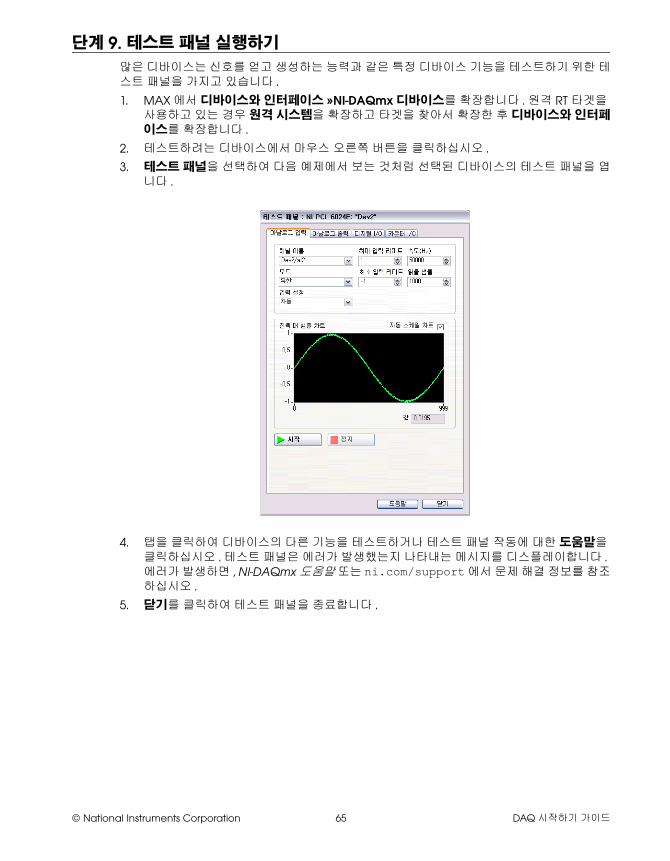
© National Instruments Corporation 65 DAQ 시작하기 가이드
단계 9. 테스트 패널 실행하기
많은 디바이스는 신호를 얻고 생성하는 능력과 같은 특정 디바이스 기능을 테스트하기 위한 테스트 패널을 가지고 있습니다 .
1. MAX에서 디바이스와 인터페이스 »NI-DAQmx 디바이스를 확장합니다 . 원격 RT 타겟을 사용하고 있는 경우 원격 시스템을 확장하고 타겟을 찾아서 확장한 후 디바이스와 인터페이스를 확장합니다 .
2. 테스트하려는 디바이스에서 마우스 오른쪽 버튼을 클릭하십시오 .
3. 테스트 패널을 선택하여 다음 예제에서 보는 것처럼 선택된 디바이스의 테스트 패널을 엽니다 .
4. 탭을 클릭하여 디바이스의 다른 기능을 테스트하거나 테스트 패널 작동에 대한 도움말을 클릭하십시오 . 테스트 패널은 에러가 발생했는지 나타내는 메시지를 디스플레이합니다 . 에러가 발생하면 , NI-DAQmx 도움말 또는 ni.com/support에서 문제 해결 정보를 참조하십시오 .
5. 닫기를 클릭하여 테스트 패널을 종료합니다 .
DAQ 시작하기 가이드 66 ni.com/korea
단계 10. NI-DAQmx 측정하기
NI-DAQmx 채널과 태스크 물리적 채널은 아날로그나 디지털 신호를 측정하거나 생성할 수 있는 터미널 또는 핀입니다 . 버추얼 채널은 물리적 채널에 대한 이름과 입력 터미널 연결 , 측정이나 생성 타입 , 스케일링 정보와 같은 셋팅을 설정합니다 . NI-DAQmx에서 버추얼 채널은 모든 측정에 필수적입니다 .
태스크는 타이밍 , 트리거 , 기타 프로퍼티를 가진 하나 또는 그 이상의 버추얼 채널입니다 . 개념적으로 태스크는 수행하려는 측정 또는 생성을 나타냅니다 . 태스크에서 설정 정보를 설정 및 저장하고 태스크를 어플리케이션에서 사용할 수 있습니다 . 채널과 태스크에 대한 자세한 정보는 NI-DAQmx 도움말을 참조하십시오 .
NI-DAQmx를 사용하는 경우 , DAQ 어시스턴트를 사용하여 MAX나 사용자 어플리케이션 소프트웨어의 버추얼 채널과 태스크를 설정하십시오 .
MAX 에서 DAQ 어시스턴트를 사용하여 태스크 설정하기다음 단계를 따라 MAX에서 DAQ 어시스턴트를 사용하여 태스크를 생성합니다 :
1. MAX의 채널 및 태스크 관리에서 마우스 오른쪽 버튼을 클릭하고 새로 생성을 선택하여 DAQ 어시스턴트를 엽니다 .
2. 새로 생성 윈도우에서 NI-DAQmx 태스크를 선택하고 다음을 클릭합니다 .
3. 신호 수집 또는 신호 생성을 선택합니다 .
4. 아날로그 입력 등의 I/O 타입을 선택한 후 전압과 같은 측정 타입을 선택합니다 .
5. 사용할 물리적 채널을 선택하고 다음을 클릭합니다 .
6. 태스크의 이름을 정하고 마침을 클릭합니다 .
7. 개별 채널 셋팅을 설정합니다 . 사용자가 태스크에 지정한 각 물리적 채널이 버추얼 채널 이름을 받습니다 . 입력 범위 또는 다른 셋팅을 수정하려면 채널을 선택합니다 . 물리적 채널 정보를 보려면 상세설명 보이기를 클릭합니다 . 태스크의 타이밍과 트리거링을 설정합니다 . 테스트를 클릭합니다 .
단계 11. 사용자 어플리케이션 소프트웨어에서 NI-DAQmx 사용
DAQ 어시스턴트를 LabVIEW, LabWindows/CVI, 또는 Measurement Studio 버전 7.x 또는 이후 또는 LabVIEW SignalExpress 버전 2.x 또는 이후 버전과 함께 사용할 수 있습니다 .
NI-DAQmx CD에는 LabVIEW SignalExpress LE가 포함되어 있습니다 . LabVIEW SignalExpress LE는 데이터 로깅 어플리케이션을 위해 특별히 설계된 사용하기 쉬운 설정 기반 도구입니다 . 어플리케이션은 시작 »프로그램 »National Instruments»LabVIEW SignalExpress에서 사용 가능합니다 . LabVIEW SignalExpress Help는 LabVIEW SignalExpress의 Help»Help Topics»LabVIEW SignalExpress 내에 있습니다 .
사용자 어플리케이션 소프트웨어에서 시작하려면 다음 길라잡이를 참조하십시오 :
• LabVIEW DAQ 어시스턴트 길라잡이는 LabVIEW내의 도움말 »시작하기 »DAQ 시작하기 »LabVIEW 에서 NI-DAQmx 측정 사용하기에 있습니다 .
• LabWindows/CVI DAQ Assistant 길라잡이는 LabWindows/CVI내의 Help»Help Topics»Taking an NI-DAQmx Measurement in LabWindows/CVI에 있습니다 .
© National Instruments Corporation 67 DAQ 시작하기 가이드
• Measurement Studio DAQ Assistant 길라잡이는 Measurement Studio»NI Measurement Studio Help»Getting Started with the Measurement Studio Class Libraries»Measurement Studio Walkthroughs»Walkthrough: Creating a Measurement Studio NI-DAQmx Application에 있습니다 .
• LabVIEW SignalExpress DAQ Assistant 길라잡이는 LabVIEW SignalExpress내의 Help»Getting Started with»Taking an NI-DAQmx Measurement in LabVIEW SignalExpress에 있습니다 .
예제예제를 사용하여 새로운 어플리케이션을 개발하거나 기존의 어플리케이션에 예제 코드를 추가할 수 있습니다 .
추가적인 예제는 ni.com/zone을 참조하십시오 . 하드웨어를 설치하지 않고 예제를 실행하는 경우 , NI-DAQmx 시뮬레이션 디바이스를 사용할 수 있습니다 . MAX에서 NI-DAQmx 시뮬레이트 디바이스 생성에 대한 설명은 도움말 »도움말 토픽 »NI-DAQmx를 선택하여 NI-DAQmx를 위한 Measurement & Automation Explorer Help 도움말을 참조하십시오 .
추가적인 정보
디바이스 문서를 설치한 후 , 시작 »프로그램 »National Instruments»NI-DAQ»디바이스 문서 탐색에서 탐색기와 디바이스 문서를 열 수 있습니다 . NI-DAQmx 도움말과 DAQ 시작하기 가이드와 같은 NI-DAQ 소프트웨어 문서는 시작 »프로그램 »National Instruments»NI-DAQ»NI-DAQmx 문서 제목에서 볼 수 있습니다 .
MAX에 있는 디바이스에서 마우스 오른쪽 버튼을 클릭하거나 도움말 »온라인 디바이스 문서를 선택하여 온라인 디바이스 문서를 볼 수 있습니다 . 탐색기 윈도우에서 ni.com/manuals이 열리고 관련된 디바이스 문서 탐색 결과가 나타납니다 . ni.com/manuals 웹사이트에는 NI-DAQmx 릴리즈 및 아직 NI-DAQ 디바이스 문서 탐색기로 검색할 수 없는 새로운 버전의 디바이스 문서에 이르기까지 모든 새로운 디바이스에 대한 문서가 들어있습니다 .
소프트웨어 어플리케이션 예제 위치
LabVIEW 또는 LabWindows/CVI 도움말 »예제 찾기
LabVIEW SignalExpress Program Files\National Instruments\SignalExpress\Examples
ANSI C NI-DAQ\Examples\DAQmx ANSI C
Measurement Studio-지원 언어 MFC 7.0 C++ NI-DAQ\Examples\MStudioVC2003
Visual Basic .NET과 Visual Studio 2003*를 위한 C# 예제
NI-DAQ\Examples\DotNET1.1
MFC 8.0 C++ NI-DAQ\Examples\MStudioVC2005
Visual Basic .NET과 Visual Studio 2005*를 위한 C# 예제
NI-DAQ\Examples\DotNET2.0
* Measurement Studio는 필수가 아님
National Instruments, NI, ni.com과 LabVIEW는 National Instruments Corporation의 상표들입니다 . National Instruments의 상표들에 관한 더 많은 정보를 원하신다면 ni.com/legal 에서 Terms of Use 란을 참조하십시오 .이 문서에서 언급된 다른 제품과 회사의 이름들은 각각 해당 회사들의 상표이거나 상호들입니다 .적절한 위치에서 내쇼날인스트루먼트의 특허권을 참조할 수 있습니다 : 소프트웨어의 Help»Patents, CD의 patents.txt 파일 , 또는 ni.com/patents.
© 2003–2007 National Instruments Corporation. 판권 소유 . 373235M-01 0607
문제 해결
DAQ 하드웨어나 소프트웨어를 설치하는데 문제가 있는 경우 다음 리소스를 사용하십시오 :
• 문제 해결을 위한 설명은 ni.com/support/install의 Hardware Installation/Configuration Troubleshooter를 참조하십시오 .
• 공통된 설치와 프로그램 문제 및 자주 묻는 질문 (FAQ)에 대한 답은 ni.com/kb를 참조하십시오 .
• 디바이스가 손상되어 복구나 디바이스 교정을 위해 NI 제품을 반환해야 하는 경우 , ni.com/info에서 정보 코드 rdsenn을 입력하여 RMA (Return Merchandise Authorization) 방법을 배우십시오 .
전세계에 걸친 기술 지원
추가적인 지원은 ni.com/support 또는 ni.com/zone을 참조하십시오 . 신호 컨디셔닝 제품에 대한 더 많은 지원 정보는 디바이스와 함께 들어있는 Signal Conditioning Technical Support Information 문서를 참조하십시오 .
National Instruments 본사의 주소는 11500 North Mopac Expressway, Austin, Texas, 78759-3504입니다 . 또한 National Instruments는 고객 지원을 위해 전세계 여러 곳에 지점을 두고 있습니다 .

![Malzahn 2010 Spring Install Day1[1]](https://img.pdfslide.org/doc/110x75/577cd2631a28ab9e78955b5f/malzahn-2010-spring-install-day11.jpg)